US6776094B1 - Kit For Microcontact Printing - Google Patents

Kit For Microcontact Printing Download PDF

Info

Publication number
US6776094B1
US6776094B1 US09/164,733 US16473398A US6776094B1 US 6776094 B1 US6776094 B1 US 6776094B1 US 16473398 A US16473398 A US 16473398A US 6776094 B1 US6776094 B1 US 6776094B1
Authority
US
United States
Prior art keywords
article
self
kit
assembled monolayer
species
Prior art date
Legal status (The legal status is an assumption and is not a legal conclusion. Google has not performed a legal analysis and makes no representation as to the accuracy of the status listed.)
Expired - Fee Related
Application number
US09/164,733
Inventor
George M. Whitesides
Amit Kumar
Current Assignee (The listed assignees may be inaccurate. Google has not performed a legal analysis and makes no representation or warranty as to the accuracy of the list.)
Harvard College
Original Assignee
Harvard College
Priority date (The priority date is an assumption and is not a legal conclusion. Google has not performed a legal analysis and makes no representation as to the accuracy of the date listed.)
Filing date
Publication date
Priority claimed from US08/131,841 external-priority patent/US5512131A/en
Priority claimed from US08/676,951 external-priority patent/US6180239B1/en
Priority claimed from US08/677,309 external-priority patent/US5900160A/en
Priority to US09/164,733 priority Critical patent/US6776094B1/en
Application filed by Harvard College filed Critical Harvard College
Priority to US10/776,427 priority patent/US20040159633A1/en
Publication of US6776094B1 publication Critical patent/US6776094B1/en
Application granted granted Critical
Priority to US12/187,070 priority patent/US7875197B2/en
Assigned to PRESIDENT AND FELLOWS OF HARVARD COLLEGE reassignment PRESIDENT AND FELLOWS OF HARVARD COLLEGE ASSIGNMENT OF ASSIGNORS INTEREST (SEE DOCUMENT FOR DETAILS). Assignors: BIEBUYCK, HANS, JACKMAN, REBECCA J, KIM, ENOCH, XIA, YOUNAN, KUMAR, AMIT, PRENTISS, MARA G, BERGGREN, KARL K, WHITESIDES, GEORGE M, GORMAN, CHRISTOPHER B, WILBUR, JAMES L, MRKSICH, MILAN
Assigned to NATIONAL INSTITUTES OF HEALTH (NIH), U.S. DEPT. OF HEALTH AND HUMAN SERVICES (DHHS), U.S. GOVERNMENT reassignment NATIONAL INSTITUTES OF HEALTH (NIH), U.S. DEPT. OF HEALTH AND HUMAN SERVICES (DHHS), U.S. GOVERNMENT CONFIRMATORY LICENSE (SEE DOCUMENT FOR DETAILS). Assignors: HARVARD UNIVERSITY
Anticipated expiration legal-status Critical
Expired - Fee Related legal-status Critical Current

Links

Images

Classifications

    • BPERFORMING OPERATIONS; TRANSPORTING
    • B01PHYSICAL OR CHEMICAL PROCESSES OR APPARATUS IN GENERAL
    • B01LCHEMICAL OR PHYSICAL LABORATORY APPARATUS FOR GENERAL USE
    • B01L3/00Containers or dishes for laboratory use, e.g. laboratory glassware; Droppers
    • B01L3/50Containers for the purpose of retaining a material to be analysed, e.g. test tubes
    • B01L3/508Containers for the purpose of retaining a material to be analysed, e.g. test tubes rigid containers not provided for above
    • B01L3/5085Containers for the purpose of retaining a material to be analysed, e.g. test tubes rigid containers not provided for above for multiple samples, e.g. microtitration plates
    • BPERFORMING OPERATIONS; TRANSPORTING
    • B01PHYSICAL OR CHEMICAL PROCESSES OR APPARATUS IN GENERAL
    • B01LCHEMICAL OR PHYSICAL LABORATORY APPARATUS FOR GENERAL USE
    • B01L3/00Containers or dishes for laboratory use, e.g. laboratory glassware; Droppers
    • B01L3/50Containers for the purpose of retaining a material to be analysed, e.g. test tubes
    • B01L3/508Containers for the purpose of retaining a material to be analysed, e.g. test tubes rigid containers not provided for above
    • B01L3/5088Containers for the purpose of retaining a material to be analysed, e.g. test tubes rigid containers not provided for above confining liquids at a location by surface tension, e.g. virtual wells on plates, wires
    • BPERFORMING OPERATIONS; TRANSPORTING
    • B05SPRAYING OR ATOMISING IN GENERAL; APPLYING FLUENT MATERIALS TO SURFACES, IN GENERAL
    • B05DPROCESSES FOR APPLYING FLUENT MATERIALS TO SURFACES, IN GENERAL
    • B05D1/00Processes for applying liquids or other fluent materials
    • B05D1/28Processes for applying liquids or other fluent materials performed by transfer from the surfaces of elements carrying the liquid or other fluent material, e.g. brushes, pads, rollers
    • B05D1/283Transferring monomolecular layers or solutions of molecules adapted for forming monomolecular layers from carrying elements
    • BPERFORMING OPERATIONS; TRANSPORTING
    • B82NANOTECHNOLOGY
    • B82YSPECIFIC USES OR APPLICATIONS OF NANOSTRUCTURES; MEASUREMENT OR ANALYSIS OF NANOSTRUCTURES; MANUFACTURE OR TREATMENT OF NANOSTRUCTURES
    • B82Y10/00Nanotechnology for information processing, storage or transmission, e.g. quantum computing or single electron logic
    • BPERFORMING OPERATIONS; TRANSPORTING
    • B82NANOTECHNOLOGY
    • B82YSPECIFIC USES OR APPLICATIONS OF NANOSTRUCTURES; MEASUREMENT OR ANALYSIS OF NANOSTRUCTURES; MANUFACTURE OR TREATMENT OF NANOSTRUCTURES
    • B82Y30/00Nanotechnology for materials or surface science, e.g. nanocomposites
    • BPERFORMING OPERATIONS; TRANSPORTING
    • B82NANOTECHNOLOGY
    • B82YSPECIFIC USES OR APPLICATIONS OF NANOSTRUCTURES; MEASUREMENT OR ANALYSIS OF NANOSTRUCTURES; MANUFACTURE OR TREATMENT OF NANOSTRUCTURES
    • B82Y40/00Manufacture or treatment of nanostructures
    • GPHYSICS
    • G02OPTICS
    • G02BOPTICAL ELEMENTS, SYSTEMS OR APPARATUS
    • G02B5/00Optical elements other than lenses
    • G02B5/18Diffraction gratings
    • G02B5/1847Manufacturing methods
    • G02B5/1857Manufacturing methods using exposure or etching means, e.g. holography, photolithography, exposure to electron or ion beams
    • GPHYSICS
    • G02OPTICS
    • G02BOPTICAL ELEMENTS, SYSTEMS OR APPARATUS
    • G02B6/00Light guides; Structural details of arrangements comprising light guides and other optical elements, e.g. couplings
    • G02B6/10Light guides; Structural details of arrangements comprising light guides and other optical elements, e.g. couplings of the optical waveguide type
    • G02B6/12Light guides; Structural details of arrangements comprising light guides and other optical elements, e.g. couplings of the optical waveguide type of the integrated circuit kind
    • G02B6/122Basic optical elements, e.g. light-guiding paths
    • G02B6/124Geodesic lenses or integrated gratings
    • GPHYSICS
    • G02OPTICS
    • G02BOPTICAL ELEMENTS, SYSTEMS OR APPARATUS
    • G02B6/00Light guides; Structural details of arrangements comprising light guides and other optical elements, e.g. couplings
    • G02B6/10Light guides; Structural details of arrangements comprising light guides and other optical elements, e.g. couplings of the optical waveguide type
    • G02B6/12Light guides; Structural details of arrangements comprising light guides and other optical elements, e.g. couplings of the optical waveguide type of the integrated circuit kind
    • G02B6/13Integrated optical circuits characterised by the manufacturing method
    • G02B6/136Integrated optical circuits characterised by the manufacturing method by etching
    • GPHYSICS
    • G03PHOTOGRAPHY; CINEMATOGRAPHY; ANALOGOUS TECHNIQUES USING WAVES OTHER THAN OPTICAL WAVES; ELECTROGRAPHY; HOLOGRAPHY
    • G03FPHOTOMECHANICAL PRODUCTION OF TEXTURED OR PATTERNED SURFACES, e.g. FOR PRINTING, FOR PROCESSING OF SEMICONDUCTOR DEVICES; MATERIALS THEREFOR; ORIGINALS THEREFOR; APPARATUS SPECIALLY ADAPTED THEREFOR
    • G03F7/00Photomechanical, e.g. photolithographic, production of textured or patterned surfaces, e.g. printing surfaces; Materials therefor, e.g. comprising photoresists; Apparatus specially adapted therefor
    • G03F7/0002Lithographic processes using patterning methods other than those involving the exposure to radiation, e.g. by stamping
    • GPHYSICS
    • G03PHOTOGRAPHY; CINEMATOGRAPHY; ANALOGOUS TECHNIQUES USING WAVES OTHER THAN OPTICAL WAVES; ELECTROGRAPHY; HOLOGRAPHY
    • G03FPHOTOMECHANICAL PRODUCTION OF TEXTURED OR PATTERNED SURFACES, e.g. FOR PRINTING, FOR PROCESSING OF SEMICONDUCTOR DEVICES; MATERIALS THEREFOR; ORIGINALS THEREFOR; APPARATUS SPECIALLY ADAPTED THEREFOR
    • G03F7/00Photomechanical, e.g. photolithographic, production of textured or patterned surfaces, e.g. printing surfaces; Materials therefor, e.g. comprising photoresists; Apparatus specially adapted therefor
    • G03F7/16Coating processes; Apparatus therefor
    • G03F7/165Monolayers, e.g. Langmuir-Blodgett
    • HELECTRICITY
    • H01ELECTRIC ELEMENTS
    • H01LSEMICONDUCTOR DEVICES NOT COVERED BY CLASS H10
    • H01L21/00Processes or apparatus adapted for the manufacture or treatment of semiconductor or solid state devices or of parts thereof
    • H01L21/02Manufacture or treatment of semiconductor devices or of parts thereof
    • H01L21/04Manufacture or treatment of semiconductor devices or of parts thereof the devices having at least one potential-jump barrier or surface barrier, e.g. PN junction, depletion layer or carrier concentration layer
    • H01L21/48Manufacture or treatment of parts, e.g. containers, prior to assembly of the devices, using processes not provided for in a single one of the subgroups H01L21/06 - H01L21/326
    • H01L21/4814Conductive parts
    • H01L21/4846Leads on or in insulating or insulated substrates, e.g. metallisation
    • H01L21/4867Applying pastes or inks, e.g. screen printing
    • HELECTRICITY
    • H01ELECTRIC ELEMENTS
    • H01LSEMICONDUCTOR DEVICES NOT COVERED BY CLASS H10
    • H01L21/00Processes or apparatus adapted for the manufacture or treatment of semiconductor or solid state devices or of parts thereof
    • H01L21/70Manufacture or treatment of devices consisting of a plurality of solid state components formed in or on a common substrate or of parts thereof; Manufacture of integrated circuit devices or of parts thereof
    • H01L21/71Manufacture of specific parts of devices defined in group H01L21/70
    • H01L21/768Applying interconnections to be used for carrying current between separate components within a device comprising conductors and dielectrics
    • BPERFORMING OPERATIONS; TRANSPORTING
    • B01PHYSICAL OR CHEMICAL PROCESSES OR APPARATUS IN GENERAL
    • B01JCHEMICAL OR PHYSICAL PROCESSES, e.g. CATALYSIS OR COLLOID CHEMISTRY; THEIR RELEVANT APPARATUS
    • B01J2219/00Chemical, physical or physico-chemical processes in general; Their relevant apparatus
    • B01J2219/00274Sequential or parallel reactions; Apparatus and devices for combinatorial chemistry or for making arrays; Chemical library technology
    • B01J2219/00277Apparatus
    • B01J2219/00351Means for dispensing and evacuation of reagents
    • B01J2219/00382Stamping
    • BPERFORMING OPERATIONS; TRANSPORTING
    • B01PHYSICAL OR CHEMICAL PROCESSES OR APPARATUS IN GENERAL
    • B01JCHEMICAL OR PHYSICAL PROCESSES, e.g. CATALYSIS OR COLLOID CHEMISTRY; THEIR RELEVANT APPARATUS
    • B01J2219/00Chemical, physical or physico-chemical processes in general; Their relevant apparatus
    • B01J2219/00274Sequential or parallel reactions; Apparatus and devices for combinatorial chemistry or for making arrays; Chemical library technology
    • B01J2219/00583Features relative to the processes being carried out
    • B01J2219/00603Making arrays on substantially continuous surfaces
    • B01J2219/00605Making arrays on substantially continuous surfaces the compounds being directly bound or immobilised to solid supports
    • B01J2219/0061The surface being organic
    • BPERFORMING OPERATIONS; TRANSPORTING
    • B01PHYSICAL OR CHEMICAL PROCESSES OR APPARATUS IN GENERAL
    • B01JCHEMICAL OR PHYSICAL PROCESSES, e.g. CATALYSIS OR COLLOID CHEMISTRY; THEIR RELEVANT APPARATUS
    • B01J2219/00Chemical, physical or physico-chemical processes in general; Their relevant apparatus
    • B01J2219/00274Sequential or parallel reactions; Apparatus and devices for combinatorial chemistry or for making arrays; Chemical library technology
    • B01J2219/00583Features relative to the processes being carried out
    • B01J2219/00603Making arrays on substantially continuous surfaces
    • B01J2219/00605Making arrays on substantially continuous surfaces the compounds being directly bound or immobilised to solid supports
    • B01J2219/00612Making arrays on substantially continuous surfaces the compounds being directly bound or immobilised to solid supports the surface being inorganic
    • BPERFORMING OPERATIONS; TRANSPORTING
    • B01PHYSICAL OR CHEMICAL PROCESSES OR APPARATUS IN GENERAL
    • B01JCHEMICAL OR PHYSICAL PROCESSES, e.g. CATALYSIS OR COLLOID CHEMISTRY; THEIR RELEVANT APPARATUS
    • B01J2219/00Chemical, physical or physico-chemical processes in general; Their relevant apparatus
    • B01J2219/00274Sequential or parallel reactions; Apparatus and devices for combinatorial chemistry or for making arrays; Chemical library technology
    • B01J2219/00583Features relative to the processes being carried out
    • B01J2219/00603Making arrays on substantially continuous surfaces
    • B01J2219/00605Making arrays on substantially continuous surfaces the compounds being directly bound or immobilised to solid supports
    • B01J2219/00614Delimitation of the attachment areas
    • B01J2219/00617Delimitation of the attachment areas by chemical means
    • B01J2219/00619Delimitation of the attachment areas by chemical means using hydrophilic or hydrophobic regions
    • BPERFORMING OPERATIONS; TRANSPORTING
    • B01PHYSICAL OR CHEMICAL PROCESSES OR APPARATUS IN GENERAL
    • B01JCHEMICAL OR PHYSICAL PROCESSES, e.g. CATALYSIS OR COLLOID CHEMISTRY; THEIR RELEVANT APPARATUS
    • B01J2219/00Chemical, physical or physico-chemical processes in general; Their relevant apparatus
    • B01J2219/00274Sequential or parallel reactions; Apparatus and devices for combinatorial chemistry or for making arrays; Chemical library technology
    • B01J2219/00583Features relative to the processes being carried out
    • B01J2219/00603Making arrays on substantially continuous surfaces
    • B01J2219/00605Making arrays on substantially continuous surfaces the compounds being directly bound or immobilised to solid supports
    • B01J2219/00614Delimitation of the attachment areas
    • B01J2219/00621Delimitation of the attachment areas by physical means, e.g. trenches, raised areas
    • BPERFORMING OPERATIONS; TRANSPORTING
    • B01PHYSICAL OR CHEMICAL PROCESSES OR APPARATUS IN GENERAL
    • B01JCHEMICAL OR PHYSICAL PROCESSES, e.g. CATALYSIS OR COLLOID CHEMISTRY; THEIR RELEVANT APPARATUS
    • B01J2219/00Chemical, physical or physico-chemical processes in general; Their relevant apparatus
    • B01J2219/00274Sequential or parallel reactions; Apparatus and devices for combinatorial chemistry or for making arrays; Chemical library technology
    • B01J2219/00583Features relative to the processes being carried out
    • B01J2219/00603Making arrays on substantially continuous surfaces
    • B01J2219/00605Making arrays on substantially continuous surfaces the compounds being directly bound or immobilised to solid supports
    • B01J2219/00623Immobilisation or binding
    • B01J2219/0063Other, e.g. van der Waals forces, hydrogen bonding
    • BPERFORMING OPERATIONS; TRANSPORTING
    • B01PHYSICAL OR CHEMICAL PROCESSES OR APPARATUS IN GENERAL
    • B01JCHEMICAL OR PHYSICAL PROCESSES, e.g. CATALYSIS OR COLLOID CHEMISTRY; THEIR RELEVANT APPARATUS
    • B01J2219/00Chemical, physical or physico-chemical processes in general; Their relevant apparatus
    • B01J2219/00274Sequential or parallel reactions; Apparatus and devices for combinatorial chemistry or for making arrays; Chemical library technology
    • B01J2219/00583Features relative to the processes being carried out
    • B01J2219/00603Making arrays on substantially continuous surfaces
    • B01J2219/00605Making arrays on substantially continuous surfaces the compounds being directly bound or immobilised to solid supports
    • B01J2219/00632Introduction of reactive groups to the surface
    • B01J2219/00637Introduction of reactive groups to the surface by coating it with another layer
    • BPERFORMING OPERATIONS; TRANSPORTING
    • B01PHYSICAL OR CHEMICAL PROCESSES OR APPARATUS IN GENERAL
    • B01JCHEMICAL OR PHYSICAL PROCESSES, e.g. CATALYSIS OR COLLOID CHEMISTRY; THEIR RELEVANT APPARATUS
    • B01J2219/00Chemical, physical or physico-chemical processes in general; Their relevant apparatus
    • B01J2219/00274Sequential or parallel reactions; Apparatus and devices for combinatorial chemistry or for making arrays; Chemical library technology
    • B01J2219/00583Features relative to the processes being carried out
    • B01J2219/00603Making arrays on substantially continuous surfaces
    • B01J2219/00659Two-dimensional arrays
    • BPERFORMING OPERATIONS; TRANSPORTING
    • B01PHYSICAL OR CHEMICAL PROCESSES OR APPARATUS IN GENERAL
    • B01LCHEMICAL OR PHYSICAL LABORATORY APPARATUS FOR GENERAL USE
    • B01L2300/00Additional constructional details
    • B01L2300/06Auxiliary integrated devices, integrated components
    • B01L2300/0627Sensor or part of a sensor is integrated
    • B01L2300/0654Lenses; Optical fibres
    • BPERFORMING OPERATIONS; TRANSPORTING
    • B01PHYSICAL OR CHEMICAL PROCESSES OR APPARATUS IN GENERAL
    • B01LCHEMICAL OR PHYSICAL LABORATORY APPARATUS FOR GENERAL USE
    • B01L2300/00Additional constructional details
    • B01L2300/08Geometry, shape and general structure
    • B01L2300/0809Geometry, shape and general structure rectangular shaped
    • B01L2300/0819Microarrays; Biochips
    • BPERFORMING OPERATIONS; TRANSPORTING
    • B01PHYSICAL OR CHEMICAL PROCESSES OR APPARATUS IN GENERAL
    • B01LCHEMICAL OR PHYSICAL LABORATORY APPARATUS FOR GENERAL USE
    • B01L2300/00Additional constructional details
    • B01L2300/08Geometry, shape and general structure
    • B01L2300/0848Specific forms of parts of containers
    • B01L2300/0851Bottom walls
    • CCHEMISTRY; METALLURGY
    • C40COMBINATORIAL TECHNOLOGY
    • C40BCOMBINATORIAL CHEMISTRY; LIBRARIES, e.g. CHEMICAL LIBRARIES
    • C40B60/00Apparatus specially adapted for use in combinatorial chemistry or with libraries
    • C40B60/14Apparatus specially adapted for use in combinatorial chemistry or with libraries for creating libraries
    • GPHYSICS
    • G02OPTICS
    • G02BOPTICAL ELEMENTS, SYSTEMS OR APPARATUS
    • G02B6/00Light guides; Structural details of arrangements comprising light guides and other optical elements, e.g. couplings
    • G02B6/10Light guides; Structural details of arrangements comprising light guides and other optical elements, e.g. couplings of the optical waveguide type
    • G02B6/12Light guides; Structural details of arrangements comprising light guides and other optical elements, e.g. couplings of the optical waveguide type of the integrated circuit kind
    • G02B2006/12083Constructional arrangements
    • G02B2006/12102Lens
    • GPHYSICS
    • G02OPTICS
    • G02BOPTICAL ELEMENTS, SYSTEMS OR APPARATUS
    • G02B6/00Light guides; Structural details of arrangements comprising light guides and other optical elements, e.g. couplings
    • G02B6/10Light guides; Structural details of arrangements comprising light guides and other optical elements, e.g. couplings of the optical waveguide type
    • G02B6/12Light guides; Structural details of arrangements comprising light guides and other optical elements, e.g. couplings of the optical waveguide type of the integrated circuit kind
    • G02B2006/12083Constructional arrangements
    • G02B2006/12104Mirror; Reflectors or the like
    • GPHYSICS
    • G02OPTICS
    • G02BOPTICAL ELEMENTS, SYSTEMS OR APPARATUS
    • G02B6/00Light guides; Structural details of arrangements comprising light guides and other optical elements, e.g. couplings
    • G02B6/10Light guides; Structural details of arrangements comprising light guides and other optical elements, e.g. couplings of the optical waveguide type
    • G02B6/12Light guides; Structural details of arrangements comprising light guides and other optical elements, e.g. couplings of the optical waveguide type of the integrated circuit kind
    • G02B2006/12083Constructional arrangements
    • G02B2006/12107Grating

Definitions

  • a well-known method of production of such devices is photolithography.
  • a negative or positive resist photoresist
  • the resist then is irradiated in a predetermined pattern, and irradiated (positive resist) or nonirradiated (negative resist) portions of the resist are washed from the surface to produce a predetermined pattern of resist on the surface.
  • the resist may serve as a mask in an etching process in which areas of the material not the substrate.
  • the patterned surface is exposed to a plating medium or to metal deposition under vacuum, followed by removal of resist, resulting in a predetermined plated pattern on the surface of the material.
  • x-ray and electron-beam lithography have found analogous use.
  • SAMs self-assembled monolayers
  • Such monolayers are typically formed of molecules each having a functional group that selectively attaches to a particular surface, the remainder of each molecule interacting with neighboring molecules in the monolayer to form a relatively ordered array.
  • SAMs have been formed on a variety of substrates including metals, silicon dioxide, gallium arsenide, and others.
  • SAMs have been applied to surfaces in predetermined patterns in a variety of ways including simple flooding of a surface and more sophisticated methods such as irradiative patterning.
  • Another general purpose of the invention is to provide optical elements and devices that are conveniently and inexpensively manufactured, and that are adaptable to a variety of systems.
  • the present invention provides a method of etching an article that is coated with a thin layer of resist.
  • the method involves contacting a first portion of the resist surface with a stamp to transfer to the first portion a self-assembled monolayer of a molecular species in a first pattern.
  • the self-assembled monolayer is contiguous with an exposed portion of the resist surface in a second pattern.
  • the resist is removed from the surface of the article, according to the second pattern, by contacting the exposed portion of the resist surface with a first etchant that reacts chemically with the resist and that is inert with respect to the self-assembled monolayer. This exposes the surface of the article in the second pattern.
  • the present invention also provides a method involving applying to a surface of an article a first region and a second region of a self-assembled monolayer, where the first and the second regions are separated from each other by an intervening region.
  • a species that is incompatible with the molecular species that forms the self-assembled monolayer is applied to the intervening region, and the molecular species is allowed to spread evenly from the first region toward the second region and from the second region toward the first region.
  • the present invention also provides a method of making a lens, involving providing a hardenable fluid precursor of the lens, contacting a surface of the fluid precursor with a liquid that is incompatible with the fluid precursor, and allowing the fluid precursor to harden to form a lens.
  • the precursor can be a prepolymeric fluid, and can be a precursor of an elastomer.
  • the present invention also provides a method of making a diffraction grating, involving coating a surface of a template with a hardenable, fluid diffraction grating precursor, allowing the fluid precursor to harden and form a diffraction grating, and removing the diffraction grating from the template.
  • the present invention also provides a method of making an optical element, involving molding an article by coating a mold having an optical surface with a hardenable fluid and allowing the fluid to harden to form an article having an optical surface that correlates to the optical surface of the mold, removing the article from the mold, and contacting the optical surface of the article with a liquid metal.
  • the present invention also provides a diffraction grating including a liquid metal having a surface that is in contact with and correlates to a surface of an article.
  • the article surface correlates to an diffraction grating, and the liquid metal surface is formed thereby into a diffraction grating.
  • the grating can be transparent and flexible, preferably transparent and elastomeric.
  • the present invention also provides an optical element including an elastomer including a void having an optical convex or concave surface, and a liquid metal adjacent the convex or concave surface of the void.
  • the liquid metal fills the void and is encapsulated by the elastomer.
  • the present invention also provides a device including an article defining a surface, a first and a second isolated region of a self-assembled monolayer on the surface, the first and second regions separated from each other by less than 10 microns.
  • the separation is one of the preferred dimensions above.
  • the present invention also provides a device including an article defining a surface, and a self-assembled monolayer on the surface, forming a pattern having a lateral dimension of less than 10 microns.
  • the lateral dimension is one of the preferred dimensions above.
  • the present invention also provides a method of focusing electromagnetic radiation, involving directing electromagnetic radiation at a liquid metal having a concave surface, and allowing the electromagnetic radiation to reflect from the surface.
  • the present invention also provides a method of controlling the shape of a liquid, involving providing a supporting, electrically-conductive surface having, on a discrete isolated region, a self-assembled monolayer of a molecular species exposing a chemical functionality that is compatible with the liquid, positioning the liquid on the self-assembled monolayer of the molecular species, surrounding the liquid with a fluid electrolyte that is not compatible with the liquid, and adjusting an electrical potential of the electrically-conductive surface to control the shape of the liquid.
  • the present invention also provides a method of printing a self-assembled monolayer on a surface of an article, involving rolling over the surface of the article a nonplanar stamping surface of a stamp carrying a self-assembled monolayer-forming molecular species.
  • FIGS. 3 a-c illustrate deformation of a microprinting stamp to achieve patterned self-assembled molecular monolayers with small features in accordance with the invention
  • FIG. 10 is an atomic force microscope image of an article lithographically molded in accordance with the invention.
  • diglycidyl ethers of bisphenol A may be used, in addition to compounds based on aromatic amine, triazine, and cycloaliphatic backbones.
  • Another example includes the well-known Novolac polymers.
  • Materials which may not be suitable for fabrication of stamping surface 26 according to preferred embodiments include polyethylene and polystyrene, which are generally too brittle, (not elastic enough), and polybutadiene, which is generally too elastic.
  • molecular species 27 is absorbed into stamping surface 26 , and when stamping surface 26 contacts material surface 28 , molecular species 27 is not dispersed, but binds to surface 28 , and removal of stamping surface 26 from surface 28 results in well-defined SAM features.
  • etchant that is inert with respect to a species such as a self-assembled monolayer is often inert with respect to the species since it is incompatible with the species.
  • One of ordinary skill in the art can readily select such incompatible species, and a test to determine the compatibility or incompatibility of such species is routine to one of ordinary skill in the art.
  • Species 32 is selected as one that does not chemisorb to surface 28 . Thus, species 32 has a lesser affinity for surface 28 than does self-assembled monolayer-forming molecular species 27 .
  • species 27 is a hydrophobic liquid or is carried in a hydrophobic liquid, as described in the above-referenced application Ser. No. 08/131,841.
  • Species 27 also can be a hydrophilic liquid, or carried in a hydrophilic liquid.
  • species 27 or a liquid in which species 27 is dissolved
  • species 32 is selected to be hydrophilic.
  • species 27 is hydrophilic
  • species 32 is selected to be hydrophobic. It is important only that species 27 and species 32 are incompatible.
  • the method involves allowing stamping surface 26 to remain in contact with surface 28 for a period of time sufficient to allow molecular species 27 to spread from portion 34 of surface 28 onto portion 36 of the surface. This occurs as species 27 , transferred from stamping surface 26 , has a greater affinity for surface 28 of article 20 than does species 32 .
  • incompatible species 32 applied to portions of surface 28 that are not coated with species 27 facilitates the spreading of species 27 over surface 28 in a smooth, well-defined manner. That is, species 27 does not spontaneously chemisorb at random, isolated portions 36 of surface 28 between adjacent regions of stamping surface 26 via vapor transport or the like.
  • the method of the invention results in very well-defined, very closely-spaced regions of species 27 on surface 28 .
  • FIG. 1 e is a scanning electron micrograph of a silicon article 30 , coated with a thin layer of gold, upon the surface of which species 27 has been allowed to spread in accordance with the method illustrated in FIGS. 1 a-d .
  • an etchant is applied to the surface.
  • the etchant is not compatible with species 27 , and species 27 is therefore undisturbed by the etchant.
  • the etchant contacts surface 28 of the thin gold layer on silicon article 30 (not shown in FIGS. 1 a-d ) via gap 38 , and dissolves the gold layer at gap 38 .
  • FIG. 1 e an atomic force microscope image is shown in FIG. 1 f .
  • a thin gold layer that has been etched at gap 38 to form adjacent regions of gold on a silicon surface separated by approximately 0.100 micron, results.
  • FIGS. 1 a-d illustrate an end view of a stamp 20 that includes a plurality of elongated, linear ridges 26 , separated by recessed portions of the stamp.
  • a stamp 20 When such a stamp is brought into contact with a surface of an article in a first orientation, followed by removal of the stamp, rotation of the stamp through 90° relative to the surface of the article, and reapplication of the stamp to the surface, a grid pattern of species 27 on surface 28 results.
  • the stamp can be held in contact with the stamping surface for varying periods of time, resulting in a grid of lines of molecular species 27 of varying width. Scanning electron micrographs of such a procedure are shown in FIGS. 2 a-e .
  • stamp 20 is illustrated with stamping surface 26 in contact with surface 28 of article 30 , where the stamp has been deformed by applying a force perpendicular to stamping surface 26 , that is, perpendicular to surface 28 of article 30 .
  • This perpendicular force is represented by arrows 46 , and can be applied independently of, or in combination with, a compressive force on the stamp that is parallel to the stamping surface and that is represented by arrows 44 .
  • Application of a compressive force represented by arrows 44 and/or a perpendicular force represented by arrow 46 will result in reduced feature sizes of species 27 on surface 28 .
  • roll refers to action in which a first surface is maintained in constant contact with a second surface (for example, surface 28 of article 30 and stamping surface 26 , respectively), but only a portion of each surface is in contact with only a portion of the other surface at any given time, and the portion of each surface that is in contact with the portion of the other surface changes continuously.
  • FIG. 7 illustrates an etched optical fiber (glass).
  • the fiber was coated with approximately 200 angstroms of titanium, which is coated with approximately 200-300 angstroms of gold.
  • the exterior surface of the fiber was microstamped with hexadecanethiol, which served as a resist in a subsequent etch.
  • the etch step removed the gold layer not covered by the self-assembled monolayer, and the light regions represent a self-assembled monolayer of hexadecanethiol on gold, while the dark regions represent the exterior surface of the optical fiber covered with titanium.
  • the self-assembled monolayer may not effectively resist the etchant.
  • the present invention provides, for such a situation, a protecting species positioned on a self-assembled monolayer.
  • the protecting species is inert with respect to the etchant by, for example, being incompatible with the etchant.
  • the protecting species is compatible with the exposed functionality of the monolayer. For example, silicon coated with a thin, thermally-formed layer of silicon dioxide, is conveniently etched using hydrofluoric acid/ammonium fluoride.
  • a silicon article 60 includes, on its surface 62 , a thermally-formed layer 64 of silicon dioxide, having a surface 66 .
  • a self-assembled monolayer 68 (for example alkylsiloxane) is patterned onto the surface 66 , using any method described herein or other method known to those of skill in the art.
  • molecular species 68 is coated with a protecting species 70 that is compatible with the molecular species. That is, molecular species 68 exposes a chemical functionality that is compatible with the protecting species. If the chemical functionality exposed by molecular species 68 is significantly polar, protecting species 70 should be significantly polar.
  • Protecting species 70 can be a liquid, and can be a polymerizable species that is polymerized prior to application of the etchant.
  • etchants will not attack a self-assembled monolayer on a surface, thus the self-assembled monolayer can be printed on such a surface, the resist can be etched from regions where the self-assembled monolayer does not lie, and the article can be etched at regions where the resist has been removed.
  • Etchants that are particularly destructive of self-assembled monolayers are useful, in some circumstances, to etch certain resists from the surface of articles. For example, etching silicon dioxide from the surface of silicon requires etchants that generally at least partially destroy self-assembled monolayers.
  • the invention also provides a method for making an article, which utilizes any of the above-described, or known, methods for etching a surface.
  • the etched surface serves as a template for the article according to this method of the invention.
  • the method involves etching a pattern into a surface of a template and molding an article on the surface of the template.
  • FIGS. 9 a-f An example of such a process is illustrated schematically in FIGS. 9 a-f .
  • FIG. 9 a illustrates a silicon article 60 including a surface 62 coated with a layer of resist 64 having a surface 66 .
  • the resist is a thin layer of gold over titanium (100/1000 angstroms).
  • the resist is etched, exposing portions of surface 62 of article 60 (FIG. 9 c ).
  • article 60 is etched by applying to the exposed portions of surface 62 a second etchant that reacts chemically with article 60 and that is inert with respect to resist 64 .
  • FIG. 9 d is a pattern etched into article 60 , which pattern corresponds approximately to a pattern of gaps between closely-spaced regions of self-assembled monolayer 27 (FIG. 9 a ). Removal of resist 64 and self-assembled monolayer of molecular species 27 (if it has not yet been removed) results in a patterned article 60 that is useful for many purposes.
  • An advantage to forming article 74 from a substrate etched lithographically as illustrated in FIGS. 9 a-f , from a self-assembled monolayer applied by a microstamp, is that the surface of template 60 , if it is an oriented crystal, can be etched to form grooves or pits that form an approximate ridge or point at their deepest portions.
  • the method preferably uses a template that can be etched anisotropically.
  • any material that forms an oriented crystal can be etched anisotropically using etchants available to those of skill in the art.
  • Such a material can be etched such that a feature etched into its surface has a dimension much smaller than the dimension of the region at the surface of the material to which etchant is applied.
  • silicon is etched anisotropically resulting in grooves that become narrower with depth.
  • An article molded on such a template will include protrusions that decrease in size in a direction away from the center of the article.
  • a thin film of a resist coats the surface of the article that is etched.
  • the article includes an oxide layer on its surface that can serve as a resist.
  • silicon, titanium, zirconium, germanium, aluminum, copper, and other articles known to those of skill in the art would include a surface layer of oxide that can serve as a resist, or a layer of oxide that can serve as a resist can be grown at the surface by, for example, heating the article in the presence of oxygen.
  • Other articles that can be used in accordance with the invention and that can be coated conveniently with a thin layer of resist are semiconductors including gallium arsenide, indium phosphide, cesium chloride, diamond and the like. These and other materials known to those of skill in the art form oriented crystals that can be etched anisotropically.
  • the articles discussed above including layers of oxide can define articles including resist layers, as described above with reference to FIGS. 8 a-d.
  • FIG. 10 is an atomic force microscope image of a polydimethyl siloxane (PDMS) article 74 formed according to the method illustrated with reference to FIGS. 9 a-f .
  • stamping surface 81 include features having a latera dimension of approximately 0.100 micron or less. Similar articles can be fabricated including, rather than linear ridges defining stamping surface 81 as illustrated in FIG. 10, small, isolated projections that define stamping surface 81 , which projections approximate a point.
  • the projections can be in, for example, an ordered array.
  • the stamping surface comprises at least one resolved feature providing stamping resolution of less than about 100 microns.
  • the stamping surface comprises at least one resolved feature providing stamping resolution of less than about 10 microns, and preferable less than about 1 micron.
  • a method for simultaneously writing, on a surface of an article, at least two self-assembled monolayer patterns.
  • the method involves coating a stamping surface of a microstamp with a self-assembled monolayer-forming species, contacting an article surface with the stamping surface, and moving the stamping surface relative to the article surface to write on the surface.
  • a stamp that includes a plurality of protrusions that, at their terminus (stamping surface), approximate points can be used to write, simultaneously, a plurality of lines on an article surface.
  • Such lines can define a pattern that forms the basis of a corresponding electronic circuit, an etched region, or other feature as described in accordance with the invention or apparent to those of ordinary skill in the art.
  • a stamp with such features can be obtained conveniently by patterning a surface of an article that can be anisotropically etched with resist, forming on the surface of the resist a self-assembled monolayer in a grid pattern while leaving isolated regions of the surface of the resist free of self assembled monolayer, etching the resist that is not covered by the self-assembled monolayer, and etching the surface of the article anisotropically to form a plurality of indentations that become narrower with depth until they approximate a plurality of points.
  • This serves as a template for a stamp that includes a plurality of protrusions that terminate in approximate points at their stamping surface (or writing surface).
  • writing is given its ordinary meaning. In the context of a self-assembled monolayer, this means forming a pattern of a self-assembled monolayer on a surface not instantaneously, but progressively, in a manner analogous to the way ink is applied to paper when writing with a pen. In this way, a method is provided that involves writing on a surface of an article simultaneously at least two separate lines of a self-assembled monolayer-forming species.
  • a surface such as a silicon dioxide or glass slide or petri dish can be patterned with a self-assembled monolayer of alkylsiloxane that exposes a chemical functionality of biological interest, facilitating studies at that surface.
  • a self-assembled monolayer of alkylsiloxane terminating in a cytophilic ftmctionality can be patterned onto a silicon dioxide or glass surface in accordance with the invention, followed by adherence or immobilization of a cell or cells to the cytophilic functionality.
  • Biological, specifically cytophilic, functionalities in association with self-assembled monolayers are described in copending, commonly-owned application Ser. No.
  • alkylsiloxane-based self-assembled monolayers on glass or silicon dioxide can be prepared that terminate in a variety of chemical or biochemical functionalities amenable to attachment of biological species such as antibodies, antigens, haptens, proteins, sugar and other carbohydrates, etc., prepared in accordance with methods of patterning described herein.
  • Functionalities such as chelates, etc. as described in commonly-owned, copending U.S. patent application Ser. No. 08/312,388 (Bamdad, et al.), incorporated herein by reference, can be provided at the exposed end of molecules making up self-assembled monolayers patterned on glass or silicon dioxide as well.
  • the above-described techniques involving patterning glass or silicon dioxide can be applied to other polar surfaces including polar polymeric surfaces such as oxidized polyethylene or polystyrene.
  • polar polymeric surfaces such as oxidized polyethylene or polystyrene.
  • alkylsiloxane can be patterned onto a polymeric surface oxididized for example via plasma etch to expose polar functionalities such as hydroxyl, carboxylic acid, aldehyde, or the like.
  • the present invention also provides a variety of optical elements and devices.
  • One such element is a diffraction grating that can be formed as described above with respect to article 74 (FIG. 9 f ) or as described in U.S. application Ser. No. 08/131,841, referenced above, in which a variety of optical elements including an optical switch are described.
  • a reflective liquid such as a liquid metal
  • FIGS. 11 a-f A method for making such an article is illustrated schematically in FIGS. 11 a-f . In FIG.
  • article 86 can remain in container 84 during application of a liquid metal to surface 88 , and optional encapsulation, discussed below with reference to FIGS. 11 e and f ).
  • the resultant article 86 (FIG. 11 d ) has an optical surface 88 that corresponds to optical surface 79 of the template.
  • Article 86 is preferably transparent, and is a transparent elastomeric diffraction grating according to a preferred embodiment.
  • optical surface 88 of article 86 is contacted with a liquid metal 90 , for example gallium, mercury, or other liquid known to those of skill in the art (FIG. 11 e ).
  • Liquid metal 90 includes a surface 92 that is in contact with and correlates to surface 88 of article 86 , and surface 92 of liquid metal 90 is thereby formed into a diffraction grating. If article 86 is transparent, electromagnetic radiation can be directed through article 86 at surface 92 , and diffracted (FIG. 11 e ).
  • liquid metal 90 can be encapsulated by coating exposed surfaces of the liquid metal with a hardenable fluid, preferably the same fluid as fluid precursor 82 , and the fluid allowed to harden.
  • a hardenable fluid preferably the same fluid as fluid precursor 82 , and the fluid allowed to harden.
  • the result as illustrated in FIG. 11 f , is an optical element 93 that is a liquid metal having a surface 92 that is an optical surface, which liquid metal is encapsulated in a transparent article 86 .
  • optical surface 92 of liquid metal 90 can be deformed.
  • surface 92 can be compressed, elongated or bent.
  • article 86 is an elastomer
  • surface 92 can be repeatedly elongated and bent.
  • the electromagnetic radiation is directed at surface 92 and diffracted, the pattern of diffraction can be adjusted, that is, changed, by manipulating optical element 93 , for example by stretching it.
  • FIGS. 11 a-f can be used in conjunction with any optical element having a reflective surface, such as diffraction gratings including holographic gratings, blaze gratings (illustrated in FIGS. 11 a-f ), and the like.
  • a concave mirror can be formed according to one embodiment, and this is described with reference to FIGS. 12 a-d .
  • a template 94 having an optical surface 95 for example a glass plano-concave lens, is immersed in a fluid precursor 82 , for example polydimethylsiloxane.
  • Precursor 82 is hardened and template 94 is removed, and an article 96 having an optical surface 98 that corresponds to optical 95 of template 94 remains (FIG. 12 b ).
  • a liquid metal 90 is placed in contact with optical surface 98 of article 96 , thus an optical surface 100 is formed on liquid metal 90 , defining an optical element 102 .
  • article 96 is flexible.
  • article 96 is an elastomer.
  • Article 102 includes an elastomer 96 including a void 104 having a convex or concave surface (convex surface 100 as illustrated) and a liquid metal 90 adjacent the surface of the void, the liquid metal having an optical surface 100 (a concave mirror surface is illustrated that corresponds to the concave optical surface 95 of template 94 ).
  • Optical element 102 can be used to focus electromagnetic radiation directed at optical surface 100 of liquid metal 90 and allowed electromagnetic radiation to reflect from the optical surface.
  • article 96 can be adjusted, thereby adjusting optical surface 100 of liquid metal 90 and adjusting the focus of the electromagnetic radiation.
  • this can be done repeatedly.
  • optical element 103 is illustrated.
  • Optical element 103 results from complete encapsulation of liquid metal 90 by article 97 , which can be formed by taking steps as described above with respect to FIG. 11 f .
  • liquid metal 90 completely fills void 104 in article 96 .
  • the method involves providing a substrate 106 that has, on a surface 108 thereof, a self-assembled monolayer 110 exposing a first chemical functionality.
  • Monolayer 110 is formed in a predetermined shape on surface 108 that corresponds to a shape desired for one portion of the surface of the optical element.
  • a fluid precursor 112 of the optical element then is placed upon monolayer 110 , and a surface 114 of fluid precursor 112 is contacted with a fluid 116 that is incompatible with the fluid precursor 112 .
  • the incompatible fluid 116 can first be applied to surface 108 of article 106 (and monolayer 110 ), and fluid precursor 112 then can be applied to monolayer 110 , for example using a pipet 118 . Portions of surface 108 of article 106 that are not covered with monolayer 110 do not attract fluid precursor 112 . If such portions of surface 108 are attractive to fluid precursor 112 , a self-assembled monolayer 120 can be formed around self-assembled monolayer 110 , isolating monolayer 112 , that exposes a chemical functionality that does not attract precursor 112 .
  • self-assembled monolayer 110 can be formed from a molecular species terminating in a non-polar functionality, for example hexadecanethiol.
  • a non-polar functionality for example hexadecanethiol.
  • the remaining portions of surface 108 can be coated with a self-assembled monolayer of a species terminating in a polar functionality, for example a long-chain thiol terminating in a carboxylic acid.
  • This arrangement can be used when surface 108 is a gold surface.
  • Other combinations of surfaces and functional groups that adhere to surfaces are described in application Ser. No. 08/131,841, and/or are known to those with skill in the art.
  • the present invention also provides a method for controlling the shape of a liquid, for example a fluid precursor of an optical element.
  • the method involves providing a supporting, electrically conductive surface 120 .
  • Surface 120 can, for example, be an exposed surface of a thin, transparent gold film 121 on a transparent (e.g. glass) support 122 .
  • a self-assembled monolayer is applied to a region 124 of surface 120 and a fluid 126 that is attracted to the chemical functionality exposed by the self-assembled monolayer is applied to the self-assembled monolayer.
  • the change in contact angle is dependent upon the electrical potential.
  • the self-assembled monolayer at region 124 is caused to desorb and resorb, during change in electrical potential, at the outermost point of contact between fluid 126 and the surface selectively, and this causes the contact angle between the fluid and the surface to change.
  • liquid 126 can be used as a lens that can be focused depending on the electrical potential of surface 120 relative to reference electrode 130 .
  • a source of electromagnetic radiation 134 can direct electromagnetic radiation at fluid 126 , which electromagnetic radiation can be focused and utilized by a sensor or other electromagnetic radiation-receiving apparatus 136 .
  • fluid 126 is a hardenable fluid, it can serve as a precursor of a solid lens, and adjusting the electrical potential between surface 120 and reference electrode 130 can adjust the focal length of fluid 126 , followed by hardening of fluid 126 to produce a lens 126 having a focal length that has been set by adjusting the potential at surface 120 during lens formation.
  • Hardenable fluids useful as fluid 126 include those described above with respect to formation of microstamps and optical elements, and include generally any hardenable fluid that is incompatible with a suitable electrolyte, and that can be placed upon an exposed surface of a self-assembled monolayer.
  • the species that forms the spacer portion of the self-assembled monolayer-forming species can advantageously be selected as one that has a reasonably good electron transfer function, for example polyenes, poly-ynes, polyaromatics, and the like can be selected.
  • region 124 of surface 120 is covered with a self-assembled monolayer exposing a redox functionality.
  • suitable redox functionalities include ferrocene, quinone, thiophene, pyrrole, and the like.
  • the redox state of the exposed chemical functionality of the self-assembled monolayer can be controlled, which can control the contact angle of a fluid 126 at the surface of the self-assembled monolayer.
  • fluid 126 is an organic fluid
  • it may be conveniently applied to region 124 of surface 120 as follows: an aqueous fluid 128 is prepared, and a layer of organic fluid 126 is placed on top of aqueous solution 128 .
  • Article 122 is passed through the layer of organic fluid 126 , whereupon some of fluid 126 adheres to region 124 of surface 120 , and into aqueous solution 128 .
  • one article only is formed from fluid 126 .
  • a plurality of articles on a plurality of isolated regions of surface 120 can be fabricated, and/or used as individual optical elements as illustrated.
  • a-d protecting species 70 is selected to be compatible with the self-assembled monolayer and relatively incompatible with the surface 66 of the layer of silicon dioxide 64 , in the embodiment illustrated in FIGS. 16 a-e protecting species 70 is more compatible with surface 66 than with self-assembled monolayer 68 .
  • the protecting species can be a liquid, a polymerizable species, or the like. The compatibility of the protecting species with the self-assembled monolayer or with the surface 66 can be selected and/or adjusted by those of ordinary skill in the art.
  • FIG. 16 c illustrates the arrangement after application of an etchant to the surface.
  • Portions 63 of layer 64 of silicon dioxide that are protected by protecting species 70 remain on surface 62 of article 60 as mask 65 .
  • Remaining portions of layer 64 are etched by the etchant.
  • the etchant and protecting species 70 are selected so as to be incompatible and protecting species 70 thereby protects portions 63 that define mask 65 .
  • a silicon etch as described above is added, and silicon dioxide mask 65 acts as a resist for the silicon etch.
  • An exemplary process is described in greater detail below in Example 3, and a photocopy of a scanning electron micrograph (SEM) of a resultant etched surface is shown in FIG. 16 e.
  • SEM scanning electron micrograph
  • the surface of the wafer was patterned, using a stamp fabricated in accordance with Example 1, with a self-assembled monolayer of —Cl 3 SiR, —(EtO) 3 SiR (R ⁇ —(CH 2 ) 3 NH 2 , —(CH 2 ) 3 SH, —(CH 2 ) 3 BR, —(CH 2 )NCO, —(CH 2 ) 2 (CF 2 ) 5 CF 3 , or —(CH 2 ) 15 (CH ⁇ CH 2 ) in hexane (ca. 0.4% w/w) for ca. 5 min.

Abstract

Improved methods of forming a patterned self-assembled monolayer on a surface and derivative articles are provided. According to one method, an elastomeric stamp is deformed during and/or prior to using the stamp to print a self-assembled molecular monolayer on a surface. According to another method, during monolayer printing the surface is contacted with a liquid that is immiscible with the molecular monolayer-forming species to effect controlled reactive spreading of the monolayer on the surface. Methods of printing self-assembled molecular monolayers on nonplanar surfaces and derivative articles are provided, as are methods of etching surfaces patterned with self-assembled monolayers, including methods of etching silicon. Optical elements including flexible diffraction gratings, mirrors, and lenses are provided, as are methods for forming optical devices and other articles using lithographic molding. A method for controlling the shape of a liquid on the surface of an article is provided, involving applying the liquid to a self-assembled monolayer on the surface, and controlling the electrical potential of the surface.

Description

RELATED APPLICATIONS
This application is a divisional of U.S. application Ser. No. 08/677,309 now U.S. Pat. No. 5,900,160, by Whitesides et al., entitled “Methods of Etching Articles via Microcontact Printing”, filed Jul. 9, 1996, which is a continuation of U.S. application Ser. No. 08/676,951 now U.S. Pat. No. 6,180,239, by Whitesides, et al., entitled “Microcontact Printing On Surfaces and Derivative Articles”, filed Jul. 8, 1996, which is a continuation-in-part of U.S. application Ser. No. 08/397,635 now abandoned, filed Mar. 1, 1995, which is a continuation-in-part of U.S. application Ser. No. 08/131,841, filed Oct. 4, 1993, now U.S. Pat. No. 5,512,131, issued Apr. 30, 1996.
GOVERNMENT SUPPORT
This invention was made with government support under Grant Number NIH GM30367 and ONR N00014-86-K-0756. The government has certain rights in the invention.
FIELD OF THE INVENTION
The present invention relates generally to derivatization and patterning of surfaces and more particularly to the formation of self-assembled molecular monolayers on surfaces using microcontact printing, derivative articles produced thereby, and novel optical elements.
BACKGROUND OF THE INVENTION
In fields involving microelectronic devices, sensors, and optical elements, the development of devices that are small relative to the state of the art, controllable, and conveniently and relatively inexpensively reproduced with a relatively low failure rate is important.
A well-known method of production of such devices is photolithography. According to this technique, a negative or positive resist (photoresist) is coated onto the exposed surface of a material. The resist then is irradiated in a predetermined pattern, and irradiated (positive resist) or nonirradiated (negative resist) portions of the resist are washed from the surface to produce a predetermined pattern of resist on the surface. This is followed by one or more procedures. For example, the resist may serve as a mask in an etching process in which areas of the material not the substrate. According to another example, the patterned surface is exposed to a plating medium or to metal deposition under vacuum, followed by removal of resist, resulting in a predetermined plated pattern on the surface of the material. In addition to photolithography, x-ray and electron-beam lithography have found analogous use.
While the above-described irradiative lithographic methods may be advantageous in many circumstances, all require relatively sophisticated and expensive apparatus to reproduce a particular pattern on a plurality of substrates, and are relatively time-consuming. Additionally, no method of patterning nonplanar surfaces is commonly available according to these methods. In the field of electronic circuitry, an attempt is often made to save space by stacking planar circuit boards or chips, the boards or chips interconnected with auxiliary contacts. Alternately, a board or chip may be bent or otherwise formed in a nonplanar manner so as to save space, auxiliary contacts connecting components on different sides of the bend. All too often these auxiliary contacts are the cause of circuitry failure, and the attempt to move from the two-dimensional domain to a three-dimensional domain fails. Irradiative lithography provides no remedy to this complication, nor does it provide a method of conveniently and inexpensively reproducing an existing microelectronic circuit pattern, or the surface morphological features of other objects of interest.
Additionally, the above-described irradiative techniques are generally not amenable to the patterning of biological species such as proteins, as they typically utilize resists and solvents that are toxic to many biological species.
A need exists in the art for a convenient, inexpensive, and reproducible method of plating or etching a surface according to a predetermined pattern. The method would ideally find use on planar or nonplanar surfaces, and would result in patterns having features in the micron and submicron domain. Additionally, the method would ideally provide for convenient reproduction of existing patterns. Additionally, a need exists for the fabrication of surfaces that can pattern portions amenable to attachment of biological species, such as antibodies, antigens, proteins, cells, etc., on the micrometer scale.
The study of self-assembled monolayers (SAMs) is an area of significant scientific research. Such monolayers are typically formed of molecules each having a functional group that selectively attaches to a particular surface, the remainder of each molecule interacting with neighboring molecules in the monolayer to form a relatively ordered array. Such SAMs have been formed on a variety of substrates including metals, silicon dioxide, gallium arsenide, and others. SAMs have been applied to surfaces in predetermined patterns in a variety of ways including simple flooding of a surface and more sophisticated methods such as irradiative patterning.
Accordingly, a general purpose of the present invention is to solve problems associated with expense, complicated apparatus, and other complications associated with patterning surfaces for electronic, chemical, biological, and optical devices. One object is to provide a method of conveniently and reproducibly producing a variety of SAM patterns on planar and nonplanar surfaces, the patterns having resolution in the submicron domain, and being amenable to plating, etc. Another purpose of the invention is to facilitate the attachment of biomolecules on the submicron scale without loss of biological function. Another purpose of the invention is to provide a method of forming a template from an existing pattern having micron or submicron-domain features, the template conveniently reproducing the preexisting pattern.
Another general purpose of the invention is to provide optical elements and devices that are conveniently and inexpensively manufactured, and that are adaptable to a variety of systems.
SUMMARY OF THE INVENTION
The present invention provides a method of etching an article that is coated with a thin layer of resist. The method involves contacting a first portion of the resist surface with a stamp to transfer to the first portion a self-assembled monolayer of a molecular species in a first pattern. The self-assembled monolayer is contiguous with an exposed portion of the resist surface in a second pattern. The resist is removed from the surface of the article, according to the second pattern, by contacting the exposed portion of the resist surface with a first etchant that reacts chemically with the resist and that is inert with respect to the self-assembled monolayer. This exposes the surface of the article in the second pattern. A second etchant is applied to the exposed surface of the article that reacts chemically with the article and that is inert with respect to the resist. According to one aspect the resist is an electrical conductor. According to another, the resist is a metal oxide, and can be an oxide of the article. The article can be a semiconductor such as silicon gallium arsenide, or the like, and can have a nonplanar surface.
According to one embodiment, the self-assembled monolayer exposes a chemical functionality in the first pattern, and prior to the removing the resist, the molecular species is coated with a protecting species that is compatible with the chemical functionality and incompatible with the first etchant.
The present invention provides also a method of etching an article involving contacting a first portion of the surface of the article with a stamp to transfer to the first portion a self-assembled monolayer of a molecular species in a first pattern, the self-assembled monolayer being contiguous with an exposed portion of the surface in a second pattern and exposing a chemical functionality. A protecting species that is compatible with the chemical functionality is applied to the self-assembled monolayer, and the exposed portion of the surface is contacted with an etchant that reacts chemically with the resist and that is incompatible with the protecting species. According to another embodiment, the self-assembled monolayer exposes a chemical functionality, in the first pattern, that is less compatible with the protecting species than is the surface of the article that remains uncovered with the self-assembled monolayer. In this embodiment, the protecting species is positioned on the surface at regions not covered by the self-assembled monolayer and, when the etchant is applied, the etchant etches the article at regions not covered by the protecting species (including those regions originally covered by the self-assembled monolayer).
The present invention provides also a method of applying to a surface of an article a self-assembled monolayer of a molecular species. The method involves coating a portion of a stamping surface of a stamp with a self-assembled monolayer-forming molecular species, and transferring from the stamping surface to a first portion of the article surface the molecular species, while applying to a second portion of the article surface contiguous with the first portion a species that is not compatible with the molecular species. According to one aspect the method involves allowing the molecular species to spread evenly from the first portion of the article surface to the second portion of the article surface. According to another aspect the first portion of the article surface includes at least two isolated regions separated by the second portion, and the method involves transferring the molecular species from the stamping surface to the at least two isolated regions of the first portion, while applying to a second portion the species that is not compatible with the molecular species. The molecular species is allowed to spread from each of the at least two isolated regions of the first portion toward each other. The molecular species can be lipophilic and the species that is not compatible with the molecular species hydrophilic, or vice versa, and the article surface can be nonplanar. Prior to or during the transferring step the stamp can be deformed.
The present invention also provides a method involving applying to a surface of an article a first region and a second region of a self-assembled monolayer, where the first and the second regions are separated from each other by an intervening region. A species that is incompatible with the molecular species that forms the self-assembled monolayer is applied to the intervening region, and the molecular species is allowed to spread evenly from the first region toward the second region and from the second region toward the first region.
The present invention also provides a method of applying to a surface of an article a self-assembled monolayer of a molecular species. The method involves coating a portion of a stamping surface of a flexible stamp with a self-assembled monolayer-forming molecular species, deforming the stamp, and contacting at least a portion of the surface with at least a portion of the stamping surface. The stamp can be deformed by compressing it in a plane approximately parallel to the stamping surface, and/or by applying a force to it in a direction approximately perpendicular to the stamping surface.
The present invention also provides a method of making an article, involving etching a pattern into a surface of a template, and molding the article on the surface of the template. This can involve applying to the template a hardenable fluid and allowing the fluid to harden. For example, a prepolymeric fluid can be applied to the template and polymerized. According to one aspect, the hardenable fluid is a fluid precursor of an elastomer. The etching can be anisotropic etching.
The present invention also provides a method of making an article that involves providing a template having a surface anisotropically etched in a pattern, applying a hardenable fluid to the surface, and allowing the fluid to harden.
The present invention also provides a method of patterning a self-assembled monolayer on a nonplanar surface of an article. The method involves rolling the nonplanar surface of the article over a stamping surface of a stamp carrying a self-assembled monolayer-forming molecular species, thereby transferring to the nonplanar surface a self-assembled monolayer of the molecular species. According to one aspect, the rolling step involves applying to the nonplanar surface the self-assembled monolayer in a pattern, while leaving portions of the surface contiguous with the self-assembled monolayer exposed. According to one aspect the exposed portions of the surface are etched.
The present invention also provides a method of making a lens, involving providing a hardenable fluid precursor of the lens, contacting a surface of the fluid precursor with a liquid that is incompatible with the fluid precursor, and allowing the fluid precursor to harden to form a lens. The precursor can be a prepolymeric fluid, and can be a precursor of an elastomer.
The present invention also provides a method of making an article, involving providing a supporting surface having, on a discrete isolated region, a self-assembled monolayer of a molecular species, applying to the self-assembled monolayer a fluid precursor of the article, the precursor having a surface including a first region in contact with the self-assembled monolayer and a second, exposed region contiguous with the first region, contacting the exposed region of the precursor surface with a fluid that is incompatible with the precursor fluid, and allowing the precursor to harden.
The present invention also provides a method of making a diffraction grating, involving coating a surface of a template with a hardenable, fluid diffraction grating precursor, allowing the fluid precursor to harden and form a diffraction grating, and removing the diffraction grating from the template.
The present invention also provides a method of making an optical element, involving molding an article by coating a mold having an optical surface with a hardenable fluid and allowing the fluid to harden to form an article having an optical surface that correlates to the optical surface of the mold, removing the article from the mold, and contacting the optical surface of the article with a liquid metal.
The present invention also provides articles made by the above and other methods, including an article including on its surface an isolated region of a self-assembled monolayer of a molecular species, the isolated region including a lateral dimension of less than 10 microns. Preferably, the dimension is less than 5 microns, more preferably less than 1 micron, more preferably less than 0.5 micron, more preferably less than 0.25 micron, more preferably less than 0.2 micron, more preferably less than 0.15 micron, and most preferably less than 0.1 micron. Also provided is a device including on its surface an pattern of a self-assembled monolayer of a molecular species, the pattern having a lateral dimension of less than 10 microns, or one of the other preferred dimensions above. Also provided is a device including on its surface an pattern of a self-assembled monolayer of a molecular species, the pattern including two closely-spaced regions of a single self-assembled monolayer, or closely-spaced different self-assembled monolayers, the dimension between them being less than 10 microns, or one of the other preferred dimensions above.
The present invention also provides a diffraction grating including a liquid metal having a surface that is in contact with and correlates to a surface of an article. The article surface correlates to an diffraction grating, and the liquid metal surface is formed thereby into a diffraction grating. The grating can be transparent and flexible, preferably transparent and elastomeric.
The present invention also provides an optical element including an elastomer including a void having an optical convex or concave surface, and a liquid metal adjacent the convex or concave surface of the void. Preferably, the liquid metal fills the void and is encapsulated by the elastomer.
The present invention also provides a device including an article defining a surface, a first and a second isolated region of a self-assembled monolayer on the surface, the first and second regions separated from each other by less than 10 microns. Preferably, the separation is one of the preferred dimensions above.
The present invention also provides a device including an article defining a surface, and a self-assembled monolayer on the surface, forming a pattern having a lateral dimension of less than 10 microns. Preferably, the lateral dimension is one of the preferred dimensions above.
The present invention also provides methods utilizing the above and other devices and arrangements, including a method of diffracting electromagnetic radiation. The method involves directing electromagnetic radiation at a liquid metal having a surface that is a diffraction grating to cause diffraction of the electromagnetic radiation, and allowing diffracted electromagnetic radiation to reflect from the surface. The surface of the liquid metal that is a diffraction grating can be deformed (elongated or stretched, bent, compressed, e.g.) to adjust the pattern of diffraction of the electromagnetic radiation.
The present invention also provides a method of focusing electromagnetic radiation, involving directing electromagnetic radiation at a liquid metal having a concave surface, and allowing the electromagnetic radiation to reflect from the surface.
The present invention also provides a method of controlling the shape of a liquid, involving providing a supporting, electrically-conductive surface having, on a discrete isolated region, a self-assembled monolayer of a molecular species exposing a chemical functionality that is compatible with the liquid, positioning the liquid on the self-assembled monolayer of the molecular species, surrounding the liquid with a fluid electrolyte that is not compatible with the liquid, and adjusting an electrical potential of the electrically-conductive surface to control the shape of the liquid.
The present invention also provides a method of printing a self-assembled monolayer on a surface of an article, involving rolling over the surface of the article a nonplanar stamping surface of a stamp carrying a self-assembled monolayer-forming molecular species.
Other advantages, novel features and objects of the invention will become apparent from the following detailed description of the invention when considered in conjunction with the accompanying drawings.
BRIEF DESCRIPTION OF THE DRAWINGS
FIGS. 1a-f illustrate microprinting of a self-assembled molecular monolayer on a surface, utilizing controlled reactive spreading in accordance with the invention;
FIGS. 2a-e illustrate silicon surfaces selectively patterned with gold using controlled reactive spreading in conjunction with microprinting in accordance with the invention;
FIGS. 3a-c illustrate deformation of a microprinting stamp to achieve patterned self-assembled molecular monolayers with small features in accordance with the invention;
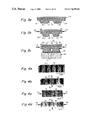
FIGS. 4a-d illustrate silicon surfaces selectively patterned with gold via mechanical deformation of a stamp in accordance with the invention;
FIGS. 5a-c illustrate a method of applying a patterned self-assembled molecular monolayer to a nonplanar surface in accordance with the invention;
FIGS. 6a-c illustrate nonplanar surfaces derivatized using the technique illustrated in FIGS. 5a-c;
FIG. 7 illustrates an optical fiber having an exterior surface patterned with a self-assembled molecular monolayer according to the invention;
FIGS. 8a-d illustrate a method of etching an article according to the invention;
FIGS. 9a-f illustrate a method involving lithographic molding of an article in accordance with the invention;
FIG. 10 is an atomic force microscope image of an article lithographically molded in accordance with the invention;
FIGS. 11a-f illustrate methods of forming flexible diffraction gratings in accordance with the invention, and a diffraction grating formed thereby;
FIGS. 12a-d illustrate a method of forming a flexible lens in accordance with the invention, and a lens formed thereby;
FIG. 13 illustrates a method for forming an optical element in accordance with the invention;
FIG. 14 illustrates apparatus for controlling the shape of a fluid on a surface in accordance with the invention;
FIGS. 15a and 15 b illustrate apparatus for controlling the shape of a fluid on two surfaces in accordance with the invention; and
FIGS. 16a-e illustrate a method of etching an article in accordance with one embodiment of the invention.
DETAILED DESCRIPTION OF THE INVENTION
Commonly-owned U.S. patent application Ser. No. 08/131,841, filed Oct. 4, 1993 by Kumar et al. and entitled “Formation of Microstamped Patterns on Surfaces and Derivative Articles”, now U.S. Pat. No. 5,512,131, issued Apr. 30, 1996, the entire content of which is incorporated herein by reference for all purposes, describes stamping, or microprinting, self-assembled monolayers onto surfaces, etching and plating such surfaces, assembling isolated regions of self-assembled monolayers exposing a particular chemical functionality, optionally surrounded by a self-assembled monolayer exposing a different functionality, and derivative articles. U.S. application Ser. No. 08/397,635, filed Mar. 1, 1995, co-pending and commonly-owned, is incorporated herein by reference for all purposes.
Referring to FIGS. 1a-d, a method for applying a self-assembled monolayer of a molecular species to a surface that involves controlled, reactive spreading of the species on the surface is illustrated schematically. The method results in two or more self-assembled molecular monolayers, or two or more regions of a single self-assembled molecular monolayer, that are very closely spaced on the surface. At FIG. 1a, a stamp 20 is illustrated having a surface 22 including a plurality of indentations 24 formed therein that form an indentation pattern. The indentations are contiguous with a stamping surface 26 that defines a stamping pattern. The stamping pattern includes closely-spaced features, that is, the indentations are closely-spaced and this results in the presence of closely-spaced protrusions, the outward-facing surfaces of which define the stamping surface 26.
Prior to microprinting, stamping surface 26, typically the entire surface 22 of the stamp, is coated with a molecular species 27. Molecular species 27 terminates in a functional group selected to bind to a particular material, and to form an ordered self-assembled monolayer thereupon. In the embodiment illustrated in FIGS. 1a-f, species 27 terminates in a functional group selected to bind to a surface 28 of an article 30, and to form a self-assembled monolayer on surface 28. A wide variety of species suitable as species 27 and surfaces suitable as surface 28, that is, species that terminate in a variety of functional groups, and surfaces to which they chemisorb, are described in application Ser. No. 08/131,841.
Stamp 20 of the present invention may be formed in a variety of ways. In one embodiment, stamp 20 is formed by contacting a mold surface with a hardenable material, typically a fluid, which serves as a precursor of the stamp. The fluid is hardened, for example by ionic, nonionic, or free-radical polymerization to form the stamp having a surface contacting the mold surface. A mold surface is advantageously selected to include at least one protrusion, and when the stamp is removed from mold surface, a stamp having a stamping surface including an indentation corresponding to mold surface protrusion results.
The particular material chosen for formation of stamp 20 should satisfy certain physical characteristics. Stamp 20 is advantageously chosen to be elastic, such that stamping surface 26 may very closely conform to minute irregularities in surface 28 of material 30 so as to completely transfer molecular species 27 thereto, and so as to be amenable to transferring SAMs of molecular materials to nonplanar surfaces. However, stamping surface 26 should not be so elastic that when it is pressed lightly against a surface, stamping surface features deform to the extent that blurring of molecular species 27 on material surface 28 results.
According to a preferred embodiment stamp 20 is formed from a polymeric material. Polymeric materials suitable for use in fabrication of stamp 20 may have linear or branched backbones, and may be crosslinked or noncrosslinked, depending upon the particular polymer and the degree of formability desired of the stamp. A variety of elastomeric polymeric materials are suitable for such fabrication, especially polymers of the general classes of silicone polymers, epoxy polymers, and acrylate polymers. Epoxy polymers are characterized by the presence of a three-member cyclic ether group commonly referred to as an epoxy group, 1, 2-epoxide, or oxirane. For example, diglycidyl ethers of bisphenol A may be used, in addition to compounds based on aromatic amine, triazine, and cycloaliphatic backbones. Another example includes the well-known Novolac polymers. Materials which may not be suitable for fabrication of stamping surface 26 according to preferred embodiments include polyethylene and polystyrene, which are generally too brittle, (not elastic enough), and polybutadiene, which is generally too elastic.
Examples of silicone elastomers suitable for use as stamp 20 include those formed from precursors including the chlorosilanes such as methylchlorosilanes, ethylchlorosilanes, and phenylchlorosilanes, and the like. A particularly preferred silicone elastomer is polydimethyl siloxane. Exemplary polydimethyl siloxane polymers include those sold under the trademark Sylgard by the Dow Chemical Company, Midland Mich., and particularly Sylgard 182, Sylgard 184, and Sylgard 186.
The ability to transfer SAMs to nonplanar surfaces is particularly advantageous in the preparation of microelectronic devices on curved surfaces, for example microcornections between various circuit regions, the connections conforming to a bend to conserve space in an overall circuit-containing region. Stamp 20 should also be formed such that stamping surface 26 comprises an absorbent material selected to absorb SAM-forming molecular species 27 to be transferred to a surface 28 to form a SAM thereon. Stamping surface 26 preferably swells to absorb molecular species 27, and/or to absorb molecular species 27 dissolved or suspended in a carrier such as an organic solvent. Such swelling and absorbing characteristics serve the important function of providing good definition of an isolated SAM on a surface. For example, if a dimensional feature of stamping surface 26 includes a substantially square-shaped feature, surface 26 should transfer molecular species 27 to surface 28 of material 30 so as to form SAMs mirroring the substantially square features of stamping surface 26, without blurring. Such blurring results from selection of a stamp which does not absorb molecular species 27, When such a stamp is employed, molecular species 27 resides as a fluid on stamping surface 26, rather than partially or fully within surface 26, and when stamping surface 26 contacts material surface 28, molecular species 27 is dispersed from under stamping surface 26. According to the stamp of the present invention, however, molecular species 27 is absorbed into stamping surface 26, and when stamping surface 26 contacts material surface 28, molecular species 27 is not dispersed, but binds to surface 28, and removal of stamping surface 26 from surface 28 results in well-defined SAM features.
Referring to FIG. 1b, stamp 20 is placed, in a predetermined orientation, adjacent to article 30 such that stamping surface 26 contacts article surface 28. Prior to, during, or shortly after stamping surface 26 is brought into contact with surface 28, a species 32 is applied to portions of surface 28 of article 30 that are not contacted by stamping surface 26. That is, surface 28 of article 30 includes at least a first portion 34 to which the self-assembled molecular species is transferred from the stamping surface, and at least a second portion 36, contiguous with first portion 34, to which is applied species 32.
Species 32 is incompatible with self-assembled monolayer-forming molecular species 27. As used herein, “compatible” is used to define species that have at least some mutual attraction, or at least are not mutually repulsive. For example, two polar species are compatible, and two nonpolar species are compatible. Miscible liquids, for example two different aqueous solutions, are compatible species. “Incompatible” is used herein to define species that are mutually repulsive to the extent that they are not miscible. For example, most organic liquids are incompatible with most aqueous solutions. Incompatible liquids will coexist separated by a phase boundary. An etchant that is inert with respect to a species such as a self-assembled monolayer is often inert with respect to the species since it is incompatible with the species. One of ordinary skill in the art can readily select such incompatible species, and a test to determine the compatibility or incompatibility of such species is routine to one of ordinary skill in the art. Species 32 is selected as one that does not chemisorb to surface 28. Thus, species 32 has a lesser affinity for surface 28 than does self-assembled monolayer-forming molecular species 27.
Typically, species 27 is a hydrophobic liquid or is carried in a hydrophobic liquid, as described in the above-referenced application Ser. No. 08/131,841. Species 27 also can be a hydrophilic liquid, or carried in a hydrophilic liquid. When species 27 (or a liquid in which species 27 is dissolved) is hydrophobic, species 32 is selected to be hydrophilic. When species 27 is hydrophilic, species 32 is selected to be hydrophobic. It is important only that species 27 and species 32 are incompatible.
For example, species 27 can include a hydrophobic long-chain alkyl group that terminates in a functional group that spontaneously chemisorbs to surface 28, and species 32 can be water or an aqueous solution. Alternatively, species 27 can be a long-chain alkyl group including sufficient heteroatoms to make species 27 hydrophilic and species 32 in that case can be a liquid that is sufficiently hydrophobic to be incompatible with species 27.
Referring now to FIG. 1c, The method involves allowing stamping surface 26 to remain in contact with surface 28 for a period of time sufficient to allow molecular species 27 to spread from portion 34 of surface 28 onto portion 36 of the surface. This occurs as species 27, transferred from stamping surface 26, has a greater affinity for surface 28 of article 20 than does species 32.
Stamp 20 is maintained in contact with article 30 for a period of time sufficient to allow species 27 to spread over surface 28 to a desired extent. The extent of spreading is, typically, approximately proportional to the time of contact between stamp 20 and article 30. Stamp 20 is advantageously allowed to contact article 30 for a period of time sufficient to allow species 27 to spread from each portion of stamping surface 26 toward an adjacent portion. In this way, species 27 is allowed to spread across surface 28 to form an increasingly narrow gap 38 (FIG. 1d) on surface 28. Gap 38 on surface 28 thus is not coated with species 27.
The presence of incompatible species 32 applied to portions of surface 28 that are not coated with species 27 facilitates the spreading of species 27 over surface 28 in a smooth, well-defined manner. That is, species 27 does not spontaneously chemisorb at random, isolated portions 36 of surface 28 between adjacent regions of stamping surface 26 via vapor transport or the like. The method of the invention results in very well-defined, very closely-spaced regions of species 27 on surface 28.
In FIG. 1d, stamp 20 has been removed from article 30, and a scanning electron micrograph of the surface of article 30 that has been patterned according to the embodiment illustrated is shown in FIG. 1e. In the embodiment illustrated, dimension 40, the width of indentations 24 between protrusions of stamp 20 that define stamping surface 26, is 3 microns, while the dimension of gap 38 between adjacent regions of self-assembled monolayer 27 that have spread toward each other is 0.1 micron.
FIG. 1e is a scanning electron micrograph of a silicon article 30, coated with a thin layer of gold, upon the surface of which species 27 has been allowed to spread in accordance with the method illustrated in FIGS. 1a-d. After removal of stamp 20, an etchant is applied to the surface. The etchant is not compatible with species 27, and species 27 is therefore undisturbed by the etchant. The etchant contacts surface 28 of the thin gold layer on silicon article 30 (not shown in FIGS. 1a-d) via gap 38, and dissolves the gold layer at gap 38. The result is illustrated in FIG. 1e, and an atomic force microscope image is shown in FIG. 1f. Following removal of the self-assembled monolayer of species 27, a thin gold layer that has been etched at gap 38, to form adjacent regions of gold on a silicon surface separated by approximately 0.100 micron, results.
FIGS. 1a-d illustrate an end view of a stamp 20 that includes a plurality of elongated, linear ridges 26, separated by recessed portions of the stamp. When such a stamp is brought into contact with a surface of an article in a first orientation, followed by removal of the stamp, rotation of the stamp through 90° relative to the surface of the article, and reapplication of the stamp to the surface, a grid pattern of species 27 on surface 28 results. During each application of the stamping surface to the surface of the article, the stamp can be held in contact with the stamping surface for varying periods of time, resulting in a grid of lines of molecular species 27 of varying width. Scanning electron micrographs of such a procedure are shown in FIGS. 2a-e. The surfaces shown in FIGS. 2a-e were derivatized by covering a silicon article with thin layer of gold, applying species 27 to the gold surface via microprinting with a microstamp, and contacting exposed portions of the gold surface (those portions not covered by the self-assembled monolayer) with an etchant that is not compatible with species 27 and that dissolves gold. The etchant is thus inert with respect to species 27. For each of FIGS. 2a-e, stamp 20 was applied to the surface in a first orientation for a first period of time (“1st printing”), and applied to the surface in a second orientation rotated 90° from the first orientation for a second period of time (“2nd printing”). The time that stamping surface 26 was allowed to contact surface 28, for each printing step, is listed beside each figure. Control of the length and width of exposed portions of silicon results. Dark portions 41 are exposed regions of silicon following etch, and light regions 42 are the self-assembled monolayer on the gold surface. The procedures described with respect to FIGS. 1 and 2 are described in greater detail below in Example 1.
Referring now to FIGS. 3a-c, a method for applying a self-assembled monolayer of a molecular species to a surface of an article according to another embodiment of the invention is illustrated, in which a stamp is deformed prior to and/or during transfer of the species to the surface. FIG. 3a illustrates, schematically, an end view of a portion of a stamp 20 including a surface 22 that includes a stamping surface 26 separated by indentations 24. Stamp 20 is deformed prior to and/or during transfer of a self-assembled monolayer-forming molecular species 27, which coats stamping surface 26 (typically coating the entire surface 22 of stamp 20), to surface 28 of article 30. When stamp 20 is deformed prior to transfer, it generally is compressed by applying to the stamp forces parallel to the stamping surface. That is, with reference to FIG. 3b, force is applied to the stamp in the direction of arrows 44. This results in reduction in the dimension of individual portions of stamping surface 26 along the direction of the application of force, as well as reduction of the dimension of indentations 24 in the same direction. That is, features of stamping surface 26 are reduced in size, and in spacing from each other, in the direction parallel to the application of force.
When stamping surface 26 (generally the entire surface 22) of stamp 20 is coated with molecular species 27 (not illustrated in FIG. 3b) and allowed to contact surface 28 of article 30, a self-assembled monolayer is formed on surface 28 that includes regions having lateral dimensions that correspond approximately to the dimension of features of stamping surface 26. Thus, when stamp 20 is deformed as illustrated in FIG. 3b, self-assembled monolayers, or a self-assembled monolayer having separate regions, is formed on a surface with dimensions smaller than those that would be achieved typically when the stamp is not deformed. Referring to FIG. 3c, stamp 20 is illustrated with stamping surface 26 in contact with surface 28 of article 30, where the stamp has been deformed by applying a force perpendicular to stamping surface 26, that is, perpendicular to surface 28 of article 30. This perpendicular force is represented by arrows 46, and can be applied independently of, or in combination with, a compressive force on the stamp that is parallel to the stamping surface and that is represented by arrows 44. Application of a compressive force represented by arrows 44 and/or a perpendicular force represented by arrow 46 will result in reduced feature sizes of species 27 on surface 28. When a force perpendicular to stamping surface 26 is applied, as represented by arrows 46, gap 38 between regions of species 27 on surface 28 is smaller than the dimension of indentations 24 between regions of stamping surface 26. Thus, the stamp is deformed as illustrated in FIG. 3c where the distance between adjacent regions of stamping surface 26 is lessened.
Although only compressive forces are described with respect to deformation of stamp 20 during microprinting, stamp 20 can be deformed by stretching, as well.
Referring now to FIGS. 4a-c, scanning electron micrographs showing surfaces derivatized via microstamp deformation are shown. The figures represent printing using a microstamp deformed by compressing the stamp by applying force parallel to the stamping surface (arrows 44 of FIG. 3b), independently along perpendicular axes. A silicon article covered with a thin layer of gold was provided, with a self-assembled monolayer applied to the gold surface. Gold was etched from regions to which the monolayer was not applied. In FIGS. 4a-c, light regions 48 represent the self-assembled monolayer on the thin gold film on silicon, and regions 50 represent exposed silicon surface from which gold has been etched. A stamp used to apply a self-assembled monolayer to the gold surface was fabricated generally as described below in example 1, and included a surface including indentations represented by regions 50, defining a stamping surface represented by regions 48. FIG. 4a illustrates a surface to which a self-assembled molecular monolayer was applied from the stamp without deformation of the stamp, followed by etching of gold from regions to which the self-assembled monolayer was not applied. In FIG. 4b, the stamp was compressed along an axis parallel to the stamping surface, by applying force as illustrated by arrows 52. In FIG. 4c, the stamp was compressed along an axis parallel to the stamping surface, by applying force in the direction of arrows 54, perpendicular to the compressive force applied in FIG. 4b. In FIG. 4d, the stamp was compressed along two perpendicular axes, both axes being parallel to the stamping surface, by applying force as illustrated by arrows 52 and 54.
Mechanical deformation of a stamp as described above and illustrated in FIGS. 3a-c and 4 a-d can be employed in conjunction with controlled reactive spreading of molecular species as described above and illustrated in FIGS. 1a-f and 2 a-e. That is, a stamp can be deformed, and held in contact with a surface to transfer a self-assembled monolayer thereto, while applying, to regions of the surface not contacted by the stamping surface, a species that is not compatible with the molecular species that forms the self-assembled monolayer. This procedure, as described above, advantageously includes allowing the stamp to remain in contact with the surface for a period of time sufficient to allow the molecular species to spread accordingly.
All of the embodiments of the invention described thus far can be used in conjunction with methods of etching and/or plating a surface as described below, and as described in U.S. application Ser. No. 08/131,841, referenced above.
Referring now to FIGS. 5a-c, a method of transferring a patterned, self-assembled monolayer to a nonplanar surface is illustrated schematically. As used herein, the term “nonplanar” is meant to define a surface, at least a portion of which has a radius of curvature. The method that is illustrated involves rolling a nonplanar surface, that is, the surface of a nonplanar article, over a stamping surface of a stamp carrying a self-assembled monolayer-forming molecular species. The surface that is rolled over the stamp can be that of a cylindrical article, a spherical article, or any other article having a nonplanar surface. Stamp 20 in this embodiment is flat, that is, stamping surface 26 defines portions of a plane. In other embodiments (not illustrated), the stamp is nonplanar, that is, formed such that the stamping surface does not define a plane, or is a flexible, planar stamp that is deformed so as to be nonplanar.
Referring to FIG. 5a, an article 30 has a nonplanar surface 28. According to the embodiment illustrated, article 30 is silicon dioxide, coated with a thin layer of titanium (not shown), which is coated with a thin layer of 31 of gold. Stamping surface 26 of stamp 20, and generally the entire surface 22 of stamp 20 is coated with a self-assembled monolayer forming molecular species 27. Article 30 is caused to roll over stamping surface 26, for example, by placing article 30 between stamping surface 26 and a member 56, moving stamp 20 and member 56 relative to each other along parallel planes in opposite directions, to cause the article to roll over the stamping surface. Member 56 can be made of any material that will not disrupt or contaminate surface 28, and preferably a material that will not disrupt a self-assembled monolayer formed on surface 28. Member 56 can be made of the same material from which stamp 20 is made.
As used herein, the term “roll” refers to action in which a first surface is maintained in constant contact with a second surface (for example, surface 28 of article 30 and stamping surface 26, respectively), but only a portion of each surface is in contact with only a portion of the other surface at any given time, and the portion of each surface that is in contact with the portion of the other surface changes continuously.
Referring now to FIG. 5b, article 30 is illustrated after having been rotated through approximately 260° of rotation on stamping surface 26. As a result, individual, isolated regions of a self-assembled monolayer of molecular species 27 are formed on surface 28 of article 30 around approximately 260° of the surface, corresponding to individual regions of stamping surface 26.
When this article is subject to a cyanide etch, as described above and described below in Example 2, gold that is not protected by molecular species 27 is removed, as illustrated in FIG. 5c, exposing the thin layer of titanium (titanium dioxide) at regions not covered by the self-assembled monolayer. A nonplanar article, such as that illustrated in FIGS. 5a-c, can be etched in accordance with embodiments of the invention described in application Ser. No. 08/131,841, and described below.
Referring now to FIGS. 6a-c, nonplanar articles covered by a thin layer of gold, to which patterned, self-assembled monolayers have been applied, followed by etching of gold from the surface at regions not protected by the self-assembled monolayer, are illustrated. In each case, the nonplanar article was rolled across a substantially planar stamping surface including a stamping pattern (pattern formed by stamping surface 26). The stamping pattern includes features similar to those found in typical electronic circuitry. Gold was etched as described above and described below in Example 2.
FIG. 6a illustrates a 1 mm diameter glass capillary coated with a thin layer of gold, which was printed according to the pattern illustrated, followed by removal of gold from the areas not covered by a self-assembled monolayer. FIGS. 6b and 6 c show views, at different magnification, of a lens having a 5 cm radius of curvature, coated with a thin film of gold, microprinted and etched as described herein. In FIGS. 6a-c, light regions are gold covered with a self-assembled monolayer, and dark regions are glass.
FIG. 7 illustrates an etched optical fiber (glass). The fiber was coated with approximately 200 angstroms of titanium, which is coated with approximately 200-300 angstroms of gold. The exterior surface of the fiber was microstamped with hexadecanethiol, which served as a resist in a subsequent etch. The etch step removed the gold layer not covered by the self-assembled monolayer, and the light regions represent a self-assembled monolayer of hexadecanethiol on gold, while the dark regions represent the exterior surface of the optical fiber covered with titanium.
In some instances, when it is desirable to use a self-assembled monolayer as a resist in an etching process, the self-assembled monolayer may not effectively resist the etchant. The present invention provides, for such a situation, a protecting species positioned on a self-assembled monolayer. The protecting species is inert with respect to the etchant by, for example, being incompatible with the etchant. The protecting species is compatible with the exposed functionality of the monolayer. For example, silicon coated with a thin, thermally-formed layer of silicon dioxide, is conveniently etched using hydrofluoric acid/ammonium fluoride. Then, silicon dioxide that has not been etched can serve as a resist for the etching of silicon and, for example, potassium hydroxide/isopropanol. However, many self-assembled molecular monolayers will not withstand (are not inert with respect to) the etchant used to remove silicon dioxide. The present invention provides a protecting species that will resist the etch. Many articles have a native layer of oxide. For example, silicon has a native layer of oxide that is approximately 5 nanometers thick. Generally, such a native layer will not serve as an effected resist. A thermally-formed oxide layer will generally have a thickness of approximately 0.2 microns. Articles having thermally formed layers of oxide thereon are readily available commercially. For example, silicon including a thermally-formed layer of silicon dioxide thereon is available from Silicon Sense Corporation, Nashua, N.H.
Referring to FIGS. 8a-d, a process for etching silicon in accordance with the present invention is illustrated. FIGS. 8a-d are schematic illustrations of the process.
Referring to FIG. 8a, a silicon article 60 includes, on its surface 62, a thermally-formed layer 64 of silicon dioxide, having a surface 66. A self-assembled monolayer 68 (for example alkylsiloxane) is patterned onto the surface 66, using any method described herein or other method known to those of skill in the art. Referring to FIG. 8b, molecular species 68 is coated with a protecting species 70 that is compatible with the molecular species. That is, molecular species 68 exposes a chemical functionality that is compatible with the protecting species. If the chemical functionality exposed by molecular species 68 is significantly polar, protecting species 70 should be significantly polar. Protecting species 70 can be a liquid, and can be a polymerizable species that is polymerized prior to application of the etchant.
Referring to FIG. 8b, following application of protecting species 70 to molecular species 68, a first etchant (for example HF/NH4F, not shown) is brought into contact with exposed portions of surface 66, whereupon the portions of silicon dioxide resist layer 64 that are not covered by self-assembled monolayer 68 and protecting species 70 are dissolved, exposing corresponding portions of surface 62 of silicon. Subsequently, a silicon etch (for example, KOH/I—PrOH) is added, and the silicon dioxide that had been covered by the self-assembled monolayer and protecting species 70 acts as a resist for a silicon etch.
Referring to FIGS. 8a-d, according to one embodiment an etchant is used that is destructive of a self-assembled monolayer, and in this embodiment a protecting species is advantageously used. According to another embodiment, a resist is used that can be etched with an etchant that does not destroy a self-assembled monolayer, and in this embodiment the protecting species need not be used. An example of the latter embodiment involves etching a silicon article coated with a thin film of gold. The gold in that embodiment defines a resist having a surface, to which can be transferred a self-assembled monolayer in a pattern, the self-assembled monolayer being contiguous with exposed portions of the gold surface in a second pattern. The surface of the article (the surface of silicon) can be exposed by removing gold from the surface (according to the second pattern) by contacting the exposed portions of gold with an species that reacts chemically with gold and that is inert with respect to the self-assembled monolayer. This exposes the surface of the article, according to the second pattern. Then, the exposed surface of the article can be etched, if the etchant is inert with respect to the resist (gold).
In an alternative method, a self-assembled monolayer can be applied to the surface according to a first pattern, exposing a first functionality. The remaining portions of the surface are filled in with a self-assembled monolayer of a second species exposing a second chemical functionality. A protecting species that is compatible with the second chemical functionality is applied to the surface, and adheres to the self-assembled monolayer of the second species, protecting a pattern on the surface that is complementary to the first pattern, that is, protecting regions of the surface that do not include the first pattern.
A variety of materials can be deposited on the surface of the article to serve as a resist. For example, thin layers of metal such as gold, silver, copper, nickel, cadmium zinc, palladium, platinum, iron, chromium, alloys of these and the like can be deposited by those of skill in the art. Etchants that will dissolve resist such as these should be selected to oxidize atoms from the surface, and to include ligands, such as chelating or coordinating ligands, that will dissolve the oxidized atoms removed from the surface. Etchants or such resists are known to those in the art, and include aqueous etches such as ferricyanide etch, thiosulfate etch, thiourea etch, and the like. Often an adhesive layer is advantageously placed upon the surface of the article prior to application of the resist layer. The adhesive layer generally will be at least ten angstroms thick, and may be much thicker. The thickness of the resist layer, if it is a metal such as gold, is generally approximately 1000 angstroms. However, the resist can be from about 50 angstroms to many thousands of angstroms, depending upon the application.
Many etchants will not attack a self-assembled monolayer on a surface, thus the self-assembled monolayer can be printed on such a surface, the resist can be etched from regions where the self-assembled monolayer does not lie, and the article can be etched at regions where the resist has been removed. Some etchants, however, that are particularly reactive, for example, aqua regia, carbon tetrafluoride, potassium iodide-iodine and the like, may harm self-assembled monolayers in some circumstances. Etchants that are particularly destructive of self-assembled monolayers are useful, in some circumstances, to etch certain resists from the surface of articles. For example, etching silicon dioxide from the surface of silicon requires etchants that generally at least partially destroy self-assembled monolayers.
According to one embodiment, protecting species 70 is applied to self-assembled monolayer 68 in the following manner. A bath of a fluid that is incompatible with the exposed ftunctionality of self-assembled monolayer 68 is prepared, including a layer of fluid protecting species (or protecting species precursor) over the incompatible fluid. The article illustrated in FIG. 8a is passed through the region of the protecting species, which adheres to self-assembled monolayer 68, and passed into the fluid that is incompatible with the self-assembled monolayer. Where the protecting species is a fluid that is hardened, for example via polymerization, polymerization may take place in the bath, or the article may be removed from the bath prior to polymerization.
The invention also provides a method for making an article, which utilizes any of the above-described, or known, methods for etching a surface. The etched surface serves as a template for the article according to this method of the invention. The method involves etching a pattern into a surface of a template and molding an article on the surface of the template. An article, formed by molding on the surface of a template, results. An example of such a process is illustrated schematically in FIGS. 9a-f. FIG. 9a illustrates a silicon article 60 including a surface 62 coated with a layer of resist 64 having a surface 66. In the embodiment illustrated, the resist is a thin layer of gold over titanium (100/1000 angstroms). A self-assembled monolayer-forming molecular species 27 is applied to surface 22 (in particular, stamping surface 26) of a stamp 20. Referring to FIG. 9b, a self-assembled monolayer of molecular species 27 is thereby transferred to surface 66 of resist 64 in a pattern corresponding to the pattern of stamping surface 26 of stamp 20. Self-assembled monolayer 27 can be applied to surface 66 according to methods described above and illustrated with reference to FIGS. 1a-5 c. An etchant that is chemically reactive with a resist and that is inert with respect to the self-assembled monolayer is brought into contact with exposed portions of the resist surface (portions not covered by self-assembled monolayer 27). The resist is etched, exposing portions of surface 62 of article 60 (FIG. 9c). Subsequently, article 60 is etched by applying to the exposed portions of surface 62 a second etchant that reacts chemically with article 60 and that is inert with respect to resist 64. The result, as illustrated in FIG. 9d, is a pattern etched into article 60, which pattern corresponds approximately to a pattern of gaps between closely-spaced regions of self-assembled monolayer 27 (FIG. 9a). Removal of resist 64 and self-assembled monolayer of molecular species 27 (if it has not yet been removed) results in a patterned article 60 that is useful for many purposes. One useful purpose, in accordance with the invention, involves using the etched surface of article 60 as a template for fabrication of an article. In FIG. 9e, an article has been molded onto surface 62 of article 60. In particular, a hardenable fluid 72, such as a prepolymeric solution, is applied to surface 62 of article 60 and hardened (polymerized, for example), to form article 74. Article 74 then is removed from surface 62 of article 60, and as illustrated in FIG. 9f includes a surface 76 that corresponds to surface 62 of article 60. Article 74 can be a stamp used for microprinting, as described above. Alternatively, article 74 can be used as an optical element as described below and as described in U.S. application Ser. No. 08/131,841, referenced above.
An advantage to forming article 74 from a substrate etched lithographically as illustrated in FIGS. 9a-f, from a self-assembled monolayer applied by a microstamp, is that the surface of template 60, if it is an oriented crystal, can be etched to form grooves or pits that form an approximate ridge or point at their deepest portions. The method preferably uses a template that can be etched anisotropically. Generally, any material that forms an oriented crystal can be etched anisotropically using etchants available to those of skill in the art. Such a material can be etched such that a feature etched into its surface has a dimension much smaller than the dimension of the region at the surface of the material to which etchant is applied. For example, silicon is etched anisotropically resulting in grooves that become narrower with depth. An article molded on such a template will include protrusions that decrease in size in a direction away from the center of the article.
As discussed, according to one embodiment a thin film of a resist, such as gold, coats the surface of the article that is etched. According to another embodiment, the article includes an oxide layer on its surface that can serve as a resist. For example, silicon, titanium, zirconium, germanium, aluminum, copper, and other articles known to those of skill in the art would include a surface layer of oxide that can serve as a resist, or a layer of oxide that can serve as a resist can be grown at the surface by, for example, heating the article in the presence of oxygen. Other articles that can be used in accordance with the invention and that can be coated conveniently with a thin layer of resist are semiconductors including gallium arsenide, indium phosphide, cesium chloride, diamond and the like. These and other materials known to those of skill in the art form oriented crystals that can be etched anisotropically. The articles discussed above including layers of oxide can define articles including resist layers, as described above with reference to FIGS. 8a-d.
FIG. 10 is an atomic force microscope image of a polydimethyl siloxane (PDMS) article 74 formed according to the method illustrated with reference to FIGS. 9a-f. According to embodiments in which the article is a microstamp, stamping surface 81 include features having a latera dimension of approximately 0.100 micron or less. Similar articles can be fabricated including, rather than linear ridges defining stamping surface 81 as illustrated in FIG. 10, small, isolated projections that define stamping surface 81, which projections approximate a point. The projections can be in, for example, an ordered array. In one embodiment the stamping surface comprises at least one resolved feature providing stamping resolution of less than about 100 microns. In another embodiment, the stamping surface comprises at least one resolved feature providing stamping resolution of less than about 10 microns, and preferable less than about 1 micron.
According to another embodiment of the invention a method is provided for simultaneously writing, on a surface of an article, at least two self-assembled monolayer patterns. The method involves coating a stamping surface of a microstamp with a self-assembled monolayer-forming species, contacting an article surface with the stamping surface, and moving the stamping surface relative to the article surface to write on the surface. For example, a stamp that includes a plurality of protrusions that, at their terminus (stamping surface), approximate points can be used to write, simultaneously, a plurality of lines on an article surface. Such lines can define a pattern that forms the basis of a corresponding electronic circuit, an etched region, or other feature as described in accordance with the invention or apparent to those of ordinary skill in the art. A stamp with such features can be obtained conveniently by patterning a surface of an article that can be anisotropically etched with resist, forming on the surface of the resist a self-assembled monolayer in a grid pattern while leaving isolated regions of the surface of the resist free of self assembled monolayer, etching the resist that is not covered by the self-assembled monolayer, and etching the surface of the article anisotropically to form a plurality of indentations that become narrower with depth until they approximate a plurality of points. This serves as a template for a stamp that includes a plurality of protrusions that terminate in approximate points at their stamping surface (or writing surface).
As used herein, the term “writing” is given its ordinary meaning. In the context of a self-assembled monolayer, this means forming a pattern of a self-assembled monolayer on a surface not instantaneously, but progressively, in a manner analogous to the way ink is applied to paper when writing with a pen. In this way, a method is provided that involves writing on a surface of an article simultaneously at least two separate lines of a self-assembled monolayer-forming species.
According to embodiments of the present invention in which a self-assembled monolayer is formed on silicon dioxide or glass, advantage can be achieved in aspects of the invention that involve etching, and aspects that involve preparation of surfaces of interest in biological arenas. In aspects that involve etching, when silicon dioxide is used as a resist layer on silicon, advantage in the etching of silicon is achieved as discussed above. Additionally, bulk silicon dioxide or glass can be etched by patterning a self-assembled monolayer of alkylsiloxane, such as octadecylsiloxane, on a surface thereof, optionally coating the self-assembled monolayer with a protecting species, and contacting the surface with an etchant that etches the silicon dioxide or glass.
According to aspects of the invention involving the preparation of surfaces of biological interest, a surface such as a silicon dioxide or glass slide or petri dish can be patterned with a self-assembled monolayer of alkylsiloxane that exposes a chemical functionality of biological interest, facilitating studies at that surface. For example, a self-assembled monolayer of alkylsiloxane terminating in a cytophilic ftmctionality can be patterned onto a silicon dioxide or glass surface in accordance with the invention, followed by adherence or immobilization of a cell or cells to the cytophilic functionality. Biological, specifically cytophilic, functionalities in association with self-assembled monolayers are described in copending, commonly-owned application Ser. No. 08/131,841 and in an article entitled “Engineering Cell Shape and Function”, by Singhvi, R., et al. Science, 264, 696 (1994), both incorporated herein by reference. This article describes the formation of islands of self-assembled monolayer terminating in a non-polar functionality (—CH3) surrounded by regions of polyethylene glycol-terminating self-assembled monolayer. The non-polar terminal functionality of the islands is protein adherent, while the polyethylene glycol functionality is not protein-adherent. Exposure of a surface derivatized as such to a protein matrix such as the purified extracellular matrix protein laminin results in cytophilic, protein-coated islands surrounded by cytophobic regions. Exposure of this surface to cells results in cell attachment preferentially to the adhesive (cytophilic), laminin-coated islands and the cells are prevented from extending onto surrounding non-adhesive (cytophobic) regions. Alternatively, a surface derivatized as described above with a patterned, self-assembled monolayer terminating in non-polar, such as methyl, functionality can be contacted with a cell or cells without first treating the surface with a protein matrix such as laminin. According to some embodiments, the cell or cells will secrete a protein matrix such as laminin that will coat the exposed non-polar functionality, and the cell or cells then will adhere thereto.
A variety of cell studies can thereby be conducted that involve immobilization of a cell or cells on one or more islands. Procedures involving cell growth, differentiation, culturing, and the like can be tailored by varying the size and/or shape of islands, spacing between islands, and the like. Those of ordinary skill in the art will appreciate that alkylsiloxane-based self-assembled monolayers on glass or silicon dioxide can be prepared that terminate in a variety of chemical or biochemical functionalities amenable to attachment of biological species such as antibodies, antigens, haptens, proteins, sugar and other carbohydrates, etc., prepared in accordance with methods of patterning described herein. Functionalities such as chelates, etc. as described in commonly-owned, copending U.S. patent application Ser. No. 08/312,388 (Bamdad, et al.), incorporated herein by reference, can be provided at the exposed end of molecules making up self-assembled monolayers patterned on glass or silicon dioxide as well.
According to some embodiments of the invention the above-described techniques involving patterning glass or silicon dioxide can be applied to other polar surfaces including polar polymeric surfaces such as oxidized polyethylene or polystyrene. According to these embodiments alkylsiloxane can be patterned onto a polymeric surface oxididized for example via plasma etch to expose polar functionalities such as hydroxyl, carboxylic acid, aldehyde, or the like. These surfaces can form the basis for all embodiments of the invention described herein, including the biological aspects described above.
Patterning of alkylsiloxane onto glass, silicon dioxide, or polar polymeric surfaces can be carried out according to chemistry known to those of skill in the art. For example, trichlorosilane or trialkoxysilane such as triethoxysilane, when applied to these surfaces in essentially any solvent in which they can be carried (such as water, hexane, toluene, and the like) will form alkylsiloxane on that surface.
The techniques described above involving patterning of alkylsiloxane on glass, silicon dioxide, or polar polymeric surfaces can be carried out on planar or non-planar surfaces, as described herein, and can be combined with techniques described herein involving allowing alkylsiloxane or its precursor to spread onto the surface while contacting the surface simultaneously with a species that is not compatible with the alkylsiloxane or precursor, and involving deforming a stamp from which the alkylsiloxane or precursor is transferred, or both.
The present invention also provides a variety of optical elements and devices. One such element is a diffraction grating that can be formed as described above with respect to article 74 (FIG. 9f) or as described in U.S. application Ser. No. 08/131,841, referenced above, in which a variety of optical elements including an optical switch are described. According to a preferred embodiment of the invention, a reflective liquid, such as a liquid metal, is brought into contact with a surface that correlates to a surface of an optical element, and a surface of the liquid metal is thereby formed into an optical surface. A method for making such an article is illustrated schematically in FIGS. 11a-f. In FIG. 11a, a template 78, for example a commercial diffraction grating, is provided. Template 78 can be mounted on a support 80, for example a glass slide. At FIG. 1b, a fluid precursor 82 is brought into contact with optical surface 79 of template 78. In the embodiment illustrated, fluid precursor 82 is a prepolymeric solution of polydimethylsiloxane, and is contained in a container 84, for example a petri dish. Fluid precursor 82 is allowed to harden in contact with the optical surface 79. Where precursor 82 is a prepolymer fluid, it is polymerized. When hardened, an article 86 that results from hardening of the fluid precursor is removed from template 78 (FIG. 11c), and can be removed from container 84 (FIG. 11d; alternatively, article 86 can remain in container 84 during application of a liquid metal to surface 88, and optional encapsulation, discussed below with reference to FIGS. 11e and f). The resultant article 86 (FIG. 11d) has an optical surface 88 that corresponds to optical surface 79 of the template. Article 86 is preferably transparent, and is a transparent elastomeric diffraction grating according to a preferred embodiment.
According to a preferred embodiment, optical surface 88 of article 86 is contacted with a liquid metal 90, for example gallium, mercury, or other liquid known to those of skill in the art (FIG. 11e). Liquid metal 90 includes a surface 92 that is in contact with and correlates to surface 88 of article 86, and surface 92 of liquid metal 90 is thereby formed into a diffraction grating. If article 86 is transparent, electromagnetic radiation can be directed through article 86 at surface 92, and diffracted (FIG. 11e). After liquid metal 90 is brought into contact with article 86 so that a surface 92 of liquid 90 contacts and correlates with surface 88 of article 86, liquid metal 90 can be encapsulated by coating exposed surfaces of the liquid metal with a hardenable fluid, preferably the same fluid as fluid precursor 82, and the fluid allowed to harden. The result, as illustrated in FIG. 11f, is an optical element 93 that is a liquid metal having a surface 92 that is an optical surface, which liquid metal is encapsulated in a transparent article 86.
According to an embodiment in which article 86 is flexible, optical surface 92 of liquid metal 90 can be deformed. For example, surface 92 can be compressed, elongated or bent. Where article 86 is an elastomer, surface 92 can be repeatedly elongated and bent. Thus, where the electromagnetic radiation is directed at surface 92 and diffracted, the pattern of diffraction can be adjusted, that is, changed, by manipulating optical element 93, for example by stretching it.
The method and article described above with reference to FIGS. 11a-f can be used in conjunction with any optical element having a reflective surface, such as diffraction gratings including holographic gratings, blaze gratings (illustrated in FIGS. 11a-f), and the like. For example, a concave mirror can be formed according to one embodiment, and this is described with reference to FIGS. 12a-d. At FIG. 12a a template 94 having an optical surface 95, for example a glass plano-concave lens, is immersed in a fluid precursor 82, for example polydimethylsiloxane. Precursor 82 is hardened and template 94 is removed, and an article 96 having an optical surface 98 that corresponds to optical 95 of template 94 remains (FIG. 12b). Referring to FIG. 12c, a liquid metal 90 is placed in contact with optical surface 98 of article 96, thus an optical surface 100 is formed on liquid metal 90, defining an optical element 102. According to one embodiment article 96 is flexible. According to a preferred embodiment article 96 is an elastomer. Article 102 according to this embodiment includes an elastomer 96 including a void 104 having a convex or concave surface (convex surface 100 as illustrated) and a liquid metal 90 adjacent the surface of the void, the liquid metal having an optical surface 100 (a concave mirror surface is illustrated that corresponds to the concave optical surface 95 of template 94).
Optical element 102 can be used to focus electromagnetic radiation directed at optical surface 100 of liquid metal 90 and allowed electromagnetic radiation to reflect from the optical surface. According to an embodiment in which article 96 is flexible, article 96 can be adjusted, thereby adjusting optical surface 100 of liquid metal 90 and adjusting the focus of the electromagnetic radiation. According to a preferred embodiment in which article 96 is an elastomer, this can be done repeatedly.
Referring to FIG. 12d, optical element 103 is illustrated. Optical element 103 results from complete encapsulation of liquid metal 90 by article 97, which can be formed by taking steps as described above with respect to FIG. 11f. In the embodiment illustrated in FIG. 11f, liquid metal 90 completely fills void 104 in article 96.
Referring now to FIG. 13, a method of making an optical element is illustrated schematically. The method involves providing a substrate 106 that has, on a surface 108 thereof, a self-assembled monolayer 110 exposing a first chemical functionality. Monolayer 110 is formed in a predetermined shape on surface 108 that corresponds to a shape desired for one portion of the surface of the optical element. A fluid precursor 112 of the optical element then is placed upon monolayer 110, and a surface 114 of fluid precursor 112 is contacted with a fluid 116 that is incompatible with the fluid precursor 112. Alternatively, the incompatible fluid 116 can first be applied to surface 108 of article 106 (and monolayer 110), and fluid precursor 112 then can be applied to monolayer 110, for example using a pipet 118. Portions of surface 108 of article 106 that are not covered with monolayer 110 do not attract fluid precursor 112. If such portions of surface 108 are attractive to fluid precursor 112, a self-assembled monolayer 120 can be formed around self-assembled monolayer 110, isolating monolayer 112, that exposes a chemical functionality that does not attract precursor 112.
When precursor 112 is polydimethylsiloxane that is polymerized to form an optical element that is a piano-convex lens, self-assembled monolayer 110 can be formed from a molecular species terminating in a non-polar functionality, for example hexadecanethiol. In this case, if surface 108 is not sufficiently repulsive of fluid precursor 112, then the remaining portions of surface 108 can be coated with a self-assembled monolayer of a species terminating in a polar functionality, for example a long-chain thiol terminating in a carboxylic acid. This arrangement can be used when surface 108 is a gold surface. Other combinations of surfaces and functional groups that adhere to surfaces are described in application Ser. No. 08/131,841, and/or are known to those with skill in the art.
The present invention also provides a method for controlling the shape of a liquid, for example a fluid precursor of an optical element. Referring to FIG. 14, the method involves providing a supporting, electrically conductive surface 120. Surface 120 can, for example, be an exposed surface of a thin, transparent gold film 121 on a transparent (e.g. glass) support 122. A self-assembled monolayer is applied to a region 124 of surface 120 and a fluid 126 that is attracted to the chemical functionality exposed by the self-assembled monolayer is applied to the self-assembled monolayer. If surface 120 is not repulsive of fluid 126, then the portion of surface 120 not covered by the self-assembled monolayer can be covered by a self-assembled monolayer exposing a chemical functionality that is repulsive of fluid 126. An electrolyte fluid 128 that is not compatible with fluid 126 is placed over fluid 126, and an electrical circuit including surface 120 and electrolyte 128 is arranged. For example, a reference electrode 130 and a counter electrode 132 can be immersed in electrolyte 128, and surface 120 can define a working electrode, the working, counter, and reference electrodes being controlled by potentiostat 135. By altering the electrical potential at surface 120, the contact angle formed by liquid 126 at surface 120 changes. The change in contact angle is dependent upon the electrical potential. According to one embodiment, the self-assembled monolayer at region 124 is caused to desorb and resorb, during change in electrical potential, at the outermost point of contact between fluid 126 and the surface selectively, and this causes the contact angle between the fluid and the surface to change.
In this way, liquid 126 can be used as a lens that can be focused depending on the electrical potential of surface 120 relative to reference electrode 130. A source of electromagnetic radiation 134 can direct electromagnetic radiation at fluid 126, which electromagnetic radiation can be focused and utilized by a sensor or other electromagnetic radiation-receiving apparatus 136. If fluid 126 is a hardenable fluid, it can serve as a precursor of a solid lens, and adjusting the electrical potential between surface 120 and reference electrode 130 can adjust the focal length of fluid 126, followed by hardening of fluid 126 to produce a lens 126 having a focal length that has been set by adjusting the potential at surface 120 during lens formation. Hardenable fluids useful as fluid 126 include those described above with respect to formation of microstamps and optical elements, and include generally any hardenable fluid that is incompatible with a suitable electrolyte, and that can be placed upon an exposed surface of a self-assembled monolayer.
When a self-assembled monolayer exposes a redox functionality, the species that forms the spacer portion of the self-assembled monolayer-forming species can advantageously be selected as one that has a reasonably good electron transfer function, for example polyenes, poly-ynes, polyaromatics, and the like can be selected.
According to another embodiment, region 124 of surface 120 (or the entire surface 120) is covered with a self-assembled monolayer exposing a redox functionality. Examples of suitable redox functionalities include ferrocene, quinone, thiophene, pyrrole, and the like. The redox state of the exposed chemical functionality of the self-assembled monolayer can be controlled, which can control the contact angle of a fluid 126 at the surface of the self-assembled monolayer.
While the arrangement in FIG. 14 involves an electrolyte contacting surface 120, surrounding fluid 126, and contacting the working and reference electrodes, according to an embodiment in which fluid 126 is an electrolyte, the working and counter electrodes can contact fluid 126 directly. In this embodiment, electrolyte 128 is not necessary if not needed to aid in the formation of the shape of fluid 126.
In the embodiment described with reference to FIG. 14, where fluid 126 is an organic fluid, it may be conveniently applied to region 124 of surface 120 as follows: an aqueous fluid 128 is prepared, and a layer of organic fluid 126 is placed on top of aqueous solution 128. Article 122 is passed through the layer of organic fluid 126, whereupon some of fluid 126 adheres to region 124 of surface 120, and into aqueous solution 128.
In FIG. 14, one article only is formed from fluid 126. However, a plurality of articles on a plurality of isolated regions of surface 120 can be fabricated, and/or used as individual optical elements as illustrated.
According to another embodiment similar to that illustrated in FIG. 14, a plurality of articles are formed on a surface 120 without the use of electrochemistry. A self-assembled monolayer including an isolated region exposing a particular chemical functionality, or an isolated region of a self-assembled monolayer exposing a chemical functionality surrounded by a surface free of self-assembled monolayer, can be passed through an organic fluid layer 126 on top of an aqueous layer 128, whereupon portions of fluid 126 adhere to compatible portions of the self-assembled monolayer, as illustrated in FIG. 14. Fluid 126 can then be hardened, for example via curing, under an aqueous solution, or the article can be removed and fluid regions 126 can be cured.
The present invention also provides a method of forming an article that includes providing a precursor of the article in contact with at least two discreet self-assembled monolayer regions. Referring to FIGS. 15a and 15 b, a first article 140 and a second article 142 are illustrated schematically. Article 140 includes a thin layer of a conductive species 144 on one of its surfaces and article 142 includes a thin layer of a conductive species 146 on one of its surfaces. Articles 140 and 142, including conductive layers 144 and 146 can be identical. On the surface of conductive layers 144 and 146, respectively, it is a first region 148 and a second region 150 of a self-assembled monolayer exposing a first chemical functionality. The remaining portions of the surface of conductive layers 144 and 146 remain free of self-assembled monolayer, or are covered with a self-assembled monolayer exposing a chemical functionality different from the first chemical functionality. A fluid 152 is caused to contact both self-assembled monolayer 148 and 150. Fluid 152 is compatible with the first chemical functionality exposed by self-assembled monolayers 148 and 150. Fluid 152 is surrounded by fluid 154, which is incompatible with fluid 152. Fluid 154 can be applied to fluid 152 after fluid 152 is applied to self-assembled monolayers 148 and 150, or fluid 152 can be applied to self-assembled monolayers 148 and 150 under fluid 154, for example using pipette 156. If fluid 152 is a hardenable fluid, for example, a precursor of a solvent polymer, it can be cured to form article 158. Article 158 can be removed from self-assembled 148 and 150. According to an alternate embodiment, conductive layers 144 and 146 are not present.
According to one embodiment, electrochemical apparatus as illustrated in FIG. 14 (not shown in FIGS. 15a and b) is provided to adjust the electrical potential of conducting layers 144 and 146. Conducting layers 144 and 146 can be adjusted independently, and thus, the area of contact between fluid 152 and self-assembled monolayers 148 and 150, respectively, can be adjusted.
FIGS. 16a-e illustrate schematically a process for etching an article that is similar to the process described in connection with FIGS. 8a-d, with like numerals referring to corresponding components. An article 60, for example silicon, includes, on its surface 62, a layer 64 that can be a thermally-formed layer of silicon dioxide having a surface 66. A self-assembled monolayer 68 (for example alkyl siloxane) is patterned onto surface 66, using any method described herein or other method known to those of skill in the art. Referring to FIG. 16b, a protecting species 70 is added. While in FIGS. 8a-d protecting species 70 is selected to be compatible with the self-assembled monolayer and relatively incompatible with the surface 66 of the layer of silicon dioxide 64, in the embodiment illustrated in FIGS. 16a-e protecting species 70 is more compatible with surface 66 than with self-assembled monolayer 68. The protecting species can be a liquid, a polymerizable species, or the like. The compatibility of the protecting species with the self-assembled monolayer or with the surface 66 can be selected and/or adjusted by those of ordinary skill in the art.
FIG. 16c illustrates the arrangement after application of an etchant to the surface. Portions 63 of layer 64 of silicon dioxide that are protected by protecting species 70 remain on surface 62 of article 60 as mask 65. Remaining portions of layer 64 are etched by the etchant. The etchant and protecting species 70 are selected so as to be incompatible and protecting species 70 thereby protects portions 63 that define mask 65. Subsequently, a silicon etch as described above is added, and silicon dioxide mask 65 acts as a resist for the silicon etch. An exemplary process is described in greater detail below in Example 3, and a photocopy of a scanning electron micrograph (SEM) of a resultant etched surface is shown in FIG. 16e.
In all of the embodiments described and illustrated herein, methods and devices described in accordance with one embodiment can be utilized with any other embodiment where feasible. For example, the controlled spreading described with reference to FIGS. 1a-d can be used in conjunction the stamp deformation as described with reference to FIGS. 3a-c, and these embodiments together or alone can be used for methods and devices discussed with reference to other figures, where feasible. For example, stamp deformation can be used on nonplanar surfaces, controlled spreading can be used in etching as described with reference to FIGS. 8a-d, with lithographic molding as in FIGS. 9a-f, etc. As another example, articles provided in accordance with the intention, especially articles that are diffraction gratings, optical element encapsulants, microstamps, lenses, and the like, all can be fabricated from material or precursors from which others are fabricated, and/or from material described in U.S. application Ser. No. 08/131,841. Many of these articles are tranparent polymers, elastomers, and the like, and these materials are known to those of skill in the art.
In all of the embodiments described and illustrated herein, self-assembled monolayers that expose a variety of chemical functionalities can be formed. Hydrophobic, hydrophilic, cytophobic, cytophilic, and other functionalities are described in application Ser. No. 08/131,841, and the following references, all incorporated herein:
Co-pending, commonly-owned U.S. application Ser. No. 08/312,388, entitled“Molecular Recognition at Surfaces Derivatized with Self-Assembled Monolayers”, by Bamdad, et al.;
“Controlled outgrowth of dissociated neurons on patterned substrates”, Kleinfeld, et al, Journal of Neuroscience, 8(11): 4098 (1988);
“Growth Control in Miniclones of Human Glial Cells”, Westermark, B. Experimental Cell Research, 111, 295-299 (1978);
“Micropatterned Substratum Adhesiveness: a Model for Morphogenetic Cues Controlling Cell Behavior” Britland, S., et al Experimental Cell Research, 198, 124-129 (1992);
“Engineering Cell Shape and Function”, Singhvi, R., et al. Science, 264, 696 (1994);
“Convenient Methods of Patterning the Adhesion of Mammalian Cells to Surfaces Using Self-Assembled Monolayers of Alkane Thiols on Gold”, Journal of the American Chemical Society 115: 5877-5878 (1993).
In accordance with the teachings in these and other references, those of skill in the art can utilize the surfaces produced in accordance with the invention in a variety of biological, chemical, physical, and analytical arenas.
The function and advantage of these and other embodiments of the present invention will be more fully understood from the examples below. The following examples are intended to illustrate the benefits of the present invention, but do not exemplify the full scope of the invention.
EXAMPLE 1 Fabrication of a Microprinting Stamp
a polydimethyl siloxane stamp was fabricated. Sylgard™ 184 silicone elastomer, parts “a” and “B” (10, 1 by weight Dow Corning) were mixed in a plastic cup; trapped air was removed under vacuum. The mixture was poured over a master as described by Kumar, et al., Langmuir, 10, 1498-1511 (1994). The master was held in a polystyrene petri dish and left at room temperature for approximately two hours. It was cured by heating in an oven at 60° C. for approximately two hours.
EXAMPLE 2 Controlled Reactive Spreading of a Self-Assembled Monolayer on a Surface
Hexadecanethiol was selected as species 27 and was purified by chromatography through silica gel in ethanol with concentrations from 0.01 mM to 6.5 mM. Gold films on silicon were prepared by electron beam sputtering. A piece of gold substrate was put into a polystyrene petri dish that was half-filled with deionized water, and the stamp including species 27 applied to surface 22 was brought into contact with the gold surface. To avoid smearing the gold surface with the stamp, one of two methods were employed. According to the first, the stamp and the gold substrate were taken out of the water together while still in contact, carefully dried in a stream of nitrogen, and then separated. According to the second, the stamp was separated from the gold substrate while under water. The water was replaced with several volumes of clean water to remove any residual species 27 (alkanethiol) and the gold substrate then was removed from water and dried in a stream of nitrogen. Each time the stamp was re-used, it was first rinsed with excess ethanol to remove alkanethiol. Gold was removed from the surface of the silicon article using a cyanide solution (KCN) 0.1 M; KOH: 1 M) with vigorous stirring using air (oxygen) as an oxidant.
EXAMPLE 3
a process for etching silicon is described. The process is described with reference to FIGS. 16a-e. A silicon wafer (<100>orientation) covered with 0.2 micron-thick thermal silicon dioxide (used as received from MEMC) was cleaned in piranha solution (a mixture 7:3 (v/v) of 98% H2SO4 and 30% H2O2), thoroughly rinsed with deionized water, and used immediately (Caution: piranha solution is an extremely strong oxidant and should be handled with care. Contact with skin can cause serious injury. Contact with eyes can cause blindness). The surface of the wafer was patterned, using a stamp fabricated in accordance with Example 1, with a self-assembled monolayer of —Cl3SiR, —(EtO)3SiR (R═—(CH2)3NH2, —(CH2)3SH, —(CH2)3BR, —(CH2)NCO, —(CH2)2(CF2)5CF3, or —(CH2)15(CH═CH2) in hexane (ca. 0.4% w/w) for ca. 5 min. Subsequent treatment of the patterned self-assembled monolayers contining vinyl-terminated regions with an aqueous solution of KMnO4 and KiO4convereted the olefins to carboxylic acids. FIG. 16a illustrates schematically these self-assembled monolayers. A drop of a prepolymer of polymethyl methacrylate (SK-9, Edmund Scientific) or polyurethane (J-91, Edmund Scientific; NOA81, Norland Products, inc.) was placed on the patterned area. The excess prepolymer was removed by tilting the substrate and allowing the prepolymer to drain off of the surface. The prepolymer was compatible with the chemical functionality exposed by the surface silicon dioxide surface rather than the self-assembled monolayer, thus (FIG. 16b), the prepolymer remaining on the surface selectively wetted regions 63 of silicon dioxide uncovered by self-assembled monolayer 68. The prepolymer was cured under a mercury lamp (medium pressure; the distance between the sample and the lamp was about 1 cm) for about 20 minutes to form protecting species 70 at regions 63 interventing regions covered by self-assembled monolayer 68. The surface was exposed to an etchant, specifically NH4F-buffered aqueous HF solution (250 mL of H2O, 165.5 g of NH4F, and 40 Ml of 48% HF). The etchant was incompatible with the protecting species 70, but removed self-assembled monolayer 68 and the underlying layer of silicon dioxide except at those regions 63 protected by species 70, which served as mask 65 in a subsequent etch of silicon. Anisotropic etching of silicon was carried out in an aqueous solution of KOH and I—PrOH at 70° C. (400 mL of H2O, 92 g of KOH, 132 mL of I—PrOH). This etchant removed the protecting species 70, but not the underlying silicon dioxide mask 65. That is, portions of silicon not protected by mask 65 were anisotropically etched (FIG. 16d). The result is an etched surface of silicon, as represented by the photocopy of the SEM image in FIG. 16e.
Those skilled in the art would readily appreciate that all parameters listed herein are meant to be exemplary and actual parameters will depend upon the specific application for which the methods and apparatus of the present invention are being used. It is, therefore, to be understood that the foregoing embodiments are presented by way of example only and that, within the scope of the appended claims and equivalents thereto, the invention may be practiced otherwise than as specifically described.

Claims (28)

What is claimed is:
1. A kit, comprising:
an article constructed and arranged to transfer a molecular species to a substrate surface, comprising an applicator surface having at least one indentation formed therein and a stamping surface adjacent the at least one indentation, for carrying a self-assembled monolayer-forming molecular species and able to transfer the molecular species to the substrate, the stamping surface formed of a swellable material which absorbs the molecular species; and
a self-assembled monolayer-forming molecular species for application by the stamping surface.
2. The kit as recited in claim 1, the stamping surface comprising at least one resolved feature providing stamping resolution of less than about 100 microns.
3. The kit as recited in claim 2, the stamping surface comprising at least one resolved feature providing stamping resolution of less than about 10 microns.
4. The kit as recited in claim 3, the stamping surface comprising at least one resolved feature providing stamping resolution of less than about 1 micron.
5. The kit as recited in claim 4, the stamping surface comprising at least one resolved feature providing stamping resolution of less than about 0.25 micron.
6. The kit as recited in claim 1, the article formed from an elastic material.
7. The kit as recited in claim 6, the elastic material formed from a hardenable fluid.
8. The kit as recited in claim 6, the elastic material selected from the group consisting of silicone polymers and copolymers, epoxy polymers and copolymers, and copolymers thereof.
9. A kit, comprising:
an article for transferring a molecular species to a surface, comprising a flexible surface having at least one indentation formed therein and an applicator surface adjacent the at least one indentation for carrying a molecular species and transferring the molecular species to a substrate, the applicator surface including a portion having a lateral dimension of less than about 10 microns, wherein the flexible surface comprises polydimethyl siloxane; and
a self-assembled monolayer-forming molecular species for application by the applicator surface.
10. The kit as in claim 9, wherein the applicator surface includes a portion having a lateral dimension of less than about 1 micron.
11. A kit as in claim 9, the applicator surface including a portion having a lateral dimension of less than about 0.25 micron.
12. A kit as in claim 9, the article formed of an elastic material.
13. A kit as in claim 9, the article formed of an elastic material formed from a hardenable fluid.
14. The kit as in claim 9, the elastic material selected from the group consisting of silicone polymers and copolymers, epoxy polymers and copolymers, and copolymers thereof.
15. A kit, comprising:
an article constructed and arranged to transfer a molecular species to a substrate surface comprising an applicator surface having at least one indentation formed therein and a stamping surface adjacent the at least one indentation, for carrying a self-assembled monolayer-forming molecular species and transferring the molecular species to the substrate, the stamping surface formed of a swellable material which absorbs the molecular species, wherein the stamping surface comprises polydimethyl siloxane; and
a self-assembled monolayer-forming molecular species for application by the stamping surface.
16. A kit as in claim 15, the applicator surface including a portion having a lateral dimension of less than about 1 micron.
17. A kit as in claim 15, the applicator surface including a portion having a lateral dimension of less than about 0.25 micron.
18. A kit as in claim 15, the article formed of an elastic material.
19. A kit as in claim 15, the article formed of an elastic material formed from a hardenable fluid.
20. A kit comprising:
an article constructed and arranged to transfer a self-assembled monolayer-forming molecular species to a substrate surface, comprising an applicator surface having at least one indentation formed therein and a protrusion pattern adjacent the at least one indentation, the article able to transfer a self-assembled monolayer-forming molecular species from the applicator surface to the substrate surface; and
a self-assembled monolayer-forming molecular species for application to the substrate surface by the article.
21. The kit as recited in claim 20, the article surface comprising at least one resolved feature providing stamping resolution of less than about 100 microns.
22. The kit as recited in claim 20, the article surface comprising at least one resolved feature providing stamping resolution of less than about 10 microns.
23. The kit as recited in claim 20, the article surface comprising at least one resolved feature providing stamping resolution of less than about 1 micron.
24. The kit as recited in claim 20, the article surface comprising at least one resolved feature providing stamping resolution of less than about 0.25 micron.
25. The kit as recited in claim 20, article comprising an elastic material.
26. The kit as recited in claim 25, the elastic material comprising a hardenable fluid.
27. The kit as recited in claim 25, the elastic material selected from the group consisting of silicone polymers and copolymers, epoxy polymers and copolymers, and copolymers thereof.
28. The kit as recited in claim 20, the article comprising polydimethyl siloxane.
US09/164,733 1993-10-04 1998-10-01 Kit For Microcontact Printing Expired - Fee Related US6776094B1 (en)

Priority Applications (3)

Application Number Priority Date Filing Date Title
US09/164,733 US6776094B1 (en) 1993-10-04 1998-10-01 Kit For Microcontact Printing
US10/776,427 US20040159633A1 (en) 1993-10-04 2004-02-11 Methods of etching articles via micro contact printing
US12/187,070 US7875197B2 (en) 1993-10-04 2008-08-06 Methods of etching articles via microcontact printing

Applications Claiming Priority (5)

Application Number Priority Date Filing Date Title
US08/131,841 US5512131A (en) 1993-10-04 1993-10-04 Formation of microstamped patterns on surfaces and derivative articles
US39763595A 1995-03-01 1995-03-01
US08/676,951 US6180239B1 (en) 1993-10-04 1996-07-08 Microcontact printing on surfaces and derivative articles
US08/677,309 US5900160A (en) 1993-10-04 1996-07-09 Methods of etching articles via microcontact printing
US09/164,733 US6776094B1 (en) 1993-10-04 1998-10-01 Kit For Microcontact Printing

Related Parent Applications (1)

Application Number Title Priority Date Filing Date
US08/677,309 Division US5900160A (en) 1993-10-04 1996-07-09 Methods of etching articles via microcontact printing

Related Child Applications (1)

Application Number Title Priority Date Filing Date
US10/776,427 Division US20040159633A1 (en) 1993-10-04 2004-02-11 Methods of etching articles via micro contact printing

Publications (1)

Publication Number Publication Date
US6776094B1 true US6776094B1 (en) 2004-08-17

Family

ID=32854448

Family Applications (3)

Application Number Title Priority Date Filing Date
US09/164,733 Expired - Fee Related US6776094B1 (en) 1993-10-04 1998-10-01 Kit For Microcontact Printing
US10/776,427 Abandoned US20040159633A1 (en) 1993-10-04 2004-02-11 Methods of etching articles via micro contact printing
US12/187,070 Expired - Fee Related US7875197B2 (en) 1993-10-04 2008-08-06 Methods of etching articles via microcontact printing

Family Applications After (2)

Application Number Title Priority Date Filing Date
US10/776,427 Abandoned US20040159633A1 (en) 1993-10-04 2004-02-11 Methods of etching articles via micro contact printing
US12/187,070 Expired - Fee Related US7875197B2 (en) 1993-10-04 2008-08-06 Methods of etching articles via microcontact printing

Country Status (1)

Country Link
US (3) US6776094B1 (en)

Cited By (173)

* Cited by examiner, † Cited by third party
Publication number Priority date Publication date Assignee Title
US20020094572A1 (en) * 1993-10-04 2002-07-18 Rahul Singhvi Method of formation of microstamped patterns of plates for adhesion of cells and other biological materials, devices and uses therefor
US20040009673A1 (en) * 2002-07-11 2004-01-15 Sreenivasan Sidlgata V. Method and system for imprint lithography using an electric field
US20040104641A1 (en) * 1999-10-29 2004-06-03 University Of Texas System Method of separating a template from a substrate during imprint lithography
US20040116548A1 (en) * 2002-12-12 2004-06-17 Molecular Imprints, Inc. Compositions for dark-field polymerization and method of using the same for imprint lithography processes
US20040112153A1 (en) * 2002-12-12 2004-06-17 Molecular Imprints, Inc. Method and system for determining characteristics of substrates employing fluid geometries
US20040112862A1 (en) * 2002-12-12 2004-06-17 Molecular Imprints, Inc. Planarization composition and method of patterning a substrate using the same
US20040141163A1 (en) * 2000-07-16 2004-07-22 The University Of Texas System, Board Of Regents, Ut System Device for holding a template for use in imprint lithography
US20040146792A1 (en) * 2002-12-13 2004-07-29 Molecular Imprints, Inc. Magnification correction employing out-of-plane distortion of a substrate
US20040159633A1 (en) * 1993-10-04 2004-08-19 President & Fellows Of Harvard University Methods of etching articles via micro contact printing
US20040163563A1 (en) * 2000-07-16 2004-08-26 The Board Of Regents, The University Of Texas System Imprint lithography template having a mold to compensate for material changes of an underlying liquid
US20040223131A1 (en) * 2002-11-13 2004-11-11 Molecular Imprints, Inc. Chucking system for modulating shapes of substrates
US20040241324A1 (en) * 2002-07-09 2004-12-02 Molecular Imprints, Inc. System for dispensing liquids
US20050006343A1 (en) * 2003-07-09 2005-01-13 Molecular Imprints, Inc. Systems for magnification and distortion correction for imprint lithography processes
US20050051698A1 (en) * 2002-07-08 2005-03-10 Molecular Imprints, Inc. Conforming template for patterning liquids disposed on substrates
US20050061773A1 (en) * 2003-08-21 2005-03-24 Byung-Jin Choi Capillary imprinting technique
US20050064344A1 (en) * 2003-09-18 2005-03-24 University Of Texas System Board Of Regents Imprint lithography templates having alignment marks
US20050072757A1 (en) * 2003-10-02 2005-04-07 University Of Texas System Board Of Regents Method of creating a turbulent flow of fluid between a mold and a substrate
US20050082253A1 (en) * 2003-10-16 2005-04-21 Molecular Imprints, Inc. Applying imprinting material to substrates employing electromagnetic fields
US20050098534A1 (en) * 2003-11-12 2005-05-12 Molecular Imprints, Inc. Formation of conductive templates employing indium tin oxide
US20050106321A1 (en) * 2003-11-14 2005-05-19 Molecular Imprints, Inc. Dispense geometery to achieve high-speed filling and throughput
US20050123687A1 (en) * 2003-11-04 2005-06-09 Jacobs Heiko O. Method and apparatus for depositing charge and/or nanoparticles
US20050160011A1 (en) * 2004-01-20 2005-07-21 Molecular Imprints, Inc. Method for concurrently employing differing materials to form a layer on a substrate
US20050156353A1 (en) * 2004-01-15 2005-07-21 Watts Michael P. Method to improve the flow rate of imprinting material
US20050158419A1 (en) * 2004-01-15 2005-07-21 Watts Michael P. Thermal processing system for imprint lithography
US20050185169A1 (en) * 2004-02-19 2005-08-25 Molecular Imprints, Inc. Method and system to measure characteristics of a film disposed on a substrate
US20050189676A1 (en) * 2004-02-27 2005-09-01 Molecular Imprints, Inc. Full-wafer or large area imprinting with multiple separated sub-fields for high throughput lithography
US6951173B1 (en) 2003-05-14 2005-10-04 Molecular Imprints, Inc. Assembly and method for transferring imprint lithography templates
US20050236360A1 (en) * 2004-04-27 2005-10-27 Molecular Imprints, Inc. Compliant hard template for UV imprinting
US20050236739A1 (en) * 1999-03-11 2005-10-27 Board Of Regents, The University Of Texas System Step and flash imprint lithography
US20050253307A1 (en) * 2004-05-11 2005-11-17 Molecualr Imprints, Inc. Method of patterning a conductive layer on a substrate
US20050260848A1 (en) * 2004-05-21 2005-11-24 Molecular Imprints, Inc. Method of forming a recessed structure employing a reverse tone process
US20050263077A1 (en) * 2004-05-28 2005-12-01 Board Of Regents, The University Of Texas System Adaptive shape substrate support method
US20050270516A1 (en) * 2004-06-03 2005-12-08 Molecular Imprints, Inc. System for magnification and distortion correction during nano-scale manufacturing
US20060019183A1 (en) * 2004-07-20 2006-01-26 Molecular Imprints, Inc. Imprint alignment method, system, and template
US20060017876A1 (en) * 2004-07-23 2006-01-26 Molecular Imprints, Inc. Displays and method for fabricating displays
US20060035464A1 (en) * 2004-08-13 2006-02-16 Molecular Imprints, Inc. Method of planarizing a semiconductor substrate
US20060032437A1 (en) * 2004-08-13 2006-02-16 Molecular Imprints, Inc. Moat system for an imprint lithography template
US20060036051A1 (en) * 2004-08-16 2006-02-16 Molecular Imprints, Inc. Composition to provide a layer with uniform etch characteristics
US20060062922A1 (en) * 2004-09-23 2006-03-23 Molecular Imprints, Inc. Polymerization technique to attenuate oxygen inhibition of solidification of liquids and composition therefor
US20060060557A1 (en) * 2004-09-21 2006-03-23 Sreenivasan Sidlgata V Reverse tone patterning on surfaces having surface planarity perturbations
US20060063277A1 (en) * 2004-09-21 2006-03-23 Molecular Imprints, Inc. Method of forming an in-situ recessed structure
US20060063387A1 (en) * 2004-09-21 2006-03-23 Molecular Imprints, Inc. Method of Patterning Surfaces While Providing Greater Control of Recess Anisotropy
US20060081557A1 (en) * 2004-10-18 2006-04-20 Molecular Imprints, Inc. Low-k dielectric functional imprinting materials
US20060105148A1 (en) * 2004-11-12 2006-05-18 Eastman Kodak Company Article with patterned layer on surface
US20060105152A1 (en) * 2004-11-12 2006-05-18 Eastman Kodak Company Flexible sheet for resistive touch screen
US20060108710A1 (en) * 2004-11-24 2006-05-25 Molecular Imprints, Inc. Method to reduce adhesion between a conformable region and a mold
US20060115999A1 (en) * 2004-12-01 2006-06-01 Molecular Imprints, Inc. Methods of exposure for the purpose of thermal management for imprint lithography processes
US20060113697A1 (en) * 2004-12-01 2006-06-01 Molecular Imprints, Inc. Eliminating printability of sub-resolution defects in imprint lithography
US20060126058A1 (en) * 2004-11-30 2006-06-15 Molecular Imprints, Inc. Interferometric analysis for the manufacture of nano-scale devices
US20060138083A1 (en) * 2004-10-26 2006-06-29 Declan Ryan Patterning and alteration of molecules
US20060172553A1 (en) * 2005-01-31 2006-08-03 Molecular Imprints, Inc. Method of retaining a substrate to a wafer chuck
US20060177535A1 (en) * 2005-02-04 2006-08-10 Molecular Imprints, Inc. Imprint lithography template to facilitate control of liquid movement
US7122482B2 (en) 2003-10-27 2006-10-17 Molecular Imprints, Inc. Methods for fabricating patterned features utilizing imprint lithography
US20060259546A1 (en) * 2003-12-11 2006-11-16 Heptagon Oy Manufacturing a replication tool, sub-master or replica
US20060266916A1 (en) * 2005-05-25 2006-11-30 Molecular Imprints, Inc. Imprint lithography template having a coating to reflect and/or absorb actinic energy
US20070017899A1 (en) * 2005-07-19 2007-01-25 Molecular Imprints, Inc. Method of controlling the critical dimension of structures formed on a substrate
US20070064384A1 (en) * 2005-08-25 2007-03-22 Molecular Imprints, Inc. Method to transfer a template transfer body between a motion stage and a docking plate
US20070071582A1 (en) * 2005-08-25 2007-03-29 Molecular Imprints, Inc. System to transfer a template transfer body between a motion stage and a docking plate
US20070074635A1 (en) * 2005-08-25 2007-04-05 Molecular Imprints, Inc. System to couple a body and a docking plate
US7205244B2 (en) 2004-09-21 2007-04-17 Molecular Imprints Patterning substrates employing multi-film layers defining etch-differential interfaces
US7244386B2 (en) 2004-09-27 2007-07-17 Molecular Imprints, Inc. Method of compensating for a volumetric shrinkage of a material disposed upon a substrate to form a substantially planar structure therefrom
US20070190200A1 (en) * 2005-01-31 2007-08-16 Molecular Imprints, Inc. Chucking system comprising an array of fluid chambers
US20070228608A1 (en) * 2006-04-03 2007-10-04 Molecular Imprints, Inc. Preserving Filled Features when Vacuum Wiping
US20070228589A1 (en) * 2002-11-13 2007-10-04 Molecular Imprints, Inc. Method for expelling gas positioned between a substrate and a mold
US20070228593A1 (en) * 2006-04-03 2007-10-04 Molecular Imprints, Inc. Residual Layer Thickness Measurement and Correction
US20070246850A1 (en) * 2006-04-21 2007-10-25 Molecular Imprints, Inc. Method for Detecting a Particle in a Nanoimprint Lithography System
US20070281310A1 (en) * 2006-05-31 2007-12-06 The John Hopkins University Ablation based laser machining of biomolecule patterns on substrates
US20080020302A1 (en) * 2004-07-07 2008-01-24 Cao Gary X Device having etched feature with shrinkage carryover
US20080095988A1 (en) * 2006-10-18 2008-04-24 3M Innovative Properties Company Methods of patterning a deposit metal on a polymeric substrate
US20080095985A1 (en) * 2006-10-18 2008-04-24 3M Innovative Properties Company Methods of patterning a material on polymeric substrates
US20080160780A1 (en) * 2003-11-04 2008-07-03 Jacobs Heiko O Method and apparatus for depositing charge and/or nanoparticles
US20080220175A1 (en) * 2007-01-22 2008-09-11 Lorenzo Mangolini Nanoparticles wtih grafted organic molecules
US7432634B2 (en) 2000-10-27 2008-10-07 Board Of Regents, University Of Texas System Remote center compliant flexure device
US20080271625A1 (en) * 2007-01-22 2008-11-06 Nano Terra Inc. High-Throughput Apparatus for Patterning Flexible Substrates and Method of Using the Same
US20090136654A1 (en) * 2005-10-05 2009-05-28 Molecular Imprints, Inc. Contact Angle Attenuations on Multiple Surfaces
US20090197054A1 (en) * 2008-02-06 2009-08-06 Nano Terra Inc. Stencils With Removable Backings for Forming Micron-Sized Features on Surfaces and Methods of Making and Using the Same
US20090208753A1 (en) * 2006-04-07 2009-08-20 Seth Coe-Sullivan Methods and articles including nanomaterial
US20090212462A1 (en) * 2005-12-21 2009-08-27 Asml Netherlans B.V. Imprint lithography
US7670529B2 (en) 2005-12-08 2010-03-02 Molecular Imprints, Inc. Method and system for double-sided patterning of substrates
US7670530B2 (en) 2006-01-20 2010-03-02 Molecular Imprints, Inc. Patterning substrates employing multiple chucks
US7670534B2 (en) 2005-09-21 2010-03-02 Molecular Imprints, Inc. Method to control an atmosphere between a body and a substrate
US20100050893A1 (en) * 2004-12-23 2010-03-04 Asml Netherlands B.V. Imprint lithography
US7678462B2 (en) 1999-06-10 2010-03-16 Honeywell International, Inc. Spin-on-glass anti-reflective coatings for photolithography
US7727453B2 (en) 2002-07-11 2010-06-01 Molecular Imprints, Inc. Step and repeat imprint lithography processes
WO2010065929A2 (en) 2008-12-04 2010-06-10 Massachusetts Institute Of Technology Method for diagnosing allergic reactions
US20100152054A1 (en) * 2005-09-16 2010-06-17 Love J Christopher Screening assays and methods
US20100173553A1 (en) * 2009-01-07 2010-07-08 Sony Corporation Printing method and display apparatus manufacturing method
US7759407B2 (en) 2005-07-22 2010-07-20 Molecular Imprints, Inc. Composition for adhering materials together
US20100180782A1 (en) * 2002-09-09 2010-07-22 International Business Machines Corporation Printing in a Medium
US7780893B2 (en) 2006-04-03 2010-08-24 Molecular Imprints, Inc. Method of concurrently patterning a substrate having a plurality of fields and a plurality of alignment marks
US7785096B2 (en) 2004-11-30 2010-08-31 Molecular Imprints, Inc. Enhanced multi channel alignment
US7802978B2 (en) 2006-04-03 2010-09-28 Molecular Imprints, Inc. Imprinting of partial fields at the edge of the wafer
US7803308B2 (en) 2005-12-01 2010-09-28 Molecular Imprints, Inc. Technique for separating a mold from solidified imprinting material
US7811505B2 (en) 2004-12-07 2010-10-12 Molecular Imprints, Inc. Method for fast filling of templates for imprint lithography using on template dispense
US7880872B2 (en) 2004-11-30 2011-02-01 Molecular Imprints, Inc. Interferometric analysis method for the manufacture of nano-scale devices
US7906058B2 (en) 2005-12-01 2011-03-15 Molecular Imprints, Inc. Bifurcated contact printing technique
US7906180B2 (en) 2004-02-27 2011-03-15 Molecular Imprints, Inc. Composition for an etching mask comprising a silicon-containing material
US7931683B2 (en) 2007-07-27 2011-04-26 Boston Scientific Scimed, Inc. Articles having ceramic coated surfaces
US7939131B2 (en) 2004-08-16 2011-05-10 Molecular Imprints, Inc. Method to provide a layer with uniform etch characteristics
US7938855B2 (en) 2007-11-02 2011-05-10 Boston Scientific Scimed, Inc. Deformable underlayer for stent
US7942926B2 (en) 2007-07-11 2011-05-17 Boston Scientific Scimed, Inc. Endoprosthesis coating
US7968804B2 (en) 2006-12-20 2011-06-28 3M Innovative Properties Company Methods of patterning a deposit metal on a substrate
US7976915B2 (en) 2007-05-23 2011-07-12 Boston Scientific Scimed, Inc. Endoprosthesis with select ceramic morphology
US7981150B2 (en) 2006-11-09 2011-07-19 Boston Scientific Scimed, Inc. Endoprosthesis with coatings
US7985252B2 (en) 2008-07-30 2011-07-26 Boston Scientific Scimed, Inc. Bioerodible endoprosthesis
US7998192B2 (en) 2008-05-09 2011-08-16 Boston Scientific Scimed, Inc. Endoprostheses
US8002821B2 (en) 2006-09-18 2011-08-23 Boston Scientific Scimed, Inc. Bioerodible metallic ENDOPROSTHESES
US8002823B2 (en) 2007-07-11 2011-08-23 Boston Scientific Scimed, Inc. Endoprosthesis coating
US8012395B2 (en) 2006-04-18 2011-09-06 Molecular Imprints, Inc. Template having alignment marks formed of contrast material
US8016277B2 (en) 2000-08-21 2011-09-13 Board Of Regents, The University Of Texas System Flexure based macro motion translation stage
US8029554B2 (en) 2007-11-02 2011-10-04 Boston Scientific Scimed, Inc. Stent with embedded material
US8048150B2 (en) 2006-04-12 2011-11-01 Boston Scientific Scimed, Inc. Endoprosthesis having a fiber meshwork disposed thereon
US8052744B2 (en) 2006-09-15 2011-11-08 Boston Scientific Scimed, Inc. Medical devices and methods of making the same
US8052743B2 (en) 2006-08-02 2011-11-08 Boston Scientific Scimed, Inc. Endoprosthesis with three-dimensional disintegration control
US8052745B2 (en) 2007-09-13 2011-11-08 Boston Scientific Scimed, Inc. Endoprosthesis
US8057534B2 (en) 2006-09-15 2011-11-15 Boston Scientific Scimed, Inc. Bioerodible endoprostheses and methods of making the same
US8067054B2 (en) 2007-04-05 2011-11-29 Boston Scientific Scimed, Inc. Stents with ceramic drug reservoir layer and methods of making and using the same
US8066763B2 (en) * 1998-04-11 2011-11-29 Boston Scientific Scimed, Inc. Drug-releasing stent with ceramic-containing layer
US8071156B2 (en) 2009-03-04 2011-12-06 Boston Scientific Scimed, Inc. Endoprostheses
US8070797B2 (en) 2007-03-01 2011-12-06 Boston Scientific Scimed, Inc. Medical device with a porous surface for delivery of a therapeutic agent
US8076386B2 (en) 2004-02-23 2011-12-13 Molecular Imprints, Inc. Materials for imprint lithography
US8080055B2 (en) 2006-12-28 2011-12-20 Boston Scientific Scimed, Inc. Bioerodible endoprostheses and methods of making the same
US8089029B2 (en) 2006-02-01 2012-01-03 Boston Scientific Scimed, Inc. Bioabsorbable metal medical device and method of manufacture
US8128689B2 (en) 2006-09-15 2012-03-06 Boston Scientific Scimed, Inc. Bioerodible endoprosthesis with biostable inorganic layers
US8142850B2 (en) 2006-04-03 2012-03-27 Molecular Imprints, Inc. Patterning a plurality of fields on a substrate to compensate for differing evaporation times
US8187620B2 (en) 2006-03-27 2012-05-29 Boston Scientific Scimed, Inc. Medical devices comprising a porous metal oxide or metal material and a polymer coating for delivering therapeutic agents
US8211214B2 (en) 2003-10-02 2012-07-03 Molecular Imprints, Inc. Single phase fluid imprint lithography method
US8216632B2 (en) 2007-11-02 2012-07-10 Boston Scientific Scimed, Inc. Endoprosthesis coating
US8215946B2 (en) 2006-05-18 2012-07-10 Molecular Imprints, Inc. Imprint lithography system and method
US8221822B2 (en) 2007-07-31 2012-07-17 Boston Scientific Scimed, Inc. Medical device coating by laser cladding
US8231980B2 (en) 2008-12-03 2012-07-31 Boston Scientific Scimed, Inc. Medical implants including iridium oxide
US8236046B2 (en) 2008-06-10 2012-08-07 Boston Scientific Scimed, Inc. Bioerodible endoprosthesis
US8267992B2 (en) 2009-03-02 2012-09-18 Boston Scientific Scimed, Inc. Self-buffering medical implants
US8287937B2 (en) 2009-04-24 2012-10-16 Boston Scientific Scimed, Inc. Endoprosthese
WO2012146339A1 (en) 2011-04-28 2012-11-01 Merck Patent Gmbh Selectively etching of a polymer matrix on pet
US8303643B2 (en) 2001-06-27 2012-11-06 Remon Medical Technologies Ltd. Method and device for electrochemical formation of therapeutic species in vivo
US8344088B2 (en) 2001-11-15 2013-01-01 Honeywell International Inc. Spin-on anti-reflective coatings for photolithography
US8349241B2 (en) 2002-10-04 2013-01-08 Molecular Imprints, Inc. Method to arrange features on a substrate to replicate features having minimal dimensional variability
US8353949B2 (en) 2006-09-14 2013-01-15 Boston Scientific Scimed, Inc. Medical devices with drug-eluting coating
US20130025745A1 (en) * 2011-07-27 2013-01-31 Texas Instruments Incorporated Mask-Less Selective Plating of Leadframes
US8382824B2 (en) 2008-10-03 2013-02-26 Boston Scientific Scimed, Inc. Medical implant having NANO-crystal grains with barrier layers of metal nitrides or fluorides
US8431149B2 (en) 2007-03-01 2013-04-30 Boston Scientific Scimed, Inc. Coated medical devices for abluminal drug delivery
US8449603B2 (en) 2008-06-18 2013-05-28 Boston Scientific Scimed, Inc. Endoprosthesis coating
US8557877B2 (en) 2009-06-10 2013-10-15 Honeywell International Inc. Anti-reflective coatings for optically transparent substrates
US8557351B2 (en) 2005-07-22 2013-10-15 Molecular Imprints, Inc. Method for adhering materials together
US8574615B2 (en) 2006-03-24 2013-11-05 Boston Scientific Scimed, Inc. Medical devices having nanoporous coatings for controlled therapeutic agent delivery
US8642246B2 (en) 2007-02-26 2014-02-04 Honeywell International Inc. Compositions, coatings and films for tri-layer patterning applications and methods of preparation thereof
US8668732B2 (en) 2010-03-23 2014-03-11 Boston Scientific Scimed, Inc. Surface treated bioerodible metal endoprostheses
US8771343B2 (en) 2006-06-29 2014-07-08 Boston Scientific Scimed, Inc. Medical devices with selective titanium oxide coatings
US8808726B2 (en) 2006-09-15 2014-08-19 Boston Scientific Scimed. Inc. Bioerodible endoprostheses and methods of making the same
US8808808B2 (en) 2005-07-22 2014-08-19 Molecular Imprints, Inc. Method for imprint lithography utilizing an adhesion primer layer
US8815273B2 (en) 2007-07-27 2014-08-26 Boston Scientific Scimed, Inc. Drug eluting medical devices having porous layers
US8815275B2 (en) 2006-06-28 2014-08-26 Boston Scientific Scimed, Inc. Coatings for medical devices comprising a therapeutic agent and a metallic material
US8840660B2 (en) 2006-01-05 2014-09-23 Boston Scientific Scimed, Inc. Bioerodible endoprostheses and methods of making the same
US8850980B2 (en) 2006-04-03 2014-10-07 Canon Nanotechnologies, Inc. Tessellated patterns in imprint lithography
US8864898B2 (en) 2011-05-31 2014-10-21 Honeywell International Inc. Coating formulations for optical elements
US8900292B2 (en) 2007-08-03 2014-12-02 Boston Scientific Scimed, Inc. Coating for medical device having increased surface area
US8920491B2 (en) 2008-04-22 2014-12-30 Boston Scientific Scimed, Inc. Medical devices having a coating of inorganic material
US8932346B2 (en) 2008-04-24 2015-01-13 Boston Scientific Scimed, Inc. Medical devices having inorganic particle layers
US8992806B2 (en) 2003-11-18 2015-03-31 Honeywell International Inc. Antireflective coatings for via fill and photolithography applications and methods of preparation thereof
US9069133B2 (en) 1999-06-10 2015-06-30 Honeywell International Inc. Anti-reflective coating for photolithography and methods of preparation thereof
US9120149B2 (en) 2006-06-24 2015-09-01 Qd Vision, Inc. Methods and articles including nanomaterial
US9223202B2 (en) 2000-07-17 2015-12-29 Board Of Regents, The University Of Texas System Method of automatic fluid dispensing for imprint lithography processes
US9284409B2 (en) 2007-07-19 2016-03-15 Boston Scientific Scimed, Inc. Endoprosthesis having a non-fouling surface
US20160139484A1 (en) * 2013-06-26 2016-05-19 Empire Technology Development Llc Methods and systems for forming optical modulators using micro-contact lithography
US20160271607A1 (en) * 2013-09-27 2016-09-22 Taiwan Semiconductor Manufacturing Company, Ltd. Method to Produce Chemical Pattern in Micro-Fluidic Structure
CN108337902A (en) * 2015-10-28 2018-07-27 登得利斯公司 For to give pattern by method that purpose compound is fixed in substrate and external member for implementing the method
US10544329B2 (en) 2015-04-13 2020-01-28 Honeywell International Inc. Polysiloxane formulations and coatings for optoelectronic applications
CN111175869A (en) * 2019-12-05 2020-05-19 深圳珑璟光电技术有限公司 Preparation method of flexible film for holographic display
CN111526990A (en) * 2017-12-29 2020-08-11 3M创新有限公司 Non-planar patterned nanostructured surfaces and printing methods for their fabrication
USRE48219E1 (en) 2008-05-05 2020-09-22 Illumina, Inc. Compensator for multiple surface imaging
US11043378B2 (en) * 2018-11-13 2021-06-22 Tokyo Electron Limited Systems and methods for inhibiting detectivity, metal particle contamination, and film growth on wafers
US20230418009A1 (en) * 2022-06-26 2023-12-28 International Business Machines Corporation Thermal management of computer hardware modules

Families Citing this family (63)

* Cited by examiner, † Cited by third party
Publication number Priority date Publication date Assignee Title
FR2828491B1 (en) * 2001-08-07 2003-10-10 Warner Lambert Co NEW SUPPORTED MEMBRANE, PREPARATION AND USES
US7229847B2 (en) * 2002-03-15 2007-06-12 Lucent Technologies Inc. Forming electrical contacts to a molecular layer
GB0307403D0 (en) 2003-03-31 2003-05-07 Medical Res Council Selection by compartmentalised screening
GB0307428D0 (en) 2003-03-31 2003-05-07 Medical Res Council Compartmentalised combinatorial chemistry
US20060078893A1 (en) 2004-10-12 2006-04-13 Medical Research Council Compartmentalised combinatorial chemistry by microfluidic control
US20050221339A1 (en) 2004-03-31 2005-10-06 Medical Research Council Harvard University Compartmentalised screening by microfluidic control
US7968287B2 (en) 2004-10-08 2011-06-28 Medical Research Council Harvard University In vitro evolution in microfluidic systems
DE102004052857B4 (en) * 2004-10-26 2006-09-07 Forschungsverbund Berlin E.V. Optical element and method for its production
DE102004061731B4 (en) * 2004-12-17 2006-12-14 Technische Universität Dresden Programmable microstamp
US7670882B2 (en) * 2005-04-05 2010-03-02 Hewlett-Packard Development Company, L.P. Electronic device fabrication
US20100137163A1 (en) 2006-01-11 2010-06-03 Link Darren R Microfluidic Devices and Methods of Use in The Formation and Control of Nanoreactors
WO2007133710A2 (en) 2006-05-11 2007-11-22 Raindance Technologies, Inc. Microfluidic devices and methods of use thereof
US9562837B2 (en) 2006-05-11 2017-02-07 Raindance Technologies, Inc. Systems for handling microfludic droplets
WO2008021123A1 (en) 2006-08-07 2008-02-21 President And Fellows Of Harvard College Fluorocarbon emulsion stabilizing surfactants
US20080075668A1 (en) * 2006-09-27 2008-03-27 Goldstein Alan H Security Device Using Reversibly Self-Assembling Systems
US8394483B2 (en) 2007-01-24 2013-03-12 Micron Technology, Inc. Two-dimensional arrays of holes with sub-lithographic diameters formed by block copolymer self-assembly
WO2008097559A2 (en) 2007-02-06 2008-08-14 Brandeis University Manipulation of fluids and reactions in microfluidic systems
US8083953B2 (en) 2007-03-06 2011-12-27 Micron Technology, Inc. Registered structure formation via the application of directed thermal energy to diblock copolymer films
US8557128B2 (en) 2007-03-22 2013-10-15 Micron Technology, Inc. Sub-10 nm line features via rapid graphoepitaxial self-assembly of amphiphilic monolayers
US8097175B2 (en) 2008-10-28 2012-01-17 Micron Technology, Inc. Method for selectively permeating a self-assembled block copolymer, method for forming metal oxide structures, method for forming a metal oxide pattern, and method for patterning a semiconductor structure
US7959975B2 (en) * 2007-04-18 2011-06-14 Micron Technology, Inc. Methods of patterning a substrate
US8294139B2 (en) 2007-06-21 2012-10-23 Micron Technology, Inc. Multilayer antireflection coatings, structures and devices including the same and methods of making the same
US8592221B2 (en) 2007-04-19 2013-11-26 Brandeis University Manipulation of fluids, fluid components and reactions in microfluidic systems
US8372295B2 (en) 2007-04-20 2013-02-12 Micron Technology, Inc. Extensions of self-assembled structures to increased dimensions via a “bootstrap” self-templating method
US8404124B2 (en) * 2007-06-12 2013-03-26 Micron Technology, Inc. Alternating self-assembling morphologies of diblock copolymers controlled by variations in surfaces
US8080615B2 (en) 2007-06-19 2011-12-20 Micron Technology, Inc. Crosslinkable graft polymer non-preferentially wetted by polystyrene and polyethylene oxide
US8999492B2 (en) 2008-02-05 2015-04-07 Micron Technology, Inc. Method to produce nanometer-sized features with directed assembly of block copolymers
US8101261B2 (en) 2008-02-13 2012-01-24 Micron Technology, Inc. One-dimensional arrays of block copolymer cylinders and applications thereof
US8426313B2 (en) 2008-03-21 2013-04-23 Micron Technology, Inc. Thermal anneal of block copolymer films with top interface constrained to wet both blocks with equal preference
US8425982B2 (en) 2008-03-21 2013-04-23 Micron Technology, Inc. Methods of improving long range order in self-assembly of block copolymer films with ionic liquids
CN102066089B (en) * 2008-04-18 2016-02-10 麻省理工学院 The wedge shape imprinted pattern of irregular surface is formed
US8114300B2 (en) 2008-04-21 2012-02-14 Micron Technology, Inc. Multi-layer method for formation of registered arrays of cylindrical pores in polymer films
US8114301B2 (en) 2008-05-02 2012-02-14 Micron Technology, Inc. Graphoepitaxial self-assembly of arrays of downward facing half-cylinders
WO2009158039A1 (en) * 2008-06-27 2009-12-30 Nano Terra Inc. Patterning processes comprising amplified patterns
EP4047367A1 (en) 2008-07-18 2022-08-24 Bio-Rad Laboratories, Inc. Method for detecting target analytes with droplet libraries
TWI367821B (en) * 2008-11-14 2012-07-11 Au Optronics Corp Mold and method for manufacturing the same
EP3415235A1 (en) 2009-03-23 2018-12-19 Raindance Technologies Inc. Manipulation of microfluidic droplets
US10520500B2 (en) 2009-10-09 2019-12-31 Abdeslam El Harrak Labelled silica-based nanomaterial with enhanced properties and uses thereof
WO2011079176A2 (en) 2009-12-23 2011-06-30 Raindance Technologies, Inc. Microfluidic systems and methods for reducing the exchange of molecules between droplets
US9366632B2 (en) 2010-02-12 2016-06-14 Raindance Technologies, Inc. Digital analyte analysis
US8535889B2 (en) 2010-02-12 2013-09-17 Raindance Technologies, Inc. Digital analyte analysis
US9399797B2 (en) 2010-02-12 2016-07-26 Raindance Technologies, Inc. Digital analyte analysis
US10351905B2 (en) 2010-02-12 2019-07-16 Bio-Rad Laboratories, Inc. Digital analyte analysis
US8304493B2 (en) 2010-08-20 2012-11-06 Micron Technology, Inc. Methods of forming block copolymers
US9562897B2 (en) 2010-09-30 2017-02-07 Raindance Technologies, Inc. Sandwich assays in droplets
EP3412778A1 (en) 2011-02-11 2018-12-12 Raindance Technologies, Inc. Methods for forming mixed droplets
EP3736281A1 (en) 2011-02-18 2020-11-11 Bio-Rad Laboratories, Inc. Compositions and methods for molecular labeling
WO2012167142A2 (en) 2011-06-02 2012-12-06 Raindance Technolgies, Inc. Enzyme quantification
US8841071B2 (en) 2011-06-02 2014-09-23 Raindance Technologies, Inc. Sample multiplexing
US8658430B2 (en) 2011-07-20 2014-02-25 Raindance Technologies, Inc. Manipulating droplet size
US8900963B2 (en) 2011-11-02 2014-12-02 Micron Technology, Inc. Methods of forming semiconductor device structures, and related structures
EP3326766B1 (en) * 2012-07-18 2020-03-11 President and Fellows of Harvard College Apparatus systems and methods for modular soft robots
US9087699B2 (en) 2012-10-05 2015-07-21 Micron Technology, Inc. Methods of forming an array of openings in a substrate, and related methods of forming a semiconductor device structure
US9229328B2 (en) 2013-05-02 2016-01-05 Micron Technology, Inc. Methods of forming semiconductor device structures, and related semiconductor device structures
US9177795B2 (en) 2013-09-27 2015-11-03 Micron Technology, Inc. Methods of forming nanostructures including metal oxides
US11901041B2 (en) 2013-10-04 2024-02-13 Bio-Rad Laboratories, Inc. Digital analysis of nucleic acid modification
US9944977B2 (en) 2013-12-12 2018-04-17 Raindance Technologies, Inc. Distinguishing rare variations in a nucleic acid sequence from a sample
US11193176B2 (en) 2013-12-31 2021-12-07 Bio-Rad Laboratories, Inc. Method for detecting and quantifying latent retroviral RNA species
KR20150095971A (en) * 2014-02-12 2015-08-24 삼성디스플레이 주식회사 Master mold, imprint mold and method of manufacturing display device using the imprint mold
US10647981B1 (en) 2015-09-08 2020-05-12 Bio-Rad Laboratories, Inc. Nucleic acid library generation methods and compositions
BR112019024978B1 (en) 2017-06-23 2022-09-06 Kimberly-Clark Worldwide, Inc SYSTEM AND PROCESS FOR APPLYING AN ADHESIVE TO A MOVABLE MATERIAL BLANKET
WO2020003084A1 (en) * 2018-06-29 2020-01-02 3M Innovative Properties Company Nonplanar patterned nanostructured surface and printing methods for making thereof
US20220214480A1 (en) * 2021-01-06 2022-07-07 GM Global Technology Operations LLC Airborne coronavirus detector and alerting system

Citations (53)

* Cited by examiner, † Cited by third party
Publication number Priority date Publication date Assignee Title
US2905539A (en) 1955-09-09 1959-09-22 Sylvania Electric Prod Method for the production of conductive patterns and resultant product
US3497377A (en) 1966-10-31 1970-02-24 Boeing Co Mirror configurations
US3559570A (en) * 1966-07-20 1971-02-02 Xerox Corp Method of preparing and using a gravure printing plate
US3641354A (en) 1967-03-08 1972-02-08 Jack De Ment Optical modulation by fluidic optics utilizing chromatic aberration
US3716359A (en) 1970-12-28 1973-02-13 Xerox Corp Cyclic recording system by the use of an elastomer in an electric field
US3873357A (en) * 1971-11-26 1975-03-25 Western Electric Co Method of depositing a metal on a surface of a substrate
US4011009A (en) 1975-05-27 1977-03-08 Xerox Corporation Reflection diffraction grating having a controllable blaze angle
US4173075A (en) 1976-12-08 1979-11-06 Swiss Aluminium Ltd. Engraver's template
US4274706A (en) 1979-08-30 1981-06-23 Hughes Aircraft Company Wavelength multiplexer/demultiplexer for optical circuits
US4279852A (en) * 1980-03-06 1981-07-21 Engelmann Rudolph H Indicia producing method
US4325779A (en) 1979-04-17 1982-04-20 Beatrice Foods Co. Method for shaping and finishing a workpiece
US4330175A (en) 1978-07-18 1982-05-18 Nippon Telegraph & Telephone Public Corporation Blazed diffraction grating structures and method of manufacturing the same
US4382657A (en) 1979-12-20 1983-05-10 A.N.V.A.R. Semi-fixed astronomical mirrors and aspherical gratings and methods for manufacturing same by elastic flexion
JPS58150148A (en) 1982-02-22 1983-09-06 Toshiba Corp Production of stamper
US4477158A (en) 1981-10-15 1984-10-16 Pollock Stephen C Lens system for variable refraction
US4512848A (en) 1984-02-06 1985-04-23 Exxon Research And Engineering Co. Procedure for fabrication of microstructures over large areas using physical replication
US4528260A (en) 1983-04-27 1985-07-09 Rca Corporation Method of fabricating lenticular arrays
US4582566A (en) 1983-08-30 1986-04-15 Craigave Pty. Ltd. Article die forming method
US4587213A (en) 1971-09-29 1986-05-06 Malecki George J Methods and means of determining microorganism population
US4690715A (en) 1982-06-18 1987-09-01 American Telephone And Telegraph Company, At&T Bell Laboratories Modification of the properties of metals
US4728591A (en) 1986-03-07 1988-03-01 Trustees Of Boston University Self-assembled nanometer lithographic masks and templates and method for parallel fabrication of nanometer scale multi-device structures
US4731155A (en) 1987-04-15 1988-03-15 General Electric Company Process for forming a lithographic mask
US4802951A (en) 1986-03-07 1989-02-07 Trustees Of Boston University Method for parallel fabrication of nanometer scale multi-device structures
US4818336A (en) 1986-04-11 1989-04-04 Advanced Tool Technologies, Incorporated Method of making metal molds and dies
US4842633A (en) 1987-08-25 1989-06-27 Matsushita Electric Industrial Co., Ltd. Method of manufacturing molds for molding optical glass elements and diffraction gratings
US4897325A (en) 1985-11-18 1990-01-30 The Perkin-Elmer Corporation Contact lithographic fabrication of patterns on large optics
JPH02140702A (en) 1988-11-22 1990-05-30 Fujitsu Ltd Rotary variable focal mirror
JPH02165933A (en) 1988-12-20 1990-06-26 Seiko Epson Corp Manufacture of microlens array
JPH02210302A (en) 1989-02-09 1990-08-21 Hamamatsu Photonics Kk Focal distance variable mirror
US4999489A (en) 1989-03-17 1991-03-12 The Boeing Company Optical sensor using concave diffraction grating
US5009708A (en) * 1981-11-17 1991-04-23 Robert Bosch Gmbh Printing paste and method of applying said paste
USRE33581E (en) 1984-06-25 1991-04-30 Immunoassay using optical interference detection
US5018829A (en) 1984-11-19 1991-05-28 Matsushita Electric Industrial Co., Ltd. Optical fiber and method of producing the same
US5020879A (en) 1987-06-27 1991-06-04 Shimadzu Corporation Flexible replica grating
US5032216A (en) 1989-10-20 1991-07-16 E. I. Du Pont De Nemours And Company Non-photographic method for patterning organic polymer films
US5079600A (en) 1987-03-06 1992-01-07 Schnur Joel M High resolution patterning on solid substrates
US5106182A (en) * 1986-02-24 1992-04-21 Briggs Charles R Laminated cosmetic contact lens and method of making same
US5143854A (en) 1989-06-07 1992-09-01 Affymax Technologies N.V. Large scale photolithographic solid phase synthesis of polypeptides and receptor binding screening thereof
US5172171A (en) * 1990-12-03 1992-12-15 Beaudet Leo A High speed apparatus for developing electrostatic images using single component nonconductive, nonmagnetic toner
US5202227A (en) 1989-06-03 1993-04-13 Kanegafuchi Kagaku Kogyo Kabushiki Kaisha Control of cell arrangement
US5255273A (en) 1989-09-07 1993-10-19 Radians Innova Ab Method for ascertaining mode hopping free tuning of resonance frequency and the Q-value of an optical resonator and a device for carrying out the method
US5259926A (en) 1991-09-24 1993-11-09 Hitachi, Ltd. Method of manufacturing a thin-film pattern on a substrate
US5294369A (en) 1990-12-05 1994-03-15 Akzo N.V. Ligand gold bonding
US5315436A (en) 1990-06-06 1994-05-24 Lowenhar Herman Leonard Fiber optics system
WO1995012480A1 (en) 1993-11-03 1995-05-11 Massachusetts Institute Of Technology Microstructure arrays and methods for the fabrication thereof
US5512131A (en) * 1993-10-04 1996-04-30 President And Fellows Of Harvard College Formation of microstamped patterns on surfaces and derivative articles
WO1997007429A1 (en) 1995-08-18 1997-02-27 President And Fellows Of Harvard College Self-assembled monolayer directed patterning of surfaces
US5776748A (en) * 1993-10-04 1998-07-07 President And Fellows Of Harvard College Method of formation of microstamped patterns on plates for adhesion of cells and other biological materials, devices and uses therefor
US5900160A (en) * 1993-10-04 1999-05-04 President And Fellows Of Harvard College Methods of etching articles via microcontact printing
US5937758A (en) * 1997-11-26 1999-08-17 Motorola, Inc. Micro-contact printing stamp
US6020047A (en) * 1996-09-04 2000-02-01 Kimberly-Clark Worldwide, Inc. Polymer films having a printed self-assembling monolayer
US6180239B1 (en) * 1993-10-04 2001-01-30 President And Fellows Of Harvard College Microcontact printing on surfaces and derivative articles
US20020071943A1 (en) * 1999-03-02 2002-06-13 Hawker Craig Jon Substrates prepared by chemical amplification of self-assembled monolayers with spatially localized polymer brushes

Family Cites Families (15)

* Cited by examiner, † Cited by third party
Publication number Priority date Publication date Assignee Title
US33581A (en) * 1861-10-29 Improvement in cider and wine mills
US3597570A (en) * 1968-05-27 1971-08-03 Mitsubishi Electric Corp Device for detecting sustained arcing across electrospark machining gaps
US4994429A (en) * 1986-12-29 1991-02-19 Aluminum Company Of America Active material useful as adsorbent comprising metal oxide/hydroxide particles reacted with phosphorus-containing organic acid group of organic compound having unreacted acid group
US5077085A (en) * 1987-03-06 1991-12-31 Schnur Joel M High resolution metal patterning of ultra-thin films on solid substrates
US4983566A (en) * 1987-03-09 1991-01-08 Aluminum Company Of America Surface-modified adsorbent comprising metal oxide/hydroxide particles reacted with one or more perfluorinated organic acids
US5503803A (en) * 1988-03-28 1996-04-02 Conception Technologies, Inc. Miniaturized biological assembly
US4964972A (en) * 1989-03-30 1990-10-23 Yeda Research And Development Company Limited Ionic recognition and selective response in self assembling monolayer membranes on electrodes
US5411792A (en) * 1992-02-27 1995-05-02 Sumitomo Metal Mining Co., Ltd. Transparent conductive substrate
US5352485A (en) * 1993-04-08 1994-10-04 Case Western Reserve University Synthesis of metal oxide thin films
US5468597A (en) * 1993-08-25 1995-11-21 Shipley Company, L.L.C. Selective metallization process
US6776094B1 (en) * 1993-10-04 2004-08-17 President & Fellows Of Harvard College Kit For Microcontact Printing
US6368877B1 (en) * 1997-06-25 2002-04-09 Massachusetts Institute Of Technology Self-assembling peptide surfaces for cell patterning and interactions
US5948621A (en) * 1997-09-30 1999-09-07 The United States Of America As Represented By The Secretary Of The Navy Direct molecular patterning using a micro-stamp gel
US7041232B2 (en) * 2001-03-26 2006-05-09 International Business Machines Corporation Selective etching of substrates with control of the etch profile
US7371331B2 (en) * 2004-04-01 2008-05-13 Valerie J Marty Method of creating a patterned monolayer on a surface

Patent Citations (58)

* Cited by examiner, † Cited by third party
Publication number Priority date Publication date Assignee Title
US2905539A (en) 1955-09-09 1959-09-22 Sylvania Electric Prod Method for the production of conductive patterns and resultant product
US3559570A (en) * 1966-07-20 1971-02-02 Xerox Corp Method of preparing and using a gravure printing plate
US3497377A (en) 1966-10-31 1970-02-24 Boeing Co Mirror configurations
US3641354A (en) 1967-03-08 1972-02-08 Jack De Ment Optical modulation by fluidic optics utilizing chromatic aberration
US3716359A (en) 1970-12-28 1973-02-13 Xerox Corp Cyclic recording system by the use of an elastomer in an electric field
US4587213A (en) 1971-09-29 1986-05-06 Malecki George J Methods and means of determining microorganism population
US3873357A (en) * 1971-11-26 1975-03-25 Western Electric Co Method of depositing a metal on a surface of a substrate
US4011009A (en) 1975-05-27 1977-03-08 Xerox Corporation Reflection diffraction grating having a controllable blaze angle
US4173075A (en) 1976-12-08 1979-11-06 Swiss Aluminium Ltd. Engraver's template
US4330175A (en) 1978-07-18 1982-05-18 Nippon Telegraph & Telephone Public Corporation Blazed diffraction grating structures and method of manufacturing the same
US4325779A (en) 1979-04-17 1982-04-20 Beatrice Foods Co. Method for shaping and finishing a workpiece
US4274706A (en) 1979-08-30 1981-06-23 Hughes Aircraft Company Wavelength multiplexer/demultiplexer for optical circuits
US4382657A (en) 1979-12-20 1983-05-10 A.N.V.A.R. Semi-fixed astronomical mirrors and aspherical gratings and methods for manufacturing same by elastic flexion
US4279852A (en) * 1980-03-06 1981-07-21 Engelmann Rudolph H Indicia producing method
US4477158A (en) 1981-10-15 1984-10-16 Pollock Stephen C Lens system for variable refraction
US5009708A (en) * 1981-11-17 1991-04-23 Robert Bosch Gmbh Printing paste and method of applying said paste
JPS58150148A (en) 1982-02-22 1983-09-06 Toshiba Corp Production of stamper
US4690715A (en) 1982-06-18 1987-09-01 American Telephone And Telegraph Company, At&T Bell Laboratories Modification of the properties of metals
US4528260A (en) 1983-04-27 1985-07-09 Rca Corporation Method of fabricating lenticular arrays
US4582566A (en) 1983-08-30 1986-04-15 Craigave Pty. Ltd. Article die forming method
US4512848A (en) 1984-02-06 1985-04-23 Exxon Research And Engineering Co. Procedure for fabrication of microstructures over large areas using physical replication
USRE33581E (en) 1984-06-25 1991-04-30 Immunoassay using optical interference detection
US5018829A (en) 1984-11-19 1991-05-28 Matsushita Electric Industrial Co., Ltd. Optical fiber and method of producing the same
US4897325A (en) 1985-11-18 1990-01-30 The Perkin-Elmer Corporation Contact lithographic fabrication of patterns on large optics
US5106182A (en) * 1986-02-24 1992-04-21 Briggs Charles R Laminated cosmetic contact lens and method of making same
US4802951A (en) 1986-03-07 1989-02-07 Trustees Of Boston University Method for parallel fabrication of nanometer scale multi-device structures
US4728591A (en) 1986-03-07 1988-03-01 Trustees Of Boston University Self-assembled nanometer lithographic masks and templates and method for parallel fabrication of nanometer scale multi-device structures
US4818336A (en) 1986-04-11 1989-04-04 Advanced Tool Technologies, Incorporated Method of making metal molds and dies
US5079600A (en) 1987-03-06 1992-01-07 Schnur Joel M High resolution patterning on solid substrates
US4731155A (en) 1987-04-15 1988-03-15 General Electric Company Process for forming a lithographic mask
US5020879A (en) 1987-06-27 1991-06-04 Shimadzu Corporation Flexible replica grating
US4842633A (en) 1987-08-25 1989-06-27 Matsushita Electric Industrial Co., Ltd. Method of manufacturing molds for molding optical glass elements and diffraction gratings
JPH02140702A (en) 1988-11-22 1990-05-30 Fujitsu Ltd Rotary variable focal mirror
JPH02165933A (en) 1988-12-20 1990-06-26 Seiko Epson Corp Manufacture of microlens array
JPH02210302A (en) 1989-02-09 1990-08-21 Hamamatsu Photonics Kk Focal distance variable mirror
US4999489A (en) 1989-03-17 1991-03-12 The Boeing Company Optical sensor using concave diffraction grating
US5202227A (en) 1989-06-03 1993-04-13 Kanegafuchi Kagaku Kogyo Kabushiki Kaisha Control of cell arrangement
US5143854A (en) 1989-06-07 1992-09-01 Affymax Technologies N.V. Large scale photolithographic solid phase synthesis of polypeptides and receptor binding screening thereof
US5255273A (en) 1989-09-07 1993-10-19 Radians Innova Ab Method for ascertaining mode hopping free tuning of resonance frequency and the Q-value of an optical resonator and a device for carrying out the method
US5032216A (en) 1989-10-20 1991-07-16 E. I. Du Pont De Nemours And Company Non-photographic method for patterning organic polymer films
US5315436A (en) 1990-06-06 1994-05-24 Lowenhar Herman Leonard Fiber optics system
US5172171A (en) * 1990-12-03 1992-12-15 Beaudet Leo A High speed apparatus for developing electrostatic images using single component nonconductive, nonmagnetic toner
US5294369A (en) 1990-12-05 1994-03-15 Akzo N.V. Ligand gold bonding
US5259926A (en) 1991-09-24 1993-11-09 Hitachi, Ltd. Method of manufacturing a thin-film pattern on a substrate
US5512131A (en) * 1993-10-04 1996-04-30 President And Fellows Of Harvard College Formation of microstamped patterns on surfaces and derivative articles
US20020094572A1 (en) * 1993-10-04 2002-07-18 Rahul Singhvi Method of formation of microstamped patterns of plates for adhesion of cells and other biological materials, devices and uses therefor
US5776748A (en) * 1993-10-04 1998-07-07 President And Fellows Of Harvard College Method of formation of microstamped patterns on plates for adhesion of cells and other biological materials, devices and uses therefor
US5900160A (en) * 1993-10-04 1999-05-04 President And Fellows Of Harvard College Methods of etching articles via microcontact printing
US5976826A (en) * 1993-10-04 1999-11-02 President And Fellows Of Harvard College Device containing cytophilic islands that adhere cells separated by cytophobic regions
US6180239B1 (en) * 1993-10-04 2001-01-30 President And Fellows Of Harvard College Microcontact printing on surfaces and derivative articles
US6368838B1 (en) * 1993-10-04 2002-04-09 President And Fellows Of Havard College Adhering cells to cytophilic islands separated by cytophobic regions to form patterns and manipulate cells
WO1995012480A1 (en) 1993-11-03 1995-05-11 Massachusetts Institute Of Technology Microstructure arrays and methods for the fabrication thereof
WO1997007429A1 (en) 1995-08-18 1997-02-27 President And Fellows Of Harvard College Self-assembled monolayer directed patterning of surfaces
US6518168B1 (en) * 1995-08-18 2003-02-11 President And Fellows Of Harvard College Self-assembled monolayer directed patterning of surfaces
US6020047A (en) * 1996-09-04 2000-02-01 Kimberly-Clark Worldwide, Inc. Polymer films having a printed self-assembling monolayer
US5937758A (en) * 1997-11-26 1999-08-17 Motorola, Inc. Micro-contact printing stamp
US6413587B1 (en) * 1999-03-02 2002-07-02 International Business Machines Corporation Method for forming polymer brush pattern on a substrate surface
US20020071943A1 (en) * 1999-03-02 2002-06-13 Hawker Craig Jon Substrates prepared by chemical amplification of self-assembled monolayers with spatially localized polymer brushes

Non-Patent Citations (64)

* Cited by examiner, † Cited by third party
Title
Abbott et al., "Manipulation of the Wettability of Surfaces on the 0.1-to 1-Micrometer Scale Through Micromachining and Molecular Self-Assembly", Science 257, pp. 1380-1382 (Sep. 4, 1992).
Abbott et al., "Potential-Dependent Wetting of Aqueous Solutions on Self-Assembled Monolayers Formed from 15-(Ferrocenylcarbonyl)pentadecanethiol on Gold", Langmuir 10, pp. 1493-1497, May 20, 1994.
Amit Kumar et al., "Features of gold having micrometer to centimeter dimensions can be formed through a combination of stamping with an elastomeric stamp and an alkanethiol 'ink' followed by chemical etching", Appl. Phys. Lett., vol. 63, No. 14. pp. 2002-2004 (1993).
Amit Kumar et al., "Features of gold having micrometer to centimeter dimensions can be formed through a combination of stamping with an elastomeric stamp and an alkanethiol ‘ink’ followed by chemical etching", Appl. Phys. Lett., vol. 63, No. 14. pp. 2002-2004 (1993).
Amit Kumar, et al., "Patterning Self-Assembled Monolayers: Applications in Materials Science", American Chemical Chemical Society, Langmuir Vo. 10, No. 5 (1994), pp. 1498-1511.
Biebuyck et al., "Self-Organization of Organic Liquids on Patterned Self-Assembled Monolayers of Alkanethiolates on Gold", Langmuir 10, pp. 2790-2793 (Mar. 14, 1994).
Britland et al., "Micropatterned Substratum Adhesiveness: A Model for Morphogenetic Cues Controlling Cell Behavior", Exper. Cell Research 198, pp. 124-129 (Jan. 20, 1992).
Christopher B. Gorman et al., "Control of the Shape of Liquid Lenses on a Modified Gold Surface Using an Applied Electrical Potential across a Self-Assembled Monolayer", Langmuir, vol. 11, No. 6, pp. 2242-2246 (1995).
Christopher B. Gorman et al., "Fabrication of Patterned, Electrically Conducting Polypyrrole Using a Self-Assembled Monolayer: A Route to All-Organic Circuits", Chem. Mater., vol. 7, No. 3, pp. 526-529 (1995).
Cromie, "Self-Assembling Molecules Manipulated by Chemists", Harvard's Gazette (Jul. 9, 1993).
David A. Stenger, "Coplanar Molecular Assemblies of Amino-and Perfluorinated Alkylsilanes: Characterization and Geometric Definition of Mammalian Cell Adhesion and Growth", J. Am. Chem. Soc., vol. 114, No. 22, pp. 8435-8442 (1992).
David John Pritchard et al., "Micron-Scale Patterning of Biological Molecules", Angew. Chem. Int. Ed. Engl. Engl., vol. 34, No. 1, pp. 91-93 (1995).
Doris Kang et al., "Patterned Functionalization of Gold and Single Crystal Silicon via Photochemical Reaction of Surface-Confined Derivatives of (eta<5->C5H5)Mn(CO)3", Langmuir, vol. 7, No. 10, pp. 2169-2174 (1991).
Doris Kang et al., "Patterned Functionalization of Gold and Single Crystal Silicon via Photochemical Reaction of Surface-Confined Derivatives of (η5−C5H5)Mn(CO)3", Langmuir, vol. 7, No. 10, pp. 2169-2174 (1991).
Dulcey et al., "Deep UV Photochemistry of Chemisorbed Monolayers: Patterned Coplanar Molecular Assemblies", Science 252, pp. 551-554 (Apr. 26, 1991).
E.A. Dobisz et al., "Self-Assembled Monolayer Films for Nanofabrication," Mat. Res. Soc Symp. Proc., vol. 380, 1995.
Eric W. Wollman et al., "Photosensitive Self-Assembled Monolayers on Gold: Photochemistry of Surface-Confined Aryl Azide and Cyclopentadienylmanganese Tricarbonyl", J. Am. Chem. Soc., vol. 116, No. 10, pp. 4395-4404 (1994).
Eric W. Wollman et al., "Scanning Electron Microscopy for Imaging Photopatterned Self-Assembled Monolayers on Gold", Langmuir, vol. 9, No. 6, pp. 1517-1520 (1993).
Gorman et al., "Use of a Patterned Self-Assembled Monolayer to Control the Formation of a Liquid Resist Pattern on a Gold Surface", Chem. Mater. 7, pp. 252-254 (Feb. 15, 1995).
Huber et al., "Toroidal grating obtained on an elastic substrate", Applied Optics 20(12), pp. 2139-2142, Jun. 15, 1981.
Ireland et al., "Limitation of Substratum Size Alters Cyto-Skeletal Organization and Behaviour of Swiss 3T3 Fibroblasts", Cell Bio. Int'l Reports 13, pp. 781-790 (Sep., 1989).
J.A.M. Sondag-Huethorst et al., "Generation of electrochemically deposited metal patterns by means of electron beam (nano)lithography of self-assembled monolayer resists", Appl. Phys. Lett., vol. 64, No. 3, pp. 285-287 (1994).
J.K. Schoer et al., "Scanning Probe Lithography," Langmuir, vol. 10, No. 3, pps. 615-618, 1994. (Abstract).
Jacobsen et al., "Design, Analysis, and Experimental Results for the Wobble Motor: An Eccentric-Motion Electrostatic Microactuator", SPIE 1167, pp. 122-136 (1989).
Jacobsen et al., "Fabrication of Micro-Structures Using Non-Planar Lithography (NPL)", Proceedings, IEEE.
Jacobsen et al., "The Wobble Motor: Design Fabrication and Testing of an Eccentric-Motion Electrostatic Microactuator", IEEE, pp. 1536-1546, (1989).
Jeffrey M. Calvert et al., "Deep Ultraviolet Lithography of Monolayer Films with Selective Electroless Metallization", J. Electrochem. Soc., vol. 139, No. 6, pp. 1677-1680 (1982).
Jeffrey M. Calvert et al., "Deep ultraviolet patterning of monlayer films for high resolution lithography", J. Vac. Sci. Technol. B, vol. 9, No. 6, pp. 3447-3450 (1991).
Jeffrey M. Calvert et al., "New Surface Imaging Techniques for Sub-0.5 Micrometer Optical Lithography", Solid State Technology, pp. 77-82 (1991).
Kim et al., Combining Patterned Self-Assembled Monolayers of Alkanethiolates on Gold with Anisotropic Etching of Silicon to Generate Controlled Surface Morphologies, J. Electrochem. Soc. 142(2), pp. 628-633 (Feb., 1995).
Kleinfeld et al., "Controlled Outgrowth of Dissociated Neurons on Patterned Substrates", Journal of Neuroscience, 8, pp. 4098-4120 (Nov., 1988).
Kumar et al., "Features of gold having micrometer to centimeter dimensions can be formed through a combinations of stamping with an elastomeric stamp and an alkanethiol "ink" followed by chemical etching". Appl. Phys. Lett. 63, Oct. 4, 1993.* *
Kumar et al., "Patterning Self-Assembled Monolayers: Applications in Materials Science", Langmuir 10, pp. 1498-1511 (May 20, 1994).
Kumar et al., "The Use of Self-Assembled Monolayers and a Selective Etch to Generate Patterned Gold Features", Amer. Chem. Society. 14, pp. 9188-9189 (Nov. 4, 1992).
Labinis et al., "Comparison of the Structures and Wetting Properties of Self-Assembled Monolayers of n-Alkanethiols on the Coinage Metal Surfaces, Cu, Ag, Au<1>", Amer. Chem. Soc. 113(19), pp. 7152-7167 (Jan. 14, 1991).
Labinis et al., "Comparison of the Structures and Wetting Properties of Self-Assembled Monolayers of n-Alkanethiols on the Coinage Metal Surfaces, Cu, Ag, Au1", Amer. Chem. Soc. 113(19), pp. 7152-7167 (Jan. 14, 1991).
Lawrence F. Rozsnyai et al., "Selective Electrochemical Deposition of Polyaniline via Photopatterning of a Monolayer-Modified Substrate", J. Am. Chem. Soc., vol. 116, No. 13, pp. 5993-5994 (1994).
Lopez et al., "Convenient Methods for Patterning the Adhesion of Mammalian Cells to Surfaces Using Self-Assembled Monolayers of Alkanethiolates on Gold", Amer. Chemical Society 115, pp. 5877-5878 (Feb. 22, 1993).
Lopez et al., "Imaging of Features on Surfaces by Condensation Figures", Science 260, pp. 647-649 (Apr. 30, 1993).
M. A. Hartney et al., "Silylation of focused ion beam exposed resists", Appl. Phys. Lett., vol. 59, No. 4, pp. 485-487 (1991).
M. J. Lercel et al., "Pattern transfer of electron beam modified self-assembled monolayers for high-resolution lithography", J. Vac. Sci. Tecnol. B, vol. 13, No. 3, pp. 1139-1143 (1995).
M.C.E. Huber et al., "Toroidal grating obtained on an elastic substrate", Applied Optics, vol. 20, No. 12, pp. 2139-2142 (1981).
Matsuda et al., "Development of Micropatterning Technology for Cultured Cells", Trans. Am. Soc. Artif. Intern Organs 36 (1990).
McGovern et al., "Role of Solvent on the Silanization of Glass with Octadecyltrichlorosilane", Langmuir, Jun. 20, 1994, vol. 10, No. 10, pp. 3607-3614.
Micro Electro Mechanical Systems, An Investigation of Micro Structures, Sensors, Actuators, Machines and Robots, Nara, Japan, Jan. 30-Feb. 2, 1991.
Nicholas L. Abbott et al., "Active Control of Wetting Using Applied Electrical Potentials and Self-Assembled Assembled Monolayers", Langmuir, vol. 11, No. 1, pp. 16-18 (1995).
Nobuyuki Ichinose, "Immobilization of Protein on Micropatterns by the Use of Photoremovable Activated Ester", Chemistry Letters, pp. 237-238 (1995).
O'Neill et al., "Narrow Linear Strips of Adhesive Substratum are Powerful Inducers of Both Growth and Focal Contact Area", Cell Science 95, pp. 577-586 (Jan. 2, 1990).
Parikh et al., "An Intrinsic Relationship Between Molecular Structure in Self-Assembled n-Alkylsiloxane Monolayers and Deposition Temperature", J. Phys. Chem., May 3, 1995, vol. 98, No. 31, pp. 7577-7590.
Ponten et al., "Proliferation Control in Cloned Normal and Malignant Human Cells", Exper. Cell Research, pp. 367-375 (May 12, 1980).
Singhvi et al., "Engineering Cell Shape and Function", Science 264, p. 696 (Apr. 29, 1994).
Spinke et al., "Molecular Recognition at Self-Assembled Monolayers: Optimization of Surface Functionalization", J. Chem. Phys., vol. 99, No. 9, pp. 7012-7019, Nov. 1, 1993.
Stephen J. Potochnik et al., "Selective Copper Chemical Vapor Deposition Using Pd-Activated Organosilane Films", Langmuir, vol. 11, No. 6, pp. 1841-1845 (1995).
Suresh K. Bhatia et al., "Fabrication of Surfaces Resistant to Protein Adsorption and Application to Two-Dimensional Protein Patterning", Anal. Biochem., vol. 208, pp. 197-205 (1993).
T.P. Moffat et al., "Patterned Metal Electrodeposition Using an Alkanethiolate Mask," J. Electrochem. Soc., vol. 142, No. 11, Nov. 1995.
Tarlov et al., "UV Photopatterning of Alkanethiolate Monolayers Self-Assembied on Gold and Silver", Am. Chem. Soc. 115 (Apr. 13, 1993).
Tiberio et al., "Self-Assembled Monolayer Electron Beam Resist on GaAs", Anal. Phys. Lett., Feb. 1, 1993.
Timothy S. Koloski et al., "Nucleophilic Displacement Reactions at Benzyl Halide Self-Assembled Monolayer Film Surfaces", Langmuir, vol. 10, No. 9, pp. 3122-3133 (1994).
Vargo et al., "Monolayer Chem. Lithography and Characterization of Fluoropolymer Films", Langmuir 8, pp. 130-134 (Jan. 20, 1992).
Walter J. Dressick et al., "Photopatterning and Selective Electroless Metallization of Surface-Attached Ligands", Chem. Mater., vol. 5, No. 2, pp. 148-150 (1993).
Westermark, B., "Growth Control in Miniclones of Human Glial Cells", Exper. Cell Res. 111, pp. 295-299 (Feb. 15, 1978).
Whitesides et al., "Wet Chemical Approaches to the Characterization of Organic Surfaces: Self-Assembled Monolayers, Wetting, and the Physical-Organic Chemistry of the Solid-Liquid Interface", Langmuir 6, pp. 87-96 (Jan. 31, 1990).
Wilbur, et al., "Microfabrication by Microcontact Printing of Self-Assembled Monolayers", Advanced, Research News, Adv. Mater. (1994) 6, No. 7/8, pp. 600-604 Materials Research News. Adv. Mater. (1994) 6, No. 7/8, pp. 600-604.
Younan Xia et al., "Microcontact Printing of Octadecylsiloxane on the Surface of Silicon Dioxide and Its Application in Microfabrication", Langmuir, pp. 9576-9578 (1995).

Cited By (285)

* Cited by examiner, † Cited by third party
Publication number Priority date Publication date Assignee Title
US7067306B2 (en) 1993-10-04 2006-06-27 President & Fellows Of Harvard College Device containing cytophilic islands that adhere cells separated by cytophobic regions
US20090001049A1 (en) * 1993-10-04 2009-01-01 President And Fellows Of Harvard College Methods of etching articles via microcontact printing
US20090011493A1 (en) * 1993-10-04 2009-01-08 President And Fellows Of Harvard College Device containing cytophilic islands that adhere cells separated by cytophobic regions
US20020094572A1 (en) * 1993-10-04 2002-07-18 Rahul Singhvi Method of formation of microstamped patterns of plates for adhesion of cells and other biological materials, devices and uses therefor
US7993905B2 (en) 1993-10-04 2011-08-09 President And Fellows Of Harvard College Device containing cytophilic islands that adhere cells separated by cytophobic regions
US7875197B2 (en) 1993-10-04 2011-01-25 President And Fellows Of Harvard College Methods of etching articles via microcontact printing
US20040159633A1 (en) * 1993-10-04 2004-08-19 President & Fellows Of Harvard University Methods of etching articles via micro contact printing
US8066763B2 (en) * 1998-04-11 2011-11-29 Boston Scientific Scimed, Inc. Drug-releasing stent with ceramic-containing layer
US20050236739A1 (en) * 1999-03-11 2005-10-27 Board Of Regents, The University Of Texas System Step and flash imprint lithography
US9069133B2 (en) 1999-06-10 2015-06-30 Honeywell International Inc. Anti-reflective coating for photolithography and methods of preparation thereof
US7678462B2 (en) 1999-06-10 2010-03-16 Honeywell International, Inc. Spin-on-glass anti-reflective coatings for photolithography
US6873087B1 (en) * 1999-10-29 2005-03-29 Board Of Regents, The University Of Texas System High precision orientation alignment and gap control stages for imprint lithography processes
US20040168588A1 (en) * 1999-10-29 2004-09-02 Board Of Regents, The University Of Texas System Method of orientating a template with respect to a substrate in response to a force exerted on the template
US20050089774A1 (en) * 1999-10-29 2005-04-28 Board Of Regents, The University Of Texas System Method to control the relative position between a body and a surface
US20040104641A1 (en) * 1999-10-29 2004-06-03 University Of Texas System Method of separating a template from a substrate during imprint lithography
US20040141163A1 (en) * 2000-07-16 2004-07-22 The University Of Texas System, Board Of Regents, Ut System Device for holding a template for use in imprint lithography
US20040209177A1 (en) * 2000-07-16 2004-10-21 Board Of Regents, The University Of Texas System Dual wavelength method of determining a relative position of a substrate and a template
US6842229B2 (en) 2000-07-16 2005-01-11 Board Of Regents, The University Of Texas System Imprint lithography template comprising alignment marks
US20040189994A1 (en) * 2000-07-16 2004-09-30 Board Of Regents, The University Of Texas System Method of determining alignment of a template and a substrate having a liquid disposed therebetween
US20040189996A1 (en) * 2000-07-16 2004-09-30 Board Of Regents, The University Of Texas System Method of aligning a template with a substrate employing moire patterns
US20040163563A1 (en) * 2000-07-16 2004-08-26 The Board Of Regents, The University Of Texas System Imprint lithography template having a mold to compensate for material changes of an underlying liquid
US20070264588A1 (en) * 2000-07-16 2007-11-15 Board Of Regents, The University Of Texas System Imprint lithography system to produce light to impinge upon and polymerize a liquid in superimposition with template overlay marks
US7186483B2 (en) 2000-07-16 2007-03-06 Board Of Regents, The University Of Texas System Method of determining alignment of a template and a substrate having a liquid disposed therebetween
US6919152B2 (en) 2000-07-16 2005-07-19 Board Of Regents, The University Of Texas System High resolution overlay alignment systems for imprint lithography
US7303383B1 (en) 2000-07-16 2007-12-04 Board Of Regents, The University Of Texas System Imprint lithography system to produce light to impinge upon and polymerize a liquid in superimposition with template overlay marks
US7708542B2 (en) 2000-07-16 2010-05-04 Board Of Regents, The University Of Texas System Device for holding a template for use in imprint lithography
US9223202B2 (en) 2000-07-17 2015-12-29 Board Of Regents, The University Of Texas System Method of automatic fluid dispensing for imprint lithography processes
US8016277B2 (en) 2000-08-21 2011-09-13 Board Of Regents, The University Of Texas System Flexure based macro motion translation stage
US20080095878A1 (en) * 2000-10-12 2008-04-24 Board Of Regents, University Of Texas System Imprint Lithography Template Having a Feature Size Under 250 nm
US7229273B2 (en) 2000-10-12 2007-06-12 Board Of Regents, The University Of Texas System Imprint lithography template having a feature size under 250 nm
US20040170771A1 (en) * 2000-10-12 2004-09-02 Board Of Regents, The University Of Texas System Method of creating a dispersion of a liquid on a substrate
US7432634B2 (en) 2000-10-27 2008-10-07 Board Of Regents, University Of Texas System Remote center compliant flexure device
US8303643B2 (en) 2001-06-27 2012-11-06 Remon Medical Technologies Ltd. Method and device for electrochemical formation of therapeutic species in vivo
US8344088B2 (en) 2001-11-15 2013-01-01 Honeywell International Inc. Spin-on anti-reflective coatings for photolithography
US7179079B2 (en) 2002-07-08 2007-02-20 Molecular Imprints, Inc. Conforming template for patterning liquids disposed on substrates
US7699598B2 (en) 2002-07-08 2010-04-20 Molecular Imprints, Inc. Conforming template for patterning liquids disposed on substrates
US20050051698A1 (en) * 2002-07-08 2005-03-10 Molecular Imprints, Inc. Conforming template for patterning liquids disposed on substrates
US20040241324A1 (en) * 2002-07-09 2004-12-02 Molecular Imprints, Inc. System for dispensing liquids
US7252715B2 (en) 2002-07-09 2007-08-07 Molecular Imprints, Inc. System for dispensing liquids
US20040009673A1 (en) * 2002-07-11 2004-01-15 Sreenivasan Sidlgata V. Method and system for imprint lithography using an electric field
US20100053578A1 (en) * 2002-07-11 2010-03-04 Molecular Imprints, Inc. Apparatus for imprint lithography using an electric field
US7727453B2 (en) 2002-07-11 2010-06-01 Molecular Imprints, Inc. Step and repeat imprint lithography processes
US8453569B2 (en) 2002-09-09 2013-06-04 International Business Machines Corporation Stamp with permeable hydrophylic matrix
US8336456B2 (en) 2002-09-09 2012-12-25 International Business Machines Corporation Printing in a medium
US8267011B2 (en) * 2002-09-09 2012-09-18 International Business Machines Corporation Stamp with drainage channels for transferring a pattern in the presence of a third medium
US20100180782A1 (en) * 2002-09-09 2010-07-22 International Business Machines Corporation Printing in a Medium
US20110094404A1 (en) * 2002-09-09 2011-04-28 International Business Machines Corporation Printing in a Medium
US8349241B2 (en) 2002-10-04 2013-01-08 Molecular Imprints, Inc. Method to arrange features on a substrate to replicate features having minimal dimensional variability
US7691313B2 (en) 2002-11-13 2010-04-06 Molecular Imprints, Inc. Method for expelling gas positioned between a substrate and a mold
US6982783B2 (en) 2002-11-13 2006-01-03 Molecular Imprints, Inc. Chucking system for modulating shapes of substrates
US20070228589A1 (en) * 2002-11-13 2007-10-04 Molecular Imprints, Inc. Method for expelling gas positioned between a substrate and a mold
US20040223131A1 (en) * 2002-11-13 2004-11-11 Molecular Imprints, Inc. Chucking system for modulating shapes of substrates
US20100143521A1 (en) * 2002-11-13 2010-06-10 Molecular Imprints, Inc. Method for Expelling Gas Positioned Between a Substrate and a Mold
US7641840B2 (en) 2002-11-13 2010-01-05 Molecular Imprints, Inc. Method for expelling gas positioned between a substrate and a mold
US8282383B2 (en) * 2002-11-13 2012-10-09 Molecular Imprints, Inc. Method for expelling gas positioned between a substrate and a mold
US7365103B2 (en) 2002-12-12 2008-04-29 Board Of Regents, The University Of Texas System Compositions for dark-field polymerization and method of using the same for imprint lithography processes
US20040112153A1 (en) * 2002-12-12 2004-06-17 Molecular Imprints, Inc. Method and system for determining characteristics of substrates employing fluid geometries
US20040112862A1 (en) * 2002-12-12 2004-06-17 Molecular Imprints, Inc. Planarization composition and method of patterning a substrate using the same
US20050156357A1 (en) * 2002-12-12 2005-07-21 Board Of Regents, The University Of Texas System Planarization method of patterning a substrate
US20040116548A1 (en) * 2002-12-12 2004-06-17 Molecular Imprints, Inc. Compositions for dark-field polymerization and method of using the same for imprint lithography processes
US7323130B2 (en) 2002-12-13 2008-01-29 Molecular Imprints, Inc. Magnification correction employing out-of-plane distortion of a substrate
US20040146792A1 (en) * 2002-12-13 2004-07-29 Molecular Imprints, Inc. Magnification correction employing out-of-plane distortion of a substrate
US6951173B1 (en) 2003-05-14 2005-10-04 Molecular Imprints, Inc. Assembly and method for transferring imprint lithography templates
US7150622B2 (en) 2003-07-09 2006-12-19 Molecular Imprints, Inc. Systems for magnification and distortion correction for imprint lithography processes
US20050006343A1 (en) * 2003-07-09 2005-01-13 Molecular Imprints, Inc. Systems for magnification and distortion correction for imprint lithography processes
US20050061773A1 (en) * 2003-08-21 2005-03-24 Byung-Jin Choi Capillary imprinting technique
US7442336B2 (en) 2003-08-21 2008-10-28 Molecular Imprints, Inc. Capillary imprinting technique
US20050064344A1 (en) * 2003-09-18 2005-03-24 University Of Texas System Board Of Regents Imprint lithography templates having alignment marks
US20050074512A1 (en) * 2003-10-02 2005-04-07 University Of Texas System Board Of Regents System for creating a turbulent flow of fluid between a mold and a substrate
US20050072757A1 (en) * 2003-10-02 2005-04-07 University Of Texas System Board Of Regents Method of creating a turbulent flow of fluid between a mold and a substrate
US8211214B2 (en) 2003-10-02 2012-07-03 Molecular Imprints, Inc. Single phase fluid imprint lithography method
US7270533B2 (en) 2003-10-02 2007-09-18 University Of Texas System, Board Of Regents System for creating a turbulent flow of fluid between a mold and a substrate
US7531025B2 (en) 2003-10-02 2009-05-12 Molecular Imprints, Inc. Method of creating a turbulent flow of fluid between a mold and a substrate
US20050082253A1 (en) * 2003-10-16 2005-04-21 Molecular Imprints, Inc. Applying imprinting material to substrates employing electromagnetic fields
US7261830B2 (en) 2003-10-16 2007-08-28 Molecular Imprints, Inc. Applying imprinting material to substrates employing electromagnetic fields
US7122482B2 (en) 2003-10-27 2006-10-17 Molecular Imprints, Inc. Methods for fabricating patterned features utilizing imprint lithography
US7232771B2 (en) 2003-11-04 2007-06-19 Regents Of The University Of Minnesota Method and apparatus for depositing charge and/or nanoparticles
US20050123687A1 (en) * 2003-11-04 2005-06-09 Jacobs Heiko O. Method and apparatus for depositing charge and/or nanoparticles
US20080160780A1 (en) * 2003-11-04 2008-07-03 Jacobs Heiko O Method and apparatus for depositing charge and/or nanoparticles
US7592269B2 (en) 2003-11-04 2009-09-22 Regents Of The University Of Minnesota Method and apparatus for depositing charge and/or nanoparticles
US20050098534A1 (en) * 2003-11-12 2005-05-12 Molecular Imprints, Inc. Formation of conductive templates employing indium tin oxide
US20050106321A1 (en) * 2003-11-14 2005-05-19 Molecular Imprints, Inc. Dispense geometery to achieve high-speed filling and throughput
US8992806B2 (en) 2003-11-18 2015-03-31 Honeywell International Inc. Antireflective coatings for via fill and photolithography applications and methods of preparation thereof
US20060259546A1 (en) * 2003-12-11 2006-11-16 Heptagon Oy Manufacturing a replication tool, sub-master or replica
US8221665B2 (en) * 2003-12-11 2012-07-17 Heptagon Oy Manufacturing a replication tool, sub-master or replica
US20050156353A1 (en) * 2004-01-15 2005-07-21 Watts Michael P. Method to improve the flow rate of imprinting material
US20060125154A1 (en) * 2004-01-15 2006-06-15 Molecular Imprints, Inc. Method to improve the flow rate of imprinting material employing an absorption layer
US20050158419A1 (en) * 2004-01-15 2005-07-21 Watts Michael P. Thermal processing system for imprint lithography
US20050160011A1 (en) * 2004-01-20 2005-07-21 Molecular Imprints, Inc. Method for concurrently employing differing materials to form a layer on a substrate
US7019835B2 (en) 2004-02-19 2006-03-28 Molecular Imprints, Inc. Method and system to measure characteristics of a film disposed on a substrate
US20050185169A1 (en) * 2004-02-19 2005-08-25 Molecular Imprints, Inc. Method and system to measure characteristics of a film disposed on a substrate
US8076386B2 (en) 2004-02-23 2011-12-13 Molecular Imprints, Inc. Materials for imprint lithography
US7906180B2 (en) 2004-02-27 2011-03-15 Molecular Imprints, Inc. Composition for an etching mask comprising a silicon-containing material
US20050189676A1 (en) * 2004-02-27 2005-09-01 Molecular Imprints, Inc. Full-wafer or large area imprinting with multiple separated sub-fields for high throughput lithography
US20050236360A1 (en) * 2004-04-27 2005-10-27 Molecular Imprints, Inc. Compliant hard template for UV imprinting
US7140861B2 (en) 2004-04-27 2006-11-28 Molecular Imprints, Inc. Compliant hard template for UV imprinting
US20050253307A1 (en) * 2004-05-11 2005-11-17 Molecualr Imprints, Inc. Method of patterning a conductive layer on a substrate
US20050260848A1 (en) * 2004-05-21 2005-11-24 Molecular Imprints, Inc. Method of forming a recessed structure employing a reverse tone process
US7186656B2 (en) 2004-05-21 2007-03-06 Molecular Imprints, Inc. Method of forming a recessed structure employing a reverse tone process
US20050263077A1 (en) * 2004-05-28 2005-12-01 Board Of Regents, The University Of Texas System Adaptive shape substrate support method
US7504268B2 (en) 2004-05-28 2009-03-17 Board Of Regents, The University Of Texas System Adaptive shape substrate support method
US20050270516A1 (en) * 2004-06-03 2005-12-08 Molecular Imprints, Inc. System for magnification and distortion correction during nano-scale manufacturing
US20100286811A1 (en) * 2004-06-15 2010-11-11 Molecular Imprints, Inc. Residual Layer Thickness Measurement and Correction
US8647554B2 (en) 2004-06-15 2014-02-11 Molecular Imprints, Inc. Residual layer thickness measurement and correction
US20080020302A1 (en) * 2004-07-07 2008-01-24 Cao Gary X Device having etched feature with shrinkage carryover
US7829852B2 (en) * 2004-07-07 2010-11-09 Intel Corporation Device having etched feature with shrinkage carryover
US20060019183A1 (en) * 2004-07-20 2006-01-26 Molecular Imprints, Inc. Imprint alignment method, system, and template
US7785526B2 (en) 2004-07-20 2010-08-31 Molecular Imprints, Inc. Imprint alignment method, system, and template
US8366434B2 (en) * 2004-07-20 2013-02-05 Molecular Imprints, Inc. Imprint alignment method, system and template
US20060017876A1 (en) * 2004-07-23 2006-01-26 Molecular Imprints, Inc. Displays and method for fabricating displays
US7105452B2 (en) 2004-08-13 2006-09-12 Molecular Imprints, Inc. Method of planarizing a semiconductor substrate with an etching chemistry
US20060032437A1 (en) * 2004-08-13 2006-02-16 Molecular Imprints, Inc. Moat system for an imprint lithography template
US7309225B2 (en) 2004-08-13 2007-12-18 Molecular Imprints, Inc. Moat system for an imprint lithography template
US20060035464A1 (en) * 2004-08-13 2006-02-16 Molecular Imprints, Inc. Method of planarizing a semiconductor substrate
US7282550B2 (en) 2004-08-16 2007-10-16 Molecular Imprints, Inc. Composition to provide a layer with uniform etch characteristics
US7939131B2 (en) 2004-08-16 2011-05-10 Molecular Imprints, Inc. Method to provide a layer with uniform etch characteristics
US20060036051A1 (en) * 2004-08-16 2006-02-16 Molecular Imprints, Inc. Composition to provide a layer with uniform etch characteristics
US7041604B2 (en) 2004-09-21 2006-05-09 Molecular Imprints, Inc. Method of patterning surfaces while providing greater control of recess anisotropy
US20060063387A1 (en) * 2004-09-21 2006-03-23 Molecular Imprints, Inc. Method of Patterning Surfaces While Providing Greater Control of Recess Anisotropy
US7205244B2 (en) 2004-09-21 2007-04-17 Molecular Imprints Patterning substrates employing multi-film layers defining etch-differential interfaces
US20060060557A1 (en) * 2004-09-21 2006-03-23 Sreenivasan Sidlgata V Reverse tone patterning on surfaces having surface planarity perturbations
US20060063277A1 (en) * 2004-09-21 2006-03-23 Molecular Imprints, Inc. Method of forming an in-situ recessed structure
US7252777B2 (en) 2004-09-21 2007-08-07 Molecular Imprints, Inc. Method of forming an in-situ recessed structure
US7241395B2 (en) 2004-09-21 2007-07-10 Molecular Imprints, Inc. Reverse tone patterning on surfaces having planarity perturbations
US20060062922A1 (en) * 2004-09-23 2006-03-23 Molecular Imprints, Inc. Polymerization technique to attenuate oxygen inhibition of solidification of liquids and composition therefor
US7981481B2 (en) 2004-09-23 2011-07-19 Molecular Imprints, Inc. Method for controlling distribution of fluid components on a body
US7244386B2 (en) 2004-09-27 2007-07-17 Molecular Imprints, Inc. Method of compensating for a volumetric shrinkage of a material disposed upon a substrate to form a substantially planar structure therefrom
US20060081557A1 (en) * 2004-10-18 2006-04-20 Molecular Imprints, Inc. Low-k dielectric functional imprinting materials
US20060138083A1 (en) * 2004-10-26 2006-06-29 Declan Ryan Patterning and alteration of molecules
US7741014B2 (en) 2004-10-26 2010-06-22 President And Fellows Of Harvard College Patterning and alteration of molecules
US20070000866A1 (en) * 2004-10-26 2007-01-04 Declan Ryan Patterning and alteration of molecules
WO2006055310A2 (en) * 2004-11-12 2006-05-26 Eastman Kodak Company Article with patterned layer on surface
WO2006055310A3 (en) * 2004-11-12 2006-08-10 Eastman Kodak Co Article with patterned layer on surface
US20060105152A1 (en) * 2004-11-12 2006-05-18 Eastman Kodak Company Flexible sheet for resistive touch screen
US20060105148A1 (en) * 2004-11-12 2006-05-18 Eastman Kodak Company Article with patterned layer on surface
US20060108710A1 (en) * 2004-11-24 2006-05-25 Molecular Imprints, Inc. Method to reduce adhesion between a conformable region and a mold
US20060126058A1 (en) * 2004-11-30 2006-06-15 Molecular Imprints, Inc. Interferometric analysis for the manufacture of nano-scale devices
US7785096B2 (en) 2004-11-30 2010-08-31 Molecular Imprints, Inc. Enhanced multi channel alignment
US7880872B2 (en) 2004-11-30 2011-02-01 Molecular Imprints, Inc. Interferometric analysis method for the manufacture of nano-scale devices
US20060115999A1 (en) * 2004-12-01 2006-06-01 Molecular Imprints, Inc. Methods of exposure for the purpose of thermal management for imprint lithography processes
US20060113697A1 (en) * 2004-12-01 2006-06-01 Molecular Imprints, Inc. Eliminating printability of sub-resolution defects in imprint lithography
US7357876B2 (en) 2004-12-01 2008-04-15 Molecular Imprints, Inc. Eliminating printability of sub-resolution defects in imprint lithography
US7811505B2 (en) 2004-12-07 2010-10-12 Molecular Imprints, Inc. Method for fast filling of templates for imprint lithography using on template dispense
US20100050893A1 (en) * 2004-12-23 2010-03-04 Asml Netherlands B.V. Imprint lithography
US8131078B2 (en) 2004-12-23 2012-03-06 Asml Netherlands B.V. Imprint lithography
US8571318B2 (en) 2004-12-23 2013-10-29 Asml Netherlands B.V. Imprint lithography
US7636999B2 (en) 2005-01-31 2009-12-29 Molecular Imprints, Inc. Method of retaining a substrate to a wafer chuck
US20060172553A1 (en) * 2005-01-31 2006-08-03 Molecular Imprints, Inc. Method of retaining a substrate to a wafer chuck
US7635263B2 (en) 2005-01-31 2009-12-22 Molecular Imprints, Inc. Chucking system comprising an array of fluid chambers
US20070190200A1 (en) * 2005-01-31 2007-08-16 Molecular Imprints, Inc. Chucking system comprising an array of fluid chambers
US20060177535A1 (en) * 2005-02-04 2006-08-10 Molecular Imprints, Inc. Imprint lithography template to facilitate control of liquid movement
US20060266916A1 (en) * 2005-05-25 2006-11-30 Molecular Imprints, Inc. Imprint lithography template having a coating to reflect and/or absorb actinic energy
US20070017899A1 (en) * 2005-07-19 2007-01-25 Molecular Imprints, Inc. Method of controlling the critical dimension of structures formed on a substrate
US7256131B2 (en) 2005-07-19 2007-08-14 Molecular Imprints, Inc. Method of controlling the critical dimension of structures formed on a substrate
US8808808B2 (en) 2005-07-22 2014-08-19 Molecular Imprints, Inc. Method for imprint lithography utilizing an adhesion primer layer
US7759407B2 (en) 2005-07-22 2010-07-20 Molecular Imprints, Inc. Composition for adhering materials together
US8557351B2 (en) 2005-07-22 2013-10-15 Molecular Imprints, Inc. Method for adhering materials together
US20070074635A1 (en) * 2005-08-25 2007-04-05 Molecular Imprints, Inc. System to couple a body and a docking plate
US20070071582A1 (en) * 2005-08-25 2007-03-29 Molecular Imprints, Inc. System to transfer a template transfer body between a motion stage and a docking plate
US7665981B2 (en) 2005-08-25 2010-02-23 Molecular Imprints, Inc. System to transfer a template transfer body between a motion stage and a docking plate
US20070064384A1 (en) * 2005-08-25 2007-03-22 Molecular Imprints, Inc. Method to transfer a template transfer body between a motion stage and a docking plate
US8865479B2 (en) 2005-09-16 2014-10-21 President And Fellows Of Harvard College Screening assays and methods
US11154833B2 (en) 2005-09-16 2021-10-26 President And Fellows Of Harvard College Screening assays and methods
US20110046008A1 (en) * 2005-09-16 2011-02-24 Love J Christopher Screening assays and methods
US10137426B2 (en) 2005-09-16 2018-11-27 President And Fellows Of Harvard College Screening assays and methods
US7776553B2 (en) 2005-09-16 2010-08-17 Presidents And Fellows Of Harvard College Screening assays and methods
US8835187B2 (en) 2005-09-16 2014-09-16 Presidents And Fellows Of Harvard College Screening assays and methods
US9463431B2 (en) 2005-09-16 2016-10-11 President And Fellows Of Harvard College Screening assays and methods
US8835188B2 (en) 2005-09-16 2014-09-16 Presidents And Fellows Of Harvard College Screening assays and methods
US20100152054A1 (en) * 2005-09-16 2010-06-17 Love J Christopher Screening assays and methods
US8772049B2 (en) 2005-09-16 2014-07-08 President And Fellows Of Harvard College Screening assays and methods
US7670534B2 (en) 2005-09-21 2010-03-02 Molecular Imprints, Inc. Method to control an atmosphere between a body and a substrate
US20090136654A1 (en) * 2005-10-05 2009-05-28 Molecular Imprints, Inc. Contact Angle Attenuations on Multiple Surfaces
US8142703B2 (en) 2005-10-05 2012-03-27 Molecular Imprints, Inc. Imprint lithography method
US7803308B2 (en) 2005-12-01 2010-09-28 Molecular Imprints, Inc. Technique for separating a mold from solidified imprinting material
US7906058B2 (en) 2005-12-01 2011-03-15 Molecular Imprints, Inc. Bifurcated contact printing technique
US7670529B2 (en) 2005-12-08 2010-03-02 Molecular Imprints, Inc. Method and system for double-sided patterning of substrates
US9610727B2 (en) 2005-12-21 2017-04-04 Asml Netherlands B.V. Imprint lithography
US8100684B2 (en) 2005-12-21 2012-01-24 Asml Netherlands B.V. Imprint lithography
US8753557B2 (en) 2005-12-21 2014-06-17 Asml Netherlands B.V. Imprint lithography
US20090212462A1 (en) * 2005-12-21 2009-08-27 Asml Netherlans B.V. Imprint lithography
US8840660B2 (en) 2006-01-05 2014-09-23 Boston Scientific Scimed, Inc. Bioerodible endoprostheses and methods of making the same
US7670530B2 (en) 2006-01-20 2010-03-02 Molecular Imprints, Inc. Patterning substrates employing multiple chucks
US8089029B2 (en) 2006-02-01 2012-01-03 Boston Scientific Scimed, Inc. Bioabsorbable metal medical device and method of manufacture
US8574615B2 (en) 2006-03-24 2013-11-05 Boston Scientific Scimed, Inc. Medical devices having nanoporous coatings for controlled therapeutic agent delivery
US8187620B2 (en) 2006-03-27 2012-05-29 Boston Scientific Scimed, Inc. Medical devices comprising a porous metal oxide or metal material and a polymer coating for delivering therapeutic agents
US8850980B2 (en) 2006-04-03 2014-10-07 Canon Nanotechnologies, Inc. Tessellated patterns in imprint lithography
US8142850B2 (en) 2006-04-03 2012-03-27 Molecular Imprints, Inc. Patterning a plurality of fields on a substrate to compensate for differing evaporation times
US20070228608A1 (en) * 2006-04-03 2007-10-04 Molecular Imprints, Inc. Preserving Filled Features when Vacuum Wiping
US20070228593A1 (en) * 2006-04-03 2007-10-04 Molecular Imprints, Inc. Residual Layer Thickness Measurement and Correction
US7802978B2 (en) 2006-04-03 2010-09-28 Molecular Imprints, Inc. Imprinting of partial fields at the edge of the wafer
US7780893B2 (en) 2006-04-03 2010-08-24 Molecular Imprints, Inc. Method of concurrently patterning a substrate having a plurality of fields and a plurality of alignment marks
US8470617B2 (en) 2006-04-07 2013-06-25 Qd Vision, Inc. Composition including material, methods of depositing material, articles including same and systems for depositing material
US9252013B2 (en) 2006-04-07 2016-02-02 Qd Vision, Inc. Methods and articles including nanomaterial
US8906804B2 (en) 2006-04-07 2014-12-09 Qd Vision, Inc. Composition including material, methods of depositing material, articles including same and systems for depositing materials
US20090208753A1 (en) * 2006-04-07 2009-08-20 Seth Coe-Sullivan Methods and articles including nanomaterial
US9390920B2 (en) 2006-04-07 2016-07-12 Qd Vision, Inc. Composition including material, methods of depositing material, articles including same and systems for depositing material
US8048150B2 (en) 2006-04-12 2011-11-01 Boston Scientific Scimed, Inc. Endoprosthesis having a fiber meshwork disposed thereon
US8012395B2 (en) 2006-04-18 2011-09-06 Molecular Imprints, Inc. Template having alignment marks formed of contrast material
US20070246850A1 (en) * 2006-04-21 2007-10-25 Molecular Imprints, Inc. Method for Detecting a Particle in a Nanoimprint Lithography System
US7854867B2 (en) 2006-04-21 2010-12-21 Molecular Imprints, Inc. Method for detecting a particle in a nanoimprint lithography system
US8215946B2 (en) 2006-05-18 2012-07-10 Molecular Imprints, Inc. Imprint lithography system and method
US8034609B2 (en) 2006-05-31 2011-10-11 The Johns Hopkins University Ablation based laser machining of biomolecule patterns on substrates
US20090170723A1 (en) * 2006-05-31 2009-07-02 The Johns Hopkins University Ablation based laser machining of biomolecule patterns on substrates
US20070281310A1 (en) * 2006-05-31 2007-12-06 The John Hopkins University Ablation based laser machining of biomolecule patterns on substrates
US20100197523A1 (en) * 2006-05-31 2010-08-05 The Johns Hopkins University Ablation based laser machining of biomolecule patterns on substrates
US7713750B2 (en) 2006-05-31 2010-05-11 The Johns Hopkins University Ablation based laser machining of biomolecule patterns on substrates
US9120149B2 (en) 2006-06-24 2015-09-01 Qd Vision, Inc. Methods and articles including nanomaterial
US8815275B2 (en) 2006-06-28 2014-08-26 Boston Scientific Scimed, Inc. Coatings for medical devices comprising a therapeutic agent and a metallic material
US8771343B2 (en) 2006-06-29 2014-07-08 Boston Scientific Scimed, Inc. Medical devices with selective titanium oxide coatings
US8052743B2 (en) 2006-08-02 2011-11-08 Boston Scientific Scimed, Inc. Endoprosthesis with three-dimensional disintegration control
US8353949B2 (en) 2006-09-14 2013-01-15 Boston Scientific Scimed, Inc. Medical devices with drug-eluting coating
US8128689B2 (en) 2006-09-15 2012-03-06 Boston Scientific Scimed, Inc. Bioerodible endoprosthesis with biostable inorganic layers
US8057534B2 (en) 2006-09-15 2011-11-15 Boston Scientific Scimed, Inc. Bioerodible endoprostheses and methods of making the same
US8052744B2 (en) 2006-09-15 2011-11-08 Boston Scientific Scimed, Inc. Medical devices and methods of making the same
US8808726B2 (en) 2006-09-15 2014-08-19 Boston Scientific Scimed. Inc. Bioerodible endoprostheses and methods of making the same
US8002821B2 (en) 2006-09-18 2011-08-23 Boston Scientific Scimed, Inc. Bioerodible metallic ENDOPROSTHESES
US20100203248A1 (en) * 2006-10-18 2010-08-12 3M Innovative Properties Company Methods of patterning a deposit metal on a polymeric substrate
US8764996B2 (en) 2006-10-18 2014-07-01 3M Innovative Properties Company Methods of patterning a material on polymeric substrates
US20080095985A1 (en) * 2006-10-18 2008-04-24 3M Innovative Properties Company Methods of patterning a material on polymeric substrates
US20080095988A1 (en) * 2006-10-18 2008-04-24 3M Innovative Properties Company Methods of patterning a deposit metal on a polymeric substrate
US7981150B2 (en) 2006-11-09 2011-07-19 Boston Scientific Scimed, Inc. Endoprosthesis with coatings
US7968804B2 (en) 2006-12-20 2011-06-28 3M Innovative Properties Company Methods of patterning a deposit metal on a substrate
US8080055B2 (en) 2006-12-28 2011-12-20 Boston Scientific Scimed, Inc. Bioerodible endoprostheses and methods of making the same
US8715339B2 (en) 2006-12-28 2014-05-06 Boston Scientific Scimed, Inc. Bioerodible endoprostheses and methods of making the same
US8945673B2 (en) 2007-01-22 2015-02-03 Regents Of The University Of Minnesota Nanoparticles with grafted organic molecules
US20080220175A1 (en) * 2007-01-22 2008-09-11 Lorenzo Mangolini Nanoparticles wtih grafted organic molecules
US20080271625A1 (en) * 2007-01-22 2008-11-06 Nano Terra Inc. High-Throughput Apparatus for Patterning Flexible Substrates and Method of Using the Same
US8642246B2 (en) 2007-02-26 2014-02-04 Honeywell International Inc. Compositions, coatings and films for tri-layer patterning applications and methods of preparation thereof
US8070797B2 (en) 2007-03-01 2011-12-06 Boston Scientific Scimed, Inc. Medical device with a porous surface for delivery of a therapeutic agent
US8431149B2 (en) 2007-03-01 2013-04-30 Boston Scientific Scimed, Inc. Coated medical devices for abluminal drug delivery
US8067054B2 (en) 2007-04-05 2011-11-29 Boston Scientific Scimed, Inc. Stents with ceramic drug reservoir layer and methods of making and using the same
US7976915B2 (en) 2007-05-23 2011-07-12 Boston Scientific Scimed, Inc. Endoprosthesis with select ceramic morphology
US20110224783A1 (en) * 2007-07-11 2011-09-15 Boston Scientific Scimed, Inc. Endoprosthesis coating
US8002823B2 (en) 2007-07-11 2011-08-23 Boston Scientific Scimed, Inc. Endoprosthesis coating
US8790392B2 (en) 2007-07-11 2014-07-29 Boston Scientific Scimed, Inc. Endoprosthesis coating
US7942926B2 (en) 2007-07-11 2011-05-17 Boston Scientific Scimed, Inc. Endoprosthesis coating
US9284409B2 (en) 2007-07-19 2016-03-15 Boston Scientific Scimed, Inc. Endoprosthesis having a non-fouling surface
US7931683B2 (en) 2007-07-27 2011-04-26 Boston Scientific Scimed, Inc. Articles having ceramic coated surfaces
US8815273B2 (en) 2007-07-27 2014-08-26 Boston Scientific Scimed, Inc. Drug eluting medical devices having porous layers
US8221822B2 (en) 2007-07-31 2012-07-17 Boston Scientific Scimed, Inc. Medical device coating by laser cladding
US8900292B2 (en) 2007-08-03 2014-12-02 Boston Scientific Scimed, Inc. Coating for medical device having increased surface area
US8052745B2 (en) 2007-09-13 2011-11-08 Boston Scientific Scimed, Inc. Endoprosthesis
US7938855B2 (en) 2007-11-02 2011-05-10 Boston Scientific Scimed, Inc. Deformable underlayer for stent
US8216632B2 (en) 2007-11-02 2012-07-10 Boston Scientific Scimed, Inc. Endoprosthesis coating
US8029554B2 (en) 2007-11-02 2011-10-04 Boston Scientific Scimed, Inc. Stent with embedded material
WO2009099417A1 (en) * 2008-02-06 2009-08-13 Nano Terra Inc. Stencils with removable backings for forming micron-sized features on surfaces and methods of making and using the same
US20090197054A1 (en) * 2008-02-06 2009-08-06 Nano Terra Inc. Stencils With Removable Backings for Forming Micron-Sized Features on Surfaces and Methods of Making and Using the Same
CN101983131B (en) * 2008-02-06 2013-05-01 纳诺泰拉公司 Stencils with removable backings for forming micron-sized features on surfaces and methods of making and using the same
US8920491B2 (en) 2008-04-22 2014-12-30 Boston Scientific Scimed, Inc. Medical devices having a coating of inorganic material
US8932346B2 (en) 2008-04-24 2015-01-13 Boston Scientific Scimed, Inc. Medical devices having inorganic particle layers
USRE48219E1 (en) 2008-05-05 2020-09-22 Illumina, Inc. Compensator for multiple surface imaging
USRE48561E1 (en) 2008-05-05 2021-05-18 Illumina, Inc. Compensator for multiple surface imaging
US7998192B2 (en) 2008-05-09 2011-08-16 Boston Scientific Scimed, Inc. Endoprostheses
US8236046B2 (en) 2008-06-10 2012-08-07 Boston Scientific Scimed, Inc. Bioerodible endoprosthesis
US8449603B2 (en) 2008-06-18 2013-05-28 Boston Scientific Scimed, Inc. Endoprosthesis coating
US7985252B2 (en) 2008-07-30 2011-07-26 Boston Scientific Scimed, Inc. Bioerodible endoprosthesis
US8382824B2 (en) 2008-10-03 2013-02-26 Boston Scientific Scimed, Inc. Medical implant having NANO-crystal grains with barrier layers of metal nitrides or fluorides
US8231980B2 (en) 2008-12-03 2012-07-31 Boston Scientific Scimed, Inc. Medical implants including iridium oxide
WO2010065929A2 (en) 2008-12-04 2010-06-10 Massachusetts Institute Of Technology Method for diagnosing allergic reactions
US20100173553A1 (en) * 2009-01-07 2010-07-08 Sony Corporation Printing method and display apparatus manufacturing method
US8381649B2 (en) * 2009-01-07 2013-02-26 Sony Corporation Printing method and display apparatus manufacturing method
US8267992B2 (en) 2009-03-02 2012-09-18 Boston Scientific Scimed, Inc. Self-buffering medical implants
US8071156B2 (en) 2009-03-04 2011-12-06 Boston Scientific Scimed, Inc. Endoprostheses
US8287937B2 (en) 2009-04-24 2012-10-16 Boston Scientific Scimed, Inc. Endoprosthese
US8784985B2 (en) 2009-06-10 2014-07-22 Honeywell International Inc. Anti-reflective coatings for optically transparent substrates
US8557877B2 (en) 2009-06-10 2013-10-15 Honeywell International Inc. Anti-reflective coatings for optically transparent substrates
US8668732B2 (en) 2010-03-23 2014-03-11 Boston Scientific Scimed, Inc. Surface treated bioerodible metal endoprostheses
WO2012146339A1 (en) 2011-04-28 2012-11-01 Merck Patent Gmbh Selectively etching of a polymer matrix on pet
US8864898B2 (en) 2011-05-31 2014-10-21 Honeywell International Inc. Coating formulations for optical elements
US20130025745A1 (en) * 2011-07-27 2013-01-31 Texas Instruments Incorporated Mask-Less Selective Plating of Leadframes
US20160139484A1 (en) * 2013-06-26 2016-05-19 Empire Technology Development Llc Methods and systems for forming optical modulators using micro-contact lithography
US9823539B2 (en) * 2013-06-26 2017-11-21 Empire Technology Development Llc Methods and systems for forming optical modulators using micro-contact lithography
US10486153B2 (en) 2013-09-27 2019-11-26 Illumina, Inc. Method to produce chemical pattern in micro-fluidic structure
US9656260B2 (en) * 2013-09-27 2017-05-23 Taiwan Semiconductor Manufacturing Company, Ltd. Method to produce chemical pattern in micro-fluidic structure
US20160271607A1 (en) * 2013-09-27 2016-09-22 Taiwan Semiconductor Manufacturing Company, Ltd. Method to Produce Chemical Pattern in Micro-Fluidic Structure
US11298697B2 (en) 2013-09-27 2022-04-12 Illumina, Inc. Method to produce chemical pattern in micro-fluidic structure
US10544329B2 (en) 2015-04-13 2020-01-28 Honeywell International Inc. Polysiloxane formulations and coatings for optoelectronic applications
CN108337902A (en) * 2015-10-28 2018-07-27 登得利斯公司 For to give pattern by method that purpose compound is fixed in substrate and external member for implementing the method
CN111526990A (en) * 2017-12-29 2020-08-11 3M创新有限公司 Non-planar patterned nanostructured surfaces and printing methods for their fabrication
CN111526990B (en) * 2017-12-29 2022-09-27 3M创新有限公司 Non-planar patterned nanostructured surfaces and printing methods for their fabrication
US11043378B2 (en) * 2018-11-13 2021-06-22 Tokyo Electron Limited Systems and methods for inhibiting detectivity, metal particle contamination, and film growth on wafers
TWI790407B (en) * 2018-11-13 2023-01-21 日商東京威力科創股份有限公司 Systems and methods for inhibiting defectivity, metal particle contamination, and film growth on wafers
CN111175869A (en) * 2019-12-05 2020-05-19 深圳珑璟光电技术有限公司 Preparation method of flexible film for holographic display
US20230418009A1 (en) * 2022-06-26 2023-12-28 International Business Machines Corporation Thermal management of computer hardware modules

Also Published As

Publication number Publication date
US20090001049A1 (en) 2009-01-01
US7875197B2 (en) 2011-01-25
US20040159633A1 (en) 2004-08-19

Similar Documents

Publication Publication Date Title
US6776094B1 (en) Kit For Microcontact Printing
US6180239B1 (en) Microcontact printing on surfaces and derivative articles
US5900160A (en) Methods of etching articles via microcontact printing
EP0812434B1 (en) Microcontact printing on surfaces and derivative articles
WO1996029629A9 (en) Microcontact printing on surfaces and derivative articles
US5512131A (en) Formation of microstamped patterns on surfaces and derivative articles
US6518168B1 (en) Self-assembled monolayer directed patterning of surfaces
US6380101B1 (en) Method of forming patterned indium zinc oxide and indium tin oxide films via microcontact printing and uses thereof
Brittain et al. Soft lithography and microfabrication
KR100513611B1 (en) METHOD OF CONTACT PRINTING METAL ALLOY COATED POLYMER MEMBRANE
US7491286B2 (en) Patterning solution deposited thin films with self-assembled monolayers
JP3811108B2 (en) Method for forming fine metal pattern on plastic substrate
US5817242A (en) Stamp for a lithographic process
CA2282713C (en) Gel sensors and methods of making thereof
CA2248576C (en) Method of forming articles and patterning surfaces via capillary micromolding
US6887332B1 (en) Patterning solution deposited thin films with self-assembled monolayers
EP0948757B1 (en) Method of contact printing on gold coated films
US6187482B1 (en) Mask for evanescent light exposure, object to be exposed and apparatus using same
EP1558373B1 (en) Printing method using rubber stamp
WO2004021084A2 (en) Decal transfer microfabrication
KR100841457B1 (en) Method for preparing nano-circuit including V2O5 nanowire pattern
Nuzzo From Flatland to Spaceland
LEI Development and applications of hard microstamping
MXPA99008160A (en) Gel sensors and methods of use thereof

Legal Events

Date Code Title Description
CC Certificate of correction
FPAY Fee payment

Year of fee payment: 4

REMI Maintenance fee reminder mailed
AS Assignment

Owner name: PRESIDENT AND FELLOWS OF HARVARD COLLEGE, MASSACHU

Free format text: ASSIGNMENT OF ASSIGNORS INTEREST;ASSIGNORS:WHITESIDES, GEORGE M;XIA, YOUNAN;WILBUR, JAMES L;AND OTHERS;REEL/FRAME:021748/0629;SIGNING DATES FROM 19960917 TO 19961018

Owner name: PRESIDENT AND FELLOWS OF HARVARD COLLEGE, MASSACHU

Free format text: ASSIGNMENT OF ASSIGNORS INTEREST;ASSIGNORS:WHITESIDES, GEORGE M;XIA, YOUNAN;WILBUR, JAMES L;AND OTHERS;SIGNING DATES FROM 19960917 TO 19961018;REEL/FRAME:021748/0629

FEPP Fee payment procedure

Free format text: PAYOR NUMBER ASSIGNED (ORIGINAL EVENT CODE: ASPN); ENTITY STATUS OF PATENT OWNER: LARGE ENTITY

AS Assignment

Owner name: NATIONAL INSTITUTES OF HEALTH (NIH), U.S. DEPT. OF

Free format text: CONFIRMATORY LICENSE;ASSIGNOR:HARVARD UNIVERSITY;REEL/FRAME:022050/0525

Effective date: 20010605

FPAY Fee payment

Year of fee payment: 8

REMI Maintenance fee reminder mailed
LAPS Lapse for failure to pay maintenance fees
STCH Information on status: patent discontinuation

Free format text: PATENT EXPIRED DUE TO NONPAYMENT OF MAINTENANCE FEES UNDER 37 CFR 1.362

FP Lapsed due to failure to pay maintenance fee

Effective date: 20160817