EP2335547A1 - Drehender Filter für einen Geschirrspüler - Google Patents
Drehender Filter für einen Geschirrspüler Download PDFInfo
- Publication number
- EP2335547A1 EP2335547A1 EP10195238A EP10195238A EP2335547A1 EP 2335547 A1 EP2335547 A1 EP 2335547A1 EP 10195238 A EP10195238 A EP 10195238A EP 10195238 A EP10195238 A EP 10195238A EP 2335547 A1 EP2335547 A1 EP 2335547A1
- Authority
- EP
- European Patent Office
- Prior art keywords
- fluid
- dishwashing machine
- porous sheet
- gap
- flow diverter
- Prior art date
- Legal status (The legal status is an assumption and is not a legal conclusion. Google has not performed a legal analysis and makes no representation as to the accuracy of the status listed.)
- Granted
Links
- 238000004851 dishwashing Methods 0.000 title claims abstract description 34
- 239000012530 fluid Substances 0.000 claims abstract description 79
- 238000005406 washing Methods 0.000 claims abstract description 10
- 239000007921 spray Substances 0.000 claims description 30
- 239000002689 soil Substances 0.000 claims description 27
- 239000002245 particle Substances 0.000 claims description 26
- 239000011148 porous material Substances 0.000 claims description 4
- 239000000203 mixture Substances 0.000 description 13
- XLYOFNOQVPJJNP-UHFFFAOYSA-N water Substances O XLYOFNOQVPJJNP-UHFFFAOYSA-N 0.000 description 4
- 230000000712 assembly Effects 0.000 description 3
- 238000000429 assembly Methods 0.000 description 3
- 230000008901 benefit Effects 0.000 description 3
- 238000004140 cleaning Methods 0.000 description 3
- 238000000034 method Methods 0.000 description 3
- 238000010411 cooking Methods 0.000 description 2
- 239000011521 glass Substances 0.000 description 2
- 239000002184 metal Substances 0.000 description 2
- 238000012986 modification Methods 0.000 description 2
- 230000004048 modification Effects 0.000 description 2
- 102000004190 Enzymes Human genes 0.000 description 1
- 108090000790 Enzymes Proteins 0.000 description 1
- 230000001133 acceleration Effects 0.000 description 1
- 230000004913 activation Effects 0.000 description 1
- 230000003750 conditioning effect Effects 0.000 description 1
- 239000003599 detergent Substances 0.000 description 1
- 238000009428 plumbing Methods 0.000 description 1
- 239000004094 surface-active agent Substances 0.000 description 1
Images

Classifications
-
- A—HUMAN NECESSITIES
- A47—FURNITURE; DOMESTIC ARTICLES OR APPLIANCES; COFFEE MILLS; SPICE MILLS; SUCTION CLEANERS IN GENERAL
- A47L—DOMESTIC WASHING OR CLEANING; SUCTION CLEANERS IN GENERAL
- A47L15/00—Washing or rinsing machines for crockery or tableware
- A47L15/42—Details
- A47L15/4202—Water filter means or strainers
- A47L15/4208—Arrangements to prevent clogging of the filters, e.g. self-cleaning
-
- A—HUMAN NECESSITIES
- A47—FURNITURE; DOMESTIC ARTICLES OR APPLIANCES; COFFEE MILLS; SPICE MILLS; SUCTION CLEANERS IN GENERAL
- A47L—DOMESTIC WASHING OR CLEANING; SUCTION CLEANERS IN GENERAL
- A47L15/00—Washing or rinsing machines for crockery or tableware
- A47L15/42—Details
- A47L15/4202—Water filter means or strainers
- A47L15/4206—Tubular filters
Definitions
- the present disclosure relates generally to a dishwashing machine and more particularly to a filter for a dishwashing machine.
- a dishwashing machine is a domestic appliance into which dishes and other cooking and eating wares (e.g., plates, bowls, glasses, flatware, pots, pans, bowls, etcetera) are placed to be washed.
- a dishwashing machine includes various filters to separate soil particles from wash fluid.
- a dishwashing machine includes a spray arm, a sump positioned below the spray arm for collecting fluid and soil particles, and a housing in fluid communication with the sump and the spray arm.
- the housing has an inner chamber, and a cylindrical porous sheet is positioned in the inner chamber.
- the porous sheet is operable to rotate about a longitudinal axis and has an outer surface.
- a flow diverter is positioned in the inner chamber, and the flow diverter has a tip spaced apart from the outer surface of the porous sheet so as to define a gap.
- the angular velocity of fluid advanced through the gap is increased relative to the angular velocity of the fluid prior to entering the gap.
- the dishwashing machine may further include a wash pump having an impeller coupled to the porous sheet.
- the impeller may be operable to rotate about the axis.
- the cylindrical porous sheet may enclose a hollow interior, and the rotation of the impeller may advance fluid through the porous sheet into the hollow interior.
- the wash pump may have an inlet port positioned within the hollow interior and an outlet port fluidly coupled to the spray arm.
- the dishwashing machine may further include a second flow diverter positioned within the hollow interior. The second flow diverter may have an outer surface spaced apart from an inner surface of the porous sheet.
- pores of the porous sheet are sized such that soil particles accumulate on the outer surface of the porous sheet as fluid advances through the porous sheet into the hollow interior. Additionally, in some embodiments, soil particles accumulated on the outer surface of the porous sheet may be removed by fluid passing through the gap during rotation of the porous sheet.
- the porous sheet is a sheet of chemically etched metal.
- the dishwashing machine may further include a drain pump coupled to the housing. The drain pump may be operable to remove fluid from the inner chamber.
- the impeller and the sheet may be rotated about the axis at 3200 rpm.
- the gap may be sized such that the angular velocity of the fluid is at least sixteen percent greater than the angular velocity of fluid that bypasses the gap.
- the housing may have an inlet fluidly coupled to the sump, and the inlet may have a porous screen positioned therein such that fluid advancing from the sump passes through the porous screen.
- the housing may have an inner surface facing the inner chamber, and a number of ribs may extend away from the inner surface into the inner chamber.
- the dishwashing machine includes a washing chamber having a bottom surface, a sump positioned in the bottom surface of the washing chamber, a housing fluidly coupled to the sump having an inner chamber defined therein, and a cylindrical drum positioned in the inner chamber.
- the drum is operable to rotate about an imaginary axis, and a filter sheet extends from a first end of the drum to a second end of the drum.
- the filter sheet defines a hollow interior.
- the dishwashing machine also includes a first flow diverter positioned in the inner chamber at a location between the housing and the cylindrical drum, and a second flow diverter positioned opposite the first flow diverter at a location within the hollow interior of the drum.
- the second flow diverter is spaced apart from the first flow diverter so as to create a gap. The angular velocity of fluid advanced through the gap is increased relative to fluid bypassing the gap during rotation of the drum.
- the first flow diverter may extend from the first end of the drum to the second end of the drum.
- the dishwashing machine may also include a beam positioned in the hollow interior. The second flow diverter may be coupled to a portion of the beam.
- the dishwashing machine may further include a bearing secured to the housing and rotatably coupled to the second end of the drum.
- dishwashing machine may further include a wash pump in fluid communication with the inner chamber.
- the wash pump may be operable to draw fluid through the filter sheet into the hollow interior.
- the filter sheet may have a plurality of pores extending from an outer surface to an inner surface, and the pores of the filter sheet may be sized such that fluid advances therethrough to the hollow interior and soil particles accumulate on the outer surface of the filter sheet.
- soil particles accumulated on the outer surface of the filter sheet may be removed as the outer surface of the filter sheet passes through the gap between the first flow diverter and the second flow diverter.
- the impeller is operable to rotate about an axis such that fluid is advanced from the inlet port to the outlet port.
- the assembly also includes a rotary filter coupled at a first end to the impeller and at a second end to the bearing.
- the rotary filter has a hollow interior defined therein.
- the assembly also includes a flow diverter positioned within the inner chamber at a location between the housing and the rotary filter. The flow diverter is spaced apart from the rotary filter so as to create a gap. The angular velocity of fluid advanced through the gap is increased relative to fluid bypassing the gap during rotation of the rotary filter.
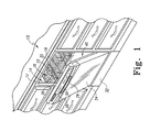
- a dishwashing machine 10 (hereinafter dishwasher 10) is shown.
- the dishwasher 10 has a tub 12 that defines a washing chamber 14 into which a user may place dishes and other cooking and eating wares (e.g., plates, bowls, glasses, flatware, pots, pans, bowls, etc.) to be washed.
- the dishwasher 10 includes a number of racks 16 located in the tub 12.
- An upper dish rack 16 is shown in FIG. 1 , although a lower dish rack is also included in the dishwasher 10.
- a number of roller assemblies 18 are positioned between the dish racks 16 and the tub 12. The roller assemblies 18 allow the dish racks 16 to extend from and retract into the tub 12, which facilitates the loading and unloading of the dish racks 16.
- the roller assemblies 18 include a number of rollers 20 that move along a corresponding support rail 22.
- a door 24 is hinged to the lower front edge of the tub 12.
- the door 24 permits user access to the tub 12 to load and unload the dishwasher 10.
- the door 24 also seals the front of the dishwasher 10 during a wash cycle.
- a control panel 26 is located at the top of the door 24.
- the control panel 26 includes a number of controls 28, such as buttons and knobs, which are used by a controller (not shown) to control the operation of the dishwasher 10.
- a handle 30 is also included in the control panel 26. The user may use the handle 30 to unlatch and open the door 24 to access the tub 12.
- a machine compartment 32 is located below the tub 12.
- the machine compartment 32 is sealed from the tub 12.
- the machine compartment 32 does not fill with fluid and is not exposed to spray during the operation of the dishwasher 10.
- the machine compartment 32 houses a recirculation pump assembly 34 and the drain pump 36, as well as the dishwasher's other motor(s) and valve(s), along with the associated wiring and plumbing.
- the tub 12 of the dishwasher 10 includes a number of side walls 40 extending upwardly from a bottom wall 42 to define the washing chamber 14.
- the open front side 44 of the tub 12 defines an access opening 46 of the dishwasher 10.
- the access opening 46 provides the user with access to the dish racks 16 positioned in the washing chamber 14 when the door 24 is open.
- the door 24 seals the access opening 46, which prevents the user from accessing the dish racks 16.
- the door 24 also prevents fluid from escaping through the access opening 46 of the dishwasher 10 during a wash cycle.
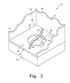
- the bottom wall 42 of the tub 12 has a sump 50 positioned therein.
- fluid enters the tub 12 through a hole 48 defined in the side wall 40.
- the sloped configuration of the bottom wall 42 directs fluid into the sump 50.
- the recirculation pump assembly 34 removes such water and/or wash chemistry from the sump 50 through a hole 52 defined the bottom of the sump 50 after the sump 50 is partially filled with fluid.
- the recirculation pump assembly 34 is fluidly coupled to a rotating spray arm 54 that sprays water and/or wash chemistry onto the dish racks 16 (and hence any wares positioned thereon). Additional rotating spray arms (not shown) are positioned above the spray arm 54. It should also be appreciated that the dishwashing machine 10 may include other spray arms positioned at various locations in the tub 12. As shown in FIG. 2 , the spray arm 54 has a number of nozzles 56. Fluid passes from the recirculation pump assembly 34 into the spray arm 54 and then exits the spray arm 54 through the nozzles 56. In the illustrative embodiment described herein, the nozzles 56 are embodied simply as holes formed in the spray arm 54.
- the nozzles 56 may include inserts such as tips or other similar structures that are placed into the holes formed in the spray arm 54. Such inserts may be useful in configuring the spray direction or spray pattern of the fluid expelled from the spray arm 54.
- the drain pump 36 removes both wash fluid and soil particles from the sump 50 and the tub 12.
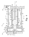
- the recirculation pump assembly 34 includes a wash pump 60 that is secured to a housing 62.
- the housing 62 includes cylindrical filter casing 64 positioned between a manifold 68 and the wash pump 60.
- the manifold 68 has an inlet port 70, which is fluidly coupled to the hole 52 defined in the sump 50, and an outlet port 72, which is fluidly coupled to the drain pump 36.
- Another outlet port 74 extends upwardly from the wash pump 60 and is fluidly coupled to the rotating spray arm 54.
- recirculation pump assembly 34 is included in the dishwasher 10, it will be appreciated that in other embodiments the recirculation pump assembly 34 may be a device separate from the dishwasher 10.
- the recirculation pump assembly 34 might be positioned in a cabinet adjacent to the dishwasher 10. In such embodiments, a number of fluid hoses may be used to connect the recirculation pump assembly 34 to the dishwasher 10.
- the filter casing 64 is a hollow cylinder having a side wall 76 that extends from an end 78 secured to the manifold 68 to an opposite end 80 secured to the wash pump 60.
- the side wall 76 defines a filter chamber 82 that extends the length of the filter casing 64.
- the side wall 76 has an inner surface 84 facing the filter chamber 82.
- a number of rectangular ribs 85 extend from the inner surface 84 into the filter chamber 82.
- the ribs 85 are configured to create drag to counteract the movement of fluid within the filter chamber 82. It should be appreciated that in other embodiments each of the ribs 85 may take the form of a wedge, cylinder, pyramid, or other shape configured to create drag to counteract the movement of fluid within the filter chamber 82.
- the manifold 68 has a main body 86 that is secured to the end 78 of the filter casing 64.
- the inlet port 70 extends upwardly from the main body 86 and is configured to be coupled to a fluid hose (not shown) extending from the hole 52 defined in the sump 50.
- the inlet port 70 opens through a sidewall 87 of the main body 86 into the filter chamber 82 of the filter casing 64.
- a mixture of fluid and soil particles advances from the sump 50 into the filter chamber 82 and fills the filter chamber 82.
- the inlet port 70 has a filter screen 88 positioned at an upper end 90.
- the filter screen 88 has a plurality of holes 91 extending therethrough. Each of the holes 91 is sized such that large soil particles are prevented from advancing into the filter chamber 82.
- a passageway places the outlet port 72 of the manifold 68 in fluid communication with the filter chamber 82.
- the drain pump 36 When the drain pump 36 is energized, fluid and soil particles from the sump 50 pass downwardly through the inlet port 70 into the filter chamber 82. Fluid then advances from the filter chamber 82 through the passageway and out the outlet port 72.
- the wash pump 60 is secured at the opposite end 80 of the filter casing 64.
- the wash pump 60 includes a motor 92 (see FIG. 3 ) secured to a cylindrical pump housing 94.
- the pump housing 94 includes a side wall 96 extending from a base wall 98 to an end wall 100.
- the base wall 98 is secured to the motor 92 while the end wall 100 is secured to the end 80 of the filter casing 64.
- the walls 96, 98, 100 define an impeller chamber 102 that fills with fluid during the wash cycle.
- the outlet port 74 is coupled to the side wall 96 of the pump housing 94 and opens into the chamber 102.
- the outlet port 74 is configured to receive a fluid hose (not shown) such that the outlet port 74 may be fluidly coupled to the spray arm 54.
- the wash pump 60 also includes an impeller 104.
- the impeller 104 has a shell 106 that extends from a back end 108 to a front end 110.
- the back end 108 of the shell 106 is positioned in the chamber 102 and has a bore 112 formed therein.
- a drive shaft 114 which is rotatably coupled to the motor 92, is received in the bore 112.
- the motor 92 acts on the drive shaft 114 to rotate the impeller 104 about an imaginary axis 116 in the direction indicated by arrow 118 (see FIG. 5 ).
- the motor 92 is connected to a power supply (not shown), which provides the electric current necessary for the motor 92 to spin the drive shaft 114 and rotate the impeller 104.
- the motor 92 is configured to rotate the impeller 104 about the axis 116 at 3200 rpm.
- the front end 110 of the impeller shell 106 is positioned in the filter chamber 82 of the filter casing 64 and has an inlet opening 120 formed in the center thereof.
- the shell 106 has a number of vanes 122 that extend away from the inlet opening 120 to an outer edge 124 of the shell 106.
- the rotation of the impeller 104 about the axis 116 draws fluid from the filter chamber 82 of the filter casing 64 into the inlet opening 120.
- the fluid is then forced by the rotation of the impeller 104 outward along the vanes 122. Fluid exiting the impeller 104 is advanced out of the chamber 102 through the outlet port 74 to the spray arm 54.
- the front end 110 of the impeller shell 106 is coupled to a rotary filter 130 positioned in the filter chamber 82 of the filter casing 64.
- the filter 130 has a cylindrical filter drum 132 extending from an end 134 secured to the impeller shell 106 to an end 136 rotatably coupled to a bearing 138, which is secured the main body 86 of the manifold 68. As such, the filter 130 is operable to rotate about the axis 116 with the impeller 104.
- a filter sheet 140 extends from one end 134 to the other end 136 of the filter drum 132 and encloses a hollow interior 142.
- the sheet 140 includes a number of holes 144, and each hole 144 extends from an outer surface 146 of the sheet 140 to an inner surface 148.
- the sheet 140 is a sheet of chemically etched metal.
- Each hole 144 is sized to allow for the passage of wash fluid into the hollow interior 142 and prevent the passage of soil particles.
- the filter sheet 140 divides the filter chamber 82 into two parts. As wash fluid and removed soil particles enter the filter chamber 82 through the inlet port 70, a mixture 150 of fluid and soil particles is collected in the filter chamber 82 in a region 152 external to the filter sheet 140. Because the holes 144 permit fluid to pass into the hollow interior 142, a volume of filtered fluid 156 is formed in the hollow interior 142.
- a flow diverter 160 is positioned in the hollow interior 142 of the filter 130.
- the diverter 160 has a body 166 that is positioned adjacent to the inner surface 148 of the sheet 140.
- the body 166 has an outer surface 168 that defines a circular arc 170 having a radius smaller than the radius of the sheet 140.
- a number of arms 172 extend away from the body 166 and secure the diverter 160 to a beam 174 positioned in the center of the filter 130.
- the beam 174 is coupled at an end 176 to the side wall 87 of the manifold 68. In this way, the beam 174 secures the body 166 to the housing 62.
- Another flow diverter 180 is positioned between the outer surface 146 of the sheet 140 and the inner surface 84 of the housing 62.
- the diverter 180 has a fin-shaped body 182 that extends from a leading edge 184 to a trailing end 186. As shown in FIG. 4 , the body 182 extends along the length of the filter drum 132 from one end 134 to the other end 136. It will be appreciated that in other embodiments the diverter 180 may take other forms, such as, for example, having an inner surface that defines a circular arc having a radius larger than the radius of the sheet 140.
- the body 182 is secured to a beam 184.
- the beam 187 extends from the side wall 87 of the manifold 68. In this way, the beam 187 secures the body 182 to the housing 62.
- the diverter 180 is positioned opposite the diverter 160 on the same side of the filter chamber 82.
- the diverter 160 is spaced apart from the diverter 180 so as to create a gap 188 therebetween.
- the sheet 140 is positioned within the gap 188.
- wash fluid such as water and/or wash chemistry (i.e., water and/or detergents, enzymes, surfactants, and other cleaning or conditioning chemistry), enters the tub 12 through the hole 48 defined in the side wall 40 and flows into the sump 50 and down the hole 52 defined therein.
- wash fluid passes through the holes 144 extending through the filter sheet 140 into the hollow interior 142.
- the dishwasher 10 activates the motor 92.
- Activation of the motor 92 causes the impeller 104 and the filter 130 to rotate.
- the rotation of the impeller 104 draws wash fluid from the filter chamber 82 through the filter sheet 140 and into the inlet opening 120 of the impeller shell 106. Fluid then advances outward along the vanes 122 of the impeller shell 106 and out of the chamber 102 through the outlet port 74 to the spray arm 54.
- wash fluid When wash fluid is delivered to the spray arm 54, it is expelled from the spray arm 54 onto any dishes or other wares positioned in the washing chamber 14. Wash fluid removes soil particles located on the dishwares, and the mixture of wash fluid and soil particles falls onto the bottom wall 42 of the tub 12.
- the sloped configuration of the bottom wall 42 directs that mixture into the sump 50 and down the hole 52 defined in the sump 50.
- the size of the holes 144 prevents the soil particles of the mixture 152 from moving into the hollow interior 142. As a result, those soil particles accumulate on the outer surface 146 of the sheet 140 and cover the holes 144, thereby preventing fluid from passing into the hollow interior 142.
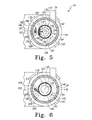
- the rotation of the filter 130 about the axis 116 causes the mixture 150 of fluid and soil particles within the filter chamber 82 to rotate about the axis 116 in the direction indicated by the arrow 118. Centrifugal force urges the soil particles toward the side wall 76 as the mixture 150 rotates about the axis 116.
- the diverters 160, 180 divide the mixture 150 into a first portion 190, which advances through the gap 188, and a second portion 192, which bypasses the gap 188. As the portion 190 advances through the gap 188, the angular velocity of the portion 190 increases relative to its previous velocity as well as relative to the second portion 192. The increase in angular velocity results in a low pressure region between the diverters 160, 180.
- FIG. 6 a cross-section of another embodiment of the rotary filter 130 with a single flow diverter 200.
- the diverter 200 like the diverter 180 of the embodiment of FIGS. 1-5 , is positioned within the filter chamber 82 external of the hollow interior 142.
- the diverter 200 is secured to the side wall 87 of the manifold 68 via a beam 202.
- the diverter 200 has a fin-shaped body 204 that extends from a tip 206 to a trailing end 208.
- the tip 206 has a leading edge 210 that is positioned proximate to the outer surface 146 of the sheet 140, and the tip 206 and the outer surface 146 of the sheet 140 define a gap 212 therebetween.
- the rotation of the filter 130 about the axis 116 causes the mixture 150 of fluid and soil particles to rotate about the axis 116 in the direction indicated by the arrow 118.
- the diverter 200 divides the mixture 150 into a first portion 290, which passes through the gap 212 defined between the diverter 200 and the sheet 140, and a second portion 292, which bypasses the gap 212.
- the angular velocity of the first portion 290 of the mixture 150 increases relative to the second portion 292.
- the increase in angular velocity results in low pressure in the gap 212 between the diverter 200 and the outer surface 146 of the sheet 140.
- the gap 212 is sized such that the angular velocity of the first portion 290 is at least sixteen percent greater than the angular velocity of the second portion 292 of the fluid.
Landscapes
- Structures Of Non-Positive Displacement Pumps (AREA)
- Filtering Of Dispersed Particles In Gases (AREA)
- Washing And Drying Of Tableware (AREA)
Priority Applications (3)
| Application Number | Priority Date | Filing Date | Title |
|---|---|---|---|
| PL10195238T PL2335547T3 (pl) | 2009-12-21 | 2010-12-15 | Obrotowy filtr bębna do zmywarki |
| EP12188007.4A EP2554093A3 (de) | 2009-12-21 | 2010-12-15 | Drehtrommelfilter für einen Geschirrspüler |
| EP12153892.0A EP2449946B1 (de) | 2009-12-21 | 2010-12-15 | Drehtrommelfilter für einen Geschirrspüler |
Applications Claiming Priority (1)
| Application Number | Priority Date | Filing Date | Title |
|---|---|---|---|
| US12/643,394 US8746261B2 (en) | 2009-12-21 | 2009-12-21 | Rotating drum filter for a dishwashing machine |
Related Child Applications (1)
| Application Number | Title | Priority Date | Filing Date |
|---|---|---|---|
| EP12153892.0 Division-Into | 2012-02-03 |
Publications (2)
| Publication Number | Publication Date |
|---|---|
| EP2335547A1 true EP2335547A1 (de) | 2011-06-22 |
| EP2335547B1 EP2335547B1 (de) | 2012-07-04 |
Family
ID=43856253
Family Applications (3)
| Application Number | Title | Priority Date | Filing Date |
|---|---|---|---|
| EP10195238A Active EP2335547B1 (de) | 2009-12-21 | 2010-12-15 | Drehender Filter für einen Geschirrspüler |
| EP12188007.4A Withdrawn EP2554093A3 (de) | 2009-12-21 | 2010-12-15 | Drehtrommelfilter für einen Geschirrspüler |
| EP12153892.0A Active EP2449946B1 (de) | 2009-12-21 | 2010-12-15 | Drehtrommelfilter für einen Geschirrspüler |
Family Applications After (2)
| Application Number | Title | Priority Date | Filing Date |
|---|---|---|---|
| EP12188007.4A Withdrawn EP2554093A3 (de) | 2009-12-21 | 2010-12-15 | Drehtrommelfilter für einen Geschirrspüler |
| EP12153892.0A Active EP2449946B1 (de) | 2009-12-21 | 2010-12-15 | Drehtrommelfilter für einen Geschirrspüler |
Country Status (4)
| Country | Link |
|---|---|
| US (1) | US8746261B2 (de) |
| EP (3) | EP2335547B1 (de) |
| BR (1) | BRPI1006083A2 (de) |
| PL (1) | PL2335547T3 (de) |
Cited By (15)
| Publication number | Priority date | Publication date | Assignee | Title |
|---|---|---|---|---|
| US8667974B2 (en) | 2009-12-21 | 2014-03-11 | Whirlpool Corporation | Rotating filter for a dishwashing machine |
| US9237836B2 (en) | 2012-05-30 | 2016-01-19 | Whirlpool Corporation | Rotating filter for a dishwasher |
| US9364131B2 (en) | 2010-12-13 | 2016-06-14 | Whirlpool Corporation | Rotating filter for a dishwashing machine |
| US9451862B2 (en) | 2012-06-01 | 2016-09-27 | Whirlpool Corporation | Dishwasher with unitary wash module |
| US9532700B2 (en) | 2012-06-01 | 2017-01-03 | Whirlpool Corporation | Dishwasher with overflow conduit |
| US9532697B2 (en) | 2010-12-03 | 2017-01-03 | Whirlpool Corporation | Dishwasher with unitary wash module |
| US9538898B2 (en) | 2011-05-16 | 2017-01-10 | Whirlpool Corporation | Dishwasher with filter assembly |
| US9668636B2 (en) | 2010-11-16 | 2017-06-06 | Whirlpool Corporation | Method and apparatus for dishwasher with common heating element for multiple treating chambers |
| US9833120B2 (en) | 2012-06-01 | 2017-12-05 | Whirlpool Corporation | Heating air for drying dishes in a dishwasher using an in-line wash liquid heater |
| US9861251B2 (en) | 2011-06-20 | 2018-01-09 | Whirlpool Corporation | Filter with artificial boundary for a dishwashing machine |
| US9918609B2 (en) | 2009-12-21 | 2018-03-20 | Whirlpool Corporation | Rotating drum filter for a dishwashing machine |
| US10058228B2 (en) | 2012-02-27 | 2018-08-28 | Whirlpool Corporation | Soil chopping system for a dishwasher |
| US10058227B2 (en) | 2011-06-20 | 2018-08-28 | Whirlpool Corporation | Filter assembly for a dishwasher |
| US10070769B2 (en) | 2011-06-20 | 2018-09-11 | Whirlpool Corporation | Rotating filter for a dishwashing machine |
| US10653291B2 (en) | 2011-06-20 | 2020-05-19 | Whirlpool Corporation | Ultra micron filter for a dishwasher |
Families Citing this family (14)
| Publication number | Priority date | Publication date | Assignee | Title |
|---|---|---|---|---|
| US9687135B2 (en) | 2009-12-21 | 2017-06-27 | Whirlpool Corporation | Automatic dishwasher with pump assembly |
| US8746261B2 (en) | 2009-12-21 | 2014-06-10 | Whirlpool Corporation | Rotating drum filter for a dishwashing machine |
| US9113766B2 (en) | 2010-11-16 | 2015-08-25 | Whirlpool Corporation | Method and apparatus for dishwasher with common heating element for multiple treating chambers |
| US9034112B2 (en) | 2010-12-03 | 2015-05-19 | Whirlpool Corporation | Dishwasher with shared heater |
| US20120138106A1 (en) * | 2010-12-03 | 2012-06-07 | Whirlpool Corporation | Dishwasher with single valve to fill multiple compartments |
| US9107559B2 (en) | 2011-05-16 | 2015-08-18 | Whirlpool Corporation | Dishwasher with filter assembly |
| US9010344B2 (en) | 2011-06-20 | 2015-04-21 | Whirlpool Corporation | Rotating filter for a dishwashing machine |
| US9693672B2 (en) | 2011-09-22 | 2017-07-04 | Whirlpool Corporation | Dishwasher with sprayer |
| US9730570B2 (en) | 2012-05-30 | 2017-08-15 | Whirlpool Corporation | Reduced sound with a rotating filter for a dishwasher |
| US9554688B2 (en) | 2012-10-23 | 2017-01-31 | Whirlpool Corporation | Rotating filter for a dishwasher and methods of cleaning a rotating filter |
| US9532701B2 (en) | 2013-03-01 | 2017-01-03 | Whirlpool Corporation | Dishwasher with sprayer |
| US9713413B2 (en) | 2013-07-01 | 2017-07-25 | Whirlpool Corporation | Dishwasher for treating dishes |
| US9532699B2 (en) | 2013-07-15 | 2017-01-03 | Whirlpool Corporation | Dishwasher with sprayer |
| DE102017116759A1 (de) | 2016-09-12 | 2018-03-15 | Whirlpool Corporation (A Delaware Corporation) | Ultrafeiner mikron-filter für einen geschirrspüler |
Citations (7)
| Publication number | Priority date | Publication date | Assignee | Title |
|---|---|---|---|---|
| DE1134489B (de) * | 1958-10-22 | 1962-08-09 | Boelkow Entwicklungen Kg | Sieb- und Filtereinrichtung fuer mit Fluessigkeit arbeitende Reinigungsmaschine |
| DE4433842C1 (de) * | 1994-09-22 | 1996-03-21 | Bauknecht Hausgeraete | Vorrichtung zum Spülen in einer Geschirrspülmaschine |
| EP0752231A1 (de) * | 1995-07-06 | 1997-01-08 | Merloni Elettrodomestici S.p.A. | Geschirrspülmaschine mit Filtereinrichtung und -verfahren |
| DE19652235A1 (de) * | 1996-12-16 | 1998-06-25 | Whirlpool Co | Geschirrspülmaschine mit unterem Sprüharm und Umwälzpumpe für das Spülwasser |
| EP1256308A2 (de) * | 2001-05-08 | 2002-11-13 | Electrolux Home Products Corporation N.V. | Geschirrspülmaschine mit Abfallzerkleinerungsvorrichtung |
| US20100154841A1 (en) * | 2008-12-22 | 2010-06-24 | Whirlpool Corporation | Dishwasher with soil removal |
| US20100224223A1 (en) * | 2009-03-05 | 2010-09-09 | Whirlpool Corporation | Dishwasher with a drive motor for filter or spray arm |
Family Cites Families (187)
| Publication number | Priority date | Publication date | Assignee | Title |
|---|---|---|---|---|
| US2734122A (en) | 1956-02-07 | Dishwashers | ||
| US1617021A (en) | 1921-10-08 | 1927-02-08 | Robert B Mitchell | Dishwashing machine |
| CH169630A (de) | 1933-04-18 | 1934-06-15 | Baumgaertel Otto | Vorrichtung im Spülwasser-Kreislaufsystem von Geschirrwaschmaschinen zum Reinigen des umlaufenden Spülwassers. |
| US2154559A (en) | 1933-10-23 | 1939-04-18 | Bolinders Fabriks Ab | Dishwashing machine |
| US2422022A (en) | 1942-01-15 | 1947-06-10 | Hotpoint Inc | Dishwashing and drying apparatus |
| US3026628A (en) | 1956-08-07 | 1962-03-27 | Whirlpool Co | Drying system for dishwashers |
| US3068877A (en) | 1958-09-12 | 1962-12-18 | Gen Motors Corp | Dishwasher |
| NL259913A (de) | 1960-01-13 | |||
| US3103227A (en) | 1961-04-18 | 1963-09-10 | Westinghouse Electric Corp | Dishwasher apparatus |
| US3186417A (en) | 1962-11-27 | 1965-06-01 | Waste King Corp | Dishwasher heating system with dual electrical heating means |
| DE1453070B2 (de) | 1962-11-30 | 1970-09-10 | Siemens-Electrogeräte GmbH, 1000 Berlin u. 8000 München | Geschirrspülmaschine für Tafel- und Küchengeschirr |
| BE638824A (de) | 1963-10-08 | |||
| US3288154A (en) | 1964-11-02 | 1966-11-29 | Gen Motors Corp | Plural compartment dishwasher with unitary pump |
| DE1428358A1 (de) | 1964-12-16 | 1968-11-14 | Braun Ag | Geschirrspuelmaschine mit im Kreislauf gefuehrtem Spuelwasser |
| GB1123789A (en) | 1966-06-20 | 1968-08-14 | Colston Ltd C | Improvements in dishwashing and other washing machines |
| US3542594A (en) | 1968-06-19 | 1970-11-24 | Maytag Co | Fluid control system |
| US3575185A (en) | 1968-10-23 | 1971-04-20 | Gen Motors Corp | Self-cleaning dishwasher strainer |
| US3586011A (en) | 1969-08-04 | 1971-06-22 | Zanussi A Spa Industrie | Dish washer |
| US3801280A (en) | 1971-11-11 | 1974-04-02 | Upjohn Co | Solubility-dissolution test apparatus and method |
| US3846321A (en) | 1973-05-30 | 1974-11-05 | Mine Safety Appliances Co | Centrifugal filtering apparatus |
| US3989054A (en) | 1975-10-28 | 1976-11-02 | General Motors Corporation | Dishwasher system |
| DE2610379C3 (de) | 1976-03-12 | 1984-02-09 | Bosch-Siemens Hausgeräte GmbH, 7000 Stuttgart | Geschirrspülmaschine |
| DE7636915U1 (de) | 1976-11-24 | 1977-08-18 | Bosch-Siemens Hausgeraete Gmbh, 7000 Stuttgart | Rueckschlagventil fuer wasserfuehrende geraete, insbesondere geschirrspuel- oder waschmaschinen |
| IT1077167B (it) | 1977-05-13 | 1985-05-04 | Montedison Spa | Lavastoviglie costitutito da un insieme di blocchi funzionali in materiale termoplastico realizzati separatamente per stampaggio |
| IT1083311B (it) | 1977-06-16 | 1985-05-21 | Zanussi A Spa Industrie | Perfezionamenti nei dispositivi di controllo del livello del liquido nell vasca di una macchina lavatrice |
| US4180095A (en) | 1977-11-21 | 1979-12-25 | White Consolidated Industries, Inc. | Dishwasher float switch control assembly |
| US4326552A (en) | 1979-01-23 | 1982-04-27 | Ingo Bleckmann | Heater for heating flows of fluid and dishwashing machine provided therewith |
| DE8026931U1 (de) | 1980-10-08 | 1982-02-04 | Bosch-Siemens Hausgeräte GmbH, 7000 Stuttgart | Einrichtung zum erwaermen von spuelfluessigkeit und luft in einer geschirrspuelmaschine |
| DE3038080C2 (de) | 1980-10-08 | 1983-09-22 | Bosch-Siemens Hausgeräte GmbH, 7000 Stuttgart | Geschirrspülmaschine mit einem Gebläse zum Fördern von Frischluft |
| FR2508304B1 (fr) | 1981-06-30 | 1986-02-07 | Esswein Sa | Lave-vaisselle a filtre de recyclage automatiquement nettoye |
| DE3337369A1 (de) | 1983-10-14 | 1985-04-25 | Jakobus Janhsen | Geschirrspuelmaschine |
| FR2569973B1 (fr) | 1984-09-11 | 1987-06-12 | Esswein Sa | Lave-vaisselle a microfiltrage de liquide |
| IT1183898B (it) | 1985-06-21 | 1987-10-22 | Eltek Spa | Macchina lavatrice quale lavastoviglie dotata di motore elettrico unico monodirezionale per le funzioni di lavaggio e scarico dell'acqua |
| DE8519840U1 (de) | 1985-07-09 | 1985-08-22 | Elpag Ag Chur, Chur | Elektrischer Durchlauferhitzer |
| IT1197983B (it) | 1986-11-13 | 1988-12-21 | Candy Elettrodomestici | Ciclo di lavaggio per macchine lavatrici, in particolare lavastoviglie e macchina lavatrice operante secondo tale ciclo |
| IT215240Z2 (it) | 1988-11-22 | 1990-09-11 | Dall Oglio Erminio | Macchina lavastoviglie perfezionata. |
| US5002890A (en) | 1988-11-29 | 1991-03-26 | The United States Of America As Represented By The Administrator Of The National Aeronautics And Space Administration | Spiral vane bioreactor |
| DE3842997C2 (de) | 1988-12-21 | 1994-09-01 | Licentia Gmbh | Geschirrspülmaschine |
| EP0383028A3 (de) | 1989-02-14 | 1992-05-06 | Licentia Patent-Verwaltungs-GmbH | Geschirrspülmaschine mit einer elektromechanischen Umsteuervorrichtung |
| IT216714Z2 (it) | 1989-06-27 | 1991-09-19 | Cabassa Di E Dall Oglio & C S | Macchina lavastoviglie perfezionata. |
| DE4011834A1 (de) | 1990-04-12 | 1991-10-17 | Donat Johannes | Wechsel-geschirrspueler mit zwei kammern und zentralem spuelsystem |
| SE500246C2 (sv) | 1990-04-26 | 1994-05-24 | Electrolux Ab | Anornding vid en diskmaskin |
| DE4016915A1 (de) | 1990-05-25 | 1991-11-28 | Nordenskjoeld Reinhart Von | Verfahren und vorrichtung zur mechanischen abscheidung von feststoffen aus einem fluid |
| FR2667798B1 (fr) | 1990-10-15 | 1993-06-11 | Aerospatiale | Filtre collecteur d'aerosols autochauffant pour pyrolyse. |
| EP0521815B2 (de) | 1991-07-02 | 1998-03-18 | Miele & Cie. GmbH & Co. | Geschirrspülmaschine mit einer den Spülraum mit der Umgebungsluft verbindenden Entlüftungsöffnung oder dergl. |
| DE4124742C2 (de) | 1991-07-25 | 1994-06-09 | Eloma Gmbh | Gargerät, insbesondere für stückiges Gargut |
| DE4131914C2 (de) * | 1991-09-25 | 1997-09-18 | Aeg Hausgeraete Gmbh | Siebkombination für Haushalt-Geschirrspülmaschinen |
| DE69233635T2 (de) | 1991-12-20 | 2007-07-05 | Fisher & Paykel Appliances Ltd., East Tamaki | Geschirrspülmaschine |
| KR940009563B1 (ko) | 1992-09-04 | 1994-10-15 | 대우전자주식회사 | 식기 세척기 |
| IT1264057B (it) | 1993-02-09 | 1996-09-09 | Mario Chioffi | Dispositivo per l'evacuazione controllata del vapore acqueo dalla camera di lavaggio di una macchina lavastoviglie. |
| DK29093D0 (da) | 1993-03-15 | 1993-03-15 | Per Stobbe | Heated silicon carbide filter |
| DE4413432C1 (de) | 1994-04-18 | 1995-08-31 | Bauknecht Hausgeraete | Programmgesteuerte Geschirrspülmaschine |
| DE4418523A1 (de) | 1994-05-27 | 1995-11-30 | Licentia Gmbh | Haushalt-Geschirrspülmaschine mit schwimmergesteuerter Siebkombination |
| DE9415486U1 (de) | 1994-09-24 | 1994-11-17 | Bauknecht Hausgeräte GmbH, 70563 Stuttgart | Geschirrspülmaschine mit einem Spülwasser-Kreislauf und einer Filtervorrichtung mit Reinigungsvorrichtung |
| DE9416710U1 (de) | 1994-10-18 | 1994-12-01 | Röser, Karlo, 74074 Heilbronn | Vorrichtung zum Reinigen von Geschirr |
| US5569383A (en) | 1994-12-15 | 1996-10-29 | Delaware Capital Formation, Inc. | Filter with axially and rotatably movable wiper |
| US5454298A (en) | 1995-01-31 | 1995-10-03 | Lu; Tsai-Chuan | Apparatus for meshing dehydrating and desiccating food products |
| DE19503589A1 (de) | 1995-02-03 | 1996-08-08 | Bosch Siemens Hausgeraete | Wasserzuführungs-Einrichtung für ein wasserführendes Haushaltgerät |
| US5618424A (en) | 1995-04-21 | 1997-04-08 | Nagaoka International Corp. | Rotary drum type device for separating solid particles from a liquid |
| IT1276718B1 (it) | 1995-06-14 | 1997-11-03 | Smeg Spa | Dispositivo per controllare il lavaggio del filtro di una macchina lavastoviglie |
| US5924432A (en) | 1995-10-17 | 1999-07-20 | Whirlpool Corporation | Dishwasher having a wash liquid recirculation system |
| DE19546965A1 (de) | 1995-12-15 | 1997-06-19 | Bosch Siemens Hausgeraete | Wasserführendes, programmgesteuertes Haushaltgerät |
| US5868937A (en) | 1996-02-13 | 1999-02-09 | Mainstream Engineering Corporation | Process and system for recycling and reusing gray water |
| TW422082U (en) | 1996-07-26 | 2001-02-11 | Sharp Kk | Dish washer for washing dishes by rotating a dish basket, and the dish basket therefor |
| IT1289179B1 (it) | 1997-01-20 | 1998-09-29 | Elettrobar S R L | Valvola di ritenuta per fluidi |
| IT1289186B1 (it) | 1997-01-22 | 1998-09-29 | Smeg Spa | Dispositivo di filtrazione perfezionato per macchine lavastoviglie |
| FR2764065B1 (fr) | 1997-05-30 | 1999-07-16 | Schlumberger Services Petrol | Procede et dispositif pour la caracterisation d'effluents de forages petroliers |
| DE19736794C2 (de) | 1997-08-23 | 2000-04-06 | Whirlpool Co | Geschirrspülmaschine mit unterem und oberem Sprüharm und einer Umwälzpumpe |
| US6460555B1 (en) | 1998-09-21 | 2002-10-08 | Maytag Corporation | Dual dishwasher construction |
| US6491049B1 (en) | 1998-09-21 | 2002-12-10 | Maytag Corporation | Lid construction for drawer dishwasher |
| JP2000107114A (ja) | 1998-10-09 | 2000-04-18 | Matsushita Electric Ind Co Ltd | 食器洗浄機 |
| DE19857103A1 (de) | 1998-12-10 | 2000-06-15 | Bsh Bosch Siemens Hausgeraete | Haushalt-Geschirrspülmaschine |
| IT1306971B1 (it) | 1999-01-11 | 2001-10-11 | Elbi Int Spa | Distributore idraulico. |
| FR2790013B1 (fr) | 1999-02-18 | 2001-05-25 | Siebe Appliance Controls Sa | Distributeur d'eau pour machine a laver |
| DE19951838A1 (de) | 1999-10-28 | 2001-05-10 | Aeg Hausgeraete Gmbh | Geschirrspülmaschine mit einem Spülbehälter |
| US6289908B1 (en) | 1999-12-01 | 2001-09-18 | Marjorie K. Kelsey | Double dishwasher |
| JP2001190479A (ja) | 2000-01-13 | 2001-07-17 | Osaka Gas Co Ltd | 食器洗浄機 |
| JP3985408B2 (ja) | 2000-01-17 | 2007-10-03 | 松下電器産業株式会社 | 食器洗い乾燥機 |
| US7270132B2 (en) | 2000-02-14 | 2007-09-18 | Matsushita Electric Industrial Co., Ltd. | Washer |
| ITPN20000011A1 (it) | 2000-02-15 | 2001-08-15 | Electrolux Zanussi Elettrodome | Lavastoviglie perfezionata dotata di un'unita' funzionale elettro-idraulica |
| ITPN20000037A1 (it) | 2000-06-07 | 2001-12-07 | Electrolux Zanussi Elettrodome | Lavastoviglie ergonomica |
| DE10065571B4 (de) | 2000-12-28 | 2012-04-19 | BSH Bosch und Siemens Hausgeräte GmbH | Geschirrspülmaschine |
| ITMI20010029U1 (it) | 2001-01-18 | 2002-07-18 | Candy Spa | Apparato di riscaldamento per macchina lavastoviglie |
| US7000437B2 (en) | 2001-01-18 | 2006-02-21 | Shell Oil Company | System and method for economically viable and environmentally friendly central processing of home laundry |
| DE10106514A1 (de) | 2001-02-13 | 2002-08-29 | Miele & Cie | Trocknungsgebläse für eine Geschirrspülmaschine |
| DE60102828T2 (de) | 2001-12-06 | 2005-04-28 | Candy S.P.A., Monza | Haushaltsgeschirrspülmaschine mit einer Tür, die ein eine Vertiefung aufweisenden Paneel aufweist, sowie einen Geschirrspülmitteldosierbehälter, der vom oberen Geschirrkorb gestützt ist |
| DE20122635U1 (de) | 2001-12-21 | 2006-10-05 | BSH Bosch und Siemens Hausgeräte GmbH | Umsteuereinrichtung, insbesondere für eine Geschirrspülmaschine |
| US7069181B2 (en) | 2001-12-21 | 2006-06-27 | BSH Bosch und Siemens Hausgeräte | Method of determining the energy and water consumption of dishwashers, and dishwashers |
| DE10209975A1 (de) | 2002-03-07 | 2003-09-25 | Bsh Bosch Siemens Hausgeraete | Elektrisch beheizbare Waschmaschine |
| US7406843B2 (en) | 2002-05-08 | 2008-08-05 | Whirlpool Corporation | Remote sump with film heater and auto purge |
| JP2003336909A (ja) | 2002-05-15 | 2003-11-28 | Yozo Oko | 静止型集光装置 |
| JP3829759B2 (ja) | 2002-05-23 | 2006-10-04 | 松下電器産業株式会社 | 食器洗い機 |
| KR100441019B1 (ko) | 2002-07-09 | 2004-07-21 | 삼성전자주식회사 | 식기세척기 |
| DE60206490T2 (de) | 2002-07-31 | 2006-05-18 | Candy S.P.A., Monza | Geschirrspülmaschine mit durch den Spülwasserstrom rotierbarer Filter- und Zerkleinerungsvorrichtung |
| CN2571812Y (zh) | 2002-08-01 | 2003-09-10 | 杭州松下家用电器有限公司 | 一种双桶洗衣机用进水切换机构 |
| DE10239495A1 (de) | 2002-08-28 | 2004-03-11 | BSH Bosch und Siemens Hausgeräte GmbH | Siebvorrichtung |
| US7232494B2 (en) | 2002-09-06 | 2007-06-19 | Whirlpool Corporation | Stop start wash cycle for dishwashers |
| CN1235539C (zh) | 2002-11-01 | 2006-01-11 | 三星电子株式会社 | 洗碗机控制方法 |
| KR100457589B1 (ko) | 2002-11-28 | 2004-11-17 | 엘지전자 주식회사 | 식기세척기의 유로개폐장치 |
| ATE410113T1 (de) | 2002-12-31 | 2008-10-15 | Arcelik As | Geschirrspülmaschine |
| JP3956870B2 (ja) | 2003-03-10 | 2007-08-08 | 松下電器産業株式会社 | 食器洗い機 |
| US7445013B2 (en) | 2003-06-17 | 2008-11-04 | Whirlpool Corporation | Multiple wash zone dishwasher |
| US7523758B2 (en) | 2003-06-17 | 2009-04-28 | Whirlpool Corporation | Dishwasher having rotating zone wash sprayer |
| DE60302143T2 (de) | 2003-07-16 | 2006-08-03 | Bonferraro S.P.A. | Geschirrspülmaschine mit Mitteln zur Reduzierung des Energie- und Wasserverbrauchs |
| KR100488033B1 (ko) | 2003-07-31 | 2005-05-06 | 엘지전자 주식회사 | 식기 세척기의 세척 유로 제어 장치 |
| DE10346675A1 (de) | 2003-10-08 | 2005-05-04 | Bsh Bosch Siemens Hausgeraete | Geschirrspüler mit Zerkleinerungsvorrichtung |
| JP2005124979A (ja) | 2003-10-27 | 2005-05-19 | Hitachi Home & Life Solutions Inc | 食器洗い機 |
| US7198054B2 (en) | 2003-12-17 | 2007-04-03 | Maytag Corporation | Dishwasher having a side-by-side rack system |
| DE10359617A1 (de) | 2003-12-18 | 2005-07-28 | BSH Bosch und Siemens Hausgeräte GmbH | Vorrichtung und Verfahren zum Filtern von Partikeln aus einer Flüssigkeit in einer Geschirrspülmaschine |
| DE102004003536A1 (de) | 2004-01-23 | 2005-08-11 | BSH Bosch und Siemens Hausgeräte GmbH | Flüssigkeitsführendes elektrisches Haushaltsgerät |
| WO2005115216A1 (en) | 2004-05-25 | 2005-12-08 | Arcelik Anonim Sirketi | A washing machine with a flood-preventing mechanism |
| US7497222B2 (en) | 2004-07-02 | 2009-03-03 | Bsh Bosch Und Siemens Hausgeraete | Comminution device and method for comminuting residue in a dishwasher |
| US7350527B2 (en) | 2004-07-06 | 2008-04-01 | Whirlpool Corporation | Dishwasher filter system |
| DE102004060950A1 (de) * | 2004-12-17 | 2006-06-29 | BSH Bosch und Siemens Hausgeräte GmbH | Geschirrspülmaschine mit wartungsarmem Siebsystem |
| CN2761660Y (zh) | 2005-01-10 | 2006-03-01 | 叶鹏 | 双洗全自动洗衣机 |
| US8241434B2 (en) | 2005-01-25 | 2012-08-14 | Johnson Electric S.A. | Dishwasher with high voltage DC motor |
| US8551255B2 (en) | 2005-02-09 | 2013-10-08 | Whirlpool Corporation | Rapid heat system for a multi-tub dishwasher |
| PL2332457T3 (pl) | 2005-05-10 | 2013-05-31 | Electrolux Home Products Corp Nv | Zmywarka |
| DE102005023428A1 (de) | 2005-05-20 | 2006-11-23 | Premark Feg L.L.C. (N.D.Ges.D. Staates Delaware), Wilmington | Gewerbliche Geschirrspülmaschine |
| KR101208280B1 (ko) | 2005-07-11 | 2012-12-05 | 엘지전자 주식회사 | 식기세척기 및 그 제어방법 |
| DE502005005404D1 (de) | 2005-07-14 | 2008-10-30 | Meiko Maschinenbau Gmbh & Co | Prozesswasseraufbereitung in Mehrtankreinigungsautomaten |
| CN2873093Y (zh) | 2005-08-10 | 2007-02-28 | Bsh博施及西门子家用器具有限公司 | 洗碗机、特别是家用洗碗机 |
| DE102005038433A1 (de) | 2005-08-12 | 2007-02-15 | Premark Feg L.L.C. (N.D.Ges.D. Staates Delaware), Wilmington | Transport-Geschirrspülmaschine |
| DE102005039385A1 (de) | 2005-08-20 | 2007-02-22 | Premark Feg L.L.C., Wilmington | Transport-Geschirrspülmaschine |
| JP2007068601A (ja) | 2005-09-05 | 2007-03-22 | Matsushita Electric Ind Co Ltd | 食器洗い機 |
| CN1966129A (zh) | 2005-11-15 | 2007-05-23 | 张民良 | 过滤、换热和热压榨等功能的柔韧管式固液处理机 |
| US7363093B2 (en) | 2005-11-29 | 2008-04-22 | Whirlpool Corporation | Control system for a multi-compartment dishwasher |
| JP4483773B2 (ja) | 2005-12-01 | 2010-06-16 | パナソニック株式会社 | 食器洗い乾燥機 |
| DE102005062480B4 (de) | 2005-12-27 | 2014-05-22 | BSH Bosch und Siemens Hausgeräte GmbH | Geschirrspülmaschine |
| DE102006023389A1 (de) | 2006-05-17 | 2007-11-22 | Herbert Kannegiesser Gmbh | Verfahren und Vorrichtung zum Behandeln, vorzugsweise Waschen, Schleudern und/oder Trocknen, von Wäsche |
| CN2907830Y (zh) | 2006-05-25 | 2007-06-06 | 宝山钢铁股份有限公司 | 自动清洁滤网过滤器 |
| EP1980193A1 (de) | 2006-05-30 | 2008-10-15 | Electrolux Home Products Corporation N.V. | Verfahren zur Reinigung des Filters eines Geschirrspülers und Geschirrspüler zur Ausführung dieses Verfahrens |
| EP1882436A1 (de) | 2006-07-25 | 2008-01-30 | Electrolux Home Products Corporation N.V. | Geschirrspülmaschine mit einem ein Umschaltventil aufweisenden Hydraulikkreis |
| JP2008093196A (ja) | 2006-10-12 | 2008-04-24 | Matsushita Electric Ind Co Ltd | 食器洗い機 |
| EP1929924A1 (de) | 2006-12-06 | 2008-06-11 | Electrolux Home Products Corporation N.V. | Geschirrspüler |
| DE102007007133A1 (de) | 2007-02-13 | 2008-08-14 | Meiko Maschinenbau Gmbh & Co. Kg | Frontlader-Geschirrspülmaschine mit Wärmerückgewinnung |
| JP4238919B2 (ja) | 2007-04-05 | 2009-03-18 | パナソニック株式会社 | 食器洗い乾燥機 |
| JP5018201B2 (ja) | 2007-04-16 | 2012-09-05 | パナソニック株式会社 | 食器洗い乾燥機 |
| JP2008264724A (ja) | 2007-04-24 | 2008-11-06 | Chugoku Electric Power Co Inc:The | ストレーナ装置 |
| US20080289664A1 (en) | 2007-05-24 | 2008-11-27 | Rockwell Anthony L | Modular drip pan and component mounting assembly for a dishwasher |
| PL2022385T3 (pl) | 2007-08-08 | 2011-10-31 | Electrolux Home Products Corp Nv | Zmywarka |
| TW200916042A (en) | 2007-10-11 | 2009-04-16 | Panasonic Corp | Dish washing/drying machine |
| DE102007056425B4 (de) | 2007-11-23 | 2016-03-10 | BSH Hausgeräte GmbH | Wasserführendes Haushaltsgerät mit einer Sicherheitseinrichtung |
| DE102007060193A1 (de) | 2007-12-14 | 2009-06-25 | BSH Bosch und Siemens Hausgeräte GmbH | Wasserführendes Haushaltsgerät |
| DE102007060196A1 (de) | 2007-12-14 | 2009-06-18 | BSH Bosch und Siemens Hausgeräte GmbH | Geschirrspülmaschine |
| DE102007060197B4 (de) | 2007-12-14 | 2016-07-07 | BSH Hausgeräte GmbH | Wasserführendes Haushaltsgerät |
| DE102007060195A1 (de) | 2007-12-14 | 2009-06-18 | BSH Bosch und Siemens Hausgeräte GmbH | Wasserführendes Haushaltsgerät |
| DE102007061038B4 (de) | 2007-12-18 | 2016-10-27 | BSH Hausgeräte GmbH | Wasserführendes Haushaltsgerät |
| DE102007061036B4 (de) | 2007-12-18 | 2022-09-15 | BSH Hausgeräte GmbH | Wasserführendes Haushaltsgerät mit einem selbstreinigenden Filtersystem |
| US7896977B2 (en) | 2007-12-19 | 2011-03-01 | Whirlpool Corporation | Dishwasher with sequencing corner nozzles |
| ITTO20070939A1 (it) | 2007-12-24 | 2009-06-25 | Elbi Int Spa | Dispositivo riscaldatore di fluidi per una macchina lavatrice, in particolare una macchina lavastoviglie |
| DE102008016171A1 (de) | 2008-03-28 | 2009-10-01 | BSH Bosch und Siemens Hausgeräte GmbH | Wasserführendes Haushaltsgerät |
| EP2127587A1 (de) | 2008-05-31 | 2009-12-02 | Electrolux Home Products Corporation N.V. | Wasserauslaufsystem für eine Geschirrspülmaschine |
| EP2138087A1 (de) | 2008-06-27 | 2009-12-30 | Electrolux Home Products Corporation N.V. | Geschirrspüler und Verfahren zum Einlassen von Wasser in einen Geschirrspüler |
| US8424546B2 (en) | 2008-07-15 | 2013-04-23 | Electrolux Home Products, Inc. | Sump assembly for a dishwasher, and associated method |
| JP2010035745A (ja) | 2008-08-04 | 2010-02-18 | Toshiba Corp | 洗濯機 |
| CN201276653Y (zh) | 2008-08-19 | 2009-07-22 | 合肥荣事达洗衣设备制造有限公司 | 双桶洗衣机进水转换阀 |
| US8282741B2 (en) | 2008-08-19 | 2012-10-09 | Whirlpool Corporation | Sequencing spray arm assembly for a dishwasher |
| KR101520680B1 (ko) | 2008-08-21 | 2015-05-21 | 엘지전자 주식회사 | 식기 세척기 |
| KR101526987B1 (ko) | 2008-08-21 | 2015-06-11 | 엘지전자 주식회사 | 식기 세척기 및 그 제어방법 |
| KR101016311B1 (ko) | 2008-10-01 | 2011-02-22 | 엘지전자 주식회사 | 식기 세척기 |
| US7909936B2 (en) | 2008-12-19 | 2011-03-22 | Whirlpool Corporation | Dishwasher final steam rinse method |
| CN201361486Y (zh) | 2009-01-08 | 2009-12-16 | 刘琪 | 水源热泵系统专用滤水器 |
| JP2010187796A (ja) | 2009-02-17 | 2010-09-02 | Panasonic Corp | 食器洗い機 |
| CN201410325Y (zh) | 2009-06-09 | 2010-02-24 | 青岛威特水煤浆技术开发有限公司 | 动力式过滤器 |
| CN201473770U (zh) | 2009-06-12 | 2010-05-19 | 冉伊虹 | 双腔洗衣机 |
| DE102009027910A1 (de) | 2009-07-22 | 2011-01-27 | BSH Bosch und Siemens Hausgeräte GmbH | Geschirrspülmaschine mit einem optimierten Siebsystem |
| DE102009028278A1 (de) | 2009-08-06 | 2011-02-10 | BSH Bosch und Siemens Hausgeräte GmbH | Wasserführendes Haushaltsgerät |
| CN101654855B (zh) | 2009-09-09 | 2012-01-04 | 温清武 | 一种多桶式洗衣机 |
| US8776808B2 (en) | 2009-09-17 | 2014-07-15 | Whirlpool Corporation | Rotary drum filter for a dishwashing machine |
| KR101633932B1 (ko) | 2009-11-25 | 2016-06-27 | 엘지전자 주식회사 | 식기 세척기 |
| US8667974B2 (en) | 2009-12-21 | 2014-03-11 | Whirlpool Corporation | Rotating filter for a dishwashing machine |
| US9918609B2 (en) | 2009-12-21 | 2018-03-20 | Whirlpool Corporation | Rotating drum filter for a dishwashing machine |
| DE102010061215A1 (de) | 2009-12-21 | 2011-06-22 | Whirlpool Corp. (a Delaware Corp.), Mich. | Geschirrspüler mit einheitlichem Spülmodul |
| US8746261B2 (en) | 2009-12-21 | 2014-06-10 | Whirlpool Corporation | Rotating drum filter for a dishwashing machine |
| US8834648B2 (en) | 2010-10-21 | 2014-09-16 | Whirlpool Corporation | Dishwasher with controlled rotation of lower spray arm |
| US20120118336A1 (en) | 2010-11-16 | 2012-05-17 | Whirlpool Corporation | Dishwasher with filter cleaning assembly |
| US9113766B2 (en) | 2010-11-16 | 2015-08-25 | Whirlpool Corporation | Method and apparatus for dishwasher with common heating element for multiple treating chambers |
| US9034112B2 (en) | 2010-12-03 | 2015-05-19 | Whirlpool Corporation | Dishwasher with shared heater |
| US20120138106A1 (en) | 2010-12-03 | 2012-06-07 | Whirlpool Corporation | Dishwasher with single valve to fill multiple compartments |
| US20120138107A1 (en) | 2010-12-03 | 2012-06-07 | Whirlpool Corporation | Dishwasher with single pump and filter unit for multiple compartments |
| US9107559B2 (en) | 2011-05-16 | 2015-08-18 | Whirlpool Corporation | Dishwasher with filter assembly |
| US8733376B2 (en) | 2011-05-16 | 2014-05-27 | Whirlpool Corporation | Dishwasher with filter assembly |
| US20120318296A1 (en) | 2011-06-20 | 2012-12-20 | Whirlpool Corporation | Ultra micron filter for a dishwasher |
| US9005369B2 (en) | 2011-06-20 | 2015-04-14 | Whirlpool Corporation | Filter assembly for a dishwasher |
| US9265401B2 (en) | 2011-06-20 | 2016-02-23 | Whirlpool Corporation | Rotating filter for a dishwashing machine |
| US9010344B2 (en) | 2011-06-20 | 2015-04-21 | Whirlpool Corporation | Rotating filter for a dishwashing machine |
-
2009
- 2009-12-21 US US12/643,394 patent/US8746261B2/en active Active
-
2010
- 2010-12-15 EP EP10195238A patent/EP2335547B1/de active Active
- 2010-12-15 PL PL10195238T patent/PL2335547T3/pl unknown
- 2010-12-15 EP EP12188007.4A patent/EP2554093A3/de not_active Withdrawn
- 2010-12-15 EP EP12153892.0A patent/EP2449946B1/de active Active
- 2010-12-20 BR BRPI1006083-9A patent/BRPI1006083A2/pt not_active IP Right Cessation
Patent Citations (7)
| Publication number | Priority date | Publication date | Assignee | Title |
|---|---|---|---|---|
| DE1134489B (de) * | 1958-10-22 | 1962-08-09 | Boelkow Entwicklungen Kg | Sieb- und Filtereinrichtung fuer mit Fluessigkeit arbeitende Reinigungsmaschine |
| DE4433842C1 (de) * | 1994-09-22 | 1996-03-21 | Bauknecht Hausgeraete | Vorrichtung zum Spülen in einer Geschirrspülmaschine |
| EP0752231A1 (de) * | 1995-07-06 | 1997-01-08 | Merloni Elettrodomestici S.p.A. | Geschirrspülmaschine mit Filtereinrichtung und -verfahren |
| DE19652235A1 (de) * | 1996-12-16 | 1998-06-25 | Whirlpool Co | Geschirrspülmaschine mit unterem Sprüharm und Umwälzpumpe für das Spülwasser |
| EP1256308A2 (de) * | 2001-05-08 | 2002-11-13 | Electrolux Home Products Corporation N.V. | Geschirrspülmaschine mit Abfallzerkleinerungsvorrichtung |
| US20100154841A1 (en) * | 2008-12-22 | 2010-06-24 | Whirlpool Corporation | Dishwasher with soil removal |
| US20100224223A1 (en) * | 2009-03-05 | 2010-09-09 | Whirlpool Corporation | Dishwasher with a drive motor for filter or spray arm |
Cited By (22)
| Publication number | Priority date | Publication date | Assignee | Title |
|---|---|---|---|---|
| US8667974B2 (en) | 2009-12-21 | 2014-03-11 | Whirlpool Corporation | Rotating filter for a dishwashing machine |
| US10779703B2 (en) | 2009-12-21 | 2020-09-22 | Whirlpool Corporation | Rotating drum filter for a dishwashing machine |
| US9918609B2 (en) | 2009-12-21 | 2018-03-20 | Whirlpool Corporation | Rotating drum filter for a dishwashing machine |
| US9668636B2 (en) | 2010-11-16 | 2017-06-06 | Whirlpool Corporation | Method and apparatus for dishwasher with common heating element for multiple treating chambers |
| US9532697B2 (en) | 2010-12-03 | 2017-01-03 | Whirlpool Corporation | Dishwasher with unitary wash module |
| US9364131B2 (en) | 2010-12-13 | 2016-06-14 | Whirlpool Corporation | Rotating filter for a dishwashing machine |
| US11882977B2 (en) | 2011-05-16 | 2024-01-30 | Whirlpool Corporation | Dishwasher with filter assembly |
| US9538898B2 (en) | 2011-05-16 | 2017-01-10 | Whirlpool Corporation | Dishwasher with filter assembly |
| US9700196B2 (en) | 2011-05-16 | 2017-07-11 | Whirlpool Corporation | Dishwasher with filter assembly |
| US9861251B2 (en) | 2011-06-20 | 2018-01-09 | Whirlpool Corporation | Filter with artificial boundary for a dishwashing machine |
| US10058227B2 (en) | 2011-06-20 | 2018-08-28 | Whirlpool Corporation | Filter assembly for a dishwasher |
| US10070769B2 (en) | 2011-06-20 | 2018-09-11 | Whirlpool Corporation | Rotating filter for a dishwashing machine |
| US10178939B2 (en) | 2011-06-20 | 2019-01-15 | Whirlpool Corporation | Filter with artificial boundary for a dishwashing machine |
| US10314457B2 (en) | 2011-06-20 | 2019-06-11 | Whirlpool Corporation | Filter with artificial boundary for a dishwashing machine |
| US10653291B2 (en) | 2011-06-20 | 2020-05-19 | Whirlpool Corporation | Ultra micron filter for a dishwasher |
| US10813525B2 (en) | 2011-06-20 | 2020-10-27 | Whirlpool Corporation | Ultra micron filter for a dishwasher |
| US10058228B2 (en) | 2012-02-27 | 2018-08-28 | Whirlpool Corporation | Soil chopping system for a dishwasher |
| US10076226B2 (en) | 2012-05-30 | 2018-09-18 | Whirlpool Corporation | Rotating filter for a dishwasher |
| US9237836B2 (en) | 2012-05-30 | 2016-01-19 | Whirlpool Corporation | Rotating filter for a dishwasher |
| US9833120B2 (en) | 2012-06-01 | 2017-12-05 | Whirlpool Corporation | Heating air for drying dishes in a dishwasher using an in-line wash liquid heater |
| US9532700B2 (en) | 2012-06-01 | 2017-01-03 | Whirlpool Corporation | Dishwasher with overflow conduit |
| US9451862B2 (en) | 2012-06-01 | 2016-09-27 | Whirlpool Corporation | Dishwasher with unitary wash module |
Also Published As
| Publication number | Publication date |
|---|---|
| EP2449946A1 (de) | 2012-05-09 |
| EP2554093A3 (de) | 2013-09-04 |
| PL2335547T3 (pl) | 2012-12-31 |
| US8746261B2 (en) | 2014-06-10 |
| EP2449946B1 (de) | 2013-10-09 |
| BRPI1006083A2 (pt) | 2012-08-07 |
| EP2554093A2 (de) | 2013-02-06 |
| EP2335547B1 (de) | 2012-07-04 |
| US20110146730A1 (en) | 2011-06-23 |
Similar Documents
| Publication | Publication Date | Title |
|---|---|---|
| EP2335547B1 (de) | Drehender Filter für einen Geschirrspüler | |
| US10779703B2 (en) | Rotating drum filter for a dishwashing machine | |
| US9010344B2 (en) | Rotating filter for a dishwashing machine | |
| US8667974B2 (en) | Rotating filter for a dishwashing machine | |
| US10070769B2 (en) | Rotating filter for a dishwashing machine | |
| EP2462857B1 (de) | Geschirrspüler mit einem rotierenden Filter | |
| US9282874B2 (en) | Rotary drum filter for a dishwashing machine | |
| EP1819263B8 (de) | Geschirrspülerbodenwanne | |
| US10314457B2 (en) | Filter with artificial boundary for a dishwashing machine | |
| US20150265129A1 (en) | Automatic dishwasher with pump assembly | |
| US20240081605A1 (en) | Filter cleaning assembly for a dishwasher appliance |
Legal Events
| Date | Code | Title | Description |
|---|---|---|---|
| PUAI | Public reference made under article 153(3) epc to a published international application that has entered the european phase |
Free format text: ORIGINAL CODE: 0009012 |
|
| AK | Designated contracting states |
Kind code of ref document: A1 Designated state(s): AL AT BE BG CH CY CZ DE DK EE ES FI FR GB GR HR HU IE IS IT LI LT LU LV MC MK MT NL NO PL PT RO RS SE SI SK SM TR |
|
| AX | Request for extension of the european patent |
Extension state: BA ME |
|
| 17P | Request for examination filed |
Effective date: 20111122 |
|
| GRAP | Despatch of communication of intention to grant a patent |
Free format text: ORIGINAL CODE: EPIDOSNIGR1 |
|
| RIC1 | Information provided on ipc code assigned before grant |
Ipc: A47L 15/42 20060101AFI20120112BHEP |
|
| GRAS | Grant fee paid |
Free format text: ORIGINAL CODE: EPIDOSNIGR3 |
|
| GRAA | (expected) grant |
Free format text: ORIGINAL CODE: 0009210 |
|
| AK | Designated contracting states |
Kind code of ref document: B1 Designated state(s): AL AT BE BG CH CY CZ DE DK EE ES FI FR GB GR HR HU IE IS IT LI LT LU LV MC MK MT NL NO PL PT RO RS SE SI SK SM TR |
|
| REG | Reference to a national code |
Ref country code: GB Ref legal event code: FG4D |
|
| REG | Reference to a national code |
Ref country code: CH Ref legal event code: EP |
|
| REG | Reference to a national code |
Ref country code: AT Ref legal event code: REF Ref document number: 564797 Country of ref document: AT Kind code of ref document: T Effective date: 20120715 |
|
| REG | Reference to a national code |
Ref country code: IE Ref legal event code: FG4D |
|
| REG | Reference to a national code |
Ref country code: DE Ref legal event code: R096 Ref document number: 602010002102 Country of ref document: DE Effective date: 20120830 |
|
| REG | Reference to a national code |
Ref country code: AT Ref legal event code: MK05 Ref document number: 564797 Country of ref document: AT Kind code of ref document: T Effective date: 20120704 |
|
| REG | Reference to a national code |
Ref country code: NL Ref legal event code: VDEP Effective date: 20120704 |
|
| PG25 | Lapsed in a contracting state [announced via postgrant information from national office to epo] |
Ref country code: SI Free format text: LAPSE BECAUSE OF FAILURE TO SUBMIT A TRANSLATION OF THE DESCRIPTION OR TO PAY THE FEE WITHIN THE PRESCRIBED TIME-LIMIT Effective date: 20120704 |
|
| REG | Reference to a national code |
Ref country code: LT Ref legal event code: MG4D Effective date: 20120704 |
|
| REG | Reference to a national code |
Ref country code: PL Ref legal event code: T3 |
|
| PG25 | Lapsed in a contracting state [announced via postgrant information from national office to epo] |
Ref country code: IS Free format text: LAPSE BECAUSE OF FAILURE TO SUBMIT A TRANSLATION OF THE DESCRIPTION OR TO PAY THE FEE WITHIN THE PRESCRIBED TIME-LIMIT Effective date: 20121104 Ref country code: AT Free format text: LAPSE BECAUSE OF FAILURE TO SUBMIT A TRANSLATION OF THE DESCRIPTION OR TO PAY THE FEE WITHIN THE PRESCRIBED TIME-LIMIT Effective date: 20120704 Ref country code: BE Free format text: LAPSE BECAUSE OF FAILURE TO SUBMIT A TRANSLATION OF THE DESCRIPTION OR TO PAY THE FEE WITHIN THE PRESCRIBED TIME-LIMIT Effective date: 20120704 Ref country code: CY Free format text: LAPSE BECAUSE OF FAILURE TO SUBMIT A TRANSLATION OF THE DESCRIPTION OR TO PAY THE FEE WITHIN THE PRESCRIBED TIME-LIMIT Effective date: 20120704 Ref country code: HR Free format text: LAPSE BECAUSE OF FAILURE TO SUBMIT A TRANSLATION OF THE DESCRIPTION OR TO PAY THE FEE WITHIN THE PRESCRIBED TIME-LIMIT Effective date: 20120704 Ref country code: NO Free format text: LAPSE BECAUSE OF FAILURE TO SUBMIT A TRANSLATION OF THE DESCRIPTION OR TO PAY THE FEE WITHIN THE PRESCRIBED TIME-LIMIT Effective date: 20121004 Ref country code: FI Free format text: LAPSE BECAUSE OF FAILURE TO SUBMIT A TRANSLATION OF THE DESCRIPTION OR TO PAY THE FEE WITHIN THE PRESCRIBED TIME-LIMIT Effective date: 20120704 Ref country code: LT Free format text: LAPSE BECAUSE OF FAILURE TO SUBMIT A TRANSLATION OF THE DESCRIPTION OR TO PAY THE FEE WITHIN THE PRESCRIBED TIME-LIMIT Effective date: 20120704 |
|
| PG25 | Lapsed in a contracting state [announced via postgrant information from national office to epo] |
Ref country code: PT Free format text: LAPSE BECAUSE OF FAILURE TO SUBMIT A TRANSLATION OF THE DESCRIPTION OR TO PAY THE FEE WITHIN THE PRESCRIBED TIME-LIMIT Effective date: 20121105 Ref country code: LV Free format text: LAPSE BECAUSE OF FAILURE TO SUBMIT A TRANSLATION OF THE DESCRIPTION OR TO PAY THE FEE WITHIN THE PRESCRIBED TIME-LIMIT Effective date: 20120704 Ref country code: SE Free format text: LAPSE BECAUSE OF FAILURE TO SUBMIT A TRANSLATION OF THE DESCRIPTION OR TO PAY THE FEE WITHIN THE PRESCRIBED TIME-LIMIT Effective date: 20120704 Ref country code: GR Free format text: LAPSE BECAUSE OF FAILURE TO SUBMIT A TRANSLATION OF THE DESCRIPTION OR TO PAY THE FEE WITHIN THE PRESCRIBED TIME-LIMIT Effective date: 20121005 |
|
| PG25 | Lapsed in a contracting state [announced via postgrant information from national office to epo] |
Ref country code: NL Free format text: LAPSE BECAUSE OF FAILURE TO SUBMIT A TRANSLATION OF THE DESCRIPTION OR TO PAY THE FEE WITHIN THE PRESCRIBED TIME-LIMIT Effective date: 20120704 |
|
| PG25 | Lapsed in a contracting state [announced via postgrant information from national office to epo] |
Ref country code: RO Free format text: LAPSE BECAUSE OF FAILURE TO SUBMIT A TRANSLATION OF THE DESCRIPTION OR TO PAY THE FEE WITHIN THE PRESCRIBED TIME-LIMIT Effective date: 20120704 Ref country code: EE Free format text: LAPSE BECAUSE OF FAILURE TO SUBMIT A TRANSLATION OF THE DESCRIPTION OR TO PAY THE FEE WITHIN THE PRESCRIBED TIME-LIMIT Effective date: 20120704 Ref country code: ES Free format text: LAPSE BECAUSE OF FAILURE TO SUBMIT A TRANSLATION OF THE DESCRIPTION OR TO PAY THE FEE WITHIN THE PRESCRIBED TIME-LIMIT Effective date: 20121015 Ref country code: CZ Free format text: LAPSE BECAUSE OF FAILURE TO SUBMIT A TRANSLATION OF THE DESCRIPTION OR TO PAY THE FEE WITHIN THE PRESCRIBED TIME-LIMIT Effective date: 20120704 Ref country code: DK Free format text: LAPSE BECAUSE OF FAILURE TO SUBMIT A TRANSLATION OF THE DESCRIPTION OR TO PAY THE FEE WITHIN THE PRESCRIBED TIME-LIMIT Effective date: 20120704 |
|
| PLBE | No opposition filed within time limit |
Free format text: ORIGINAL CODE: 0009261 |
|
| STAA | Information on the status of an ep patent application or granted ep patent |
Free format text: STATUS: NO OPPOSITION FILED WITHIN TIME LIMIT |
|
| PG25 | Lapsed in a contracting state [announced via postgrant information from national office to epo] |
Ref country code: SK Free format text: LAPSE BECAUSE OF FAILURE TO SUBMIT A TRANSLATION OF THE DESCRIPTION OR TO PAY THE FEE WITHIN THE PRESCRIBED TIME-LIMIT Effective date: 20120704 |
|
| 26N | No opposition filed |
Effective date: 20130405 |
|
| PG25 | Lapsed in a contracting state [announced via postgrant information from national office to epo] |
Ref country code: RS Free format text: LAPSE BECAUSE OF FAILURE TO SUBMIT A TRANSLATION OF THE DESCRIPTION OR TO PAY THE FEE WITHIN THE PRESCRIBED TIME-LIMIT Effective date: 20120704 Ref country code: BG Free format text: LAPSE BECAUSE OF FAILURE TO SUBMIT A TRANSLATION OF THE DESCRIPTION OR TO PAY THE FEE WITHIN THE PRESCRIBED TIME-LIMIT Effective date: 20121004 Ref country code: MC Free format text: LAPSE BECAUSE OF NON-PAYMENT OF DUE FEES Effective date: 20121231 |
|
| REG | Reference to a national code |
Ref country code: DE Ref legal event code: R097 Ref document number: 602010002102 Country of ref document: DE Effective date: 20130405 |
|
| REG | Reference to a national code |
Ref country code: IE Ref legal event code: MM4A |
|
| PG25 | Lapsed in a contracting state [announced via postgrant information from national office to epo] |
Ref country code: IE Free format text: LAPSE BECAUSE OF NON-PAYMENT OF DUE FEES Effective date: 20121215 |
|
| PG25 | Lapsed in a contracting state [announced via postgrant information from national office to epo] |
Ref country code: AL Free format text: LAPSE BECAUSE OF FAILURE TO SUBMIT A TRANSLATION OF THE DESCRIPTION OR TO PAY THE FEE WITHIN THE PRESCRIBED TIME-LIMIT Effective date: 20120704 Ref country code: MT Free format text: LAPSE BECAUSE OF FAILURE TO SUBMIT A TRANSLATION OF THE DESCRIPTION OR TO PAY THE FEE WITHIN THE PRESCRIBED TIME-LIMIT Effective date: 20120704 |
|
| PG25 | Lapsed in a contracting state [announced via postgrant information from national office to epo] |
Ref country code: TR Free format text: LAPSE BECAUSE OF FAILURE TO SUBMIT A TRANSLATION OF THE DESCRIPTION OR TO PAY THE FEE WITHIN THE PRESCRIBED TIME-LIMIT Effective date: 20120704 |
|
| PG25 | Lapsed in a contracting state [announced via postgrant information from national office to epo] |
Ref country code: SM Free format text: LAPSE BECAUSE OF FAILURE TO SUBMIT A TRANSLATION OF THE DESCRIPTION OR TO PAY THE FEE WITHIN THE PRESCRIBED TIME-LIMIT Effective date: 20120704 Ref country code: LU Free format text: LAPSE BECAUSE OF NON-PAYMENT OF DUE FEES Effective date: 20121215 |
|
| PG25 | Lapsed in a contracting state [announced via postgrant information from national office to epo] |
Ref country code: HU Free format text: LAPSE BECAUSE OF FAILURE TO SUBMIT A TRANSLATION OF THE DESCRIPTION OR TO PAY THE FEE WITHIN THE PRESCRIBED TIME-LIMIT Effective date: 20101215 |
|
| PG25 | Lapsed in a contracting state [announced via postgrant information from national office to epo] |
Ref country code: MK Free format text: LAPSE BECAUSE OF FAILURE TO SUBMIT A TRANSLATION OF THE DESCRIPTION OR TO PAY THE FEE WITHIN THE PRESCRIBED TIME-LIMIT Effective date: 20120704 |
|
| REG | Reference to a national code |
Ref country code: CH Ref legal event code: PL |
|
| PG25 | Lapsed in a contracting state [announced via postgrant information from national office to epo] |
Ref country code: CH Free format text: LAPSE BECAUSE OF NON-PAYMENT OF DUE FEES Effective date: 20141231 Ref country code: LI Free format text: LAPSE BECAUSE OF NON-PAYMENT OF DUE FEES Effective date: 20141231 |
|
| REG | Reference to a national code |
Ref country code: FR Ref legal event code: PLFP Year of fee payment: 6 |
|
| REG | Reference to a national code |
Ref country code: FR Ref legal event code: PLFP Year of fee payment: 7 |
|
| REG | Reference to a national code |
Ref country code: FR Ref legal event code: PLFP Year of fee payment: 8 |
|
| PGFP | Annual fee paid to national office [announced via postgrant information from national office to epo] |
Ref country code: PL Payment date: 20171002 Year of fee payment: 8 |
|
| PG25 | Lapsed in a contracting state [announced via postgrant information from national office to epo] |
Ref country code: PL Free format text: LAPSE BECAUSE OF NON-PAYMENT OF DUE FEES Effective date: 20181215 |
|
| P01 | Opt-out of the competence of the unified patent court (upc) registered |
Effective date: 20230522 |
|
| REG | Reference to a national code |
Ref country code: DE Ref legal event code: R082 Ref document number: 602010002102 Country of ref document: DE Representative=s name: SEIDE, CHRISTIAN, DIPL.-PHYS.(ETH ZUERICH) DR., DE |
|
| PGFP | Annual fee paid to national office [announced via postgrant information from national office to epo] |
Ref country code: GB Payment date: 20231219 Year of fee payment: 14 |
|
| PGFP | Annual fee paid to national office [announced via postgrant information from national office to epo] |
Ref country code: IT Payment date: 20231221 Year of fee payment: 14 Ref country code: FR Payment date: 20231226 Year of fee payment: 14 |
|
| PGFP | Annual fee paid to national office [announced via postgrant information from national office to epo] |
Ref country code: DE Payment date: 20231227 Year of fee payment: 14 |