EP2204302A1 - Système d'affichage - Google Patents
Système d'affichage Download PDFInfo
- Publication number
- EP2204302A1 EP2204302A1 EP10158773A EP10158773A EP2204302A1 EP 2204302 A1 EP2204302 A1 EP 2204302A1 EP 10158773 A EP10158773 A EP 10158773A EP 10158773 A EP10158773 A EP 10158773A EP 2204302 A1 EP2204302 A1 EP 2204302A1
- Authority
- EP
- European Patent Office
- Prior art keywords
- data
- display
- image
- information
- transport
- Prior art date
- Legal status (The legal status is an assumption and is not a legal conclusion. Google has not performed a legal analysis and makes no representation as to the accuracy of the status listed.)
- Withdrawn
Links
- 238000000034 method Methods 0.000 claims description 40
- 230000005540 biological transmission Effects 0.000 claims description 35
- 230000008569 process Effects 0.000 claims description 34
- 238000012545 processing Methods 0.000 claims description 32
- 239000000203 mixture Substances 0.000 claims description 29
- 239000000446 fuel Substances 0.000 claims description 16
- 230000006870 function Effects 0.000 claims description 8
- 230000008859 change Effects 0.000 claims description 7
- 230000004397 blinking Effects 0.000 claims 1
- 239000004973 liquid crystal related substance Substances 0.000 description 46
- 238000013461 design Methods 0.000 description 39
- 238000001444 catalytic combustion detection Methods 0.000 description 29
- 230000006872 improvement Effects 0.000 description 16
- 238000010586 diagram Methods 0.000 description 8
- 238000004891 communication Methods 0.000 description 6
- 230000004044 response Effects 0.000 description 5
- 230000010365 information processing Effects 0.000 description 4
- 239000000872 buffer Substances 0.000 description 3
- 238000003745 diagnosis Methods 0.000 description 3
- 230000007257 malfunction Effects 0.000 description 3
- 238000004519 manufacturing process Methods 0.000 description 2
- 230000008054 signal transmission Effects 0.000 description 2
- 230000007704 transition Effects 0.000 description 2
- 208000013586 Complex regional pain syndrome type 1 Diseases 0.000 description 1
- 230000009471 action Effects 0.000 description 1
- 238000006243 chemical reaction Methods 0.000 description 1
- 238000012790 confirmation Methods 0.000 description 1
- 238000001514 detection method Methods 0.000 description 1
- 238000012986 modification Methods 0.000 description 1
- 230000004048 modification Effects 0.000 description 1
- 206010051747 multiple endocrine neoplasia Diseases 0.000 description 1
- 230000002093 peripheral effect Effects 0.000 description 1
- 230000009467 reduction Effects 0.000 description 1
- 238000004088 simulation Methods 0.000 description 1
- 238000012360 testing method Methods 0.000 description 1
- 230000000007 visual effect Effects 0.000 description 1
- 239000002699 waste material Substances 0.000 description 1
Images


Classifications
-
- B—PERFORMING OPERATIONS; TRANSPORTING
- B60—VEHICLES IN GENERAL
- B60K—ARRANGEMENT OR MOUNTING OF PROPULSION UNITS OR OF TRANSMISSIONS IN VEHICLES; ARRANGEMENT OR MOUNTING OF PLURAL DIVERSE PRIME-MOVERS IN VEHICLES; AUXILIARY DRIVES FOR VEHICLES; INSTRUMENTATION OR DASHBOARDS FOR VEHICLES; ARRANGEMENTS IN CONNECTION WITH COOLING, AIR INTAKE, GAS EXHAUST OR FUEL SUPPLY OF PROPULSION UNITS IN VEHICLES
- B60K35/00—Arrangement of adaptations of instruments
-
- B60K35/10—
-
- B60K35/213—
-
- B60K35/60—
-
- G—PHYSICS
- G06—COMPUTING; CALCULATING OR COUNTING
- G06F—ELECTRIC DIGITAL DATA PROCESSING
- G06F3/00—Input arrangements for transferring data to be processed into a form capable of being handled by the computer; Output arrangements for transferring data from processing unit to output unit, e.g. interface arrangements
- G06F3/14—Digital output to display device ; Cooperation and interconnection of the display device with other functional units
-
- G—PHYSICS
- G09—EDUCATION; CRYPTOGRAPHY; DISPLAY; ADVERTISING; SEALS
- G09G—ARRANGEMENTS OR CIRCUITS FOR CONTROL OF INDICATING DEVICES USING STATIC MEANS TO PRESENT VARIABLE INFORMATION
- G09G5/00—Control arrangements or circuits for visual indicators common to cathode-ray tube indicators and other visual indicators
- G09G5/003—Details of a display terminal, the details relating to the control arrangement of the display terminal and to the interfaces thereto
-
- G—PHYSICS
- G09—EDUCATION; CRYPTOGRAPHY; DISPLAY; ADVERTISING; SEALS
- G09G—ARRANGEMENTS OR CIRCUITS FOR CONTROL OF INDICATING DEVICES USING STATIC MEANS TO PRESENT VARIABLE INFORMATION
- G09G5/00—Control arrangements or circuits for visual indicators common to cathode-ray tube indicators and other visual indicators
- G09G5/02—Control arrangements or circuits for visual indicators common to cathode-ray tube indicators and other visual indicators characterised by the way in which colour is displayed
- G09G5/022—Control arrangements or circuits for visual indicators common to cathode-ray tube indicators and other visual indicators characterised by the way in which colour is displayed using memory planes
-
- G—PHYSICS
- G09—EDUCATION; CRYPTOGRAPHY; DISPLAY; ADVERTISING; SEALS
- G09G—ARRANGEMENTS OR CIRCUITS FOR CONTROL OF INDICATING DEVICES USING STATIC MEANS TO PRESENT VARIABLE INFORMATION
- G09G5/00—Control arrangements or circuits for visual indicators common to cathode-ray tube indicators and other visual indicators
- G09G5/14—Display of multiple viewports
-
- B60K2360/11—
-
- G—PHYSICS
- G09—EDUCATION; CRYPTOGRAPHY; DISPLAY; ADVERTISING; SEALS
- G09G—ARRANGEMENTS OR CIRCUITS FOR CONTROL OF INDICATING DEVICES USING STATIC MEANS TO PRESENT VARIABLE INFORMATION
- G09G2340/00—Aspects of display data processing
- G09G2340/10—Mixing of images, i.e. displayed pixel being the result of an operation, e.g. adding, on the corresponding input pixels
-
- G—PHYSICS
- G09—EDUCATION; CRYPTOGRAPHY; DISPLAY; ADVERTISING; SEALS
- G09G—ARRANGEMENTS OR CIRCUITS FOR CONTROL OF INDICATING DEVICES USING STATIC MEANS TO PRESENT VARIABLE INFORMATION
- G09G2340/00—Aspects of display data processing
- G09G2340/12—Overlay of images, i.e. displayed pixel being the result of switching between the corresponding input pixels
- G09G2340/125—Overlay of images, i.e. displayed pixel being the result of switching between the corresponding input pixels wherein one of the images is motion video
-
- G—PHYSICS
- G09—EDUCATION; CRYPTOGRAPHY; DISPLAY; ADVERTISING; SEALS
- G09G—ARRANGEMENTS OR CIRCUITS FOR CONTROL OF INDICATING DEVICES USING STATIC MEANS TO PRESENT VARIABLE INFORMATION
- G09G2360/00—Aspects of the architecture of display systems
- G09G2360/02—Graphics controller able to handle multiple formats, e.g. input or output formats
-
- G—PHYSICS
- G09—EDUCATION; CRYPTOGRAPHY; DISPLAY; ADVERTISING; SEALS
- G09G—ARRANGEMENTS OR CIRCUITS FOR CONTROL OF INDICATING DEVICES USING STATIC MEANS TO PRESENT VARIABLE INFORMATION
- G09G2380/00—Specific applications
- G09G2380/10—Automotive applications
Definitions
- the present invention relates to a display system mounted on a controllable movable body such as a vehicle (for example a display system for an instrument panel).
- a controllable movable body such as a vehicle (for example a display system for an instrument panel).
- information (image data) regarding the image display is typically generated by a single CPU in a centralized manner and displayed on a display. That is to say, the CPU receives sets of information (data) detected or generated by sensors and a system, generates image data based on the supplied data and the data (for image generation) stored in a storage medium or the like, and displays, on a display, images based on the generated data.
- a publicly-known document 1 Japanese Laid-Open Patent Application No. 2002-154393; published on May 28, 2002 discloses, as shown in Fig. 20 , an instrument panel which is provided with an entertainment display 2002a for displaying a navigation image or the like and an information display 2003 for displaying an information service image and an alert image in accordance with a detected running state and running environment of the vehicle.
- the entertainment display 2002a and the information display 2003a are controlled by a CPU 2020.
- the CPU 2020 displays a current location on the entertainment display 2002a (navigation image) based on current location information supplied from a GPS sensor 2027 and map information stored in a ROM 2051.
- the CPU 2020 also displays on the information display 2003a the running state of the vehicle, which is detected by signals supplied from a vehicle speed sensor 2026 and a steering angle sensor 2025.
- an in-vehicle wide display 1010 disclosed by a publicly-known document 2 is, via an image processing device 1012 including VRAM and the like, connected to an information processing device 1016 including a CPU executing a predetermined computation process, a ROM storing a processing program, and an I/O interface.
- This information processing device 1016 receives sets of information from a navigation system 1022, a traffic information communication system 1024, a monitor system 1026, a sensor system 1028, and a diagnosis system 1030. Based on these sets of information, the information processing device 1016 judges the running state and obtains necessary information, and then displays various information items on the wide display 101 by means of the image processing device 1012.
- the CPU 1020 According to the conventional art disclosed in the publicly-known document 1, the CPU 1020 generates the image data for a navigation image displayed on the entertainment display 1002a and also generates the data of a vehicle information image displayed on the information display 1003a. Similarly, according to the publicly-known document 2, the CPU in the information processing device 1016 generates the image data for a navigation image displayed on the wide display 1010 and the image data of a vehicle information image based on the sensor system 1028 or the diagnosis system 1030.
- the present invention was done to solve the above-identified problem, and the objective of the present invention is to improve the stability of image display of a display system mounted on a controllable movable body, so as to increase the safety of the movable body.
- the display system of the present invention which is mounted on a controllable movable body and simultaneously displays, on a display device, images respectively corresponding to plural sets of information including information regarding the movable body, is characterized in that sets of data for displaying the respective images are generated by plural processors, in a shared manner.
- controllable movable body examples include vehicles such as cars and trains, airplanes, and ships.
- Each of such movable bodies has a display system which displays plural sets of information (e.g. various types of information regarding the movable body and various types of amenity information) as images.
- the data for displaying the sets of information as images is generated in a shared manner by plural processors. Therefore, as compared to the conventional art in which processes are contrarily dealt with by a signal processor, the burden on each processor is reduced. As a result, even if an amount of information to be displayed is increased, data for displaying the information as images is stably generated. Moreover, even if one processor malfunctions, another processor can carry on the information display. This makes it possible to improve the stability of image display by the display system, and hence the safety of the movable body is increased.
- the display system of the present invention is preferably arranged such that processors are provided to correspond to the respective sets of information, and the processors generate data for displaying the corresponding sets of information as images.
- the processors corresponding to the respective sets of information are provided, it is possible to use a processor having a suitable function or capability for each set of information. This improves the display stability and reduces the manufacturing costs.
- the display system of the present invention preferably include display control means for generating, from the data generated by the processors, images to be displayed.
- the display means integrates the sets of data generated by the processors and carries out image display.
- each of the processors is not required to associate the data generated by the same with data generated by another processor, and hence the burden on each of the processors is further reduced. It is therefore possible to further improve the stability of the image display.
- the display system of the present invention is preferably arranged such that the data for displaying the images includes image data and image layout data.
- the display control means is provided with a standard image interface for receiving image data from the processors, so that an option is easily added and customization can be easily done.
- the display system of the present invention which is mounted on a controllable movable body and simultaneously displays, on a display device, images respectively corresponding to plural sets of information including information regarding the movable body, may be characterized by including processors which correspond to the respective sets of information and generates image data and image layout data for displaying the images; display control means for generating display data from the image data and the image layout data, the display control means being connected to the display device the processors; a transmission path which transmits the image data between the display control means and the processors; and another transmission path which is different from said transmission path and transmits the image layout data.
- the display system of the present invention which is mounted on a controllable movable body and simultaneously displays, on a display device, images respectively corresponding to plural sets of information including information regarding the movable body, may be characterized by including: processors which correspond to the respective sets of information and generate image data for displaying the images; display control means for generating display data from the image data, the display control means being connected to the display device and the processors; an image layout table which is provided in the display control means and generates image layout data from the information regarding the movable body; and a transmission path which connects the display control means with the processors and transmits the image data, the display means generating the image layout data from the information regarding the movable body and with reference to the image layout table, and generating the display data by laying out the image data with reference to the image layout data.
- the display control means since the display control means has an image layout table, the processors are not required to generate image layout data. This makes it possible to reduce the burden on the processors. If the image layout data is changeable, an addition of an option and customization can be easily done by only changing the image layout data. Also in this case, it is preferable that the information regarding the movable body and image data are transmitted on different transmission paths.
- the display system of the present invention is preferably arranged such that data for displaying an image corresponding to highly important information is generated by a processor which is different from a processor by which data for displaying an image corresponding to other types of information is generated.
- the highly important information is, for example, information regarding the state of the movable body.
- a processor dealing with important information does not deal with other types of information (i.e. less-important information), and hence the burden on the processor dealing with important information is reduced.
- the display system of the present invention is preferably arranged such that data for displaying an image corresponding to information which places a heavy processing load is generated by a processor which is different from a processor by which data for displaying an image corresponding to other types of data is generated.
- a processor dealing with information which places a heavy processing load does not deal with other types of information (i.e. less-important information), and hence the burden on the processor dealing with information which places a heavy processing load is reduced. It is also possible to adopt, for information which places a heavy processing load, a processor with high security or high performance. This further improves the stability of image display.
- the in-vehicle display system of the present invention which displays, as images, plural sets of information including vehicle information, is characterized in that data for displaying the images are generated in a shared manner by plural processors.
- the in-vehicle display system is preferably arranged such that the information includes vehicle information and multimedia information, and data for displaying an image corresponding to the vehicle information is generated by a processor different from a processor by which data for displaying an image corresponding to the multimedia information is generated.
- the in-vehicle display system preferably includes: amenity information and safety information as the multimedia information; a vehicle system processor dealing with the vehicle information; an amenity system processor dealing with amenity information; and a safety system processor dealing with the safety information, and the in-vehicle display system is preferably arranged so that the vehicle system processor generates image data and image layout data which correspond to the vehicle information, the amenity system processor generates image data and image layout data which correspond to the amenity information, whereas the safety system processor generates image data and image layout data which correspond to the safety information.
- the in-vehicle display system preferably includes a graphic controller which carries out image display using the data generated by the processors.
- the in-vehicle display system is preferably arranged such that the graphic controller includes an image layout table, and images indicating the respective sets of information are listed with reference to the image data, image layout data, and the image layout table.
- the in-vehicle display system is preferably arranged such that the image data and the image layout data are transmitted to the graphic controller via different transmission paths.
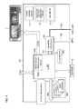
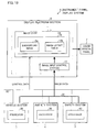
- Fig. 1 is a block diagram of an instrument panel control system for a vehicle on which an instrument panel display system is mounted.
- the instrument panel control system includes: an instrument panel display system 1 of the present invention; an amenity input/output system (amenity system 4) for DVD, TV, GPS, audio or the like; a safety input/output system (safety system 5) for various types of CCDs and sensors; and an in-vehicle LAN 21 for vehicle data transmission.
- the in-vehicle LAN 21 for vehicle data includes a power train in-vehicle LAN 21x and a body in-vehicle LAN 21y.
- the power train in-vehicle LAN 21x is connected to members such as an electric control unit (ECU) 28a for controlling engine-related matters and an electric control unit (ECU) 28b for controlling gear-related matters.
- the body in-vehicle LAN 21y is connected to members such as an electric control unit (ECU) 29a for controlling door-related matters, an electric control unit (ECU) 29b for controlling light-related matters, and an electric control unit (ECU) 29c for controlling air-conditioner-related matters.
- the instrument panel display system (display system) 1 is provided with a display platform section 6 (display control means) and a liquid crystal panel 7 (display device).
- the display platform section 6 includes a microcontroller 9 (hereinafter, DPF microcontroller 9) for the display platform, a liquid crystal controller 11, a display data memory 15, a power source circuit 18, a timing generator 12, and a backlight control circuit 13.
- the liquid crystal controller 11 includes a liquid crystal image quality improvement circuit 14 and a multi display real-time processing circuit 8.
- the multi display real-time processing circuit 8 includes an image output control section 16, an image input control section 17, and a standard image interface 19.
- the vehicle system 3 includes a vehicle system graphic display controller 34 (hereinafter, vehicle system GDC 34), a vehicle system processor (CPU, processor) 35, and a vehicle system microcontroller 36 which is compliant with in-vehicle LAN.
- vehicle system GDC 34 vehicle system graphic display controller 34
- CPU, processor vehicle system processor
- vehicle system microcontroller 36 which is compliant with in-vehicle LAN.
- the amenity system 4 includes an amenity system graphic display controller 37 (hereinafter, amenity system GDC 37), an amenity system processor (CPU, processor) 38, and an amenity system microcontroller 39 which is compliant with in-vehicle LAN.
- the safety system 5 includes a safety system graphic display controller 40 (hereinafter, safety system GDC 40), a safety system processor (CPU, processor) 41, and a safety system microcontroller 42 compliant with in-vehicle LAN.
- the vehicle system microcontroller 36 is connected to the in-vehicle LAN 21 (power train in-vehicle LAN 21x and body in-vehicle LAN 21y) for vehicle data transmission.
- the DPF microcontroller 9 of the display platform section 6, the vehicle system microcontroller 36 of the vehicle system 3, the amenity system microcontroller 39 of the amenity system 4, and the safety system microcontroller 42 of the safety system 5 are connected to the in-vehicle LAN 32 for display control data transmission.
- This in-vehicle LAN 32 is an in-vehicle LAN compliant with CAN, LIN or the like, and is a transmission path on which image output control data (described later) and image layout data (described later) for controlling image display are transmitted and received with predetermined formats.
- the vehicle system GDC 34, the amenity system GDC 37, the safety system GDC 40, and the standard image interface 19 of the display platform section 6 are connected to an in-vehicle LAN 31 for image data transmission.
- This in-vehicle LAN 31 is a high-speed LAN (e.g. MOST and IDB1394), and is a transmission path connecting, by connectors, the display platform section 6 with the GDCs (34, 37, and 40) of the respective systems.
- This in-vehicle LAN 31 may be constituted by a one-to-one dedicated line.
- the power train in-vehicle LAN 21x of the in-vehicle LAN 21 is connected to members such as the engine-related ECU 28a and the gear-related ECU 28b.
- the engine-related ECU 28a carries out operations such as transmission of numerical data regarding engine control and the engine, and reception of control data supplied from another ECU.
- the gear-related ECU 28b carries out operations such as transmission of numerical data in regard of gear control and gears, and reception of control data supplied from another ECU. From the power train in-vehicle LAN 21x, data (real-time data required to be sent in real time and to be highly reliable) concerning alert information, indicators, speed, revolutions is transmitted, as vehicle data, to the vehicle system microcontroller 36 of the vehicle system 3.
- the body in-vehicle LAN 21y of the in-vehicle LAN 21 is connected to members such as the door-related ECU 29a, the light-related ECU 29b, and the air-conditioner-related ECU 29c.
- the door-related ECU 29a carries out operations such as transmission of a signal to open/close a door and reception of control data from another ECU.
- the light-related ECU 29b carries out operations such as transmission of a signal to turn on/off a light and reception of control data from another ECU.
- the air-conditioner-related ECU 29c carries out operations such as transmission of data related to air conditioner control and an air conditioner, and reception of control data from another ECU. From the body in-vehicle LAN 21y, data (low-speed transmission thereof does not cause problems) concerning open/close of doors, lights, air conditioner control and the like is transmitted, as vehicle data, to the vehicle system microcontroller 36 of the vehicle system 3.
- the in-vehicle system microcontroller 36 of the vehicle system 3 has interfaces to vehicle-specific LANs (Local Area Networks) such as CAN, LIN, and FlexRay.
- vehicle-specific LANs Local Area Networks
- CAN Controller Area Networks
- LIN Local Area Networks
- FlexRay FlexRay
- the vehicle system microcontroller 36 receives various types of vehicle data (power train vehicle data and body vehicle data) from the in-vehicle LAN 21 for vehicle data transmission, and supplies the vehicle data to the vehicle system processor 35.
- vehicle data power train vehicle data and body vehicle data
- the vehicle system microcontroller 36 sends, via the in-vehicle LAN 32 for display control data transmission, the various types of vehicle data (in regard of going straight, stop, turn right, turn left, going back, running speed, or the like) supplied from the in-vehicle LAN 21, to the amenity system microcontroller 39, the safety system microcontroller 42, and the DPF microcontroller 9 of the display platform section 6.
- the vehicle system microcontroller 36 sends, to the in-vehicle LAN 32 for display control data transmission, image layout data (described later) and image output control data (described later) which are generated by the vehicle system processor 35.
- the vehicle system processor 35 of the vehicle system 3 controls the vehicle system GDC 34 so as to generate image data (corresponding to images of a speedometer, tachometer, shift position, and the like). Also, the vehicle system processor 35 generates (i) image layout data for determining the sizes, positions, and overlap of images and (ii) image output control data for controlling the switching of images and layouts.
- the vehicle system GDC 34 In response to an instruction from the vehicle processor 35, the vehicle system GDC 34 carries out 2-D or 3-D graphic drawing, and sends the generated image data to the in-vehicle LAN 31 for image data transmission.
- the amenity system microcontroller 39 of the amenity system 4 has interfaces to vehicle-specific LANs such as CAN, LIN, and FlexRay.
- vehicle-specific LANs such as CAN, LIN, and FlexRay.
- the amenity system microcontroller 39 receives vehicle data from the vehicle system microcontroller 36 via the in-vehicle LAN 32, and sends the supplied vehicle data to the amenity system processor 38.
- amenity system microcontroller 39 sends, to the in-vehicle LAN 32 for display control data transmission, image layout data (described later) and image output control data (described later) which are generated by the amenity system processor 38.
- the amenity system processor 38 of the amenity system 4 controls the amenity system GDC 37 so as to generate image data (corresponding to a navigation image, TV image, DVD image, and the like).
- the amenity system processor 38 generates image data corresponding to the navigation image, by combining map data supplied from the DVD with vehicle location information supplied from the GPS.
- amenity system processor 38 generates (i) image layout data for determining the sizes and positional relations of images and (ii) image output control data for controlling the switching of images and layouts.
- the amenity system GDC 37 performs 2-D or 3-D graphic drawing in response to an instruction from the amenity system processor 38, and sends the generated image data to the in-vehicle LAN 31 for image data transmission.
- the safety system microcontroller 42 of the safety system 5 has interfaces to vehicle-specific LANs such as CAN, LIN, and FlexRay.
- vehicle-specific LANs such as CAN, LIN, and FlexRay.
- the safety system microcontroller 42 receives vehicle data from the vehicle system microcontroller 36 via the in-vehicle LAN 32 and sends the vehicle data to the safety system processor 41.
- the safety system microprocessor 42 sends, to the in-vehicle LAN 32 for display control data transmission, the image layout data and the image output control data which are generated by the safety system processor 41.
- the safety system processor 41 of the safety system 5 controls the safety system GDC 40, so as to generate image data (corresponding to various CCD images). More specifically, for example, safety confirmation such as detection of an obstacle and a white line is carried out using input images from various types of CCDs, so that alert image data of an obstacle or the like is generated. Moreover, the safety system processor 41 generates (i) image layout data for determining the sizes and positional relations of images and (ii) image output control data for controlling the switching of images and layouts. It is possible in this case to adopt a layout in which an alert image overlaps a CCD image.
- the safety system GDC 40 carries out 3-D graphic drawing in response to an instruction from the safety system processor 41, and sends the generated image data to the in-vehicle LAN 31 for image data transmission.
- the DPF microcontroller 9 of the instrument panel display system 1 has interfaces to vehicle-specific LANs such as CAN, LIN, and FlexRay.
- vehicle-specific LANs such as CAN, LIN, and FlexRay.
- the DPF microcontroller 9 receives sets of image layout data and image output control data which have been supplied to the in-vehicle LAN 32 from the vehicle system microcontroller 36, the amenity system microcontroller 39, and the safety system microcontroller 42, and the DPF microcontroller 9 inputs the sets of received data to the multi display real-time processing circuit 8.
- the DPF microcontroller 9 receives vehicle data which has been supplied to the in-vehicle LAN 32 from the vehicle system microcontroller 36, and inputs the received data to the multi display real-time processing circuit 8.
- the liquid crystal panel 7 of the instrument panel display system 1 is a liquid crystal panel module including a driver IC, a backlight, and the like.
- the timing generator 12 generates a signal specific to the liquid crystal panel.
- the backlight control circuit 13 controls the backlight of the liquid crystal panel 7.
- the power source circuit 18 supplies power to the liquid crystal panel 7.
- the display data memory 15 temporarily stores image data. This display data memory 15 is also used for image processing or the like.
- the liquid crystal controller 11 of the instrument panel section display system 1 outputs display data to the liquid crystal panel 7. That is, in the multi display real-time processing circuit 8, data for display is generated based on different types of image data and image layout data generated by the aforesaid systems (vehicle system 3, amenity system 4, and safety system 5) and also based on image layout information which has been set in advance. Furthermore, in the liquid crystal image quality improvement circuit (high-quality display circuit) 14, the display data is optimized (i.e. subjected to image quality improvement) in accordance with the properties of the liquid crystal panel 7, and then the display data is supplied to the liquid crystal panel 7.
- the standard image interface 19 receives image data supplied from an image data LAN such as MOST and IDB 1394 or a dedicated line such as LVDS, DVI, and HDMI. With reference to the image layout data supplied from the DPF microcontroller 9, the image input control section 17 writes, into a predetermined area in the display data memory 15, sets of image data supplied via the standard image interface 19.
- the image output control section 16 reads out the image data from the display data memory 15, and generates display data which is used for listing images on the liquid crystal panel 7, based on the image data and the image layout data which has been supplied from the DPF microcontroller 9.
- the display data is supplied to the liquid crystal panel 7 via the liquid crystal image quality improvement circuit 14.
- the images generated by the aforesaid systems (vehicle system 3, amenity system 4, and safety system 5) are displayed at particular positions on the liquid crystal panel 7 (i.e. positions in accordance with the image layout information), with the layouts generated by the aforesaid systems.
- Fig. 3 shows examples of image display on the liquid crystal panel 7, when the vehicle is running, has stopped, and goes back.
- Image display when the vehicle is running will be discussed first.
- Fig. 3 5 images are displayed at the time of the running state.
- a (small) car navigation image is displayed on a first region on the left side as viewed from the driver, a left mirror CCD image is displayed on a second region provided to the right of the first region, a speedometer/tachometer image is displayed on a third region provided to the right of the second region, a fuel gauge/seatbelt/door/indicator image is displayed on a fourth region provided to the right of the third region, and a right mirror CCD image is displayed on a fifth region provided to the right of the fourth region.
- the display data for displaying those images is generated as described below.
- vehicle data is supplied from the engine-related ECU 28a and the gear-related ECU 28b to the vehicle system microcontroller 36, and then the vehicle data is supplied, via the in-vehicle LAN 32, from the vehicle system microcontroller 36 to the amenity system microcontroller 39 and the safety system microcontroller 42.
- vehicle data is also supplied from the vehicle system microcomputer 36 to the DPF microcomputer 9 of the display platform section 6.
- the vehicle system microcomputer 36 supplies the received vehicle data (data of speed and shift position) to the vehicle system processor 35. Receiving this data, the vehicle system processor 35 recognizes that the vehicle is running straight. The vehicle system processor 35 therefore generates, by using the vehicle system GDC 34, image data of images of a speedometer and a tachometer and images of fuel gauge/seatbelt/door/indicator, and sends the image data to the in-vehicle LAN 31. Further, the vehicle system processor 35 generates (i) image layout data in regard of a layout (sizes, positional relations, overlap, and the like) of images and (ii) image output control data for controlling the switching of the images and layouts. The vehicle system processor 35 sends those sets of data to the in-vehicle LAN 32.
- the amenity system microcontroller 39 sends the supplied vehicle data (data of speed and shift position) to the amenity system processor 38. Receiving this data, the amenity system processor 38 recognizes that the vehicle is running straight.
- the amenity system microcontroller 39 controls the amenity system GDC 37 with DVD data (map data) supplied from the interface 46, GPS information supplied from the SCI 47, and the aforesaid vehicle data, with the result that the amenity system microcontroller 39 generates image data corresponding to a navigation image. This image data is supplied to the in-vehicle LAN 31 by the amenity system GDC 37.
- the amenity system processor 38 generates (i) image layout data regarding the layout (sizes, positional relations, overlap, and the like) of the images and (ii) image output control data for controlling the switching of the images and layouts. Those sets of data are supplied to the in-vehicle LAN 32, via the amenity system microcontroller 39.
- the safety system microcontroller 42 sends the received vehicle data (data of speed and shift position) to the safety system processor 41. Receiving this data, the safety system processor 41 recognizes that the vehicle is running straight. The safety system processor 41 controls the safety system GDC 40 with the data of rear (right and left) CCDs supplied from the interface 48, so as to generate image data corresponding to the right and left CCD images. This image data is supplied to the in-vehicle LAN 31 by the safety system GDC 40. Also, the vehicle system processor 35 generates (i) image layout data regarding the layout (sizes, positional relations, overlap, and the like) of the images and (ii) image output control data for controlling the switching of the images and layouts. Those sets of data are supplied to the in-vehicle LAN 32 via the safety system microcontroller 42.
- the respective sets of image data supplied from the aforesaid systems (vehicle system 3, amenity system 4, and safety system 5) to the in-vehicle LAN 31 are sent to the image input control section 17 via the standard image interface 19.
- the image layout data and image output control data, which have been supplied from the aforesaid systems to the in-vehicle LAN 31, are sent to the multi display real-time processing circuit 8 (image output control section 16 and image input control section 17) via the DPF microcontroller 9.
- the sets of image data supplied to the image input control section 17 are written into a predetermined area in the display data memory 15, based on the image layout data supplied from the DPF microcontroller 9.
- the image output control section 16 reads out image data from the display data memory, with reference to the image layout data and the image output control data which are supplied from the DPF microcontroller 9. The image output control section 16 then generates display data used for listing images on the liquid crystal panel 7.
- 5 images are displayed (see Fig. 3 ) when the vehicle is running a (small) car navigation image is displayed on a first region on the left side as viewed from the driver, a left mirror CCD image is displayed on a second region provided to the right of the first region, a speedometer/tachometer image is displayed on a third region provided to the right of the second region, a fuel gauge/seatbelt/door/indicator image is displayed on a fourth region provided to the right of the third region, and a right mirror CCD image is displayed on a fifth region provided to the right of the fourth region.
- the display data generated by the image output control section 16 is supplied to the liquid crystal panel 7 via the liquid crystal image quality improvement circuit 14, so that the image display shown in Fig. 3 (in the running state) is carried out.
- the amenity system processor 38 recognizes from the supplied vehicle data (zero speed) that the vehicle has stopped.
- the amenity system processor then controls the amenity system GDC 37 with the DVD data (map data) supplied from the interface 46 and the GPS information supplied from the SCI 47, so as to control image data corresponding to the navigation image and the tourist information image (coupled with the navigation image).
- the amenity system processor 38 generates (i) image layout data regarding the layout (sizes, positional relations, overlap, and the like) of the aforesaid images and (ii) image output control data for controlling the switching of the images and layouts.
- the image layout data and image output control data thus generated are supplied to the multi display real-time processing circuit 8 (image output control section 16 and image input control section 17). Based on these sets of data, a (large) car navigation image is provided on a first region on the left side as viewed from the driver and a (large) tourist information image is provided on a second region to the right of the first region, and these images are displayed on the liquid crystal panel 7 via the liquid crystal image quality improvement circuit 14.
- 3 images i.e. a (medium-size) left-rear CCD image, a (large) CCD image, and a (medium-size) right-rear CCD image, are displayed as shown in Fig. 3 .
- the safety system processor 41 recognizes that the vehicle is going back, with reference to the supplied vehicle data (shift position (in Reverse) and speed).
- the safety system processor 41 controls the safety system GDC 40 with the data supplied from the CCDs via the interface 48, and generates sets of image data corresponding to respective CCD images (left-rear CCD image, front CCD image, right-rear CCD image, and lane drift direction guide image).
- the safety system processor 41 generates (i) image layout data regarding the layout (sizes, positional relations, overlap, and the like) of the aforesaid images and (ii) image output control data for controlling the switching of the images and layouts.
- a (medium-size) left-rear CCD image is displayed on a first region on the left side as viewed from the driver
- a (large) front CCD image is displayed on a second region provided to the right of the first region
- a (medium-size) right-rear CCD image is displayed on a third region provided to the right of the second region.
- the image layout data and image output control data are generated by the processors of the systems, such as the vehicle system processor 35, the amenity system processor 38, and the safety system processor 41, and the images are laid out based on these sets of data.
- the processes carried out by the vehicle system processor 35, the amenity system processor 38, and the safety system processor 41 must be changed in accordance with a customization demand or a condition of addition of an option. It is however troublesome to change the processes performed by plural processors.
- This problem can be solved in such a manner that an image layout table (not illustrated) is provided in the image output control section 16 so that image layout data and image output control data are generated on the display platform section 6 side.
- an image layout table (not illustrated) is provided in the image output control section 16 so that image layout data and image output control data are generated on the display platform section 6 side.
- a lookup table is provided for each image.
- control data such as vehicle data which is supplied via the in-vehicle LAN 32 and includes data such as speed and shift position
- image layout data and image output control data.
- the vehicle data is supplied to the multi display real-time processing circuit 8 via the DPF microcontroller 9, and in the multi display real-time processing circuit 8, the image layout data and the image output control data are worked out from the control data, with reference to the image layout table. Thereafter, in a similar manner as the above-described example, display data is generated for listing the images on the liquid crystal panel 7.
- An interface is provided for allowing the image layout table to be updated from the outside, in order to easily update the same. With this, it is possible to respond to a customization demand or an addition of an option only by updating the image layout table. It is therefore possible to do away with the troublesome process.
- the interface for updating the image layout table may be a device for reading out a content from a storage medium such as a memory card and a hard disc, or may be a system which downloads a content via the Internet without using a storage medium.
- sets of image data are supplied from the respective GDCs via the in-vehicle LAN 31, whereas sets of layout data are supplied from the respective microcontrollers via the in-vehicle LAN 31.
- sets of image data are supplied via the in-vehicle LAN 31 whereas sets of control data are supplied from the respective microcontrollers via the in-vehicle LAN 32.
- the instrument panel system 1 shown in Fig. 1 may include the amenity system 4 (see Fig. 1 ) and the safety system 5 (see Fig. 1 ).
- the instrument panel display system includes a display platform section, a liquid crystal panel, a vehicle system, an amenity system, and a safety system.
- Fig. 2 shows another arrangement of the instrument panel display system of Fig. 2 .
- the instrument panel display system 51101 includes a display platform section 6, a liquid crystal panel 7, a vehicle system GDC 34, a vehicle system processor 35, and a vehicle system microcontroller 136.
- the present arrangement (see Fig. 2 ) is arranged such that the vehicle system 3 of the system shown in Fig. 1 is incorporated into the instrument panel display system 101 of the arrangement shown in Fig. 1 and the function of the DPF microcontroller 9 shown in Fig. 9 is carried out by the vehicle system microcontroller 136.
- the vehicle system microcontroller 136, the amenity system microcontroller 39, and the safety system microcontroller 42 are directly connected to the in-vehicle LAN 21.
- the vehicle system microcontroller 136 receives sets of vehicle data (power train vehicle data and body vehicle data) supplied from the vehicle LAN 21 for vehicle data transmission, and sends the sets of data thus received to the vehicle system processor 35.
- vehicle system microprocessor 136 inputs, via a dedicated line 20, the image layout data and the image output control data which are supplied from the vehicle system processor 35.
- the vehicle system microprocessor 136 receives the image layout data and the image output control data which have been supplied to the in-vehicle LAN 32 from the amenity system microcontroller 39 and the safety system microcontroller 42, and sends these sets of data to the multi display real-time processing circuit 8, via the dedicated line 20.
- the amenity system microcontroller 39 directly receives the vehicle data from the in-vehicle LAN 21 (power train in-vehicle LAN 21x and body in-vehicle LAN 21y), and sends the vehicle data to the amenity system processor 38.
- the safety system microcontroller 42 directly receives the vehicle data from the in-vehicle LAN 21, and sends the vehicle data to the safety system processor 41.
- the vehicle system microcontroller 136 since the function of the DPF microcontroller 9 shown in Fig. 1 is carried out by the vehicle system microcontroller 136, it is possible to reduce the number of microcontrollers required for constructing the instrument panel display system. Moreover, since the vehicle system microcontroller 136, the amenity system microcontroller 39, and the safety system microcontroller 42 are directly connected to the in-vehicle LAN 21, the in-vehicle LAN 32 for display control data transmission, which is shown in Fig. 1 , is unnecessary. This makes it easy to design the hardware (wiring).
- the instrument panel display system 101 shown in Fig. 2 may include the amenity system 4 (see Fig. 2 ) and the safety system 5 (see Fig. 2 ).
- the data for causing plural sets of information including vehicle information to be displayed as images on a single display device are generated by plural processors in a shared manner.
- the burden on the processors is reduced as compared to the conventional arrangement in which all processes are centrally carried out by a single processor.
- the burden on the processors is reduced as compared to the conventional arrangement in which all processes are centrally carried out by a single processor.
- the burden on the processors is reduced as compared to the conventional arrangement in which all processes are centrally carried out by a single processor.
- the instrument panel display system 1 can perform highly-stable image display, as described above.
- the instrument panel display system 1 is provided with the processors 35, 38, and 41 for respective sets of information (vehicle information, amenity information, and safety information), and these processors generate data (image data and layout data) for displaying the corresponding information as images.
- processors each having a function or capability to deal with associated information can be used as the vehicle system processor 35, the amenity system processor 38, and the safety system processor 41. This makes it possible to improve the stability in image display and reduce the manufacturing costs.
- the instrument panel display system 1 is provided with the multi display real-time processing circuit 8 which integrates sets of information supplied from the respective processors so as to generate display data.
- Each of the processors is therefore not required to associate the data generated thereof with data generated by another processor, and hence the burden is further reduced. This makes it possible to further improve the stability in image display.
- the aforesaid data includes image data and image layout data.
- the processors independently generate different types of data required for image display, customization and an addition of an option can be easily done.
- the multi display real-time processing circuit 8 is provided with a standard image interface 19 for receiving image data from the processors, customization and an addition of an option can be easily done.
- the multi display real-time processing circuit 8 includes an image layout table so that image layout data is generated using the image layout table and images indicating respective sets of information are listed. As a result of this, the burden on the multi display real-time processing circuit 8 is reduced. Also, customization and an addition of an option can be easily done.
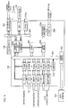
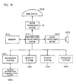
- FIG. 6 A specific example of the display platform section 6 shown in Fig. 6 will be described with reference to Fig. 4 .
- a display platform section 101 shown in Fig. 4 includes an LSI 102 which corresponds to the liquid crystal controller 11 (see Fig. 1 ).
- the LSI 102 is constituted by a BGA (Ball Grid Array) with 400 pins.
- image data is supplied through input terminals of 6 ports, and image data which has been subjected to various processes is supplied to the liquid crystal panel 7.
- the LSI 102 includes an image quality improvement circuit 102a corresponding to the liquid crystal image quality improvement circuit 14 (see Fig. 1 ). With this image improvement circuit 102a, the image data is subjected to image quality improvement before being supplied to the liquid crystal panel 7.
- the LSI 102 is connected to, via a CPU bus 107 and a CPU bus 109, (i) a CAN (Controller Area Network) microcomputer 103 corresponding to the DPF microcomputer 9 (see Fig. 1 ) and (ii) an image memory 104 which is constituted by four 32-bit DDRSDRAMs and corresponds to the display data memory 15 (see Fig. 1 ).
- the bit width of this image memory 104 may be 8 bits, 16 bits, or more.
- the types of the image memory 104 may be DDR2, XDR, or the like.
- the CAN microcontroller 103 is control means which obtains state information of the vehicle via a single-system CAN LAN 105 corresponding to the in-vehicle LAN 31 (see Fig. 1 ), so as to control the processing of the image data carried out by the LSI 102.
- the CAN LAN 105 may be plural (2, 3, or more) systems in order to receive inputs from other information systems of the vehicle. While obtaining vehicle information via the CAN LAN 105, the CAN microcontroller 103 directly obtains vehicle information from a GPIO (General-Purpose Input/Output) 106. This GPIO 106 is directly connected to members such as gears, indicators, and a device for generating alarm sound such as a buzzer and a speaker.
- GPIO General-Purpose Input/Output
- the image memory 104 is constituted by 4 DDRSDRAMs. Image data is written or read out into/from the image memory 104 by the LSI 102, as circumstances demand.
- a flash memory 108 is connected to the general-purpose CPU bus 107 between the LSI 102 and the CAN microcontroller 103.
- This flash memory 108 stores data of still images and programs for, for example, simulation of the instrument panel display system.
- the programs and the data of still images, which are stored in the flash memory 108, are read out by the LSI 102, as circumstances demand.
- the LSI 102 is connected to an EEPROM 110 to which, for example, an error at the time of executing a simulation program is written as a log. In other words, the LSI 102 performs fault diagnosis with reference to the log which has been written into the EEPROM 110.
- the LSI 102 inputs and outputs debug information of the inside of the LSI 102 by JTAG (Joint Test Action Group).
- the display platform section 101 is provided with: a power source circuit 111 corresponding to the power source circuit 18; and a gradation voltage generation circuit 112 and a COM circuit 113 corresponding to the timing generator 12. Also, although being not illustrated, a circuit for controlling the backlight of the liquid crystal panel 7, which corresponds to the backlight control circuit 13, is provided.
- 6-port image data is supplied to an internal memory bus 201 via a Scaler.
- image data for drawing meters is supplied via a DVI (Digital Visual Interface), and is enlarged or reduced to a predetermined size by the Scaler. Then the image data is supplied to the memory bus 201.
- image data from a PC is supplied via the DVI, and enlarged or reduced to a predetermined size by the Scaler. The image data is then supplied to the memory bus 201.
- the image data of both systems is supplied via a HDCP (High-bandwidth Digital Content Protection) and enlarged or reduced to a predetermined size by the Scaler, and then the image data is supplied to the memory bus 201.
- HDCP High-bandwidth Digital Content Protection
- Image data supplied from CCD cameras is two-system NTSC (National Television System Committee) signals. Such signals are supplied to the Scaler via a decoder and a capture, and enlarged or reduced to a predetermined size by the Scaler. The signals are then supplied to the memory bus 201.
- NTSC National Television System Committee
- the LSI 102 can handle sets of image data from 16 CCD cameras in total. This can be achieved by using 16 capture buffers. Details of the input of image data from the CCD cameras will be given later.
- Each of the input interfaces DVI and HDCP may be other interfaces such as LCDS, HDMI (High-Definition Multimedia Interface), GVIF (Gigabit Video Inter-Face), digital RGB, analog RGB, and D1/D2/D3/D4.
- LCDS High-Definition Multimedia Interface
- GVIF Gigabit Video Inter-Face
- digital RGB digital RGB
- analog RGB digital RGB
- D1/D2/D3/D4 D1/D2/D3/D4.
- the inputs from the CCD cameras may be typical television inputs.
- the television standard may be PAL or SECAM rather than NTSC.
- the image data supplied to the memory bus 201 is temporarily stored in the DDRSDRAM in the image memory 104, by a memory control section 202 which performs memory control in the memory bus 201.
- a memory control section 202 controls the writing of image data into the image memory 104
- the arbitration of memory access from each Scaler to the memory bus 201 is carried out by an arbiter 203.
- the memory bus 201 is connected to a drawing controller 204 serving as a drawing controller, a bitblt 205 for image transmission, and an alpha blend 206 for overlapping images.
- the drawing controller 204 is further connected to a control bus 207 which is controlled by the CAN microcontroller 103.
- the control bus 207 is connected to a flash memory 108 for initial data, an SPI (Serial Peripheral Interface) for writing into the EEPROM 110 information for a log (e.g. parameter setting information), which is supplied via the drawing controller 204, and a JTAG for sending to a JTAG a signal for debug.
- SPI Serial Peripheral Interface
- the alpha blend 206 is connected to the image quality improvement circuit 102a, and image data having been subjected to the alpha blend process is subjected to image quality improvement.
- the image data after the image quality improvement is supplied to the liquid crystal panel 7 via a LVDSTX (transmitter) 208.
- the image data having been converted to have a predetermined size by each scalar is written into a port memory 0 or 1 (top side) which is provided in units of ports. Simultaneously, data corresponding to a window to be displayed is read out in units of Planes from each port memory Plane 1 or 2 (bottom side), and simultaneously a blend process (alpha blend) corresponding to overlapped windows and alpha values is conducted.
- the image data having been alpha-blended is supplied to the image quality improvement circuit on the subsequent stage, and then supplied to the liquid crystal panel 7 via the LVDS.
- LVDS digital RGB, RSDS, analog RGB, or the like may be adopted.
- top side and bottom side indicate that 3 Frames (corresponding to Planes 0/1/2 in Fig. 6 ) including a buffer of asynchronous processing are sequentially switched after the completion of reading/writing (i.e. reading and writing cannot be simultaneously done to a single Flame). In this case, it is assumed that the speed of reading is equal to or higher than the speed of writing.
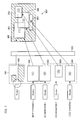
- Fig. 7 schematically shows the flow of a process of overlapping images.
- Fig. 8 shows an image obtained by the overlap process of Fig. 7 .
- LSI 102 On the side from which input to the memory bus 201 is carried out, there are sets of image data supplied via respective ports of the LSI 102, which are meter drawing information, car navigation 1 information, car navigation 2 information, and CCD camera information. These sets of information are dealt with as moving images, and are converted to have desired display sizes by the Scalers. The display sizes are determined in accordance with a control signal supplied from the CAN microcontroller 103.
- the meter drawing is converted to a first image 301 corresponding to an window (1) in the figure
- the car navigation 1 is converted to a second image 302 corresponding to an window (2) in the figure
- the car navigation 2 is converted to a third image 303 corresponding to an window (3) in the figure
- an image from a CCD camera is converted to a fourth image 304 corresponding to an window (4) in the figure.
- the converted images are temporarily stored in the image memory 104.
- a still image 305 such as a background image has been subjected to display size conversion by the Scaler and bitblt 205, and has been stored in the image memory 104 in advance.
- the sets of image data stored in the image memory 104 are alpha-blended and are read out, so that a single image 300 in which windows overlap with one another is generated.
- the alpha blend is, as shown in Fig. 8 , a process to overlap windows in units of pixels.
- the image 300 shown in Fig. 8 has parts where displayed images do not overlap one another and parts where portions of images overlap with one another, and the overlapped portions have been alpha-blended.
- a portion 306 where the first image 301 overlaps the second image 302 and a portion 307 where the second image 302 overlaps the third image are alpha-blended.
- the overlapping portion of the second image 302 is made to be transparent in order to show the overlapping portion of the first image 301 and the overlapping portion of the third image 303.
- the windows can be freely provided and can be overlapped with one another without the alpha blend.
- two images are displayed in a transparent manner (both of the images are transparent).
- two images are displayed in a non-transparent manner. In other words, when the alpha blend is not carried out, two images look like two nontransparent sheets which overlap with one another.
- the CAN microcontroller 103 judges the states of the vehicle (S1).
- the CAN microcomputer 103 judges the states of the vehicle (car) with reference to information (drawing information) indicating the state of the car, which information is supplied from each LAN.
- the drawing information includes, for example, instruction information which instructs to display a navigation image or to display a speedometer.
- the states of the vehicle include all kinds of information related to the vehicle, such as speed, engine revolutions, oil quantity, open/close of doors, turning on/off of air conditioner, and turning on/off of audio.
- the CAN microcontroller 103 determines if it is necessary to change the currently-displayed layout (S2). In this case, the CAN microcontroller 103 carries out the determination with reference to the states of the vehicle judged in the step S 1.
- the CAN microcontroller 103 activates a layout generation program (S4).
- the CAN microcontroller 103 activates a layout generation program which (i) corresponds to the display layout thus determined, (ii) has been read out from the flash memory 108 in advance, and h(iii) as been loaded onto a DRAM.
- the flash memory 108 stores, for respective display layouts, layout generation programs for generating patterns of display layouts shown in Fig. 3 . The programs are loaded onto the DRAM at the time of the boot.
- the CAN microcontroller 103 determines which display layout is adopted, with reference to the obtained drawing information, and then activates a layout generation program for generating the selected display layout.
- Each layout generation program at least includes: information regarding types of images to be displayed (e.g. a navigation image, a moving image such as a speedometer, and a still image such as a background image); information regarding the sizes of images to be displayed (e.g. 640 pixels ⁇ 480 pixels); information regarding the positions of images to be displayed (e.g. the location of the upper-left corner of an image and the aspect ratio of an image); the ratios of the alpha blend of images to be displayed (e.g. a navigation image and a speedometer are alpha-blended in the ratio of 60% and 40%).
- types of images to be displayed e.g. a navigation image, a moving image such as a speedometer, and a still image such as a background image
- information regarding the sizes of images to be displayed e.g. 640 pixels ⁇ 480 pixels
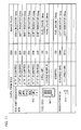
- each layout generation program generates a layout with reference to the following table 1 showing alpha blend ratios.
- Table 1 Window Numbers of Images alpha blend Values (1) 20% (2) 40% (3) 30% (4) 100%
- the degree of transparency of the window (1) is 20%
- that of the window (2) is 40%
- the ratio of transparency of the window (2) is 40%, that of the window (3) is 30%, and that of the background 305 is 30%.
- the window (4) is not transparent because the alpha blend value thereof is 100%.
- the description above deals with a case where two images are overlapped with one another.
- the CAN microcontroller 103 instructs, via the drawing controller 204, a Scaler to enlarge or reduce to a predetermined size an image supplied from the DVI, HDC, or the capture buffer.
- the Scaler enlarges or reduces the image to the instructed size and outputs the image to the DDRSDRAM of the image memory 104.
- the CAN microcontroller 103 outputs to the bitblt 205 a control signal for obtaining image data from the image memory 104.
- the CAN microcomputer 104 outputs to the bitblt 205 a control signal for generating an image in which images are provided at predetermined positions, based on the information which is included in the layout generation program and relates to the positions of the images.
- the bitblt 205 generates data for overlapping images (S5). That is, with reference to the control signal supplied from the CAN microcontroller 103, the bitblt 205 generates image data for the overlap of windows and outputs the generated image data to the alpha blend 206.
- Fig. 7 which illustrates the process to overlap windows
- the following sets of image data are read out from the respective faces and generated: first image data which occupies the entirety of a window (1); second image data which occupies the entirety of a window (2); third image data which occupies the entirety of a window (3); and fourth image data which occupies the entirety of a window (4).
- the bitblt outputs those sets of image data thus generated to the alpha blend 206.
- the alpha blend 206 carries out the alpha blend process (S6). More specifically, the alpha blend 206 carries out an alpha-blend overlap process of obtained plural sets of image data, based on the ratios of the alpha blend informed by the CAN microprocessor 103. As a result, for example, data of a single image shown in Fig. 8 is generated and the layout generation program is terminated. According to another method, sets of images data of respective faces are read out and an alpha blend process is simultaneously carried out, so that data of a single image is generated.
- the image data is subjected to predetermined processes in the image quality improvement 102a and the LCDSTx 208, and then supplied to the liquid crystal panel 7.
- the liquid crystal panel 7 displays an image based on the supplied image data.
- the liquid crystal panel 7 displays moving images and still images.
- the generation of the layout in the liquid crystal panel 7 is assumed as a main event, whereas changes in image display in each image on the layout is assumed as sub events.
- the images are provided on the liquid crystal panel 7.
- the images displayed in the respective windows are changed.
- Fig. 11(a) indicates the main event of the scene design A
- Fig. 11(b) shows sub events of the scene design A.
- a fuel gauge 401 and a shift indicator 402 are displayed as components constituting the scene design A.
- Fig. 11(b) shows that 10 (bitmap) images for changing the display of the fuel gauge 401 are registered and 6 (bitmap) images for changing the display of the shift indicator 402 are also registered.
- Fig. 12 shows a table in which components used in sub events are associated with sets of information determined in the main event.
- Fig. 12 shows that 6 types of image files are registered in association with the lighting states of the shift indicator 402 indicating the shift indicator ECU, 10 types of image files are registered in association with the scale mark 8 of the fuel gauge 401 indicating the fuel ECU, and 2 types of image files are registered in association with the lighting states of the indicator 403 indicating the indicator ECU.
- These image files have component numbers (SEN), respectively.
- the shift indicator ECU and the fuel ECU execute sub events corresponding to the changes, so that the images in the scene design A are changed.
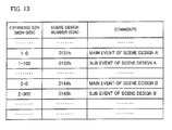
- Each scene design is generated with reference to a scene design table shown in Fig. 13 .
- the scene design numbers (SDN) of the scene design table are associated with respective commends in a command table.
- a scene design is specified by a MEN (Main Event Number) indicating the layout of a component and a SEN (Sub Event Number) indicating the number of the component.
- a MEN and a SEN are selected by the user.
- a scene design number SDN of each scene design is set as a combination of a MEN and a SEN.
- a main event indicates that the layout is switched when the vehicle is running, has stopped, and is going back, as shown in Fig. 3 .
- Event numbers, i.e. MENs are allocated to the respective layouts. Sub events indicate that the looks of the components (e.g. shift position and fuel amount) are changed.
- a table shown in Fig. 14 is used. That is, a combination of a MEN and a SEN is used as an expanded scene design number (expanded SDN).
- the LSI 102 having received an expanded SDN from the CAN microcontroller 103 converts the expanded SDN into a scene design number SDN which is actually used, and the LSI 102 executes an event.
- the layout displayed on the liquid crystal display panel 7 is controlled in accordance with each scene design. That is, as shown in Fig. 15 , scene designs in which a main event is associated with sub events are set in advance, and a program corresponding to each scene design is executed.
- the source data for generating the above-described scene design A is arranged as shown in Fig. 16 .
- the drawing (a) of the background and the drawing (b) of the fuel gauge are carried out in the main event, whereas the drawing (c) of details of the state of the fuel gauge is carried out in the sub event.
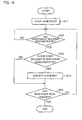
- the LSI 102 executes a main event in accordance with an instruction from the CAM microprocessor 103, so as to display a scene design on the liquid crystal panel 7 (S11).
- the LSI 102 determines whether a control signal supplied from the CAN microcomputer 103 includes an instruction to execute a sub event (S12). If such an instruction to execute a sub event is included, it is determined whether the instructed sub event is included in the scene design which is currently displayed on the liquid crystal panel 7 (S13).
- the LSI 102 determines whether the SEN which is included in the control signal supplied from the CAN microcontroller 103 is identical with the SEN in the scene design which is currently displayed.
- the LSI 102 determines that the supplied SEN does not exist in the scene design A and hence does not process the same. In other words, sub events which do not exist in the currently-displayed scene design A are not processed.
- the LSI 102 executes the sub event of the shift indicator of the scene design A, so that a part of the image display is updated.
- the memory amount above is small in comparison with memory amount required for rewriting the whole screen each time, i.e. in case where partial rewriting of the screen is not carried out. In other words, the memory amount is smaller than memory amount required for rewriting the whole screen each time.
- memory amount in a case where a sub event is not adopted is calculated by (number of main events + number of sub events) ⁇ memory amount for whole screen.
- Memory amount in case where a sub event is adopted is calculated by number of main events ⁇ memory amount of whole screen + number of sub events ⁇ memory amount for sub event images. In this case, provided that memory amount of images rewritten in a sub event is, for example, 20% of the whole screen, the memory amount is reduced by the number of sub events ⁇ (100%-20%).
- the multi display real-time processing circuit 8 functioning as display control means is provided with an image layout table.
- Image layout data is generated using the image layout table and images indicating respective sets of information are listed, so that the burden on the multi display real-time processing circuit 8 is reduced.
- Instrument panel display images includes still images and moving images, and are displayed at display positions determined by an image layout. These sets of image data are, as described above, generated in a shared manner by the processors (of the vehicle system 3, the amenity system 4, and the safety system 5), and are supplied to the display platform section 6 via the in-vehicle LAN 31.
- the image layout data of an instrument panel display image is generated not on the processors side but on the display platform section 6 side. On this account, such image layout data does not pass through the in-vehicle LAN 31.
- the communications traffic on the in-vehicle LAN 31 can be reduced in such a manner that image data of still images constituting an instrument panel display image is dealt with on the display platform section 6 side.
- the still images are, for example, the background image in a meter part (the meter in the meter part is a moving image) in a case of a speedometer, and the background image of a fuel gauge.
- still images can be stored on both sides without any problems.
- still images are preferably stored in the display platform section 6.
- the display data memory 15 is included in the liquid crystal controller 11 in the display platform section 6, and this display data memory 15 includes a background image storage section 15a for storing data for displaying a background image and an image layout table 15b for generating image layout data.
- image data for generating still images is stored in the display data memory 15, whereas image data for generating moving images is obtained from the processors.
- the technical idea of the present invention can be adopted not only to a display system mounted on a movable body but also to other uses.
- the technical idea of the present invention can be expressed as a display system for displaying plural sets of information as images, in which sets of data for displaying the images are generated in a shared manner by plural processors.
- the display system of the present invention can be broadly used as an information display system for vehicles such as cars and trains, airplanes, ships, and the like.
Applications Claiming Priority (2)
| Application Number | Priority Date | Filing Date | Title |
|---|---|---|---|
| JP2004244413 | 2004-08-24 | ||
| EP05772901.4A EP1800959B1 (fr) | 2004-08-24 | 2005-08-18 | Systeme d'affichage |
Related Parent Applications (2)
| Application Number | Title | Priority Date | Filing Date |
|---|---|---|---|
| EP05772901.4 Division | 2005-08-18 | ||
| EP05772901.4A Division-Into EP1800959B1 (fr) | 2004-08-24 | 2005-08-18 | Systeme d'affichage |
Publications (1)
| Publication Number | Publication Date |
|---|---|
| EP2204302A1 true EP2204302A1 (fr) | 2010-07-07 |
Family
ID=35967404
Family Applications (2)
| Application Number | Title | Priority Date | Filing Date |
|---|---|---|---|
| EP10158773A Withdrawn EP2204302A1 (fr) | 2004-08-24 | 2005-08-18 | Système d'affichage |
| EP05772901.4A Not-in-force EP1800959B1 (fr) | 2004-08-24 | 2005-08-18 | Systeme d'affichage |
Family Applications After (1)
| Application Number | Title | Priority Date | Filing Date |
|---|---|---|---|
| EP05772901.4A Not-in-force EP1800959B1 (fr) | 2004-08-24 | 2005-08-18 | Systeme d'affichage |
Country Status (6)
| Country | Link |
|---|---|
| US (2) | US8004395B2 (fr) |
| EP (2) | EP2204302A1 (fr) |
| JP (4) | JP4455594B2 (fr) |
| KR (3) | KR20070055561A (fr) |
| CN (3) | CN101633318A (fr) |
| WO (1) | WO2006022191A1 (fr) |
Cited By (1)
| Publication number | Priority date | Publication date | Assignee | Title |
|---|---|---|---|---|
| EP4098978A3 (fr) * | 2021-10-14 | 2023-05-10 | Apollo Intelligent Connectivity (Beijing) Technology Co., Ltd. | Procédé et appareil de traitement de données pour véhicule, dispositif électronique et support |
Families Citing this family (76)
| Publication number | Priority date | Publication date | Assignee | Title |
|---|---|---|---|---|
| CN101633318A (zh) * | 2004-08-24 | 2010-01-27 | 夏普株式会社 | 显示系统 |
| KR100663474B1 (ko) * | 2005-10-26 | 2007-01-02 | 삼성전자주식회사 | 휴대용 단말기에서 주행 중 멀티미디어 방송 데이터를처리하는 방법 |
| DE102005059616A1 (de) * | 2005-12-12 | 2007-06-14 | Robert Bosch Gmbh | Verfahren, Kommunikationssystem, Multimedia-Teilnehmer und Gateway zum Übertragen von im MPEG-Format vorliegenden Multimedia-Daten |
| CN101405162B (zh) | 2006-03-31 | 2011-08-03 | 夏普株式会社 | 车载用仪表面板显示系统、图像数据输出装置 |
| US8199167B2 (en) * | 2006-05-15 | 2012-06-12 | Sharp Kabushiki Kaisha | Diagnostic support device and diagnostic support system |
| CN101489833A (zh) | 2006-08-11 | 2009-07-22 | 夏普株式会社 | 车载用显示系统、显示面板控制装置 |
| US8094003B2 (en) * | 2006-11-22 | 2012-01-10 | Sharp Kabushiki Kaisha | Display control unit, on-vehicle display system, display controller, and on-vehicle display |
| JP4286876B2 (ja) * | 2007-03-01 | 2009-07-01 | 富士通テン株式会社 | 画像表示制御装置 |
| US8819673B1 (en) | 2007-05-24 | 2014-08-26 | United Services Automobile Association (Usaa) | Systems and methods for java virtual machine management |
| CN101784429B (zh) * | 2007-07-26 | 2012-11-28 | 庞巴迪动力产品公司 | 操作车辆的方法 |
| DE102007038544A1 (de) * | 2007-08-16 | 2009-02-19 | Robert Bosch Gmbh | Kommunikationsverfahren und Schnittstelle zwischen einem Begleit-Chip und einem Mikrokontroller |
| JP4967984B2 (ja) * | 2007-10-22 | 2012-07-04 | 株式会社デンソー | 車両用表示装置 |
| EP2213518A4 (fr) * | 2007-11-06 | 2010-12-22 | Sharp Kk | Système d'affichage, dispositif de sortie de données d'affichage, dispositif de commande d'affichage, procédé de commande d'affichage, programme de commande d'affichage et support d'enregistrement lisible par ordinateur |
| JPWO2009066494A1 (ja) * | 2007-11-20 | 2011-04-07 | シャープ株式会社 | 表示制御装置、再現装置、移動体用情報表示システム、操縦席用モジュール、および移動体 |
| JP2009154647A (ja) * | 2007-12-26 | 2009-07-16 | Aisin Aw Co Ltd | マルチ画面表示装置及びそのプログラム |
| EP2241861A4 (fr) | 2008-01-22 | 2013-02-27 | Sharp Kk | Système d'affichage, dispositif de commande d'affichage, dispositif d'affichage d'image |
| CN101348100B (zh) * | 2008-07-28 | 2011-02-16 | 奇瑞汽车股份有限公司 | 车辆中央信息显示装置及其显示方法 |
| JP5225157B2 (ja) * | 2009-02-27 | 2013-07-03 | 株式会社日立製作所 | 車載システム |
| JP2010282015A (ja) * | 2009-06-04 | 2010-12-16 | Funai Electric Co Ltd | 表示装置 |
| US8350682B2 (en) * | 2009-06-12 | 2013-01-08 | Mack Trucks, Inc. | DPF warning system |
| DE102010021343A1 (de) * | 2009-09-04 | 2011-03-10 | Volkswagen Ag | Verfahren und Vorrichtung zum Bereitstellen von Informationen in einem Fahrzeug |
| US20110080278A1 (en) * | 2009-10-06 | 2011-04-07 | Ford Global Technologies, Llc | System And Method For Customizing An Information Display Within A Vehicle |
| KR101274712B1 (ko) * | 2009-11-05 | 2013-06-12 | 네스트리 주식회사 | 입체 영상 표시 장치 |
| US20110144857A1 (en) * | 2009-12-14 | 2011-06-16 | Theodore Charles Wingrove | Anticipatory and adaptive automobile hmi |
| US8718897B2 (en) * | 2010-03-29 | 2014-05-06 | Wrightspeed, Inc. | Vehicle dynamics control in electric drive vehicles |
| JP5587032B2 (ja) * | 2010-05-24 | 2014-09-10 | 矢崎総業株式会社 | 車両用表示装置 |
| JP5501110B2 (ja) * | 2010-06-16 | 2014-05-21 | 矢崎総業株式会社 | 画像表示装置 |
| JP2012007829A (ja) * | 2010-06-25 | 2012-01-12 | Sharp Corp | 加熱調理器 |
| KR101337855B1 (ko) * | 2011-01-04 | 2013-12-06 | 주식회사 만도 | 스위치 고장 검출 장치 및 그 검출 방법 |
| EP2509332B1 (fr) * | 2011-04-04 | 2015-12-30 | AGUSTAWESTLAND S.p.A. | Système de test automatique pour systèmes d'affichage numérique |
| US8981968B2 (en) * | 2011-07-22 | 2015-03-17 | The Boeing Company | User-defined pages for aircraft |
| DE102011081901A1 (de) | 2011-08-31 | 2013-02-28 | Bayerische Motoren Werke Aktiengesellschaft | Verfahren zum Betreiben einer Steuervorrichtung für ein Display eines Fahrzeugs und Steuervorrichtung |
| JP2013052817A (ja) * | 2011-09-06 | 2013-03-21 | Toyota Motor Corp | 車両用ストリームデータ管理システム |
| US20140081493A1 (en) * | 2011-11-19 | 2014-03-20 | Electric Motor Werks, Inc. | Modular instrumentation system for electric vehicle data acquisition, analysis and display, and component control |
| EP2868529B1 (fr) * | 2012-06-27 | 2021-04-14 | Nippon Seiki Co., Ltd. | Dispositif de fourniture d'informations pour véhicule |
| JP5923726B2 (ja) * | 2012-07-25 | 2016-05-25 | パナソニックIpマネジメント株式会社 | 表示制御装置、及び、表示制御システム |
| CN103630375B (zh) * | 2012-08-27 | 2017-06-23 | 深圳市金溢科技股份有限公司 | 一种车载单元的故障诊断方法、车载单元和系统 |
| CN103714787A (zh) * | 2012-09-28 | 2014-04-09 | 比亚迪股份有限公司 | 一种液晶仪表的显示方法以及汽车的液晶显示装置 |
| JP6036228B2 (ja) * | 2012-11-30 | 2016-11-30 | 株式会社デンソー | 車両用映像処理装置および車両用映像処理システム |
| US10235117B2 (en) | 2013-01-31 | 2019-03-19 | Mitsubishi Electric Corporation | Display control system |
| SE537045C2 (sv) * | 2013-04-09 | 2014-12-16 | BAE Systems Hägglunds Aktiebolag | Distribuerad displayanordning för fordon samt objekt försettmed distribuerad displayanordning |
| CN104281461B (zh) * | 2013-07-09 | 2018-05-22 | 合肥杰发科技有限公司 | 一种开机显示控制方法及装置 |
| WO2015011807A1 (fr) * | 2013-07-24 | 2015-01-29 | 富士通株式会社 | Système, procédé et programme d'affichage |
| EP2846253A1 (fr) * | 2013-09-05 | 2015-03-11 | Continental Automotive GmbH | Fonctionnement d'un dispositif de commande avec un dispositif d'affichage séparé dans un véhicule |
| DE102013016089B4 (de) * | 2013-09-27 | 2023-09-07 | Audi Ag | Kraftfahrzeug mit Fahrerassistenzsystemen und Verfahren zum Betrieb von Fahrerassistenzsystemen |
| CN104724004B (zh) * | 2013-12-24 | 2017-10-13 | 坦亿有限公司 | 车辆系统的接口切换装置、方法与车辆系统 |
| DE102014001182A1 (de) * | 2014-01-30 | 2015-07-30 | Audi Ag | System zur Bedienung eines Kombiinstruments eines Fahrzeugs und einer mobilen elektronischen Vorrichtung, die lösbar von einer fahrzeugseitigen Halterung gehaltert werden kann |
| DE102014203059A1 (de) | 2014-02-20 | 2015-08-20 | Bayerische Motoren Werke Aktiengesellschaft | Verfahren zur Bestimmung eines Master-Zeitsignals, Fahrzeug und System |
| JP6295924B2 (ja) | 2014-03-18 | 2018-03-20 | 株式会社デンソー | 車両用報知制御装置、及び車両用報知制御システム |
| JP6343188B2 (ja) | 2014-07-01 | 2018-06-13 | クラリオン株式会社 | 情報提示装置、情報提示方法、及びプログラム |
| JP2016039387A (ja) * | 2014-08-05 | 2016-03-22 | 株式会社デンソー | 映像信号処理装置及び映像信号処理プログラム |
| JP6401990B2 (ja) * | 2014-09-30 | 2018-10-10 | 矢崎総業株式会社 | 車両用表示装置 |
| FI127221B (en) * | 2014-10-17 | 2018-01-31 | Rightware Oy | Dynamic rendering of graphics |
| CN106794770B (zh) * | 2014-10-29 | 2019-12-31 | 三菱马恒达农机有限公司 | 作业用行驶车辆 |
| CN105015346B (zh) * | 2015-06-18 | 2017-11-10 | 江苏新通达电子科技股份有限公司 | 带有语音提示功能的虚拟汽车仪表系统、工作方法及汽车 |
| CN105015344B (zh) * | 2015-06-18 | 2017-12-05 | 江苏新通达电子科技股份有限公司 | 一种全虚拟汽车仪表系统、工作方法及安装该系统的汽车 |
| CN105034808B (zh) * | 2015-06-18 | 2017-10-13 | 江苏新通达电子科技股份有限公司 | 一种双系统全虚拟汽车仪表系统、工作方法及汽车 |
| CN105034987B (zh) * | 2015-06-18 | 2017-11-10 | 江苏新通达电子科技股份有限公司 | 适于快速启动的全虚拟汽车仪表系统、工作方法及汽车 |
| JP6439052B2 (ja) | 2015-08-26 | 2018-12-19 | 富士フイルム株式会社 | 投写型表示装置 |
| JP6687361B2 (ja) * | 2015-10-28 | 2020-04-22 | ラピスセミコンダクタ株式会社 | 半導体装置、映像表示システムおよび映像信号の出力方法 |
| JP6578901B2 (ja) | 2015-11-13 | 2019-09-25 | 株式会社デンソー | 表示制御装置 |
| DE102015224943A1 (de) * | 2015-12-11 | 2017-06-14 | Bayerische Motoren Werke Aktiengesellschaft | Vorrichtung zur Anzeige von Hinweisen in Kraftfahrzeugen |
| JP6690375B2 (ja) * | 2016-04-12 | 2020-04-28 | 日本精機株式会社 | 車載表示装置 |
| JP6658391B2 (ja) * | 2016-08-02 | 2020-03-04 | 株式会社デンソー | 車両用映像表示システム |
| US10559217B2 (en) * | 2016-08-05 | 2020-02-11 | Intel Corporation | Methods and apparatus to develop in-vehicle experiences in simulated environments |
| CA3047135A1 (fr) * | 2016-12-30 | 2018-08-09 | Nuscale Power, Llc | Systemes et procedes de protection de reacteur nucleaire |
| CN106926799B (zh) * | 2017-03-24 | 2019-10-22 | 广东小天才科技有限公司 | 汽车安全提醒方法及装置 |
| CN107161007A (zh) * | 2017-06-16 | 2017-09-15 | 上海赫千电子科技有限公司 | 一种车辆仪表与中控的一体化设备及方法 |
| CN109961730A (zh) * | 2017-12-26 | 2019-07-02 | 南京瀚宇彩欣科技有限责任公司 | 显示系统及其驱动方法 |
| JP7040238B2 (ja) | 2018-04-06 | 2022-03-23 | 株式会社Jvcケンウッド | 表示制御装置、車両用表示装置、表示制御方法およびプログラム |
| FR3084634B1 (fr) * | 2018-08-01 | 2021-07-30 | Renault Sas | Systeme d'affichage d'informations par selection manuelle ou automatique parmi une pluralite de modes d'affichage classes par en fonction de leur niveau de decentrage par rapport au vehicule |
| JP7419689B2 (ja) * | 2018-08-10 | 2024-01-23 | 株式会社デンソー | 車両用電子制御システム、センター装置、車両用マスタ装置、表示制御情報の送信制御方法、表示制御情報の受信制御方法、表示制御情報の送信制御プログラム及び表示制御情報の受信制御プログラム |
| JP2020117103A (ja) * | 2019-01-24 | 2020-08-06 | トヨタ自動車株式会社 | 車両用表示装置 |
| JP7120143B2 (ja) * | 2019-04-22 | 2022-08-17 | 株式会社デンソー | 車両用装置、車両用装置の制御方法 |
| JP2022067459A (ja) * | 2020-10-20 | 2022-05-06 | avatarin株式会社 | システム、端末及びプログラム |
| WO2023249132A1 (fr) * | 2022-06-20 | 2023-12-28 | 엘지전자 주식회사 | Dispositif d'affichage de véhicule, véhicule le comprenant et procédé de fonctionnement correspondant |
Citations (4)
| Publication number | Priority date | Publication date | Assignee | Title |
|---|---|---|---|---|
| EP0771686A2 (fr) * | 1995-11-06 | 1997-05-07 | Toyota Jidosha Kabushiki Kaisha | Dispositif d'affichage d'informations pour véhicules |
| DE19935892A1 (de) * | 1999-07-30 | 2001-02-08 | Bosch Gmbh Robert | Verfahren und Vorrichtung zur Anzeige von Fahrerinformationen in einem Kraftfahrzeug |
| EP1134718A2 (fr) * | 2000-02-29 | 2001-09-19 | Matsushita Electric Industrial Co., Ltd. | Sytème d'acquisition d'image et système embarqué de capteur sur véhicule |
| EP1178394A2 (fr) * | 2000-08-02 | 2002-02-06 | Calsonic Kansei Corporation | Dispositif de commande d'affichage |
Family Cites Families (37)
| Publication number | Priority date | Publication date | Assignee | Title |
|---|---|---|---|---|
| JPS6258110A (ja) | 1985-09-09 | 1987-03-13 | Mazda Motor Corp | 車両用多重表示装置 |
| US4845495A (en) * | 1988-02-17 | 1989-07-04 | Allied-Signal Inc. | Integrated avionics control and display arrangement |
| JPH01245363A (ja) * | 1988-03-28 | 1989-09-29 | Hitachi Ltd | データ処理装置 |
| IE60444B1 (en) * | 1988-03-30 | 1994-07-13 | Elverex Ltd | A software verification apparatus |
| JPH01309542A (ja) | 1988-06-08 | 1989-12-13 | Sharp Corp | ローカルエリアネットワーク |
| JPH04201676A (ja) | 1990-11-30 | 1992-07-22 | Koufu Kashio Kk | 列車運行管理装置 |
| JPH04273016A (ja) | 1991-02-28 | 1992-09-29 | Omron Corp | 車両用情報表示装置 |
| JPH04328420A (ja) | 1991-04-26 | 1992-11-17 | Nippondenso Co Ltd | 車両用表示装置 |
| US5366376A (en) * | 1992-05-22 | 1994-11-22 | Atari Games Corporation | Driver training system and method with performance data feedback |
| US5504482A (en) * | 1993-06-11 | 1996-04-02 | Rockwell International Corporation | Automobile navigation guidance, control and safety system |
| JP3180632B2 (ja) | 1995-09-08 | 2001-06-25 | 三菱自動車工業株式会社 | 自動車用多重表示装置 |
| JPH10297319A (ja) | 1997-05-01 | 1998-11-10 | Furukawa Electric Co Ltd:The | インパネ画像作成装置およびその方法 |
| JP3539150B2 (ja) * | 1997-09-02 | 2004-07-07 | トヨタ自動車株式会社 | ナビゲーション制御装置 |
| JP3777790B2 (ja) | 1998-04-28 | 2006-05-24 | 株式会社デンソー | 表示制御装置 |
| JP3224782B2 (ja) * | 1998-08-03 | 2001-11-05 | インターナショナル・ビジネス・マシーンズ・コーポレーション | 処理分担動的変更方法及びコンピュータ |
| WO2000014714A1 (fr) * | 1998-09-04 | 2000-03-16 | Innovative Solutions And Support Inc. | Ecran plat a uc pour habitacle d'aeronef |
| JP2000194583A (ja) | 1998-12-25 | 2000-07-14 | Nissin Electric Co Ltd | 監視制御システム、および、そのプログラムが記録された記録媒体 |
| JP2000238552A (ja) | 1999-02-19 | 2000-09-05 | Yazaki Corp | 車両用計器及びその計器表示方法、計器表示プログラムを記憶した記録媒体 |
| JP2001121989A (ja) | 1999-10-22 | 2001-05-08 | Yokogawa Electric Corp | 車両用情報表示装置 |
| JP2001320616A (ja) | 2000-02-29 | 2001-11-16 | Matsushita Electric Ind Co Ltd | 撮像システム |
| JP2001343929A (ja) | 2000-06-02 | 2001-12-14 | Canon Inc | 画像表示装置 |
| JP4618522B2 (ja) | 2000-11-22 | 2011-01-26 | マツダ株式会社 | 車両の故障表示装置 |
| US6812942B2 (en) * | 2000-12-28 | 2004-11-02 | International Business Machines Corporation | Context-responsive in-vehicle display system |
| JP4826030B2 (ja) | 2001-06-07 | 2011-11-30 | 株式会社デンソー | 映像信号生成装置及びナビゲーション装置 |
| JP2003137007A (ja) | 2001-11-05 | 2003-05-14 | Denso Corp | 車両用計器 |
| JP4011949B2 (ja) * | 2002-04-01 | 2007-11-21 | キヤノン株式会社 | マルチ画面合成装置及びデジタルテレビ受信装置 |
| JP2003309509A (ja) | 2002-04-12 | 2003-10-31 | Sumitomo Electric Ind Ltd | 車内通信システム、車内通信装置、及び通信装置 |
| JP2003320911A (ja) | 2002-04-26 | 2003-11-11 | Sumitomo Electric Ind Ltd | 車載制御システム、制御装置、及び中継装置 |
| JP2004157434A (ja) | 2002-11-08 | 2004-06-03 | Calsonic Kansei Corp | 車両用表示装置 |
| JP2004155395A (ja) | 2002-11-08 | 2004-06-03 | Denso Corp | 車両周辺画像処理装置 |
| KR101168423B1 (ko) * | 2003-02-05 | 2012-07-25 | 가부시키가이샤 자나비 인포메틱스 | 내비게이션 장치의 경로 탐색 방법 및 교통 정보 표시 방법 |
| US7075541B2 (en) * | 2003-08-18 | 2006-07-11 | Nvidia Corporation | Adaptive load balancing in a multi-processor graphics processing system |
| JP2005205997A (ja) | 2004-01-21 | 2005-08-04 | Denso Corp | 車載システム |
| JP4568087B2 (ja) * | 2004-01-28 | 2010-10-27 | 矢崎総業株式会社 | 車両用表示装置 |
| CN101633318A (zh) * | 2004-08-24 | 2010-01-27 | 夏普株式会社 | 显示系统 |
| US7420476B2 (en) * | 2005-01-07 | 2008-09-02 | Raytheon Company | Programmable cockpit upgrade system |
| JP4251141B2 (ja) | 2005-02-23 | 2009-04-08 | 株式会社デンソー | 計器および計器の指針表示方法 |
-
2005
- 2005-08-18 CN CN200910145233A patent/CN101633318A/zh active Pending
- 2005-08-18 CN CNB2005800279555A patent/CN100519275C/zh not_active Expired - Fee Related
- 2005-08-18 CN CN2009101452325A patent/CN101654067B/zh not_active Expired - Fee Related
- 2005-08-18 EP EP10158773A patent/EP2204302A1/fr not_active Withdrawn
- 2005-08-18 KR KR1020077006686A patent/KR20070055561A/ko not_active Application Discontinuation
- 2005-08-18 KR KR1020087015972A patent/KR20080067021A/ko active Search and Examination
- 2005-08-18 EP EP05772901.4A patent/EP1800959B1/fr not_active Not-in-force
- 2005-08-18 US US11/574,148 patent/US8004395B2/en not_active Expired - Fee Related
- 2005-08-18 JP JP2006531858A patent/JP4455594B2/ja not_active Expired - Fee Related
- 2005-08-18 WO PCT/JP2005/015086 patent/WO2006022191A1/fr active Application Filing
- 2005-08-18 KR KR1020087032068A patent/KR100970073B1/ko not_active IP Right Cessation
-
2008
- 2008-03-04 JP JP2008054125A patent/JP5148328B2/ja not_active Expired - Fee Related
- 2008-03-04 JP JP2008054124A patent/JP5148327B2/ja not_active Expired - Fee Related
- 2008-03-04 JP JP2008054123A patent/JP5148326B2/ja not_active Expired - Fee Related
-
2009
- 2009-03-18 US US12/406,374 patent/US20090179745A1/en not_active Abandoned
Patent Citations (4)
| Publication number | Priority date | Publication date | Assignee | Title |
|---|---|---|---|---|
| EP0771686A2 (fr) * | 1995-11-06 | 1997-05-07 | Toyota Jidosha Kabushiki Kaisha | Dispositif d'affichage d'informations pour véhicules |
| DE19935892A1 (de) * | 1999-07-30 | 2001-02-08 | Bosch Gmbh Robert | Verfahren und Vorrichtung zur Anzeige von Fahrerinformationen in einem Kraftfahrzeug |
| EP1134718A2 (fr) * | 2000-02-29 | 2001-09-19 | Matsushita Electric Industrial Co., Ltd. | Sytème d'acquisition d'image et système embarqué de capteur sur véhicule |
| EP1178394A2 (fr) * | 2000-08-02 | 2002-02-06 | Calsonic Kansei Corporation | Dispositif de commande d'affichage |
Non-Patent Citations (1)
| Title |
|---|
| BAUDISCH P ET AL: "Multiblending: displaying overlapping windows simultaneously without the drawbacks of alpha blending", CHI 2004; [CHI CONFERENCE PROCEEDINGS. HUMAN FACTORS IN COMPUTING SYSTEMS], VIENNA, AUSTRIA, 24 April 2004 (2004-04-24), pages 367 - 374, XP002458875, ISBN: 9781581137026 * |
Cited By (1)
| Publication number | Priority date | Publication date | Assignee | Title |
|---|---|---|---|---|
| EP4098978A3 (fr) * | 2021-10-14 | 2023-05-10 | Apollo Intelligent Connectivity (Beijing) Technology Co., Ltd. | Procédé et appareil de traitement de données pour véhicule, dispositif électronique et support |
Also Published As
| Publication number | Publication date |
|---|---|
| KR100970073B1 (ko) | 2010-07-16 |
| CN101654067B (zh) | 2013-04-24 |
| US20090179745A1 (en) | 2009-07-16 |
| CN101633318A (zh) | 2010-01-27 |
| CN101654067A (zh) | 2010-02-24 |
| KR20080067021A (ko) | 2008-07-17 |
| CN100519275C (zh) | 2009-07-29 |
| JP5148326B2 (ja) | 2013-02-20 |
| WO2006022191A1 (fr) | 2006-03-02 |
| EP1800959A1 (fr) | 2007-06-27 |
| JP2008197666A (ja) | 2008-08-28 |
| US20080309474A1 (en) | 2008-12-18 |
| EP1800959A4 (fr) | 2009-12-02 |
| KR20070055561A (ko) | 2007-05-30 |
| JP2008239145A (ja) | 2008-10-09 |
| JPWO2006022191A1 (ja) | 2008-05-08 |
| CN101031455A (zh) | 2007-09-05 |
| JP2008197667A (ja) | 2008-08-28 |
| JP5148327B2 (ja) | 2013-02-20 |
| EP1800959B1 (fr) | 2014-10-01 |
| JP5148328B2 (ja) | 2013-02-20 |
| JP4455594B2 (ja) | 2010-04-21 |
| US8004395B2 (en) | 2011-08-23 |
| KR20090006884A (ko) | 2009-01-15 |
Similar Documents
| Publication | Publication Date | Title |
|---|---|---|
| EP1800959B1 (fr) | Systeme d'affichage | |
| US7965177B2 (en) | Display system, screen design setting tool, display system program, screen design setting program, and recording medium | |
| US8073620B2 (en) | On-vehicle display system and display panel control device | |
| CN101278332B (zh) | 显示系统、显示装置和显示方法 | |
| KR100842546B1 (ko) | 시뮬레이션 장치, 시뮬레이션 프로그램, 시뮬레이션 방법 | |
| US7969294B2 (en) | Onboard display device, onboard display system and vehicle | |
| US10235117B2 (en) | Display control system | |
| US20110090074A1 (en) | Vehicular meter unit and display device | |
| US20100283597A1 (en) | Display system, display control device and image display device | |
| US20090135199A1 (en) | Display system, display system display control method, data display program, and recording medium | |
| CN117097852A (zh) | 一种汽车电子仪表屏的图标显示方法及装置 |
Legal Events
| Date | Code | Title | Description |
|---|---|---|---|
| PUAI | Public reference made under article 153(3) epc to a published international application that has entered the european phase |
Free format text: ORIGINAL CODE: 0009012 |
|
| AC | Divisional application: reference to earlier application |
Ref document number: 1800959 Country of ref document: EP Kind code of ref document: P |
|
| AK | Designated contracting states |
Kind code of ref document: A1 Designated state(s): AT BE BG CH CY CZ DE DK EE ES FI FR GB GR HU IE IS IT LI LT LU LV MC NL PL PT RO SE SI SK TR |
|
| 17P | Request for examination filed |
Effective date: 20110106 |
|
| 17Q | First examination report despatched |
Effective date: 20110825 |
|
| STAA | Information on the status of an ep patent application or granted ep patent |
Free format text: STATUS: THE APPLICATION IS DEEMED TO BE WITHDRAWN |
|
| 18D | Application deemed to be withdrawn |
Effective date: 20131123 |