EP1900608B1 - Steering assistance device for vehicle - Google Patents
Steering assistance device for vehicle Download PDFInfo
- Publication number
- EP1900608B1 EP1900608B1 EP06780900A EP06780900A EP1900608B1 EP 1900608 B1 EP1900608 B1 EP 1900608B1 EP 06780900 A EP06780900 A EP 06780900A EP 06780900 A EP06780900 A EP 06780900A EP 1900608 B1 EP1900608 B1 EP 1900608B1
- Authority
- EP
- European Patent Office
- Prior art keywords
- gain
- steering
- steering angle
- feedback
- change
- Prior art date
- Legal status (The legal status is an assumption and is not a legal conclusion. Google has not performed a legal analysis and makes no representation as to the accuracy of the status listed.)
- Expired - Fee Related
Links
Images


Classifications
-
- B—PERFORMING OPERATIONS; TRANSPORTING
- B62—LAND VEHICLES FOR TRAVELLING OTHERWISE THAN ON RAILS
- B62D—MOTOR VEHICLES; TRAILERS
- B62D5/00—Power-assisted or power-driven steering
- B62D5/04—Power-assisted or power-driven steering electrical, e.g. using an electric servo-motor connected to, or forming part of, the steering gear
- B62D5/0457—Power-assisted or power-driven steering electrical, e.g. using an electric servo-motor connected to, or forming part of, the steering gear characterised by control features of the drive means as such
- B62D5/046—Controlling the motor
- B62D5/0463—Controlling the motor calculating assisting torque from the motor based on driver input
Definitions
- the present invention relates to a steering assist apparatus for a vehicle which imparts assist force generated by an electric motor to steering of steerable wheels performed through rotation of a steering wheel.
- a steering assist apparatus of such a type is known to be configured such that in order to prevent unnecessary drive and control of the electric motor, assist torque generated by the electric motor is reduced or generation of assist torque is stopped by lowering the control voltage applied to the electric motor when the rack bar reaches the vicinity of its stroke end.
- Document JP 11 321 691 A describes an electric assist steering system having a motor current controller with gain scheduler.
- the motor controller controls the operation of an electric motor.
- the motor controller includes sensors for sensing at least one dynamic operating characteristic of the motor and for providing a signal indicative of the at least one sensed dynamic motor operating characteristic.
- a variable gain regulator receives a current command request signal having a value and provides a motor current control signal having a value functionally related to the value of the received current command request signal and a gain control value.
- the gain scheduler is operatively coupled to the variable gain regulator and to the sensor for providing the game control value to the variable game regulator in response to the sensed at least one dynamic motor operating characteristic to thereby control the amount of gain of the variable gain regulator.
- the motor controller further includes a drive circuit operatively connected to the variable gain regulator and the motor for energising the motor in response to the motor current control signal.
- the present invention addresses the problem of deterioration of steering feel and the problem of generation of abnormal noise at a steering mechanism portion from the steering wheel to the steerable wheels.
- control for the electric motor is tuned in accordance with the characteristics of the steering mechanism such that, within a range of ordinary steering angle, no abnormal noise is generated in the steering mechanism in a state where the control responsiveness of the electric motor is rendered high, when the steering angle becomes large, overcompensation occurs in operation of the steering mechanism for a large variation in the output torque of the electric motor, and abnormal noise is generated.
- the present invention has been accomplished in order to cope with the above-described problem, and an object of the present invention is to provide a steering assist apparatus for a vehicle which suppresses generation of abnormal noise by a steering mechanism without deteriorating steering feel.
- the present invention provides a steering assist apparatus for a vehicle which includes an electric motor for imparting assist force to steering of steerable wheels performed through rotation of a steering wheel, wherein feedback control is performed, while an actual control quantity of the electric motor is used as a feedback, such that the electric motor operates in accordance with a target control quantity, the steering assist apparatus being characterized by comprising steering angle detection means for detecting steering angle of the steering wheel; and gain changing means for changing a feedback gain used in the feedback control in accordance with the detected steering angle.
- the feedback gain may be a control gain regarding at least one of a proportional term or an integral term associated with the feedback control.
- the gain changing means may be configured such that when the detected steering angle is large, the feedback gain is changed to a smaller value as compared with the case where the detected steering angle is small, to thereby reduce abnormal noise which is generated due to high responsiveness of the feedback control.
- the gain changing means may be configured such that when the detected steering angle is large, the feedback gain is changed to a larger value as compared with the case where the detected steering angle is small, to thereby reduce abnormal noise which is generated due to low responsiveness of the feedback control.
- the target control quantity of the electric motor may be a target current value, which represents target current to be supplied to the electric motor.
- the actual control quantity of the electric motor is an actual current value, which represents current flowing through the electric motor and detected by means of a current sensor.
- the steering assist apparatus for a vehicle further comprises steering torque detection means for detecting steering torque applied to the steering wheel; vehicle speed detection means for detecting vehicle speed; and target-control-quantity determination means for determining the target control quantity of the electric motor in accordance with the detected steering torque and vehicle speed, whereby the target control quantity of the electric motor is determined by the steering torque and the vehicle speed.
- the gain-changing means changes the feedback gain used in the feedback control in accordance with the steering angle.
- the gain changing means changes the feedback gain such that when the steering angle of the steering wheel is large, the feedback gain is changed to a smaller value as compared with the case where the steering angle is small, to thereby reduce abnormal noise which is generated due to high responsiveness of the feedback control.
- the gain changing means changes the feedback gain such that when the steering angle of the steering wheel is large, the feedback gain is changed to a larger value as compared with the case where the steering angle is small, to thereby reduce abnormal noise which is generated due to low responsiveness of the feedback control.
- a control quantity used to make the actual control quantity of the electric motor approach the target control quantity is changed without changing the target control quantity, whereby the rate of change of the electric motor from the current state to a state corresponding to the target control quantity is controlled to decrease or increase when the steering angle becomes large and the output torque of the electric motor becomes large.
- the control for the electric motor is tuned in accordance with the characteristics of the steering mechanism such that, within a range of ordinary steering angle, no abnormal noise is generated in the steering mechanism in a state where the control responsiveness of the electric motor is rendered high, when the steering angle increases, the control quantity fed back to the electric motor is controlled to decrease, and the output torque of the electric motor becomes difficult to change, so that generation of abnormal noise due to overcompensation of the steering mechanism is suppressed.
- the control for the electric motor is tuned in accordance with the characteristics of the steering mechanism such that, within the range of ordinary steering angle, no abnormal noise is generated in the steering mechanism in a state where the control responsiveness of the electric motor is rendered low
- the control quantity fed back to the electric motor is controlled to increase, and the output torque of the electric motor becomes easy to change, so that no response delay is produced in the output torque of the electric motor in relation to operation of the steering mechanism, whereby generation of abnormal noise is suppressed.
- a second feature of the present invention resides in that the gain changing means changes the feedback gain from a first feedback gain to a second feedback gain when the steering angle detected by the steering angle detection means becomes greater than a predetermined steering angle, and there are further provided steering speed detection means for detecting steering speed of the steering wheel; and gain-change control means for permitting the gain changing means to change the feedback gain when the steering speed detected by the steering speed detection means is lower than a predetermined steering speed and prohibiting the gain changing means from changing the feedback gain when the detected steering speed is equal to or higher than the predetermined steering speed.
- a third feature of the present invention resides in that hysteresis is imparted to the feedback-gain changing control performed by the gain changing means and the gain-change control means in accordance with changes in the steering angle detected by the steering angle detection means and the steering speed detected by the steering speed detection means.
- a fourth feature of the present invention resides in that the gain changing means changes the feedback gain from a first feedback gain to a second feedback gain when the steering angle detected by the steering angle detection means becomes greater than a predetermined steering angle; the target current value decreases as the vehicle speed increases; and there is further provided gain-change control means for permitting the gain changing means to change the feedback gain when current flowing through the electric motor is greater than a predetermined current and prohibiting the gain changing means from changing the feedback gain when the current flowing through the electric motor is equal to or less than the predetermined current.
- the target current value or the actual current value may be used as the current flowing through the electric motor.
- the feedback gain is not switched. In other words, even when the steering angle of the steering wheel is large, if the vehicle speed is high, the feedback gain is not switched. As a result, even when the feedback gain is set so as to prevent generation of abnormal noise from the steering mechanism during periods in which the vehicle stops or travels at very low speed and the steering wheel is steered greatly, the feedback gain is not switched during periods in which the vehicle travels at high speed, whereby deterioration of steering feel can be prevented.
- a fifth feature of the present invention resides in that hysteresis is imparted to the feedback-gain changing control performed by the gain changing means and the gain-change control means in accordance with changes in the steering angle detected by the steering angle detection means and the current flowing through the electric motor.
- a sixth feature of the present invention resides in that the gain changing means changes the feedback gain from a first feedback gain to a second feedback gain when the steering angle detected by the steering angle detection means becomes greater than a predetermined steering angle; and there are provided current-change-rate detection means for detecting, as a current change rate, the ratio of a change rate of the current flowing through the electric motor to a change rate of the steering torque detected by the steering torque detection means, and gain-change control means for permitting the gain changing means to change the feedback gain when the current change rate detected by the current-change-rate detection means is greater than a predetermined change rate and prohibiting the gain changing means from changing the feedback gain when the detected current change rate is equal to or less than the predetermined change rate.
- the target current value or the actual current value may be used as the current flowing through the electric motor.
- the current change rate represents the magnitude of change in torque generated by the electric motor for a required assist torque; i.e., a state where abnormal noise is likely to be generated, by an increase in its value.
- the current change rate is small, the switching of the feedback gain by the gain changing means is prohibited, and when the current change rate becomes large, the switching of the feedback gain by the gain changing means is permitted. As result, the feedback gain become more likely to be switched in a state where abnormal noise is likely to be generated, whereby reduction of abnormal noise and good steering feel are realized simultaneously.
- a seventh feature of the present invention resides in that hysteresis is imparted to the feedback-gain changing control performed by the gain changing means and the gain-change control means in accordance with changes in the steering angle detected by the steering angle detection means and the current change rate detected by the current-change-rate calculation means.
- An eighth feature of the present invention resides in that the gain changing means changes the feedback gain from a first feedback gain to a second feedback gain when the steering angle detected by the steering angle detection means becomes greater than a predetermined steering angle; and there is provided gain-change control means for permitting the gain changing means to change the feedback gain when the vehicle speed detected by the vehicle speed detection means is lower than a predetermined vehicle speed and prohibiting the gain changing means from changing the feedback gain when the vehicle speed is equal to or higher than the predetermined vehicle speed.
- a ninth feature of the present invention resides in that hysteresis is imparted to the feedback-gain changing control performed by the gain changing means and the gain-change control means in accordance with changes in the steering angle detected by the steering angle detection means and the vehicle speed detected by the vehicle speed detection means.
- a tenth feature of the present invention resides in that the gain changing means includes low-pass-filer processing means for performing low-pass-filter processing for the feedback gain changed in accordance with the steering angle.
- the feedback gain gradually changes after being switched, so that even when the feedback gain is changed by the gain changing means, the response characteristic of assist force generated by the electric motor changes smoothly, so that the driver does not feel any unnatural sensation when he rotates the steering wheels.
- FIG. 1 is a schematic diagram showing the entirety of a steering apparatus for a vehicle which includes a steering assist apparatus according to the present invention.
- This steering apparatus for a vehicle includes a steering shaft 12, an upper end of which is connected to a steering wheel 11 such that the steering shaft 12 rotates together with the steering wheel 11.
- a pinion gear 13 is connected to a lower end of the steering shaft 12 such that the pinion gear 13 rotates together with the steering shaft 12.
- the pinion gear 13 is in meshing engagement with rack teeth formed on a rack bar 14 to thereby form a rack and pinion mechanism.
- Left and right front wheels FW1 and FW2 are steerably connected to opposite ends of the rack bar 14 via unillustrated tie rods and knuckle arms.
- the left and right front wheels FW1 and FW2 are steered leftward or rightward in accordance with an axial displacement of the rack bar 14 caused by rotation of the steering shaft 12 about its axis.
- An electric motor 15 for steering assist is assembled to the rack bar 14.
- the electric motor 15 is connected to the rack bar 14 via a ball-screw mechanism 16 in a power transmissible manner.
- the electric motor 15 assists steering of the left and right front wheels FW1 and FW2 through rotation thereof.
- the ball-screw mechanism 16 which functions as a speed reducer and a rotation-rectilinear motion converter, converts rotational motion of the electric motor 15 to rectilinear motion, while reducing the rotational speed, and transmits the rectilinear motion to the rack bar 14.
- the electric motor 15 may be assembled to the steering shaft 12 in such a manner as to transmit rotation of the electric motor 15 to the steering shaft 12 via a speed reducer, to thereby drive the steering shaft 12 about its axis.
- the electric control apparatus includes a steering torque sensor 21, a steering angle sensor 22, and a vehicle speed sensor 23.
- the steering torque sensor 21 is assembled to the steering shaft 12 and adapted to detect steering torque T which acts on the steering shaft 12 as a result of an operation of rotating the steering wheel 11.
- the steering torque T assumes a positive or negative value depending on whether the left and right front wheels FW1 and FW2 are steered rightward or leftward, and the magnitude of the positive or negative value represents the magnitude of the steering torque T.
- the steering torque sensor 21 may be assembled to the rack bar 14 so as to detect the steering torque T from an amount of distortion of the rack bar 14 in the axial direction.
- the steering angle sensor 22 is assembled to the steering shaft 12 and adapted to detect actual steering angle ⁇ of the steering wheel 11 by detecting rotational angle of the steering shaft 12.
- the actual steering angle ⁇ assumes a positive or negative value depending on whether the steering wheel 11 is rotated clockwise or counterclockwise, and the magnitude of the positive or negative value represents the magnitude of the actual steering angle ⁇ .
- the steering angle sensor 22 may be assembled to the rack bar 14 so as to detect the actual steering angle ⁇ from an amount of displacement of the rack bar 14 in the axial direction. Further, since the rotational angle of the electric motor 15 is proportional to the actual steering angle ⁇ , the actual steering angle ⁇ may be detected from the rotational angle of the electric motor 15.
- the vehicle speed sensor 23 detects vehicle speed V.
- the steering torque sensor 21, the steering angle sensor 22, and the vehicle speed sensor 23 are connected to an electronic control unit 24.
- the electronic control unit 24 is mainly formed by a microcomputer composed of a CPU, ROM, RAM, etc.
- the electronic control unit 24 drives the electric motor 15 via a drive circuit 25 by means of various computer program controls to be described later.
- the drive circuit 25 receives a control voltage value E 0 from the electronic control unit 24 and supplies to the electric motor 15 a current proportional to the control voltage value E 0 , to thereby cause the electric motor 15 to generate an assist torque proportional to the control voltage value E 0 .
- a current sensor 25a is provided in the drive circuit 25.
- the current sensor 25a detects actual current value I, which represents the magnitude of current flowing through the electric motor 15, and supplies the same to the electronic control unit 24.
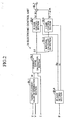
- FIG. 2 is a functional block diagram of the electronic control unit 24 according to this first control example.
- a target-current-value determination section BL1 determines a target current value I*, which changes in accordance with the steering torque T and the vehicle seed V, while referring to a target-current-value table by use of the steering torque T detected by the steering torque sensor 21 and the vehicle speed V detected by the vehicle speed sensor 23.
- This target-current-value table is previously stored in the ROM in the electronic control unit 24.
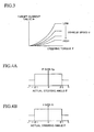
- the target-current-value table stores a target current value I* which increases non-linearly with the steering torque T.
- the target current value I* may be calculated by use of a previously prepared function which represents the target current value I*, which changes in accordance with the steering torque T and the vehicle speed V.
- the thus-determined target current value I* is supplied to a current-error calculation section BL2.
- This current-error calculation section BL2 receives the actual current value I detected by the current sensor 25a.
- the integral calculation section BL3 performs integral calculation on the current error ⁇ I, which changes with elapse of time, and supplies the current error ⁇ I having undergone the integral calculation to an I-gain control section BL5 (i.e., integral-term-gain control section BL5).
- a PI-gain setting section BL6 (i.e., proportional/integral-control-gain setting section BL6) sets P gain Kp and I gain Ki, which change in accordance with the actual steering angle ⁇ , while referring to a P-gain table (i.e., proportional-term-gain table) and an I-gain table (integral-term-gain table) by making use of the actual steering angle ⁇ detected by the steering angle sensor 22.
- P-gain table and I-gain tables are previously provided in the ROM of the electronic control unit 24. As shown in FIGS.
- the P-gain table and I-gain table store the P gain Kp and the I gain Ki, each of which assumes a large value when the absolute value
- the P gain Kp and the I gain Ki may be calculated by use of previously prepared functions which respectively represent the P gain Kp and the I gain Ki, which change in accordance with the actual steering angle ⁇ .
- the P-gain control section BL4 outputs to an adding section BL7 a proportional control value Kp ⁇ I, which is obtained by multiplying the current error ⁇ I supplied from the current error calculation section BL2 by the P gain Kp supplied from the PI-gain setting section BL6.
- the I-gain control section BL5 outputs to the adding section BL7 an integral control value Ki ⁇ Idt, which is obtained by multiplying the current error integral value ⁇ Idt supplied from the integral calculation section BL3 by the I gain Ki supplied from the PI-gain setting section BL6.
- the adding section BL7 adds the proportional control value Kp ⁇ I and the integral control value Ki ⁇ Idt together, and outputs the resultant value Kp ⁇ I + Ki ⁇ Idt to the drive circuit 25 as the control voltage value E 0 .
- the drive circuit 25 supplies to the electric motor 15 a drive current proportional to the control voltage value E 0 , and feedback-controls the rotation of the electric motor 15. Accordingly, the electric motor 15 rotates and outputs a rotational torque proportional to the control voltage value E 0 .
- the rotation of the electric motor 15 is transmitted to the ball-screw mechanism 16, which converts rotational motion of the electric motor 15 to rectilinear motion, while reducing the rotational speed, and drives the rack bar 14 in the axial direction.
- driver's operation of rotating the steering wheel 11 is assisted by means of the electric motor 15, so that the left and right front wheels FW1 and FW2 are steered by a steering force applied by the driver and an assist force generated by the electric motor 15.
- the driver can rotate the steering wheel 11 while being assisted by the assist force generated by the electric motor 15.
- the electric motor 15 is driven and controlled in accordance with the target current value I*, and a control quantity for the electric motor 15 required in a state where the actual steering angle ⁇ is large is secured, so that steering feel does not deteriorate.
- of the actual steering angle ⁇ is equal to or smaller than the predetermined steering angle ⁇ 1
- the P gain Kp and the I gain Ki are set to respective large values.
- the control responsiveness of the electric motor 15 is maintained high so long as the absolute value
- the gains Kp and Ki which are feedback gains, are changed to smaller values.
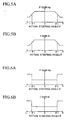
- the P-gain and I-gain tables which respectively store the P gain Kp and the I gain Ki, each of which changes from a first value to a second value when the absolute value
- P-gain and I-gain tables which respectively store a P gain Kp and an I gain Ki, each of which gradually changes from a large value to a small value as the absolute value
- P-gain and I-gain tables which respectively store a P gain Kp and an I gain Ki, each of which gradually changes from a small value to a large value as the absolute value
- the control for the electric motor 15 may be tuned such that no abnormal noise is generated from the steering mechanism, composed of the electric motor 15, the ball-screw mechanism 16, and the rack bar 14, in a state where the control responsiveness (i.e., frequency responsiveness) of the electric motor 15 is high and the absolute value
- the control for the electric motor 15 is tuned in accordance with the characteristics of the steering mechanism such that no abnormal noise is generated from the steering mechanism, by means of lowering the control responsiveness (i.e., frequency responsiveness) of the electric motor 15 within a range in which the absolute value
- the electric motor 15 is feedback-controlled by making use of both the P gain Kp and the I gain Ki.
- the electric motor 15 may be feedback-controlled by making use of only one of the P gain Kp and the I gain Ki.
- the electric motor 15 may be feedback-controlled by making use of only one of the P gain Kp and the I gain Ki in the other control examples as well.
- FIG. 8 shows a functional block diagram of the electronic control unit 24 according to this second control example.
- the block diagram of FIG. 8 differs from that of FIG. 2 in that a steering-angle determination section BL8 is added to a stage preceding to the PI-gain setting section BL6.
- the PI-gain setting section BL6 of FIG. 8 differs in function from the PI-gain setting section BL6 of FIG. 2 , the remaining sections are identical with those of the functional block diagram of FIG. 2 . Therefore, only portions different from the first control example will be described, and descriptions of the remaining portions will not be repeated.
- the steering-angle determination section BL8 repeatedly executes, at predetermined short intervals, a steering-angle determination program of FIG. 9 , which is composed of steps S10 to S15, so as to set a flag FLG to "0" or "1."
- the flag FLG is used to determine conditions for setting the P gain and the I gain. That is, the steering-angle determination section BL8 acquires the actual steering angle ⁇ from the steering angle sensor 22, and sets the flag FLG to "0" when the absolute value
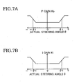
- the PI-gain setting section BL6 repeatedly executes, at predetermined short intervals, a PI-gain setting program of FIG. 10 , which is composed of steps S20 to S24, so as to set the P gain Kp and the I gain Ki in accordance with the value of the flag FLG set by the steering-angle determination section BL8, with reference to a P-gain map and an I-gain map, respectively. That is, the P-gain map and the I-gain map are shown in FIG. 11 , and when the value of the flag FLG is "0," the P gain Kp and the I gain Ki are set to ordinary constants Kp1 and Ki1, respectively. When the value of the flag FLG is "1," the P gain Kp and the I gain Ki are set to abnormal-noise coping constants Kp2 and Ki2, respectively.
- the P-gain map and the I-gain map are prepared such that the noise coping constants Kp2 and Ki2 assume smaller values than do the ordinary constants Kp1 and Ki1, as in the case of the gain tables of FIGS. 4A and 4B .
- the P-gain map and the I-gain map are prepared such that the noise coping constants Kp2 and Ki2 assume larger values than do the ordinary constants Kp1 and Ki1, as in the gain tables of FIGS. 6A and 6B .
- these constants Kp1, Ki1, Kp2, and Ki2 are also used, and set in the above-described manner.
- the P gain Kp and the I gain Ki are switched from the ordinary constants Kp1 and Ki1 to the noise coping constants Kp2 and Ki2 as in the case of the above-described first control example. Therefore, in the second control example as well, like the case of the first control example, good steering feel is always maintained even when the actual steering angle ⁇ changes, and the generation of abnormal noise from the steering mechanism, composed of the ball-screw mechanism 16 and the rack bar 14, is always suppressed even when the actual steering angle ⁇ changes.
- FIG. 12 shows a functional block diagram of the electronic control unit 24 according to this third control example.
- the block diagram of FIG. 12 differs from that of FIG. 8 relating to the second embodiment in that the steering-angle determination section BL8 is replaced with a steering-speed calculation section BL9 and a gain-change-condition determination section BL10. Since the remaining portions, including the PI-gain setting section BL6, are identical with those of FIG. 8 , only portions different from the second control example will be described, and descriptions of the remaining portions will not be repeated.
- the steering-speed calculation section BL9 differentiates, with respect to time, the actual steering angle ⁇ acquired from the steering angle sensor 22 and calculates steering speed ⁇ of the steering wheel 11 (equivalent to the steering speed of the left and right front wheels FW1 and FW2 and the rotational speed of the electric motor 15).
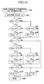
- the gain-change-condition determination section BL10 repeatedly executes, at predetermined short intervals, a gain-change-condition determination program of FIG. 13 , which is composed of steps S30 to S36, so as to set the flag FLG to "0" or "1" in accordance with the actual steering angle ⁇ and the steering speed ⁇ .
- the gain-change-condition determination section BL10 acquires the actual steering angle ⁇ from the steering angle sensor 22 and the calculated steering speed ⁇ , and sets the flag FLG to "0" when the absolute value
- the gain-change-condition determination section BL10 sets the flag FLG to "1" when the absolute value
- the P gain Kp and the I gain Ki are switched according to the second control example, the P gain Kp and the I gain Ki are not switched from the ordinary constants Kp1 and Ki1 to the noise coping constants Kp2 and Ki2 even when the absolute value
- the control responsiveness of the electric motor 15 is properly controlled, whereby generation of abnormal noise and occurrence of a failure in the steering mechanism can be prevented.
- the P gain Kp and the I gain Ki are not switched from the ordinary constants Kp1 and Ki1 to the noise coping constants Kp2 and Ki2; i.e., the P gain Kp and the I gain Ki are not switched from high values to low values, so that the control responsiveness of the electric motor 15 is maintained at the previously set high level, and generation of abnormal noise and occurrence of a failure in the steering mechanism are prevented.
- the P gain Kp and the gain Ki are not switched from the ordinary constants Kp1 and Ki1 to the noise coping constants Kp2 and Ki2; i.e., the P gain Kp and the I gain Ki are not switched from low values to high values, so that the control responsiveness of the electric motor 15 does not increase abruptly to an excessive degree, and generation of abnormal noise and occurrence of a failure in the steering mechanism are prevented.
- the third control example may be modified in such a manner as to impart hysteresis to the control of changing the P gain Kp and the I gain Ki in accordance with the actual steering angle ⁇ and the acquired steering speed ⁇ .
- the gain-change-condition determination section BL10 in place of the gain-change-condition determination program of FIG. 13 , repeatedly executes, at predetermined short intervals, a gain-change-condition determination program of FIG. 14 .
- the gain-change-condition determination section BL10 acquires the actual steering angle ⁇ and the steering speed ⁇ in step S41.
- the gain-change-condition determination section BL10 sets an end condition flag EFL to "0" or "1" in accordance with a change in the actual steering angle ⁇ . That is, as shown in FIG. 15A , in a state where the end condition flag EFL is set to "0," the gain-change-condition determination section BL10 changes the value of the flag EFL to "1" when the absolute value
- of the actual steering angle ⁇ exceeds the predetermined steering angle ⁇ 1 (e.g., 500 degrees).
- the gain-change-condition determination section BL10 changes the value of the flag EFL to "0" when the absolute value
- a predetermined steering angle ⁇ 2 e.g., 490 degrees
- the gain-change-condition determination section BL10 sets a steering-speed condition flag VFL to "0" or "1” in accordance with a change in the steering speed ⁇ . That is, as shown in FIG. 15B , in a state where the steering-speed condition flag VFL is set to "0," the gain-change-condition determination section BL10 changes the value of the steering-speed condition flag VFL to "1" when the absolute value
- the predetermined steering speed ⁇ 1 e.g., 100 degrees/sec.
- the gain-change-condition determination section BL10 changes the value of the steering-speed condition flag VFL to "0" when the absolute value
- a predetermined steering speed ⁇ 2 e.g. 200 degrees/sec
- the gain-change-condition determination section BL10 sets the flag FLG to "0" when the end condition flag EFL is “0" or the steering-speed condition flag VFL is "0.” Meanwhile, the gain-change-condition determination section BL10 sets the flag FLG to "1" when the end condition flag EFL is "1” and the steering-speed condition flag VFL is "1.”
- the PI gain setting section BL6 changes the P gain Kp and the I gain Ki in accordance with this flag FLG as in the case of the third control example. As a result, hysteresis is imparted to the control of changing the P gain Kp and the I gain Ki in accordance with changes in the actual steering angle ⁇ and steering speed ⁇ .
- the frequency of switching the P gain Kp and the I gain Ki is reduced as compared with changes in the actual steering angle ⁇ and the steering speed ⁇ .
- frequent switching of the P gain Kp and the I gain Ki i.e., frequent switching of the drive current supplied to the electric motor 15, is mitigated, and generation of abnormal noise in the steering mechanism is suppressed more effectively.
- FIG. 16 shows a functional block diagram of the electronic control unit 24 according to this fourth control example.
- the block diagram of FIG. 16 differs from that of FIG. 12 relating to the third control example in that the steering-speed calculation section BL9 is omitted, and in place of the steering speed ⁇ , the actual current value I, which represents current flowing through the electric motor 15 and detected by the current sensor 25a, is input to the gain-change-condition determination section BL10. Since the remaining portions are identical to those of FIG. 12 , only portions different from the third control example will be described, and descriptions of the remaining portions will not be repeated.
- the gain-change-condition determination section BL10 repeatedly executes, at predetermined short intervals, a gain-change-condition determination program of FIG. 17 , which is composed of steps S30 to S36, similar to those of FIG. 13 but steps S31 and S33 being replaced with steps S31a and S33a.
- step S31a the gain-change-condition determination section BL10 acquires the actual current value I from the current sensor 25a rather than the steering speed ⁇ used in the third control example.
- the gain-change-condition determination section BL10 determines whether or not the absolute value
- this predetermined current value I1 corresponds to a current which flows through the electric motor 15 when the steering wheel 11 is steered to a steering angle of about ⁇ 500 degrees in a state where the vehicle speed V is about 10 km/h (when switching of the P gain Kp and the I gain Ki is performed).
- the gain-change-condition determination section BL10 sets the flag FLG to "0" when the absolute value
- the P gain Kp and the I gain Ki are switched according to the second control example, the P gain Kp and the I gain Ki are not switched from the ordinary constants Kp1 and Ki1 to the noise coping constants Kp2 and Ki2 even when the absolute value
- the fourth control example may be modified in such a manner as to impart hysteresis to the control of changing the P gain Kp and the I gain Ki in accordance with the actual steering angle ⁇ and the actual current value I.
- the gain-change-condition determination section BL10 in place of the gain-change-condition determination program of FIG. 17 , repeatedly executes, at predetermined short intervals, a program modified from the gain-change-condition determination program of FIG. 14 .
- the gain-change-condition determination section BL10 acquires the actual current value I instead of the steering speed ⁇ in step S41, and performs the determination processing of step S33a of FIG. 17 rather than the determination processing of step S49. Further, instead of performing the determination processing of step S50, the gain-change-condition determination section BL10 determines whether or not the absolute value
- the gain-change-condition determination section BL10 proceeds to step S53.
- the above-described steering-speed condition flag VFL is to be read as a currant condition flag VFL.
- the frequency of switching the P gain Kp and the I gain Ki is reduced as compared with changes in the actual steering angle ⁇ and the actual current value I. Therefore, frequent switching of the P gain Kp and the I gain Ki; i.e., frequent switching of the drive current supplied to the electric motor 15, is mitigated, and generation of abnormal noise in the steering mechanism is suppressed more effectively.
- the actual current value I is used for the control of switching the P gain Kp and the I gain Ki.
- the target current value I* may be used, because the target current value I* is approximately equal to the actual current value I.
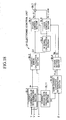
- FIG. 18 shows a functional block diagram of the electronic control unit 24 according to this fifth control example.
- the block diagram of FIG. 18 differs from that of FIG. 12 relating to the third control example in that a current-change-rate calculation section BL11 is used instead of the steering-speed calculation section BL9, and in place of the steering speed ⁇ , a current change rate lrt calculated by the current-change-rate calculation section BL11 is input to the gain-change-condition determination section BL10. Since the remaining portions are identical with those of FIG. 12 , only portions different from the third control example will be described, and descriptions of the remaining portions will not be repeated.
- the current-change-rate calculation section BL11 repeatedly executes, at predetermined short intervals, a current-change-rate calculation program of FIG. 19 , which is composed of steps S60 to S65, so as to calculate, as a current change rate lrt, the ratio of change rate of the target current value I* to change rate of the steering torque T. Specifically, in step S61, the current-change-rate calculation section BL11 acquires the steering torque T detected by the steering torque sensor 21 and the target current value I* determined by the target-current-value determination section BL1.
- step S62 the current-change-rate calculation section BL11 subtracts steering torque Told at the time of the previous processing from steering torque Tnew at the time of the current processing, and calculates, as a torque change ⁇ T, the absolute value
- step S63 the current-change-rate calculation section BL11 subtracts target current value I*old at the time of the previous processing from target current value I*new at the time of the current processing, and calculates, as a target-current change ⁇ I*, the absolute value
- step S64 the current-change-rate calculation section BL11 calculates the current change rate lrt by dividing the target-current change ⁇ I* by the torque change ⁇ T.
- the gain-change-condition determination section BL10 repeatedly executes, at predetermined short intervals, a gain-change-condition determination program of FIG. 20 , which is composed of steps S30 to S36, similar to those of FIG. 13 but with steps S31 and S33 being replaced with steps S31b and S33b.
- step S31b the gain-change-condition determination section BL10 acquires the current change rate lrt calculated by the current-change-rate calculation section BL11 rather than the steering speed ⁇ used in the third control example.
- the gain-change-condition determination section BL10 determines whether or not the current change rate lrt is greater than a predetermined current change rate lrt1 (e.g., 200 A/Nm).
- the gain-change-condition determination section BL10 sets the flag FLG to "0" when the absolute value
- the P gain Kp and the I gain Ki are switched according to the second control example, the P gain Kp and the I gain Ki are not switched from the ordinary constants Kp1 and Ki1 to the noise coping constants Kp2 and Ki2 even when the absolute value
- the current change rate lrt represents the magnitude of change in torque generated by the electric motor 15 for a required assist torque; i.e., a state where abnormal noise is likely to be generated, by an increase in its value.
- the fifth control example may be modified in such a manner as to impart hysteresis to the control of changing the P gain Kp and the I gain Ki in accordance with the actual steering angle ⁇ and the actual current value I.
- the gain-change-condition determination section BL10 in place of the gain-change-condition determination program of FIG. 20 , the gain-change-condition determination section BL10 repeatedly executes, at predetermined short intervals, a program modified from the gain-change-condition determination program of FIG. 14 .
- the gain-change-condition determination section BL10 acquires the current change rate lrt instead of the steering speed ⁇ in step S41, and performs the determination processing of step S33b of FIG. 20 rather than the determination processing of step S49. Further, instead of performing the determination processing of step S50, the gain-change-condition determination section BL10 determines whether or not the current change rate lrt is less than a predetermined current change rate lrt2, which is smaller than the predetermined current change rate lrt1. When the current change rate lrt is less than the predetermined current change rate lrt2, the gain-change-condition determination section BL10 proceeds to step S52.
- the gain-change-condition determination section BL10 proceeds to step S53.
- the above-described steering-speed condition flag VFL is to be read as a current-change-rate condition flag VFL.
- the frequency of switching the P gain Kp and the I gain Ki for changes in the actual steering angle ⁇ and the current change rate lrt is decreased. Accordingly, the frequent switching of the P gain Kp and the I gain Ki; i.e., the frequent switching of the drive current supplied to the electric motor 15, is mitigated, whereby generation of abnormal noise from the steering mechanism can be suppressed more effectively.
- the target current value I* is used for the calculation of the current change rate lrt.
- the actual current value I may be used, because the target current value I* is approximately equal to the actual current value I.
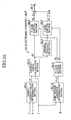
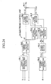
- FIG. 21 shows a functional block diagram of the electronic control unit 24 according to this sixth control example.
- the block diagram of FIG. 21 differs from that of FIG. 12 relating to the third control example in that the steering-speed calculation section BL9 is omitted, and in place of the steering speed ⁇ , the vehicle speed V detected by the vehicle speed sensor 23 is input to the gain-change-condition determination section BL10. Since the remaining portions are identical with those of FIG. 12 , only portions different from the third control example will be described, and descriptions of the remaining portions will not be repeated.
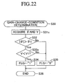
- the gain-change-condition determination section BL10 repeatedly executes, at predetermined short intervals, a gain-change-condition determination program of FIG. 22 , which is composed of steps S30 to S36, similar to those of FIG. 13 but with steps S31 and S33 being replaced with steps S31c and S33c.
- step S31c the gain-change-condition determination section BL10 acquires the vehicle speed V detected by the vehicle speed sensor 23 rather than the steering speed ⁇ used in the third control example.
- the gain-change-condition determination section BL10 determines whether or not the vehicle speed V is less than a predetermined vehicle speed V1 (e.g., 10 km/h).
- the gain-change-condition determination section BL10 sets the flag FLG to "0" when the absolute value
- the P gain Kp and the I gain Ki are switched according to the second control example, the P gain Kp and the I gain Ki are not switched from the ordinary constants Kp1 and Ki1 to the noise coping constants Kp2 and Ki2 even when the absolute value
- the sixth control example may be modified in such a manner as to impart hysteresis to the control of changing the P gain Kp and the ⁇ gain Ki in accordance with the actual steering angle ⁇ and the vehicle speed V.
- the gain-change-condition determination section BL10 in place of the gain-change-condition determination program of FIG. 22 , repeatedly executes, at predetermined short intervals, a program modified from the gain-change-condition determination program of FIG. 14 .
- the gain-change-condition determination section BL10 acquires the vehicle speed V instead of the steering speed ⁇ in step S41, and performs the determination processing of step S33c of FIG. 22 rather than the determination processing of step S49. Further, instead of performing the determination processing of step S50, the gain-change-condition determination section BL10 determines whether or not the vehicle speed V is greater than a predetermined vehicle speed V2 (e.g., 20 km/h), which is higher than the predetermined vehicle speed V1. When the vehicle speed V is greater than the predetermined vehicle speed V2, the gain-change-condition determination section BL10 proceeds to step S52.
- a predetermined vehicle speed V2 e.g. 20 km/h
- the gain-change-condition determination section BL10 proceeds to step S53.
- the above-described steering-speed condition flag VFL is to be read as a vehicle-speed condition flag VFL.
- the frequency of switching the P gain Kp and the I gain Ki for changes in the actual steering angle ⁇ and the vehicle speed V is decreased. Accordingly, the frequent switching of the P gain Kp and the I gain Ki; i.e., the frequent switching of the drive current supplied to the electric motor 15, is mitigated, whereby generation of abnormal noise from the steering mechanism can be suppressed well.
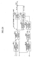
- FIGS. 23 to 28 respectively show functional blocks of modifications of the above-described first to sixth embodiments.
- a low pass filter processing section BL12 is disposed in a stage following the respective PI-gain setting section BL6 of the functional blocks of the first through sixth control examples shown in FIGS. 2 , 8 , 12 , 16 , 18 , and 21 .
- the low pass filter processing section BL12 successively acquires the P gain Kp and the I gain Ki set to the PI-gain setting section BL6, and outputs them to the P-gain control section BL4 and the I-gain control section BL5 after performing low-pass-filter processing on the P gain Kp and the I gain Ki.
- the P gain Kp and the I gain Ki by which the current error ⁇ I and its integral value ⁇ Idt are multiplied, are caused to change gradually, so that even when the P gain Kp and the I gain Ki are switched, the control voltage value E 0 changes smoothly, and the drive current flowing through the electric motor 15 also changes smoothly. Accordingly, even when the P gain Kp and the I gain Ki are switched, steering assist force generated by the electric motor 15 changes smoothly, and the driver does not feel unnatural sensation, which the driver would otherwise feel when rotating the steering wheel 11.
Applications Claiming Priority (2)
| Application Number | Priority Date | Filing Date | Title |
|---|---|---|---|
| JP2005200520A JP4367383B2 (ja) | 2005-07-08 | 2005-07-08 | 車両の操舵アシスト装置 |
| PCT/JP2006/313625 WO2007007694A1 (ja) | 2005-07-08 | 2006-07-03 | 車両の操舵アシスト装置 |
Publications (3)
| Publication Number | Publication Date |
|---|---|
| EP1900608A1 EP1900608A1 (en) | 2008-03-19 |
| EP1900608A4 EP1900608A4 (en) | 2008-12-10 |
| EP1900608B1 true EP1900608B1 (en) | 2010-02-17 |
Family
ID=37637085
Family Applications (1)
| Application Number | Title | Priority Date | Filing Date |
|---|---|---|---|
| EP06780900A Expired - Fee Related EP1900608B1 (en) | 2005-07-08 | 2006-07-03 | Steering assistance device for vehicle |
Country Status (9)
| Country | Link |
|---|---|
| US (1) | US7974752B2 (ja) |
| EP (1) | EP1900608B1 (ja) |
| JP (1) | JP4367383B2 (ja) |
| KR (1) | KR20080009158A (ja) |
| CN (1) | CN101218146B (ja) |
| BR (1) | BRPI0613826B1 (ja) |
| DE (1) | DE602006012320D1 (ja) |
| RU (1) | RU2376185C2 (ja) |
| WO (1) | WO2007007694A1 (ja) |
Families Citing this family (58)
| Publication number | Priority date | Publication date | Assignee | Title |
|---|---|---|---|---|
| US7828112B2 (en) * | 2006-05-26 | 2010-11-09 | Mitsubishi Electric Corporation | Electric power steering device |
| US8296011B2 (en) * | 2007-12-12 | 2012-10-23 | Steering Solutions IP Holding Corporations | Systems and methods involving quadrant dependent active damping |
| JP5401801B2 (ja) * | 2008-02-18 | 2014-01-29 | 日本精工株式会社 | 電動パワーステアリング装置 |
| JP5534292B2 (ja) * | 2008-06-30 | 2014-06-25 | 株式会社ジェイテクト | 車両用操舵装置 |
| KR101205685B1 (ko) * | 2008-07-23 | 2012-11-27 | 주식회사 만도 | 조향각 센서 및 이를 구비한 차량 시스템 |
| JP5376215B2 (ja) * | 2009-01-30 | 2013-12-25 | 株式会社ジェイテクト | モータ制御装置 |
| JP5223718B2 (ja) * | 2009-02-17 | 2013-06-26 | 株式会社デンソー | 操舵負荷推定装置及び電動パワーステアリング装置 |
| JP5495018B2 (ja) | 2009-03-12 | 2014-05-21 | 株式会社ジェイテクト | モータ制御装置 |
| JP4883134B2 (ja) * | 2009-05-15 | 2012-02-22 | 株式会社デンソー | 電動パワーステアリング制御装置 |
| CN101590874B (zh) * | 2009-06-26 | 2012-09-05 | 株洲时代电子技术有限公司 | 一种电动助力转向装置 |
| JP5561516B2 (ja) * | 2009-07-06 | 2014-07-30 | 株式会社ジェイテクト | モータ制御装置および車両用操舵装置 |
| US7920946B2 (en) * | 2009-07-08 | 2011-04-05 | Nexteer (Beijing) Technology Co., Ltd. | Methods and systems for end of travel harshness reduction |
| JP5526630B2 (ja) * | 2009-07-08 | 2014-06-18 | 株式会社ジェイテクト | 電動パワーステアリング装置 |
| JP5532295B2 (ja) * | 2009-11-12 | 2014-06-25 | 株式会社ジェイテクト | モータ制御装置および車両用操舵装置 |
| JP5440846B2 (ja) * | 2009-11-16 | 2014-03-12 | 株式会社ジェイテクト | モータ制御装置および車両用操舵装置 |
| JP5495020B2 (ja) * | 2009-11-17 | 2014-05-21 | 株式会社ジェイテクト | モータ制御装置および車両用操舵装置 |
| JP5614583B2 (ja) * | 2009-11-17 | 2014-10-29 | 株式会社ジェイテクト | モータ制御装置および車両用操舵装置 |
| JP5692569B2 (ja) | 2010-08-23 | 2015-04-01 | 株式会社ジェイテクト | 車両用操舵装置 |
| KR20120029084A (ko) * | 2010-09-16 | 2012-03-26 | 주식회사 만도 | 전동식 파워 스티어링 장치 |
| RU2533854C1 (ru) * | 2010-11-29 | 2014-11-20 | Ниссан Мотор Ко., Лтд. | Транспортное средство и способ управления рулением транспортного средства |
| MX2013007373A (es) * | 2010-12-23 | 2013-07-15 | Leica Geosystems Ag | Metodo y sistema para la determinacion de un angulo de direccion. |
| RU2555902C2 (ru) | 2011-03-16 | 2015-07-10 | Ниссан Мотор Ко., Лтд. | Моторное транспортное средство и способ управления выполнением руления для управляемого колеса |
| JP5842482B2 (ja) * | 2011-06-21 | 2016-01-13 | 株式会社ジェイテクト | モータ制御装置および電動パワーステアリング装置 |
| CN102419263B (zh) * | 2011-09-09 | 2014-02-05 | 沙市久隆汽车动力转向器有限公司 | 一种循环球动力转向器噪音试验台 |
| US9884642B2 (en) * | 2011-12-12 | 2018-02-06 | Toyota Jidosha Kabushiki Kaisha | Steering device |
| US8924082B2 (en) * | 2012-03-30 | 2014-12-30 | Steering Solutions Ip Holding Corporation | System and method for controlling a motor |
| JP2013244798A (ja) * | 2012-05-24 | 2013-12-09 | Jtekt Corp | 電動パワーステアリング装置 |
| JP5994480B2 (ja) * | 2012-08-22 | 2016-09-21 | 株式会社ジェイテクト | 電動パワーステアリング装置 |
| US9663139B2 (en) | 2013-02-26 | 2017-05-30 | Steering Solutions Ip Holding Corporation | Electric motor feedforward control utilizing dynamic motor model |
| US9136785B2 (en) | 2013-03-12 | 2015-09-15 | Steering Solutions Ip Holding Corporation | Motor control system to compensate for torque ripple |
| US9143081B2 (en) | 2013-03-14 | 2015-09-22 | Steering Solutions Ip Holding Corporation | Motor control system having bandwidth compensation |
| EP2799310B1 (en) | 2013-04-30 | 2016-06-08 | Steering Solutions IP Holding Corporation | Providing assist torque without hand wheel torque sensor |
| CN104627237B (zh) * | 2013-11-06 | 2017-09-26 | 上海航天汽车机电股份有限公司 | 基于eps的路面高频干扰的阻尼抑制方法及系统 |
| JPWO2015083215A1 (ja) * | 2013-12-02 | 2017-03-16 | 三菱電機株式会社 | 電動パワーステアリング制御装置 |
| US10389289B2 (en) | 2014-02-06 | 2019-08-20 | Steering Solutions Ip Holding Corporation | Generating motor control reference signal with control voltage budget |
| US10003285B2 (en) | 2014-06-23 | 2018-06-19 | Steering Solutions Ip Holding Corporation | Decoupling current control utilizing direct plant modification in electric power steering system |
| CN104285529B (zh) * | 2014-09-13 | 2016-06-22 | 东北农业大学 | 水田筑埂机筑埂部件转向调节机构 |
| US10144445B2 (en) | 2014-09-15 | 2018-12-04 | Steering Solutions Ip Holding Corporation | Modified static tire model for providing assist without a torque sensor for zero to low vehicle speeds |
| US9809247B2 (en) | 2015-01-30 | 2017-11-07 | Steering Solutions Ip Holding Corporation | Motor control current sensor loss of assist mitigation for electric power steering |
| US9550522B2 (en) * | 2015-02-19 | 2017-01-24 | Caterpillar Paving Products Inc. | Compactor turning speed limiter |
| WO2016163343A1 (ja) * | 2015-04-10 | 2016-10-13 | 日本精工株式会社 | モータ制御装置及びそれを搭載した電動パワーステアリング装置 |
| JP6484520B2 (ja) * | 2015-07-16 | 2019-03-13 | 本田技研工業株式会社 | 車両用操舵装置 |
| US10464594B2 (en) * | 2015-09-03 | 2019-11-05 | Steering Solutions Ip Holding Corporation | Model based driver torque estimation |
| US10336363B2 (en) | 2015-09-03 | 2019-07-02 | Steering Solutions Ip Holding Corporation | Disabling controlled velocity return based on torque gradient and desired velocity error |
| KR102350043B1 (ko) * | 2015-11-20 | 2022-01-12 | 주식회사 만도 | 자동 조향 제어 시스템 및 방법 |
| WO2017154970A1 (ja) * | 2016-03-08 | 2017-09-14 | 日本精工株式会社 | 電動パワーステアリング装置のチューニング装置 |
| US10155534B2 (en) | 2016-06-14 | 2018-12-18 | Steering Solutions Ip Holding Corporation | Driver intent estimation without using torque sensor signal |
| KR102516689B1 (ko) * | 2016-09-07 | 2023-04-03 | 현대모비스 주식회사 | 전동식 파워 스티어링 시스템의 컬럼토크 보상 장치 및 방법 |
| US10135368B2 (en) | 2016-10-01 | 2018-11-20 | Steering Solutions Ip Holding Corporation | Torque ripple cancellation algorithm involving supply voltage limit constraint |
| US10618548B2 (en) * | 2017-02-02 | 2020-04-14 | Nsk Ltd. | Electric power steering apparatus |
| CN107472354A (zh) * | 2017-06-21 | 2017-12-15 | 宝沃汽车(中国)有限公司 | 车辆的转向助力控制方法、系统及车辆 |
| JP6592067B2 (ja) * | 2017-11-29 | 2019-10-16 | 本田技研工業株式会社 | 電動パワーステアリング装置 |
| JP7131345B2 (ja) * | 2017-12-14 | 2022-09-06 | トヨタ自動車株式会社 | 転舵システム |
| JP7268990B2 (ja) * | 2018-11-15 | 2023-05-08 | 株式会社Subaru | 車両の自動操舵制御装置 |
| WO2020130479A1 (ko) * | 2018-12-19 | 2020-06-25 | 주식회사 만도 | 조향 제어 장치와 조향 제어 방법, 및 조향 장치 |
| JP2020131783A (ja) * | 2019-02-14 | 2020-08-31 | 日立オートモティブシステムズ株式会社 | 操舵制御装置 |
| DE102019133025A1 (de) * | 2019-12-04 | 2021-06-10 | Zf Automotive Germany Gmbh | Verfahren zur Positionsregelung für ein Lenksystem |
| CN114421853B (zh) * | 2022-02-10 | 2023-11-03 | 三一汽车制造有限公司 | 电流控制方法、电流控制系统、臂架控制系统和车辆 |
Family Cites Families (26)
| Publication number | Priority date | Publication date | Assignee | Title |
|---|---|---|---|---|
| JPH064417B2 (ja) | 1985-02-12 | 1994-01-19 | 本田技研工業株式会社 | 電動式パワーステアリング装置 |
| JPH0471959A (ja) | 1990-07-10 | 1992-03-06 | Fujitsu Ltd | 電動式パワーステアリング装置 |
| JP2722883B2 (ja) | 1991-09-04 | 1998-03-09 | 日産自動車株式会社 | 車両の補助操舵装置 |
| JP3317361B2 (ja) | 1992-06-23 | 2002-08-26 | 富士電機株式会社 | メモリのバッテリバックアップ制御方式 |
| JP3231932B2 (ja) | 1994-01-10 | 2001-11-26 | 本田技研工業株式会社 | 電動式パワーステアリング装置 |
| JP2914610B2 (ja) | 1994-06-28 | 1999-07-05 | 本田技研工業株式会社 | 電動パワーステアリング装置 |
| JP3120003B2 (ja) | 1994-08-31 | 2000-12-25 | 本田技研工業株式会社 | 電動パワーステアリング装置 |
| JPH0885470A (ja) * | 1994-09-19 | 1996-04-02 | Nissan Motor Co Ltd | 車両用補助舵角制御装置 |
| JP3152339B2 (ja) | 1995-06-07 | 2001-04-03 | 本田技研工業株式会社 | 電動パワーステアリング装置 |
| JP3755273B2 (ja) | 1997-01-22 | 2006-03-15 | トヨタ自動車株式会社 | 操舵制御装置 |
| US6032757A (en) * | 1997-01-22 | 2000-03-07 | Toyota Jidosha Kabushiki Kaisha | Steering control apparatus |
| US6046560A (en) | 1998-03-20 | 2000-04-04 | Trw Inc. | Electric assist steering system having an improved motor current controller with gain scheduler |
| JP3412579B2 (ja) * | 1999-10-19 | 2003-06-03 | トヨタ自動車株式会社 | 車両の電動パワーステアリング装置 |
| JP2001171533A (ja) | 1999-12-20 | 2001-06-26 | Toyoda Mach Works Ltd | 電動パワーステアリング装置 |
| RU2185301C2 (ru) | 2000-04-26 | 2002-07-20 | Открытое акционерное общество "АВТОВАЗ" | Сервопривод рулевого механизма автомобиля и регулятор тока электродвигателя |
| JP4670161B2 (ja) * | 2000-07-13 | 2011-04-13 | マツダ株式会社 | 自動車の電動パワーステアリング装置 |
| JP3888864B2 (ja) | 2001-07-12 | 2007-03-07 | 株式会社ジェイテクト | 電動パワーステアリング装置 |
| JP4322450B2 (ja) * | 2001-09-04 | 2009-09-02 | 三菱電機株式会社 | 電動式パワーステアリング制御装置 |
| JP3894765B2 (ja) | 2001-10-16 | 2007-03-22 | 株式会社ジェイテクト | 車両の操舵装置 |
| US6651771B2 (en) * | 2001-10-20 | 2003-11-25 | Ford Global Technologies, Llc | H-infinity control and gain scheduling method for electric power assist steering system |
| JP4269677B2 (ja) * | 2002-12-24 | 2009-05-27 | 株式会社ジェイテクト | 電動パワーステアリング装置 |
| JP2004338696A (ja) | 2003-04-25 | 2004-12-02 | Toyoda Mach Works Ltd | 電動パワーステアリング装置 |
| JP2005022468A (ja) | 2003-06-30 | 2005-01-27 | Koyo Seiko Co Ltd | 電動パワーステアリング装置 |
| JP3966274B2 (ja) * | 2003-12-04 | 2007-08-29 | トヨタ自動車株式会社 | 操舵制御装置 |
| JP2005170283A (ja) | 2003-12-12 | 2005-06-30 | Toyota Motor Corp | 電動パワーステアリング装置 |
| RU43837U1 (ru) | 2004-09-13 | 2005-02-10 | Общество с ограниченной ответственностью "МИГ-Автокомпоненты" | Система управления электромеханического усилителя руля |
-
2005
- 2005-07-08 JP JP2005200520A patent/JP4367383B2/ja not_active Expired - Fee Related
-
2006
- 2006-07-03 CN CN2006800249450A patent/CN101218146B/zh not_active Expired - Fee Related
- 2006-07-03 BR BRPI0613826-8A patent/BRPI0613826B1/pt not_active IP Right Cessation
- 2006-07-03 WO PCT/JP2006/313625 patent/WO2007007694A1/ja active Application Filing
- 2006-07-03 US US11/913,902 patent/US7974752B2/en not_active Expired - Fee Related
- 2006-07-03 DE DE602006012320T patent/DE602006012320D1/de active Active
- 2006-07-03 EP EP06780900A patent/EP1900608B1/en not_active Expired - Fee Related
- 2006-07-03 KR KR1020077028704A patent/KR20080009158A/ko not_active Application Discontinuation
- 2006-07-03 RU RU2008104696/11A patent/RU2376185C2/ru active
Also Published As
| Publication number | Publication date |
|---|---|
| CN101218146B (zh) | 2012-10-03 |
| JP4367383B2 (ja) | 2009-11-18 |
| US20090069979A1 (en) | 2009-03-12 |
| WO2007007694A1 (ja) | 2007-01-18 |
| RU2008104696A (ru) | 2009-08-20 |
| RU2376185C2 (ru) | 2009-12-20 |
| KR20080009158A (ko) | 2008-01-24 |
| EP1900608A4 (en) | 2008-12-10 |
| BRPI0613826B1 (pt) | 2018-02-14 |
| US7974752B2 (en) | 2011-07-05 |
| DE602006012320D1 (de) | 2010-04-01 |
| JP2007015608A (ja) | 2007-01-25 |
| EP1900608A1 (en) | 2008-03-19 |
| BRPI0613826A2 (pt) | 2011-02-15 |
| CN101218146A (zh) | 2008-07-09 |
Similar Documents
| Publication | Publication Date | Title |
|---|---|---|
| EP1900608B1 (en) | Steering assistance device for vehicle | |
| EP1935757B1 (en) | Vehicle steering apparatus | |
| US10081385B2 (en) | Steering assist device | |
| JP2009269540A (ja) | 電動パワーステアリング装置 | |
| WO2020145036A1 (ja) | 車両用操向装置 | |
| JP2011131629A (ja) | 電動パワーステアリング装置 | |
| JP2007314082A (ja) | パワーステアリング装置 | |
| US8838340B2 (en) | Electric power steering system | |
| JP2004338562A (ja) | 電動パワーステアリング制御装置 | |
| JP4906333B2 (ja) | 車両の操舵装置 | |
| JP5475973B2 (ja) | 電動パワーステアリングの制御装置 | |
| JP5975242B2 (ja) | 舵角比可変操舵装置 | |
| JP4251126B2 (ja) | 車両の操舵装置 | |
| JP4604991B2 (ja) | 車両の操舵装置 | |
| JP5034744B2 (ja) | 電動パワーステアリング装置 | |
| CN114194283A (zh) | 转向操作控制装置 | |
| JP4161250B2 (ja) | 電動パワーステアリング装置 | |
| JP2016107764A (ja) | パワーステアリング装置 | |
| JP6911300B2 (ja) | 運転支援装置 | |
| JP2009184370A (ja) | 電動パワーステアリング装置 | |
| JP5936277B2 (ja) | 電動パワーステアリングの制御装置 | |
| JP2007223443A (ja) | 電動パワーステアリング装置 | |
| WO2022085536A1 (ja) | ステアリング装置 | |
| JP4415304B2 (ja) | 車両の電動パワーステアリング制御装置 | |
| WO2020183838A1 (ja) | 車両用操向装置 |
Legal Events
| Date | Code | Title | Description |
|---|---|---|---|
| PUAI | Public reference made under article 153(3) epc to a published international application that has entered the european phase |
Free format text: ORIGINAL CODE: 0009012 |
|
| 17P | Request for examination filed |
Effective date: 20071019 |
|
| AK | Designated contracting states |
Kind code of ref document: A1 Designated state(s): DE FR GB |
|
| DAX | Request for extension of the european patent (deleted) | ||
| RBV | Designated contracting states (corrected) |
Designated state(s): DE FR GB |
|
| RBV | Designated contracting states (corrected) |
Designated state(s): DE FR GB |
|
| A4 | Supplementary search report drawn up and despatched |
Effective date: 20081111 |
|
| 17Q | First examination report despatched |
Effective date: 20081202 |
|
| GRAP | Despatch of communication of intention to grant a patent |
Free format text: ORIGINAL CODE: EPIDOSNIGR1 |
|
| GRAS | Grant fee paid |
Free format text: ORIGINAL CODE: EPIDOSNIGR3 |
|
| GRAA | (expected) grant |
Free format text: ORIGINAL CODE: 0009210 |
|
| DAX | Request for extension of the european patent (deleted) | ||
| AK | Designated contracting states |
Kind code of ref document: B1 Designated state(s): DE FR GB |
|
| REG | Reference to a national code |
Ref country code: GB Ref legal event code: FG4D |
|
| REF | Corresponds to: |
Ref document number: 602006012320 Country of ref document: DE Date of ref document: 20100401 Kind code of ref document: P |
|
| PLBE | No opposition filed within time limit |
Free format text: ORIGINAL CODE: 0009261 |
|
| STAA | Information on the status of an ep patent application or granted ep patent |
Free format text: STATUS: NO OPPOSITION FILED WITHIN TIME LIMIT |
|
| 26N | No opposition filed |
Effective date: 20101118 |
|
| REG | Reference to a national code |
Ref country code: GB Ref legal event code: 746 Effective date: 20130412 |
|
| REG | Reference to a national code |
Ref country code: DE Ref legal event code: R084 Ref document number: 602006012320 Country of ref document: DE Effective date: 20130410 |
|
| REG | Reference to a national code |
Ref country code: FR Ref legal event code: PLFP Year of fee payment: 11 |
|
| REG | Reference to a national code |
Ref country code: FR Ref legal event code: PLFP Year of fee payment: 12 |
|
| REG | Reference to a national code |
Ref country code: FR Ref legal event code: PLFP Year of fee payment: 13 |
|
| PGFP | Annual fee paid to national office [announced via postgrant information from national office to epo] |
Ref country code: FR Payment date: 20210513 Year of fee payment: 16 |
|
| PGFP | Annual fee paid to national office [announced via postgrant information from national office to epo] |
Ref country code: GB Payment date: 20210609 Year of fee payment: 16 |
|
| PGFP | Annual fee paid to national office [announced via postgrant information from national office to epo] |
Ref country code: DE Payment date: 20210608 Year of fee payment: 16 |
|
| REG | Reference to a national code |
Ref country code: DE Ref legal event code: R119 Ref document number: 602006012320 Country of ref document: DE |
|
| GBPC | Gb: european patent ceased through non-payment of renewal fee |
Effective date: 20220703 |
|
| PG25 | Lapsed in a contracting state [announced via postgrant information from national office to epo] |
Ref country code: FR Free format text: LAPSE BECAUSE OF NON-PAYMENT OF DUE FEES Effective date: 20220731 |
|
| PG25 | Lapsed in a contracting state [announced via postgrant information from national office to epo] |
Ref country code: GB Free format text: LAPSE BECAUSE OF NON-PAYMENT OF DUE FEES Effective date: 20220703 Ref country code: DE Free format text: LAPSE BECAUSE OF NON-PAYMENT OF DUE FEES Effective date: 20230201 |