EP1667864B1 - Methods of operating a series hybrid vehicle - Google Patents
Methods of operating a series hybrid vehicle Download PDFInfo
- Publication number
- EP1667864B1 EP1667864B1 EP04783088A EP04783088A EP1667864B1 EP 1667864 B1 EP1667864 B1 EP 1667864B1 EP 04783088 A EP04783088 A EP 04783088A EP 04783088 A EP04783088 A EP 04783088A EP 1667864 B1 EP1667864 B1 EP 1667864B1
- Authority
- EP
- European Patent Office
- Prior art keywords
- engine
- amount
- stored energy
- available stored
- energy
- Prior art date
- Legal status (The legal status is an assumption and is not a legal conclusion. Google has not performed a legal analysis and makes no representation as to the accuracy of the status listed.)
- Expired - Lifetime
Links
Images


Classifications
-
- B—PERFORMING OPERATIONS; TRANSPORTING
- B60—VEHICLES IN GENERAL
- B60W—CONJOINT CONTROL OF VEHICLE SUB-UNITS OF DIFFERENT TYPE OR DIFFERENT FUNCTION; CONTROL SYSTEMS SPECIALLY ADAPTED FOR HYBRID VEHICLES; ROAD VEHICLE DRIVE CONTROL SYSTEMS FOR PURPOSES NOT RELATED TO THE CONTROL OF A PARTICULAR SUB-UNIT
- B60W20/00—Control systems specially adapted for hybrid vehicles
- B60W20/10—Controlling the power contribution of each of the prime movers to meet required power demand
- B60W20/13—Controlling the power contribution of each of the prime movers to meet required power demand in order to stay within battery power input or output limits; in order to prevent overcharging or battery depletion
-
- B—PERFORMING OPERATIONS; TRANSPORTING
- B60—VEHICLES IN GENERAL
- B60W—CONJOINT CONTROL OF VEHICLE SUB-UNITS OF DIFFERENT TYPE OR DIFFERENT FUNCTION; CONTROL SYSTEMS SPECIALLY ADAPTED FOR HYBRID VEHICLES; ROAD VEHICLE DRIVE CONTROL SYSTEMS FOR PURPOSES NOT RELATED TO THE CONTROL OF A PARTICULAR SUB-UNIT
- B60W10/00—Conjoint control of vehicle sub-units of different type or different function
- B60W10/24—Conjoint control of vehicle sub-units of different type or different function including control of energy storage means
-
- B—PERFORMING OPERATIONS; TRANSPORTING
- B60—VEHICLES IN GENERAL
- B60K—ARRANGEMENT OR MOUNTING OF PROPULSION UNITS OR OF TRANSMISSIONS IN VEHICLES; ARRANGEMENT OR MOUNTING OF PLURAL DIVERSE PRIME-MOVERS IN VEHICLES; AUXILIARY DRIVES FOR VEHICLES; INSTRUMENTATION OR DASHBOARDS FOR VEHICLES; ARRANGEMENTS IN CONNECTION WITH COOLING, AIR INTAKE, GAS EXHAUST OR FUEL SUPPLY OF PROPULSION UNITS IN VEHICLES
- B60K5/00—Arrangement or mounting of internal-combustion or jet-propulsion units
- B60K5/08—Arrangement or mounting of internal-combustion or jet-propulsion units comprising more than one engine
-
- B—PERFORMING OPERATIONS; TRANSPORTING
- B60—VEHICLES IN GENERAL
- B60K—ARRANGEMENT OR MOUNTING OF PROPULSION UNITS OR OF TRANSMISSIONS IN VEHICLES; ARRANGEMENT OR MOUNTING OF PLURAL DIVERSE PRIME-MOVERS IN VEHICLES; AUXILIARY DRIVES FOR VEHICLES; INSTRUMENTATION OR DASHBOARDS FOR VEHICLES; ARRANGEMENTS IN CONNECTION WITH COOLING, AIR INTAKE, GAS EXHAUST OR FUEL SUPPLY OF PROPULSION UNITS IN VEHICLES
- B60K6/00—Arrangement or mounting of plural diverse prime-movers for mutual or common propulsion, e.g. hybrid propulsion systems comprising electric motors and internal combustion engines
- B60K6/20—Arrangement or mounting of plural diverse prime-movers for mutual or common propulsion, e.g. hybrid propulsion systems comprising electric motors and internal combustion engines the prime-movers consisting of electric motors and internal combustion engines, e.g. HEVs
- B60K6/42—Arrangement or mounting of plural diverse prime-movers for mutual or common propulsion, e.g. hybrid propulsion systems comprising electric motors and internal combustion engines the prime-movers consisting of electric motors and internal combustion engines, e.g. HEVs characterised by the architecture of the hybrid electric vehicle
- B60K6/46—Series type
-
- B—PERFORMING OPERATIONS; TRANSPORTING
- B60—VEHICLES IN GENERAL
- B60L—PROPULSION OF ELECTRICALLY-PROPELLED VEHICLES; SUPPLYING ELECTRIC POWER FOR AUXILIARY EQUIPMENT OF ELECTRICALLY-PROPELLED VEHICLES; ELECTRODYNAMIC BRAKE SYSTEMS FOR VEHICLES IN GENERAL; MAGNETIC SUSPENSION OR LEVITATION FOR VEHICLES; MONITORING OPERATING VARIABLES OF ELECTRICALLY-PROPELLED VEHICLES; ELECTRIC SAFETY DEVICES FOR ELECTRICALLY-PROPELLED VEHICLES
- B60L50/00—Electric propulsion with power supplied within the vehicle
- B60L50/50—Electric propulsion with power supplied within the vehicle using propulsion power supplied by batteries or fuel cells
- B60L50/60—Electric propulsion with power supplied within the vehicle using propulsion power supplied by batteries or fuel cells using power supplied by batteries
- B60L50/61—Electric propulsion with power supplied within the vehicle using propulsion power supplied by batteries or fuel cells using power supplied by batteries by batteries charged by engine-driven generators, e.g. series hybrid electric vehicles
-
- B—PERFORMING OPERATIONS; TRANSPORTING
- B60—VEHICLES IN GENERAL
- B60W—CONJOINT CONTROL OF VEHICLE SUB-UNITS OF DIFFERENT TYPE OR DIFFERENT FUNCTION; CONTROL SYSTEMS SPECIALLY ADAPTED FOR HYBRID VEHICLES; ROAD VEHICLE DRIVE CONTROL SYSTEMS FOR PURPOSES NOT RELATED TO THE CONTROL OF A PARTICULAR SUB-UNIT
- B60W10/00—Conjoint control of vehicle sub-units of different type or different function
- B60W10/04—Conjoint control of vehicle sub-units of different type or different function including control of propulsion units
- B60W10/06—Conjoint control of vehicle sub-units of different type or different function including control of propulsion units including control of combustion engines
-
- B—PERFORMING OPERATIONS; TRANSPORTING
- B60—VEHICLES IN GENERAL
- B60W—CONJOINT CONTROL OF VEHICLE SUB-UNITS OF DIFFERENT TYPE OR DIFFERENT FUNCTION; CONTROL SYSTEMS SPECIALLY ADAPTED FOR HYBRID VEHICLES; ROAD VEHICLE DRIVE CONTROL SYSTEMS FOR PURPOSES NOT RELATED TO THE CONTROL OF A PARTICULAR SUB-UNIT
- B60W10/00—Conjoint control of vehicle sub-units of different type or different function
- B60W10/04—Conjoint control of vehicle sub-units of different type or different function including control of propulsion units
- B60W10/08—Conjoint control of vehicle sub-units of different type or different function including control of propulsion units including control of electric propulsion units, e.g. motors or generators
-
- B—PERFORMING OPERATIONS; TRANSPORTING
- B60—VEHICLES IN GENERAL
- B60W—CONJOINT CONTROL OF VEHICLE SUB-UNITS OF DIFFERENT TYPE OR DIFFERENT FUNCTION; CONTROL SYSTEMS SPECIALLY ADAPTED FOR HYBRID VEHICLES; ROAD VEHICLE DRIVE CONTROL SYSTEMS FOR PURPOSES NOT RELATED TO THE CONTROL OF A PARTICULAR SUB-UNIT
- B60W10/00—Conjoint control of vehicle sub-units of different type or different function
- B60W10/24—Conjoint control of vehicle sub-units of different type or different function including control of energy storage means
- B60W10/26—Conjoint control of vehicle sub-units of different type or different function including control of energy storage means for electrical energy, e.g. batteries or capacitors
-
- B—PERFORMING OPERATIONS; TRANSPORTING
- B60—VEHICLES IN GENERAL
- B60W—CONJOINT CONTROL OF VEHICLE SUB-UNITS OF DIFFERENT TYPE OR DIFFERENT FUNCTION; CONTROL SYSTEMS SPECIALLY ADAPTED FOR HYBRID VEHICLES; ROAD VEHICLE DRIVE CONTROL SYSTEMS FOR PURPOSES NOT RELATED TO THE CONTROL OF A PARTICULAR SUB-UNIT
- B60W20/00—Control systems specially adapted for hybrid vehicles
-
- B—PERFORMING OPERATIONS; TRANSPORTING
- B60—VEHICLES IN GENERAL
- B60L—PROPULSION OF ELECTRICALLY-PROPELLED VEHICLES; SUPPLYING ELECTRIC POWER FOR AUXILIARY EQUIPMENT OF ELECTRICALLY-PROPELLED VEHICLES; ELECTRODYNAMIC BRAKE SYSTEMS FOR VEHICLES IN GENERAL; MAGNETIC SUSPENSION OR LEVITATION FOR VEHICLES; MONITORING OPERATING VARIABLES OF ELECTRICALLY-PROPELLED VEHICLES; ELECTRIC SAFETY DEVICES FOR ELECTRICALLY-PROPELLED VEHICLES
- B60L2240/00—Control parameters of input or output; Target parameters
- B60L2240/10—Vehicle control parameters
- B60L2240/12—Speed
-
- Y—GENERAL TAGGING OF NEW TECHNOLOGICAL DEVELOPMENTS; GENERAL TAGGING OF CROSS-SECTIONAL TECHNOLOGIES SPANNING OVER SEVERAL SECTIONS OF THE IPC; TECHNICAL SUBJECTS COVERED BY FORMER USPC CROSS-REFERENCE ART COLLECTIONS [XRACs] AND DIGESTS
- Y02—TECHNOLOGIES OR APPLICATIONS FOR MITIGATION OR ADAPTATION AGAINST CLIMATE CHANGE
- Y02T—CLIMATE CHANGE MITIGATION TECHNOLOGIES RELATED TO TRANSPORTATION
- Y02T10/00—Road transport of goods or passengers
- Y02T10/60—Other road transportation technologies with climate change mitigation effect
- Y02T10/62—Hybrid vehicles
-
- Y—GENERAL TAGGING OF NEW TECHNOLOGICAL DEVELOPMENTS; GENERAL TAGGING OF CROSS-SECTIONAL TECHNOLOGIES SPANNING OVER SEVERAL SECTIONS OF THE IPC; TECHNICAL SUBJECTS COVERED BY FORMER USPC CROSS-REFERENCE ART COLLECTIONS [XRACs] AND DIGESTS
- Y02—TECHNOLOGIES OR APPLICATIONS FOR MITIGATION OR ADAPTATION AGAINST CLIMATE CHANGE
- Y02T—CLIMATE CHANGE MITIGATION TECHNOLOGIES RELATED TO TRANSPORTATION
- Y02T10/00—Road transport of goods or passengers
- Y02T10/60—Other road transportation technologies with climate change mitigation effect
- Y02T10/70—Energy storage systems for electromobility, e.g. batteries
-
- Y—GENERAL TAGGING OF NEW TECHNOLOGICAL DEVELOPMENTS; GENERAL TAGGING OF CROSS-SECTIONAL TECHNOLOGIES SPANNING OVER SEVERAL SECTIONS OF THE IPC; TECHNICAL SUBJECTS COVERED BY FORMER USPC CROSS-REFERENCE ART COLLECTIONS [XRACs] AND DIGESTS
- Y02—TECHNOLOGIES OR APPLICATIONS FOR MITIGATION OR ADAPTATION AGAINST CLIMATE CHANGE
- Y02T—CLIMATE CHANGE MITIGATION TECHNOLOGIES RELATED TO TRANSPORTATION
- Y02T10/00—Road transport of goods or passengers
- Y02T10/60—Other road transportation technologies with climate change mitigation effect
- Y02T10/7072—Electromobility specific charging systems or methods for batteries, ultracapacitors, supercapacitors or double-layer capacitors
Definitions
- the present invention relates generally to methods for operating a series hybrid vehicle and, more specifically, to methods for maximizing fuel efficiency while minimizing disruptions in drivability.
- hybrid vehicle in the broadest sense, denotes a vehicle having more than one power source and one or more energy storage means.
- the goal of a hybrid vehicle is to combine several similar or dissimilar types of energy stores and/or energy converters with different drive components, and operate each power source under varying operating conditions in a manner that results in greater overall energy savings than would otherwise be achieved through the use of a single power source.
- the primary power source of a hybrid vehicle is usually an engine powered by fuel energy (primary energy), and the secondary power source is usually, but not limited to, one or more electric motors/generators powered by electric energy (a form of "secondary energy”) and/or one or more hydraulic motors/pumps powered by hydraulic pressure (also a form of "secondary energy”).
- primary energy fuel energy
- secondary power source is usually, but not limited to, one or more electric motors/generators powered by electric energy (a form of "secondary energy”) and/or one or more hydraulic motors/pumps powered by hydraulic pressure (also a form of "secondary energy”).
- the vehicle When the drive components of a hybrid vehicle allow the vehicle's primary and secondary power sources to both independently transmit power to the vehicle's wheels, the vehicle is commonly referred to as a parallel hybrid vehicle and the wheels of the vehicle can be driven solely by an engine (as is done with conventional vehicles), or solely by the secondary power source.
- the vehicle when the drive components of a hybrid vehicle are configured such that only the vehicle's secondary power source transmits power to the vehicle's wheels, the vehicle is commonly referred to as a series hybrid vehicle.
- the engine In series hybrid vehicles, the engine is used to convert energy and provide power with which to power the secondary power source, but the engine is not mechanically linked to the vehicle's wheels.
- the invention is directed toward new and improved methods for operating a series hybrid vehicle in a manner designed to further the vehicle's overall energy efficiency gains.
- EP 1 127 733 discloses a warm up control device of a hybrid electric device and a method of operating a series hybrid vehicle having a primary power source comprised of at least one engine and a secondary power source, the method comprising the step of monitoring an amount of available stored energy within an energy storage device.
- This device warms up an engine for generator while extending the life of the engine and improves the quietness. If an engine temperature is not greater than a set temperature after the start of the engine for the generator, the warm up control device controls a load of the generator and controls an engine output in accordance with the load of the generator so as to maintain an engine revolution speed at a predetermined low revolution.
- a secondary power source when the driver of a series hybrid vehicle makes a demand for power output, a secondary power source (s) is supplied with, and thereby powered by, either (1) secondary energy stored in an energy storage device (s), (2) secondary energy generated by an engine (s) and used to directly supply power to the secondary power source ("direct input energy", or (3) both.
- the determination as to which selection is made depends on the amount of available secondary energy stored in the vehicle's secondary energy storage device (s), and in some cases depends also on the power level being demanded by the driver. If the engine is not generating secondary energy, the engine is either turned off or at idle.
- the power/efficiency level at which the engine operates depends on either (1) the amount of available secondary energy stored in the vehicle's secondary storage device, or (2) the amount of available secondary energy stored in the vehicle's secondary storage device and the vehicle speed.
- the inventive method of operating a series hybrid vehicle having a primary power source comprised of a first engine and a secondary power source comprises:
- a series hybrid vehicle is operated by monitoring an amount of available stored energy within an energy storage device and, based on the amount of available stored energy, selectively powering the secondary power source with either (1) a portion of the amount of available stored energy, (2) a portion of an amount of direct input energy, or (3) a combination of a portion of the amount of available stored energy and a portion of the amount of direct input energy.
- a series hybrid vehicle is operated by selectively generating an amount of primary power from a primary power source, converting a first portion of the amount of primary power from the primary power source into an amount of direct input energy, and powering the secondary power source directly with the amount of direct input energy.
- primary power source denotes an engine such as an internal combustion engine (e.g ., a compression ignition engine, a spark ignition engine, or gas turbine engine) or an external combustion engine (e.g. , a Stirling engine), a fuel cell, or other primary energy converter.
- an internal combustion engine e.g ., a compression ignition engine, a spark ignition engine, or gas turbine engine
- an external combustion engine e.g. , a Stirling engine
- fuel cell e.g., a fuel cell, or other primary energy converter.
- variable displacement engine refers to a multi-cylinder engine wherein each of the cylinders is selectively operated (individually or as a group) such that the engine's total displacement is thereby selectively increased or decreased.
- secondary power source denotes a power source having a two-way energy path and thus capable of capturing a vehicle's kinetic energy during the vehicle's braking process.
- a secondary power source may include, for example, one or more electric or hydraulic pump/motors. As is to be understood by one of ordinary skill in the art, other like systems may also be employed, and the secondary pump/motors described herein do not limit the scope of the invention.
- secondary energy may consist of electric energy, hydraulic energy, or any other form of energy that can be, at least in part, obtained from the vehicle's kinetic energy during the braking process, and reused to power a secondary power source.
- energy storage device denotes a system capable of receiving and storing the secondary energy, and allowing for its reuse to power a secondary power source.
- a system may, for example, consist of ultracapacitors, electric batteries, mechanical flywheels or hydraulic accumulators.
- ultracapacitors electric batteries, mechanical flywheels or hydraulic accumulators.
- other like systems may also be employed, and the systems described herein do not limit the scope of the invention.
- available stored energy refers to all of the energy stored in an energy storage device, less any minimal amount which may be necessary to maintain the functionality of the storage device and/or less any amount used to supply energy to a device other than a secondary power source used to propel the vehicle.
- direct input energy refers to secondary energy generated by a primary power source and used to directly supply energy to a secondary power source, as opposed to storing the energy for use at a later time.
- storable energy refers to energy generated by a primary power source or a regenerative braking system and capable of being stored within an energy storage device to power a secondary power source at a later time.
- primary power source secondary power source
- engine energy storage device
- control processing unit and other components of the present invention are, for ease of discussion, often referred to herein in the singular.
- present invention may employ more than one of the components used to perform the functions of the present invention, and thus components referred to in the singular are not to be construed as limiting the number of components employed.
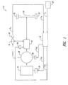
- a secondary power source(s) 12 is used to propel the vehicle.
- the secondary power source 12 is supplied with, and thereby powered by, either (1) an amount of available stored energy in an energy storage device(s) 14, (2) direct input energy generated by an engine(s) 16, or (3) both.
- the determination as to which selection is made depends on the amount of available stored energy stored within the vehicle's 10 energy storage device 14.
- the efficiency level at which the engine 16 operates depends on either (1) the amount of available secondary energy stored in the vehicle's 10 energy storage device 14 or (2) the vehicle's 10 speed and the amount of available secondary energy stored in the vehicle's 10 energy storage device 14.
- the secondary power source 12 for example a pump/motor, is coupled to the primary power source (engine) 16 via a generator 28, for example a pump/motor.
- the generator 28 is used to convert the engine's 16 power into energy compatible for input into the secondary power source (e.g ., electric current or pressurized hydraulic fluid).
- the converted energy is either supplied directly to the secondary power source 12 as direct input energy to power the secondary power source 12 as a motor, and/or supplied to the vehicle's energy storage device 14 and stored for later use (storable energy).
- the type of generator 28 used necessarily depends on the type of energy required to operate the secondary power source 12.
- the generator 28 is an electric generator.
- the generator 28 is a hydraulic pump.
- Generator 28 may also be used to start the engine 16 by acting as a motor using energy from energy storage device 14.
- Fuel energy stored in a vehicle tank (not shown) is used to power the engine 16.
- An engine control device 20, coupled to the engine 16, and in communication with a CPU 18, controls fuel delivery to the engine 16.
- a generator control device 80, coupled to the generator 28, and in communication with CPU 18, controls the speed of engine 16 by varying load. Based on the amount of available stored energy and, optionally, the vehicle speed, the CPU 18 issues a command signal C s1 to the engine control device 20 and a command signal C s2 to the generator control device 80 to operate the engine 16 at a number of preselected power levels.
- an engine 16 can be operated at a preselected power level by operating the engine at a preselected engine speed for a given engine torque value.
- a desired engine torque can be achieved by increasing or decreasing the amount of fuel supplied to an engine 16.
- sensors which detect and monitor engine speed and engine torque.
- Other sensors detect the driver's command to brake the vehicle 10, the driver's command to power the vehicle 10, and monitor vehicle speed.
- the driver's demand to power the vehicle is represented by throttle sensor 22.
- a secondary energy capacity sensor 24 monitors the amount of available stored energy at any given time and generates a signal E s representative of the energy detected.
- the CPU 18 also includes a memory for storing various lookup tables. Methods of monitoring an amount of available stored energy and issuing commands in response to detecting a predetermined amount of available energy in a hybrid vehicle are described in commonly assigned pending U.S. Patent Application Serial No. 10/386,029, filed March 10, 2003 , entitled “METHODS OF OPERATING A PARALLEL HYBRID VEHICLE,” which is incorporated herein by reference.
- a secondary power source control device 26 is coupled to the secondary power source 12 and used to control operation of the secondary power source 12.
- the CPU 18 detects this command and issues a command signal C s3 directing the secondary power source control device 26 to operate the secondary power source 12 as a motor.
- the secondary power source 12 transmits power through a mechanical linkage 30 to the vehicle's 10 wheels 32, and thereby propels the vehicle 10.
- storable energy can also be obtained by capturing the vehicle's kinetic energy during a braking event.
- the CPU 18 directs the secondary power source control device 26 to operate the secondary power source 12 as a generator/pump.
- the vehicle's kinetic energy is then directed to the generator/pump 12, converted into an amount of storable energy, and stored within the vehicle's 10 energy storage device 14.
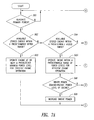
- Figures 2 and 3 show one embodiment for supplying power to the secondary power source 12 in response to a demand to power the vehicle.
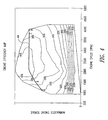
- an amount of available stored energy within the vehicle's 10 energy storage device 14 is monitored and if the available stored energy is at or above a first selected level of available stored energy (depicted as line 37 in Figure 2 , and at step 301 in Figure 3 ), the primary power source 16 does not supply energy to the secondary power source 12. Instead, a portion of the amount of the available stored energy is used to power the secondary power source 12 (step 302).
- the engine is either on and idling, or, alternatively, off (step 303). Determining whether to idle the engine 16 or to turn it off is a design choice, and both options provide certain advantages.
- the engine 16 remains on and is at idle. This minimizes the driver's perception that the engine 16 is no longer generating energy and allows the engine 16 to quickly re-engage when needed. If it is desired to maximize the vehicle's 10 fuel efficiency, the engine 16 is turned off as soon as the available stored energy exceeds the first selected level (e.g ., enters into range 36). However, if the engine 16 is turned off too quickly, there is a risk that customers will perceive that the vehicle is losing power.
- the first selected level e.g ., enters into range 36.
- the engine is turned off when the available stored energy exceeds the first selected level and a command to decelerate the vehicle 10 is issued.
- This provides a more moderate approach that still results in fuel savings during the time the engine 16 is off, but synchronizes the timing of engine shut down with a driver issued command. In this way, the driver is able to logically relate to the sensation that the engine 16 is no longer generating power with a command that is intended to slow or coast the vehicle.
- the engine 16 is operated to generate an amount of primary power (step 304), and the secondary power source is powered with a portion of direct input energy converted from the primary power source (step 305).
- direct input energy alone is used to power the secondary power source, and there is no need to use any of the available stored energy to power the secondary power source.
- available stored energy may also be used, together with the amount of direct input energy, to augment the shortage.
- the amount of available stored energy within the secondary energy storage device 14 is ever drawn to a level below a preselected "safety" level selected to indicate that the available stored energy is at or near depletion, it is preferred to discontinue use of any available stored energy. This is to preserve the life of the secondary energy storage device 14 and minimize performance problems that may result if the secondary energy storage device 14 is operated at too low of an energy level.
- the engine is operated at different power levels depending on whether the available stored energy is within a predetermined upper range (see Figure 2 , range 38), a predetermined middle range (see Figure 2 , range 40), or a predetermined lower range (see Figure 2 , range 42).
- the engine 16 When the engine 16 generates primary power ( Figure 5 , step 501) and the amount of available stored energy is within the predetermined upper range of available energy (e.g ., below line 37 and within range 38 in Figure 2 , and at step 502 in Figure 5 ), the engine is operated at or near a predefined minimum power level for efficient operation of the engine ( Figure 4 , point A; Figure 5 , step 503).
- a first portion of the amount of primary power is converted into an amount of direct input energy and directly supplied to the secondary power source 12. Directly using the first portion of the amount of primary power, as opposed to first storing the first portion of the amount of primary power and then using it, as is done in many conventional series hybrid vehicles, serves to minimize energy transfer losses. As a result, greater energy efficiencies result.
- the engine 16 When the available stored energy is within the predetermined middle range (e.g ., within range 40 in Figure 2 ; and at step 504 in Figure 5 ), the engine 16 is operated at a range that is near a predefined range of power levels for efficient operation of the engine (e.g. , between power levels B and C on torque/curve line 44 in Figure 4 ; and at step 505 in Figure 5 ). In one embodiment, the engine is operated within the predefined range of power levels, at a rate that is inversely proportional to the available stored energy within the predetermined middle range.
- the engine when the available stored energy is at a top most value selected to define the middle range of stored available energy 40, the engine is operated at a power level that is at or near the low end of its range of best power efficiency B, and when the available stored energy is at a bottom most value selected to define the middle range of stored available energy 40, the engine is operated at a power level that is at or near the high end of its range of best power efficiency C. Further, when available stored energy is at a value of equal distance between the top most and the bottom most value of the predetermined second range, the engine is operated at a power level that is near the midpoint of its range of best power efficiency. Operation of the engine at a range of power levels near the range of power levels B and C represents the power level at which the engine is likely to obtain its best operating efficiency. Thus, it is desirable to keep the vehicle operating within this predefined power range as much as possible.
- One strategy for increasing the likelihood that the engine 16 will be operated within the desired predefined power range discussed above is to strive to maintain the amount of available energy within the energy storage device at a level that is within the predetermined middle range 40.
- the engine 16 is operated at or near a predefined maximum power level for efficient operation of the engine ( Figure 4 , point D; Figure 5 , step 507). This causes the engine 16 to produce more power, and increases the likelihood that the amount of power generated by the primary power source and converted into energy will exceed the amount of direct input energy required to power the secondary power source.
- any excess energy is converted into storable energy and stored within the energy storage device. This serves to replenish the amount of available stored energy within the energy storage device and thereby increases the likelihood that the amount of available energy is once again within the desired predetermined middle range 40.
- the engine is preferably sized to be able to meet such potentially necessary sustained vehicle power demands.
- the engine preferably would be of sufficient size to enable the vehicle to ascend a long grade at acceptable speed when fully loaded. Although operation of the vehicle under a condition such as ascending a long grade occurs rarely, the ability to handle such conditions is nevertheless likely required for a vehicle to be commercially acceptable to the public. An engine that could provide at least 60% to 70% of the desired peak acceleration power level for the vehicle would likely be sufficient for this preferred capability.
- This preferred engine size in the present invention differs from prior art series hybrid systems, which instead utilized engines of smaller size.
- first generation secondary energy storage devices such as early generation batteries
- first generation secondary energy storage devices required low charge rates in order to preserve the life of the energy storage device.
- series hybrid vehicles i.e. wherein the charge rate is provided by the engine
- the engine would need to produce power levels sufficiently low to generate the required low charge rates for the energy storage device.
- use of an energy storage device that can charge at faster rates for sustained periods of time will allow efficient use of a larger engine in a series hybrid vehicle.
- an energy storage device that can charge efficiently at faster charge rates, which will therefore enable efficient use of a larger engine size, allowing the engine to run at a high rate of power while the secondary energy source rapidly stores energy, such as would be preferred for conditions where the available stored energy is within the lower range as set forth above.
- An example of an energy storage device with the current capability to sustain such higher charge rates as are preferred for the present invention is the high pressure hydraulic accumulator.
- another preferred embodiment of the present invention also considers the power demanded by the vehicle driver in determining the power level to operate the engine, with additional reference to the logic flow diagram shown in Figure 7 . If the available stored energy is within a predetermined middle range ( Figure 2 , range 40 and Step 504 in Figure 7 ), the engine is still operated within a predetermined range of power levels for efficient operation ( Figure 4 , points within B to C; Step 505 in Figure 7 ), but the power level of the engine responds directionally (the rate of change is a calibration determination) to the power demanded by the vehicle driver (Step 508 of Figure 7 ).
- Step 509 If the driver power demand is greater than the instant power level of the engine, the engine power would be increased (Step 509); if lower, the engine power would be decreased (Step 510). If the available stored energy is within a predetermined lower range ( Figure 2 , range 42, and Step 506 in Figure 7 ), a determination is made whether the driver power demand is greater than the instant power level of the engine (Step 511). If the answer to Step 511 is yes, then the engine operates according to Step 507. If the answer to Step 511 is no, then the engine power level would be reduced (again the rate of change is a calibration determination) in Step 512, but the engine will still be constrained to operate within the power range of Step 505.
- An energy storage device that could efficiently sustain a charge rate matching 20% to 25% of the engine's maximum rated horsepower (or approximately point A in Figure 4 ) would likely be sufficient for this preferred embodiment.
- This embodiment avoids the undesirable noise and feel to the driver of running the engine hard unnecessarily and out of synch with driver power demand. It also provides for more efficient engine use in the recharging of certain secondary energy storage devices.
- the size of the secondary energy storage device will vary according to vehicle needs. Factors influencing the size of an energy storage device include, vehicle size, vehicle weight, vehicle speed, and the size of the primary and secondary power sources. Thus, although the present invention monitors available stored energy and performs certain functions according to the level of available stored energy within an energy storage device 14, the precise levels and ranges of available stored energy chosen as trigger points are a design choice determined by these factors. For example, larger energy storage devices 14 will allow the designer of a hybrid vehicle to use more of the vehicle's 10 available stored energy before reaching the threshold level of available stored energy which triggers the use of primary power, and when primary power is being used more of the operation (time) will occur within the desired predetermined middle range 40.
- multiple engines are used.
- “multiple engines” can also refer to a variable displacement engine with a first engine being the base displacement of the variable displacement engine and “additional engines” being the adding of increased displacement of the variable displacement engine.)
- additional engines e.g., a total of two or more engines may be used.
- Any additional engines may be operated at or near 1) a power level within a predefined range of power levels that is inversely proportional to the amount of available stored energy within the predetermined lower range ( e.g ., within range 42 in Figure 2), or 2 ) a predefined maximum power level for efficient operation of the second engine.
- additional engines may also be desirable when a first engine 16 is operated within the predetermined middle range of available stored energy (e.g ., within range 40 in Figure 2 ) and the power demanded by a user exceeds a predetermined level. This will lessen the likelihood that the amount of available stored energy will drop into the predetermined lower range of available stored energy 42, and increase the likelihood that the first engine 16 will continue to be operated within the predefined range for efficient operation of the engine 16.
- Each of the embodiments described above for determining when to use the primary power source, and how to operate the primary power source when it is used, is based on the amount of available stored energy.
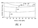
- these determinations are made based on the amount of available stored energy as a function of vehicle speed.
- both available stored energy and vehicle speed are monitored and, if the amount of available stored energy for a given vehicle speed is above a first selected level of available stored energy (depicted by the points comprising line 37a in Figure 6 ), the secondary power source 12 is powered with a portion of the amount of available stored energy and not the primary power source 16. However, if the available stored energy for a given vehicle speed is below the first selected level (again depicted as line 37a in Figure 6 ), then the engine 16 is used to generate primary power.
- how the engine 16 is operated when generating an amount of primary power also depends on the amount of available stored energy at a given vehicle speed.
- the engine is operated at either a minimum power level, a range of power levels, or a maximum power level, but its operation depends on whether the amount of available stored energy at a given vehicle speed is within a predetermined upper, middle or lower range, ranges 38a, 40a, and 42a, respectively. Since it is more likely that a faster moving vehicle will be braked harder or longer and thus result in a greater opportunity to generate more storable energy than a slower moving vehicle, this embodiment is designed to power the secondary power source with more available stored energy at lower speeds than at higher speeds.
- this strategy i.e ., providing more capacity for storing braking energy at higher vehicle speeds
- this strategy furthers the vehicle's opportunity to use of "free" energy and provides yet another means of improving the vehicle's 10 overall energy efficiency.
- a predetermined level of available stored energy is a calibration design choice for the restarting of an engine that was shut off when the available stored energy exceeded a predetermined upper range.
Landscapes
- Engineering & Computer Science (AREA)
- Chemical & Material Sciences (AREA)
- Combustion & Propulsion (AREA)
- Transportation (AREA)
- Mechanical Engineering (AREA)
- Automation & Control Theory (AREA)
- Life Sciences & Earth Sciences (AREA)
- Sustainable Development (AREA)
- Sustainable Energy (AREA)
- Power Engineering (AREA)
- Control Of Vehicle Engines Or Engines For Specific Uses (AREA)
- Hybrid Electric Vehicles (AREA)
- Electric Propulsion And Braking For Vehicles (AREA)
- Output Control And Ontrol Of Special Type Engine (AREA)
- Control Of Driving Devices And Active Controlling Of Vehicle (AREA)
Applications Claiming Priority (2)
| Application Number | Priority Date | Filing Date | Title |
|---|---|---|---|
| US10/672,732 US6876098B1 (en) | 2003-09-25 | 2003-09-25 | Methods of operating a series hybrid vehicle |
| PCT/US2004/028729 WO2005032875A1 (en) | 2003-09-25 | 2004-09-03 | Methods of operating a series hybrid vehicle |
Publications (2)
| Publication Number | Publication Date |
|---|---|
| EP1667864A1 EP1667864A1 (en) | 2006-06-14 |
| EP1667864B1 true EP1667864B1 (en) | 2011-01-19 |
Family
ID=34376452
Family Applications (1)
| Application Number | Title | Priority Date | Filing Date |
|---|---|---|---|
| EP04783088A Expired - Lifetime EP1667864B1 (en) | 2003-09-25 | 2004-09-03 | Methods of operating a series hybrid vehicle |
Country Status (10)
| Country | Link |
|---|---|
| US (4) | US6876098B1 (enExample) |
| EP (1) | EP1667864B1 (enExample) |
| JP (3) | JP2007510566A (enExample) |
| KR (2) | KR20120039721A (enExample) |
| CN (1) | CN1856413B (enExample) |
| AU (1) | AU2004278296B2 (enExample) |
| CA (1) | CA2538775C (enExample) |
| DE (1) | DE602004031131D1 (enExample) |
| MX (1) | MXPA06003414A (enExample) |
| WO (1) | WO2005032875A1 (enExample) |
Families Citing this family (105)
| Publication number | Priority date | Publication date | Assignee | Title |
|---|---|---|---|---|
| US8177009B2 (en) | 2000-01-10 | 2012-05-15 | The United States Of America As Represented By The Administrator Of The U.S. Environmental Protection Agency | Independent displacement opposing pump/motors and method of operation |
| US20040204797A1 (en) * | 2003-01-16 | 2004-10-14 | Vickers Mark F. | Method and apparatus for regulating power in a vehicle |
| DE10318738A1 (de) * | 2003-04-25 | 2004-11-11 | Daimlerchrysler Ag | Steuerung eines Elektromotors |
| US7073615B2 (en) * | 2003-09-19 | 2006-07-11 | Ford Global Technologies, Llc. | System and method for operating an electric motor by limiting performance |
| US7232401B2 (en) * | 2004-01-28 | 2007-06-19 | General Motors Corporation | Method of compensating torque at cylinder switching on a DOD engine with electric parallel hybrid |
| US20050228553A1 (en) * | 2004-03-30 | 2005-10-13 | Williams International Co., L.L.C. | Hybrid Electric Vehicle Energy Management System |
| FR2882699B1 (fr) * | 2005-03-01 | 2008-10-31 | Peugeot Citroen Automobiles Sa | Procede de decollage d'un vehicule en pente montante et ou lourdement charge |
| US8136615B2 (en) * | 2005-09-01 | 2012-03-20 | Avl List Gmbh | Method for operating an internal combustion engine |
| US20070087239A1 (en) * | 2005-10-18 | 2007-04-19 | General Hydrogen Corporation | Fuel cell fluid management system |
| US20070087241A1 (en) * | 2005-10-18 | 2007-04-19 | General Hydrogen Corporation | Fuel cell power pack |
| US20070087232A1 (en) * | 2005-10-18 | 2007-04-19 | Robin Curtis M | Capacitor hybrid fuel cell power generator |
| US7605493B1 (en) * | 2005-11-09 | 2009-10-20 | Joseph P. Boudreaux | Electrically powered vehicle engine |
| US11254211B2 (en) | 2005-11-17 | 2022-02-22 | Invently Automotive Inc. | Electric vehicle power management system |
| US11186173B2 (en) | 2005-11-17 | 2021-11-30 | Invently Automotive Inc. | Electric vehicle power management system |
| US11247564B2 (en) | 2005-11-17 | 2022-02-15 | Invently Automotive Inc. | Electric vehicle power management system |
| US11370302B2 (en) | 2005-11-17 | 2022-06-28 | Invently Automotive Inc. | Electric vehicle power management system |
| US11345236B2 (en) | 2005-11-17 | 2022-05-31 | Invently Automotive Inc. | Electric vehicle power management system |
| US10882399B2 (en) | 2005-11-17 | 2021-01-05 | Invently Automotive Inc. | Electric vehicle power management system |
| US11230190B2 (en) | 2005-11-17 | 2022-01-25 | Invently Automotive Inc. | Electric vehicle power management system |
| US11214144B2 (en) | 2005-11-17 | 2022-01-04 | Invently Automotive Inc. | Electric vehicle power management system |
| US11390165B2 (en) | 2005-11-17 | 2022-07-19 | Invently Automotive Inc. | Electric vehicle power management system |
| US11279233B2 (en) | 2005-11-17 | 2022-03-22 | Invently Automotive Inc. | Electric vehicle power management system |
| US11180025B2 (en) | 2005-11-17 | 2021-11-23 | Invently Automotive Inc. | Electric vehicle power management system |
| US11267338B2 (en) | 2005-11-17 | 2022-03-08 | Invently Automotive Inc. | Electric vehicle power management system |
| US7206687B1 (en) * | 2006-04-06 | 2007-04-17 | General Motors Corporation | Method for controlling a hybrid electric vehicle |
| EP2025904B1 (en) * | 2006-06-07 | 2016-06-01 | Toyota Jidosha Kabushiki Kaisha | Hybrid vehicle |
| US8485291B2 (en) * | 2006-08-22 | 2013-07-16 | John William O'Neill | Self frequency ramping alternating current wheel motor system for hybrid vehicles |
| SE0601773L (sv) * | 2006-08-29 | 2008-03-01 | Cargine Engineering Ab | Fordonsdrivsystem |
| US8356985B2 (en) | 2006-09-29 | 2013-01-22 | The United States Of America, As Represented By The Administrator Of The U.S. Environmental Protection Agency | Safe over-center pump/motor |
| US7831343B2 (en) * | 2006-11-03 | 2010-11-09 | Gm Global Technology Operations, Inc. | Efficiency optimized hybrid operation strategy |
| US7573145B2 (en) * | 2006-11-16 | 2009-08-11 | Cummins Power Generation Ip, Inc. | Electric power generation system controlled to reduce perception of operational changes |
| US7832198B2 (en) * | 2006-12-05 | 2010-11-16 | Ford Global Technologies, Llc | System and method for controlling an operating temperature of a catalyst of a vehicle exhaust system |
| US8556009B2 (en) * | 2006-12-19 | 2013-10-15 | Bradley Wayne Bartilson | Safe, super-efficient, four-wheeled vehicle employing large diameter wheels with continuous-radius tires, with leaning option |
| US7808214B2 (en) * | 2006-12-19 | 2010-10-05 | Bradley Wayne Bartilson | Short-cycling serial hybrid drivetrain with high power density storage |
| US7642755B2 (en) * | 2006-12-19 | 2010-01-05 | Bradley Wayne Bartilson | Method and apparatus to maximize stored energy in UltraCapacitor Systems |
| US8100216B2 (en) * | 2006-12-19 | 2012-01-24 | Bradley Wayne Bartilson | Hybrid drivetrain with waste heat energy conversion into electricity |
| JP5145724B2 (ja) * | 2007-02-14 | 2013-02-20 | トヨタ自動車株式会社 | 電力供給システム |
| KR101247282B1 (ko) * | 2007-02-26 | 2013-03-25 | 삼성테크윈 주식회사 | 직렬형 하이브리드 동력장치의 제어장치 |
| JP4321619B2 (ja) * | 2007-03-30 | 2009-08-26 | トヨタ自動車株式会社 | 車両およびその制御方法 |
| US7849944B2 (en) * | 2007-06-12 | 2010-12-14 | Ut-Battelle, Llc | Self-learning control system for plug-in hybrid vehicles |
| US8448731B2 (en) * | 2007-11-05 | 2013-05-28 | GM Global Technology Operations LLC | Method and apparatus for determination of fast actuating engine torque for a hybrid powertrain system |
| US20110064706A1 (en) * | 2008-01-11 | 2011-03-17 | U.S. Nutraceuticals, Llc D/B/A Valensa International | Method of preventing, controlling and ameliorating urinary tract infections and supporting digestive health by using a synergistic cranberry derivative, a d-mannose composition and a proprietary probiotic blend |
| US20090242301A1 (en) * | 2008-04-01 | 2009-10-01 | Mcclanahan Robert F | Efficient Vehicle Power Systems |
| US9707835B2 (en) | 2008-04-01 | 2017-07-18 | 3B Technologies Ii | Efficient vehicle power systems |
| WO2009157891A1 (en) * | 2008-06-23 | 2009-12-30 | Bayerische Motoren Werke Aktiengesellschaft | Reduction of power losses for vehicle drive trains with recuperation devices |
| US8464690B2 (en) | 2008-07-11 | 2013-06-18 | Tula Technology, Inc. | Hybrid vehicle with cylinder deactivation |
| US8892330B2 (en) | 2011-10-17 | 2014-11-18 | Tula Technology, Inc. | Hybrid vehicle with cylinder deactivation |
| TWI413593B (zh) * | 2008-11-28 | 2013-11-01 | Ind Tech Res Inst | 一種混合動力系統的串並聯耦合控制方法與系統 |
| JP5700225B2 (ja) * | 2009-06-03 | 2015-04-15 | イートン コーポレーションEaton Corporation | 磁気ラッチングバルブ付流体装置 |
| KR101112136B1 (ko) * | 2009-07-29 | 2012-02-22 | 볼보 컨스트럭션 이큅먼트 에이비 | 하이브리드식 건설기계의 제어시스템 및 방법 |
| US8760115B2 (en) * | 2009-08-20 | 2014-06-24 | GM Global Technology Operations LLC | Method for charging a plug-in electric vehicle |
| WO2011024772A1 (ja) * | 2009-08-26 | 2011-03-03 | 富士通テン株式会社 | エンジン制御装置、車両、及び、エンジン制御方法 |
| US20110056192A1 (en) * | 2009-09-10 | 2011-03-10 | Robert Weber | Technique for controlling pumps in a hydraulic system |
| US20110056194A1 (en) * | 2009-09-10 | 2011-03-10 | Bucyrus International, Inc. | Hydraulic system for heavy equipment |
| US20110083918A1 (en) * | 2009-09-15 | 2011-04-14 | Kpit Cummins Infosystems Ltd. | Hybrid drive system for vehicle having engine as prime mover |
| WO2011039769A2 (en) * | 2009-09-15 | 2011-04-07 | Kpit Cummins Infosystems Ltd. | Hybrid drive system with reduced power requirement for vehicle |
| BR112012005361A2 (pt) | 2009-09-15 | 2023-11-21 | Kpit Cummins Infosystems Ltd | Método de conversão de um veículo convencional para híbrido |
| JP5926182B2 (ja) | 2009-09-15 | 2016-05-25 | ケーピーアイティ テクノロジーズ リミテッド | ユーザ入力に基づくハイブリッド車のモータ補助 |
| WO2011033528A2 (en) | 2009-09-15 | 2011-03-24 | Kpit Cummins Infosystems Limited | Motor assistance for a hybrid vehicle |
| US9227626B2 (en) * | 2009-09-15 | 2016-01-05 | Kpit Technologies Limited | Motor assistance for a hybrid vehicle based on predicted driving range |
| CN102781713B (zh) * | 2010-01-21 | 2015-12-02 | 电子能量发动机系统有限责任公司 | 碳氢燃料电系列混合推进系统 |
| US8362629B2 (en) * | 2010-03-23 | 2013-01-29 | Bucyrus International Inc. | Energy management system for heavy equipment |
| RU2012142349A (ru) * | 2010-04-05 | 2014-04-10 | Хонда Мотор Ко., Лтд. | Модуль управления для гибридного транспортного средства |
| US8509974B2 (en) * | 2010-08-23 | 2013-08-13 | Cummins Inc. | Hybrid power train rate control |
| US8403101B2 (en) * | 2010-09-15 | 2013-03-26 | Deere & Company | User interface for energy sources on a hybrid vehicle |
| US8405355B2 (en) * | 2010-09-23 | 2013-03-26 | GM Global Technology Operations LLC | Energy storage system energy capacity and capability monitor |
| US8626403B2 (en) | 2010-10-06 | 2014-01-07 | Caterpillar Global Mining Llc | Energy management and storage system |
| US8606451B2 (en) | 2010-10-06 | 2013-12-10 | Caterpillar Global Mining Llc | Energy system for heavy equipment |
| US8718845B2 (en) | 2010-10-06 | 2014-05-06 | Caterpillar Global Mining Llc | Energy management system for heavy equipment |
| KR101029753B1 (ko) * | 2010-10-21 | 2011-04-21 | 주식회사 피플에코 | 스털링엔진을 이용한 하이브리드자동차 및 그 제어방법 |
| JP2012121555A (ja) * | 2010-11-16 | 2012-06-28 | Honda Motor Co Ltd | ハイブリッド車両の制御装置およびハイブリッド車両の制御方法 |
| JP5779891B2 (ja) * | 2011-01-21 | 2015-09-16 | トヨタ自動車株式会社 | レンジエクステンダ |
| KR101237317B1 (ko) * | 2011-03-11 | 2013-02-28 | 국방과학연구소 | 4륜구동 하이브리드 차량의 추진 장치 및 방법 |
| AT512023B1 (de) | 2011-10-13 | 2015-06-15 | Avl List Gmbh | Verfahren zum betreiben eines stromerzeugungsaggregates |
| US8880258B2 (en) | 2011-10-17 | 2014-11-04 | Tula Technology, Inc. | Hybrid powertrain control |
| CN104024025A (zh) | 2011-10-18 | 2014-09-03 | Amt有限公司 | 混合动力集成管理系统 |
| BR112014010959B1 (pt) * | 2011-11-08 | 2020-10-20 | Volvo Lastvagnar Ab | método e disposição em um veículo híbrido |
| CN104039682B (zh) | 2012-01-09 | 2017-04-12 | 伊顿公司 | 用于使用单一输入获得全范围升降速度的方法 |
| US9580062B2 (en) * | 2012-01-10 | 2017-02-28 | Ford Global Technologies, Llc | Method for increasing fuel economy of plug-in hybrid electric vehicles |
| US9039568B2 (en) * | 2012-05-04 | 2015-05-26 | Ford Global Technologies, Llc | Methods and systems for extending regenerative braking |
| WO2014034710A1 (ja) * | 2012-08-29 | 2014-03-06 | 株式会社ホンダアクセス | 車両に設けられたバッテリを監視するシステム |
| US8694225B2 (en) * | 2012-09-07 | 2014-04-08 | Ford Global Technologies, Llc | Utilization of vehicle presence systems for powertrain response readiness and conserving energy |
| US9190852B2 (en) | 2012-09-21 | 2015-11-17 | Caterpillar Global Mining Llc | Systems and methods for stabilizing power rate of change within generator based applications |
| US9174525B2 (en) | 2013-02-25 | 2015-11-03 | Fairfield Manufacturing Company, Inc. | Hybrid electric vehicle |
| CN103231661A (zh) * | 2013-04-17 | 2013-08-07 | 孔令斌 | 一种斯特林发电机驱动的电动汽车 |
| JP6182770B2 (ja) * | 2013-08-30 | 2017-08-23 | 日立オートモティブシステムズ株式会社 | 電動車両制御システム |
| KR101558359B1 (ko) * | 2013-12-18 | 2015-10-08 | 현대자동차 주식회사 | 하이브리드 차량의 토크 모니터링 방법 |
| KR102445784B1 (ko) | 2014-05-06 | 2022-09-21 | 단포스 파워 솔루션스 Ii 테크놀로지 에이/에스 | 유체정역학 옵션을 구비하는 유압 하이브리드 추진 회로 및 작동 방법 |
| JP6806409B2 (ja) | 2014-10-27 | 2021-01-06 | イートン コーポレーションEaton Corporation | 静圧オプションを有する油圧ハイブリッド推進回路とその操作方法 |
| US10060368B2 (en) | 2015-01-12 | 2018-08-28 | Tula Technology, Inc. | Engine torque smoothing |
| US10344692B2 (en) | 2015-01-12 | 2019-07-09 | Tula Technology, Inc. | Adaptive torque mitigation by micro-hybrid system |
| JP6524546B2 (ja) | 2015-01-12 | 2019-06-05 | トゥラ テクノロジー インコーポレイテッドTula Technology,Inc. | スキップファイアエンジン制御システムにおける騒音、振動およびハーシュネスの低減 |
| US10578037B2 (en) | 2015-01-12 | 2020-03-03 | Tula Technology, Inc. | Adaptive torque mitigation by micro-hybrid system |
| US10196995B2 (en) | 2015-01-12 | 2019-02-05 | Tula Technology, Inc. | Engine torque smoothing |
| TWI599715B (zh) * | 2015-10-05 | 2017-09-21 | jia-wen Ruan | Engine waste heat power recovery system and method |
| JP6419063B2 (ja) * | 2015-12-24 | 2018-11-07 | 日立建機株式会社 | ハイブリッド式作業機械 |
| JP6447838B2 (ja) * | 2016-11-21 | 2019-01-09 | トヨタ自動車株式会社 | 燃料電池車両 |
| US10954877B2 (en) | 2017-03-13 | 2021-03-23 | Tula Technology, Inc. | Adaptive torque mitigation by micro-hybrid system |
| WO2019084527A1 (en) | 2017-10-27 | 2019-05-02 | Quantum Industrial Development Corporation | SERIES TYPE HYBRID ELECTRIC KINEMATIC CHAIN FOR EXTERNAL COMBUSTION ENGINE |
| DE102018206827A1 (de) * | 2018-05-03 | 2019-11-07 | Ford Global Technologies, Llc | Batteriesystem und elektrisch antreibbares Kraftfahrzeug |
| KR102518656B1 (ko) * | 2018-05-23 | 2023-04-06 | 현대자동차주식회사 | 친환경 차량의 토크 분담식 관성주행제어방법 |
| US11515741B2 (en) | 2020-08-28 | 2022-11-29 | Toyota Motor North America, Inc. | Wireless energy transfer to transport based on route data |
| US11865939B2 (en) | 2020-08-28 | 2024-01-09 | Toyota Motor North America, Inc. | Power allocation to transports |
| US11555461B2 (en) | 2020-10-20 | 2023-01-17 | Tula Technology, Inc. | Noise, vibration and harshness reduction in a skip fire engine control system |
| CN113236431B (zh) * | 2021-06-21 | 2023-05-30 | 上海三一重机股份有限公司 | 一种工程机械节能控制方法、装置及工程机械 |
Family Cites Families (180)
| Publication number | Priority date | Publication date | Assignee | Title |
|---|---|---|---|---|
| US52677A (en) * | 1866-02-20 | Improvement in tube-gear for oscillating engines | ||
| US65165A (en) * | 1867-05-28 | Francisco | ||
| US55411A (en) * | 1866-06-05 | Improvement in machinery for making wire sieves | ||
| JPS4916112A (enExample) * | 1972-06-12 | 1974-02-13 | ||
| US4351405A (en) | 1978-10-12 | 1982-09-28 | Hybricon Inc. | Hybrid car with electric and heat engine |
| JPS55127221A (en) | 1979-03-20 | 1980-10-01 | Daihatsu Motor Co Ltd | Driving system of vehicle |
| US4547678A (en) | 1980-01-11 | 1985-10-15 | Califone International, Inc. | Hybrid electric vehicle control methods and devices |
| US4407132A (en) | 1980-02-20 | 1983-10-04 | Daihatsu Motor Co., Ltd. | Control apparatus and method for engine/electric hybrid vehicle |
| US4363999A (en) | 1980-07-14 | 1982-12-14 | Preikschat F K | Electric propulsion and braking system for automotive vehicles |
| DE3112629A1 (de) * | 1981-03-30 | 1982-10-07 | Volkswagenwerk Ag, 3180 Wolfsburg | "verfahren zum betrieb eines hybridfahrzeuges" |
| US4493221A (en) * | 1983-01-12 | 1985-01-15 | The Gates Rubber Company | Variable speed, belt driven transmission system, speed sensing driver pulley and method |
| DE3526620A1 (de) * | 1984-08-16 | 1986-02-27 | Robert Bosch Gmbh, 7000 Stuttgart | Regelvorrichtung in einem kraftfahrzeug |
| US5176213A (en) | 1987-12-09 | 1993-01-05 | Aisin Aw Co., Ltd. | Driving force distribution system for hybrid vehicles |
| US4901695A (en) * | 1988-10-20 | 1990-02-20 | Delco Electronics Corporation | Dual slope engine drive-by-wire drive circuit |
| US4908553A (en) | 1988-12-20 | 1990-03-13 | Eaton Corporation | Magnetic regenerative braking system |
| US5046177A (en) * | 1990-06-01 | 1991-09-03 | General Motors Corporation | Engine-CVT performance mode system |
| US5081365A (en) | 1990-06-06 | 1992-01-14 | Field Bruce F | Electric hybrid vehicle and method of controlling it |
| SE9100612L (sv) | 1991-02-06 | 1992-08-07 | Lauzun Corp | Hybriddrivsystem foer motorfordon |
| JP3044880B2 (ja) * | 1991-11-22 | 2000-05-22 | トヨタ自動車株式会社 | シリーズハイブリッド車の駆動制御装置 |
| JPH05199609A (ja) * | 1992-01-20 | 1993-08-06 | Toyota Motor Corp | ハイブリッド車の駆動制御装置 |
| US5327987A (en) | 1992-04-02 | 1994-07-12 | Abdelmalek Fawzy T | High efficiency hybrid car with gasoline engine, and electric battery powered motor |
| JP2797863B2 (ja) * | 1992-10-21 | 1998-09-17 | 日産自動車株式会社 | ハイブリッド型電気自動車 |
| US5291960A (en) | 1992-11-30 | 1994-03-08 | Ford Motor Company | Hybrid electric vehicle regenerative braking energy recovery system |
| US5450324A (en) | 1993-01-07 | 1995-09-12 | Ford Motor Company | Electric vehicle regenerative antiskid braking and traction control system |
| US5358317A (en) | 1993-01-07 | 1994-10-25 | Ford Motor Company | Fuzzy logic electric vehicle regenerative antiskid braking and traction control system |
| US5412251A (en) * | 1993-01-14 | 1995-05-02 | Toyota Jidosha Kabushiki Kaisha | Controller of an engine driving generator for an electric vehicle |
| US5437554A (en) * | 1993-02-05 | 1995-08-01 | National Computer Systems, Inc. | System for providing performance feedback to test resolvers |
| US5376869A (en) | 1993-02-11 | 1994-12-27 | General Electric Company | Electric vehicle drive train with rollback detection and compensation |
| US5403244A (en) | 1993-04-15 | 1995-04-04 | General Electric Company | Electric vehicle drive train with direct coupling transmission |
| US5359308A (en) | 1993-10-27 | 1994-10-25 | Ael Defense Corp. | Vehicle energy management system using superconducting magnetic energy storage |
| JP3013694B2 (ja) * | 1994-04-08 | 2000-02-28 | 三菱自動車工業株式会社 | ハイブリッド電気自動車における発電系制御装置 |
| JP2937008B2 (ja) * | 1994-04-13 | 1999-08-23 | 三菱自動車工業株式会社 | ハイブリッド車用エンジンの制御装置 |
| DE4415073A1 (de) | 1994-04-29 | 1995-11-02 | Fev Motorentech Gmbh & Co Kg | Hubkolbenmotor mit direkter Kraftstoffeinspritzeinrichtung und Funkenzündung, insbesondere für den Betrieb mit Alkoholkraftstoff |
| US5568023A (en) | 1994-05-18 | 1996-10-22 | Grayer; William | Electric power train control |
| JP3094790B2 (ja) | 1994-05-20 | 2000-10-03 | トヨタ自動車株式会社 | ハイブリッド型電気自動車 |
| US5495912A (en) | 1994-06-03 | 1996-03-05 | The United States Of America As Represented By The Administrator Of The U.S. Environmental Protection Agency | Hybrid powertrain vehicle |
| JP3047741B2 (ja) * | 1994-08-05 | 2000-06-05 | トヨタ自動車株式会社 | シリーズハイブリッド車における発電制御方法 |
| JP2587202B2 (ja) | 1994-08-22 | 1997-03-05 | 本田技研工業株式会社 | ハイブリッド車両の発電制御装置 |
| JP2738819B2 (ja) | 1994-08-22 | 1998-04-08 | 本田技研工業株式会社 | ハイブリッド車両の発電制御装置 |
| JP2790779B2 (ja) | 1994-08-22 | 1998-08-27 | 本田技研工業株式会社 | ハイブリッド車両の発電制御装置 |
| JP3050054B2 (ja) | 1994-09-01 | 2000-06-05 | トヨタ自動車株式会社 | 発電制御方法 |
| JP3336777B2 (ja) | 1994-10-25 | 2002-10-21 | 株式会社エクォス・リサーチ | ハイブリッド車両及びハイブリッド車両の制御方法 |
| JP2783983B2 (ja) | 1995-02-03 | 1998-08-06 | 株式会社エクォス・リサーチ | ハイブリッド型車両 |
| JPH08289407A (ja) * | 1995-02-13 | 1996-11-01 | Nippon Soken Inc | ハイブリッド車の発電制御装置 |
| US5659240A (en) | 1995-02-16 | 1997-08-19 | General Electric Company | Intelligent battery charger for electric drive system batteries |
| US5562079A (en) | 1995-02-23 | 1996-10-08 | The United States Of America As Represented By The Administrator Of The U.S. Environmental Protection Agency | Low-temperature, near-adiabatic engine |
| US5589743A (en) | 1995-03-03 | 1996-12-31 | General Electric Company | Integrated cranking inverter and boost converter for a series hybrid drive system |
| JPH08336205A (ja) | 1995-04-07 | 1996-12-17 | Nippon Soken Inc | ハイブリッド車両のバッテリ充電装置 |
| JP3534271B2 (ja) | 1995-04-20 | 2004-06-07 | 株式会社エクォス・リサーチ | ハイブリッド車両 |
| US5579640A (en) | 1995-04-27 | 1996-12-03 | The United States Of America As Represented By The Administrator Of The Environmental Protection Agency | Accumulator engine |
| US5549087A (en) | 1995-04-27 | 1996-08-27 | The United States Of America As Represented By The Administrator Of The U.S. Environmental Protection Agency | Combined cycle engine |
| JP3087884B2 (ja) | 1995-04-28 | 2000-09-11 | 本田技研工業株式会社 | ハイブリッド車の発電制御装置 |
| JP2893262B2 (ja) | 1995-04-28 | 1999-05-17 | 株式会社エクォス・リサーチ | ハイブリッド車両 |
| US6054844A (en) | 1998-04-21 | 2000-04-25 | The Regents Of The University Of California | Control method and apparatus for internal combustion engine electric hybrid vehicles |
| US5842534A (en) | 1995-05-31 | 1998-12-01 | Frank; Andrew A. | Charge depletion control method and apparatus for hybrid powered vehicles |
| US6116363A (en) | 1995-05-31 | 2000-09-12 | Frank Transportation Technology, Llc | Fuel consumption control for charge depletion hybrid electric vehicles |
| JP3209046B2 (ja) | 1995-06-20 | 2001-09-17 | トヨタ自動車株式会社 | ハイブリッド車 |
| JPH0937407A (ja) | 1995-07-18 | 1997-02-07 | Toyota Motor Corp | 回生制動制御装置 |
| JP3171079B2 (ja) | 1995-07-24 | 2001-05-28 | トヨタ自動車株式会社 | 車両用駆動制御装置 |
| JPH0998515A (ja) | 1995-07-25 | 1997-04-08 | Nippon Soken Inc | ハイブリッド車のエンジン制御装置 |
| US5881559A (en) | 1995-07-28 | 1999-03-16 | Isuzu Ceramics Research Institute Co., Ltd. | Hybrid electric vehicle |
| JPH0970105A (ja) | 1995-08-31 | 1997-03-11 | Isuzu Ceramics Kenkyusho:Kk | ハイブリッド車両 |
| JP3167890B2 (ja) * | 1995-08-11 | 2001-05-21 | 本田技研工業株式会社 | ハイブリッド車両の車載発電装置の制御装置 |
| US5511859A (en) | 1995-08-25 | 1996-04-30 | General Motors Corporation | Regenerative and friction brake blend control |
| US5609131A (en) | 1995-10-11 | 1997-03-11 | The United States Of America As Represented By The Administrator Of The U.S. Environmental Protection Agency | Multi-stage combustion engine |
| US5887674A (en) | 1995-10-11 | 1999-03-30 | The United States Of America As Represented By The Administrator Of The U.S. Environmental Protection Agency | Continuously smooth transmission |
| US5611300A (en) | 1995-10-11 | 1997-03-18 | The United States Of America As Represented By The Administrator Of The Environmental Protection Agency | Floating piston, piston-valve engine |
| JP3216501B2 (ja) | 1995-10-13 | 2001-10-09 | トヨタ自動車株式会社 | ハイブリッド駆動装置 |
| JP3094872B2 (ja) | 1995-10-20 | 2000-10-03 | トヨタ自動車株式会社 | ハイブリッド車用制御装置 |
| JP3610687B2 (ja) | 1995-12-12 | 2005-01-19 | トヨタ自動車株式会社 | 内燃機関の始動制御装置およびその制御方法 |
| US5713426A (en) * | 1996-03-19 | 1998-02-03 | Jeol Ltd. | Hybrid vehicle |
| JP3256657B2 (ja) | 1996-04-10 | 2002-02-12 | 本田技研工業株式会社 | ハイブリッド車両の制御装置 |
| JP3520668B2 (ja) | 1996-06-11 | 2004-04-19 | トヨタ自動車株式会社 | ハイブリッド車両の制御装置 |
| JPH102239A (ja) | 1996-06-14 | 1998-01-06 | Toyota Motor Corp | ハイブリッド型車両のエンジン制御装置 |
| JP3288928B2 (ja) | 1996-06-14 | 2002-06-04 | 日野自動車株式会社 | 車載電池の制御装置 |
| JP3371691B2 (ja) * | 1996-06-25 | 2003-01-27 | 日産自動車株式会社 | ハイブリッド車の発電制御装置 |
| CA2182630C (en) | 1996-08-02 | 2003-02-11 | Piotr Drozdz | A control system for a hybrid vehicle |
| DE19633194C2 (de) | 1996-08-17 | 1998-09-17 | Daimler Benz Ag | Serieller Hybridantrieb, insbesondere für ein Kraftfahrzeug |
| JP3304777B2 (ja) * | 1996-08-22 | 2002-07-22 | トヨタ自動車株式会社 | 電動車両 |
| US5707115A (en) | 1996-10-07 | 1998-01-13 | General Motors Corporation | Regenerative braking method |
| DE19704153C2 (de) | 1997-02-04 | 2000-10-19 | Isad Electronic Sys Gmbh & Co | Antriebssystem, insbesondere für ein Kraftfahrzeug und Verfahren zum Entgegenwirken einer Änderung der Leerlaufdrehzahl in einem Antriebssystem |
| JPH1132059A (ja) * | 1997-04-09 | 1999-02-02 | Alcatel Alsthom Co General Electricite | 高速インターネットアクセス |
| JP2982746B2 (ja) | 1997-06-06 | 1999-11-29 | トヨタ自動車株式会社 | ハイブリッド車両の内燃機関制御装置 |
| GB9714132D0 (en) | 1997-07-05 | 1997-09-10 | Rover Group | Catalyst temperature control in hybrid vehicles |
| JP3767103B2 (ja) * | 1997-07-16 | 2006-04-19 | 日産自動車株式会社 | 電気自動車の制御装置 |
| DE69834588T2 (de) | 1997-09-15 | 2006-09-07 | Honda Giken Kogyo K.K. | Vorrichtung zur Steuerung eines Hybridfahrzeuges |
| JP3379439B2 (ja) | 1997-09-17 | 2003-02-24 | トヨタ自動車株式会社 | 内燃機関の始動制御装置 |
| US6367570B1 (en) | 1997-10-17 | 2002-04-09 | Electromotive Inc. | Hybrid electric vehicle with electric motor providing strategic power assist to load balance internal combustion engine |
| JP3454116B2 (ja) * | 1997-11-10 | 2003-10-06 | トヨタ自動車株式会社 | 車両用駆動装置 |
| JP3257486B2 (ja) | 1997-11-12 | 2002-02-18 | トヨタ自動車株式会社 | 動力出力装置および内燃機関制御装置 |
| JP3456624B2 (ja) * | 1997-11-28 | 2003-10-14 | 本田技研工業株式会社 | ハイブリッド車両の制御装置 |
| JP3341659B2 (ja) | 1997-12-05 | 2002-11-05 | 日産自動車株式会社 | ハイブリッド車の制御装置 |
| JP3374734B2 (ja) | 1997-12-09 | 2003-02-10 | トヨタ自動車株式会社 | ハイブリット車の内燃機関制御装置 |
| JP3381613B2 (ja) | 1998-03-20 | 2003-03-04 | 日産自動車株式会社 | ハイブリッド車両の駆動制御装置 |
| JPH11270668A (ja) | 1998-03-20 | 1999-10-05 | Nissan Motor Co Ltd | ハイブリッド車両の駆動制御装置 |
| JP3336951B2 (ja) | 1998-04-28 | 2002-10-21 | 株式会社日立製作所 | 自動車の動力伝達装置 |
| JP3172490B2 (ja) | 1998-05-18 | 2001-06-04 | 株式会社日立製作所 | ハイブリッド車 |
| US6269290B1 (en) | 1998-07-01 | 2001-07-31 | Denso Corporation | Engine-motor hybrid vehicle control apparatus and method having engine performance Lessening compensation |
| JP3003675B2 (ja) | 1998-07-07 | 2000-01-31 | 株式会社デンソー | ハイブリッド電気自動車の制御装置 |
| US6232733B1 (en) | 1998-07-28 | 2001-05-15 | Denso Corporation | Engine-motor hybrid vehicle control apparatus and method having power transmission device operation compensation function |
| JP2000045816A (ja) * | 1998-07-29 | 2000-02-15 | Mazda Motor Corp | ハイブリッド自動車 |
| US6202416B1 (en) | 1998-08-13 | 2001-03-20 | The United States Of America As Represented By The Administrator Of The U.S. Environmental Protection Agency | Dual-cylinder expander engine and combustion method with two expansion strokes per cycle |
| JP3449239B2 (ja) | 1998-09-22 | 2003-09-22 | 日産自動車株式会社 | ハイブリッド車両の制御装置 |
| JP3927325B2 (ja) | 1998-10-21 | 2007-06-06 | トヨタ自動車株式会社 | 車両の制御装置 |
| US6203468B1 (en) | 1998-11-18 | 2001-03-20 | Fuji Jukogyo Kabushiki Kaisha | Control device for hybrid vehicle and method thereof |
| JP3385986B2 (ja) | 1998-12-18 | 2003-03-10 | 本田技研工業株式会社 | シリーズハイブリッド車の出力制御装置 |
| JP3598491B2 (ja) | 1998-12-25 | 2004-12-08 | 本田技研工業株式会社 | ブレーキ液圧保持装置 |
| JP4085500B2 (ja) | 1999-01-29 | 2008-05-14 | 株式会社エクォス・リサーチ | 車両状況把握装置、エージェント装置、および、車両制御装置 |
| JP3536703B2 (ja) | 1999-02-09 | 2004-06-14 | 株式会社日立製作所 | ハイブリッド車両の制御方法、ハイブリッド車両の制御装置およびハイブリッド車両 |
| JP3536704B2 (ja) | 1999-02-17 | 2004-06-14 | 日産自動車株式会社 | 車両の駆動力制御装置 |
| JP3488654B2 (ja) | 1999-03-09 | 2004-01-19 | 本田技研工業株式会社 | ハイブリッド車両のエンジン制御装置 |
| JP2000257462A (ja) * | 1999-03-09 | 2000-09-19 | Honda Motor Co Ltd | ハイブリッド車両のエンジン制御装置 |
| JP3644298B2 (ja) | 1999-03-31 | 2005-04-27 | スズキ株式会社 | モータ駆動制御装置 |
| JP3575320B2 (ja) | 1999-03-31 | 2004-10-13 | スズキ株式会社 | 車両のモータ駆動制御装置 |
| JP3937728B2 (ja) | 1999-05-12 | 2007-06-27 | 株式会社日立製作所 | 車両の走行制御装置および車両 |
| US6170524B1 (en) | 1999-05-21 | 2001-01-09 | The United States Of America As Represented By The Administrator Of The Environmental Protection Agency | Fast valve and actuator |
| JP2001193661A (ja) | 1999-06-08 | 2001-07-17 | Denso Corp | 作動油供給システムおよびその制御方法 |
| JP3546401B2 (ja) | 1999-08-06 | 2004-07-28 | 本田技研工業株式会社 | 車両の駆動力制御装置 |
| JP2001025109A (ja) | 1999-07-05 | 2001-01-26 | Mitsubishi Motors Corp | 電気自動車のモータトルク制御装置 |
| US6189493B1 (en) | 1999-07-13 | 2001-02-20 | The United States Of America As Represented By The Administrator Of The United States Environmental Protection Agency | Torque balanced opposed-piston engine |
| US6176808B1 (en) * | 1999-07-15 | 2001-01-23 | Ford Global Technologies, Inc. | Hybrid vehicle powertrain and control therefor |
| US6186126B1 (en) | 1999-07-19 | 2001-02-13 | The United States Of America As Represented By The Administrator Of The United States Environmental Protection Agency | Phase change heat engine |
| US6216462B1 (en) | 1999-07-19 | 2001-04-17 | The United States Of America As Represented By The Administrator Of The Environmental Protection Agency | High efficiency, air bottoming engine |
| US6301888B1 (en) | 1999-07-22 | 2001-10-16 | The United States Of America As Represented By The Administrator Of The Environmental Protection Agency | Low emission, diesel-cycle engine |
| JP3560863B2 (ja) | 1999-07-30 | 2004-09-02 | 本田技研工業株式会社 | ハイブリッド車両の制御装置 |
| JP3300304B2 (ja) * | 1999-07-30 | 2002-07-08 | 本田技研工業株式会社 | ハイブリッド車両の制御装置 |
| JP3542932B2 (ja) | 1999-08-04 | 2004-07-14 | 本田技研工業株式会社 | ハイブリッド車両の減速回生/充電の許可判定方法および装置 |
| JP3566142B2 (ja) * | 1999-08-04 | 2004-09-15 | 本田技研工業株式会社 | ハイブリッド車両の制御装置 |
| JP3880752B2 (ja) | 1999-08-06 | 2007-02-14 | 本田技研工業株式会社 | エンジン自動始動停止制御装置 |
| JP3889186B2 (ja) | 1999-08-16 | 2007-03-07 | 本田技研工業株式会社 | エンジン制御装置及びエンジン制御方法 |
| JP3836275B2 (ja) | 1999-08-16 | 2006-10-25 | 本田技研工業株式会社 | エンジン自動始動停止制御装置 |
| JP2001065437A (ja) * | 1999-08-25 | 2001-03-16 | Honda Motor Co Ltd | ハイブリッド車両の制御装置 |
| JP3574050B2 (ja) | 1999-08-26 | 2004-10-06 | 本田技研工業株式会社 | ハイブリッド自動車の駆動力制御装置 |
| JP4064016B2 (ja) | 1999-09-13 | 2008-03-19 | 本田技研工業株式会社 | 内燃機関の始動制御装置 |
| JP3746644B2 (ja) * | 1999-09-16 | 2006-02-15 | 本田技研工業株式会社 | ハイブリッド車両の制御装置 |
| JP2001090572A (ja) * | 1999-09-28 | 2001-04-03 | Yamaha Motor Co Ltd | シリーズハイブリッド式電動車両 |
| FR2799417B1 (fr) | 1999-10-08 | 2009-01-23 | Toyota Motor Co Ltd | Dispositif de controle de vehicule, notamment pour la repartition des forces de traction avant-arriere |
| JP3568840B2 (ja) * | 1999-10-13 | 2004-09-22 | 本田技研工業株式会社 | ハイブリッド車両の制御装置 |
| JP3656242B2 (ja) | 1999-10-26 | 2005-06-08 | スズキ株式会社 | 車両のモータ制御装置 |
| US6719080B1 (en) | 2000-01-10 | 2004-04-13 | The United States Of America As Represented By The Administrator Of The Environmental Protection Agency | Hydraulic hybrid vehicle |
| US6376927B1 (en) | 2000-01-18 | 2002-04-23 | Saturn Corporation | Hybrid electric drive and control method therefor |
| JP2001227374A (ja) * | 2000-02-16 | 2001-08-24 | Mitsubishi Motors Corp | ハイブリッド電気自動車の暖機制御装置 |
| JP3666342B2 (ja) | 2000-02-21 | 2005-06-29 | 日産自動車株式会社 | 走行制御装置 |
| JP3912475B2 (ja) | 2000-02-24 | 2007-05-09 | 三菱ふそうトラック・バス株式会社 | ハイブリッド電気自動車の発電制御装置 |
| JP2001238303A (ja) | 2000-02-24 | 2001-08-31 | Mitsubishi Motors Corp | ハイブリッド電気自動車の回生制御装置 |
| US6536207B1 (en) * | 2000-03-02 | 2003-03-25 | New Power Concepts Llc | Auxiliary power unit |
| US6484833B1 (en) * | 2000-03-17 | 2002-11-26 | General Motors Corporation | Apparatus and method for maintaining state of charge in vehicle operations |
| JP2001268719A (ja) * | 2000-03-23 | 2001-09-28 | Toyota Motor Corp | ハイブリッド車両のバッテリ充電制御装置 |
| JP3909641B2 (ja) | 2000-04-05 | 2007-04-25 | スズキ株式会社 | ハイブリッド車両の制御装置 |
| JP3820842B2 (ja) | 2000-04-05 | 2006-09-13 | スズキ株式会社 | ハイブリッド車両の制御装置 |
| JP3371889B2 (ja) | 2000-04-17 | 2003-01-27 | トヨタ自動車株式会社 | 車両のスリップ制御 |
| US6307277B1 (en) | 2000-04-18 | 2001-10-23 | General Motors Corporation | Apparatus and method for a torque and fuel control system for a hybrid vehicle |
| US6321143B1 (en) | 2000-06-26 | 2001-11-20 | Ford Motor Company | Control system and method for a hybrid electric vehicle |
| JP2002051407A (ja) | 2000-08-03 | 2002-02-15 | Toyota Motor Corp | パワートレーンの制御装置 |
| US6321144B1 (en) | 2000-08-08 | 2001-11-20 | Ford Global Technologies, Inc. | Torque control strategy for management of rollback in a wheeled vehicle whose powertrain includes a rotary electric machine |
| JP2002058111A (ja) * | 2000-08-10 | 2002-02-22 | Mitsubishi Electric Corp | ハイブリッド電気自動車用発電制御装置 |
| DE20014160U1 (de) * | 2000-08-12 | 2001-11-08 | Strobel Martin | Antriebstrang für Kraftfahrzeuge |
| JP3911979B2 (ja) | 2000-08-29 | 2007-05-09 | トヨタ自動車株式会社 | 警報装置およびその警報装置を備えた走行制御装置 |
| US6755266B2 (en) | 2000-10-31 | 2004-06-29 | Volvo Car Corporation | Method and arrangement in a hybrid vehicle for initiating early engine operation during take-off conditions |
| US6453222B1 (en) | 2000-10-31 | 2002-09-17 | Volvo Car Corporation | Method and arrangement in a hybrid vehicle for matching engine and generator torques at times of engagement and disengagement |
| US6500089B2 (en) | 2000-10-31 | 2002-12-31 | Ford Global Technologies, Inc. | Method and arrangement in a hybrid vehicle for maximizing efficiency by operating the engine at sub-optimum conditions |
| JP3573202B2 (ja) | 2000-11-06 | 2004-10-06 | 三菱自動車工業株式会社 | ハイブリッド車両のトルク制御装置 |
| US6664651B1 (en) * | 2000-11-14 | 2003-12-16 | Ford Motor Company | Engine on idle arbitration for a hybrid electric vehicle |
| JP3624831B2 (ja) * | 2000-12-28 | 2005-03-02 | 株式会社デンソー | 車両用電源装置及びエンジン駆動規制支援装置 |
| US6622804B2 (en) * | 2001-01-19 | 2003-09-23 | Transportation Techniques, Llc. | Hybrid electric vehicle and method of selectively operating the hybrid electric vehicle |
| JP3892236B2 (ja) | 2001-02-20 | 2007-03-14 | 本田技研工業株式会社 | ハイブリッド車両の制御装置 |
| JP2003070102A (ja) | 2001-08-23 | 2003-03-07 | Nissan Motor Co Ltd | ハイブリッド車両の制御装置 |
| JP3666438B2 (ja) * | 2001-10-11 | 2005-06-29 | 日産自動車株式会社 | ハイブリッド車両の制御装置 |
| CN1250409C (zh) * | 2001-11-30 | 2006-04-12 | 财团法人工业技术研究院 | 并联式双动力元复合动力系统 |
| US6724165B2 (en) | 2002-03-11 | 2004-04-20 | Vectrix Corporation | Regenerative braking system for an electric vehicle |
| JP3610962B2 (ja) | 2002-04-09 | 2005-01-19 | トヨタ自動車株式会社 | 車両の制動力の制御装置 |
| EP1384882B1 (en) | 2002-07-09 | 2006-09-06 | Kabushiki Kaisha Tokai Rika Denki Seisakusho | System for controlling starting and stopping of engine |
| JP3466600B1 (ja) | 2002-07-16 | 2003-11-10 | 本田技研工業株式会社 | ハイブリッド車両の制御装置 |
| US6765306B2 (en) * | 2002-08-27 | 2004-07-20 | Delphi Technologies, Inc. | Method for internally jump starting an internal combustion engine for a land-based vehicle |
| JP3879650B2 (ja) | 2002-10-15 | 2007-02-14 | 日産自動車株式会社 | 車両の制御装置 |
| US6932738B2 (en) | 2002-12-26 | 2005-08-23 | Honda Motor Co., Ltd. | Drive control apparatus for hybrid vehicle |
| JP3870904B2 (ja) | 2003-01-21 | 2007-01-24 | スズキ株式会社 | エンジンの自動停止始動制御装置 |
| US6998727B2 (en) | 2003-03-10 | 2006-02-14 | The United States Of America As Represented By The Administrator Of The Environmental Protection Agency | Methods of operating a parallel hybrid vehicle having an internal combustion engine and a secondary power source |
| EP1493604B1 (en) | 2003-07-04 | 2013-09-18 | Honda Motor Co., Ltd. | Control apparatus for hybrid vehicle |
| US6941198B2 (en) | 2003-09-10 | 2005-09-06 | Ford Motor Company | Method for controlling activation of a power source of a hybrid electric vehicle |
-
2003
- 2003-09-25 US US10/672,732 patent/US6876098B1/en not_active Expired - Lifetime
-
2004
- 2004-09-03 CN CN2004800277678A patent/CN1856413B/zh not_active Expired - Fee Related
- 2004-09-03 WO PCT/US2004/028729 patent/WO2005032875A1/en not_active Ceased
- 2004-09-03 AU AU2004278296A patent/AU2004278296B2/en not_active Ceased
- 2004-09-03 CA CA2538775A patent/CA2538775C/en not_active Expired - Fee Related
- 2004-09-03 KR KR1020127004455A patent/KR20120039721A/ko not_active Abandoned
- 2004-09-03 MX MXPA06003414A patent/MXPA06003414A/es active IP Right Grant
- 2004-09-03 KR KR1020067007428A patent/KR101164433B1/ko not_active Expired - Fee Related
- 2004-09-03 JP JP2006528020A patent/JP2007510566A/ja active Pending
- 2004-09-03 EP EP04783088A patent/EP1667864B1/en not_active Expired - Lifetime
- 2004-09-03 DE DE602004031131T patent/DE602004031131D1/de not_active Expired - Lifetime
-
2005
- 2005-02-14 US US11/058,378 patent/US7456509B2/en not_active Expired - Fee Related
- 2005-02-14 US US11/058,690 patent/US7857082B2/en not_active Expired - Fee Related
-
2009
- 2009-03-05 JP JP2009052729A patent/JP2009166838A/ja active Pending
-
2010
- 2010-08-16 JP JP2010181952A patent/JP2011025923A/ja active Pending
- 2010-11-29 US US12/955,795 patent/US8381851B2/en not_active Expired - Fee Related
Also Published As
| Publication number | Publication date |
|---|---|
| CA2538775C (en) | 2013-08-27 |
| JP2009166838A (ja) | 2009-07-30 |
| CN1856413A (zh) | 2006-11-01 |
| EP1667864A1 (en) | 2006-06-14 |
| US20050067838A1 (en) | 2005-03-31 |
| US7857082B2 (en) | 2010-12-28 |
| JP2011025923A (ja) | 2011-02-10 |
| US20050145426A1 (en) | 2005-07-07 |
| KR20120039721A (ko) | 2012-04-25 |
| US20110071716A1 (en) | 2011-03-24 |
| AU2004278296B2 (en) | 2011-03-10 |
| KR101164433B1 (ko) | 2012-07-12 |
| MXPA06003414A (es) | 2007-01-26 |
| US7456509B2 (en) | 2008-11-25 |
| CN1856413B (zh) | 2012-06-06 |
| DE602004031131D1 (de) | 2011-03-03 |
| JP2007510566A (ja) | 2007-04-26 |
| CA2538775A1 (en) | 2005-04-14 |
| US8381851B2 (en) | 2013-02-26 |
| KR20070012313A (ko) | 2007-01-25 |
| WO2005032875A1 (en) | 2005-04-14 |
| US6876098B1 (en) | 2005-04-05 |
| US20050145425A1 (en) | 2005-07-07 |
| AU2004278296A1 (en) | 2005-04-14 |
Similar Documents
| Publication | Publication Date | Title |
|---|---|---|
| EP1667864B1 (en) | Methods of operating a series hybrid vehicle | |
| US6307276B1 (en) | Method for operating a parallel hybrid drive for a vehicle | |
| US6484830B1 (en) | Hybrid electric vehicle | |
| US7004273B1 (en) | Hybrid electric vehicle | |
| US7252165B1 (en) | Hybrid electric vehicle | |
| US6580977B2 (en) | High efficiency fuel cell and battery for a hybrid powertrain | |
| EP1254805B1 (en) | A system and strategy to control the state of charge of a battery based on vehicle velocity | |
| US6445982B1 (en) | Regenerative deceleration for a hybrid drive system | |
| JP3156582U (ja) | ハイブリッド型産業車両 | |
| US7934573B2 (en) | Method for regulating the state of charge of an energy accumulator in a vehicle having a hybrid drive unit | |
| US8467923B2 (en) | Vehicle deceleration rate control during deceleration fuel cutoff by varying generation electric load | |
| US7308958B2 (en) | Method for controlling a series hybrid electric vehicle | |
| WO2008094609A2 (en) | System for controlling a hybrid energy system | |
| JP3654196B2 (ja) | ハイブリッド電気自動車 | |
| JP2004312964A (ja) | 電気自動車および性能設定方法 | |
| US20140200754A1 (en) | Methods of Operating a Series Hybrid Vehicle | |
| WO2014123472A1 (en) | Method and system for controlling a driveline of a hybrid vehicle |
Legal Events
| Date | Code | Title | Description |
|---|---|---|---|
| PUAI | Public reference made under article 153(3) epc to a published international application that has entered the european phase |
Free format text: ORIGINAL CODE: 0009012 |
|
| 17P | Request for examination filed |
Effective date: 20060407 |
|
| AK | Designated contracting states |
Kind code of ref document: A1 Designated state(s): DE FR GB IT SE |
|
| DAX | Request for extension of the european patent (deleted) | ||
| RBV | Designated contracting states (corrected) |
Designated state(s): DE FR GB IT SE |
|
| 17Q | First examination report despatched |
Effective date: 20070926 |
|
| GRAJ | Information related to disapproval of communication of intention to grant by the applicant or resumption of examination proceedings by the epo deleted |
Free format text: ORIGINAL CODE: EPIDOSDIGR1 |
|
| GRAP | Despatch of communication of intention to grant a patent |
Free format text: ORIGINAL CODE: EPIDOSNIGR1 |
|
| RIC1 | Information provided on ipc code assigned before grant |
Ipc: B60K 6/20 20071001AFI20100726BHEP |
|
| GRAS | Grant fee paid |
Free format text: ORIGINAL CODE: EPIDOSNIGR3 |
|
| GRAA | (expected) grant |
Free format text: ORIGINAL CODE: 0009210 |
|
| AK | Designated contracting states |
Kind code of ref document: B1 Designated state(s): DE FR GB IT SE |
|
| REG | Reference to a national code |
Ref country code: GB Ref legal event code: FG4D |
|
| REF | Corresponds to: |
Ref document number: 602004031131 Country of ref document: DE Date of ref document: 20110303 Kind code of ref document: P |
|
| REG | Reference to a national code |
Ref country code: DE Ref legal event code: R096 Ref document number: 602004031131 Country of ref document: DE Effective date: 20110303 |
|
| REG | Reference to a national code |
Ref country code: SE Ref legal event code: TRGR |
|
| PLBE | No opposition filed within time limit |
Free format text: ORIGINAL CODE: 0009261 |
|
| STAA | Information on the status of an ep patent application or granted ep patent |
Free format text: STATUS: NO OPPOSITION FILED WITHIN TIME LIMIT |
|
| 26N | No opposition filed |
Effective date: 20111020 |
|
| REG | Reference to a national code |
Ref country code: DE Ref legal event code: R097 Ref document number: 602004031131 Country of ref document: DE Effective date: 20111020 |
|
| PGFP | Annual fee paid to national office [announced via postgrant information from national office to epo] |
Ref country code: GB Payment date: 20120925 Year of fee payment: 9 Ref country code: SE Payment date: 20120927 Year of fee payment: 9 |
|
| PGFP | Annual fee paid to national office [announced via postgrant information from national office to epo] |
Ref country code: FR Payment date: 20121001 Year of fee payment: 9 Ref country code: IT Payment date: 20120921 Year of fee payment: 9 |
|
| REG | Reference to a national code |
Ref country code: SE Ref legal event code: EUG |
|
| PG25 | Lapsed in a contracting state [announced via postgrant information from national office to epo] |
Ref country code: SE Free format text: LAPSE BECAUSE OF NON-PAYMENT OF DUE FEES Effective date: 20130904 |
|
| PGFP | Annual fee paid to national office [announced via postgrant information from national office to epo] |
Ref country code: DE Payment date: 20140331 Year of fee payment: 10 |
|
| GBPC | Gb: european patent ceased through non-payment of renewal fee |
Effective date: 20130903 |
|
| REG | Reference to a national code |
Ref country code: FR Ref legal event code: ST Effective date: 20140530 |
|
| PG25 | Lapsed in a contracting state [announced via postgrant information from national office to epo] |
Ref country code: GB Free format text: LAPSE BECAUSE OF NON-PAYMENT OF DUE FEES Effective date: 20130903 |
|
| PG25 | Lapsed in a contracting state [announced via postgrant information from national office to epo] |
Ref country code: IT Free format text: LAPSE BECAUSE OF NON-PAYMENT OF DUE FEES Effective date: 20130903 Ref country code: FR Free format text: LAPSE BECAUSE OF NON-PAYMENT OF DUE FEES Effective date: 20130930 |
|
| REG | Reference to a national code |
Ref country code: DE Ref legal event code: R119 Ref document number: 602004031131 Country of ref document: DE |
|
| REG | Reference to a national code |
Ref country code: DE Ref legal event code: R119 Ref document number: 602004031131 Country of ref document: DE Effective date: 20150401 |
|
| PG25 | Lapsed in a contracting state [announced via postgrant information from national office to epo] |
Ref country code: DE Free format text: LAPSE BECAUSE OF NON-PAYMENT OF DUE FEES Effective date: 20150401 |