EP1415947B1 - Vorrichtung und Verfahren zur Fernwartung eines Aufzugs - Google Patents
Vorrichtung und Verfahren zur Fernwartung eines Aufzugs Download PDFInfo
- Publication number
- EP1415947B1 EP1415947B1 EP03023020.5A EP03023020A EP1415947B1 EP 1415947 B1 EP1415947 B1 EP 1415947B1 EP 03023020 A EP03023020 A EP 03023020A EP 1415947 B1 EP1415947 B1 EP 1415947B1
- Authority
- EP
- European Patent Office
- Prior art keywords
- elevator
- remote maintenance
- signals
- remote
- car
- Prior art date
- Legal status (The legal status is an assumption and is not a legal conclusion. Google has not performed a legal analysis and makes no representation as to the accuracy of the status listed.)
- Expired - Lifetime
Links
Images


Classifications
-
- B—PERFORMING OPERATIONS; TRANSPORTING
- B66—HOISTING; LIFTING; HAULING
- B66B—ELEVATORS; ESCALATORS OR MOVING WALKWAYS
- B66B5/00—Applications of checking, fault-correcting, or safety devices in elevators
- B66B5/0087—Devices facilitating maintenance, repair or inspection tasks
-
- B—PERFORMING OPERATIONS; TRANSPORTING
- B66—HOISTING; LIFTING; HAULING
- B66B—ELEVATORS; ESCALATORS OR MOVING WALKWAYS
- B66B5/00—Applications of checking, fault-correcting, or safety devices in elevators
- B66B5/0006—Monitoring devices or performance analysers
- B66B5/0018—Devices monitoring the operating condition of the elevator system
- B66B5/0025—Devices monitoring the operating condition of the elevator system for maintenance or repair
-
- B—PERFORMING OPERATIONS; TRANSPORTING
- B66—HOISTING; LIFTING; HAULING
- B66B—ELEVATORS; ESCALATORS OR MOVING WALKWAYS
- B66B19/00—Mining-hoist operation
- B66B19/007—Mining-hoist operation method for modernisation of elevators
Definitions
- the invention relates to a device and a method for remote maintenance and monitoring of an elevator installation according to the definition of the patent claims.
- each elevator system is assigned an elevator control to which sensors and actuators, such as, for example, operating, actuating and adjusting elements of the elevator system are connected.
- a microprocessor of the local elevator control reads the input signals and switches the output signals according to the intended control or regulation program.
- the processing of the signals and the information stored in the elevator control, describing the elevator system, such as B. number of floors, drive type, etc. takes place in a microprocessor on site at the elevator system.
- Elevator systems have become known whose elevators are not only equipped with a conventional elevator control but also with a modem for remote maintenance. With this remote maintenance of elevator systems, the elevator control of each individual elevator system communicates under certain conditions by means of a modem via the public telecommunications network with a central service center.
- the data exchange provided for this primarily relates to predefined diagnostic data with regard to the operating status, fault and alarm events of all elevator systems connected to the central service center.
- remote maintenance function means that diagnostic data relating to a specific part or function of an elevator are transmitted to a specific service center and evaluated in the service center.
- a remote maintenance function can, for example, monitor the lighting in the cabin or the vibrations of the drive or the door opening.
- the remote maintenance function is monodirectional. If data is transmitted back to the elevator system from the service center after the evaluation in the service center, the remote maintenance function is bidirectional.
- a remote maintenance module consists of several remote maintenance functions that relate to the same part or the same function of an elevator, for example lighting or door opening.
- a remote maintenance system consists of an elevator system, a service center for remote maintenance of the elevator and their connection.
- the actual system-specific data exchange is preceded by a data exchange procedure which, on the one hand, establishes the communication path, and, on the other hand, regulates access or access authorization to data from the elevator control.
- Elevator systems equipped in this way with an elevator-specific elevator control including modem extension and central service center have proven themselves, but due to the structural and functional properties explained so far, they are complex in terms of device and only a limited selection of predefined messages can be transmitted monodirectionally to the service center.
- the maintenance of the individual elevator systems connected to the service center in the overall system, sometimes geographically far apart, is costly, since in the event of malfunctions in an elevator system or an elevator, the maintenance technicians have to take long distances to determine the cause of the malfunction and rectify the malfunction on site. Long waiting times arise in the event of operational disruptions.
- a high flexibility of the remote maintenance modules is required above all when an existing elevator system is modernized with a remote maintenance system.
- the elevator systems to be modernized sometimes have a remote alarm system, sometimes not.
- any existing remote alarm function must therefore be taken into account as part of the remote maintenance functions.
- the object of the present invention is to provide a device and method for remote maintenance and monitoring of an elevator system of the type mentioned at the beginning, which provide a high degree of flexibility in the choice and configuration of the remote maintenance functions and which prove to be inexpensive.
- the device has at least one input to which first signals from sensors attached to the elevator system and / or from the elevator control are transmitted, and has at least one output via which a telecommunications network is connected. All sensors and actuators required to operate the elevator system can be connected to the device. This information is transmitted, for example, wirelessly by radio or via wired media, such as optical or copper conductors, etc ... in a conventional manner. For example, a first signal is transmitted to an input, the device reads this first signal and / or evaluates it and / or revises it. The device forwards such a first signal in the form of a second signal via the output to the telecommunications network. If necessary, an unprocessed first signal can also be forwarded to a telecommunications network. The device is at the same time capable of receiving signals from the telecommunication network and of transmitting and / or converting these to the elevator control as commands or information.
- a set of remote maintenance functions can be stored and activated.
- the set of remote maintenance functions is preferably loaded into a data memory of the device.
- the device is configured for the purpose of activating a remote maintenance function, ie hardware and software adjustments are made on the device so that the device recognizes that a first signal arriving at a specific input represents, for example, the lighting of the elevator car and / or a second signal via a specific output is transmitted to the telecommunications network.
- the configuration of the remote maintenance functions is preferably carried out by adapting the hardware and software to the device.
- the universality and the standardization of the electronic components used make it possible to achieve a high degree of flexibility in the remote maintenance functions.
- the structure of the remote maintenance functions is modular.
- the remote maintenance functions can be easily expanded and retrofitted.
- This adaptation of the device is advantageously carried out via an I / O box between the elevator system and the device.
- This simple adaptation of the device to all types of elevator systems via an interface allows the standardization of heterogeneous system portfolios from the point of view of the service center. This means that various proprietary elevator systems can be operated via the interface with standardized remote maintenance functions.
- the activation of a remote maintenance function defines the loading of a remote maintenance function from the memory into the processor , so that the device is completely ready to carry out the operations provided by a remote maintenance function.
- remote maintenance functions are stored, removed, selected, activated and deactivated in a corresponding data memory as a set or software program.
- one or more remote maintenance functions are generally added and / or removed as a set. In this case, it is sufficient to activate a remote maintenance function, for example by selecting this function in a menu of the software program and loading the corresponding software into the processor, in order to make the software program available for the new remote maintenance function.
- the maintenance functions and the programs are advantageously transmitted via the telecommunications network so that the transmission can take place as quickly as possible.
- New remote maintenance functions can also be activated or added without interrupting the operation of the elevator system, since the device is not absolutely necessary for normal operation of the elevator and can be carried out separately from normal operation.
- the activation of a remote maintenance function advantageously does not result in any operational interruption of other remote maintenance functions which are not affected by the activated function.
- the device can be easily assembled and disassembled, so that the elevator system can be operated with or without remote maintenance functions.
- the number and type of interfaces between the device and the elevator system are variable and freely configurable so that the remote maintenance functions can be selected or removed.
- elevator functions can be influenced for both individual and multiple elevators. It is also possible to have one map the complete actual state of the elevator system in the service center and correct data relating to usage rights, travel destinations, etc. at a central point.
- the device is advantageously hidden, dissimulated and made invisible to the fitter / user so that unauthorized and strangers cannot sabotage, manipulate or remotely control the elevator system.
- Fig. 1 shows a schematic representation of the principle.
- elevator system 1 denotes an elevator system which has an elevator car 3 which can be moved in the shaft 2.
- elevator system 1 can be a single elevator or else a system with several elevators in a building that are linked to form a group.
- the elevator car 3 is suspended from ropes 4 which are guided over a traction sheave 5.
- the traction sheave 5 is set in motion by means of the drive machine 6, which is supplied with electrical energy via an elevator control 7.
- a position sensor 8 is provided, for example.
- Another current sensor 11 measures, for example, a current in the elevator control 7.
- a car panel 12 is arranged, via which the destinations are entered.
- the signal lines are shown with broken lines.
- An essential feature of the invention is a device 17 in the form of a schematic box Figure 1 connected through an output 15 to the telecommunications network 16, which collects and processes the signals generated by the sensors 8, 10 and 11 and transmitted through the input 18.
- the device 17 also receives serial signals from the elevator control directly through the serial connection with the elevator control 19.
- the elevator systems 1 and the service center 20 are connected to one another via the telecommunications network 16, which is the public telephone network.
- the person skilled in the art can of course also implement other types of connection between the device and the elevator control, such as, for example, a parallel connection.
- the I / O box shown is introduced as an interface between the device 17 and the elevator system, which converts the parallel signals arriving from the elevator control, the elevator car, the elevator shaft and the machine room into serial signals, so that they are then sent serially through a bus to the device 17 can be transmitted.
- the I / O box has several inputs for parallel signals. Each input corresponds to a specific signal and is connected to the corresponding cable routed from the elevator system.
- the output of the I / O box is typically a UBS plug to which a bus is connected, which transmits the data to the device 17.
- a large number of cables in the elevator system must be properly and safely connected to the corresponding inputs and outputs of the I / O box, which requires the use of marking systems for these inputs and outputs.
- the central cable duct for the cable feed is characteristic. These supplied cables are divided into input and output channels as well as a logical, physical area for the safety circuit via the marking and routing logic in the I / O box.
- the cable routing in the I / O box also provides strain relief geometries for strain relief and support surfaces where the cables rest in order to avoid breaks.
- An LED can be provided for each input of the I / O box, the flashing of which confirms whether the input is working properly or not and enables a quick visual check of the functionality of the I / O box or the current status of the entire elevator system.
- a temperature sensor is preferably provided in the I / O box to avoid heat damage.
- the device 17 will preferably configure itself automatically during commissioning and learn by itself which input of the I / O box corresponds to which signal.
- a learning run of the elevator car from bottom to top is effected, for example.
- the device 17 measures the signals arriving from the inputs of the I / O box and can thereby send the corresponding signals to each input assign physical signal to the elevator system.
- the device 17 also carries out a plausibility test of the allocation of the signals to the inputs of the I / O box. This means that logic errors in the cabling of the I / O box are automatically recognized, identified and can be corrected quickly and easily.
- the device 17 automatically detects the number of floors in the building, the type of elevator door and elevator drive, and other important properties of the elevator system.
- the device 17 does not necessarily have to be connected directly to an I / O box or to an elevator installation, but can also be connected to a further device 17 via a bus, thereby realizing a hub function.
- this modular concept allows a person skilled in the art to have great expansion options for the device.
- the device 17 can also take the form of a smart cable or plug. It is as inexpensive as possible, small, easy to retrofit, assemble and dismantle.
- the service center 20 is connected to all elevators of a plant system via a data transmission device. Elevator data and parameters are communicated between each elevator system and the service center.
- the inputs of the device 17 are connected to the cables, for example by USB plugs (Universal Serial Bus) and fieldbus, which transmit the signals generated by the elevator installation.
- USB plugs Universal Serial Bus
- Figure 1 shows a service center 20 which regulates the operation of the elevator systems 1 and monitors and records the maintenance status of the elevator systems 1.
- the service center 20 is composed of a computer system 21 and a database 22 in which data relevant to maintenance and operating status are stored.
- the computer system 21 and the database 22 are connected via a data bus 23. Via the data bus 23, with the aid of additional data processing devices, either those in the Database 22 stored data and / or current operating data of the elevator systems 1 can be called up and further processed for additional evaluation.
- the transmitted information is processed in the service center 20 in the computer system 21.
- the computer system 21 also derives the control commands for operating the systems 1 from the information received. These control commands are then transmitted from the service center 20 to the elevator systems 1 with the aid of the device 17.
- the device 17 forwards the control commands.
- the device 17 controls the actuators or actuators such. B. the prime mover 6 or the display devices.
- Unusual states of the elevator system detected by the device 17 can be reported directly to the service center 20.
- the service center 20 is organized in such a way that, immediately after a fault report, it distributes an order to a maintenance technician belonging to a network according to ability and / or availability, so that the elevator system can be repaired as soon as possible.
- a diagnosis system is thus integrated which, as an expert system, enables effective and efficient troubleshooting and maintenance of the elevator system.
- the elevator systems 1 and the service center 20 can also be connected to one another via the public mobile telecommunications network 24.
- a GSM modem and a GSM SIM card are provided in the device 17, which take care of the mobile telecommunication.
- the software of the GSM card is preferably equipped with coding systems in order to be protected from misuse.
- the mobile telecommunication brought about by the device 17 enables, for example, a technician to check and diagnose the functionality of the elevator system by cell phone, GSM or laptop prior to personal presence in the elevator system building.
- the device 17 can be connected to Ethernet or Firewire and thus remotely monitored and programmed.
- FIG. 2 shows a schematic representation of a possible embodiment of the device 17.
- a box 25 serves as a housing and acts as a shell and contains a processor (CPU, central processing unit) and a data memory, which are not shown in the figure.
- the input 18 of the box consists of a sensor bus, for example USB (Universal serial bus), which transmits the signals generated by the sensors (8, 10, 11).
- the output 15 of the box consists of a Telecombus 26, for example RJ45, which transmits signals on a telecommunications network. The necessary electrical energy is supplied by the plug-in power supply unit 27, for example.
- Another output, not shown enables direct access to the CPU and to the data memory of the box 25 by a PC.
- Another input, not shown transmits serial signals from the elevator control 7 directly to the box 25.
- the box 25 is advantageously inserted into a holder so that it can be easily and quickly assembled and disassembled.
- Figure 3 shows a schematic representation of various sensors, the signals of which can be transmitted at the input 18 of the box 25.
- 28 is an embodiment of a temperature sensor which can be attached in the machine room 9 or on the drive machine 6 or in the shaft door area.
- 29 is an embodiment of a current sensor that can be installed in the elevator controller 7.
- 30 is an embodiment of a microphone and 31 is a camera to be mounted on the wall of the elevator car 3.
- sensors are conceivable, the signals of which can be transmitted at the input 18 of the box 25, for example sensors that determine a distance, the expansion, the leveling of the elevator car, the speed, the shock (acceleration), the vibrations, the Measure the jerk, the moment, the pressure, the force, the amount of light, the brightness, the level, the density, the magnetic field, the humidity, the smoke, the exhaust gases, the taste, the smell and / or a conductivity.
- the sensors are advantageously inserted into a holder so that they can be easily and quickly assembled and disassembled.
- Still other detectors for explosives, vandalism and rope monitoring can be connected to the device 17, which can thus also perform the function of a safety device.
- the transmission of a combination of measured values to the device 17 is also possible.
- Various external devices can be connected to the device 17, such as cameras, microphones, automatic systems for access control, the identification and allocation of elevators (e.g. Schindler ID), or automatic systems for the security monitoring of an elevator installation (e.g. Qualison).
- Examples of remote maintenance functions that can be taken over by the device 17 are: triggering test drives and learning drives, counting trips, counting door openings, reporting an open door, remote alarms, fault reports, remote control of certain elevator functions, information about the status of the elevator, the status of the door, the status of certain relays, the elevator position, the direction of travel, remote access to the elevator status and data, control of access rights, statistical analysis of traffic, control of the status of the load-bearing ropes, stopping accuracy, control of the elevator car by a camera , Temperature sensors e.g.
- the elevator control for example, measurement and evaluation of vibrations, measurements of voltage, current, brightness, lighting, temperature, position of the car, direct Effect on certain relay offs gears, e.g. switching on a fan.
- the device 17 can also automatically activate flashing lights in the elevator installation, compile and show display and texts and activate signaling elements.
- the remote maintenance system is made capable of also remotely controlling the brightness of the elevator car in a quick, cheap and simple manner to monitor. This flexibility and speed in the configuration of the remote maintenance functions offered by the device 17 have no precedent in the prior art.
- the device 17 can, for example, have the appearance of a box or a box, as in FIG Figure 3 shown; it can be positioned anywhere, for example in the machine room in the control cabinet, on the control cabinet, on the floor, on the wall or in the elevator control.
- the device 17 can, however, also have the form of an intelligent plug or intelligent cable, which can completely or partially dissimulate and hide their remote maintenance functions and their circuits.
- An intelligent cable or intelligent plug can thus be achieved which allow forgery-proof remote maintenance of the elevator system: only authorized and competent fitters recognize the presence of the device 17 and can switch the remote maintenance functions on or off.
- Fig. 5 shows a possible aesthetic design of a device according to the invention, which appears in the form of an intelligent cable 43 or intelligent plug 44.
- the Device 17 together with the system of cables with which it is connected and which can also be located outside the elevator system.
- the box and / or the cable and / or the plug are advantageously interchangeably connected to the elevator system and can be exchanged easily and quickly in a practical manner.
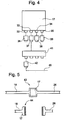
- FIG. 6 shows a schematic representation of a third modular embodiment of the device 17.
- a plug-in frame 45 acts as a cover.
- the processor CPU, central processing unit
- the various serial interfaces such as the Universal Serial Bus (USP), the RS232 connector, the modem, the Ethernet connection, the Line Manager Telephone (LU) and the LON are used as separate, independent modules 46 built and pushed into the plug-in frame 45.
- the communication between these separate modules 46 is provided by the back panel 47, which is also pushed into the plug-in frame 45 and has several plug pins to connect to the plugs of the modules 46.
- the back panel 47 achieves serial communication through a bus between the modules 46, which is characterized as being particularly flexible and free in terms of configuration.
- the power supply is integrated into the connector strip of the back panel by means of separate contacts.
- the modular structure of the device 17 in Figure 6 is also very convenient.
- the modules 46 can be inserted and pushed out as desired without the functionality of the device 17 being impaired and without operations for a new configuration of the device 17 having to be undertaken.
- the device 17 is in the Figure 6 placed in a thick, soft, removable rubber case that is easy to assemble and is drip-proof.
- the rubber housing provides protection against knocks and moisture and is aesthetically pleasing.
- the rubber housing can be implemented in various protective designs, depending on the operating and environmental requirements.
- a data acquisition of the device 17 is advantageously synchronized with the elevator travel.
- the acquisition of measurement data is controlled by the individual sequences of an elevator journey. This means that the recording of data can be made dependent on well-defined situations and circumstances. For example, vibration measurements can be carried out on the drive unit under very specific load conditions.
- Measurement data are recorded according to predefined criteria, compiled into data blocks and transmitted to a field office in accordance with specified rules. For example, door opening times can be monitored by regularly recording the associated measured values, compressing them when a certain amount of data is reached and sending the resulting data to a branch office for further processing.
- a special application can be represented by the vibroacoustic measurements .
- the drive unit is equipped with a sensor for detecting vibrations, for example an accelerometer, which enables the dynamic processes to be analyzed. This enables the drive unit to be diagnosed with regard to bearing damage, gear damage, imbalances and wear.
- the measuring unit can be attached to the drive unit for traction elevators and to the pump for hydraulic drives.
- the maintenance instructions can also be transmitted by the device 17.
- the instructions required for maintenance and / or repair are sent from an external location to the remote maintenance unit on the elevator installation.
- the technician arriving at the system can then view it with the help of a data display device and carry out the necessary work immediately.
- the execution of the instructions can be confirmed by the technician and then automatically communicated to the field office become.
- the delivery of maintenance instructions can also be generated as a direct result of a fault report.
- the routine transmission of measurement data to a branch office is advantageously carried out in a chronological order so that the connection costs minimally.
- the currently applicable tariffs are transmitted to the remote maintenance unit or retrieved from it, and the transmission is planned taking into account any priorities and delivery times to be observed for the messages. The transmission then takes place according to this planning.
- the device can, for example , initiate stress tests , ie the automatic loading of an elevator installation with travel orders to determine their robustness, availability and performance.
- stress tests ie the automatic loading of an elevator installation with travel orders to determine their robustness, availability and performance.
- driving requests are generated by a remote maintenance unit, transmitted to the system by floor and car calls and the processing of these calls is registered. The result of such a check can be communicated to a branch office for further processing.
- the device can also initiate automatic tests, for example.
- the acknowledgment of a fault message automatically triggers a corresponding test sequence to check that the fault has been rectified.
- the way in which the test is carried out can be made dependent, for example, on the content of the associated fault message.
- Test marks can be used in this context. When a malfunction is detected, a mark is generated and communicated to a branch office together with the associated malfunction report. With the help of this mark, certain test functions are subsequently accessible, which are no longer available after the malfunction has been rectified. This can relate to the remote initiation of a test drive using an analog telephone connection and DTMF-coded key information. The validity of a trademark can also expire if it is used.
- the device can carry out a control of the branch office.
- the availability of a branch office is checked by requesting an authentication feature and certain functions are modified according to the outcome of this check. For example, the range of functions can be restricted, settings re-parameterized or availability reduced.
- the elevator parameters can also be continuously adapted by the device. Data generated during operation are collected and transmitted to a control center for evaluation. This is done in such a way that a setting that is favorable to a certain extent is derived taking into account data from other systems. This setting is automatically transmitted to the corresponding system for further operation.
- information on the failure of a system can be used to achieve a test strategy that is optimal with regard to statistical variables. For this purpose, system-specific failures are recorded, parameters for describing the probability of failure of each system are determined in a central station and these are then transmitted to the system to adapt the test strategy.
Landscapes
- Indicating And Signalling Devices For Elevators (AREA)
- Maintenance And Inspection Apparatuses For Elevators (AREA)
- Elevator Control (AREA)
- Selective Calling Equipment (AREA)
Description
- Die Erfindung bezieht sich auf eine Vorrichtung und Verfahren zur fernwartung und Überwachung einer Aufzugsanlage gemäss der Definition der Patentansprüche.
- Zur Betriebssteuerung ist jeder Aufzugsanlage eine Aufzugssteuerung zugeordnet, an welche Sensoren und Aktoren, wie beispielsweise Bedien-, Betätigungs- und Stellelemente der Aufzugsanlage angeschlossen sind. Ein Mikroprozessor der lokalen Aufzugssteuerung liest die Eingangssignale und schaltet entsprechend dem vorgesehenen Steuer- bzw. Regelprogramm die Ausgangssignale. Die Verarbeitung der Signale und der in der Aufzugssteuerung gespeicherten, die Aufzugsanlage beschreibenden Angaben, wie z. B. Stockwerksanzahl, Antriebstyp etc. erfolgt in einem Mikroprozessor vor Ort bei der Aufzugsanlage.
- Aus den
Patentschriften EP 0 252 266 ,JP 04 235881 US 3 973 648 undUS 5 450 478 sind Aufzugsanlagen bekannt geworden, deren Aufzüge neben einer konventionellen Aufzugssteuerung zusätzlich mit einem Modem zur Fernwartung ausgestattet sind. Bei dieser Fernwartung von Aufzugsanlagen kommuniziert jeweils die Aufzugssteuerung jeder einzelnen Aufzugsanlage unter bestimmten Bedingungen mittels Modem über das öffentliche Telekommunikations-Netz mit einer zentralen Servicezentrale. Der dabei vorgesehene Datenaustausch betrifft in erster Linie vordefinierte diagnostische Daten im Hinblick auf Betriebszustand, Stör- und Alarmereignisse sämtlicher mit der zentralen Servicezentrale verbundenen Aufzugsanlagen. - In diesem Zusammenhang meint Fernwartungs-Funktion, dass diagnostische Daten, die einen bestimmten Teil oder eine Funktion eines Aufzuges betreffen, an eine bestimmte Servicezentrale übermittelt werden und in der Servicezentrale ausgewertet werden. Eine Fernwartungs-Funktion kann zum Beispiel die Beleuchtung in der Kabine oder die Schwingungen des Antriebs oder die Türöffnung überwachen. Wenn die Daten werden nur an die Servicezentrale übermittelt, ist die Fernwartungs-Funktion monodirektional. Wenn Daten werden auch nach der Auswertung in der Servicezentrale von der Servicezentrale zurück an die Aufzuganlage übermittelt, ist die Fernwartungs-Funktion bidirektional. Ein Fernwartungsmodul besteht aus mehreren Fernwartungs-Funktionen, die sich auf denselben Teil oder dieselbe Funktion eines Aufzuges beziehen, zum Beispiel Beleuchtung oder Türöffnung. Ein Fernwartungssystem besteht aus einer Aufzugsanlage, einer Servicezentrale für die Fernwartung des Aufzugs und aus deren Verbindung.
- Je nach Aufbau und Funktionsweise ist dem eigentlichen anlagenspezifischen Datenaustausch ein Datenaustauschprozedere vorgeschaltet, welches einerseits den Kommunikationsweg aufbaut anderseits den Zugriff bzw. die Zugriffsberechtigung auf Daten der Aufzugsteuerung regelt.
- Auf diese Weise mit einer aufzugsindividuellen Aufzugssteuerung samt Modemerweiterung und zentraler Servicezentrale ausgestattete Aufzugsanlagen haben sich bewährt, doch sind sie aufgrund ihrer insoweit erläuterten baulichen und funktionellen Eigenschaften vorrichtungsmässig aufwendig und nur eine beschränkte Auswahl vordefinierter Meldungen kann monodirektional in die Servicezentrale übertragen werden. Der Unterhalt der einzelnen im Gesamtsystem mit der Servicezentrale verbundenen, mitunter örtlich weit auseinanderliegenden Aufzugsanlagen gestaltet sich kostenintensiv, da bei Betriebsstörungen einer Aufzugsanlage oder eines Aufzugs lange Strecke für die Wartungsmonteure entstehen bis vor Ort die Ursache der Störung festgestellt und die Störung behoben wird. Bei Betriebsstörungen entstehen auch lange Wartezeiten.
- Diese herkömmlichen Fernwartungssysteme für Aufzugsanlage werden vor allem durch eine starre Konfiguration der Fernwartungsmodule gekennzeichnet, die umständlich und aufwendig eventuelle notwendige Anpassungen der Fernwartungs-Funktionen macht. Die Anzahl und die Art der Schnittstelle ist vordefiniert und limitiert die Flexibilität in dem Aufbau der Fernwartungs-Funktionen, welche durch die Kunden und den Markt verlangt werden.
- Eine hohe Flexibilität der Fernwartungsmodule wird vor allem verlangt, wenn eine bestehende Aufzugsanlage mit einem Fernwartungssystem modernisiert wird. Beispielweise besitzen die zu modernisierenden Aufzugsanlagen manchmal ein Fernalarmsystem, manchmal nicht. Bei der Modernisierung muss daher eine gegebenenfalls vorhandene Fernalarmierungsfunktion als Teil der Fernwartungsfunktionen berücksichtigt werden.
- Aufgabe der vorliegenden Erfindung ist es, eine Vorrichtung und Verfahren zur Fernwartung und Überwachung einer Aufzugsanlage der eingangs genannten Art anzugeben, die eine hohe Flexibilität in der Wahl und in der Konfiguration der Fernwartungs-Funktionen bereitstellen und die sich als kostengünstig erweisen.
- Diese Aufgabe wird durch die Erfindung gemäss der Definition der Patentansprüche gelöst.
- Die Vorrichtung weist mindestens einen Eingang auf, an den erste Signale von an der Aufzugsanlage angebrachten Sensoren und/oder von der Aufzugssteuerung übertragen werden, und weist mindestens einen Ausgang auf, über den an ein Telekommunikations-Netz angeschlossen wird. Alle zum Betrieb der Aufzugsanlage nötigen Sensoren und Aktoren können mit der Vorrichtung verbunden werden. Diese Informationen werden beispielsweise kabellos per Funk oder über kabelgebundenen Medien, wie Licht- oder Kupferleiter, etc... auf herkömmliche Weise übertragen. Beispielweise wird ein erstes Signal an einen Eingang übertragen, die Vorrichtung liest dieses erste Signal ein und/oder wertet es aus und/oder überarbeitet es. Die Vorrichtung leitet ein solches erstes Signal in der Form eines zweiten Signals über den Ausgang an das Telekommunikations-Netz weiter. Gegebenenfalls kann auch ein unbearbeitetes erstes Signal an ein Telekommunikations-Netz weitergeleitet werden. Die Vorrichtung ist gleichzeitig fähig, Signale vom Telekommunikations-Netz aufzunehmen und diese an die Aufzugssteuerung als Befehle bzw. Informationen zu übertragen und/oder umzuwandeln.
- Erfindungsgemäss ist ein Set von Fernwartungsfunktionen gespeichert und aktivierbar. Vorzugsweise wird das Set von Fernwartungsfunktionen in einen Datenspeicher der Vorrichtung geladen.
- Gegebenenfalls wird die Vorrichtung zwecks Aktivierung einer Fernwartungsfunktion konfiguriert, d.h. Hardware und Software Anpassungen werden auf der Vorrichtung vorgenommen, damit die Vorrichtung erkennt, dass ein an einen bestimmten Eingang eingehendes erstes Signal beispielweise die Beleuchtung der Aufzugskabine darstellt und/oder das ein zweites Signal über einen bestimmten Ausgang an das Telekommunikations-Netz übermittelt wird. Vorzugsweise wird die Konfigurierung der Fernwartungs-Funktionen durch Hardware und Software Anpassungen der Vorrichtung durchgeführt. Die Universalität und die Normierung der eingesetzten elektronischen Bauelemente ermöglicht, eine hohe Flexibilität der Fernwartungs-Funktionen zu erzielen. Der Aufbau der Fernwartungs-Funktionen ist modular. Die Fernwartungs-Funktionen sind leicht erweitbar und nachrüstbar. Vorteilhafterweise werfolgt diese Anpassung der Vorrichtung über eine I/O-Box zwischen Aufzugsanlage und Vorrichtung. Diese einfache Anpassung der Vorrichtung über eine Schnittstelle an alle Arten von Aufzugsanlagen erlaubt die Vereinheitlichung heterogener Anlagen-Portfolios aus sicht der Servicezentrale. Das heisst, dass verschiedene proprietäre Aufzugsanlagen über die Schnittstelle mit standardisierten Fernwartungs-Funktionen betrieben werden können.
- Als Aktivierung einer Fernwartungs-Funktion wird das Laden einer FernwartungsFunktion vom Speicher in den Prozessor definiert, so dass die Vorrichtung vollständig bereit ist, die von einer Fernwartungs-Funktion vorgesehenen Operationen durchzuführen.
- Da die Vorrichtung hardwaremässig beliebig konfigurierbar nach der Zahl und Art der ankommenden Signale sind, werden Fernwartungs-Funktionen in einem entsprechenden Datenspeicher als Set beziehungsweise Software Programme gespeichert, entfernt, ausgewählt, aktiviert und deaktiviert.
- Durch Laden eines Software Programms in einen Datenspeicher der Vorrichtung wird eine oder mehrere Fernwartungs-Funktionen als Set im allgemeinen hinzugefügt und/oder entfernt. In diesem Fall genügt die Aktivierung einer Fernwartungs-Funktion, zum Beispiel durch die Wahl dieser Funktion in einem Menu des Software Programms und das Laden der entsprechenden Software in den Prozessor, um das Software Programm für die neue Fernwartungs-Funktion bereitzustellen.
- Vorteilhafterweise werden die Wartungsfunktionen und die Programme über das Telekommunikationsnetz übertragen, so dass die Übertragung so schnell wie möglich erfolgen kann.
- Neue Fernwartungs-Funktionen können auch ohne Betriebsunterbrechung der Aufzugsanlage aktiviert oder hinzugefügt werden, da die Vorrichtung nicht unbedingt notwendig für den Normalbetrieb des Aufzugs ist und separat zum Normalbetrieb erfolgen kann. Vorteilhafterweise hat die Aktivierung einer Fernwartungs-Funktion keine Betriebsunterbrechung anderer Fernwartungsfunktionen, welche von der aktivierten Funktion nicht betroffen werden, zur Folge.
- Hieraus resultierende Vorteile bestehen darin, dass die Vorrichtung leicht montierbar und demontierbar ist, so dass die Aufzugsanlage mit oder ohne Fernwartungs-Funktionen zu betreiben ist. Die Zahl und die Art der Schnittstellen zwischen Vorrichtung und Aufzugsanlage sind variabel und frei konfigurierbar, so dass die Fernwartungs-Funktionen ausgewählt oder entfernt werden.
- Bei Übertragung sämtlicher Aufzugsanlagendaten und Aufzugsanlagenparameter zur Servicezentrale des Gesamtsystems ist eine zentrale Fernwartung über diese Technik möglich. Zeit- und lohnintensive Einstellungen und Anpassungen vor Ort an dem Aufzug entfallen oder werden explizit planbar. Durch Modifikation der Software der Servicezentrale und/oder der Vorrichtung lassen sich Aufzugsfunktionen sowohl für einzelne als auch mehrere Aufzüge beeinflussen. Weiter ist es möglich, einen vollständigen Istzustand der Aufzugsanlage in der Servicezentrale abzubilden und Daten, die Benutzungsrechte, Fahrtziele usw. betreffen an zentraler Stelle zu korrigieren.
- Darüber hinaus sind mit der erfindungsgemässen Vorrichtung völlig neue Formen der Aufzugsanlagenüberwachung, vorbeugenden Fernwartung und Instandhaltung möglich. Neben den Steueralgorithmen erfolgt eine separate Auswertung der Gebersignale für eine Verschleiss- und Ausfallanalyse. Jede Baugruppe wird vorbeugend analysiert und statistisch ausgewertet. Dem Kunden werden Informationen über die Anlage in beliebiger Form zur Verfügung gestellt (z.B. Internetseiten statt Lobby-PC).
- Vorteilhafterweise wird die Vorrichtung versteckt, dissimuliert und für den Monteur/Benutzer nicht sichtbar gemacht, damit unautorisierte und fremde Personen die Aufzugsanlage nicht sabotieren, manipulieren oder fernsteuern können.
- Im folgenden wird die Erfindung anhand von beispielhaften Ausführungsformen gemäss der
Figuren 1-5 im Detail erläutert. Hierbei zeigt: -
Fig. 1 eine schematische Darstellung einer durch die Vorrichtung ferngesteuerten Aufzugsanlage, -
Fig. 2 eine schematische Darstellung einer Ausführungsform der Vorrichtung, -
Fig. 3 eine schematische Darstellung von verschiedenen Sensoren in der Aufzugsanlage, -
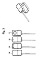
Fig. 4 ein Blockdiagramm einer möglichen Konfiguration von USB Steckern und Adaptern, die an einer erfindungsgemässen Vorrichtung angeschlossen werden, -
Fig. 5 eine mögliche ästhetische Gestaltung einer erfindungsgemässen Vorrichtung, die in Form eines intelligenten Kabels oder eines intelligenten Steckers erscheint, -
Fig. 6 eine schematische Darstellung einer dritten modularen Ausführungsform der Vorrichtung. -
Fig. 1 zeigt eine schematische Prinzipdarstellung.
In derFigur 1 ist mit 1 eine Aufzugsanlage bezeichnet, die eine im Schacht 2 verfahrbare Aufzugskabine 3 aufweist. Aufzugsanlage 1 kann wie in diesem Ausführungsbeispiel ein einzelner Aufzug sein oder aber auch eine Anlage mit mehreren, zu einer Gruppe steuerungstechnisch verknüpften Aufzügen in einem Gebäude. Die Aufzugskabine 3 ist an Seilen 4 aufgehängt, die über eine Treibscheibe 5 geführt sind. Die Treibscheibe 5 wird mittels der Antriebsmaschine 6 in Bewegung gesetzt, die über eine Aufzugssteuerung 7 mit elektrischer Energie versorgt wird. Zur Überwachung der Bewegung der Treibscheibe 5 und somit der Position der Aufzugskabine 3 im Schacht 2 ist beispielweise ein Positionssensor 8 vorgesehen. Im Maschinenraum 9 befindet sich z.B. am Antriebsmotor auch ein Temperatursensor 10. Ein anderer Stromsensor 11 misst beispielweise einen Strom in der Aufzugssteuerung 7. In der Aufzugskabine 3 gemässFigur 1 ist ein Kabinentableau 12 angeordnet, über das die Fahrziele eingegeben werden. Im Kabinentableau werden ein Alarmknopf 13 und ein Mikrophon 14 und/oder ein Lautsprecher angeordnet, die durch eine Leitung zu einem Telekommunikations-Netz 16 verbunden werden. Die Signalleitungen sind mit unterbrochenen Linien dargestellt. - Als wesentliches Merkmal der Erfindung wird eine Vorrichtung 17 in der Form eines schematisierten Kastens nach
Figur 1 durch einen Ausgang 15 an dem Telekommunikations-Netz 16 angeschlossen, welche die von den Sensoren 8, 10 und 11 generierten und durch den Eingang 18 übertragenen Signale sammelt und verarbeitet. Die Vorrichtung 17 nimmt auch direkt durch die serielle Verbindung mit der Aufzugssteuerung 19 serielle Signale der Aufzugssteuerung auf. Bei der beschriebenen Ausführung sind die Aufzugsanlagen 1 und die Servicezentrale 20 über das Telekommunikations-Netz 16 miteinander verbunden, das das öffentliche Telefonnetz darstellt. Bei Kenntnis der vorliegenden Erfindung kann der Fachmann natürlich auch andere Arten der Verbindung zwischen Vorrichtung und Aufzugssteuerung wie beispielsweise eine parallele Verbindung realisieren. - In einer bevorzugten Ausführung wird eine nicht in
Figur 1 gezeigte I/O Box als Schnittstelle zwischen der Vorrichtung 17 und der Aufzugsanlage eingeführt, welche die aus der Aufzugssteuerung, der Aufzugskabine, dem Aufzugsschacht und dem Maschinenraum ankommenden parallen Signale in serielle Signale umwandelt, so dass sie dann seriell durch einen Bus an die Vorrichtung 17 übermittelt werden können. Die I/O Box weist mehrere Eingänge für parallele Signale auf. Jeder Eingang entspricht einem bestimmten Signal und wird mit dem entsprechenden von der Aufzugsanlage geführten Kabel verbunden. Der Ausgang der I/O Box ist typischerweise ein UBS Stecker, an dem ein Bus angeschlossen wird, der die Daten an die Vorrichtung 17 übermittelt. - Eine grosse Zahl von Kabeln der Aufzugsanlage müssen ordentlich und sicher an die entsprechenden Ein- und Ausgänge der I/O Box verbunden werden, was die Anwendung von Markierungssystemen dieser Ein- und Ausgänge verlangt. Charakteristisch ist der zentrale Kabelkanal für die Kabelzuführung. Diese zugeführten Kabel werden, über die Markierungs- und Führungslogik in der I/O-Box, in Eingangs- und Ausgangskanäle sowie einen logische, physischen Bereich für den Sicherheitskreis aufgeteilt. Die Kabelführung in der I/O Box sieht auch Zugentspannungsgeometrien zur Zugentlastung und Stützflächen vor, wo die Kabel aufliegen, um Bruche zu vermeiden.
- Für jeden Eingang der I/O Box kann ein LED vorgesehen werden, dessen Blinken bestätigt, ob der Eingang richtig funktioniert oder nicht und eine rasche optische Kontrolle der Funktionalität der I/O Box bzw. des aktuellen Zustandes des gesamten Aufzugssystems ermöglicht. Ein Temperatursensor wird vorzugsweise in der I/O Box vorgesehen, um Hitzschaden zu vermeiden.
- Vorzugsweise wird die Vorrichtung 17 während der Inbetriebnahme sich automatisch konfigurieren und von selbst lernen, welcher Eingang der I/O Box welchem Signal entspricht. Eine Lernfahrt der Aufzugskabine von unten nach oben wird beispielweise bewirkt. Während der Fahrt misst die Vorrichtung 17 die von den Eingängen der I/O Box ankommenden Signale und kann dadurch zu jedem Eingang das entsprechende physikalische Signal der Aufzugsanlage zuteilen. Die Vorrichtung 17 führt auch einen Plausibilitätstest der Zuteilung der Signale an die Eingänge der I/O Box aus. Damit werden Logik-Fehler in der Verkabelung der I/O Box automatisch erkannt, kenntlich gemacht und lassen sich so einfach und rasch korrigieren. Während der Lernfahrt erkennt die Vorrichtung 17 automatisch die Zahl der Stockwerke im Gebäude, den Typ der Aufzugstüre und des Aufzugsantriebes sowie noch andere wichtige Eigenschaften der Aufzugsanlage.
- Die Vorrichtung 17 muss nicht unbedingt an eine I/O Box oder an eine Aufzugsanlage direkt angeschlossen werden, sondern kann auch sich an eine weitere Vorrichtung 17 durch einen Bus angeschlossen werden, wodurch eine Hub-Funktion realisiert wird. Dieses modulare Konzept erlaubt dem Fachmann bei Kenntnis der vorliegenden Erfindung grosse Erweiterungsmöglichkeiten der Vorrichtung.
- Die Vorrichtung 17 kann auch die Form eines intelligenten Kabels oder eines intelligenten Steckers annehmen. Sie ist möglichst kostengünstig, klein, einfach nachrüstbar, montierbar und demontierbar. Dazu steht die Servicezentrale 20 über eine Datenübertragungseinrichtung mit sämtlichen Aufzügen eines Anlagensystems in Verbindung. Aufzugsdaten und Parameter werden zwischen jeder Aufzugsanlage und der Servicezentrale kommuniziert. Die Eingänge der Vorrichtung 17 werden zum Beispiel durch USB Stecker (Universal Serial Bus) und Feldbus an den Kabeln verbunden, die die von der Aufzugsanlage generierten Signale übertragen.
-
Figur 1 zeigt eine Servicezentrale 20, welche den Betrieb der Aufzugsanlagen 1 regelt und den Wartungsstand der Aufzugsanlagen 1 überwacht und aufzeichnet. Die Servicezentrale 20 setzt sich zusammen aus einem Rechnersystem 21 und aus einer Datenbank 22 in der Wartungs- und betriebszustandsrelevante Daten abgelegt werden. Das Rechnersystem 21 und die Datenbank 22 sind über einen Datenbus 23 verbunden. Über den Datenbus 23 können mit Hilfe zusätzlicher Datenverarbeitungseinrichtungen entweder die in der Datenbank 22 abgelegten Daten und/oder aktuelle Betriebsdaten der Aufzugsanlagen 1 abgerufen und zur zusätzlichen Auswertung weiterverarbeitet werden. - Die übertragenen Informationen werden in der Servicezentrale 20 im Rechnersystem 21 verarbeitet. Das Rechnersystem 21 leitet aus den empfangenen Informationen auch die Stellbefehle zum Betrieb der Anlagen 1 ab. Diese Stellbefehle werden dann von der Servicezentrale 20 mit Hilfe der Vorrichtung 17 an die Aufzugsanlagen 1 übertragen. An jeder Aufzugsanlage 1 leitet die Vorrichtung 17 die Stellbefehle weiter. Die Vorrichtung 17 steuert die Stellglieder bzw. Aktoren, wie z. B. die Antriebsmaschine 6 oder die Anzeigeeinrichtungen.
- Ungewöhnliche durch die Vorrichtung 17 detektierte Zustände der Aufzugsanlage können unmittelbar zur Servicezentrale 20 gemeldet werden. Die Servicezentrale 20 ist so organisiert, dass sie sofort nach einer Störungsmeldung einen Auftrag einem einem Netzwerk gehörenden Wartungstechniker gemäss Fähigkeit und/oder Verfügbarkeit verteilt, damit der Aufzugsanlage so bald wie möglich repariert wird. Somit ist ein Diagnose-System integriert, welches als Expertensystem eine effektive und effiziente Problembehebung sowie Wartung der Aufzugsanlage ermöglicht.
- Bei der beschriebenen Ausführung können die Aufzugsanlagen 1 und die Servicezentrale 20 auch über das öffentliche mobile Telekommunikations-Netz 24 miteinander verbunden werden. In diesem Fall werden ein GSM Modem und eine GSM SIM-Karte in der Vorrichtung 17 vorgesehen, die für die mobile Telekommunikation sorgen. Vorzugsweise wird die Software der GSM Karte mit Kodierungssystemen ausgerüstet, um vom Missbrauch geschützt zu werden. Die durch die Vorrichtung 17 bewerkstelligte mobile Telekommunikation ermöglicht zum Beispiel, dass ein Techniker vor der persönlichen Präsenz im Gebäude der Aufzugsanlage per Handy, GSM oder Laptop eine Kontrolle und Diagnose der Funktionalität der Aufzugsanlage ausführen kann.
- Durch die telephonische Linie 16 oder 24 kann die Vorrichtung 17 an Ethernet oder Firewire angeschlossen und somit fernüberwacht und -programmiert werden.
-
Figur 2 zeigt eine schematische Darstellung einer möglichen Ausführungsform der Vorrichtung 17. Ein Kasten 25 dient als Gehäuse und wirkt als Hülle und beinhaltet einen Prozessor (CPU, central processing unit) und einen Datenspeicher, die in der Figur nicht aufgezeichnet sind. Der Eingang 18 des Kastens besteht aus einem Sensorbus, zum Beispiel USB (Universal serial bus), der die von den Sensoren (8, 10, 11) generierten Signale überträgt. Der Ausgang 15 des Kastens besteht aus einem Telecombus 26, zum Beispiel RJ45, der Signale an einem Telekommunikations-Netz übermittelt. Die notwendige elektrische Energie wird beispielweise durch den Steckernetzteil 27 versorgt. Ein weiterer nicht gezeigter Ausgang ermöglicht einen direkten Zugriff an der CPU und an dem Datenspeicher des Kastens 25 durch einen PC. Ein weiterer nicht gezeigter Eingang übermittelt serielle Signale der Aufzugssteuerung 7 direkt an den Kasten 25. Wie inFigur 2 zu entnehmen ist, wird der Kasten 25 vorteilhaftweise in eine Halterung hineingesteckt, damit er einfach und schnell montiert und demontiert werden kann. -
Figur 3 zeigt eine schematische Darstellung von verschiedenen Sensoren, deren Signale am Eingang 18 des Kastens 25 übermittelt werden können. 28 ist eine Ausführung eines Temperatursensors, der im Maschinenraum 9 bzw. an der Antriebsmaschine 6 bzw. im Schachttürbereich angebracht werden kann. 29 ist eine Ausführung eines Stromsensors, der in der Aufzugssteuerung 7 angebracht werden kann. 30 ist eine Ausführung eines Mikrophons und 31 ist eine Kamera, die am Wand der Aufzugskabine 3 montiert werden. Noch viele andere Typen von Sensoren sind vorstellbar, deren Signale am Eingang 18 des Kastens 25 übermittelt werden können, zum Beispiel Sensoren, die eine Distanz, die Dehnung, die Nivellierung der Aufzugskabine, die Geschwindigkeit, die Erschütterung (Beschleunigung), die Vibrationen, den Ruck, das Moment, den Druck, die Kraft, die Lichtmenge, die Helligkeit, den Füllstand, die Dichte, das Magnetfeld, die Feuchte, den Rauch, die Abgase, den Geschmack, den Geruch, und/oder eine Leitfähigkeit messen. Wie inFigur 3 zu entnehmen ist, werden die Sensoren vorteilhaftweise in eine Halterung hineingesteckt, damit sie einfach und schnell montiert und demontiert werden können. - Noch andere Detektoren für Sprengstoffe, Vandalismus und Seilüberwachung können an die Vorrichtung 17 angeschlossen werden, die somit auch die Funktion einer Sicherheitseinrichtung ausüben kann. Die Übermittlung einer Kombination von Messwerten an die Vorrichtung 17 ist auch möglich.
- Vielfältige externe Geräte können an die Vorrichtung 17 angeschlossen werden, wie Kameras, Mikrophone, automatische Systeme für die Zutrittskontrolle, die Identifikation und die Zuteilung von Aufzügen (z.B. Schindler ID), oder automatische Systeme für die Sicherheitsüberwachung einer Aufzugsanlage (z.B. Qualison).
Beispiele von Fernwartungs-Funktionen, die durch die Vorrichtung 17 übernommen werden können, sind: Auslösen von Testfahrten und Lernfahrten, Fahrtzählen, Zählen der Türöffnungen, Meldung einer offenen Tür, Fernalarmierung, Störungsmeldungen, Fernsteuerung von bestimmten Aufzugsfunktionen, Angaben über den Zustand des Aufzugs, den Zustand der Türe, den Zustand von bestimmten Relais, die Aufzugsposition, die Fahrtrichtung, Fernzugriff auf den Aufzugszustand und -Daten, Kontrolle der Zutrittsrechte, statistische Analyse des Verkehrs, Kontrolle des Zustandes der tragenden Seile, der Anhaltegenauigkeit, Kontrolle der Aufzugskabine durch eine Kamera, Temperatursensoren z.B. für den Antriebsmotor, die Kabine oder den Aufzugsschacht, Rauchdetektoren, Ferndiagnose und -Reparatur, durch Reset der Aufzugssteuerung zum Beispiel, Messung und Auswertung von Vibrationen, Messungen von Spannung, Strom, Helligkeit, Beleuchtung, Temperatur, Position der Kabine, direkte Einwirkung auf bestimmte Relais-Ausgänge, z.B. Zuschalten eines Ventilators. - Die Vorrichtung 17 kann auch automatisch Blinklichte in der Aufzugsanlage betätigen, Anzeige und Texte zusammenstellen und zeigen und Signalisierungselemente aktivieren.
- Diese Liste ist nicht erschöpfend. Bei Kenntnis der vorliegenden Erfindung kann der Fachmann noch weitere Fernwartungs-Funktionen sich vorstellen und einführen. Weitere Anwendungen der Vorrichtung 17 werden am Ende dieser Schrift beschrieben.
-
Figur 4 zeigt ein Blockdiagramm einer möglichen Konfiguration von USB Steckern, die an einer erfindungsgemässen Vorrichtung angeschlossen werden können. Es wird auch erläutert, wie eine Fernwartungs-Funktion aktiviert wird.
Zu Beginn besitzt die Vorrichtung 17 vier Stecker USB (Universal serial bus) 32-35. Der USB Stecker 32 steht in Verbindung mit einem seriellen Adapter 36, die die Signale der Aufzugssteuerung aufnimmt. Das Kommunikationsprotokoll ist beispielsweise RS232 (recommended standard 232). Der USB Stecker 33 steht in Verbindung mit einem Hub Adapter 37 (Verkehrsknotenpunkt). Der USB Stecker 34 steht in Verbindung mit einem Netzwerk Adapter 38, die für das Kommunikationsprotokoll Ethernet vorgesehen ist. Der USB Stecker 35 steht in Verbindung mit einem Modem Adapter 39, die für die Verbindung mit dem Telekommunikations-Netz sorgt. Mögliche Kommunikationsnetzwerke sind: PSTN (public switched telephone network), ISDN (integrated service digital network), GSM (global system mobile communication), DSL (digital subscriber line).
Nehmen wir jetzt an, dass die Aufzugsanlage beispielweise eine Fernwartungs-Funktion "Messung der Helligkeit der Kabine" benötigt. Die Aktivierung dieser neuen Funktion erfolgt durch den Einsatz von Hardware und/oder Software Mitteln. Ein Helligkeitssensor muss natürlich in der Aufzugskabine installiert sein und durch ein Helligkeitssensorskabel 40 an der Vorrichtung 17 angeschlossen werden. Die Schnittstelle mit der Vorrichtung 17 wird wie Folgendes ausgeführt: - Ein zusätzlicher USB Stecker 41 mit zum Beispiel 4 USB Ausgängen wird an dem Hub Adapter 37 (Verkehrsknotenpunkt) angeschlossen.
- Ein Feldbus Adapter 42 wird mit einem der USB Ausgänge des zusätzlichen USB Steckers verbunden, um durch ein Protokoll das Signal des Helligkeitssensorskabels 40 zur Vorrichtung 17 kommunizieren zu können.
- Die drei anderen USB Ausgänge des zusätzlichen USB Steckers 41 bleiben verfügbar für die Signale von noch anderen Sensoren, die eventuell eingeführt werden müssen.
- Durch den Einsatz des zusätzlichen USB Steckers 41 in der Vorrichtung 17 und die Aktivierung der entsprechenden Fernwartungs-Funktion" Messung der Helligkeit der Aufzugskabine " im Software Programm wird das Fernwartungssystem auf eine rasche, billige und einfache Weise fähig gemacht, auch die Helligkeit der Aufzugskabine fern zu überwachen. Diese Flexibilität und Schnelligkeit in der Konfiguration der durch die Vorrichtung 17 angebotenen Fernwartungs-Funktionen haben keinen Präzedenzfall im Stand der Technik.
- Die Vorrichtung 17 kann beispielweise das Aussehen eines Kastens bzw. einer Box haben, wie in
Figur 3 gezeigt; sie kann beliebig, beispielsweise im Maschinenraum im Schaltschrank, am Schaltschrank, am Boden, am Wand oder in der Aufzugssteuerung positioniert werden. Die Vorrichtung 17 kann aber auch die Form eines intelligenten Steckers oder intelligenten Kabels haben, die ihre Fernwartungs-Funktionen und ihre Schaltungen komplett oder teilweise dissimulieren und verstecken können. Ein intelligentes Kabel oder intelligenter Stecker können somit erzielt werden, die eine fälschungssichere Fernwartung der Aufzugsanlage ermöglichen: nur autorisierte und kompetente Monteure erkennen die Anwesenheit der Vorrichtung 17 und können die Fernwartungs-Funktionen einschalten oder ausschalten.Fig. 5 zeigt eine mögliche ästhetische Gestaltung einer erfindungsgemässen Vorrichtung, die in Form eines intelligenten Kabels 43 oder intelligenten Steckers 44 erscheint. In diesem Fall liegt die Vorrichtung 17 zusammen mit dem System von Kabeln, mit denen sie in Verbindung steht und die sich auch ausserhalb der Aufzugsanlage befinden können. Die Box und/oder das Kabel und/oder der Stecker sind vorteilhafterweise austauschbar mit der Aufzugsanlage verbunden und können einfach und schnell auf eine praktische Weise ausgetauscht werden. -
Figur 6 zeigt eine schematische Darstellung einer dritten modularen Ausführungsform der Vorrichtung 17. Ein Steckrahmen 45 wirkt als Hülle. Der Prozessor (CPU, central processing unit) und die verschiedenen seriellen Schnittstellen, wie der Universal Serial Bus (USP), der Stecker RS232, das Modem, der Ethernet Anschluss, der Line Manager Telephone (LU) und der LON werden als separate unabhängige Module 46 gebaut und in den Steckrahmen 45 eingeschoben. Für die Kommunikation zwischen diesen separaten Modulen 46 sorgt der Back Panel 47, der auch in den Steckrahmen 45 eingeschoben wird und mehrere Steckerstifte aufweist, um sich mit den Steckern der Module 46 zu verbinden. Durch den Back Panel 47 wird eine serielle Kommunikation durch einen Bus zwischen den Modulen 46 erzielt, die sich als besonders flexibel und frei in der Konfiguration auszeichnet. Gleichzeitig ist in der Steckerleiste des Backpanels die Stromversorgung mittels separaten Kontakten integriert. - Der modulare Aufbau der Vorrichtung 17 in
Figur 6 ist auch sehr praktisch. Die Module 46 können beliebig eingeschoben und herausgeschoben werden, ohne dass die Funktionalität der Vorrichtung 17 beeinträchtigt wird und ohne dass Operationen für eine neue Konfigurierung der Vorrichtung 17 unternommen werden müssen. - Vorzugsweise wird die Vorrichtung 17 in der
Figur 6 in ein dickes weiches entfernbares Gummigehäuse eingelegt, das leicht montierbar und tropfwasserdicht ist. Das Gummigehäuse verschafft einen Schutz gegen Schläge, Feuchtigkeit und ist ästhetisch angenehm. Das Gummigehäuse lässt sich, je nach Betriebs- und Umgebungs-Anforderungen, in verschiedenen Schutzausführungen realisieren. - Vorteilhafterweise wird eine Datenerfassung der Vorrichtung 17 mit der Aufzugsfahrt synchronisiert. Die Erfassung von Messdaten wird dabei durch die einzelnen Sequenzen einer Aufzugsfahrt gesteuert. Dies bedeutet, dass die Aufnahme von Daten von wohlbestimmten Situationen und Gegebenheiten abhängig gemacht werden kann. So lassen sich beispielsweise Vibrationsmessungen an der Antriebseinheit bei ganz bestimmten Lastverhältnissen vornehmen.
- Vorteilhafterweise wird auch eine Automatische Erfassung von Messdaten vorgesehen. Messdaten werden gemäss vordefinierten Kriterien aufgenommen, zu Datenblöcken zusammengestellt und gemäss vorgegebenen Regeln einer Aussenstelle übermittelt. So lassen sich beispielsweise Türöffnungszeiten überwachen, indem die zugehörigen Messwerte regelmässig erfasst, bei Erreichen einer bestimmten Datenmenge eine Komprimierung derselben vorgenommen wird und die resultierenden Daten einer Aussenstelle zur Weiterverarbeitung zugestellt werden.
- Eine spezielle Anwendung kann durch die vibroakustischen Messungen dargestellt werden. Die Antriebseinheit wird mit einem Sensor zur Erfassung von Schwingungen, zum Beispiel einem Beschleunigungsaufnehmer, ausgestattet, wodurch eine Analyse der dynamischen Abläufe erfolgen kann. Dies ermöglicht eine Diagnose der Antriebseinheit betreffend Lagerschäden, Getriebeschäden, Unwuchten und Abnutzung. Die Messeinheit kann bei Traktionsaufzügen an der Antriebseinheit, bei hydraulischem Antrieb an der Pumpe, angebracht werden.
- Die Wartungsanleitungen können auch durch die Vorrichtung 17 übermittelt werden. Abhängig vom aktuellen Zustand und Betriebsbereitschaft eines Aufzuges werden die zur Wartung und/oder Reparatur notwendigen Anleitungen von einer Aussenstelle an die Femwartungseinheit an der Aufzugsanlage zugestellt. Der an der Anlage eintreffende Techniker kann diese dann mit Hilfe eines Datensichtgeräts einsehen und die notwendigen arbeiten unverzüglich ausführen. Die Ausführung der Anweisungen kann durch den Techniker bestätigt werden und anschliessend automatisch der Aussenstelle mitgeteilt werden. Die Zustellung von Wartungsanleitungen kann auch als direkte Folge einer Störungsmeldung erzeugt werden.
- Vorteilhafterweise erfolgt die routinemässige Übermittlung von Messdaten an eine Aussenstelle zeitlich so geordnet, dass minimale kosten für die Verbindung entstehen. Dazu werden die jeweils aktuell geltenden Tarife an die Femwartungseinheit übermittelt, oder von dieser abgerufen, und eine Planung der Übertragung unter Berücksichtigung allfälliger Prioritäten und einzuhaltender Lieferzeiten der Nachrichten durchgeführt. Die Übermittlung erfolgt dann entsprechend dieser Planung.
- Die Vorrichtung kann zum Beispiel Stress-Tests initiieren, d.h. die automatische Beaufschlagung einer Aufzugsanlage mit Fahraufträgen zur Ermittlung deren Robustheit, Verfügbarkeit und Leistungsfähigkeit. Dazu werden von einer Fernwartungseinheit Fahranforderung generiert, durch Stockwerks- und Kabinenrufe an die Anlage übermittelt und die Abarbeitung dieser Rufe registriert. Das Ergebnis einer solchen Prüfung kann einer Aussenstelle zur Weiterverarbeitung mitgeteilt werden.
- Die Vorrichtung kann zum Beispiel auch automatische Tests initiieren. Die Quittierung von Störungsmeldung hat automatisch die Auslösung einer entsprechenden Testsequenz zur Prüfung der Störungsbehebung zur Folge. Die Art und Weise des ausgeführten Tests kann etwa vom Inhalt der zugehörigen Störungsmeldung abhängig gemacht werden.
- Testmarken können in diesem Zusammenhang verwendet werden. Bei Detektion einer Störung wird eine Marke generiert und zusammen mit der zugehörigen Störungsmeldung einer Aussenstelle mitgeteilt. Mit Hilfe dieser Marke sind in der Folge bestimmte Testfunktionen zugänglich, welche nach Behebung der Störung nicht mehr zur Verfügung stehen. Dies kann etwa die Fernauslösung einer Testfahrt mittels einer analogen Telefonverbindung und DTMF-kodierter Tasteninformationen betreffen. Die Gültigkeit einer Marke kann auch bei deren Anwendung verfallen.
- Die Vorrichtung kann unter Umständen eine Kontrolle der Aussenstelle durchführen. Die Verfügbarkeit einer Aussenstelle wird durch die Anforderung eines Authentifizierungsmerkmals überprüft und bestimmte Funktionen entsprechend dem Ausgang dieser Prüfung modifiziert. So kann etwa der Funktionsumfang eingeschränkt, Einstellungen umparametriert oder die Verfügbarkeit reduziert werden.
- Die Aufzugsparameter können auch ständig durch die Vorrichtung angepasst werden. Während des Betriebs anfallende Daten werden gesammelt und einer Zentrale zur Auswertung übermittelt. Diese erfolgt derart, dass unter Beachtung von Daten anderer Anlagen eine in einem bestimmten Masse günstige Einstellung abgeleitet wird. Diese Einstellung wird der entsprechenden Anlage zum weiteren Betrieb automatisch übermittelt. In konkreter Ausführung können etwa Angaben zum Ausfall einer Anlage dazu verwendet werden, eine in bezug auf statistische Grössen optimale Teststrategie zu erzielen. Dazu werden Ausfälle anlagenspezifisch erfasst, in einer Zentrale Parameter zur Beschreibung der Ausfallwahrscheinlichkeit jeder Anlage ermittelt und diese dann der Anlage zur Anpassung der Teststrategie übermittelt.
Claims (20)
- Vorrichtung (17) zur Fernwartung und Überwachung einer Aufzugsanlage (1), mit mindestens einem Eingang (18) zum Erfassen von ersten Signalen von der Aufzugssteuerung (7) und/oder von einem Sensor (8, 10, 11, 28, 29, 30, 31),
mit mindestens einem Ausgang (15) von zweiten Signalen zu einem Telekommunikations-Netz (16, 24),
mit mindestens einem Prozessor und einem Datenspeicher,
dadurch gekennzeichnet, dass im Datenspeicher ein Set von Fernwartungsfunktionen gespeichert ist, wobei das Set von Fernwartungsfunktionen zumindest ein Element aufweist aus der Gruppe bestehend aus Überwachung der Spannungsmessungen in der Kabine, Temperaturüberwachung und Aktivierung einer Kamera,
und dass mindestens eine dieser Fernwartungs-Funktionen beliebig aktivierbar ist. - Vorrichtung gemäß Patentanspruch 1, dadurch gekennzeichnet, dass die Fernwartungs-Funktion Hardware und Software der Vorrichtung konfiguriert und dass eine Fernwartungs-Funktion durch Laden aus dem Datenspeicher in den Prozessor aktivierbar ist.
- Vorrichtung gemäß Patentanspruch 1 oder 2, dadurch gekennzeichnet, dass eine aktivierte Fernwartungs-Funktion erste Signale auswertet und ein dem Ergebnis der Auswertung entsprechendes zweites Signal ausgibt.
- Vorrichtung gemäß einem der vorhergehenden Patentansprüche ,
dadurch gekennzeichnet, dass der Sensor ein Sensor für Temperatur (10, 28) und/oder Strom (11, 29)/Spannung und/oder Audio (14, 30)/Video (31) aus der Aufzugskabine (3)/Schacht (2) und/oder Distanz und/oder Dehnung und/oder Nivellierung der Aufzugskabine und/oder Geschwindigkeit und/oder Erschütterung (Beschleunigung) und/oder Vibrationen und/oder Ruck und/oder Moment und/oder Druck und/oder Kraft und/oder Lichtmenge und/oder Helligkeit und/oder Füllstand und/oder Dichte und/oder Magnetfeld und/oder Feuchte und/oder Rauch und/oder Abgase und/oder Geschmack und/oder Geruch und/oder Leitfähigkeit ist. - Vorrichtung gemäß einem der vorhergehenden Patentansprüche,
dadurch gekennzeichnet, dass eine I/O Box als Schnittstelle zwischen der Vorrichtung und der Aufzugsanlage eingeführt ist, welche die aus der Aufzugssteuerung, der Aufzugskabine, dem Aufzugsschacht und dem Maschinenraum ankommenden parallelen Signale in vorzugsweise serielle Signale umwandelt und an die Vorrichtung übermittelt. - Vorrichtung gemäß Patentanspruch 5,
dadurch gekennzeichnet, dass an verschiedene proprietäre Aufzugsanlagen angepasste Schnittstelle vorgesehen sind und dass diese Schnittstellen standardisierte Signale an die Vorrichtung übermitteln, so dass diese Aufzugsanlagen mit standardisierten Fernwartungs-Funktionen betreibbar sind. - Vorrichtung gemäß einem der vorhergehenden Patentansprüche,
dadurch gekennzeichnet, dass die Vorrichtung während der Inbetriebnahme sich automatisch konfiguriert und/oder durch eine Lernfahrt von selbst lernt, welcher Eingang welchem Signal entspricht. - Vorrichtung gemäß einem der vorhergehenden Patentansprüche,
dadurch gekennzeichnet, dass die Vorrichtung in einer Box (25), intelligenten Kabel (43) und/oder intelligenten Stecker (44) dissimuliert ist. - Vorrichtung gemäß Anspruch 8, dadurch gekennzeichnet, dass die Box und/oder das Kabel und/oder der Stecker austauschbar mit der Aufzugsanlage verbunden sind.
- Vorrichtung gemäß einem der vorhergehenden Patentansprüche,
dadurch gekennzeichnet, dass die Vorrichtung einen modularen Aufbau aufweist, wobei verschiedene Module (46) und ein Back Panel (47) in einen Steckrahmen (45) eingeschoben werden und der Back Panel für die serielle Kommunikation zwischen den Modulen sorgt. - Vorrichtung gemäß einem der vorhergehenden Patentansprüche,
dadurch gekennzeichnet, dass externe Geräte an die Vorrichtung angeschlossen werden, wie Kameras, Mikrophone, automatische Systeme für die Zutrittskontrolle, die Identifikation und die Zuteilung von Aufzügen und/oder automatische Systeme für die Sicherheitsüberwachung einer Aufzugsanlage. - Verfahren zur Fernwartung und Überwachung einer Aufzugsanlage,
wobei erste Signale von einer Aufzugssteuerung und/oder von einem Sensor erfasst werden,
zweite Signale an ein Telekommunikations-Netz übermittelt werden,
dadurch gekennzeichnet, dass ein Set von Fernwartungs-Funktionen gespeichert wird, wobei das Set von Fernwartungsfunktionen zumindest ein Element aufweist aus der Gruppe bestehend aus Überwachung der Spannungsmessungen in der Kabine, Temperaturüberwachung, Aktivierung einer Kamera und
dass aus dem Set von Fernwartungs-Funktionen mindestens eine Fernwartungs-Funktion beliebig aktiviert wird. - Verfahren gemäß Patentanspruch 12, dadurch gekennzeichnet, dass mindestens eine Fernwartungs-Funktion zum Set hinzugefügt und/oder entfernt wird.
- Verfahren gemäß Patentanspruch 13, dadurch gekennzeichnet, dass die Fernwartungs-Funktion über das Telekommunikationsnetz zum Set übertragen wird.
- Verfahren gemäß Patentanspruch 14, dadurch gekennzeichnet, dass eine Femwartungs-Funktion ohne Betriebsunterbrechung der Aufzugsanlage und/oder anderer Fernwartungsfunktion, welche von der aktivierten Funktion nicht betroffen wird, aktiviert wird.
- Verfahren gemäß einem der Patentansprüche 12 bis 15, dadurch gekennzeichnet, dass die Fernwartungs-Funktion Auslösen von Lernfahrten, Testfahrten (z.B. automatische Tests oder Stress-Tests) und/oder Fahrtzählen und/oder Zählen der Türöffnungen und/oder Meldung einer offenen Tür und/oder Fernalarmierung und/oder Störungsmeldungen und/oder Fernsteuerung von bestimmten Aufzugsfunktionen und/oder Anpassung der Aufzugsparameter und/oder Angaben über den Zustand des Aufzugs und/oder den Zustand der Türe und/oder den Zustand von bestimmten Relais und/oder die Aufzugsposition und/oder die Fahrtrichtung und/oder Fernzugriff auf den Aufzugszustand und - Daten und/oder Kontrolle der Zutrittsrechte und/oder statistische Analyse des Verkehrs und/oder Kontrolle des Zustandes der tragenden Seile, der Anhaltgenauigkeit und/oder Kontrolle der Aufzugskabine durch eine Kamera und/oder Temperatursensoren z.B. für den Antriebsmotor, die Kabine oder den Aufzugsschacht und/oder Rauchdetektoren und/oder Ferndiagnose und -Reparatur, durch Reset der Aufzugssteuerung zum Beispiel und/oder Übermittlung von Wartungsanleitungen und/oder Kontrolle einer Außenstelle und/oder Messung und Auswertung von Vibrationen und/oder Messungen von Spannung, Strom, Helligkeit, Beleuchtung, Temperatur, Position der Kabine und/oder direkte Einwirkung auf bestimmte Relais-Ausgänge, z.B. Zuschalten eines Ventilators, ist.
- Verfahren gemäß einem der Patentansprüche 12 bis 16, dadurch gekennzeichnet, dass die zweiten Signale an eine Servicezentrale (20) übermittelt werden, welche den Betrieb der Aufzugsanlage regelt und den Wartungsstand der Aufzugsanlage überwacht und aufzeichnet.
- Verfahren gemäß einem der Patentansprüche 12 bis 17, dadurch gekennzeichnet, dass die Datenerfassung der ersten Signale mit der Aufzugsfahrt synchronisiert wird.
- Verfahren gemäß einem der Patentansprüche 12 bis 18, dadurch gekennzeichnet, dass eine automatische Erfassung von Messdaten betreffend die ersten Signale vorgesehen wird.
- Verfahren gemäß einem der Patentansprüche 12 bis 19, dadurch gekennzeichnet, dass verschiedene proprietäre Aufzugsanlagen über Schnittstellen mit standardisierten Fernwartungs-Funktionen betrieben werden.
Priority Applications (1)
| Application Number | Priority Date | Filing Date | Title |
|---|---|---|---|
| EP03023020.5A EP1415947B1 (de) | 2002-10-29 | 2003-10-13 | Vorrichtung und Verfahren zur Fernwartung eines Aufzugs |
Applications Claiming Priority (3)
| Application Number | Priority Date | Filing Date | Title |
|---|---|---|---|
| EP02405919 | 2002-10-29 | ||
| EP02405919 | 2002-10-29 | ||
| EP03023020.5A EP1415947B1 (de) | 2002-10-29 | 2003-10-13 | Vorrichtung und Verfahren zur Fernwartung eines Aufzugs |
Publications (2)
| Publication Number | Publication Date |
|---|---|
| EP1415947A1 EP1415947A1 (de) | 2004-05-06 |
| EP1415947B1 true EP1415947B1 (de) | 2021-06-30 |
Family
ID=29762756
Family Applications (1)
| Application Number | Title | Priority Date | Filing Date |
|---|---|---|---|
| EP03023020.5A Expired - Lifetime EP1415947B1 (de) | 2002-10-29 | 2003-10-13 | Vorrichtung und Verfahren zur Fernwartung eines Aufzugs |
Country Status (15)
| Country | Link |
|---|---|
| US (1) | US7073633B2 (de) |
| EP (1) | EP1415947B1 (de) |
| JP (1) | JP2004277174A (de) |
| CN (1) | CN1284713C (de) |
| AR (1) | AR041848A1 (de) |
| AU (1) | AU2003257895B2 (de) |
| BR (1) | BR0304577A (de) |
| CA (1) | CA2446897A1 (de) |
| MX (1) | MXPA03009703A (de) |
| NO (1) | NO20034815L (de) |
| PL (1) | PL209914B1 (de) |
| RU (1) | RU2317241C2 (de) |
| SG (1) | SG105012A1 (de) |
| TW (1) | TWI305192B (de) |
| ZA (1) | ZA200307740B (de) |
Families Citing this family (152)
| Publication number | Priority date | Publication date | Assignee | Title |
|---|---|---|---|---|
| TWI225606B (en) * | 2003-05-13 | 2004-12-21 | Univ Nat Cheng Kung | Generic embedded device and method for retrieving and transmitting information of various customized applications |
| PT1628899E (pt) * | 2003-05-28 | 2009-08-06 | Inventio Ag | Processo e dispositivo para a manutenção de uma instalação de elevador ou de escadas rolantes |
| EP1676805A4 (de) * | 2003-10-24 | 2008-08-20 | Toshiba Elevator Kk | Sicherheitssystem für aufzug |
| US7761921B2 (en) * | 2003-10-31 | 2010-07-20 | Caterpillar Inc | Method and system of enabling a software option on a remote machine |
| SG112941A1 (en) * | 2003-12-22 | 2005-07-28 | Inventio Ag | Thermal protection of electromagnetic actuators |
| ATE555049T1 (de) * | 2004-03-16 | 2012-05-15 | Otis Elevator Co | System und verfahren zur messung der festigkeit dehnbarer träger |
| US7350626B2 (en) * | 2004-10-20 | 2008-04-01 | Otis Elevator Company | Power-on-reset of elevator controllers |
| FI117010B (fi) * | 2004-11-01 | 2006-05-15 | Kone Corp | Hissin kauko-ohjaus |
| US8028807B2 (en) | 2004-11-09 | 2011-10-04 | Inventio Ag | Remote recording of maintenance operations for an elevator or escalator installation |
| EP1670178A1 (de) * | 2004-12-10 | 2006-06-14 | Inventio Ag | Schnittstelle, System und Verfahren zur Fernüberwachung einer Einrichtung in einem Gebäude |
| CN100540445C (zh) * | 2005-01-04 | 2009-09-16 | 三菱电机株式会社 | 电梯的层站门装置 |
| US7421531B2 (en) * | 2005-01-12 | 2008-09-02 | Rosemount Inc. | Isolating system that couples fieldbus data to a network |
| CN101061049B (zh) * | 2005-03-02 | 2010-05-05 | 三菱电机株式会社 | 电梯图像监视装置 |
| US8069958B2 (en) * | 2005-07-18 | 2011-12-06 | Otis Elevator Company | Elevator system and method including a controller and remote elevator monitor for remotely performed and/or assisted restoration of elevator service |
| DE102005039531A1 (de) * | 2005-08-18 | 2007-03-01 | Novoferm Tormatic Gmbh | Verfahren zur drahtlosen Inbetriebnahme und zum Betrieb eines Aufzuges oder Kranes, insbesondere eines Treppenliftes |
| GB2432027B (en) * | 2005-10-21 | 2007-10-24 | Minivator Ltd | Wireless fault monitoring system |
| US7699142B1 (en) | 2006-05-12 | 2010-04-20 | Wurtec Elevator Products & Services | Diagnostic system having user defined sequence logic map for a transportation device |
| JP5028979B2 (ja) * | 2006-12-01 | 2012-09-19 | 富士通株式会社 | 機器管理システム、機器管理方法及びエージェント |
| US20100033573A1 (en) * | 2007-02-15 | 2010-02-11 | Security Agency Sigma Jsc | Mobile system and method for remote control and viewing |
| DE102007041240A1 (de) * | 2007-08-30 | 2009-03-05 | Endress + Hauser Process Solutions Ag | Verfahren zum Verbessern einer Diagnosefunktion eines Feldgerätes |
| US8210319B2 (en) * | 2007-08-31 | 2012-07-03 | John W. Boyd | Hydraulic elevating platform assembly |
| JP5225650B2 (ja) * | 2007-10-25 | 2013-07-03 | 株式会社日本リフツエンジニアリング | エレベータの管理システム |
| US8296105B2 (en) * | 2007-12-07 | 2012-10-23 | Gasperson Joanna E | Remote diagnostic and repair system |
| EP2250114A1 (de) | 2008-03-06 | 2010-11-17 | Inventio AG | Aufzugsanlage und verfahren zur wartung einer solchen aufzugsanlage |
| CN101551658B (zh) * | 2008-04-02 | 2011-12-28 | 北京安控科技股份有限公司 | 一种电梯能耗监控方法 |
| WO2009150251A2 (de) | 2008-06-13 | 2009-12-17 | Inventio Ag | Aufzugsanlage und verfahren zur wartung einer solchen aufzugsanlage |
| WO2010031426A1 (de) | 2008-09-16 | 2010-03-25 | Inventio Ag | Verfahren zur modernisierung einer aufzugsanlage |
| KR101425464B1 (ko) * | 2008-12-18 | 2014-08-01 | 오티스 엘리베이터 컴파니 | 승객 수송장치 제어 시스템에 대한 접근 제어 시스템 및 접근 제어 방법 |
| EP2243738A1 (de) * | 2009-04-24 | 2010-10-27 | Inventio AG | Verfahren zur Kommunikation mit einer Aufzugsanlage |
| EP2432723A1 (de) * | 2009-05-20 | 2012-03-28 | Inventio AG | Aktivierung einer bedieneinheit |
| GB2474698A (en) * | 2009-10-26 | 2011-04-27 | Mike Dawson | Monitoring elevator operation |
| DE102009057863B4 (de) | 2009-12-11 | 2026-03-26 | Telegärtner Elektronik GmbH | Notrufmodul |
| EP2336070B1 (de) | 2009-12-18 | 2016-08-03 | ThyssenKrupp Aufzugswerke GmbH | Verfahren zur Ferndiagnose einer Aufzuganlage und Aufzuganlage zur Durchführung des Verfahrens |
| GB2477149A (en) * | 2010-01-25 | 2011-07-27 | Mike Dawson | Elevator monitoring system |
| EP2530209B2 (de) | 2010-01-28 | 2023-04-26 | Hitachi Construction Machinery Co., Ltd. | Diagnosevorrichtung für die überwachung eines maschinenbetriebs |
| TWI411978B (zh) * | 2010-04-14 | 2013-10-11 | Hon Hai Prec Ind Co Ltd | 電梯安全監控系統及方法 |
| US20110284330A1 (en) * | 2010-05-24 | 2011-11-24 | Samuel Joseph Massameno | Elevator emergency phone - light combination |
| EP2468671A1 (de) * | 2010-12-23 | 2012-06-27 | Inventio AG | Bestimmung der Position einer Aufzugskabine |
| TWI469910B (zh) * | 2011-03-15 | 2015-01-21 | Via Tech Inc | 簡單節點式運輸系統之控制方法與裝置 |
| EP2688824A1 (de) * | 2011-03-21 | 2014-01-29 | H. Henseler AG | Lift, mit kabine im servicemodus fahrbar |
| CN102134024A (zh) * | 2011-03-31 | 2011-07-27 | 蒂森克虏伯家用电梯(上海)有限公司 | 家用电梯使用的遥控层门呼叫装置及其呼叫控制方法 |
| WO2012154170A1 (en) * | 2011-05-10 | 2012-11-15 | Otis Elevator Company | Managing remote control of an elevator system |
| WO2013055346A1 (en) * | 2011-10-14 | 2013-04-18 | Otis Elevator Company | Elevator system with messaging for automated maintenance |
| DE202011051667U1 (de) * | 2011-10-18 | 2012-02-23 | Elgo-Electronic Gmbh & Co. Kg | Vorrichtung zur Positionserfassung einer Aufzugkabine |
| DE102011087361B3 (de) * | 2011-11-29 | 2013-01-31 | Hilti Aktiengesellschaft | Absaugvorrichtung und Steuerungsverfahren |
| RU2631336C2 (ru) * | 2012-06-11 | 2017-09-21 | Тайко Электроникс Райхем Бвба | Позиционируемая соединительная панель |
| WO2014000792A1 (en) * | 2012-06-27 | 2014-01-03 | Kone Corporation | Position and load measurement system for an elevator |
| JP5389988B1 (ja) * | 2012-07-03 | 2014-01-15 | ジャパンエレベーターサービス株式会社 | 遠隔監視支援装置および遠隔監視システム |
| FI123951B (fi) * | 2012-08-17 | 2013-12-31 | Kone Corp | Menetelmä hissiin liittyvän tiedon hallinnoinnissa |
| FI123925B (fi) * | 2012-08-17 | 2013-12-13 | Kone Corp | Menetelmä hissiin liittyvän tiedon hallinnoinnissa |
| PT2900581T (pt) * | 2012-09-25 | 2016-12-16 | Inventio Ag | Processo para a reposição de um sistema de segurança de uma instalação de elevador |
| CN104684830A (zh) | 2012-10-03 | 2015-06-03 | 奥的斯电梯公司 | 电梯需求输入设备 |
| CN103021305A (zh) * | 2012-11-30 | 2013-04-03 | 范良凯 | 一种多功能广告机 |
| CN104736463B (zh) | 2012-12-27 | 2017-05-31 | 日本升降机服务控股有限公司 | 远程监视支援装置 |
| EP2765108A1 (de) * | 2013-02-06 | 2014-08-13 | Kone Corporation | Verfahren zur Bereitstellung von Schachtzugang in einem Aufzug |
| ITTR20130002A1 (it) * | 2013-04-19 | 2014-10-20 | Ciam Servizi S P A | Sistema multimediale "medialift" |
| CN103231958B (zh) * | 2013-05-17 | 2016-01-13 | 广州维亚通用实业有限公司 | 一种电梯安全运行监控系统 |
| ITRN20130022A1 (it) * | 2013-06-07 | 2014-12-08 | Liftware S R L | Sistema di telecontrollo per ascensori di tipologia diversificata |
| US20160107861A1 (en) * | 2013-06-11 | 2016-04-21 | Otis Elevator Company | Cloud server based control |
| EP3030509B1 (de) | 2013-08-09 | 2017-09-20 | Inventio AG | Kommunikationsverfahren für eine aufzugsanlage |
| HK1221706A1 (zh) | 2013-08-09 | 2017-06-09 | 因温特奥股份公司 | 用於电梯设备的通信方法和装置 |
| BR112016002377B1 (pt) * | 2013-08-13 | 2022-10-18 | Inventio Ag | Sistema de monitoramento de uma instalação de elevador e método para operar um sistema de monitoramento |
| JP6010007B2 (ja) * | 2013-10-09 | 2016-10-19 | ジャパンエレベーターサービスホールディングス株式会社 | 遠隔監視支援装置および遠隔監視システム |
| US9452909B2 (en) | 2013-10-25 | 2016-09-27 | Thyssenkrupp Elevator Ag | Safety related elevator serial communication technology |
| CN103601062B (zh) * | 2013-11-20 | 2015-09-09 | 徐州矿源电气科技有限公司 | 摩擦式提升机第一故障检测方法 |
| US20160311651A1 (en) * | 2013-12-12 | 2016-10-27 | Otis Elevator Company | Passenger conveyor system monitoring device and method for installing the same |
| CN104330648B (zh) * | 2014-01-20 | 2017-02-08 | 上海新时达电气股份有限公司 | 电梯显示板的自动测试装置及方法 |
| AU2015286981B2 (en) * | 2014-07-08 | 2018-10-18 | Inventio Ag | Servicing system for a lift installation |
| US10112801B2 (en) * | 2014-08-05 | 2018-10-30 | Richard Laszlo Madarasz | Elevator inspection apparatus with separate computing device and sensors |
| JP6193822B2 (ja) * | 2014-08-12 | 2017-09-06 | ジャパンエレベーターサービスホールディングス株式会社 | 制御基板 |
| US20180237258A1 (en) * | 2014-09-10 | 2018-08-23 | Otis Elevator Company | Elevator System |
| CN104444641A (zh) * | 2014-09-28 | 2015-03-25 | 苏州福沃斯电梯有限公司 | 一种电梯控制系统 |
| CN107074483B (zh) * | 2014-10-01 | 2020-10-13 | 通力股份公司 | 电梯布置、方法以及计算机程序产品 |
| US11097923B2 (en) * | 2014-10-14 | 2021-08-24 | Xicore Inc. | Systems and methods for actively monitoring and controlling lift devices |
| US20180150806A1 (en) * | 2014-10-14 | 2018-05-31 | Xicore Inc. | Systems for Actively Monitoring Lift Devices and Maintaining Lift Devices, and Related Methods |
| WO2016074997A1 (de) * | 2014-11-12 | 2016-05-19 | Inventio Ag | System und verfahren zur überwachung eines transportes einer personentransportvorrichtung beziehungsweise einer transporteinheit |
| KR101747376B1 (ko) * | 2014-12-05 | 2017-06-15 | 재단법인한국조선해양기자재연구원 | 선박용 승강기 제어반 및 그 모니터링 시스템 |
| CN107207188B (zh) * | 2014-12-29 | 2021-02-12 | 奥的斯电梯公司 | 维持系统性能的系统与方法 |
| AT517058A1 (de) * | 2015-04-13 | 2016-10-15 | Schwaiger Mario | Fernwartungssystem mit einer mobilen Fernwartungseinheit und ein Konfigurationsverfahren |
| ES2661670T3 (es) * | 2015-04-16 | 2018-04-03 | Kone Corporation | Método para la detección de la posición de una cabina de ascensor |
| CN104961011A (zh) * | 2015-06-29 | 2015-10-07 | 周志鸿 | 一种电梯温度湿度检测装置和系统 |
| CN107848742B (zh) * | 2015-07-01 | 2020-02-07 | 奥的斯电梯公司 | 电梯控制系统和包括所述电梯控制系统的电梯系统 |
| JP6681176B2 (ja) * | 2015-11-17 | 2020-04-15 | オーチス エレベータ カンパニーOtis Elevator Company | エレベータかごモーションアラートシステム |
| SG11201804732VA (en) * | 2015-12-17 | 2018-07-30 | Inventio Ag | Passenger transport installation, servicing method and servicing controller |
| CN105621186B (zh) * | 2016-03-17 | 2018-06-29 | 杭州吉时语科技有限公司 | 一种电梯维保装置及应用该装置的电梯安全系统 |
| EP3231755B1 (de) | 2016-04-15 | 2019-03-13 | Otis Elevator Company | Problemberichterstattung für aufzugsanlagen |
| CN105929816B (zh) * | 2016-05-30 | 2018-05-08 | 北京天鸿同信科技有限公司 | 基于布尔算法的工控系统故障诊断的方法 |
| ES2851326T3 (es) | 2016-05-31 | 2021-09-06 | Inventio Ag | Control e inspección remotos de un ascensor |
| CN107487688B (zh) | 2016-06-13 | 2021-03-23 | 奥的斯电梯公司 | 用于电梯系统的传感器和驱动电机学习运行 |
| US10035685B2 (en) | 2016-07-11 | 2018-07-31 | Otis Elevator Company | Monitoring system for a passenger conveyor |
| CN107662868B (zh) | 2016-07-29 | 2022-01-04 | 奥的斯电梯公司 | 乘客运输装置的监测系统、乘客运输装置及其监测方法 |
| JP6626803B2 (ja) * | 2016-09-12 | 2019-12-25 | 株式会社日立製作所 | エレベータ装置 |
| WO2018050470A1 (de) | 2016-09-13 | 2018-03-22 | Inventio Ag | Verfahren zur überwachung einer aufzuganlage |
| JP6624518B2 (ja) * | 2016-10-07 | 2019-12-25 | フジテック株式会社 | 昇降装置の遠隔監視動作確認システム |
| CN116853917A (zh) | 2016-10-29 | 2023-10-10 | 奥的斯电梯公司 | 与运输系统中的乘客进行通信 |
| JP6370502B1 (ja) * | 2016-10-31 | 2018-08-08 | 三菱電機株式会社 | 撮像機器連携装置、撮像機器連携プログラム、連携サポートシステムおよび制御システム |
| EP3315450B1 (de) | 2016-10-31 | 2019-10-30 | Otis Elevator Company | Automatischer test einer abschreckungsvorrichtung |
| EP3538467B1 (de) * | 2016-11-11 | 2021-09-08 | Inventio AG | Sicherheitssystem für gebäude mit aufzugsanlagen |
| US10597254B2 (en) * | 2017-03-30 | 2020-03-24 | Otis Elevator Company | Automated conveyance system maintenance |
| US11465878B2 (en) * | 2017-03-31 | 2022-10-11 | Otis Elevator Company | Visual status indicator for door and lock state |
| US10745244B2 (en) | 2017-04-03 | 2020-08-18 | Otis Elevator Company | Method of automated testing for an elevator safety brake system and elevator brake testing system |
| IT201700037329A1 (it) * | 2017-04-05 | 2018-10-05 | Vega S R L | Apparato per la geo-localizzazione dei soccorsi in un ascensore con avviso su loop audio induttivo |
| EP3398901B1 (de) * | 2017-05-03 | 2023-02-22 | KONE Corporation | Verfahren zur einsetzung eines steuergeräts zu einem aufzugssystem |
| US10547917B2 (en) | 2017-05-12 | 2020-01-28 | Otis Elevator Company | Ride quality mobile terminal device application |
| EP3409629B2 (de) | 2017-06-01 | 2024-02-28 | Otis Elevator Company | Bildanalytik zur aufzugswartung |
| DE102017112381B4 (de) | 2017-06-06 | 2023-04-27 | Linda Jähne | Automatisiertes Analyseverfahren für verschleißbehaftete Teile an Aufzugsanlagen |
| CN107128766A (zh) * | 2017-06-19 | 2017-09-05 | 上海理工大学 | 垂直升降电梯安全系统 |
| US11148906B2 (en) * | 2017-07-07 | 2021-10-19 | Otis Elevator Company | Elevator vandalism monitoring system |
| US20190023529A1 (en) * | 2017-07-18 | 2019-01-24 | Chun Ming LAU | System and method for managing and monitoring lifting systems and building facilities |
| US11095502B2 (en) * | 2017-11-03 | 2021-08-17 | Otis Elevator Company | Adhoc protocol for commissioning connected devices in the field |
| JP6445658B1 (ja) * | 2017-11-17 | 2018-12-26 | 東芝エレベータ株式会社 | エレベータの遠隔診断運転方法、エレベータ制御装置及びエレベータの遠隔診断運転プログラム |
| JP6483223B1 (ja) * | 2017-11-20 | 2019-03-13 | 東芝エレベータ株式会社 | エレベータの遠隔診断運転方法、エレベータ制御装置、及びエレベータの遠隔診断運転プログラム |
| JP6849102B2 (ja) * | 2017-12-14 | 2021-03-24 | 三菱電機株式会社 | 検索システム |
| CN111433146B (zh) * | 2017-12-14 | 2021-07-30 | 三菱电机大楼技术服务株式会社 | 电梯的远程监视系统 |
| CN109928281B (zh) * | 2017-12-15 | 2021-12-31 | 奥的斯电梯公司 | 乘客运输系统的维护 |
| CN108217362B (zh) * | 2017-12-21 | 2020-01-07 | 武汉深捷科技股份有限公司 | 电梯物联网远程监控方法及系统 |
| ES3031462T3 (en) * | 2017-12-22 | 2025-07-09 | Kone Corp | Method for diagnosis and/or maintenance of a transportation system, and software program |
| CN108021166A (zh) * | 2017-12-26 | 2018-05-11 | 广州锋牛网络科技有限公司 | 一种计算机机房综合维护服务系统 |
| US10961082B2 (en) | 2018-01-02 | 2021-03-30 | Otis Elevator Company | Elevator inspection using automated sequencing of camera presets |
| US10941018B2 (en) * | 2018-01-04 | 2021-03-09 | Otis Elevator Company | Elevator auto-positioning for validating maintenance |
| EP3511280B1 (de) * | 2018-01-11 | 2022-08-24 | Otis Elevator Company | Rettungsmassnahme in einem aufzugssystem |
| US10414629B2 (en) | 2018-01-22 | 2019-09-17 | Otis Elevator Company | Mechanical system service tool |
| IT201800001754A1 (it) * | 2018-01-24 | 2019-07-24 | Nauled S R L | Dispositivo interruttore temporizzato di by-pass con verifica di ripristino del circuito by-passato. |
| US11040854B2 (en) | 2018-03-03 | 2021-06-22 | Otis Elevator Company | Resetting governor sub-systems |
| US11034545B2 (en) | 2018-03-26 | 2021-06-15 | Otis Elevator Company | Method and system for brake testing an elevator car |
| US11072515B2 (en) * | 2018-03-27 | 2021-07-27 | Otis Elevator Company | Automated elevator maintenance mode initiation |
| US11029810B2 (en) | 2018-05-07 | 2021-06-08 | Otis Elevator Company | Equipment service graphical interface |
| US11724910B2 (en) | 2018-06-15 | 2023-08-15 | Otis Elevator Company | Monitoring of conveyance system vibratory signatures |
| US12552647B2 (en) | 2018-07-16 | 2026-02-17 | Tractel Inc. | Hoist apparatus comprising a monitoring device and management system using the hoist apparatus |
| EP3599204B1 (de) | 2018-07-26 | 2022-01-12 | Otis Elevator Company | Aufzugkomponentinspektions-system und -verfahren |
| US11577932B2 (en) | 2018-07-26 | 2023-02-14 | Otis Elevator Company | Elevator component inspection systems |
| EP3608272A1 (de) * | 2018-08-07 | 2020-02-12 | Siemens Aktiengesellschaft | Inbetriebnahme einer türsteuerung |
| EP3609205B1 (de) | 2018-08-10 | 2021-12-15 | Otis Elevator Company | Drahtlosdatenkommunikation in einem system |
| US11673769B2 (en) * | 2018-08-21 | 2023-06-13 | Otis Elevator Company | Elevator monitoring using vibration sensors near the elevator machine |
| JP6991351B2 (ja) * | 2018-09-10 | 2022-01-12 | 三菱電機株式会社 | エレベータの異常検出装置 |
| WO2020064510A1 (de) * | 2018-09-25 | 2020-04-02 | Inventio Ag | Verfahren und aufzugsteueranordnung zum steuern eines wartungsmodus einer aufzuganlage |
| US12006185B2 (en) | 2018-10-19 | 2024-06-11 | Otis Elevator Company | Continuous quality monitoring of a conveyance system |
| US11312594B2 (en) | 2018-11-09 | 2022-04-26 | Otis Elevator Company | Conveyance system video analytics |
| CN109353910B (zh) * | 2018-12-28 | 2021-06-08 | 住友富士电梯有限公司 | 一种轿厢无线式检测装置及电梯 |
| US11591183B2 (en) | 2018-12-28 | 2023-02-28 | Otis Elevator Company | Enhancing elevator sensor operation for improved maintenance |
| WO2020215100A1 (en) * | 2019-04-18 | 2020-10-22 | Bruce Gustafson | Passive extender communication system for wireless elevator communication |
| EP3730442B1 (de) * | 2019-04-26 | 2025-02-12 | KONE Corporation | Mobile bedieneinheit, aufzug und verfahren |
| IT201900012354A1 (it) * | 2019-07-19 | 2021-01-19 | Italian Top Gears S R L | Apparato e metodo per il monitoraggio di una unita’ di trazione di un impianto di sollevamento. |
| US12084310B2 (en) | 2019-07-31 | 2024-09-10 | Otis Elevator Company | Pressure sensor algorithm to detect elevator status information |
| US11993488B2 (en) | 2019-09-27 | 2024-05-28 | Otis Elevator Company | Processing service requests in a conveyance system |
| CN110980469B (zh) * | 2019-12-27 | 2021-04-23 | 盐城师范学院 | 一种基于动力学模型的电梯曳引减振系统、装置及方法 |
| EP3878790A1 (de) * | 2020-03-12 | 2021-09-15 | KONE Corporation | Vorrichtungen, verfahren und computerprogramme zur überwachung, verarbeitung und einstellung eines aufzugnotstoppereignisses |
| JP7009537B2 (ja) * | 2020-03-23 | 2022-01-25 | 東芝エレベータ株式会社 | エレベータの利用者検知システム |
| EP3905605B1 (de) * | 2020-04-30 | 2025-06-04 | KONE Corporation | Aufzugkommunikationssystem |
| US12297081B2 (en) * | 2020-05-26 | 2025-05-13 | Otis Elevator Company | Method and system for configuring an elevator management device |
| IT202200024162A1 (it) * | 2022-11-24 | 2024-05-24 | Giovenzana Int B V | Metodo e sistema di monitoraggio di un ascensore |
| DE102024126709A1 (de) | 2024-09-17 | 2024-11-21 | Tk Elevator Innovation And Operations Gmbh | Verfahren zum Einstellen einer Fahrkurve, zum Betreiben einer Aufzugsanlage und zum Betreiben einer Bremse sowie Aufzugsanlage |
Citations (6)
| Publication number | Priority date | Publication date | Assignee | Title |
|---|---|---|---|---|
| US3973648A (en) | 1974-09-30 | 1976-08-10 | Westinghouse Electric Corporation | Monitoring system for elevator installation |
| JPH04235881A (ja) | 1991-01-16 | 1992-08-24 | Toshiba Corp | 個人住宅用エレベータ非常時遠隔救出装置 |
| EP0987211A1 (de) | 1998-09-17 | 2000-03-22 | Inventio Ag | Fernsteuerung von Aufzugsanlagen |
| WO2001001366A2 (en) | 1999-06-25 | 2001-01-04 | Telemonitor, Inc. | Smart remote monitoring system and method |
| EP1103510A2 (de) | 1999-11-26 | 2001-05-30 | Hitachi, Ltd. | Informationenübermittlung in einer Aufzugsanlage |
| EP1249423A1 (de) | 1998-09-28 | 2002-10-16 | Inventio Ag | Vorrichtung zum Sonderbetrieb von Aufzugsanlagen |
Family Cites Families (23)
| Publication number | Priority date | Publication date | Assignee | Title |
|---|---|---|---|---|
| US4106593A (en) * | 1977-03-17 | 1978-08-15 | Westinghouse Electric Corp. | Methods and tools for servicing an elevator system |
| FI68797C (fi) * | 1984-03-14 | 1985-11-11 | Kone Oy | Foerfarande foer modernisering av styrsystemet vid en hissgrupp |
| US4512442A (en) * | 1984-03-30 | 1985-04-23 | Westinghouse Electric Corp. | Method and apparatus for improving the servicing of an elevator system |
| US4697243A (en) * | 1985-07-25 | 1987-09-29 | Westinghouse Electric Corp. | Methods of servicing an elevator system |
| FI72946C (fi) * | 1985-09-24 | 1987-08-10 | Kone Oy | Automatisk inlaerning av hiss. |
| DE3763766D1 (de) | 1986-07-07 | 1990-08-23 | Inventio Ag | System zur fernverwaltung von aufzugsanlagen. |
| JPH0313474A (ja) * | 1989-06-08 | 1991-01-22 | Hitachi Elevator Eng & Service Co Ltd | ビル施設の保全装置 |
| JPH0737310B2 (ja) * | 1989-06-13 | 1995-04-26 | 三菱電機株式会社 | エレベータの監視装置 |
| JPH07119479B2 (ja) * | 1990-01-29 | 1995-12-20 | 株式会社イナックス | 凍結防止機能付き自動洗浄装置 |
| US5159163A (en) * | 1991-11-27 | 1992-10-27 | Otis Elevator Company | Elevator management system time based security |
| JP2922045B2 (ja) * | 1992-03-26 | 1999-07-19 | 株式会社日立ビルシステム | エレベータの遠隔故障診断装置 |
| JP3080495B2 (ja) * | 1992-12-09 | 2000-08-28 | 株式会社日立ビルシステム | エレベータの使用状態および診断結果報告書作成システム |
| US5450478A (en) * | 1992-12-28 | 1995-09-12 | Otis Elevator Company | Remotely programmable equipment monitoring telephone line protocol |
| JP3202396B2 (ja) * | 1993-03-26 | 2001-08-27 | 株式会社日立ビルシステム | エレベータの異常解析データ収集装置 |
| US5398782A (en) * | 1993-11-12 | 1995-03-21 | Otis Elevator Company | Remote monitoring system with variable period communication check |
| JPH07228443A (ja) * | 1994-02-15 | 1995-08-29 | Hitachi Building Syst Eng & Service Co Ltd | エレベーターの点検装置 |
| JPH07257847A (ja) * | 1994-03-23 | 1995-10-09 | Hitachi Building Syst Eng & Service Co Ltd | エレベーター診断運転装置 |
| JPH092752A (ja) * | 1995-06-20 | 1997-01-07 | Hitachi Building Syst Eng & Service Co Ltd | エレベータの診断装置 |
| JPH09110326A (ja) * | 1995-07-31 | 1997-04-28 | Otis Elevator Co | エレベータかごの制御方法およびエレベータの制御機構 |
| RU7567U1 (ru) * | 1997-07-14 | 1998-08-16 | Открытое акционерное общество "Специализированное ремонтно-наладочное управление N 2" | Система диспетчерской связи лифтов |
| JP2000302349A (ja) * | 1999-04-22 | 2000-10-31 | Hitachi Building Systems Co Ltd | エレベータの遠隔故障診断装置 |
| EP1076030B1 (de) * | 1999-08-06 | 2010-04-21 | Admotion, S.L. | Nachrichtensystem für Aufzüge mit Übertragung von aufgenommen Informationen |
| JP2001341956A (ja) * | 2000-06-05 | 2001-12-11 | Toshiba Corp | エレベータの遠隔保守方法及び遠隔保守システム |
-
2003
- 2003-10-03 ZA ZA200307740A patent/ZA200307740B/xx unknown
- 2003-10-08 SG SG200305921A patent/SG105012A1/en unknown
- 2003-10-10 JP JP2003351642A patent/JP2004277174A/ja active Pending
- 2003-10-13 EP EP03023020.5A patent/EP1415947B1/de not_active Expired - Lifetime
- 2003-10-22 TW TW092129275A patent/TWI305192B/zh not_active IP Right Cessation
- 2003-10-23 MX MXPA03009703A patent/MXPA03009703A/es active IP Right Grant
- 2003-10-23 US US10/691,950 patent/US7073633B2/en not_active Expired - Lifetime
- 2003-10-23 CN CNB200310102546XA patent/CN1284713C/zh not_active Expired - Fee Related
- 2003-10-24 BR BR0304577-3A patent/BR0304577A/pt not_active Application Discontinuation
- 2003-10-27 CA CA002446897A patent/CA2446897A1/en not_active Abandoned
- 2003-10-28 AU AU2003257895A patent/AU2003257895B2/en not_active Ceased
- 2003-10-28 RU RU2003131649/09A patent/RU2317241C2/ru active
- 2003-10-28 NO NO20034815A patent/NO20034815L/no not_active Application Discontinuation
- 2003-10-28 AR ARP030103937A patent/AR041848A1/es active IP Right Grant
- 2003-10-28 PL PL363160A patent/PL209914B1/pl unknown
Patent Citations (6)
| Publication number | Priority date | Publication date | Assignee | Title |
|---|---|---|---|---|
| US3973648A (en) | 1974-09-30 | 1976-08-10 | Westinghouse Electric Corporation | Monitoring system for elevator installation |
| JPH04235881A (ja) | 1991-01-16 | 1992-08-24 | Toshiba Corp | 個人住宅用エレベータ非常時遠隔救出装置 |
| EP0987211A1 (de) | 1998-09-17 | 2000-03-22 | Inventio Ag | Fernsteuerung von Aufzugsanlagen |
| EP1249423A1 (de) | 1998-09-28 | 2002-10-16 | Inventio Ag | Vorrichtung zum Sonderbetrieb von Aufzugsanlagen |
| WO2001001366A2 (en) | 1999-06-25 | 2001-01-04 | Telemonitor, Inc. | Smart remote monitoring system and method |
| EP1103510A2 (de) | 1999-11-26 | 2001-05-30 | Hitachi, Ltd. | Informationenübermittlung in einer Aufzugsanlage |
Also Published As
| Publication number | Publication date |
|---|---|
| AU2003257895A1 (en) | 2004-05-20 |
| NO20034815L (no) | 2004-04-30 |
| CN1498842A (zh) | 2004-05-26 |
| NO20034815D0 (no) | 2003-10-28 |
| JP2004277174A (ja) | 2004-10-07 |
| SG105012A1 (en) | 2004-07-30 |
| MXPA03009703A (es) | 2004-05-04 |
| US20040094366A1 (en) | 2004-05-20 |
| US7073633B2 (en) | 2006-07-11 |
| TW200412321A (en) | 2004-07-16 |
| PL363160A1 (en) | 2004-05-04 |
| CN1284713C (zh) | 2006-11-15 |
| RU2317241C2 (ru) | 2008-02-20 |
| BR0304577A (pt) | 2004-08-31 |
| EP1415947A1 (de) | 2004-05-06 |
| AU2003257895B2 (en) | 2008-07-10 |
| TWI305192B (en) | 2009-01-11 |
| RU2003131649A (ru) | 2005-04-20 |
| AR041848A1 (es) | 2005-06-01 |
| PL209914B1 (pl) | 2011-11-30 |
| CA2446897A1 (en) | 2004-04-29 |
| ZA200307740B (en) | 2004-07-02 |
Similar Documents
| Publication | Publication Date | Title |
|---|---|---|
| EP1415947B1 (de) | Vorrichtung und Verfahren zur Fernwartung eines Aufzugs | |
| EP2336070B1 (de) | Verfahren zur Ferndiagnose einer Aufzuganlage und Aufzuganlage zur Durchführung des Verfahrens | |
| DE69932949T2 (de) | Aufszugssteuerung | |
| EP0987211B1 (de) | Fernsteuerung von Aufzugsanlagen | |
| DE69933895T2 (de) | Funktionsblockvorrichtung zur Datenanzeige in einem Prozessteuersystem | |
| EP2251293B1 (de) | Aufzugsteuervorrichtung | |
| DE19507407B4 (de) | Einrichtung zur Betätigung und Überwachung von Rauch- und Wärmeabzugsöffnungen | |
| EP3390257A1 (de) | Personentransportanlage, wartungsverfahren und wartungssteuerung | |
| EP1720789B1 (de) | Verfahren und vorrichtung zum automatischen überprüfen der verfügbarkeit einer technischen einrichtung in oder an einem gebaüde | |
| EP2031315A2 (de) | Rauch- und Wärmeabzugs- und/oder Lüftungseinrichtung umfassend Rauch- und Wärmeabzugsgeräte mit motorischen Antrieben | |
| US9613522B2 (en) | Security system | |
| DE10054069A1 (de) | Steuersystem | |
| DE102020205220A1 (de) | Verfahren und System zur Wartung des Türmechanismus einer Aufzugsanlage | |
| DE102017112381B4 (de) | Automatisiertes Analyseverfahren für verschleißbehaftete Teile an Aufzugsanlagen | |
| DE102020205217A1 (de) | Verfahren und Steuerungssystem zur Wartung des Türmechanismus einer Aufzugsanlage | |
| EP1670178A1 (de) | Schnittstelle, System und Verfahren zur Fernüberwachung einer Einrichtung in einem Gebäude | |
| HK1065771A (en) | Device and method for remote maintenance of a lift | |
| DE29521407U1 (de) | Netzwerkinstallation in einem Gebäude | |
| AT513531A1 (de) | Elektronisches Installationssystem | |
| EP2367321B1 (de) | Kommunikationssystem und -verfahren | |
| EP3608272A1 (de) | Inbetriebnahme einer türsteuerung | |
| EP1710959A1 (de) | Bussystem und Verfahren zum Betreiben eines Bussystems für ein Gebäudeleitsystem | |
| DE29803841U1 (de) | Sprachspeicher für eine Überwachungseinrichtung |
Legal Events
| Date | Code | Title | Description |
|---|---|---|---|
| PUAI | Public reference made under article 153(3) epc to a published international application that has entered the european phase |
Free format text: ORIGINAL CODE: 0009012 |
|
| AK | Designated contracting states |
Kind code of ref document: A1 Designated state(s): AT BE BG CH CY CZ DE DK EE ES FI FR GB GR HU IE IT LI LU MC NL PT RO SE SI SK TR |
|
| AX | Request for extension of the european patent |
Extension state: AL LT LV MK |
|
| 17P | Request for examination filed |
Effective date: 20040621 |
|
| AKX | Designation fees paid |
Designated state(s): AT BE BG CH CY CZ DE DK EE ES FI FR GB GR HU IE IT LI LU MC NL PT RO SE SI SK TR |
|
| REG | Reference to a national code |
Ref country code: HK Ref legal event code: DE Ref document number: 1065771 Country of ref document: HK |
|
| 17Q | First examination report despatched |
Effective date: 20080318 |
|
| STAA | Information on the status of an ep patent application or granted ep patent |
Free format text: STATUS: EXAMINATION IS IN PROGRESS |
|
| GRAP | Despatch of communication of intention to grant a patent |
Free format text: ORIGINAL CODE: EPIDOSNIGR1 |
|
| STAA | Information on the status of an ep patent application or granted ep patent |
Free format text: STATUS: GRANT OF PATENT IS INTENDED |
|
| INTG | Intention to grant announced |
Effective date: 20210121 |
|
| GRAS | Grant fee paid |
Free format text: ORIGINAL CODE: EPIDOSNIGR3 |
|
| GRAA | (expected) grant |
Free format text: ORIGINAL CODE: 0009210 |
|
| STAA | Information on the status of an ep patent application or granted ep patent |
Free format text: STATUS: THE PATENT HAS BEEN GRANTED |
|
| AK | Designated contracting states |
Kind code of ref document: B1 Designated state(s): AT BE BG CH CY CZ DE DK EE ES FI FR GB GR HU IE IT LI LU MC NL PT RO SE SI SK TR |
|
| REG | Reference to a national code |
Ref country code: GB Ref legal event code: FG4D Free format text: NOT ENGLISH Ref country code: CH Ref legal event code: EP |
|
| REG | Reference to a national code |
Ref country code: AT Ref legal event code: REF Ref document number: 1406202 Country of ref document: AT Kind code of ref document: T Effective date: 20210715 |
|
| REG | Reference to a national code |
Ref country code: DE Ref legal event code: R096 Ref document number: 50315905 Country of ref document: DE |
|
| REG | Reference to a national code |
Ref country code: IE Ref legal event code: FG4D Free format text: LANGUAGE OF EP DOCUMENT: GERMAN |
|
| PG25 | Lapsed in a contracting state [announced via postgrant information from national office to epo] |
Ref country code: FI Free format text: LAPSE BECAUSE OF FAILURE TO SUBMIT A TRANSLATION OF THE DESCRIPTION OR TO PAY THE FEE WITHIN THE PRESCRIBED TIME-LIMIT Effective date: 20210630 Ref country code: BG Free format text: LAPSE BECAUSE OF FAILURE TO SUBMIT A TRANSLATION OF THE DESCRIPTION OR TO PAY THE FEE WITHIN THE PRESCRIBED TIME-LIMIT Effective date: 20210930 |
|
| REG | Reference to a national code |
Ref country code: NL Ref legal event code: MP Effective date: 20210630 |
|
| PG25 | Lapsed in a contracting state [announced via postgrant information from national office to epo] |
Ref country code: GR Free format text: LAPSE BECAUSE OF FAILURE TO SUBMIT A TRANSLATION OF THE DESCRIPTION OR TO PAY THE FEE WITHIN THE PRESCRIBED TIME-LIMIT Effective date: 20211001 Ref country code: SE Free format text: LAPSE BECAUSE OF FAILURE TO SUBMIT A TRANSLATION OF THE DESCRIPTION OR TO PAY THE FEE WITHIN THE PRESCRIBED TIME-LIMIT Effective date: 20210630 |
|
| PG25 | Lapsed in a contracting state [announced via postgrant information from national office to epo] |
Ref country code: SK Free format text: LAPSE BECAUSE OF FAILURE TO SUBMIT A TRANSLATION OF THE DESCRIPTION OR TO PAY THE FEE WITHIN THE PRESCRIBED TIME-LIMIT Effective date: 20210630 Ref country code: CZ Free format text: LAPSE BECAUSE OF FAILURE TO SUBMIT A TRANSLATION OF THE DESCRIPTION OR TO PAY THE FEE WITHIN THE PRESCRIBED TIME-LIMIT Effective date: 20210630 Ref country code: EE Free format text: LAPSE BECAUSE OF FAILURE TO SUBMIT A TRANSLATION OF THE DESCRIPTION OR TO PAY THE FEE WITHIN THE PRESCRIBED TIME-LIMIT Effective date: 20210630 Ref country code: PT Free format text: LAPSE BECAUSE OF FAILURE TO SUBMIT A TRANSLATION OF THE DESCRIPTION OR TO PAY THE FEE WITHIN THE PRESCRIBED TIME-LIMIT Effective date: 20211102 Ref country code: NL Free format text: LAPSE BECAUSE OF FAILURE TO SUBMIT A TRANSLATION OF THE DESCRIPTION OR TO PAY THE FEE WITHIN THE PRESCRIBED TIME-LIMIT Effective date: 20210630 Ref country code: RO Free format text: LAPSE BECAUSE OF FAILURE TO SUBMIT A TRANSLATION OF THE DESCRIPTION OR TO PAY THE FEE WITHIN THE PRESCRIBED TIME-LIMIT Effective date: 20210630 Ref country code: ES Free format text: LAPSE BECAUSE OF FAILURE TO SUBMIT A TRANSLATION OF THE DESCRIPTION OR TO PAY THE FEE WITHIN THE PRESCRIBED TIME-LIMIT Effective date: 20210630 |
|
| PGFP | Annual fee paid to national office [announced via postgrant information from national office to epo] |
Ref country code: GB Payment date: 20211026 Year of fee payment: 19 |
|
| PGFP | Annual fee paid to national office [announced via postgrant information from national office to epo] |
Ref country code: FR Payment date: 20211027 Year of fee payment: 19 Ref country code: CH Payment date: 20211022 Year of fee payment: 19 |
|
| REG | Reference to a national code |
Ref country code: DE Ref legal event code: R026 Ref document number: 50315905 Country of ref document: DE |
|
| PLBI | Opposition filed |
Free format text: ORIGINAL CODE: 0009260 |
|
| PLAX | Notice of opposition and request to file observation + time limit sent |
Free format text: ORIGINAL CODE: EPIDOSNOBS2 |
|
| PG25 | Lapsed in a contracting state [announced via postgrant information from national office to epo] |
Ref country code: DK Free format text: LAPSE BECAUSE OF FAILURE TO SUBMIT A TRANSLATION OF THE DESCRIPTION OR TO PAY THE FEE WITHIN THE PRESCRIBED TIME-LIMIT Effective date: 20210630 |
|
| 26 | Opposition filed |
Opponent name: TK ELEVATOR INNOVATION AND OPERATIONS GMBH Effective date: 20220330 |
|
| REG | Reference to a national code |
Ref country code: HK Ref legal event code: WD Ref document number: 1065771 Country of ref document: HK |
|
| REG | Reference to a national code |
Ref country code: BE Ref legal event code: MM Effective date: 20211031 |
|
| PG25 | Lapsed in a contracting state [announced via postgrant information from national office to epo] |
Ref country code: MC Free format text: LAPSE BECAUSE OF FAILURE TO SUBMIT A TRANSLATION OF THE DESCRIPTION OR TO PAY THE FEE WITHIN THE PRESCRIBED TIME-LIMIT Effective date: 20210630 |
|
| REG | Reference to a national code |
Ref country code: DE Ref legal event code: R084 Ref document number: 50315905 Country of ref document: DE |
|
| PG25 | Lapsed in a contracting state [announced via postgrant information from national office to epo] |
Ref country code: LU Free format text: LAPSE BECAUSE OF NON-PAYMENT OF DUE FEES Effective date: 20211013 Ref country code: IT Free format text: LAPSE BECAUSE OF FAILURE TO SUBMIT A TRANSLATION OF THE DESCRIPTION OR TO PAY THE FEE WITHIN THE PRESCRIBED TIME-LIMIT Effective date: 20210630 Ref country code: BE Free format text: LAPSE BECAUSE OF NON-PAYMENT OF DUE FEES Effective date: 20211031 |
|
| PLBB | Reply of patent proprietor to notice(s) of opposition received |
Free format text: ORIGINAL CODE: EPIDOSNOBS3 |
|
| RAP4 | Party data changed (patent owner data changed or rights of a patent transferred) |
Owner name: INVENTIO AG |
|
| PG25 | Lapsed in a contracting state [announced via postgrant information from national office to epo] |
Ref country code: IE Free format text: LAPSE BECAUSE OF NON-PAYMENT OF DUE FEES Effective date: 20211013 |
|
| REG | Reference to a national code |
Ref country code: AT Ref legal event code: MM01 Ref document number: 1406202 Country of ref document: AT Kind code of ref document: T Effective date: 20211013 |
|
| PG25 | Lapsed in a contracting state [announced via postgrant information from national office to epo] |
Ref country code: AT Free format text: LAPSE BECAUSE OF NON-PAYMENT OF DUE FEES Effective date: 20211013 |
|
| PGFP | Annual fee paid to national office [announced via postgrant information from national office to epo] |
Ref country code: DE Payment date: 20221028 Year of fee payment: 20 |
|
| PG25 | Lapsed in a contracting state [announced via postgrant information from national office to epo] |
Ref country code: HU Free format text: LAPSE BECAUSE OF FAILURE TO SUBMIT A TRANSLATION OF THE DESCRIPTION OR TO PAY THE FEE WITHIN THE PRESCRIBED TIME-LIMIT; INVALID AB INITIO Effective date: 20031013 |
|
| REG | Reference to a national code |
Ref country code: CH Ref legal event code: PL |
|
| GBPC | Gb: european patent ceased through non-payment of renewal fee |
Effective date: 20221013 |
|
| PG25 | Lapsed in a contracting state [announced via postgrant information from national office to epo] |
Ref country code: CY Free format text: LAPSE BECAUSE OF FAILURE TO SUBMIT A TRANSLATION OF THE DESCRIPTION OR TO PAY THE FEE WITHIN THE PRESCRIBED TIME-LIMIT Effective date: 20210630 |
|
| PG25 | Lapsed in a contracting state [announced via postgrant information from national office to epo] |
Ref country code: LI Free format text: LAPSE BECAUSE OF NON-PAYMENT OF DUE FEES Effective date: 20221031 Ref country code: FR Free format text: LAPSE BECAUSE OF NON-PAYMENT OF DUE FEES Effective date: 20221031 Ref country code: CH Free format text: LAPSE BECAUSE OF NON-PAYMENT OF DUE FEES Effective date: 20221031 |
|
| REG | Reference to a national code |
Ref country code: DE Ref legal event code: R071 Ref document number: 50315905 Country of ref document: DE |
|
| PG25 | Lapsed in a contracting state [announced via postgrant information from national office to epo] |
Ref country code: GB Free format text: LAPSE BECAUSE OF NON-PAYMENT OF DUE FEES Effective date: 20221013 |
|
| PLCK | Communication despatched that opposition was rejected |
Free format text: ORIGINAL CODE: EPIDOSNREJ1 |
|
| REG | Reference to a national code |
Ref country code: DE Ref legal event code: R100 Ref document number: 50315905 Country of ref document: DE |
|
| PLBN | Opposition rejected |
Free format text: ORIGINAL CODE: 0009273 |
|
| STAA | Information on the status of an ep patent application or granted ep patent |
Free format text: STATUS: OPPOSITION REJECTED |
|
| 27O | Opposition rejected |
Effective date: 20231109 |
|
| PG25 | Lapsed in a contracting state [announced via postgrant information from national office to epo] |
Ref country code: TR Free format text: LAPSE BECAUSE OF FAILURE TO SUBMIT A TRANSLATION OF THE DESCRIPTION OR TO PAY THE FEE WITHIN THE PRESCRIBED TIME-LIMIT Effective date: 20210630 |