EP0904994A1 - Innenfahrzeugteile mit einer airbagaustrittsklappe und giessmethode dafür - Google Patents
Innenfahrzeugteile mit einer airbagaustrittsklappe und giessmethode dafür Download PDFInfo
- Publication number
- EP0904994A1 EP0904994A1 EP98909787A EP98909787A EP0904994A1 EP 0904994 A1 EP0904994 A1 EP 0904994A1 EP 98909787 A EP98909787 A EP 98909787A EP 98909787 A EP98909787 A EP 98909787A EP 0904994 A1 EP0904994 A1 EP 0904994A1
- Authority
- EP
- European Patent Office
- Prior art keywords
- air bag
- bag door
- door portion
- tear
- automotive vehicle
- Prior art date
- Legal status (The legal status is an assumption and is not a legal conclusion. Google has not performed a legal analysis and makes no representation as to the accuracy of the status listed.)
- Granted
Links
Images


Classifications
-
- B—PERFORMING OPERATIONS; TRANSPORTING
- B60—VEHICLES IN GENERAL
- B60R—VEHICLES, VEHICLE FITTINGS, OR VEHICLE PARTS, NOT OTHERWISE PROVIDED FOR
- B60R21/00—Arrangements or fittings on vehicles for protecting or preventing injuries to occupants or pedestrians in case of accidents or other traffic risks
- B60R21/02—Occupant safety arrangements or fittings, e.g. crash pads
- B60R21/16—Inflatable occupant restraints or confinements designed to inflate upon impact or impending impact, e.g. air bags
- B60R21/20—Arrangements for storing inflatable members in their non-use or deflated condition; Arrangement or mounting of air bag modules or components
-
- B—PERFORMING OPERATIONS; TRANSPORTING
- B29—WORKING OF PLASTICS; WORKING OF SUBSTANCES IN A PLASTIC STATE IN GENERAL
- B29C—SHAPING OR JOINING OF PLASTICS; SHAPING OF MATERIAL IN A PLASTIC STATE, NOT OTHERWISE PROVIDED FOR; AFTER-TREATMENT OF THE SHAPED PRODUCTS, e.g. REPAIRING
- B29C45/00—Injection moulding, i.e. forcing the required volume of moulding material through a nozzle into a closed mould; Apparatus therefor
- B29C45/17—Component parts, details or accessories; Auxiliary operations
- B29C45/46—Means for plasticising or homogenising the moulding material or forcing it into the mould
- B29C45/56—Means for plasticising or homogenising the moulding material or forcing it into the mould using mould parts movable during or after injection, e.g. injection-compression moulding
-
- B—PERFORMING OPERATIONS; TRANSPORTING
- B29—WORKING OF PLASTICS; WORKING OF SUBSTANCES IN A PLASTIC STATE IN GENERAL
- B29C—SHAPING OR JOINING OF PLASTICS; SHAPING OF MATERIAL IN A PLASTIC STATE, NOT OTHERWISE PROVIDED FOR; AFTER-TREATMENT OF THE SHAPED PRODUCTS, e.g. REPAIRING
- B29C45/00—Injection moulding, i.e. forcing the required volume of moulding material through a nozzle into a closed mould; Apparatus therefor
- B29C45/0081—Injection moulding, i.e. forcing the required volume of moulding material through a nozzle into a closed mould; Apparatus therefor of objects with parts connected by a thin section, e.g. hinge, tear line
-
- B—PERFORMING OPERATIONS; TRANSPORTING
- B60—VEHICLES IN GENERAL
- B60R—VEHICLES, VEHICLE FITTINGS, OR VEHICLE PARTS, NOT OTHERWISE PROVIDED FOR
- B60R21/00—Arrangements or fittings on vehicles for protecting or preventing injuries to occupants or pedestrians in case of accidents or other traffic risks
- B60R21/02—Occupant safety arrangements or fittings, e.g. crash pads
- B60R21/16—Inflatable occupant restraints or confinements designed to inflate upon impact or impending impact, e.g. air bags
- B60R21/20—Arrangements for storing inflatable members in their non-use or deflated condition; Arrangement or mounting of air bag modules or components
- B60R21/215—Arrangements for storing inflatable members in their non-use or deflated condition; Arrangement or mounting of air bag modules or components characterised by the covers for the inflatable member
- B60R21/2165—Arrangements for storing inflatable members in their non-use or deflated condition; Arrangement or mounting of air bag modules or components characterised by the covers for the inflatable member characterised by a tear line for defining a deployment opening
-
- B—PERFORMING OPERATIONS; TRANSPORTING
- B60—VEHICLES IN GENERAL
- B60R—VEHICLES, VEHICLE FITTINGS, OR VEHICLE PARTS, NOT OTHERWISE PROVIDED FOR
- B60R21/00—Arrangements or fittings on vehicles for protecting or preventing injuries to occupants or pedestrians in case of accidents or other traffic risks
- B60R21/02—Occupant safety arrangements or fittings, e.g. crash pads
- B60R21/16—Inflatable occupant restraints or confinements designed to inflate upon impact or impending impact, e.g. air bags
- B60R21/20—Arrangements for storing inflatable members in their non-use or deflated condition; Arrangement or mounting of air bag modules or components
- B60R21/217—Inflation fluid source retainers, e.g. reaction canisters; Connection of bags, covers, diffusers or inflation fluid sources therewith or together
- B60R21/2171—Inflation fluid source retainers, e.g. reaction canisters; Connection of bags, covers, diffusers or inflation fluid sources therewith or together specially adapted for elongated cylindrical or bottle-like inflators with a symmetry axis perpendicular to the main direction of bag deployment, e.g. extruded reaction canisters
-
- B—PERFORMING OPERATIONS; TRANSPORTING
- B29—WORKING OF PLASTICS; WORKING OF SUBSTANCES IN A PLASTIC STATE IN GENERAL
- B29L—INDEXING SCHEME ASSOCIATED WITH SUBCLASS B29C, RELATING TO PARTICULAR ARTICLES
- B29L2031/00—Other particular articles
- B29L2031/30—Vehicles, e.g. ships or aircraft, or body parts thereof
- B29L2031/3005—Body finishings
- B29L2031/3038—Air bag covers
-
- B—PERFORMING OPERATIONS; TRANSPORTING
- B60—VEHICLES IN GENERAL
- B60R—VEHICLES, VEHICLE FITTINGS, OR VEHICLE PARTS, NOT OTHERWISE PROVIDED FOR
- B60R21/00—Arrangements or fittings on vehicles for protecting or preventing injuries to occupants or pedestrians in case of accidents or other traffic risks
- B60R21/02—Occupant safety arrangements or fittings, e.g. crash pads
- B60R21/16—Inflatable occupant restraints or confinements designed to inflate upon impact or impending impact, e.g. air bags
- B60R21/20—Arrangements for storing inflatable members in their non-use or deflated condition; Arrangement or mounting of air bag modules or components
- B60R21/217—Inflation fluid source retainers, e.g. reaction canisters; Connection of bags, covers, diffusers or inflation fluid sources therewith or together
- B60R2021/2172—Inflation fluid source retainers, e.g. reaction canisters; Connection of bags, covers, diffusers or inflation fluid sources therewith or together the cover being connected to the surrounding part and to the module, e.g. floating mounts
Definitions
- JP-A Japanese Patent Application Laid-Open
- a main body portion of the instrument panel and the air bag door portion are integrally formed by so-called dual-injection molding (double injection molding) wherein the air bag door portion (an opening portion) is injection molded with a thermoplastic elastomer, after a main body portion of the instrument panel having an opening portion for the air bag door is injection molded with a thermoplastic resin.
- dual-injection molding double injection molding
- the air bag door portion an opening portion
- thermoplastic elastomer injection molded with a thermoplastic elastomer
- the rate of elasticity of the resin in the main body portion is 6 to 7 times higher than the rate of elasticity of the resin (TPO) in the air bag door portion
- the tensile strength in the main body portion is 1.5 to 2 times higher than the tensile strength in the air bag door portion; thus, the break force of a portion for expansion formed in the air bag door portion, an H-shaped break portion (a tear portion), for example, becomes higher in a case of the same thickness, so that it is hard for the air bag door portion to expand, and moreover, a hinge portion may break during expansion.
- the thickness of the resin in the break portion is made too thin, underfill, oil-can-like-feeling and deformation are generated.
- unevenness appears in a periphery of the thin portion at an outer appearance side due to weld shrinkage, an undulation and the like, the quality of the appearance of outer is lowered.
- a break portion of an interior member of an automotive vehicle vehicle interior member
- vehicle interior member such as an instrument panel, door trim, center pillar, or the like
- the interior member is integrally formed in accordance with dual-injection molding, using different resins for the main body portion of the vehicle interior member and for the air bag portion
- a break portion of a vehicle interior member wherein the vehicle interior member is obtained by integrally assembling the air bag door portion and the main body portion of the instrument panel by means of a locking hook, a screw or the like, after independently molding the air bag door portion and the main body portion of the instrument panel.
- JP-A Japanese Patent Application Laid-Open
- JP-A Japanese Patent Application Laid-Open
- JP-A Japanese Patent Application Laid-Open
- JP-A Japanese Patent Application Laid-Open
- JP-A Japanese Patent Application Laid-Open
- JP-A Japanese Patent Application Laid-Open
- JP-A Japanese Patent Application Laid-Open
- JP-A Japanese Patent Application Laid-Open
- JP-A Japanese Patent Application Laid-Open
- JP-A Japanese Patent Application Laid-Open
- JP-A Japanese Patent Application Laid-Open
- JP-A Japanese Patent Application Laid-Open
- JP-A Japanese Patent Application Laid-Open
- JP-A Japanese Patent Application Laid-Open
- JP-A Japanese Patent Application Laid-Open
- JP-A Japanese Patent Application Laid-Open
- JP-A Japanese Patent Application Laid-Open
- JP-A Japanese Patent Application Laid-Open
- JP-A Japanese Patent Application Laid-Open
- JP-A Japanese Patent Application Laid-Open
- JP-A Japanese Patent Application Laid-Open
- JP-A Japanese Patent Application Laid-Open
- JP-A Japanese Patent Application Laid-Open
- the present invention has been made taking the above facts into consideration, and an object of the present invention is to obtain an interior member for an automotive vehicle having an air bag door portion in which the quality of the outer appearance is not deteriorated and the break force of a break portion in the air bag door portion can be reduced to a desired value even in a case of molding the air bag door portion and a main body portion of the trim member for the automotive vehicle with the same resin.
- a first aspect of the present invention there is comprises: a tear portion formed in the air bag door portion; and push-up means for pushing up a portion at both sides or one side of the air bag door portion having therebetween a center portion of the tear portion when a bag body of the air bag is expanded.
- an impact load from the bag body of the air bag is concentrated at the center portion of the tear portion when the bag body of the air bag is expanded, and the center portion of the tear portion is smoothly broken.
- the tear portion can be easily broken even when the thickness of the tear portion is large, it is possible to devise to reconcile expansion performance and the quality of the outer appearance (making invisible).
- the tear portion is broken first, a load at the hinge portion in the air bag door portion can be lightened.
- the air bag door portion can be made of a hard material with high rigidity, an oil-can-like-feeling and deformation can be prevented.
- a second aspect of the present invention comprises: a tear portion formed in the air bag door portion; and a door hinge portion protecting plate disposed below the air bag door portion, protruding toward a side of the tear portion rather than toward a hinge portion of the air bag door portion and having a high break force.
- the door hinge portion protecting plate is provided, the bag body of the air bag is prevented from being directly abutting the hinge portion of the air bag door portion when the air bag body is expanded, so that the hinge portion of the air bag door portion can be prevented from being broken by the bag body of the air bag. Further, since the hinge portion of the air bag door portion can be protected, breakage can be made with relative ease in the tear portion having a low strength.
- a third aspect of the present invention comprises: a resin fluidizing boundary is set at a core back area, which is for forming a tear portion when the air bag door portion is expanded; and a line of the tear portion is not seen from a side of an outer appearance.
- the break force in the break portion can be lowered to a desired value due to a reduction of strength caused by the resin fluidizing boundary, by setting the resin fluidizing boundary in the core back area for forming the break portion when the air bag door portion is expanded.
- the line in the break portion can be made in a state of being fully invisible from the side of the outer appearance, so that the quality of the outer appearance can be prevented from being lowered, heat resistance and aging performance is improved, and support and surface rigidity of a whole of the air bag door portion can be also improved.
- the push-up means at a position at both sides or one side of the air bag door portion having therebetween a center portion of the tear portion is a protrusion which is integrally provided with the air bag door portion and which protrudes downward.
- the impact load from the bag body of the air bag momentarily acts on the portion when the bag body of the air bag is expanded, and breakage is smoothly performed from the center portion of the tear portion. Further, it is possible to devise to reconcile the quality of the outer appearance and expansion performance through a simple structure in which the portion is merely provided in the air bag door portion.
- the push-up means is disposed at a lower side of the air bag door portion, and is a metal plate providing a protrusion at at least one of an upper surface or a lower surface of a distal end portion that abuts, when the air bag body is expanded, a position at both sides or one side of the air bag door portion having therebetween the center portion of the tear portion.
- the impact load from the bag body of the air bag acts on the center portion of the tear portion in a concentrated manner when the bag body of the air bag expands, so that breakage is smoothly performed from the center portion of the tear portion.
- the structure can be applied to a conventional trim member for an automotive vehicle by using the metal plate.
- the push-up means is disposed at a lower side of the air bag door portion and is a metal plate providing a narrow protrusion at an upper surface of a distal end portion that abuts, when the air bag body is expanded, a position at both sides or one side of the air bag door portion having therebetween the center portion of the tear portion, when the air bag body is expanded.
- the impact load from the bag body of the air bag acts on the center portion of the tear portion in a concentrated manner when the bag body of the air bag expands, so that breakage is smoothly performed from the center portion of the tear portion.
- the narrow projection is provided on the upper surface of the front end portion of the metal plate, whereby it is possible to reliably break from the center portion of the tear portion even when the upper surface of the bag body of the air bag is of an uneven shape during an initial period of expansion.
- the push-up means is disposed at a lower side of the air bag door portion and is a metal plate providing a distal end portion that abuts, when the air bag body is expanded, a portion at both sides or one side of the air bag door portion having therebetween the center portion of the tear portion when the air bag body is expanded; a hinge portion of the metal plate is off set toward a side of the tear portion rather than toward the hinge portion of the air bag door portion; and with respect to the hinge portion of the metal plate, a tear portion side position has more rigidity than a fixing portion of the metal plate and a hinge portion of the metal plate.
- the impact load from the bag body of the air bag acts on the center portion of the tear portion in a concentrated manner when the bag body of the air bag expands, so that breakage is smoothly performed from the center portion of the tear portion.
- the metal plate since it is possible due to the metal plate to prevent the bag body of the air bag from being directly abutting the hinge portion of the air bag door portion when the bag body of the air bag is expanded, it is possible to prevent breakage of the hinge portion of the air bag door portion due to the bag body of the air bag.
- a hinge portion of the air bag door portion is formed as a thin portion having a predetermined thickness across a predetermined longitudinal width and is adjacent to a case mounting portion, and a groove as a bending point is set in the middle of the longitudinal width of the thin portion.
- the bending point can be set apart from the case mounting portion at which the plate thickness suddenly changes, the rate of local expansion (the rate of the extension of the skin layer) due to bending can be reduced. Further, since the groove is formed at the bending point, the surface expansion length of the bending portion can be increased and the actual expansion rate can be made small, so that it is possible to effectively prevent the hinge portion from breakage due to bending when the bag body of the air bag is expanded.
- the air bag door portion and the main body portion are integrally formed of the same hard resin material, or separately formed.
- the air bag door portion and the main body portion are integrally or separately formed of the same hard resin material, so that breakage is smoothly performed from the center portion of the tear portion.
- breakage is easily performed even when the thickness of the tear portion is thick, it is possible to reconcile a expansion performance and a quality of an outer appearance (making invisible).
- the tear portion is broken first, it is possible to reduce the load on the hinge portion in the air bag door portion.
- the air bag door portion can be constituted of a hard material having a high rigidity, it is possible to prevent an oil-can-like-feeling and deformation.
- the air bag door portion and the main body portion are integrally formed of the same hard resin material or separately formed, and a surface of these base materials are covered with a skin with a common or separated tear portion with insert molding or attachment molding.
- the impact load from the bag body of the air bag is concentrated at the center portion of the tear portion when the bag body of the air bag expands, so that the base member and the skin of the air bag door portion is smoothly broken.
- breakage can be easily performed even when the thickness of the tear portion in the base member of the air bag door portion is made large, it is possible to reconcile expansion performance and restriction of reduction in the quality of the outer appearance (weld shrinkage and an swelling-shaped unevenness).
- the hard resin material having a high rigidity it is possible to prevent an oil-can-like-feeling and deformation.
- a complex mold structure is not required in comparison with a dual-injection molding, and a post treatment of the base member is not required.
- the air bag door portion and the main body portion are integrally formed of the same hard resin material or separately formed, and a foam layer and a skin with a tear portion commonly formed or separately formed are integrally formed on a surface of the base members thereof.
- the impact load from the bag body of the air bag is concentrated at the center portion of the tear portion when the bag body of the air bag expands, so that the base member of the air bag door portion, the foamed layer and the skin are smoothly broken.
- the thickness of the tear portion in the base member of the air bag door portion is made large, it is possible to reconcile expansion performance and prevention of underfill during molding.
- it is possible to construct with the hard resin material having a high rigidity there is no swelling feeling which easily generates when estimating heat resistance or the like.
- the man body portion and the air bag door portion of the trim member for the automotive vehicle integrally formed or separately formed are formed of the same resin in accordance with an injection molding.
- the resin fluidizing boundary at a core back area, which is for forming a tear portion during expansion of the air bag door portion, it is possible to lower the break force in the break force to a desired value, due to strength reduction which depends on the resin fluidizing boundary.
- the line in the break portion can be made in a state of being fully invisible from the side of the outer appearance, the quality of the outer appearance can be prevented from being lowered, heat resistance and aging performance is improved, and support and surface rigidity of a whole of the air bag door portion can be also improved.
- the air bag door portion and the main body portion are integrally formed of the same resin, it is not necessary to paint the trim member for the automotive vehicle while separating into two kinds of materials, so that low cost can be achieved.
- a main body portion and the air bag door portion of the trim member for the automotive vehicle has an air bag door portion integrally formed using different resins in accordance with dual-injection molding.
- the break force in the break portion can be lowered to a desired value, due to strength reduction which depends on the resin fluidizing boundary.
- the line in the break portion can be made in a state of being fully invisible from the side of the outer appearance, the quality of the outer appearance can be prevented from being lowered, heat resistance and aging performance is improved, and support and surface rigidity of a whole of the air bag door portion can be also improved.
- a main body portion of a base member and the air bag door portion of the trim member for the automotive vehicle which are integrally formed or separately formed, are formed using the same resin in accordance with injection molding, the base member having an air bag door portion covered by a skin having a tear portion or lacking a tear portion.
- the break force in the break portion can be lowered to a desired value, due to a strength reduction which depends on the resin fluidizing boundary.
- the resin thickness of the break portion significantly thin, the quality of the outer appearance transferred to the skin can be prevented from being lowered, heat resistance and aging performance is improved, and support and surface rigidity of a whole of the air bag door portion can be also improved.
- a main body portion of a base member and the air bag door portion in the trim member for the automotive vehicle, which are integrally formed or separately formed are formed using the same resin in accordance with injection molding, the base member being covered by a skin having a tear portion, and a foam layer being formed between the skin and the base member.
- the break force in the break portion can be lowered to a desired value, due to strength reduction which depends on the resin fluidizing boundary.
- the resin thickness of the break portion significantly thin, underfill during formation can be prevented, heat resistance and aging performance is improved, and support and surface rigidity of a whole of the air bag door portion can be also improved.
- a cavity is separated in the tear portion by bringing a slide core having a distal end formed in a substantially triangular shape into contact with or in the proximity of a fixed mold, and in this state a resin is injected into each of the separated cavities, moving the slide core slightly backward at about the time filling is completed.
- the resin fluidizing boundary can be set at the break portion when the air bag door portion is broken by a simple method of separating the cavity of the air bag door portion, injecting the resin into each of the cavities in this state and slightly moving backward the slide core under condition at about the time filling of the resin is completed, by means of the slide core having the distal end formed in a substantially triangular shape.
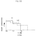
- the break strength of the tear portion can be controlled with a combination of a keep pressure and a core back timing at about the time filling is completed and the thickness near the tear portion.
- the core back timing is set to after the filling is completed.
- the keep pressure after the filling is completed is decreased, separating into several stages, and the core back timing is set to after a second stage of the keep pressure.
- the first stage of the keep pressure can be reliably performed by setting the core back timing to after the second stage of the keep pressure, the weight, size and shape of the formed product can be stabilized, so that generation of deficiencies in the product can be reduced.
- a twentieth aspect of the present invention comprises: a tear portion formed in the air bag door portion; and push-up means for pushing up a portion at both sides or one side of the air bag door portion having therebetween a center portion of the tear portion when a bag body of the air bag is expanded, wherein a resin fluidizing boundary is set at a core back area for forming the tear portion, and a line of the tear portion can not be seen from a side of an outer appearance.
- the impact load from the bag body of the air bag is concentrated at the center portion of the tear portion when the bag body of the air bag is expanded, since the push-up means is provided.
- the resin fluidizing boundary is set at the core back area which is for forming the break portion when the air bag door portion is expanded, it is possible to decrease the break force of the break portion to a desired value, due to strength reduction which depends on the resin fluidizing boundary. As a result, it is possible to devise to reconcile expansion performance and the quality of the outer appearance (making invisible).
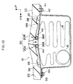
- FIG. 1 A first embodiment of a interior member for an automotive vehicle having an air bag door portion in accordance with the present invention will be described below with reference to Figs. 1 to 4.
- an arrow FR indicates a forward direction of an automotive vehicle
- an arrow UP indicates an upward direction an the automotive vehicle.
- an air bag apparatus 12 is arranged inside an assistant driver's seat.
- An air bag case 14 for this air bag apparatus 12 is fixed to an instrument panel reinforcement (not shown), and an inflator 16 and a air bag body 18 in a folded state is contained within the air bag case 14.
- a portion in a position substantially opposite to that of the air bag case 14 of the instrument panel 10 serves as an air bag door portion 20, and a portion other than the air bag door portion 20 of the instrument panel 10 serves as a main body portion 22.
- the air bag door portion 20 and the main body portion 22 are constituted of TSOP, which is a hard resin [obtained by making an elastomer (a rubber) and a PP (a polypropylene) Broy (a technique for making a high polymer multicomponent material of which can be expected a multiplier effect) and adding a talc so as to make it complex and strong, a PP that has a low specific gravity, impact resistance, rigidity and excellent fluidity is suitable for a thin product, and has, for example, a rate of a flexural modulus of elasticity of 1500 to 3000 Mpa], a PP resin, PC/ABS resin, a denatured PPO resin, a PC/PBT resin, an ABS resin, a PC resin, an ASG
- the air bag apparatus 12 is structured such that when a sudden deceleration of the automotive vehicle is detected by a mechanical or electrical acceleration sensor (not shown), the inflator 16 within the air bag case 14 is operates so as to expand the air bag body 18, contained within the air bag case 14 in a folded state, toward the air bag door portion 20 of the instrument panel 10.
- the air bag body 18 is structured such as to press the air bag door portion 20 in the instrument panel 10 so as to break and open the air bag door portion 20, thereby expanding within the vehicle cabin.
- a conventionally known popular structure can be applied to the air bag apparatus 12
- detailed descriptions of the air bag apparatus 12 will be omitted in this embodiment.
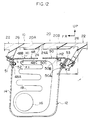
- a tear portion 24 which was made thin is formed in a center portion in a longitudinal direction and both end portions in a lateral direction of the air bag door portion 20 so as to be formed in an H shape, and it is structured such that the air bag door portion 20 is opened toward both directions in a longitudinal direction when the bag body of the air bag is expanded, so that the bag body of the air bag is expanded within the vehicle cabin.
- a cross section of the tear portion 24 of the air bag door portion 20 is formed in a V shape.
- protrusions 28 and 30 serving as push-up means is provided at positions at two sides in a longitudinal direction of the automotive vehicle having therebetween a center portion 24A of the tear portion 24 so as to protrude downward, and the protrusions 28 and 30 are integrally formed with the air bag door portion 20. Accordingly, it is structured such that when the bag body of the air bag is expanded, the expanding bag body of the air bag abuts lower surfaces 28A and 30A of the protrusions 28 and 30, thereby pressing the protrusions 28 and 30 upward (in a direction of an arrow A in Fig. 2).
- the protrusions 28 and 30 are formed in a lattice form by a narrow rib 32 extending in a longitudinal direction of the automotive vehicle and a narrow rib 34 extending in a lateral direction of the automotive vehicle.
- a width T1 of these ribs 32 and 34 is set to be equal to or less than half a thickness T of the air bag door portion 20 shown in Fig. 2, so that shrinkage is prevented.
- a width W1 and a length L1 of the protrusions 28 and 30 are respectively set to be about 5 to 20 % a total width W and a total length L of a front door portion 20A and a rear door portion 20B of the air bag door portion 20 shown in Fig. 3. Accordingly, the air bag door portion 20 is structured such that deflections in the lateral direction and the longitudinal direction are not significantly hampered by the protrusions 28 and 30, and the air bag door portion 20 is deflected in the lateral direction and the longitudinal direction when the bag body of the air bag is expanded, thereby being securely broken from the center portion 24A of the tear portion 24.
- a hinge portion 26 which has been made thin is formed at both end portions in the longitudinal direction of the air bag door portion 20.
- the air bag door portion 20 is structured such that when it is pressed by the expanding air bag body 18 when the air bag is expanded, it is opened and broken along the tear portion 24, so that the opened and broken front door portion 20A and rear door portion 20B rotate around the hinge portions 26 and an opening for expanding the air bag body 18 within the vehicle cabin is formed.
- each of corner portions 28B, 30B, 28C, 30C, 28D, 30D, 29E and 30E of the protrusions 28 and 30 abutting the air bag body 18 when the bag body of the air bag is expanded, is beveled, thereby protecting the air bag body 18.
- the air bag door portion 20 can be constituted of a hard material having a high rigidity, an oil-can-lake-feeling and deformation can be prevented. Furthermore, it is possible to devise to reconcile the quality of the outer appearance and expansion performance through a simple structure in which the protrusions 28 and 30 are merely provided in the air bag door portion 20.
- the protrusions 28 and 30 are formed by the ribs 32 and 34 integrally formed with the air bag door portion 20, the protrusions 28 and 30 can be formed without mounting a separate part, and since the width (T1) between the ribs 32 and 34 is narrower than the thickness (T) of the normal portion of the air bag door portion 20 (T1 ⁇ T/2), generation of shrinkage on the surface of the air bag door portion 20 caused by the ribs 32 and 34 after injection molding can be restricted, so that the quality of the outer appearance is not deteriorated.
- the protrusions 28 and 30 are formed in a lattice form by the narrow rib 32 extending in the longitudinal direction and the narrow rib 34 extending in the lateral direction; however, the shape of the protrusions 28 and 30 is not limited to this, for example, another shape such as an E shape or the like may be employed as shown in Fig. 5.
- the tea portion 24 is formed in an H shape in a plan view, however, the shape of the tear portion 24 is not limited to this, for example, a linear shape as shown in Fig. 6A, a double-Y shape as shown in Fig. 6B, an X shape as shown in Fig. 6C and the like may be employed. Still further, as shown in Fig. 6D, in a case wherein the tear portion 24 is formed in an X shape, the portions 29 and 31 may be formed by closing in the tear portion 24 in the lateral direction as well. Furthermore, as shown in Fig. 6E, in a case wherein the tear portion 24 is formed in a C shape, it is possible to form only the portion 28, at one side of the tear portion 24.
- metal plates 36 and 38 made of a metal, for example, aluminum, iron, stainless steel or the like, are respectively disposed below the front door portion 20A and the rear door portion 20B of the air bag door portion 20.
- a front end portion 36A of the metal plate 36 is fastened to both the air bag case 14 and the main body portion 22 of the instrument panel 10 by a bolt 40 passing through a mounting hole 39 punched into the metal plate 36.
- a rear end portion 38A of the metal plate 38 is fastened to both the air bag case 14 and the main body portion 22 of the instrument panel 10 by a bolt 42 passing through a mounting hole 41 punched into the metal plate 38.
- the air bag door portion 20 is structured such that deflections in the lateral direction and the longitudinal direction are not significantly hampered by the protrusions 28 and 30, and the air bag door portion 20 is deflected in the lateral direction and the longitudinal direction when the bag body of the air bag is expanded, thereby being securely broken from the center portion 24A of the tear portion 24.
- the portions 44 and 46 are formed at the lower side of the metal plates 36 and 38, that is, at the side of the air bag body 18; however, alternatively, as shown in Fig. 10, the portions 44 and 46 may be formed at the side of the upper surface of the metal plates 36 and 38, that is, at the side of the air bag door portion 20. In this case, by providing the portions 44 and 46 at the upper surface of the distal ends 36B and 38B of the metal plates 36 and 38, as shown in Fig.
- the same thinking can be applied. That is, after fluidization, in a state wherein solidification has began to occur, a control is performed with respect to the bonding portion (the melting portion) of the fluidizing resin, replacing the keep pressure which is the pressure within the mold relating to the surface pressure transmitted to the melting surface, with the core back timing and the thickness in the periphery of the tear, relating to the resin temperature (at which the resin of the melting surface portion is cooled from the melting state in accordance with the time passed) of the melting surface.
- the present invention has been explained in detail with respect to the specified embodiments; however, the present invention is not limited to the embodiments mentioned above, and it is obvious for those skilled in the art to modify the embodiments to the other various kinds of embodiments within the scope of the present invention.
- the cross-sectional shape of the tear portion 24 may be made into other shapes such as a U shape or the like in addition to the V shape.
- the present invention can be applied to a door trim, a center pillar, a garnish, a handle and the like in addition to the instrument panel.
- the time that the resin of the front door portion 20A injected from the gate G1 reaches the distal end 140 of the slide core 140 and the time T4 that the resin of the rear door portion 20B injected from the gate G2 reaches the distal end 140 of the slide core 140 are made about the same, by making the injection start time T2 for the gate G1 and the injection start time T1 for the gate G2 the same.
- an area at which the slide core 140 is provided is the area which satisfies the expansion performance and is allowed by the mold structure, and may be the whole area of the H-shaped thin portion 24 as shown in Fig. 29A; however, as shown in Fig. 29B, the area of the slide core 140 may be set to be only the area along the lateral line of the H-shaped thin portion 24. Further, as shown in Fig. 29C, the area of the slide core 140 may be set to be only the area along the vertical line of the H-shaped thin portion 24. Moreover, as shown in Figs. 29D to 29G, the area of the slide core 140 may be set to be only an extreme one portion of the H-shaped thin portion 24.
- the forming method in accordance with the eighth embodiment can be applied to an instrument panel 164 having an air bag door portion in which a main body portion 160 and an air bag door portion 162 are integrally formed by coinjection molding which depends on a slide core 163, using different resins for the main body portion 160 and the air bag door portion 162 of the instrument panel, as shown in Fig. 31.
- the skin 62 indicated here in a case of the skin insert, in addition to the skin 62 having a single layer as shown in Fig. 17A, the skin 62 having two layers as shown in Fig. 17B and the skin 62 having three layers as shown in Fig. 17C may be used.
- the tear portion 64 formed on the skin 62 as shown in Figs. 34 and 35 may be formed from the reverse face side as well as from the obverse face side.
- the shape of the tear portion 64 is not limited to a U-shaped groove cross section, but may be other shapes such as a V-shaped groove cross section, a slit shape or the like.
- the trim member for the automotive vehicle having the air bag door portion in accordance with the present invention and the method of forming the same are useful for forming the air bag door portion of the trim member for the automotive vehicle and the main body portion of the trim member for the automotive vehicle by the same resin, and are particularly suitable for decreasing the break force of the break portion of the air bag door portion to a desired value without reducing the quality of the outer appearance.
Landscapes
- Engineering & Computer Science (AREA)
- Mechanical Engineering (AREA)
- Manufacturing & Machinery (AREA)
- Air Bags (AREA)
- Vehicle Interior And Exterior Ornaments, Soundproofing, And Insulation (AREA)
Priority Applications (1)
| Application Number | Priority Date | Filing Date | Title |
|---|---|---|---|
| EP07020983A EP1882616B1 (de) | 1997-03-26 | 1998-03-20 | Kraftfahrzeuginnenverkleidung mit einer Airbagabdeckklappe, und Giessverfahren derselben. |
Applications Claiming Priority (7)
| Application Number | Priority Date | Filing Date | Title |
|---|---|---|---|
| JP73702/97 | 1997-03-26 | ||
| JP7370297 | 1997-03-26 | ||
| JP203237/97 | 1997-07-29 | ||
| JP20323797A JP3765166B2 (ja) | 1997-07-29 | 1997-07-29 | エアバッグドア部を有する車両用内装部材 |
| JP305357/97 | 1997-11-07 | ||
| JP30535797A JP3428402B2 (ja) | 1997-03-26 | 1997-11-07 | エアバッグドア部を有する車両用内装部材及びその成形方法 |
| PCT/JP1998/001207 WO1998042547A1 (fr) | 1997-03-26 | 1998-03-20 | Element interieur comportant une section de porte d'airbag destine a etre utilise dans des vehicules, et son procede de moulage |
Related Child Applications (1)
| Application Number | Title | Priority Date | Filing Date |
|---|---|---|---|
| EP07020983A Division EP1882616B1 (de) | 1997-03-26 | 1998-03-20 | Kraftfahrzeuginnenverkleidung mit einer Airbagabdeckklappe, und Giessverfahren derselben. |
Publications (3)
| Publication Number | Publication Date |
|---|---|
| EP0904994A1 true EP0904994A1 (de) | 1999-03-31 |
| EP0904994A4 EP0904994A4 (de) | 2001-06-06 |
| EP0904994B1 EP0904994B1 (de) | 2009-05-13 |
Family
ID=27301289
Family Applications (2)
| Application Number | Title | Priority Date | Filing Date |
|---|---|---|---|
| EP07020983A Expired - Lifetime EP1882616B1 (de) | 1997-03-26 | 1998-03-20 | Kraftfahrzeuginnenverkleidung mit einer Airbagabdeckklappe, und Giessverfahren derselben. |
| EP98909787A Expired - Lifetime EP0904994B1 (de) | 1997-03-26 | 1998-03-20 | Innenfahrzeugteile mit einer airbagaustrittsklappe und giessmethode dafür |
Family Applications Before (1)
| Application Number | Title | Priority Date | Filing Date |
|---|---|---|---|
| EP07020983A Expired - Lifetime EP1882616B1 (de) | 1997-03-26 | 1998-03-20 | Kraftfahrzeuginnenverkleidung mit einer Airbagabdeckklappe, und Giessverfahren derselben. |
Country Status (8)
| Country | Link |
|---|---|
| US (3) | US6612607B1 (de) |
| EP (2) | EP1882616B1 (de) |
| KR (1) | KR100307105B1 (de) |
| CN (1) | CN100374328C (de) |
| CA (1) | CA2256497C (de) |
| DE (2) | DE69840821D1 (de) |
| ES (1) | ES2324321T3 (de) |
| WO (1) | WO1998042547A1 (de) |
Cited By (8)
| Publication number | Priority date | Publication date | Assignee | Title |
|---|---|---|---|---|
| US6502851B2 (en) * | 2000-05-11 | 2003-01-07 | Takata Corporation | Attachment structure of passenger side airbag device |
| EP1328424A1 (de) * | 2000-10-27 | 2003-07-23 | Textron Automotive Company Inc. | Airbagabdeckanordnung |
| EP1074434B1 (de) * | 1999-08-06 | 2005-04-20 | TRW Automotive Safety Systems GmbH | Abdeckung für einen Gassack eines Fahrzeuginsassen-Rückhaltesystems |
| FR2862587A1 (fr) * | 2003-11-24 | 2005-05-27 | Faurecia Interieur Ind | Piece d'equipement interieur de vehicule automobile, notamment planche de bord, dotee d'un dispositif de securite a sac gonflable a moyens de fixation ameliores |
| DE10160185B4 (de) * | 2001-12-07 | 2007-01-18 | Lisa Dräxlmaier GmbH | Verfahren zum Erzeugen einer Befestigungsstruktur für ein Airbagmodul und Innenverkleidungsteilträger |
| DE102008055010A1 (de) | 2007-12-20 | 2009-06-25 | Volkswagen Ag | Innenverkleidungsteil, insbesondere Instrumententafel für ein Kraftfahrzeug, Verfahren zur Herstellung eines Innenverkleidungsteiles und Fahrzeug, insbesondere Kraftfahrzeug, welches ein Innenverkleidungsteil aufweist |
| EP3045305A1 (de) * | 2013-09-13 | 2016-07-20 | Toyoda Iron Works Co., Ltd. | Mehrschichtige zusammengesetzte innenausstattungskomponente |
| EP3116698B1 (de) * | 2014-03-14 | 2019-08-14 | EuWe Eugen Wexler Holding GmbH & Co. KG | Verfahren zur herstellung eines kunststoffbauteils mittels eines spritzgiessprozesses |
Families Citing this family (55)
| Publication number | Priority date | Publication date | Assignee | Title |
|---|---|---|---|---|
| DE10127509A1 (de) * | 2001-06-06 | 2003-01-09 | Volkswagen Ag | Gehäuse für ein Airbagmodul |
| CN1582237A (zh) * | 2001-10-23 | 2005-02-16 | 通用电气公司 | 带有隐藏的气囊门的仪表板系统 |
| WO2004026629A2 (en) * | 2002-09-17 | 2004-04-01 | Collins & Aikman Products Co. | Ultrasonic blade design for scoring double angle groove and products therefrom |
| JP4337340B2 (ja) * | 2002-12-12 | 2009-09-30 | タカタ株式会社 | エアバッグ装置 |
| US20040256879A1 (en) * | 2003-06-20 | 2004-12-23 | Jsp Licenses, Inc. | Instrument panel and method of making same |
| FR2857923B1 (fr) * | 2003-07-23 | 2006-01-27 | Faurecia Interieur Ind | Planche de bord comportant une trappe retenue par des pontets |
| JP2005067466A (ja) * | 2003-08-26 | 2005-03-17 | Takata Corp | 乗員脚部保護装置 |
| DE20313367U1 (de) * | 2003-08-28 | 2004-01-08 | Trw Automotive Safety Systems Gmbh | Gassackmodul für ein Fahrzeuginsassen-Schutzsystem |
| DE502004003708D1 (de) * | 2003-09-03 | 2007-06-14 | Autoliv Dev | Gehäuse für eine airbagvorrichtung |
| DE10345026B4 (de) * | 2003-09-24 | 2007-07-19 | Faurecia Innenraum Systeme Gmbh | Innenverkleidungsteil zur Abdeckung eines Airbags |
| KR100520551B1 (ko) * | 2003-10-10 | 2005-10-11 | 현대자동차주식회사 | 인비져블 에어백용 피에이비 도어 설계 방법 |
| JP4640726B2 (ja) * | 2004-08-06 | 2011-03-02 | タカタ株式会社 | エアバッグカバーの製造方法 |
| US7687003B2 (en) * | 2004-12-08 | 2010-03-30 | Visteon Global Technologies, Inc. | Method of forming plastic part having hidden thin walled section |
| WO2006065750A1 (en) * | 2004-12-14 | 2006-06-22 | Johnson Controls Technology Company | Air bag cover |
| US7434829B2 (en) * | 2005-04-22 | 2008-10-14 | Visteon Global Technologies, Inc. | Interior panel having airbag deployment door |
| JP4831999B2 (ja) * | 2005-05-31 | 2011-12-07 | 三光合成株式会社 | 車両用エアーバック装置及びエアーバックカバー |
| JP4820473B2 (ja) | 2005-06-21 | 2011-11-24 | 日本プラスト株式会社 | 自動車用内装パネル |
| US20070057498A1 (en) * | 2005-09-12 | 2007-03-15 | Hyundai Mobis Co., Ltd. | Airbag device |
| US7299688B2 (en) * | 2005-11-02 | 2007-11-27 | Salvisberg Marc W | Device and method for maximizing internal combustion engine horsepower for a preselected RPM range |
| JP4746980B2 (ja) * | 2005-12-19 | 2011-08-10 | タカタ株式会社 | エアバッグ装置 |
| FR2897577B1 (fr) * | 2006-02-22 | 2013-08-02 | Demo Injection | Couvercle de coussin gonflable a rupture facile |
| JP4854325B2 (ja) * | 2006-02-24 | 2012-01-18 | 株式会社イノアックコーポレーション | エアバッグドアおよびその製造方法 |
| EP1857333A3 (de) * | 2006-05-19 | 2008-06-25 | Illinois Tool Works Inc. | Befestigung für einen Vorhangairbag |
| DE202006013133U1 (de) * | 2006-08-23 | 2006-11-02 | Takata-Petri Ag | Gassackabdeckung |
| KR100812835B1 (ko) * | 2006-12-06 | 2008-03-11 | 현대자동차주식회사 | 차량용 조수석 에어백 및 그 제조방법 |
| FR2916175B1 (fr) * | 2007-05-16 | 2009-11-27 | Faurecia Interieur Ind | Element d'habillage de l'interieur d'un vehicule automobile. |
| US20080315566A1 (en) * | 2007-06-20 | 2008-12-25 | Andrasik Iii Joseph | Instrument panel with integral hidden door cover and method of manufacture thereof |
| EP2006165B1 (de) * | 2007-06-21 | 2012-09-05 | SMP Deutschland GmbH | Innenraumverkleidung mit integrierter Airbagabdeckung für ein Kraftfahrzeug sowie ein Verfahren zu ihrer Herstellung |
| JP5151342B2 (ja) * | 2007-09-18 | 2013-02-27 | トヨタ自動車株式会社 | 車両用ニーエアバッグ装置 |
| JP4954916B2 (ja) * | 2008-02-06 | 2012-06-20 | タカタ株式会社 | エアバッグカバー、インストルメントパネル、エアバッグ装置、エアバッグ収容体 |
| US20100038891A1 (en) * | 2008-08-12 | 2010-02-18 | Bryan Welch | Instrument panel for motor vehicle |
| KR101013911B1 (ko) * | 2008-10-08 | 2011-02-14 | 기아자동차주식회사 | 차량 내장용 크래쉬 패드 및 그 제조장치 |
| US8157311B2 (en) * | 2010-03-11 | 2012-04-17 | Ford Global Technologies, Llc | Vehicular trim panel with storage and interfacing of electronic devices |
| JP5777057B2 (ja) * | 2011-06-29 | 2015-09-09 | 日本プラスト株式会社 | エアバッグカバー |
| US8336908B1 (en) * | 2011-08-08 | 2012-12-25 | Ford Global Technologies, Llc | Insert molded TPO chute for automotive air bag system |
| US9010799B2 (en) * | 2012-03-21 | 2015-04-21 | Faurecia Interior Systems, Inc. | Molding in airbag door features in a vehicle interior panel using a movable mold member |
| US8567816B1 (en) * | 2012-12-19 | 2013-10-29 | Faurecia Interior Systems, Inc. | Airbag tear seam shapes |
| FR3000449B1 (fr) * | 2012-12-27 | 2016-02-05 | Faurecia Interieur Ind | Piece d'habillage interieur de vehicule adaptee pour recouvrir un coussin de securite gonflable |
| KR20140115654A (ko) * | 2013-03-21 | 2014-10-01 | 현대모비스 주식회사 | 자동차 에어백 |
| US8870219B1 (en) * | 2013-08-02 | 2014-10-28 | Faurecia Interior Systems, Inc. | Foam-in-place interior panels having integrated airbag doors including substrates with airbag chute-door assemblies for motor vehicles |
| CN105473387B (zh) | 2013-08-23 | 2017-08-04 | 本田技研工业株式会社 | 安全气囊装置 |
| JP2015093555A (ja) * | 2013-11-11 | 2015-05-18 | 豊田合成株式会社 | 車両用内装パネル及び車両用エアバッグ装置 |
| DE202016105511U1 (de) * | 2016-10-05 | 2017-01-30 | Lear Corporation | Airbagsystem für ein Fahrzeug |
| CN105774733B (zh) * | 2016-04-19 | 2018-04-10 | 芜湖金鹏汽车部件有限公司 | 一种安全气囊用防刺破防护装置安装支架 |
| US11034319B2 (en) * | 2016-06-10 | 2021-06-15 | Key Safety Systems, Inc. | Air bag module |
| CN109803691A (zh) | 2016-06-16 | 2019-05-24 | 安斯百克特生物系统公司 | 生物打印的半月板植入物及其使用方法 |
| JP6879137B2 (ja) * | 2017-09-08 | 2021-06-02 | トヨタ自動車株式会社 | 後席サイドエアバッグ装置 |
| US10377336B2 (en) * | 2017-11-13 | 2019-08-13 | Ford Global Technologies, Llc | Molded air bag chute with door reinforced by hollow channel |
| EP3727484A1 (de) | 2017-12-20 | 2020-10-28 | Aspect Biosystems Ltd. | Biogedrucktes meniskusimplantat und verfahren zur verwendung davon |
| KR20210006643A (ko) * | 2019-07-09 | 2021-01-19 | 현대자동차주식회사 | 에어백 도어 전개부를 포함하는 크러쉬 패드 |
| DE102019126901A1 (de) * | 2019-10-07 | 2021-04-08 | StreetScooter GmbH | Airbagklappensystem mit Randvertiefungen unterschiedlicher Materialstärke |
| KR102572301B1 (ko) | 2021-01-25 | 2023-08-30 | 현대모비스 주식회사 | Pab 도어의 절개 유도 장치 및 그 제조방법 |
| WO2022187164A1 (en) * | 2021-03-01 | 2022-09-09 | Yanfeng Global Automotive Interior Systems Co. Ltd | Component for vehicle interior |
| US11603072B2 (en) * | 2021-08-06 | 2023-03-14 | Autoliv Asp, Inc. | Dual stage inflator |
| US20240034262A1 (en) * | 2022-07-29 | 2024-02-01 | Nissan North America, Inc. | Instrument panel airbag assembly |
Citations (5)
| Publication number | Priority date | Publication date | Assignee | Title |
|---|---|---|---|---|
| US5375876A (en) * | 1993-10-05 | 1994-12-27 | Tip Engineering Group, Inc. | Air bag deployment door installation |
| EP0639481A1 (de) * | 1993-08-18 | 1995-02-22 | Tip Engineering Group, Inc. | Verfahren und Behandlung zur Herstellung einer Luftsack-Entfaltungsöffnung in einer mit Leder bedeckten Verkleidung |
| DE4436130A1 (de) * | 1993-09-28 | 1995-03-30 | Kansei Kk | Harzerzeugnis, Airbagabdeckung und Verfahren zum Formen derselben |
| US5499842A (en) * | 1994-02-17 | 1996-03-19 | Toyoda Gosei Co., Ltd. | Pad for air bag device |
| JPH0952567A (ja) * | 1995-08-11 | 1997-02-25 | Toyota Motor Corp | エアバッグドアを備えたインストルメントパネル |
Family Cites Families (60)
| Publication number | Priority date | Publication date | Assignee | Title |
|---|---|---|---|---|
| US548361A (en) * | 1895-10-22 | Thomas gray | ||
| US561564A (en) * | 1896-06-09 | George carlyle | ||
| US4895389A (en) * | 1988-08-31 | 1990-01-23 | E. I. Dupont De Nemours And Company | Rupturable cover for a vehicle air bag compartment |
| US4989896A (en) * | 1988-10-17 | 1991-02-05 | Tip Engineering Group, Inc. | Double door closure for an air bag deployment opening |
| JPH02109848A (ja) * | 1988-10-17 | 1990-04-23 | Showa Denko Kk | プラスチック製易開封性蓋およびその製造方法 |
| JPH0451076Y2 (de) | 1988-10-28 | 1992-12-02 | ||
| JPH02303949A (ja) | 1989-05-17 | 1990-12-17 | Nippon Plast Co Ltd | エアバックのカバー体 |
| US5135253A (en) | 1989-05-24 | 1992-08-04 | Mazda Motor Corporation | Air bag system for vehicle |
| JPH02149346U (de) | 1989-05-24 | 1990-12-19 | ||
| US5082310A (en) | 1989-11-06 | 1992-01-21 | Tip Engineering Group, Inc. | Arrangement for providing an air bag deployment opening |
| JP2507843Y2 (ja) | 1990-02-23 | 1996-08-21 | マツダ株式会社 | 自動車のエアバッグ取付構造 |
| JPH03254919A (ja) | 1990-03-06 | 1991-11-13 | Takata Kk | エアバッグのモジュールカバーの製造方法 |
| JPH03279055A (ja) | 1990-03-28 | 1991-12-10 | Mazda Motor Corp | 自動車のエアバッグ装置 |
| JPH03281547A (ja) | 1990-03-29 | 1991-12-12 | Toyo Tire & Rubber Co Ltd | ゴム配合組成物 |
| JP2959865B2 (ja) | 1991-03-29 | 1999-10-06 | マツダ株式会社 | 自動車のエアバッグ構造 |
| JP3179544B2 (ja) | 1992-01-10 | 2001-06-25 | カルソニックカンセイ株式会社 | インストルメントパネル |
| JPH061016U (ja) | 1992-06-15 | 1994-01-11 | 株式会社東海理化電機製作所 | エアバッグ装置用カバー |
| JP3354595B2 (ja) | 1992-07-15 | 2002-12-09 | セイコープレシジョン株式会社 | カメラ用情報入力装置 |
| US5456490A (en) * | 1992-08-13 | 1995-10-10 | Davidson Textron Inc. | Hidden door for an air bag restraint system |
| US5390950A (en) * | 1993-03-04 | 1995-02-21 | Tip Eng Group Inc | Method and arrangement for forming an air bag deployment opening in an auto interior trim piece |
| US5458361A (en) * | 1993-08-25 | 1995-10-17 | Davidson Textron Inc. | Insert for air bag cover assembly |
| US5393089A (en) | 1993-09-01 | 1995-02-28 | Chrysler Corporation | Vehicle air bag cover |
| JPH0740429U (ja) | 1993-12-20 | 1995-07-18 | 内藤工業株式会社 | ヒンジ部構造 |
| US5439246A (en) | 1994-02-07 | 1995-08-08 | Morton Internatinal, Inc. | Multi-directional air bag module door attachment |
| JP3337821B2 (ja) | 1994-04-28 | 2002-10-28 | 株式会社イノアックコーポレーション | インストルメントパネルのエアバッグ部の構造 |
| US5447327A (en) | 1994-05-25 | 1995-09-05 | Morton International, Inc. | Arrangement for providing an air bag deployment opening |
| JP3453195B2 (ja) * | 1994-07-08 | 2003-10-06 | 三菱重工業株式会社 | 射出成形方法 |
| US5590901A (en) * | 1994-09-14 | 1997-01-07 | The Goodyear Tire & Rubber Company | Method and apparatus for vehicle trim panel having hidden air bag door |
| JP3439847B2 (ja) | 1994-09-16 | 2003-08-25 | 株式会社イノアックコーポレーション | 自動車用エアバッグドアの構造 |
| JPH08164814A (ja) | 1994-10-13 | 1996-06-25 | Sensor Technol Kk | バッグカバー |
| US5536037A (en) * | 1994-11-18 | 1996-07-16 | Trw Vehicle Safety Systems Inc. | Deployment door for use in a vehicle occupant restraint apparatus |
| JPH08192666A (ja) * | 1995-01-20 | 1996-07-30 | Toyo Tire & Rubber Co Ltd | インストルメントパネル |
| JPH08216216A (ja) | 1995-02-16 | 1996-08-27 | Kawamura Kako Kk | 破断用溝部を有するプラスチック品の成形方法 |
| US5564731A (en) | 1995-03-31 | 1996-10-15 | Davidson Textron Inc. | Motor vehicle instrument panel with flexible tethering hinged air bag deployment door |
| JPH08268205A (ja) | 1995-03-31 | 1996-10-15 | Toyoda Gosei Co Ltd | パッドの製造方法 |
| JP3418809B2 (ja) | 1995-04-17 | 2003-06-23 | 東洋ゴム工業株式会社 | エアバッグ用インストルメントパネルの表皮およびその成形方法 |
| JP3466322B2 (ja) | 1995-04-24 | 2003-11-10 | カルソニックカンセイ株式会社 | 車両用エアバッグカバー及びその成形方法 |
| EP0748722B1 (de) * | 1995-06-16 | 2001-09-12 | Toyoda Gosei Co., Ltd. | Innenverkleidungsteil für ein Kraftfahrzeug mit einem Luftsack und Herstellungsverfahren dafür |
| JP3473185B2 (ja) | 1995-06-16 | 2003-12-02 | 豊田合成株式会社 | エアバッグ装置用内装部材 |
| JP3111855B2 (ja) | 1995-06-16 | 2000-11-27 | 豊田合成株式会社 | エアバッグ装置用内装部材 |
| JP3254973B2 (ja) | 1995-07-31 | 2002-02-12 | 豊田合成株式会社 | エアバッグカバー |
| JPH092180A (ja) | 1995-06-21 | 1997-01-07 | Toyoda Gosei Co Ltd | エアバッグカバー |
| JP3304693B2 (ja) | 1995-06-21 | 2002-07-22 | 豊田合成株式会社 | エアバッグカバーの製造方法 |
| JPH092181A (ja) | 1995-06-21 | 1997-01-07 | Toyoda Gosei Co Ltd | エアバッグカバー |
| JP3227638B2 (ja) | 1995-08-11 | 2001-11-12 | 豊田合成株式会社 | エアバッグカバー |
| US5698283A (en) * | 1995-06-21 | 1997-12-16 | Toyoda Gosei Co., Ltd. | Air bag cover and manufacturing method for same |
| JP3728778B2 (ja) * | 1995-09-22 | 2005-12-21 | 豊田合成株式会社 | エアバッグカバー |
| US5590903A (en) * | 1995-09-29 | 1997-01-07 | Trw Vehicle Safety Systems, Inc. | Deployment door assembly |
| US5580083A (en) * | 1995-10-02 | 1996-12-03 | Davidson Textron Inc. | Air bag cover with seamless interface tear seam and method and apparatus for producing same |
| DE19538871A1 (de) * | 1995-10-19 | 1997-04-24 | Mst Automotive Gmbh | Airbag-Gehäuse |
| JPH09156445A (ja) * | 1995-12-12 | 1997-06-17 | Toyoda Gosei Co Ltd | エアバッグカバー |
| JP3326481B2 (ja) * | 1996-04-30 | 2002-09-24 | 住友化学工業株式会社 | エアーバッグカバー一体成形車両内装部品 |
| US5755459A (en) * | 1996-06-18 | 1998-05-26 | Trw Vehicle Safety Systems Inc. | Folded air bag with adhesive |
| DE19626416A1 (de) * | 1996-07-01 | 1998-01-08 | Takata Europ Gmbh | Airbagmodul-Abdeckkappe |
| JP3759262B2 (ja) * | 1996-11-26 | 2006-03-22 | 日産自動車株式会社 | エアバック |
| AU749401B2 (en) * | 1997-02-19 | 2002-06-27 | Toyo Tire & Rubber Co., Ltd. | Instrument panel for air bag |
| JP3793790B2 (ja) * | 1997-04-11 | 2006-07-05 | カルソニックカンセイ株式会社 | 車両用エアバッグ装置 |
| US5941558A (en) * | 1997-06-09 | 1999-08-24 | Textron Automotive Company Inc. | Apparatus for deploying an airbag through a hard panel |
| US6042140A (en) * | 1998-07-10 | 2000-03-28 | Larry J. Winget | Air bag cover having a visually perceptible tear seam |
| JP2001088646A (ja) * | 1999-09-22 | 2001-04-03 | Mitsuboshi Belting Ltd | エアバッグドア構造 |
-
1998
- 1998-03-20 EP EP07020983A patent/EP1882616B1/de not_active Expired - Lifetime
- 1998-03-20 CA CA002256497A patent/CA2256497C/en not_active Expired - Fee Related
- 1998-03-20 KR KR1019980709553A patent/KR100307105B1/ko not_active IP Right Cessation
- 1998-03-20 EP EP98909787A patent/EP0904994B1/de not_active Expired - Lifetime
- 1998-03-20 CN CNB988003678A patent/CN100374328C/zh not_active Expired - Fee Related
- 1998-03-20 DE DE69840821T patent/DE69840821D1/de not_active Expired - Lifetime
- 1998-03-20 WO PCT/JP1998/001207 patent/WO1998042547A1/ja active IP Right Grant
- 1998-03-20 DE DE69842246T patent/DE69842246D1/de not_active Expired - Lifetime
- 1998-03-20 ES ES98909787T patent/ES2324321T3/es not_active Expired - Lifetime
- 1998-03-20 US US09/194,355 patent/US6612607B1/en not_active Expired - Fee Related
-
2003
- 2003-03-26 US US10/396,554 patent/US6733713B2/en not_active Expired - Fee Related
-
2004
- 2004-01-09 US US10/753,358 patent/US7063349B2/en not_active Expired - Fee Related
Patent Citations (5)
| Publication number | Priority date | Publication date | Assignee | Title |
|---|---|---|---|---|
| EP0639481A1 (de) * | 1993-08-18 | 1995-02-22 | Tip Engineering Group, Inc. | Verfahren und Behandlung zur Herstellung einer Luftsack-Entfaltungsöffnung in einer mit Leder bedeckten Verkleidung |
| DE4436130A1 (de) * | 1993-09-28 | 1995-03-30 | Kansei Kk | Harzerzeugnis, Airbagabdeckung und Verfahren zum Formen derselben |
| US5375876A (en) * | 1993-10-05 | 1994-12-27 | Tip Engineering Group, Inc. | Air bag deployment door installation |
| US5499842A (en) * | 1994-02-17 | 1996-03-19 | Toyoda Gosei Co., Ltd. | Pad for air bag device |
| JPH0952567A (ja) * | 1995-08-11 | 1997-02-25 | Toyota Motor Corp | エアバッグドアを備えたインストルメントパネル |
Non-Patent Citations (2)
| Title |
|---|
| PATENT ABSTRACTS OF JAPAN vol. 1997, no. 06, 30 June 1997 (1997-06-30) & JP 09 052567 A (TOYOTA MOTOR CORP), 25 February 1997 (1997-02-25) * |
| See also references of WO9842547A1 * |
Cited By (13)
| Publication number | Priority date | Publication date | Assignee | Title |
|---|---|---|---|---|
| EP1074434B1 (de) * | 1999-08-06 | 2005-04-20 | TRW Automotive Safety Systems GmbH | Abdeckung für einen Gassack eines Fahrzeuginsassen-Rückhaltesystems |
| US6502851B2 (en) * | 2000-05-11 | 2003-01-07 | Takata Corporation | Attachment structure of passenger side airbag device |
| EP1328424A4 (de) * | 2000-10-27 | 2005-08-17 | Textron Automotive Co Inc | Airbagabdeckanordnung |
| EP1328424A1 (de) * | 2000-10-27 | 2003-07-23 | Textron Automotive Company Inc. | Airbagabdeckanordnung |
| DE10160185B4 (de) * | 2001-12-07 | 2007-01-18 | Lisa Dräxlmaier GmbH | Verfahren zum Erzeugen einer Befestigungsstruktur für ein Airbagmodul und Innenverkleidungsteilträger |
| FR2862587A1 (fr) * | 2003-11-24 | 2005-05-27 | Faurecia Interieur Ind | Piece d'equipement interieur de vehicule automobile, notamment planche de bord, dotee d'un dispositif de securite a sac gonflable a moyens de fixation ameliores |
| WO2005051728A1 (fr) * | 2003-11-24 | 2005-06-09 | Faurecia Interieur Industrie | Piece d'equipement interieur de vehicule automobile, notamment planche de bord, dotee d'un dispositif de securite a sac gonflable a moyens de fixation ameliores |
| DE102008055010A1 (de) | 2007-12-20 | 2009-06-25 | Volkswagen Ag | Innenverkleidungsteil, insbesondere Instrumententafel für ein Kraftfahrzeug, Verfahren zur Herstellung eines Innenverkleidungsteiles und Fahrzeug, insbesondere Kraftfahrzeug, welches ein Innenverkleidungsteil aufweist |
| DE102008055010B4 (de) | 2007-12-20 | 2022-07-07 | Volkswagen Ag | Innenverkleidungsteil, insbesondere Instrumententafel für ein Kraftfahrzeug, Verfahren zur Herstellung eines Innenverkleidungsteiles und Fahrzeug, insbesondere Kraftfahrzeug, welches ein Innenverkleidungsteil aufweist |
| EP3045305A1 (de) * | 2013-09-13 | 2016-07-20 | Toyoda Iron Works Co., Ltd. | Mehrschichtige zusammengesetzte innenausstattungskomponente |
| EP3045305A4 (de) * | 2013-09-13 | 2017-05-17 | Toyoda Iron Works Co., Ltd. | Mehrschichtige zusammengesetzte innenausstattungskomponente |
| EP3116698B1 (de) * | 2014-03-14 | 2019-08-14 | EuWe Eugen Wexler Holding GmbH & Co. KG | Verfahren zur herstellung eines kunststoffbauteils mittels eines spritzgiessprozesses |
| US11192284B2 (en) | 2014-03-14 | 2021-12-07 | Euwe Eugen Wexler Holding Gmbh & Co. Kg | Method for producing a plastic component by means of an injection moulding process |
Also Published As
| Publication number | Publication date |
|---|---|
| CN100374328C (zh) | 2008-03-12 |
| KR100307105B1 (ko) | 2001-11-15 |
| EP0904994B1 (de) | 2009-05-13 |
| US6612607B1 (en) | 2003-09-02 |
| WO1998042547A1 (fr) | 1998-10-01 |
| US20040140652A1 (en) | 2004-07-22 |
| EP1882616A3 (de) | 2009-11-25 |
| KR20000015992A (ko) | 2000-03-25 |
| EP0904994A4 (de) | 2001-06-06 |
| US7063349B2 (en) | 2006-06-20 |
| CA2256497A1 (en) | 1998-10-01 |
| DE69842246D1 (de) | 2011-06-09 |
| US20030189321A1 (en) | 2003-10-09 |
| ES2324321T3 (es) | 2009-08-04 |
| CN1220637A (zh) | 1999-06-23 |
| DE69840821D1 (de) | 2009-06-25 |
| US6733713B2 (en) | 2004-05-11 |
| CA2256497C (en) | 2003-07-01 |
| EP1882616A2 (de) | 2008-01-30 |
| EP1882616B1 (de) | 2011-04-27 |
Similar Documents
| Publication | Publication Date | Title |
|---|---|---|
| EP1882616B1 (de) | Kraftfahrzeuginnenverkleidung mit einer Airbagabdeckklappe, und Giessverfahren derselben. | |
| US6899363B2 (en) | Method of forming a vehicle component | |
| JP3298503B2 (ja) | エアバッグドア部を有する車両用内装部材 | |
| EP1002703B1 (de) | Paneel für luftkissen und verfahren zu dessen herstellung | |
| US5762362A (en) | Automotive air bag cover and method of molding same | |
| EP1393990B1 (de) | Mit einem Luftsackdeckel ausgerüstete Fahrzeug-Innenverkleidung und Herstellungsverfahren dafür | |
| JP3765166B2 (ja) | エアバッグドア部を有する車両用内装部材 | |
| JP3430915B2 (ja) | エアバッグドア部を有する車両用内装部材 | |
| CN101186198B (zh) | 具有气囊门部分的车辆用内部构件及其成形方法 | |
| JP3428402B2 (ja) | エアバッグドア部を有する車両用内装部材及びその成形方法 | |
| JP4961293B2 (ja) | 樹脂成形品の振動溶着構造 | |
| JP2000127883A (ja) | 車両用エアバッグ装置のリッド部構造 | |
| EP4159551A1 (de) | Innenverkleidungsteil für ein fahrzeug, anordnung mit dem innenverkleidungsteil und einem airbagmodul und verfahren zur herstellung des innenverkleidungsteils | |
| JP4067355B2 (ja) | 自動車内装品本体 | |
| CN115891853A (zh) | 车用内饰件、包括内饰件和气囊模块的组件及制造内饰件的方法 | |
| JPH10291232A (ja) | エアバッグドア部を一体に有するインストルメントパネルの成形方法 | |
| JP2007022336A (ja) | エアバッグドア部付内装品 | |
| JP2004161017A (ja) | エアバッグドア部を有する車両用内装部材 | |
| JP2000071914A (ja) | 車両用エアバッグ装置のリッド構造 | |
| JP2000211464A (ja) | エアバッグドア部を一体に有する車両用内装部材 | |
| JP2001058524A (ja) | 自動車用インスツルメントパネルの緩衝構造 |
Legal Events
| Date | Code | Title | Description |
|---|---|---|---|
| PUAI | Public reference made under article 153(3) epc to a published international application that has entered the european phase |
Free format text: ORIGINAL CODE: 0009012 |
|
| 17P | Request for examination filed |
Effective date: 19981223 |
|
| AK | Designated contracting states |
Kind code of ref document: A1 Designated state(s): DE ES FR GB IT |
|
| A4 | Supplementary search report drawn up and despatched |
Effective date: 20010425 |
|
| AK | Designated contracting states |
Kind code of ref document: A4 Designated state(s): DE ES FR GB IT |
|
| 17Q | First examination report despatched |
Effective date: 20021217 |
|
| 17Q | First examination report despatched |
Effective date: 20021217 |
|
| GRAP | Despatch of communication of intention to grant a patent |
Free format text: ORIGINAL CODE: EPIDOSNIGR1 |
|
| GRAP | Despatch of communication of intention to grant a patent |
Free format text: ORIGINAL CODE: EPIDOSNIGR1 |
|
| GRAS | Grant fee paid |
Free format text: ORIGINAL CODE: EPIDOSNIGR3 |
|
| GRAA | (expected) grant |
Free format text: ORIGINAL CODE: 0009210 |
|
| AK | Designated contracting states |
Kind code of ref document: B1 Designated state(s): DE ES FR GB IT |
|
| REG | Reference to a national code |
Ref country code: GB Ref legal event code: FG4D |
|
| REF | Corresponds to: |
Ref document number: 69840821 Country of ref document: DE Date of ref document: 20090625 Kind code of ref document: P |
|
| REG | Reference to a national code |
Ref country code: ES Ref legal event code: FG2A Ref document number: 2324321 Country of ref document: ES Kind code of ref document: T3 |
|
| PLBE | No opposition filed within time limit |
Free format text: ORIGINAL CODE: 0009261 |
|
| STAA | Information on the status of an ep patent application or granted ep patent |
Free format text: STATUS: NO OPPOSITION FILED WITHIN TIME LIMIT |
|
| 26N | No opposition filed |
Effective date: 20100216 |
|
| PGFP | Annual fee paid to national office [announced via postgrant information from national office to epo] |
Ref country code: FR Payment date: 20120319 Year of fee payment: 15 |
|
| PGFP | Annual fee paid to national office [announced via postgrant information from national office to epo] |
Ref country code: IT Payment date: 20120317 Year of fee payment: 15 Ref country code: GB Payment date: 20120314 Year of fee payment: 15 |
|
| PGFP | Annual fee paid to national office [announced via postgrant information from national office to epo] |
Ref country code: DE Payment date: 20120411 Year of fee payment: 15 |
|
| PGFP | Annual fee paid to national office [announced via postgrant information from national office to epo] |
Ref country code: ES Payment date: 20120327 Year of fee payment: 15 |
|
| GBPC | Gb: european patent ceased through non-payment of renewal fee |
Effective date: 20130320 |
|
| REG | Reference to a national code |
Ref country code: FR Ref legal event code: ST Effective date: 20131129 |
|
| REG | Reference to a national code |
Ref country code: DE Ref legal event code: R119 Ref document number: 69840821 Country of ref document: DE Effective date: 20131001 |
|
| PG25 | Lapsed in a contracting state [announced via postgrant information from national office to epo] |
Ref country code: DE Free format text: LAPSE BECAUSE OF NON-PAYMENT OF DUE FEES Effective date: 20131001 Ref country code: GB Free format text: LAPSE BECAUSE OF NON-PAYMENT OF DUE FEES Effective date: 20130320 Ref country code: FR Free format text: LAPSE BECAUSE OF NON-PAYMENT OF DUE FEES Effective date: 20130402 |
|
| PG25 | Lapsed in a contracting state [announced via postgrant information from national office to epo] |
Ref country code: IT Free format text: LAPSE BECAUSE OF NON-PAYMENT OF DUE FEES Effective date: 20130320 |
|
| REG | Reference to a national code |
Ref country code: ES Ref legal event code: FD2A Effective date: 20140606 |
|
| PG25 | Lapsed in a contracting state [announced via postgrant information from national office to epo] |
Ref country code: ES Free format text: LAPSE BECAUSE OF NON-PAYMENT OF DUE FEES Effective date: 20130321 |