EP0158605A1 - Dispositif d'arrêt-démarrage pour commander l'opération d'un moteur à combustion interne d'un véhicule à transmission automatique - Google Patents
Dispositif d'arrêt-démarrage pour commander l'opération d'un moteur à combustion interne d'un véhicule à transmission automatique Download PDFInfo
- Publication number
- EP0158605A1 EP0158605A1 EP85830049A EP85830049A EP0158605A1 EP 0158605 A1 EP0158605 A1 EP 0158605A1 EP 85830049 A EP85830049 A EP 85830049A EP 85830049 A EP85830049 A EP 85830049A EP 0158605 A1 EP0158605 A1 EP 0158605A1
- Authority
- EP
- European Patent Office
- Prior art keywords
- engine
- speed
- activate
- control unit
- less
- Prior art date
- Legal status (The legal status is an assumption and is not a legal conclusion. Google has not performed a legal analysis and makes no representation as to the accuracy of the status listed.)
- Granted
Links
Images
Classifications
-
- F—MECHANICAL ENGINEERING; LIGHTING; HEATING; WEAPONS; BLASTING
- F02—COMBUSTION ENGINES; HOT-GAS OR COMBUSTION-PRODUCT ENGINE PLANTS
- F02N—STARTING OF COMBUSTION ENGINES; STARTING AIDS FOR SUCH ENGINES, NOT OTHERWISE PROVIDED FOR
- F02N11/00—Starting of engines by means of electric motors
- F02N11/08—Circuits or control means specially adapted for starting of engines
- F02N11/0814—Circuits or control means specially adapted for starting of engines comprising means for controlling automatic idle-start-stop
- F02N11/0818—Conditions for starting or stopping the engine or for deactivating the idle-start-stop mode
-
- B—PERFORMING OPERATIONS; TRANSPORTING
- B60—VEHICLES IN GENERAL
- B60W—CONJOINT CONTROL OF VEHICLE SUB-UNITS OF DIFFERENT TYPE OR DIFFERENT FUNCTION; CONTROL SYSTEMS SPECIALLY ADAPTED FOR HYBRID VEHICLES; ROAD VEHICLE DRIVE CONTROL SYSTEMS FOR PURPOSES NOT RELATED TO THE CONTROL OF A PARTICULAR SUB-UNIT
- B60W10/00—Conjoint control of vehicle sub-units of different type or different function
- B60W10/04—Conjoint control of vehicle sub-units of different type or different function including control of propulsion units
-
- B—PERFORMING OPERATIONS; TRANSPORTING
- B60—VEHICLES IN GENERAL
- B60W—CONJOINT CONTROL OF VEHICLE SUB-UNITS OF DIFFERENT TYPE OR DIFFERENT FUNCTION; CONTROL SYSTEMS SPECIALLY ADAPTED FOR HYBRID VEHICLES; ROAD VEHICLE DRIVE CONTROL SYSTEMS FOR PURPOSES NOT RELATED TO THE CONTROL OF A PARTICULAR SUB-UNIT
- B60W10/00—Conjoint control of vehicle sub-units of different type or different function
- B60W10/18—Conjoint control of vehicle sub-units of different type or different function including control of braking systems
-
- B—PERFORMING OPERATIONS; TRANSPORTING
- B60—VEHICLES IN GENERAL
- B60W—CONJOINT CONTROL OF VEHICLE SUB-UNITS OF DIFFERENT TYPE OR DIFFERENT FUNCTION; CONTROL SYSTEMS SPECIALLY ADAPTED FOR HYBRID VEHICLES; ROAD VEHICLE DRIVE CONTROL SYSTEMS FOR PURPOSES NOT RELATED TO THE CONTROL OF A PARTICULAR SUB-UNIT
- B60W30/00—Purposes of road vehicle drive control systems not related to the control of a particular sub-unit, e.g. of systems using conjoint control of vehicle sub-units, or advanced driver assistance systems for ensuring comfort, stability and safety or drive control systems for propelling or retarding the vehicle
- B60W30/18—Propelling the vehicle
- B60W30/18009—Propelling the vehicle related to particular drive situations
- B60W30/18018—Start-stop drive, e.g. in a traffic jam
-
- B—PERFORMING OPERATIONS; TRANSPORTING
- B60—VEHICLES IN GENERAL
- B60W—CONJOINT CONTROL OF VEHICLE SUB-UNITS OF DIFFERENT TYPE OR DIFFERENT FUNCTION; CONTROL SYSTEMS SPECIALLY ADAPTED FOR HYBRID VEHICLES; ROAD VEHICLE DRIVE CONTROL SYSTEMS FOR PURPOSES NOT RELATED TO THE CONTROL OF A PARTICULAR SUB-UNIT
- B60W30/00—Purposes of road vehicle drive control systems not related to the control of a particular sub-unit, e.g. of systems using conjoint control of vehicle sub-units, or advanced driver assistance systems for ensuring comfort, stability and safety or drive control systems for propelling or retarding the vehicle
- B60W30/18—Propelling the vehicle
- B60W30/1819—Propulsion control with control means using analogue circuits, relays or mechanical links
-
- B—PERFORMING OPERATIONS; TRANSPORTING
- B60—VEHICLES IN GENERAL
- B60W—CONJOINT CONTROL OF VEHICLE SUB-UNITS OF DIFFERENT TYPE OR DIFFERENT FUNCTION; CONTROL SYSTEMS SPECIALLY ADAPTED FOR HYBRID VEHICLES; ROAD VEHICLE DRIVE CONTROL SYSTEMS FOR PURPOSES NOT RELATED TO THE CONTROL OF A PARTICULAR SUB-UNIT
- B60W2510/00—Input parameters relating to a particular sub-units
- B60W2510/06—Combustion engines, Gas turbines
- B60W2510/0638—Engine speed
-
- B—PERFORMING OPERATIONS; TRANSPORTING
- B60—VEHICLES IN GENERAL
- B60W—CONJOINT CONTROL OF VEHICLE SUB-UNITS OF DIFFERENT TYPE OR DIFFERENT FUNCTION; CONTROL SYSTEMS SPECIALLY ADAPTED FOR HYBRID VEHICLES; ROAD VEHICLE DRIVE CONTROL SYSTEMS FOR PURPOSES NOT RELATED TO THE CONTROL OF A PARTICULAR SUB-UNIT
- B60W2520/00—Input parameters relating to overall vehicle dynamics
- B60W2520/10—Longitudinal speed
-
- B—PERFORMING OPERATIONS; TRANSPORTING
- B60—VEHICLES IN GENERAL
- B60W—CONJOINT CONTROL OF VEHICLE SUB-UNITS OF DIFFERENT TYPE OR DIFFERENT FUNCTION; CONTROL SYSTEMS SPECIALLY ADAPTED FOR HYBRID VEHICLES; ROAD VEHICLE DRIVE CONTROL SYSTEMS FOR PURPOSES NOT RELATED TO THE CONTROL OF A PARTICULAR SUB-UNIT
- B60W2540/00—Input parameters relating to occupants
- B60W2540/10—Accelerator pedal position
-
- B—PERFORMING OPERATIONS; TRANSPORTING
- B60—VEHICLES IN GENERAL
- B60W—CONJOINT CONTROL OF VEHICLE SUB-UNITS OF DIFFERENT TYPE OR DIFFERENT FUNCTION; CONTROL SYSTEMS SPECIALLY ADAPTED FOR HYBRID VEHICLES; ROAD VEHICLE DRIVE CONTROL SYSTEMS FOR PURPOSES NOT RELATED TO THE CONTROL OF A PARTICULAR SUB-UNIT
- B60W2540/00—Input parameters relating to occupants
- B60W2540/12—Brake pedal position
-
- B—PERFORMING OPERATIONS; TRANSPORTING
- B60—VEHICLES IN GENERAL
- B60W—CONJOINT CONTROL OF VEHICLE SUB-UNITS OF DIFFERENT TYPE OR DIFFERENT FUNCTION; CONTROL SYSTEMS SPECIALLY ADAPTED FOR HYBRID VEHICLES; ROAD VEHICLE DRIVE CONTROL SYSTEMS FOR PURPOSES NOT RELATED TO THE CONTROL OF A PARTICULAR SUB-UNIT
- B60W2540/00—Input parameters relating to occupants
- B60W2540/16—Ratio selector position
-
- F—MECHANICAL ENGINEERING; LIGHTING; HEATING; WEAPONS; BLASTING
- F02—COMBUSTION ENGINES; HOT-GAS OR COMBUSTION-PRODUCT ENGINE PLANTS
- F02N—STARTING OF COMBUSTION ENGINES; STARTING AIDS FOR SUCH ENGINES, NOT OTHERWISE PROVIDED FOR
- F02N2200/00—Parameters used for control of starting apparatus
- F02N2200/02—Parameters used for control of starting apparatus said parameters being related to the engine
- F02N2200/022—Engine speed
-
- F—MECHANICAL ENGINEERING; LIGHTING; HEATING; WEAPONS; BLASTING
- F02—COMBUSTION ENGINES; HOT-GAS OR COMBUSTION-PRODUCT ENGINE PLANTS
- F02N—STARTING OF COMBUSTION ENGINES; STARTING AIDS FOR SUCH ENGINES, NOT OTHERWISE PROVIDED FOR
- F02N2200/00—Parameters used for control of starting apparatus
- F02N2200/08—Parameters used for control of starting apparatus said parameters being related to the vehicle or its components
- F02N2200/0801—Vehicle speed
-
- F—MECHANICAL ENGINEERING; LIGHTING; HEATING; WEAPONS; BLASTING
- F02—COMBUSTION ENGINES; HOT-GAS OR COMBUSTION-PRODUCT ENGINE PLANTS
- F02N—STARTING OF COMBUSTION ENGINES; STARTING AIDS FOR SUCH ENGINES, NOT OTHERWISE PROVIDED FOR
- F02N2200/00—Parameters used for control of starting apparatus
- F02N2200/10—Parameters used for control of starting apparatus said parameters being related to driver demands or status
- F02N2200/101—Accelerator pedal position
-
- Y—GENERAL TAGGING OF NEW TECHNOLOGICAL DEVELOPMENTS; GENERAL TAGGING OF CROSS-SECTIONAL TECHNOLOGIES SPANNING OVER SEVERAL SECTIONS OF THE IPC; TECHNICAL SUBJECTS COVERED BY FORMER USPC CROSS-REFERENCE ART COLLECTIONS [XRACs] AND DIGESTS
- Y02—TECHNOLOGIES OR APPLICATIONS FOR MITIGATION OR ADAPTATION AGAINST CLIMATE CHANGE
- Y02T—CLIMATE CHANGE MITIGATION TECHNOLOGIES RELATED TO TRANSPORTATION
- Y02T10/00—Road transport of goods or passengers
- Y02T10/10—Internal combustion engine [ICE] based vehicles
- Y02T10/40—Engine management systems
Definitions
- the present invention relates to a stop-start device for controlling the operation of the internal combustion engine of a motor vehicle.
- the object of the invention is to provide such a device suitable for use in a motor vehicle provided with an automatic transmission.
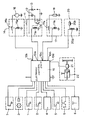
- the device comprises a position sensor 1 intended to be associated with the accelerator control pedal (not illustrated) of a motor vehicle.
- This position sensor can be constituted simply by a switch, which closes when the accelerator pedal is depressed.
- Reference numeral 2 indicates a further position sensor, intended to be associated with the vehicle brake pedal, and likewise constituted, for example, by a switch.
- Reference numeral 3 indicates a speed sensor of known type, for providing an electrical signal indicative of the speed of rotation of the engine crank shaft
- Reference numeral 4 indicates a tachometric sensor intended to provide, in operation, an electrical signal indicative of the speed of the vehicle
- Reference numeral 5 indicates a further position sensor, for example a switch, associated with the control member of a device for providing an enriched starting mixture.
- the apparatus further includes a temperature sensor 6 intended to be associated with the motor vehic.le engine in order to detect the temperature thereof. In water cooled engines this sensor can be disposed for example in such a way as to detect the temperature of the cooling water of the engine.
- Reference numeral 7 indicates a further position sensor (for example a switch) associated with the gear selection lever- (not illustrated) and intended to output an electrical enable signal when this lever is in the"drive"position.
- the sensor 1 to 7 are connected to corresponding inputs of an electronic monitoring and control unit 10, implemented with the use of microprocessors, for example the Motorola MC 68705 microprocessor.
- This unit has a first output 10a connected to the control input of a controlled switch device 11.
- this switch device is constituted by a relay having an excitation winding 11a which controls a movable contact member 11b interposed in the line connecting the on-board voltage source (battery) of the motor vehicle with the primary winding 12 of the ignition coil.
- the secondary winding of this coil is indicated 13.
- the movable contact 11b is normally closed and is arranged to move to its open position upon excitation of the winding 11a, thereby interrupting the ignition circuit of the engine.
- the monitoring and control unit 10 has a further output 10b connected to the control input of a controlled switch device 14 also constituted, for example, by a relay with a winding 14a which controls a movable contact 14b. This latter is interposed in the line which connects the electric starter motor 16 of the engine to the battery.
- the monitoring and control unit 10 has a further output 10c connected to the control input of a further controlled switch device 17. This latter also comprises, for example, a relay with an excitation winding 17a which controls a movable contact 17b interposed between the voltage supply source (battery) and a series of auxiliary electrical devices of the motor vehicle, generally indicated 18.
- auxiliary electrical devices is intended to mean all the on-board electrical equipment, the operation of which is not essential to the running of the motnr vehicle. Such devices can be constituted, for example, by defrosting or demisting resistors for the rear screen of the motor vehicle, the electric cigarette lighter etc.
- a further output 10d of the monitoring and control unit 10 is connected to an electromagnetically controlled shut-off device 20 comprising a control winding 20a and a movable core 20b.
- This core serves as a shutter and is intended to be disposed in the slow running duct (not illustrated) of the carburettor or mixer of the engine, and can assume a working position and a rest position, in which it respectively shuts off and does not shut off this duct.
- Another output 10e of the electronic unit 10 is connected to the control input of a shut-off device 21 disposed downstream of the master cylinder 22 of the brake system of the motor vehicle.
- This shut-off device can be constituted, for example, by an electrically controlled valve. When it is activated, this device de-couples the braking circuit (the downstream circuit) from the master cylinder 22 in such a way that the pressure in the braking circuit downstream of this device (or even only in the part of the braking circuit relating to one axle) is then maintained substantially equal to the value assumed at the moment at which this device is activated, until subsequent de-activation of the device.
- a manually-operable control device 9 is connected to a further input of the monitoring and control unit 10.
- This device 9 is constituted for example by a monostable switch (toggle switch), intended to be disposed in a position easily accessible to the driver, and permitting the activation and de-activation of the entire control apparatus described above.
- the stop-start device operates in the following manner.
- the monitoring and control unit 10 When the user activates the system described above, by operation of the control switch 9, the monitoring and control unit 10 is energised. This unit is arranged, using known techniques, to cause activation of the controlled switch device 11 to switch off the motor vehicle engine when the following conditions occur simultaneously:
- the unit 10 is arranged to cause the engine to be turned off if both the brake and accelerator pedals are released.
- the monitoring and control unit 10 can possibly further be arranged to cause the engine to be turned off by means of the oontrolled switch 11, after the elapse of a predetermined delay starting from the last release of the brake pedal.
- the control unit 10 is arranged to permit activation of the shut-off device 21: activation takes place as soon as the brake pedal is depressed. In this way the tendency of the vehicle, when stopped or almost stationary with the motor running and the transmission in "drive”, to advance during the interval of time (for example 0.5-3 seconds as explained above) which falls between the occurrence of the said conditions and the engine being turned off (stop) by the unit 10, is avoided.
- the activation of the shut-off device 21 causes the maintenance of a residual braking action even after the brake pedal has been released.
- the electronic monitoring and control unit 10 causes excitation of the control switch 14, the de-activation of the switch 21, and the restarting of the engine by means of the starter motor 16, when the following conditions occur:
- the monitoring and control unit 10 de-energises the relay 11 restoring the electrical continuity of the ignition circuit, and energises the relay 14 causing activation of the starter motor of the internal combustion engine, which therefore starts up again.
- the relay 17 is energised when the relay 11 is energised, and de-energised when the relay 14 is energised. In this way, when the stop-start device causes the motor to be turned off, the supply feeding the auxiliary electrical devices of the motor vehicle, some of which may have been previously activated, is interrupted.
- the relay 17 is conveniently of the delayed de-activation type in order to avoid the motor vehicle battery being overloaded by auxiliary electrical equipment which may have been previously activated.
- the monitoring and control unit 10 is arranged to permit activation of the shut-off device 20. This activation takes place when the position sensor 1 indicates that the accelerator pedal has been released. In this situation the butterfly valve of the carburettor or mixer of the engine is in the closed position and the shutter 20b completely shuts off the slow running duct. Supply of fuel to the engine therefore ceases.
- a predetermined value for example 1500 rpm
- the monitoring and control unit 10 is further arranged to de-energise the shut off device 20 as soon as the speed of rotation of the engine falls below a predetermined value (for example 1000 rpm) and, with the engine stopped, to allow it a more rapid restarting. In this condition, fuel is resupplied to the engine through the slow running duct of the carburretor: the engine can therefore be readily restarted.
- a predetermined value for example 1000 rpm
- the provision of the shut off device 20 controlled in the manner explained above makes it possible to achieve a significant fuel saving.
- the sensors 5 and 6 are intended to provide signals inhibiting the operation of the monitoring and control unit 10 respectively when the mixture enrichment device is activated and when the temperature of the motor is less than the minimum predetermined threshold.
- the activation and de-activation of the actuator devices controlled by the unit 10 can be determined by the occurrence of circumstances other than the conditions listed hereinabove.
- the turning off of the engine when halted can be made conditional upon the level of charge in ' the motor vehicle battery being greater than a minimum predetermined value sufficient to allow subsequent restarting of the engine.
Applications Claiming Priority (2)
| Application Number | Priority Date | Filing Date | Title |
|---|---|---|---|
| IT6728984 | 1984-03-26 | ||
| IT67289/84A IT1196693B (it) | 1984-03-26 | 1984-03-26 | Dispositivo stop start per il controllo del funzionamento del motore a combustione interna di un autoveicolo provvisto di cambio automatico |
Publications (2)
| Publication Number | Publication Date |
|---|---|
| EP0158605A1 true EP0158605A1 (fr) | 1985-10-16 |
| EP0158605B1 EP0158605B1 (fr) | 1988-07-20 |
Family
ID=11301179
Family Applications (1)
| Application Number | Title | Priority Date | Filing Date |
|---|---|---|---|
| EP85830049A Expired EP0158605B1 (fr) | 1984-03-26 | 1985-02-27 | Dispositif d'arrêt-démarrage pour commander l'opération d'un moteur à combustion interne d'un véhicule à transmission automatique |
Country Status (6)
| Country | Link |
|---|---|
| US (1) | US4630577A (fr) |
| EP (1) | EP0158605B1 (fr) |
| JP (1) | JPS60219425A (fr) |
| DE (1) | DE3563828D1 (fr) |
| ES (1) | ES284974Y (fr) |
| IT (1) | IT1196693B (fr) |
Cited By (14)
| Publication number | Priority date | Publication date | Assignee | Title |
|---|---|---|---|---|
| EP0377341A1 (fr) * | 1988-12-31 | 1990-07-11 | Steve Brian Goodhand | Dispositif de démarrage pour moteur à combustion interne |
| FR2647724A1 (fr) * | 1989-06-06 | 1990-12-07 | Fichtel & Sachs Ag | Dispositif de commande d'un embrayage a friction de vehicule automobile |
| EP0766002A1 (fr) * | 1995-09-28 | 1997-04-02 | Isuzu Motors Limited | Système automatique d'arrêt/redémarrage pour moteur |
| GB2306577A (en) * | 1995-10-18 | 1997-05-07 | Isaac Noel Moody | Vehicle engine stop-start control |
| WO2000024603A1 (fr) * | 1998-10-28 | 2000-05-04 | Luk Lamellen Und Kupplungsbau Gmbh | Procede de commande marche/arret d'un vehicule automobile pourvu d'un embrayage automatise |
| DE10023331A1 (de) * | 2000-05-12 | 2001-06-28 | Daimler Chrysler Ag | Verfahren zum Abstellen einer Brennkraftmaschine eines Fahrzeugs |
| EP1995451A2 (fr) | 2007-05-23 | 2008-11-26 | Peugeot Citroen Automobiles SA | Procédé de commande de l'arrêt et du redémarrage automatique du moteur d'un véhicule |
| US8326520B2 (en) | 2008-12-11 | 2012-12-04 | Bayerische Motoren Werke Aktiengesellschaft | Process for automatically turning off and starting an internal-combustion engine |
| US8323152B2 (en) | 2008-12-03 | 2012-12-04 | Bayerische Motoren Werke Aktiengesellschaft | Method for automatic shutdown of an internal combustion engine |
| US9410524B2 (en) | 2014-05-12 | 2016-08-09 | Bayerische Motoren Werke Aktiengesellschaft | Method and device for automatically shutting off an internal combustion engine |
| DE202016002493U1 (de) | 2016-04-18 | 2017-07-20 | GM Global Technology Operations LLC (n. d. Ges. d. Staates Delaware) | Zündschlossanlage eines Kraftfahrzeugs, Kraftfahrzeug sowie Computerprogrammprodukt |
| EP2666995A4 (fr) * | 2011-01-21 | 2018-04-25 | Toyota Jidosha Kabushiki Kaisha | Dispositif de commande de véhicule |
| DE102008031341B4 (de) | 2008-07-02 | 2019-03-21 | Bayerische Motoren Werke Aktiengesellschaft | Verfahren und Vorrichtung zum Beeinflussen einer Motor-Stopp-Automatik eines Kraftfahrzeugs |
| DE102008061791B4 (de) | 2008-09-30 | 2019-10-02 | Bayerische Motoren Werke Aktiengesellschaft | Verfahren zum automatischen Abschalten einer Brennkraftmaschine |
Families Citing this family (41)
| Publication number | Priority date | Publication date | Assignee | Title |
|---|---|---|---|---|
| JPH01253566A (ja) * | 1988-04-01 | 1989-10-09 | Mitsubishi Electric Corp | スタータ保護装置 |
| DE4133558A1 (de) * | 1991-10-10 | 1993-04-15 | Bosch Gmbh Robert | Steuersystem fuer die elektrische kraftstoffpumpe einer brennkraftmaschine |
| JP2868974B2 (ja) * | 1993-06-16 | 1999-03-10 | 三菱電機株式会社 | エンジンの自動始動停止装置 |
| US5695430A (en) * | 1994-09-21 | 1997-12-09 | Moyer; David F. | Hybrid internal combustion engine |
| JPH10247103A (ja) * | 1997-03-04 | 1998-09-14 | Nissan Motor Co Ltd | メモリ書き換え装置 |
| JP3815101B2 (ja) * | 1999-02-10 | 2006-08-30 | 日産自動車株式会社 | エンジンの自動停止装置 |
| DE19907851A1 (de) * | 1999-02-24 | 2000-08-31 | Bayerische Motoren Werke Ag | Verfahren zur Zylinderab- und -zuschaltung bei einer Kraftfahrzeug-Brennkraftmaschine |
| JP3649031B2 (ja) * | 1999-03-19 | 2005-05-18 | 日産自動車株式会社 | 車両のエンジン自動停止再始動装置 |
| JP3343679B2 (ja) * | 1999-07-06 | 2002-11-11 | 本田技研工業株式会社 | 車両用動力伝達装置の制御装置 |
| JP4051870B2 (ja) * | 2000-09-05 | 2008-02-27 | スズキ株式会社 | エンジンの自動停止始動制御装置 |
| GB0113125D0 (en) * | 2001-05-31 | 2001-07-18 | Meritor Light Vehicle Sys Ltd | Start system |
| JP2003041967A (ja) * | 2001-07-26 | 2003-02-13 | Toyota Motor Corp | 内燃機関の自動停止制御装置 |
| JP3941441B2 (ja) * | 2001-09-11 | 2007-07-04 | トヨタ自動車株式会社 | 内燃機関の始動時制御装置 |
| DE50110053D1 (de) | 2001-10-13 | 2006-07-20 | Ford Global Tech Inc | Verfahren zur Steuerung der Brennkraftmaschine eines Kraftfahrzeuges mit Stop/Start-Funktion |
| FR2835291B1 (fr) * | 2002-01-30 | 2005-12-02 | Defontaine Sa | Dispositif pour actionner automatiquement le demarreur du moteur thermique d'un vehicule |
| JP2004225576A (ja) * | 2003-01-21 | 2004-08-12 | Suzuki Motor Corp | エンジンの自動停止始動制御装置 |
| DE10316604A1 (de) * | 2003-04-11 | 2004-11-04 | Bayerische Motoren Werke Ag | Verfahren zum automatischen Abschalten einer Brennkraftmaschine |
| DE10317092A1 (de) * | 2003-04-14 | 2004-11-11 | Robert Bosch Gmbh | Vorrichtung zur Verbesserung des Start-Stopp-Betriebes eines Fahrzeugs |
| DE10317094A1 (de) * | 2003-04-14 | 2004-11-11 | Robert Bosch Gmbh | Vorrichtung zur Verbesserung des Start-Stopp-Betriebes eines Fahrzeugs |
| DE10317649A1 (de) * | 2003-04-17 | 2004-11-04 | Robert Bosch Gmbh | Verfahren und Vorrichtung zum Betreiben eines Verbrennungsmotors im Schiebebetrieb |
| DE102005034602B4 (de) * | 2005-07-25 | 2015-07-16 | Robert Bosch Gmbh | Verfahren zum Betreiben eines Kraftfahrzeugs mit einer Brennkraftmaschine, Computerprogramm-Produkt, elektrisches Speichermedium für eine Steuer- und/oder Regeleinrichtung sowie Steuer- und/oder Regeleinrichtung für ein Kraftfahrzeug |
| DE102006010905B4 (de) * | 2006-03-09 | 2012-12-13 | Robert Bosch Gmbh | Verfahren zur Steuerung eines Stellglieds eines Kraftfahrzeugs |
| DE102008027659A1 (de) | 2008-06-10 | 2009-12-17 | Bayerische Motoren Werke Aktiengesellschaft | Einrichtung und Verfahren zum Abstellen und Starten einer Kraftfahrzeug-Brennkraftmaschine |
| DE102008031340A1 (de) | 2008-07-02 | 2010-01-07 | Bayerische Motoren Werke Aktiengesellschaft | Verfahren zum Beeinflussen einer Motor-Stopp-Automatik eines Kraftfahrzeugs |
| CN101585316B (zh) * | 2008-11-03 | 2014-01-08 | 贾振雷 | 车辆驾驶节能控制方法及节能器 |
| DE102008060348A1 (de) | 2008-12-03 | 2010-06-10 | Bayerische Motoren Werke Aktiengesellschaft | Verfahren zum automatischen Abschalten und Starten einer Brennkraftmaschine |
| JP5215204B2 (ja) * | 2009-01-29 | 2013-06-19 | 株式会社クボタ | 作業機の表示構造 |
| GB0902885D0 (en) * | 2009-02-20 | 2009-04-08 | Bouchard Michel | Fuel management system for a motor vehicle |
| DE102009039090A1 (de) | 2009-08-27 | 2011-03-03 | Bayerische Motoren Werke Aktiengesellschaft | Verfahren zum automatischen Abschalten und Einschalten einer Brennkraftmaschine |
| KR101144430B1 (ko) * | 2009-12-04 | 2012-05-10 | 현대자동차주식회사 | 아이들 스탑 앤 고 적용 차량의 제동장치 및 그 제어방법 |
| JP2011208698A (ja) * | 2010-03-29 | 2011-10-20 | Aisin Aw Co Ltd | 動力伝達機構の制御装置および動力伝達装置 |
| DE102010041104B4 (de) | 2010-09-21 | 2020-07-30 | Bayerische Motoren Werke Aktiengesellschaft | Verfahren zum automatischen Abschalten einer Brennkraftmaschine |
| US10137908B2 (en) * | 2011-06-13 | 2018-11-27 | General Electric Company | Vehicle traction control system and method |
| DE102012212038A1 (de) | 2012-07-10 | 2014-01-30 | Bayerische Motoren Werke Aktiengesellschaft | Verfahren zum automatischen Abschalten einer Brennkraftmaschine |
| DE102012212035B4 (de) | 2012-07-10 | 2021-03-18 | Bayerische Motoren Werke Aktiengesellschaft | Verfahren zur Steuerung eines Automatikgetriebes in Kraftfahrzeugen |
| DE102012218737B4 (de) | 2012-10-15 | 2022-03-31 | Bayerische Motoren Werke Aktiengesellschaft | Verfahren zum automatischen Abschalten und Starten einer Brennkraftmaschine |
| JP6171917B2 (ja) * | 2013-12-18 | 2017-08-02 | 株式会社デンソー | エンジン始動装置 |
| BR102015031641B1 (pt) * | 2015-12-17 | 2022-09-20 | Bosch Soluções Integradas Brasil Ltda | Processo de controle de um dispositivo de desligamento e partida para o motor à combustão de um veículo pesado, e tal dispositivo |
| BR102015031645B1 (pt) * | 2015-12-17 | 2022-09-27 | Bosch Soluções Integradas Brasil Ltda. | Processo de controle de um dispositivo de desligamento e partida para o motor a combustão de um veículo pesado, e tal dispositivo |
| DE102016200968A1 (de) | 2016-01-25 | 2017-07-27 | Bayerische Motoren Werke Aktiengesellschaft | Start-Stopp-Einrichtung zum Einleiten eines automatischen Anschaltvorgangs einer Antriebsmaschine in einem Kraftfahrzeug |
| US10160409B2 (en) * | 2017-01-12 | 2018-12-25 | Fca Us Llc | Engine stop-start auxiliary battery disconnect detection |
Citations (6)
| Publication number | Priority date | Publication date | Assignee | Title |
|---|---|---|---|---|
| DE2803145A1 (de) * | 1978-01-25 | 1979-07-26 | Bosch Gmbh Robert | Verfahren und einrichtung zum automatischen abstellen und erneuten starten eines motors zur kraftstoffeinsparung |
| DE3043309A1 (de) * | 1980-11-17 | 1982-07-15 | Formiwa Forschungs-GmbH, 7800 Freiburg | Vorrichtung zum abstellen des motors eines kraftfahrzeuges mit automatik-getriebe |
| US4362133A (en) * | 1981-05-08 | 1982-12-07 | General Motors Corporation | Automatic engine shutdown and restart system |
| FR2523530A1 (fr) * | 1982-03-18 | 1983-09-23 | Rau Swf Autozubehoer | Dispositif d'arret-demarrage pour moteur de vehicule automobile |
| GB2117070A (en) * | 1982-03-22 | 1983-10-05 | Rau Swf Autozubehoer | Motor vehicle control arrangement |
| DE3220112A1 (de) * | 1982-05-28 | 1983-12-01 | Robert Bosch Gmbh, 7000 Stuttgart | Vorrichtung zum anlassen und abstellen einer brennkraftmaschine |
Family Cites Families (8)
| Publication number | Priority date | Publication date | Assignee | Title |
|---|---|---|---|---|
| US3498426A (en) * | 1966-10-21 | 1970-03-03 | Akio Nakano | Hydraulic brake operating system for a motor vehicle |
| US3842950A (en) * | 1971-04-19 | 1974-10-22 | Fail Safe Brake Corp | Automatic parking or emergency brake system for motor vehicles |
| US3763975A (en) * | 1972-06-12 | 1973-10-09 | J Fontaine | Brake with vehicle speed & accelerator controls |
| US4286683A (en) * | 1979-08-20 | 1981-09-01 | Zemco, Inc. | Stop/start control system for engine |
| US4364343A (en) * | 1981-05-08 | 1982-12-21 | General Motors Corporation | Automatic engine shutdown and restart system |
| JPS5835245A (ja) * | 1981-08-25 | 1983-03-01 | Toyota Motor Corp | エンジン自動停止始動装置 |
| JPS5939946A (ja) * | 1982-08-27 | 1984-03-05 | Honda Motor Co Ltd | 車両の長期アイドル運転防止装置 |
| DE3343018C2 (de) * | 1982-12-02 | 1986-02-20 | Mitsubishi Denki K.K., Tokio/Tokyo | Vorrichtung zum automatischen starten und stoppen einer verbrennungskraftmaschine |
-
1984
- 1984-03-26 IT IT67289/84A patent/IT1196693B/it active
-
1985
- 1985-02-27 EP EP85830049A patent/EP0158605B1/fr not_active Expired
- 1985-02-27 DE DE8585830049T patent/DE3563828D1/de not_active Expired
- 1985-02-28 ES ES1985284974U patent/ES284974Y/es not_active Expired
- 1985-03-26 JP JP60059684A patent/JPS60219425A/ja active Pending
- 1985-03-26 US US06/716,055 patent/US4630577A/en not_active Expired - Fee Related
Patent Citations (6)
| Publication number | Priority date | Publication date | Assignee | Title |
|---|---|---|---|---|
| DE2803145A1 (de) * | 1978-01-25 | 1979-07-26 | Bosch Gmbh Robert | Verfahren und einrichtung zum automatischen abstellen und erneuten starten eines motors zur kraftstoffeinsparung |
| DE3043309A1 (de) * | 1980-11-17 | 1982-07-15 | Formiwa Forschungs-GmbH, 7800 Freiburg | Vorrichtung zum abstellen des motors eines kraftfahrzeuges mit automatik-getriebe |
| US4362133A (en) * | 1981-05-08 | 1982-12-07 | General Motors Corporation | Automatic engine shutdown and restart system |
| FR2523530A1 (fr) * | 1982-03-18 | 1983-09-23 | Rau Swf Autozubehoer | Dispositif d'arret-demarrage pour moteur de vehicule automobile |
| GB2117070A (en) * | 1982-03-22 | 1983-10-05 | Rau Swf Autozubehoer | Motor vehicle control arrangement |
| DE3220112A1 (de) * | 1982-05-28 | 1983-12-01 | Robert Bosch Gmbh, 7000 Stuttgart | Vorrichtung zum anlassen und abstellen einer brennkraftmaschine |
Cited By (16)
| Publication number | Priority date | Publication date | Assignee | Title |
|---|---|---|---|---|
| EP0377341A1 (fr) * | 1988-12-31 | 1990-07-11 | Steve Brian Goodhand | Dispositif de démarrage pour moteur à combustion interne |
| FR2647724A1 (fr) * | 1989-06-06 | 1990-12-07 | Fichtel & Sachs Ag | Dispositif de commande d'un embrayage a friction de vehicule automobile |
| EP0766002A1 (fr) * | 1995-09-28 | 1997-04-02 | Isuzu Motors Limited | Système automatique d'arrêt/redémarrage pour moteur |
| GB2306577A (en) * | 1995-10-18 | 1997-05-07 | Isaac Noel Moody | Vehicle engine stop-start control |
| GB2306577B (en) * | 1995-10-18 | 1999-05-05 | Isaac Noel Moody | Engine controller for motor vehicles |
| WO2000024603A1 (fr) * | 1998-10-28 | 2000-05-04 | Luk Lamellen Und Kupplungsbau Gmbh | Procede de commande marche/arret d'un vehicule automobile pourvu d'un embrayage automatise |
| FR2785237A1 (fr) * | 1998-10-28 | 2000-05-05 | Luk Getriebe Systeme Gmbh | Procede de commande d'un accouplement |
| DE10023331A1 (de) * | 2000-05-12 | 2001-06-28 | Daimler Chrysler Ag | Verfahren zum Abstellen einer Brennkraftmaschine eines Fahrzeugs |
| EP1995451A2 (fr) | 2007-05-23 | 2008-11-26 | Peugeot Citroen Automobiles SA | Procédé de commande de l'arrêt et du redémarrage automatique du moteur d'un véhicule |
| DE102008031341B4 (de) | 2008-07-02 | 2019-03-21 | Bayerische Motoren Werke Aktiengesellschaft | Verfahren und Vorrichtung zum Beeinflussen einer Motor-Stopp-Automatik eines Kraftfahrzeugs |
| DE102008061791B4 (de) | 2008-09-30 | 2019-10-02 | Bayerische Motoren Werke Aktiengesellschaft | Verfahren zum automatischen Abschalten einer Brennkraftmaschine |
| US8323152B2 (en) | 2008-12-03 | 2012-12-04 | Bayerische Motoren Werke Aktiengesellschaft | Method for automatic shutdown of an internal combustion engine |
| US8326520B2 (en) | 2008-12-11 | 2012-12-04 | Bayerische Motoren Werke Aktiengesellschaft | Process for automatically turning off and starting an internal-combustion engine |
| EP2666995A4 (fr) * | 2011-01-21 | 2018-04-25 | Toyota Jidosha Kabushiki Kaisha | Dispositif de commande de véhicule |
| US9410524B2 (en) | 2014-05-12 | 2016-08-09 | Bayerische Motoren Werke Aktiengesellschaft | Method and device for automatically shutting off an internal combustion engine |
| DE202016002493U1 (de) | 2016-04-18 | 2017-07-20 | GM Global Technology Operations LLC (n. d. Ges. d. Staates Delaware) | Zündschlossanlage eines Kraftfahrzeugs, Kraftfahrzeug sowie Computerprogrammprodukt |
Also Published As
| Publication number | Publication date |
|---|---|
| ES284974Y (es) | 1986-04-16 |
| DE3563828D1 (en) | 1988-08-25 |
| US4630577A (en) | 1986-12-23 |
| JPS60219425A (ja) | 1985-11-02 |
| IT1196693B (it) | 1988-11-25 |
| IT8467289A0 (it) | 1984-03-26 |
| ES284974U (es) | 1985-08-01 |
| IT8467289A1 (it) | 1985-09-26 |
| EP0158605B1 (fr) | 1988-07-20 |
Similar Documents
| Publication | Publication Date | Title |
|---|---|---|
| US4630577A (en) | Stop-start device for controlling the operation of an internal combustion engine of a vehicle provided with an automatic transmission | |
| US4494497A (en) | Automatic engine stop-restart system | |
| US4510396A (en) | Method of controlling automatic stop and restart of an engine | |
| JP4211208B2 (ja) | 燃料消費節約型自動車 | |
| US4485772A (en) | Automatic engine stop-restart system | |
| US4768610A (en) | Device on a motor vehicle | |
| US4416230A (en) | Engine control apparatus | |
| GB1601156A (en) | Method and apparatus for controlling the engine of a motor vehicle | |
| JP3613970B2 (ja) | 車両用エンジンの再始動制御装置及び自動停止・再始動制御装置 | |
| US4479063A (en) | Automatic engine stop-restart system | |
| JPS59126069A (ja) | 始動装置 | |
| US9599088B2 (en) | System for cranking internal combustion engine by engagement of pinion with ring gear | |
| US4497291A (en) | Full economizer for vehicles | |
| US4610146A (en) | Operating control device for air conditioner for use in vehicle | |
| US3779349A (en) | Vehicular air-pollution preventive apparatus | |
| JPS5823250A (ja) | エンジン自動停止始動の制御方法 | |
| JPS5823252A (ja) | エンジン自動停止始動装置 | |
| WO1998014702A1 (fr) | Systeme d'arret automatique et de redemarrage automatique d'un moteur automobile | |
| FR2549141A1 (fr) | Dispositif arret-demarrage pour la commande du fonctionnement d'un moteur a combustion interne de vehicule automobile | |
| JPH07277027A (ja) | 車両の駆動ユニットにおける調整操作部材の制御方法及び装置 | |
| JP3748407B2 (ja) | アイドルストップ装置 | |
| TW201410967A (zh) | 操作機車的方法 | |
| JPH0244039Y2 (fr) | ||
| JPH10131781A (ja) | エンジン制御装置 | |
| JPH0315018B2 (fr) |
Legal Events
| Date | Code | Title | Description |
|---|---|---|---|
| PUAI | Public reference made under article 153(3) epc to a published international application that has entered the european phase |
Free format text: ORIGINAL CODE: 0009012 |
|
| AK | Designated contracting states |
Designated state(s): BE DE FR GB NL |
|
| 17P | Request for examination filed |
Effective date: 19850925 |
|
| 17Q | First examination report despatched |
Effective date: 19861104 |
|
| D17Q | First examination report despatched (deleted) | ||
| GRAA | (expected) grant |
Free format text: ORIGINAL CODE: 0009210 |
|
| AK | Designated contracting states |
Kind code of ref document: B1 Designated state(s): BE DE FR GB NL |
|
| REF | Corresponds to: |
Ref document number: 3563828 Country of ref document: DE Date of ref document: 19880825 |
|
| ET | Fr: translation filed | ||
| PLBE | No opposition filed within time limit |
Free format text: ORIGINAL CODE: 0009261 |
|
| STAA | Information on the status of an ep patent application or granted ep patent |
Free format text: STATUS: NO OPPOSITION FILED WITHIN TIME LIMIT |
|
| 26N | No opposition filed | ||
| PGFP | Annual fee paid to national office [announced via postgrant information from national office to epo] |
Ref country code: GB Payment date: 19940118 Year of fee payment: 10 |
|
| PGFP | Annual fee paid to national office [announced via postgrant information from national office to epo] |
Ref country code: DE Payment date: 19940119 Year of fee payment: 10 |
|
| PGFP | Annual fee paid to national office [announced via postgrant information from national office to epo] |
Ref country code: BE Payment date: 19940127 Year of fee payment: 10 |
|
| PGFP | Annual fee paid to national office [announced via postgrant information from national office to epo] |
Ref country code: FR Payment date: 19940228 Year of fee payment: 10 Ref country code: NL Payment date: 19940228 Year of fee payment: 10 |
|
| PG25 | Lapsed in a contracting state [announced via postgrant information from national office to epo] |
Ref country code: GB Effective date: 19950227 |
|
| PG25 | Lapsed in a contracting state [announced via postgrant information from national office to epo] |
Ref country code: BE Effective date: 19950228 |
|
| BERE | Be: lapsed |
Owner name: FIAT AUTO S.P.A. Effective date: 19950228 |
|
| PG25 | Lapsed in a contracting state [announced via postgrant information from national office to epo] |
Ref country code: NL Effective date: 19950901 |
|
| GBPC | Gb: european patent ceased through non-payment of renewal fee |
Effective date: 19950227 |
|
| PG25 | Lapsed in a contracting state [announced via postgrant information from national office to epo] |
Ref country code: FR Effective date: 19951031 |
|
| NLV4 | Nl: lapsed or anulled due to non-payment of the annual fee |
Effective date: 19950901 |
|
| PG25 | Lapsed in a contracting state [announced via postgrant information from national office to epo] |
Ref country code: DE Effective date: 19951101 |
|
| REG | Reference to a national code |
Ref country code: FR Ref legal event code: ST |