EP0158605A1 - A stop-start device for controlling the operation of an internal combustion engine of a vehicle provided with an automatic transmission - Google Patents
A stop-start device for controlling the operation of an internal combustion engine of a vehicle provided with an automatic transmission Download PDFInfo
- Publication number
- EP0158605A1 EP0158605A1 EP85830049A EP85830049A EP0158605A1 EP 0158605 A1 EP0158605 A1 EP 0158605A1 EP 85830049 A EP85830049 A EP 85830049A EP 85830049 A EP85830049 A EP 85830049A EP 0158605 A1 EP0158605 A1 EP 0158605A1
- Authority
- EP
- European Patent Office
- Prior art keywords
- engine
- speed
- activate
- control unit
- less
- Prior art date
- Legal status (The legal status is an assumption and is not a legal conclusion. Google has not performed a legal analysis and makes no representation as to the accuracy of the status listed.)
- Granted
Links
Images
Classifications
-
- F—MECHANICAL ENGINEERING; LIGHTING; HEATING; WEAPONS; BLASTING
- F02—COMBUSTION ENGINES; HOT-GAS OR COMBUSTION-PRODUCT ENGINE PLANTS
- F02N—STARTING OF COMBUSTION ENGINES; STARTING AIDS FOR SUCH ENGINES, NOT OTHERWISE PROVIDED FOR
- F02N11/00—Starting of engines by means of electric motors
- F02N11/08—Circuits or control means specially adapted for starting of engines
- F02N11/0814—Circuits or control means specially adapted for starting of engines comprising means for controlling automatic idle-start-stop
- F02N11/0818—Conditions for starting or stopping the engine or for deactivating the idle-start-stop mode
-
- B—PERFORMING OPERATIONS; TRANSPORTING
- B60—VEHICLES IN GENERAL
- B60W—CONJOINT CONTROL OF VEHICLE SUB-UNITS OF DIFFERENT TYPE OR DIFFERENT FUNCTION; CONTROL SYSTEMS SPECIALLY ADAPTED FOR HYBRID VEHICLES; ROAD VEHICLE DRIVE CONTROL SYSTEMS FOR PURPOSES NOT RELATED TO THE CONTROL OF A PARTICULAR SUB-UNIT
- B60W10/00—Conjoint control of vehicle sub-units of different type or different function
- B60W10/04—Conjoint control of vehicle sub-units of different type or different function including control of propulsion units
-
- B—PERFORMING OPERATIONS; TRANSPORTING
- B60—VEHICLES IN GENERAL
- B60W—CONJOINT CONTROL OF VEHICLE SUB-UNITS OF DIFFERENT TYPE OR DIFFERENT FUNCTION; CONTROL SYSTEMS SPECIALLY ADAPTED FOR HYBRID VEHICLES; ROAD VEHICLE DRIVE CONTROL SYSTEMS FOR PURPOSES NOT RELATED TO THE CONTROL OF A PARTICULAR SUB-UNIT
- B60W10/00—Conjoint control of vehicle sub-units of different type or different function
- B60W10/18—Conjoint control of vehicle sub-units of different type or different function including control of braking systems
-
- B—PERFORMING OPERATIONS; TRANSPORTING
- B60—VEHICLES IN GENERAL
- B60W—CONJOINT CONTROL OF VEHICLE SUB-UNITS OF DIFFERENT TYPE OR DIFFERENT FUNCTION; CONTROL SYSTEMS SPECIALLY ADAPTED FOR HYBRID VEHICLES; ROAD VEHICLE DRIVE CONTROL SYSTEMS FOR PURPOSES NOT RELATED TO THE CONTROL OF A PARTICULAR SUB-UNIT
- B60W30/00—Purposes of road vehicle drive control systems not related to the control of a particular sub-unit, e.g. of systems using conjoint control of vehicle sub-units, or advanced driver assistance systems for ensuring comfort, stability and safety or drive control systems for propelling or retarding the vehicle
- B60W30/18—Propelling the vehicle
- B60W30/18009—Propelling the vehicle related to particular drive situations
- B60W30/18018—Start-stop drive, e.g. in a traffic jam
-
- B—PERFORMING OPERATIONS; TRANSPORTING
- B60—VEHICLES IN GENERAL
- B60W—CONJOINT CONTROL OF VEHICLE SUB-UNITS OF DIFFERENT TYPE OR DIFFERENT FUNCTION; CONTROL SYSTEMS SPECIALLY ADAPTED FOR HYBRID VEHICLES; ROAD VEHICLE DRIVE CONTROL SYSTEMS FOR PURPOSES NOT RELATED TO THE CONTROL OF A PARTICULAR SUB-UNIT
- B60W30/00—Purposes of road vehicle drive control systems not related to the control of a particular sub-unit, e.g. of systems using conjoint control of vehicle sub-units, or advanced driver assistance systems for ensuring comfort, stability and safety or drive control systems for propelling or retarding the vehicle
- B60W30/18—Propelling the vehicle
- B60W30/1819—Propulsion control with control means using analogue circuits, relays or mechanical links
-
- B—PERFORMING OPERATIONS; TRANSPORTING
- B60—VEHICLES IN GENERAL
- B60W—CONJOINT CONTROL OF VEHICLE SUB-UNITS OF DIFFERENT TYPE OR DIFFERENT FUNCTION; CONTROL SYSTEMS SPECIALLY ADAPTED FOR HYBRID VEHICLES; ROAD VEHICLE DRIVE CONTROL SYSTEMS FOR PURPOSES NOT RELATED TO THE CONTROL OF A PARTICULAR SUB-UNIT
- B60W2510/00—Input parameters relating to a particular sub-units
- B60W2510/06—Combustion engines, Gas turbines
- B60W2510/0638—Engine speed
-
- B—PERFORMING OPERATIONS; TRANSPORTING
- B60—VEHICLES IN GENERAL
- B60W—CONJOINT CONTROL OF VEHICLE SUB-UNITS OF DIFFERENT TYPE OR DIFFERENT FUNCTION; CONTROL SYSTEMS SPECIALLY ADAPTED FOR HYBRID VEHICLES; ROAD VEHICLE DRIVE CONTROL SYSTEMS FOR PURPOSES NOT RELATED TO THE CONTROL OF A PARTICULAR SUB-UNIT
- B60W2520/00—Input parameters relating to overall vehicle dynamics
- B60W2520/10—Longitudinal speed
-
- B—PERFORMING OPERATIONS; TRANSPORTING
- B60—VEHICLES IN GENERAL
- B60W—CONJOINT CONTROL OF VEHICLE SUB-UNITS OF DIFFERENT TYPE OR DIFFERENT FUNCTION; CONTROL SYSTEMS SPECIALLY ADAPTED FOR HYBRID VEHICLES; ROAD VEHICLE DRIVE CONTROL SYSTEMS FOR PURPOSES NOT RELATED TO THE CONTROL OF A PARTICULAR SUB-UNIT
- B60W2540/00—Input parameters relating to occupants
- B60W2540/10—Accelerator pedal position
-
- B—PERFORMING OPERATIONS; TRANSPORTING
- B60—VEHICLES IN GENERAL
- B60W—CONJOINT CONTROL OF VEHICLE SUB-UNITS OF DIFFERENT TYPE OR DIFFERENT FUNCTION; CONTROL SYSTEMS SPECIALLY ADAPTED FOR HYBRID VEHICLES; ROAD VEHICLE DRIVE CONTROL SYSTEMS FOR PURPOSES NOT RELATED TO THE CONTROL OF A PARTICULAR SUB-UNIT
- B60W2540/00—Input parameters relating to occupants
- B60W2540/12—Brake pedal position
-
- B—PERFORMING OPERATIONS; TRANSPORTING
- B60—VEHICLES IN GENERAL
- B60W—CONJOINT CONTROL OF VEHICLE SUB-UNITS OF DIFFERENT TYPE OR DIFFERENT FUNCTION; CONTROL SYSTEMS SPECIALLY ADAPTED FOR HYBRID VEHICLES; ROAD VEHICLE DRIVE CONTROL SYSTEMS FOR PURPOSES NOT RELATED TO THE CONTROL OF A PARTICULAR SUB-UNIT
- B60W2540/00—Input parameters relating to occupants
- B60W2540/16—Ratio selector position
-
- F—MECHANICAL ENGINEERING; LIGHTING; HEATING; WEAPONS; BLASTING
- F02—COMBUSTION ENGINES; HOT-GAS OR COMBUSTION-PRODUCT ENGINE PLANTS
- F02N—STARTING OF COMBUSTION ENGINES; STARTING AIDS FOR SUCH ENGINES, NOT OTHERWISE PROVIDED FOR
- F02N2200/00—Parameters used for control of starting apparatus
- F02N2200/02—Parameters used for control of starting apparatus said parameters being related to the engine
- F02N2200/022—Engine speed
-
- F—MECHANICAL ENGINEERING; LIGHTING; HEATING; WEAPONS; BLASTING
- F02—COMBUSTION ENGINES; HOT-GAS OR COMBUSTION-PRODUCT ENGINE PLANTS
- F02N—STARTING OF COMBUSTION ENGINES; STARTING AIDS FOR SUCH ENGINES, NOT OTHERWISE PROVIDED FOR
- F02N2200/00—Parameters used for control of starting apparatus
- F02N2200/08—Parameters used for control of starting apparatus said parameters being related to the vehicle or its components
- F02N2200/0801—Vehicle speed
-
- F—MECHANICAL ENGINEERING; LIGHTING; HEATING; WEAPONS; BLASTING
- F02—COMBUSTION ENGINES; HOT-GAS OR COMBUSTION-PRODUCT ENGINE PLANTS
- F02N—STARTING OF COMBUSTION ENGINES; STARTING AIDS FOR SUCH ENGINES, NOT OTHERWISE PROVIDED FOR
- F02N2200/00—Parameters used for control of starting apparatus
- F02N2200/10—Parameters used for control of starting apparatus said parameters being related to driver demands or status
- F02N2200/101—Accelerator pedal position
-
- Y—GENERAL TAGGING OF NEW TECHNOLOGICAL DEVELOPMENTS; GENERAL TAGGING OF CROSS-SECTIONAL TECHNOLOGIES SPANNING OVER SEVERAL SECTIONS OF THE IPC; TECHNICAL SUBJECTS COVERED BY FORMER USPC CROSS-REFERENCE ART COLLECTIONS [XRACs] AND DIGESTS
- Y02—TECHNOLOGIES OR APPLICATIONS FOR MITIGATION OR ADAPTATION AGAINST CLIMATE CHANGE
- Y02T—CLIMATE CHANGE MITIGATION TECHNOLOGIES RELATED TO TRANSPORTATION
- Y02T10/00—Road transport of goods or passengers
- Y02T10/10—Internal combustion engine [ICE] based vehicles
- Y02T10/40—Engine management systems
Definitions
- the present invention relates to a stop-start device for controlling the operation of the internal combustion engine of a motor vehicle.
- the object of the invention is to provide such a device suitable for use in a motor vehicle provided with an automatic transmission.
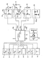
- the device comprises a position sensor 1 intended to be associated with the accelerator control pedal (not illustrated) of a motor vehicle.
- This position sensor can be constituted simply by a switch, which closes when the accelerator pedal is depressed.
- Reference numeral 2 indicates a further position sensor, intended to be associated with the vehicle brake pedal, and likewise constituted, for example, by a switch.
- Reference numeral 3 indicates a speed sensor of known type, for providing an electrical signal indicative of the speed of rotation of the engine crank shaft
- Reference numeral 4 indicates a tachometric sensor intended to provide, in operation, an electrical signal indicative of the speed of the vehicle
- Reference numeral 5 indicates a further position sensor, for example a switch, associated with the control member of a device for providing an enriched starting mixture.
- the apparatus further includes a temperature sensor 6 intended to be associated with the motor vehic.le engine in order to detect the temperature thereof. In water cooled engines this sensor can be disposed for example in such a way as to detect the temperature of the cooling water of the engine.
- Reference numeral 7 indicates a further position sensor (for example a switch) associated with the gear selection lever- (not illustrated) and intended to output an electrical enable signal when this lever is in the"drive"position.
- the sensor 1 to 7 are connected to corresponding inputs of an electronic monitoring and control unit 10, implemented with the use of microprocessors, for example the Motorola MC 68705 microprocessor.
- This unit has a first output 10a connected to the control input of a controlled switch device 11.
- this switch device is constituted by a relay having an excitation winding 11a which controls a movable contact member 11b interposed in the line connecting the on-board voltage source (battery) of the motor vehicle with the primary winding 12 of the ignition coil.
- the secondary winding of this coil is indicated 13.
- the movable contact 11b is normally closed and is arranged to move to its open position upon excitation of the winding 11a, thereby interrupting the ignition circuit of the engine.
- the monitoring and control unit 10 has a further output 10b connected to the control input of a controlled switch device 14 also constituted, for example, by a relay with a winding 14a which controls a movable contact 14b. This latter is interposed in the line which connects the electric starter motor 16 of the engine to the battery.
- the monitoring and control unit 10 has a further output 10c connected to the control input of a further controlled switch device 17. This latter also comprises, for example, a relay with an excitation winding 17a which controls a movable contact 17b interposed between the voltage supply source (battery) and a series of auxiliary electrical devices of the motor vehicle, generally indicated 18.
- auxiliary electrical devices is intended to mean all the on-board electrical equipment, the operation of which is not essential to the running of the motnr vehicle. Such devices can be constituted, for example, by defrosting or demisting resistors for the rear screen of the motor vehicle, the electric cigarette lighter etc.
- a further output 10d of the monitoring and control unit 10 is connected to an electromagnetically controlled shut-off device 20 comprising a control winding 20a and a movable core 20b.
- This core serves as a shutter and is intended to be disposed in the slow running duct (not illustrated) of the carburettor or mixer of the engine, and can assume a working position and a rest position, in which it respectively shuts off and does not shut off this duct.
- Another output 10e of the electronic unit 10 is connected to the control input of a shut-off device 21 disposed downstream of the master cylinder 22 of the brake system of the motor vehicle.
- This shut-off device can be constituted, for example, by an electrically controlled valve. When it is activated, this device de-couples the braking circuit (the downstream circuit) from the master cylinder 22 in such a way that the pressure in the braking circuit downstream of this device (or even only in the part of the braking circuit relating to one axle) is then maintained substantially equal to the value assumed at the moment at which this device is activated, until subsequent de-activation of the device.
- a manually-operable control device 9 is connected to a further input of the monitoring and control unit 10.
- This device 9 is constituted for example by a monostable switch (toggle switch), intended to be disposed in a position easily accessible to the driver, and permitting the activation and de-activation of the entire control apparatus described above.
- the stop-start device operates in the following manner.
- the monitoring and control unit 10 When the user activates the system described above, by operation of the control switch 9, the monitoring and control unit 10 is energised. This unit is arranged, using known techniques, to cause activation of the controlled switch device 11 to switch off the motor vehicle engine when the following conditions occur simultaneously:
- the unit 10 is arranged to cause the engine to be turned off if both the brake and accelerator pedals are released.
- the monitoring and control unit 10 can possibly further be arranged to cause the engine to be turned off by means of the oontrolled switch 11, after the elapse of a predetermined delay starting from the last release of the brake pedal.
- the control unit 10 is arranged to permit activation of the shut-off device 21: activation takes place as soon as the brake pedal is depressed. In this way the tendency of the vehicle, when stopped or almost stationary with the motor running and the transmission in "drive”, to advance during the interval of time (for example 0.5-3 seconds as explained above) which falls between the occurrence of the said conditions and the engine being turned off (stop) by the unit 10, is avoided.
- the activation of the shut-off device 21 causes the maintenance of a residual braking action even after the brake pedal has been released.
- the electronic monitoring and control unit 10 causes excitation of the control switch 14, the de-activation of the switch 21, and the restarting of the engine by means of the starter motor 16, when the following conditions occur:
- the monitoring and control unit 10 de-energises the relay 11 restoring the electrical continuity of the ignition circuit, and energises the relay 14 causing activation of the starter motor of the internal combustion engine, which therefore starts up again.
- the relay 17 is energised when the relay 11 is energised, and de-energised when the relay 14 is energised. In this way, when the stop-start device causes the motor to be turned off, the supply feeding the auxiliary electrical devices of the motor vehicle, some of which may have been previously activated, is interrupted.
- the relay 17 is conveniently of the delayed de-activation type in order to avoid the motor vehicle battery being overloaded by auxiliary electrical equipment which may have been previously activated.
- the monitoring and control unit 10 is arranged to permit activation of the shut-off device 20. This activation takes place when the position sensor 1 indicates that the accelerator pedal has been released. In this situation the butterfly valve of the carburettor or mixer of the engine is in the closed position and the shutter 20b completely shuts off the slow running duct. Supply of fuel to the engine therefore ceases.
- a predetermined value for example 1500 rpm
- the monitoring and control unit 10 is further arranged to de-energise the shut off device 20 as soon as the speed of rotation of the engine falls below a predetermined value (for example 1000 rpm) and, with the engine stopped, to allow it a more rapid restarting. In this condition, fuel is resupplied to the engine through the slow running duct of the carburretor: the engine can therefore be readily restarted.
- a predetermined value for example 1000 rpm
- the provision of the shut off device 20 controlled in the manner explained above makes it possible to achieve a significant fuel saving.
- the sensors 5 and 6 are intended to provide signals inhibiting the operation of the monitoring and control unit 10 respectively when the mixture enrichment device is activated and when the temperature of the motor is less than the minimum predetermined threshold.
- the activation and de-activation of the actuator devices controlled by the unit 10 can be determined by the occurrence of circumstances other than the conditions listed hereinabove.
- the turning off of the engine when halted can be made conditional upon the level of charge in ' the motor vehicle battery being greater than a minimum predetermined value sufficient to allow subsequent restarting of the engine.
Abstract
Description
- The present invention relates to a stop-start device for controlling the operation of the internal combustion engine of a motor vehicle.
- The object of the invention is to provide such a device suitable for use in a motor vehicle provided with an automatic transmission.
- This object is achieved, according to the invention, by a device characterised in that it comprises, in combination:
- sensor means operable to provide electrical signals indicative of the speed of the vehicle, the speed of rotation of the engine, and the position of the accelerator pedal,
- actuator means arranged respectively when activated and de-activated to cause the engine to be turned off and to allow it to be re-started, and
- an electronic monitoring and control unit connected to the said sensor means, to the said actuator means and to the electric starter motor of the engine; the said unit being arranged
- to activate the actuator means whenever the signals provided by the said sensor means indicate that, for a period of time of predetermined duration the speed of rotation of the engine is less than a first predetermined value, the speed of the vehicle is less than a predetermined threshold value, and the accelerator pedal is released; and
- to de-activate the said actuator means and to activate automatically the electric starter motor when the signals provided by the said sensor means indicate that the speed of rotation of the engine is lower than a second predetermined value, less than the said first value, and the accelerator pedal is depressed.
- Further characteristics and advantages of the stop-start device according to the invention will become apparent from the following detailed description, made with reference to the attached drawings, provided purely by way of non limiting example, in which there is shown an electric diagram, partially in block form, of an embodiment of the device forming the subject of the invention.
- With reference to the drawing, the device according to the invention comprises a position sensor 1 intended to be associated with the accelerator control pedal (not illustrated) of a motor vehicle. This position sensor can be constituted simply by a switch, which closes when the accelerator pedal is depressed.
-
Reference numeral 2 indicates a further position sensor, intended to be associated with the vehicle brake pedal, and likewise constituted, for example, by a switch. -
Reference numeral 3 indicates a speed sensor of known type, for providing an electrical signal indicative of the speed of rotation of the engine crank shaft, Reference numeral 4 indicates a tachometric sensor intended to provide, in operation, an electrical signal indicative of the speed of the vehicle. Reference numeral 5 indicates a further position sensor, for example a switch, associated with the control member of a device for providing an enriched starting mixture. - The apparatus further includes a
temperature sensor 6 intended to be associated with the motor vehic.le engine in order to detect the temperature thereof. In water cooled engines this sensor can be disposed for example in such a way as to detect the temperature of the cooling water of the engine.Reference numeral 7 indicates a further position sensor (for example a switch) associated with the gear selection lever- (not illustrated) and intended to output an electrical enable signal when this lever is in the"drive"position. - The sensor 1 to 7 are connected to corresponding inputs of an electronic monitoring and
control unit 10, implemented with the use of microprocessors, for example the Motorola MC 68705 microprocessor. - This unit has a
first output 10a connected to the control input of a controlledswitch device 11. In the embodiment illustrated in the drawings this switch device is constituted by a relay having an excitation winding 11a which controls amovable contact member 11b interposed in the line connecting the on-board voltage source (battery) of the motor vehicle with theprimary winding 12 of the ignition coil. The secondary winding of this coil is indicated 13. Themovable contact 11b is normally closed and is arranged to move to its open position upon excitation of the winding 11a, thereby interrupting the ignition circuit of the engine. - The monitoring and
control unit 10 has afurther output 10b connected to the control input of a controlledswitch device 14 also constituted, for example, by a relay with a winding 14a which controls amovable contact 14b. This latter is interposed in the line which connects theelectric starter motor 16 of the engine to the battery. The monitoring andcontrol unit 10 has a further output 10c connected to the control input of a further controlledswitch device 17. This latter also comprises, for example, a relay with an excitation winding 17a which controls amovable contact 17b interposed between the voltage supply source (battery) and a series of auxiliary electrical devices of the motor vehicle, generally indicated 18. The term "auxiliary" electrical devices" is intended to mean all the on-board electrical equipment, the operation of which is not essential to the running of the motnr vehicle. Such devices can be constituted, for example, by defrosting or demisting resistors for the rear screen of the motor vehicle, the electric cigarette lighter etc. - A
further output 10d of the monitoring andcontrol unit 10 is connected to an electromagnetically controlled shut-offdevice 20 comprising a control winding 20a and a movable core 20b. This core serves as a shutter and is intended to be disposed in the slow running duct (not illustrated) of the carburettor or mixer of the engine, and can assume a working position and a rest position, in which it respectively shuts off and does not shut off this duct. - Another
output 10e of theelectronic unit 10 is connected to the control input of a shut-offdevice 21 disposed downstream of themaster cylinder 22 of the brake system of the motor vehicle. This shut-off device can be constituted, for example, by an electrically controlled valve. When it is activated, this device de-couples the braking circuit (the downstream circuit) from themaster cylinder 22 in such a way that the pressure in the braking circuit downstream of this device (or even only in the part of the braking circuit relating to one axle) is then maintained substantially equal to the value assumed at the moment at which this device is activated, until subsequent de-activation of the device. - A manually-
operable control device 9 is connected to a further input of the monitoring andcontrol unit 10. Thisdevice 9 is constituted for example by a monostable switch (toggle switch), intended to be disposed in a position easily accessible to the driver, and permitting the activation and de-activation of the entire control apparatus described above. - The stop-start device according to the invention operates in the following manner.
- When the user activates the system described above, by operation of the
control switch 9, the monitoring andcontrol unit 10 is energised. This unit is arranged, using known techniques, to cause activation of the controlledswitch device 11 to switch off the motor vehicle engine when the following conditions occur simultaneously: - - the speed of the vehicle is less than a predetermined threshold (for example 5 km per hour; this condition is indicated by the sensor 4);
- - the engine is turning at a rotational speed less than a predetermined value (for example 1500 rpm; this condition is indicated by the sensor 3);
- - the gear selector lever is in the "drive" position (information coming from the sensor 7);
- - the accelerator pedal is released (condition indicated by the sensor 1); and
- - the above listed conditions occur simultaneously for at least, for example, 0.5-3 seconds.
- Alternatively (and preferably) the
unit 10 is arranged to cause the engine to be turned off if both the brake and accelerator pedals are released. - The monitoring and
control unit 10 can possibly further be arranged to cause the engine to be turned off by means of theoontrolled switch 11, after the elapse of a predetermined delay starting from the last release of the brake pedal. - When the speed of the vehicle falls below the said threshold value and the speed of rotation of the engine becomes less than the said predetermined value, the
control unit 10 is arranged to permit activation of the shut-off device 21: activation takes place as soon as the brake pedal is depressed. In this way the tendency of the vehicle, when stopped or almost stationary with the motor running and the transmission in "drive", to advance during the interval of time (for example 0.5-3 seconds as explained above) which falls between the occurrence of the said conditions and the engine being turned off (stop) by theunit 10, is avoided. The activation of the shut-offdevice 21 causes the maintenance of a residual braking action even after the brake pedal has been released. - The electronic monitoring and
control unit 10 causes excitation of thecontrol switch 14, the de-activation of theswitch 21, and the restarting of the engine by means of thestarter motor 16, when the following conditions occur: - - the engine is substantially stopped, or else the speed of rotation is less than a minimum predetermined value, for example 30-60 rpm (a condition detected by means of the sensor 3);
- - the selector lever is in "drive" position,
- - the brake pedal or the accelerator pedal is pressed.
- Upon the occurrence of the said conditions the monitoring and
control unit 10 de-energises therelay 11 restoring the electrical continuity of the ignition circuit, and energises therelay 14 causing activation of the starter motor of the internal combustion engine, which therefore starts up again. - The
relay 17 is energised when therelay 11 is energised, and de-energised when therelay 14 is energised. In this way, when the stop-start device causes the motor to be turned off, the supply feeding the auxiliary electrical devices of the motor vehicle, some of which may have been previously activated, is interrupted. Therelay 17 is conveniently of the delayed de-activation type in order to avoid the motor vehicle battery being overloaded by auxiliary electrical equipment which may have been previously activated. - During running of the motor vehicle, whenever the speed of rotation of the engine exceeds a predetermined value (for example 1500 rpm) the monitoring and
control unit 10 is arranged to permit activation of the shut-offdevice 20. This activation takes place when the position sensor 1 indicates that the accelerator pedal has been released. In this situation the butterfly valve of the carburettor or mixer of the engine is in the closed position and the shutter 20b completely shuts off the slow running duct. Supply of fuel to the engine therefore ceases. - The monitoring and
control unit 10 is further arranged to de-energise the shut offdevice 20 as soon as the speed of rotation of the engine falls below a predetermined value (for example 1000 rpm) and, with the engine stopped, to allow it a more rapid restarting. In this condition, fuel is resupplied to the engine through the slow running duct of the carburretor: the engine can therefore be readily restarted. - The provision of the shut off
device 20 controlled in the manner explained above makes it possible to achieve a significant fuel saving. Thesensors 5 and 6 are intended to provide signals inhibiting the operation of the monitoring andcontrol unit 10 respectively when the mixture enrichment device is activated and when the temperature of the motor is less than the minimum predetermined threshold. - Naturally, the activation and de-activation of the actuator devices controlled by the
unit 10 can be determined by the occurrence of circumstances other than the conditions listed hereinabove. First, for example, the turning off of the engine when halted can be made conditional upon the level of charge in ' the motor vehicle battery being greater than a minimum predetermined value sufficient to allow subsequent restarting of the engine.
Claims (10)
Applications Claiming Priority (2)
| Application Number | Priority Date | Filing Date | Title |
|---|---|---|---|
| IT6728984 | 1984-03-26 | ||
| IT67289/84A IT1196693B (en) | 1984-03-26 | 1984-03-26 | STOP START DEVICE TO CHECK THE FUNCTIONING OF THE INTERNAL COMBUSTION ENGINE OF A VEHICLE WITH AUTOMATIC TRANSMISSION |
Publications (2)
| Publication Number | Publication Date |
|---|---|
| EP0158605A1 true EP0158605A1 (en) | 1985-10-16 |
| EP0158605B1 EP0158605B1 (en) | 1988-07-20 |
Family
ID=11301179
Family Applications (1)
| Application Number | Title | Priority Date | Filing Date |
|---|---|---|---|
| EP85830049A Expired EP0158605B1 (en) | 1984-03-26 | 1985-02-27 | A stop-start device for controlling the operation of an internal combustion engine of a vehicle provided with an automatic transmission |
Country Status (6)
| Country | Link |
|---|---|
| US (1) | US4630577A (en) |
| EP (1) | EP0158605B1 (en) |
| JP (1) | JPS60219425A (en) |
| DE (1) | DE3563828D1 (en) |
| ES (1) | ES284974Y (en) |
| IT (1) | IT1196693B (en) |
Cited By (14)
| Publication number | Priority date | Publication date | Assignee | Title |
|---|---|---|---|---|
| EP0377341A1 (en) * | 1988-12-31 | 1990-07-11 | Steve Brian Goodhand | Engine starting device |
| FR2647724A1 (en) * | 1989-06-06 | 1990-12-07 | Fichtel & Sachs Ag | DEVICE FOR CONTROLLING A FRICTION CLUTCH OF A MOTOR VEHICLE |
| EP0766002A1 (en) * | 1995-09-28 | 1997-04-02 | Isuzu Motors Limited | Automatic engine stop-start system |
| GB2306577A (en) * | 1995-10-18 | 1997-05-07 | Isaac Noel Moody | Vehicle engine stop-start control |
| WO2000024603A1 (en) * | 1998-10-28 | 2000-05-04 | Luk Lamellen Und Kupplungsbau Gmbh | Method for the start/stop control of an automobile with an automated clutch |
| DE10023331A1 (en) * | 2000-05-12 | 2001-06-28 | Daimler Chrysler Ag | Switching off vehicle internal combustion engine involves operating brake pedal more strongly once vehicle is stationary to initiate switching off |
| EP1995451A2 (en) | 2007-05-23 | 2008-11-26 | Peugeot Citroen Automobiles SA | Method of controlling the stopping and automatic restarting of a vehicle engine |
| US8323152B2 (en) | 2008-12-03 | 2012-12-04 | Bayerische Motoren Werke Aktiengesellschaft | Method for automatic shutdown of an internal combustion engine |
| US8326520B2 (en) | 2008-12-11 | 2012-12-04 | Bayerische Motoren Werke Aktiengesellschaft | Process for automatically turning off and starting an internal-combustion engine |
| US9410524B2 (en) | 2014-05-12 | 2016-08-09 | Bayerische Motoren Werke Aktiengesellschaft | Method and device for automatically shutting off an internal combustion engine |
| DE202016002493U1 (en) | 2016-04-18 | 2017-07-20 | GM Global Technology Operations LLC (n. d. Ges. d. Staates Delaware) | Ignition lock system of a motor vehicle, motor vehicle and computer program product |
| EP2666995A4 (en) * | 2011-01-21 | 2018-04-25 | Toyota Jidosha Kabushiki Kaisha | Vehicle control device |
| DE102008031341B4 (en) | 2008-07-02 | 2019-03-21 | Bayerische Motoren Werke Aktiengesellschaft | Method and device for influencing an engine stop automatic of a motor vehicle |
| DE102008061791B4 (en) | 2008-09-30 | 2019-10-02 | Bayerische Motoren Werke Aktiengesellschaft | Method for automatically switching off an internal combustion engine |
Families Citing this family (41)
| Publication number | Priority date | Publication date | Assignee | Title |
|---|---|---|---|---|
| JPH01253566A (en) * | 1988-04-01 | 1989-10-09 | Mitsubishi Electric Corp | Starter protecting device |
| DE4133558A1 (en) * | 1991-10-10 | 1993-04-15 | Bosch Gmbh Robert | CONTROL SYSTEM FOR THE ELECTRIC FUEL PUMP OF AN INTERNAL COMBUSTION ENGINE |
| JP2868974B2 (en) * | 1993-06-16 | 1999-03-10 | 三菱電機株式会社 | Automatic engine start / stop device |
| US5695430A (en) * | 1994-09-21 | 1997-12-09 | Moyer; David F. | Hybrid internal combustion engine |
| JPH10247103A (en) * | 1997-03-04 | 1998-09-14 | Nissan Motor Co Ltd | Memory rewrite device |
| JP3815101B2 (en) * | 1999-02-10 | 2006-08-30 | 日産自動車株式会社 | Automatic engine stop device |
| DE19907851A1 (en) * | 1999-02-24 | 2000-08-31 | Bayerische Motoren Werke Ag | Method for cylinder deactivation and activation in a motor vehicle internal combustion engine |
| JP3649031B2 (en) * | 1999-03-19 | 2005-05-18 | 日産自動車株式会社 | Automatic engine stop / restart device for vehicle |
| JP3343679B2 (en) * | 1999-07-06 | 2002-11-11 | 本田技研工業株式会社 | Control device for vehicle power transmission |
| JP4051870B2 (en) * | 2000-09-05 | 2008-02-27 | スズキ株式会社 | Engine automatic stop / start control device |
| GB0113125D0 (en) * | 2001-05-31 | 2001-07-18 | Meritor Light Vehicle Sys Ltd | Start system |
| JP2003041967A (en) * | 2001-07-26 | 2003-02-13 | Toyota Motor Corp | Automatic stop control system for internal combustion engine |
| JP3941441B2 (en) * | 2001-09-11 | 2007-07-04 | トヨタ自動車株式会社 | Control device for start of internal combustion engine |
| DE50110053D1 (en) | 2001-10-13 | 2006-07-20 | Ford Global Tech Inc | Method for controlling the internal combustion engine of a motor vehicle with stop / start function |
| FR2835291B1 (en) * | 2002-01-30 | 2005-12-02 | Defontaine Sa | DEVICE FOR AUTOMATICALLY ACTUATING THE STARTER OF THE THERMAL MOTOR OF A VEHICLE |
| JP2004225576A (en) * | 2003-01-21 | 2004-08-12 | Suzuki Motor Corp | Automatic stop and start control device for engine |
| DE10316604A1 (en) * | 2003-04-11 | 2004-11-04 | Bayerische Motoren Werke Ag | Method for automatically switching off an internal combustion engine |
| DE10317092A1 (en) * | 2003-04-14 | 2004-11-11 | Robert Bosch Gmbh | Device for improving the start-stop operation of a vehicle |
| DE10317094A1 (en) * | 2003-04-14 | 2004-11-11 | Robert Bosch Gmbh | Device for improving the start-stop operation of a vehicle |
| DE10317649A1 (en) * | 2003-04-17 | 2004-11-04 | Robert Bosch Gmbh | Method and device for operating an internal combustion engine in push mode |
| DE102005034602B4 (en) * | 2005-07-25 | 2015-07-16 | Robert Bosch Gmbh | Method for operating a motor vehicle with an internal combustion engine, computer program product, electrical storage medium for a control and / or regulating device and control and / or regulating device for a motor vehicle |
| DE102006010905B4 (en) * | 2006-03-09 | 2012-12-13 | Robert Bosch Gmbh | Method for controlling an actuator of a motor vehicle |
| DE102008027659A1 (en) | 2008-06-10 | 2009-12-17 | Bayerische Motoren Werke Aktiengesellschaft | Device for automatic stoppage of motor vehicle internal combustion engine during dead-time or thrust operating phases of motor vehicle, has unit for applying counter moment on drive shaft of internal combustion engine |
| DE102008031340A1 (en) | 2008-07-02 | 2010-01-07 | Bayerische Motoren Werke Aktiengesellschaft | Method for influencing engine stop mechanism of motor vehicle, involves switching off engine automatically, when predetermined operating conditions are achieved for predetermined time |
| CN101585316B (en) * | 2008-11-03 | 2014-01-08 | 贾振雷 | Energy-saving control method and energy economizer for vehicle driving |
| DE102008060348A1 (en) | 2008-12-03 | 2010-06-10 | Bayerische Motoren Werke Aktiengesellschaft | Method for automatically switching off and starting internal combustion engine in motor vehicle, involves initiating automatic startup of internal combustion engine depending on speed of internal combustion engine |
| JP5215204B2 (en) * | 2009-01-29 | 2013-06-19 | 株式会社クボタ | Work machine display structure |
| GB0902885D0 (en) * | 2009-02-20 | 2009-04-08 | Bouchard Michel | Fuel management system for a motor vehicle |
| DE102009039090A1 (en) | 2009-08-27 | 2011-03-03 | Bayerische Motoren Werke Aktiengesellschaft | Method for automatic switching-off internal-combustion engine in motor vehicle, particularly in motor vehicle with automatic transmission, involves switching-off internal-combustion engine automatically by asynchronous operating device |
| KR101144430B1 (en) * | 2009-12-04 | 2012-05-10 | 현대자동차주식회사 | Brake System for Vehicle with Idle Stop and Go device and Control Method thereof |
| JP2011208698A (en) * | 2010-03-29 | 2011-10-20 | Aisin Aw Co Ltd | Control device of power transmitting mechanism and power transmission device |
| DE102010041104B4 (en) | 2010-09-21 | 2020-07-30 | Bayerische Motoren Werke Aktiengesellschaft | Method for automatically switching off an internal combustion engine |
| US10137908B2 (en) * | 2011-06-13 | 2018-11-27 | General Electric Company | Vehicle traction control system and method |
| DE102012212035B4 (en) | 2012-07-10 | 2021-03-18 | Bayerische Motoren Werke Aktiengesellschaft | Method for controlling an automatic transmission in motor vehicles |
| DE102012212038A1 (en) | 2012-07-10 | 2014-01-30 | Bayerische Motoren Werke Aktiengesellschaft | Method for automatically switching off an internal combustion engine |
| DE102012218737B4 (en) | 2012-10-15 | 2022-03-31 | Bayerische Motoren Werke Aktiengesellschaft | Method for automatically switching off and starting an internal combustion engine |
| JP6171917B2 (en) * | 2013-12-18 | 2017-08-02 | 株式会社デンソー | Engine starter |
| BR102015031641B1 (en) * | 2015-12-17 | 2022-09-20 | Bosch Soluções Integradas Brasil Ltda | PROCESS OF CONTROL OF A DEVICE FOR STOPPING AND STARTING THE COMBUSTION ENGINE OF A HEAVY VEHICLE, AND SUCH DEVICE |
| BR102015031645B1 (en) * | 2015-12-17 | 2022-09-27 | Bosch Soluções Integradas Brasil Ltda. | PROCESS FOR CONTROLLING A SHUTDOWN AND STARTING DEVICE FOR THE COMBUSTION ENGINE OF A HEAVY VEHICLE, AND SUCH DEVICE |
| DE102016200968A1 (en) | 2016-01-25 | 2017-07-27 | Bayerische Motoren Werke Aktiengesellschaft | Start-stop device for initiating an automatic startup of a prime mover in a motor vehicle |
| US10160409B2 (en) * | 2017-01-12 | 2018-12-25 | Fca Us Llc | Engine stop-start auxiliary battery disconnect detection |
Citations (6)
| Publication number | Priority date | Publication date | Assignee | Title |
|---|---|---|---|---|
| DE2803145A1 (en) * | 1978-01-25 | 1979-07-26 | Bosch Gmbh Robert | PROCEDURE AND EQUIPMENT FOR AUTOMATICALLY STOPPING AND RE-STARTING AN ENGINE TO SAVE FUEL |
| DE3043309A1 (en) * | 1980-11-17 | 1982-07-15 | Formiwa Forschungs-GmbH, 7800 Freiburg | Stopping engine of vehicle with automatic transmission - also restarting by electronic circuit controlled by switch on brake pedal |
| US4362133A (en) * | 1981-05-08 | 1982-12-07 | General Motors Corporation | Automatic engine shutdown and restart system |
| FR2523530A1 (en) * | 1982-03-18 | 1983-09-23 | Rau Swf Autozubehoer | STARTING-STOP DEVICE FOR MOTOR VEHICLE ENGINE |
| GB2117070A (en) * | 1982-03-22 | 1983-10-05 | Rau Swf Autozubehoer | Motor vehicle control arrangement |
| DE3220112A1 (en) * | 1982-05-28 | 1983-12-01 | Robert Bosch Gmbh, 7000 Stuttgart | Device for starting and stopping an internal combustion engine |
Family Cites Families (8)
| Publication number | Priority date | Publication date | Assignee | Title |
|---|---|---|---|---|
| US3498426A (en) * | 1966-10-21 | 1970-03-03 | Akio Nakano | Hydraulic brake operating system for a motor vehicle |
| US3842950A (en) * | 1971-04-19 | 1974-10-22 | Fail Safe Brake Corp | Automatic parking or emergency brake system for motor vehicles |
| US3763975A (en) * | 1972-06-12 | 1973-10-09 | J Fontaine | Brake with vehicle speed & accelerator controls |
| US4286683A (en) * | 1979-08-20 | 1981-09-01 | Zemco, Inc. | Stop/start control system for engine |
| US4364343A (en) * | 1981-05-08 | 1982-12-21 | General Motors Corporation | Automatic engine shutdown and restart system |
| JPS5835245A (en) * | 1981-08-25 | 1983-03-01 | Toyota Motor Corp | Automatically stopping and restarting device of engine |
| JPS5939946A (en) * | 1982-08-27 | 1984-03-05 | Honda Motor Co Ltd | Prevention against long idle running in vehicle |
| US4500794A (en) * | 1982-12-02 | 1985-02-19 | Mitsubishi Denki Kabushiki Kaisha | Apparatus for automatically starting and stopping engine |
-
1984
- 1984-03-26 IT IT67289/84A patent/IT1196693B/en active
-
1985
- 1985-02-27 DE DE8585830049T patent/DE3563828D1/en not_active Expired
- 1985-02-27 EP EP85830049A patent/EP0158605B1/en not_active Expired
- 1985-02-28 ES ES1985284974U patent/ES284974Y/en not_active Expired
- 1985-03-26 US US06/716,055 patent/US4630577A/en not_active Expired - Fee Related
- 1985-03-26 JP JP60059684A patent/JPS60219425A/en active Pending
Patent Citations (6)
| Publication number | Priority date | Publication date | Assignee | Title |
|---|---|---|---|---|
| DE2803145A1 (en) * | 1978-01-25 | 1979-07-26 | Bosch Gmbh Robert | PROCEDURE AND EQUIPMENT FOR AUTOMATICALLY STOPPING AND RE-STARTING AN ENGINE TO SAVE FUEL |
| DE3043309A1 (en) * | 1980-11-17 | 1982-07-15 | Formiwa Forschungs-GmbH, 7800 Freiburg | Stopping engine of vehicle with automatic transmission - also restarting by electronic circuit controlled by switch on brake pedal |
| US4362133A (en) * | 1981-05-08 | 1982-12-07 | General Motors Corporation | Automatic engine shutdown and restart system |
| FR2523530A1 (en) * | 1982-03-18 | 1983-09-23 | Rau Swf Autozubehoer | STARTING-STOP DEVICE FOR MOTOR VEHICLE ENGINE |
| GB2117070A (en) * | 1982-03-22 | 1983-10-05 | Rau Swf Autozubehoer | Motor vehicle control arrangement |
| DE3220112A1 (en) * | 1982-05-28 | 1983-12-01 | Robert Bosch Gmbh, 7000 Stuttgart | Device for starting and stopping an internal combustion engine |
Cited By (16)
| Publication number | Priority date | Publication date | Assignee | Title |
|---|---|---|---|---|
| EP0377341A1 (en) * | 1988-12-31 | 1990-07-11 | Steve Brian Goodhand | Engine starting device |
| FR2647724A1 (en) * | 1989-06-06 | 1990-12-07 | Fichtel & Sachs Ag | DEVICE FOR CONTROLLING A FRICTION CLUTCH OF A MOTOR VEHICLE |
| EP0766002A1 (en) * | 1995-09-28 | 1997-04-02 | Isuzu Motors Limited | Automatic engine stop-start system |
| GB2306577A (en) * | 1995-10-18 | 1997-05-07 | Isaac Noel Moody | Vehicle engine stop-start control |
| GB2306577B (en) * | 1995-10-18 | 1999-05-05 | Isaac Noel Moody | Engine controller for motor vehicles |
| WO2000024603A1 (en) * | 1998-10-28 | 2000-05-04 | Luk Lamellen Und Kupplungsbau Gmbh | Method for the start/stop control of an automobile with an automated clutch |
| FR2785237A1 (en) * | 1998-10-28 | 2000-05-05 | Luk Getriebe Systeme Gmbh | METHOD FOR CONTROLLING A COUPLING |
| DE10023331A1 (en) * | 2000-05-12 | 2001-06-28 | Daimler Chrysler Ag | Switching off vehicle internal combustion engine involves operating brake pedal more strongly once vehicle is stationary to initiate switching off |
| EP1995451A2 (en) | 2007-05-23 | 2008-11-26 | Peugeot Citroen Automobiles SA | Method of controlling the stopping and automatic restarting of a vehicle engine |
| DE102008031341B4 (en) | 2008-07-02 | 2019-03-21 | Bayerische Motoren Werke Aktiengesellschaft | Method and device for influencing an engine stop automatic of a motor vehicle |
| DE102008061791B4 (en) | 2008-09-30 | 2019-10-02 | Bayerische Motoren Werke Aktiengesellschaft | Method for automatically switching off an internal combustion engine |
| US8323152B2 (en) | 2008-12-03 | 2012-12-04 | Bayerische Motoren Werke Aktiengesellschaft | Method for automatic shutdown of an internal combustion engine |
| US8326520B2 (en) | 2008-12-11 | 2012-12-04 | Bayerische Motoren Werke Aktiengesellschaft | Process for automatically turning off and starting an internal-combustion engine |
| EP2666995A4 (en) * | 2011-01-21 | 2018-04-25 | Toyota Jidosha Kabushiki Kaisha | Vehicle control device |
| US9410524B2 (en) | 2014-05-12 | 2016-08-09 | Bayerische Motoren Werke Aktiengesellschaft | Method and device for automatically shutting off an internal combustion engine |
| DE202016002493U1 (en) | 2016-04-18 | 2017-07-20 | GM Global Technology Operations LLC (n. d. Ges. d. Staates Delaware) | Ignition lock system of a motor vehicle, motor vehicle and computer program product |
Also Published As
| Publication number | Publication date |
|---|---|
| JPS60219425A (en) | 1985-11-02 |
| ES284974Y (en) | 1986-04-16 |
| EP0158605B1 (en) | 1988-07-20 |
| DE3563828D1 (en) | 1988-08-25 |
| US4630577A (en) | 1986-12-23 |
| ES284974U (en) | 1985-08-01 |
| IT8467289A1 (en) | 1985-09-26 |
| IT8467289A0 (en) | 1984-03-26 |
| IT1196693B (en) | 1988-11-25 |
Similar Documents
| Publication | Publication Date | Title |
|---|---|---|
| US4630577A (en) | Stop-start device for controlling the operation of an internal combustion engine of a vehicle provided with an automatic transmission | |
| US4510396A (en) | Method of controlling automatic stop and restart of an engine | |
| JP4211208B2 (en) | Fuel consumption saving car | |
| US4485772A (en) | Automatic engine stop-restart system | |
| US4768610A (en) | Device on a motor vehicle | |
| US4416230A (en) | Engine control apparatus | |
| GB1601156A (en) | Method and apparatus for controlling the engine of a motor vehicle | |
| JP3613970B2 (en) | Vehicle engine restart control device and automatic stop / restart control device | |
| US4479063A (en) | Automatic engine stop-restart system | |
| JPH0214546B2 (en) | ||
| US9599088B2 (en) | System for cranking internal combustion engine by engagement of pinion with ring gear | |
| US4497291A (en) | Full economizer for vehicles | |
| US4610146A (en) | Operating control device for air conditioner for use in vehicle | |
| US3779349A (en) | Vehicular air-pollution preventive apparatus | |
| JPS5823250A (en) | Control method of automatic engine stop/restart | |
| JPS5823252A (en) | Automatically stopping and restarting device of engine | |
| WO1998014702A1 (en) | A system for the automatic cut off of a car's engine and its automatic restart | |
| FR2549141A1 (en) | Fuel saving circuit for car in traffic | |
| JPH07277027A (en) | Method and device for controlling adjustable operating member in vehicle driving unit | |
| JP3748407B2 (en) | Idle stop device | |
| TW201410967A (en) | Method for operating a motorcycle | |
| JPH0244039Y2 (en) | ||
| JPH10131781A (en) | Engine control device | |
| JPH0315018B2 (en) | ||
| JP2672435B2 (en) | Control unit for automotive air conditioner |
Legal Events
| Date | Code | Title | Description |
|---|---|---|---|
| PUAI | Public reference made under article 153(3) epc to a published international application that has entered the european phase |
Free format text: ORIGINAL CODE: 0009012 |
|
| AK | Designated contracting states |
Designated state(s): BE DE FR GB NL |
|
| 17P | Request for examination filed |
Effective date: 19850925 |
|
| 17Q | First examination report despatched |
Effective date: 19861104 |
|
| D17Q | First examination report despatched (deleted) | ||
| GRAA | (expected) grant |
Free format text: ORIGINAL CODE: 0009210 |
|
| AK | Designated contracting states |
Kind code of ref document: B1 Designated state(s): BE DE FR GB NL |
|
| REF | Corresponds to: |
Ref document number: 3563828 Country of ref document: DE Date of ref document: 19880825 |
|
| ET | Fr: translation filed | ||
| PLBE | No opposition filed within time limit |
Free format text: ORIGINAL CODE: 0009261 |
|
| STAA | Information on the status of an ep patent application or granted ep patent |
Free format text: STATUS: NO OPPOSITION FILED WITHIN TIME LIMIT |
|
| 26N | No opposition filed | ||
| PGFP | Annual fee paid to national office [announced via postgrant information from national office to epo] |
Ref country code: GB Payment date: 19940118 Year of fee payment: 10 |
|
| PGFP | Annual fee paid to national office [announced via postgrant information from national office to epo] |
Ref country code: DE Payment date: 19940119 Year of fee payment: 10 |
|
| PGFP | Annual fee paid to national office [announced via postgrant information from national office to epo] |
Ref country code: BE Payment date: 19940127 Year of fee payment: 10 |
|
| PGFP | Annual fee paid to national office [announced via postgrant information from national office to epo] |
Ref country code: FR Payment date: 19940228 Year of fee payment: 10 Ref country code: NL Payment date: 19940228 Year of fee payment: 10 |
|
| PG25 | Lapsed in a contracting state [announced via postgrant information from national office to epo] |
Ref country code: GB Effective date: 19950227 |
|
| PG25 | Lapsed in a contracting state [announced via postgrant information from national office to epo] |
Ref country code: BE Effective date: 19950228 |
|
| BERE | Be: lapsed |
Owner name: FIAT AUTO S.P.A. Effective date: 19950228 |
|
| PG25 | Lapsed in a contracting state [announced via postgrant information from national office to epo] |
Ref country code: NL Effective date: 19950901 |
|
| GBPC | Gb: european patent ceased through non-payment of renewal fee |
Effective date: 19950227 |
|
| PG25 | Lapsed in a contracting state [announced via postgrant information from national office to epo] |
Ref country code: FR Effective date: 19951031 |
|
| NLV4 | Nl: lapsed or anulled due to non-payment of the annual fee |
Effective date: 19950901 |
|
| PG25 | Lapsed in a contracting state [announced via postgrant information from national office to epo] |
Ref country code: DE Effective date: 19951101 |
|
| REG | Reference to a national code |
Ref country code: FR Ref legal event code: ST |