WO2017209306A1 - Procédé de production de particules d'oxyde à caractéristiques de couleur contrôlées. - Google Patents
Procédé de production de particules d'oxyde à caractéristiques de couleur contrôlées. Download PDFInfo
- Publication number
- WO2017209306A1 WO2017209306A1 PCT/JP2017/020727 JP2017020727W WO2017209306A1 WO 2017209306 A1 WO2017209306 A1 WO 2017209306A1 JP 2017020727 W JP2017020727 W JP 2017020727W WO 2017209306 A1 WO2017209306 A1 WO 2017209306A1
- Authority
- WO
- WIPO (PCT)
- Prior art keywords
- oxide particles
- bond
- ratio
- silicon compound
- dispersion
- Prior art date
Links
Images


Classifications
-
- B—PERFORMING OPERATIONS; TRANSPORTING
- B22—CASTING; POWDER METALLURGY
- B22F—WORKING METALLIC POWDER; MANUFACTURE OF ARTICLES FROM METALLIC POWDER; MAKING METALLIC POWDER; APPARATUS OR DEVICES SPECIALLY ADAPTED FOR METALLIC POWDER
- B22F1/00—Metallic powder; Treatment of metallic powder, e.g. to facilitate working or to improve properties
- B22F1/16—Metallic particles coated with a non-metal
-
- C—CHEMISTRY; METALLURGY
- C01—INORGANIC CHEMISTRY
- C01F—COMPOUNDS OF THE METALS BERYLLIUM, MAGNESIUM, ALUMINIUM, CALCIUM, STRONTIUM, BARIUM, RADIUM, THORIUM, OR OF THE RARE-EARTH METALS
- C01F17/00—Compounds of rare earth metals
- C01F17/20—Compounds containing only rare earth metals as the metal element
- C01F17/206—Compounds containing only rare earth metals as the metal element oxide or hydroxide being the only anion
- C01F17/224—Oxides or hydroxides of lanthanides
- C01F17/235—Cerium oxides or hydroxides
-
- B—PERFORMING OPERATIONS; TRANSPORTING
- B22—CASTING; POWDER METALLURGY
- B22F—WORKING METALLIC POWDER; MANUFACTURE OF ARTICLES FROM METALLIC POWDER; MAKING METALLIC POWDER; APPARATUS OR DEVICES SPECIALLY ADAPTED FOR METALLIC POWDER
- B22F1/00—Metallic powder; Treatment of metallic powder, e.g. to facilitate working or to improve properties
- B22F1/17—Metallic particles coated with metal
-
- B—PERFORMING OPERATIONS; TRANSPORTING
- B01—PHYSICAL OR CHEMICAL PROCESSES OR APPARATUS IN GENERAL
- B01J—CHEMICAL OR PHYSICAL PROCESSES, e.g. CATALYSIS OR COLLOID CHEMISTRY; THEIR RELEVANT APPARATUS
- B01J13/00—Colloid chemistry, e.g. the production of colloidal materials or their solutions, not otherwise provided for; Making microcapsules or microballoons
- B01J13/02—Making microcapsules or microballoons
-
- B—PERFORMING OPERATIONS; TRANSPORTING
- B22—CASTING; POWDER METALLURGY
- B22F—WORKING METALLIC POWDER; MANUFACTURE OF ARTICLES FROM METALLIC POWDER; MAKING METALLIC POWDER; APPARATUS OR DEVICES SPECIALLY ADAPTED FOR METALLIC POWDER
- B22F1/00—Metallic powder; Treatment of metallic powder, e.g. to facilitate working or to improve properties
- B22F1/05—Metallic powder characterised by the size or surface area of the particles
- B22F1/054—Nanosized particles
- B22F1/056—Submicron particles having a size above 100 nm up to 300 nm
-
- B—PERFORMING OPERATIONS; TRANSPORTING
- B22—CASTING; POWDER METALLURGY
- B22F—WORKING METALLIC POWDER; MANUFACTURE OF ARTICLES FROM METALLIC POWDER; MAKING METALLIC POWDER; APPARATUS OR DEVICES SPECIALLY ADAPTED FOR METALLIC POWDER
- B22F1/00—Metallic powder; Treatment of metallic powder, e.g. to facilitate working or to improve properties
- B22F1/10—Metallic powder containing lubricating or binding agents; Metallic powder containing organic material
- B22F1/102—Metallic powder coated with organic material
-
- C—CHEMISTRY; METALLURGY
- C01—INORGANIC CHEMISTRY
- C01B—NON-METALLIC ELEMENTS; COMPOUNDS THEREOF; METALLOIDS OR COMPOUNDS THEREOF NOT COVERED BY SUBCLASS C01C
- C01B13/00—Oxygen; Ozone; Oxides or hydroxides in general
- C01B13/14—Methods for preparing oxides or hydroxides in general
-
- C—CHEMISTRY; METALLURGY
- C01—INORGANIC CHEMISTRY
- C01B—NON-METALLIC ELEMENTS; COMPOUNDS THEREOF; METALLOIDS OR COMPOUNDS THEREOF NOT COVERED BY SUBCLASS C01C
- C01B13/00—Oxygen; Ozone; Oxides or hydroxides in general
- C01B13/14—Methods for preparing oxides or hydroxides in general
- C01B13/145—After-treatment of oxides or hydroxides, e.g. pulverising, drying, decreasing the acidity
-
- C—CHEMISTRY; METALLURGY
- C01—INORGANIC CHEMISTRY
- C01B—NON-METALLIC ELEMENTS; COMPOUNDS THEREOF; METALLOIDS OR COMPOUNDS THEREOF NOT COVERED BY SUBCLASS C01C
- C01B33/00—Silicon; Compounds thereof
- C01B33/02—Silicon
-
- C—CHEMISTRY; METALLURGY
- C01—INORGANIC CHEMISTRY
- C01B—NON-METALLIC ELEMENTS; COMPOUNDS THEREOF; METALLOIDS OR COMPOUNDS THEREOF NOT COVERED BY SUBCLASS C01C
- C01B33/00—Silicon; Compounds thereof
- C01B33/20—Silicates
- C01B33/32—Alkali metal silicates
- C01B33/325—After-treatment, e.g. purification or stabilisation of solutions, granulation; Dissolution; Obtaining solid silicate, e.g. from a solution by spray-drying, flashing off water or adding a coagulant
-
- C—CHEMISTRY; METALLURGY
- C01—INORGANIC CHEMISTRY
- C01F—COMPOUNDS OF THE METALS BERYLLIUM, MAGNESIUM, ALUMINIUM, CALCIUM, STRONTIUM, BARIUM, RADIUM, THORIUM, OR OF THE RARE-EARTH METALS
- C01F17/00—Compounds of rare earth metals
- C01F17/20—Compounds containing only rare earth metals as the metal element
- C01F17/206—Compounds containing only rare earth metals as the metal element oxide or hydroxide being the only anion
-
- C—CHEMISTRY; METALLURGY
- C01—INORGANIC CHEMISTRY
- C01F—COMPOUNDS OF THE METALS BERYLLIUM, MAGNESIUM, ALUMINIUM, CALCIUM, STRONTIUM, BARIUM, RADIUM, THORIUM, OR OF THE RARE-EARTH METALS
- C01F7/00—Compounds of aluminium
-
- C—CHEMISTRY; METALLURGY
- C01—INORGANIC CHEMISTRY
- C01G—COMPOUNDS CONTAINING METALS NOT COVERED BY SUBCLASSES C01D OR C01F
- C01G49/00—Compounds of iron
- C01G49/009—Compounds containing, besides iron, two or more other elements, with the exception of oxygen or hydrogen
-
- C—CHEMISTRY; METALLURGY
- C01—INORGANIC CHEMISTRY
- C01G—COMPOUNDS CONTAINING METALS NOT COVERED BY SUBCLASSES C01D OR C01F
- C01G49/00—Compounds of iron
- C01G49/02—Oxides; Hydroxides
-
- C—CHEMISTRY; METALLURGY
- C01—INORGANIC CHEMISTRY
- C01G—COMPOUNDS CONTAINING METALS NOT COVERED BY SUBCLASSES C01D OR C01F
- C01G49/00—Compounds of iron
- C01G49/02—Oxides; Hydroxides
- C01G49/06—Ferric oxide (Fe2O3)
-
- C—CHEMISTRY; METALLURGY
- C01—INORGANIC CHEMISTRY
- C01G—COMPOUNDS CONTAINING METALS NOT COVERED BY SUBCLASSES C01D OR C01F
- C01G51/00—Compounds of cobalt
- C01G51/006—Compounds containing, besides cobalt, two or more other elements, with the exception of oxygen or hydrogen
-
- C—CHEMISTRY; METALLURGY
- C01—INORGANIC CHEMISTRY
- C01G—COMPOUNDS CONTAINING METALS NOT COVERED BY SUBCLASSES C01D OR C01F
- C01G53/00—Compounds of nickel
- C01G53/006—Compounds containing, besides nickel, two or more other elements, with the exception of oxygen or hydrogen
-
- C—CHEMISTRY; METALLURGY
- C01—INORGANIC CHEMISTRY
- C01G—COMPOUNDS CONTAINING METALS NOT COVERED BY SUBCLASSES C01D OR C01F
- C01G9/00—Compounds of zinc
- C01G9/006—Compounds containing, besides zinc, two ore more other elements, with the exception of oxygen or hydrogen
-
- C—CHEMISTRY; METALLURGY
- C01—INORGANIC CHEMISTRY
- C01G—COMPOUNDS CONTAINING METALS NOT COVERED BY SUBCLASSES C01D OR C01F
- C01G9/00—Compounds of zinc
- C01G9/02—Oxides; Hydroxides
-
- C—CHEMISTRY; METALLURGY
- C03—GLASS; MINERAL OR SLAG WOOL
- C03C—CHEMICAL COMPOSITION OF GLASSES, GLAZES OR VITREOUS ENAMELS; SURFACE TREATMENT OF GLASS; SURFACE TREATMENT OF FIBRES OR FILAMENTS MADE FROM GLASS, MINERALS OR SLAGS; JOINING GLASS TO GLASS OR OTHER MATERIALS
- C03C17/00—Surface treatment of glass, not in the form of fibres or filaments, by coating
- C03C17/006—Surface treatment of glass, not in the form of fibres or filaments, by coating with materials of composite character
- C03C17/007—Surface treatment of glass, not in the form of fibres or filaments, by coating with materials of composite character containing a dispersed phase, e.g. particles, fibres or flakes, in a continuous phase
-
- C—CHEMISTRY; METALLURGY
- C09—DYES; PAINTS; POLISHES; NATURAL RESINS; ADHESIVES; COMPOSITIONS NOT OTHERWISE PROVIDED FOR; APPLICATIONS OF MATERIALS NOT OTHERWISE PROVIDED FOR
- C09C—TREATMENT OF INORGANIC MATERIALS, OTHER THAN FIBROUS FILLERS, TO ENHANCE THEIR PIGMENTING OR FILLING PROPERTIES ; PREPARATION OF CARBON BLACK ; PREPARATION OF INORGANIC MATERIALS WHICH ARE NO SINGLE CHEMICAL COMPOUNDS AND WHICH ARE MAINLY USED AS PIGMENTS OR FILLERS
- C09C1/00—Treatment of specific inorganic materials other than fibrous fillers; Preparation of carbon black
- C09C1/04—Compounds of zinc
- C09C1/043—Zinc oxide
-
- C—CHEMISTRY; METALLURGY
- C09—DYES; PAINTS; POLISHES; NATURAL RESINS; ADHESIVES; COMPOSITIONS NOT OTHERWISE PROVIDED FOR; APPLICATIONS OF MATERIALS NOT OTHERWISE PROVIDED FOR
- C09C—TREATMENT OF INORGANIC MATERIALS, OTHER THAN FIBROUS FILLERS, TO ENHANCE THEIR PIGMENTING OR FILLING PROPERTIES ; PREPARATION OF CARBON BLACK ; PREPARATION OF INORGANIC MATERIALS WHICH ARE NO SINGLE CHEMICAL COMPOUNDS AND WHICH ARE MAINLY USED AS PIGMENTS OR FILLERS
- C09C1/00—Treatment of specific inorganic materials other than fibrous fillers; Preparation of carbon black
- C09C1/22—Compounds of iron
- C09C1/24—Oxides of iron
-
- C—CHEMISTRY; METALLURGY
- C09—DYES; PAINTS; POLISHES; NATURAL RESINS; ADHESIVES; COMPOSITIONS NOT OTHERWISE PROVIDED FOR; APPLICATIONS OF MATERIALS NOT OTHERWISE PROVIDED FOR
- C09C—TREATMENT OF INORGANIC MATERIALS, OTHER THAN FIBROUS FILLERS, TO ENHANCE THEIR PIGMENTING OR FILLING PROPERTIES ; PREPARATION OF CARBON BLACK ; PREPARATION OF INORGANIC MATERIALS WHICH ARE NO SINGLE CHEMICAL COMPOUNDS AND WHICH ARE MAINLY USED AS PIGMENTS OR FILLERS
- C09C3/00—Treatment in general of inorganic materials, other than fibrous fillers, to enhance their pigmenting or filling properties
- C09C3/06—Treatment with inorganic compounds
- C09C3/063—Coating
-
- C—CHEMISTRY; METALLURGY
- C09—DYES; PAINTS; POLISHES; NATURAL RESINS; ADHESIVES; COMPOSITIONS NOT OTHERWISE PROVIDED FOR; APPLICATIONS OF MATERIALS NOT OTHERWISE PROVIDED FOR
- C09C—TREATMENT OF INORGANIC MATERIALS, OTHER THAN FIBROUS FILLERS, TO ENHANCE THEIR PIGMENTING OR FILLING PROPERTIES ; PREPARATION OF CARBON BLACK ; PREPARATION OF INORGANIC MATERIALS WHICH ARE NO SINGLE CHEMICAL COMPOUNDS AND WHICH ARE MAINLY USED AS PIGMENTS OR FILLERS
- C09C3/00—Treatment in general of inorganic materials, other than fibrous fillers, to enhance their pigmenting or filling properties
- C09C3/12—Treatment with organosilicon compounds
-
- C—CHEMISTRY; METALLURGY
- C09—DYES; PAINTS; POLISHES; NATURAL RESINS; ADHESIVES; COMPOSITIONS NOT OTHERWISE PROVIDED FOR; APPLICATIONS OF MATERIALS NOT OTHERWISE PROVIDED FOR
- C09D—COATING COMPOSITIONS, e.g. PAINTS, VARNISHES OR LACQUERS; FILLING PASTES; CHEMICAL PAINT OR INK REMOVERS; INKS; CORRECTING FLUIDS; WOODSTAINS; PASTES OR SOLIDS FOR COLOURING OR PRINTING; USE OF MATERIALS THEREFOR
- C09D5/00—Coating compositions, e.g. paints, varnishes or lacquers, characterised by their physical nature or the effects produced; Filling pastes
-
- C—CHEMISTRY; METALLURGY
- C09—DYES; PAINTS; POLISHES; NATURAL RESINS; ADHESIVES; COMPOSITIONS NOT OTHERWISE PROVIDED FOR; APPLICATIONS OF MATERIALS NOT OTHERWISE PROVIDED FOR
- C09D—COATING COMPOSITIONS, e.g. PAINTS, VARNISHES OR LACQUERS; FILLING PASTES; CHEMICAL PAINT OR INK REMOVERS; INKS; CORRECTING FLUIDS; WOODSTAINS; PASTES OR SOLIDS FOR COLOURING OR PRINTING; USE OF MATERIALS THEREFOR
- C09D7/00—Features of coating compositions, not provided for in group C09D5/00; Processes for incorporating ingredients in coating compositions
- C09D7/40—Additives
- C09D7/60—Additives non-macromolecular
- C09D7/61—Additives non-macromolecular inorganic
- C09D7/62—Additives non-macromolecular inorganic modified by treatment with other compounds
-
- B—PERFORMING OPERATIONS; TRANSPORTING
- B22—CASTING; POWDER METALLURGY
- B22F—WORKING METALLIC POWDER; MANUFACTURE OF ARTICLES FROM METALLIC POWDER; MAKING METALLIC POWDER; APPARATUS OR DEVICES SPECIALLY ADAPTED FOR METALLIC POWDER
- B22F2301/00—Metallic composition of the powder or its coating
- B22F2301/10—Copper
-
- B—PERFORMING OPERATIONS; TRANSPORTING
- B22—CASTING; POWDER METALLURGY
- B22F—WORKING METALLIC POWDER; MANUFACTURE OF ARTICLES FROM METALLIC POWDER; MAKING METALLIC POWDER; APPARATUS OR DEVICES SPECIALLY ADAPTED FOR METALLIC POWDER
- B22F2301/00—Metallic composition of the powder or its coating
- B22F2301/15—Nickel or cobalt
-
- B—PERFORMING OPERATIONS; TRANSPORTING
- B22—CASTING; POWDER METALLURGY
- B22F—WORKING METALLIC POWDER; MANUFACTURE OF ARTICLES FROM METALLIC POWDER; MAKING METALLIC POWDER; APPARATUS OR DEVICES SPECIALLY ADAPTED FOR METALLIC POWDER
- B22F2301/00—Metallic composition of the powder or its coating
- B22F2301/25—Noble metals, i.e. Ag Au, Ir, Os, Pd, Pt, Rh, Ru
- B22F2301/255—Silver or gold
-
- B—PERFORMING OPERATIONS; TRANSPORTING
- B22—CASTING; POWDER METALLURGY
- B22F—WORKING METALLIC POWDER; MANUFACTURE OF ARTICLES FROM METALLIC POWDER; MAKING METALLIC POWDER; APPARATUS OR DEVICES SPECIALLY ADAPTED FOR METALLIC POWDER
- B22F2302/00—Metal Compound, non-Metallic compound or non-metal composition of the powder or its coating
- B22F2302/25—Oxide
- B22F2302/256—Silicium oxide (SiO2)
-
- B—PERFORMING OPERATIONS; TRANSPORTING
- B22—CASTING; POWDER METALLURGY
- B22F—WORKING METALLIC POWDER; MANUFACTURE OF ARTICLES FROM METALLIC POWDER; MAKING METALLIC POWDER; APPARATUS OR DEVICES SPECIALLY ADAPTED FOR METALLIC POWDER
- B22F2304/00—Physical aspects of the powder
- B22F2304/05—Submicron size particles
- B22F2304/054—Particle size between 1 and 100 nm
-
- B—PERFORMING OPERATIONS; TRANSPORTING
- B22—CASTING; POWDER METALLURGY
- B22F—WORKING METALLIC POWDER; MANUFACTURE OF ARTICLES FROM METALLIC POWDER; MAKING METALLIC POWDER; APPARATUS OR DEVICES SPECIALLY ADAPTED FOR METALLIC POWDER
- B22F2304/00—Physical aspects of the powder
- B22F2304/05—Submicron size particles
- B22F2304/056—Particle size above 100 nm up to 300 nm
-
- C—CHEMISTRY; METALLURGY
- C01—INORGANIC CHEMISTRY
- C01G—COMPOUNDS CONTAINING METALS NOT COVERED BY SUBCLASSES C01D OR C01F
- C01G23/00—Compounds of titanium
- C01G23/04—Oxides; Hydroxides
-
- C—CHEMISTRY; METALLURGY
- C01—INORGANIC CHEMISTRY
- C01P—INDEXING SCHEME RELATING TO STRUCTURAL AND PHYSICAL ASPECTS OF SOLID INORGANIC COMPOUNDS
- C01P2002/00—Crystal-structural characteristics
- C01P2002/01—Crystal-structural characteristics depicted by a TEM-image
-
- C—CHEMISTRY; METALLURGY
- C01—INORGANIC CHEMISTRY
- C01P—INDEXING SCHEME RELATING TO STRUCTURAL AND PHYSICAL ASPECTS OF SOLID INORGANIC COMPOUNDS
- C01P2002/00—Crystal-structural characteristics
- C01P2002/02—Amorphous compounds
-
- C—CHEMISTRY; METALLURGY
- C01—INORGANIC CHEMISTRY
- C01P—INDEXING SCHEME RELATING TO STRUCTURAL AND PHYSICAL ASPECTS OF SOLID INORGANIC COMPOUNDS
- C01P2002/00—Crystal-structural characteristics
- C01P2002/70—Crystal-structural characteristics defined by measured X-ray, neutron or electron diffraction data
- C01P2002/72—Crystal-structural characteristics defined by measured X-ray, neutron or electron diffraction data by d-values or two theta-values, e.g. as X-ray diagram
-
- C—CHEMISTRY; METALLURGY
- C01—INORGANIC CHEMISTRY
- C01P—INDEXING SCHEME RELATING TO STRUCTURAL AND PHYSICAL ASPECTS OF SOLID INORGANIC COMPOUNDS
- C01P2002/00—Crystal-structural characteristics
- C01P2002/80—Crystal-structural characteristics defined by measured data other than those specified in group C01P2002/70
- C01P2002/82—Crystal-structural characteristics defined by measured data other than those specified in group C01P2002/70 by IR- or Raman-data
-
- C—CHEMISTRY; METALLURGY
- C01—INORGANIC CHEMISTRY
- C01P—INDEXING SCHEME RELATING TO STRUCTURAL AND PHYSICAL ASPECTS OF SOLID INORGANIC COMPOUNDS
- C01P2002/00—Crystal-structural characteristics
- C01P2002/80—Crystal-structural characteristics defined by measured data other than those specified in group C01P2002/70
- C01P2002/84—Crystal-structural characteristics defined by measured data other than those specified in group C01P2002/70 by UV- or VIS- data
-
- C—CHEMISTRY; METALLURGY
- C01—INORGANIC CHEMISTRY
- C01P—INDEXING SCHEME RELATING TO STRUCTURAL AND PHYSICAL ASPECTS OF SOLID INORGANIC COMPOUNDS
- C01P2004/00—Particle morphology
- C01P2004/01—Particle morphology depicted by an image
- C01P2004/03—Particle morphology depicted by an image obtained by SEM
-
- C—CHEMISTRY; METALLURGY
- C01—INORGANIC CHEMISTRY
- C01P—INDEXING SCHEME RELATING TO STRUCTURAL AND PHYSICAL ASPECTS OF SOLID INORGANIC COMPOUNDS
- C01P2004/00—Particle morphology
- C01P2004/01—Particle morphology depicted by an image
- C01P2004/04—Particle morphology depicted by an image obtained by TEM, STEM, STM or AFM
-
- C—CHEMISTRY; METALLURGY
- C01—INORGANIC CHEMISTRY
- C01P—INDEXING SCHEME RELATING TO STRUCTURAL AND PHYSICAL ASPECTS OF SOLID INORGANIC COMPOUNDS
- C01P2004/00—Particle morphology
- C01P2004/50—Agglomerated particles
-
- C—CHEMISTRY; METALLURGY
- C01—INORGANIC CHEMISTRY
- C01P—INDEXING SCHEME RELATING TO STRUCTURAL AND PHYSICAL ASPECTS OF SOLID INORGANIC COMPOUNDS
- C01P2004/00—Particle morphology
- C01P2004/60—Particles characterised by their size
- C01P2004/62—Submicrometer sized, i.e. from 0.1-1 micrometer
-
- C—CHEMISTRY; METALLURGY
- C01—INORGANIC CHEMISTRY
- C01P—INDEXING SCHEME RELATING TO STRUCTURAL AND PHYSICAL ASPECTS OF SOLID INORGANIC COMPOUNDS
- C01P2004/00—Particle morphology
- C01P2004/60—Particles characterised by their size
- C01P2004/64—Nanometer sized, i.e. from 1-100 nanometer
-
- C—CHEMISTRY; METALLURGY
- C01—INORGANIC CHEMISTRY
- C01P—INDEXING SCHEME RELATING TO STRUCTURAL AND PHYSICAL ASPECTS OF SOLID INORGANIC COMPOUNDS
- C01P2004/00—Particle morphology
- C01P2004/80—Particles consisting of a mixture of two or more inorganic phases
-
- C—CHEMISTRY; METALLURGY
- C01—INORGANIC CHEMISTRY
- C01P—INDEXING SCHEME RELATING TO STRUCTURAL AND PHYSICAL ASPECTS OF SOLID INORGANIC COMPOUNDS
- C01P2006/00—Physical properties of inorganic compounds
- C01P2006/60—Optical properties, e.g. expressed in CIELAB-values
-
- C—CHEMISTRY; METALLURGY
- C01—INORGANIC CHEMISTRY
- C01P—INDEXING SCHEME RELATING TO STRUCTURAL AND PHYSICAL ASPECTS OF SOLID INORGANIC COMPOUNDS
- C01P2006/00—Physical properties of inorganic compounds
- C01P2006/60—Optical properties, e.g. expressed in CIELAB-values
- C01P2006/62—L* (lightness axis)
-
- C—CHEMISTRY; METALLURGY
- C01—INORGANIC CHEMISTRY
- C01P—INDEXING SCHEME RELATING TO STRUCTURAL AND PHYSICAL ASPECTS OF SOLID INORGANIC COMPOUNDS
- C01P2006/00—Physical properties of inorganic compounds
- C01P2006/60—Optical properties, e.g. expressed in CIELAB-values
- C01P2006/66—Hue (H*)
-
- C—CHEMISTRY; METALLURGY
- C01—INORGANIC CHEMISTRY
- C01P—INDEXING SCHEME RELATING TO STRUCTURAL AND PHYSICAL ASPECTS OF SOLID INORGANIC COMPOUNDS
- C01P2006/00—Physical properties of inorganic compounds
- C01P2006/90—Other properties not specified above
-
- C—CHEMISTRY; METALLURGY
- C03—GLASS; MINERAL OR SLAG WOOL
- C03C—CHEMICAL COMPOSITION OF GLASSES, GLAZES OR VITREOUS ENAMELS; SURFACE TREATMENT OF GLASS; SURFACE TREATMENT OF FIBRES OR FILAMENTS MADE FROM GLASS, MINERALS OR SLAGS; JOINING GLASS TO GLASS OR OTHER MATERIALS
- C03C2217/00—Coatings on glass
- C03C2217/20—Materials for coating a single layer on glass
- C03C2217/21—Oxides
- C03C2217/216—ZnO
-
- C—CHEMISTRY; METALLURGY
- C03—GLASS; MINERAL OR SLAG WOOL
- C03C—CHEMICAL COMPOSITION OF GLASSES, GLAZES OR VITREOUS ENAMELS; SURFACE TREATMENT OF GLASS; SURFACE TREATMENT OF FIBRES OR FILAMENTS MADE FROM GLASS, MINERALS OR SLAGS; JOINING GLASS TO GLASS OR OTHER MATERIALS
- C03C2217/00—Coatings on glass
- C03C2217/40—Coatings comprising at least one inhomogeneous layer
- C03C2217/42—Coatings comprising at least one inhomogeneous layer consisting of particles only
-
- C—CHEMISTRY; METALLURGY
- C03—GLASS; MINERAL OR SLAG WOOL
- C03C—CHEMICAL COMPOSITION OF GLASSES, GLAZES OR VITREOUS ENAMELS; SURFACE TREATMENT OF GLASS; SURFACE TREATMENT OF FIBRES OR FILAMENTS MADE FROM GLASS, MINERALS OR SLAGS; JOINING GLASS TO GLASS OR OTHER MATERIALS
- C03C2217/00—Coatings on glass
- C03C2217/70—Properties of coatings
- C03C2217/72—Decorative coatings
-
- C—CHEMISTRY; METALLURGY
- C03—GLASS; MINERAL OR SLAG WOOL
- C03C—CHEMICAL COMPOSITION OF GLASSES, GLAZES OR VITREOUS ENAMELS; SURFACE TREATMENT OF GLASS; SURFACE TREATMENT OF FIBRES OR FILAMENTS MADE FROM GLASS, MINERALS OR SLAGS; JOINING GLASS TO GLASS OR OTHER MATERIALS
- C03C2217/00—Coatings on glass
- C03C2217/70—Properties of coatings
- C03C2217/76—Hydrophobic and oleophobic coatings
-
- C—CHEMISTRY; METALLURGY
- C03—GLASS; MINERAL OR SLAG WOOL
- C03C—CHEMICAL COMPOSITION OF GLASSES, GLAZES OR VITREOUS ENAMELS; SURFACE TREATMENT OF GLASS; SURFACE TREATMENT OF FIBRES OR FILAMENTS MADE FROM GLASS, MINERALS OR SLAGS; JOINING GLASS TO GLASS OR OTHER MATERIALS
- C03C2218/00—Methods for coating glass
- C03C2218/10—Deposition methods
- C03C2218/11—Deposition methods from solutions or suspensions
- C03C2218/116—Deposition methods from solutions or suspensions by spin-coating, centrifugation
-
- C—CHEMISTRY; METALLURGY
- C08—ORGANIC MACROMOLECULAR COMPOUNDS; THEIR PREPARATION OR CHEMICAL WORKING-UP; COMPOSITIONS BASED THEREON
- C08K—Use of inorganic or non-macromolecular organic substances as compounding ingredients
- C08K3/00—Use of inorganic substances as compounding ingredients
- C08K3/18—Oxygen-containing compounds, e.g. metal carbonyls
- C08K3/20—Oxides; Hydroxides
- C08K3/22—Oxides; Hydroxides of metals
- C08K2003/2296—Oxides; Hydroxides of metals of zinc
-
- C—CHEMISTRY; METALLURGY
- C08—ORGANIC MACROMOLECULAR COMPOUNDS; THEIR PREPARATION OR CHEMICAL WORKING-UP; COMPOSITIONS BASED THEREON
- C08K—Use of inorganic or non-macromolecular organic substances as compounding ingredients
- C08K9/00—Use of pretreated ingredients
- C08K9/04—Ingredients treated with organic substances
- C08K9/06—Ingredients treated with organic substances with silicon-containing compounds
-
- Y—GENERAL TAGGING OF NEW TECHNOLOGICAL DEVELOPMENTS; GENERAL TAGGING OF CROSS-SECTIONAL TECHNOLOGIES SPANNING OVER SEVERAL SECTIONS OF THE IPC; TECHNICAL SUBJECTS COVERED BY FORMER USPC CROSS-REFERENCE ART COLLECTIONS [XRACs] AND DIGESTS
- Y02—TECHNOLOGIES OR APPLICATIONS FOR MITIGATION OR ADAPTATION AGAINST CLIMATE CHANGE
- Y02E—REDUCTION OF GREENHOUSE GAS [GHG] EMISSIONS, RELATED TO ENERGY GENERATION, TRANSMISSION OR DISTRIBUTION
- Y02E60/00—Enabling technologies; Technologies with a potential or indirect contribution to GHG emissions mitigation
- Y02E60/10—Energy storage using batteries
Definitions
- the present invention relates to a method for producing oxide particles with controlled color characteristics.
- Oxide particles change properties such as ultraviolet absorption characteristics and near-infrared reflection characteristics by selecting the type of metal element or metalloid element contained in the oxide particles. It is a material used in a wide range of fields, such as foundations, building exterior walls and signboards, paints used on vehicles and glass, etc., but at the same time it is intended to be applied to the human body like cosmetics etc.
- the demands for aesthetics, texture, and safety are very high, and the demands for vividness of colors and design are very high when used for building materials, exterior walls, signboards, paints for vehicles, etc. .
- oxides such as iron oxide and zinc oxide
- a method of making them fine particles see Patent Document 1 and Patent Document 2
- an element other than oxygen constituting the oxide a plurality of elements other than iron or zinc
- a method for improving characteristics such as color characteristics, ultraviolet absorption characteristics, and near-infrared reflection characteristics by methods such as complex oxide formation
- the transparency of the fine particle dispersion can be improved by micronization, it is difficult to control the color characteristics such as reflectance, transmission / absorption characteristics, and hue / saturation.
- the characteristics of the oxides vary greatly depending on the type of metal to be compounded, so that it is particularly difficult to control color characteristics. For these reasons, it is difficult to control delicate and strict characteristics of the oxide particles.
- Patent Document 5 describes particles obtained by surface-treating silica-coated metal oxide particles with a hydrophobicity-imparting material such as dimethylethoxysilane.
- a hydrophobicity-imparting material such as dimethylethoxysilane.
- polyglycerin triisostearate or The particles are merely treated with a hydrophobicity-imparting material in order to improve the dispersibility in an oil-based dispersion medium such as silicone oil or squalane.
- Patent Document 5 describes that the peak observed at 1150 to 1250 cm ⁇ 1 in the infrared absorption spectrum is absorption of Si—OH bending vibration, but usually the Si—O bond. It should be attributed, and the description of Si—OH is an obvious error. For this reason, Patent Document 5 does not control the amount of Si—OH groups contained in the silica-coated metal oxide and the ratio of M—OH bonds to M—O bonds. That is, Patent Document 5 does not disclose oxide particles whose color characteristics are controlled.
- Patent Document 6 and Patent Document 7, which disclose the invention by the applicant of the present application, are uniform using a method of depositing various nanoparticles such as iron oxide between relatively rotating processing surfaces that can approach and separate. A method for producing simple oxide nanoparticles is described. However, Patent Document 6 describes the production of oxides and hydroxides, and Patent Document 7 describes the production of uniform oxides. The method was not described.
- an object of the present invention is to provide a method for producing oxide particles with controlled color characteristics.
- an object of the present invention is to provide oxide particles or a method for producing oxide particles that can be stably supplied with low energy and resource saving. Since the regular arrangement of atoms on the surface of the oxide particle is interrupted, the atoms present on the surface of the particle are very reactive and often react with the appropriate surrounding material to form a surface compound. . In particular, in the case of fine particles of 100 nm or less, the influence of atoms on the surface becomes significant and must be controlled precisely.
- the amount of hydroxyl groups contained in the oxide, or the ratio of the amount of hydroxyl groups, is controlled, and the color It is an object to control characteristics.
- the M—OH bond or M—OH bond / MO bond ratio contained in the oxide utilizes the fact that the ratio and form change in the manufacturing method and the environmental change after the manufacturing. It is an object to control the reflectance for the near-infrared region having a wavelength of 780 nm to 2500 nm. Another object is to control reflectance, transmittance, hue, or saturation in the visible region of wavelengths from 380 nm to 780 nm.
- an object is to control the reflectance or molar extinction coefficient.
- the inventor of the present application describes the ratio of M—OH bond or M—OH bond / M—O bond ratio contained in oxide particles, and the oxide particles of iron oxide particles, zinc oxide particles, cerium oxide particles, and cobalt zinc. Finding the relationship between transmission characteristics, absorption characteristics, reflection characteristics, hue, or saturation of composite oxide particles, etc., and the ratio of M-OH bonds or M-OH bonds / MO bonds in oxide particles The present invention was completed by finding that the color characteristics of the oxide particles are improved by controlling.
- Another object of the present invention is to provide a coating or film-like composition containing oxide particles with controlled color characteristics in light of the above circumstances.
- the inventor of the present application provides a ratio of M—OH bonds contained in metal oxide particles or metalloid oxide particles (hereinafter sometimes collectively referred to as “oxide particles”) or M—OH bonds / M—
- the present invention has been completed by finding that the O bond ratio is related to color characteristics such as transmission characteristics, absorption characteristics, reflection characteristics, hue, or saturation of the oxide particles. is there.
- the present invention relates to M ⁇ which is a bond between one or different elements (M) other than oxygen or hydrogen and hydroxyl groups (OH) contained in oxide particles selected from metal oxide particles and metalloid oxide particles.
- M ⁇ is a bond between one or different elements (M) other than oxygen or hydrogen and hydroxyl groups (OH) contained in oxide particles selected from metal oxide particles and metalloid oxide particles.
- This is a method for producing oxide particles in which the color characteristics of the oxide particles are controlled by controlling the ratio of OH bonds.
- the present invention also relates to an M ⁇ which is a bond between oxygen (O) and a single or different element (M) other than oxygen or hydrogen contained in oxide particles selected from metal oxide particles and metalloid oxide particles.
- M—OH bond / MO bond ratio which is the ratio of the M—OH bond that is the bond between the element (M) and the hydroxyl group (OH) with respect to the O bond ratio, the color of the oxide particles It is the manufacturing method of the oxide particle which controls a characteristic.
- the ratio of the M-OH bonds, the total reflection method (ATR method) waveform peaks in the region of the wave number 100 cm -1 1250 cm -1 in an infrared absorption spectrum of the measured the oxide particles using to the total area of the peaks obtained by separating it is preferred that the ratio of the peak area derived from the wave number 800 cm -1 in wave separated M-OH bonds in the region of 1250 cm -1.
- the ratio of the M-O bond, a peak in the region of 1250 cm -1 wave number 100 cm -1 in an infrared absorption spectrum of the total reflection method the silicon compound coated metal fine particles was measured using a (ATR method) was obtained by waveform separation, the area ratio of the peak derived from the waveforms separated Si-O bonds in the region of less than the wave number 100 cm -1 or more 800 cm -1, the ratio of the M-OH bond wavenumber M-OH, which is an area ratio of peaks derived from M—OH bonds separated in a waveform from 800 cm ⁇ 1 to 1250 cm ⁇ 1 , and is an area ratio of the M—OH bonds to an area ratio of the M—O bonds It is preferable to control the color characteristics by controlling the bond / MO bond ratio.
- the color characteristic is any one of reflectance, transmittance, molar extinction coefficient, hue, and saturation.
- the present invention controls the ratio of M—OH bonds or M—OH bonds / MO bonds contained in the oxide particles by changing the functional groups contained in the oxide particles. Is preferred.
- the functional group changing treatment is preferably any one of a substitution reaction, an addition reaction, an elimination reaction, a dehydration reaction, a condensation reaction, and an oxidation reaction.
- the functional group changing treatment is preferably an esterification treatment.
- the M-OH bond ratio or the M-OH bond / MO bond ratio is preferably controlled in a dispersion state in which the oxide particles are dispersed in a dispersion medium.
- the M-OH bond ratio or the M-OH bond / MO bond ratio it is preferable to control the M-OH bond ratio or the M-OH bond / MO bond ratio using a dispersion reformer equipped with a removal unit using a filtration membrane.
- the dispersion is preferably in the form of a coating, and it is preferable to control the color characteristics of the oxide particles by heat-treating the coating-like dispersion.
- the present invention is an oxide particle in which the oxide particle is a single oxide particle surface or an oxide particle obtained by coating at least a part of the surface of an aggregate in which a plurality of oxide particles are aggregated with a silicon compound. It is preferable.
- the oxide particles or the aggregates of the oxide particles preferably have a particle size of 1 nm to 50 nm.
- the M-OH bond ratio or the M-OH bond / MO bond ratio it is preferable to control the M-OH bond ratio or the M-OH bond / MO bond ratio to be low so that the average reflectance with respect to light having a wavelength of 780 nm to 2500 nm is increased. .
- the average molar extinction coefficient for light having a wavelength of 190 nm to 380 nm can be controlled to be high. preferable.
- the reflectance, transmittance, molar extinction coefficient can be controlled by controlling the M-OH bond ratio or M-OH bond / MO bond ratio contained in the metal oxide particles or semi-metal oxide particles.
- By controlling the M-OH bond ratio or the M-OH bond / MO bond ratio it is possible to strictly control the color characteristics of the oxide particles. As a result, it is possible to easily design a more accurate composition as compared with the conventional method for the intended use and the target characteristics.
- FIG. 5 is a STEM mapping result of silicon compound-coated iron oxide particles obtained by coating the surface of the iron oxide particles obtained in Example 1-5 of the present invention with a silicon compound.
- FIG. 5 is a line analysis result of silicon compound-coated iron oxide particles obtained by coating the surface of the iron oxide particles obtained in Example 1-5 of the present invention with a silicon compound. It is a STEM mapping result of the silicon compound covering iron oxide particle which coat
- FIG. 4 is an XRD measurement result of silicon compound-coated iron oxide particles obtained in Example 1-5 of the present invention.
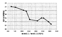
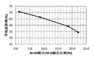
- FIG. 6 is a graph of average reflectance for light with a wavelength of 780 nm to 2500 nm with respect to the M—OH bond / MO bond ratio of silicon compound-coated iron oxide particles obtained by an example of the present invention.
- 5 is a transmission spectrum of a dispersion obtained by dispersing the silicon compound-coated iron oxide particles obtained in Example 1 and Example 1-5 of the present invention and the iron oxide particles obtained in Example 4 in propylene glycol.
- 6 is a graph of average reflectance for light with a wavelength of 780 nm to 2500 nm with respect to the M—OH bond / MO bond ratio of silicon compound-coated iron oxide particles obtained by an example of the present invention.
- 6 is a graph showing the maximum reflectance of light having a wavelength of 400 nm to 620 nm with respect to the M—OH bond / MO bond ratio of the silicon compound-coated iron oxide particles obtained by an example of the present invention.
- 3 is a graph of average reflectance for light with a wavelength of 620 nm to 750 nm with respect to the M—OH bond / MO bond ratio of silicon compound-coated iron oxide particles obtained by an example of the present invention.
- 3 is a graph of hue in the L * a * b * color system with respect to the M—OH bond / MO bond ratio of silicon compound-coated iron oxide particles obtained by an example of the present invention.
- the above silicon compound-coated iron oxide particles with respect to the M—OH bond / MO bond ratio of the silicon compound-coated iron oxide particles obtained in Examples 1, 1-3, 1-4, and 1-5 of the present invention were converted into propylene glycol. It is a graph of the average molar extinction coefficient with respect to the light of wavelength 190nm to 380nm of the dispersion liquid disperse
- FIG. 3 shows the results of reflection spectrum measurement of silicon compound-coated iron oxide particles obtained in Example 1, Example 1-9, and Example 1-10 of the present invention for light having a wavelength of 200 nm to 2500 nm. It is an IR spectrum measurement result of the silicon compound coated iron oxide particles obtained in Example 1 and Example 1-9 of the present invention.
- FIG. 5 is a STEM mapping result of silicon compound-coated zinc oxide particles obtained by coating a part of the surface of the zinc oxide particles obtained in Example 2-4 of the present invention with a silicon compound.
- FIG. 3 is a result of line analysis of silicon compound-coated zinc oxide particles obtained by coating a part of the surface of the zinc oxide particles obtained in Example 2-4 of the present invention with a silicon compound.
- FIG. 4 shows the result of reflection spectrum measurement for light having a wavelength of 200 nm to 780 nm with respect to the M—OH bond / MO bond ratio of silicon compound-coated zinc oxide particles obtained by an example of the present invention.
- Dispersions in which the silicon compound-coated zinc oxide particles obtained in Examples 2, 2-2, 2-3, and 2-4 of the present invention and the zinc oxide particles obtained in Example 5 are dispersed in propylene glycol It is a graph of the molar extinction coefficient. It is a TEM photograph of the silicon compound covering cerium oxide particle which coat
- FIG. 1 is a schematic view of an apparatus used in a method for controlling the M—OH bond / MO bond ratio of oxide particles of the present invention.
- FIG. It is a XRD measurement result of the iron oxide particle obtained in Example 4 of this invention. It is Embodiment 4, and IR measurement results in the range of 4000 cm -1 wave number 50 cm -1 of the obtained iron oxide particles in Example 4-4 of the present invention. It is the result of the waveform separation of IR measurement results in the range of 1250 cm -1 wave number 100 cm -1 of the obtained iron oxide particles in Example 4 of the present invention. It is the result of the waveform separation of IR measurement results in the range of 1250 cm -1 wave number 100 cm -1 of the obtained iron oxide particles in Example 4-4 of the present invention.
- FIG. 4 is a graph of molar extinction coefficient with respect to a measurement wavelength of 190 nm to 780 nm in a dispersion in which the iron oxide particles obtained in Example 4 of the present invention and Examples 4-2 to 4-4 are dispersed in propylene glycol. .
- FIG. 4 is a graph showing an average molar extinction coefficient for light having a wavelength of 190 nm to 380 nm with respect to the M—OH bond / MO bond ratio of the iron oxide particles obtained in Example 4 and Examples 4-2 to 4-4 of the present invention. is there. It is a reflection spectrum measurement result with respect to the light with a wavelength of 200 nm to 2500 nm of the iron oxide particles obtained in Example 4 and Examples 4-2 to 4-4 of the present invention.
- FIG. 4 is a graph of average reflectance for light having a wavelength of 780 nm to 2500 nm with respect to the M—OH bond / MO bond ratio of the iron oxide particles obtained in Example 4 and Examples 4-2 to 4-4 of the present invention. . It is a TEM photograph of the zinc oxide particles obtained in Example 5 of the present invention. 4 is a TEM photograph of zinc oxide particles obtained in Example 5-4 of the present invention. It is a XRD measurement result of the zinc oxide particle obtained in Example 5 of this invention. It is Embodiment 5, and IR measurement results in the range of 4000 cm -1 wave number 50 cm -1 of the obtained zinc oxide particles in Examples 5-4 of the present invention.
- the molar ratio relative to the measurement wavelength of 200 nm to 780 nm is a graph of an extinction coefficient. It is a reflection spectrum measurement result with respect to light with a wavelength of 200 nm to 2500 nm of the zinc oxide particles obtained in Example 5 and Examples 5-2 to 5-4 of the present invention.
- FIG. 5 is a transmission spectrum for light having a wavelength of 200 nm to 780 nm in a dispersion in which the zinc oxide particles obtained in Example 5 and Examples 5-2 to 5-4 of the present invention are dispersed in propylene glycol.
- Example 4 is a TEM photograph of zinc oxide particles obtained in Example 5-6 of the present invention. It is Embodiment 5, and IR measurement results in the range of 4000 cm -1 wave number 50 cm -1 of the obtained zinc oxide particles in Examples 5-6 of the present invention.
- the measurement wavelength is from 200 nm to 780 nm. It is a graph of a molar extinction coefficient. It is a reflection spectrum measurement result with respect to light with a wavelength of 200 nm to 2500 nm of the zinc oxide particles obtained in Example 5 and Examples 5-5 to 5-7 of the present invention.
- 3 is a TEM photograph of zinc oxide particles obtained in Comparative Example 2-1 of the present invention. 4 is a TEM photograph of zinc oxide particles obtained in Comparative Example 3-1 of the present invention. 3 is a TEM photograph of zinc oxide particles obtained in Comparative Example 3-2 of the present invention.
- the oxide particles according to the present invention have a reflectivity, transmittance, molar extinction coefficient, hue, or hue by controlling the ratio of M—OH bonds or M—OH bonds / MO bonds in the oxide particles.
- Oxide particles with controlled color characteristics of saturation for the purpose of using the oxide particles according to the present invention for coatings, painted bodies, compositions intended for application to human skin, etc., or glass
- a film-like oxide composition it is possible not only to impair the design or aesthetics and texture, but also to develop color effectively, so that it can be used effectively on an object to be coated. Or a film-like oxide composition.
- the oxide particles according to the present invention are oxide particles containing a single element or a plurality of different elements other than oxygen or hydrogen obtained by a method such as reaction, crystallization, precipitation, and coprecipitation.
- the element other than oxygen or hydrogen is preferably a metal element or a metalloid element on the chemical periodic table.
- the metalloid element in the present invention is not particularly limited, but preferably, metalloid elements such as Si, Ge, As, Sb, Te, and Se can be exemplified.
- These metals and metalloids may be oxide particles composed of a single element, or complex oxide particles composed of a plurality of elements or complex oxide particles containing a metal element and a metalloid element. Good.
- oxide particles containing different elements When implemented as oxide particles containing different elements, it can also be implemented as a form of the composite oxide particles, and at least a part of the surface of the oxide particles is contained in the oxide particles as described later. It can also be implemented as oxide particles coated with an oxide containing an element different from an element other than oxygen.
- the oxide particles according to the present invention are not limited to those composed only of oxides.
- the present invention can also be carried out including compounds other than oxides to the extent that they do not affect the present invention.
- it can be implemented as oxide particles or composite oxide particles in which a compound other than an oxide is contained in an oxide, or oxide particles in which at least a part of the surface is coated with a compound other than an oxide.
- compounds other than the oxides include hydroxides, hydroxides, nitrides, carbides, various salts such as nitrates and sulfates, and hydrates and organic solvates.
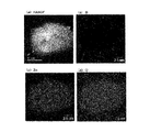
- FIG. 1 is a mapping result using STEM of the silicon oxide-coated iron oxide particles obtained in Example 1-5.
- (a) is a dark field image (HAADF image)
- (b) is a mapping result of silicon (Si)
- (c) is iron (Fe)
- (d) is a mapping result of oxygen (O).
- HAADF image dark field image
- Si silicon
- (c) is iron (Fe)
- (d) is a mapping result of oxygen (O).
- iron and oxygen are detected in the entire particle, and silicon is detected mainly on the surface of the particle.
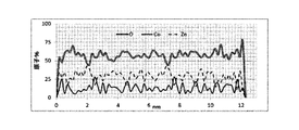
- FIG. 2 is a result of line analysis at a position where a broken line is given in the HAADF image of FIG. 1, and a result showing atomic% (mol%) of an element detected in a line portion from end to end of the particle. It is.
- oxygen and silicon were detected up to both ends of the analysis range in the line analysis, but iron was not detected from the end of the particle to the inside of about several nm, and the surface of iron oxide was detected. It can be seen that is covered with silicon oxide.
- FIG. 3 shows the mapping result using STEM of the silicon oxide-coated iron oxide particles obtained in Example 1 described later
- FIG. 4 shows the result of the line analysis at the position where the broken line is given in the HAADF image of FIG. . As seen in FIGS.
- the particles obtained in Example 1 are different from the particles obtained in Example 1-5 in that the iron oxide particles are not entirely covered with silicon oxide.
- These are silicon oxide-coated iron oxide particles in which a part of the surface of the iron oxide particles is coated with silicon oxide.
- the oxide of the present invention can be implemented as silicon compound-coated oxide particles in which at least a part of the surface of the oxide particles is coated with a silicon compound.
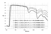
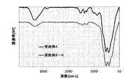
- FIG. 5 shows the FT-IR measurement results of the silicon compound-coated oxide particles obtained in Example 1 and Example 1-5 measured by the total reflection method (ATR method) (hereinafter simply referred to as IR measurement).
- ATR method total reflection method
- IR measurement results of the silicon compound-coated oxide particles in Example 1-5 as compared to IR measurement results of the silicon compound-coated oxide in Example 1, 1650 cm -1 and around 3400cm around -1 And the broad peak in the vicinity of 800 cm ⁇ 1 to 1250 cm ⁇ 1 appear to shift to the high wavenumber side.
- a peak near 3400 cm ⁇ 1 is derived from a hydroxyl group (—OH) containing water
- a peak near 800 cm ⁇ 1 to 1250 cm ⁇ 1 is derived from an M—OH bond.
- the peak containing the peak the peak around 800 cm -1 from the vicinity of 100 cm -1 is believed to peak containing a peak derived from the M-O bond.
- various color characteristics are controlled by controlling the ratio of M—OH bonds or the ratio of M—OH bonds / M—O bonds contained in the oxide particles.
- the M—OH bond / MO bond ratio can be determined from the IR measurement result as an example.
- the M-OH bond ratio or the M-OH bond / MO bond ratio may be measured by a method other than IR measurement.
- XPS X-ray photoelectron spectroscopy
- Solid-state NMR solid nuclear magnetic resonance
- EELS electron energy loss spectroscopy
- M-OH bond 1 can be attributed to a peak derived from the M-OH bond, among the peaks waveform separated from the wave number 100 cm -1 to 800 cm -1, 472Cm around -1 (FIG. 6: MO bond 1) and peaks separated in the vicinity of 592 cm ⁇ 1 (FIG. 6: MO bond 2) can be attributed to peaks derived from the MO bond.
- control over the total area of each peak whose waveform is separated in the region of 1250 cm -1 wave number 100 cm -1 the area ratio of the waveform separated peaks in the M-OH bonds as the ratio of M-OH bonds.
- the area ratio of the peaks waveform-separated into the MO bond is controlled as the ratio of the MO bond
- the ratio of the MO bond to the MO bond is the ratio of the MO bond / M- It is preferable to control the color characteristics of the oxide particles by controlling the O bond ratio.
- the assignment of each peak separated from the waveform to the M—OH bond or the M—O bond can be performed from known literatures and databases.
- the peak having the largest area ratio of the M—O bond peak to the total area of each peak separated from the waveform is used.
- the area ratio of MO bond to the total area of each peak separated by the waveform is It is preferable to derive the M—OH bond / MO bond using the largest peak.
- the M—OH bond when a plurality of M—O bond peaks composed of different types of M such as Fe and Si appear, and when a plurality of M—OH bonds consisting of different types of M appear, the M—OH bond Alternatively, by calculating the area ratio at each of a plurality of different peaks with respect to the MO bond and setting the total as the ratio of the M-OH bond or the ratio of the MO bond, the M-OH bond / MO It is preferred to derive a bond. In the figure, peaks that cannot be attributed are constituent peaks.
- Example 1-5 shows the total area of each peak separated in the M-OH bond with respect to the total peak component of the waveform separated peak. It can be seen that the ratio is small. That is, the ratio of M—OH bonds contained in the oxide particles of Example 1-5 or the ratio of M—OH bonds / M—O bonds is equal to the ratio of M—OH bonds contained in the oxide particles of Example 1 or It was shown that the ratio was lower than the M—OH bond / MO bond ratio.
- the ratio coupling is the ratio of the M-OH bond to the ratio of M-O bond is the total area of the M-O bond, which is waveform separation below wavenumber 100 cm -1 or more 800 cm -1 M-OH bonds / M It has been found that the color characteristics of the oxide particles can be controlled by controlling the ratio to -O bond ratio (M-OH bond / MO bond ratio [%]).
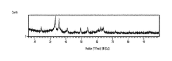
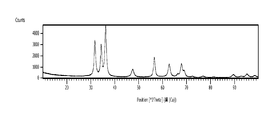
- FIG. 8 shows the XRD measurement results of the oxide particles obtained in Example 1-5. As can be seen in FIG. 8, no peak is observed other than the peak derived from ⁇ -Fe 2 O 3 . Also in Example 1 above, no peaks other than those derived from ⁇ -Fe 2 O 3 were observed in the XRD measurement results (not shown). Nevertheless, in the IR measurement results, the above M-OH Since the peak derived from the bond was detected, the M—OH bond is mainly present on the surface of the oxide particle rather than the inside of the particle. I think that was not detected. Further, the XRD measurement results show that the silicon compound confirmed by the IR measurement contains an amorphous substance.
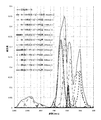
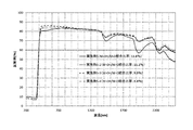
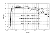
- FIG. 9 shows the reflection spectrum of the oxide particles obtained in Example 1 and Examples 1-2 to 1-5 with respect to light having a wavelength of 200 nm to 2500 nm.
- the reflectance with respect to light in the near-infrared region of wavelengths from 780 nm to 2500 nm is such that the silicon compound-coated oxide particles obtained in Example 1-5 are more than the silicon compound-coated oxide particles obtained in Example 1. I understand that it is expensive.
- M-OH ratio calculated by waveform separation of the peaks in the range of 1250 cm -1 wave number 100 cm -1 ([%]) and M-OH bonds / M-O bond ratio ([%] ) Is smaller in the order of Example 1-5 ⁇ 1-4 ⁇ 1-3 ⁇ 1-2 ⁇ 1, and the average reflectance with respect to light having a wavelength of 780 nm to 2500 nm is greater than that of Example 1-5>1-4> 1- 3>1-2> 1 in order.
- the average reflectance with respect to a light beam having a wavelength of 780 nm to 2500 nm is a simple average value of the reflectances of all the measurement wavelengths in the wavelength region of the wavelength 780 nm to 2500 nm.
- the oxide particles of the present invention have an oxidation rate with controlled average reflectance for light having a wavelength of 780 nm to 2500 nm, which is one of the color characteristics, by controlling the ratio of M—OH bonds contained in the oxide particles.
- the oxide particles having an average reflectance increased with respect to light having a wavelength of 780 nm to 2500 nm. Preferably there is.
- the molar extinction coefficient can be calculated by the following formula 1 from the absorbance in the UV-visible absorption spectrum measurement and the molar concentration of the substance to be measured in the measurement sample.
- ⁇ A / (c ⁇ l) (Formula 1)
- ⁇ is a constant specific to the substance, which is called a molar extinction coefficient, and is the absorbance of a 1 mol / L dispersion having a thickness of 1 cm. Therefore, the unit is L / (mol ⁇ cm).
- A is the absorbance in the UV-visible absorption spectrum measurement
- c is the molar concentration (mol / L) of the sample.
- l is a length (optical path length) (cm) through which light is transmitted, and is usually a thickness of a cell when an ultraviolet-visible absorption spectrum is measured.
- a simple molar extinction coefficient at each of the measurement wavelengths in the measurement wavelength region of a wavelength of 190 nm (200 nm) to 380 nm was calculated and evaluated as the average molar extinction coefficient.
- the average reflectance with respect to a light beam having a wavelength of 780 nm to 2500 nm is a simple average value of the reflectance at each of all measurement wavelengths in a reflection spectrum in a wavelength region of a wavelength of 780 nm to 2500 nm.
- the average transmittance from wavelengths 380 nm to 780 nm is a simple average of transmittances at all measurement wavelengths in the transmission spectrum in the wavelength region from wavelengths 380 nm to 780 nm.
- These average molar extinction coefficient, average reflectance, and average transmittance are not limited to the above wavelength region, and the wavelength region to be averaged can be appropriately set according to the target color characteristics.
- the L * a * b * color system is one of uniform color spaces
- L * is a value representing brightness. The larger the value, the brighter the color.
- a * and b * represent chromaticity.
- the color system is not limited to the L * a * b * color system.
- the color characteristics may be evaluated using another color system such as an XYZ system.
- the method for controlling the M-OH bond ratio is not particularly limited, but it is preferable to control the M-OH bond ratio by changing the functional groups contained in the oxide particles.
- the functional group changing treatment is a reaction using a conventionally known substitution reaction, addition reaction, elimination reaction, dehydration reaction, condensation reaction, reduction reaction, oxidation reaction, or the like on the functional group contained in the oxide particles. It is possible to control the ratio of the M-OH bond by the method of performing the above. In controlling the ratio of the M—OH bond, the M—OH bond / MO bond ratio may be increased or decreased.
- a carboxylic acid such as acetic anhydride is allowed to act on the M—OH bond contained in the oxide particles, so that OH from the carboxyl group (—COOH) is changed from the hydroxyl group (—OH) in the M—OH group.
- Examples include a method of controlling the ratio of M-OH bonds or the ratio of M-OH bonds / MO bonds by esterification achieved by dehydration / condensation reaction in which H is eliminated.
- a method using a mixed acid anhydride, acid halide or the like, or a dehydrating agent such as carbodiimide, or the like can also be used.
- an alkyl halide, aryl halide or heteroaryl halide is allowed to act on the M-OH group, preferably in the presence of an acid catalyst, so that dehydration results in dehydration of the ether between the alkyl halide or the like and M.
- the ratio of the M-OH bond or the M-OH bond / Si-O bond is determined by a method of generating a bond or a method of generating an (thio) urethane bond by allowing isocyanate or thioisocyanate to act on the M-OH. It is also possible to control the ratio.
- the ratio of bond / MO bond may be controlled.
- the present invention is not limited to the production of new bonds by directly acting other substances or functional groups on M-OH bonds or M-O bonds.
- carboxylic acids contained in particles By controlling the ratio of M—OH bond or the ratio of M—OH bond / M—O bond by the method of acting carbodiimide, or by acting ethylene oxide or the like on M—OH bond, It is also possible to control the ratio of the M-OH bond or the ratio of M-OH bond / MO bond by a method such as producing a bond such as (CH 2 ) 2 -OH or allowing epihalohydrin to act. is there.
- the M-OH bond ratio or the M-OH bond / MO bond ratio can be controlled by a method in which hydrogen peroxide or ozone is allowed to act on the oxide particles.
- the ratio of the M-OH bond or the M-OH bond / MO is determined by a method for precipitating the oxide particles, a method of controlling pH, or the like. It is also possible to control the coupling ratio. As an example of the dehydration reaction, the above ratio can be controlled by a method of heat-treating the oxide particles.
- the M-OH bond ratio or the M-OH bond / MO bond ratio by the method of heat-treating the oxide particles, it can be carried out by dry heat treatment, and the oxide particles are dispersed in a dispersion medium. It can also be carried out by heat treatment in the state of the dispersion.
- the ratio may be controlled by dispersing oxide particles in a target solvent, adding a substance containing a functional group to the dispersion, and performing a treatment such as stirring.
- the ratio may be controlled by performing a treatment such as stirring in the dispersion containing the oxide particles.
- a slurry for performing a method of removing impurities from a slurry containing oxide particles by dispersing the particles and processing by cross-flow membrane filtration by constructing a device in which the dispersing device and the filtration membrane are continuous. It can also be implemented by changing the temperature or the temperature of the cleaning liquid used for the cross flow.
- the primary particles of the oxide particles in particular, the surface of each primary particle can be uniformly modified, so that the M—OH contained in the oxide particles in the present invention is used.
- the control of the ratio of coupling and the control of the color characteristics can be performed more strictly and uniformly.
- pH adjusters such as an acidic substance or a basic substance, in at least one of the various solutions in this invention, and a solvent. You may adjust by changing the flow volume at the time of mixing the fluid containing a raw material liquid, and the fluid containing an oxide precipitation solvent.
- the method for changing the functional group contained in the oxide particles according to the present invention is not particularly limited.
- the oxide particles may be dispersed in a target solvent, and a substance containing a functional group may be added to the dispersion and subjected to a treatment such as stirring, or a fluid containing oxide particles and a substance containing a functional group may be included. You may implement by mixing a fluid using the above-mentioned microreactor.
- the substance containing a functional group is not particularly limited, but is a substance containing a functional group that can be substituted for the hydroxyl group contained in the oxide particles, and an acylating agent such as acetic anhydride or propionic anhydride; dimer sulfate or dimethyl carbonate And silane coupling agents such as chlorotrimethylsilane and methyltrimethoxysilane.
- an acylating agent such as acetic anhydride or propionic anhydride
- silane coupling agents such as chlorotrimethylsilane and methyltrimethoxysilane.
- the M-OH bond ratio can also be controlled by a method in which hydrogen peroxide or ozone acts on oxide particles.
- a method for causing hydrogen peroxide or ozone to act on oxide particles is not particularly limited.
- the oxide particles may be dispersed in a target solvent, and a solution such as hydrogen peroxide or ozone or an aqueous solution containing them may be added to the dispersion, followed by a treatment such as stirring, or a fluid containing oxide particles. You may implement by mixing the fluid containing hydrogen peroxide or ozone using the above-mentioned microreactor.
- the dispersion may be implemented as a liquid dispersion in which oxide particles are dispersed in a liquid dispersion medium such as water, an organic solvent, or a resin, or a coating prepared using a dispersion containing oxide particles. It can also be implemented as a film-like dispersion.
- the oxide particles of the present invention are used in a multilayer coating film and a high-design multilayer coating film, the oxide particles are converted into the oxide particles by a method such as heat treatment after the oxide particles are converted into the multilayer coating film or multilayer coating film. Since the color characteristics of the oxide particles can be controlled by controlling the contained M—OH bond / MO bond ratio, it is suitable for the reduction of the number of steps and the strict control of the color characteristics.
- reflected light is increased by increasing the difference between highlight and shade for a specific color.
- the intensity of the light changes greatly depending on the observation angle, and a sense of depth and denseness is realized.
- the coating film containing the substance having the near-infrared reflective property increases the transparency of the coating film as the oxide particle dispersion as the molar absorption coefficient in the ultraviolet region, which is the ability to absorb ultraviolet rays of the oxide particles, is larger.
- the haze value can be reduced by reducing the amount of oxide particles used.
- laminated glass for bonding an intermediate film such as a resin between a plurality of plate glasses, a film used for glass of a building, a sheet to be affixed to glass, or a film-like composition it is suitable for use as a transparent material composition by dispersing oxide particles such as silicon compound-coated zinc oxide particles in a transparent material such as glass or transparent resin, and for absorbing ultraviolet rays or reflecting near infrared rays.
- oxide particles such as silicon compound-coated zinc oxide particles
- a transparent material such as glass or transparent resin
- the transmission property to visible light can be enhanced, it can be suitably used as a composition for transparent material for UV protection and near infrared protection purposes.
- the oxide particles are dispersed in glass, transparent resin or the like to form a film or a transparent material, and then the functional group is changed by heat treatment or the like, thereby changing the M contained in the oxide particles. It is also possible to control the color characteristics of the oxide particles by controlling the bonding ratio of —OH, which is suitable for reducing the number of steps and controlling the strict color characteristics in the same manner as the above-mentioned laminated coating film.
- the primary particle diameter of the oxide particles is preferably 1 nm or more and 100 nm or less, and more preferably 1 nm or more and 50 nm or less.
- the oxide particles having a primary particle size of 100 nm or less have a primary particle size of 100 nm.
- the surface area is increased compared to the oxide particles that exceed it, and the transmission characteristics and absorption characteristics of the oxide particles can be controlled by controlling the M-OH bond ratio or the M-OH bond / MO bond ratio of the oxide particles.
- the oxide particles are oxide particles in which at least a part of the surface of the particles is coated like the silicon compound-coated iron oxide particles
- the average primary particles of the oxide particles before the coating It is preferable that the ratio of the average primary particle diameter of the oxide particles after coating with the compound with respect to the diameter is 100.5% or more and 190% or less. If the coating of the compound on the oxide particles is too thin, the effect on the color characteristics of the oxide particles coated with the compound may not be exhibited, so the average primary particles of the oxide particles after coating with the compound
- the diameter is preferably 100.5% or more of the average primary particle diameter of the oxide particles, and it is difficult to control the color characteristics when the coating is too thick or when coarse aggregates are coated.
- the average primary particle diameter of the oxide particles after coating with the compound is preferably 190% or less of the average primary particle diameter of the oxide particles.
- the oxide particles coated with the compound according to the present invention may be core-shell type compound-coated oxide particles in which the entire surface of the oxide particles serving as the core is uniformly coated with the compound.
- the compound-coated oxide particles are preferably compound-coated oxide particles in which a plurality of oxide particles are not aggregated and at least a part of the surface of a single oxide particle is coated with a compound. Further, it may be a compound-coated oxide particle in which at least a part of the surface of an aggregate obtained by aggregating a plurality of oxide particles is coated with a compound.
- the compound covering at least a part of the surface of the oxide is preferably a silicon compound, more preferably a silicon oxide, and even more preferably an amorphous silicon oxide.
- a silicon compound By including an amorphous silicon oxide in the silicon compound, it is possible to strictly control color characteristics such as reflectance, transmittance, molar extinction coefficient, hue, and saturation of the silicon compound-coated oxide particles.
- the silicon compound is a crystalline silicon oxide, it is extremely difficult to make M—OH (Si—OH) exist, and thus it may be difficult to control the color characteristics of the present invention.
- 2009-112892 includes a stirring tank having an inner peripheral surface having a circular cross-sectional shape, and a stirring tool attached with a slight gap from the inner peripheral surface of the stirring tank.
- the stirring tank includes at least two fluid inlets and at least one fluid outlet, and one of the fluid inlets includes a first of the reactants among the fluids to be processed.
- the fluid to be treated is introduced into the agitation tank, and the second fluid to be treated containing one of the reactants different from the reactant from one place other than the above among the fluid inlets,
- the fluid to be treated is introduced into the stirring tank from a different flow path, and at least one of the stirring tank and the stirring tool is rotated at a high speed with respect to the other so that the fluid to be treated is in a thin film state.
- an oxide raw material liquid containing at least an oxide particle raw material and an oxide precipitation solvent containing at least an oxide precipitation material for precipitating the oxide particles are prepared. It is preferable to use a method of producing oxide particles by a method such as reaction, crystallization, precipitation, and coprecipitation in a mixed fluid in which an oxide raw material liquid and an oxide precipitation solvent are mixed. As described above, when the oxide particles are produced by a method such as reaction, crystallization, precipitation, coprecipitation, etc., particles in which the M—OH bond ratio is controlled to a predetermined value may be produced. .
- the raw material for the oxide particles in the present invention is not particularly limited. Any method can be used as long as it becomes an oxide by a method such as reaction, crystallization, precipitation, and coprecipitation.
- a simple substance of a metal or a semimetal, or a compound can be illustrated.
- the above metal or metalloid compounds are collectively referred to as compounds.
- a metal or metalloid salt and oxide, hydroxide, hydroxide oxide, nitride, carbide, complex, organic salt, organic complex, organic compound or those compounds will be described. Hydrates, organic solvates and the like can be mentioned.
- Metal or metalloid salts are not particularly limited, but metal or metalloid nitrates or nitrites, sulfates or sulfites, formates or acetates, phosphates or phosphites, hypophosphites And chlorides, oxy salts, acetylacetonate salts or hydrates thereof, organic solvates, and the like, and examples of the organic compound include metal or semimetal alkoxides. As described above, these metal or metalloid compounds may be used alone or as a mixture of two or more.
- the oxide particle is an oxide particle containing a silicon compound, such as a silicon compound-coated oxide
- the raw material of the silicon compound is a silicon oxide or hydroxide, or other compound such as a silicon salt or an alkoxide. And their hydrates.
- silicates such as sodium silicate, phenyltrimethoxysilane, methyltrimethoxysilane, methyltriethoxysilane, 3-glycidoxypropyltrimethoxysilane, 3-trifluoropropyl-trimethoxysilane, Methacryloxypropyltriethoxysilane, tetramethoxysilane (TMOS), tetraethoxysilane (TEOS), and oligomeric condensates of TEOS, such as ethyl silicate 40, tetraisopropylsilane, tetrapropoxysilane, tetraisobutoxysilane, tetrabutoxysilane , And similar materials.
- TMOS tetramethoxysilane
- TEOS tetraethoxysilane
- oligomeric condensates of TEOS such as ethyl silicate 40, tetraisoprop
- siloxane compounds bis (triethoxysilyl) methane, 1,9-bis (triethoxysilyl) nonane, diethoxydichlorosilane, triethoxychlorosilane, and the like may be used as a raw material for the silicon compound.
- oxide particles in the present invention are silicon compound-coated oxide particles, it is preferable that silicon is contained from 2% to 80% with respect to elements other than oxygen constituting the oxide particles to be coated, More preferably 5 to 50% is contained.
- the above-mentioned silicon compound raw material can be used by appropriately selecting the amount and type of use depending on the type of target oxide particles.
- the oxide particle raw material when the raw material of the oxide particle or silicon compound is solid, the oxide particle raw material is melted or mixed or dissolved in a solvent described later (including molecularly dispersed state). It is preferable to use in. Even when the raw material of the oxide particles is a liquid or a gas, it is preferably used in a state of being mixed or dissolved in a solvent described later (including a state of molecular dispersion).
- the oxide depositing substance is not particularly limited as long as it is a substance capable of depositing the oxide particle raw material contained in the oxide raw material liquid as oxide particles.
- an acidic substance or a basic substance is used. Can do. It is preferable to use at least the oxide depositing substance in a state of being mixed, dissolved, and molecularly dispersed in a solvent described later.
- Examples of basic substances include metal hydroxides such as sodium hydroxide and potassium hydroxide, metal alkoxides such as sodium methoxide and sodium isopropoxide, amine compounds such as triethylamine, diethylaminoethanol and diethylamine, and ammonia. It is done.
- metal hydroxides such as sodium hydroxide and potassium hydroxide
- metal alkoxides such as sodium methoxide and sodium isopropoxide
- amine compounds such as triethylamine, diethylaminoethanol and diethylamine, and ammonia. It is done.
- Acidic substances include inorganic acids such as aqua regia, hydrochloric acid, nitric acid, fuming nitric acid, sulfuric acid and fuming sulfuric acid, and organic acids such as formic acid, acetic acid, chloroacetic acid, dichloroacetic acid, oxalic acid, trifluoroacetic acid, trichloroacetic acid and citric acid. Examples include acids.
- the basic substance and the acidic substance can be used for precipitating the oxide particles, and as described above, the pH adjustment for controlling the ratio of M—OH bonds contained in the oxide particles. It can also be used as an agent.
- solvent examples of the solvent used for the oxide raw material liquid and the oxide precipitation solvent include water, an organic solvent, and a mixed solvent composed of a plurality of them.
- examples of the water include tap water, ion-exchanged water, pure water, ultrapure water, RO water (reverse osmosis water), and the organic solvents include alcohol compound solvents, amide compound solvents, ketone compound solvents, ether compounds.
- examples include solvents, aromatic compound solvents, carbon disulfide, aliphatic compound solvents, nitrile compound solvents, sulfoxide compound solvents, halogen compound solvents, ester compound solvents, ionic liquids, carboxylic acid compounds, and sulfonic acid compounds.
- Each of the above solvents may be used alone or in combination.
- examples of the alcohol compound solvent include monohydric alcohols such as methanol and ethanol, polyols such as ethylene glycol and propylene glycol, and the like.
- dispersants and surfactants may be used according to the purpose and necessity as long as the production of oxide particles is not adversely affected.
- a dispersing agent and surfactant the various commercially available products generally used, a product, or what was newly synthesize
- examples include anionic surfactants, cationic surfactants, nonionic surfactants, dispersants such as various polymers, and the like. These may be used alone or in combination of two or more.
- Said surfactant and dispersing agent may be contained in at least any one fluid of an oxide raw material liquid and an oxide precipitation solvent. Moreover, said surfactant and dispersing agent may be contained in another fluid different from the oxide raw material liquid and the oxide precipitation solvent.
- the ratio of the M—OH bond that is a bond between a single or different element (M) other than oxygen or hydrogen contained in the oxide particles and a hydroxyl group (OH) is controlled.
- preparing untreated oxide particles having a predetermined primary particle size to be controlled the ratio of M-OH bond or M-OH bond / MO bond ratio;
- the treatment can be performed separately from the step of subjecting untreated oxide particles to a treatment for controlling the ratio of M—OH bonds or the ratio of M—OH bonds / MO bonds.
- the ratio of the M—OH bond or the M—OH bond / MO bond ratio is controlled to a predetermined value. It is also possible to produce particles.
- the coating oxide composition or the film-like oxide composition of the present invention is not particularly limited in addition to those described in JP-A No. 2014-042891 and JP-A No. 2014-042992.
- the present invention can be applied to coating or film-like compositions for various coating purposes such as paints and water-based paints.
- the coating oxide composition may contain pigments, dyes, wetting agents, dispersants, anti-splitting agents, leveling agents, viscosity modifiers, anti-skinning agents, anti-gelling agents, anti-gelling agents as necessary.
- Additives such as a foaming agent thickener, an anti-sagging agent, an antifungal agent, an ultraviolet absorber, a film forming aid, a surfactant, and a resin component can be further included depending on the purpose.
- Resin components for coating purposes include polyester resin, melamine resin, phenol resin, epoxy resin, vinyl chloride resin, acrylic resin, urethane resin, silicon resin, fluorine resin, etc. It can be exemplified.
- the applied material to which the coating material containing the coating oxide composition of the present invention is applied may be a single-layer coated material composed of a single coating composition, and Japanese Patent Application Laid-Open No. 2014-042891.
- it may be a multi-layered coating composition composed of a plurality of coating compositions, as in the case of laminated coatings as described in JP-A-2014-042992, and is also included in coatings containing pigments. It can also be carried out, or it can be carried out by being included in a paint such as a clear paint.
- An oxide composition for coating, a film-like oxide composition, or a transparent material composition according to the present invention comprises oxide powder; a dispersion in which oxide particles are dispersed in a liquid dispersion medium; and glass or transparent It includes oxide particles such as a dispersion in which oxide particles are dispersed in a solid such as a resin (or liquid before solidification).
- the oxide particles contained in the coating oxide composition or the film-like oxide composition may be composed of one oxide particle, and are composed of an aggregate in which a plurality of oxide particles are aggregated. Or a mixture of both. When composed of an aggregate in which a plurality of oxide particles are aggregated, the size of the aggregate is preferably 50 nm or less.
- the oxide composition may be used in combination with various pigments in a cosmetic or paint, or may be overcoated on a coating film. Furthermore, oxide particles can also be used as a single pigment.
- liquid dispersion media include tap water, distilled water, RO water (reverse osmosis water), pure water, ultrapure water and the like; alcohol solvents such as methanol, ethanol, isopropyl alcohol; propylene glycol, ethylene glycol, Polyhydric alcohol solvents such as diethylene glycol and glycerol; ester solvents such as ethyl acetate and butyl acetate; aromatic solvents such as benzene, toluene and xylene; ketone solvents such as acetone and methyl ethyl ketone; nitrile solvents such as acetonitrile; Silicone oil, vegetable oil, wax and the like can be mentioned. These may be used alone or in combination.
- Color of coating composition or film-like composition It does not specifically limit as a color of transparent materials, such as a coated material, a film, or glass,
- the oxide composition for coating of this invention or a film-form composition can be used with respect to the target hue.
- White color, gray color, black color for example, colors with whiteness of 10 to blackness in Munsell color system, red colors, for example, colors with RP to YR hue in the Munsell hue ring, yellow to green
- a color with a Y to BG hue in the Munsell hue ring or a color from blue to purple, for example a color with a B to P pigment in the Munsell hue ring (each including a metal color)
- blend suitably in the coating composition obtained, it is not limited to this, The color of another hue may be sufficient.
- the coating composition containing the oxide particles of the present invention particularly in the coating film or the top coat of the coated body exhibiting those colors, it is possible to remarkably reduce the color development of each color. This is suitable because the design properties can be improved.
- Various pigments and dyes can be used as the pigments and dyes included in the coating composition as necessary. For example, all pigments and dyes registered in the color index can be used. Among them, for example, C.I. I. Pigments and dyes classified as Pigment Green; C.I. I. Pigments and dyes classified as Pigment Blue; C.1. I. Pigments and dyes classified as Pigment White; C.I. I. Pigments and dyes classified as Pigment Yellow; for pigments and dyes constituting red, C.I.
- the oxide composition of this invention can also be mix
- the color saturation is higher, and for example, it is used for laminated coating as described in JP-A-2014-042891 and JP-A-2014-042992. In this case, it is possible to form a coating material having a large difference between the highlight and the shade in the case, and it is possible to obtain a sharp metal texture by increasing the jetness without causing white blur in the shade.
- the oxide particles in a film-like composition for use in a transparent substrate such as glass used in buildings, vehicles, displays, etc. it can be shielded by effectively absorbing ultraviolet rays, so It can improve safety, suppress the decomposition of organic matter in buildings and vehicles, and can be blocked by effectively reflecting near-infrared rays, so it can suppress high temperatures in buildings and vehicles, and against visible light
- a film or glass with a high transparency can be obtained, which is preferable.
- the present invention will be described in more detail with reference to examples, but the present invention is not limited to these examples.
- the pure water in the following examples used pure water having a conductivity of 0.86 ⁇ S / cm (measurement temperature: 25 ° C.) unless otherwise specified.
- sample preparation for TEM observation and sample preparation for STEM observation Part of the wet cake sample of oxide particles obtained in the examples was dispersed in propylene glycol, and further diluted 100 times with isopropyl alcohol (IPA). The obtained diluted solution was dropped onto a collodion film or a microgrid and dried to obtain a sample for TEM observation or a sample for STEM observation.
- IPA isopropyl alcohol
- TEM-EDS analysis Transmission electron microscope and energy dispersive X-ray analyzer: TEM-EDS analysis
- an energy dispersive X-ray analyzer a transmission electron microscope equipped with JED-2300 (manufactured by JEOL Ltd.), JEM-2100 (JEOL Ltd.) Made).
- the acceleration voltage was set to 80 kV and the observation magnification was set to 25,000 times or more.
- the particle diameter was calculated from the distance between the maximum outer circumferences of the oxide particles observed by TEM, and the average value (average primary particle diameter) of the results of measuring the particle diameter for 100 particles was calculated.
- TEM-EDS the molar ratio of the element components constituting the oxide in the oxide particles was calculated, and the average value of the results of calculating the molar ratio for 10 or more particles was calculated.
- STEM-EDS analysis For mapping and quantification of elements contained in oxide particles by STEM-EDS analysis, an atomic resolution analytical electron microscope equipped with an energy dispersive X-ray analyzer, Centurio (manufactured by JEOL Ltd.), JEM-ARM200F (Manufactured by JEOL Ltd.) was used. The observation conditions were an acceleration voltage of 80 kV, an observation magnification of 50,000 times or more, and analysis using a beam diameter of 0.2 nm in diameter.
- X-ray diffraction measurement For X-ray diffraction (XRD) measurement, a powder X-ray diffraction measurement device EMPYREAN (Spectris Co., Ltd. PANalytical Division) was used. The measurement conditions were a measurement range: 10 to 100 [° 2 Theta] Cu counter cathode, tube voltage 45 kV, tube current 40 mA, and scanning speed 0.3 ° / min. XRD measurement was performed using the dry powder of the oxide particles obtained in each Example.
- EMPYREAN Spectris Co., Ltd. PANalytical Division
- FT-IR measurement For the FT-IR measurement, a Fourier transform infrared spectrophotometer, FT / IR-6600 (manufactured by JASCO Corporation) was used. The measurement conditions are a resolution of 4.0 cm ⁇ 1 and an integration count of 1024 using the ATR method in a nitrogen atmosphere. Waveform separation of the peaks of the infrared absorption wave number spectrum 100 cm -1 from 1250 cm -1, using the FT / IR-6600 spectrum analysis program supplied with the control software, the residual sum of squares of 0.01 or less and Curve fitting was performed. It measured using the dry powder of the oxide particle obtained in the Example.
- Transmission spectrum, absorption spectrum, reflection spectrum, hue and saturation For the transmission spectrum, absorption spectrum, reflection spectrum, hue and saturation, an ultraviolet-visible near-infrared spectrophotometer (product name: V-770, manufactured by JASCO Corporation) was used.
- the measurement range of the transmission spectrum was 190 nm to 800 nm, or 200 nm to 800 nm
- the measurement range of the absorption spectrum was 190 nm to 800 nm, or 200 nm to 800 nm
- the sampling rate was 0.2 nm
- the measurement speed was low.
- the transmittance at a plurality of measurement wavelengths was simply averaged to obtain an average transmittance.
- the molar extinction coefficient is obtained by measuring the absorption spectrum, calculating the molar extinction coefficient at each measurement wavelength from the absorbance obtained from the measurement results and the oxide concentration of the dispersion, the measurement wavelength on the horizontal axis, and the molar extinction coefficient on the vertical axis. It was set as the graph which described. For the measurement, a liquid cell having a thickness of 1 cm was used. Further, the molar extinction coefficient at a plurality of measurement wavelengths from 190 nm (200 nm) to 380 nm was simply averaged to calculate the average molar extinction coefficient.
- the reflection spectrum is measured from 200 nm to 2500 nm, the sampling rate is 2.0 nm, the measurement speed is medium speed, the measurement method is a double beam photometry method, and total reflection measurement is performed to measure regular reflection and diffuse reflection. It was.
- a standard white plate product name: Spectralon (trademark), manufactured by Labsphere) was used for background measurement (baseline setting) when measuring powder.
- the reflection spectrum was measured using the dry powder of silicon oxide-coated iron oxide particles obtained in each example. For a specific wavelength region, the reflectance at a plurality of measurement wavelengths was simply averaged to obtain an average reflectance. Hue and saturation are based on the results of reflection spectrum measurement.
- the color system is L * a * b * color system
- the visual field is 2 (deg)
- the light source is D65-2
- the color matching function is JIS Z 8701: 1999
- the data interval Is 5 nm
- the hue H b * / a *
- saturation C ⁇ ((a * ) 2 + (b * ) 2 ) from the obtained values of L * , a * , b * Calculated using the formula.
- Example 1 describes silicon compound-coated iron oxide particles in which at least a part of the surface of iron oxide particles is coated with a silicon compound as oxide particles.
- Claremix product name: CLM-2.2S, manufactured by M Technique Co., Ltd.
- an oxide raw material liquid liquid A
- an oxide precipitation solvent liquid B
- a silicon compound raw material liquid C liquid
- the mixture was homogeneously mixed by stirring for a minute to prepare an oxide raw material liquid. Moreover, based on the prescription
- a silicon compound raw material liquid was prepared by mixing homogeneously.
- the substances represented by the chemical formula and abbreviations set forth in Table 1 97wt% H 2 SO 4 is concentrated sulfuric acid (manufactured by Kishida Chemical Co., Ltd.), NaOH is (manufactured by Kanto Chemical Co., Inc.) sodium hydroxide, TEOS tetraethylorthosilicate (manufactured by Wako Pure Chemical Industries, Ltd.), Fe (NO 3) 3 ⁇ 9H 2 O was used iron nitrate nonahydrate (manufactured by Kanto Chemical Co., Inc.).
- the prepared oxide raw material liquid, oxide precipitation solvent, and silicon compound raw material liquid were mixed using the fluid treatment apparatus described in Patent Document 7 by the present applicant.
- the fluid treatment device described in Patent Document 7 is the device described in FIG. 1B of the publication, and the openings d20 and d30 of the second and third introduction portions are formed in a ring shape.
- a disc having a concentric ring shape surrounding the central opening of the processing surface 2 was used.
- the oxide raw material liquid is introduced as the liquid A from the first introduction part d1 between the processing surfaces 1 and 2, and the processing part 10 is operated at a rotational speed of 1130 rpm while the oxide precipitation solvent is used as the liquid B.
- a silicon compound raw material liquid was introduced as a C liquid between the processing surfaces 1 and 2 from the third introduction part d3 and mixed with a mixed fluid containing iron oxide particles serving as a core in the thin film fluid.
- a silicon compound is deposited on the surface of the iron oxide particles as a core, and a discharge liquid containing silicon compound-coated iron oxide particles (hereinafter, silicon compound-coated iron oxide particle dispersion) is discharged from between the processing surfaces 1 and 2 of the fluid processing apparatus. It was discharged.
- the discharged silicon compound-coated iron oxide particle dispersion was collected in a beaker b via a vessel v.
- Table 2 shows the operating conditions of the fluid treatment apparatus, the average primary particle diameter calculated from the TEM observation results of the obtained silicon compound-coated iron oxide particles, and the Si / Fe molar ratio calculated from the TEM-EDS analysis. It shows with the calculated value calculated from the prescription of B liquid and C liquid, and an introduction flow rate.
- the introduction temperature (liquid supply temperature) and the introduction pressure (liquid supply pressure) of the liquid A, liquid B and liquid C shown in Table 2 are sealed introduction paths (first introduction part) leading to the processing surfaces 1 and 2.
- a model D-51 pH meter manufactured by HORIBA, Ltd. was used for pH measurement. Before introducing the A liquid, the B liquid, and the C liquid into the fluid processing apparatus, the pH was measured at room temperature. In addition, it is difficult to measure the pH of the mixed fluid immediately after mixing the oxide raw material liquid and the oxide precipitation solvent, and the pH immediately after mixing the fluid containing the core oxide particles and the silicon compound raw material liquid. The pH of the silicon compound-coated iron oxide particle dispersion liquid discharged from the apparatus and collected in the beaker b was measured at room temperature.
- a dry powder and a wet cake sample were prepared from the silicon compound-coated iron oxide particle dispersion liquid discharged from the fluid treatment apparatus and collected in the beaker b.
- the production method was carried out in accordance with a conventional method of this type of treatment.
- the discharged silicon compound-coated iron oxide particle dispersion was recovered, and the supernatant was removed by settling silicon compound-coated iron oxide particles, Washing with 100 parts by weight of pure water and sedimentation were repeated three times, followed by washing with pure water and sedimentation three times to wash the silicon compound-coated iron oxide particles, and finally obtained.
- a part of the wet cake of silicon compound-coated iron oxide particles was dried at ⁇ 0.10 MPaG at 25 ° C. for 20 hours to obtain a dry powder. The rest was used as a wet cake sample.
- FIG. 3 shows the mapping result using STEM of the silicon compound-coated iron oxide particles obtained in Example 1
- FIG. 4 shows the result of line analysis at the position where the broken line is applied in the HAADF image of FIG.
- the silicon compound-coated iron oxide particles obtained in Example 1 also include particles that are not entirely covered with the silicon compound. Silicon compound-coated iron oxide particles partially coated with a silicon compound were observed.
- Example 1 The silicon compound-coated iron oxide particles obtained in Example 1 were subjected to a dehydration reaction by heat treatment using an electric furnace as a treatment for changing the functional group contained in the silicon compound-coated iron oxide particles.
- the heat treatment conditions were as follows: Example 1: Untreated, Example 1-2: 200 ° C., Example 1-3: 400 ° C., Example 1-4: 600 ° C., Example 1-5: 800 ° C. The time is 30 minutes at each heat treatment temperature.
- FIG. 1 shows the mapping result of the silicon compound-coated iron oxide obtained in Example 1-5 using STEM
- FIG. 2 shows the result of line analysis at the position where the broken line is given in the HAADF image of FIG.
- the silicon compound-coated iron oxide particles obtained in Example 1-5 were observed as iron oxide particles covered with the silicon compound as a whole.
- FIG. 5 shows IR measurement results of the silicon compound-coated iron oxide particles obtained in Example 1 and Example 1-5, measured by the ATR method. IR measurement results of the silicon compound-coated oxide particles in Example 1-5 as compared to IR measurement results of the silicon compound-coated oxide in Example 1, 1650 cm -1 and around 3400cm around -1 And the broad peak in the vicinity of 800 cm ⁇ 1 to 1250 cm ⁇ 1 appear to shift to the high wavenumber side.
- Example 1-5 For the Example 1 or Example Example 1 The results of the waveform separation peaks from a wavenumber 100 cm -1 1250 cm -1 in the IR measurement results of 1-5 in FIG. 6, 7 for Example 1-5. As can be seen in FIGS. 6 and 7, compared with Example 1, Example 1-5 is the ratio of the total area of each peak that is waveform-separated into MO bonds in all peak components of the waveform-separated peaks. It can be seen that the M-OH bond / MO bond ratio, which is the ratio of the total area of each peak separated into waveforms by M-OH bonds, is small.
- FIG. 8 shows the XRD measurement results of the silicon compound-coated iron oxide particles obtained in Example 1-5. As can be seen in FIG. 8, only peaks derived from ⁇ -Fe 2 O 3 were detected in the XRD measurement. That is, it was confirmed that the silicon compound confirmed in the STEM and IR measurement was amorphous.
- FIG. 9 shows reflection spectra of the silicon compound-coated iron oxide particles obtained in Example 1 and Examples 1-2 to 1-5 with respect to light having a wavelength of 200 nm to 2500 nm.
- the reflectance with respect to light in the near-infrared region of wavelengths from 780 nm to 2500 nm is such that the silicon compound-coated iron oxide particles obtained in Example 1-5 are more than the silicon compound-coated iron oxide particles obtained in Example 1. It can be seen that it is expensive.
- FIG. 10 shows a graph of the average reflectance for light rays having a wavelength of 780 nm to 2500 nm with respect to the M—OH bond / MO bond ratio.
- Example 10 in addition to Example 1 and Examples 1-2 to 1-5, the heat treatment temperature was changed and the M—OH ratio was changed for silicon compound-coated iron oxide particles with a wavelength of 780 nm to 2500 nm. Average reflectance data is also shown. As seen in FIG. 10, the lower the M—OH bond / MO bond ratio, the higher the average reflectance for light with a wavelength of 780 nm to 2500 nm. That is, the silicon compound-coated iron oxide particles that are one of the oxide particles of the present invention control the M-OH bond ratio or the M-OH bond / MO bond ratio contained in the silicon compound-coated iron oxide particles.
- the silicon compound-coated iron oxide particles whose average reflectance with respect to light having a wavelength of 780 nm to 2500 nm, which is one of color characteristics, is controlled, and the ratio of M—OH bonds or M—OH bonds / MO— Silicon compound-coated iron oxide particles whose average reflectance with respect to light having a wavelength of 780 nm to 2500 nm is increased by lowering the bond ratio are preferable, and the M—OH bond / MO bond ratio is 1% or more and 30%. % Or less, the average reflectance for light with a wavelength of 780 nm to 2500 nm is increased to 50% or more. More preferably iron oxide particles. When such silicon compound-coated iron oxide particles are used in the coating composition, it is suitable for use as a coating material because of its high effect of suppressing the temperature rise of the coated body irradiated with sunlight.
- the compound-coated iron oxide particles are graphed with respect to the average reflectance for wavelengths from 780 nm to 2500 nm with respect to the M—OH bond / MO bond ratio.
- the M—OH bond / MO bond ratio of each treatment time determined by IR measurement and waveform separation was 31.0% in Example 1 (no treatment), 23.4% in 0.5 hour treatment, and 1.
- the 0 hour treatment was 22.1% and the 2.0 hour treatment was 18.1%.
- FIG. 11 silicon that has been heat-treated by allowing the aqueous dispersion of the silicon compound-coated iron oxide particles obtained in Example 1 to stand at 100 ° C. for 0.5 hours, 1.0 hour, and 2.0 hours.
- the compound-coated iron oxide particles are graphed with respect to the average reflectance for wavelengths from 7
- the M—OH bond / MO bond ratio contained in the silicon compound-coated iron oxide particles when controlled by heat treatment, it may be dry or dispersed in a dispersion medium.
- FIG. 12 shows a transmission spectrum of a dispersion obtained by dispersing the silicon compound-coated iron oxide particles obtained in Example 1 and Example 1-5 in propylene glycol as Fe 2 O 3 at a concentration of 0.05% by weight. .
- the shape of the transmission spectrum is changed by changing the M-OH bond / MO bond ratio of the silicon compound-coated iron oxide particles.
- the same results as in Example 1 and Example 1-5 were obtained for Example 1-2 to Example 1-4.
- the M—OH bond / In a transmission spectrum of a dispersion in which the MO bond ratio is 1% or more and 31% or less and the silicon compound-coated iron oxide particles are dispersed in a dispersion medium, the transmittance with respect to light having a wavelength of 380 nm is 5% or less, and the wavelength It is preferable that the transmittance with respect to 600 nm light is 80% or more.
- Example 2 by changing the flow rate of the second fluid (liquid B) when producing silicon compound-coated iron oxide particles in Example 1, the pH of the discharge liquid is changed to produce silicon compound-coated iron oxide particles.
- Table 3 shows the preparation conditions and the M-OH bond ratio and M-OH bond / MO bond ratio of the silicon compound-coated iron oxide particles obtained in each example.
- the MOH bond / MO bond ratio was changed by controlling the pH at which the silicon compound-coated oxide particles were deposited.
- FIG. 13 is a graph showing the average reflectance of the silicon compound-coated iron oxide particles obtained in Examples 1-6 to 1-8 with respect to the light having a wavelength of 780 nm to 2500 nm with respect to the M—OH bond / MO bond ratio. As shown in FIG. 13, as in Examples 1 to 1-5, the lower the M—OH bond / MO bond ratio, the higher the average reflectance for light with a wavelength of 780 nm to 2500 nm. It was.
- FIG. 14 shows the maximum reflectance of the silicon compound-coated iron oxide particles obtained by the functional group changing treatment included in the silicon compound-coated iron oxide particles of Example 1 and Example 1 with respect to light having a wavelength of 400 nm to 620 nm.
- the graph of a value (maximum reflectance) is shown.
- the silicon compound-coated iron oxide particles obtained by the treatment for changing the functional group of the silicon compound contained in the silicon compound-coated iron oxide particles of Example 1 and Example 1 were subjected to the silicon compound-coated oxidation.
- the maximum reflectance of the silicon compound-coated iron oxide particles with respect to light having a wavelength of 400 nm to 620 nm is 18% or less. It is a silicon compound-coated iron oxide particle, and an effect of suppressing reflection of light other than red is seen. Since such silicon compound-coated iron oxide particles can reduce light other than red, the silicon compound-coated iron oxide particles are suitable for use in coating compositions such as a multilayer coating film exhibiting red.
- FIG. 15 shows the M-OH contained in the silicon compound-coated iron oxide particles for the silicon compound-coated iron oxide particles obtained by the functional group changing treatment contained in the silicon compound-coated iron oxide particles of Example 1 and Example 1.
- the average reflectance with respect to the light with a wavelength of 620 nm to 750 nm with respect to the ratio is shown.
- the MOH bond / MO bond ratio of the silicon compound-coated iron oxide particles is in the range of 10% or more and 28% or less, the average reflectance with respect to light having a wavelength of 620 nm to 750 nm is 22% or less.
- the MOH bond / MO bond ratio of the silicon compound-coated iron oxide particles is 1% or more and less than 10%, or more than 28% and 35% or less, and from a wavelength of 620 nm.
- the silicon compound-coated iron oxide particles having an average reflectance of more than 22% with respect to a light beam having a wavelength of 750 nm are more strongly colored in red than the silicon compound-coated iron oxide particles having an average reflectance with respect to a light beam having a wavelength of 620 nm to 750 nm of 22% or less.
- it when used as a red pigment or when used for a general paint, it can be suitably used for reducing the red pigment separately used when forming a red coating film, finely adjusting the color, or the like.
- FIG. 16 shows the silicon compound-coated iron oxide particles obtained by changing the functional groups contained in the silicon compound-coated iron oxide particles of Example 1 and Example 1, with respect to the M-OH bond / MO bond ratio.
- Table 4 shows the hue H of the silicon compound-coated iron oxide particles obtained in Example 1 and Examples 1-2 to 1-5. As shown in Table 4, it was found that the hue H can be controlled by controlling the M—OH bond / MO bond ratio.
- FIG. 17 shows the absorption spectrum of the dispersion dispersed in propylene glycol with the silicon compound-coated iron oxide particles obtained in Example 1 and Example 1-5 and the silicon compound-coated iron oxide particles in the dispersion used for the measurement ( It shows a diagram was graph molar extinction coefficient calculated from the concentration of Fe as 2 O 3) for the measured wavelength.
- FIG. 18 also shows the average moles at wavelengths from 190 nm to 380 nm with respect to the M—OH bond / MO bond ratio of the silicon compound-coated iron oxide particles obtained in Example 1 and Examples 1-3 to 1-5. The graph of an extinction coefficient is shown.
- Table 5 shows the M—OH bond / MO bond ratio of the silicon compound-coated iron oxide particles obtained in Example 1 and Examples 1-3 to 1-5 and the average molar absorption at wavelengths from 190 nm to 380 nm. Indicates the coefficient.
- the M—OH bond / MO bond ratio decreased and the average molar extinction coefficient from 190 nm to 380 nm increased.
- the ratio of M—OH bonds contained in the silicon compound-coated iron oxide particles is 5% or more and 35% or less, and the silicon compound-coated oxide particles are dispersed in a dispersion medium.
- the average molar extinction coefficient with respect to light having a wavelength of 190 nm to 380 nm is preferably 2200 L / (mol ⁇ cm) or more.
- ultraviolet rays can be protected by adding a very small amount of silicon compound-coated iron oxide.
- silicon compound-coated iron oxide by using the red coloration of the iron oxide, it is possible to produce a coating material and a film having high design properties from a light skin color to a highly colored red color, and glass.
- FIG. 19 shows a silicon compound-coated iron oxide particle obtained by reacting a hydroxyl group and an acetyl group contained in the silicon compound-coated iron oxide particle obtained in Example 1 as a functional group changing treatment of the silicon compound-coated oxide particle. Shows the reflection spectrum of the silicon compound-coated iron oxide particles of Example 1-9 to which an acetoxysilyl group was added. Table 6 shows the M—OH bond / M—O bond ratio calculated from the IR spectrum and waveform separation, and the average reflectance with respect to light having a wavelength of 780 nm to 2500 nm.
- the silicon compound-coated iron oxide particles of Example 1-9 were subjected to the following operation in order to impart an acetoxysilyl group as an ester group to the silicon compound-coated iron oxide particles obtained in Example 1.
- 1 part by weight of silicon compound-coated iron oxide particles obtained in Example 1 was put into 99 parts by weight of propylene glycol (manufactured by Kishida Chemical Co., Ltd.), and Claremix (product name: product name: CLM-2.2S (manufactured by M Technique Co., Ltd.) was used for dispersion treatment at 65 ° C. and a rotor rotational speed of 20000 rpm for 1 hour to prepare a dispersion.
- FIG. 20 shows the FT-IR spectrum (infrared absorption spectrum) measurement results of the silicon compound-coated iron oxide particles obtained in Example 1 and Example 1-9. From the FT-IR measurement results of the silicon compound-coated iron oxide particles obtained in Example 1-9 in which an acetoxysilyl group was added to the silicon compound-coated iron oxide particles obtained in Example 1, the results were obtained in Example 1. a broad peak derived from 2900 cm -1 which is observed in FT-IR measurements of the silicon compound-coated iron oxide particles to a hydroxyl group in the vicinity of 3600 cm -1 is reduced, a new peak at around 1450 cm -1 and around 1600 cm -1 was detected.
- FT-IR spectrum infrared absorption spectrum
- Example 1-9 pyridine and acetic anhydride were added, and the temperature in the step of dispersion treatment at 65 ° C. and a rotor rotation speed of 20000 rpm for 1 hour using the high-speed rotary dispersion emulsifier was 80 ° C.
- Table 6 and FIG. 19 also show the results of the silicon compound-coated iron oxide particles obtained in Example 1-10 under the same conditions except that the dispersion treatment time was 2 hours.
- the MOH bond / MO bond ratio is reduced, and the wavelength of light from 780 nm to 2500 nm is reduced. It can be seen that the average reflectance has increased. As can be seen from Table 6, in Examples 1-9 and 1-10, the M—OH bond / MO bond ratio is lower than that in Example 1, and the average reflection with respect to light having a wavelength of 780 nm to 2500 nm. The rate was high.
- the silicon compound of the silicon compound-coated oxide particles contains an ester bond, and the M—OH bond / MO bond ratio is 5% or more and 30% or less, and light having a wavelength of 780 nm to 2500 nm. It is preferable that the silicon compound-coated oxide particles have an average reflectance of 50% or more.
- Example 1-11 to Example 1-13 Next, the same as Example 1 except that the silicon compound-coated iron oxide particle dispersion liquid discharged from the fluid treatment apparatus and collected in the beaker in Example 1 was treated using the dispersion liquid reforming apparatus 100 shown in FIG. Silicon compound-coated iron oxide particles were produced by the method.
- An example of a device in which the above-described dispersion device and filtration membrane are made continuous is a dispersion reforming device 100.
- the dispersion reforming apparatus 100 of FIG. 34 removes impurities from the silicon compound-coated iron oxide particle dispersion and adjusts the pH and conductivity of the silicon compound-coated iron oxide particle dispersion.
- the dispersion reforming apparatus 100 includes a dispersion processing apparatus 110, a removal unit 120 including a filtration membrane, and a storage container 130, which are connected by a piping system.
- the dispersion processing apparatus 110 includes a dispersion container 101 and a dispersion machine 102 laid on the dispersion container 101 as main components.
- Example 1 the silicon compound-coated iron oxide particle dispersion liquid discharged from the fluid treatment device and collected in the beaker is charged into the container 130 as the silicon compound-coated iron oxide particle dispersion liquid L1, and the operation of the pump 104 is started.
- the silicon compound-coated iron oxide particle dispersion L1 is supplied to the dispersion vessel 101.
- the silicon compound-coated iron oxide particle dispersion L1 fed by the pump 104 overflows the dispersion container 101 and is sent to the removal unit 120, and a part thereof is used as a filtrate L3 together with the crossflow washing liquid L2. It is discharged and a part is again put into the container 130.
- the container 130 is preferably provided with a stirrer 200 for making the concentration of the dispersion uniform.
- the silicon compound-coated iron oxide particle dispersion liquid charged again into the storage container 130 is supplied to the dispersion container 101, and the above dispersion and impurity removal are continuously and repeatedly performed.
- the silicon compound-coated iron oxide particle dispersion contained in the silicon compound-coated iron oxide particle dispersion contains Removing impurities into the dispersion before reaggregation over time, i.e., while more impurities are present in the liquid of the dispersion.
- the strict M-OH bond ratio control and the M-OH bond / MO bond ratio control with respect to the individual silicon compound-coated iron oxide particles are possible. It is effective to be able to.
- Table 7 shows the conditions under which the M—OH bond / MO bond ratio was controlled using the dispersion reforming apparatus 100 of FIG.
- the operation of the disperser 102 was started, and the rotor rotational speed was set to 20000 rpm (Table 7: (5), peripheral speed: 31.4 m / s).
- the silicon compound-coated iron oxide particle dispersion (pH 11.02 (measurement temperature 30.6) obtained in Example 1 was used. 14 L ( ⁇ 14 kg) was charged into the container 130 (Table 7: (6), (7)).
- the silicon compound-coated iron oxide particle dispersion was mixed with pure water circulating in the apparatus and circulated from the container to the container through the dispersion treatment apparatus and the filtration membrane in the same manner as the pure water.
- the pH of the silicon compound-coated iron oxide particle dispersion in the container 130 is 10.88 (measurement temperature: 26.6 ° C.) (Table 7: (8)), and the conductivity is 8120 ⁇ S / cm (measurement temperature: 26.6 ° C.) (Table 7: (9)).
- the silicon compound-coated iron oxide particle dispersion was dispersed in the dispersion vessel 101 and then sent to the removal section 120 and filtered, and the filtrate L3 containing impurities was discharged together with the crossflow cleaning liquid.
- the silicon compound-coated iron oxide particle dispersion liquid sent to the flow rate of 8.8 L / min by the pump 104 (Table 7: (10)) was returned to the container 130 again at 7.3 L / min ( Table 7: (11)), the filtrate L3 containing the impurities is discharged at a flow rate of 1.5 L / min by the filtration membrane of the removing unit 120 (Table 7: (12)).
- the immediately preceding transfer path from the dispersion vessel 101 to the removal unit 120 has a connection length (Lea) of 0.3 m (Table 7: (19)) and a pipe inner diameter (Leb) of 0.0105 m (Table). 7: (20)).
- the flow rate of the silicon compound-coated iron oxide particle dispersion in the immediately preceding transfer path is 1.2 m / sec (Table 7: (21)), and the removal of impurities from the dispersion vessel 101 by the removal unit 120 is started.
- the time T1 was 0.24 sec (0.24 sec) (Table 7: (22)) and was considered to be 3 sec or less. Further, a thermometer (not shown) laid in the dispersion vessel 101 is 23 ° C. to 26 ° C. (Table 7: (23)), and the temperature of the silicon compound-coated iron oxide particle dispersion in the container 130 is being processed. It was 23 to 26 ° C. (Table 7: (24)). For the conductivity measurement, an electrical conductivity meter of model number ES-51 manufactured by HORIBA, Ltd. was used (Table 7: (25)).
- the dispersion treatment of the silicon compound-coated iron oxide particle dispersion and the operation for removing impurities in the silicon compound-coated iron oxide particle dispersion were conducted at a pH of 6.91 (measurement temperature: 24). 6 ° C.) until the electrical conductivity reaches 7.14 ⁇ S / cm to remove impurities contained in the agglomerates of the silicon compound-coated iron oxide particles, and each in the silicon compound-coated iron oxide particle dispersion liquid.
- the silicon compound-coated iron oxide particles were modified.
- Example 2 silicon oxide-coated zinc oxide particles in which at least a part of the surface of zinc oxide particles is coated with a silicon compound will be described as oxide particles.
- Claremix product name: CLM-2.2S, manufactured by M Technique Co., Ltd.
- an oxide precipitation solvent liquid A
- an oxide raw material liquid liquid B
- a silicon compound raw material liquid C liquid
- the mixture was homogeneously mixed by stirring for a minute to prepare an oxide raw material liquid. Moreover, based on the prescription
- a silicon compound raw material liquid was prepared by mixing homogeneously.
- MeOH is (manufactured by Godo) methanol
- 97wt% H 2 SO 4 is concentrated sulfuric acid (manufactured by Kishida Chemical Co., Ltd.)
- KOH hydroxide Potassium is concentrated sulfuric acid
- 35 wt% HCl using hydrochloric acid is obtained by Kanto Chemical Co., Ltd.
- TEOS using tetraethylorthosilicate (manufactured by Wako Pure Chemical Industries, Ltd.)
- ZnO zinc oxide
- Example 10 As in Example 1, the operating conditions of the fluid treatment apparatus, the average primary particle diameter calculated from the TEM observation results of the obtained silicon compound-coated zinc oxide particles, and the Si / Zn calculated from the TEM-EDS analysis Are shown together with the calculated values calculated from the prescriptions of the liquid A, liquid B and liquid C and the introduction flow rate.
- the pH measurement, analysis, and particle cleaning method were performed in the same manner as in Example 1.
- FIG. 21 shows the mapping result of the silicon compound-coated zinc oxide particles obtained in Example 2 using STEM
- FIG. 22 shows the result of line analysis at the position where the broken line is applied in the HAADF image of FIG.
- the silicon compound-coated zinc oxide particles obtained in Example 2 were not covered with the silicon compound as a whole, and a part of the surface of the zinc oxide particles was silicon. Silicon compound coated zinc oxide particles coated with the compound were also observed.
- the silicon compound-coated zinc oxide particles obtained in Example 2 were heat-treated using an electric furnace as a treatment for changing the functional group contained in the silicon compound-coated zinc oxide particles.
- the heat treatment conditions are as follows: Example 2: Untreated, Example 2-2: 200 ° C., Example 2-3: 400 ° C., Example 2-4: 600 ° C.
- the heat treatment time is 30 minutes at each heat treatment temperature. It is.
- FIG. 23 shows the mapping result of the silicon compound-coated zinc oxide obtained in Example 2-4 using STEM
- FIG. 24 shows the result of line analysis at the position where the broken line is given in the HAADF image of FIG. As seen in FIGS. 23 and 24, the silicon compound-coated zinc oxide particles obtained in Example 2-4 were observed as zinc oxide particles covered with the silicon compound as a whole.
- FIG. 25 shows reflection spectra of the silicon compound-coated zinc oxide particles obtained in Example 2 and Examples 2-2 to 2-4 with respect to light having a wavelength of 200 nm to 2500 nm.
- the silicon compound-coated zinc oxide particles obtained in Example 2-4 were more suitable for the reflectance with respect to light in the near-infrared region of wavelengths from 780 nm to 2500 nm. It can be seen that it is higher than the compound coated zinc oxide particles.
- the M—OH bond / MO bond ratio of each example is small in the order of Example 2-4 ⁇ 2-3 ⁇ 2-2 ⁇ 2, and the average reflectivity for light beams having a wavelength of 780 nm to 2500 nm is -4> 2-3> 2-2> 2 in order.
- FIG. 26 is a graph showing the average reflectance for light having a wavelength of 780 nm to 2500 nm with respect to the M—OH bond / MO bond ratio. As seen in FIG.
- Table 11 shows the M—OH bond / MO bond ratio of the silicon compound-coated zinc oxide particles obtained in Example 2 and Examples 2-2 to 2-4 and the average reflectance at wavelengths of 780 nm to 2500 nm.
- the MOH bond / MO bond ratio in the silicon compound-coated zinc oxide particles is 30% or more and 43% or less, and the average reflectance with respect to light having a wavelength of 780 nm to 2500 nm. It is preferable that it is 65% or more.
- silicon compound-coated zinc oxide particles are used in the coating composition, it is suitable for use as a coating material because it has a high effect of suppressing the temperature rise of the coated body irradiated with sunlight.
- FIG. 27 shows reflection spectra of the silicon compound-coated zinc oxide particles obtained in Example 2 and Examples 2-2 to 2-4 and the zinc oxide particles obtained in Example 5 with respect to light having a wavelength of 200 nm to 780 nm. Show. By changing the M—OH bond / MO bond ratio of the silicon compound-coated zinc oxide particles, a change was observed in the absorption region at a wavelength of 340 nm to 380 nm.
- the silicon compound-coated zinc oxide particles obtained in Examples 2-3 to 2-4 have a ratio of M—OH bonds contained in the silicon compound-coated zinc oxide particles of 30% or more and 40% or less, and the reflectance is high.
- the wavelength of 15% is 375 nm or more, it absorbs light in a wider ultraviolet region, and therefore, a coating composition intended for ultraviolet shielding, or a film-like composition or a transparent material composition used for glass or the like It is suitable as.
- Table 12 shows the M—OH bond / MO bond ratios of the silicon compound-coated zinc oxide particles obtained in Example 2 and Examples 2-2 to 2-4, and the average for light beams having a wavelength of 380 nm to 780 nm. Reflectance is shown.
- the M—OH bond / MO bond ratio in the silicon compound-coated zinc oxide particles is 45% or more and 50% or less, and the wavelength is 380 nm.
- the average reflectance is 86% or more, reflects light over the entire visible region, and is suitable as a white pigment.
- the graph is shown.
- the M—OH bond / MO bond ratio contained in the silicon compound-coated zinc oxide particles is 31% or more and 50% or less
- FIG. 29 shows a graph of the L * value in the L * a * b * color system relative to the M—OH bond / MO bond ratio of the silicon compound-coated zinc oxide particles.
- silicon compound-coated zinc oxide particles having high whiteness are obtained, and the use as a white pigment is preferable.
- FIG. 30 shows a transmission spectrum of a dispersion obtained by dispersing the silicon compound-coated zinc oxide particles obtained in Example 2 and Examples 2-2 to 2-4 in propylene glycol as ZnO at a concentration of 0.011% by weight.
- Table 13 shows the M—OH bond / MO bond ratio of the silicon compound-coated zinc oxide particles obtained in Example 2 and Examples 2-2 to 2-4, and the wavelengths of 380 nm to 780 nm in the transmission spectrum. The average transmittance for light is shown.
- Example 2 and Examples 2-2 to 2-4 the M—OH bond / MO bond ratio decreases, and the absorption edge in the region of wavelength 380 nm or less is shifted to the longer wavelength side.
- the silicon compound-coated zinc oxide particles obtained in Example 2 to Example 2-4 have a higher transmittance at wavelengths of 380 nm to 780 nm than the zinc oxide particles obtained in Example 5. It can be seen that light with a wavelength of 200 nm to 380 nm in the ultraviolet region is efficiently absorbed and that the transparency is also high.
- the MOH bond / MO bond ratio of the silicon compound-coated zinc oxide particles is 47% or more and 50% or less, and a dispersion liquid in which the silicon compound-coated zinc oxide particles are dispersed in a dispersion medium is used.
- silicon compound-coated zinc oxide particles having a transmittance of 10% or less for light having a wavelength of 340 nm and an average transmittance of 92% or more for light having a wavelength of 380 to 780 nm are preferable.
- the absorption region in the ultraviolet region having a wavelength of 200 nm to 380 nm is shifted to the longer wavelength side compared to Example 2.
- the M—OH bond / MO bond ratio of the silicon compound-coated zinc oxide particles is 30% or more and 40% or less, and the permeation of the dispersion liquid in which the silicon compound-coated zinc oxide particles are dispersed in the dispersion medium is performed.
- the wavelength at which the transmittance is 15% is preferably 365 nm or more. This makes it possible to absorb a wide range of light in the ultraviolet region with a wavelength of 200 nm to 380 nm.
- FIG. 31 shows the result of absorption spectrum measurement of the dispersion in which the silicon compound-coated zinc oxide particles obtained in Example 2 and Examples 2-2 to 2-4 are dispersed in propylene glycol, and the dispersion in the dispersion used for the measurement.
- concentration (as ZnO) of a silicon compound covering zinc oxide particle is shown.
- Table 14 shows the zinc oxide obtained in Example 5, which shows the M—OH bond / MO bond ratio of the silicon compound-coated zinc oxide particles obtained in each Example and the average molar extinction coefficient at wavelengths from 200 nm to 380 nm. It is shown together with the average molar extinction coefficient at a wavelength of 200 nm to 380 nm.
- the average molar extinction coefficient tended to increase as the M-OH bond / MO bond ratio decreased.
- the silicon compound-coated zinc oxide particles obtained in Examples 2 to 2-4 have a higher average molar extinction coefficient at wavelengths of 200 nm to 380 nm than the zinc oxide particles obtained in Example 5.
- the MOH bond / MO bond ratio of the silicon compound-coated zinc oxide particles is 30% or more and 50% or less, and the silicon compound-coated zinc oxide particles are dispersed in a dispersion medium.
- the silicon compound-coated zinc oxide particles having a molar extinction coefficient of 700 L / (mol ⁇ cm) or more with respect to light having a wavelength of 200 nm to 380 nm are preferable.
- Example 2-5 to Example 2--7 it is the same as Example 1 except that the silicon compound-coated zinc oxide particle dispersion liquid discharged from the fluid treatment apparatus in Example 2 and collected in the beaker was processed using the dispersion liquid reforming apparatus 100 shown in FIG. Silicon compound-coated zinc oxide particles were prepared by the method. Table 15 shows the conditions under which the M—OH bond / MO bond ratio of the silicon compound-coated zinc oxide particles was controlled using the dispersion reformer 100 of FIG. Except for the contents described in Table 15, silicon compound-coated zinc oxide particles in which the M—OH bond ratio was controlled by the same method as in Examples 1-11 to 1-13 were obtained.
- the dispersion treatment of the silicon compound-coated zinc oxide particle dispersion and the operation for removing impurities in the silicon compound-coated zinc oxide particle dispersion were conducted at a pH of 7.02 (measurement temperature: 23). 1 ° C.) until the electric conductivity reaches 0.06 ⁇ S / cm to remove impurities contained in the agglomerates of the silicon compound-coated zinc oxide particles, and each in the silicon compound-coated zinc oxide particle dispersion The silicon compound-coated zinc oxide particles were modified.
- the average reflectance at wavelengths of 380 nm to 780 nm, the average transmittance at wavelengths of 380 nm to 780 nm, and the average molar extinction coefficient at wavelengths of 200 nm to 380 nm are shown together with the results of Example 2.
- Example 3 describes silicon compound-coated cerium oxide particles in which at least part of the surface of the cerium oxide particles is coated with a silicon compound.
- Claremix product name: CLM-2.2S, manufactured by M Technique Co., Ltd.
- an oxide precipitation solvent liquid A
- an oxide raw material liquid liquid B
- a silicon compound raw material liquid C liquid
- the mixture was homogeneously mixed by stirring for a minute to prepare an oxide raw material liquid. Moreover, based on the prescription
- a silicon compound raw material liquid was prepared by mixing homogeneously.
- DMAE dimethylaminoethanol
- 60 wt% HNO 3 is concentrated nitric acid
- Ce (NO 3) 3 ⁇ 6H 2 O is cerium (III) nitrate hexahydrate (manufactured by Wako Pure Chemical Industries, Ltd.)
- TEOS was used tetraethyl orthosilicate (Wako Pure Chemical Industries, Ltd.).
- Example 1 the operating conditions of the fluid treatment apparatus, the average primary particle diameter calculated from the TEM observation result of the obtained silicon compound-coated cerium oxide particles, and the Si / Ce calculated from the TEM-EDS analysis are shown. A molar ratio is shown with the calculated value calculated from the prescription
- the pH measurement, analysis, and particle cleaning method were performed in the same manner as in Example 1.
- FIG. 32 shows a TEM photograph of the silicon compound-coated cerium oxide particles obtained in Example 3.
- the entire particles were not covered with the silicon compound, but the silicon compound-coated cerium oxide particles in which a part of the surface of the cerium oxide particles was coated with the silicon compound. was also observed.
- the silicon compound-coated cerium oxide particles obtained in Example 3 were heat-treated using an electric furnace as a treatment for changing functional groups contained in the silicon compound-coated cerium oxide particles.
- the heat treatment conditions are as follows: Example 3: untreated, Example 3-2: 200 ° C., Example 3-3: 400 ° C.
- the heat treatment time is 30 minutes at each heat treatment temperature.
- FIG. 33 shows a graph of a molar extinction coefficient calculated from an absorption spectrum measurement result of a dispersion in which the silicon compound-coated cerium oxide particles obtained in Example 3 are dispersed in propylene glycol, and a concentration of cerium oxide in the dispersion. Further, in Table 19, the M—OH bond / MO bond ratio of the silicon compound-coated cerium oxide particles obtained in each example and the average molar extinction coefficient at a wavelength of 200 nm to 380 nm were compared and obtained in Example 8. It shows with the average molar extinction coefficient in wavelength 200nm to 380nm of a cerium oxide particle.
- the average molar extinction coefficient tended to increase as the M-OH bond / MO bond ratio decreased.
- the silicon compound-coated cerium oxide particles obtained in the examples have a higher average molar extinction coefficient at wavelengths from 200 nm to 380 nm than the cerium oxide particles obtained in Example 8.
- the M—OH bond / MO bond ratio of the silicon compound-coated cerium oxide particles is 25% or more and 40% or less, and the silicon compound-coated cerium oxide particles are dispersed in a dispersion medium.
- the silicon compound-coated cerium oxide particles having a molar extinction coefficient with respect to light having a wavelength of 200 nm to 380 nm is preferably 4000 L / (mol ⁇ cm) or more. As a result, it becomes possible to efficiently absorb UVA, UVB, and UVC ultraviolet rays having a wavelength of 200 nm to 380 nm. Therefore, when used in a coating composition, the amount used is reduced and further transparency is achieved. It is preferable that it can be realized.
- the method for producing oxide particles according to the present invention enables delicate and strict color characteristic control of silicon compound-coated oxide particles.
- transmission, absorption, hue, saturation, and molar extinction coefficient for light in the ultraviolet, visible, and near-infrared regions can be precisely controlled.
- the human body and the painted body can be protected from ultraviolet rays and near infrared rays without impairing the texture and aesthetics, and when used in the painted body, without impairing the design.
- Example 4 describes iron oxide particles. Preparation of oxide raw material liquid (liquid A) and oxide precipitation solvent (liquid B) using CLEARMIX (product name: CLM-2.2S, manufactured by M Technique Co., Ltd.), a high-speed rotary dispersion emulsifier did. Specifically, based on the prescription of the oxide raw material liquid shown in Example 4 of Table 20, each component of the oxide raw material liquid was prepared using Claremix at a preparation temperature of 40 ° C. and a rotor rotation speed of 20000 rpm. The mixture was homogeneously mixed by stirring for a minute to prepare an oxide raw material liquid.
- CLEARMIX product name: CLM-2.2S, manufactured by M Technique Co., Ltd.
- each component of an oxide precipitation solvent is stirred for 30 minutes at the preparation temperature of 45 degreeC and the rotation speed of a rotor of 15000 rpm using CLEARMIX.
- the mixture was homogeneously mixed to prepare an oxide precipitation solvent.
- substances represented by the chemical formula and abbreviations set forth in Table 20, (manufactured by Kanto Chemical Co., Inc.) NaOH is sodium hydroxide, Fe (NO 3) 3 ⁇ 9H 2 O is iron nitrate nonahydrate (Kanto Chemical Co., Ltd.) was used.
- Example 4 the prepared oxide raw material liquid and oxide precipitation solvent were mixed using the fluid treatment apparatus described in Patent Document 7 by the applicant of the present application.
- recovery method of a process liquid it performed in the procedure similar to Example 1.
- Table 21 shows the average primary particle diameters calculated from the operating conditions of the fluid treatment device and the TEM observation results of the obtained iron oxide particles, as in Example 1.
- the pH measurement, analysis, and particle cleaning method were performed in the same manner as in Example 1.
- the primary particle diameter was about 5 nm to 15 nm, and the average primary particle diameter was 9.53 nm as described in Table 21.
- the iron oxide particles obtained in Example 4 were heat-treated using an electric furnace as a treatment for changing the functional group contained in the iron oxide particles.
- the heat treatment conditions were Example 4: Untreated, Example 4-2: 100 ° C., Example 4-3: 200 ° C., Example 4-4: 300 ° C.
- the heat treatment time was 30 minutes at each heat treatment temperature. It is.
- the primary particle diameter of the iron oxide particles obtained in Example 4-2 to Example 4-4 was about 5 nm to 15 nm.
- FIG. 35 the XRD measurement result of the iron oxide particle obtained in Example 4 is shown.
- the XRD measurement results only peaks derived from iron oxide ( ⁇ -Fe 2 O 3 ) were detected.
- the results of XRD measurement in Examples 4-2 to 4-4 only peaks derived from iron oxide were detected as shown in FIG.
- FIG. 36 shows the FT-IR measurement results of the iron oxide particles obtained in Example 4 and Example 4-4 measured by the ATR method.
- the IR measurement result of the iron oxide particles obtained in Example 4-4 is 1250 cm ⁇ from around 800 cm ⁇ 1 derived from the M—OH bond, compared with the IR measurement results of the iron oxide particles obtained in Example 4.
- broad peak and M-OH bonds in the vicinity of 1 is observed as a peak 1250cm from around -1 1750 cm around -1 caused by reacting with carbon dioxide is reduced.
- Example 4-4 The result of the waveform separation peaks 1250 cm -1 wave number 100 cm -1 in the IR measurements, in Figure 37 for Example 4, Example 4-4 is shown in FIG. 38. Note that in Example 4-4, the waveform separated into M-OH bonds has a very small peak, and therefore, the region from the wavelength of 800 cm ⁇ 1 to 1250 cm ⁇ 1 is shown with an enlarged view. Compared with Example 4, the iron oxide particles obtained in Example 4-4 have a smaller total area of peaks of M-OH bonds than the total area of all peaks separated by waveform, that is, It can be seen that the M-OH bond / MO bond ratio is small.
- FIG. 39 is a graph showing the molar extinction coefficient of 190 to 780 nm of the dispersion obtained by dispersing the iron oxide particles obtained in Example 4 and Examples 4-2 to 4-4 in propylene glycol.
- the average molar extinction coefficient for light having a wavelength of 190 nm to 380 nm is shown in FIG. 40 with respect to the M—OH bond / MO bond ratio of the iron oxide particles obtained in Example 4 and Examples 4-2 to 4-4.
- the graph of the average molar extinction coefficient with respect to light with a wavelength of 190 nm to 380 nm is shown.
- Table 22 As can be seen in FIG. 39 and Table 22, as the M-OH ratio decreases in the order of Examples 4, 4-2, 4-3, and 4-4, the average molar extinction coefficient in the wavelength range of 190 nm to 380 nm is It can be seen that it has improved.
- the iron oxide particles have an M—OH bond / MO bond ratio of 1% to 21%, It was found that the average molar extinction coefficient for light having a wavelength of 190 nm to 380 nm can be 1000 L / (mol ⁇ cm) or more.
- FIG. 41 shows the reflection spectrum measurement results of the iron oxide particles obtained in Example 4 and Examples 4-2 to 4-4 with respect to light having a wavelength of 200 nm to 2500 nm
- FIG. 42 shows the IR spectrum of each example.
- the graph of the average reflectance with respect to the light having a wavelength of 780 nm to 2500 nm in the near infrared region with respect to the calculated M—OH bond / MO bond ratio is shown.
- Table 23 shows the average reflectance of the iron oxide particles obtained in Example 4 and Examples 4-2 to 4-4 with respect to light having a wavelength of 780 nm to 2500 nm.
- the average reflectivity for light having a wavelength of 780 nm to 2500 nm tended to improve.
- the M—OH bond / MO bond ratio of the iron oxide particles is in the range of 1.0% or more and 21% or less, the average reflectance for light in the near-infrared region with a wavelength of 780 nm to 2500 nm is a value of 55% or more. Indicated.
- Example 4-5 to Example 4-7 Next, in the same manner as in Example 4, except that the iron oxide particle dispersion liquid discharged from the fluid processing apparatus in Example 4 and collected in the beaker was processed using the dispersion liquid reforming apparatus 100 shown in FIG. Iron oxide particles were prepared. Table 24 shows the conditions under which the M—OH bond ratio of the iron oxide particles was controlled using the dispersion reformer 100 of FIG. Except for the contents described in Table 24, iron oxide particles in which the M—OH bond / MO bond ratio was controlled by the same method as in Examples 1-11 to 1-13 were obtained.
- the dispersion treatment of the iron oxide particle dispersion and the operation for removing impurities in the iron oxide particle dispersion were carried out using a pH of 7.34 (measurement temperature: 23.6 ° C.) and a conductivity of 6 The process was repeated until .99 ⁇ S / cm until the impurities contained in the iron oxide particle aggregates were removed, and each iron oxide particle in the iron oxide particle dispersion was modified.
- Table 25 shows the treatment temperature in the modification treatment of the iron oxide particle dispersion, the M—OH bond / MO bond ratio of the obtained iron oxide particles, the average reflectance at wavelengths from 780 nm to 2500 nm, and the average at wavelengths from 380 nm to 780 nm.
- the reflectance and the average molar extinction coefficient at wavelengths from 190 nm to 380 nm are shown together with the results of Example 4.
- Example 4-8 is the same as Example 4-8 except that the apparatus described in Japanese Patent Application Laid-Open No. 2009-112892 and the mixing / reaction method of Liquid A (oxide raw material liquid) and Liquid B (oxide precipitation solvent) are used.
- the iron oxide particles were produced under the same conditions as in Example 1.
- the apparatus described in Japanese Patent Application Laid-Open No. 2009-112892 uses the apparatus shown in FIG. 1 of the same publication, and the inner diameter of the stirring tank is 80 mm, the outer end of the stirring tool, the inner peripheral side surface of the stirring tank, and the gap are 0
- the rotational speed of the stirring blade was 7200 rpm.
- Example 4-8 The iron oxide particles obtained in Example 4-8 were subjected to heat treatment using an electric furnace as a treatment for changing functional groups contained in the iron oxide particles.
- the heat treatment conditions were as follows: Example 4-8: untreated, Example 4-9: 100 ° C., Example 4-10: 200 ° C., Example 4-11: 300 ° C.
- the heat treatment time was as follows. 30 minutes.
- Table 26 shows the average primary particle diameter, the M—OH bond / MO bond ratio, the average reflectance at wavelengths of 780 nm to 2500 nm, and the wavelength of 190 nm of the iron oxide particles obtained in Examples 4-8 to 4-11. To the average molar extinction coefficient at 380 nm.
- the molar extinction coefficient of the iron oxide particles produced in Examples 4-8 to 4-11 was measured using propylene glycol as a dispersion medium in the same manner as in Example 4.
- the primary particle diameter is included in the iron oxide particles having a primary particle diameter of 100 nm or less.
- the functional group it is possible to control the M-OH bond / MO bond ratio, and by controlling the M-OH bond / MO bond ratio, the wavelength is changed from 190 nm to 380 nm. It was found that the average molar extinction coefficient and the average reflectance at wavelengths from 780 nm to 2500 nm can be controlled.
- Comparative Example 1 The M-OH bond / MO bond ratio is changed for iron oxide particles (special grade iron oxide (III) ( ⁇ -Fe 2 O 3 ) manufactured by Wako Pure Chemical Industries, Ltd.) having a primary particle diameter of 150 nm to 250 nm.
- iron oxide particles special grade iron oxide (III) ( ⁇ -Fe 2 O 3 ) manufactured by Wako Pure Chemical Industries, Ltd.
- the heat treatment conditions are Comparative Example 1-1: Untreated, Comparative Example 1-2: 100 ° C., Comparative Example 1-3: 300 ° C., and the heat treatment time is 30 minutes at each heat treatment temperature.
- Table 27 shows that the iron oxide particles of Comparative Examples 1-1 to 1-3 have a M-OH bond / MO bond ratio and a wavelength of 190 nm in a dispersion obtained by dispersing in propylene glycol as in Example 4. To the average molar extinction coefficient with respect to light of 380 nm. As shown in Table 27, in the case of iron oxide particles having a primary particle diameter exceeding 100 nm, the average molar extinction coefficient is low even when the M—OH bond / MO bond ratio is changed. Also, there was no trend. Further, particularly in the comparison between Comparative Example 1-1 and Example 4-4, Comparative Example 1-1 has an M ⁇ equivalent to the iron oxide particles obtained in Example 4-4 having a primary particle diameter of 50 nm or less.
- the average molar extinction coefficient in the wavelength range of 190 nm to 380 nm is low despite the OH bond / MO bond ratio.
- the M-OH bond / MO bond ratio affects the color characteristics when the primary particle diameter is as small as 50 nm or less, that is, the surface area is increased with respect to the same amount of iron oxide particles. In this state, it was considered that the color characteristics can be controlled by controlling the M—OH bond / MO bond ratio.
- Example 5 describes zinc oxide particles.
- An oxide raw material solution and an oxide precipitation solvent were prepared using CLEARMIX (product name: CLM-2.2S, manufactured by M Technique Co., Ltd.), which is a high-speed rotary dispersion emulsifier.
- CLEARMIX product name: CLM-2.2S, manufactured by M Technique Co., Ltd.
- each component of the zinc oxide raw material liquid was prepared using Claremix at a preparation temperature of 40 ° C. and a rotor rotational speed of 20000 rpm. The mixture was homogeneously mixed by stirring for 30 minutes to prepare an oxide raw material liquid.
- each component of an oxide precipitation solvent is stirred for 30 minutes at the preparation temperature of 45 degreeC and the rotation speed of a rotor of 15000 rpm using CLEARMIX.
- the mixture was homogeneously mixed to prepare an oxide precipitation solvent.
- MeOH is methanol (manufactured by Gordo Co., Ltd.)
- 97 wt% H 2 SO 4 is concentrated sulfuric acid (manufactured by Kishida Chemical Co., Ltd.)
- KOH is hydroxylated.
- Potassium made by Nippon Soda Co., Ltd.
- ZnO used zinc oxide made by Kanto Chemical Co., Inc.).
- Example 5 the third introduction part d3 and the C liquid were not used (not shown).
- Table 29 shows the average primary particle diameters calculated from the operating conditions of the fluid treatment apparatus and the TEM observation results of the obtained zinc oxide particles, as in Example 1.
- the pH measurement, analysis, and particle cleaning method were performed in the same manner as in Example 2.
- Example 5 In the evaluation of Example 5, the haze value of the zinc oxide particle dispersion was also measured. A haze value meter (model HZ-V3, manufactured by Suga Test Instruments Co., Ltd.) was used for haze value measurement. The D65 light was used as a light source by a double beam system corresponding to JIS K 7136 and JIS K 7361 as optical conditions. The measurement was performed on the same dispersion as the dispersion used for the transmission spectrum measurement in a liquid cell having a thickness of 1 mm.
- FIG. 43 shows a TEM photograph of the zinc oxide particles obtained in Example 5.
- the zinc oxide particles obtained in Example 5 had a primary particle size of about 5 nm to 15 nm and an average primary particle size of 9.4 nm as described in Table 29.
- Example 5 hydrogen peroxide was allowed to act as a treatment for changing the functional group contained in the zinc oxide particles. Specifically, 1 part by weight of the zinc oxide particles obtained in Example 5 was put into 99 parts by weight of propylene glycol (manufactured by Kishida Chemical Co., Ltd.), and Claremix (product name: CLM), which is a high-speed rotary dispersion emulsifier. -2.2S, manufactured by M Technique Co., Ltd.) was subjected to dispersion treatment at 25 ° C. and a rotor rotational speed of 20000 rpm for 1 hour to prepare a dispersion.
- propylene glycol manufactured by Kishida Chemical Co., Ltd.
- Claremix product name: CLM
- Hydrogen peroxide water (Purity: 30.9%, manufactured by Kanto Chemical Co., Inc.) was added to the propylene glycol dispersion of the zinc oxide particles, and the mixture was dispersed at 25 ° C. for 15 minutes using the high-speed rotary dispersion emulsifier. .
- the obtained treatment liquid was centrifuged at 26,000 G for 15 minutes, and the supernatant was separated to obtain a precipitate. A part of the sediment was dried at ⁇ 0.10 MPaG and 25 ° C. for 20 hours to obtain a dry powder.
- Example 5-4 The amount of the hydrogen peroxide solution was changed to change the molar ratio of hydrogen peroxide to zinc oxide particles.
- the molar ratio of hydrogen peroxide to zinc oxide particles H 2 O 2 / ZnO [molar ratio]
- Example 5-3 was 0.50 molar times.
- Example 5-4 is 1.00 mole times.
- FIG. 44 shows a TEM photograph of the zinc oxide particles obtained in Example 5-4.
- the zinc oxide particles obtained in Example 5-4 also had a primary particle size of about 5 nm to 15 nm and an average primary particle size of 9.5 nm.
- FIG. 45 shows the XRD measurement results of the zinc oxide particles obtained in Example 5. As seen in FIG. 45, in the XRD measurement results, only peaks derived from zinc oxide (ZnO) were detected. As for the results of XRD measurement in Examples 5-2 to 5-4, only peaks derived from zinc oxide were detected as shown in FIG.
- FIG. 46 shows the FT-IR measurement results of the zinc oxide particles obtained in Example 5 and Example 5-4, measured by the ATR method.
- the IR measurement result of the zinc oxide particles obtained in Example 5-4 is 1250 cm ⁇ from around 750 cm ⁇ 1 derived from the M—OH bond, compared with the IR measurement results of the zinc oxide particles obtained in Example 5.
- broad peak and M-OH bonds in the vicinity of 1 is observed as a peak in the vicinity of 1500 cm -1 from the vicinity of 1300 cm -1, which is thought to occur by reaction with carbon dioxide is reduced.
- Table 30 shows the molar ratio of hydrogen peroxide to zinc oxide particles (H 2 O 2 / ZnO [molar ratio]), the average primary particle diameter of the obtained zinc oxide particles, and the M—OH bond / MO bond ratio. Indicates. As can be seen in Table 30, it was found that the M-OH ratio can be controlled by treating the zinc oxide particles with hydrogen peroxide.
- FIG. 50 is a graph of the molar extinction coefficient at wavelengths of 200 nm to 780 nm of dispersions obtained by dispersing the zinc oxide particles obtained in Example 5 and Examples 5-2 to 5-4 in propylene glycol.
- the average molar extinction coefficient at wavelengths from 200 nm to 380 nm is shown. 50 and Table 30, it was found that the average molar extinction coefficient at wavelengths from 200 nm to 380 nm can be controlled by controlling the M—OH bond / MO bond ratio.
- FIG. 51 shows the reflection spectrum measurement results of the zinc oxide particles obtained in Example 5 and Examples 5-2 to 5-4 with respect to light having a wavelength of 200 nm to 2500 nm
- Table 30 shows the average reflection at wavelengths of 780 nm to 2500 nm. Indicates the rate.
- the average reflectance at wavelengths from 780 nm to 2500 nm can be controlled by controlling the M—OH bond / MO bond ratio.
- FIG. 52 shows transmission spectra of dispersions in which the zinc oxide particles obtained in Example 5 and Examples 5-2 to 5-4 were dispersed in propylene glycol as ZnO at a concentration of 0.011% by weight.
- M—OH bond / M—O bond ratio decreased, the ultraviolet absorption region near 200 to 360 nm tended to shift to the longer wavelength side. It has been found that by controlling the M—OH bond / MO bond ratio, it is possible to produce zinc oxide particles suitable for use in coating compositions intended for ultraviolet shielding.
- Table 30 shows the transmittance for light having a wavelength of 330 nm, the average transmittance at wavelengths of 380 nm to 780 nm, and the haze value.
- the transmittance for light with a wavelength of 330 nm is 10% or less
- the average transmittance at wavelengths of 380 to 780 nm is 90% or more
- the haze value was 1% or less.
- Example 5 The zinc oxide particles obtained in Example 5 were subjected to heat treatment using an electric furnace as a treatment for changing functional groups contained in the zinc oxide particles.
- the heat treatment conditions were as follows: Example 5: Untreated, Example 5-5: 100 ° C., Example 5-6: 200 ° C., Example 5-7: 300 ° C.
- the heat treatment time was 30 minutes at each heat treatment temperature. It is.
- FIG. 53 shows a TEM photograph of the zinc oxide particles obtained in Example 5-6.
- the zinc oxide particles obtained in Example 5-6 had a primary particle size of about 5 nm to 20 nm and an average primary particle size of 10.4 nm.
- the average primary particle diameter of the zinc oxide particles obtained in Example 5-5 was 9.5 nm
- the average primary particle diameter of Example 5-7 was 9.6 nm.
- FIG. 54 shows the FT-IR measurement results of the zinc oxide particles obtained in Example 5 and Example 5-6, measured by the ATR method. Compared to zinc oxide particles of Example 5, who obtained the zinc oxide particles in Example 5-6, the peak of 1250 cm -1 from the wavelength 800 cm -1 consisting of peaks of M-OH bonds is small, that It can be seen that the M-OH bond / MO bond ratio is small.
- FIG. 55 shows the zinc oxide particles obtained in Example 5 and Examples 5-5 to 5-7, and the zinc oxide particles obtained in Comparative Example 2-1 described later and having a primary particle diameter exceeding 50 nm.
- a graph of the molar extinction coefficient at a wavelength of 200 nm to 380 nm of the dispersion dispersed in propylene glycol is shown in Table 31, and the average molar extinction coefficient for light having a wavelength of 200 nm to 380 nm is shown in Table 31.
- Table 31 As shown in FIG. 55 and Table 31, as the M—OH bond / MO bond ratio decreases in the order of Examples 5, 5-5, 5-6, and 5-7, the wavelength region ranges from 200 nm to 380 nm. It can be seen that the average molar extinction coefficient at is improved.
- the zinc oxide particles have an M—OH bond / MO bond ratio of 18% or less, and an average molar extinction coefficient in a wavelength region of 200 nm to 380 nm is 500 L / (cm ⁇ mol) or more.
- the particles are preferably particles, the zinc oxide particles have an M—OH bond / MO bond ratio of 15% or less, and an average molar extinction coefficient in the wavelength region of 200 nm to 380 nm is 650 L / (cm ⁇ mol) or more. Zinc oxide particles are more preferable.
- FIG. 56 shows the reflection spectrum measurement results of the zinc oxide particles obtained in Example 5 and Examples 5-5 to 5-7 with respect to light having a wavelength of 200 nm to 2500 nm
- FIG. 57 shows the IR spectrum of each example.
- the graph of the average reflectance with respect to the light having a wavelength of 780 nm to 2500 nm in the near infrared region with respect to the calculated M—OH bond / MO bond ratio is shown.
- FIG. 58 shows the results of reflection spectrum measurement of the zinc oxide particle powders obtained in Example 5 and Examples 5-5 to 5-7 with respect to light having a wavelength of 200 nm to 780 nm.
- Table 32 shows the average reflectance of the zinc oxide particles obtained in Example 5 and Examples 5-5 to 5-7 with respect to light having a wavelength of 780 nm to 2500 nm, and the zinc oxide particles obtained in the same example.
- the average reflectance for light having a wavelength of 780 nm to 2500 nm tended to improve.
- the average reflectance with respect to light in the near-infrared region having a wavelength of 780 nm to 2500 nm is 65% or more.
- the transmittance of the zinc particle dispersion was 10% or less with respect to the light having a wavelength of 330 nm, the average transmittance with respect to the light having a wavelength of 380 to 780 nm was 90% or more.
- the haze value was a very low value of 0.02% to 0.04%.
- Comparative Example 2 For the zinc oxide particles (special grade 3N5 manufactured by Kanto Chemical Co., Inc.) having a primary particle diameter of 150 nm to 300 nm, the ratio of M—OH bonds was changed.
- FIG. 59 shows a TEM photograph of Comparative Example 1.
- the heat treatment conditions are Comparative Example 2-1: Untreated, Comparative Example 2-2: 100 ° C. and Comparative Example 2-3: 300 ° C.
- the heat treatment time is 30 minutes at each heat treatment temperature.
- Table 33 shows that the zinc oxide particles of Comparative Examples 2-1 to 2-3 were dispersed in propylene glycol in the same manner as in Example 5 and Example 5-5 with the M-OH bond / MO bond ratio.
- the average molar extinction coefficient with respect to light having a wavelength of 200 nm to 380 nm in the dispersion, and the transmission spectrum of the dispersion in which the zinc oxide particles obtained in the same example were dispersed in 0.011 wt% in propylene glycol as ZnO The transmittance at a wavelength of 330 nm, the average transmittance for light having a wavelength of 380 nm to 780 nm, and the haze value are shown.
- Comparative Example 2-1 has an M- equivalent of the zinc oxide particles obtained in Example 5-7 having a primary particle diameter of 50 nm or less. It can be seen that the average molar extinction coefficient in the wavelength region of 200 nm to 380 nm is low despite the OH ratio.
- the M-OH bond / MO bond ratio affects the color characteristics when the primary particle diameter is as small as 50 nm or less, that is, the surface area is increased with respect to the same amount of zinc oxide particles. In this state, it was considered that the color characteristics can be controlled by controlling the M—OH bond / MO bond ratio.
- the average primary particle diameter of Comparative Example 2-1 was 228 nm
- the average primary particle diameter of Comparative Example 2-2 was 228 nm
- the average primary particle diameter of Comparative Example 2-3 was 225 nm.
- Example 3 About the zinc oxide particle obtained in Example 5, the heat processing using an electric furnace was performed as a change process of the functional group contained in a zinc oxide particle.
- the heat treatment conditions are 400 ° C. (Comparative Example 3-1) and 600 ° C. (Comparative Example 3-2), and the heat treatment time is 30 minutes at each heat treatment temperature.
- TEM photographs of zinc oxide particles treated under these heat treatment conditions are shown in FIGS. 60 (Comparative Example 3-1) and 61 (Comparative Example 3-2). As shown in FIGS. 60 and 61, obvious fusion between the zinc oxide particles was observed, and the primary particle diameter exceeded 50 nm.
- Table 34 shows a dispersion obtained by dispersing zinc oxide particles in propylene glycol with the MOH bond / MO bond ratio of the zinc oxide particles obtained in Comparative Example 3-1 and Comparative Example 3-2.
- Average molar extinction coefficient with respect to light having a wavelength of 200 nm to 380 nm at a wavelength of 330 nm in a transmission spectrum of a dispersion in which zinc oxide particles obtained in the same example were dispersed in propylene glycol at a concentration of 0.011 wt% as ZnO The transmittance, the average transmittance for light having a wavelength of 380 nm to 780 nm, and the haze value are shown.
- Example 5 is the same as Example 6-1 except that the apparatus described in JP-A-2009-112892 and the mixing / reaction method of liquid A (oxide raw material liquid) and liquid B (oxide precipitation solvent) were used. Zinc oxide particles were produced under the same conditions as those described above.
- the apparatus described in Japanese Patent Application Laid-Open No. 2009-112892 uses the apparatus shown in FIG. 1 of the same publication, and the inner diameter of the stirring tank is 80 mm, the outer end of the stirring tool, the inner peripheral side surface of the stirring tank, and the gap are 0 The rotational speed of the stirring blade was 7200 rpm.
- Example 6-1 The zinc oxide particles obtained in Example 6-1 were subjected to heat treatment using an electric furnace as a treatment for changing functional groups contained in the zinc oxide particles.
- the heat treatment conditions are Example 6-1: Untreated, Example 6-2: 100 ° C., Example 6-3: 200 ° C., Example 6-4: 300 ° C.
- the heat treatment time is as follows. 30 minutes. Table 35 shows the average primary particle diameter, the M—OH bond / MO bond ratio, the average molar extinction coefficient from 200 nm to 380 nm, and the wavelength of the zinc oxide particles obtained in Example 6-1 to Example 6-4.
- the average reflectance from 780 nm to 2500 nm, the transmittance for light having a wavelength of 330 nm, the average transmittance from wavelengths 380 nm to 780 nm, and the haze value are shown.
- the transmittance and molar extinction coefficient of the zinc oxide particles produced in Examples 6-1 to 6-4 were measured using propylene glycol as a dispersion medium in the same manner as in Example 5.
- the primary particle diameter is included in the zinc oxide particles of 50 nm or less.
- the wavelength is from 200 nm to 380 nm. It was found that the average molar extinction coefficient and the average reflectance at wavelengths from 780 nm to 2500 nm can be controlled.
- the transmittance with respect to light having a wavelength of 330 nm was 10% or less
- the average transmittance at wavelengths of 380 to 780 nm was 90% or more
- the haze value was 1 % Or less.
- Comparative Example 4 As Comparative Example 4-1, except that the outer end of the stirring tool, the inner peripheral surface of the stirring tank and the gap were 1 mm, and the rotational speed of the stirring blade was 1/6 of the rotational speed of Example 6 (1200 rpm) Prepared zinc oxide particles by the same method as in Example 6-1. As a result of TEM observation, zinc oxide particles having a primary particle diameter of about 70 nm were observed.
- the zinc oxide particles obtained in Comparative Example 4-1 were subjected to heat treatment using an electric furnace as a treatment for changing the functional group contained in the zinc oxide particles.
- the heat treatment conditions are Comparative Example 4-1: Untreated, Comparative Example 4-2: 100 ° C., and Comparative Example 4-3: 200 ° C.
- the heat treatment time is 30 minutes at each heat treatment temperature.
- Table 36 shows the average primary particle diameter, the M—OH bond / MO bond ratio, the average molar extinction coefficient from 200 nm to 380 nm, and the wavelength of the zinc oxide particles obtained in Comparative Examples 4-1 to 4-3.
- the average reflectance from 780 nm to 2500 nm, the transmittance for light having a wavelength of 330 nm, the average transmittance from wavelengths 380 nm to 780 nm, and the haze value are shown.
- the transmittance and molar extinction coefficient of the zinc oxide particles prepared in Comparative Examples 4-1 to 4-2 were measured using propylene glycol as a dispersion medium in the same manner as in Examples 1 to 5.
- the average molar extinction coefficient from the wavelength of 200 nm to 780 nm and the wavelength of 780 nm can be obtained even if the M—OH bond / MO bond ratio is changed. It was found that the average reflectance at 2500 nm did not change greatly. Further, with respect to the conditions of Comparative Examples 4-1 to 4-3, the transmittance for light with a wavelength of 330 nm was 10% or more, the average transmittance from wavelengths 380 nm to 780 nm was less than 90%, and the haze value was 1%. It was more than.
- Example 7 Next, in Example 5, the same method as in Example 5 was applied except that the zinc oxide particle dispersion liquid discharged from the fluid treatment apparatus and collected in the beaker was treated using the dispersion liquid reforming apparatus 100 shown in FIG. Thus, zinc oxide particles were produced.
- Table 37 shows the conditions under which the MOH bond / MO bond ratio of the zinc oxide particles was controlled using the dispersion reformer 100 of FIG. Except for the contents described in Table 37, zinc oxide particles in which the M—OH bond / MO bond ratio was controlled were obtained in the same manner as in Examples 1-11 to 1-13.
- the dispersion treatment of the zinc oxide particle dispersion and the operation for removing impurities in the zinc oxide particle dispersion were carried out using a zinc oxide particle dispersion having a pH of 7.01 (measurement temperature: 23.2 ° C.) and a conductivity of 0. The process was repeated until 0.04 ⁇ S / cm until impurities contained in the aggregate of zinc oxide particles were removed, and each zinc oxide particle in the zinc oxide particle dispersion was modified.
- Zinc oxide particles having different M-OH bond / MO bond ratios were prepared by changing the treatment temperature in the modification treatment of the zinc oxide particle dispersion shown in (37) and (24) in Table 37.
- Table 38 shows the treatment temperature in the modification treatment of the zinc oxide particle dispersion, the M—OH bond / MO bond ratio of the obtained zinc oxide particles, the average reflectance at wavelengths from 780 nm to 2500 nm, and the average at wavelengths from 380 nm to 780 nm.
- the reflectance, the average transmittance at a wavelength of 380 nm to 780 nm, the average molar extinction coefficient at a wavelength of 200 nm to 380 nm, and the haze value are shown.
- Example 8 describes cerium oxide particles. Preparation of oxide raw material liquid (liquid A) and oxide precipitation solvent (liquid B) using CLEARMIX (product name: CLM-2.2S, manufactured by M Technique Co., Ltd.), a high-speed rotary dispersion emulsifier did. Specifically, based on the prescription of the oxide raw material liquid shown in Example 8 of Table 39, each component of the oxide raw material liquid was prepared using Claremix at a preparation temperature of 40 ° C. and a rotor rotation speed of 20000 rpm. The mixture was homogeneously mixed by stirring for a minute to prepare an oxide raw material liquid.
- CLEARMIX product name: CLM-2.2S, manufactured by M Technique Co., Ltd.
- each component of an oxide precipitation solvent is stirred for 30 minutes at the preparation temperature of 45 degreeC and the rotation speed of a rotor of 15000 rpm using CLEARMIX.
- the mixture was homogeneously mixed to prepare an oxide precipitation solvent.
- DMAE is (manufactured by Kishida Chemical Co., Ltd.) dimethylaminoethanol
- Ce (NO 3) 3 ⁇ 6H 2 O is cerium (III) nitrate hexahydrate The thing (made by Wako Pure Chemical Industries Ltd.) was used.
- Example 8 the prepared oxide raw material liquid and oxide precipitation solvent were mixed using the fluid treatment apparatus described in Patent Document 7 by the applicant of the present application.
- recovery method of a process liquid it performed in the procedure similar to Example 1.
- Table 40 shows the average primary particle diameter calculated from the operating conditions of the fluid treatment device and the TEM observation results of the obtained cerium oxide particles, as in Example 1.
- the pH measurement, analysis, and particle cleaning method were performed in the same manner as in Example 1.
- the primary particle diameter was about 5 nm to 15 nm, and the average primary particle diameter was 5.19 nm as described in Table 40.
- the cerium oxide particles obtained in Example 8 were subjected to a heat treatment using an electric furnace as a treatment for changing functional groups contained in the iron oxide particles.
- the heat treatment conditions are as follows: Example 8: Untreated, Example 8-2: 100 ° C., Example 8-3: 200 ° C., Example 8-4: 300 ° C.
- the heat treatment time is 30 minutes at each heat treatment temperature. It is.
- the primary particle diameters of the cerium oxide particles obtained in Examples 8-2 to 8-4 were also about 5 nm to 15 nm.
- Table 41 shows the average molar extinction coefficient for light with a wavelength of 200 nm to 380 nm, together with the M—OH ratio of the cerium oxide particles obtained in Example 8 and Examples 8-2 to 8-4. As seen in Table 41, as the M—OH bond / MO bond ratio decreases in the order of Examples 8, 8-2, 8-3, and 8-4, the average moles in the wavelength range of 200 nm to 380 nm are obtained. It can be seen that the extinction coefficient is improved.
- the M—OH bond / MO bond ratio was 23% or less, so that the wavelength from 200 nm. It was found that the average molar extinction coefficient for light of 380 nm could be 4000 L / (mol ⁇ cm) or more. In the present invention, the M—OH bond / MO bond ratio contained in the cerium oxide particles is 30% or less, and the average molar extinction coefficient for light with a wavelength of 200 nm to 380 nm is 3500 L / (mol ⁇ cm) or more.
- the cerium oxide particles are preferred, the M—OH bond / MO bond ratio contained in the cerium oxide particles is 12% or less, and the average molar extinction coefficient for light having a wavelength of 200 nm to 380 nm is 4000 L / (mol ⁇ cm It is more preferable that the particles are cerium oxide particles.
- Examples 8-5 to 8-7 Next, in the same manner as in Example 8, except that the cerium oxide particle dispersion liquid discharged from the fluid processing apparatus in Example 8 and collected in the beaker was processed using the dispersion liquid reforming apparatus 100 shown in FIG. Cerium oxide particles were prepared.
- Table 42 shows the conditions under which the M—OH bond / MO bond ratio of the cerium oxide particles was controlled using the dispersion reformer 100 of FIG. Except for the contents described in Table 42, cerium oxide particles in which the M—OH bond / MO bond ratio was controlled by the same method as in Examples 1-11 to 1-13 were obtained.
- the dispersion treatment of the above cerium oxide particle dispersion and the operation of removing impurities in the cerium oxide particle dispersion were carried out using a silicon compound-coated iron oxide particle dispersion having a pH of 7.22 (measurement temperature: 25.6 ° C.) and conductivity. The process was repeated until the rate reached 7.77 ⁇ S / cm to remove impurities contained in the aggregate of the cerium oxide particles, and each cerium oxide particle in the cerium oxide particle dispersion was modified.
- Example 8 By changing the treatment temperature in the reforming treatment of the cerium oxide particle dispersion shown in (23) and (24) in Table 42, the M—OH bonds / M— in Examples 8-5 to 8-7 Cerium oxide particles having different O bond ratios were prepared.
- the results of Example 8 show the treatment temperature in the modification treatment of the cerium oxide particle dispersion, the M—OH bond / MO bond ratio of the obtained cerium oxide particles, and the average molar extinction coefficient at wavelengths from 200 nm to 380 nm. Shown with.
- Comparative Example 5 Cerium oxide for changing the M-OH bond / MO bond ratio of cerium oxide particles (special grade cerium oxide (IV) (CeO 2 ) manufactured by Wako Pure Chemical Industries, Ltd.) having a primary particle diameter of 120 nm to 200 nm.
- cerium oxide particles special grade cerium oxide (IV) (CeO 2 ) manufactured by Wako Pure Chemical Industries, Ltd.
- the heat treatment conditions are Comparative Example 1-1: Untreated, Comparative Example 1-2: 100 ° C., Comparative Example 1-3: 300 ° C., and the heat treatment time is 30 minutes at each heat treatment temperature.
- Table 44 shows that the cerium oxide particles of Comparative Examples 1-1 to 1-3 had an M-OH bond / MO bond ratio and a wavelength of 200 nm in a dispersion obtained by dispersing in propylene glycol in the same manner as in Example 8. To the average molar extinction coefficient with respect to light of 380 nm. As seen in Table 44, in the case of cerium oxide particles having a primary particle diameter exceeding 50 nm, the average molar extinction coefficient is low even when the M—OH bond / MO bond ratio is changed. Also, there was no trend. Further, particularly in comparison between Comparative Example 5-1 and Example 8-4, Comparative Example 5-1 has an M- equivalent of the cerium oxide particles obtained in Example 8-4 having a primary particle diameter of 50 nm or less.
- the average molar extinction coefficient in the wavelength region of 200 nm to 380 nm is low despite the OH bond / MO bond ratio.
- the M—OH ratio affects the color characteristics when the primary particle diameter is as small as 50 nm or less, that is, in the state where the surface area is increased with respect to the same amount of cerium oxide particles, It was considered that the color characteristics could be controlled by controlling the OH bond / MO bond ratio.
- Examples 9 to 11 describe cobalt zinc composite oxide particles that are oxides containing cobalt and zinc as oxide particles.
- CLEARMIX product name: CLM-2.2S, manufactured by M Technique Co., Ltd.
- each component of the oxide raw material liquid is prepared using Claremix, the preparation temperature is 40 ° C., and the rotor rotational speed is The mixture was uniformly mixed by stirring at 20000 rpm for 30 minutes to prepare an oxide raw material liquid.
- each component of an oxide precipitation solvent is stirred for 30 minutes at the preparation temperature of 45 degreeC and the rotation speed of a rotor of 15000 rpm using CLEARMIX.
- the mixture was homogeneously mixed to prepare an oxide precipitation solvent.
- EG is ethylene glycol (manufactured by Kishida Chemical Co., Ltd.)
- Zn (NO 3) 2 ⁇ 6H 2 O is zinc nitrate hexahydrate (OR manufactured by Wako pure Chemical Industries, Ltd.)
- Co (NO 3) 2 ⁇ 6H 2 O is cobalt nitrate hexahydrate (manufactured by Wako pure Chemical Industries, Ltd.)
- NaOH sodium hydroxide was used (manufactured by Kanto Chemical Co., Inc.) .
- the prepared oxide raw material liquid and oxide precipitation solvent were mixed using the fluid treatment apparatus described in Patent Document 7 by the applicant of the present application.
- recovery method of a process liquid it performed in the procedure similar to Example 1.
- Example 1 As in Example 1, the operating conditions of the fluid treatment apparatus, the average primary particle diameter calculated from the TEM observation result of the obtained cobalt zinc composite oxide particles, and the Co / Zn calculated from the TEM-EDS analysis Is shown together with the calculated value calculated from the formulation of the liquid A and the liquid B and the introduction flow rate.
- the pH measurement, analysis, and particle cleaning method were performed in the same manner as in Example 1.
- FIG. 62 shows the mapping result using STEM of the cobalt zinc composite oxide particles obtained in Example 9, and FIG. 63 shows the result of line analysis at the position where the broken line is given in the BF image (bright field image) of FIG. Indicates.
- FIG. 64 shows the results of line analysis of the cobalt zinc composite oxide particles obtained in Example 11 at the position where the broken line in the BF image (bright field image) of FIG. 64 is given in FIG.
- the cobalt zinc composite oxide particles obtained in Example 9 and Example 11 were detected as cobalt and zinc in the entire particles, and cobalt and zinc were uniformly dissolved. It was observed as cobalt zinc composite oxide particles. Similar particles were observed in Example 9-2, Example 9-3, Example 10, Example 10-2, Example 10-3, Example 11-2, and Example 11-3 described later.
- the cobalt zinc composite oxide particles obtained in Example 9 to Example 11 were heat-treated using an electric furnace as a treatment for changing the functional group contained in the cobalt zinc composite oxide particles.
- the heat treatment conditions were as follows: Example 9, Example 10, Example 11: Untreated, Example 9-2, Example 10-2, Example 11-2: 100 ° C., Example 9-3, Example 10- 3.
- Example 11-3 200 ° C., Example 9-4, Example 10-4, Example 11-4: 300 ° C.
- the heat treatment time is 30 minutes at each heat treatment temperature.
- FIG. 66 is a graph of the transmission spectrum of the dispersion liquid in which the cobalt zinc composite oxide particles obtained in Example 9, Example 10, and Example 11 are dispersed in propylene glycol at 0.05 wt% with respect to light having a wavelength of 380 nm to 780 nm.
- FIG. 67 shows a graph of the reflection spectrum of the cobalt zinc composite oxide particle powder obtained in Example 9, Example 10, and Example 11 with respect to light having a wavelength of 200 nm to 780 nm.
- the cobalt-zinc composite oxide particles exhibit a light blue color to a green color.
- Table 47 shows Example 9 and Example 9-2 to Example 9-4
- Table 48 shows Example 10 and Example 10-2 to Example 10-4
- Table 49 shows Example 11 and Example 11-. 2 to Cobalt-Zinc composite oxide obtained in Example 11-4, M-OH bond / MO bond ratio, absorption spectrum of a dispersion in which cobalt-zinc composite oxide particles are dispersed in propylene glycol, and measurement
- the average molar extinction coefficient for light having a wavelength of 200 nm to 380 nm calculated from the concentration of cobalt zinc composite oxide particles in the liquid (as ZnO + Co) is shown.
- the zinc oxide particles obtained in Example 5 are also shown.
- the cobalt zinc composite oxide particles also have an average molar extinction coefficient with respect to light having a wavelength of 200 nm to 380 nm as the M-OH bond / MO bond ratio decreases. Improved.
- the average molar extinction coefficient for light having a wavelength of 200 nm to 380 nm is 700 L / (mol ⁇ cm) or more.
- the average molar extinction coefficient with respect to the light with a wavelength of 200 nm to a wavelength of 380 nm becomes higher in the cobalt zinc composite oxide particle compared with the zinc oxide particle.
- the cobalt zinc composite oxide particles having a controlled M—OH bond / MO bond ratio exhibit a light blue color to a green color, so that they are transparent when used in a film-like composition such as a coating or glass. It is suitable for the purpose of coloring blue and light blue, and the like, in addition to being effectively used for the property and the ultraviolet shielding ability.
- Examples 12 to 14 describe silicon cobalt zinc composite oxide particles as oxide particles.
- Claremix product name: CLM-2.2S, manufactured by M Technique Co., Ltd.
- an oxide raw material liquid liquid A
- an oxide precipitation solvent liquid B
- a silicon compound raw material liquid C liquid
- Claremix product name: CLM-2.2S, manufactured by M Technique Co., Ltd.
- each component of the oxide raw material liquid is prepared using Claremix, the preparation temperature is 40 ° C., and the rotor rotational speed is The mixture was uniformly mixed by stirring at 20000 rpm for 30 minutes to prepare an oxide raw material liquid.
- each component of an oxide precipitation solvent is made into the preparation temperature of 45 degreeC, and the rotation speed of a rotor of 15000 rpm using CLEARMIX.
- the mixture was homogeneously mixed by stirring for 30 minutes to prepare an oxide precipitation solvent.
- each component of the silicon compound raw material liquid was prepared at a preparation temperature of 20 ° C. and a rotor rotation speed of 6000 rpm using CLEARMIX. Then, the mixture was homogeneously mixed by stirring for 10 minutes to prepare a silicon compound raw material liquid.
- EG is ethylene glycol (manufactured by Kishida Chemical Co., Ltd.)
- Zn (NO 3 ) 2 ⁇ 6H 2 O is zinc nitrate hexahydrate (sum) manufactured by Wako pure Chemical Industries, Ltd.)
- Co (NO 3) 2 ⁇ 6H 2 O is made of cobalt nitrate hexahydrate (Wako pure Chemical Industries, Ltd.), manufactured by NaOH is sodium hydroxide (Kanto Chemical Co., Inc.), 60 wt% HNO 3 used concentrated nitric acid (manufactured by Kishida Chemical Co., Ltd.) and TEOS used tetraethyl orthosilicate (manufactured by Wako Pure Chemical Industries, Ltd.).
- Example 1 As in Example 1, the operating conditions of the fluid treatment apparatus, the average primary particle diameter calculated from the TEM observation result of the obtained silicon cobalt zinc composite oxide particles, and the Si / E calculated from the TEM-EDS analysis are shown. The molar ratio of Co / Zn is shown together with the calculated values calculated from the prescriptions of the liquid A, liquid B and liquid C and the introduction flow rate. The pH measurement, analysis, and particle cleaning method were performed in the same manner as in Example 1.
- FIG. 68 shows the mapping result using STEM of the silicon cobalt zinc composite oxide particles obtained in Example 13, and FIG. 69 shows the line analysis at the position where the broken line is given in the BF image (bright field image) of FIG. Results are shown.
- the silicon cobalt zinc composite oxide particles obtained in Example 13 detected silicon, cobalt, zinc and oxygen throughout the particles, and the silicon, cobalt and zinc were uniformly distributed. It was observed as silicon cobalt zinc composite oxide particles dissolved.
- Example 12 Example 12-2, Example 12-3, Example 13-2, Example 13-3, Example 14, Example 14-2, and Example 14-3 described later. Particles were observed.
- the silicon cobalt zinc composite oxide particles obtained in Examples 12 to 14 were heat-treated using an electric furnace as a treatment for changing the functional group contained in the silicon cobalt zinc composite oxide particles.
- the heat treatment conditions were as follows: Example 12, Example 13, Example 14: Untreated, Example 12-2, Example 13-2, Example 14-2: 100 ° C., Example 12-3, Example 13- 3.
- Example 14-3 200 ° C., Example 12-4, Example 13-4, Example 14-4: 300 ° C.
- the heat treatment time is 30 minutes at each heat treatment temperature.
- FIG. 70 a graph of the reflection spectrum of the silicon cobalt zinc composite oxide particle powder obtained in Example 12, Example 13, and Example 14 with respect to light having a wavelength of 200 nm to 780 nm is compared with Co / Zn ( It shows with the result of the cobalt zinc complex oxide particle powder obtained in Example 9, Example 10, and Example 11 which made the same molar ratio.
- the cobalt cobalt composite oxide particles (Example 9 to Example 11) exhibiting a light blue to green color
- the silicon cobalt zinc composite oxide particles (Example 12 to Example 14) Since the reflectance with respect to a light beam of 400 nm to 450 nm is high, blue is emitted more strongly.
- Table 52 shows Examples 12 and Examples 12-2 to 12-4 and the obtained silicon-cobalt-zinc composite oxide particles and the same Co / Zn (molar ratio) contained in the particles and no silicon.
- Cobalt-zinc composite oxide particles of Example 9 Table 53 shows Co / Zn (molar ratio) contained in Example 13 and Examples 13-2 to 13-4 and the obtained silicon-cobalt-zinc composite oxide particles and particles.
- Table 54 shows silicon-cobalt-zinc composite oxide particles obtained in Examples 14 and 14-2 to 14-4.
- Example 11 having the same Co / Zn (molar ratio) contained in the particles and containing no silicon, the M—OH bond / MO bond ratio and the silicon cobalt suboxide
- the zinc oxide particles obtained in Example 5 are also shown.
- the average moles with respect to light having a wavelength of 200 nm to 380 nm are also reduced.
- the extinction coefficient was improved.
- the average molar extinction coefficient for light having a wavelength of 200 nm to 380 nm is 800 L / (mol ⁇ Cm) or more is preferable.
- the average molar extinction coefficient with respect to the light of a wavelength 200nm to a wavelength 380nm becomes high in the direction of a silicon compound coating cobalt zinc composite oxide particle compared with a cobalt zinc composite oxide particle.
- the silicon cobalt zinc composite oxide particles in which the M—OH bond / MO bond ratio is controlled have a light blue color to a blue (blue green) color, they can be applied to a film-like composition such as a coating or glass. When used, it is suitable for the purpose of effectively using transparency and ultraviolet shielding ability and coloring blue or light blue.
- the oxide particle production method of the present invention enables delicate and strict color characteristic control of the oxide particles.
- it is possible to strictly control transmission, absorption, hue, saturation, and molar extinction coefficient for light in each region of ultraviolet, visible, and near infrared,
- it does not impair the texture and aesthetics, and when used for a coated body, or when used as a film, such as when used for glass, etc. It was able to defend the body.
Abstract
Priority Applications (11)
| Application Number | Priority Date | Filing Date | Title |
|---|---|---|---|
| CN201780025496.XA CN109071254B (zh) | 2016-06-02 | 2017-06-02 | 控制颜色特性的氧化物粒子的制造方法 |
| EP17806856.5A EP3466886B1 (fr) | 2016-06-02 | 2017-06-02 | Procédé de production de particules d'oxyde à caractéristiques de couleur contrôlées. |
| CN202210992410.3A CN115215366B (zh) | 2016-06-02 | 2017-06-02 | 控制颜色特性的氧化物粒子的制造方法 |
| MYPI2018002115A MY191075A (en) | 2016-06-02 | 2017-06-02 | Method for production oxide particles with controlled color characteristics |
| EP23209851.7A EP4303273A2 (fr) | 2016-06-02 | 2017-06-02 | Procédé de production de particules d'oxyde à caractéristiques de couleur contrôlées. |
| MX2018014695A MX2018014695A (es) | 2016-06-02 | 2017-06-02 | Metodos para producir particulas de oxido con caracteristicas de color controladas. |
| AU2017273976A AU2017273976B2 (en) | 2016-06-02 | 2017-06-02 | Method for producing oxide particles with controlled color characteristics |
| CA3024834A CA3024834A1 (fr) | 2016-06-02 | 2017-06-02 | Procede de production de particules d'oxyde a caracteristiques de couleur controlees |
| US16/306,225 US11247912B2 (en) | 2016-06-02 | 2017-06-02 | Method for producing oxide particles with controlled color characteristics |
| JP2017533984A JP6273634B1 (ja) | 2016-06-02 | 2017-06-02 | 色特性を制御された酸化物粒子の製造方法 |
| AU2022200859A AU2022200859B2 (en) | 2016-06-02 | 2022-02-10 | Method for producing oxide particles with controlled color characteristics |
Applications Claiming Priority (8)
| Application Number | Priority Date | Filing Date | Title |
|---|---|---|---|
| JP2016111346 | 2016-06-02 | ||
| JP2016-111346 | 2016-06-02 | ||
| PCT/JP2016/066542 WO2017061140A1 (fr) | 2015-10-05 | 2016-06-03 | Particules d'oxydes métalliques et procédé pour la production de ces dernières |
| JPPCT/JP2016/066542 | 2016-06-03 | ||
| PCT/JP2016/083001 WO2018083805A1 (fr) | 2016-11-07 | 2016-11-07 | Procédé de production d'une particule d'oxyde revêtue d'un composé de silicium ayant des caractéristiques de couleur contrôlées, particule d'oxyde revêtue d'un composé de silicium, et composition de revêtement contenant une particule d'oxyde revêtue d'un composé de silicium |
| JPPCT/JP2016/083001 | 2016-11-07 | ||
| PCT/JP2017/003876 WO2017135393A1 (fr) | 2016-02-02 | 2017-02-02 | Procédé de production de particules d'oxyde à caractéristiques de couleur contrôlées, particules d'oxyde, et composition de revêtement ou composition de film comportant lesdites particules d'oxyde |
| JPPCT/JP2017/003876 | 2017-02-02 |
Publications (1)
| Publication Number | Publication Date |
|---|---|
| WO2017209306A1 true WO2017209306A1 (fr) | 2017-12-07 |
Family
ID=60477555
Family Applications (6)
| Application Number | Title | Priority Date | Filing Date |
|---|---|---|---|
| PCT/JP2017/006444 WO2017208522A1 (fr) | 2016-06-02 | 2017-02-21 | Composition d'agent bloquant les ultraviolets et/ou le proche infrarouge pour matériau transparent |
| PCT/JP2017/019469 WO2017208951A1 (fr) | 2016-06-02 | 2017-05-25 | Procédé de production de particules d'oxyde revêtues d'un composé de silicium, particules d'oxyde revêtues d'un composé de silicium et composition d'oxyde revêtue d'un composé de silicium les contenant |
| PCT/JP2017/020494 WO2017209256A1 (fr) | 2016-06-02 | 2017-06-01 | Particules métalliques revêtues d'un composé de silicium |
| PCT/JP2017/020727 WO2017209306A1 (fr) | 2016-06-02 | 2017-06-02 | Procédé de production de particules d'oxyde à caractéristiques de couleur contrôlées. |
| PCT/JP2017/020726 WO2017209305A1 (fr) | 2016-06-02 | 2017-06-02 | Particules d'oxyde avec caractéristiques de couleur contrôlées, et composition de revêtement ou de film contenant lesdites particules d'oxyde |
| PCT/JP2017/020659 WO2017209288A1 (fr) | 2016-06-02 | 2017-06-02 | Particules métalliques revêtues de silicium, particules métalliques revêtues d'un composé de silicium et leurs procédés de production |
Family Applications Before (3)
| Application Number | Title | Priority Date | Filing Date |
|---|---|---|---|
| PCT/JP2017/006444 WO2017208522A1 (fr) | 2016-06-02 | 2017-02-21 | Composition d'agent bloquant les ultraviolets et/ou le proche infrarouge pour matériau transparent |
| PCT/JP2017/019469 WO2017208951A1 (fr) | 2016-06-02 | 2017-05-25 | Procédé de production de particules d'oxyde revêtues d'un composé de silicium, particules d'oxyde revêtues d'un composé de silicium et composition d'oxyde revêtue d'un composé de silicium les contenant |
| PCT/JP2017/020494 WO2017209256A1 (fr) | 2016-06-02 | 2017-06-01 | Particules métalliques revêtues d'un composé de silicium |
Family Applications After (2)
| Application Number | Title | Priority Date | Filing Date |
|---|---|---|---|
| PCT/JP2017/020726 WO2017209305A1 (fr) | 2016-06-02 | 2017-06-02 | Particules d'oxyde avec caractéristiques de couleur contrôlées, et composition de revêtement ou de film contenant lesdites particules d'oxyde |
| PCT/JP2017/020659 WO2017209288A1 (fr) | 2016-06-02 | 2017-06-02 | Particules métalliques revêtues de silicium, particules métalliques revêtues d'un composé de silicium et leurs procédés de production |
Country Status (10)
| Country | Link |
|---|---|
| US (8) | US10906097B2 (fr) |
| EP (11) | EP3467061B1 (fr) |
| JP (15) | JP6269896B1 (fr) |
| KR (7) | KR20190015341A (fr) |
| CN (11) | CN114621681B (fr) |
| AU (4) | AU2017273976B2 (fr) |
| CA (2) | CA3023211A1 (fr) |
| MX (2) | MX2018014695A (fr) |
| MY (2) | MY188625A (fr) |
| WO (6) | WO2017208522A1 (fr) |
Cited By (1)
| Publication number | Priority date | Publication date | Assignee | Title |
|---|---|---|---|---|
| WO2020162443A1 (fr) * | 2019-02-05 | 2020-08-13 | 国立大学法人 東京大学 | Poudre magnétique d'oxyde à base de fer et procédé de production s'y rapportant |
Families Citing this family (15)
| Publication number | Priority date | Publication date | Assignee | Title |
|---|---|---|---|---|
| KR102433576B1 (ko) * | 2017-02-14 | 2022-08-18 | 엠. 테크닉 가부시키가이샤 | 규소 도프 금속 산화물 입자, 및 규소 도프 금속 산화물 입자를 포함하는 자외선 흡수용 조성물 |
| JP7006908B2 (ja) | 2017-08-24 | 2022-01-24 | 国立大学法人 鹿児島大学 | 金属酸化物ナノ粒子及びその製造方法 |
| CN109806819B (zh) * | 2019-01-22 | 2021-05-18 | 吉林大学 | 一种复合疏水纳米粉体包覆液体弹珠的制备方法 |
| US11508641B2 (en) * | 2019-02-01 | 2022-11-22 | Toyota Motor Engineering & Manufacturing North America, Inc. | Thermally conductive and electrically insulative material |
| CN113711378A (zh) * | 2019-04-25 | 2021-11-26 | Agc株式会社 | 纳米粒子的集合体、纳米粒子的分散液、油墨、薄膜、有机发光二极管和纳米粒子的集合体的制造方法 |
| JP7268520B2 (ja) * | 2019-07-25 | 2023-05-08 | セイコーエプソン株式会社 | 磁性粉末、磁性粉末の製造方法、圧粉磁心およびコイル部品 |
| CN112824325A (zh) * | 2019-11-20 | 2021-05-21 | 中国科学院大连化学物理研究所 | 一种孔状的铈铌氧化物纳米片状材料及制备方法 |
| CN110835474B (zh) * | 2019-11-22 | 2021-06-08 | 上海卫星装备研究所 | 一种星用低吸收比颜料颗粒及其制备方法 |
| US20230088289A1 (en) * | 2020-02-21 | 2023-03-23 | Nextdot | Composition for the manufacture of an ophtalmic lens comprising semi-conductive nanoparticles |
| KR102550751B1 (ko) * | 2021-02-10 | 2023-07-03 | 도레이첨단소재 주식회사 | 표면에너지 조절용 유무기 입자, 이를 포함하는 이형필름, 및 상기 표면에너지 조절용 유무기 입자의 제조방법 |
| JP2022150635A (ja) * | 2021-03-26 | 2022-10-07 | 旭化成株式会社 | 金属顔料組成物 |
| CN116940426A (zh) | 2021-04-08 | 2023-10-24 | M技术株式会社 | 硅化合物包覆的金属镁微粒 |
| CN112986304A (zh) * | 2021-04-25 | 2021-06-18 | 武汉大学 | 对地聚合物成分进行定性定量分析的方法 |
| WO2023234074A1 (fr) * | 2022-06-02 | 2023-12-07 | Agc株式会社 | Nanoparticules, liquide de dispersion, encre, couche mince, diode électroluminescente organique, affichage à boîtes quantiques et procédé de production de nanoparticules |
| CN116873932A (zh) * | 2023-07-28 | 2023-10-13 | 北京华威锐科化工有限公司 | 一种高纯片状硅生产系统及制备方法 |
Citations (5)
| Publication number | Priority date | Publication date | Assignee | Title |
|---|---|---|---|---|
| WO1998047476A1 (fr) * | 1997-04-18 | 1998-10-29 | Showa Denko K.K. | Preparation cosmetique, poudre d'oxyde de metal recouverte de silice et son procede de preparation |
| WO2000042112A1 (fr) * | 1999-01-11 | 2000-07-20 | Showa Denko K. K. | Preparation cosmetique, particules d'oxyde metallique enrobees d'un sol de silice rendues hydrophobes en surface, oxyde metallique revetu de sol de silice et procedes de production |
| WO2008129901A1 (fr) * | 2007-04-13 | 2008-10-30 | Asahi Glass Company, Limited | Procédé de fabrication de particules d'oxyde métallique enrobées d'oxyde de silicium rendu hydrophobe |
| JP2008260648A (ja) * | 2007-04-11 | 2008-10-30 | Sprout Net Working:Kk | 磁性超微粒子の表面における無機酸化膜のコーティング処理及び分散方法 |
| WO2016060223A1 (fr) * | 2014-10-16 | 2016-04-21 | 住友大阪セメント株式会社 | Liquide de dispersion de particules d'oxyde métallique à surface modifiée, son procédé de production, composition composite de particules d'oxyde métallique à surface modifiée-résine de silicone, corps composite de particules d'oxyde métallique à surface modifiée-résine de silicone, élément optique et dispositif électroluminescent |
Family Cites Families (112)
| Publication number | Priority date | Publication date | Assignee | Title |
|---|---|---|---|---|
| US2068294A (en) * | 1931-02-07 | 1937-01-19 | Ig Farbenindustrie Ag | Inorganic colored pigment and a process of preparing the same |
| US4133677A (en) * | 1976-04-05 | 1979-01-09 | Toda Kogyo Corp. | Process for producing acicular magnetic metallic particle powder |
| US4136158A (en) * | 1976-11-01 | 1979-01-23 | Toda Kogyo Corp. | Production of acicular magnetic iron oxides |
| DK141034B (da) * | 1977-11-22 | 1979-12-31 | C C Hansen | Elektrode til indsaetning i oerets snegl (cochlea) |
| DE2904491A1 (de) * | 1979-02-07 | 1980-08-21 | Bayer Ag | Plaettchenfoermige eisenoxidpigmente und verfahren zu deren herstellung sowie deren verwendung |
| JPS5931004A (ja) | 1982-08-14 | 1984-02-18 | Hitachi Maxell Ltd | 金属磁性粉末の製造方法 |
| JPS60135506A (ja) | 1983-12-22 | 1985-07-18 | Toyo Soda Mfg Co Ltd | 強磁性金属粉末の製造法 |
| DE3516884A1 (de) | 1985-05-10 | 1986-11-13 | Basf Ag, 6700 Ludwigshafen | Verfahren zur herstellung nadelfoermiger, im wesentlichen aus eisen bestehender ferromagnetischer metallteilchen |
| JPS61266705A (ja) | 1985-05-17 | 1986-11-26 | 大淀小松株式会社 | 剥離破砕機 |
| JP2717103B2 (ja) | 1988-02-26 | 1998-02-18 | 三菱マテリアル株式会社 | 透明紫外線吸収塗料 |
| JP2561782B2 (ja) * | 1992-09-07 | 1996-12-11 | 化成オプトニクス株式会社 | 顔料付青色発光蛍光体及びカラーブラウン管 |
| JP3327959B2 (ja) * | 1992-10-27 | 2002-09-24 | 化成オプトニクス株式会社 | 青色発光組成物 |
| JP3242236B2 (ja) * | 1993-09-16 | 2001-12-25 | 大日精化工業株式会社 | 微粒子複合酸化物ブルー顔料の製造方法 |
| US5599627A (en) * | 1993-10-08 | 1997-02-04 | Toda Kogyo Corporation | Magnetic particles comprising magnetite core and process for producing the same |
| US5582818A (en) * | 1994-01-27 | 1996-12-10 | Ajinomoto Co., Inc. | Ultraviolet screening powder and cosmetics |
| DE19620942A1 (de) * | 1995-06-05 | 1996-12-12 | Gen Electric | Effizientes Verfahren zum Hydrophobieren von anorganischem Pulver |
| GB9616978D0 (en) * | 1996-08-13 | 1996-09-25 | Tioxide Specialties Ltd | Zinc oxide dispersions |
| JP3496858B2 (ja) | 1996-10-15 | 2004-02-16 | 三井金属鉱業株式会社 | 超微細酸化亜鉛の製造方法 |
| EP0953610A4 (fr) | 1996-12-10 | 2008-06-25 | Catalysts & Chem Ind Co | Pigments enrobes de composes inorganiques et produits cosmetiques |
| US6235270B1 (en) | 1997-04-18 | 2001-05-22 | Showa Denko K.K. | Cosmetics, silica-coated metal oxide powder and production method therefor |
| JPH11193354A (ja) | 1997-12-26 | 1999-07-21 | Fuji Shikiso Kk | シリカ被覆酸化亜鉛粒子、その製法及びその粒子を含有する 組成物 |
| JP3710935B2 (ja) | 1998-06-17 | 2005-10-26 | 日鉄鉱業株式会社 | 磁性流体を用いた制動部材 |
| JP4740458B2 (ja) * | 1999-01-11 | 2011-08-03 | 昭和電工株式会社 | 化粧料、表面疎水化シリカ被覆金属酸化物粒子、シリカ被覆金属酸化物ゾル、及びこれらの製法 |
| JP2002286916A (ja) | 2001-03-28 | 2002-10-03 | Sekisui Jushi Co Ltd | 自浄性集光反射体及び太陽光集光発電装置 |
| JP5082179B2 (ja) * | 2001-09-14 | 2012-11-28 | 昭和電工株式会社 | シリカ被覆混晶酸化物粒子、その製法及びそれを用いた化粧料 |
| WO2003025071A1 (fr) * | 2001-09-14 | 2003-03-27 | Showa Denko K.K. | Particule d'oxyde de cristal mixte recouverte de silice, procede de production de cette particule et produit cosmetique contenant cette particule |
| US7524528B2 (en) * | 2001-10-05 | 2009-04-28 | Cabot Corporation | Precursor compositions and methods for the deposition of passive electrical components on a substrate |
| WO2003053853A1 (fr) * | 2001-12-12 | 2003-07-03 | Mitsui Mining And Smelting Co., Ltd. | Particule d'oxyde composite noir et son procede de production |
| JP4118085B2 (ja) * | 2002-05-29 | 2008-07-16 | 触媒化成工業株式会社 | シリカ被覆金微粒子、その製造方法および赤色顔料 |
| JP4582439B2 (ja) | 2002-06-05 | 2010-11-17 | 昭和電工株式会社 | シリカ被覆酸化亜鉛含有粉末、それを含有する有機重合体組成物およびその成形品 |
| CN1290911C (zh) | 2002-06-05 | 2006-12-20 | 昭和电工株式会社 | 包含涂有二氧化硅的氧化锌的粉末,含有该粉末的有机聚合物组合物及其成型制品 |
| JP2004124069A (ja) * | 2002-07-31 | 2004-04-22 | Showa Denko Kk | シリカ被覆アルミニウム顔料およびその製造方法並びにその用途 |
| JP2004339396A (ja) * | 2003-05-16 | 2004-12-02 | Showa Denko Kk | グラビア印刷インキ及びそれを用いた紫外線カット印刷物 |
| DE102004004147A1 (de) * | 2004-01-28 | 2005-08-18 | Degussa Ag | Oberflächenmodifizierte, mit Siliziumdioxid umhüllte Metalloid/Metalloxide |
| JP2007031216A (ja) | 2005-07-27 | 2007-02-08 | Nippon Shokubai Co Ltd | 金属酸化物粒子およびその用途 |
| JP4706411B2 (ja) | 2005-09-21 | 2011-06-22 | 住友電気工業株式会社 | 軟磁性材料、圧粉磁心、軟磁性材料の製造方法、および圧粉磁心の製造方法 |
| WO2007043496A1 (fr) | 2005-10-03 | 2007-04-19 | Kaneka Corporation | Nanocomposites polymeriques transparents contenant des nanoparticules et leur procede de fabrication |
| CN101321816A (zh) * | 2005-10-03 | 2008-12-10 | 株式会社钟化 | 含纳米颗粒的透明聚合物纳米复合材料及其制备方法 |
| DE102005056622A1 (de) * | 2005-11-25 | 2007-05-31 | Merck Patent Gmbh | Nanopartikel |
| JP4933780B2 (ja) | 2006-01-17 | 2012-05-16 | 日本板硝子株式会社 | 車両用窓ガラス及びその製造方法 |
| EP1990377B1 (fr) * | 2006-02-14 | 2012-02-08 | Toyo Aluminium Kabushiki Kaisha | Pigment métallique coloré, procédé servant à produire celui-ci et composition de revêtement et préparation cosmétique comprenant ledit pigment métallique coloré |
| JP2007277018A (ja) * | 2006-04-03 | 2007-10-25 | Nippon Sheet Glass Co Ltd | 着色膜付きガラス板及び着色膜付きガラス板の製造方法 |
| DE102006038518A1 (de) | 2006-08-17 | 2008-02-21 | Evonik Degussa Gmbh | Umhüllte Zinkoxidpartikel |
| CN101517123B (zh) * | 2006-09-15 | 2012-12-05 | 宇部日东化成株式会社 | 包覆金属层的基材及其制造方法 |
| JP5201655B2 (ja) * | 2006-10-05 | 2013-06-05 | 独立行政法人産業技術総合研究所 | コアシェル型金属酸化物微粒子分散液の製造方法及びその分散液 |
| CN101523513B (zh) | 2006-10-17 | 2012-01-11 | 日立化成工业株式会社 | 被覆粒子及其制造方法、以及所形成的组合物和粘接剂膜 |
| TWI327556B (en) | 2006-10-19 | 2010-07-21 | Ind Tech Res Inst | Ultraviolet absorber formulation |
| DE102006051634A1 (de) | 2006-11-02 | 2008-05-08 | Evonik Degussa Gmbh | Oberflächenmodifizierte Zink-Silicium-Oxidpartikel |
| JPWO2008075784A1 (ja) * | 2006-12-20 | 2010-04-15 | Hoya株式会社 | 金属酸化物系ナノ粒子、その製造方法、ナノ粒子分散樹脂およびその製造方法 |
| JP5049624B2 (ja) * | 2007-03-26 | 2012-10-17 | 株式会社東芝 | 金属微粒子分散膜、および金属微粒子分散膜の製造方法 |
| JP4770776B2 (ja) | 2007-04-11 | 2011-09-14 | 信越半導体株式会社 | ルツボ内残融液の固化方法 |
| JP5234305B2 (ja) | 2007-04-16 | 2013-07-10 | 独立行政法人産業技術総合研究所 | 光触媒構造体 |
| DE102007028842A1 (de) | 2007-06-20 | 2008-12-24 | Eckert Gmbh | Dunkle, IR-Strahlung reflektierende Pigmente, Verfahren zu deren Herstellung und Verwendung derselben |
| CN101784484B (zh) * | 2007-07-06 | 2013-07-17 | M技术株式会社 | 陶瓷纳米粒子的制造方法 |
| WO2009008393A1 (fr) | 2007-07-06 | 2009-01-15 | M.Technique Co., Ltd. | Procédé de fabrication de nanoparticules par procédé de rotation à film ultra-mince forcé |
| JP5288848B2 (ja) * | 2007-10-05 | 2013-09-11 | 油脂製品株式会社 | 金呈色用顔料および金呈色用顔料の製造方法 |
| JP5648986B2 (ja) | 2007-11-02 | 2015-01-07 | エム・テクニック株式会社 | 流体処理装置及び流体処理方法 |
| JP5413554B2 (ja) | 2008-04-25 | 2014-02-12 | 戸田工業株式会社 | 太陽光高反射塗料用着色顔料 |
| JP4655105B2 (ja) | 2008-04-30 | 2011-03-23 | 住友金属鉱山株式会社 | 紫外線遮蔽透明樹脂成形体およびその製造方法 |
| JP2010001555A (ja) | 2008-06-23 | 2010-01-07 | Hoya Corp | シリカ被覆ナノ粒子、ナノ粒子堆積基板、およびそれらの製造方法 |
| JPWO2010007956A1 (ja) | 2008-07-17 | 2012-01-05 | 旭硝子株式会社 | 撥水性基体およびその製造方法 |
| JP5661273B2 (ja) * | 2008-11-26 | 2015-01-28 | 三ツ星ベルト株式会社 | 金属コロイド粒子及びそのペースト並びにその製造方法 |
| DE102008044384A1 (de) * | 2008-12-05 | 2010-06-10 | Evonik Degussa Gmbh | Eisen-Silicium-Oxidpartikel mit einer Kern-Hülle-Struktur |
| JP4790003B2 (ja) | 2008-12-26 | 2011-10-12 | 株式会社カーメイト | コーティング膜形成方法およびコーティング液 |
| JP2010229197A (ja) * | 2009-03-26 | 2010-10-14 | Seiko Epson Corp | 耐水化アルミニウム顔料分散液の製造方法、耐水化アルミニウム顔料およびそれを含有する水性インク組成物 |
| KR101708082B1 (ko) * | 2009-09-15 | 2017-02-17 | 스미토모 오사카 세멘토 가부시키가이샤 | 금속 산화물 입자 내포 수지 분체와 이를 포함한 분산액 및 수계 분산체 및 금속 산화물 입자 내포 수지 분체의 제조 방법 및 화장료 |
| TWI436470B (zh) | 2009-09-30 | 2014-05-01 | Advanced Semiconductor Eng | 封裝製程及封裝結構 |
| JP2011094212A (ja) * | 2009-10-30 | 2011-05-12 | Hoya Corp | 溶媒分散性粒子の製造方法 |
| WO2011148463A1 (fr) | 2010-05-25 | 2011-12-01 | エム・テクニック株式会社 | Procédé de production de substances précipitées contenant des quantités contrôlées d'élément dopant |
| JP2012036489A (ja) | 2010-08-11 | 2012-02-23 | Toda Kogyo Corp | 金属ナノ粒子粉末の製造方法及び金属ナノ粒子粉末 |
| JP5598989B2 (ja) | 2011-02-07 | 2014-10-01 | エム・テクニック株式会社 | ドープ元素量を制御された析出物質の製造方法 |
| EP2687306B1 (fr) * | 2011-03-14 | 2018-07-11 | M Technique Co., Ltd. | Procédé de fabrication pour microparticules de métal |
| KR101860383B1 (ko) * | 2011-03-23 | 2018-05-23 | 엠. 테크닉 가부시키가이샤 | 고효율인 세라믹스 미립자의 제조 방법 |
| WO2012147209A1 (fr) * | 2011-04-28 | 2012-11-01 | エム・テクニック株式会社 | Procédé pour la production d'oxyde/d'hydroxyde |
| JP5781366B2 (ja) | 2011-05-16 | 2015-09-24 | 東洋アルミニウム株式会社 | 樹脂被覆メタリック顔料 |
| US20140242128A1 (en) * | 2011-08-03 | 2014-08-28 | Sakai Chemical Industry Co., Ltd. | Composite powder and method for producing same |
| JP6303499B2 (ja) * | 2011-09-12 | 2018-04-04 | 国立研究開発法人産業技術総合研究所 | 金属コア・酸化物シェルのコアシェル構造ナノ粒子の連続合成方法および連続合成装置 |
| JP5653884B2 (ja) | 2011-10-19 | 2015-01-14 | 大日精化工業株式会社 | 紫外線・近赤外線遮断水性塗料、該塗料からなる塗膜が形成された遮熱処理ガラス及び該塗料を用いた窓ガラスの遮熱処理方法 |
| DE102011055072A1 (de) * | 2011-11-04 | 2013-05-08 | Eckart Gmbh | Beschichtete, nasschemisch oxidierte Aluminiumeffektpigmente, Verfahren zu deren Herstellung, Beschichtungsmittel und beschichteter Gegenstand |
| JP6002994B2 (ja) | 2011-11-16 | 2016-10-05 | エム・テクニック株式会社 | 固体金属合金 |
| US9669463B2 (en) * | 2012-02-29 | 2017-06-06 | M. Technique Co., Ltd. | Method for producing microparticles by growing a precipitated seed microparticle |
| CN104220380B (zh) * | 2012-04-02 | 2016-03-30 | 大日精化工业株式会社 | 复合氧化物黑色颜料和其制造方法 |
| CN102616828B (zh) * | 2012-04-12 | 2014-01-08 | 江苏省东泰精细化工有限责任公司 | 一种掺杂纳米氧化锌粉体及其制备方法 |
| JP5113302B1 (ja) | 2012-04-13 | 2013-01-09 | 浩司 岡本 | 紫外線・赤外線遮蔽コーティング剤及び紫外線・赤外線遮蔽コーティング被膜 |
| JP5737523B2 (ja) * | 2012-06-01 | 2015-06-17 | 学校法人 名古屋電気学園 | 黒色系顔料、並びにそれを含む釉薬及び塗料 |
| US20140027667A1 (en) * | 2012-07-26 | 2014-01-30 | Toyota Motor Engineering & Manufacturing Na | Iron cobalt ternary alloy nanoparticles with silica shells |
| EP2883847B1 (fr) * | 2012-07-31 | 2018-03-07 | Sekisui Chemical Co., Ltd. | Film intermédiaire pour verre feuilleté, verre feuilleté, et procédé d'assemblage d'un verre feuilleté |
| JP6255658B2 (ja) | 2012-08-28 | 2018-01-10 | マツダ株式会社 | 積層塗膜及び塗装物 |
| JP5765741B2 (ja) | 2012-08-28 | 2015-08-19 | 日本ペイント・オートモーティブコーティングス株式会社 | 高意匠複層塗膜形成方法 |
| WO2014042227A1 (fr) * | 2012-09-12 | 2014-03-20 | エム・テクニック株式会社 | Procédé permettant de fabriquer des microparticules métalliques |
| WO2014041705A1 (fr) * | 2012-09-12 | 2014-03-20 | エム・テクニック株式会社 | Procédé de fabrication de microparticules métalliques |
| US20140134216A1 (en) * | 2012-11-14 | 2014-05-15 | National University Corporation Okayama University | Iron oxide red pigment |
| KR102180017B1 (ko) * | 2013-04-19 | 2020-11-18 | 스미토모 오사카 세멘토 가부시키가이샤 | 산화 규소 피복 산화 아연과 그 제조방법 및 산화 규소 피복 산화 아연 함유 조성물 및 화장료 |
| WO2014175278A1 (fr) * | 2013-04-24 | 2014-10-30 | 旭硝子株式会社 | Procédé de production de liquide de dispersion de particules composites, particules composites, et procédé de production de liquide de dispersion de nanoparticules métalliques |
| JP6133749B2 (ja) * | 2013-04-26 | 2017-05-24 | 国立大学法人 東京大学 | 酸化鉄ナノ磁性粒子粉およびその製造方法、当該酸化鉄ナノ磁性粒子粉を含む酸化鉄ナノ磁性粒子薄膜およびその製造方法 |
| CN103436111B (zh) | 2013-07-29 | 2017-11-10 | 复旦大学 | 一种基于ZnO量子点的水性紫外屏蔽涂料的制备方法 |
| EP3027691A4 (fr) * | 2013-07-29 | 2017-04-19 | SG Ventures Pty Limited | Pigments métalliques et procédé de revêtement d'un substrat métallique |
| MX2016004382A (es) * | 2013-10-07 | 2016-11-17 | Ppg Ind Ohio Inc | Rellenos tratados, composiciones que contienen los mismos y particulas preparadas a partir de los mismos. |
| DE102013220253A1 (de) * | 2013-10-08 | 2015-04-09 | Evonik Industries Ag | Kupfer und Siliciumdioxid enthaltende Kompositpartikel |
| JP6269439B2 (ja) * | 2013-11-01 | 2018-01-31 | 信越化学工業株式会社 | 酸化チタン含有コーティング組成物及び被覆物品 |
| JP2016011346A (ja) | 2014-06-27 | 2016-01-21 | Jnc株式会社 | 重合性化合物、重合性組成物および液晶表示素子 |
| CN106068341B (zh) | 2014-07-14 | 2020-06-23 | M技术株式会社 | 单晶氧化锌纳米粒子的制造方法 |
| JP6337963B2 (ja) | 2014-07-17 | 2018-06-06 | 国立大学法人 東京大学 | 磁性合金粒子が担持された磁性材料及び該磁性材料の製造方法 |
| JP6474212B2 (ja) * | 2014-08-19 | 2019-02-27 | 学校法人東京理科大学 | 中空シリカ粒子の製造方法及び中空シリカ粒子 |
| JP6215163B2 (ja) * | 2014-09-19 | 2017-10-18 | 株式会社東芝 | 複合磁性材料の製造方法 |
| KR101818579B1 (ko) | 2014-12-09 | 2018-01-15 | 삼성에스디아이 주식회사 | 유기 광전자 소자 및 표시 장치 |
| JP6107891B2 (ja) | 2015-06-25 | 2017-04-05 | ダイキン工業株式会社 | パーフルオロ(ポリ)エーテル基含有シラン化合物を含む表面処理剤 |
| EP3315575A4 (fr) * | 2015-06-26 | 2019-01-09 | M. Technique Co., Ltd. | Procédé de production d'une composition d'agent de protection contre les ultraviolets, et composition d'agent de protection contre les ultraviolets ainsi obtenue |
| JP6035500B1 (ja) | 2015-10-05 | 2016-11-30 | エム・テクニック株式会社 | 塗料用ケイ素酸化物被覆酸化鉄組成物 |
| AU2016334203A1 (en) * | 2015-10-05 | 2018-03-15 | M. Technique Co., Ltd. | Metal oxide particles and method for producing same |
| JP6083780B1 (ja) | 2016-11-07 | 2017-02-22 | エム・テクニック株式会社 | 色特性を制御されたケイ素化合物被覆酸化物粒子の製造方法、及びケイ素化合物被覆酸化物粒子、並びにそのケイ素化合物被覆酸化物粒子を含む塗布用組成物 |
| JP6149283B1 (ja) | 2017-01-06 | 2017-06-21 | エム・テクニック株式会社 | 色特性を制御されたケイ素化合物被覆酸化物粒子の製造方法 |
-
2017
- 2017-02-21 KR KR1020187037231A patent/KR20190015341A/ko not_active Application Discontinuation
- 2017-02-21 US US16/306,190 patent/US10906097B2/en active Active
- 2017-02-21 JP JP2017515257A patent/JP6269896B1/ja active Active
- 2017-02-21 CN CN202210250380.9A patent/CN114621681B/zh active Active
- 2017-02-21 WO PCT/JP2017/006444 patent/WO2017208522A1/fr unknown
- 2017-02-21 EP EP17806084.4A patent/EP3467061B1/fr active Active
- 2017-02-21 CN CN201780027378.2A patent/CN109072010B/zh active Active
- 2017-05-25 EP EP17806508.2A patent/EP3466882B1/fr active Active
- 2017-05-25 US US16/306,446 patent/US11052461B2/en active Active
- 2017-05-25 WO PCT/JP2017/019469 patent/WO2017208951A1/fr unknown
- 2017-05-25 CN CN201780033017.9A patent/CN109195914B/zh active Active
- 2017-05-25 JP JP2017531789A patent/JP6241700B1/ja active Active
- 2017-05-25 KR KR1020187033731A patent/KR102341564B1/ko active IP Right Grant
- 2017-06-01 CN CN202210558256.9A patent/CN114736540A/zh active Pending
- 2017-06-01 CN CN201780027389.0A patent/CN109071256A/zh active Pending
- 2017-06-01 KR KR1020227005543A patent/KR102507578B1/ko active IP Right Grant
- 2017-06-01 JP JP2017533983A patent/JP6273633B1/ja active Active
- 2017-06-01 WO PCT/JP2017/020494 patent/WO2017209256A1/fr unknown
- 2017-06-01 EP EP17806806.0A patent/EP3466883A4/fr active Pending
- 2017-06-01 US US16/306,242 patent/US10882109B2/en active Active
- 2017-06-01 KR KR1020187026497A patent/KR102366636B1/ko active IP Right Grant
- 2017-06-02 EP EP17806855.7A patent/EP3466885B1/fr active Active
- 2017-06-02 JP JP2017533985A patent/JP6273635B1/ja active Active
- 2017-06-02 CA CA3023211A patent/CA3023211A1/fr active Pending
- 2017-06-02 EP EP22216384.2A patent/EP4183746A1/fr active Pending
- 2017-06-02 WO PCT/JP2017/020727 patent/WO2017209306A1/fr unknown
- 2017-06-02 CA CA3024834A patent/CA3024834A1/fr active Pending
- 2017-06-02 KR KR1020187034465A patent/KR102379410B1/ko active IP Right Grant
- 2017-06-02 EP EP17806838.3A patent/EP3466884A4/fr active Pending
- 2017-06-02 AU AU2017273976A patent/AU2017273976B2/en active Active
- 2017-06-02 WO PCT/JP2017/020726 patent/WO2017209305A1/fr unknown
- 2017-06-02 EP EP20172549.6A patent/EP3730209A1/fr active Pending
- 2017-06-02 CN CN202210992410.3A patent/CN115215366B/zh active Active
- 2017-06-02 WO PCT/JP2017/020659 patent/WO2017209288A1/fr unknown
- 2017-06-02 MX MX2018014695A patent/MX2018014695A/es unknown
- 2017-06-02 EP EP17806856.5A patent/EP3466886B1/fr active Active
- 2017-06-02 JP JP2017533365A patent/JP6273632B1/ja active Active
- 2017-06-02 EP EP22216365.1A patent/EP4183482A1/fr active Pending
- 2017-06-02 KR KR1020237009119A patent/KR20230042537A/ko not_active Application Discontinuation
- 2017-06-02 MY MYPI2018002114A patent/MY188625A/en unknown
- 2017-06-02 KR KR1020227009643A patent/KR102512280B1/ko active IP Right Grant
- 2017-06-02 CN CN202211120369.7A patent/CN115464137A/zh active Pending
- 2017-06-02 CN CN201780033183.9A patent/CN109195915B/zh active Active
- 2017-06-02 US US16/306,098 patent/US11033960B2/en active Active
- 2017-06-02 MY MYPI2018002115A patent/MY191075A/en unknown
- 2017-06-02 EP EP23209851.7A patent/EP4303273A2/fr active Pending
- 2017-06-02 US US16/306,816 patent/US20190292374A1/en not_active Abandoned
- 2017-06-02 CN CN202210497305.2A patent/CN114671456B/zh active Active
- 2017-06-02 US US16/306,225 patent/US11247912B2/en active Active
- 2017-06-02 JP JP2017533984A patent/JP6273634B1/ja active Active
- 2017-06-02 AU AU2017273975A patent/AU2017273975B2/en active Active
- 2017-06-02 CN CN201780025497.4A patent/CN109071255B/zh active Active
- 2017-06-02 CN CN201780025496.XA patent/CN109071254B/zh active Active
- 2017-06-02 MX MX2018014550A patent/MX2018014550A/es unknown
- 2017-06-02 EP EP22216396.6A patent/EP4180397A1/fr active Pending
- 2017-08-21 JP JP2017158762A patent/JP7043050B2/ja active Active
- 2017-08-22 JP JP2017159026A patent/JP2018009183A/ja active Pending
- 2017-09-29 JP JP2017190962A patent/JP2017222574A/ja active Pending
- 2017-10-12 JP JP2017198350A patent/JP2018012893A/ja active Pending
-
2020
- 2020-12-01 US US17/108,842 patent/US20210154736A1/en active Pending
-
2021
- 2021-06-16 JP JP2021100069A patent/JP2021152222A/ja not_active Withdrawn
- 2021-12-09 JP JP2021200453A patent/JP7421026B2/ja active Active
- 2021-12-21 US US17/558,111 patent/US20220112090A1/en active Pending
-
2022
- 2022-01-04 JP JP2022000091A patent/JP7253162B2/ja active Active
- 2022-01-28 AU AU2022200574A patent/AU2022200574A1/en not_active Abandoned
- 2022-02-10 AU AU2022200859A patent/AU2022200859B2/en active Active
-
2023
- 2023-03-13 JP JP2023038923A patent/JP2023065707A/ja active Pending
- 2023-12-08 JP JP2023208041A patent/JP2024019462A/ja active Pending
Patent Citations (5)
| Publication number | Priority date | Publication date | Assignee | Title |
|---|---|---|---|---|
| WO1998047476A1 (fr) * | 1997-04-18 | 1998-10-29 | Showa Denko K.K. | Preparation cosmetique, poudre d'oxyde de metal recouverte de silice et son procede de preparation |
| WO2000042112A1 (fr) * | 1999-01-11 | 2000-07-20 | Showa Denko K. K. | Preparation cosmetique, particules d'oxyde metallique enrobees d'un sol de silice rendues hydrophobes en surface, oxyde metallique revetu de sol de silice et procedes de production |
| JP2008260648A (ja) * | 2007-04-11 | 2008-10-30 | Sprout Net Working:Kk | 磁性超微粒子の表面における無機酸化膜のコーティング処理及び分散方法 |
| WO2008129901A1 (fr) * | 2007-04-13 | 2008-10-30 | Asahi Glass Company, Limited | Procédé de fabrication de particules d'oxyde métallique enrobées d'oxyde de silicium rendu hydrophobe |
| WO2016060223A1 (fr) * | 2014-10-16 | 2016-04-21 | 住友大阪セメント株式会社 | Liquide de dispersion de particules d'oxyde métallique à surface modifiée, son procédé de production, composition composite de particules d'oxyde métallique à surface modifiée-résine de silicone, corps composite de particules d'oxyde métallique à surface modifiée-résine de silicone, élément optique et dispositif électroluminescent |
Cited By (3)
| Publication number | Priority date | Publication date | Assignee | Title |
|---|---|---|---|---|
| WO2020162443A1 (fr) * | 2019-02-05 | 2020-08-13 | 国立大学法人 東京大学 | Poudre magnétique d'oxyde à base de fer et procédé de production s'y rapportant |
| JP2020126942A (ja) * | 2019-02-05 | 2020-08-20 | 国立大学法人 東京大学 | 鉄系酸化物磁性粉およびその製造方法 |
| JP7111636B2 (ja) | 2019-02-05 | 2022-08-02 | 国立大学法人 東京大学 | 鉄系酸化物磁性粉およびその製造方法 |
Also Published As
Similar Documents
| Publication | Publication Date | Title |
|---|---|---|
| JP6273634B1 (ja) | 色特性を制御された酸化物粒子の製造方法 | |
| JP2017218569A (ja) | ケイ素酸化物で被覆された酸化鉄粒子を含む積層塗膜用組成物 | |
| JP6149283B1 (ja) | 色特性を制御されたケイ素化合物被覆酸化物粒子の製造方法 | |
| JP6179839B1 (ja) | ケイ素ドープ金属酸化物粒子、及びケイ素ドープ金属酸化物粒子を含む紫外線吸収用組成物 | |
| JP7461668B2 (ja) | 色特性を制御された酸化物粒子の製造方法、及び酸化物粒子、並びにその酸化物粒子を含む塗布用又はフィルム状組成物 | |
| JP6083780B1 (ja) | 色特性を制御されたケイ素化合物被覆酸化物粒子の製造方法、及びケイ素化合物被覆酸化物粒子、並びにそのケイ素化合物被覆酸化物粒子を含む塗布用組成物 | |
| CN115160827A (zh) | 着色紫外线防御剂 |
Legal Events
| Date | Code | Title | Description |
|---|---|---|---|
| ENP | Entry into the national phase |
Ref document number: 2017533984 Country of ref document: JP Kind code of ref document: A |
|
| ENP | Entry into the national phase |
Ref document number: 3024834 Country of ref document: CA |
|
| 121 | Ep: the epo has been informed by wipo that ep was designated in this application |
Ref document number: 17806856 Country of ref document: EP Kind code of ref document: A1 |
|
| NENP | Non-entry into the national phase |
Ref country code: DE |
|
| ENP | Entry into the national phase |
Ref document number: 2017273976 Country of ref document: AU Date of ref document: 20170602 Kind code of ref document: A |
|
| ENP | Entry into the national phase |
Ref document number: 2017806856 Country of ref document: EP Effective date: 20190102 |