WO2014129262A1 - 端子金具付き電線 - Google Patents
端子金具付き電線 Download PDFInfo
- Publication number
- WO2014129262A1 WO2014129262A1 PCT/JP2014/051396 JP2014051396W WO2014129262A1 WO 2014129262 A1 WO2014129262 A1 WO 2014129262A1 JP 2014051396 W JP2014051396 W JP 2014051396W WO 2014129262 A1 WO2014129262 A1 WO 2014129262A1
- Authority
- WO
- WIPO (PCT)
- Prior art keywords
- electric wire
- terminal
- conductor
- exposed
- crimping
- Prior art date
- Legal status (The legal status is an assumption and is not a legal conclusion. Google has not performed a legal analysis and makes no representation as to the accuracy of the status listed.)
- Ceased
Links
Images








Classifications
-
- H—ELECTRICITY
- H01—ELECTRIC ELEMENTS
- H01R—ELECTRICALLY-CONDUCTIVE CONNECTIONS; STRUCTURAL ASSOCIATIONS OF A PLURALITY OF MUTUALLY-INSULATED ELECTRICAL CONNECTING ELEMENTS; COUPLING DEVICES; CURRENT COLLECTORS
- H01R4/00—Electrically-conductive connections between two or more conductive members in direct contact, i.e. touching one another; Means for effecting or maintaining such contact; Electrically-conductive connections having two or more spaced connecting locations for conductors and using contact members penetrating insulation
- H01R4/10—Electrically-conductive connections between two or more conductive members in direct contact, i.e. touching one another; Means for effecting or maintaining such contact; Electrically-conductive connections having two or more spaced connecting locations for conductors and using contact members penetrating insulation effected solely by twisting, wrapping, bending, crimping, or other permanent deformation
- H01R4/18—Electrically-conductive connections between two or more conductive members in direct contact, i.e. touching one another; Means for effecting or maintaining such contact; Electrically-conductive connections having two or more spaced connecting locations for conductors and using contact members penetrating insulation effected solely by twisting, wrapping, bending, crimping, or other permanent deformation by crimping
- H01R4/183—Electrically-conductive connections between two or more conductive members in direct contact, i.e. touching one another; Means for effecting or maintaining such contact; Electrically-conductive connections having two or more spaced connecting locations for conductors and using contact members penetrating insulation effected solely by twisting, wrapping, bending, crimping, or other permanent deformation by crimping for cylindrical elongated bodies, e.g. cables having circular cross-section
- H01R4/184—Electrically-conductive connections between two or more conductive members in direct contact, i.e. touching one another; Means for effecting or maintaining such contact; Electrically-conductive connections having two or more spaced connecting locations for conductors and using contact members penetrating insulation effected solely by twisting, wrapping, bending, crimping, or other permanent deformation by crimping for cylindrical elongated bodies, e.g. cables having circular cross-section comprising a U-shaped wire-receiving portion
- H01R4/185—Electrically-conductive connections between two or more conductive members in direct contact, i.e. touching one another; Means for effecting or maintaining such contact; Electrically-conductive connections having two or more spaced connecting locations for conductors and using contact members penetrating insulation effected solely by twisting, wrapping, bending, crimping, or other permanent deformation by crimping for cylindrical elongated bodies, e.g. cables having circular cross-section comprising a U-shaped wire-receiving portion combined with a U-shaped insulation-receiving portion
-
- H—ELECTRICITY
- H01—ELECTRIC ELEMENTS
- H01R—ELECTRICALLY-CONDUCTIVE CONNECTIONS; STRUCTURAL ASSOCIATIONS OF A PLURALITY OF MUTUALLY-INSULATED ELECTRICAL CONNECTING ELEMENTS; COUPLING DEVICES; CURRENT COLLECTORS
- H01R13/00—Details of coupling devices of the kinds covered by groups H01R12/70 or H01R24/00 - H01R33/00
- H01R13/46—Bases; Cases
- H01R13/52—Dustproof, splashproof, drip-proof, waterproof, or flameproof cases
- H01R13/5216—Dustproof, splashproof, drip-proof, waterproof, or flameproof cases characterised by the sealing material, e.g. gels or resins
-
- H—ELECTRICITY
- H01—ELECTRIC ELEMENTS
- H01R—ELECTRICALLY-CONDUCTIVE CONNECTIONS; STRUCTURAL ASSOCIATIONS OF A PLURALITY OF MUTUALLY-INSULATED ELECTRICAL CONNECTING ELEMENTS; COUPLING DEVICES; CURRENT COLLECTORS
- H01R13/00—Details of coupling devices of the kinds covered by groups H01R12/70 or H01R24/00 - H01R33/00
- H01R13/02—Contact members
- H01R13/10—Sockets for co-operation with pins or blades
- H01R13/11—Resilient sockets
- H01R13/113—Resilient sockets co-operating with pins or blades having a rectangular transverse section
-
- H—ELECTRICITY
- H01—ELECTRIC ELEMENTS
- H01R—ELECTRICALLY-CONDUCTIVE CONNECTIONS; STRUCTURAL ASSOCIATIONS OF A PLURALITY OF MUTUALLY-INSULATED ELECTRICAL CONNECTING ELEMENTS; COUPLING DEVICES; CURRENT COLLECTORS
- H01R2201/00—Connectors or connections adapted for particular applications
- H01R2201/26—Connectors or connections adapted for particular applications for vehicles
-
- H—ELECTRICITY
- H01—ELECTRIC ELEMENTS
- H01R—ELECTRICALLY-CONDUCTIVE CONNECTIONS; STRUCTURAL ASSOCIATIONS OF A PLURALITY OF MUTUALLY-INSULATED ELECTRICAL CONNECTING ELEMENTS; COUPLING DEVICES; CURRENT COLLECTORS
- H01R4/00—Electrically-conductive connections between two or more conductive members in direct contact, i.e. touching one another; Means for effecting or maintaining such contact; Electrically-conductive connections having two or more spaced connecting locations for conductors and using contact members penetrating insulation
- H01R4/10—Electrically-conductive connections between two or more conductive members in direct contact, i.e. touching one another; Means for effecting or maintaining such contact; Electrically-conductive connections having two or more spaced connecting locations for conductors and using contact members penetrating insulation effected solely by twisting, wrapping, bending, crimping, or other permanent deformation
- H01R4/18—Electrically-conductive connections between two or more conductive members in direct contact, i.e. touching one another; Means for effecting or maintaining such contact; Electrically-conductive connections having two or more spaced connecting locations for conductors and using contact members penetrating insulation effected solely by twisting, wrapping, bending, crimping, or other permanent deformation by crimping
- H01R4/188—Electrically-conductive connections between two or more conductive members in direct contact, i.e. touching one another; Means for effecting or maintaining such contact; Electrically-conductive connections having two or more spaced connecting locations for conductors and using contact members penetrating insulation effected solely by twisting, wrapping, bending, crimping, or other permanent deformation by crimping having an uneven wire-receiving surface to improve the contact
-
- H—ELECTRICITY
- H01—ELECTRIC ELEMENTS
- H01R—ELECTRICALLY-CONDUCTIVE CONNECTIONS; STRUCTURAL ASSOCIATIONS OF A PLURALITY OF MUTUALLY-INSULATED ELECTRICAL CONNECTING ELEMENTS; COUPLING DEVICES; CURRENT COLLECTORS
- H01R4/00—Electrically-conductive connections between two or more conductive members in direct contact, i.e. touching one another; Means for effecting or maintaining such contact; Electrically-conductive connections having two or more spaced connecting locations for conductors and using contact members penetrating insulation
- H01R4/58—Electrically-conductive connections between two or more conductive members in direct contact, i.e. touching one another; Means for effecting or maintaining such contact; Electrically-conductive connections having two or more spaced connecting locations for conductors and using contact members penetrating insulation characterised by the form or material of the contacting members
- H01R4/62—Connections between conductors of different materials; Connections between or with aluminium or steel-core aluminium conductors
Definitions
- the present invention relates to an electric wire with a terminal fitting comprising: an electric wire including a conductor portion and an insulating coating portion surrounding the outer periphery of the conductor portion; and a terminal fitting including an electric wire connecting portion connected to an end portion of the electric wire.
- an electric wire including a conductor portion and an insulating covering portion surrounding an outer periphery of the conductor portion, a terminal fitting including an electric wire connection portion connected to an end portion of the electric wire,
- the electric wire with a terminal metal fitting which has is used.
- Patent Document 1 discloses an anticorrosive agent for preventing corrosion of the conductor part on the surface on which the exposed conductor part is arranged. The attached terminal fittings are listed.
- the electric wire with a terminal metal fitting using the terminal metal fitting described in Patent Document 1 has a large exposed portion of the core wire between the core wire barrel piece and the insulating coating barrel piece.
- the applied anticorrosive agent could not spread to the exposed portion, and as a result, there was a possibility that the anticorrosive agent would not be protected.
- This invention is made
- an electric wire with terminal fitting according to claim 1 of the present invention includes an electric wire including a conductor portion and an insulating covering portion surrounding an outer periphery of the conductor portion, and the electric wire.
- a terminal fitting including an electric wire connecting portion connected to the terminal portion of the terminal portion, and the electric wire connecting portion is provided on the front end side in the extending direction of the electric wire, and the insulating coating portion at the tip of the terminal portion
- An exposed conductor crimping portion that is crimped to the conductor portion that is exposed by removing, and an insulation coating crimping portion that is provided on the rear end side in the extending direction of the wire and is crimped to the insulation coating portion
- An intermediate integral connecting portion that integrally connects the exposed conductor crimping portion and the insulation coating crimping portion along the extending direction of the electric wire so that the exposed conductor portion is not exposed to the outside.
- At least a part of the insulating resin layer is formed at the front end portion and the rear end portion in the extending direction of the electric wire, and at least a part of the inner surface of the electric wire connecting portion is crimped to the conductor portion. An unformed portion of the resin layer is formed.
- the electric wire with a terminal metal fitting according to claim 2 of the present invention is characterized in that, in the above invention, the electric wire is configured such that a tip end portion of the exposed conductor portion is accommodated in the exposed conductor crimping portion. .
- the electric wire connecting portion has a cylindrical shape in which both end portions of the plate-like portion are combined, It has a pair of crimping piece parts formed in the shape of a piece by cutting the both end portions into a slit shape.
- the electric wire with terminal fitting according to claim 4 of the present invention is characterized in that, in the above invention, the insulating coating crimping portion has a through hole formed in at least one place.
- the electric wire with a terminal metal fitting according to claim 5 of the present invention is the above-described invention, wherein the exposed conductor crimping portion and the insulating coating crimping portion are an uneven surface portion in which the inner surface is formed in an uneven shape. It is characterized by having.
- the electric wire with terminal fitting according to claim 6 of the present invention is characterized in that, in the above invention, the electric wire connecting portion is formed in a cylindrical shape in which both end portions of the plate-like portion are overlapped.
- the electric wire with a terminal metal fitting according to claim 7 of the present invention is the above-described invention, wherein the exposed conductor crimping portion is a layer of the insulating resin on an inner surface of an outer side end portion of the overlapping both end portions. Is formed.
- the electric wire with terminal fitting according to claim 8 of the present invention is characterized in that, in the above invention, the conductor portion is made of aluminum or an aluminum alloy, and the terminal fitting is made of copper or a copper alloy. To do.
- the electric wire with terminal fitting according to claim 1 of the present invention is such that the intermediate integral connecting portion is the exposed conductor portion between the exposed conductor crimping portion and the insulating coating crimping portion along the extending direction of the electric wire.
- the intermediate integral connecting portion is the exposed conductor portion between the exposed conductor crimping portion and the insulating coating crimping portion along the extending direction of the electric wire.
- an insulating resin layer is formed at least on the front end portion and the rear end portion of the inner surface of the wire connection portion in the extending direction of the wire.
- the exposure is performed by melting the insulating resin layer formed at the front end portion of the inner surface of the electric wire connecting portion in the extending direction of the electric wire. It is possible to reliably cover the tip of the conductor part.
- the electric wire with terminal fitting according to claim 3 of the present invention is such that the pair of crimping pieces formed on the insulating coating crimping portion is easily bent and deformed. Since the insulation coating portion is inserted into the slit-like cut, the adhesion strength between the insulation coating crimp portion and the insulation coating portion can be increased.
- the insulation coating crimping part when the insulation coating crimping part is crimped to the insulation coating part, the insulation coating part is inserted into the through hole.
- the adhesion strength between the insulating coating crimping portion and the insulating coating portion can be increased.
- the contact area between the exposed conductor crimping part and the conductor part and the contact area between the insulating coating crimping part and the insulating coating part are increased by the uneven surface part. Therefore, the adhesion strength between the exposed conductor crimping portion and the conductor portion and the adhesion strength between the insulating coating crimping portion and the insulating coating portion can be increased.
- the both end portions of the electric wire connecting portion overlap each other, so that it is difficult for water to enter from the outside of the terminal fitting through the mating surfaces of the both end portions. Therefore, it is possible to prevent water from entering the conductor portion exposed from the outside of the terminal fitting.
- thermoplastic insulating resin layer is formed between the both end portions where the exposed conductor crimping portions overlap, the outside of the terminal fitting. It can prevent more reliably that water penetrate
- the electric wire with a terminal fitting according to claim 8 of the present invention is exposed from the outside of the terminal fitting even if the combination of the material of the conductor portion and the material of the terminal fitting is a combination of easily corroded materials. Moreover, since it can prevent reliably that water penetrate
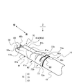
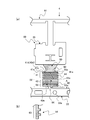
- FIG. 1 is an exploded perspective view of an electric wire with terminal fitting according to an embodiment of the present invention.
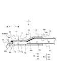
- FIG. 2 is an enlarged perspective view of the periphery of the wire connecting portion of the electric wire with terminal fittings shown in FIG. 3 is a cross-sectional view taken along line AA of the electric wire with terminal fittings shown in FIG.
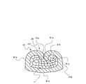
- FIG. 4 is a cross-sectional view taken along line BB of the electric wire with terminal fittings shown in FIG.
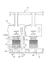
- FIG. 5 is a diagram showing a procedure for manufacturing an electric wire with terminal fittings.
- FIG. 6 is a diagram showing a procedure for manufacturing an electric wire with terminal fittings.
- FIG. 7 is a diagram showing a procedure for manufacturing an electric wire with terminal fittings.
- FIG. 8 is an enlarged perspective view of the periphery of the electric wire connecting portion of the electric wire with terminal fitting according to the first modification of the embodiment of the present invention.
- FIG. 9 is a view showing a state where a plate-like member that is a material of the terminal fitting shown in FIG.
- FIG. 10 is an enlarged perspective view of the periphery of the wire connecting portion of the electric wire with terminal fittings according to the second modification of the embodiment of the present invention.
- FIG. 11 is a view showing a state in which a plate-like member that is a material of the terminal fitting shown in FIG.
- FIG. 12A is a view showing a state in which a plate-like member that is a material of a terminal fitting of a terminal fitting-equipped electric wire according to a third modification of the embodiment of the present invention is punched, and FIG. It is the sectional view on the AA line of a).
- FIG. 13A is an enlarged perspective view of the vicinity of the wire connecting portion of the electric wire with terminal fittings according to Modification 4 of the embodiment of the present invention
- FIG. 13B is a cross-sectional view taken along the line AA in FIG.
- 14A is an enlarged perspective view of the periphery of the wire connecting portion of the electric wire with terminal fittings according to the modified example 5 of the embodiment of the present invention
- FIG. 14B is a cross-sectional view taken along the line AA in FIG. .
- FIG. 1 is an exploded perspective view of an electric wire 1 with terminal fittings according to an embodiment of the present invention.
- FIG. 2 is an enlarged perspective view of the periphery of the wire connecting portion 40 of the electric wire 1 with terminal fittings shown in FIG. 3 is a cross-sectional view taken along line AA of the electric wire 1 with terminal fittings shown in FIG. 4 is a cross-sectional view taken along line BB of the electric wire 1 with terminal fittings shown in FIG.
- the front-rear direction is defined as indicated by arrows in the figure for convenience of explanation.
- An electric wire with terminal fittings 1 includes an electric wire 10 including a conductor portion 11 and an insulating coating portion 12 surrounding the outer periphery of the conductor portion 11, and an electric wire connecting portion connected to an end portion 10 a of the electric wire 10. 40 and a terminal fitting 20 including 40.
- the conductor portion 11 is formed by bundling a plurality of strands 11a made of aluminum or aluminum alloy.
- the insulation coating portion 12 is made of an insulating synthetic resin, and is formed so as to surround the outer periphery of the conductor portion 11, thereby protecting the conductor portion 11 from the outside.
- the conductor part 11 illustrated what bundled the some strand 11a not only this but a single core wire may be sufficient.
- the terminal fitting 20 is a terminal fitting in which a plate-like member made of a metal such as copper or a copper alloy is formed by die pressing or the like.
- the terminal fitting 20 includes a mating terminal connecting portion 30 that is a connecting portion with a connecting mating terminal (not shown), an electric wire connecting portion 40 connected to the terminal portion 10a of the electric wire 10, and an mating terminal connecting portion 30 and an electric wire connecting portion. 40 and an intermediate portion 50 that is connected to 40.
- the mating terminal connecting portion 30 is configured such that a mating terminal (not shown) is brought into contact with an elastic contact piece provided in a cylinder of the connecting main body having a rectangular tube shape.
- the wire connection portion 40 has a cylindrical shape in which both end portions of the plate-like portion are combined, and an exposed conductor crimping portion 41 that is crimped to the exposed conductor portion 11 and an insulation coating crimp that is crimped to the insulating coating portion 12.
- the exposed conductor crimping portion 41 is provided on the front end side of the wire connecting portion 40 in the extending direction of the electric wire 10 and is exposed by removing the insulating coating portion 12 at the end of the terminal portion 10a of the electric wire 10.
- 11 is a portion to be crimped to 11.
- the front end side of the wire connection part 40 in the extending direction of the electric wire 10 is typically the front end side of the terminal part 10a of the electric wire 10, in other words, the front end of the conductor part 11 exposed from the insulating coating part 12. It corresponds to the part 11b side.
- the exposed conductor crimping part 41 is erected from a conductor crimping bottom wall part 41a on which the exposed conductor part 11 is placed, and both side edges of the conductor crimping bottom wall part 41a, and is a conductor extending from both sides of the conductor part 11 to the upper part. It has a pair of conductor crimping rising wall parts 41b crimped so as to surround the outer periphery of the part 11.
- the exposed conductor crimping portion 41 has an uneven surface portion 44 in which the inner surface 41c is formed in an uneven shape. More specifically, the concavo-convex surface portion 44 is a portion formed by continuously forming rhombus-shaped convex portions at a plurality of locations on the inner surface 41c.
- the uneven surface portion 44 has a function of increasing the adhesion strength by increasing the contact area between the exposed conductor crimping portion 41 and the conductor portion 11.
- the electric wire 1 with a terminal metal fitting of this Example illustrated what the uneven
- the insulating coating crimping portion 42 is a portion that is provided on the rear end side of the wire connecting portion 40 in the extending direction of the electric wire 10 and is crimped to the insulating coating portion 12.
- the rear end side of the wire connecting portion 40 in the extending direction of the electric wire 10 is typically the base end side opposite to the distal end side of the terminal portion 10a of the electric wire 10, in other words, the insulating coating portion 12.
- the insulating coating crimping portion 42 is erected from the insulating coating crimping bottom wall portion 42a on which the insulating coating portion 12 is placed, and both side edges of the insulating coating crimping bottom wall portion 42a. It has a pair of insulation coating crimping rising wall portions 42b that are crimped so as to surround the outer periphery of the insulation coating portion 12.
- the intermediate integral connecting portion 43 is a portion that integrally connects the exposed conductor crimping portion 41 and the insulating coating crimping portion 42 along the extending direction of the electric wire 10 so that the exposed conductor portion 11 is not exposed to the outside. It is. That is, the intermediate integral connecting portion 43 includes the exposed conductor crimping portion 41 and the insulating coating crimping portion 42 along the extending direction of the electric wire 10 so that the conductor portion 11 exposed from the insulating coating portion 12 is not exposed to the outside. It is the part which connects between.
- the intermediate integral connecting portion 43 is erected from an intermediate bottom wall portion 43 a on which the insulating coating portion 12 is placed and both side edges of the intermediate bottom wall portion 43 a, and the insulating coating portion 12 extends from both sides to the upper portion of the insulating coating portion 12. And a pair of intermediate upright wall portions 43b that are pressure-bonded so as to surround the outer periphery thereof.
- Such an intermediate integral connecting portion 43 connects the exposed conductor crimping portion 41 and the insulating coating crimping portion 42 so that each of the exposed conductor crimping portion 41 and the insulating coating crimping portion 42 is easily crimped to the electric wire 10. It has become. More specifically, in the intermediate integrated connecting portion 43, the difference between the outer diameter of the electric wire 10 in the portion covered with the insulating coating portion 12 and the outer diameter of the electric wire 10 in the exposed portion of the conductor portion 11 is reduced. As described above, the electric wire 10 is crimped so that the outer diameter of the electric wire 10 is gradually reduced from the insulating coating crimping portion 42 toward the exposed conductor crimping portion 41.
- Such a terminal fitting 20 includes the entire inner surface 50a of the intermediate portion 50, the front end portion 41d of the inner surface 41c of the exposed conductor crimping portion 41, the entire inner surface 43c of the intermediate integral connecting portion 43, and the insulating coating crimping portion.
- An insulating resin layer 60 is formed on the entire inner surface 42c of 42. That is, in the terminal fitting 20, an unformed portion of the insulating resin layer 60 is formed on a portion of the inner surface 40 a of the wire connecting portion 40 except for the front end portion 41 d. For this reason, after connecting the terminal fitting 20 to the electric wire 10, the terminal fitting 20 is heated at a temperature at which the insulating resin R is melted.
- the exposed conductor crimping portion 41 is electrically connected to the conductor portion 11 at the unformed portion 60, the front end opening 40b and the rear end opening 40c of the wire connecting portion 40 are sealed by the insulating resin R, so that the terminal fitting 20 It is possible to prevent water from entering the exposed conductor portion 11 from the outside.
- the tip end portion 11b of the exposed conductor portion 11 of the electric wire 10 is accommodated in the exposed conductor crimping portion 41, the exposed tip portion 11b of the conductor portion 11 is exposed to the exposed conductor crimping portion 41.
- the insulating resin layer 60 formed on the front end portion 41d of the inner surface 41c of the inner surface 41c is melted to be surely covered with the insulating resin R.
- insulating resin R a thermoplastic resin is used. Specifically, an insulating resin R such as polyethylene or polypropylene is exemplified, but the insulating resin R is not limited to this, and other insulating resins may be used.
- FIGS. 5 to 7 are diagrams showing a manufacturing procedure of the electric wire 1 with terminal fittings.
- the operator forms an insulating resin layer 60 by using a processing machine (not shown) so as to leave an unformed portion on the inner surface 41c of the exposed conductor crimping portion 41 among the inner surfaces of the terminal fitting 20. (See FIG. 5).
- an insulating resin layer 60 is formed on the plate-like member 21 before the plurality of terminal fittings 20 are die-cut.
- the insulating resin layer 60 is partially formed on the plate-like member 21, for example, the portion corresponding to the unformed portion of the insulating resin layer 60 is masked, and then the insulating resin R is applied. To do.
- An insulating resin layer 60 is formed over the entire inner surface 42c, and an unformed portion of the insulating resin layer 60 is formed in a portion of the inner surface 41c of the exposed conductor crimping portion 41 excluding the front end portion 41d. For this reason, the portion where the insulating resin layer 60 is formed and the portion where the insulating resin layer 60 is not formed can be formed in a straight line continuous in the horizontal direction of the plate-like member 21 in the drawing. .
- the insulating resin layer 60 is collectively formed on the plurality of terminal fittings 20. It has become so. Note that the insulating resin layer 60 may be formed after the plate-like member 21 is subjected to die cutting.
- the worker performs die cutting of the terminal fitting 20 on the plate-like member 21 using a processing machine (not shown) (see FIG. 6).
- a processing machine not shown
- a plurality of terminal fittings 20 in an unfolded state are formed.
- a band-shaped carrier 22 for connecting a plurality of terminal fittings 20 is formed, and a feeding claw for a processing machine (not shown) is inserted into a feed hole 22a formed in the carrier 22.
- the plate-like member 21 that has been die-cut by is conveyed to the next process.
- the operator performs a bending process on the unfolded terminal fitting 20 using a processing machine (not shown) to form a predetermined shape, and connects the wire connection portion 40 of the terminal fitting 20 to the electric wire 10 (see FIG. 7).
- a processing machine not shown
- the unformed portion of the insulating resin layer 60 of the exposed conductor crimping portion 41 is crimped to the conductor portion 11, and the terminal fitting 20 and the electric wire 10 are electrically connected.
- the operator heats the terminal fitting 20 at a temperature at which the insulating resin R is melted using a processing machine (not shown). Thereby, as shown in FIG. 3, the gap between the terminal fitting 20 and the electric wire 10 in the front end opening 40 b and the rear end opening 40 c of the electric wire connecting portion 40 is sealed with the insulating resin R.
- compression-bonding part 41 are match
- the intermediate integral connecting portion 43 is exposed between the exposed conductor crimping portion 41 and the insulating coating crimping portion 42 along the extending direction of the electric wire 10.
- an insulating resin layer 60 is formed at least on the front end portion 40d and the rear end portion 40e in the extending direction of the electric wire 10 on the inner surface 40a of the electric wire connecting portion 40.
- the insulating resin layer 60 formed on the front end portion 40d of the inner surface 40a of the electric wire connecting portion 40 in the extending direction of the electric wire 10 is melted.
- the exposed tip of the conductor 11 can be reliably covered.
- FIG. 8 is an enlarged perspective view of the periphery of the wire connecting portion 72 of the electric wire 2 with terminal fittings according to the first modification of the embodiment of the present invention.
- FIG. 9 is a view showing a state in which the plate-like member 71 that is a material of the terminal fitting 70 shown in FIG.
- the electric wire 2 with terminal metal fittings of this modification 1 is different from the electric wire 1 with terminal metal fittings of the embodiment in that a pair of crimping piece portions 73a and 73a are formed on the insulation coating crimping portion 73 of the terminal metal fitting 70.
- Other configurations are the same as those in the embodiment, and the same components as those in the embodiment are denoted by the same reference numerals.
- the terminal fitting 70 has a pair of crimping piece portions 73a and 73a formed in a piece shape by cutting both side end portions 73b and 73b of the insulating coating crimping portion 73 into a slit shape. Such a pair of pressure-bonding pieces 73a and 73a is easily bent and deformed.
- the electric wire 2 with terminal metal fittings of this modified example 1 can prevent water from entering the conductor portion 11 exposed from the outside of the terminal metal fitting 70 as in the case of the electric wire 1 with terminal metal fittings of the embodiment.
- the anticorrosion performance can be improved, and the pair of crimping pieces 73a and 73a formed on the insulating coating crimping portion 73 is easily bent and deformed.
- the insulating coating portion 12 is inserted into the slit-shaped cut, the adhesion strength between the insulating coating crimp portion 73 and the insulating coating portion 12 can be increased.
- FIG. 10 is an enlarged perspective view of the periphery of the wire connecting portion 82 of the electric wire 3 with terminal fittings according to the second modification of the embodiment of the present invention.
- FIG. 11 is a view showing a state where the plate-like member 81 that is the material of the terminal fitting shown in FIG.
- the electric wire 3 with terminal metal fittings of this modification 2 is different from the electric wire 1 with terminal metal fittings of the embodiment in that a through hole is formed in the insulation coating crimping portion 83 of the terminal metal fitting 80.
- Other configurations are the same as those in the embodiment, and the same components as those in the embodiment are denoted by the same reference numerals.
- the terminal fitting 80 is formed with through holes 83 a at two locations of the insulation coating crimping portion 83. More specifically, each through-hole 83a is arranged in the vicinity of the mating surface 83c with the mating surfaces 83c of the both side end portions 83b and 83b of the insulating coating crimping portion 83 in between.
- Such a terminal fitting 80 is securely crimped by the insulation coating portion 12 of the electric wire 10 because the insulation coating portion 12 is inserted into the through hole 83a when the insulation coating crimp portion 83 is crimped to the insulation coating portion 12.
- the electric wire 3 with a terminal metal fitting of this modification 2 can prevent water from entering the conductor portion 11 exposed from the outside of the terminal metal fitting 80 in the same manner as the electric wire 1 with a terminal metal fitting of the embodiment.
- the anticorrosion performance can be improved, and the terminal fitting 80 is more reliably crimped to the insulating coating portion 12.
- FIG. 12A is a view showing a state in which the plate-like member 91 that is a material of the terminal fitting 90 of the electric wire 4 with a terminal fitting according to the modified example 3 of the embodiment of the present invention is punched, and FIG. ) Is a cross-sectional view taken along line AA in FIG.
- the electric wire 4 with terminal metal fittings of this modification 3 is different from the electric wire 1 with terminal metal fittings of the embodiment in that an uneven surface portion 94 is formed on the insulation coating crimping portion 93 of the electric wire connecting portion 92 of the terminal metal fitting 90.
- Other configurations are the same as those in the embodiment, and the same components as those in the embodiment are denoted by the same reference numerals.
- the terminal fitting 90 has a concavo-convex surface portion 94 in which the inner surface 93a of the insulating coating crimp portion 93 is formed in a concavo-convex shape.
- the uneven surface portion 94 is formed by arranging convex portions protruding from the inner surface 93a in a rectangular cross section.
- Such a terminal fitting 90 is in close contact with the insulation coating crimping portion 93 and the insulation coating portion 12 by increasing the contact area between the insulation coating crimping portion 93 and the insulation coating portion 12 when the insulation coating crimping portion 93 is crimped to the insulation coating portion 12. It has a function to increase strength.
- the electric wire 4 with a terminal metal fitting of this modification 3 can prevent water from entering the conductor portion 11 exposed from the outside of the terminal metal fitting 90 as in the case of the electric wire 1 with a terminal metal fitting of the embodiment.
- the anticorrosion performance can be improved, and the contact area between the insulating coating crimping portion 93 and the insulating coating portion 12 is increased by the uneven surface portion 94, so that the adhesion strength between the insulating coating crimping portion 93 and the insulating coating portion 12 is increased. Can be increased.
- FIG. 13 (a) is an enlarged perspective view of the periphery of the wire connecting portion 110 of the electric wire 5 with terminal fittings according to Modification 4 of the embodiment of the present invention
- FIG. 13 (b) is a cross-sectional view taken along the line AA in FIG. It is.
- the electric wire 5 with terminal metal fittings of this modification 4 is the electric wire 1 with terminal metal fittings of the embodiment in that the electric wire connecting portion 110 of the terminal metal fitting 100 is formed in a cylindrical shape where both side end portions 110a and 110b of the plate-like portion overlap. And different.
- the wire connection part 110 includes an exposed conductor crimping part 111, an insulation coating crimping part 112, and an intermediate integral connecting part 113.
- Other configurations are the same as those in the embodiment, and the same components as those in the embodiment are denoted by the same reference numerals.
- the terminal fitting 100 is connected to the electric wire 10 so that the both end parts 110 a, 110 b of the plate-like portion overlap each other, and thus the both end parts 110 a. , 110b are more reliably closed, and water from the outside is more difficult to enter.
- the electric wire 5 with a terminal metal fitting of this modification 4 can prevent water from entering the conductor portion 11 exposed from the outside of the terminal metal fitting 100 as in the case of the electric wire 1 with a terminal metal fitting of the embodiment.
- the anti-corrosion performance can be improved, and the both end portions 110a and 110b of the wire connecting portion 110 are overlapped, so that water enters from the outside of the terminal fitting 100 via the mating surfaces 110c of the both end portions 110a and 110b. Since it becomes difficult, water can be prevented from entering the conductor portion 11 exposed from the outside of the terminal fitting 100.
- FIG. 14A is an enlarged perspective view of the periphery of the wire connecting portion 110 of the electric wire 6 with terminal fittings according to the modified example 5 of the embodiment of the present invention
- FIG. 14B is a cross-sectional view taken along the line AA in FIG. It is.
- the electric wire connecting portion 110 of the terminal metal fitting 100 is formed in a cylindrical shape in which both side end portions 110a and 110b of the plate-like portion are overlapped, and the exposed conductor crimping portion 111 is overlapped on both sides.
- the conductor part 11 consists of aluminum or an aluminum alloy, and the terminal metal fittings 20,70,80,90,100 exist.
- the present invention is not limited to this, and other metal materials may be used as the conductor portion 11 and the terminal fittings 20, 70, 80, 90, 100.
- copper or a copper alloy may be used as the conductor portion 11.
- the electric wires 1, 2, 3, 4, 5, 6 with terminal fittings are the front end portion 41d of the entire inner surface 50a of the intermediate portion 50 and the inner surface 41c of the exposed conductor crimping portion 41.
- An example in which the insulating resin layer 60 is formed on the entire inner surface 43c of the intermediate integral connecting portion 43 and the entire inner surface 42c of the insulating coating crimping portion 42 is not limited thereto.
- the layer 60 should just be formed in the front-end part and rear-end part in the extending direction of the electric wire 10 of the inner surface of the electric wire connection part 40,72,82,92,110.
- the insulating resin layer 60 is formed only at the front end portion and the rear end portion in the extending direction of the electric wire 10, at least both end openings of the electric wire connecting portions 40, 72, 82, 92, 110 are made of the insulating resin R. Sealed.
- the electric wires with terminal fittings 1, 2, 3, 4, 5 and 6 exemplify those in which the tip end portion 11b of the exposed conductor portion 11 is accommodated in the exposed conductor crimping portion.
- the present invention is not limited thereto, and the exposed tip portion 11b of the conductor portion 11 may be exposed from the front end opening of the wire connection portions 40, 72, 82, 92, and 110.
- the insulating resin R formed at the front end portions of the wire connecting portions 40, 72, 82, 92, 110 melts and spreads, thereby opening the front end openings of the wire connecting portions 40, 72, 82, 92, 110.
- the conductor part 11 exposed from can be covered with the insulating resin R.
- the insulating resin R can cover the tip portion 11 b of the conductor portion 11 that is more reliably exposed by forming the insulating resin layer 60 in the intermediate portion 50.
Landscapes
- Chemical & Material Sciences (AREA)
- Dispersion Chemistry (AREA)
- Connections Effected By Soldering, Adhesion, Or Permanent Deformation (AREA)
Abstract
Description
ところで、近年、自動車業界では環境への配慮から、車両を軽量化することによって燃費を向上させることが重要な課題となっている。このため、銅に比して軽量なアルミニウム、あるいはアルミニウム合金からなる導体部を用いた導体部と該導体部の外周を包囲する絶縁被覆部とを含む電線と、該電線の端末部に接続される電線接続部を含む端子金具と、を有してなる端子金具付き電線が注目されている。
しかしながら、アルミニウムは水および銅イオンの存在下では腐食し易いため、アルミニウム、あるいはアルミニウム合金からなる導体部と銅からなる端子金具との接続部分に水が侵入すると腐食し易いという問題があった。
そこで、導体部への水の付着を防ぐことによって導体部の腐蝕を防止するため、例えば特許文献1には、露出された導体部が配置される面に導体部の腐蝕を防止する防食剤が塗布されている端子金具付が記載さている。
図1は、本発明の実施例に係る端子金具付き電線1の分解斜視図である。図2は、図1に示した端子金具付き電線1の電線接続部40周辺の拡大斜視図である。図3は、図2に示した端子金具付き電線1のA-A線断面図である。図4は、図2に示した端子金具付き電線1のB-B線断面図である。
なお、本発明の実施例では説明の便宜上、図中矢印に示すように前後方向を定義する。
本発明の実施例に係る端子金具付き電線1は、導体部11と導体部11の外周を包囲する絶縁被覆部12とを含む電線10と、電線10の端末部10aに接続される電線接続部40を含む端子金具20と、を有してなる。
導体部11は、アルミニウム、あるいはアルミニウム合金からなる複数の素線11aが束ねられてなる。
絶縁被覆部12は、絶縁性の合成樹脂からなり、導体部11の外周を包囲するように形成されることによって、導体部11を外部から絶縁可能に保護するものである。
なお、導体部11は、複数の素線11aが束ねられてなるものを例示したが、これに限らず単芯線であっても構わない。
端子金具20は、銅、あるいは銅合金等の金属からなる板状部材が金型プレス加工等によって成形された端子金具である。この端子金具20は、不図示の接続相手端子との接続部分となる相手端子接続部30と、電線10の端末部10aに接続される電線接続部40と、相手端子接続部30と電線接続部40とを連結する中間部50とを有してなる。
この露出導体圧着部41は、露出された導体部11が載置される導体圧着底壁部41aと、導体圧着底壁部41aの両側縁から起立され、導体部11の両側部から上部にわたって導体部11の外周を包囲するように圧着される一対の導体圧着起立壁部41bとを有してなる。
また、露出導体圧着部41は、内側の面41cが凹凸形状に形成されてなる凹凸表面部44を有してなる。より具体的には、凹凸表面部44は、内側の面41cの複数箇所にひし形形状の凸部が連続して形成されてなる部分である。この凹凸表面部44は、露出導体圧着部41と導体部11との接触面積が増大されることによって密着強度を高める機能を有してなる。
なお、この実施例の端子金具付き電線1は、凹凸表面部44が内側の面41cの複数箇所にひし形形状の凸部が連続して形成されてなるものを例示したが、これに限らず、露出導体圧着部41の内側の面41cが凹凸形状に形成されるようになっていればその他の形状であっても構わない。
この絶縁被覆圧着部42は、絶縁被覆部12が載置される絶縁被覆圧着底壁部42aと、絶縁被覆圧着底壁部42aの両側縁から起立され、絶縁被覆部12の両側部から上部にわたって絶縁被覆部12の外周を包囲するように圧着される一対の絶縁被覆圧着起立壁部42bとを有してなる。
この中間一体連接部43は、絶縁被覆部12が載置される中間底壁部43aと、中間底壁部43aの両側縁から起立され、絶縁被覆部12の両側部から上部にわたって絶縁被覆部12の外周を包囲するように圧着される一対の中間起立壁部43bとを有してなる。
より具体的には、中間一体連接部43は、絶縁被覆部12に覆われた部分の電線10の外径と、露出された導体部11の部分の電線10の外径との差が小さくなるように、絶縁被覆圧着部42から露出導体圧着部41に向けて電線10の外径が漸次縮径されるように電線10に圧着されるようになっている。
このため、端子金具20を電線10に接続させた後に、端子金具20を絶縁樹脂Rが溶融される温度で加熱することによって、図3に示すように、露出導体圧着部41の絶縁樹脂の層60の未形成部分で露出導体圧着部41が導体部11に電気的に接続されつつ、電線接続部40の前端開口40bおよび後端開口40cが絶縁樹脂Rによって封止されるので、端子金具20の外部から、露出された導体部11に水が侵入されることを防ぐことができる。
まず、作業者は、不図示の加工機を用いて端子金具20の内側の面のうち、露出導体圧着部41の内側の面41cに未形成部分を残すようにして絶縁樹脂の層60を形成する(図5参照)。
この樹脂層形成工程では、複数の端子金具20が型抜き処理される前の板状部材21に対して、絶縁樹脂の層60が形成される。ここで、板状部材21に対して絶縁樹脂の層60を部分的に形成する場合、例えば、絶縁樹脂の層60の未形成部分に対応する部分にマスキングを施し、その後に絶縁樹脂Rを塗布するようにする。
このため、絶縁樹脂の層60が形成される部分、および絶縁樹脂の層60の未形成部分を板状部材21の図中横方向に連続する直線状に形成することができるようになっている。
このように、複数の端子金具20が型抜きされる前の板状部材21に絶縁樹脂の層60を形成することによって、複数の端子金具20に対して一括で絶縁樹脂の層60が形成されるようになっている。
なお、絶縁樹脂の層60は、板状部材21に対して型抜き加工を行なった後に形成するようにしても構わない。
次に、図8および図9を用いて本発明の実施例に係る端子金具付き電線1の変形例1について説明する。図8は、本発明の実施例の変形例1の端子金具付き電線2の電線接続部72周辺の拡大斜視図である。図9は、図8に示した端子金具70の材料となる板状部材71が型抜きされた状態を示した図である。
この変形例1の端子金具付き電線2は、端子金具70の絶縁被覆圧着部73に一対の圧着片部73a,73aが形成されてなる点で実施例の端子金具付き電線1と異なる。
なお、その他の構成は実施例と同様であり、実施例と同一構成部分には同一符号を付している。
次に、図10および図11を用いて本発明の実施例に係る端子金具付き電線1の変形例2について説明する。図10は、本発明の実施例の変形例2の端子金具付き電線3の電線接続部82周辺の拡大斜視図である。図11は、図10に示した端子金具の材料となる板状部材81が型抜きされた状態を示した図である。
この変形例2の端子金具付き電線3は、端子金具80の絶縁被覆圧着部83に貫通孔が形成されてなる点で実施例の端子金具付き電線1と異なる。
なお、その他の構成は実施例と同様であり、実施例と同一構成部分には同一符号を付している。
このような端子金具80は、絶縁被覆圧着部83が絶縁被覆部12に圧着された場合、絶縁被覆部12が貫通孔83a内にくい込まれるため、電線10の絶縁被覆部12により確実に圧着される。
なお、この変形例2の端子金具付き電線3は、絶縁被覆圧着部83の二箇所に貫通孔83aが形成されてなるものを例示したが、これに限らず、絶縁被覆圧着部83の少なくとも一箇所に貫通孔83aが形成されていればよい。
次に、図12を用いて本発明の実施例に係る端子金具付き電線1の変形例3について説明する。図12は、(a)が本発明の実施例の変形例3の端子金具付き電線4の端子金具90の材料となる板状部材91が型抜きされた状態を示した図であり、(b)が(a)のA-A線断面図である。
この変形例3の端子金具付き電線4は、端子金具90の電線接続部92の絶縁被覆圧着部93に凹凸表面部94が形成されてなる点で実施例の端子金具付き電線1と異なる。
なお、その他の構成は実施例と同様であり、実施例と同一構成部分には同一符号を付している。
この凹凸表面部94は、断面矩形状に内側の面93aから突出された凸部が並んで設けられてなる。このような端子金具90は、絶縁被覆圧着部93が絶縁被覆部12に圧着された場合、凹凸表面部94によって絶縁被覆圧着部93と絶縁被覆部12との接触面積が増大されることによって密着強度を高める機能を有してなる。
なお、この変形例3の端子金具付き電線4は、凹凸表面部94が断面矩形状に内側の面93aから突出された凸部が並んで設けられてなるものを例示したが、これに限らず、絶縁被覆圧着部93の内側の面93aが凹凸形状に形成されるようになっていればその他の形状であっても構わない。
次に、図13を用いて本発明の実施例に係る端子金具付き電線1の変形例4について説明する。図13は、(a)が本発明の実施例の変形例4の端子金具付き電線5の電線接続部110周辺の拡大斜視図であり、(b)が(a)のA-A線断面図である。
この変形例4の端子金具付き電線5は、端子金具100の電線接続部110が板状部分の両側端部110a,110bが重なり合う筒状に形成されてなる点で実施例の端子金具付き電線1と異なる。電線接続部110は、露出導体圧着部111と、絶縁被覆圧着部112と、中間一体連接部113と、を有してなる。
なお、その他の構成は実施例と同様であり、実施例と同一構成部分には同一符号を付している。
次に、図14を用いて本発明の実施例に係る端子金具付き電線1の変形例5について説明する。図14は、(a)が本発明の実施例の変形例5の端子金具付き電線6の電線接続部110周辺の拡大斜視図であり、(b)が(a)のA-A線断面図である。
この変形例5の端子金具付き電線6は、端子金具100の電線接続部110が板状部分の両側端部110a,110bが重なり合う筒状に形成されてなり、かつ露出導体圧着部111が重なり合う両側端部110a,110bのうち外側の側端部110bの内側の面に絶縁樹脂の層60が形成されてなる点で実施例の端子金具付き電線1と異なる。
なお、その他の構成は実施例と同様であり、実施例と同一構成部分には同一符号を付している。
10 電線
10a 端末部
11 導体部
11a 素線
11b 先端部
12 絶縁被覆部
20,70,80,90,100 端子金具
21,71,81,91 板状部材
22 キャリア
22a 送り孔
30 相手端子接続部
40,72,82,92,110 電線接続部
40a,41c,42c,43c,50a,93a 内側の面
40b 前端開口
40c 後端開口
40d,41d 前端部
40e 後端部
41,111 露出導体圧着部
41a 導体圧着底壁部
41b 導体圧着起立壁部
41e,73b,83b,110a,110b 側端部
41f,83c,110c 合わせ面
42,73,83,93,112 絶縁被覆圧着部
42a 絶縁被覆圧着底壁部
42b 絶縁被覆圧着起立壁部
43,113 中間一体連接部
43a 中間底壁部
43b 中間起立壁部
44,94 凹凸表面部
50 中間部
60 絶縁樹脂の層
73a 圧着片部
83a 貫通孔
Claims (8)
- 導体部と該導体部の外周を包囲する絶縁被覆部とを含む電線と、
該電線の端末部に接続される電線接続部を含む端子金具と、
を有し、
前記電線接続部は、
前記電線の延在方向における前端側に設けられ、かつ前記端末部の先端の前記絶縁被覆部が除去されることによって露出された前記導体部に圧着される露出導体圧着部と、
前記電線の延在方向における後端側に設けられ、かつ前記絶縁被覆部に圧着される絶縁被覆圧着部と、
前記電線の延在方向に沿って前記露出導体圧着部と前記絶縁被覆圧着部との間を前記露出された導体部が外部に露出されないように一体的に連接する中間一体連接部と、
を有してなり、
前記電線接続部の内側の面の、少なくとも前記電線の延在方向における前端部および後端部に絶縁樹脂の層が形成され、かつ前記電線接続部の内側の面の、前記導体部に圧着される部分の少なくとも一部に前記絶縁樹脂の層の未形成部分が形成されてなることを特徴とする端子金具付き電線。 - 前記電線は、
前記露出された導体部の先端部が前記露出導体圧着部内に収容されてなることを特徴とする請求項1に記載の端子金具付き電線。 - 前記電線接続部は、
板状部分の両側端部が合わせられた筒状をなし、
前記絶縁被覆圧着部は、
前記両側端部がスリット状に切り込まれることによって片状に形成されてなる一対の圧着片部、
を有してなることを特徴とする請求項1または2に記載の端子金具付き電線。 - 前記絶縁被覆圧着部は、
少なくとも一箇所に貫通孔が形成されてなることを特徴とする請求項1、2または3に記載の端子金具付き電線。 - 前記露出導体圧着部、および前記絶縁被覆圧着部は、
前記内側の面が凹凸形状に形成されてなる凹凸表面部、
を有してなることを特徴とする請求項1、2、3または4に記載の端子金具付き電線。 - 前記電線接続部は、
板状部分の両側端部が重なり合う筒状に形成されてなることを特徴とする請求項1、2、3、4または5に記載の端子金具付き電線。 - 前記露出導体圧着部は、
前記重なり合う両側端部のうち外側の側端部の内側の面に前記絶縁樹脂の層が形成されてなることを特徴とする請求項6に記載の端子金具付き電線。 - 前記導体部は、
アルミニウム、あるいはアルミニウム合金からなり、
前記端子金具は、
銅、あるいは銅合金からなることを特徴とする請求項1、2、3、4、5、6、または7に記載の端子金具付き電線。
Priority Applications (3)
| Application Number | Priority Date | Filing Date | Title |
|---|---|---|---|
| DE112014000921.0T DE112014000921T5 (de) | 2013-02-20 | 2014-01-23 | Elektrodraht mit Metallanschlussstück |
| CN201480009468.5A CN105075019B (zh) | 2013-02-20 | 2014-01-23 | 带端子金属件的电线 |
| US14/828,674 US10096913B2 (en) | 2013-02-20 | 2015-08-18 | Electric wire with terminal metal fitting |
Applications Claiming Priority (2)
| Application Number | Priority Date | Filing Date | Title |
|---|---|---|---|
| JP2013030764A JP6192947B2 (ja) | 2013-02-20 | 2013-02-20 | 端子金具付き電線 |
| JP2013-030764 | 2013-02-20 |
Related Child Applications (1)
| Application Number | Title | Priority Date | Filing Date |
|---|---|---|---|
| US14/828,674 Continuation US10096913B2 (en) | 2013-02-20 | 2015-08-18 | Electric wire with terminal metal fitting |
Publications (1)
| Publication Number | Publication Date |
|---|---|
| WO2014129262A1 true WO2014129262A1 (ja) | 2014-08-28 |
Family
ID=51391058
Family Applications (1)
| Application Number | Title | Priority Date | Filing Date |
|---|---|---|---|
| PCT/JP2014/051396 Ceased WO2014129262A1 (ja) | 2013-02-20 | 2014-01-23 | 端子金具付き電線 |
Country Status (5)
| Country | Link |
|---|---|
| US (1) | US10096913B2 (ja) |
| JP (1) | JP6192947B2 (ja) |
| CN (1) | CN105075019B (ja) |
| DE (1) | DE112014000921T5 (ja) |
| WO (1) | WO2014129262A1 (ja) |
Cited By (2)
| Publication number | Priority date | Publication date | Assignee | Title |
|---|---|---|---|---|
| JP2016081611A (ja) * | 2014-10-10 | 2016-05-16 | 矢崎総業株式会社 | 圧着端子と電線の接続構造 |
| DE102016225122B4 (de) | 2015-12-16 | 2023-04-13 | Yazaki Corporation | Quetschverbindung |
Families Citing this family (21)
| Publication number | Priority date | Publication date | Assignee | Title |
|---|---|---|---|---|
| JP6426907B2 (ja) * | 2014-04-04 | 2018-11-21 | 矢崎総業株式会社 | 圧着端子と電線の接続構造 |
| JP6063435B2 (ja) * | 2014-12-15 | 2017-01-18 | 矢崎総業株式会社 | シート貼付方法及びシート貼付装置 |
| DE102015209855A1 (de) * | 2015-05-28 | 2016-12-01 | Te Connectivity Germany Gmbh | Elektrisches Kontaktierungselement mit einer feinstrukturierten Kontaktierungsfläche |
| JP6254567B2 (ja) | 2015-12-16 | 2017-12-27 | 矢崎総業株式会社 | 圧着端子及び端子圧着装置 |
| JP6307059B2 (ja) | 2015-12-16 | 2018-04-04 | 矢崎総業株式会社 | 圧着端子 |
| JP6326035B2 (ja) | 2015-12-16 | 2018-05-16 | 矢崎総業株式会社 | 圧着端子 |
| JP6423783B2 (ja) | 2015-12-16 | 2018-11-14 | 矢崎総業株式会社 | 圧着端子 |
| JP6367785B2 (ja) | 2015-12-16 | 2018-08-01 | 矢崎総業株式会社 | 端子付き電線及び端子圧着装置 |
| JP6422851B2 (ja) | 2015-12-16 | 2018-11-14 | 矢崎総業株式会社 | 圧着端子の製造方法 |
| JP2018078022A (ja) * | 2016-11-09 | 2018-05-17 | 矢崎総業株式会社 | コネクタ |
| JP6886814B2 (ja) * | 2016-12-27 | 2021-06-16 | 矢崎総業株式会社 | 圧着端子 |
| JP6874555B2 (ja) * | 2017-06-16 | 2021-05-19 | 株式会社オートネットワーク技術研究所 | バスバーおよび当該バスバーを備えた配線モジュール |
| JP6546626B2 (ja) * | 2017-07-11 | 2019-07-17 | 矢崎総業株式会社 | 端子付き電線、端子圧着装置及び端子付き電線の製造方法 |
| JP2019029128A (ja) * | 2017-07-27 | 2019-02-21 | 矢崎総業株式会社 | 端子付き電線 |
| JP6904147B2 (ja) * | 2017-08-01 | 2021-07-14 | 株式会社オートネットワーク技術研究所 | 端子付き電線 |
| WO2019215949A1 (ja) * | 2018-05-10 | 2019-11-14 | 株式会社オートネットワーク技術研究所 | 端子付き電線 |
| JP6820294B2 (ja) * | 2018-07-09 | 2021-01-27 | 矢崎総業株式会社 | 端子付き電線 |
| JP6803877B2 (ja) * | 2018-07-09 | 2020-12-23 | 矢崎総業株式会社 | 端子付き電線 |
| JP7065061B2 (ja) * | 2019-08-29 | 2022-05-11 | 矢崎総業株式会社 | 電線付き端子及びその製造方法 |
| JP7225166B2 (ja) * | 2020-07-22 | 2023-02-20 | 矢崎総業株式会社 | 電線の製造方法および電線製造装置 |
| US11264735B1 (en) * | 2020-08-28 | 2022-03-01 | TE Connectivity Services Gmbh | Electrical terminal for terminating a wide size range of magnet wires |
Citations (6)
| Publication number | Priority date | Publication date | Assignee | Title |
|---|---|---|---|---|
| JPH03104955U (ja) * | 1990-02-15 | 1991-10-30 | ||
| WO2011096526A1 (ja) * | 2010-02-05 | 2011-08-11 | 古河電気工業株式会社 | 圧着端子、接続構造体、並びに圧着端子の作製方法 |
| WO2011122622A1 (ja) * | 2010-03-30 | 2011-10-06 | 古河電気工業株式会社 | 圧着端子、接続構造体及びコネクタ |
| JP2011243329A (ja) * | 2010-05-14 | 2011-12-01 | Yazaki Corp | 圧着端子の電線に対する接続構造 |
| JP2012069449A (ja) * | 2010-09-27 | 2012-04-05 | Furukawa Electric Co Ltd:The | 圧着端子、接続構造体及びコネクタ |
| JP2012155892A (ja) * | 2011-01-24 | 2012-08-16 | Auto Network Gijutsu Kenkyusho:Kk | 圧着端子及び端子付電線 |
Family Cites Families (13)
| Publication number | Priority date | Publication date | Assignee | Title |
|---|---|---|---|---|
| US5422438A (en) * | 1991-02-07 | 1995-06-06 | Raychem Sa | Electrical crimp connector |
| JP3110494B2 (ja) * | 1991-06-14 | 2000-11-20 | バーグ・テクノロジー・インコーポレーテッド | コネクタ |
| US5532433A (en) * | 1991-11-13 | 1996-07-02 | Yazaki Corporation | Waterproof-type terminal connection structure and method of producing same |
| JPH0736364U (ja) | 1993-12-10 | 1995-07-04 | 住友電装株式会社 | 高圧抵抗電線用の端子 |
| JP2923520B2 (ja) * | 1994-06-30 | 1999-07-26 | 矢崎総業株式会社 | コネクタ |
| JPH09115564A (ja) * | 1995-10-20 | 1997-05-02 | Yazaki Corp | 高圧電線用接続端子 |
| JP2002184479A (ja) * | 2000-12-18 | 2002-06-28 | Jst Mfg Co Ltd | 雌圧着端子 |
| JP5147648B2 (ja) | 2008-11-07 | 2013-02-20 | 矢崎総業株式会社 | 圧着端子及び圧着端子における電線固定構造 |
| JP5241529B2 (ja) * | 2009-01-14 | 2013-07-17 | 株式会社オートネットワーク技術研究所 | 連鎖端子、端子金具、及び端子金具の製造方法 |
| JP5539009B2 (ja) | 2010-05-14 | 2014-07-02 | 矢崎総業株式会社 | 圧着端子の電線に対する接続構造 |
| JP5601233B2 (ja) * | 2011-02-07 | 2014-10-08 | 住友電装株式会社 | 端子金具 |
| JP2013008610A (ja) | 2011-06-27 | 2013-01-10 | Auto Network Gijutsu Kenkyusho:Kk | 端子付電線 |
| JP5953591B2 (ja) | 2012-04-05 | 2016-07-20 | 矢崎総業株式会社 | 圧着端子を電線に圧着する方法 |
-
2013
- 2013-02-20 JP JP2013030764A patent/JP6192947B2/ja active Active
-
2014
- 2014-01-23 WO PCT/JP2014/051396 patent/WO2014129262A1/ja not_active Ceased
- 2014-01-23 DE DE112014000921.0T patent/DE112014000921T5/de not_active Ceased
- 2014-01-23 CN CN201480009468.5A patent/CN105075019B/zh active Active
-
2015
- 2015-08-18 US US14/828,674 patent/US10096913B2/en active Active
Patent Citations (6)
| Publication number | Priority date | Publication date | Assignee | Title |
|---|---|---|---|---|
| JPH03104955U (ja) * | 1990-02-15 | 1991-10-30 | ||
| WO2011096526A1 (ja) * | 2010-02-05 | 2011-08-11 | 古河電気工業株式会社 | 圧着端子、接続構造体、並びに圧着端子の作製方法 |
| WO2011122622A1 (ja) * | 2010-03-30 | 2011-10-06 | 古河電気工業株式会社 | 圧着端子、接続構造体及びコネクタ |
| JP2011243329A (ja) * | 2010-05-14 | 2011-12-01 | Yazaki Corp | 圧着端子の電線に対する接続構造 |
| JP2012069449A (ja) * | 2010-09-27 | 2012-04-05 | Furukawa Electric Co Ltd:The | 圧着端子、接続構造体及びコネクタ |
| JP2012155892A (ja) * | 2011-01-24 | 2012-08-16 | Auto Network Gijutsu Kenkyusho:Kk | 圧着端子及び端子付電線 |
Cited By (2)
| Publication number | Priority date | Publication date | Assignee | Title |
|---|---|---|---|---|
| JP2016081611A (ja) * | 2014-10-10 | 2016-05-16 | 矢崎総業株式会社 | 圧着端子と電線の接続構造 |
| DE102016225122B4 (de) | 2015-12-16 | 2023-04-13 | Yazaki Corporation | Quetschverbindung |
Also Published As
| Publication number | Publication date |
|---|---|
| CN105075019B (zh) | 2017-05-31 |
| US10096913B2 (en) | 2018-10-09 |
| CN105075019A (zh) | 2015-11-18 |
| JP6192947B2 (ja) | 2017-09-06 |
| US20150357722A1 (en) | 2015-12-10 |
| DE112014000921T5 (de) | 2015-11-05 |
| JP2014160591A (ja) | 2014-09-04 |
Similar Documents
| Publication | Publication Date | Title |
|---|---|---|
| JP6192947B2 (ja) | 端子金具付き電線 | |
| US9444154B2 (en) | Terminal fitting-equipped conductor | |
| US9379460B2 (en) | Terminal welded and crimped to a wire and a shrinkable tube covering the wire and the terminal | |
| JP6438670B2 (ja) | 圧着端子と電線の接続構造 | |
| JP6048859B2 (ja) | 導電線、導電線の製造方法及び導電線の配索構造 | |
| US9112287B2 (en) | Swaging connection structure | |
| JP6582649B2 (ja) | シールド構造 | |
| CN106165200A (zh) | 电线连接用的端子及该端子的电线连接结构 | |
| US9147944B2 (en) | Terminal fitting | |
| CN104040792B (zh) | 压接端子、连接结构体、线束以及连接器 | |
| CN104584329A (zh) | 装接有压接端子的铝电线 | |
| JP2018037374A (ja) | 端子付き電線 | |
| US20170129423A1 (en) | Shielded conductive path | |
| JP2014038836A (ja) | 圧着端子、接続構造体、コネクタ、及び圧着端子の圧着方法 | |
| US10224647B2 (en) | Wire with a crimped terminal | |
| JP6062212B2 (ja) | 端子付き電線、及び端子付き電線の製造方法 | |
| CN109149165B (zh) | 带端子的电线以及线束 | |
| CN108075242B (zh) | 电线的接合结构以及电线束 | |
| JP6709705B2 (ja) | 端子付き電線 | |
| JP2016054037A (ja) | 被覆電線の接合方法 | |
| JP2016201330A (ja) | ワイヤーハーネス及びシート状電線部材 | |
| JP6107692B2 (ja) | 電磁シールド部材およびワイヤハーネス | |
| JP2018092739A (ja) | 端子付き電線、端子、端子付き電線の製造方法、ワイヤハーネス | |
| JP6276820B2 (ja) | 被覆電線の接合方法 | |
| JP6310441B2 (ja) | 圧着端子、電線接続構造体、及びワイヤハーネス |
Legal Events
| Date | Code | Title | Description |
|---|---|---|---|
| WWE | Wipo information: entry into national phase |
Ref document number: 201480009468.5 Country of ref document: CN |
|
| 121 | Ep: the epo has been informed by wipo that ep was designated in this application |
Ref document number: 14754644 Country of ref document: EP Kind code of ref document: A1 |
|
| WWE | Wipo information: entry into national phase |
Ref document number: 112014000921 Country of ref document: DE Ref document number: 1120140009210 Country of ref document: DE |
|
| 122 | Ep: pct application non-entry in european phase |
Ref document number: 14754644 Country of ref document: EP Kind code of ref document: A1 |