US9147944B2 - Terminal fitting - Google Patents
Terminal fitting Download PDFInfo
- Publication number
- US9147944B2 US9147944B2 US14/373,189 US201214373189A US9147944B2 US 9147944 B2 US9147944 B2 US 9147944B2 US 201214373189 A US201214373189 A US 201214373189A US 9147944 B2 US9147944 B2 US 9147944B2
- Authority
- US
- United States
- Prior art keywords
- core
- thinning
- crimping
- crimped
- terminal fitting
- Prior art date
- Legal status (The legal status is an assumption and is not a legal conclusion. Google has not performed a legal analysis and makes no representation as to the accuracy of the status listed.)
- Expired - Fee Related
Links
- 238000002788 crimping Methods 0.000 claims abstract description 51
- 239000000463 material Substances 0.000 description 21
- 229920005989 resin Polymers 0.000 description 19
- 239000011347 resin Substances 0.000 description 19
- 229910052782 aluminium Inorganic materials 0.000 description 10
- XAGFODPZIPBFFR-UHFFFAOYSA-N aluminium Chemical compound [Al] XAGFODPZIPBFFR-UHFFFAOYSA-N 0.000 description 10
- 238000009413 insulation Methods 0.000 description 10
- 238000004078 waterproofing Methods 0.000 description 9
- 238000005452 bending Methods 0.000 description 8
- 239000011248 coating agent Substances 0.000 description 6
- 238000000576 coating method Methods 0.000 description 6
- 229910052751 metal Inorganic materials 0.000 description 4
- 239000002184 metal Substances 0.000 description 4
- 230000000694 effects Effects 0.000 description 3
- 229910000881 Cu alloy Inorganic materials 0.000 description 2
- 230000013011 mating Effects 0.000 description 2
- 229910000838 Al alloy Inorganic materials 0.000 description 1
- RYGMFSIKBFXOCR-UHFFFAOYSA-N Copper Chemical compound [Cu] RYGMFSIKBFXOCR-UHFFFAOYSA-N 0.000 description 1
- 239000012141 concentrate Substances 0.000 description 1
- 238000005260 corrosion Methods 0.000 description 1
- 230000007797 corrosion Effects 0.000 description 1
- 238000010438 heat treatment Methods 0.000 description 1
- 238000004519 manufacturing process Methods 0.000 description 1
- 150000002739 metals Chemical class 0.000 description 1
- 238000000034 method Methods 0.000 description 1
- 238000007789 sealing Methods 0.000 description 1
- 229920003002 synthetic resin Polymers 0.000 description 1
- 239000000057 synthetic resin Substances 0.000 description 1
- XLYOFNOQVPJJNP-UHFFFAOYSA-N water Substances O XLYOFNOQVPJJNP-UHFFFAOYSA-N 0.000 description 1
- 239000013585 weight reducing agent Substances 0.000 description 1
Images


Classifications
-
- H—ELECTRICITY
- H01—ELECTRIC ELEMENTS
- H01R—ELECTRICALLY-CONDUCTIVE CONNECTIONS; STRUCTURAL ASSOCIATIONS OF A PLURALITY OF MUTUALLY-INSULATED ELECTRICAL CONNECTING ELEMENTS; COUPLING DEVICES; CURRENT COLLECTORS
- H01R4/00—Electrically-conductive connections between two or more conductive members in direct contact, i.e. touching one another; Means for effecting or maintaining such contact; Electrically-conductive connections having two or more spaced connecting locations for conductors and using contact members penetrating insulation
- H01R4/10—Electrically-conductive connections between two or more conductive members in direct contact, i.e. touching one another; Means for effecting or maintaining such contact; Electrically-conductive connections having two or more spaced connecting locations for conductors and using contact members penetrating insulation effected solely by twisting, wrapping, bending, crimping, or other permanent deformation
- H01R4/18—Electrically-conductive connections between two or more conductive members in direct contact, i.e. touching one another; Means for effecting or maintaining such contact; Electrically-conductive connections having two or more spaced connecting locations for conductors and using contact members penetrating insulation effected solely by twisting, wrapping, bending, crimping, or other permanent deformation by crimping
- H01R4/183—Electrically-conductive connections between two or more conductive members in direct contact, i.e. touching one another; Means for effecting or maintaining such contact; Electrically-conductive connections having two or more spaced connecting locations for conductors and using contact members penetrating insulation effected solely by twisting, wrapping, bending, crimping, or other permanent deformation by crimping for cylindrical elongated bodies, e.g. cables having circular cross-section
- H01R4/184—Electrically-conductive connections between two or more conductive members in direct contact, i.e. touching one another; Means for effecting or maintaining such contact; Electrically-conductive connections having two or more spaced connecting locations for conductors and using contact members penetrating insulation effected solely by twisting, wrapping, bending, crimping, or other permanent deformation by crimping for cylindrical elongated bodies, e.g. cables having circular cross-section comprising a U-shaped wire-receiving portion
- H01R4/185—Electrically-conductive connections between two or more conductive members in direct contact, i.e. touching one another; Means for effecting or maintaining such contact; Electrically-conductive connections having two or more spaced connecting locations for conductors and using contact members penetrating insulation effected solely by twisting, wrapping, bending, crimping, or other permanent deformation by crimping for cylindrical elongated bodies, e.g. cables having circular cross-section comprising a U-shaped wire-receiving portion combined with a U-shaped insulation-receiving portion
-
- H—ELECTRICITY
- H01—ELECTRIC ELEMENTS
- H01R—ELECTRICALLY-CONDUCTIVE CONNECTIONS; STRUCTURAL ASSOCIATIONS OF A PLURALITY OF MUTUALLY-INSULATED ELECTRICAL CONNECTING ELEMENTS; COUPLING DEVICES; CURRENT COLLECTORS
- H01R4/00—Electrically-conductive connections between two or more conductive members in direct contact, i.e. touching one another; Means for effecting or maintaining such contact; Electrically-conductive connections having two or more spaced connecting locations for conductors and using contact members penetrating insulation
- H01R4/10—Electrically-conductive connections between two or more conductive members in direct contact, i.e. touching one another; Means for effecting or maintaining such contact; Electrically-conductive connections having two or more spaced connecting locations for conductors and using contact members penetrating insulation effected solely by twisting, wrapping, bending, crimping, or other permanent deformation
- H01R4/18—Electrically-conductive connections between two or more conductive members in direct contact, i.e. touching one another; Means for effecting or maintaining such contact; Electrically-conductive connections having two or more spaced connecting locations for conductors and using contact members penetrating insulation effected solely by twisting, wrapping, bending, crimping, or other permanent deformation by crimping
- H01R4/183—Electrically-conductive connections between two or more conductive members in direct contact, i.e. touching one another; Means for effecting or maintaining such contact; Electrically-conductive connections having two or more spaced connecting locations for conductors and using contact members penetrating insulation effected solely by twisting, wrapping, bending, crimping, or other permanent deformation by crimping for cylindrical elongated bodies, e.g. cables having circular cross-section
- H01R4/184—Electrically-conductive connections between two or more conductive members in direct contact, i.e. touching one another; Means for effecting or maintaining such contact; Electrically-conductive connections having two or more spaced connecting locations for conductors and using contact members penetrating insulation effected solely by twisting, wrapping, bending, crimping, or other permanent deformation by crimping for cylindrical elongated bodies, e.g. cables having circular cross-section comprising a U-shaped wire-receiving portion
-
- H—ELECTRICITY
- H01—ELECTRIC ELEMENTS
- H01R—ELECTRICALLY-CONDUCTIVE CONNECTIONS; STRUCTURAL ASSOCIATIONS OF A PLURALITY OF MUTUALLY-INSULATED ELECTRICAL CONNECTING ELEMENTS; COUPLING DEVICES; CURRENT COLLECTORS
- H01R4/00—Electrically-conductive connections between two or more conductive members in direct contact, i.e. touching one another; Means for effecting or maintaining such contact; Electrically-conductive connections having two or more spaced connecting locations for conductors and using contact members penetrating insulation
- H01R4/10—Electrically-conductive connections between two or more conductive members in direct contact, i.e. touching one another; Means for effecting or maintaining such contact; Electrically-conductive connections having two or more spaced connecting locations for conductors and using contact members penetrating insulation effected solely by twisting, wrapping, bending, crimping, or other permanent deformation
- H01R4/18—Electrically-conductive connections between two or more conductive members in direct contact, i.e. touching one another; Means for effecting or maintaining such contact; Electrically-conductive connections having two or more spaced connecting locations for conductors and using contact members penetrating insulation effected solely by twisting, wrapping, bending, crimping, or other permanent deformation by crimping
- H01R4/188—Electrically-conductive connections between two or more conductive members in direct contact, i.e. touching one another; Means for effecting or maintaining such contact; Electrically-conductive connections having two or more spaced connecting locations for conductors and using contact members penetrating insulation effected solely by twisting, wrapping, bending, crimping, or other permanent deformation by crimping having an uneven wire-receiving surface to improve the contact
-
- H—ELECTRICITY
- H01—ELECTRIC ELEMENTS
- H01R—ELECTRICALLY-CONDUCTIVE CONNECTIONS; STRUCTURAL ASSOCIATIONS OF A PLURALITY OF MUTUALLY-INSULATED ELECTRICAL CONNECTING ELEMENTS; COUPLING DEVICES; CURRENT COLLECTORS
- H01R4/00—Electrically-conductive connections between two or more conductive members in direct contact, i.e. touching one another; Means for effecting or maintaining such contact; Electrically-conductive connections having two or more spaced connecting locations for conductors and using contact members penetrating insulation
- H01R4/58—Electrically-conductive connections between two or more conductive members in direct contact, i.e. touching one another; Means for effecting or maintaining such contact; Electrically-conductive connections having two or more spaced connecting locations for conductors and using contact members penetrating insulation characterised by the form or material of the contacting members
- H01R4/62—Connections between conductors of different materials; Connections between or with aluminium or steel-core aluminium conductors
Definitions
- the present invention relates to a terminal fitting to be crimped to a wire including a core formed by putting a plurality of strands together.
- An aluminum wire has been used for the purpose of weight reduction and the like also in the field of automotive wiring harnesses and the like.
- An aluminum wire is, for example, structured such that a core formed by twisting a plurality of aluminum strands is covered by an insulation coating, and a terminal fitting is generally connected to an end of the wire when the wire is assembled into a wiring harness.
- an end of the coating of the aluminum wire is removed to expose an end of the core, a wire barrel (wire connecting portion) provided on the terminal fitting is crimped to the exposed end of the core, and an insulation barrel provided behind the wire barrel is crimped and connected to an end of the remaining insulation coating (see, for example, Japanese Unexamined Patent Publication No. 2005-50736).
- Such a terminal fitting is formed by press-working a metal plate with good electrical conductivity.
- the wire barrel is crimped such that the tips thereof are bent inwardly and pushed into between the twisted strands while being butted against each other in the above terminal fitting, contact parts of the wire barrel are rounded and a clearance is easily formed between these.
- a waterproofing treatment is performed by covering the wire barrel with a resin material, the resin material enters the clearance to thicken the resin material and the resin material cannot have a uniform thickness as a whole.
- the waterproofing treatment is applied by covering the wire barrel by a heat shrinkable tube or the like instead of the resin material, the contact parts of the wire barrel cannot be covered without any clearance by the heat shrinkable tube, wherefore waterproofing performance is reduced.
- the present invention was completed based on the above situation and aims to reduce a clearance formed at contact parts of a wire barrel.
- the present invention is directed to a terminal fitting to be crimped to a wire including a core formed by putting a plurality of strands together, including a bottom plate portion on which the core is to be placed; and a pair of crimping pieces connected to the bottom plate portion and to be crimped to the core in such a manner as to embrace the core placed on the bottom plate portion; wherein butting parts of the respective crimping pieces are formed with a thinning portion, and a bent portion is formed by deforming the thinning portion when the respective crimping pieces are crimped to the core.
- a bending angle of the butting part of the crimping piece can be made smaller than in the case where the thinning portion is not provided.
- a clearance formed at the butting parts of the respective crimping pieces can be made smaller.
- Each crimping piece may include an inner crimping piece to be arranged in the core and an outer crimping piece to be arranged outside the core, and the thinning portion may be formed between the inner and outer crimping pieces. According to such a configuration, the inner crimping piece is bent inwardly as crimping is performed, whereby the bent portion can be easily formed.
- the thinning portion may be formed into a groove portion extending in an axial direction of the wire. According to such a configuration, the thinning portion can be more easily bent.
- the thinning portion may be formed on each crimping piece. According to such a configuration, each bent portion is formed by deforming each thinning portion, and the clearance can be made smaller by butting the respective butting parts against each other.
- a part of the crimping piece extending from the thinning portion toward a base end side may be formed into a flat portion. Further, the flat portion of one crimping piece and that of the other crimping piece may be flush with each other.
- the resin material in covering each crimping piece with a resin material as a waterproofing treatment, the resin material can have a uniform thickness as a whole and a used amount of the resin material can be reduced. Further, in covering each crimping piece with a heat shrinkable tube as a waterproofing treatment, a clearance formed between the heat shrinkable tube and contact parts of a wire barrel can be made smaller.
- the thinning portion may be formed on a side of the butting part of each crimping piece to be held in contact with the core. According to such a configuration, the thinning portion is formed on an inner part where the material tends to concentrate when the thinning portion is deformed, wherefore a bending angle of the bent portion can be made smaller.
- the bent portion may be a corner portion. According to such a configuration, the clearance formed at the butting parts of the respective crimping pieces can be made smaller.
- FIG. 1 is a perspective view showing a terminal fitting in a first embodiment.
- FIG. 2 is a section showing a wire barrel in a development state.
- FIG. 3 is a section showing the wire barrel after bending is performed in the state of FIG. 2 .
- FIG. 4 is a section showing the wire barrel after being crimped to a core in the state of FIG. 3 .
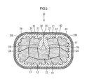
- FIG. 5 is a section showing a state where a resin material is coated to apply a waterproofing treatment in a state of FIG. 4 .
- FIG. 6 is a section showing a state where a wire barrel is waterproofed by mounting a heat shrinkable tube instead of the resin material of the first embodiment.
- FIGS. 1 to 5 A first embodiment of the present invention is described with reference to FIGS. 1 to 5 .
- a female terminal fitting 20 to be connected to an end of an aluminum wire (not shown) is illustrated in this embodiment.
- the aluminum wire is structured such that a core 12 is formed by twisting a plurality of strands 11 made of aluminum or aluminum alloy and covered by an insulation coating (not shown) made of synthetic resin.
- the female terminal fitting 20 is formed by press-working a metal plate with good electrical conductivity made of copper alloy or the like, and structured such that a wire barrel 25 and an insulation barrel 26 are provided behind a terminal connecting portion 21 substantially in the form of a rectangular tube to be electrically connected to a mating male terminal fitting (not shown).
- a resilient contact piece 23 folded back at the front edge of a bottom plate portion 22 is provided in the terminal connecting portion 21 .
- a tab of the above mating male terminal fitting is inserted into this terminal connecting portion 21 from front and resiliently comes into contact with the resilient contact piece 23 , whereby the male terminal fitting and the female terminal fitting 20 are electrically connected.
- the wire barrel 25 is of an open barrel type and connected to the bottom plate portion 22 such that left and right wide barrel pieces 25 L, 25 R rise from left and right edges of the bottom plate portion 22 while facing each other.
- the wire barrel 25 is caulked and crimped to an end of the core 12 of the aluminum wire by vertically crimping the respective barrel pieces 25 L, 25 R.
- the barrel pieces 25 L, 25 R are so flattened and crimped to the core 12 as to surround the entire circumference of the end of the core 12 while later-described corner portions 30 , 30 are butted against each other.
- the insulation barrel 26 is likewise of an open barrel type and connected to the bottom plate portion 22 such that left and right barrel pieces 26 L, 26 R narrower and taller than the barrel pieces 25 L, 25 R of the wire barrel 25 rise from the left and right edges of the bottom plate portion 22 while facing each other.
- the insulation barrel 26 is caulked and crimped to an end of an insulation coating of the aluminum wire by vertically crimping the respective barrel pieces 26 L, 26 R.
- the barrel pieces 26 L, 26 R are caulked in a so-called overlapping manner to embrace the outer periphery of the end of the insulation coating from opposite left and right sides while overlapping projecting ends thereof.
- a plurality of recesses 24 are formed on a crimping surface (inner surface in FIG. 3 ) of the wire barrel 25 . As shown in FIG. 1 , these recesses 24 are bottomed recesses having a substantially parallelogram-like opening shape.
- the core 12 bites into the interior of each recess 24 by crimping. Edges of each recess 24 break an insulation film formed on the outer surface of the core 12 during this biting, whereby the core 12 and the edges of each recess 24 are electrically conductively connected.
- a thinning portion 27 IS formed on A tip part of EACH OF the respective barrel pieces 25 L, 25 R of the wire barrel 25 to be held in contact with the core 12 .
- These thinning portions 27 are formed by being struck during press-working and extend in a front-back direction (axial direction of the wire) over the entire length from the front edges to the rear edges of the barrel pieces 25 L, 25 R. Further, as shown in FIG. 3 , the thinning portions 27 have a semicircular cross-section.
- each of the barrel pieces 25 L, 25 R is composed of an inner crimping piece 28 arranged in the core 12 and an outer crimping piece 29 arranged outside the core 12 as shown in FIG. 5 .
- the corner portion 30 is formed on an outer part between the inner and outer crimping pieces 28 , 29 which does not come into contact with the core 12 .
- This corner portion 30 is formed by bending the thinning portion 27 inwardly (toward the core 12 ), and a bending angle of the corner portion 30 is substantially a right angle and drastically smaller than in the case where the thinning portion 27 is not provided.
- parts of the respective barrel pieces 25 L, 25 R extending from the thinning portions 27 , 27 toward a base end side are formed into flat portions 31 , 31 .
- These flat portions 31 are formed between the corner portions 30 and the recesses 24 closest to the corner portions 30 .
- the flat portion 31 of one barrel piece 25 L and that of the other barrel piece 25 R are aligned and flush with each other in a horizontal direction (direction perpendicular to a crimping direction of the respective barrel pieces 25 L, 25 R).
- butting parts of the respective barrel pieces 25 L, 25 R are formed by butting the respective corner portions 30 , 30 bent substantially at a right angle against each other. In other words, the wire barrel 25 is held in a closed state by butting the respective corner portions 30 , 30 into close contact with each other.
- a resin material 40 is coated on the outer periphery of the wire barrel 25 for sealing, whereby a waterproofing treatment is applied.
- the resin material 40 is formed to have a substantially uniform thickness, and the resin material 40 does not become extremely thick even at the butting parts of the respective corner portions 30 , 30 . That is, a clearance formed between the respective corner portions 30 , 30 is made smaller by more proximately arranging the corner portions 30 , 30 having a small bending angle. Even if the resin material 40 is filled into this clearance, the thickness of the resin material 40 can be suppressed to be small.
- FIG. 2 is a section showing the wire barrel 25 in a development state, and the metal plate as a base material of the female terminal fitting 20 is punched out into a predetermined shape.
- the plurality of recesses 24 are formed by recessing on the crimping surface of the wire barrel 25 and, simultaneously, the pair of thinning portions 27 , 27 are formed by recessing on opposite left and right sides of the plurality of recesses 24 .
- the bottom plate portion 22 is folded into a substantially U shape, whereby the respective barrel pieces 25 L, 25 R rise while facing each other.
- the wire barrel 25 shown in FIG. 1 is formed and the female terminal fitting 20 is completed.
- the core 12 is placed on the bottom plate portion 22 of the wire barrel 25 and the respective barrel pieces 25 L, 25 R are caulked and crimped to surround that core 12 .
- the tips of the respective barrel pieces 25 L, 25 R come into contact with a crimping die (not shown) and the inner crimping pieces 28 are bent inwardly at the thinning portions 27 .
- the respective barrel pieces 25 L, 25 R are crimped to the core 12 .
- the thinning portions 27 are deformed to form the corner portions 30 , and the wire barrel 25 are held in the closed state by butting these corner portions 30 , 30 into close contact with each other.
- the resin material 40 is coated on the outer periphery of the wire barrel 25 as shown in FIG. 5 .
- the resin material 40 is formed to have a substantially uniform thickness and the interior of the wire barrel 25 is kept watertight. In this way, an anticorrosive effect of preventing the occurrence of electrolytic corrosion between different types of metals is exhibited.
- the clearance formed between the respective corner portions 30 , 30 can be made smaller and the thickness of the resin material 40 filled into this clearance can be suppressed to be small.
- a second embodiment of the present invention is described with reference to FIG. 6 .
- a waterproofing treatment is applied using a heat shrinkable tube 50 instead of the resin material 40 of the first embodiment. If a heating treatment is applied after the heat shrinkable tube 50 before shrinkage is mounted on a wire barrel 25 , the heat shrinkable tube 50 shrinks to make the interior of the wire barrel 25 watertight. At this time, a small clearance S is formed between butting parts of corner portions 30 , 30 and the heat shrinkable tube 50 , but this clearance S is very small and has such a size as not to permit the entrance of water. Thus, a waterproofing effect and an anticorrosive effect are not lost.
- thinning portions 27 formed into grooves extending in the front-back direction are illustrated in the above embodiments, through holes may be formed and conical thinning portions may be formed on hole edge parts of these through holes according to the present invention.
- a thinning portion may be formed only on either one of the barrel pieces according to the present invention.
- flat portions 31 , 31 are formed on the parts of the barrel pieces 25 L, 25 R extending from the thinning portions 27 , 27 toward the base end side in the above embodiments, curved portions may be provided instead of the flat portions and arranged to be aligned in flush with each other according to the present invention.
- the thinning portions 27 are formed on the sides of the barrel pieces 25 L, 25 R to be held in contact with the core 12 in the above embodiments, they may be formed on sides opposite to the core 12 according to the present invention.
- corner portions 30 having a bending angle of about 90° are illustrated as bent portions in the above embodiments, bent portions having a bending angle of about 120° may be formed instead of the corner portions 30 according to the present invention.
- the present invention may be applied to a copper wire including a core made of copper alloy or the like. Further, although the female terminal fitting is illustrated in the above embodiments, the present invention may be applied to a male terminal fitting including a tab. Further, although the twisted strands are illustrated in the above embodiments, the present invention may be applied to a straight core in which strands are not twisted.
Landscapes
- Connections Effected By Soldering, Adhesion, Or Permanent Deformation (AREA)
Abstract
Description
Claims (6)
Applications Claiming Priority (3)
| Application Number | Priority Date | Filing Date | Title |
|---|---|---|---|
| JP2012011013A JP2013149564A (en) | 2012-01-23 | 2012-01-23 | Terminal fitting |
| JP2012-11013 | 2012-01-23 | ||
| PCT/JP2012/082146 WO2013111465A1 (en) | 2012-01-23 | 2012-12-12 | Terminal fitting |
Publications (2)
| Publication Number | Publication Date |
|---|---|
| US20150244084A1 US20150244084A1 (en) | 2015-08-27 |
| US9147944B2 true US9147944B2 (en) | 2015-09-29 |
Family
ID=48873206
Family Applications (1)
| Application Number | Title | Priority Date | Filing Date |
|---|---|---|---|
| US14/373,189 Expired - Fee Related US9147944B2 (en) | 2012-01-23 | 2012-12-12 | Terminal fitting |
Country Status (6)
| Country | Link |
|---|---|
| US (1) | US9147944B2 (en) |
| JP (1) | JP2013149564A (en) |
| KR (1) | KR101629125B1 (en) |
| CN (1) | CN104067446B (en) |
| IN (1) | IN2014DN05806A (en) |
| WO (1) | WO2013111465A1 (en) |
Cited By (5)
| Publication number | Priority date | Publication date | Assignee | Title |
|---|---|---|---|---|
| US20170005417A1 (en) * | 2014-04-04 | 2017-01-05 | Yazaki Corporation | Structure for connecting crimping terminal and electric wire |
| US20180261931A1 (en) * | 2015-12-16 | 2018-09-13 | Yazaki Corporation | Crimp terminal |
| US20190044252A1 (en) * | 2017-08-01 | 2019-02-07 | Autonetworks Technologies, Ltd. | Wire with terminal |
| US10424849B2 (en) | 2015-05-21 | 2019-09-24 | Aptiv Technologies Limited | Crimp connection system for electrical cables comprising a fastening sleeve |
| US12100924B2 (en) | 2018-06-29 | 2024-09-24 | Te Connectivity Germany Gmbh | Crimp and method for producing a crimp |
Families Citing this family (7)
| Publication number | Priority date | Publication date | Assignee | Title |
|---|---|---|---|---|
| US10128581B2 (en) * | 2014-06-19 | 2018-11-13 | Fujikura Ltd. | Crimp terminal |
| JP2017033776A (en) * | 2015-08-03 | 2017-02-09 | 矢崎総業株式会社 | Crimp terminal, method of manufacturing the same, electric wire and wiring harness |
| JP6532160B2 (en) * | 2015-08-04 | 2019-06-19 | タイコエレクトロニクスジャパン合同会社 | Electrical terminal |
| JP2017204443A (en) * | 2016-05-13 | 2017-11-16 | 株式会社オートネットワーク技術研究所 | Wire with terminal and terminal crimp method to wire |
| DE102017105682A1 (en) | 2017-03-16 | 2018-09-20 | Te Connectivity Germany Gmbh | Contact carrier, electrical contact device and method for producing a ready-made cable |
| EP3588679B1 (en) * | 2018-06-29 | 2023-09-27 | TE Connectivity Germany GmbH | Crimp and method for producing a crimp |
| DE102019109460A1 (en) * | 2019-04-10 | 2020-10-15 | Te Connectivity Germany Gmbh | Crimp contact |
Citations (13)
| Publication number | Priority date | Publication date | Assignee | Title |
|---|---|---|---|---|
| US3781459A (en) * | 1972-07-20 | 1973-12-25 | Anderson Electric Corp | Compression connector for electrical conductors |
| JPS6035471A (en) | 1983-08-03 | 1985-02-23 | Agency Of Ind Science & Technol | Electrode for fuel cell |
| JPS6148658A (en) | 1984-08-16 | 1986-03-10 | Fuji Heavy Ind Ltd | Speed-change controller for continuously variable transmission |
| JPS6443980A (en) | 1987-08-11 | 1989-02-16 | Yazaki Corp | Electric contact maker |
| US5245132A (en) * | 1991-06-19 | 1993-09-14 | Minnesota Technical Research, Inc. | Noble plated tungsten corona wire for copy machines or xerography technology machines |
| JPH11238532A (en) | 1997-12-09 | 1999-08-31 | Siemens Ag | Crimp contact for plug-in mechanism |
| US20010016460A1 (en) * | 2000-02-02 | 2001-08-23 | Takashii Koide | Terminal fitting |
| JP2005050736A (en) | 2003-07-30 | 2005-02-24 | Furukawa Electric Co Ltd:The | Method of manufacturing terminal crimping structure to aluminum wire and aluminum wire with terminal |
| US7306495B2 (en) | 2003-07-30 | 2007-12-11 | The Furukawa Electric Co., Ltd. | Terminal crimping structure and terminal crimping method onto aluminum electric-wire and producing method of aluminum electric-wire with terminal |
| US20090137144A1 (en) | 2007-11-27 | 2009-05-28 | Yazaki Corporation | Press-clamping structure and press-clamping terminal |
| JP2009152162A (en) | 2007-11-27 | 2009-07-09 | Yazaki Corp | Crimping structure of crimp terminal to electric wire, and crimping terminal |
| US20110067239A1 (en) * | 2009-09-18 | 2011-03-24 | Delphi Technologies, Inc. | Method of making an improved electrical connection for a sealed cable core and a terminal with conformal coating |
| US9054431B2 (en) * | 2009-10-28 | 2015-06-09 | Yazaki Corporation | Press bond terminal |
Family Cites Families (3)
| Publication number | Priority date | Publication date | Assignee | Title |
|---|---|---|---|---|
| JPS6035471U (en) * | 1983-08-17 | 1985-03-11 | 日本航空電子工業株式会社 | Contact notch structure |
| JPH0129974Y2 (en) * | 1984-08-31 | 1989-09-12 | ||
| WO2009101965A1 (en) * | 2008-02-15 | 2009-08-20 | Autonetworks Technologies, Ltd. | Terminal fitting and wire harness |
-
2012
- 2012-01-23 JP JP2012011013A patent/JP2013149564A/en active Pending
- 2012-12-12 US US14/373,189 patent/US9147944B2/en not_active Expired - Fee Related
- 2012-12-12 CN CN201280067633.3A patent/CN104067446B/en not_active Expired - Fee Related
- 2012-12-12 KR KR1020147020615A patent/KR101629125B1/en active IP Right Grant
- 2012-12-12 WO PCT/JP2012/082146 patent/WO2013111465A1/en active Application Filing
- 2012-12-12 IN IN5806DEN2014 patent/IN2014DN05806A/en unknown
Patent Citations (14)
| Publication number | Priority date | Publication date | Assignee | Title |
|---|---|---|---|---|
| US3781459A (en) * | 1972-07-20 | 1973-12-25 | Anderson Electric Corp | Compression connector for electrical conductors |
| JPS6035471A (en) | 1983-08-03 | 1985-02-23 | Agency Of Ind Science & Technol | Electrode for fuel cell |
| JPS6148658A (en) | 1984-08-16 | 1986-03-10 | Fuji Heavy Ind Ltd | Speed-change controller for continuously variable transmission |
| JPS6443980A (en) | 1987-08-11 | 1989-02-16 | Yazaki Corp | Electric contact maker |
| US5245132A (en) * | 1991-06-19 | 1993-09-14 | Minnesota Technical Research, Inc. | Noble plated tungsten corona wire for copy machines or xerography technology machines |
| JPH11238532A (en) | 1997-12-09 | 1999-08-31 | Siemens Ag | Crimp contact for plug-in mechanism |
| US6059616A (en) | 1997-12-09 | 2000-05-09 | Siemens Aktiengesellschaft | Crimp contact for plug-in systems |
| US20010016460A1 (en) * | 2000-02-02 | 2001-08-23 | Takashii Koide | Terminal fitting |
| JP2005050736A (en) | 2003-07-30 | 2005-02-24 | Furukawa Electric Co Ltd:The | Method of manufacturing terminal crimping structure to aluminum wire and aluminum wire with terminal |
| US7306495B2 (en) | 2003-07-30 | 2007-12-11 | The Furukawa Electric Co., Ltd. | Terminal crimping structure and terminal crimping method onto aluminum electric-wire and producing method of aluminum electric-wire with terminal |
| US20090137144A1 (en) | 2007-11-27 | 2009-05-28 | Yazaki Corporation | Press-clamping structure and press-clamping terminal |
| JP2009152162A (en) | 2007-11-27 | 2009-07-09 | Yazaki Corp | Crimping structure of crimp terminal to electric wire, and crimping terminal |
| US20110067239A1 (en) * | 2009-09-18 | 2011-03-24 | Delphi Technologies, Inc. | Method of making an improved electrical connection for a sealed cable core and a terminal with conformal coating |
| US9054431B2 (en) * | 2009-10-28 | 2015-06-09 | Yazaki Corporation | Press bond terminal |
Non-Patent Citations (2)
| Title |
|---|
| International Search Report dated Feb. 26, 2013. |
| Written Opinion Report dated Feb. 26, 2014. |
Cited By (8)
| Publication number | Priority date | Publication date | Assignee | Title |
|---|---|---|---|---|
| US20170005417A1 (en) * | 2014-04-04 | 2017-01-05 | Yazaki Corporation | Structure for connecting crimping terminal and electric wire |
| US9774099B2 (en) * | 2014-04-04 | 2017-09-26 | Yazaki Corporation | Structure for connecting crimping terminal and electric wire |
| US10424849B2 (en) | 2015-05-21 | 2019-09-24 | Aptiv Technologies Limited | Crimp connection system for electrical cables comprising a fastening sleeve |
| US20180261931A1 (en) * | 2015-12-16 | 2018-09-13 | Yazaki Corporation | Crimp terminal |
| US10763597B2 (en) * | 2015-12-16 | 2020-09-01 | Yazaki Corporation | Crimp terminal having a groove for facilitating crimping workability and a water stop member |
| US20190044252A1 (en) * | 2017-08-01 | 2019-02-07 | Autonetworks Technologies, Ltd. | Wire with terminal |
| US10498048B2 (en) * | 2017-08-01 | 2019-12-03 | Autonetworks Technologies, Ltd. | Wire with terminal having a core crimping portion with enlarged diameter portion and a recess in the enlarged diameter portion |
| US12100924B2 (en) | 2018-06-29 | 2024-09-24 | Te Connectivity Germany Gmbh | Crimp and method for producing a crimp |
Also Published As
| Publication number | Publication date |
|---|---|
| KR20140111680A (en) | 2014-09-19 |
| KR101629125B1 (en) | 2016-06-09 |
| CN104067446A (en) | 2014-09-24 |
| JP2013149564A (en) | 2013-08-01 |
| IN2014DN05806A (en) | 2015-05-15 |
| WO2013111465A1 (en) | 2013-08-01 |
| CN104067446B (en) | 2017-07-18 |
| US20150244084A1 (en) | 2015-08-27 |
Similar Documents
| Publication | Publication Date | Title |
|---|---|---|
| US9147944B2 (en) | Terminal fitting | |
| US9136628B2 (en) | Crimp type terminal fitting | |
| US8876564B2 (en) | Connection structure of crimping terminal to electric wire | |
| US9711872B2 (en) | Crimp terminal and structure for connecting crimp terminal and wire | |
| US9356388B2 (en) | Terminal-attached wire and terminal | |
| US8944862B2 (en) | Structure of connection of crimping terminal to electric wire | |
| US9502784B2 (en) | Terminal attached aluminum electric wire | |
| WO2011142205A1 (en) | Connection structure for crimp terminal wire | |
| JP5418332B2 (en) | Electric wire with terminal bracket | |
| US9608339B2 (en) | Crimped terminal attached aluminum electric wire | |
| JP2011216395A (en) | Wire connection structure of crimp terminal | |
| US9509085B2 (en) | Wire with corrosion-resistant terminal | |
| WO2014014104A1 (en) | Crimp terminal, connected structure, and connector | |
| JP6709818B2 (en) | Wire with terminal | |
| JP5814711B2 (en) | Connection structure | |
| WO2011115005A1 (en) | Cable having terminal fitting and manufacturing method for same | |
| US10644415B2 (en) | Terminal-equipped wire and method for crimping terminal onto wire | |
| JP2010225529A (en) | Electric wire with terminal metal fitting | |
| JP2010176886A (en) | Wire connecting sleeve, repair wire, method of manufacturing the wire connection sleeve, and wire connecting method | |
| US20180062277A1 (en) | Wire with terminal and terminal | |
| JP6016999B2 (en) | Connection structure | |
| JP2014164930A (en) | Terminal with electric wire and manufacturing method therefor | |
| JP6820294B2 (en) | Wire with terminal | |
| JP2015222737A5 (en) | ||
| JP7509518B2 (en) | Electric wire with terminal and manufacturing device for electric wire with terminal |
Legal Events
| Date | Code | Title | Description |
|---|---|---|---|
| AS | Assignment |
Owner name: SUMITOMO ELECTRIC INDUSTRIES, LTD., JAPAN Free format text: ASSIGNMENT OF ASSIGNORS INTEREST;ASSIGNORS:AIZAWA, TAKESHI;MORIKAWA, SATOSHI;UCHIYAMA, YOSHIHIRO;AND OTHERS;SIGNING DATES FROM 20140603 TO 20140610;REEL/FRAME:033343/0359 Owner name: SUMITOMO WIRING SYSTEMS, LTD., JAPAN Free format text: ASSIGNMENT OF ASSIGNORS INTEREST;ASSIGNORS:AIZAWA, TAKESHI;MORIKAWA, SATOSHI;UCHIYAMA, YOSHIHIRO;AND OTHERS;SIGNING DATES FROM 20140603 TO 20140610;REEL/FRAME:033343/0359 Owner name: AUTONETWORKS TECHNOLOGIES, LTD, JAPAN Free format text: ASSIGNMENT OF ASSIGNORS INTEREST;ASSIGNORS:AIZAWA, TAKESHI;MORIKAWA, SATOSHI;UCHIYAMA, YOSHIHIRO;AND OTHERS;SIGNING DATES FROM 20140603 TO 20140610;REEL/FRAME:033343/0359 |
|
| STCF | Information on status: patent grant |
Free format text: PATENTED CASE |
|
| MAFP | Maintenance fee payment |
Free format text: PAYMENT OF MAINTENANCE FEE, 4TH YEAR, LARGE ENTITY (ORIGINAL EVENT CODE: M1551); ENTITY STATUS OF PATENT OWNER: LARGE ENTITY Year of fee payment: 4 |
|
| FEPP | Fee payment procedure |
Free format text: MAINTENANCE FEE REMINDER MAILED (ORIGINAL EVENT CODE: REM.); ENTITY STATUS OF PATENT OWNER: LARGE ENTITY |
|
| LAPS | Lapse for failure to pay maintenance fees |
Free format text: PATENT EXPIRED FOR FAILURE TO PAY MAINTENANCE FEES (ORIGINAL EVENT CODE: EXP.); ENTITY STATUS OF PATENT OWNER: LARGE ENTITY |
|
| STCH | Information on status: patent discontinuation |
Free format text: PATENT EXPIRED DUE TO NONPAYMENT OF MAINTENANCE FEES UNDER 37 CFR 1.362 |
|
| FP | Lapsed due to failure to pay maintenance fee |
Effective date: 20230929 |