WO2014115754A1 - 正極活物質及び該活物質を用いたリチウム二次電池 - Google Patents
正極活物質及び該活物質を用いたリチウム二次電池 Download PDFInfo
- Publication number
- WO2014115754A1 WO2014115754A1 PCT/JP2014/051231 JP2014051231W WO2014115754A1 WO 2014115754 A1 WO2014115754 A1 WO 2014115754A1 JP 2014051231 W JP2014051231 W JP 2014051231W WO 2014115754 A1 WO2014115754 A1 WO 2014115754A1
- Authority
- WO
- WIPO (PCT)
- Prior art keywords
- positive electrode
- active material
- electrode active
- battery
- lithium secondary
- Prior art date
- Legal status (The legal status is an assumption and is not a legal conclusion. Google has not performed a legal analysis and makes no representation as to the accuracy of the status listed.)
- Ceased
Links
Images



Classifications
-
- H—ELECTRICITY
- H01—ELECTRIC ELEMENTS
- H01M—PROCESSES OR MEANS, e.g. BATTERIES, FOR THE DIRECT CONVERSION OF CHEMICAL ENERGY INTO ELECTRICAL ENERGY
- H01M4/00—Electrodes
- H01M4/02—Electrodes composed of, or comprising, active material
- H01M4/36—Selection of substances as active materials, active masses, active liquids
- H01M4/48—Selection of substances as active materials, active masses, active liquids of inorganic oxides or hydroxides
- H01M4/50—Selection of substances as active materials, active masses, active liquids of inorganic oxides or hydroxides of manganese
- H01M4/505—Selection of substances as active materials, active masses, active liquids of inorganic oxides or hydroxides of manganese of mixed oxides or hydroxides containing manganese for inserting or intercalating light metals, e.g. LiMn2O4 or LiMn2OxFy
-
- H—ELECTRICITY
- H01—ELECTRIC ELEMENTS
- H01M—PROCESSES OR MEANS, e.g. BATTERIES, FOR THE DIRECT CONVERSION OF CHEMICAL ENERGY INTO ELECTRICAL ENERGY
- H01M4/00—Electrodes
- H01M4/02—Electrodes composed of, or comprising, active material
- H01M4/13—Electrodes for accumulators with non-aqueous electrolyte, e.g. for lithium-accumulators; Processes of manufacture thereof
- H01M4/131—Electrodes based on mixed oxides or hydroxides, or on mixtures of oxides or hydroxides, e.g. LiCoOx
-
- H—ELECTRICITY
- H01—ELECTRIC ELEMENTS
- H01M—PROCESSES OR MEANS, e.g. BATTERIES, FOR THE DIRECT CONVERSION OF CHEMICAL ENERGY INTO ELECTRICAL ENERGY
- H01M4/00—Electrodes
- H01M4/02—Electrodes composed of, or comprising, active material
- H01M4/36—Selection of substances as active materials, active masses, active liquids
- H01M4/362—Composites
- H01M4/366—Composites as layered products
-
- H—ELECTRICITY
- H01—ELECTRIC ELEMENTS
- H01M—PROCESSES OR MEANS, e.g. BATTERIES, FOR THE DIRECT CONVERSION OF CHEMICAL ENERGY INTO ELECTRICAL ENERGY
- H01M4/00—Electrodes
- H01M4/02—Electrodes composed of, or comprising, active material
- H01M4/36—Selection of substances as active materials, active masses, active liquids
- H01M4/48—Selection of substances as active materials, active masses, active liquids of inorganic oxides or hydroxides
- H01M4/52—Selection of substances as active materials, active masses, active liquids of inorganic oxides or hydroxides of nickel, cobalt or iron
- H01M4/525—Selection of substances as active materials, active masses, active liquids of inorganic oxides or hydroxides of nickel, cobalt or iron of mixed oxides or hydroxides containing iron, cobalt or nickel for inserting or intercalating light metals, e.g. LiNiO2, LiCoO2 or LiCoOxFy
-
- H—ELECTRICITY
- H01—ELECTRIC ELEMENTS
- H01M—PROCESSES OR MEANS, e.g. BATTERIES, FOR THE DIRECT CONVERSION OF CHEMICAL ENERGY INTO ELECTRICAL ENERGY
- H01M50/00—Constructional details or processes of manufacture of the non-active parts of electrochemical cells other than fuel cells, e.g. hybrid cells
- H01M50/50—Current conducting connections for cells or batteries
- H01M50/572—Means for preventing undesired use or discharge
-
- H—ELECTRICITY
- H01—ELECTRIC ELEMENTS
- H01M—PROCESSES OR MEANS, e.g. BATTERIES, FOR THE DIRECT CONVERSION OF CHEMICAL ENERGY INTO ELECTRICAL ENERGY
- H01M10/00—Secondary cells; Manufacture thereof
- H01M10/05—Accumulators with non-aqueous electrolyte
- H01M10/052—Li-accumulators
-
- H—ELECTRICITY
- H01—ELECTRIC ELEMENTS
- H01M—PROCESSES OR MEANS, e.g. BATTERIES, FOR THE DIRECT CONVERSION OF CHEMICAL ENERGY INTO ELECTRICAL ENERGY
- H01M10/00—Secondary cells; Manufacture thereof
- H01M10/42—Methods or arrangements for servicing or maintenance of secondary cells or secondary half-cells
- H01M10/4235—Safety or regulating additives or arrangements in electrodes, separators or electrolyte
-
- H—ELECTRICITY
- H01—ELECTRIC ELEMENTS
- H01M—PROCESSES OR MEANS, e.g. BATTERIES, FOR THE DIRECT CONVERSION OF CHEMICAL ENERGY INTO ELECTRICAL ENERGY
- H01M4/00—Electrodes
- H01M4/02—Electrodes composed of, or comprising, active material
- H01M2004/021—Physical characteristics, e.g. porosity, surface area
-
- H—ELECTRICITY
- H01—ELECTRIC ELEMENTS
- H01M—PROCESSES OR MEANS, e.g. BATTERIES, FOR THE DIRECT CONVERSION OF CHEMICAL ENERGY INTO ELECTRICAL ENERGY
- H01M4/00—Electrodes
- H01M4/02—Electrodes composed of, or comprising, active material
- H01M2004/026—Electrodes composed of, or comprising, active material characterised by the polarity
- H01M2004/028—Positive electrodes
-
- H—ELECTRICITY
- H01—ELECTRIC ELEMENTS
- H01M—PROCESSES OR MEANS, e.g. BATTERIES, FOR THE DIRECT CONVERSION OF CHEMICAL ENERGY INTO ELECTRICAL ENERGY
- H01M2200/00—Safety devices for primary or secondary batteries
- H01M2200/20—Pressure-sensitive devices
-
- H—ELECTRICITY
- H01—ELECTRIC ELEMENTS
- H01M—PROCESSES OR MEANS, e.g. BATTERIES, FOR THE DIRECT CONVERSION OF CHEMICAL ENERGY INTO ELECTRICAL ENERGY
- H01M2220/00—Batteries for particular applications
- H01M2220/20—Batteries in motive systems, e.g. vehicle, ship, plane
-
- H—ELECTRICITY
- H01—ELECTRIC ELEMENTS
- H01M—PROCESSES OR MEANS, e.g. BATTERIES, FOR THE DIRECT CONVERSION OF CHEMICAL ENERGY INTO ELECTRICAL ENERGY
- H01M50/00—Constructional details or processes of manufacture of the non-active parts of electrochemical cells other than fuel cells, e.g. hybrid cells
- H01M50/50—Current conducting connections for cells or batteries
- H01M50/572—Means for preventing undesired use or discharge
- H01M50/574—Devices or arrangements for the interruption of current
- H01M50/578—Devices or arrangements for the interruption of current in response to pressure
-
- Y—GENERAL TAGGING OF NEW TECHNOLOGICAL DEVELOPMENTS; GENERAL TAGGING OF CROSS-SECTIONAL TECHNOLOGIES SPANNING OVER SEVERAL SECTIONS OF THE IPC; TECHNICAL SUBJECTS COVERED BY FORMER USPC CROSS-REFERENCE ART COLLECTIONS [XRACs] AND DIGESTS
- Y02—TECHNOLOGIES OR APPLICATIONS FOR MITIGATION OR ADAPTATION AGAINST CLIMATE CHANGE
- Y02E—REDUCTION OF GREENHOUSE GAS [GHG] EMISSIONS, RELATED TO ENERGY GENERATION, TRANSMISSION OR DISTRIBUTION
- Y02E60/00—Enabling technologies; Technologies with a potential or indirect contribution to GHG emissions mitigation
- Y02E60/10—Energy storage using batteries
Definitions
- the present invention relates to a positive electrode active material for a lithium secondary battery. Furthermore, the present invention relates to a lithium secondary battery using the positive electrode active material. Note that this international application claims priority based on Japanese Patent Application No. 2013-11524 filed on January 24, 2013, the entire contents of which are incorporated herein by reference. Yes.
- Lithium secondary batteries are smaller, lighter and have higher energy density than existing batteries, and have excellent input / output density. For this reason, in recent years, it is preferably used as a so-called portable power source for personal computers and portable terminals, and a high-output power source for mounting on vehicles.
- Such a lithium secondary battery is generally used in a state in which the voltage is controlled so as to be within a predetermined region (for example, 3.0 V to 4.2 V).
- a current higher than usual is supplied to the battery due to an erroneous operation or the like.
- the battery may be overcharged beyond a predetermined voltage. Therefore, in order to cope with such overcharge, a battery having a current interrupt device (hereinafter, sometimes referred to as “CID”) that interrupts the charging current when the pressure in the battery case becomes a predetermined value or more. Proposed.
- CID current interrupt device
- a non-aqueous solvent or the like contained in the electrolyte is electrolyzed and gas is generated.
- Patent Document 1 describes that a polymerizable compound (or a polymer) is added to a non-aqueous electrolyte and a carbon dioxide generator is added to a positive electrode active material layer. ing. According to this configuration, the polymerizable compound in the electrolytic solution reacts during overcharge to generate hydrogen ions, and carbon ions can be generated by the reaction between the hydrogen ions and the carbon dioxide generator. According to Patent Document 1, the CID can be operated more quickly.
- the density of the positive electrode active material layer is increased by adjusting the particle size of the positive electrode active material, the voids in the positive electrode active material layer are reduced, so that the contact area between the electrode and the electrolyte solution There is a risk that gas generation during overcharge may be moderated. Further, since the diffusion path of the generated gas is narrowed, there is a possibility that the gas is not smoothly discharged from the electrode active material layer.
- the objective is producing the positive electrode which can make the outstanding battery performance (for example, high energy density) and the high reliability (overcharge tolerance) at the time of overcharge compatible. It is in providing the positive electrode active material for.
- Another related object is a lithium secondary battery equipped with a (pressure-actuated) current cut-off mechanism that operates by increasing the internal pressure of the battery, which combines excellent battery performance and reliability during overcharge. It is to provide a secondary battery.
- a positive electrode active material for a lithium secondary battery is provided.
- the positive electrode active material for a lithium secondary battery disclosed here is a lithium transition metal oxide having a layered structure represented by the general formula: Li 1 + ⁇ Ni x Co y Mn z Ca ⁇ M ⁇ O 2 It may be expressed as “LNCMC oxide”).
- LNCMC oxide Li 1 + ⁇ Ni x Co y Mn z Ca ⁇ M ⁇ O 2 It may be expressed as “LNCMC oxide”.
- ⁇ , x, y, z, ⁇ , ⁇ are ⁇ 0.05 ⁇ ⁇ ⁇ 0.2, x + y + z + ⁇ + ⁇ 1, 0.3 ⁇ x ⁇ 0.7, 0.1 ⁇ y ⁇ 0.4.
- M is sodium (Na), magnesium (Mg), aluminum (Al), titanium (Ti), vanadium (V), chromium (Cr), zirconium (Zr), niobium (Nb), molybdenum
- M is sodium (Na), magnesium (Mg), aluminum (Al), titanium (Ti), vanadium (V), chromium (Cr), zirconium (Zr), niobium (Nb), molybdenum
- M is sodium (Na), magnesium (Mg), aluminum (Al), titanium (Ti), vanadium (V), chromium (Cr), zirconium (Zr), niobium (Nb), molybdenum
- the tap density of the positive electrode active material disclosed here is 1.8 g / cm 3 or more and 2.5 g / cm 3 or less.
- Lithium transition metal oxides containing Ni, Co, and Mn as constituent elements are excellent in thermal stability and have a higher theoretical energy density than other oxides. For this reason, high battery performance (for example, energy density and cycling characteristics) is realizable.
- high battery performance for example, energy density and cycling characteristics
- Ca as a constituent element
- a large amount of gas can be generated quickly during overcharge.
- the tap density of the positive electrode active material within the above range, a discharge path for the generated gas can be ensured, and the gas generated during overcharge can be quickly discharged out of the electrode body. For this reason, the CID can be accurately operated at the initial stage of overcharge. Therefore, according to the positive electrode active material disclosed here, it is possible to realize both excellent battery performance (for example, high energy density and cycle characteristics) and reliability during overcharge.
- lithium secondary battery refers to all secondary batteries that use lithium ions as charge carriers (electrolyte ions) and are charged and discharged by movement of lithium ions between the positive and negative electrodes.
- the average particle diameter D 50 corresponding to 50% cumulative from the fine particle side is 5 ⁇ m or more and 9 ⁇ m.
- the particle size D 10 corresponding to 10% cumulative from the fine particle side, the particle size D 90 corresponding to 90% cumulative from the fine particle side, and the average particle size D 50 are as follows: (D 90 -D 10 ) / D 50 ⁇ 0.7.
- a suitable conductive path conductive path
- resistance for example, charge transfer resistance
- the above relational expression can be an index representing the spread of the particle size distribution.
- the spread of the particle size distribution is made small so that the relational expression is 0.7 or less, that is, the positive electrode active material particles are made homogeneous.
- grain can be equalized, and the local deterioration of the positive electrode active material accompanying charging / discharging can be suppressed. Therefore, it is possible to suitably realize a battery that can exhibit excellent battery performance (for example, energy density, input / output density, cycle characteristics) during normal use, and can quickly generate gas and operate CID during overcharge. .
- the “average particle size” means a particle size corresponding to 50% cumulative from the fine particle side in a volume-based particle size distribution measured by a particle size distribution measurement based on a general laser diffraction / light scattering method. (Also referred to as D 50 , median diameter).
- D 50 median diameter
- D 10 mean particle sizes corresponding to 10% accumulation and 90% accumulation from the fine particle side, respectively, similarly to the average particle diameter.
- the positive electrode active material preferably has a hollow structure having a shell portion made of a lithium transition metal oxide having a layered structure and a hollow portion formed therein.
- material exchange for example, insertion and extraction of lithium ions
- a lithium secondary battery including such a positive electrode active material can exhibit high input / output characteristics (particularly, a high output density in a low SOC region where ion diffusion into the positive electrode active material is rate limiting), for example, a wide SOC range. Can produce a desired output.
- the gas generated during overcharge may not be smoothly discharged from the positive electrode active material layer.
- the positive electrode active material disclosed here includes Ca as a constituent element to improve the reactivity during overcharge, the positive electrode active material has a nearly hollow structure (for example, a hollow structure).
- CID can be generated at an early stage by generating a large amount of gas quickly. That is, excellent battery performance (for example, input / output density) and reliability during overcharging can be achieved at a higher level.
- the thickness of the shell portion based on observation with an electron microscope is 2 ⁇ m or less. By suppressing the thickness of the shell and the primary particle size to be small, even higher input / output characteristics can be exhibited. Moreover, it is preferable that the thickness based on the electron microscope observation of the said shell part is 0.1 micrometer or more. By setting it as this thickness, high durability can be ensured with respect to stress that can be applied at the time of manufacture or use of the battery, expansion and contraction of the positive electrode active material accompanying charging and discharging, and the like. Therefore, a battery using a positive electrode active material that satisfies the thickness of the shell can stably exhibit excellent performance over a long period of time.
- the “positive electrode active material having a hollow structure” means the ratio of the above-mentioned hollow portion in the apparent cross-sectional area of the active material in a cross section obtained by cutting the positive electrode active material at random positions (particles described later) It shall mean a positive electrode active material having a porosity of 5% or more.
- SOC refers to the state of charge of a battery based on a voltage range in which the battery is normally used. For example, the state of charge based on the rated capacity measured under the condition that the voltage between terminals (open circuit voltage (OCV)) is 4.1 V (upper limit voltage) to 3.0 V (lower limit voltage) And
- Such positive electrode active material particles preferably have a through-hole penetrating the shell (hereinafter, a hollow structure having a through-hole in the shell may be referred to as a “perforated hollow structure”).
- the positive electrode active material having a perforated hollow structure can easily be impregnated with an electrolytic solution in a hollow portion, and can perform material exchange with the electrolytic solution more efficiently than the hollow structure. Therefore, output characteristics (particularly, output characteristics in a low SOC region) are improved, and a desired output can be exhibited in a wider SOC range. For this reason, a battery including such a positive electrode active material can achieve both battery performance (for example, input / output characteristics) and reliability during overcharge at a higher level.
- the crystallite diameter r based on X-ray diffraction of the positive electrode active material is preferably 0.05 ⁇ m or more and 0.2 ⁇ m or less.
- a lithium secondary battery in which an electrode body including a positive electrode and a negative electrode and a non-aqueous electrolyte are accommodated in a battery case.
- the battery case includes a current interruption mechanism that operates when the internal pressure of the battery case increases.
- the positive electrode includes any positive electrode active material disclosed herein.
- the lithium secondary battery disclosed herein can exhibit high reliability during overcharge while maintaining good battery performance. For example, the energy density and input / output density are high, for example, a desired output can be exhibited in a wide SOC range, and the CID can operate appropriately. Therefore, taking advantage of this feature, for example, it can be suitably used as a power source (drive power source) of a vehicle.
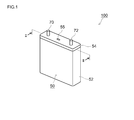
- FIG. 1 is a perspective view schematically showing the outer shape of a lithium secondary battery according to an embodiment.
- FIG. 2 is a diagram schematically showing a cross-sectional structure taken along line II-II in FIG.
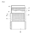
- FIG. 3 is a schematic diagram showing the configuration of the wound electrode body of FIG.
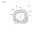
- FIG. 4 is a diagram schematically showing a cross-sectional structure of a positive electrode active material according to an embodiment.
- FIG. 5 is an SEM observation image of the positive electrode active material according to one embodiment.
- FIG. 6 is a cross-sectional SEM observation image of the positive electrode active material according to an embodiment.
- FIG. 7 is a graph showing the correlation between the Ca addition ratio in the lithium transition metal oxide and the battery characteristics.
- FIG. 8 is a graph showing the correlation between the tap density and the characteristics of the positive electrode active material.
- the positive electrode active material disclosed here (in the case of a positive electrode active material having a hollow structure to be described later) has a general formula: Li 1 + ⁇ Ni x Co y Mn z Ca ⁇ M ⁇ O 2 And a lithium transition metal oxide having a layered crystal structure (typically a layered rock salt structure belonging to a hexagonal system).
- a lithium transition metal oxide having a layered crystal structure typically a layered rock salt structure belonging to a hexagonal system.
- Li and Ca can form a compound. According to the study by the present inventors, the formation of such a compound can suppress the polymerization of the non-aqueous electrolyte and reduce the amount of alkali (for example, lithium hydroxide (LiOH)) on the surface of the positive electrode active material. it can.
- the reactivity of the gas generating agent at the time of overcharging can be improved compared with the case where the above compound is included as an additive (gas generating agent) in the non-aqueous electrolyte, for example. It can be generated quickly.
- “consisting of a lithium transition metal oxide” means that the positive electrode active material is substantially composed of the above oxide, and that inevitable contamination of impurities is acceptable.
- the above ⁇ is a real number satisfying ⁇ 0.05 ⁇ ⁇ ⁇ 0.2 from the viewpoint of suppressing an increase in resistance.
- the above x, y, z, ⁇ , ⁇ are real numbers satisfying x + y + z + ⁇ + ⁇ 1 (typically 0.95 to 1.02, for example, 1 to 1.02, 1 for the purpose).
- x, y, and z are typically 0.98 ⁇ x + y + z ⁇ 0.9998, where x is a real number that satisfies 0.3 ⁇ x ⁇ 0.7, and y is 0.1 ⁇ y ⁇ 0. .4, and z is a real number that satisfies 0.1 ⁇ z ⁇ 0.4.
- x and z are approximately the same (for example, the difference between x and z is 0.1 or less), that is, the amount of Ni and the amount of Mn are approximately equal (for example, the difference between the amount of Ni and the amount of Mn is 10% or less).
- x, y, and z are approximately the same (for example, the difference between x, y, and z is 0.1 or less), that is, the amounts of Ni, Co, and Mn are approximately equal. It is equivalent (for example, the difference between the Ni content, the Co content, and the Mn content is 10% or less).
- An LNCMC oxide having such a composition is preferable because it exhibits excellent thermal stability and battery characteristics.
- ⁇ and ⁇ are ratios of substitutional elements in the LNCMC oxide, and are real numbers satisfying 0.0002 ⁇ ⁇ + ⁇ ⁇ 0.02 from the viewpoint of maintaining a high energy density.
- ⁇ is a real number that satisfies 0.0002 ⁇ ⁇ ⁇ 0.0025 (typically 0.0005 ⁇ ⁇ ⁇ 0.002, eg, 0.001 ⁇ ⁇ ⁇ 0.002), and ⁇ is It is a real number that satisfies 0 ⁇ ⁇ ⁇ 0.0198.
- An LNCMC oxide having such a composition is preferable because it exhibits excellent thermal stability and battery characteristics.
- M is one or more elements selected from Na, Mg, Al, Ti, V, Cr, Zr, Nb, Mo, Hf, Ta, and W.
- O oxygen
- the composition ratio of O (oxygen) is shown as 2, but this numerical value should not be interpreted strictly, and there is some variation in composition. (Typically included in the range of 1.95 or more and 2.05 or less).
- the tap density of the positive electrode active material disclosed herein 1.8 g / cm 3 or more (preferably 1.85 g / cm 3 or more, more preferably 1.88 g / cm 3 or more).
- the ratio of the positive electrode active material contained in a positive electrode active material layer can be raised, ie, the battery capacity (energy density) per unit volume can be raised.
- the tap density of the positive electrode active material 2.5 g / cm 3 or less (preferably 2.45 g / cm 3 or less, more preferably 2.41 g / cm 3 or less).
- an appropriate gap can be maintained in the positive electrode active material layer, so that the electrolytic solution can be easily immersed, and the diffusion resistance of lithium ions in the positive electrode active material layer can be kept low. For this reason, insertion and extraction of lithium ions can be performed efficiently, and output characteristics (particularly, output characteristics in a low SOC region) can be improved.
- the gas generated during overcharging can be quickly exhausted outside the electrode body, and the CID can be activated quickly.
- the average particle diameter (secondary particle diameter) of the positive electrode active material can be, for example, 3 ⁇ m or more from the viewpoint of securing a suitable void in the positive electrode active material layer.
- it is particularly preferably 5 ⁇ m or more (typically 5.5 ⁇ m or more).
- the average particle size is preferably about 10 ⁇ m or less, and more preferably about 9 ⁇ m or less (typically 8.5 ⁇ m or less).
- the average particle size and the tap density described above are generally correlated, and if there is no difference in raw materials and manufacturing methods, the average particle size is generally The tap density tends to increase as the diameter increases. That is, by setting the average particle size within the above range, it is possible to suitably realize a battery that can achieve both battery performance (for example, energy density and input / output density) and reliability at the time of overcharging at a higher level.
- the index: (D 90 -D 10 ) / D 50 ; is 0.7 or less (typically 0.6 or less, for example, 0.55 or less, dare to say 0.4 to 0.55). preferable.
- the spread of the particle size distribution is as small as 0.7 or less, that is, by making the positive electrode active material have a uniform particle size, the voltage applied to each positive electrode active material particle can be made more uniform, and the positive electrode active material accompanying charge / discharge Can be prevented from local deterioration. Therefore, it is possible to realize a highly durable battery that can stably achieve high battery performance (for example, energy density) over a long period of time.
- the lithium transition metal oxide disclosed herein has a layered crystal structure (typically a layered rock salt structure belonging to a hexagonal system). Each layer is laminated along the (003) plane direction, and it is considered that lithium ions move in the positive electrode active material particles along the interlayer during charge and discharge. For this reason, the crystallite diameter r along the (003) plane direction of the positive electrode active material is 0.05 ⁇ m or more (typically 0.06 ⁇ m or more, for example, 0.08 ⁇ m or more), and 0.2 ⁇ m or less ( Typically, it is preferably 0.15 or less, for example 0.11 or less.
- a layered crystal structure typically a layered rock salt structure belonging to a hexagonal system.
- Each layer is laminated along the (003) plane direction, and it is considered that lithium ions move in the positive electrode active material particles along the interlayer during charge and discharge.
- the crystallite diameter r along the (003) plane direction of the positive electrode active material is 0.05 ⁇ m or more (typically 0.06 ⁇ m or
- the crystallite diameter r can be calculated using the following formula (1) from the value of the diffraction peak (half width) obtained by X-ray diffraction measurement using CuK ⁇ rays.
- r (0.9 ⁇ ⁇ ) / ( ⁇ ⁇ COS ⁇ ) Formula (1)
- r, ⁇ , ⁇ and ⁇ mean the following contents, respectively.
- the black angle ⁇ of the diffraction line is set to 17.9 ° to 19.9 °, and the value of the half width ⁇ at this ⁇ is applied to the above equation (1).
- r crystallite diameter ⁇ : wavelength of X-ray (CuK ⁇ ) ⁇ : Broadening of diffraction peak derived from crystallite (rad)
- ⁇ Black angle of diffraction line
- the positive electrode active material is in the form of particles having a hollow structure having a shell portion made of a lithium transition metal oxide having a layered structure and a hollow portion (cavity portion) formed therein.
- a particle shape can typically be a generally spherical shape, a slightly distorted spherical shape, or the like.
- a particle having a general porous structure can be cited as a contrast with such a hollow structure particle.
- the porous structure refers to a structure (sponge-like structure) in which a substantial part and a void part are mixed over the entire particle.
- the positive electrode active material particles having a hollow structure disclosed here are such that the substantial part is biased toward the shell part, and a clear space is formed in the hollow part, and the hollow space is a unified space. Is distinct from the positive electrode active material particles having a porous structure in view of the structure because they are larger than the gaps constituting the secondary particles.
- Such particles having a hollow structure tend to be crushed by a stress load or the like as compared with particles having a solid structure.
- voids in the positive electrode active material layer are reduced, and gas generated during overcharging may not be smoothly discharged from the active material layer.
- the positive electrode active material disclosed here contains Ca as a constituent element, a large amount of gas can be generated quickly during overcharge. By generating a large amount of gas at an early stage of overcharge, CID can be stably generated.
- FIG. 4 schematically shows a typical structure of such positive electrode active material particles.
- the positive electrode active material particle 110 is a hollow structure particle having a shell portion 115 and a hollow portion 116.
- the shell portion 115 has a form in which the primary particles 112 are gathered in a spherical shell shape.
- the shell 115 has a form in which the primary particles 112 are arranged in a ring (beaded) in an observation image using an electron microscope (for example, a scanning electron microscope (SEM)) of the cross section.
- SEM scanning electron microscope
- Such an annular portion may have a form in which the primary particles 112 are continuously (single layer) continuous over the entire shell portion 115, and have a portion where two or more primary particles 112 are stacked (in multiple layers).
- the number of stacked primary particles 112 in the continuous portion is preferably about 5 or less (for example, 2 to 5), and more preferably about 3 or less (for example, 2 to 3).
- the positive electrode active material particles 110 according to a preferred embodiment are configured such that the primary particles 112 are substantially continuous in a single layer over the entire shell 115.
- the positive electrode active material particles (secondary particles) 110 having such a configuration have less aggregation of the primary particles 112 than the positive electrode active material particles having a dense structure without a cavity inside. For this reason, there are few grain boundaries in the particles (as a result, the diffusion distance of lithium ions is shorter), and the diffusion rate of lithium ions into the particles is high. Therefore, in the lithium secondary battery having such positive electrode active material particles 110 with few grain boundaries, output characteristics can be effectively improved. For example, a lithium secondary battery that exhibits good output even in a low SOC region (for example, when the SOC is 30% or less) where ion diffusion into the active material is rate-limiting can be constructed.
- the primary particle means a particle that is considered to be a unit particle by judging from an apparent geometric form.
- the primary particles are typically a collection of crystallites of a lithium transition metal oxide.
- the shape of the positive electrode active material can be observed, for example, with an FE-SEM “Hitachi Ultra High Resolution Field Emission Scanning Microscope S5500” manufactured by Hitachi High-Technologies Corporation.
- the primary particle 112 constituting the positive electrode active material particle 110 has a major axis L1 of 1 ⁇ m or less, and may be about 0.1 ⁇ m to 1 ⁇ m, for example. According to the knowledge of the present inventors, when the major axis L1 of the primary particles 112 is too small, the cycle characteristics of the battery may tend to be lowered. From this viewpoint, a positive electrode active material having L1 of 0.2 ⁇ m or more is preferable, more preferably 0.3 ⁇ m or more, and still more preferably 0.4 ⁇ m or more.
- L1 is 1 ⁇ m or less, and typically 0.8 ⁇ m or less, for example, 0.75 ⁇ m or less.
- the major particle L1 of the primary particles is 0.2 ⁇ m to 1 ⁇ m (eg, 0.3 ⁇ m to 0.8 ⁇ m).
- the major axis L1 of the primary particle 112 and the value of the crystallite diameter r described above are approximately correlated, and generally, the larger the major axis L1, the larger the crystallite diameter r tends to be.
- the major axis L1 of the primary particle 112 can be measured based on, for example, an observation image of an electron microscope (for example, SEM) of the particle surface of the positive electrode active material particle (secondary particle) 110.
- an electron microscope for example, SEM
- the positive electrode active material particles appearing in the cross section obtained by dividing the active material layer are observed with an electron microscope. Good.
- primary particles 112 suitable for specifying the major axis L1 are specified. That is, since a plurality of primary particles 112 are shown in the electron microscope observation image of the particle surface of the positive electrode active material particles (secondary particles) 110, the display area of the primary particles 112 in the electron microscope observation image is large.
- a plurality are extracted in order. Thereby, in the electron microscope observation image of this particle
- the thickness of the shell portion 115 is 2 ⁇ m or less, preferably 1.8 ⁇ m or less, more preferably 1.5 ⁇ m or less.
- the smaller the thickness of the shell portion 115 the more easily lithium ions are released from the inside of the shell portion 115 (the central portion of the thickness) during charging, and the lithium ions are easily absorbed up to the inside of the shell portion 115 during discharging. Therefore, the amount of lithium ions that can be occluded and released by the unit mass of the positive electrode active material particles under a predetermined condition can be increased, and the resistance when the positive electrode active material particles occlude and release lithium ions can be reduced. obtain. Therefore, a lithium secondary battery using such positive electrode active material particles 110 can be excellent in output characteristics.
- the lower limit value of the thickness of the shell portion 115 is not particularly limited, but it is usually preferably about 0.1 ⁇ m or more.
- the thickness of the shell 115 is preferably about 0.1 ⁇ m to 2 ⁇ m, and more preferably 0 ⁇ m. .2 ⁇ m to 1.8 ⁇ m, particularly preferably 0.5 ⁇ m to 1.5 ⁇ m.
- the thickness of the shell portion 115 is the inner surface 115a of the shell portion 115 (however, the portion corresponding to the through hole 118 in the cross-sectional electron microscope observation image of the positive electrode active material or the material including the positive electrode active material particles 110 is The average value of the shortest distance T (k) from the arbitrary position k of the inner surface 115a to the outer surface 115b of the shell 115. More specifically, the shortest distance T (k) is obtained for a plurality of positions on the inner surface 115a of the shell 115, and the arithmetic average value thereof is referred to.
- the thickness T of the shell portion 115 converges to an average value, and the thickness of the shell portion 115 can be appropriately evaluated.
- the positive electrode active material particles 110 preferably have through-holes 118 that pass through the shell portion 115 and make the hollow portion 116 and the outside (outside of the particle 110) spatially continuous.
- the electrolytic solution easily goes back and forth between the hollow portion 116 and the outside, and the electrolytic solution in the hollow portion 116 is appropriately replaced. For this reason, it is hard to produce withering of the electrolyte solution in the hollow part 116, and the primary particles 112 facing the hollow part 116 can be more actively utilized for charging and discharging.
- the thickness of the shell 115 described above is 2 ⁇ m or less, so that the diffusion of lithium ions into the crystal is fast and the electrolyte can be efficiently brought into contact with the primary particles 112.
- the output characteristics of the lithium secondary battery (especially the output characteristics in the low SOC region) can be further improved.
- the positive electrode active material particles having through-holes generally have a tendency that the gas generated during overcharging is not easily discharged from the positive electrode active material layer.
- CID can be caused at an early stage, and high reliability during overcharging can be realized.
- the number of the through holes 118 included in the positive electrode active material particles 110 is preferably about 1 to 10 (for example, 1 to 5) as an average per one particle of the positive electrode active material particles 110. If the average number of through holes is too large, it may be difficult to maintain the hollow structure. According to the positive electrode active material particles 110 having a preferable average number of through-holes disclosed herein, the battery performance improvement effect (for example, the output is improved) by having a perforated hollow structure while ensuring the strength of the positive electrode active material particles 110. Effect) can be exhibited satisfactorily and stably.
- the opening width h of the through hole 118 is preferably about 0.01 ⁇ m or more as an average value of the plurality of positive electrode active material particles.
- the opening width h of the through-hole 118 refers to a transfer length at the narrowest part in the path from the outside of the positive electrode active material particle 110 to the hollow portion 116.
- the through holes 118 can function more effectively as a flow path for the electrolytic solution. Thereby, the effect which improves the battery performance of a lithium secondary battery can be exhibited more appropriately.
- the opening width of the through hole having the largest opening width among the plurality of through holes 118 is adopted as the opening width of the active material particles 110.
- the opening width h of the through holes 118 may be 2 ⁇ m or less on average, more preferably 1 ⁇ m or less on average, and even more preferably 0.5 ⁇ m or less on average.
- the characteristic values such as the average number of through holes and the average opening size can be grasped by, for example, observing the cross section of the positive electrode active material particles with an electron microscope. For example, after embedding positive electrode active material particles or a material containing the active material particles with an appropriate resin (preferably a thermosetting resin), the sample is cut in an appropriate cross section, and the cut surface is polished little by little. Observation with an electron microscope is recommended. Alternatively, since the orientation of the positive electrode active material particles can be generally assumed to be almost random in the above sample, the results of electron microscope observation at a single cross section or a relatively small number of cross sections of about 2 to 10 places are statistical. The above characteristic value can also be calculated by processing the above.
- an appropriate resin preferably a thermosetting resin
- the shell 115 is densely sintered (typically dense enough not to allow at least a general electrolytic solution to pass) in portions other than the through holes 118.
- the locations where the electrolyte solution can flow between the outside of the particles 110 and the hollow portions 116 are limited to the locations where the through holes 118 are provided. Thereby, for example, particularly advantageous effects can be exhibited in the positive electrode active material particles used in a battery including a wound electrode body.
- the electrolyte solution is squeezed out from the electrode body (particularly, the positive electrode active material layer) due to expansion and contraction of the positive electrode active material particles accompanying the charge / discharge.
- the battery performance (for example, input / output characteristics) may be deteriorated due to insufficient electrolyte in a part of the body.
- the positive electrode active material particles 110 having the above-described configuration the electrolyte solution in the hollow portion 116 is prevented from flowing out at portions other than the through-holes 118, so that the shortage of electrolyte solution in the positive electrode active material layer (liquid drainage) is effectively prevented. Can be prevented or reduced.
- the positive electrode active material particles can be highly shape-retaining (not easily collapsed; for example, it can be reflected in high average hardness, high compressive strength, etc.), the battery performance is more stable. Can be demonstrated.
- the positive electrode active material particles 110 have a hollow structure with a particle porosity of 5% or more, and preferably have a hollow structure with a particle porosity of 10% or more (for example, 15% or more). If the particle porosity is too small, the advantage of having a hollow structure may not be fully exhibited.
- the particle porosity may be 20% or more (typically 23% or more, preferably 30% or more).
- the upper limit of the particle porosity is not particularly limited, but the durability of the positive electrode active material particles (for example, the ability to withstand compressive stress, etc. that can be applied during battery production or use and maintain a hollow structure), ease of production, etc.
- the particle porosity means the ratio of the hollow portion in the apparent cross-sectional area of the active material in the average of the cross-section obtained by cutting the positive electrode active material at random positions. This ratio can be grasped
- the electron microscopic observation image of such a cross section can be performed in the same manner as the grasp of the average number of through holes, the average opening size, and the like.
- the shell portion 115, the hollow portion 116, and the through-hole 118 of the positive electrode active material particles can be distinguished by the difference in color tone or shade.
- the area CV occupied by the hollow portions 116 of the positive electrode active material particles and the positive electrode active material particles 110 are apparent.
- the ratio (C V / C T ) with the cross-sectional area C T occupied by is obtained.
- the positive electrode active material cross-sectional area C T occupied on the particles apparently, shell 115 of the positive electrode active material particles, it refers to the cross-sectional area occupied by the hollow portion 116 and the through hole 118.
- the ratio of the hollow portion 116 to the apparent volume of the positive electrode active material particles that is, the particle porosity
- the value of the ratio (C V / C T ) is arithmetically averaged for an electron microscope observation image of an arbitrary plurality of cross sections of the sample.
- the ratio (C V / C T) as the number of cross-sectional observation image increases seeking, also the ratio (C V / C T) as the number of the positive electrode active material particles is often the basis for calculating the above ratios
- the arithmetic average value of (C V / C T ) converges.
- the average hardness of the positive electrode active material particles 110 is preferably approximately 0.5 MPa to 100 MPa.
- the positive electrode active material particles having a holed hollow structure disclosed here contain Ca as a constituent element, and thus are harder (average hardness) than the positive electrode active material particles having a general porous structure (solid structure). High) and can be excellent in shape stability. As described above, the positive electrode active material particles having a hollow structure and high average hardness (in other words, high shape maintaining property) can realize a battery that exhibits high performance more stably.
- the average hardness means a value obtained by dynamic microhardness measurement performed under the condition of a load speed of 0.5 mN / second to 3 mN / second using a flat diamond indenter having a diameter of 50 ⁇ m.
- a microhardness meter, model “MCT-W500” manufactured by Shimadzu Corporation can be used.
- the more the positive electrode active material particles are subjected to the hardness measurement the more the arithmetic average value of the hardness of those active materials converges.
- the positive electrode active material particle 110 has a peak obtained by the diffraction surface with the Miller index (003) with respect to the half-value width B of the peak obtained by the diffraction surface with the Miller index (104).
- the ratio of the full width at half maximum (A / B) is preferably approximately 0.7 or less (typically less than 0.7), more preferably 0.65 or less, and even more preferably 0.6 or less (typical Is less than 0.6, for example, 0.58 or less.
- the lithium transition metal oxide exhibiting such a half width ratio (A / B) has a wider surface into which lithium ions can be inserted than a lithium transition metal oxide exhibiting a larger half width ratio (A / B).
- the ion diffusion distance in the crystal is short. Therefore, according to the positive electrode active material having such a configuration, the output characteristics of the lithium secondary battery (particularly, the output characteristics in the low SOC region) can be further effectively improved.
- the lower limit of the full width at half maximum (A / B) is not particularly limited, but from the viewpoint of manufacturability, it is usually preferable that the full width at half maximum (A / B) is 0.35 or more (for example, 0.4 or more). .
- a / B the full width at half maximum
- the half width ratio (A / B) of the positive electrode active material is 0.4 or more (for example, 0.4 ⁇ (A / B)). Yes, and preferably 0.5 or more (for example, 0.5 ⁇ (A / B)).
- a positive electrode active material satisfying 0.4 ⁇ (A / B) ⁇ 0.7 can be preferably employed from the viewpoint of achieving both output characteristics and cycle characteristics in a balanced manner.
- a positive electrode active material satisfying 0.4 ⁇ (A / B) ⁇ 0.65 (further 0.4 ⁇ (A / B) ⁇ 0.6, for example, 0.5 ⁇ (A / B) ⁇ 0.6) Better results can be achieved.
- the positive electrode active material particles as described above may be produced by a conventionally known production method, for example, at least one of transition metal elements contained in the lithium transition metal oxide constituting the positive electrode active material particles (preferably, contained in the oxide).
- the transition metal hydroxide is precipitated from an aqueous solution containing all of the metal elements other than lithium) under appropriate conditions (generation of raw material hydroxide), and the transition metal hydroxide and the lithium compound are mixed. And it can manufacture by the method of baking.
- the raw material hydroxide is produced by a nucleation stage in which a transition metal hydroxide is precipitated from an aqueous solution under the conditions of pH 12 or more and ammonium ion concentration 25 g / L or less; And a particle growth stage of growing under a condition that the pH is less than 12 and the ammonium ion concentration is 3 g / L or more.
- the firing is preferably performed so that the maximum firing temperature is 800 ° C. to 1100 ° C.
- the positive electrode active material particles having a perforated hollow structure disclosed here can be suitably produced.
- a lithium secondary battery having a configuration in which an electrode body including a positive electrode and a negative electrode and a non-aqueous electrolyte are accommodated in a battery case.
- the positive electrode includes the positive electrode active material (that is, a layered lithium transition metal oxide) disclosed herein.
- the battery case includes a current interruption mechanism that operates when the internal pressure of the battery case increases.
- a flat electrode having a flatly wound electrode body (wound electrode body) and a non-aqueous electrolyte are flat.
- a lithium secondary battery in a form housed in a shaped (square) container will be described in detail as an example.
- the wound electrode body 80 is combined with a non-aqueous electrolyte (not shown).
- the battery case 50 is accommodated in a flat rectangular parallelepiped (square) battery case 50 corresponding to the above shape.
- the battery case 50 includes a flat rectangular parallelepiped (square) battery case main body 52 having an open upper end, and a lid 54 that closes the opening.
- a positive terminal 70 and a negative terminal 72 for external connection are provided on the upper surface (that is, the lid 54) of the battery case 50 so that a part of the terminals protrudes from the lid 54 to the outside of the battery.
- the lid 54 is provided with a safety valve 55 for discharging gas generated inside the battery case to the outside of the case.
- the wound electrode body 80 is accommodated inside the opening of the battery case 50, the lid 54 is attached to the opening of the battery case 50, and then provided on the lid 54.
- It can be constructed by injecting a non-aqueous electrolyte from an electrolyte injection hole (not shown) and then closing the injection hole by welding or the like.
- positioning (injection) process of electrolyte solution can be performed similarly to the method currently performed by manufacture of the conventional lithium secondary battery.
- a long positive electrode sheet 10 and a long negative electrode sheet 20 are wound flatly via a long separator sheet 40.
- An electrode body (rolled electrode body) 80 is accommodated together with a non-aqueous electrolyte (not shown).
- the positive electrode current collector plate 74 and the negative electrode current collector plate are provided at the end of the positive electrode sheet 10 (that is, the portion where the positive electrode active material layer 14 is not formed) and the end portion of the negative electrode sheet 20 (ie, where the negative electrode active material layer 24 is not formed).
- 76 are respectively attached and are electrically connected to the positive electrode terminal 70 and the negative electrode terminal 72 described above.
- a current interrupting mechanism 30 that is activated by an increase in the internal pressure of the battery case is provided inside the battery case 50.
- the current interrupt mechanism 30 only needs to be configured to cut a conductive path (for example, a charging path) from at least one electrode terminal to the wound electrode body 80 when the internal pressure of the battery case 50 increases. It is not limited to a specific shape.
- the current interruption mechanism 30 is provided between the positive electrode terminal 70 fixed to the lid body 54 and the wound electrode body 80, and when the internal pressure of the battery case 50 rises, The conductive path leading to the rotating electrode body 80 is cut.
- the current interrupt mechanism 30 may include a first member 32 and a second member 34, for example.
- the first member 32 is a deformed metal plate
- the second member 34 is a connection metal plate joined to the deformed metal plate 32.
- the deformed metal plate (first member) 32 has an arch shape in which a central portion is curved downward, and a peripheral portion thereof is connected to the lower surface of the positive electrode terminal 70 via a current collecting lead terminal 35. Further, the tip of the curved portion 33 of the deformed metal plate 32 is joined to the upper surface of the connection metal plate 34.
- a positive electrode current collector plate 74 is joined to the lower surface (back surface) of the connection metal plate 34, and the positive electrode current collector plate 74 is connected to the positive electrode 10 of the wound electrode body 80. In this way, a conductive path from the positive electrode terminal 70 to the wound electrode body 80 is formed.
- the current interruption mechanism 30 is also provided with an insulating case 38 made of plastic or the like.
- the insulating case 38 is provided so as to surround the deformed metal plate 32 and hermetically seals the upper surface of the deformed metal plate 32.
- the internal pressure of the battery case 50 does not act on the upper surface of the hermetically sealed curved portion 33.
- the insulating case 38 has an opening into which the curved portion 33 of the deformed metal plate 32 is fitted, and the lower surface of the curved portion 33 is exposed from the opening to the inside of the battery case 50.
- the internal pressure of the battery case 50 acts on the lower surface of the curved portion 33 exposed inside the battery case 50.
- the current interruption mechanism 30 having such a configuration, when the internal pressure of the battery case 50 increases, the internal pressure acts on the lower surface of the curved portion 33 of the deformed metal plate 32, and the curved portion 33 curved downward is pushed upward.
- the upward push of the curved portion 33 increases as the internal pressure of the battery case 50 increases.
- the curved portion 33 is inverted so as to bend upside down and bend upward. Due to the deformation of the curved portion 33, the joint point 36 between the deformed metal plate 32 and the connection metal plate 34 is cut. As a result, the conductive path from the positive electrode terminal 70 to the wound electrode body 80 is cut, and the overcharge current is cut off.
- the electric current interruption mechanism 30 may provide not only in the positive electrode terminal 70 side but in the negative electrode terminal 72 side.
- the electric current interruption mechanism 30 is not limited to the mechanical cutting accompanied by the deformation
- An external circuit that cuts off the charging current can also be provided as a current cut-off mechanism.
- FIG. 3 is a diagram schematically showing a long sheet structure (electrode sheet) in a stage before assembling the wound electrode body 80.
- a positive electrode active material layer 14 is formed along the longitudinal direction on one or both surfaces (typically both surfaces) of a long positive electrode current collector 12, and the one along the longitudinal direction is formed.
- the positive electrode active material layer 14 is not provided (or removed) at the end of the positive electrode current collector 12, and the positive electrode current collector 12 is exposed.
- a negative electrode active material layer 24 is formed along the longitudinal direction on one side or both sides (typically both sides) of a long negative electrode current collector 22, and the longitudinal direction thereof The negative electrode active material layer 24 is not provided (or removed) at one end along the line, and the negative electrode current collector 22 is exposed.
- the positive electrode sheet 10 of the lithium secondary battery disclosed here includes a positive electrode current collector 12 and a positive electrode active material layer 14 including at least a positive electrode active material formed on the positive electrode current collector.
- the positive electrode active material layer 14 includes any of the positive electrode active materials disclosed herein and a conductive material used as necessary, and these are fixed on the positive electrode current collector 12.
- Such a positive electrode sheet 10 is a paste-like or slurry-like composition (positive electrode active material layer) in which a positive electrode active material and a conductive material or binder (binder) used as necessary are dispersed in an appropriate solvent.
- the dispersion liquid for forming) can be preferably prepared by applying (typically coating) the positive electrode current collector 12 and drying the composition.
- the positive electrode active material those already described above can be appropriately selected and used.
- As the solvent any of an aqueous solvent and an organic solvent can be used, and for example, N-methyl-2-pyrrolidone (NMP) can be used.
- a conductive member made of a metal having good conductivity for example, aluminum, nickel, titanium, stainless steel, etc.
- the shape of the current collector is not particularly limited because it may vary depending on the shape of the battery to be constructed, and may be, for example, a rod-shaped body, a plate-shaped body, a foil-shaped body, or a net-shaped body. In the battery provided with the wound electrode body, a foil-like body is mainly used.
- the thickness of the foil-shaped current collector is not particularly limited, but is preferably about 5 ⁇ m to 50 ⁇ m (more preferably 8 ⁇ m to 30 ⁇ m) in consideration of the capacity density of the battery and the strength of the current collector.
- a carbon material can be typically used.
- various carbon blacks for example, acetylene black, ketjen black), coke, activated carbon, graphite (natural graphite, artificial graphite), carbon fiber (PAN-based carbon fiber, pitch-based carbon fiber), carbon It may be one or more selected from carbon materials such as nanotubes, fullerenes, and graphenes.
- carbon black typically acetylene black
- acetylene black can be suitably used.
- a polymer that can be dissolved or dispersed in a solvent to be used can be used.
- a polymer that can be dissolved or dispersed in a solvent to be used can be used.
- PVdF polyvinylidene fluoride
- PVdC polyvinylidene chloride
- cellulose polymers such as carboxymethylcellulose (CMC; typically sodium salt), hydroxypropylmethylcellulose (HPMC); polyvinyl alcohol (PVA), polytetrafluoroethylene (PTFE) Or the like; and rubbers such as styrene butadiene rubber (SBR) can be preferably used.
- CMC carboxymethylcellulose
- HPMC hydroxypropylmethylcellulose
- PVA polyvinyl alcohol
- PTFE polytetrafluoroethylene
- SBR styrene butadiene rubber
- the proportion of the positive electrode active material in the entire positive electrode active material layer 14 is suitably about 50% by mass or more (typically 50% by mass to 95% by mass), and usually about 70% by mass to 95% by mass. % Is preferable.
- the ratio of the conductive material in the entire positive electrode active material layer 14 can be, for example, approximately 2% by mass to 20% by mass, and usually approximately 2% by mass to 15% by mass. preferable.
- the ratio of the binder to the whole positive electrode active material layer 14 can be, for example, about 0.5% by mass to 10% by mass, and usually about 1% by mass to 5% by mass. preferable.
- the mass of the positive electrode active material layer 14 provided per unit area of the positive electrode current collector 12 is, for example, 5 mg / cm 2 to It is appropriate to set it to about 40 mg / cm 2 (typically 10 mg / cm 2 to 20 mg / cm 2 ).
- the density of the positive electrode active material layer 14 may be, for example, about 1.5 g / cm 3 to 4 g / cm 3 (typically 1.8 g / cm 3 to 3 g / cm 3 ). By setting the density of the positive electrode active material layer 14 within the above range, a suitable conductive path (conductive path) can be formed between the positive electrode active materials.
- the resistance of the positive electrode active material layer 14 can be reduced, and high battery performance can be realized. Moreover, a moderate space
- the battery performance for example, energy density and input / output density
- the negative electrode sheet 20 of the lithium secondary battery disclosed herein includes a negative electrode current collector 22 and a negative electrode active material layer 24 including at least a negative electrode active material formed on the negative electrode current collector.
- the negative electrode active material layer 24 includes at least a negative electrode active material, and is fixed on the negative electrode current collector 22.
- Such a negative electrode sheet 20 is a paste or slurry composition (dispersion for forming a negative electrode active material layer) in which a negative electrode active material and a binder (binder) used as necessary are dispersed in an appropriate solvent. Liquid) is applied (typically applied) to the negative electrode current collector 22, and the composition is preferably dried.
- a conductive material made of a metal having good conductivity for example, copper, nickel, titanium, stainless steel, etc.
- the shape of the negative electrode current collector 22 can be the same as the shape of the positive electrode current collector.
- both an aqueous solvent and an organic solvent can be used, for example, water can be used.
- the negative electrode active material one or more of various materials known to be usable as a negative electrode active material for a lithium secondary battery can be used without any particular limitation.
- carbon materials such as natural graphite (graphite), artificial graphite, hard carbon (non-graphitizable carbon), soft carbon (graphitizable carbon), carbon black; silicon oxide, titanium oxide , Vanadium oxide, iron oxide, cobalt oxide, nickel oxide, niobium oxide, tin oxide, lithium silicon composite oxide, lithium titanium composite oxide (LTO, for example, Li 4 Ti 5 O 12 , LiTi 2 O 4 , Li 2 Ti 3 O 7 ), metal oxide materials such as lithium vanadium composite oxide, lithium manganese composite oxide, lithium tin composite oxide; metals such as lithium nitride, lithium cobalt composite nitride, lithium nickel composite nitride Nitride materials; metals such as tin, silicon, aluminum, zinc, lithium, or their gold And the like can be used; elemental
- an appropriate material can be selected from the polymer materials exemplified as the binder for forming the positive electrode active material layer. Specifically, styrene butadiene rubber (SBR), polyvinylidene fluoride (PVdF), polytetrafluoroethylene (PTFE) and the like are exemplified. In addition, various additives such as a dispersant and a conductive material can be used as appropriate.
- SBR styrene butadiene rubber
- PVdF polyvinylidene fluoride
- PTFE polytetrafluoroethylene
- various additives such as a dispersant and a conductive material can be used as appropriate.
- the proportion of the negative electrode active material in the entire negative electrode active material layer 24 is suitably about 50% by mass or more, preferably 90% by mass to 99% by mass (eg, 95% by mass to 99% by mass). Is preferred.
- the proportion of the binder in the entire negative electrode active material layer 24 can be set to, for example, approximately 1% by mass to 10% by mass, and is usually approximately 1% by mass to 5% by mass. It is.
- the mass of the negative electrode active material layer 24 provided per unit area of the negative electrode current collector 22 is, for example, 5 mg / cm 2 to It is appropriate to set it to about 20 mg / cm 2 (typically 5 mg / cm 2 to 10 mg / cm 2 ).
- the density of the negative electrode active material layer 24 can be, for example, about 0.5 g / cm 3 to 2 g / cm 3 (typically 1 g / cm 3 to 1.5 g / cm 3 ).
- a porous sheet made of a resin such as polyethylene (PE), polypropylene (PP), polyester, cellulose, or polyamide, a nonwoven fabric, or the like can be used.
- a porous sheet (microporous resin sheet) having a single-layer or multilayer structure mainly composed of one or more polyolefin resins for example, a PE sheet, a PP sheet, a sheet having a three-layer structure (PP / PE / PP structure) in which PP layers are laminated on both sides of the PE layer, and the like can be suitably used.
- a porous heat-resistant layer may be provided on one side or both sides (typically, one side) of the porous sheet.
- a porous heat-resistant layer can be, for example, a layer containing an inorganic material (inorganic fillers such as alumina particles can be preferably employed) and a binder.
- inorganic fillers such as alumina particles can be preferably employed
- binder such as alumina particles
- it may be a layer containing insulating resin particles (for example, particles of polyethylene, polypropylene, etc.).
- the material of the battery case 50 examples include metal materials such as aluminum and steel; resin materials such as polyphenylene sulfide resin and polyimide resin.
- relatively light metals for example, aluminum and aluminum alloys
- the shape (outer shape of the container) of the battery case 50 is not particularly limited.
- the shape cylindrical shape, coin shape, button shape), hexahedron shape (rectangular shape (square shape), cube shape), bag shape, and the like
- the shape may be a shape obtained by processing and deforming.
- Non-aqueous electrolyte a solution obtained by dissolving or dispersing a supporting salt (a lithium salt in a lithium secondary battery) in a non-aqueous solvent can be preferably used.
- a supporting salt one similar to a general lithium secondary battery can be appropriately selected and adopted.
- LiPF 6 LiBF 4 , LiClO 4 , LiAsF 6 , Li (CF 3 SO 2 ) 2 N, LiCF A lithium salt such as 3 SO 3
- Such a supporting salt can be used singly or in combination of two or more. LiPF 6 may be mentioned as particularly preferred support salt.
- the non-aqueous electrolyte is preferably prepared so that the concentration of the supporting salt is within the range of 0.7 mol / L to 1.3 mol / L.
- non-aqueous solvent one or more organic solvents used for an electrolyte of a general lithium secondary battery can be appropriately selected and used.
- particularly preferred non-aqueous solvents include carbonates such as ethylene carbonate (EC), diethyl carbonate (DEC), dimethyl carbonate (DMC), ethyl methyl carbonate (EMC), vinylene carbonate (VC), and propylene carbonate (PC).
- EC ethylene carbonate
- DEC diethyl carbonate
- DMC dimethyl carbonate
- EMC ethyl methyl carbonate
- VC vinylene carbonate
- PC propylene carbonate
- a mixed solvent containing EC, DMC, and EMC at a volume ratio of 3: 4: 3 can be suitably employed.
- the non-aqueous electrolyte contains an additive (gas generating agent) that can be decomposed to generate gas when a predetermined battery voltage is exceeded.
- gas generating agent a compound capable of decomposing to generate a gas when exceeding a predetermined battery voltage (that is, an oxidation potential (vs. Li / Li + ) is equal to or higher than the charge upper limit potential of the positive electrode, and the potential is applied. If it is a compound that can be decomposed and generate a gas when it is overcharged beyond 1), one or more of those used in the same application are not particularly limited. Can be used.
- aromatic compounds such as biphenyl compounds, alkylbiphenyl compounds, cycloalkylbenzene compounds, alkylbenzene compounds, organic phosphorus compounds, fluorine atom-substituted aromatic compounds, carbonate compounds, cyclic carbamate compounds, and alicyclic hydrocarbons.
- More specific compounds include biphenyl, cyclohexylbenzene, 1-fluoro-2-cyclohexylbenzene, 1-fluoro-3-cyclohexylbenzene, 1-fluoro-4-cyclohexylbenzene, 1-bromo-4-cyclohexylbenzene, trans -Butylcyclohexylbenzene, cyclopentylbenzene, tert-butylbenzene, tert-pentylbenzene, 1-fluoro-4-tert-butylbenzene, 1-chloro-4-tert-butylbenzene, 1-bromo-4-tert-butylbenzene Tert-pentylbenzene, 1-fluoro-4-tert-pentylbenzene, 1-chloro-4-tert-pentylbenzene, 1-bromo-4-tert-pentylbenzene, tert-aminobenzene Terphen
- a battery in which the charge upper limit potential (vs. Li / Li + ) of the positive electrode is set to about 4.0 V to 4.3 V
- biphenyl (BP) or cyclohexylbenzene (CHB) can be preferably used.
- These gas generating agents have an oxidation potential (vs. Li / Li + ) of about 4.5V to 4.6V.
- it since it has an oxidation potential that is approximately 0.2 V to 0.6 V higher than the upper limit charging potential of the positive electrode, in the initial stage of overcharging, it is rapidly oxidized and decomposed at the positive electrode and quickly gas (typically hydrogen gas). Can occur.
- such a compound has a good reactivity (oxidative polymerization property) because it easily takes a conjugated system and easily transfers electrons. Therefore, the current interruption mechanism can be operated more quickly and accurately, and the reliability of the battery during overcharge can be further enhanced.
- the concentration of the gas generating agent in the non-aqueous electrolyte is not particularly limited, but from the viewpoint of securing a sufficient amount of gas to operate the overcharge prevention mechanism, it is approximately 100% by mass with respect to the non-aqueous electrolyte.
- the content is suitably 0.1% by mass or more, and preferably 0.5% by mass or more.
- the gas generating agent can be a resistance component of the battery reaction, there is a possibility that the input / output characteristics may be deteriorated if added excessively. From this point of view, it is appropriate that the amount of the gas generating agent added is about 5% by mass or less, preferably 4% by mass or less. That is, it is usually suitable to be 0.1% to 5% by weight, for example, 0.1% to 4% by weight (preferably 0.5% to 3% by weight, especially 0.5% by weight). % To 2% by mass).
- the nonaqueous electrolytic solution can appropriately contain components other than the above-described supporting salt, gas generating agent, and nonaqueous solvent as long as the effects of the present invention are not significantly impaired.
- Such optional components include, for example, an increase in the amount of gas generated during overcharge, an improvement in battery output performance, an improvement in storage stability (such as suppression of capacity reduction during storage), an improvement in cycle characteristics, and an improvement in initial charge / discharge efficiency.
- FIGS. 5 is an SEM observation image of the obtained positive electrode active material particles
- FIG. 6 is a cross-sectional SEM observation image obtained by embedding and polishing the positive electrode active material particles to obtain a cross section.
- the positive electrode active material particles prepared here were in the form of secondary particles 110 in which the primary particles 112 were gathered, and had a clear shell 115 and hollow portion 116. Further, as shown in FIG. 6, it is confirmed that the shell portion 115 has an average of one or more through holes 118 per particle, and the shell portion is densely sintered at portions other than the through holes. It was. When such observation was performed at 10 arbitrary locations, the ratio of the hollow portions 116 (particle porosity of the cross-sectional area ratio) was approximately 23%, and the thickness of the shell 115 (an arbitrary position on the inner surface 115a of the shell 115).
- the average value of the shortest distance T (k) from k to the outer surface 115b of the shell 115) was approximately 1.2 ⁇ m, and the major axis L1 of the primary particles 112 was 0.7 ⁇ m. Further, when the hardness and half width ratio (A / B) of the obtained particles were measured by the above-described method, the average hardness was 0.5 MPa to 100 MPa, and the half width ratio (A / B) was 0.4. It was found to be in the range of ⁇ 0.7.
- a laminate sheet type cell (lithium secondary battery) was constructed using the positive electrode active material particles according to Examples 1 to 9, and the characteristics were evaluated.
- LNCMC Positive electrode active material particles
- AB acetylene black
- PVdF polyvinylidene fluoride
- the mixture was put into a kneader so as to be 8: 2, and kneaded while adjusting the viscosity with N-methylpyrrolidone (NMP) so that the solid content concentration was 50% by mass to prepare a positive electrode active material slurry.
- NMP N-methylpyrrolidone
- This slurry was coated on both sides of a long sheet-like aluminum foil (positive electrode current collector) of approximately 15 ⁇ m in a belt shape by a roller coating method so that the basis weight was 20 mg / cm 2 (solid content basis).
- a roller coating method By drying (drying temperature 80 ° C., 5 minutes), positive electrode sheets (Example 1 to Example 9) in which a positive electrode active material layer was provided on both surfaces of the positive electrode current collector were produced. This was rolled by a roll press to adjust the thickness to 130 ⁇ m and the electrode density to 2.8 g / cm 3 .
- SBR styrene butadiene rubber
- CMC carboxymethyl cellulose
- This slurry is applied in a strip shape on both sides of a long sheet-like long copper foil (negative electrode current collector) having a thickness of 10 ⁇ m by a roller coating method so that the basis weight is 14 mg / cm 2 (based on solid content).
- the negative electrode sheet in which the negative electrode active material layer was provided on both surfaces of the negative electrode current collector was prepared by working and drying (drying temperature 100 ° C., 5 minutes). This was rolled with a roll press to adjust the thickness to 100 ⁇ m and the electrode density to 1.4 g / cm 3 .
- the positive electrode sheet and the negative electrode sheet produced above have a three-layer structure in which polypropylene (PP) is laminated on both sides of a separator (here, polyethylene (PE)), and a porous heat-resistant layer mainly composed of alumina is formed on the surface.
- a laminated electrode body was produced by arranging the electrodes facing each other through the provided ones (total thickness 20 ⁇ m, porosity 48 volume%). Further, the positive electrode current collector (the uncoated portion of the positive electrode active material layer) and the negative electrode current collector (the uncoated portion of the negative electrode active material layer) exposed at the end of the electrode body are respectively connected to the positive electrode terminal and the negative electrode terminal. Attached.
- the electrode body is housed in a laminate film and dried under reduced pressure and high temperature in order to remove moisture, and then a non-aqueous electrolyte (here, ethylene carbonate (EC) and dimethyl carbonate is passed through the opening of the laminate film).
- EC ethylene carbonate
- EMC ethylmethyl carbonate
- DMC ethylene carbonate
- EMC ethylmethyl carbonate
- a gas generating agent dissolved at a concentration of 2% by weight was used), and the opening was sealed.
- the initial capacity of the battery that is, the energy density tended to decrease as the Ca addition ratio increased.
- an energy density of 150 mAh / g or more can be realized in a battery that requires a high energy density such as that used for a vehicle driving power source.
- the Ca addition ratio of the positive electrode active material is typically 0.0025 or less, for example, less than 0.0025, and preferably 0.002 or less. Particularly preferably, it was found to be less than 0.002.
- the resistance of the positive electrode was measured in a temperature environment of 25 ° C. Specifically, first, the battery was charged with a constant current of 1 C (50 mA) until the voltage between the positive and negative terminals reached 4.1 V, and then charged for 3 hours to adjust to a fully charged state. And the resistance of the positive electrode was measured by the AC impedance measurement method under the following conditions. An equivalent circuit was fitted to the obtained Cole-Cole plot (also referred to as a Nyquist plot) to determine the resistance (m ⁇ ) of the positive electrode. The results are shown in the column “Battery resistance (m ⁇ )” in Table 2.
- FIG. 8 shows the relationship between the tap density of the positive electrode active material and the battery resistance of the batteries according to Examples 1, Example 4, Example 5, Example 7, and Example 9 in which the Ca addition ratio is equal to 0.0002.
- the resistance of the positive electrode tends to increase as the tap density of the positive electrode active material increases.
- the positive electrode resistance is preferably 4 m ⁇ or less.
- the tap density of the positive electrode active material is less than 2.55, typically 2.5 or less, for example, less than 2.5, preferably 2.45 or less, particularly preferably. It was found to be less than 2.45.
- the gas generation amount was measured in a temperature environment of 25 ° C. Specifically, first, the thickness of the battery before the overcharge test (that is, the thickness of the electrode body in the stacking direction) was measured with a rotary caliper. Thereafter, CC charging was performed at 1 C (50 mA) until the voltage between the positive and negative terminals of the battery reached 4.1 V, and then CV charging for 3 hours was performed to adjust the battery to a fully charged state. This fully charged battery was further CC charged at 2C (100 mA) until the integrated current reached 150 mA (ie, overcharged). And the thickness of the battery in an overcharged state was measured.
- the increase in thickness due to gas generation during overcharge was calculated by subtracting the thickness (cm) of the battery before the overcharge test from the thickness (cm) of the battery in the overcharge state.
- the relative value was calculated by dividing the obtained result by the thickness corresponding to the amount of gas required to operate the CID and multiplying by 100.
- the results are shown in the column “Gas generation” in Table 2. The larger this value, the greater the amount of gas generated during overcharge.
- FIG. 7 shows the relationship between the gas generation amount and the Ca addition ratio
- FIG. 8 shows the relationship between the gas generation amount and the tap density.
- the amount of gas generated during overcharge tends to increase as the Ca addition ratio increases. This is considered to be because the reactivity at the time of overcharge was improved by including Ca as a constituent element. Therefore, from the viewpoint of reliability during overcharge, the Ca addition ratio of the positive electrode active material ( ⁇ in the above general formula (I)) is typically 0.0002 or more, preferably greater than 0.0002. I understood it. When the value of ⁇ is satisfied, a desired gas amount can be stably obtained during overcharge. Therefore, from the viewpoint of balancing battery performance (for example, energy density and input / output density) and reliability at the time of overcharging at a higher level, the value of ⁇ in the general formula (I) is typically 0.0002.
- ⁇ ⁇ ⁇ 0.0025 for example 0.0002 ⁇ ⁇ ⁇ 0.0025, preferably 0.0002 ⁇ ⁇ ⁇ 0.002, particularly preferably 0.0002 ⁇ ⁇ ⁇ 0.002. I understood it. Such a result represents the technical significance of the present invention.
- the tap density of the positive electrode active material is 1.8 or more, typically 1.85 or more, for example, greater than 1.85, preferably 1. It was found to be 88 or more, particularly preferably greater than 1.88. Therefore, the tap density of the positive electrode active material is typically 1.8 to 2.55 from the viewpoint of achieving both higher battery performance (for example, energy density and input / output density) and reliability at the time of overcharging. For example, it was found to be 1.8 to 2.5, preferably 1.85 to 2.5, and particularly preferably 1.88 to 2.45. Such a result represents the effect of the present invention.
- the lithium secondary battery provided by the technology disclosed here exhibits excellent performance as described above, it can be used as a lithium secondary battery for various applications. Especially, it is suitable as a power supply for motors (motors) mounted on vehicles such as automobiles.
- Such lithium secondary batteries may be used in the form of an assembled battery formed by connecting a plurality of them in series and / or in parallel. Therefore, according to the technology disclosed herein, a vehicle (typically an automobile, in particular a hybrid automobile, a plug-in hybrid automobile, an electric automobile, and the like) that includes such a lithium secondary battery (which may be in the form of an assembled battery) as a power source.
Landscapes
- Chemical & Material Sciences (AREA)
- Chemical Kinetics & Catalysis (AREA)
- Electrochemistry (AREA)
- General Chemical & Material Sciences (AREA)
- Inorganic Chemistry (AREA)
- Engineering & Computer Science (AREA)
- Manufacturing & Machinery (AREA)
- Composite Materials (AREA)
- Materials Engineering (AREA)
- Secondary Cells (AREA)
- Battery Electrode And Active Subsutance (AREA)
- Physics & Mathematics (AREA)
- Condensed Matter Physics & Semiconductors (AREA)
- General Physics & Mathematics (AREA)
- Connection Of Batteries Or Terminals (AREA)
Abstract
Description
なお、本国際出願は2013年1月24日に出願された日本国特許出願2013-11524号に基づく優先権を主張しており、その出願の全内容は本明細書中に参照として組み入れられている。
これに係る先行技術として、例えば特許文献1には、非水電解液中に重合性化合物(または重合体)を添加し、かつ正極活物質層中に炭酸ガス発生剤を添加することが記載されている。かかる構成によれば、過充電時に電解液中の重合性化合物が反応して水素イオンを生じ、この水素イオンと炭酸ガス発生剤とが反応することによって二酸化炭素が発生し得る。特許文献1によれば、これによってCIDをより迅速に作動させ得る。
しかしながら、本発明者らの検討によれば、例えば使用する正極活物質の性状等によって過充電時にCIDの作動が遅れる虞があった。より具体的には、例えば正極活物質の粒径を調整して正極活物質層の密度を高めた場合、該正極活物質層中の空隙が少なくなるために、電極と電解液との接触面積(すなわち反応場)が減少し、これによって過充電時のガス発生が緩やかになる虞があった。また、発生したガスの拡散経路が狭められることで、電極活物質層からスムーズにガスが排出されない虞があった。
したがって、ここで開示される正極活物質によれば、優れた電池性能(例えば高エネルギー密度やサイクル特性)と過充電時の信頼性との両立を実現することができる。
上記粒径の範囲を満たす正極活物質では、粒子間に好適な導電パス(導電経路)を形成することができる。このため、正極活物質層の抵抗(例えば電荷移動抵抗)を低減することができ、高い電池性能を実現することができる。また、正極活物質層内に適度な空隙を保つことができ、非水電解液を十分に浸潤させることができる。加えて、上記関係式は粒度分布の広がりを表す指標となり得る。ここでは、上記関係式が0.7以下となるように粒度分布の広がりを小さく、すなわち正極活物質粒子を均質なものとする。これにより、各粒子に印加される電圧を均等にし得、充放電に伴う正極活物質の局所的な劣化を抑制することができる。したがって、通常使用時には優れた電池性能(例えばエネルギー密度や入出力密度、サイクル特性)を発揮し得、かつ過充電時には迅速にガスを発生しCIDを作動させ得る電池を好適に実現することができる。
中空構造の正極活物質では、リチウムイオンの拡散距離が短いため、電解液との間で効率よく物質交換(例えば、リチウムイオンの吸蔵および放出)を行うことができる。よって、かかる正極活物質を備えたリチウム二次電池は高い入出力特性(特に、正極活物質内部へのイオン拡散が律速となる低SOC域において高い出力密度)を発揮し得、例えば広いSOC範囲において所望の出力を発揮することができる。
また、本発明者らの検討によれば、一般的な中空構造の正極活物質を用いた場合、過充電時に発生したガスが正極活物質層からスムーズに排出されないことがあった。しかしながら、ここで開示される正極活物質は構成元素としてCaを含むことで過充電時における反応性が向上しているため、正極活物質を中空に近い構造(例えば中空構造)とした場合であっても、多くのガスを迅速に発生させることにより、早い段階でCIDをさせることができる。すなわち、優れた電池性能(例えば入出力密度)と過充電時の信頼性とをより一層高いレベルで両立することができる。
ここで開示される正極活物質(後述する中空構造の正極活物質では、正極活物質粒子の殻部)は、一般式:Li1+αNixCoyMnzCaβMγO2で表される層状の結晶構造(典型的には、六方晶系に属する層状岩塩型構造)を有するリチウム遷移金属酸化物からなる。構成元素にCaを含むことで、LiとCaとが化合物を形成し得る。本発明者らの検討によれば、かかる化合物の形成によって非水電解液の重合を抑制することができ、正極活物質表面のアルカリ(例えば水酸化リチウム(LiOH))の量を低減することができる。その結果、例えば非水電解液中に添加剤(ガス発生剤)として上記化合物を含ませる場合に比べて、過充電時におけるガス発生剤の反応性を向上させることができ、より多くのガスを迅速に発生させることができる。
なお、ここで「リチウム遷移金属酸化物からなる」とは正極活物質が実質的に上記酸化物から構成されることをいい、不可避的な不純物の混入等は許容し得ることをいう。
なお、本明細書においてリチウム遷移金属酸化物を示す化学式では、便宜上、O(酸素)の組成比を2として示しているが、この数値は厳密に解釈されるべきではなく、多少の組成の変動(典型的には1.95以上2.05以下の範囲に包含される)を許容し得るものである。
r=(0.9×λ)/(β×COSθ) 式(1)
ここで、r、λ、βおよびθは、それぞれ以下の内容を意味する。なお、ここでは回折線のブラック角θを17.9°~19.9°とし、かかるθにおける半価幅βの値を上記式(1)に当てはめる。
r:結晶子径
λ:X線の波長(CuKα)
β:結晶子由来の回折ピークの広がり(rad)
θ:回折線のブラック角
なお、一つの正極活物質粒子110が複数の貫通孔118を有する場合、それら複数の貫通孔118のうち最も大きい開口幅を有する貫通孔の開口幅を、該活物質粒子110の開口幅として採用するとよい。また、貫通孔118の開口幅hは平均2μm以下、より好ましくは平均1μm以下、さらに好ましくは平均0.5μm以下であってもよい。
この場合、上記原料水酸化物の生成は、pH12以上かつアンモニウムイオン濃度25g/L以下の条件で、水性溶液から遷移金属水酸化物を析出させる核生成段階と;その析出した遷移金属水酸化物を、pH12未満かつアンモニウムイオン濃度3g/L以上の条件で成長させる粒子成長段階と;を含んでいるとよい。また、上記焼成は、最高焼成温度が800℃~1100℃となるように行うとよい。かかる製造方法によれば、ここで開示される孔開き中空構造を有する正極活物質粒子を好適に製造することができる。
また、本発明により、正極と負極とを含む電極体と、非水電解液と、が電池ケース内に収容された構成のリチウム二次電池が提供される。上記正極は、ここで開示される正極活物質(すなわち、層状のリチウム遷移金属酸化物)を備えている。上記電池ケースは、該電池ケースの内圧上昇時に作動する電流遮断機構を備えている。
かかる構成のリチウム二次電池100は、例えば、電池ケース50の開口部から捲回電極体80を内部に収容し、電池ケース50の開口部に蓋体54を取り付けた後、蓋体54に設けられた図示しない電解液注入孔から非水電解液を注入し、次いでかかる注入孔を溶接等によって塞ぐことにより構築することができる。なお、電池ケース50の封止プロセスや電解液の配置(注液)プロセスは、従来のリチウム二次電池の製造で行われている手法と同様にして行うことができる。
ここで開示されるリチウム二次電池の正極シート10は、正極集電体12と、該正極集電体上に形成された少なくとも正極活物質を含む正極活物質層14と、を備えている。正極活物質層14は、ここで開示されるいずれかの正極活物質と必要に応じて用いられる導電材等とを含み、これらが正極集電体12上に固着されている。
このような正極シート10は、正極活物質と必要に応じて用いられる導電材やバインダ(結着剤)等とを適当な溶媒に分散させたペースト状またはスラリー状の組成物(正極活物質層形成用の分散液)を正極集電体12に付与(典型的には塗工)し、該組成物を乾燥させることにより好ましく作製することができる。上記正極活物質としては、既に上述したものを適宜選択して用いることができる。また、上記溶媒としては、水性溶媒および有機溶媒のいずれも使用可能であり、例えば、N-メチル-2-ピロリドン(NMP)を用いることができる。
ここで開示されるリチウム二次電池の負極シート20は、負極集電体22と、該負極集電体上に形成された少なくとも負極活物質を含む負極活物質層24と、を備えている。負極活物質層24は少なくとも負極活物質を含み、負極集電体22上に固着されている。このような負極シート20は、負極活物質と必要に応じて用いられるバインダ(結着剤)等とを適当な溶媒に分散させたペーストまたはスラリー状の組成物(負極活物質層形成用の分散液)を負極集電体22に付与(典型的には塗工)し、該組成物を乾燥させることにより好ましく作製することができる。負極集電体22としては、導電性の良好な金属(例えば、銅、ニッケル、チタン、ステンレス鋼等)からなる導電性材料が好ましく用いられる。また負極集電体22の形状は正極集電体の形状と同様であり得る。また上記溶媒としては、水性溶媒および有機溶媒のいずれも使用可能であり、例えば水を用いることができる。
セパレータ40としては、一般的なリチウム二次電池用セパレータと同様のものを特に限定なく用いることができる。例えば、ポリエチレン(PE)、ポリプロピレン(PP)、ポリエステル、セルロース、ポリアミド等の樹脂からなる多孔質シート、不織布等を用いることができる。好適例として、1種または2種以上のポリオレフィン樹脂を主体に構成された単層または多層構造の多孔性シート(微多孔質樹脂シート)が挙げられる。例えば、PEシート、PPシート、PE層の両側にPP層が積層された三層構造(PP/PE/PP構造)のシート等を好適に使用し得る。また、上記多孔質シートの片面または両面(典型的には片面)に多孔質の耐熱層を備える構成であってもよい。かかる多孔質耐熱層は、例えば無機材料(アルミナ粒子等の無機フィラー類を好ましく採用し得る。)とバインダとを含む層であり得る。あるいは、絶縁性を有する樹脂粒子(例えば、ポリエチレン、ポリプロピレン等の粒子)を含む層であり得る。
電池ケース50の材質としては、例えば、アルミニウム、スチール等の金属材料;ポリフェニレンサルファイド樹脂、ポリイミド樹脂等の樹脂材料;が挙げられる。なかでも放熱性向上やエネルギー密度を高める目的から、比較的軽量な金属(例えば、アルミニウムやアルミニウム合金)を好ましく採用し得る。また、電池ケース50の形状(容器の外形)は特に限定されず、例えば、円形(円筒形、コイン形、ボタン形)、六面体形(直方体形(角形)、立方体形)、袋体形、およびそれらを加工し変形させた形状等であり得る。
非水電解液としては、非水溶媒中に支持塩(リチウム二次電池ではリチウム塩。)を溶解または分散させたものを好ましく採用し得る。支持塩としては、一般的なリチウム二次電池と同様のものを適宜選択して採用し得、例えば、LiPF6、LiBF4、LiClO4、LiAsF6、Li(CF3SO2)2N、LiCF3SO3等のリチウム塩を用いることができる。このような支持塩は、1種を単独で、または2種以上を組み合わせて用いることができる。特に好ましい支持塩としてLiPF6が挙げられる。また、非水電解液は上記支持塩の濃度が0.7mol/L~1.3mol/Lの範囲内となるように調製することが好ましい。
一例として、例1に係る正極活物質のSEM観察画像を図5および図6に示す。図5は上記得られた正極活物質粒子のSEM観察画像であり、図6は正極活物質粒子を包埋研磨して断面出しを行った断面SEM観察画像である。ここで準備した正極活物質粒子は、一次粒子112が集まった二次粒子110の形態であって、明確な殻部115と中空部116とを備えていた。また、図6に示すように、殻部115には一粒子当たり平均1つ以上の貫通孔118が形成され、その貫通孔以外の部分では殻部が緻密に焼結されていることが確認された。かかる観察を任意の10箇所で行ったところ、中空部116の割合(断面積比の粒子空孔率)は凡そ23%、殻部115の厚さ(殻部115の内側面115aの任意の位置kから殻部115の外側面115bへの最短距離T(k)の平均値)は凡そ1.2μmであり、1次粒子112の長径L1は0.7μmだった。また、既に上述した手法により、上記得られた粒子の硬度、半値幅比(A/B)を測定したところ、平均硬度は0.5MPa~100MPa、半値幅比(A/B)は0.4~0.7の範囲にあるとわかった。

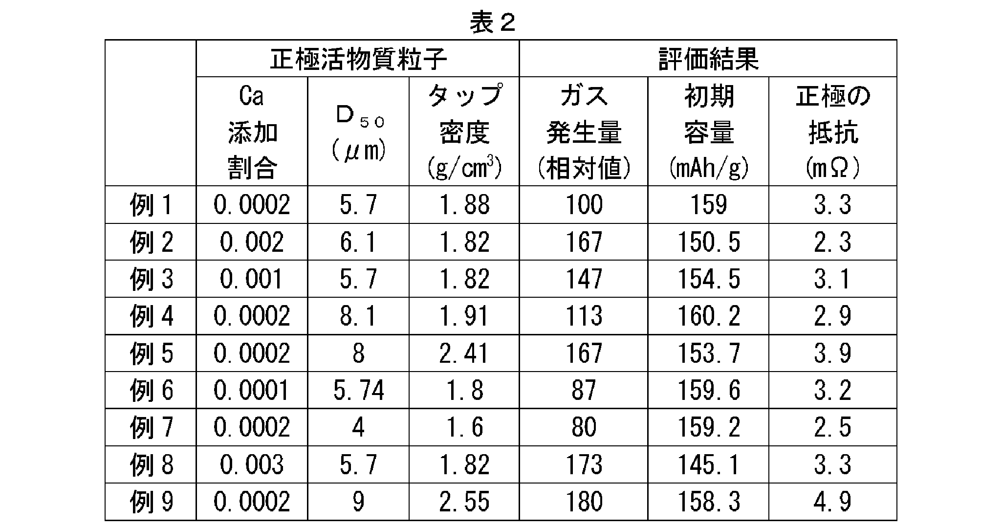
構築した電池をコンディショニング処理した。ここでは、以下の(1)~(4)を1サイクルとして、3サイクルの充放電処理を行った。
(1)1Cのレート(50mA)で4.1Vまで定電流充電(CC充電)する。
(2)5分間休止する。
(3)1Cのレート(50mA)で3.0Vまで定電流放電(CC放電)する。
(4)5分間休止する。
上記コンディショニング後の電池を、25℃の温度環境下において、以下の(1)~(4)に従って3.0Vから4.2Vの電圧範囲で充放電し、初期容量の確認を行った。
(1)電池電圧が4.2Vとなるまで1Cのレート(50mA)で定電流充電(CC充電)した後、電流が0.01Cのレート(0.5mA)になるまで定電圧充電(CV充電)を行う。
(2)1時間休止する。
(3)電池電圧が3.0Vとなるまで1Cのレート(50mA)でCC放電した後、電流が0.01Cのレート(0.5mA)になるまで定電圧放電(CV放電)を行う。
(4)5分休止する。
得られた放電容量(電流値と電圧値の積の総和)を定格容量(初期容量)とした。結果を、表2の「初期容量」の欄に示す。また、タップ密度が1.8~1.9と凡そ同等である例1~例3,例6,例8に係る電池の、正極活物質のCa添加割合と初期容量との関係を図7に示す。
次に、25℃の温度環境下において、正極の抵抗を測定した。具体的には、先ず1C(50mA)の定電流にて正負極の端子間電圧が4.1Vとなるまで充電した後、3時間定電圧充電を行って満充電状態に調整した。そして、以下の条件で交流インピーダンス測定法によって正極の抵抗を測定した。得られたCole-Coleプロット(ナイキスト・プロットともいう。)に等価回路をフィッティングさせて、正極の抵抗(mΩ)を求めた。結果を、表2の「電池抵抗(mΩ)」の欄に示す。また、Ca添加割合が0.0002と等しい例1,例4,例5,例7,例9に係る電池の正極活物質のタップ密度と電池抵抗との関係を図8に示す。
次に、25℃の温度環境下において、ガス発生量の測定を行った。具体的には、まず、過充電試験前の電池の厚み(すなわち電極体の積層方向の厚み)をロータリーキャリパーで測定した。その後、該電池に対して正負極の端子間電圧が4.1Vに到達するまで1C(50mA)でCC充電した後、3時間のCV充電を行って満充電状態に調整した。この満充電状態の電池に、積算電流が150mA(すなわち過充電状態)となるまで、さらに2C(100mA)でCC充電を行った。そして、過充電状態における電池の厚みを測定した。過充電状態の電池の厚み(cm)から、過充電試験前の電池の厚み(cm)を差し引いて、過充電時のガス発生による厚みの増加分を算出した。得られた結果を、CIDを作動させるのに必要なガス量に相当する厚みで除して、100を掛けることにより、相対値を算出した。結果を、表2の「ガス発生量」の欄に示す。この値が大きいほど過充電時のガス発生量が多いことを表している。また、ガス発生量とCa添加割合との関係を図7に、ガス発生量とタップ密度との関係を図8に、それぞれ示す。
よって、電池性能(例えばエネルギー密度や入出力密度)と過充電時の信頼性とをより高いレベルで両立させる観点から、上記一般式(I)におけるβの値は、典型的には0.0002≦β≦0.0025であり、例えば0.0002≦β<0.0025であり、好ましくは0.0002≦β≦0.002であり、特に好ましくは0.0002≦β<0.002であることがわかった。かかる結果は本発明の技術的意義を表すものである。
よって、電池性能(例えばエネルギー密度や入出力密度)と過充電時の信頼性とをより高いレベルで両立させる観点から、正極活物質のタップ密度は、典型的には1.8~2.55であり、例えば1.8~2.5であり、好ましくは1.85~2.5であり、特に好ましくは1.88~2.45であることがわかった。かかる結果は本発明の効果を表すものである。
12 正極集電体
14 正極活物質層
20 負極シート(負極)
22 負極集電体
24 負極活物質層
30 電流遮断機構(CID)
32 変形金属板(導通部材;第一部材)
33 湾曲部分
34 接続金属板(導通部材;第二部材)
35 集電リード端子
36 接合点
38 絶縁ケース
40 セパレータシート(セパレータ)
50 電池ケース
52 電池ケース本体
54 蓋体
55 安全弁
70 正極端子
72 負極端子
74 正極集電板
76 負極集電板
80 捲回電極体
100 リチウム二次電池
110 正極活物質粒子(正極活物質)
112 一次粒子
115 殻部
115a 殻部の内側面
115b 殻部の外側面
116 中空部
118 貫通孔
Claims (6)
- リチウム二次電池に用いられる正極活物質であって、以下の一般式(I):
Li1+αNixCoyMnzCaβMγO2 (I)
(ここで、-0.05≦α≦0.2、x+y+z+β+γ≒1、0.3≦x≦0.7、0.1≦y≦0.4、0.1≦z≦0.4、0.0002≦β≦0.0025、0.0002≦β+γ≦0.02であり、Mは、Na,Mg,Al,Ti,V,Cr,Zr,Nb,Mo,Hf,TaおよびWからなる群から選択される1種または2種以上の元素である。)
で表される層状構造のリチウム遷移金属酸化物からなり、
タップ密度が1.8g/cm3以上2.5g/cm3以下である粒子状の正極活物質。 - レーザー回折・光散乱法に基づいて測定される体積基準の粒度分布において、
微粒子側から累積50%に相当する平均粒径D50が5μm以上9μm以下であり、
微粒子側から累積10%に相当する粒径D10と、微粒子側から累積90%に相当する粒径D90と、前記平均粒径D50とが、以下の関係:(D90-D10)/D50≧0.7;を満たす、請求項1に記載の正極活物質。 - 前記正極活物質が、層状構造のリチウム遷移金属酸化物で構成された殻部と、その内部に形成された中空部と、を有する中空構造であり、
前記殻部の電子顕微鏡観察に基づく厚みが0.1μm以上2μm以下である、請求項1または2に記載の正極活物質。 - 前記正極活物質が前記殻部を貫通する貫通孔を有する、請求項3に記載の正極活物質。
- 前記正極活物質のX線回折に基づく結晶子径rが0.05μm以上0.2μm以下である、請求項1から4のいずれか一項に記載の正極活物質。
- 正極と負極とを含む電極体と、非水電解液と、が電池ケース内に収容されたリチウム二次電池であって、
前記電池ケースは、該電池ケースの内圧上昇時に作動する電流遮断機構を備え、
前記正極は、請求項1から5のいずれか一項に記載の正極活物質を備える、リチウム二次電池。
Priority Applications (4)
| Application Number | Priority Date | Filing Date | Title |
|---|---|---|---|
| US14/761,224 US10840509B2 (en) | 2013-01-24 | 2014-01-22 | Positive electrode active material, and lithium secondary battery using same |
| DE112014000537.1T DE112014000537B4 (de) | 2013-01-24 | 2014-01-22 | Positivelektrodenaktivmaterial und Lithium-Sekundärbatterie, die dieses verwendet |
| KR1020157022293A KR101840098B1 (ko) | 2013-01-24 | 2014-01-22 | 정극 활물질 및 상기 활물질을 사용한 리튬 이차 전지 |
| CN201480005901.8A CN104937754B (zh) | 2013-01-24 | 2014-01-22 | 正极活性物质和使用该活性物质的锂二次电池 |
Applications Claiming Priority (2)
| Application Number | Priority Date | Filing Date | Title |
|---|---|---|---|
| JP2013-011524 | 2013-01-24 | ||
| JP2013011524A JP6017978B2 (ja) | 2013-01-24 | 2013-01-24 | 正極活物質及び該活物質を用いたリチウム二次電池 |
Publications (1)
| Publication Number | Publication Date |
|---|---|
| WO2014115754A1 true WO2014115754A1 (ja) | 2014-07-31 |
Family
ID=51227545
Family Applications (1)
| Application Number | Title | Priority Date | Filing Date |
|---|---|---|---|
| PCT/JP2014/051231 Ceased WO2014115754A1 (ja) | 2013-01-24 | 2014-01-22 | 正極活物質及び該活物質を用いたリチウム二次電池 |
Country Status (6)
| Country | Link |
|---|---|
| US (1) | US10840509B2 (ja) |
| JP (1) | JP6017978B2 (ja) |
| KR (1) | KR101840098B1 (ja) |
| CN (1) | CN104937754B (ja) |
| DE (1) | DE112014000537B4 (ja) |
| WO (1) | WO2014115754A1 (ja) |
Cited By (5)
| Publication number | Priority date | Publication date | Assignee | Title |
|---|---|---|---|---|
| CN106661435A (zh) * | 2014-08-22 | 2017-05-10 | 株式会社Adeka | 抗静电剂、抗静电剂组合物、抗静电性树脂组合物及成型体 |
| US20170288223A1 (en) * | 2016-03-31 | 2017-10-05 | Honda Motor Co., Ltd. | Positive electrode active material for nonaqueous electrolyte secondary battery |
| WO2018097191A1 (ja) * | 2016-11-22 | 2018-05-31 | 住友金属鉱山株式会社 | 非水電解質二次電池用正極活物質および非水電解質二次電池 |
| EP4033569A4 (en) * | 2019-09-19 | 2023-10-18 | Sumitomo Metal Mining Co., Ltd. | Positive electrode active material for lithium ion secondary battery, and lithium ion secondary battery |
| US11804600B2 (en) | 2016-03-31 | 2023-10-31 | Nichia Corporation | Positive electrode active material for nonaqueous electrolyte secondary battery |
Families Citing this family (22)
| Publication number | Priority date | Publication date | Assignee | Title |
|---|---|---|---|---|
| US9711792B2 (en) * | 2014-03-10 | 2017-07-18 | Hitachi, Ltd. | Positive electrode active material for secondary batteries and lithium ion secondary battery using the same |
| JP6237652B2 (ja) | 2015-01-09 | 2017-11-29 | トヨタ自動車株式会社 | 非水電解質二次電池用電極およびその製造方法 |
| JP6164332B2 (ja) * | 2015-04-28 | 2017-07-19 | 日亜化学工業株式会社 | ニッケルコバルト複合水酸化物粒子とその製造方法、非水系電解質二次電池用正極活物質とその製造方法、ならびに、非水系電解質二次電池 |
| JP6394987B2 (ja) * | 2015-08-06 | 2018-09-26 | トヨタ自動車株式会社 | 非水電解液二次電池 |
| JP2017068939A (ja) * | 2015-09-29 | 2017-04-06 | 株式会社日立製作所 | リチウム二次電池 |
| JP6753050B2 (ja) * | 2015-10-26 | 2020-09-09 | 住友金属鉱山株式会社 | 非水系電解質二次電池用正極活物質、および該正極活物質を用いた非水系電解質二次電池 |
| JP6806302B2 (ja) * | 2016-02-05 | 2021-01-06 | 国立大学法人大阪大学 | 燃料電池用正極触媒 |
| JP6053982B1 (ja) * | 2016-02-22 | 2016-12-27 | Basf戸田バッテリーマテリアルズ合同会社 | 非水電解質二次電池用の正極活物質粒子及びその製造方法、並びに非水電解質二次電池 |
| JP2017188428A (ja) | 2016-03-30 | 2017-10-12 | Basf戸田バッテリーマテリアルズ合同会社 | 非水電解質二次電池用の正極活物質及びその製造方法、並びにそれを用いた非水電解質二次電池 |
| TWI633692B (zh) * | 2016-03-31 | 2018-08-21 | 烏明克公司 | 供汽車應用的鋰離子電池組 |
| KR102149721B1 (ko) | 2016-06-23 | 2020-08-31 | 히타치 긴조쿠 가부시키가이샤 | 리튬 이온 이차 전지용 정극 활물질의 제조 방법 및 리튬 이온 이차 전지용 정극 활물질, 및 리튬 이온 이차 전지 |
| JP6674631B2 (ja) * | 2016-06-23 | 2020-04-01 | トヨタ自動車株式会社 | リチウムイオン二次電池 |
| JP6949297B2 (ja) * | 2016-12-13 | 2021-10-13 | 住友金属鉱山株式会社 | 遷移金属含有複合水酸化物とその製造方法、および、非水電解質二次電池用正極活物質とその製造方法 |
| JP6691065B2 (ja) * | 2017-01-27 | 2020-04-28 | プライムアースEvエナジー株式会社 | リチウムイオン二次電池、リチウムイオン二次電池用正極活物質、及びリチウムイオン二次電池用正極活物質の製造方法 |
| CN110495035B (zh) * | 2017-03-31 | 2022-07-08 | 株式会社村田制作所 | 锂离子二次电池 |
| JP7114876B2 (ja) * | 2017-10-23 | 2022-08-09 | 住友金属鉱山株式会社 | 遷移金属複合水酸化物粒子およびその製造方法、リチウムイオン二次電池用正極活物質およびその製造方法、並びに、リチウムイオン二次電池 |
| CN112020790B (zh) * | 2018-05-07 | 2024-07-26 | 本田技研工业株式会社 | 非水电解质二次电池 |
| CN113130904B (zh) | 2020-03-11 | 2025-09-02 | 宁德新能源科技有限公司 | 正极材料及使用其的电化学装置和电子装置 |
| JP7508414B2 (ja) * | 2021-06-18 | 2024-07-01 | プライムアースEvエナジー株式会社 | 二次電池用正極の製造方法 |
| KR102650095B1 (ko) * | 2021-11-30 | 2024-03-21 | 주식회사 민테크 | 이차전지의 불량 검출 방법 및 장치 |
| JP7794696B2 (ja) * | 2022-06-14 | 2026-01-06 | トヨタ自動車株式会社 | 正極活物質粒子、ナトリウムイオン二次電池、及び、正極活物質粒子の製造方法 |
| JP2026093751A (ja) * | 2024-11-28 | 2026-06-09 | 住友金属鉱山株式会社 | リチウムニッケルマンガン複合酸化物粒子、正極板、リチウムイオン二次電池 |
Citations (7)
| Publication number | Priority date | Publication date | Assignee | Title |
|---|---|---|---|---|
| JP2005050582A (ja) * | 2003-07-30 | 2005-02-24 | Mitsubishi Chemicals Corp | リチウム二次電池用正極及びそれを用いたリチウム二次電池 |
| JP2006310181A (ja) * | 2005-04-28 | 2006-11-09 | Matsushita Electric Ind Co Ltd | 非水電解液二次電池 |
| JP2010536697A (ja) * | 2007-08-21 | 2010-12-02 | ハー.ツェー.スタルク ゲゼルシャフト ミット ベシュレンクテル ハフツング | 粉末状化合物、その製造方法並びにリチウム二次電池におけるその使用 |
| WO2011123264A2 (en) * | 2010-04-02 | 2011-10-06 | Envia System, Inc. | Doped positive electrode active materials and lithium ion secondary battery constructed therefrom |
| JP2012064573A (ja) * | 2010-08-20 | 2012-03-29 | Mitsubishi Chemicals Corp | 非水系電解液電池 |
| JP2012133888A (ja) * | 2010-12-17 | 2012-07-12 | Sumitomo Osaka Cement Co Ltd | 電極材料及びその製造方法 |
| JP2012216547A (ja) * | 2011-03-31 | 2012-11-08 | Toda Kogyo Corp | マンガンニッケル複合酸化物粒子粉末及びその製造方法、非水電解質二次電池用正極活物質粒子粉末の製造方法及び非水電解質二次電池 |
Family Cites Families (24)
| Publication number | Priority date | Publication date | Assignee | Title |
|---|---|---|---|---|
| CA2298095C (en) * | 1999-02-05 | 2005-03-01 | Ngk Insulators, Ltd. | Lithium secondary battery |
| US6623886B2 (en) | 1999-12-29 | 2003-09-23 | Kimberly-Clark Worldwide, Inc. | Nickel-rich quaternary metal oxide materials as cathodes for lithium-ion and lithium-ion polymer batteries |
| JP2001319652A (ja) * | 2000-05-11 | 2001-11-16 | Sony Corp | 正極活物質及び非水電解質電池、並びにそれらの製造方法 |
| JP4510331B2 (ja) * | 2001-06-27 | 2010-07-21 | パナソニック株式会社 | 非水電解質二次電池 |
| US7026068B2 (en) * | 2001-12-19 | 2006-04-11 | Nichia Corporation | Positive electrode active material for lithium ion secondary battery |
| JP3931706B2 (ja) | 2002-03-18 | 2007-06-20 | 三菱化学株式会社 | リチウムニッケル複合酸化物の製造方法 |
| CN100527520C (zh) | 2005-06-14 | 2009-08-12 | 松下电器产业株式会社 | 非水电解质二次电池 |
| JP5153060B2 (ja) | 2005-06-16 | 2013-02-27 | パナソニック株式会社 | リチウムイオン二次電池 |
| JP5017806B2 (ja) | 2005-06-20 | 2012-09-05 | ソニー株式会社 | 二次電池用正極活物質およびその製造方法、並びに二次電池 |
| JP5260821B2 (ja) * | 2005-07-11 | 2013-08-14 | パナソニック株式会社 | リチウムイオン二次電池 |
| JP5143568B2 (ja) * | 2005-12-20 | 2013-02-13 | パナソニック株式会社 | 非水電解質二次電池 |
| JP2008053054A (ja) | 2006-08-24 | 2008-03-06 | Sony Corp | 電池 |
| KR101234965B1 (ko) | 2007-11-06 | 2013-02-20 | 파나소닉 주식회사 | 비수전해질 이차전지용 양극 활물질 및 그것을 이용한 비수전해질 이차전지 |
| WO2010002089A1 (en) * | 2008-06-30 | 2010-01-07 | Lg Chem, Ltd. | Cylindrical lithium secondary battery |
| JP2012504932A (ja) * | 2008-10-02 | 2012-02-23 | レイデン エナジー インコーポレイテッド | バッテリ用電子電流遮断デバイス |
| EP2357154B1 (en) | 2008-12-02 | 2014-04-23 | Mitsubishi Chemical Corporation | Production process of a nonaqueous electrolytic solution comprising a production process of difluorophosphate |
| US8465873B2 (en) * | 2008-12-11 | 2013-06-18 | Envia Systems, Inc. | Positive electrode materials for high discharge capacity lithium ion batteries |
| JP5638232B2 (ja) | 2009-12-02 | 2014-12-10 | 住友金属鉱山株式会社 | 非水系電解質二次電池正極活物質用ニッケルコバルトマンガン複合水酸化物粒子とその製造方法、非水系電解質二次電池用正極活物質とその製造方法、および非水系電解質二次電池 |
| EP2421077B1 (en) | 2010-08-17 | 2013-10-23 | Umicore | Positive electrode materials combining high safety and high power in a Li rechargeable battery |
| US9553310B2 (en) * | 2010-10-15 | 2017-01-24 | Toyota Jidosha Kabushiki Kaisha | Secondary battery |
| JP5389772B2 (ja) | 2010-12-07 | 2014-01-15 | 株式会社日立製作所 | リチウム二次電池 |
| WO2012131881A1 (ja) | 2011-03-28 | 2012-10-04 | 住友金属鉱山株式会社 | ニッケルマンガン複合水酸化物粒子とその製造方法、非水系電解質二次電池用正極活物質とその製造方法、および非水系電解質二次電池 |
| WO2012153379A1 (ja) | 2011-05-06 | 2012-11-15 | トヨタ自動車株式会社 | リチウムイオン二次電池 |
| JP4894969B1 (ja) * | 2011-06-07 | 2012-03-14 | 住友金属鉱山株式会社 | ニッケルマンガン複合水酸化物粒子とその製造方法、非水系電解質二次電池用正極活物質とその製造方法、ならびに、非水系電解質二次電池 |
-
2013
- 2013-01-24 JP JP2013011524A patent/JP6017978B2/ja active Active
-
2014
- 2014-01-22 CN CN201480005901.8A patent/CN104937754B/zh active Active
- 2014-01-22 WO PCT/JP2014/051231 patent/WO2014115754A1/ja not_active Ceased
- 2014-01-22 DE DE112014000537.1T patent/DE112014000537B4/de active Active
- 2014-01-22 US US14/761,224 patent/US10840509B2/en active Active
- 2014-01-22 KR KR1020157022293A patent/KR101840098B1/ko active Active
Patent Citations (7)
| Publication number | Priority date | Publication date | Assignee | Title |
|---|---|---|---|---|
| JP2005050582A (ja) * | 2003-07-30 | 2005-02-24 | Mitsubishi Chemicals Corp | リチウム二次電池用正極及びそれを用いたリチウム二次電池 |
| JP2006310181A (ja) * | 2005-04-28 | 2006-11-09 | Matsushita Electric Ind Co Ltd | 非水電解液二次電池 |
| JP2010536697A (ja) * | 2007-08-21 | 2010-12-02 | ハー.ツェー.スタルク ゲゼルシャフト ミット ベシュレンクテル ハフツング | 粉末状化合物、その製造方法並びにリチウム二次電池におけるその使用 |
| WO2011123264A2 (en) * | 2010-04-02 | 2011-10-06 | Envia System, Inc. | Doped positive electrode active materials and lithium ion secondary battery constructed therefrom |
| JP2012064573A (ja) * | 2010-08-20 | 2012-03-29 | Mitsubishi Chemicals Corp | 非水系電解液電池 |
| JP2012133888A (ja) * | 2010-12-17 | 2012-07-12 | Sumitomo Osaka Cement Co Ltd | 電極材料及びその製造方法 |
| JP2012216547A (ja) * | 2011-03-31 | 2012-11-08 | Toda Kogyo Corp | マンガンニッケル複合酸化物粒子粉末及びその製造方法、非水電解質二次電池用正極活物質粒子粉末の製造方法及び非水電解質二次電池 |
Cited By (11)
| Publication number | Priority date | Publication date | Assignee | Title |
|---|---|---|---|---|
| CN106661435A (zh) * | 2014-08-22 | 2017-05-10 | 株式会社Adeka | 抗静电剂、抗静电剂组合物、抗静电性树脂组合物及成型体 |
| CN106661435B (zh) * | 2014-08-22 | 2018-09-11 | 株式会社Adeka | 抗静电剂、抗静电剂组合物、抗静电性树脂组合物及成型体 |
| US20170288223A1 (en) * | 2016-03-31 | 2017-10-05 | Honda Motor Co., Ltd. | Positive electrode active material for nonaqueous electrolyte secondary battery |
| US10622629B2 (en) * | 2016-03-31 | 2020-04-14 | Honda Motor Co., Ltd. | Positive electrode active material for nonaqueous electrolyte secondary battery |
| US11380892B2 (en) | 2016-03-31 | 2022-07-05 | Nichia Corporation | Positive electrode active material for nonaqueous electrolyte secondary battery |
| US11804600B2 (en) | 2016-03-31 | 2023-10-31 | Nichia Corporation | Positive electrode active material for nonaqueous electrolyte secondary battery |
| US12218351B2 (en) | 2016-03-31 | 2025-02-04 | Honda Motor Co., Ltd. | Positive electrode active material for nonaqueous electrolyte secondary battery |
| WO2018097191A1 (ja) * | 2016-11-22 | 2018-05-31 | 住友金属鉱山株式会社 | 非水電解質二次電池用正極活物質および非水電解質二次電池 |
| JPWO2018097191A1 (ja) * | 2016-11-22 | 2019-06-24 | 住友金属鉱山株式会社 | 非水電解質二次電池用正極活物質および非水電解質二次電池 |
| EP4033569A4 (en) * | 2019-09-19 | 2023-10-18 | Sumitomo Metal Mining Co., Ltd. | Positive electrode active material for lithium ion secondary battery, and lithium ion secondary battery |
| US12562383B2 (en) | 2019-09-19 | 2026-02-24 | Sumitomo Metal Mining Co., Ltd. | Positive electrode active material for lithium ion secondary battery and lithium ion secondary battery |
Also Published As
| Publication number | Publication date |
|---|---|
| KR101840098B1 (ko) | 2018-03-19 |
| CN104937754B (zh) | 2018-07-03 |
| US10840509B2 (en) | 2020-11-17 |
| DE112014000537T5 (de) | 2015-11-05 |
| JP2014143108A (ja) | 2014-08-07 |
| US20160006030A1 (en) | 2016-01-07 |
| CN104937754A (zh) | 2015-09-23 |
| JP6017978B2 (ja) | 2016-11-02 |
| KR20150108397A (ko) | 2015-09-25 |
| DE112014000537B4 (de) | 2023-11-23 |
Similar Documents
| Publication | Publication Date | Title |
|---|---|---|
| JP6017978B2 (ja) | 正極活物質及び該活物質を用いたリチウム二次電池 | |
| JP5896218B2 (ja) | 密閉型非水電解質二次電池 | |
| CN101414676B (zh) | 负极和电池 | |
| CN102388490B (zh) | 锂二次电池 | |
| JP5741899B2 (ja) | 二次電池 | |
| JP5904373B2 (ja) | 非水電解質二次電池 | |
| JP5664932B2 (ja) | 二次電池 | |
| JP6016018B2 (ja) | 非水電解液二次電池 | |
| JPWO2015111710A1 (ja) | 非水二次電池 | |
| CN107078280A (zh) | 非水电解质二次电池 | |
| JP5517007B2 (ja) | リチウムイオン二次電池 | |
| JP2013235653A (ja) | 密閉型非水電解質二次電池 | |
| JP5962956B2 (ja) | リチウム二次電池 | |
| JP5920631B2 (ja) | 非水電解質二次電池 | |
| JP6453203B2 (ja) | 負極活物質、負極電極、リチウムイオン二次電池、非水電解質二次電池用負極材の製造方法及びリチウムイオン二次電池の製造方法 | |
| JP5855737B2 (ja) | リチウムイオン電池 | |
| JP5835617B2 (ja) | 密閉型リチウム二次電池 | |
| JPWO2020017581A1 (ja) | 非水電解質蓄電素子、及び蓄電装置 | |
| JP7288479B2 (ja) | 非水電解質二次電池 | |
| JP2013157219A (ja) | 非水電解質二次電池 | |
| JP5904366B2 (ja) | 非水電解質二次電池およびその製造方法 | |
| JP2016139549A (ja) | リチウムイオン電池 | |
| WO2016194589A1 (ja) | リチウムイオン二次電池 | |
| JP6016015B2 (ja) | 非水電解質二次電池 | |
| CN118867351A (zh) | 锂离子二次电池 |
Legal Events
| Date | Code | Title | Description |
|---|---|---|---|
| 121 | Ep: the epo has been informed by wipo that ep was designated in this application |
Ref document number: 14743131 Country of ref document: EP Kind code of ref document: A1 |
|
| WWE | Wipo information: entry into national phase |
Ref document number: 14761224 Country of ref document: US |
|
| WWE | Wipo information: entry into national phase |
Ref document number: 1120140005371 Country of ref document: DE Ref document number: 112014000537 Country of ref document: DE |
|
| ENP | Entry into the national phase |
Ref document number: 20157022293 Country of ref document: KR Kind code of ref document: A |
|
| 122 | Ep: pct application non-entry in european phase |
Ref document number: 14743131 Country of ref document: EP Kind code of ref document: A1 |