WO2014010351A1 - 空気入りタイヤ - Google Patents
空気入りタイヤ Download PDFInfo
- Publication number
- WO2014010351A1 WO2014010351A1 PCT/JP2013/065846 JP2013065846W WO2014010351A1 WO 2014010351 A1 WO2014010351 A1 WO 2014010351A1 JP 2013065846 W JP2013065846 W JP 2013065846W WO 2014010351 A1 WO2014010351 A1 WO 2014010351A1
- Authority
- WO
- WIPO (PCT)
- Prior art keywords
- tire
- belt
- groove
- circumferential
- layer
- Prior art date
- Legal status (The legal status is an assumption and is not a legal conclusion. Google has not performed a legal analysis and makes no representation as to the accuracy of the status listed.)
- Ceased
Links
Images









Classifications
-
- B—PERFORMING OPERATIONS; TRANSPORTING
- B60—VEHICLES IN GENERAL
- B60C—VEHICLE TYRES; TYRE INFLATION; TYRE CHANGING; CONNECTING VALVES TO INFLATABLE ELASTIC BODIES IN GENERAL; DEVICES OR ARRANGEMENTS RELATED TO TYRES
- B60C9/00—Reinforcements or ply arrangement of pneumatic tyres
- B60C9/18—Structure or arrangement of belts or breakers, crown-reinforcing or cushioning layers
- B60C9/20—Structure or arrangement of belts or breakers, crown-reinforcing or cushioning layers built-up from rubberised plies each having all cords arranged substantially parallel
-
- B—PERFORMING OPERATIONS; TRANSPORTING
- B60—VEHICLES IN GENERAL
- B60C—VEHICLE TYRES; TYRE INFLATION; TYRE CHANGING; CONNECTING VALVES TO INFLATABLE ELASTIC BODIES IN GENERAL; DEVICES OR ARRANGEMENTS RELATED TO TYRES
- B60C9/00—Reinforcements or ply arrangement of pneumatic tyres
- B60C9/18—Structure or arrangement of belts or breakers, crown-reinforcing or cushioning layers
- B60C9/28—Structure or arrangement of belts or breakers, crown-reinforcing or cushioning layers characterised by the belt or breaker dimensions or curvature relative to carcass
-
- B—PERFORMING OPERATIONS; TRANSPORTING
- B60—VEHICLES IN GENERAL
- B60C—VEHICLE TYRES; TYRE INFLATION; TYRE CHANGING; CONNECTING VALVES TO INFLATABLE ELASTIC BODIES IN GENERAL; DEVICES OR ARRANGEMENTS RELATED TO TYRES
- B60C11/00—Tyre tread bands; Tread patterns; Anti-skid inserts
- B60C11/0083—Tyre tread bands; Tread patterns; Anti-skid inserts characterised by the curvature of the tyre tread
-
- B—PERFORMING OPERATIONS; TRANSPORTING
- B60—VEHICLES IN GENERAL
- B60C—VEHICLE TYRES; TYRE INFLATION; TYRE CHANGING; CONNECTING VALVES TO INFLATABLE ELASTIC BODIES IN GENERAL; DEVICES OR ARRANGEMENTS RELATED TO TYRES
- B60C11/00—Tyre tread bands; Tread patterns; Anti-skid inserts
- B60C11/03—Tread patterns
-
- B—PERFORMING OPERATIONS; TRANSPORTING
- B60—VEHICLES IN GENERAL
- B60C—VEHICLE TYRES; TYRE INFLATION; TYRE CHANGING; CONNECTING VALVES TO INFLATABLE ELASTIC BODIES IN GENERAL; DEVICES OR ARRANGEMENTS RELATED TO TYRES
- B60C11/00—Tyre tread bands; Tread patterns; Anti-skid inserts
- B60C11/03—Tread patterns
- B60C11/0306—Patterns comprising block rows or discontinuous ribs
-
- B—PERFORMING OPERATIONS; TRANSPORTING
- B60—VEHICLES IN GENERAL
- B60C—VEHICLE TYRES; TYRE INFLATION; TYRE CHANGING; CONNECTING VALVES TO INFLATABLE ELASTIC BODIES IN GENERAL; DEVICES OR ARRANGEMENTS RELATED TO TYRES
- B60C11/00—Tyre tread bands; Tread patterns; Anti-skid inserts
- B60C11/03—Tread patterns
- B60C11/13—Tread patterns characterised by the groove cross-section, e.g. for buttressing or preventing stone-trapping
- B60C11/1376—Three dimensional block surfaces departing from the enveloping tread contour
- B60C11/1392—Three dimensional block surfaces departing from the enveloping tread contour with chamfered block edges
-
- B—PERFORMING OPERATIONS; TRANSPORTING
- B60—VEHICLES IN GENERAL
- B60C—VEHICLE TYRES; TYRE INFLATION; TYRE CHANGING; CONNECTING VALVES TO INFLATABLE ELASTIC BODIES IN GENERAL; DEVICES OR ARRANGEMENTS RELATED TO TYRES
- B60C3/00—Tyres characterised by the transverse section
- B60C3/04—Tyres characterised by the transverse section characterised by the relative dimensions of the section, e.g. low profile
-
- B—PERFORMING OPERATIONS; TRANSPORTING
- B60—VEHICLES IN GENERAL
- B60C—VEHICLE TYRES; TYRE INFLATION; TYRE CHANGING; CONNECTING VALVES TO INFLATABLE ELASTIC BODIES IN GENERAL; DEVICES OR ARRANGEMENTS RELATED TO TYRES
- B60C9/00—Reinforcements or ply arrangement of pneumatic tyres
- B60C9/18—Structure or arrangement of belts or breakers, crown-reinforcing or cushioning layers
-
- B—PERFORMING OPERATIONS; TRANSPORTING
- B60—VEHICLES IN GENERAL
- B60C—VEHICLE TYRES; TYRE INFLATION; TYRE CHANGING; CONNECTING VALVES TO INFLATABLE ELASTIC BODIES IN GENERAL; DEVICES OR ARRANGEMENTS RELATED TO TYRES
- B60C9/00—Reinforcements or ply arrangement of pneumatic tyres
- B60C9/18—Structure or arrangement of belts or breakers, crown-reinforcing or cushioning layers
- B60C9/1835—Rubber strips or cushions at the belt edges
- B60C9/185—Rubber strips or cushions at the belt edges between adjacent or radially below the belt plies
-
- B—PERFORMING OPERATIONS; TRANSPORTING
- B60—VEHICLES IN GENERAL
- B60C—VEHICLE TYRES; TYRE INFLATION; TYRE CHANGING; CONNECTING VALVES TO INFLATABLE ELASTIC BODIES IN GENERAL; DEVICES OR ARRANGEMENTS RELATED TO TYRES
- B60C9/00—Reinforcements or ply arrangement of pneumatic tyres
- B60C9/18—Structure or arrangement of belts or breakers, crown-reinforcing or cushioning layers
- B60C9/20—Structure or arrangement of belts or breakers, crown-reinforcing or cushioning layers built-up from rubberised plies each having all cords arranged substantially parallel
- B60C9/2003—Structure or arrangement of belts or breakers, crown-reinforcing or cushioning layers built-up from rubberised plies each having all cords arranged substantially parallel characterised by the materials of the belt cords
-
- B—PERFORMING OPERATIONS; TRANSPORTING
- B60—VEHICLES IN GENERAL
- B60C—VEHICLE TYRES; TYRE INFLATION; TYRE CHANGING; CONNECTING VALVES TO INFLATABLE ELASTIC BODIES IN GENERAL; DEVICES OR ARRANGEMENTS RELATED TO TYRES
- B60C9/00—Reinforcements or ply arrangement of pneumatic tyres
- B60C9/18—Structure or arrangement of belts or breakers, crown-reinforcing or cushioning layers
- B60C9/20—Structure or arrangement of belts or breakers, crown-reinforcing or cushioning layers built-up from rubberised plies each having all cords arranged substantially parallel
- B60C9/2003—Structure or arrangement of belts or breakers, crown-reinforcing or cushioning layers built-up from rubberised plies each having all cords arranged substantially parallel characterised by the materials of the belt cords
- B60C9/2006—Structure or arrangement of belts or breakers, crown-reinforcing or cushioning layers built-up from rubberised plies each having all cords arranged substantially parallel characterised by the materials of the belt cords consisting of steel cord plies only
-
- B—PERFORMING OPERATIONS; TRANSPORTING
- B60—VEHICLES IN GENERAL
- B60C—VEHICLE TYRES; TYRE INFLATION; TYRE CHANGING; CONNECTING VALVES TO INFLATABLE ELASTIC BODIES IN GENERAL; DEVICES OR ARRANGEMENTS RELATED TO TYRES
- B60C9/00—Reinforcements or ply arrangement of pneumatic tyres
- B60C9/18—Structure or arrangement of belts or breakers, crown-reinforcing or cushioning layers
- B60C9/20—Structure or arrangement of belts or breakers, crown-reinforcing or cushioning layers built-up from rubberised plies each having all cords arranged substantially parallel
- B60C9/22—Structure or arrangement of belts or breakers, crown-reinforcing or cushioning layers built-up from rubberised plies each having all cords arranged substantially parallel the plies being arranged with all cords disposed along the circumference of the tyre
-
- B—PERFORMING OPERATIONS; TRANSPORTING
- B60—VEHICLES IN GENERAL
- B60C—VEHICLE TYRES; TYRE INFLATION; TYRE CHANGING; CONNECTING VALVES TO INFLATABLE ELASTIC BODIES IN GENERAL; DEVICES OR ARRANGEMENTS RELATED TO TYRES
- B60C9/00—Reinforcements or ply arrangement of pneumatic tyres
- B60C9/18—Structure or arrangement of belts or breakers, crown-reinforcing or cushioning layers
- B60C9/20—Structure or arrangement of belts or breakers, crown-reinforcing or cushioning layers built-up from rubberised plies each having all cords arranged substantially parallel
- B60C2009/2012—Structure or arrangement of belts or breakers, crown-reinforcing or cushioning layers built-up from rubberised plies each having all cords arranged substantially parallel with particular configuration of the belt cords in the respective belt layers
-
- B—PERFORMING OPERATIONS; TRANSPORTING
- B60—VEHICLES IN GENERAL
- B60C—VEHICLE TYRES; TYRE INFLATION; TYRE CHANGING; CONNECTING VALVES TO INFLATABLE ELASTIC BODIES IN GENERAL; DEVICES OR ARRANGEMENTS RELATED TO TYRES
- B60C9/00—Reinforcements or ply arrangement of pneumatic tyres
- B60C9/18—Structure or arrangement of belts or breakers, crown-reinforcing or cushioning layers
- B60C9/20—Structure or arrangement of belts or breakers, crown-reinforcing or cushioning layers built-up from rubberised plies each having all cords arranged substantially parallel
- B60C2009/2012—Structure or arrangement of belts or breakers, crown-reinforcing or cushioning layers built-up from rubberised plies each having all cords arranged substantially parallel with particular configuration of the belt cords in the respective belt layers
- B60C2009/2016—Structure or arrangement of belts or breakers, crown-reinforcing or cushioning layers built-up from rubberised plies each having all cords arranged substantially parallel with particular configuration of the belt cords in the respective belt layers comprising cords at an angle of 10 to 30 degrees to the circumferential direction
-
- B—PERFORMING OPERATIONS; TRANSPORTING
- B60—VEHICLES IN GENERAL
- B60C—VEHICLE TYRES; TYRE INFLATION; TYRE CHANGING; CONNECTING VALVES TO INFLATABLE ELASTIC BODIES IN GENERAL; DEVICES OR ARRANGEMENTS RELATED TO TYRES
- B60C9/00—Reinforcements or ply arrangement of pneumatic tyres
- B60C9/18—Structure or arrangement of belts or breakers, crown-reinforcing or cushioning layers
- B60C9/20—Structure or arrangement of belts or breakers, crown-reinforcing or cushioning layers built-up from rubberised plies each having all cords arranged substantially parallel
- B60C2009/2012—Structure or arrangement of belts or breakers, crown-reinforcing or cushioning layers built-up from rubberised plies each having all cords arranged substantially parallel with particular configuration of the belt cords in the respective belt layers
- B60C2009/2019—Structure or arrangement of belts or breakers, crown-reinforcing or cushioning layers built-up from rubberised plies each having all cords arranged substantially parallel with particular configuration of the belt cords in the respective belt layers comprising cords at an angle of 30 to 60 degrees to the circumferential direction
-
- B—PERFORMING OPERATIONS; TRANSPORTING
- B60—VEHICLES IN GENERAL
- B60C—VEHICLE TYRES; TYRE INFLATION; TYRE CHANGING; CONNECTING VALVES TO INFLATABLE ELASTIC BODIES IN GENERAL; DEVICES OR ARRANGEMENTS RELATED TO TYRES
- B60C9/00—Reinforcements or ply arrangement of pneumatic tyres
- B60C9/18—Structure or arrangement of belts or breakers, crown-reinforcing or cushioning layers
- B60C9/20—Structure or arrangement of belts or breakers, crown-reinforcing or cushioning layers built-up from rubberised plies each having all cords arranged substantially parallel
- B60C2009/2012—Structure or arrangement of belts or breakers, crown-reinforcing or cushioning layers built-up from rubberised plies each having all cords arranged substantially parallel with particular configuration of the belt cords in the respective belt layers
- B60C2009/2022—Structure or arrangement of belts or breakers, crown-reinforcing or cushioning layers built-up from rubberised plies each having all cords arranged substantially parallel with particular configuration of the belt cords in the respective belt layers comprising cords at an angle of 60 to 90 degrees to the circumferential direction
-
- B—PERFORMING OPERATIONS; TRANSPORTING
- B60—VEHICLES IN GENERAL
- B60C—VEHICLE TYRES; TYRE INFLATION; TYRE CHANGING; CONNECTING VALVES TO INFLATABLE ELASTIC BODIES IN GENERAL; DEVICES OR ARRANGEMENTS RELATED TO TYRES
- B60C9/00—Reinforcements or ply arrangement of pneumatic tyres
- B60C9/18—Structure or arrangement of belts or breakers, crown-reinforcing or cushioning layers
- B60C9/20—Structure or arrangement of belts or breakers, crown-reinforcing or cushioning layers built-up from rubberised plies each having all cords arranged substantially parallel
- B60C2009/2041—Structure or arrangement of belts or breakers, crown-reinforcing or cushioning layers built-up from rubberised plies each having all cords arranged substantially parallel with an interrupted belt ply, e.g. using two or more portions of the same ply
-
- B—PERFORMING OPERATIONS; TRANSPORTING
- B60—VEHICLES IN GENERAL
- B60C—VEHICLE TYRES; TYRE INFLATION; TYRE CHANGING; CONNECTING VALVES TO INFLATABLE ELASTIC BODIES IN GENERAL; DEVICES OR ARRANGEMENTS RELATED TO TYRES
- B60C9/00—Reinforcements or ply arrangement of pneumatic tyres
- B60C9/18—Structure or arrangement of belts or breakers, crown-reinforcing or cushioning layers
- B60C9/20—Structure or arrangement of belts or breakers, crown-reinforcing or cushioning layers built-up from rubberised plies each having all cords arranged substantially parallel
- B60C2009/2061—Physical properties or dimensions of the belt coating rubber
-
- B—PERFORMING OPERATIONS; TRANSPORTING
- B60—VEHICLES IN GENERAL
- B60C—VEHICLE TYRES; TYRE INFLATION; TYRE CHANGING; CONNECTING VALVES TO INFLATABLE ELASTIC BODIES IN GENERAL; DEVICES OR ARRANGEMENTS RELATED TO TYRES
- B60C9/00—Reinforcements or ply arrangement of pneumatic tyres
- B60C9/18—Structure or arrangement of belts or breakers, crown-reinforcing or cushioning layers
- B60C9/20—Structure or arrangement of belts or breakers, crown-reinforcing or cushioning layers built-up from rubberised plies each having all cords arranged substantially parallel
- B60C2009/2061—Physical properties or dimensions of the belt coating rubber
- B60C2009/2064—Modulus; Hardness; Loss modulus or "tangens delta"
-
- B—PERFORMING OPERATIONS; TRANSPORTING
- B60—VEHICLES IN GENERAL
- B60C—VEHICLE TYRES; TYRE INFLATION; TYRE CHANGING; CONNECTING VALVES TO INFLATABLE ELASTIC BODIES IN GENERAL; DEVICES OR ARRANGEMENTS RELATED TO TYRES
- B60C9/00—Reinforcements or ply arrangement of pneumatic tyres
- B60C9/18—Structure or arrangement of belts or breakers, crown-reinforcing or cushioning layers
- B60C9/20—Structure or arrangement of belts or breakers, crown-reinforcing or cushioning layers built-up from rubberised plies each having all cords arranged substantially parallel
- B60C2009/2074—Physical properties or dimension of the belt cord
- B60C2009/2077—Diameters of the cords; Linear density thereof
-
- B—PERFORMING OPERATIONS; TRANSPORTING
- B60—VEHICLES IN GENERAL
- B60C—VEHICLE TYRES; TYRE INFLATION; TYRE CHANGING; CONNECTING VALVES TO INFLATABLE ELASTIC BODIES IN GENERAL; DEVICES OR ARRANGEMENTS RELATED TO TYRES
- B60C9/00—Reinforcements or ply arrangement of pneumatic tyres
- B60C9/18—Structure or arrangement of belts or breakers, crown-reinforcing or cushioning layers
- B60C9/20—Structure or arrangement of belts or breakers, crown-reinforcing or cushioning layers built-up from rubberised plies each having all cords arranged substantially parallel
- B60C2009/2074—Physical properties or dimension of the belt cord
- B60C2009/2083—Density in width direction
-
- B—PERFORMING OPERATIONS; TRANSPORTING
- B60—VEHICLES IN GENERAL
- B60C—VEHICLE TYRES; TYRE INFLATION; TYRE CHANGING; CONNECTING VALVES TO INFLATABLE ELASTIC BODIES IN GENERAL; DEVICES OR ARRANGEMENTS RELATED TO TYRES
- B60C9/00—Reinforcements or ply arrangement of pneumatic tyres
- B60C9/18—Structure or arrangement of belts or breakers, crown-reinforcing or cushioning layers
- B60C9/28—Structure or arrangement of belts or breakers, crown-reinforcing or cushioning layers characterised by the belt or breaker dimensions or curvature relative to carcass
- B60C2009/283—Structure or arrangement of belts or breakers, crown-reinforcing or cushioning layers characterised by the belt or breaker dimensions or curvature relative to carcass characterised by belt curvature
-
- Y—GENERAL TAGGING OF NEW TECHNOLOGICAL DEVELOPMENTS; GENERAL TAGGING OF CROSS-SECTIONAL TECHNOLOGIES SPANNING OVER SEVERAL SECTIONS OF THE IPC; TECHNICAL SUBJECTS COVERED BY FORMER USPC CROSS-REFERENCE ART COLLECTIONS [XRACs] AND DIGESTS
- Y10—TECHNICAL SUBJECTS COVERED BY FORMER USPC
- Y10T—TECHNICAL SUBJECTS COVERED BY FORMER US CLASSIFICATION
- Y10T152/00—Resilient tires and wheels
- Y10T152/10—Tires, resilient
- Y10T152/10495—Pneumatic tire or inner tube
- Y10T152/10765—Characterized by belt or breaker structure
- Y10T152/10801—Structure made up of two or more sets of plies wherein the reinforcing cords in one set lie in a different angular position relative to those in other sets
Definitions
- the present invention relates to a pneumatic tire, and more particularly to a pneumatic tire capable of improving the yield of a base tire used for a retread tire.
- the retreaded tire is a tire that is reused by replacing the tread rubber of a tire whose remaining groove has reached the end of its life, and is manufactured by two methods, a pre-curing method and a remolding method.
- Precured retreaded tires are manufactured by cutting off the tread rubber of a used tire by buffing to form a base tire, and then bonding a vulcanized precured tread with a tread pattern when new to the base tire.
- the Remolded retreaded tires are obtained by cutting off the tread rubber of a used tire by buffing to form a base tire, winding an unvulcanized tread rubber around the base tire, and adding it using a molding die having a tread pattern. Manufactured by sulfur molding.
- the present invention has been made in view of the above, and an object thereof is to provide a pneumatic tire that can improve the yield of a base tire used for a retread tire.
- a pneumatic tire according to the present invention includes a carcass layer, a belt layer disposed on the outer side in the tire radial direction of the carcass layer, and a tread rubber disposed on the outer side in the tire radial direction of the belt layer.
- a pneumatic tire including at least three circumferential main grooves extending in the tire circumferential direction and a plurality of land portions defined by the circumferential main grooves, the belt layer An inner diameter side cross belt and an outer diameter side cross belt having belt angles of 46 [deg] or more and 80 [deg] or less in absolute value with respect to the tire circumferential direction, and belt angles having mutually different signs, A circumferential reinforcing layer having a belt angle within a range of ⁇ 5 [deg] with respect to the direction and disposed between the inner diameter side crossing belt and the outer diameter side crossing belt, and a tie
- the distance Gcc from the tread profile to the inner circumferential surface the tire at the equatorial plane, the distance Gsh from the tread end to the inner circumferential surface the tire is characterized by having a relation of 1.10 ⁇ Gsh / Gcc.
- the pair of intersecting belts functions as a high-angle belt, and the rigidity in the tire width direction is ensured.
- the circumferential reinforcing layer and the additional belt function as a low-angle belt, and the rigidity in the tire circumferential direction is ensured.
- the rigidity balance between the tire circumferential direction and the tire width direction is optimized, and deformation of the tread portion over time is suppressed.
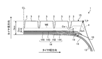
- FIG. 1 is a sectional view in the tire meridian direction showing a pneumatic tire according to an embodiment of the present invention.
- FIG. 2 is an explanatory view showing a belt layer of the pneumatic tire shown in FIG.
- FIG. 3 is an explanatory view showing a belt layer of the pneumatic tire shown in FIG. 1.
- FIG. 4 is an explanatory view showing the operation of the pneumatic tire shown in FIG.
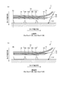
- FIG. 5 is an enlarged cross-sectional view illustrating a shoulder portion of the pneumatic tire illustrated in FIG. 1.
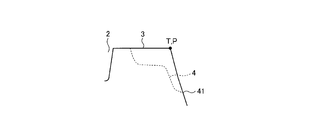
- FIG. 6 is an enlarged cross-sectional view illustrating a shoulder portion of the pneumatic tire illustrated in FIG. 1.
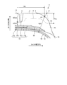
- FIG. 7 is an enlarged cross-sectional view illustrating a shoulder portion of the pneumatic tire illustrated in FIG. 1.
- FIG. 1 is a sectional view in the tire meridian direction showing a pneumatic tire according to an embodiment of the present invention.
- FIG. 2 is an explanatory view showing a belt layer of the pneumatic tire shown in FIG
- FIG. 8 is an enlarged cross-sectional view illustrating a shoulder portion of the pneumatic tire illustrated in FIG. 1.
- FIG. 9 is an enlarged cross-sectional view illustrating a shoulder portion of the pneumatic tire illustrated in FIG. 1.
- FIG. 10 is an explanatory view showing a modified example of the pneumatic tire shown in FIG. 1.
- FIG. 11 is an explanatory view showing a modified example of the pneumatic tire shown in FIG. 1.
- FIG. 12 is an explanatory diagram illustrating a modification of the pneumatic tire depicted in FIG. 1.
- FIG. 13 is an explanatory view illustrating a modified example of the pneumatic tire depicted in FIG. 1.
- FIG. 14 is an explanatory view showing a modified example of the pneumatic tire depicted in FIG. 1.
- FIG. 10 is an explanatory view showing a modified example of the pneumatic tire shown in FIG. 1.
- FIG. 11 is an explanatory view showing a modified example of the pneumatic tire shown in FIG. 1.
- FIG. 12 is an
- FIG. 15 is an explanatory view showing a modified example of the pneumatic tire shown in FIG. 1.
- FIG. 16 is a chart showing the results of the performance test of the pneumatic tire according to the embodiment of the present invention.
- FIG. 17 is a chart showing the results of the performance test of the pneumatic tire according to the embodiment of the present invention.
- FIG. 1 is a sectional view in the tire meridian direction showing a pneumatic tire according to an embodiment of the present invention.
- FIG. 1 shows a heavy-duty radial tire mounted on a truck, a bus, etc. for long-distance transportation.
- Reference sign CL is a tire equator plane.
- the tread end P and the tire ground contact end T coincide.
- the circumferential reinforcing layer 145 is hatched.
- the pneumatic tire 1 includes a pair of bead cores 11, 11, a pair of bead fillers 12, 12, a carcass layer 13, a belt layer 14, a tread rubber 15, and a pair of sidewall rubbers 16, 16. (See FIG. 1).
- the pair of bead cores 11 and 11 has an annular structure and constitutes the core of the left and right bead portions.
- the pair of bead fillers 12 and 12 includes a lower filler 121 and an upper filler 122, which are disposed on the tire radial direction outer periphery of the pair of bead cores 11 and 11, respectively, to reinforce the bead portion.
- the carcass layer 13 is bridged in a toroidal shape between the left and right bead cores 11 and 11 to form a tire skeleton. Further, both ends of the carcass layer 13 are wound and locked from the inner side in the tire width direction to the outer side in the tire width direction so as to wrap the bead core 11 and the bead filler 12.
- the carcass layer 13 is formed by coating a plurality of carcass cords made of steel or an organic fiber material (for example, nylon, polyester, rayon, etc.) with a coating rubber and rolling them, and has an absolute value of 85 [deg] or more and 95. [Deg] The following carcass angle (inclination angle in the fiber direction of the carcass cord with respect to the tire circumferential direction).
- the belt layer 14 is formed by laminating a plurality of belt plies 142, 143, 144, and 145, and is arranged around the outer periphery of the carcass layer 13. A specific configuration of the belt layer 14 will be described later.
- the tread rubber 15 is disposed on the outer circumference in the tire radial direction of the carcass layer 13 and the belt layer 14 to constitute a tread portion of the tire.
- the pair of side wall rubbers 16 and 16 are respectively arranged on the outer side in the tire width direction of the carcass layer 13 to constitute left and right side wall portions.
- the pneumatic tire 1 includes seven circumferential main grooves 2 extending in the tire circumferential direction and eight land portions 3 that are partitioned by these circumferential main grooves 2. I have.
- each land portion 3 is a row of blocks that are divided in the tire circumferential direction by ribs that are continuous in the tire circumferential direction or by a plurality of lug grooves (not shown).
- the circumferential main groove refers to a circumferential groove having a groove width of 5.0 [mm] or more.
- the groove width of the circumferential main groove is measured excluding notches and chamfers formed in the groove openings.
- the left and right circumferential main grooves 2 and 2 on the outermost side in the tire width direction are called outermost circumferential main grooves.
- the left and right land portions 3 and 3 on the outer side in the tire width direction defined by the left and right outermost circumferential main grooves 2 and 2 are referred to as shoulder land portions.
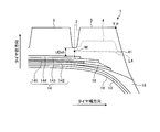
- FIG. 2 and 3 are explanatory views showing a belt layer of the pneumatic tire shown in FIG.
- FIG. 2 shows one side region of the tread portion with the tire equatorial plane CL as a boundary
- FIG. 3 shows a laminated structure of the belt layer 14.
- the thin lines in the belt plies 142 to 145 schematically show the belt cords of the belt plies 142 to 145.
- the belt layer 14 is formed by laminating a pair of cross belts 142 and 143, an additional belt (low angle belt) 144, and a circumferential reinforcing layer 145, and is arranged around the outer periphery of the carcass layer 13 ( (See FIG. 2).
- the pair of cross belts 142 and 143 are configured by rolling a plurality of belt cords made of steel or organic fiber material coated with a coat rubber.
- the pair of cross belts 142 and 143 preferably have a belt angle (inclination angle in the fiber direction of the belt cord with respect to the tire circumferential direction) of 46 [deg] or more and 80 [deg] or less in absolute value, and 51 [deg. More preferably, the belt angle is 70 [deg] or less.
- the pair of cross belts 142 and 143 have belt angles with different signs from each other, and are laminated so that the fiber directions of the belt cords cross each other (cross-ply structure).
- the cross belt 142 located on the inner side in the tire radial direction is called an inner diameter side cross belt
- the cross belt 143 located on the outer side in the tire radial direction is called an outer diameter side cross belt.
- three or more cross belts may be laminated (not shown).
- the additional belt 144 is configured by rolling a plurality of belt cords made of steel or organic fiber material with a coat rubber.
- the additional belt 144 preferably has a belt angle of 10 [deg] or more and 45 [deg] or less in absolute value, and more preferably has a belt angle of 15 [deg] or more and 30 [deg] or less.
- the additional belt 144 is disposed so as to be laminated on the outer side in the tire radial direction of the pair of cross belts 142 and 143. In the configuration of FIG. 1, the additional belt 144 is stacked on the outermost side in the tire radial direction and also serves as a belt cover for the outer diameter side crossing belt 143.
- the circumferential reinforcing layer 145 is formed by winding a steel belt cord covered with a coat rubber in a spiral manner while inclining within a range of ⁇ 5 [deg] with respect to the tire circumferential direction. Specifically, one or more wires are spirally wound around the outer circumference of the inner diameter side crossing belt 142 to form the circumferential reinforcing layer 145. Further, the circumferential reinforcing layer 145 is disposed between the pair of cross belts 142 and 143. Further, the circumferential reinforcing layer 145 is disposed on the inner side in the tire width direction with respect to the left and right edge portions of the pair of cross belts 142 and 143. The circumferential reinforcing layer 145 reinforces the rigidity in the tire circumferential direction.
- the belt layer 14 may have an edge cover (not shown).
- the edge cover is formed by rolling a plurality of belt cords made of steel or organic fiber material with a coating rubber, and has an absolute value of a belt angle of 0 [deg] or more and 5 [deg] or less.
- the edge covers are respectively disposed on the outer sides in the tire radial direction of the left and right edge portions of the outer diameter side cross belt 143 (or the inner diameter side cross belt 142). These edge covers exhibit a tagging effect, so that the difference in diameter growth between the tread portion center region and the shoulder region is alleviated.
- the inner diameter side crossing belt 142 is disposed adjacent to the carcass layer 13. Therefore, the inner diameter side cross belt 142 constitutes the innermost layer in the tire radial direction of the belt layer 14, and no other belt ply is disposed between the inner diameter side cross belt 142 and the carcass layer 13.
- the inner diameter side crossing belt 142 and the outer diameter side crossing belt 143 are adjacent to the circumferential direction reinforcing layer 145 with the circumferential direction reinforcing layer 145 interposed therebetween. Therefore, no other belt ply is disposed between the inner diameter side cross belt 142 and the outer diameter side cross belt 143 and the circumferential reinforcing layer 145.
- the circumferential reinforcing layer 145 is disposed between the pair of cross belts 142 and 143 (see FIG. 2).
- the present invention is not limited to this, and the circumferential reinforcing layer 145 may be disposed on the outer side in the tire radial direction of the pair of cross belts 142 and 143 (not shown). Further, the circumferential reinforcing layer 145 may be disposed inside the pair of cross belts 142 and 143.
- the additional belt 144 and the outer diameter side crossing belt 143 adjacent to each other have belt angles having different signs (see FIG. 3).
- the belt cord of the additional belt 144 is inclined leftward in the lower part of the figure, and the belt cord of the outer diameter side crossing belt 143 is inclined rightward in the lower part of the figure. ing.
- the belt cord of the additional belt 144 and the belt cord of the outer diameter side crossing belt 143 are inclined in opposite directions to have belt angles with different signs.
- the belt cord of the additional belt 144 and the belt cord of the outer diameter side crossing belt 143 may have the same belt angle (not shown) by inclining in the same direction.
- the additional belt 144 is arranged so as to cover the arrangement area of the outermost circumferential main groove 2 (see FIG. 2). Specifically, the additional belt 144 is disposed over the entire groove width of the outermost circumferential main groove 2. Thereby, the groove bottom of the outermost circumferential main groove 2 is reinforced. When the additional belt 144 has a split structure (not shown), each divided portion of the additional belt 144 is disposed so as to cover the entire width of the outermost circumferential main groove 2.
- the width Wb4 of the additional belt 144 and the width Wb3 of the outer diameter side crossing belt 143 have a relationship of 0.75 ⁇ Wb4 / Wb3 ⁇ 0.95 (see FIG. 3). Therefore, the additional belt 144 is narrower than the outer diameter side crossing belt 143.
- the ratio Wb4 / Wb3 preferably has a relationship of 0.80 ⁇ Wb4 / Wb3 ⁇ 0.90.
- the width Wb4 of the additional belt 144 and the width Ws of the circumferential reinforcing layer 145 have a relationship of 1.02 ⁇ Wb4 / Ws (see FIG. 3). Therefore, the additional belt 144 is wider than the circumferential reinforcing layer 145. Further, it is preferable that the additional belt 144 extends to the outer side in the tire width direction than the outermost circumferential main groove 2 (see FIG. 2).
- the upper limit of the ratio Wb4 / Ws is not particularly limited, but is limited by the relationship between the ratio Wb4 / Wb3 and the later-described ratio Ws / Wb3.
- the width of the belt ply is a distance in the tire rotation axis direction between the left and right ends of each belt ply, and is measured while a tire is mounted on a specified rim and a specified internal pressure is applied and no load is applied.
- the width of the belt ply is measured as the distance between the outer sides in the tire width direction of the left and right divided portions.
- each belt ply has a symmetrical structure with the tire equatorial plane CL as the center. For this reason, the distance from the tire equatorial plane CL to the end of the belt ply on the outer side in the tire width direction is the half width of the belt ply.
- the stipulated rim is an “applicable rim” defined in JATMA, a “Design Rim” defined in TRA, or a “Measuring Rim” defined in ETRTO.
- the specified internal pressure refers to the “maximum air pressure” specified by JATMA, the maximum value of “TIRE LOAD LIMITS AT VARIOUS COLD INFLATION PRESSURES” specified by TRA, or “INFLATION PRESSURES” specified by ETRTO.
- the specified load is the “maximum load capacity” specified in JATMA, the maximum value of “TIRE LOAD LIMITS AT VARIOUS COLD INFLATION PRESSURES” specified in TRA, or “LOAD CAPACITY” specified in ETRTO.
- the specified internal pressure is air pressure 180 [kPa]
- the specified load is 88 [%] of the maximum load capacity.
- the belt cord of the additional belt 144 is a steel wire and has an end number of 15 [lines / 50 mm] or more and 25 [lines / 50 mm] or less.
- the tire circumferential rigidity of the belt layer is increased by the circumferential reinforcing layer, so that there is a problem that separation of the peripheral rubber at the edge portion of the belt ply is likely to occur. Such a problem remarkably appears particularly under long-term use conditions with a high internal pressure and a high load.
- the retreaded tire is a tire that is reused by replacing the tread rubber of a tire whose remaining groove has reached the end of its life, and is manufactured by two methods, a pre-curing method and a remolding method.
- Precured retreaded tires are manufactured by cutting off the tread rubber of a used tire by buffing to form a base tire, and then bonding a vulcanized precured tread with a tread pattern when new to the base tire.
- the Remolded retreaded tires are obtained by cutting off the tread rubber of a used tire by buffing to form a base tire, winding an unvulcanized tread rubber around the base tire, and adding it using a molding die having a tread pattern. Manufactured by sulfur molding.
- the used tire is inflated and buffed.
- the diameter growth of the tire increases in the left and right shoulder regions.
- the end portion of the belt ply in the shoulder region is easily exposed on the surface of the base tire by the buffing process. Since such a base tire cannot be used as a retread tire, a device for increasing the yield of the base tire is required.
- belt edge separation separation of peripheral rubber at the belt layer end
- a device for suppressing belt edge separation is required at the stage of a new tire.
- the belt edge separation inside the base tire cannot be determined by the appearance of the tire, the presence or absence of occurrence is inspected by a dedicated inspection device.
- the pair of cross belts 142 and 143 function as a high-angle belt, and rigidity in the tire width direction is ensured.
- the circumferential reinforcing layer 145 and the additional belt 144 function as a low-angle belt, and the rigidity in the tire circumferential direction is ensured.
- the rigidity balance between the tire circumferential direction and the tire width direction is optimized, and deformation of the tread portion over time is suppressed. Thereby, the yield of the base tire at the time of tire retreading is improved, and the retreading performance of the tire is improved.
- the distance Gcc from the tread profile to the tire inner peripheral surface on the tire equatorial plane CL and the distance Gsh from the tread end P to the tire inner peripheral surface are 1.10 ⁇ Gsh / Gcc ⁇ 1.50 relationship.
- the ratio Gsh / Gcc is preferably in the range of 1.20 ⁇ Gsh / Gcc ⁇ 1.50.
- the distance Gcc is measured as a distance from the intersection of the tire equator plane CL and the tread profile to the intersection of the tire equator plane CL and the tire inner peripheral surface in a sectional view in the tire meridian direction. Therefore, in the configuration having the circumferential main groove 2 on the tire equatorial plane CL as in the configuration of FIGS. 1 and 2, the distance Gcc is measured excluding the circumferential main groove 2.
- the distance Gsh is measured as the length of a perpendicular line dropped from the tread end P to the tire inner peripheral surface in a sectional view in the tire meridian direction.
- the pneumatic tire 1 includes an inner liner 18 on the inner peripheral surface of the carcass layer 13, and the inner liner 18 is arranged over the entire inner peripheral surface of the tire.
- the distance Gcc and the distance Gsh are measured using the surface of the inner liner 18 as a reference (tire inner peripheral surface).
- the end wear surface WE of the circumferential main groove 2 is drawn in a sectional view in the tire meridian direction.
- the end wear surface WE is a surface estimated from a wear index existing in the tire. Further, the end wear surface WE is measured in a state of the tire alone with the tire in a non-inflated state. In a general pneumatic tire, the end wear surface WE is on a curve substantially parallel to the tread profile.
- the distance Dcc from the circumferential reinforcing layer 145 to the terminal wear surface WE on the tire equatorial plane CL and the distance De from the end of the circumferential reinforcing layer 145 to the terminal wear surface WE are 0.95 ⁇ De /Dcc ⁇ 1.05.
- the distance Dcc and the distance De are measured in a state of the tire alone with the tire in a non-inflated state. Further, the measurement point on the circumferential reinforcing layer 145 side is defined by a curve connecting the center points of the belt cords constituting the circumferential reinforcing layer 145 in a sectional view in the tire meridian direction. The end of the circumferential reinforcing layer 145 is defined with reference to the outermost belt cord in the tire width direction among the belt cords constituting the circumferential reinforcing layer 145.
- FIG. 4 is an explanatory view showing the operation of the pneumatic tire shown in FIG. The figure shows the ground contact states of tires having different ratios De / Dcc and Gsh / Gcc, respectively.
- the tread profile has a shoulder drop shape in which the outer diameter decreases from the tire equatorial plane CL toward the tread end P in a tire non-contact state (not shown). For this reason, at the time of tire contact, as shown in FIG. 4A, the tread portion shoulder region is greatly deformed to the road surface side (tire radial direction outer side).
- the tread profile is generally flat (substantially parallel to the tire rotation axis). It has a shape (see FIGS. 1 and 2). For this reason, as shown in FIG.4 (b), the deformation amount of the tread part shoulder region at the time of tire contact is small.
- the shoulder land portion contact at the time of tire contact is compared with the configuration in which the ratio De / Dcc is substantially equal.
- the ground pressure increases.
- the groove depth GDcc of the circumferential main groove 2 near the tire equatorial plane CL, the groove depth GDsh of the outermost circumferential main groove 2, and the position of the open end 41 of the lug groove 4 of the shoulder land portion 3 Is defined as a reference (see FIGS. 5 and 6).
- the ratio Gsh / Gcc is set to be large and the shoulder portion has a thick structure, so that it is possible to prevent the belt ply from being exposed while appropriately securing the buffing amount. As a result, the yield of the base tire is improved.
- FIG. 5 is an explanatory view showing the pneumatic tire shown in FIG. 1. This figure is a duplicate of FIG. 2, and instead of the dimensions and symbols shown in FIG. 2, dimensions and symbols necessary for the description of the sub-groove gauge are newly added.
- the groove depth GDsh of the outermost circumferential main groove 2 and the sub-groove gauge UDsh have a relationship of 0.20 ⁇ UDsh / GDsh.
- the groove depth GDcc of the circumferential main groove 2 closest to the tire equatorial plane CL and the sub-groove gauge UDcc preferably have a relationship of 0.15 ⁇ UDcc / GDcc, and 0.20 ⁇ UDcc It is more preferable to have a relationship of / GDcc.
- the groove depths GDsh and GDcc of the circumferential main groove 2 are measured as the distance between the tread profile and the groove bottom (maximum depth position) of the circumferential main groove 2. Further, the groove depths GDsh and GDcc are measured excluding the bottom upper part such as a stone ejector formed at the groove bottom. Further, the groove depths GDsh and GDcc depend on the tire size, but are generally set within the ranges of 10 [mm] ⁇ GDsh ⁇ 25 [mm] and 10 [mm] ⁇ GDcc ⁇ 25 [mm].
- the sub-groove gauges UDsh and UDcc of the circumferential main groove 2 are the groove bottom of the circumferential main groove 2 and the belt layer 14 (more specifically, the outer side in the tire radial direction of the belt cord of the belt ply at the outermost side in the tire radial direction). Measured as the distance to the arc connecting the tops of
- the circumferential main groove 2 closest to the tire equatorial plane CL refers to the circumferential main groove 2 when the circumferential main groove 2 is present on the tire equatorial plane CL (see FIG. 5).
- the circumferential main groove 2 located closest to the tire equatorial plane CL among the plurality of circumferential main grooves 2 is referred to. .
- the upper limit of the ratio UDsh / GDsh and the ratio UDcc / GDcc is not particularly limited. However, if the sub-groove gauges UDsh, UDcc are excessive, the tread gauge increases and the rolling resistance of the tire decreases, which is not preferable. Therefore, it is preferable that the upper limits of the ratio UDsh / GDsh and the ratio UDcc / GDcc are appropriately set in consideration of this point. Specifically, the ratio UDsh / GDsh and the ratio UDcc / GDcc are preferably in the ranges of UDsh / GDsh ⁇ 0.7 and UDcc / GDcc ⁇ 0.7.
- the ratio UDsh / GDsh and the ratio UDcc / GDcc have a relationship of UDcc / GDcc ⁇ UDsh / GDsh. Therefore, the sub-gage gauge ratio UDsh / GDsh of the outermost circumferential main groove 2 is set larger than the sub-groove gauge ratio UDcc / GDcc of the circumferential main groove 2 in the vicinity of the tire equatorial plane CL. Thereby, the tread shape having the above-described ratio Gsh / Gcc can be realized while optimizing the groove depths GDsh and GDcc of each circumferential main groove 2.
- the groove depth GDsh of the outermost circumferential main groove 2 and the groove depth GDcc of the circumferential main groove 2 in the vicinity of the tire equatorial plane CL have a relationship of 1.0 ⁇ GDsh / GDcc ⁇ 1.2. Is preferred. As a result, the groove depth ratio GDsh / GDcc is optimized.
- circumferential main groove 2 In the configuration in which the circumferential main groove 2 is between the circumferential main groove 2 and the outermost circumferential main groove 2 closest to the tire equatorial plane CL (see FIGS. 1 and 5), these circumferential main grooves are generally used.
- the groove depth and sub-groove gauge of the groove 2 are appropriately set based on the groove depths GDsh and GDcc and the sub-groove gauges UDsh and UDcc.
- the pneumatic tire 1 has the following configuration so that the user can properly determine the rehabilitation time of the tire.
- FIG. 6 to 9 are enlarged cross-sectional views showing a shoulder portion of the pneumatic tire shown in FIG.
- Each of these drawings shows a pneumatic tire 1 having the same structure, and shows a state of a shoulder portion when the tire is mounted on a specified rim to apply a specified internal pressure and is in a no-load state.
- the open end 41 of the lug groove 4 is disposed on the outer side in the tire radial direction with respect to the straight line L1. Specifically, it is preferable that the opening end 41 of the lug groove 4 is disposed with a distance of 2 [mm] or more with respect to the straight line L1. And the opening edge part 41 of the lug groove 4 is used as a mark for judging the retreading time of a tire.
- the shoulder wear portion can be removed by buffing while preventing the belt layer 14 from being exposed to the surface of the base tire.
- the opening edge part 41 of the lug groove 4 functions as a mark for judging the retreading time of a tire.
- all the belt plies 142 to 145 constituting the belt layer 14 are on the inner side in the tire radial direction from the curve L2.
- the end portions of all the belt plies 142 to 145 located on the outer side in the tire width direction with respect to the outermost circumferential main groove 2 are located on the inner side in the tire radial direction with respect to the curve L2. This prevents the belt layer 14 from being exposed to the surface of the base tire during the buffing process.
- the sub-gage gauge UDsh of the outermost circumferential main groove 2 and the distance ⁇ Drg in the tire radial direction from the intersection point Q to the open end 41 of the lug groove 4 are ⁇ 1.0 ⁇ ⁇ Drg with the tire radial direction outer side being positive.
- the ratio ⁇ Drg / UDsh is preferably set to a relationship of ⁇ 1.0 ⁇ ⁇ Drg / UDsh ⁇ 0, and more preferably set to a relationship of ⁇ 0.5 ⁇ ⁇ Drg / UDsh ⁇ ⁇ 0.1. preferable.
- the opening end portion 41 of the lug groove 4 is arranged on the inner side in the tire radial direction from the intersection point Q, so that the tire rehabilitation time can be delayed and the primary life of the tire can be extended. Further, when the ratio ⁇ Drg / UDsh is in the range of ⁇ 1.0 ⁇ ⁇ Drg / UDsh (further, ⁇ 0.5 ⁇ ⁇ Drg / UDsh), it can be accurately determined whether or not the tire can be renewed.
- a straight line L3 connecting the groove bottom of the outermost circumferential main groove 2 and the open end 41 of the lug groove 4 is drawn in a sectional view in the tire meridian direction.
- a straight line L ⁇ b> 4 connecting the midpoint M of the sub-gage gauge UDsh of the outermost circumferential main groove 2 and the open end 41 of the lug groove 4 is drawn in a cross-sectional view in the tire meridian direction.
- the midpoint M of the sub-groove gauge UDsh refers to the midpoint of two points that define the sub-groove gauge UDsh.
- the groove depth GDsh and the sub-groove gauge UDsh of the outermost circumferential main groove 2 and the distance Drg in the tire radial direction from the tire ground contact end T to the open end 41 of the lug groove 4 are 0. 7 ⁇ Drg / (GDsh + UDsh) ⁇ 1.1.
- FIGS. 10 to 12 are explanatory views showing modifications of the pneumatic tire shown in FIG. These drawings show modifications of the lug groove 4 of the shoulder land portion 3.
- the lug groove 4 extends in the tire width direction, penetrates the shoulder land portion 3, and opens to the outermost circumferential main groove 2 and the buttress portion, respectively. Further, a bottom upper portion 42 is provided in the shoulder land portion 3.
- the present invention is not limited to this, and the lug groove 4 may be opened at least in the buttress portion.
- the open end 41 of the lug groove 4 functions as a mark for judging the tire regeneration time.
- the lug groove 4 may open to the buttress portion at one end portion and terminate in the shoulder land portion 3 at the other end portion. Further, as shown in FIG. 11, the lug groove 4 may be formed only in the buttress portion, and may extend from the tire ground contact end T to the inside in the tire radial direction along the buttress portion. Further, as shown in FIG. 12, the lug groove 4 may be opened to the outermost circumferential main groove 2 while being raised by the bottom upper part 42.
- FIG. 13 is an explanatory view illustrating a modified example of the pneumatic tire depicted in FIG. 1. This figure shows a configuration having a round shoulder.
- the shoulder portion has a square shape, and the tire ground contact end T and the tread end P coincide with each other. That is, in the configuration having the square-shaped shoulder portion, the point of the square-shaped edge portion becomes the tread end P.
- the shoulder portion may have a round shape as shown in FIG.
- the intersection P ′ between the profile of the tread portion and the profile of the sidewall portion is taken, and the perpendicular foot drawn from the intersection P ′ to the shoulder portion. Is the tread edge P. For this reason, normally, the tire ground contact edge T and the tread edge P are in different positions.
- the ratio Gsh / Gcc is preferably in the range of 1.20 ⁇ Gsh / Gcc ⁇ 1.40.
- the tread width TW and the tire total width SW have a relationship of 0.83 ⁇ TW / SW ⁇ 0.95. Further, the ratio TW / SW is preferably in the range of 0.85 ⁇ TW / SW ⁇ 0.93.
- the total tire width SW is the linear distance between the sidewalls (including all parts of the tire side pattern, characters, etc.) when the tire is mounted on the specified rim to provide the specified internal pressure and is in an unloaded state.
- the tread width TW is the distance between the left and right tread ends P, P in the tire rotation axis direction, and is measured as a no-load state while attaching a tire to a specified rim and applying a specified internal pressure.
- tread width TW and the cross-sectional width Wca of the carcass layer 13 have a relationship of 0.82 ⁇ TW / Wca ⁇ 0.92.
- the cross-sectional width Wca of the carcass layer 13 refers to a linear distance between the left and right maximum width positions of the carcass layer 13 when a tire is mounted on a specified rim to apply a specified internal pressure and is in an unloaded state.
- the width Wb3 of the narrower cross belt in FIG. 1, the outer diameter side cross belt 143 and the width Ws of the circumferential reinforcing layer 145 among the inner diameter side cross belt 142 and the outer diameter side cross belt 143.
- the width Ws of the circumferential reinforcing layer 145 is appropriately secured.
- the widths Wb2 and Wb3 of the cross belts 142 and 143 are the distances in the tire rotation axis direction of the left and right ends of the cross belts 142 and 143. As measured.
- the width Wb2 of the wide cross belt in FIG. 1, the inner diameter side cross belt 142) of the inner diameter side cross belt 142 and the outer diameter side cross belt 143, and the cross-sectional width Wca of the carcass layer 13
- the ratio Wb2 / Wca is preferably in the range of 0.78 ⁇ Wb2 / Wca ⁇ 0.83.
- width Ws of the circumferential reinforcing layer 145 and the cross-sectional width Wca of the carcass layer 13 have a relationship of 0.60 ⁇ Ws / Wca ⁇ 0.70.
- the tread width TW and the width Ws of the circumferential reinforcing layer 145 have a relationship of 0.70 ⁇ Ws / TW ⁇ 0.90.
- the circumferential reinforcing layer 145 has a narrow cross belt (in FIG. 1, the outer diameter side cross) in the pair of cross belts (the inner diameter side cross belt 142 and the outer diameter side cross belt 143).
- the belt 143) is disposed on the inner side in the tire width direction than the left and right edge portions.
- the width Wb3 of the narrow cross belt 143 and the distance S from the edge portion of the circumferential reinforcing layer 145 to the edge portion of the narrow cross belt 143 satisfy 0.03 ⁇ S / Wb3 ⁇ 0.12. It is preferable to be in the range.
- the distance S of the circumferential reinforcing layer 145 is measured as a distance in the tire width direction when the tire is mounted on a specified rim to apply a specified internal pressure and is in a no-load state.
- the circumferential reinforcing layer 145 is formed by winding a single steel wire in a spiral shape.
- the present invention is not limited to this, and the circumferential reinforcing layer 145 may be formed by spirally winding a plurality of wires while running parallel to each other (multiple winding structure).
- the number of wires is preferably 5 or less.
- the winding width per unit when multiple windings of five wires are 12 [mm] or less. Thereby, a plurality of wires (2 or more and 5 or less) can be properly wound while being inclined within a range of ⁇ 5 [deg] with respect to the tire circumferential direction.
- the belt cords of the pair of cross belts 142 and 143 are preferably steel wires, and the pair of cross belts 142 and 143 preferably have an end number of 18 [lines / 50 mm] or more and 28 [lines / 50 mm] or less. It is more preferable to have an end number of [lines / 50 mm] or more and 25 [lines / 50 mm] or less.
- the belt cord of the circumferential reinforcing layer 145 is preferably a steel wire and has an end number of 17 [pieces / 50 mm] or more and 30 [pieces / 50 mm] or less. Thereby, the strength of each belt ply 142, 143, 145 is ensured appropriately.
- the modulus E2 and E3 when the coat rubber of the pair of cross belts 142 and 143 is 100% stretched and the modulus Es when the coat rubber of the circumferential reinforcing layer 145 is 100% stretched are 0.90 ⁇ Es / E2 ⁇ 1.10. And it is preferable to have a relationship of 0.90 ⁇ Es / E3 ⁇ 1.10.
- the modulus Es when the coated rubber of the circumferential reinforcing layer 145 is 100% stretched is preferably in the range of 4.5 [MPa] ⁇ Es ⁇ 7.5 [MPa]. Thereby, the modulus of each belt ply 142, 143, 145 is optimized.
- the modulus at 100% elongation is measured by a tensile test at room temperature according to JIS-K6251 (using No. 3 dumbbell).
- the breaking elongations ⁇ 2 and ⁇ 3 of the coat rubber of the pair of cross belts 142 and 143 are in the range of ⁇ 2 ⁇ 200 [%] and ⁇ 3 ⁇ 200 [%].
- the elongation at break ⁇ s of the coated rubber of the circumferential reinforcing layer 145 is preferably in the range of ⁇ s ⁇ 200 [%].
- Elongation at break is 2 [mm] using a tensile tester (INSTRON 5585H, manufactured by Instron) in accordance with JIS-K7161 for test pieces of JIS-K7162 standard type 1B (dumbbell type with a thickness of 3 mm). / Min].
- the elongation at a tensile load of 100 [N] to 300 [N] is 1.0 [%] or more and 2.5 [%] or less.
- the elongation at a tensile load of 500 [N] to 1000 [N] is preferably 0.5 [%] or more and 2.0 [%] or less.
- Such a belt cord (high elongation steel wire) has a better elongation at low load than normal steel wire, and can withstand the load applied to the circumferential reinforcing layer 145 from the time of manufacture to the time of tire use. This is preferable in that damage to the circumferential reinforcing layer 145 can be suppressed.
- the elongation of the belt cord is measured according to JIS-G3510.
- the breaking elongation of the tread rubber 15 is preferably in the range of 400 [%] or more, and more preferably 450 [%] or more. Thereby, the strength of the tread rubber 15 is ensured.
- the upper limit of the elongation at break of the tread rubber 15 is not particularly limited, but is restricted by the type of rubber compound of the tread rubber 15.
- the tread rubber 15 preferably has a hardness of 60 or more. Thereby, the strength of the tread rubber 15 is ensured appropriately.
- the upper limit of the hardness of the tread rubber 15 is not particularly limited, but is restricted by the type of rubber compound of the tread rubber 15.
- Rubber hardness means JIS-A hardness according to JIS-K6263.
- FIG. 14 is an explanatory view showing a modified example of the pneumatic tire depicted in FIG. 1. This figure shows an enlarged view of the end of the belt layer 14 on the outer side in the tire width direction. In the same figure, the circumferential reinforcing layer 145 and the belt edge cushion 19 are hatched.
- the circumferential reinforcing layer 145 is disposed on the inner side in the tire width direction from the left and right edge portions of the narrow cross belt 143 of the pair of cross belts 142 and 143. Further, the belt edge cushion 19 is sandwiched and disposed at a position between the pair of cross belts 142 and 143 and corresponding to the edge portions of the pair of cross belts 142 and 143. Specifically, the belt edge cushion 19 is disposed on the outer side in the tire width direction of the circumferential reinforcing layer 145 and is adjacent to the circumferential reinforcing layer 145, and a pair of ends from the outer end of the circumferential reinforcing layer 145 in the tire width direction.
- the cross belts 142 and 143 are arranged so as to extend to the outer ends in the tire width direction.
- the belt edge cushion 19 has a structure thicker than the circumferential reinforcing layer 145 as a whole by increasing the thickness toward the outer side in the tire width direction. .
- the belt edge cushion 19 has a modulus E at 100% extension lower than the coat rubber of each cross belt 142, 143.
- the modulus E at 100% extension of the belt edge cushion 19 and the modulus Eco of the coat rubber have a relationship of 0.60 ⁇ E / Eco ⁇ 0.95.
- the belt edge cushion 19 has a two-color structure including a stress relaxation rubber 191 and an end relaxation rubber 192.
- the stress relaxation rubber 191 is disposed between the pair of cross belts 142 and 143 and outside the circumferential reinforcing layer 145 in the tire width direction and is adjacent to the circumferential reinforcing layer 145.
- the end relaxation rubber 192 is disposed between the pair of cross belts 142 and 143, and is disposed on the outer side in the tire width direction of the stress relaxation rubber 191 and at a position corresponding to the edge portion of the pair of cross belts 142 and 143. Adjacent to rubber 191.
- the belt edge cushion 19 has a structure in which the stress relaxation rubber 191 and the end relaxation rubber 192 are continuously provided in the tire width direction in the tire meridian cross-sectional view, and the tire of the circumferential reinforcing layer 145 The region from the end portion on the outer side in the width direction to the edge portion of the pair of cross belts 142 and 143 is filled in.
- the modulus Ein when the stress relaxation rubber 191 is stretched 100% and the modulus Es when the coat rubber of the circumferential reinforcing layer 145 is stretched 100% have a relationship of Ein ⁇ Es.
- the modulus Ein of the stress relaxation rubber 191 and the modulus Es of the circumferential reinforcing layer 145 have a relationship of 0.6 ⁇ Ein / Es ⁇ 0.9.
- the modulus Ein when the stress relaxation rubber 191 is stretched 100% and the modulus Eco when the coat rubber of each cross belt 142 and 143 is stretched 100% have a relationship of Ein ⁇ Eco.
- the modulus Ein of the stress relaxation rubber 191 and the modulus Eco of the coat rubber have a relationship of 0.6 ⁇ Ein / Eco ⁇ 0.9.
- the modulus Eout at 100% extension of the end relaxation rubber 192 and the modulus Ein at 100% extension of the stress relaxation rubber 191 have a relationship of Eout ⁇ Ein.
- the modulus Ein at 100% elongation of the stress relaxation rubber 191 is preferably in the range of 4.0 [MPa] ⁇ Ein ⁇ 5.5 [MPa].
- FIG. 15 is an explanatory view showing a modified example of the pneumatic tire shown in FIG. 1. This figure shows one side region of the tread portion with the tire equatorial plane CL as a boundary.
- the additional belt 144 is installed in the outermost layer of the belt layer 14 as shown in FIGS. 2 and 3. For this reason, the inner diameter side crossing belt 142 is disposed in the innermost layer of the belt layer 14 and is adjacent to the carcass layer 13.
- the additional belt 144 may be sandwiched between the carcass layer 13 and the inner diameter side crossing belt 142 and disposed adjacent to them. That is, in the configuration of FIG. 6, the additional belt 144 is disposed on the outer periphery of the carcass layer 13, the inner diameter side cross belt 142 is laminated on the outer periphery of the additional belt 144, and the circumferential reinforcing layer is disposed on the outer periphery of the inner diameter side cross belt 142. 145 and the outer diameter side crossing belt 143 are laminated in order to constitute the belt layer 14.
- the pneumatic tire 1 includes the carcass layer 13, the belt layer 14 disposed outside the carcass layer 13 in the tire radial direction, and the tread rubber 15 disposed outside the belt layer 14 in the tire radial direction. (See FIG. 1).
- at least three circumferential main grooves 2 extending in the tire circumferential direction and a plurality of land portions 3 defined by the circumferential main grooves 2 are provided.
- the belt layer 14 has a belt angle of 46 [deg] or more and 80 [deg] or less in absolute value with respect to the tire circumferential direction, and an inner diameter side cross belt 142 and an outer diameter side having belt angles with mutually different signs.
- the pair of cross belts 142 and 143 function as a high-angle belt, and the rigidity in the tire width direction is ensured.
- the circumferential reinforcing layer 145 and the additional belt 144 function as a low-angle belt, and the rigidity in the tire circumferential direction is ensured.
- the rigidity balance between the tire circumferential direction and the tire width direction is optimized, and deformation of the tread portion over time is suppressed. Thereby, the yield of the base tire at the time of tire retreading improves, and there exists an advantage which the retreading performance of a tire improves.
- the pair of cross belts 142 and 143 function as high-angle belts, and therefore, other high-angle belts (for example, belt angles of 45 [deg] or more and 70 [deg] or less in absolute value).
- the belt ply disposed between the carcass layer and the inner diameter side cross belt can be omitted.
- the circumferential reinforcing layer 145 is disposed between the inner diameter side cross belt 142 and the outer diameter side cross belt 143, a pair of cross belts having a belt angle greatly inclined in the tire width direction. 142 and 143 and a circumferential reinforcing layer 145 having a belt angle greatly inclined in the tire circumferential direction are alternately laminated in the tire radial direction. Then, for example, the tire diameter between the belt plies 142, 143, and 145 is compared with a configuration (not shown) in which the circumferential reinforcing layer is disposed on the tire radial direction inner side or the tire radial direction outer side of the pair of cross belts. Uniform stiffness distribution in the direction. Thereby, there exists an advantage which the belt durability performance of a tire improves.
- the ratio Gsh / Gcc is set to be large (in the range of 1.10 ⁇ Gsh / Gcc) and the shoulder portion has a thick structure.
- the belt ply can be prevented from being exposed while being properly secured.
- the shoulder portion has a thick structure, it is preferable in that the shoulder wear portion can be appropriately excised by buffing even when the shoulder wear portion of the used tire is wide.
- the shoulder land at the time of tire contact is compared with the configuration in which the ratio De / Dcc is substantially equal.
- the contact surface pressure of part 3 increases.
- the radial growth of the tire in the outer region in the tire width direction than the circumferential reinforcing layer 145 is suppressed, and deformation of the belt layer 14 is suppressed.
- the exposure of the belt layer 14 at the time of buffing the used tire is suppressed, and there is an advantage that the yield of the base tire is improved.
- the groove depth GDsh and the sub-groove gauge UDsh of the left and right circumferential main grooves (outermost circumferential main grooves) 2 on the outermost side in the tire width direction are 0.20 ⁇ UDsh / GDsh.
- the sub-groove gauge UDsh of the outermost circumferential main groove 2 is appropriately secured, so that a sufficient buffing amount can be secured so that shoulder wear of the used tire does not remain on the surface of the base tire.
- the width Wb2 of the inner diameter side cross belt 142 is wider than the width Wb3 of the outer diameter side cross belt 143 (see FIGS. 2 and 3). Accordingly, there is an advantage that the durability of the belt layer 14 is maintained, and the belt layer 14 can effectively exert the tag effect.
- the groove depth GDcc of the circumferential main groove 2 closest to the tire equatorial plane CL and the sub-groove gauge UDcc have a relationship of 0.15 ⁇ UDcc / GDcc (see FIG. 5).
- a sufficient buffing amount can be ensured so that the sub-groove gauge UDcc of the circumferential main groove 2 is appropriately secured and the shoulder wear of the used tire does not remain on the surface of the base tire.
- the shoulder land portion 3 includes a lug groove 4 that opens to the buttress portion (see FIG. 6).
- the outermost circumferential direction main groove 2 is located on the outer side in the tire width direction and the outermost side in the tire radial direction.
- the opening end portion 41 of the lug groove 4 is located on the outer side in the tire radial direction than the straight line L1.
- the belts constituting the belt layer 14 are drawn when a curve L ⁇ b> 2 passing through the bottom of the outermost circumferential main groove 2 and parallel to the tire profile is drawn in a sectional view in the tire meridian direction.
- the plies 141 to 145 are on the inner side in the tire radial direction than the curve L2 (see FIG. 7). This prevents the end of the belt ply from being exposed to the surface of the base tire during the buffing process, thereby improving the yield of the base tire.
- the belt layer 14 is All the belt plies 142 to 145 constituting the tire are located on the inner side in the tire radial direction from the straight line L3 (see FIG. 8). This prevents the end of the belt ply from being exposed to the surface of the base tire during the buffing process, thereby improving the yield of the base tire.
- the groove depth GDsh and the sub-groove gauge UDsh of the outermost circumferential main groove 2 and the distance Drg in the tire radial direction from the tire ground contact end T to the open end 41 of the lug groove 4 are 0.7 ⁇ Drg / (GDsh + UDsh) ⁇ 1.1 (see FIG. 6).
- the opening end portion 41 of the lug groove 4 is used as a mark for determining the tire regeneration time, the position of the opening end portion 41 is optimized. Thereby, there exists an advantage which can judge accurately whether a tire can be rehabilitated.
- the left and right end portions of the circumferential reinforcing layer 145 are more in the tire width direction than the left and right circumferential main grooves (outermost circumferential direction main grooves) 2, 2 located on the outermost side in the tire width direction. It is on the outside (see FIGS. 1 and 2).
- the circumferential reinforcing layer 145 extends to the bottom of the outermost circumferential main groove 2 so that the growth of the tire diameter in the outermost circumferential main groove 2 is suppressed.
- the tread width TW and the width Ws of the circumferential reinforcing layer 145 have a relationship of 0.70 ⁇ Ws / TW ⁇ 0.90 (see FIG. 1).
- the amount of deformation of the shoulder land portion 3 at the time of tire contact is effectively reduced by optimizing the ratio Ws / TW (see FIG. 4B).
- the width Ws of the circumferential reinforcing layer 145 is appropriately secured, and the deformation amount of the shoulder land portion 3 at the time of tire contact is reduced. Further, since Ws / TW ⁇ 0.90, deformation at each belt ply end is suppressed when the tire is in contact with the ground, thereby reducing distortion at each belt ply end.
- the width Ws of the circumferential reinforcing layer 145 and the cross-sectional width Wca of the carcass layer 13 have a relationship of 0.60 ⁇ Ws / Wca ⁇ 0.70 (see FIG. 1).
- the rigidity balance between the tire circumferential direction and the tire width direction is optimized by optimizing the width Ws of the circumferential reinforcing layer 145.
- the tread width TW and the cross-sectional width Wca of the carcass layer 13 have a relationship of 0.82 ⁇ TW / Wca ⁇ 0.92 (see FIG. 1).
- the belt layer 14 includes the circumferential reinforcing layer 145, thereby suppressing the radial growth of the center region.
- the ratio TW / Wca is within the above range, the difference in diameter growth between the center region and the shoulder region is alleviated, and the contact pressure distribution in the tire width direction is made uniform. Thereby, there exists an advantage by which the contact pressure distribution of a tire is equalized.
- a laminated body (the belt layer 14 in FIGS. 2 and 3) composed of the inner diameter side cross belt 142, the outer diameter side cross belt 143, the circumferential reinforcing layer 145 and the additional belt 144 is formed as a carcass. Located adjacent to layer 13 (see FIGS. 2 and 3).
- a high-angle belt (belt angle of 45 [deg] or more and 70 [deg] or less in absolute value) is provided between the laminate and the carcass layer.
- one belt ply can be excluded, there is an advantage that the weight of the tire can be reduced.
- the belt cord of the circumferential reinforcing layer 145 is a steel wire and has an end number of 17 [pieces / 50 mm] or more and 30 [pieces / 50 mm] or less.
- the elongation at the time of a tensile load of 100 [N] to 300 [N] at the time of the member of the belt cord constituting the circumferential reinforcing layer 145 is 1.0 [%] or more and 2.5 [ %] Or less.
- the elongation of the belt cord constituting the circumferential reinforcing layer 145 at the time of a tensile load of 500 [N] to 1000 [N] is 0.5 [%] or more and 2.0 [[ %] Or less.
- the circumferential reinforcing layer 145 has a narrower cross belt (in FIG. 1, the outer diameter side crossing in FIG. 1) of the pair of cross belts (the inner diameter side cross belt 142 and the outer diameter side cross belt 143).
- the belt 143) is disposed on the inner side in the tire width direction from the left and right edge portions (see FIG. 3).
- the pneumatic tire 1 is disposed between the pair of cross belts 142 and 143 and on the outer side in the tire width direction of the circumferential reinforcing layer 145 and adjacent to the circumferential reinforcing layer 145, and a pair of An end portion relaxation rubber 192 disposed between the cross belts 142 and 143 and located outside the stress relaxation rubber 191 in the tire width direction and corresponding to the edge portions of the pair of cross belts 142 and 143 and adjacent to the stress relaxation rubber 191. (See FIG. 14).
- the circumferential reinforcing layer 145 is arranged on the inner side in the tire width direction with respect to the left and right edge portions of the narrow cross belt 143 of the pair of cross belts 142 and 143, whereby the edge of the circumferential reinforcing layer 145 There is an advantage that fatigue rupture of peripheral rubber at the portion is suppressed. Further, since the stress relaxation rubber 191 is disposed on the outer side in the tire width direction of the circumferential reinforcing layer 145, the shear strain of the peripheral rubber between the edge portion of the circumferential reinforcing layer 145 and between the cross belts 142 and 143 is relaxed.
- the end relaxation rubber 192 is disposed at a position corresponding to the edge portions of the cross belts 142 and 143, the shear strain of the peripheral rubber at the edge portions of the cross belts 142 and 143 is reduced.
- the modulus Ein of the stress relaxation rubber 191 when stretched 100% and the modulus Eco when the coat rubber of the pair of cross belts (the inner diameter side cross belt 142 and the outer diameter side cross belt 143) are stretched 100%.
- the modulus Ein of the stress relaxation rubber 191 is optimized, and there is an advantage that the shear strain of the peripheral rubber between the edge portion of the circumferential reinforcing layer 145 and the cross belts 142 and 143 is relaxed.
- the modulus Ein of the stress relaxation rubber 191 when stretched 100% and the coat rubber of the pair of cross belts 142 and 143 (the inner diameter side cross belt 142 and the outer diameter side cross belt 143) are stretched 100%.
- the modulus Eco has a relationship of 0.60 ⁇ Ein / Eco ⁇ 0.90 (see FIG. 14).
- the modulus Ein of the stress relaxation rubber 191 is optimized, and there is an advantage that the shear strain of the peripheral rubber between the edge portion of the circumferential reinforcing layer 145 and the cross belts 142 and 143 is relaxed.
- the modulus Ein at the time of 100% elongation of the stress relaxation rubber 191 is in the range of 4.0 [MPa] ⁇ Ein ⁇ 5.5 [MPa] (see FIG. 14).
- the modulus Ein of the stress relaxation rubber 191 is optimized, and there is an advantage that the shear strain of the peripheral rubber between the edge portion of the circumferential reinforcing layer 145 and the cross belts 142 and 143 is relaxed.
- the circumferential reinforcing layer 145 has a narrower cross belt (in FIG. 1, the outer diameter side crossing in FIG. 1) of the pair of cross belts (the inner diameter side cross belt 142 and the outer diameter side cross belt 143).
- the belt 143) is disposed on the inner side in the tire width direction from the left and right edge portions (see FIG. 1).
- the width Wb3 of the narrow cross belt 143 and the distance S from the edge portion of the circumferential reinforcing layer 145 to the edge portion of the narrow cross belt 143 satisfy 0.03 ⁇ S / Wb3 ⁇ 0.12. It is in range (see FIG. 3).
- the pneumatic tire 1 is a heavy load having a flatness of 40% to 75% in a state where the tire is assembled on a regular rim and a normal internal pressure and a normal load are applied to the tire. It is preferably applied to heavy duty tires.
- the heavy load tire has a larger load when the tire is used than the tire for a passenger car. For this reason, the radial difference between the arrangement region of the circumferential reinforcing layer and the region outside the circumferential direction of the circumferential reinforcing layer is likely to be large. Further, in a tire having a low flatness ratio as described above, the ground contact shape tends to be a drum shape. Therefore, the effect of the circumferential reinforcing layer 145 is remarkably obtained by using the heavy duty tire as an application target.
- 16 and 17 are charts showing the results of the performance test of the pneumatic tire according to the embodiment of the present invention.
- test vehicle 4 ⁇ 2 tractor trailer, runs with test tires on it, and 100 test tires that have worn down to the opening of the lug groove on the shoulder land are extracted for each specification. Then, these test tires are buffed, and the exposure of the belt ply on the surface of the base tire and the remaining of the groove bottom line of the circumferential main groove are observed to evaluate the possibility of rehabilitation.
- This evaluation is preferable as the numerical value increases. In particular, if the evaluation is 80 [%] or more, there is an effect having a sufficient advantage over the conventional example, and if the evaluation is 85 [%] or more, it can be said that there is an extremely advantageous effect.
- the test tire of Example 1 has the configuration described in FIGS.
- the belt plies 142 to 145 of the belt layer 14 are located on the inner side in the tire width direction from the virtual line L2 drawn from the groove bottom of the outermost circumferential main groove 2.
- the test tires of Examples 2 to 28 are modifications of the test tire 1 of Example 1.
- the conventional test tire does not include the circumferential reinforcing layer 145 in the configuration shown in FIGS.
- a high-angle belt having a belt angle of 60 [deg] is provided between the inner diameter side crossing belt 142 and the carcass layer 13. Therefore, the belt layer 14 has a structure in which four belt plies are laminated. Further, the pair of cross belts 142 and 143 have a belt angle closer to the tire circumferential direction (45 [deg] or less).
Landscapes
- Engineering & Computer Science (AREA)
- Mechanical Engineering (AREA)
- Tires In General (AREA)
Description
図1は、この発明の実施の形態にかかる空気入りタイヤを示すタイヤ子午線方向の断面図である。同図は、空気入りタイヤ1の一例として、長距離輸送用のトラック、バスなどに装着される重荷重用ラジアルタイヤを示している。なお、符号CLは、タイヤ赤道面である。また、同図では、トレッド端Pとタイヤ接地端Tとが、一致している。また、同図では、周方向補強層145にハッチングを付してある。
図2および図3は、図1に記載した空気入りタイヤのベルト層を示す説明図である。これらの図において、図2は、タイヤ赤道面CLを境界としたトレッド部の片側領域を示し、図3は、ベルト層14の積層構造を示している。なお、図3では、各ベルトプライ142~145中の細線が各ベルトプライ142~145のベルトコードを模式的に示している。
また、この空気入りタイヤ1では、相互に隣接する付加ベルト144と外径側交差ベルト143とが、異符号のベルト角度を有する(図3参照)。例えば、図3の構成では、付加ベルト144のベルトコードが、同図下方に向かって左側に傾斜し、また、外径側交差ベルト143のベルトコードが、同図下方に向かって右側に傾斜している。このため、付加ベルト144のベルトコードと外径側交差ベルト143のベルトコードとが、逆方向に傾斜することにより、異符号のベルト角度を有している。
トラック・バスなどに装着される近年の重荷重用タイヤは、低い偏平率を有する一方で、ベルト層に周方向補強層を配置することにより、トレッド部の形状を保持している。具体的には、周方向補強層が、トレッド部センター領域に配置されてタガ効果を発揮することにより、トレッド部の径成長を抑制してトレッド部の形状を保持している。
また、この空気入りタイヤ1では、タイヤ赤道面CLにおけるトレッドプロファイルからタイヤ内周面までの距離Gccと、トレッド端Pからタイヤ内周面までの距離Gshとが、1.10≦Gsh/Gcc≦1.50の関係を有する。また、比Gsh/Gccが、1.20≦Gsh/Gcc≦1.50の範囲にあることが好ましい。
図5は、図1に記載した空気入りタイヤを示す説明図である。同図は、図2の複製であり、図2に記載した寸法および符号に代えて、溝下ゲージの説明に必要な寸法および符号を新たに追加している。
上記のように、ベルト層に周方向補強層を有するタイヤでは、ショルダー摩耗が生じ易い傾向にある。このショルダー摩耗が大きく進行すると、バフ処理によりショルダー摩耗を除去することができず、使用済みタイヤを更生できない。これは、ショルダー摩耗を除去するために大きくバフ研磨すると、ベルト層の端部が台タイヤの表面に露出するためである。
図13は、図1に記載した空気入りタイヤの変形例を示す説明図である。同図は、ラウンド形状のショルダー部を有する構成を示している。
また、図1において、トレッド幅TWと、タイヤ総幅SWとが、0.83≦TW/SW≦0.95の関係を有する。また、比TW/SWが、0.85≦TW/SW≦0.93の範囲にあることが好ましい。
図14は、図1に記載した空気入りタイヤの変形例を示す説明図である。同図は、ベルト層14のタイヤ幅方向外側の端部の拡大図を示している。また、同図では、周方向補強層145およびベルトエッジクッション19にハッチングを付してある。
図15は、図1に記載した空気入りタイヤの変形例を示す説明図である。同図は、タイヤ赤道面CLを境界としたトレッド部の片側領域を示している。
以上説明したように、この空気入りタイヤ1は、カーカス層13と、カーカス層13のタイヤ径方向外側に配置されるベルト層14と、ベルト層14のタイヤ径方向外側に配置されるトレッドゴム15とを備える(図1参照)。また、タイヤ周方向に延在する少なくとも3本の周方向主溝2と、これらの周方向主溝2に区画されて成る複数の陸部3とを備える。また、ベルト層14が、タイヤ周方向に対して絶対値で46[deg]以上80[deg]以下のベルト角度を有すると共に相互に異符号のベルト角度を有する内径側交差ベルト142および外径側交差ベルト143と、タイヤ周方向に対して±5[deg]の範囲内にあるベルト角度を有すると共に内径側交差ベルト142および外径側交差ベルト143の間に配置される周方向補強層145とを備える(図2および図3参照)。また、タイヤ赤道面CLにおけるトレッドプロファイルからタイヤ内周面までの距離Gccと、トレッド端Pからタイヤ内周面までの距離Gshとが、1.10≦Gsh/Gccの関係を有する。
また、この空気入りタイヤ1は、タイヤが正規リムにリム組みされると共にタイヤに正規内圧および正規荷重が付与された状態にて、偏平率が40[%]以上75[%]以下である重荷重用タイヤに適用されることが好ましい。重荷重用タイヤでは、乗用車用タイヤと比較して、タイヤ使用時の負荷が大きい。このため、周方向補強層の配置領域と、周方向補強層よりもタイヤ幅方向外側の領域との径差が大きくなり易い。また、上記のような低い偏平率を有するタイヤでは、接地形状が鼓形状となり易い。そこで、かかる重荷重用タイヤを適用対象とすることにより、周方向補強層145の作用効果が顕著に得られる。
Claims (16)
- カーカス層と、前記カーカス層のタイヤ径方向外側に配置されるベルト層と、前記ベルト層のタイヤ径方向外側に配置されるトレッドゴムとを備えると共に、タイヤ周方向に延在する少なくとも3本の周方向主溝と、これらの周方向主溝に区画されて成る複数の陸部とを備える空気入りタイヤであって、
前記ベルト層が、
タイヤ周方向に対して絶対値で46[deg]以上80[deg]以下のベルト角度を有すると共に相互に異符号のベルト角度を有する内径側交差ベルトおよび外径側交差ベルトと、
タイヤ周方向に対して±5[deg]の範囲内にあるベルト角度を有すると共に前記内径側交差ベルトおよび前記外径側交差ベルトの間に配置される周方向補強層とを備え、且つ、
タイヤ赤道面におけるトレッドプロファイルからタイヤ内周面までの距離Gccと、トレッド端からタイヤ内周面までの距離Gshとが、1.10≦Gsh/Gccの関係を有することを特徴とする空気入りタイヤ。 - タイヤ子午線方向の断面視にて、前記周方向主溝の末端摩耗面WEを引くときに、タイヤ赤道面上における前記周方向補強層から末端摩耗面WEまでの距離Dccと、前記周方向補強層の端部から末端摩耗面WEまでの距離Deとが、1.06≦De/Dccの関係を有する請求項1に記載の空気入りタイヤ。
- タイヤ幅方向の最も外側にある左右の前記周方向主溝の溝深さGDshおよび溝下ゲージUDshが、0.20≦UDsh/GDshの関係を有する請求項1または2に記載の空気入りタイヤ。
- 前記内径側交差ベルトの幅Wb2が、前記外径側交差ベルトの幅Wb3よりも広い請求項1~3のいずれか一つに記載の空気入りタイヤ。
- タイヤ赤道面に最も近い前記周方向主溝の溝深さGDccおよび溝下ゲージUDccが、0.15≦UDcc/GDccの関係を有する請求項1~4のいずれか一つに記載の空気入りタイヤ。
- 前記周方向主溝のうちタイヤ幅方向の最も外側にある左右の前記周方向主溝を最外周方向主溝と呼ぶと共に、前記左右の最外周方向主溝よりもタイヤ幅方向外側にある前記陸部をショルダー陸部と呼ぶときに、
前記ショルダー陸部が、バットレス部に開口するラグ溝を備え、且つ、
タイヤ子午線方向の断面視にて、前記ベルト層を構成する複数のベルトプライの端部のうち前記最外周方向主溝よりもタイヤ幅方向外側かつタイヤ径方向の最も外側にある端部からタイヤ回転軸に平行な直線L1を引くときに、
前記ラグ溝の開口端部が、直線L1よりもタイヤ径方向外側にある請求項1~5のいずれか一つに記載の空気入りタイヤ。 - タイヤ子午線方向の断面視にて、前記最外周方向主溝の溝底を通りタイヤプロファイルに平行な曲線L2を引くときに、
前記ベルト層を構成するすべてのベルトプライが、曲線L2よりもタイヤ径方向内側にある請求項1~6のいずれか一つに記載の空気入りタイヤ。 - 前記ショルダー陸部が、バットレス部に開口するラグ溝を備え、且つ、
曲線L2とバットレス部との交点Qをとるときに、
前記最外周方向主溝の溝下ゲージUDshと、交点Qから前記ラグ溝の開口端部までのタイヤ径方向の距離ΔDrgとが、タイヤ径方向外側を正として-1.0≦ΔDrg/UDsh≦1.0の関係を有する請求項7に記載の空気入りタイヤ。 - 前記ショルダー陸部が、バットレス部に開口するラグ溝を備え、且つ、
タイヤ子午線方向の断面視にて、前記最外周方向主溝の溝底と前記ラグ溝の開口端部とを結ぶ直線L3を引くときに、
前記ベルト層を構成するすべてのベルトプライが、直線L3よりもタイヤ径方向内側にある請求項1~8のいずれか一つに記載の空気入りタイヤ。 - 前記ショルダー陸部が、バットレス部に開口するラグ溝を備え、且つ、
タイヤ子午線方向の断面視にて、前記最外周方向主溝の溝下ゲージUDshの中点Mと前記ラグ溝の開口端部とを結ぶ直線L4を引くときに、
前記ベルト層を構成するすべてのベルトプライが、直線L4よりもタイヤ径方向内側にある請求項1~9のいずれか一つに記載の空気入りタイヤ。 - 前記ショルダー陸部が、バットレス部に開口するラグ溝を備え、且つ、
前記最外周方向主溝の溝深さGDshおよび溝下ゲージUDshと、タイヤ接地端から前記ラグ溝の開口端部までのタイヤ径方向の距離Drgとが、0.7≦Drg/(GDsh+UDsh)≦1.1の関係を有する請求項9または10に記載の空気入りタイヤ。 - 前記周方向補強層の左右の端部が、タイヤ幅方向の最も外側にある左右の前記周方向主溝よりもタイヤ幅方向外側にある請求項1~11のいずれか一つに記載の空気入りタイヤ。
- トレッド幅TWと、前記周方向補強層の幅Wsとが、0.70≦Ws/TW≦0.90の関係を有する請求項1~12のいずれか一つに記載の空気入りタイヤ。
- 前記周方向補強層の幅Wsと、前記カーカス層の断面幅Wcaとが、0.60≦Ws/Wca≦0.70の関係を有する請求項1~13のいずれか一つに記載の空気入りタイヤ。
- トレッド幅TWと、前記カーカス層の断面幅Wcaとが、0.82≦TW/Wca≦0.92の関係を有する請求項1~14のいずれか一つに記載の空気入りタイヤ。
- 前記内径側交差ベルト、前記外径側交差ベルト、前記周方向補強層および前記付加ベルトから成る積層体が、前記カーカス層に隣接して配置される請求項1~15のいずれか一つに記載の空気入りタイヤ。
Priority Applications (5)
| Application Number | Priority Date | Filing Date | Title |
|---|---|---|---|
| DE112013002550.7T DE112013002550B4 (de) | 2012-07-13 | 2013-06-07 | Luftreifen |
| CN201380029791.4A CN104379367B (zh) | 2012-07-13 | 2013-06-07 | 充气轮胎 |
| KR1020157003228A KR101741063B1 (ko) | 2012-07-13 | 2013-06-07 | 공기입 타이어 |
| JP2013526225A JP6299219B2 (ja) | 2012-07-13 | 2013-06-07 | 空気入りタイヤ |
| US14/405,357 US9604502B2 (en) | 2012-07-13 | 2013-06-07 | Pneumatic tire |
Applications Claiming Priority (6)
| Application Number | Priority Date | Filing Date | Title |
|---|---|---|---|
| JPPCT/JP2012/068025 | 2012-07-13 | ||
| JPPCT/JP2012/068026 | 2012-07-13 | ||
| PCT/JP2012/068027 WO2014010093A1 (ja) | 2012-07-13 | 2012-07-13 | 空気入りタイヤ |
| PCT/JP2012/068025 WO2014010091A1 (ja) | 2012-07-13 | 2012-07-13 | 空気入りタイヤ |
| PCT/JP2012/068026 WO2014010092A1 (ja) | 2012-07-13 | 2012-07-13 | 空気入りタイヤ |
| JPPCT/JP2012/068027 | 2012-07-13 |
Publications (1)
| Publication Number | Publication Date |
|---|---|
| WO2014010351A1 true WO2014010351A1 (ja) | 2014-01-16 |
Family
ID=49915821
Family Applications (6)
| Application Number | Title | Priority Date | Filing Date |
|---|---|---|---|
| PCT/JP2013/065850 Ceased WO2014010352A1 (ja) | 2012-07-13 | 2013-06-07 | 空気入りタイヤ |
| PCT/JP2013/065846 Ceased WO2014010351A1 (ja) | 2012-07-13 | 2013-06-07 | 空気入りタイヤ |
| PCT/JP2013/065845 Ceased WO2014010350A1 (ja) | 2012-07-13 | 2013-06-07 | 空気入りタイヤ |
| PCT/JP2013/065843 Ceased WO2014010349A1 (ja) | 2012-07-13 | 2013-06-07 | 空気入りタイヤ |
| PCT/JP2013/065842 Ceased WO2014010348A1 (ja) | 2012-07-13 | 2013-06-07 | 空気入りタイヤ |
| PCT/JP2013/065851 Ceased WO2014010353A1 (ja) | 2012-07-13 | 2013-06-07 | 空気入りタイヤ |
Family Applications Before (1)
| Application Number | Title | Priority Date | Filing Date |
|---|---|---|---|
| PCT/JP2013/065850 Ceased WO2014010352A1 (ja) | 2012-07-13 | 2013-06-07 | 空気入りタイヤ |
Family Applications After (4)
| Application Number | Title | Priority Date | Filing Date |
|---|---|---|---|
| PCT/JP2013/065845 Ceased WO2014010350A1 (ja) | 2012-07-13 | 2013-06-07 | 空気入りタイヤ |
| PCT/JP2013/065843 Ceased WO2014010349A1 (ja) | 2012-07-13 | 2013-06-07 | 空気入りタイヤ |
| PCT/JP2013/065842 Ceased WO2014010348A1 (ja) | 2012-07-13 | 2013-06-07 | 空気入りタイヤ |
| PCT/JP2013/065851 Ceased WO2014010353A1 (ja) | 2012-07-13 | 2013-06-07 | 空気入りタイヤ |
Country Status (6)
| Country | Link |
|---|---|
| US (6) | US9783003B2 (ja) |
| JP (6) | JP6299218B2 (ja) |
| KR (6) | KR101741060B1 (ja) |
| CN (6) | CN104379367B (ja) |
| DE (6) | DE112013002470B4 (ja) |
| WO (6) | WO2014010352A1 (ja) |
Cited By (11)
| Publication number | Priority date | Publication date | Assignee | Title |
|---|---|---|---|---|
| JP2015145143A (ja) * | 2014-01-31 | 2015-08-13 | 横浜ゴム株式会社 | 更生タイヤ |
| JP2015145142A (ja) * | 2014-01-31 | 2015-08-13 | 横浜ゴム株式会社 | 更生タイヤ |
| JP2015214285A (ja) * | 2014-05-12 | 2015-12-03 | 横浜ゴム株式会社 | 更生タイヤ |
| JP2016020109A (ja) * | 2014-07-11 | 2016-02-04 | 横浜ゴム株式会社 | 更生タイヤ |
| JPWO2014010349A1 (ja) * | 2012-07-13 | 2016-06-20 | 横浜ゴム株式会社 | 空気入りタイヤ |
| EP3135502A4 (en) * | 2014-04-25 | 2017-05-10 | Bridgestone Corporation | Pneumatic tyre |
| DE112012006998B4 (de) * | 2012-10-10 | 2019-05-16 | The Yokohama Rubber Co., Ltd. | Luftreifen |
| US10569603B2 (en) * | 2013-04-23 | 2020-02-25 | The Yokohama Rubber Co., Ltd. | Pneumatic tire |
| US10926584B2 (en) | 2016-10-11 | 2021-02-23 | The Yokohama Rubber Co., Ltd. | Pneumatic tire |
| US11014409B2 (en) | 2015-10-06 | 2021-05-25 | The Yokohama Rubber Co., Ltd. | Pneumatic tire |
| CN113686282A (zh) * | 2021-07-29 | 2021-11-23 | 山东玲珑轮胎股份有限公司 | 一种量化全钢子午线轮胎内轮廓帘线长度的对比测量方法 |
Families Citing this family (36)
| Publication number | Priority date | Publication date | Assignee | Title |
|---|---|---|---|---|
| US10183531B2 (en) * | 2012-10-10 | 2019-01-22 | The Yokohama Rubber Co., Ltd. | Pneumatic tire |
| CN105682940B (zh) * | 2013-10-29 | 2018-03-06 | 株式会社普利司通 | 轮胎 |
| CN105682939B (zh) * | 2013-10-29 | 2018-10-19 | 株式会社普利司通 | 轮胎 |
| JP6348013B2 (ja) * | 2014-07-30 | 2018-06-27 | 東洋ゴム工業株式会社 | 空気入りタイヤ |
| JP6362967B2 (ja) * | 2014-08-29 | 2018-07-25 | 東洋ゴム工業株式会社 | 空気入りタイヤ |
| USD784252S1 (en) * | 2014-12-19 | 2017-04-18 | The Yokohama Rubber Co., Ltd. | Automobile tire |
| JP6367139B2 (ja) * | 2015-02-27 | 2018-08-01 | 東洋ゴム工業株式会社 | 空気入りタイヤ |
| WO2016202702A1 (fr) * | 2015-06-16 | 2016-12-22 | Compagnie Generale Des Etablissements Michelin | Pneumatique avec un sommet comportant une nappe de rigidification et une bande de roulement à forte adhérence |
| FR3042737B1 (fr) * | 2015-10-27 | 2017-11-24 | Michelin & Cie | Pneumatique a couches de travail comprenant des monofilaments et a bande de roulement incisee |
| CN105835625B (zh) * | 2016-03-29 | 2018-06-26 | 江苏通用科技股份有限公司 | 低变形高承载轮胎带束层结构 |
| JP6807263B2 (ja) | 2016-03-30 | 2021-01-06 | 株式会社ブリヂストン | 空気入りタイヤ |
| JP6805535B2 (ja) * | 2016-04-28 | 2020-12-23 | 横浜ゴム株式会社 | 空気入りタイヤ |
| JP6654105B2 (ja) * | 2016-06-20 | 2020-02-26 | 株式会社ブリヂストン | 重荷重用空気入りタイヤ |
| CN106080043A (zh) * | 2016-08-29 | 2016-11-09 | 江苏通用科技股份有限公司 | 缠绕型轮胎带束层结构 |
| FR3059601A3 (fr) * | 2016-12-02 | 2018-06-08 | Michelin & Cie | Pneumatique avec une bande de roulement comportant des elements de renforcement circonferentiels dans la sous-couche |
| FR3059942A3 (fr) * | 2016-12-13 | 2018-06-15 | Michelin & Cie | Pneumatique avec une bande de roulement comportant des elements de renforcement |
| JP2018111400A (ja) * | 2017-01-11 | 2018-07-19 | 株式会社ブリヂストン | タイヤ |
| KR101885027B1 (ko) * | 2017-04-04 | 2018-08-02 | 한국타이어 주식회사 | 중하중용 광폭 타이어 |
| CN111356597B (zh) | 2017-11-20 | 2022-05-24 | 横滨橡胶株式会社 | 充气轮胎 |
| WO2020141012A1 (en) * | 2018-12-31 | 2020-07-09 | Goldhofer Ag | Heavy-load vehicle |
| JP6835110B2 (ja) * | 2019-01-31 | 2021-02-24 | 横浜ゴム株式会社 | 空気入りタイヤ |
| CN116141876B (zh) * | 2019-10-16 | 2025-03-28 | 住友橡胶工业株式会社 | 充气轮胎 |
| US20210178820A1 (en) * | 2019-12-17 | 2021-06-17 | The Goodyear Tire & Rubber Company | Pneumatic tire |
| IT201900024442A1 (it) * | 2019-12-18 | 2021-06-18 | Bridgestone Europe Nv Sa | Pneumatico con elemento di rinforzo del pacco cinture |
| CN110978893B (zh) * | 2019-12-19 | 2022-07-26 | 安徽佳通乘用子午线轮胎有限公司 | 一种全钢载重子午线轮胎结构 |
| JP6860712B2 (ja) * | 2020-01-29 | 2021-04-21 | 株式会社ブリヂストン | 重荷重用空気入りタイヤ |
| JP7131589B2 (ja) * | 2020-09-14 | 2022-09-06 | 住友ゴム工業株式会社 | 重荷重用空気入りタイヤ |
| CN116529093B (zh) * | 2020-10-30 | 2026-04-17 | 普利司通欧洲有限公司 | Tbr充气轮胎 |
| JP7615633B2 (ja) * | 2020-11-25 | 2025-01-17 | 住友ゴム工業株式会社 | 自動二輪車用タイヤ |
| US20220185018A1 (en) * | 2020-12-14 | 2022-06-16 | The Goodyear Tire & Rubber Company | Truck tire |
| JP7477771B2 (ja) * | 2020-12-15 | 2024-05-02 | 横浜ゴム株式会社 | タイヤ |
| JP7633485B2 (ja) * | 2020-12-15 | 2025-02-20 | 横浜ゴム株式会社 | タイヤ |
| CN116829373A (zh) * | 2021-02-22 | 2023-09-29 | 横滨橡胶株式会社 | 轮胎 |
| JP2023006887A (ja) * | 2021-06-30 | 2023-01-18 | 株式会社ブリヂストン | タイヤ |
| CN113752752B (zh) * | 2021-08-24 | 2023-01-10 | 安徽佳通乘用子午线轮胎有限公司 | 一种低滚阻型载重全钢轮胎 |
| JP2026043221A (ja) * | 2024-08-28 | 2026-03-12 | 住友ゴム工業株式会社 | 重荷重用タイヤ |
Citations (5)
| Publication number | Priority date | Publication date | Assignee | Title |
|---|---|---|---|---|
| WO2010041720A1 (ja) * | 2008-10-08 | 2010-04-15 | 株式会社ブリヂストン | タイヤ |
| JP4911267B1 (ja) * | 2011-08-10 | 2012-04-04 | 横浜ゴム株式会社 | 空気入りタイヤ |
| JP4918948B1 (ja) * | 2011-09-22 | 2012-04-18 | 横浜ゴム株式会社 | 空気入りタイヤ |
| JP4952864B1 (ja) * | 2011-07-29 | 2012-06-13 | 横浜ゴム株式会社 | 空気入りタイヤ |
| JP4973810B1 (ja) * | 2011-08-12 | 2012-07-11 | 横浜ゴム株式会社 | 空気入りタイヤ |
Family Cites Families (94)
| Publication number | Priority date | Publication date | Assignee | Title |
|---|---|---|---|---|
| FR1437569A (fr) * | 1965-03-23 | 1966-05-06 | Dunlop Sa | Pneumatique |
| BR6792110D0 (pt) | 1966-10-25 | 1973-06-12 | Pirelli | Anel banda de rodagem para pneumaticos com banda de rodagem separada |
| FR1536110A (fr) * | 1966-10-25 | 1968-08-09 | Pirelli | Anneau de bande de roulement pour bandage pneumatique à bande de roulement séparée |
| JPS5237844B2 (ja) * | 1974-04-23 | 1977-09-26 | ||
| US3999585A (en) * | 1975-04-28 | 1976-12-28 | Caterpillar Tractor Co. | Pneumatic tire having breaker structure |
| GB1576409A (en) * | 1976-02-17 | 1980-10-08 | Dunlop Ltd | Pneumatic tyres |
| JPS5433407A (en) * | 1977-08-17 | 1979-03-12 | Bridgestone Corp | Pneumatic tire having high durable wide width tread |
| JPS56163908A (en) * | 1980-05-23 | 1981-12-16 | Bridgestone Corp | Pneumatic tyre |
| JPS5780908A (en) * | 1980-11-06 | 1982-05-20 | Bridgestone Corp | Radial tire for running on rough ground |
| JPS59124408A (ja) * | 1982-12-29 | 1984-07-18 | Bridgestone Corp | 重荷重用へん平空気入りラジアルタイヤの製法 |
| JPS61113503A (ja) * | 1984-11-06 | 1986-05-31 | Bridgestone Corp | 操安性のよい乗用車用空気入りタイヤ |
| US4688615A (en) * | 1985-05-28 | 1987-08-25 | The Goodyear Tire & Rubber Company | Reinforcing structure for a rubber article |
| JPS62155107A (ja) * | 1985-12-27 | 1987-07-10 | Bridgestone Corp | 荒地用空気入りタイヤ |
| JPS6368405A (ja) * | 1986-09-11 | 1988-03-28 | Toyo Tire & Rubber Co Ltd | 重荷重用ラジアルタイヤ |
| JPS63159105A (ja) * | 1986-12-23 | 1988-07-02 | Yokohama Rubber Co Ltd:The | 小型トラツク用ラジアルタイヤ |
| JP2617713B2 (ja) * | 1987-03-26 | 1997-06-04 | 横浜ゴム株式会社 | 重荷重用空気入りラジアルタイヤ |
| US4930559A (en) * | 1987-07-01 | 1990-06-05 | Sumitomo Rubber Industries, Ltd. | Pneumatic tire |
| JPS6483407A (en) * | 1987-09-24 | 1989-03-29 | Yokohama Rubber Co Ltd | Pneumatic radial tire for heavy load |
| JPH01101201A (ja) * | 1987-10-12 | 1989-04-19 | Bridgestone Corp | 空気入りタイヤ |
| US4934430A (en) * | 1987-11-06 | 1990-06-19 | Bridgestone Corporation | Pneumatic radial tire |
| JPH01141104A (ja) * | 1987-11-27 | 1989-06-02 | Sumitomo Rubber Ind Ltd | 重荷重用空気入りラジアルタイヤ |
| JPH0755604B2 (ja) * | 1988-11-21 | 1995-06-14 | 住友ゴム工業株式会社 | 車両用タイヤ |
| US4942914A (en) * | 1988-11-30 | 1990-07-24 | The Yokohama Rubber Co., Ltd. | Heavy duty and medium pneumatic radial tire |
| JP2900262B2 (ja) * | 1988-12-07 | 1999-06-02 | 横浜ゴム株式会社 | 偏平ラジアルタイヤ |
| JPH0399903A (ja) * | 1989-09-14 | 1991-04-25 | Sumitomo Rubber Ind Ltd | 重荷重用ラジアルタイヤ |
| JPH03104705A (ja) * | 1989-09-19 | 1991-05-01 | Yokohama Rubber Co Ltd:The | 重荷重用空気入りラジアルタイヤ |
| US5318643A (en) * | 1990-03-21 | 1994-06-07 | The Goodyear Tire & Rubber Company | Vehicle tires including plies with high strength reinforcement |
| US5337162A (en) * | 1991-06-30 | 1994-08-09 | Ricoh Company, Ltd. | Image processing apparatus for preventing occurrence of moire in output image |
| US5637162A (en) * | 1991-09-19 | 1997-06-10 | Michelin Recherche Et Technique S.A. | Tire structure for improved tread life |
| JP3338486B2 (ja) * | 1992-11-11 | 2002-10-28 | 株式会社ブリヂストン | 空気入りタイヤ |
| JPH0781310A (ja) * | 1993-09-20 | 1995-03-28 | Bridgestone Corp | 重荷重用空気タイヤ |
| JPH08175107A (ja) * | 1994-12-27 | 1996-07-09 | Bridgestone Corp | 空気入りタイヤ |
| JP3005173B2 (ja) * | 1995-03-07 | 2000-01-31 | 住友ゴム工業株式会社 | 重荷重車用ラジアルタイヤ |
| JPH08244420A (ja) | 1995-03-14 | 1996-09-24 | Yokohama Rubber Co Ltd:The | 空気入りタイヤ |
| JPH09132008A (ja) * | 1995-11-08 | 1997-05-20 | Yokohama Rubber Co Ltd:The | 空気入りタイヤ |
| JP3165651B2 (ja) * | 1996-02-14 | 2001-05-14 | 住友ゴム工業株式会社 | 空気入りラジアルタイヤ |
| FR2744954B1 (fr) | 1996-02-20 | 1998-03-20 | Michelin & Cie | Armature de sommet pour pneumatique "poids-lourds" |
| FR2744955B1 (fr) * | 1996-02-20 | 1998-03-20 | Michelin & Cie | Armature de sommet de pneumatique |
| JP3224996B2 (ja) * | 1996-11-20 | 2001-11-05 | 住友ゴム工業株式会社 | 重荷重用ラジアルタイヤ |
| US6401780B1 (en) * | 1997-10-30 | 2002-06-11 | The Goodyear Tire & Rubber Company | Tires having improved high speed properties |
| FR2770458B1 (fr) | 1997-11-05 | 1999-12-03 | Michelin & Cie | Armature de sommet pour pneumatique "poids-lours" |
| FR2770457B1 (fr) * | 1997-11-05 | 1999-12-03 | Michelin & Cie | Armature de sommet de pneumatique |
| JP3876085B2 (ja) | 1998-12-18 | 2007-01-31 | 横浜ゴム株式会社 | 重荷重用空気入りラジアルタイヤ |
| BR9917588A (pt) | 1999-12-21 | 2002-08-06 | Goodyear Tire & Rubber | Pacote de reforço para pneumáticos |
| US6668889B1 (en) * | 1999-12-21 | 2003-12-30 | The Goodyear Tire & Rubber Company | Reinforcement package for tires |
| JP4133338B2 (ja) * | 2001-03-16 | 2008-08-13 | 株式会社ブリヂストン | 空気入りタイヤ |
| US7104299B2 (en) * | 2001-04-23 | 2006-09-12 | The Goodyear Tire & Rubber Company | Two piece tire with improved tire tread belt |
| JP2003104010A (ja) * | 2001-09-28 | 2003-04-09 | Yokohama Rubber Co Ltd:The | 更生タイヤ |
| JP4015623B2 (ja) | 2001-12-14 | 2007-11-28 | 住友ゴム工業株式会社 | 重荷重用タイヤ |
| US6619357B1 (en) * | 2002-04-24 | 2003-09-16 | The Goodyear Tire & Rubber Company | Belt package for super single truck tires |
| US7404425B2 (en) * | 2002-04-24 | 2008-07-29 | The Goodyear Tire & Rubber Company | Belt package for super single truck tires |
| JP2004001611A (ja) | 2002-05-31 | 2004-01-08 | Yokohama Rubber Co Ltd:The | 空気入りラジアルタイヤ |
| DE60334119D1 (de) * | 2002-06-28 | 2010-10-21 | Bridgestone Corp | Luftreifen |
| JP4305632B2 (ja) * | 2003-04-23 | 2009-07-29 | 横浜ゴム株式会社 | 重荷重用空気入りラジアルタイヤ |
| JP4195332B2 (ja) | 2003-05-21 | 2008-12-10 | 株式会社ブリヂストン | 空気入りタイヤ |
| FR2857621B1 (fr) | 2003-07-18 | 2005-08-19 | Michelin Soc Tech | Pneumatique pour vehicules lourds |
| BRPI0412723B1 (pt) | 2003-07-18 | 2013-12-24 | Michelin Rech Tech | Pneumático com armação de carcaça radial |
| FR2857620B1 (fr) | 2003-07-18 | 2005-08-19 | Michelin Soc Tech | Pneumatique pour vehicules lourds |
| JP4561306B2 (ja) * | 2004-10-18 | 2010-10-13 | 横浜ゴム株式会社 | 重荷重用空気入りタイヤ |
| JP4549164B2 (ja) * | 2004-11-17 | 2010-09-22 | 住友ゴム工業株式会社 | 空気入りタイヤおよびその製造方法 |
| JP2006183211A (ja) | 2004-12-28 | 2006-07-13 | Bridgestone Corp | ゴム物品補強用スチールコードおよびタイヤ |
| DE602006013825D1 (de) * | 2005-06-23 | 2010-06-02 | Yokohama Rubber Co Ltd | Flacher hochleistungs-radialluftreifen und herstellungsverfahren dafür |
| JP4747773B2 (ja) * | 2005-10-11 | 2011-08-17 | 横浜ゴム株式会社 | 空気入りタイヤ |
| JP4473810B2 (ja) * | 2005-11-22 | 2010-06-02 | 住友ゴム工業株式会社 | 重荷重用ラジアルタイヤ |
| CA2634069A1 (en) * | 2005-12-23 | 2007-07-05 | Pirelli Tyre S.P.A. | Pneumatic tire having an improved belt structure |
| JP4486592B2 (ja) * | 2005-12-29 | 2010-06-23 | 住友ゴム工業株式会社 | 重荷重用タイヤ |
| JP5086544B2 (ja) * | 2006-01-26 | 2012-11-28 | 住友ゴム工業株式会社 | 重荷重用ラジアルタイヤ |
| JP4939854B2 (ja) | 2006-06-28 | 2012-05-30 | 住友ゴム工業株式会社 | 重荷重用空気入りタイヤ |
| JP4698525B2 (ja) * | 2006-08-11 | 2011-06-08 | 株式会社ブリヂストン | 空気入りタイヤ |
| JP4743126B2 (ja) * | 2007-01-23 | 2011-08-10 | 横浜ゴム株式会社 | 空気入りラジアルタイヤ |
| EP2423002B1 (en) | 2007-01-30 | 2016-09-21 | The Yokohama Rubber Co., Ltd. | Pneumatic tire |
| JP5062881B2 (ja) * | 2007-03-19 | 2012-10-31 | 東洋ゴム工業株式会社 | 空気入りタイヤ |
| JP2009001092A (ja) * | 2007-06-20 | 2009-01-08 | Bridgestone Corp | タイヤ |
| JP4978351B2 (ja) * | 2007-07-10 | 2012-07-18 | 横浜ゴム株式会社 | 空気入りタイヤ |
| JP2009073212A (ja) * | 2007-09-18 | 2009-04-09 | Bridgestone Corp | 空気入りタイヤ |
| JP5184020B2 (ja) * | 2007-09-19 | 2013-04-17 | 株式会社ブリヂストン | 空気入りタイヤ |
| JP4479772B2 (ja) * | 2007-09-20 | 2010-06-09 | 横浜ゴム株式会社 | 空気入りタイヤ |
| JP5410038B2 (ja) | 2007-12-17 | 2014-02-05 | 株式会社ブリヂストン | 空気入りタイヤ |
| JP4670880B2 (ja) * | 2008-03-11 | 2011-04-13 | 横浜ゴム株式会社 | 重荷重用空気入りタイヤ |
| JP2010023742A (ja) * | 2008-07-23 | 2010-02-04 | Yokohama Rubber Co Ltd:The | 重荷重用空気入りラジアルタイヤ |
| JP5095681B2 (ja) * | 2008-08-01 | 2012-12-12 | 住友ゴム工業株式会社 | タイヤ |
| CN201304857Y (zh) * | 2008-10-18 | 2009-09-09 | 中橡集团曙光橡胶工业研究设计院 | 一种新型的聚酯帘线航空轮胎 |
| DE112009003641B4 (de) * | 2008-11-21 | 2018-05-30 | The Yokohama Rubber Co., Ltd. | Luftreifen |
| JP5249843B2 (ja) * | 2009-04-22 | 2013-07-31 | 株式会社ブリヂストン | 空気入りタイヤ |
| WO2011036893A1 (ja) * | 2009-09-24 | 2011-03-31 | 株式会社ブリヂストン | 空気入りタイヤ |
| JP5665766B2 (ja) * | 2009-11-26 | 2015-02-04 | 株式会社ブリヂストン | 空気入りタイヤ |
| JP5210334B2 (ja) * | 2010-02-05 | 2013-06-12 | 住友ゴム工業株式会社 | 重荷重用タイヤ |
| DE102010000471A1 (de) * | 2010-02-19 | 2011-08-25 | Continental Reifen Deutschland GmbH, 30165 | Fahrzeugluftreifen |
| JP2011183857A (ja) * | 2010-03-05 | 2011-09-22 | Yokohama Rubber Co Ltd:The | 空気入りタイヤ |
| DE102010028485B4 (de) | 2010-05-03 | 2024-05-29 | Robert Bosch Gmbh | Verfahren und Vorrichtung zur Absicherung von über eine Schnittstelle zu übertragenden Datenpaketen |
| CN201895538U (zh) * | 2010-12-07 | 2011-07-13 | 山东银宝轮胎集团有限公司 | 一种全钢载重子午线轮胎 |
| WO2013042256A1 (ja) * | 2011-09-22 | 2013-03-28 | 横浜ゴム株式会社 | 空気入りタイヤ |
| US9174498B2 (en) * | 2011-09-22 | 2015-11-03 | The Yokohama Rubber Co., Ltd. | Pneumatic tire |
| WO2014010352A1 (ja) * | 2012-07-13 | 2014-01-16 | 横浜ゴム株式会社 | 空気入りタイヤ |
-
2013
- 2013-06-07 WO PCT/JP2013/065850 patent/WO2014010352A1/ja not_active Ceased
- 2013-06-07 US US14/405,400 patent/US9783003B2/en active Active
- 2013-06-07 CN CN201380029791.4A patent/CN104379367B/zh active Active
- 2013-06-07 DE DE112013002470.5T patent/DE112013002470B4/de active Active
- 2013-06-07 CN CN201380030100.2A patent/CN104349913B/zh active Active
- 2013-06-07 WO PCT/JP2013/065846 patent/WO2014010351A1/ja not_active Ceased
- 2013-06-07 KR KR1020157003115A patent/KR101741060B1/ko active Active
- 2013-06-07 CN CN201380029739.9A patent/CN104334369B/zh active Active
- 2013-06-07 JP JP2013526224A patent/JP6299218B2/ja active Active
- 2013-06-07 JP JP2013526229A patent/JP6299221B2/ja active Active
- 2013-06-07 DE DE112013002605.8T patent/DE112013002605B4/de active Active
- 2013-06-07 DE DE112013002550.7T patent/DE112013002550B4/de active Active
- 2013-06-07 US US14/406,180 patent/US9259971B2/en active Active
- 2013-06-07 US US14/406,151 patent/US9272578B2/en active Active
- 2013-06-07 WO PCT/JP2013/065845 patent/WO2014010350A1/ja not_active Ceased
- 2013-06-07 JP JP2013526222A patent/JP6299216B2/ja active Active
- 2013-06-07 CN CN201380030087.0A patent/CN104349912B/zh active Active
- 2013-06-07 DE DE112013002546.9T patent/DE112013002546B4/de active Active
- 2013-06-07 KR KR1020157003092A patent/KR101741058B1/ko active Active
- 2013-06-07 KR KR1020157003012A patent/KR101741057B1/ko active Active
- 2013-06-07 JP JP2013526225A patent/JP6299219B2/ja active Active
- 2013-06-07 KR KR1020157002927A patent/KR101741056B1/ko active Active
- 2013-06-07 US US14/405,387 patent/US9604503B2/en active Active
- 2013-06-07 DE DE112013002477.2T patent/DE112013002477B4/de active Active
- 2013-06-07 KR KR1020157003142A patent/KR101741061B1/ko active Active
- 2013-06-07 WO PCT/JP2013/065843 patent/WO2014010349A1/ja not_active Ceased
- 2013-06-07 KR KR1020157003228A patent/KR101741063B1/ko active Active
- 2013-06-07 US US14/405,357 patent/US9604502B2/en active Active
- 2013-06-07 US US14/405,146 patent/US9849730B2/en active Active
- 2013-06-07 WO PCT/JP2013/065842 patent/WO2014010348A1/ja not_active Ceased
- 2013-06-07 JP JP2013526228A patent/JP6299220B2/ja active Active
- 2013-06-07 JP JP2013526223A patent/JP6299217B2/ja active Active
- 2013-06-07 CN CN201380030118.2A patent/CN104379368B/zh active Active
- 2013-06-07 DE DE112013002467.5T patent/DE112013002467B9/de active Active
- 2013-06-07 CN CN201380030179.9A patent/CN104395104B/zh active Active
- 2013-06-07 WO PCT/JP2013/065851 patent/WO2014010353A1/ja not_active Ceased
Patent Citations (5)
| Publication number | Priority date | Publication date | Assignee | Title |
|---|---|---|---|---|
| WO2010041720A1 (ja) * | 2008-10-08 | 2010-04-15 | 株式会社ブリヂストン | タイヤ |
| JP4952864B1 (ja) * | 2011-07-29 | 2012-06-13 | 横浜ゴム株式会社 | 空気入りタイヤ |
| JP4911267B1 (ja) * | 2011-08-10 | 2012-04-04 | 横浜ゴム株式会社 | 空気入りタイヤ |
| JP4973810B1 (ja) * | 2011-08-12 | 2012-07-11 | 横浜ゴム株式会社 | 空気入りタイヤ |
| JP4918948B1 (ja) * | 2011-09-22 | 2012-04-18 | 横浜ゴム株式会社 | 空気入りタイヤ |
Cited By (14)
| Publication number | Priority date | Publication date | Assignee | Title |
|---|---|---|---|---|
| JPWO2014010349A1 (ja) * | 2012-07-13 | 2016-06-20 | 横浜ゴム株式会社 | 空気入りタイヤ |
| US11794524B2 (en) | 2012-10-10 | 2023-10-24 | The Yokohama Rubber Co., Ltd. | Pneumatic tire |
| DE112012006998B4 (de) * | 2012-10-10 | 2019-05-16 | The Yokohama Rubber Co., Ltd. | Luftreifen |
| US10821779B2 (en) | 2012-10-10 | 2020-11-03 | The Yokohama Rubber Co., Ltd. | Pneumatic tire |
| US10569603B2 (en) * | 2013-04-23 | 2020-02-25 | The Yokohama Rubber Co., Ltd. | Pneumatic tire |
| JP2015145142A (ja) * | 2014-01-31 | 2015-08-13 | 横浜ゴム株式会社 | 更生タイヤ |
| JP2015145143A (ja) * | 2014-01-31 | 2015-08-13 | 横浜ゴム株式会社 | 更生タイヤ |
| EP3135502A4 (en) * | 2014-04-25 | 2017-05-10 | Bridgestone Corporation | Pneumatic tyre |
| JP2015214285A (ja) * | 2014-05-12 | 2015-12-03 | 横浜ゴム株式会社 | 更生タイヤ |
| JP2016020109A (ja) * | 2014-07-11 | 2016-02-04 | 横浜ゴム株式会社 | 更生タイヤ |
| US11014409B2 (en) | 2015-10-06 | 2021-05-25 | The Yokohama Rubber Co., Ltd. | Pneumatic tire |
| US10926584B2 (en) | 2016-10-11 | 2021-02-23 | The Yokohama Rubber Co., Ltd. | Pneumatic tire |
| CN113686282A (zh) * | 2021-07-29 | 2021-11-23 | 山东玲珑轮胎股份有限公司 | 一种量化全钢子午线轮胎内轮廓帘线长度的对比测量方法 |
| CN113686282B (zh) * | 2021-07-29 | 2025-02-18 | 山东玲珑轮胎股份有限公司 | 一种量化全钢子午线轮胎内轮廓帘线长度的对比测量方法 |
Also Published As
Similar Documents
| Publication | Publication Date | Title |
|---|---|---|
| JP6299219B2 (ja) | 空気入りタイヤ | |
| JP6179400B2 (ja) | 空気入りタイヤ | |
| US11794524B2 (en) | Pneumatic tire | |
| JP5974896B2 (ja) | 空気入りタイヤ | |
| JP5966929B2 (ja) | 空気入りタイヤ | |
| JP6086061B2 (ja) | 空気入りタイヤ | |
| WO2014103068A1 (ja) | 空気入りタイヤ | |
| JP6107649B2 (ja) | 空気入りタイヤ |
Legal Events
| Date | Code | Title | Description |
|---|---|---|---|
| ENP | Entry into the national phase |
Ref document number: 2013526225 Country of ref document: JP Kind code of ref document: A |
|
| 121 | Ep: the epo has been informed by wipo that ep was designated in this application |
Ref document number: 13816477 Country of ref document: EP Kind code of ref document: A1 |
|
| WWE | Wipo information: entry into national phase |
Ref document number: 14405357 Country of ref document: US |
|
| WWE | Wipo information: entry into national phase |
Ref document number: 112013002550 Country of ref document: DE Ref document number: 1120130025507 Country of ref document: DE |
|
| ENP | Entry into the national phase |
Ref document number: 20157003228 Country of ref document: KR Kind code of ref document: A |
|
| 122 | Ep: pct application non-entry in european phase |
Ref document number: 13816477 Country of ref document: EP Kind code of ref document: A1 |