WO2013035355A1 - クランプ - Google Patents
クランプ Download PDFInfo
- Publication number
- WO2013035355A1 WO2013035355A1 PCT/JP2012/054358 JP2012054358W WO2013035355A1 WO 2013035355 A1 WO2013035355 A1 WO 2013035355A1 JP 2012054358 W JP2012054358 W JP 2012054358W WO 2013035355 A1 WO2013035355 A1 WO 2013035355A1
- Authority
- WO
- WIPO (PCT)
- Prior art keywords
- metal pipe
- clamp
- locking
- mounting hole
- mounting
- Prior art date
- Legal status (The legal status is an assumption and is not a legal conclusion. Google has not performed a legal analysis and makes no representation as to the accuracy of the status listed.)
- Ceased
Links
Images



Classifications
-
- B—PERFORMING OPERATIONS; TRANSPORTING
- B60—VEHICLES IN GENERAL
- B60R—VEHICLES, VEHICLE FITTINGS, OR VEHICLE PARTS, NOT OTHERWISE PROVIDED FOR
- B60R16/00—Electric or fluid circuits specially adapted for vehicles and not otherwise provided for; Arrangement of elements of electric or fluid circuits specially adapted for vehicles and not otherwise provided for
- B60R16/02—Electric or fluid circuits specially adapted for vehicles and not otherwise provided for; Arrangement of elements of electric or fluid circuits specially adapted for vehicles and not otherwise provided for electric constitutive elements
- B60R16/0207—Wire harnesses
- B60R16/0215—Protecting, fastening and routing means therefor
-
- F—MECHANICAL ENGINEERING; LIGHTING; HEATING; WEAPONS; BLASTING
- F16—ENGINEERING ELEMENTS AND UNITS; GENERAL MEASURES FOR PRODUCING AND MAINTAINING EFFECTIVE FUNCTIONING OF MACHINES OR INSTALLATIONS; THERMAL INSULATION IN GENERAL
- F16L—PIPES; JOINTS OR FITTINGS FOR PIPES; SUPPORTS FOR PIPES, CABLES OR PROTECTIVE TUBING; MEANS FOR THERMAL INSULATION IN GENERAL
- F16L55/00—Devices or appurtenances for use in, or in connection with, pipes or pipe systems
- F16L55/02—Energy absorbers; Noise absorbers
- F16L55/033—Noise absorbers
- F16L55/035—Noise absorbers in the form of specially adapted hangers or supports
-
- H—ELECTRICITY
- H02—GENERATION; CONVERSION OR DISTRIBUTION OF ELECTRIC POWER
- H02G—INSTALLATION OF ELECTRIC CABLES OR LINES, OR OF COMBINED OPTICAL AND ELECTRIC CABLES OR LINES
- H02G3/00—Installations of electric cables or lines or protective tubing therefor in or on buildings, equivalent structures or vehicles
- H02G3/30—Installations of cables or lines on walls, floors or ceilings
- H02G3/32—Installations of cables or lines on walls, floors or ceilings using mounting clamps
-
- F—MECHANICAL ENGINEERING; LIGHTING; HEATING; WEAPONS; BLASTING
- F16—ENGINEERING ELEMENTS AND UNITS; GENERAL MEASURES FOR PRODUCING AND MAINTAINING EFFECTIVE FUNCTIONING OF MACHINES OR INSTALLATIONS; THERMAL INSULATION IN GENERAL
- F16B—DEVICES FOR FASTENING OR SECURING CONSTRUCTIONAL ELEMENTS OR MACHINE PARTS TOGETHER, e.g. NAILS, BOLTS, CIRCLIPS, CLAMPS, CLIPS OR WEDGES; JOINTS OR JOINTING
- F16B21/00—Means for preventing relative axial movement of a pin, spigot, shaft or the like and a member surrounding it; Stud-and-socket releasable fastenings
- F16B21/10—Means for preventing relative axial movement of a pin, spigot, shaft or the like and a member surrounding it; Stud-and-socket releasable fastenings by separate parts
- F16B21/16—Means for preventing relative axial movement of a pin, spigot, shaft or the like and a member surrounding it; Stud-and-socket releasable fastenings by separate parts with grooves or notches in the pin or shaft
-
- Y—GENERAL TAGGING OF NEW TECHNOLOGICAL DEVELOPMENTS; GENERAL TAGGING OF CROSS-SECTIONAL TECHNOLOGIES SPANNING OVER SEVERAL SECTIONS OF THE IPC; TECHNICAL SUBJECTS COVERED BY FORMER USPC CROSS-REFERENCE ART COLLECTIONS [XRACs] AND DIGESTS
- Y10—TECHNICAL SUBJECTS COVERED BY FORMER USPC
- Y10T—TECHNICAL SUBJECTS COVERED BY FORMER US CLASSIFICATION
- Y10T24/00—Buckles, buttons, clasps, etc.
- Y10T24/44—Clasp, clip, support-clamp, or required component thereof
- Y10T24/44274—Clasp, clip, support-clamp, or required component thereof having either discrete flaccid or thin, nonbiasing, integral, connecting hinge
Definitions
- the present invention relates to a clamp, and more specifically, in a clamp for attaching a pipe harness having an electric wire inserted into a metal pipe to a vehicle body, the outer diameter tolerance of the metal pipe is absorbed to prevent the metal pipe from vibrating or generating abnormal noise.
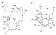
- Patent Document 1 Japanese Patent Application Laid-Open No. 2006-312409 (Patent Document 1), an electric wire 101 connecting a battery and an inverter is inserted into a metal pipe 102 to form a pipe harness 100, and the pipe harness 100 is interposed via a bracket 103 shown in FIG. It is attached to the vehicle body 104 (lower surface of the floor panel).
- the bracket 103 protrudes the arm portion 103b from the cylindrical portion 103a that is externally fitted to the metal pipe 102, and protrudes the plate-like attachment portion 103c laterally from the upper end of the arm portion 103b, and tightens the attachment portion 103c with bolts. It is fixed to the vehicle body 104 by welding.
- Patent Document 2 proposes a clamp (holding tool) for attaching a pipe to a vehicle body.
- the clamp 106 made of a resin molded product includes a clamp portion 107 having a receiving recess 107a for receiving the pipe 105, and a lid for closing the opening of the receiving recess 107a.
- the part 108 is connected by a hinge 109, and the clamp part 107 is provided with a fixing part 107d that is attached to a vehicle body (not shown).
- the lever piece 108 c provided on the lid part 108 is attached to the clamp part 107.
- the structure is such that the inner diameter of the receiving recess 107a is reduced in contact with the provided lever piece receiving portion 107c. With this structure, the pipe 105 accommodated in the receiving recess 107a of the clamp part 107 is firmly held, and displacement of the pipe 105 is prevented.
- the inner diameter of the cylindrical portion 103a in the bracket 103 of Patent Document 1 is set to a predetermined value according to the outer diameter size of the metal pipe 102 to be inserted.
- the inner diameter of the receiving recess 107a when the lid 108 is closed is set to a predetermined value according to the outer diameter size of the pipe 105 to be inserted.
- the pipes 102 and 105 inserted through the bracket 103 and the clamp 106 have different outer diameters within a predetermined tolerance range even if the pipes have the same outer diameter size. is there.
- bracket 103 and the clamp 106 are not structured to absorb the outer diameter tolerance, when the pipes 102 and 105 having an outer diameter close to the allowable lower limit value are inserted into the bracket 103 and the clamp 106 having the above configuration, the pipes 102 and 105 are inserted. In some cases, a gap is formed between the inner peripheral surface of the bracket 103 or the clamp 106 through which the pipe is inserted and the outer peripheral surface of the pipes 102 and 105, and the pipes 102 and 105 may vibrate or generate noise.
- the object of the present invention is to absorb the outer diameter tolerance of the metal pipe inserted into the clamp and prevent the metal pipe from vibrating or generating abnormal noise.
- the present invention is a clamp made of a resin molded product that attaches a pipe harness passing through an electric wire into a metal pipe to a vehicle body, A first part and a second part having a pair of semicircular inner surfaces are connected by a thin-walled hinge, and a locking part and a locked part to be locked to each other are provided on the divided end sides of the first and second parts, The metal pipe inserted between the semicircular inner surfaces of the first and second parts is sandwiched, and A mounting hole for inserting and locking the mounting material protruding from the vehicle body is provided in the first portion, an opening is provided in a part of the partitioning portion between the mounting hole and the semicircular inner surface, and a partitioning portion surrounding the opening is provided.
- a swing piece protrudes from a part of the peripheral surface into the opening, a mounting member contact protrusion is provided on one surface of the swing piece, and a crushing rib is provided on the other surface,
- the attachment material contact protrusion is pushed, the crushing rib protrudes from the semicircular inner surface side, and the metal pipe is inserted along the semicircular inner surface. The crushing rib is pressed against the metal pipe to fix the metal pipe.
- the clamp that connects the first and second portions having a pair of semicircular inner surfaces with thin-walled hinges and inserts and clamps the metal pipe of the pipe harness between the pair of semicircular inner surfaces
- An opening is provided in the partition part between the mounting hole of the first part for inserting and locking the protruding mounting material and the semicircular inner surface, and the swing piece is inserted into the opening from a part of the peripheral surface of the partition part surrounding the opening. It is protruding.
- the swinging piece is provided with a mounting material contact protrusion on one surface that contacts and presses the mounting material on the vehicle body side when the mounting material on the vehicle body is inserted and locked in the mounting hole, and a crushing rib projects on the other surface.
- the outer diameter of the metal pipe is the allowable lower limit value.
- the mounting material presses the mounting material contact protrusion of the swing piece to cause the crushing rib to protrude toward the semicircular inner surface, and the crushing rib is pressed against the metal pipe. Allows the metal pipe to be securely fixed in the clamp.
- the rocking piece pressed by the mounting member on the vehicle body swings in accordance with the outer diameter of the metal pipe in the clamp, and the crushing rib is brought into close contact with the metal pipe. It is possible to easily absorb the outer diameter tolerance of the metal pipe and prevent the vibration of the metal pipe and the generation of abnormal noise. Since the load on the clamp can be reduced by preventing the vibration of the metal pipe, the breakage of the clamp can also be prevented.
- the metal pipe can be fixed in the clamp without pressing by pressing the crushing rib of the swing piece, the diameter of the pair of semicircular inner surfaces of the first and second portions is larger than the outer diameter of the inserted metal pipe. Can be set larger. Therefore, until the mounting material protruding from the vehicle body is inserted and locked in the mounting hole of the clamp, the clamp position can be changed by moving the clamp freely in the axial direction of the metal pipe according to the layout of each vehicle body. The position of the clamp can be determined by inserting and locking the mounting material in the mounting hole of the clamp.
- the swing piece preferably protrudes from a part of the peripheral surface of the partition portion surrounding the opening via a hinge in order to facilitate swinging.
- the opening has a rectangular shape, and the swinging piece protrudes from the peripheral surface of the partition portion surrounding the opening at a position near the insertion direction of the mounting material inserted and locked in the mounting hole via a hinge. It is preferable that
- the mounting material protruding from the vehicle body is a stud bolt, and a locking piece that locks into the groove of the stud bolt protrudes from the inner surface of the mounting hole, and the outer periphery of the stud bolt that is inserted into the mounting hole It is preferable that the mounting member contact protrusion of the swing piece is pressed.
- the mounting material protruding from the vehicle body is a bracket with a locking hole, and a locking claw that is inserted and locked into the locking hole is provided on the inner surface of the mounting hole in a shape that allows the bracket to be inserted. It is good also as a setting by which the attachment material contact protrusion of the said rocking
- the crushing ribs provided on the rocking piece protrude in parallel from the substrate of the rocking piece, and each of the plurality of crushing ribs protrudes in a V shape toward the tip, and the tip is crushed by the pressed metal pipe. It is preferable that the setting is made.
- the tip of the crushing rib can be easily crushed and the adhesion to the metal pipe can be improved.
- the outline line at the tip of the plurality of crushing ribs is formed in an arc shape so as to be in close contact with the arc-shaped outer peripheral line of the metal pipe.
- the protruding amount of the crushing rib is such that the crushing rib is pressed against the metal pipe even when the outer diameter of the metal pipe inserted between the pair of semicircular inner surfaces of the first and second parts is an allowable lower limit value. It is preferable that the protrusion protrudes to the extent that it can be fixed.
- the locked portion made of a lock frame is provided on both side surfaces of the split end of the first portion, and the lock claw that is inserted and locked into the lock frame on both side surfaces of the split end of the second portion. It is preferable to provide a locking portion.
- the clamp preferably attaches the pipe harness piped under the floor in a hybrid vehicle or an electric vehicle to the lower surface of the floor panel, and the electric wire of the pipe harness connects between the battery and the inverter or between the inverter and the motor. It is preferable that
- the first and second portions having a pair of semicircular inner surfaces are connected by a thin hinge, and the metal pipe of the pipe harness is inserted and clamped between the pair of semicircular inner surfaces.
- an opening is provided in the partition portion between the mounting hole of the first portion for inserting and locking the mounting material protruding from the vehicle body and the semicircular inner surface, and the swing piece is formed from a part of the peripheral surface of the partition portion surrounding the opening. Is configured to project in the opening.
- the mounting material contact projections that contact and press the mounting material are provided on one surface of the swinging piece, and the crushing rib is provided on the other surface.
- the outer diameter of the metal pipe is the allowable lower limit value.
- the mounting material presses the mounting material contact protrusion of the swing piece to cause the crushing rib to protrude toward the semicircular inner surface, and the crushing rib is pressed against the metal pipe. Allows the metal pipe to be securely fixed in the clamp.
- the rocking piece pressed by the mounting member on the vehicle body swings in accordance with the outer diameter of the metal pipe in the clamp, and the crushing rib is brought into close contact with the metal pipe. It is possible to easily absorb the outer diameter tolerance of the metal pipe and prevent the vibration of the metal pipe and the generation of abnormal noise. Since the load on the clamp can be reduced by preventing the vibration of the metal pipe, the breakage of the clamp can also be prevented.
- FIG. 1st Embodiment It is a perspective view which shows the clamp of 1st Embodiment, (A) shows the state which open
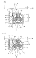
- (A) is a cross-sectional view taken along the line AA showing a state where the stud bolt is being inserted into the mounting hole of the clamp, and (B) is a state where the insertion locking of the stud bolt into the mounting hole of the clamp is completed.
- FIG. It is a principal part enlarged view of a rocking
- the clamp of 2nd Embodiment is shown, (A) is a perspective view of the state which is going to insert a bracket in the attachment hole of a clamp, (B) is a top view of a clamp. It is drawing which shows a prior art example. A prior art example is shown, (A) is sectional drawing of the state which opened the cover part, (B) is sectional drawing of the state which closed the cover part.
- FIG. 1 to 3 show a first embodiment.
- a battery of a hybrid vehicle and an inverter (not shown) are connected by three electric wires 1, and the electric wire 1 is inserted into a metal pipe 2 made of an aluminum-based metal to form a pipe harness 3.
- the pipe harness 3 is attached to the lower surface of the floor panel 30 of the vehicle body via the clamp 10.
- the clamp 10 made of a resin molded product is formed from a first portion 11 and a second portion 12 having semicircular inner surfaces 11a and 12a, respectively.
- the one end side of 12 is connected with the thin hinge 13 so that opening and closing is possible.
- a locked portion 14 and a locking portion 15 that are locked to each other are provided on both side surfaces of the divided end side that is the other end side of the first and second portions 11 and 12, respectively.
- the locked portion 14 provided in the first portion 11 is formed from a lock frame
- the locking portion 15 provided in the second portion 12 is a locking claw that is locked to the locked portion 14 formed of the lock frame.
- the pipe harness 3 is inserted between the pair of semicircular inner surfaces 11a, 12a of the first and second portions 11, 12, and the second portion is engaged with the locked portion 14 of the first portion 11.
- the pipe harness 3 is clamped by the clamp 10 by locking the locking portion 15 of the portion 12.
- the clamp 10 through which the pipe harness 3 is inserted and sandwiched is fixed to a mounting member protruding from the lower surface of the floor panel 30.
- the clamp 10 is welded from the lower surface of the floor panel 30.
- the stud bolt 31 protruded by is used as a mounting material.
- Mounting holes 16 and 17 for inserting and locking the stud bolt 31 are provided at the center position on the divided end side of the first and second portions 11 and 12.
- the divided end side of the second portion 12 disposed to face the lower surface of the floor panel 30 is flat, and the mounting hole 17 of the second portion 12 is circular according to the cross-sectional shape of the stud bolt 31.
- a pair of locking pieces 25 that are locked to the groove 32 of the stud bolt 31 from the inner peripheral surface of the mounting hole 17 are provided so as to face each other.
- the mounting hole 16 of the first portion 11 is a rectangular parallelepiped mounting hole communicating with the mounting hole 17 of the second portion 12, and is a part of the partition portion 18 that partitions the mounting hole 16 and the semicircular inner surface 11 a.
- a rectangular opening 19 is provided in the part.
- a swing piece 20 protrudes into the opening 19 via a hinge 24 on a peripheral surface 18 a at a position in front of the stud bolt 31 insertion direction.
- the substrate 21 of the swing piece 20 is provided with a mounting material contact protrusion 22 on one surface and a plurality of crushing ribs 23 protruding in parallel on the other surface.
- the attachment material contact protrusion 22 is protruded toward the attachment hole 16 so as to be pressed by the outer peripheral surface of the stud bolt 31 inserted into the attachment hole 16.
- a plurality of parallel crushing ribs 23 project toward the semicircular inner surface 11a, and the crushing ribs 23 are formed on the pair of semicircular inner surfaces 11a and 12a. It is pressed against the metal pipe 2 of the pipe harness 3 inserted between them.
- the plurality of parallel crushing ribs 23 are protruded in a V shape from the substrate 21 toward the front end, and the front ends of the crushing ribs 23 are easily crushed by the pressed metal pipe 2.
- the outer shape line at the tip of the crushing rib 23 is formed in an arc shape so as to be in close contact with the arcuate outer peripheral line of the metal pipe 2, and the protruding amount of the crushing rib 23 is between the pair of semicircular inner surfaces 11a and 12a. Even if the outer diameter of the inserted metal pipe 2 is an allowable lower limit, the crushing rib 23 is pressed against the metal pipe 2 so that the metal pipe 2 can be fixed without looseness.
- the first portion 11 arranged to face the road surface is provided with a drain hole 11b.
- clamps 10 shown in FIG. 1 are attached to predetermined positions of the pipe harness 3 piped on the lower surface of the floor panel 30 with a gap.
- the pipe harness 3 is arranged on the semicircular inner surface 11a of the first portion 11 of the clamp 10 in the opened state as shown in FIG. 1A, and the first and second are as shown in FIG.
- the portions 11 and 12 are closed, and the locking portion (locking claw) 15 of the second portion 12 is locked to the locked portion (lock frame) 14 of the first portion 11.
- the pipe harness 3 is inserted and sandwiched between the pair of semicircular inner surfaces 11a and 12a.
- the stud bolt 31 protruded from the lower surface of the floor panel 30 is inserted and locked into the mounting holes 17 and 16 of the second and first portions 12 and 11 of the clamp 10 through which the pipe harness 3 is inserted.
- the mounting material contact protrusion 22 of the swing piece 20 that protrudes toward the mounting hole 16 is pushed by the outer peripheral surface of the stud bolt 31 as shown in FIG.
- the crushing rib 23 protrudes toward the semicircular inner surface 11a.
- the crushing rib 23 is pressed against the metal pipe 2 of the pipe harness 3 as shown in FIG. 2B, and the metal pipe 2 is fixed in the clamp 10.
- the outer diameter tolerance of the metal pipe 2 inserted between the pair of semicircular inner surfaces 11a, 12a of the first and second portions 11, 12 is relatively large. Even if it is the allowable lower limit value, just by inserting and locking the stud bolt 31 into the mounting holes 16 and 17, the outer peripheral surface of the stud bolt 31 presses the mounting material contact projection 22 of the swing piece 20 and the crushing rib.
- the metal pipe 2 can be firmly fixed in the clamp 10 by projecting 23 toward the semicircular inner surface 11 a and pressing the crushing rib 23 against the metal pipe 2.
- the swinging piece 20 pressed by the stud bolt 31 swings in accordance with the outer diameter of the metal pipe 2 so that the crushing rib 23 is in close contact with the metal pipe 2.
- the outer diameter tolerance of the metal pipe 2 can be easily absorbed to prevent the metal pipe 2 from vibrating or generating abnormal noise. Since the load on the clamp 10 can be reduced by preventing the vibration of the metal pipe 2, the breakage of the clamp 10 can also be prevented.
- the diameter of the pair of semicircular inner surfaces 11a and 12a of the first and second portions 11 and 12 is as follows. It can be set larger than the outer diameter of the metal pipe 2. Therefore, until the stud bolt 31 is inserted and locked in the mounting holes 17 and 16 of the clamp 10, the position of the clamp 10 can be changed by freely moving the clamp 10 in the axial direction of the metal pipe 2 according to the layout of each vehicle body. The position of the clamp 10 can be determined by inserting and locking the stud bolt 31 into the mounting holes 17 and 16 of the clamp 10.
- FIG. 4 shows a second embodiment.
- the mounting material protruding from the floor panel 30 is a bracket 51 as shown in FIG.
- the bracket 51 has a U-shaped cross section having a flat central portion 51a.
- the mounting hole 47 of the second portion 12 of the clamp 10 has a shape into which the bracket 51 can be inserted, and the mounting hole 46 of the first portion 11 communicating with the mounting hole 47 of the second portion has a rectangular parallelepiped shape as in the first embodiment. It is said.
- a locking hole 52 is provided in the central portion 51 a of the bracket 51, and a locking claw 48 that is inserted and locked into the locking hole 52 is provided on the inner surface of the first portion mounting hole 46. Further, when the bracket 51 is inserted into the mounting hole 46 of the first portion, the outer surface of the central portion 51a presses the mounting member contact protrusion (not shown) of the swing piece. Other points are the same as in the first embodiment.
- the rocking piece pressed against the outer surface of the central portion 51a of the bracket 51 rocks in accordance with the outer diameter of the metal pipe 2 to bring the crushing rib into close contact with the metal pipe 2.
- the outer diameter tolerance of 2 can be easily absorbed, and the occurrence of vibration and abnormal noise of the metal pipe 2 can be prevented.
Landscapes
- Engineering & Computer Science (AREA)
- Mechanical Engineering (AREA)
- General Engineering & Computer Science (AREA)
- Architecture (AREA)
- Civil Engineering (AREA)
- Structural Engineering (AREA)
- Supports For Pipes And Cables (AREA)
- Clamps And Clips (AREA)
- Installation Of Indoor Wiring (AREA)
Abstract
Description
一対の半円状内面を有する第1部分と第2部分を薄肉ヒンジで連結すると共に、該第1、第2部分の分割端側に互いに係止する係止部と被係止部を設け、該第1、第2部分の半円状内面の間に挿通する前記金属パイプを挟持する構成とし、かつ、
前記第1部分に車体から突出する取付材を挿入係止する取付穴を設け、該取付穴と前記半円状内面との仕切部の一部に開口を設けると共に、該開口を囲む仕切部の周面の一部から揺動片を該開口内に突設し、前記揺動片の一面に取付材接触突起を設けると共に他面に潰しリブを突設し、
前記取付穴に前記取付材が挿入されると前記取付材接触突起が押されて前記半円状内面側に前記潰しリブを突出させ、該半円状内面に沿って挿通している前記金属パイプに前記潰しリブが押し付けられて金属パイプを固定する構成としていることを特徴とするクランプを提供している。
したがって、前記第1、第2部分の一対の半円状内面の間に挿通する金属パイプの外径公差が比較的大きく該金属パイプの外径がその許容下限値であっても、車体側の取付材を取付穴に挿入係止するだけで該取付材が揺動片の取付材接触突起を押圧して潰しリブを半円状内面側に突出させ、該潰しリブが金属パイプに押し付けられることによって金属パイプをクランプ内にしっかりと固定することができる。
また、前記複数の潰しリブの先端の外形ラインは、金属パイプの円弧状の外周ラインに密着させるために円弧状としておくことが好ましい。
前記潰しリブの突出量は、第1、第2部分の一対の半円状内面の間に挿通する金属パイプの外径が許容下限値であっても該金属パイプに潰しリブを押し付けて金属パイプを固定できる程度に突出させておくことが好ましい。
図1乃至図3は第1実施形態を示す。本実施形態では、ハイブリッド自動車のバッテリとインバータ(図示せず)とを3本の電線1で接続しており、該電線1をアルミニウム系金属からなる金属パイプ2に挿通してパイプハーネス3を形成し、該パイプハーネス3を車体のフロアパネル30の下面にクランプ10を介して取り付けている。
フロアパネル30の下面に対向配置される第2部分12の分割端側は平板状とし第2部分12の取付穴17はスタッドボルト31の断面形状に合わせた円形状としている。また、取付穴17の内周面からスタッドボルト31の溝32に係止する一対の係止片25を対向して突設している。
一方、第1部分11の取付穴16は、前記第2部分12の取付穴17に連通した直方体形状の取付穴であり、該取付穴16と半円状内面11aとを仕切る仕切部18の一部に矩形状の開口19を設けている。該開口19を囲む仕切部18の周面のうち、スタッドボルト31挿入方向の手前位置の周面18aに、ヒンジ24を介して揺動片20を開口19内に突設している。
まず、フロアパネル30の下面に配管するパイプハーネス3の所定位置に図1に示すクランプ10を間隔をあけて5~7個取り付ける。具体的には、図1(A)のような開放状態のクランプ10の第1部分11の半円状内面11aにパイプハーネス3を配置し、図1(B)のように第1、第2部分11、12を閉鎖して第1部分11の被係止部(ロック枠)14に第2部分12の係止部(係止爪)15を係止させる。これにより、パイプハーネス3が一対の半円状内面11a、12aの間に挿通、挟持された状態となる。
第2実施形態では、フロアパネル30から突出する取付材を図4に示すようなブラケット51としている。ブラケット51は平板状の中央部51aを有する断面コ字状としている。また、クランプ10の第2部分12の取付穴47はブラケット51を挿入できる形状とし、第2部分の取付穴47に連通する第1部分11の取付穴46は第1実施形態と同様、直方体形状としている。ブラケット51の中央部51aには係止穴52を設け、第1部分の取付穴46の内面には、前記係止穴52に挿入係止する係止爪48を突設している。また、ブラケット51が第1部分の取付穴46に挿入されると、中央部51aの外面が揺動片の取付材接触突起(図示せず)を押圧する構成としている。その他の点は第1実施形態と同様としている。
2 金属パイプ
3 パイプハーネス
10 クランプ
11 第1部分
12 第2部分
11a、12a 半円状内面
13 薄肉ヒンジ
14 被係止部
15 係止部
16、17、46、47 取付穴
18 仕切部
19 開口
20 揺動片
21 基板
22 取付材接触突起
23 潰しリブ
25 係止片
48 係止爪
30 フロアパネル
31 スタッドボルト
32 溝
51 ブラケット
52 係止穴
Claims (6)
- 金属パイプ内に電線を挿通しているパイプハーネスを車体に取り付ける樹脂成形品からなるクランプであって、
一対の半円状内面を有する第1部分と第2部分を薄肉ヒンジで連結すると共に、該第1、第2部分の分割端側に互いに係止する係止部と被係止部を設け、該第1、第2部分の半円状内面の間に挿通する前記金属パイプを挟持する構成とし、かつ、
前記第1部分に車体から突出する取付材を挿入係止する取付穴を設け、該取付穴と前記半円状内面との仕切部の一部に開口を設けると共に、該開口を囲む仕切部の周面の一部から揺動片を該開口内に突設し、前記揺動片の一面に取付材接触突起を設けると共に他面に潰しリブを突設し、
前記取付穴に前記取付材が挿入されると前記取付材接触突起が押されて前記半円状内面側に前記潰しリブを突出させ、該半円状内面に沿って挿通している前記金属パイプに前記潰しリブが押し付けられて金属パイプを固定する構成としていることを特徴とするクランプ。 - 前記車体から突出する取付材はスタッドボルトであり、前記取付穴の内面から前記スタッドボルトの溝に係止する係止片が突設され、該取付穴に挿入する前記スタッドボルトの外周面で前記揺動片の取付材接触突起が押される設定としている請求項1に記載のクランプ。
- 前記車体から突出する取付材は係止穴をあけたブラケットであり、該ブラケットを挿入できる形状とした前記取付穴の内面に前記係止穴に挿入係止する係止爪を突設し、該取付穴に挿入する前記ブラケットの外面で前記揺動片の取付材接触突起が押される設定としている請求項1に記載のクランプ。
- 前記揺動片に設ける前記潰しリブは、該揺動片の基板から並列状に突出し、これら複数の潰しリブはそれぞれ先端に向けてV字状に突出し、押し当てられる前記金属パイプにより先端が潰される設定としている請求項1乃至請求項3のいずれか1項に記載のクランプ。
- 前記第1部分の分割端の両側面にロック枠からなる前記被係止部を設けていると共に、前記第2部分の分割端の両側面に前記ロック枠に挿入係止するロック爪からなる前記係止部を設けている請求項1乃至請求項4のいずれか1項に記載のクランプ。
- ハイブリッド自動車または電気自動車において床下に配管される前記パイプハーネスをフロアパネルの下面に取り付けるものである請求項1乃至請求項5のいずれか1項に記載のクランプ。
Priority Applications (3)
| Application Number | Priority Date | Filing Date | Title |
|---|---|---|---|
| US14/236,983 US8979039B2 (en) | 2011-09-08 | 2012-02-23 | Clamp |
| DE112012003735.9T DE112012003735T5 (de) | 2011-09-08 | 2012-02-23 | Schelle |
| CN201280037942.6A CN103718402A (zh) | 2011-09-08 | 2012-02-23 | 夹子 |
Applications Claiming Priority (2)
| Application Number | Priority Date | Filing Date | Title |
|---|---|---|---|
| JP2011195627A JP5729225B2 (ja) | 2011-09-08 | 2011-09-08 | クランプ |
| JP2011-195627 | 2011-09-08 |
Publications (1)
| Publication Number | Publication Date |
|---|---|
| WO2013035355A1 true WO2013035355A1 (ja) | 2013-03-14 |
Family
ID=47831822
Family Applications (1)
| Application Number | Title | Priority Date | Filing Date |
|---|---|---|---|
| PCT/JP2012/054358 Ceased WO2013035355A1 (ja) | 2011-09-08 | 2012-02-23 | クランプ |
Country Status (5)
| Country | Link |
|---|---|
| US (1) | US8979039B2 (ja) |
| JP (1) | JP5729225B2 (ja) |
| CN (1) | CN103718402A (ja) |
| DE (1) | DE112012003735T5 (ja) |
| WO (1) | WO2013035355A1 (ja) |
Cited By (2)
| Publication number | Priority date | Publication date | Assignee | Title |
|---|---|---|---|---|
| EP2940659A1 (fr) * | 2014-05-01 | 2015-11-04 | Automatisme et Techniques Avancees | Boitier électronique de taximetre comportant des moyens de connexion multiple |
| US9920858B2 (en) | 2015-06-30 | 2018-03-20 | Cnh Industrial America Llc | Mounting device for tubular elements |
Families Citing this family (32)
| Publication number | Priority date | Publication date | Assignee | Title |
|---|---|---|---|---|
| JP5704195B2 (ja) * | 2013-07-01 | 2015-04-22 | 株式会社オートネットワーク技術研究所 | プロテクタおよびプロテクタ付きワイヤーハーネス |
| FR3015625B1 (fr) * | 2013-12-20 | 2015-12-11 | Snecma | Bras de guidage d'elements de forme allongee, en particulier pour une turbomachine |
| US9653901B2 (en) * | 2014-10-22 | 2017-05-16 | Daiwa Kasei Industry Co., Ltd. | Holding component for vehicle |
| EP3015317B1 (de) * | 2014-10-30 | 2018-12-05 | Nexans | Anordnung zum Befestigen eines langgestreckten Gegenstands in einem Kraftfahrzeug |
| DE102015007630A1 (de) * | 2015-06-15 | 2016-12-15 | GM Global Technology Operations LLC (n. d. Ges. d. Staates Delaware) | Kabelsatzhalter für ein Kraftfahrzeug sowie Kraftfahrzeug mit Kabelsatzhalter |
| US20170063064A1 (en) | 2015-08-24 | 2017-03-02 | William Gary Gintz | Releasable holder for cables and conduit |
| US20190267785A1 (en) | 2015-08-24 | 2019-08-29 | Sticnstac, LLC | Releasable holder for cables and conduit |
| JP6551216B2 (ja) * | 2015-12-18 | 2019-07-31 | 住友電装株式会社 | クリップ装置 |
| US10903632B2 (en) | 2016-02-05 | 2021-01-26 | Hellermanntyton Corporation | Adjustable P-clamp with multiple mounting options |
| JP6524934B2 (ja) * | 2016-02-08 | 2019-06-05 | 住友電装株式会社 | プロテクタ |
| US10253914B2 (en) * | 2016-07-21 | 2019-04-09 | Ford Global Technologies, Llc | Clip having positive installation indicator for securing fuel line to foam part |
| CN106169723A (zh) * | 2016-07-29 | 2016-11-30 | 天津德芃科技集团有限公司 | 一种电线电缆束的保护装置 |
| JP6780990B2 (ja) * | 2016-09-15 | 2020-11-04 | 大和化成工業株式会社 | ブラケット組付け構造 |
| JP6724763B2 (ja) * | 2016-12-19 | 2020-07-15 | 住友電装株式会社 | ワイヤハーネス |
| US10186851B2 (en) * | 2017-06-27 | 2019-01-22 | Aptiv Technologies Limited | Cable-assembly for robotic installation |
| WO2019107291A1 (ja) * | 2017-11-29 | 2019-06-06 | 住友電装株式会社 | ブラケット付き導電路 |
| US10903633B2 (en) * | 2018-06-07 | 2021-01-26 | Panduit Corp. | Interlocking cable cleat |
| JP7176725B2 (ja) * | 2018-07-20 | 2022-11-22 | 日本光機工業株式会社 | 非常用標識灯 |
| US10927977B2 (en) * | 2018-08-28 | 2021-02-23 | Ofs Fitel, Llc | Concealed safety fasteners for communication lines |
| JP2021055688A (ja) * | 2019-09-27 | 2021-04-08 | 有限会社アールストーン | 配線・配管吊下支持具 |
| JP2021055689A (ja) * | 2019-09-27 | 2021-04-08 | 有限会社アールストーン | 配線・配管吊下支持具 |
| JP2021055687A (ja) * | 2019-09-27 | 2021-04-08 | 有限会社アールストーン | 配線・配管吊下支持具 |
| JP7314790B2 (ja) * | 2019-12-19 | 2023-07-26 | 住友電装株式会社 | プロテクタ及びワイヤハーネス |
| USD969599S1 (en) * | 2020-02-14 | 2022-11-15 | Mario Brosche | Fastening clip |
| US11685021B2 (en) * | 2021-03-31 | 2023-06-27 | Don Herrod | Trapdoor clamp |
| DE102021112778A1 (de) | 2021-05-18 | 2022-11-24 | Bayerische Motoren Werke Aktiengesellschaft | Halter zur Aufnahme einer Leitung, Befestigungsanordnung zur Befestigung einer Leitung an einem Kraftfahrzeug und Verfahren zur Befestigung einer Leitung an einem Kraftfahrzeug |
| JP2023078919A (ja) * | 2021-11-26 | 2023-06-07 | 住友電装株式会社 | ワイヤハーネス |
| US12326210B2 (en) | 2022-03-24 | 2025-06-10 | Hellermanntyton Corporation | Quick attach clamp |
| JP2023148991A (ja) * | 2022-03-30 | 2023-10-13 | 住友電装株式会社 | クランプ |
| US12338848B2 (en) | 2022-06-30 | 2025-06-24 | Hellermanntyton Corporation | Anti-wobble fir tree mount |
| DE202023100903U1 (de) * | 2023-02-24 | 2024-05-27 | WAGO Verwaltungsgesellschaft mit beschränkter Haftung | Kabelschelle und elektrische Einrichtung mit einer Kabelschelle |
| US20240360922A1 (en) | 2023-04-28 | 2024-10-31 | Hellermanntyton Corporation | Cable Tie Cradle Mount Fixings |
Citations (4)
| Publication number | Priority date | Publication date | Assignee | Title |
|---|---|---|---|---|
| JPS6436709U (ja) * | 1987-08-29 | 1989-03-06 | ||
| JP2001056070A (ja) * | 1999-08-16 | 2001-02-27 | Sumitomo Wiring Syst Ltd | ブラケット係止用クランプ |
| JP2007143309A (ja) * | 2005-11-18 | 2007-06-07 | Sumitomo Wiring Syst Ltd | ワイヤハーネス用クランプ |
| JP2011085164A (ja) * | 2009-10-14 | 2011-04-28 | Hellermann Tyton Co Ltd | クランプ |
Family Cites Families (21)
| Publication number | Priority date | Publication date | Assignee | Title |
|---|---|---|---|---|
| US4550891A (en) * | 1982-10-15 | 1985-11-05 | Usm Corporation | Plastic pipe clip |
| JPH0788522B2 (ja) | 1987-07-31 | 1995-09-27 | 新日本製鐵株式会社 | 高炉操業方法 |
| US4842237A (en) * | 1988-11-23 | 1989-06-27 | Phillips Plastics Corporation | One-piece wire retainer clip mountable on threaded stud |
| US5390876A (en) * | 1993-11-19 | 1995-02-21 | Sumitomo Denso Kabushiki Kaisha | Holder for fixing wiring harness and the like to automobile body |
| US5494245A (en) * | 1994-05-04 | 1996-02-27 | Yazaki Corporation | Wiring harness retainer clip |
| US5803413A (en) * | 1996-11-21 | 1998-09-08 | Avery Dennison Corporation | Cable tie having a stud mountable fastener |
| JPH1113941A (ja) * | 1997-06-19 | 1999-01-22 | Sumitomo Wiring Syst Ltd | ブラケット係止用のクランプ |
| US6915990B2 (en) * | 2001-05-29 | 2005-07-12 | Newfrey Llc | Pipe holding fastener |
| JP3695354B2 (ja) * | 2001-06-08 | 2005-09-14 | 住友電装株式会社 | ワイヤハーネス用のクランプ |
| JP2003214559A (ja) * | 2002-01-22 | 2003-07-30 | Nifco Inc | クランプ、および管状物の固定方法 |
| US7320571B2 (en) * | 2002-08-01 | 2008-01-22 | Newfrey Llc | Device for mounting a component such as a pipe on a stud |
| JP4002812B2 (ja) * | 2002-10-08 | 2007-11-07 | 株式会社ニフコ | クランプ |
| DE10306904C5 (de) * | 2003-02-18 | 2012-05-03 | Itw Automotive Products Gmbh & Co. Kg | Halteelement |
| US7162790B1 (en) * | 2004-06-01 | 2007-01-16 | David Orlen Daniels | Fastener and method for supporting elongated material |
| JP4787535B2 (ja) | 2005-05-09 | 2011-10-05 | 株式会社オートネットワーク技術研究所 | シールド導電体の取付け構造 |
| JP2009503375A (ja) * | 2005-07-20 | 2009-01-29 | ニューフレイ リミテッド ライアビリティ カンパニー | リテーナを有するヒンジ付クリップ |
| JP4976708B2 (ja) * | 2006-03-06 | 2012-07-18 | 住友電装株式会社 | 取付具 |
| JP2008141822A (ja) | 2006-11-30 | 2008-06-19 | Nippon Pop Rivets & Fasteners Ltd | パイプ等の長尺部材の保持具 |
| JP5140414B2 (ja) * | 2007-12-28 | 2013-02-06 | 住友電装株式会社 | コルゲートクランプ |
| JP5602460B2 (ja) * | 2010-03-05 | 2014-10-08 | 株式会社ニフコ | クランプ |
| EP2577141A4 (en) * | 2010-05-26 | 2016-05-11 | Scot Kennedy | SUPPORT ATTACHMENT FOR FASTENING TO A SUPERIOR THREADED JOINT BY EXTRUSION |
-
2011
- 2011-09-08 JP JP2011195627A patent/JP5729225B2/ja not_active Expired - Fee Related
-
2012
- 2012-02-23 WO PCT/JP2012/054358 patent/WO2013035355A1/ja not_active Ceased
- 2012-02-23 US US14/236,983 patent/US8979039B2/en not_active Expired - Fee Related
- 2012-02-23 CN CN201280037942.6A patent/CN103718402A/zh active Pending
- 2012-02-23 DE DE112012003735.9T patent/DE112012003735T5/de not_active Withdrawn
Patent Citations (4)
| Publication number | Priority date | Publication date | Assignee | Title |
|---|---|---|---|---|
| JPS6436709U (ja) * | 1987-08-29 | 1989-03-06 | ||
| JP2001056070A (ja) * | 1999-08-16 | 2001-02-27 | Sumitomo Wiring Syst Ltd | ブラケット係止用クランプ |
| JP2007143309A (ja) * | 2005-11-18 | 2007-06-07 | Sumitomo Wiring Syst Ltd | ワイヤハーネス用クランプ |
| JP2011085164A (ja) * | 2009-10-14 | 2011-04-28 | Hellermann Tyton Co Ltd | クランプ |
Cited By (3)
| Publication number | Priority date | Publication date | Assignee | Title |
|---|---|---|---|---|
| EP2940659A1 (fr) * | 2014-05-01 | 2015-11-04 | Automatisme et Techniques Avancees | Boitier électronique de taximetre comportant des moyens de connexion multiple |
| FR3020702A1 (fr) * | 2014-05-01 | 2015-11-06 | Automatisme Et Tech Avancees Ata | Boitier electronique de taximetre comportant des moyens de connexion multiple |
| US9920858B2 (en) | 2015-06-30 | 2018-03-20 | Cnh Industrial America Llc | Mounting device for tubular elements |
Also Published As
| Publication number | Publication date |
|---|---|
| JP5729225B2 (ja) | 2015-06-03 |
| US20140217244A1 (en) | 2014-08-07 |
| JP2013059188A (ja) | 2013-03-28 |
| DE112012003735T5 (de) | 2014-07-24 |
| CN103718402A (zh) | 2014-04-09 |
| US8979039B2 (en) | 2015-03-17 |
Similar Documents
| Publication | Publication Date | Title |
|---|---|---|
| JP5729225B2 (ja) | クランプ | |
| JP2019006182A (ja) | 車両下部構造 | |
| WO2013042387A1 (ja) | クランプ | |
| JP5405506B2 (ja) | バッテリ支持構造 | |
| JP2007320552A (ja) | 自動車用の自動車シャーシ | |
| JP5299698B2 (ja) | 電気接続箱 | |
| JP5299699B2 (ja) | 電気接続箱 | |
| WO2018131540A1 (ja) | ドアミラー | |
| WO2011052081A1 (ja) | スペアタイヤ内スピーカ装置の取り付け構造 | |
| JP6139109B2 (ja) | 電線保持構造 | |
| JP2011223650A (ja) | ハーネスプロテクタの固定構造 | |
| JP2010108785A (ja) | バッテリ接続端子保護カバー | |
| JP5182161B2 (ja) | ワイヤハーネス用クランプ | |
| JP7464648B2 (ja) | インストルメントパネル構造 | |
| KR101840462B1 (ko) | 버스바 고정용 스터드 클립 | |
| WO2022181802A1 (ja) | 車両用外装部品 | |
| JP6225056B2 (ja) | 電気接続箱 | |
| WO2018030335A1 (ja) | 車載部品 | |
| JP2017199630A (ja) | バスバー及び電気接続箱 | |
| WO2020137493A1 (ja) | 電子モジュール | |
| WO2020137494A1 (ja) | 電子モジュール | |
| CN103568804A (zh) | 电源安装结构和设有电源安装结构的车辆 | |
| KR200431599Y1 (ko) | 자동차용 부품의 진동방지구조 | |
| JP2026025153A (ja) | 電気接続箱 | |
| KR101840460B1 (ko) | 버스바 고정용 스터드 클립 |
Legal Events
| Date | Code | Title | Description |
|---|---|---|---|
| 121 | Ep: the epo has been informed by wipo that ep was designated in this application |
Ref document number: 12829448 Country of ref document: EP Kind code of ref document: A1 |
|
| WWE | Wipo information: entry into national phase |
Ref document number: 14236983 Country of ref document: US |
|
| WWE | Wipo information: entry into national phase |
Ref document number: 1120120037359 Country of ref document: DE Ref document number: 112012003735 Country of ref document: DE |
|
| 122 | Ep: pct application non-entry in european phase |
Ref document number: 12829448 Country of ref document: EP Kind code of ref document: A1 |