WO2007114168A1 - リチウム二次電池及びその製造方法 - Google Patents
リチウム二次電池及びその製造方法 Download PDFInfo
- Publication number
- WO2007114168A1 WO2007114168A1 PCT/JP2007/056655 JP2007056655W WO2007114168A1 WO 2007114168 A1 WO2007114168 A1 WO 2007114168A1 JP 2007056655 W JP2007056655 W JP 2007056655W WO 2007114168 A1 WO2007114168 A1 WO 2007114168A1
- Authority
- WO
- WIPO (PCT)
- Prior art keywords
- negative electrode
- key
- particles
- lithium secondary
- secondary battery
- Prior art date
- Legal status (The legal status is an assumption and is not a legal conclusion. Google has not performed a legal analysis and makes no representation as to the accuracy of the status listed.)
- Ceased
Links
Classifications
-
- H—ELECTRICITY
- H01—ELECTRIC ELEMENTS
- H01M—PROCESSES OR MEANS, e.g. BATTERIES, FOR THE DIRECT CONVERSION OF CHEMICAL ENERGY INTO ELECTRICAL ENERGY
- H01M10/00—Secondary cells; Manufacture thereof
- H01M10/05—Accumulators with non-aqueous electrolyte
- H01M10/058—Construction or manufacture
- H01M10/0587—Construction or manufacture of accumulators having only wound construction elements, i.e. wound positive electrodes, wound negative electrodes and wound separators
-
- H—ELECTRICITY
- H01—ELECTRIC ELEMENTS
- H01M—PROCESSES OR MEANS, e.g. BATTERIES, FOR THE DIRECT CONVERSION OF CHEMICAL ENERGY INTO ELECTRICAL ENERGY
- H01M4/00—Electrodes
- H01M4/02—Electrodes composed of, or comprising, active material
- H01M4/36—Selection of substances as active materials, active masses, active liquids
- H01M4/38—Selection of substances as active materials, active masses, active liquids of elements or alloys
-
- H—ELECTRICITY
- H01—ELECTRIC ELEMENTS
- H01M—PROCESSES OR MEANS, e.g. BATTERIES, FOR THE DIRECT CONVERSION OF CHEMICAL ENERGY INTO ELECTRICAL ENERGY
- H01M10/00—Secondary cells; Manufacture thereof
- H01M10/05—Accumulators with non-aqueous electrolyte
-
- H—ELECTRICITY
- H01—ELECTRIC ELEMENTS
- H01M—PROCESSES OR MEANS, e.g. BATTERIES, FOR THE DIRECT CONVERSION OF CHEMICAL ENERGY INTO ELECTRICAL ENERGY
- H01M4/00—Electrodes
- H01M4/02—Electrodes composed of, or comprising, active material
- H01M4/04—Processes of manufacture in general
-
- H—ELECTRICITY
- H01—ELECTRIC ELEMENTS
- H01M—PROCESSES OR MEANS, e.g. BATTERIES, FOR THE DIRECT CONVERSION OF CHEMICAL ENERGY INTO ELECTRICAL ENERGY
- H01M4/00—Electrodes
- H01M4/02—Electrodes composed of, or comprising, active material
- H01M4/13—Electrodes for accumulators with non-aqueous electrolyte, e.g. for lithium-accumulators; Processes of manufacture thereof
- H01M4/134—Electrodes based on metals, Si or alloys
-
- H—ELECTRICITY
- H01—ELECTRIC ELEMENTS
- H01M—PROCESSES OR MEANS, e.g. BATTERIES, FOR THE DIRECT CONVERSION OF CHEMICAL ENERGY INTO ELECTRICAL ENERGY
- H01M4/00—Electrodes
- H01M4/02—Electrodes composed of, or comprising, active material
- H01M4/62—Selection of inactive substances as ingredients for active masses, e.g. binders, fillers
-
- H—ELECTRICITY
- H01—ELECTRIC ELEMENTS
- H01M—PROCESSES OR MEANS, e.g. BATTERIES, FOR THE DIRECT CONVERSION OF CHEMICAL ENERGY INTO ELECTRICAL ENERGY
- H01M4/00—Electrodes
- H01M4/02—Electrodes composed of, or comprising, active material
- H01M2004/021—Physical characteristics, e.g. porosity, surface area
-
- Y—GENERAL TAGGING OF NEW TECHNOLOGICAL DEVELOPMENTS; GENERAL TAGGING OF CROSS-SECTIONAL TECHNOLOGIES SPANNING OVER SEVERAL SECTIONS OF THE IPC; TECHNICAL SUBJECTS COVERED BY FORMER USPC CROSS-REFERENCE ART COLLECTIONS [XRACs] AND DIGESTS
- Y02—TECHNOLOGIES OR APPLICATIONS FOR MITIGATION OR ADAPTATION AGAINST CLIMATE CHANGE
- Y02E—REDUCTION OF GREENHOUSE GAS [GHG] EMISSIONS, RELATED TO ENERGY GENERATION, TRANSMISSION OR DISTRIBUTION
- Y02E60/00—Enabling technologies; Technologies with a potential or indirect contribution to GHG emissions mitigation
- Y02E60/10—Energy storage using batteries
-
- Y—GENERAL TAGGING OF NEW TECHNOLOGICAL DEVELOPMENTS; GENERAL TAGGING OF CROSS-SECTIONAL TECHNOLOGIES SPANNING OVER SEVERAL SECTIONS OF THE IPC; TECHNICAL SUBJECTS COVERED BY FORMER USPC CROSS-REFERENCE ART COLLECTIONS [XRACs] AND DIGESTS
- Y02—TECHNOLOGIES OR APPLICATIONS FOR MITIGATION OR ADAPTATION AGAINST CLIMATE CHANGE
- Y02P—CLIMATE CHANGE MITIGATION TECHNOLOGIES IN THE PRODUCTION OR PROCESSING OF GOODS
- Y02P70/00—Climate change mitigation technologies in the production process for final industrial or consumer products
- Y02P70/50—Manufacturing or production processes characterised by the final manufactured product
-
- Y—GENERAL TAGGING OF NEW TECHNOLOGICAL DEVELOPMENTS; GENERAL TAGGING OF CROSS-SECTIONAL TECHNOLOGIES SPANNING OVER SEVERAL SECTIONS OF THE IPC; TECHNICAL SUBJECTS COVERED BY FORMER USPC CROSS-REFERENCE ART COLLECTIONS [XRACs] AND DIGESTS
- Y10—TECHNICAL SUBJECTS COVERED BY FORMER USPC
- Y10T—TECHNICAL SUBJECTS COVERED BY FORMER US CLASSIFICATION
- Y10T29/00—Metal working
- Y10T29/49—Method of mechanical manufacture
- Y10T29/49002—Electrical device making
- Y10T29/49108—Electric battery cell making
- Y10T29/49115—Electric battery cell making including coating or impregnating
Definitions
- Lithium secondary battery and manufacturing method thereof Lithium secondary battery and manufacturing method thereof
- the present invention relates to a lithium secondary battery and a method for producing the same.
- Lithium secondary batteries that charge and discharge as lithium ions move between the positive and negative electrodes along with charge and discharge are higher in energy density and higher than other secondary batteries such as nickel cadmium batteries. Because of its capacity, it is widely used as a drive power source for the above mobile communication devices.
- further improvements in the energy density and cycle characteristics of lithium secondary batteries have been demanded.
- the limit is 372mAhZg, which is an obstacle to the high capacity of the battery.
- Non-Patent Document 1 a lithium secondary battery using aluminum, silicon, or tin alloyed with lithium as a negative electrode active material having a high energy density per mass and per volume has been reported (see Non-Patent Document 1 below). ).
- silicon is promising as a negative electrode active material of a battery having a large theoretical capacity and a high capacity, and various lithium secondary batteries using this as a negative electrode active material have been proposed (the following patents). Reference 1).
- the negative electrode active material expands and contracts with charge / discharge, so that a new surface is formed on the surface of the negative electrode active material each time the charge / discharge is performed.
- the cycle characteristics of the battery are deteriorated and the battery thickness is increased due to the swelling of the negative electrode active material.
- Patent Document 1 Japanese Patent Laid-Open No. 10-255768
- Patent Document 2 WO2004Zl09839
- Patent Document 3 Japanese Patent Application Laid-Open No. 2004-319390
- Patent Document 4 Japanese Patent Application Laid-Open No. 2004-311429
- Non-Patent Document l Solid State Ionics, 113— 115, p57
- the present invention provides a lithium secondary battery that is excellent in cycle characteristics and can achieve high energy density even when using key particles or the like as a negative electrode active material, and a method for manufacturing the same. With the goal.
- the present invention provides a negative electrode active material layer including a negative electrode active material particle and a negative electrode binder including a key particle and Z or a key alloy particle, and is disposed on the surface of the negative electrode current collector.
- a lithium secondary battery comprising a negative electrode, a positive electrode, a separator, and a non-aqueous electrolyte, a crystal of the above-mentioned key particles and the key alloy particles (hereinafter sometimes referred to as key particles).
- the child size is less than lOOnm.
- the crystallite size is small! /, (Polycrystalline) silicon particles and the like as the negative electrode active material
- the crystallographic orientation is disordered (because the crystallographic orientation does not extend in a straight line like a single crystal)
- the crystallographic orientation does not extend in a straight line like a single crystal
- the key particles and the non-aqueous electrolyte react on the new surface, and the cycle characteristics of the battery are deteriorated or the expansion of the key particles and the like.
- the crystallite size of the silicon particles or the like to be less than lOOnm, the above-described effects can be further exerted.
- the crystallite size of the key particle or the like is less than lOOnm, the presence of many crystallites in the particle as described above causes many fine irregularities to exist on the surface of the key particle or the like. Exists. As described above, when the surface of the key particle or the like has fine irregularities, the negative electrode binder enters into the irregular part and the anchor effect is exhibited, so that the adhesion between the key particles and the like is further improved. The effect is also demonstrated.
- the crystallite size of the key particles and the key alloy particles is preferably 60 nm or less.
- the crystallite size of the key particle or the like is 60 nm or less, the crack of the key particle due to charging / discharging is further reduced, so that the increase in the contact area between the nonaqueous electrolyte and the new surface in the negative electrode active material can be further suppressed. At the same time, the reaction uniformity is further enhanced, and the anchor effect is more manifested in the force.
- an average particle size of the key particles and the key alloy particles is 7 ⁇ m or more and 25 ⁇ m or less. • Reasons for limiting the average particle size of key particles to 7 ⁇ m or more
- the average particle size of the key particles, etc. is 7 ⁇ m or more, the specific surface area force S of the original (at the initial stage of battery manufacture) will be reduced, so the non-aqueous electrolyte and the new surface of the key particles, etc.
- the contact area can be reduced. Therefore, the effect of improving the cycle characteristics is further exhibited by the effect of suppressing the swelling of the key particles.
- the thickness of the negative electrode active material layer formed on one surface of the negative electrode current collector is about 60 m to 100 m.
- a positive electrode similar to a lithium secondary battery using such a carbon material as a negative electrode active material (a positive electrode having the same thickness, that is, a positive electrode having the same capacity) is used, the capacity of the battery is increased.
- the particle size of the key particles used as the negative electrode active material particles of the present invention is set to 40 m or less. Need to be regulated.
- D10 is 3 ⁇ m or more and D90 is 30 m or less.
- the particle size distribution of the key particles is regulated to be narrow and the particle size of the key particles is aligned, local alteration (expansion) of the key particles can be suppressed.
- the effect of improving the sagittal characteristics is even more effective in suppressing the swelling of the key particles.
- the negative electrode active material particle is a key particle, and the purity of the key in the particle is 95% by mass or more.
- the key particle used as the negative electrode active material particle, and the purity of the key in the particle was 9
- the amount is regulated to 5% by mass or more, the amount of key that can participate in charging / discharging increases, so the negative electrode capacity can be increased.
- the key particles include oxygen, phosphorus, boron, aluminum, iron, calcium, and sodium. It is desirable that at least one kind selected from the group power consisting of gallium, gallium, lithium and indium power is included as an impurity! /.
- the electron conductivity of the key is improved, so that the current collecting property in the negative electrode active material layer is improved and the uniformity of the electrode reaction is improved.
- oxygen is a force that is always present due to the surface oxidation of silicon.
- phosphorus and boron are particularly preferable.
- Phosphorus and boron are dissolved in silicon in amounts up to several hundred ppm, but when such a solid solution is formed, the electron conductivity in the negative electrode active material particles is further improved.
- phosphine (PH), diborane (BH), which is a source of phosphorus and boron is added to a silane compound that is a raw material for thermal decomposition and thermal reduction. It is preferable to use a method of adding an appropriate amount of
- a particle produced by pyrolysis or thermal reduction is preferable to use as the key particle, etc. If this method is used, a key particle having a crystallite size of lOOnm or less can be easily prepared. It ’s Kato et al.
- the pyrolysis method means trichlorosilane (SiHCl), monosilane (SiH), disilane (SiH).
- Thermal reduction methods include trichlorosilane (SiHCl), monosilane (SiH), disilane (SiH), etc.
- the key particle is prepared by crushing and classifying a lump of key produced by a thermal decomposition method or a thermal reduction method of a material containing a silane compound.
- the silicon alloy particles are produced by pulverizing and classifying a lump of a silicon alloy produced by a thermal decomposition method or a thermal reduction method of a material containing a silane compound.
- grain boundaries are present in a lump such as silicon, cracking occurs along the grain boundaries when the lump is mechanically pulverized.
- a lump of small crystallites produced by the thermal decomposition method or the thermal reduction method has many grain boundaries. Therefore, the average particle size preferred in the present invention is 7 m or more and 25 ⁇ m or less.
- the particles When the particles are pulverized to this size, many particle interfaces appear on the particle surface, so that the particle surface has a very uneven shape. Accordingly, since the anchor effect is further exhibited, the adhesion between the negative electrode active material particles is dramatically improved, and extremely excellent charge / discharge characteristics can be obtained. Furthermore, when the binder as described later is thermoplastic, the electrode is heat-treated at a temperature higher than the temperature of the thermoplastic region of the binder, so that noder can enter the negative electrode active material particle irregularities. Since it becomes even larger (because the heat fusion effect of the binder is manifested), it becomes possible to dramatically improve the charge / discharge characteristics.
- the silane compound is monosilane (SiH 2).
- the temperature at which the silanic compound is thermally decomposed is as low as possible. The lower the temperature, the more likely that particles with a small crystallite size will be generated.
- the minimum temperature required for thermal decomposition that can appropriately precipitate silicon particles is about 900 to 1000 ° C, but when using monosilane (SiH), it is about 600 to 800 ° C, which is lower.
- monosilane (SiH 3) is preferably used as a raw material for the production of small crystallite size silicon particles suitable for the present invention.
- silicon particles obtained by pyrolysis or thermal reduction using monosilane (SiH) as a raw material silicon particles obtained by pyrolysis or thermal reduction using monosilane (SiH) as a raw material
- graphite powder having an average particle size of 3 ⁇ m or more and 15 m or less is added in the negative electrode active material layer by 3% by mass or more and 20% by mass or less with respect to the negative electrode active material. .
- the reason why the average particle size of the graphite powder is restricted to 3 ⁇ m or more and 15 m or less is as follows.
- the average particle size of the graphite powder When the average particle size of the graphite powder is less than 3 m, the total surface area of the black lead powder added in the negative electrode active material layer increases, so the amount of negative electrode binder present on the graphite powder surface increases, The amount of the negative electrode binder present on the surface of the negative electrode active material particles is reduced. Therefore, since the binding effect of the negative electrode binder is reduced, the charge / discharge cycle characteristics are reduced. On the other hand, if the average particle size of the graphite powder exceeds 15 m, the number of particles of the graphite powder per mass is too small, so that a sufficient conductive network is not formed in the negative electrode active material layer, thereby improving the reaction uniformity. It is because is not fully exhibited.
- the amount of the graphite powder added is less than 3% by mass, the graphite powder is too small, so that the conductive network is not sufficiently formed in the negative electrode active material layer, and the effect of improving the reaction uniformity is not sufficiently exhibited.
- the amount of graphite powder added exceeds 20% by mass, the amount of the negative electrode binder present on the surface of the graphite powder increases, and the amount of negative electrode noinder present on the surface of the negative electrode active material particles relatively decreases. This is because the binding effect of the active material particles is lowered, and the charge / discharge cycle characteristics are lowered.
- the thickness of the negative electrode active material layer be 40 ⁇ m or less.
- the negative electrode binder is thermoplastic.
- the heat treatment for electrode preparation is performed at a temperature higher than the thermoplastic region temperature of the negative electrode binder, and therefore the penetration of the negative electrode binder into the irregularities such as the key particles becomes larger (negative electrode binder).
- the adhesiveness can be further improved.
- the higher the adhesion in the negative electrode Even when volume change of the key particles occurs due to charge / discharge, the high current collection is maintained, so the reaction uniformity in the negative electrode is improved, and swelling due to deterioration of the key particles etc. Progress can be suppressed. Therefore, destruction of the current collecting structure in the negative electrode active material layer is suppressed, and charge / discharge cycle characteristics are improved.
- the negative electrode current collector is made of a copper alloy, and the melting point or glass transition temperature of the negative electrode binder is 150 ° C or higher and 450 ° C or lower.
- the melting point or glass transition temperature of the negative electrode binder is 150 ° C or higher. If the electrode heat treatment step for heat fusion of the noinda is performed as a subsequent step different from the drying step of the negative electrode active material slurry, It was found that the same heat fusion effect can be obtained more effectively. In this case, the drying process of the negative electrode active material slurry is generally performed at 20 ° C. to 150 ° C. Therefore, if the melting point or glass transition temperature of the negative electrode binder is less than 150 ° C., the drying process The negative electrode binder is softened, and productivity is lowered. Therefore, the melting point or glass transition temperature of the negative electrode binder is preferably 150 ° C or higher.
- the negative electrode current collector of the present invention has a stress accompanying the volume change during charge / discharge of the key negative electrode active material. Since it is essential to have high mechanical strength in order to withstand deformation due to cracks, copper alloy foil is preferably used because it is required to have high electronic conductivity. However, in this case, since the copper alloy foil is annealed by the addition of high temperature and the mechanical strength is lowered, it is desirable that the heat treatment for electrode preparation be performed at 450 ° C. or lower.
- the melting point of the negative electrode binder or the glass transition temperature force needs to be 50 ° C. or less.
- the negative electrode binder is polyimide.
- polyimide as the negative electrode binder improves the strength of the binder itself, Adhesiveness between the negative electrode active material particles and between the negative electrode active material particles and the negative electrode current collector is improved. As a result, even when the negative electrode active material expands and contracts due to charge / discharge, it is possible to suppress the destruction of the current collecting structure in the negative electrode active material layer, so that the reaction uniformity in the negative electrode is uniform. Will improve.
- the positive electrode active material contains a lithium transition metal composite oxide and that the theoretical electric capacity ratio of the positive electrode to the negative electrode is 1.2 or less.
- the theoretical capacity ratio of the positive electrode to the negative electrode as described above is restricted to 1.2 or less, the amount of lithium charged / discharged with respect to Si-atoms is reduced, so the volume per one key particle etc. The amount of change can be reduced. Therefore, cracking of the key particles due to charging / discharging is reduced, so that an increase in the contact area between the nonaqueous electrolyte and the new surface of the key particles can be further suppressed.
- the positive electrode active material contains a lithium transition metal composite oxide! /, It is possible to increase battery capacity and improve cycle characteristics.
- 0 ⁇ y ⁇ l, 0 ⁇ z ⁇ l is preferably used.
- the present invention provides a step of producing a key particle and Z or crystal alloy size having a crystallite size of lOOnm or less, and a key alloy particle and Z or key alloy having a crystallite size of lOOnm or less. After applying a negative electrode active material paste containing negative electrode active material particles containing particles and a negative electrode binder to the surface of the negative electrode current collector, drying and rolling to produce a negative electrode; and And a step of supplying a non-aqueous electrolyte to both the positive and negative electrodes and the separator.
- the lithium secondary battery can be manufactured by such a manufacturing method.
- the non-acidic atmosphere refers to an inert gas atmosphere such as an argon gas atmosphere or a vacuum atmosphere.
- the temperature of the heat treatment exceeds the melting point or glass transition temperature of the negative electrode binder.
- the negative electrode binder When the heat treatment step is performed at a temperature exceeding the melting point or glass transition temperature of the negative electrode binder, the negative electrode binder becomes a plastic region. Therefore, the negative electrode binder is further deeply penetrated into the irregularities on the surface of the negative electrode active material particles (an anchor effect is more greatly expressed), and greater adhesion is obtained.
- the temperature of the heat treatment be 150 ° C or higher and 450 ° C or lower! /.
- the phase change from the gas phase to the solid phase is very fast in the method, and therefore, the key particles having a small crystallite size can be produced.
- polycrystalline silicon particles containing a trace amount of impurities can be produced by flowing a dopant gas such as phosphorus compound or boron compound during thermal reduction.
- the key particle is prepared by crushing and classifying a lump of key mass produced by the thermal decomposition method or the thermal reduction method. It is desirable to produce the bulk of the key alloy produced by the thermal decomposition method or the thermal reduction method by crushing and classifying. Furthermore, it is desirable that the raw material for the thermal decomposition method and the thermal reduction method is a silane compound, and the silanic compound is monosilane (SiH).
- a polycrystalline key lump was produced by a thermal reduction method. Specifically, multiple cores (about 8mm in diameter) installed in a metal reactor (reduction furnace) are heated to 1000 ° C by energization heating, and purified to this Vapor and hydrogen of salt silane (SiHCl)
- the silicon was precipitated on the surface of the key core, thereby producing a polycrystalline key lump produced in a thick bar shape.
- the polycrystalline key particles having a purity of 99% (negative electrode) Active material particles) were prepared.
- the crystallite size was 58 nm
- the average particle size was 15 ⁇ m
- D10 in the particle size distribution was 8 ⁇ m
- D50 was 15 ⁇ m
- D90 was 23 / zm.
- the calculation method of the crystallite size, the average particle size, and the particle size distribution is shown below.
- Dhkl is the (hkl) surface strength of the crystal
- k is the proportional constant
- ⁇ is the X-ray wavelength
- 8 is the half-width of the diffraction line
- ⁇ is the diffraction angle.
- the average particle size is measured with a laser diffraction particle size distribution analyzer! / ⁇ , average particle size and particle size distribution (D10, D50, D90) were calculated.
- a specific method for calculating the particle size distribution is to integrate the mass of the particles in order from the smallest particle size, and calculate the particle size when the integrated amount is X% of the total particle amount. Asked.
- X the value of X
- D10 the value of X
- D50 the value of X
- D90 the value of X
- the negative electrode active material particles and the polyimide resin (the resin shown in the following chemical formula 1, which may be hereinafter referred to as polyimide resin A).
- Varnish of polyamic acid (the varnish shown in the chemical formula 2 below), the solvent is NMP, and its concentration is the amount of polyimide resin A after imidization by heat treatment on the negative electrode active material. 18 mass%) was mixed so that the mass ratio of the negative electrode active material particles and the polyimide resin A after imidization was 90:10 to prepare a negative electrode active material slurry.
- this negative electrode active material slurry was added to a copper alloy foil having a thickness of m (C7025 alloy foil, the proportion of copper being 96.2% by mass, the proportion of nickel being 3% by mass, and the proportion of silicon being 0.65%. mass 0/0, both sides of which the ratio of magnesium 0. 15 wt%), surface roughness Ra FIS below
- the average crest spacing S is a set of crests and troughs expressed by the following formula 2 when the width of a pair of crests and troughs adjacent to each other in the cross-section curve shown in Fig. 5 is Sl, S2,.
- N-methyl-2-pyrrolidone as a dispersion medium and LiCoO powder as a positive electrode active material
- this positive electrode active material slurry was coated on both sides of an aluminum foil having a thickness of 15 ⁇ m, a length of 377 mm, and a width of 50 mm as a positive electrode current collector.
- the positive electrode was produced by applying the coating so that the length of the back surface was 270 mm and the width of 50 mm, drying, and rolling.
- the amount of the positive electrode active material layer on the positive electrode current collector was 53 mgZcm 2 .
- LiPF lithium hexafluorophosphate
- EC ethylene carbonate
- DEC jetyl carbonate
- a non-aqueous electrolyte was prepared by adding 0.4% by mass of carbon dioxide gas.
- the positive electrode and the negative electrode were wound into a cylindrical shape with a polyethylene porous separator interposed therebetween.
- the cylindrical electrode body is crushed and flattened, and then the flat electrode body and the non-aqueous electrolyte are inserted into an exterior body made of aluminum-muramate under an argon atmosphere at normal temperature and normal pressure.
- a lithium secondary battery was produced.
- the lithium secondary battery has a specific structure in which a positive electrode 1 and a negative electrode 2 are arranged to face each other with a separator 3 therebetween.
- the separator 3 and the non-aqueous electrolyte constitute a power generation element.
- the positive electrode 1 and the negative electrode 2 are connected to a positive electrode current collecting tab 4 and a negative electrode current collecting tab 5, respectively, so that they can be charged and discharged as a secondary battery.
- the electrode body composed of the positive electrode 1, the negative electrode 2, and the separator 3 is It is arranged in a storage space of an aluminum laminate outer package 6 having a closed portion 7 whose edges are heat-sealed.
- Example 1 the battery shown in the best mode was used.
- the battery thus produced is hereinafter referred to as the present invention battery A1.
- Polycrystalline silicon particles as negative electrode active material particles with a crystallite size of 58 nm, an average particle size of 10 ⁇ m, a particle size distribution of D10 of 5 ⁇ m, D50 force of 0 ⁇ m, and D90 force of 6 ⁇ m A battery was fabricated in the same manner as in Example 1 except for the use. The method for measuring the crystallite size, the average particle size, and the particle size distribution is the same as the method shown in the best mode for carrying out the invention. This also applies to Example 3 and Example 4 below.
- the battery thus produced is hereinafter referred to as the present invention battery A2.
- crystallite size is 58nm, average particle size ⁇ 0.5m, D10 force in particle size distribution Si. 0m, D50 force 2.5m, D90 force 6. O ⁇
- a battery was fabricated in the same manner as in Example 1 except that m was used.
- the battery thus produced is hereinafter referred to as the present invention battery A3.
- crystallite size is 58nm, average particle size force is 0., D10 force 0.1m, D50 force 0.3m, D90 force 0.9m in particle size distribution
- a battery was fabricated in the same manner as in Example 1 except that those were used.
- the battery thus produced is hereinafter referred to as the present invention battery A4.
- Example 1 A battery was fabricated in the same manner as in Example 1, except that metal cathode particles (purity 99%) were used as the negative electrode active material particles instead of the polycrystalline silicon particles.
- the metal particle has a crystallite size of 15 ⁇ 10 3 nm, an average particle size of 15 ⁇ m, a DIO force of ⁇ m in the particle size distribution, D50 of 15 ⁇ m, and a D90 force of 3 ⁇ m. is there.
- the crystallite size is equal to the particle size because the crystallite size of the powder obtained by grinding and classifying 99% pure metal carbide to an average particle size of 50 m was 50 m. It was judged that. The same applies to Comparative Examples 2 to 4 below.
- comparative battery Z1 The battery thus produced is hereinafter referred to as comparative battery Z1.
- metal Kei particles as the negative electrode active material particle, crystallite size 10 X 10 3 nm, the average particle size of 10 mu m, DIO is 6 mu m, D50 forces in the particle size distribution 0 mu m, D90 is 15 mu m
- a battery was fabricated in the same manner as Comparative Example 1 except that the above were used.
- comparative battery Z2 The battery thus produced is hereinafter referred to as comparative battery Z2.
- metal Kei particles as the negative electrode active material particle, crystallite size 2. 5 X 10 3 nm, flat Hitoshitsubu ⁇ 2., D10 force 0. 5 m, D50 force in the particle size distribution 2. 5 m, D90 A battery was fabricated in the same manner as in Comparative Example 1 except that one having a force of ⁇ 6.O / zm was used.
- comparative battery Z3 The battery thus produced is hereinafter referred to as comparative battery Z3.
- metal cathode particles which are negative electrode active material particles
- crystallite size is 0.3 X 10 3 nm, average particle size force 0.3 / zm, D10 force in particle size distribution SO. 1 m, D50 force 0.3
- a battery was fabricated in the same manner as in Comparative Example 1 except that m, D90 force ⁇ ) .8 m was used.
- comparative battery Z4 The battery thus produced is hereinafter referred to as comparative battery Z4.
- the cycle life is the number of cycles when the capacity retention ratio (the value obtained by dividing the discharge capacity at the nth cycle by the discharge capacity at the first cycle) reaches 50%. The higher the number, the better. [0076] [Charge / Discharge Conditions]
- the condition is that constant current charging is performed until the battery voltage reaches 4.2 V at a current of 1000 mA, and then constant voltage charging is performed until the current value reaches 50 mA at a voltage of 4.2 V.
- the negative electrode active material particles As is apparent from Table 1 and FIG. 3, when batteries using the same size of the silicon particles are compared (for example, when the present invention battery A1 and the comparative battery Z1 are compared), the negative electrode active material particles
- the batteries A1 to A4 of the present invention using polycrystalline silicon particles as the elements have longer cycle life than the comparative batteries Z1 to Z4 using metal particles (single crystal particles). This is allowed. This is considered to be due to the following reasons.
- the orientation of the crystallites is the same, so that it easily breaks along the heel interface at once. growing.
- the silicon and the nonaqueous electrolyte react with each other, and the cycle characteristics of the battery deteriorate.
- the orientation of the crystallites is disordered.
- the reaction between the silicon and the non-aqueous electrolyte on the new surface is suppressed, which is considered to be because the deterioration of the cycle characteristics of the battery can be suppressed.
- the present invention batteries A3 and A4 having a small average particle size of the key particles have a shorter cycle life than the present invention batteries A1 and A2 having a large average particle size of the key particles. It is done. Therefore, when the average particle size of the silicon particles was examined, as is clear from FIG. 3, in order to make the cycle life longer than the comparative battery Z1 having the longest cycle life among the comparative batteries Z1 to Z4, It was recognized that the average particle size of the silicon particles needs to be regulated to 7 m or more. Therefore, it is desirable that the average particle size of the silicon particles is 7 m or more.
- FIGS. 6 and 7 After disassembling the present invention battery A1 and the comparative battery Z 1 after 300 cycles, the negative electrode was cut using an Ar ion beam, and the cross section of the cut portion was observed by SEM. The results are shown in FIG. And the magnification is 500 times) and FIG. 7 (Comparative battery Z1, magnification is 300 times).
- 11 is a negative electrode current collector
- 12 is a negative electrode active material layer.
- the thickness of the negative electrode active material layer 12 was measured using FIG. 6 and FIG. 7, the thickness of the negative electrode active material layer 12 of the battery A1 of the present invention using the key particle having a small crystallite size was 38.
- the negative electrode active material of the comparative battery Z1 which uses large-crystallite size silicon particles
- the thickness of the porous layer 12 is 86 / zm, and it is recognized that the negative electrode active material layer 12 has a larger swelling than the battery A1 of the present invention. Comparing the negative electrode active material layer 12 of the present invention battery A1 and the comparative battery Z1, it can also be seen that the negative electrode active material itself is less altered in the present invention battery A1 than in the comparative battery Z1.
- the physical properties (imido ratio, glass transition temperature) of the binder resin A were measured.
- the polyamic acid varnish which is the precursor of polyimide resin A, was dried in 120 ° C air, and then heat-treated at 400 ° C for 10 hours in an argon atmosphere. Then, a lump of binder resin A was produced.
- the glass transition temperature was 285 ° C. as determined by DSC measurement (differential scanning calorimetry).
- a battery was fabricated in the same manner as in Example 1 of the first example except that the amount of the negative electrode active material layer on the negative electrode current collector was 6.4 mgZcm 2 .
- the battery thus produced is hereinafter referred to as the present invention battery B1.
- a battery was fabricated in the same manner as in Example 1 of the first example except that the amount of the negative electrode active material layer on the negative electrode current collector was 3.4 mgZcm 2 .
- the battery thus produced is hereinafter referred to as the present invention battery B2.
- the theoretical electric capacity ratio of the positive electrode to the negative electrode (hereinafter referred to as the positive and negative electrode theoretical electric capacity ratio) is determined using the following Equation 3, and each battery is Charging / discharging was performed under the same conditions as shown in Experiment 1 of the first example, and the initial charge / discharge efficiency and cycle life shown in the following equation 4 were examined. The results are shown in Table 2.
- the theoretical capacity of the negative electrode active material is 4195 mAhZg
- the theoretical capacity of the positive electrode active material LiCoO
- the present invention batteries B1 and B2 and the present invention battery A1 having a positive / negative theoretical capacity ratio of 1.2 or less have a high initial charge / discharge efficiency and a long cycle life. This is allowed.
- the present invention battery B2 having a positive / negative theoretical capacity ratio of 1.06 has a shorter cycle life than the present invention battery B1 and the present invention battery A1 having the ratio of 0.56 and 0.65, respectively. It is recognized that Therefore, if the positive / negative theoretical capacitance ratio is increased, the cycle life is shortened. Therefore, the positive / negative theoretical capacitance ratio is desirably 1.2 or less.
- a battery was produced in the same manner as in Example 1 of the first example except that the polycrystalline silicon particles produced by the following production method were used as the negative electrode active material.
- a polycrystalline key lump was produced by a thermal reduction method. Specifically, the carbon core installed in the metal reactor (reduction furnace) is heated by heating to 800 ° C, and the purified high-purity monosilane (SiH) gas vapor and refined Flowing gas mixed with hydrogen
- polycrystalline cane was deposited on the surface of the cane core, thereby producing a polycrystalline cane mass produced in the form of a thick bar.
- polycrystalline key particles (negative electrode active material) having a purity of 99% were produced.
- the crystallite size is 32nm
- the average particle size is 15 ⁇ m, and D10 is 8 ⁇ m, D50 is 15 ⁇ m, and D90 ⁇ 3 ⁇ 423 ⁇ m in the particle size distribution.
- the battery thus produced is hereinafter referred to as the present invention battery C.
- the battery C of the present invention was charged and discharged under the same conditions as those shown in the experiment of the first embodiment, and the cycle life was examined. The results are shown in Table 3. Table 3 also shows the cycle life of the battery A1 of the present invention.
- the battery C of the present invention is superior to the battery A1 of the present invention using trichlorosilane (SiHCl).
- the reaction temperature for precipitating the lumps was trichlorosilane (SiHCl) as the raw material for production.
- a battery was produced in the same manner as described above.
- the battery thus produced is hereinafter referred to as the present invention battery D1.
- a battery was fabricated in the same manner as in Example 1 except that the average particle diameter and addition amount (mass ratio with respect to the negative electrode active material particles) of the graphite powder were set to values as shown in Table 4, respectively.
- the batteries thus produced are hereinafter referred to as the present invention batteries D2 to D10.
- the batteries of the present invention D1 to D10 were charged / discharged under the same conditions as those shown in the experiment of the first embodiment, and the cycle life was examined. The results are shown in Table 4. Table 4 also shows the cycle life of the battery A1 of the present invention.
- Inventive batteries D2 to D5, D8, and D9 exhibit excellent cycle characteristics compared to Inventive batteries Dl, D6, D7, and D10, which are out of this range.
- a battery was produced in the same manner as in Example 1.
- the battery thus prepared # is hereinafter referred to as the present invention battery E1.
- Carbon dioxide (CO) gas is not added during non-aqueous electrolyte preparation, and lithium hexafluorophosphate is not
- the battery thus produced is hereinafter referred to as the present invention battery E2.
- the battery thus produced is hereinafter referred to as the present invention battery E3.
- the batteries of the present invention E1 to E3 were charged and discharged under the same conditions as those shown in the experiment of the first embodiment, and the cycle life was examined. The results are shown in Table 5. Table 5 also shows the cycle life of the battery A 1 of the present invention.
- the batteries Al, E2, and E3 of the present invention containing the bonate exhibit excellent cycle characteristics as compared with the battery El of the present invention not containing them.
- the battery E3 of the present invention in which carbon dioxide gas and fluoroethylene carbonate are added to the nonaqueous electrolytic solution is a battery according to the present invention containing only one of carbon dioxide gas or fluoroethylene carbonate. It can be seen that the cycle characteristics are better than those of the bright batteries Al and E2. Therefore, it is particularly preferable to add both carbon dioxide and fluoroethylene carbonate into the non-aqueous electrolyte.
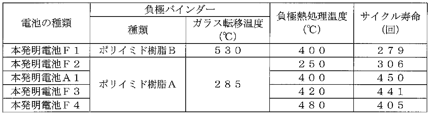
- a precursor of polyimide resin shown in Chemical Formula 3 (hereinafter sometimes referred to as polyimide resin B) is used.
- a varnish of a certain polyamic acid (a varnish shown in Chemical Formula 4 below, the solvent is NMP, and its concentration is 16% by mass in terms of the amount of polyimide resin B after imidization by heat treatment of the negative electrode active material).
- a battery was fabricated in the same manner as in Example 1 of the first example except that the mass ratio of the negative electrode active material particles to the polyimide resin B after imidization was 90:10.
- the battery thus produced is hereinafter referred to as the present invention battery F1.
- thermoelectric heat treatment heat treatment at 400 ° C for 10 hours in an argon atmosphere, heat treatment at 250 ° C for 10 hours in an argon atmosphere, heat treatment for 10 hours at 420 ° C in an argon atmosphere, or A battery was fabricated in the same manner as in Example 1 of the first example except that each heat treatment was performed at 480 ° C. for 10 hours in an argon atmosphere.
- the batteries thus produced are hereinafter referred to as the present invention batteries F2 to F4, respectively.
- the batteries of the present invention F1 to F4 were charged and discharged under the same conditions as those shown in the experiment of the first embodiment, and the cycle life was examined. The results are shown in Table 6. Table 6 also shows the cycle life of the battery A 1 of the present invention.
- the batteries of the present invention Al, F3, and F4 that were heat-treated at a temperature higher than the glass transition temperature of the negative electrode binder were heat-treated at a temperature lower than the glass transition temperature of the negative electrode binder. It can be seen that the present invention shows excellent cycle characteristics as compared with the present invention batteries Fl and F2.
- the electrode heat treatment is carried out at a temperature higher than the glass transition temperature of the negative electrode binder, so that the fuser of the noinda occurs, and the unevenness of the surface of the polycrystalline silicon particles and the unevenness of the surface of the negative electrode current collector In addition, it is considered that the anchor effect by the noinda was expressed by the noinda entering, and the high adhesion was caused.
- the batteries Al and F3 of the present invention in which the electrode heat treatment was performed at 450 ° C or lower showed better cycle characteristics than the battery F4 of the present invention in which the electrode heat treatment was performed at 450 ° C or higher. I can speak. Therefore, when each negative electrode current collector was examined after the test, it was confirmed that in the batteries Al and F3 of the present invention in which the electrode heat treatment was performed at 450 ° C. or less, the negative electrode current collector was not deformed. In the battery F4 of the present invention performed at C or higher, it was confirmed that the negative electrode current collector after the test was deformed! Therefore, in the battery F4 of the present invention, the electrode heat treatment was performed at 450 ° C.
- the physical properties (imido ratio, glass transition temperature) of the binder resin B were measured in the same manner as in Experiment 3 of the first example.
- the imidization ratio of binder resin B was 100%, and the glass transition temperature was 530 ° C.
- the key particles are used as the negative electrode active material particles.
- the key alloy particles or a mixture of the key particles and the key alloy particles may be used.
- carbon material particles can be added to these particles!
- the lithium salt of the electrolyte is not limited to the above LiPF. LiBF, LiA
- the above can also be mixed and used.
- concentration of the lithium salt is not particularly limited, but it is desirable to regulate it to 0.5 to 1.5 mol per liter of the electrolyte.
- Examples of such a cyclic carbonate compound that is preferably contained above are vinylene carbonate, 4,5-dimethylvinylene carbonate, 4,5-jetinorevinylene carbonate, 4,5-di- Propyl vinylene carbonate, 4-ethylenole 5--Methyl vinylene carbonate, 4-ethyl butyl 5-Propyl vinylene carbonate, 4-methyl 5-ethylene methyl-butylene carbonate, butyl ethylene carbonate, dibuty Examples include ren carbonate.
- a carbonate containing CO 2 or F element is contained.
- a solvent include fluoroethylene carbonate and trifluoromethylpropylene carbonate.
- the solvent types of the electrolytic solution used in the present invention include ethylene carbonate, propylene carbonate, and jetyl. Carbonate solvents such as carbonate, ethylmethyl carbonate, dimethyl carbonate and the like are preferable, and a combination of cyclic carbonate and chain carbonate is more preferable.
- the present invention is not limited to a liquid battery, but can be applied to a gel polymer battery.
- the polymer material in this case include polyether solid polymer, polycarbonate solid polymer, polyacrylonitrile solid polymer, oxetane polymer, epoxy polymer, and a copolymer of two or more of these, Cross-linked polymers or PVDF are exemplified, and a solid electrolyte formed by combining this polymer material, a lithium salt and an electrolyte into a gel can be used.
- the present invention can be applied to, for example, a drive power source of a mobile information terminal such as a mobile phone, a notebook computer, and a PDA, and in particular, a use requiring a high capacity.
- a mobile information terminal such as a mobile phone, a notebook computer, and a PDA
- FIG. 1 is a front view of a battery according to the best mode of the present invention.
- FIG. 2 is a cross-sectional view taken along line AA in FIG.
- FIG. 3 is a graph showing the relationship between the average particle diameter of the key particles and the cycle life.
- FIG. 4 is an explanatory diagram for explaining the surface roughness Ra.
- FIG. 5 is an explanatory diagram for explaining an average peak interval S.
- FIG. 6 is a photograph showing a cross-section of the negative electrode in the present battery A1 after 300 cycles.
- FIG. 7 is a photograph showing a cross section of a negative electrode in a comparative battery Zl after 300 cycles.
Landscapes
- Chemical & Material Sciences (AREA)
- Chemical Kinetics & Catalysis (AREA)
- Electrochemistry (AREA)
- General Chemical & Material Sciences (AREA)
- Engineering & Computer Science (AREA)
- Manufacturing & Machinery (AREA)
- Materials Engineering (AREA)
- Battery Electrode And Active Subsutance (AREA)
- Secondary Cells (AREA)
- Cell Electrode Carriers And Collectors (AREA)
Abstract
Description


Claims
Priority Applications (2)
| Application Number | Priority Date | Filing Date | Title |
|---|---|---|---|
| JP2008508563A JP5178508B2 (ja) | 2006-03-30 | 2007-03-28 | リチウム二次電池 |
| US12/295,182 US9263771B2 (en) | 2006-03-30 | 2007-03-28 | Lithium secondary battery and method of manufacturing the same |
Applications Claiming Priority (2)
| Application Number | Priority Date | Filing Date | Title |
|---|---|---|---|
| JP2006-094846 | 2006-03-30 | ||
| JP2006094846 | 2006-03-30 |
Publications (1)
| Publication Number | Publication Date |
|---|---|
| WO2007114168A1 true WO2007114168A1 (ja) | 2007-10-11 |
Family
ID=38563437
Family Applications (1)
| Application Number | Title | Priority Date | Filing Date |
|---|---|---|---|
| PCT/JP2007/056655 Ceased WO2007114168A1 (ja) | 2006-03-30 | 2007-03-28 | リチウム二次電池及びその製造方法 |
Country Status (5)
| Country | Link |
|---|---|
| US (1) | US9263771B2 (ja) |
| JP (1) | JP5178508B2 (ja) |
| KR (1) | KR100984684B1 (ja) |
| CN (1) | CN101411007A (ja) |
| WO (1) | WO2007114168A1 (ja) |
Cited By (41)
| Publication number | Priority date | Publication date | Assignee | Title |
|---|---|---|---|---|
| JP2009123424A (ja) * | 2007-11-13 | 2009-06-04 | Sony Corp | 非水電解質二次電池 |
| JP2009224168A (ja) * | 2008-03-17 | 2009-10-01 | Shin Etsu Chem Co Ltd | 非水電解質二次電池負極材及びそれを用いた非水電解質二次電池 |
| US7683359B2 (en) | 2002-11-05 | 2010-03-23 | Nexeon Ltd. | Structured silicon anode |
| EP2104175A3 (en) * | 2008-03-17 | 2010-12-01 | Shin-Etsu Chemical Co., Ltd. | Non-aqueous electrolyte secondary battery, negative electrode material, and making method |
| JP2011258407A (ja) * | 2010-06-09 | 2011-12-22 | Furukawa Battery Co Ltd:The | リチウムイオン二次電池用負極およびリチウムイオン二次電池 |
| US8101298B2 (en) | 2006-01-23 | 2012-01-24 | Nexeon Ltd. | Method of fabricating fibres composed of silicon or a silicon-based material and their use in lithium rechargeable batteries |
| JP2012527069A (ja) * | 2009-05-11 | 2012-11-01 | ネグゼオン・リミテッド | リチウムイオン再充電可能電池セル |
| WO2013058091A1 (ja) * | 2011-10-17 | 2013-04-25 | 日産自動車株式会社 | 電気デバイス用負極活物質 |
| JP2013179059A (ja) * | 2009-05-11 | 2013-09-09 | Nexeon Ltd | リチウムイオン再充電可能電池セル |
| JP2013229347A (ja) * | 2007-11-12 | 2013-11-07 | Shin Etsu Chem Co Ltd | 非水電解質二次電池負極材の活物質用多結晶珪素粒子の製造方法 |
| US8585918B2 (en) | 2006-01-23 | 2013-11-19 | Nexeon Ltd. | Method of etching a silicon-based material |
| JP2014022319A (ja) * | 2012-07-23 | 2014-02-03 | Toyota Industries Corp | 二次電池用負極活物質、その製造方法、二次電池用負極、二次電池、及びSi−酸化物固体電解質複合体 |
| US8642211B2 (en) | 2007-07-17 | 2014-02-04 | Nexeon Limited | Electrode including silicon-comprising fibres and electrochemical cells including the same |
| JP2014114330A (ja) * | 2012-12-06 | 2014-06-26 | Unitika Ltd | シリコン系粒子分散塗液およびその製造方法 |
| US8772174B2 (en) | 2010-04-09 | 2014-07-08 | Nexeon Ltd. | Method of fabricating structured particles composed of silicon or silicon-based material and their use in lithium rechargeable batteries |
| US8870975B2 (en) | 2007-07-17 | 2014-10-28 | Nexeon Ltd. | Method of fabricating structured particles composed of silicon or a silicon-based material and their use in lithium rechargeable batteries |
| US8945774B2 (en) | 2010-06-07 | 2015-02-03 | Nexeon Ltd. | Additive for lithium ion rechageable battery cells |
| US8962183B2 (en) | 2009-05-07 | 2015-02-24 | Nexeon Limited | Method of making silicon anode material for rechargeable cells |
| JP2015508934A (ja) * | 2012-01-30 | 2015-03-23 | ネクソン リミテッドNexeon Limited | Si/C電気活性材料組成物 |
| US9012079B2 (en) | 2007-07-17 | 2015-04-21 | Nexeon Ltd | Electrode comprising structured silicon-based material |
| WO2015152094A1 (ja) * | 2014-03-31 | 2015-10-08 | 株式会社クレハ | 非水電解質二次電池 |
| WO2015152095A1 (ja) * | 2014-03-31 | 2015-10-08 | 株式会社クレハ | 非水電解質二次電池 |
| JP2015195171A (ja) * | 2014-03-25 | 2015-11-05 | 東ソー株式会社 | リチウムイオン2次電池用負極活物質およびその製造方法 |
| US9184438B2 (en) | 2008-10-10 | 2015-11-10 | Nexeon Ltd. | Method of fabricating structured particles composed of silicon or a silicon-based material and their use in lithium rechargeable batteries |
| JP2016015299A (ja) * | 2014-06-30 | 2016-01-28 | ティーエムシー株式会社 | シリコン微細粒子 |
| US9252426B2 (en) | 2007-05-11 | 2016-02-02 | Nexeon Limited | Silicon anode for a rechargeable battery |
| JP2016103337A (ja) * | 2014-11-27 | 2016-06-02 | 株式会社日立製作所 | リチウムイオン二次電池及びリチウムイオン二次電池の製造方法 |
| JP2016139521A (ja) * | 2015-01-27 | 2016-08-04 | 日産自動車株式会社 | 非水電解質二次電池 |
| JP2016164884A (ja) * | 2011-11-11 | 2016-09-08 | 株式会社豊田自動織機 | リチウムイオン二次電池用の負極材及び負極、並びにリチウムイオン二次電池 |
| US9647263B2 (en) | 2010-09-03 | 2017-05-09 | Nexeon Limited | Electroactive material |
| US9853292B2 (en) | 2009-05-11 | 2017-12-26 | Nexeon Limited | Electrode composition for a secondary battery cell |
| US9871248B2 (en) | 2010-09-03 | 2018-01-16 | Nexeon Limited | Porous electroactive material |
| JP2018041675A (ja) * | 2016-09-09 | 2018-03-15 | 株式会社豊田自動織機 | リチウムイオン二次電池 |
| KR20180035915A (ko) * | 2015-08-12 | 2018-04-06 | 와커 헤미 아게 | 리튬 이온 배터리용 실리콘 입자-함유 애노드 재료 |
| JP2019117796A (ja) * | 2017-08-23 | 2019-07-18 | 宇部興産株式会社 | 電極用バインダー樹脂、電極合剤ペースト、電極、及び電極の製造方法 |
| US10490817B2 (en) | 2009-05-19 | 2019-11-26 | Oned Material Llc | Nanostructured materials for battery applications |
| WO2021261506A1 (ja) * | 2020-06-27 | 2021-12-30 | 松永正文 | 粒子の製造方法、粒子またはスラリーの塗布方法、2次電池または2次電池の製造方法、全固体電池または全固体電池の製造方法、ledまたはledの製造方法、蛍光体シートまたは蛍光体シートの製造方法 |
| CN117908493A (zh) * | 2024-01-26 | 2024-04-19 | 深圳市磐锋精密技术有限公司 | 一种基于大数据的锂电池生产监测系统及其方法 |
| JP2025506415A (ja) * | 2022-07-13 | 2025-03-11 | エルジー エナジー ソリューション リミテッド | 負極活物質、負極活物質の製造方法、負極組成物、これを含むリチウム二次電池用負極、および負極を含むリチウム二次電池 |
| JP2026500935A (ja) * | 2023-08-01 | 2026-01-09 | エルジー エナジー ソリューション リミテッド | 負極組成物、これを含むリチウム二次電池用負極、および負極を含むリチウム二次電池 |
| JP2026506266A (ja) * | 2023-07-14 | 2026-02-24 | エルジー エナジー ソリューション リミテッド | 負極活物質、負極活物質の製造方法、負極組成物、これを含むリチウム二次電池用負極、および負極を含むリチウム二次電池 |
Families Citing this family (33)
| Publication number | Priority date | Publication date | Assignee | Title |
|---|---|---|---|---|
| GB2464157B (en) | 2008-10-10 | 2010-09-01 | Nexeon Ltd | A method of fabricating structured particles composed of silicon or a silicon-based material |
| JP5662698B2 (ja) * | 2009-05-15 | 2015-02-04 | 新日鉄住金化学株式会社 | リチウム二次電池用負極活物質及びそれを用いた車載用リチウム二次電池 |
| JP5454353B2 (ja) * | 2010-05-21 | 2014-03-26 | 信越化学工業株式会社 | 非水電解質二次電池負極材用珪素酸化物及びその製造方法、ならびに負極、リチウムイオン二次電池及び電気化学キャパシタ |
| WO2013002163A1 (ja) * | 2011-06-27 | 2013-01-03 | 三井金属鉱業株式会社 | 非水電解液二次電池用負極活物質 |
| US20130052525A1 (en) * | 2011-08-24 | 2013-02-28 | Sumitomo Chemical Company, Limited | Sodium secondary battery |
| JP6016038B2 (ja) * | 2012-04-10 | 2016-10-26 | トヨタ自動車株式会社 | 非水電解質二次電池 |
| KR101430709B1 (ko) * | 2012-07-19 | 2014-08-14 | 엠케이전자 주식회사 | 이차 전지용 음극 활물질 및 이를 포함하는 이차 전지 |
| JP6459023B2 (ja) * | 2013-06-18 | 2019-01-30 | 株式会社Gsユアサ | 蓄電素子及び蓄電モジュール |
| KR101496309B1 (ko) | 2013-08-09 | 2015-02-26 | 오씨아이 주식회사 | 음극활물질용 실리콘 슬러리 및 탄소-실리콘 복합체 |
| CN103531812B (zh) * | 2013-09-26 | 2018-02-27 | 东莞新能源科技有限公司 | 锂离子二次电池及其负极片 |
| US20150221936A1 (en) * | 2014-02-05 | 2015-08-06 | GM Global Technology Operations LLC | Negative electrode material for a lithium ion battery |
| EP2966710A1 (en) * | 2014-07-08 | 2016-01-13 | Umicore SA | A plurality of silicon domains and the use thereof, a composite particle made thereof, and an electrode for a battery |
| US10490818B2 (en) * | 2015-01-29 | 2019-11-26 | Envision Aesc Energy Devices Ltd. | Negative electrode for lithium ion secondary battery, and lithium ion secondary battery |
| US10014552B1 (en) * | 2015-07-01 | 2018-07-03 | Physical Optics Corporation | Lithium ion rechargeable battery |
| WO2018024317A1 (de) | 2016-08-02 | 2018-02-08 | Wacker Chemie Ag | Lithium-ionen-batterien |
| CN109792041A (zh) | 2016-10-05 | 2019-05-21 | 瓦克化学股份公司 | 锂离子电池 |
| NO345463B1 (en) | 2017-04-06 | 2021-02-15 | Elkem Materials | Silicon powder for use in anodes for lithium-ion batteries and method for production of silicon powder |
| KR102447619B1 (ko) | 2017-09-18 | 2022-09-27 | 주식회사 엘지에너지솔루션 | 지그를 이용한 고정 과정을 포함하는 파우치형 전지셀 제조방법 |
| KR102326851B1 (ko) * | 2017-11-13 | 2021-11-17 | 한국전자기술연구원 | 리튬이차전지용 음극 및 그 제조방법 |
| CN111615768B (zh) * | 2018-01-15 | 2023-04-18 | 尤米科尔公司 | 用于蓄电池负电极中的复合粉末以及包括此类复合粉末的蓄电池 |
| US10833311B2 (en) | 2018-07-03 | 2020-11-10 | International Business Machines Corporation | Method of making an anode structure containing a porous region |
| US10833357B2 (en) | 2018-07-03 | 2020-11-10 | International Business Machines Corporation | Battery structure with an anode structure containing a porous region and method of operation |
| US10833356B2 (en) | 2018-07-03 | 2020-11-10 | International Business Machines Corporation | Kinetically fast charging lithium-ion battery |
| US10777842B2 (en) | 2018-07-03 | 2020-09-15 | International Business Machines Corporation | Rechargeable lithium-ion battery with an anode structure containing a porous region |
| CN110010902A (zh) | 2019-03-29 | 2019-07-12 | 宁德新能源科技有限公司 | 电极极片和包含所述电极极片的电化学装置 |
| CN109841794B (zh) * | 2019-03-29 | 2021-07-20 | 东莞新能安科技有限公司 | 电极极片和包含所述电极极片的电化学装置 |
| CN109980177B (zh) | 2019-03-29 | 2021-10-22 | 东莞新能安科技有限公司 | 电极极片和包含所述电极极片的电化学装置 |
| CN112103556A (zh) * | 2020-11-09 | 2020-12-18 | 中国电力科学研究院有限公司 | 一种二次电池及其修复方法 |
| US20240170680A1 (en) * | 2021-03-31 | 2024-05-23 | Nippon Steel Chemical & Material Co., Ltd. | Steel foil for current collector, electrode, and battery |
| KR20220169155A (ko) * | 2021-06-18 | 2022-12-27 | 에스케이온 주식회사 | 음극 활물질, 이를 포함하는 음극용 조성물 및 이로부터 제조된 이차 전지 |
| CN117410447A (zh) * | 2021-09-08 | 2024-01-16 | 珠海冠宇电池股份有限公司 | 一种锂离子电池和电子装置 |
| US12706332B2 (en) * | 2022-06-01 | 2026-08-11 | Enevate Corporation | Recycling silicon from batteries with silicon-based active materials |
| DE102022206474B4 (de) | 2022-06-28 | 2024-03-21 | Volkswagen Aktiengesellschaft | Verfahren zur Herstellung einer Silizium-Kohlenstoff-Anode und nach dem Verfahren erhältliche Silizium-Kohlenstoff-Anode |
Citations (8)
| Publication number | Priority date | Publication date | Assignee | Title |
|---|---|---|---|---|
| JP2001325958A (ja) * | 2000-03-07 | 2001-11-22 | Matsushita Electric Ind Co Ltd | 非水電解質二次電池 |
| JP2004022433A (ja) * | 2002-06-19 | 2004-01-22 | Sanyo Electric Co Ltd | リチウム二次電池用負極及びリチウム二次電池 |
| JP2004303593A (ja) * | 2003-03-31 | 2004-10-28 | Mitsubishi Materials Corp | リチウム二次電池用負極材料及びその製造方法 |
| JP2004335271A (ja) * | 2003-05-08 | 2004-11-25 | Matsushita Electric Ind Co Ltd | 非水電解質二次電池用負極活物質の製造方法 |
| JP2005011802A (ja) * | 2003-05-22 | 2005-01-13 | Matsushita Electric Ind Co Ltd | 非水電解質二次電池とその製造方法 |
| JP2005190977A (ja) * | 2003-06-19 | 2005-07-14 | Sanyo Electric Co Ltd | リチウム二次電池及びその製造方法 |
| JP2005228565A (ja) * | 2004-02-12 | 2005-08-25 | Sony Corp | 電解液および電池 |
| CN1753235A (zh) * | 2004-09-24 | 2006-03-29 | 三洋电机株式会社 | 锂二次电池 |
Family Cites Families (19)
| Publication number | Priority date | Publication date | Assignee | Title |
|---|---|---|---|---|
| GB1468591A (en) * | 1973-06-01 | 1977-03-30 | Deutsche Automobilgesellsch | Electrodes for galvanic cells |
| JP3008269B2 (ja) | 1997-03-11 | 2000-02-14 | 脇原 将孝 | 二次電池 |
| KR100274884B1 (ko) | 1998-01-22 | 2000-12-15 | 김순택 | 양.음극의 용량비를 보상한 2차 전지 |
| US6235427B1 (en) * | 1998-05-13 | 2001-05-22 | Fuji Photo Film Co., Ltd. | Nonaqueous secondary battery containing silicic material |
| US6555272B2 (en) * | 1998-09-11 | 2003-04-29 | Nippon Steel Corporation | Lithium secondary battery and active material for negative electrode in lithium secondary battery |
| WO2000033404A1 (en) * | 1998-12-03 | 2000-06-08 | Kao Corporation | Lithium secondary cell and method for manufacturing the same |
| EP1313158A3 (en) * | 2001-11-20 | 2004-09-08 | Canon Kabushiki Kaisha | Electrode material for rechargeable lithium battery, electrode comprising said electrode material, rechargeable lithium battery having said electrode , and process for the production thereof |
| JP4225727B2 (ja) * | 2001-12-28 | 2009-02-18 | 三洋電機株式会社 | リチウム二次電池用負極及びリチウム二次電池 |
| AU2003221334A1 (en) * | 2002-03-08 | 2003-09-22 | Mitsubishi Chemical Corporation | Nonaqueous electrolyte and lithium-ion secondary battery containing the same |
| TWI278429B (en) * | 2002-05-17 | 2007-04-11 | Shinetsu Chemical Co | Conductive silicon composite, preparation thereof, and negative electrode material for non-aqueous electrolyte secondary cell |
| JP4025995B2 (ja) * | 2002-11-26 | 2007-12-26 | 信越化学工業株式会社 | 非水電解質二次電池負極材及びその製造方法並びにリチウムイオン二次電池 |
| JP4464173B2 (ja) | 2003-03-26 | 2010-05-19 | キヤノン株式会社 | リチウム二次電池用の電極材料、該電極材料を有する電極構造体、及び該電極構造体を有する二次電池 |
| JP2004319390A (ja) | 2003-04-18 | 2004-11-11 | Matsushita Electric Ind Co Ltd | 非水電解質二次電池 |
| KR100765053B1 (ko) | 2003-06-09 | 2007-10-09 | 산요덴키가부시키가이샤 | 리튬 이차 전지 및 그의 제조 방법 |
| DE10353995A1 (de) * | 2003-11-19 | 2005-06-09 | Degussa Ag | Nanoskaliges, kristallines Siliciumpulver |
| DE102004016766A1 (de) | 2004-04-01 | 2005-10-20 | Degussa | Nanoskalige Siliziumpartikel in negativen Elektrodenmaterialien für Lithium-Ionen-Batterien |
| JP4117573B2 (ja) * | 2004-07-21 | 2008-07-16 | ソニー株式会社 | 電池 |
| JP4868786B2 (ja) * | 2004-09-24 | 2012-02-01 | 三洋電機株式会社 | リチウム二次電池 |
| KR100763892B1 (ko) * | 2006-01-20 | 2007-10-05 | 삼성에스디아이 주식회사 | 음극 활물질, 그 제조 방법, 및 이를 채용한 음극과 리튬전지 |
-
2007
- 2007-03-28 US US12/295,182 patent/US9263771B2/en active Active
- 2007-03-28 CN CNA2007800107562A patent/CN101411007A/zh active Pending
- 2007-03-28 WO PCT/JP2007/056655 patent/WO2007114168A1/ja not_active Ceased
- 2007-03-28 KR KR1020087021285A patent/KR100984684B1/ko not_active Expired - Fee Related
- 2007-03-28 JP JP2008508563A patent/JP5178508B2/ja active Active
Patent Citations (8)
| Publication number | Priority date | Publication date | Assignee | Title |
|---|---|---|---|---|
| JP2001325958A (ja) * | 2000-03-07 | 2001-11-22 | Matsushita Electric Ind Co Ltd | 非水電解質二次電池 |
| JP2004022433A (ja) * | 2002-06-19 | 2004-01-22 | Sanyo Electric Co Ltd | リチウム二次電池用負極及びリチウム二次電池 |
| JP2004303593A (ja) * | 2003-03-31 | 2004-10-28 | Mitsubishi Materials Corp | リチウム二次電池用負極材料及びその製造方法 |
| JP2004335271A (ja) * | 2003-05-08 | 2004-11-25 | Matsushita Electric Ind Co Ltd | 非水電解質二次電池用負極活物質の製造方法 |
| JP2005011802A (ja) * | 2003-05-22 | 2005-01-13 | Matsushita Electric Ind Co Ltd | 非水電解質二次電池とその製造方法 |
| JP2005190977A (ja) * | 2003-06-19 | 2005-07-14 | Sanyo Electric Co Ltd | リチウム二次電池及びその製造方法 |
| JP2005228565A (ja) * | 2004-02-12 | 2005-08-25 | Sony Corp | 電解液および電池 |
| CN1753235A (zh) * | 2004-09-24 | 2006-03-29 | 三洋电机株式会社 | 锂二次电池 |
Cited By (75)
| Publication number | Priority date | Publication date | Assignee | Title |
|---|---|---|---|---|
| US8017430B2 (en) | 2002-11-05 | 2011-09-13 | Nexeon Ltd. | Structured silicon anode |
| US8384058B2 (en) | 2002-11-05 | 2013-02-26 | Nexeon Ltd. | Structured silicon anode |
| US7683359B2 (en) | 2002-11-05 | 2010-03-23 | Nexeon Ltd. | Structured silicon anode |
| US7842535B2 (en) | 2002-11-05 | 2010-11-30 | Nexeon Ltd. | Structured silicon anode |
| US9583762B2 (en) | 2006-01-23 | 2017-02-28 | Nexeon Limited | Method of fabricating fibres composed of silicon or a silicon-based material and their use in lithium rechargeable batteries |
| US8585918B2 (en) | 2006-01-23 | 2013-11-19 | Nexeon Ltd. | Method of etching a silicon-based material |
| US8101298B2 (en) | 2006-01-23 | 2012-01-24 | Nexeon Ltd. | Method of fabricating fibres composed of silicon or a silicon-based material and their use in lithium rechargeable batteries |
| US8597831B2 (en) | 2006-01-23 | 2013-12-03 | Nexeon Ltd. | Method of fabricating fibres composed of silicon or a silicon-based material and their use in lithium rechargeable batteries |
| US9871249B2 (en) | 2007-05-11 | 2018-01-16 | Nexeon Limited | Silicon anode for a rechargeable battery |
| US9252426B2 (en) | 2007-05-11 | 2016-02-02 | Nexeon Limited | Silicon anode for a rechargeable battery |
| US8940437B2 (en) | 2007-07-17 | 2015-01-27 | Nexeon Limited | Method of fabricating structured particles composed of silicon or a silicon-based material and their use in lithium rechargeable batteries |
| US8870975B2 (en) | 2007-07-17 | 2014-10-28 | Nexeon Ltd. | Method of fabricating structured particles composed of silicon or a silicon-based material and their use in lithium rechargeable batteries |
| US9871244B2 (en) | 2007-07-17 | 2018-01-16 | Nexeon Limited | Method of fabricating structured particles composed of silicon or a silicon-based material and their use in lithium rechargeable batteries |
| US8642211B2 (en) | 2007-07-17 | 2014-02-04 | Nexeon Limited | Electrode including silicon-comprising fibres and electrochemical cells including the same |
| US9012079B2 (en) | 2007-07-17 | 2015-04-21 | Nexeon Ltd | Electrode comprising structured silicon-based material |
| JP2013229347A (ja) * | 2007-11-12 | 2013-11-07 | Shin Etsu Chem Co Ltd | 非水電解質二次電池負極材の活物質用多結晶珪素粒子の製造方法 |
| KR101522963B1 (ko) * | 2007-11-12 | 2015-05-26 | 산요덴키가부시키가이샤 | 비수 전해질 2차전지 부극재, 비수 전해질 2차전지용 부극 및 비수 전해질 2차전지, 및 비수 전해질 2차전지 부극재의 활물질용 다결정 규소 입자의 제조방법 |
| US9647298B2 (en) | 2007-11-13 | 2017-05-09 | Sony Corporation | Nonaqueous electrolyte battery and electrical apparatus |
| US8609286B2 (en) | 2007-11-13 | 2013-12-17 | Sony Corporation | Nonaqueous electrolyte secondary battery |
| JP2009123424A (ja) * | 2007-11-13 | 2009-06-04 | Sony Corp | 非水電解質二次電池 |
| US10707539B2 (en) | 2007-11-13 | 2020-07-07 | Murata Manufacturing Co., Ltd. | Battery |
| US9831532B2 (en) | 2007-11-13 | 2017-11-28 | Sony Corporation | Nonaqueous electrolyte secondary battery |
| US8105718B2 (en) | 2008-03-17 | 2012-01-31 | Shin-Etsu Chemical Co., Ltd. | Non-aqueous electrolyte secondary battery, negative electrode material, and making method |
| EP2104175A3 (en) * | 2008-03-17 | 2010-12-01 | Shin-Etsu Chemical Co., Ltd. | Non-aqueous electrolyte secondary battery, negative electrode material, and making method |
| JP2009224168A (ja) * | 2008-03-17 | 2009-10-01 | Shin Etsu Chem Co Ltd | 非水電解質二次電池負極材及びそれを用いた非水電解質二次電池 |
| US9184438B2 (en) | 2008-10-10 | 2015-11-10 | Nexeon Ltd. | Method of fabricating structured particles composed of silicon or a silicon-based material and their use in lithium rechargeable batteries |
| US9553304B2 (en) | 2009-05-07 | 2017-01-24 | Nexeon Limited | Method of making silicon anode material for rechargeable cells |
| US8962183B2 (en) | 2009-05-07 | 2015-02-24 | Nexeon Limited | Method of making silicon anode material for rechargeable cells |
| JP2012527069A (ja) * | 2009-05-11 | 2012-11-01 | ネグゼオン・リミテッド | リチウムイオン再充電可能電池セル |
| US10050275B2 (en) | 2009-05-11 | 2018-08-14 | Nexeon Limited | Binder for lithium ion rechargeable battery cells |
| US9853292B2 (en) | 2009-05-11 | 2017-12-26 | Nexeon Limited | Electrode composition for a secondary battery cell |
| JP2013179059A (ja) * | 2009-05-11 | 2013-09-09 | Nexeon Ltd | リチウムイオン再充電可能電池セル |
| US9608272B2 (en) | 2009-05-11 | 2017-03-28 | Nexeon Limited | Composition for a secondary battery cell |
| US10490817B2 (en) | 2009-05-19 | 2019-11-26 | Oned Material Llc | Nanostructured materials for battery applications |
| US11233240B2 (en) | 2009-05-19 | 2022-01-25 | Oned Material, Inc. | Nanostructured materials for battery applications |
| US11600821B2 (en) | 2009-05-19 | 2023-03-07 | Oned Material, Inc. | Nanostructured materials for battery applications |
| US12224441B2 (en) | 2009-05-19 | 2025-02-11 | Oned Material, Inc. | Nanostructured materials for battery |
| US12469849B2 (en) | 2009-05-19 | 2025-11-11 | Oned Material, Inc. | Nanostructured materials for battery applications |
| US8772174B2 (en) | 2010-04-09 | 2014-07-08 | Nexeon Ltd. | Method of fabricating structured particles composed of silicon or silicon-based material and their use in lithium rechargeable batteries |
| US9368836B2 (en) | 2010-06-07 | 2016-06-14 | Nexeon Ltd. | Additive for lithium ion rechargeable battery cells |
| US8945774B2 (en) | 2010-06-07 | 2015-02-03 | Nexeon Ltd. | Additive for lithium ion rechageable battery cells |
| JP2011258407A (ja) * | 2010-06-09 | 2011-12-22 | Furukawa Battery Co Ltd:The | リチウムイオン二次電池用負極およびリチウムイオン二次電池 |
| US9647263B2 (en) | 2010-09-03 | 2017-05-09 | Nexeon Limited | Electroactive material |
| US9947920B2 (en) | 2010-09-03 | 2018-04-17 | Nexeon Limited | Electroactive material |
| US9871248B2 (en) | 2010-09-03 | 2018-01-16 | Nexeon Limited | Porous electroactive material |
| JP2013089408A (ja) * | 2011-10-17 | 2013-05-13 | Nissan Motor Co Ltd | 電気デバイス用負極活物質 |
| CN103875100A (zh) * | 2011-10-17 | 2014-06-18 | 日产自动车株式会社 | 电气器件用负极活性物质 |
| WO2013058091A1 (ja) * | 2011-10-17 | 2013-04-25 | 日産自動車株式会社 | 電気デバイス用負極活物質 |
| US9979016B2 (en) | 2011-10-17 | 2018-05-22 | Nissan Motor Co., Ltd. | Negative electrode active material for electric device |
| JP2016164884A (ja) * | 2011-11-11 | 2016-09-08 | 株式会社豊田自動織機 | リチウムイオン二次電池用の負極材及び負極、並びにリチウムイオン二次電池 |
| JP2015508934A (ja) * | 2012-01-30 | 2015-03-23 | ネクソン リミテッドNexeon Limited | Si/C電気活性材料組成物 |
| JP2014022319A (ja) * | 2012-07-23 | 2014-02-03 | Toyota Industries Corp | 二次電池用負極活物質、その製造方法、二次電池用負極、二次電池、及びSi−酸化物固体電解質複合体 |
| JP2014114330A (ja) * | 2012-12-06 | 2014-06-26 | Unitika Ltd | シリコン系粒子分散塗液およびその製造方法 |
| JP2015195171A (ja) * | 2014-03-25 | 2015-11-05 | 東ソー株式会社 | リチウムイオン2次電池用負極活物質およびその製造方法 |
| WO2015152095A1 (ja) * | 2014-03-31 | 2015-10-08 | 株式会社クレハ | 非水電解質二次電池 |
| WO2015152094A1 (ja) * | 2014-03-31 | 2015-10-08 | 株式会社クレハ | 非水電解質二次電池 |
| JPWO2015152095A1 (ja) * | 2014-03-31 | 2017-04-13 | 株式会社クレハ | 非水電解質二次電池 |
| JPWO2015152094A1 (ja) * | 2014-03-31 | 2017-04-13 | 株式会社クレハ | 非水電解質二次電池 |
| JP2016015299A (ja) * | 2014-06-30 | 2016-01-28 | ティーエムシー株式会社 | シリコン微細粒子 |
| JP2016103337A (ja) * | 2014-11-27 | 2016-06-02 | 株式会社日立製作所 | リチウムイオン二次電池及びリチウムイオン二次電池の製造方法 |
| JP2016139521A (ja) * | 2015-01-27 | 2016-08-04 | 日産自動車株式会社 | 非水電解質二次電池 |
| KR20180035915A (ko) * | 2015-08-12 | 2018-04-06 | 와커 헤미 아게 | 리튬 이온 배터리용 실리콘 입자-함유 애노드 재료 |
| JP2018530859A (ja) * | 2015-08-12 | 2018-10-18 | ワッカー ケミー アクチエンゲゼルシャフトWacker Chemie AG | リチウムイオン電池用のシリコン粒子含有アノード材料 |
| KR102200190B1 (ko) | 2015-08-12 | 2021-01-11 | 와커 헤미 아게 | 리튬 이온 배터리용 실리콘 입자-함유 애노드 재료 |
| CN107925072B (zh) * | 2015-08-12 | 2021-05-07 | 瓦克化学股份公司 | 用于锂离子电池的含硅颗粒的阳极材料 |
| CN107925072A (zh) * | 2015-08-12 | 2018-04-17 | 瓦克化学股份公司 | 用于锂离子电池的含硅颗粒的阳极材料 |
| JP2018041675A (ja) * | 2016-09-09 | 2018-03-15 | 株式会社豊田自動織機 | リチウムイオン二次電池 |
| JP2019117796A (ja) * | 2017-08-23 | 2019-07-18 | 宇部興産株式会社 | 電極用バインダー樹脂、電極合剤ペースト、電極、及び電極の製造方法 |
| JP7489224B2 (ja) | 2017-08-23 | 2024-05-23 | Ube株式会社 | 電極用バインダー、及び電極 |
| JP2020115474A (ja) * | 2017-08-23 | 2020-07-30 | 宇部興産株式会社 | 電極用バインダー樹脂、電極合剤ペースト、電極、及び電極の製造方法 |
| WO2021261506A1 (ja) * | 2020-06-27 | 2021-12-30 | 松永正文 | 粒子の製造方法、粒子またはスラリーの塗布方法、2次電池または2次電池の製造方法、全固体電池または全固体電池の製造方法、ledまたはledの製造方法、蛍光体シートまたは蛍光体シートの製造方法 |
| JP2025506415A (ja) * | 2022-07-13 | 2025-03-11 | エルジー エナジー ソリューション リミテッド | 負極活物質、負極活物質の製造方法、負極組成物、これを含むリチウム二次電池用負極、および負極を含むリチウム二次電池 |
| JP2026506266A (ja) * | 2023-07-14 | 2026-02-24 | エルジー エナジー ソリューション リミテッド | 負極活物質、負極活物質の製造方法、負極組成物、これを含むリチウム二次電池用負極、および負極を含むリチウム二次電池 |
| JP2026500935A (ja) * | 2023-08-01 | 2026-01-09 | エルジー エナジー ソリューション リミテッド | 負極組成物、これを含むリチウム二次電池用負極、および負極を含むリチウム二次電池 |
| CN117908493A (zh) * | 2024-01-26 | 2024-04-19 | 深圳市磐锋精密技术有限公司 | 一种基于大数据的锂电池生产监测系统及其方法 |
Also Published As
| Publication number | Publication date |
|---|---|
| KR20080091501A (ko) | 2008-10-13 |
| JP5178508B2 (ja) | 2013-04-10 |
| CN101411007A (zh) | 2009-04-15 |
| JPWO2007114168A1 (ja) | 2009-08-13 |
| US9263771B2 (en) | 2016-02-16 |
| US20090305129A1 (en) | 2009-12-10 |
| KR100984684B1 (ko) | 2010-10-01 |
Similar Documents
| Publication | Publication Date | Title |
|---|---|---|
| JP5178508B2 (ja) | リチウム二次電池 | |
| JP5398962B2 (ja) | リチウム二次電池及びその製造方法 | |
| JP5361233B2 (ja) | リチウム二次電池及びその製造方法 | |
| JP4979432B2 (ja) | 円筒型リチウム二次電池 | |
| JP5361232B2 (ja) | リチウム二次電池及びその製造方法 | |
| KR101265340B1 (ko) | 리튬 이온 배터리용 음극 물질의 나노스케일 규소 입자 | |
| JP6010279B2 (ja) | 非水電解質二次電池用負極活物質の製造方法 | |
| EP4089764B1 (en) | Positive electrode material for lithium secondary battery, and positive electrode and lithium secondary battery which include the same | |
| US20090087731A1 (en) | Lithium secondary battery | |
| US20080070120A1 (en) | Non-aqueous electrolyte secondary battery and making method | |
| JP2009099523A (ja) | リチウム二次電池 | |
| CN101137765A (zh) | 涂覆的碳颗粒的制造方法及其在锂离子电池阳极材料中的应用 | |
| CN113795944A (zh) | 负极活性材料、其制备方法以及包含其的负极和二次电池 | |
| EP4020621A1 (en) | Secondary battery and manufacturing method therefor | |
| US20110206981A1 (en) | Lithium secondary battery | |
| JP2024505867A (ja) | 負極活物質、これを含む負極、これを含む二次電池、および負極活物質の製造方法 | |
| CN101675546A (zh) | 电解质、电极组合物以及由此制成的电化学电池 | |
| JP2008123814A (ja) | リチウム二次電池及びその製造方法 | |
| EP4333102A1 (en) | Anode for lithium secondary battery, manufacturing method for anode for lithium secondary battery, and lithium secondary battery including anode | |
| EP4224571A1 (en) | Secondary battery | |
| CN103779552B (zh) | 正极活性物质 | |
| EP4266413A1 (en) | Composite negative electrode active material, method for preparing same, negative electrode comprising same, and secondary battery | |
| EP4345944A2 (en) | Anode active material for a lithium secondary battery, method of preparing the same and lithium secondary battery including the same | |
| EP4625535A1 (en) | Negative electrode composition, negative electrode, and lithium secondary battery | |
| EP4560729A1 (en) | Negative electrode active material, negative electrode, secondary battery, and method for producing negative electrode active material |
Legal Events
| Date | Code | Title | Description |
|---|---|---|---|
| 121 | Ep: the epo has been informed by wipo that ep was designated in this application |
Ref document number: 07740093 Country of ref document: EP Kind code of ref document: A1 |
|
| ENP | Entry into the national phase |
Ref document number: 2008508563 Country of ref document: JP Kind code of ref document: A |
|
| WWE | Wipo information: entry into national phase |
Ref document number: 1020087021285 Country of ref document: KR |
|
| WWE | Wipo information: entry into national phase |
Ref document number: 200780010756.2 Country of ref document: CN |
|
| WWE | Wipo information: entry into national phase |
Ref document number: 12295182 Country of ref document: US |
|
| NENP | Non-entry into the national phase |
Ref country code: DE |
|
| 122 | Ep: pct application non-entry in european phase |
Ref document number: 07740093 Country of ref document: EP Kind code of ref document: A1 |