WO2007069664A1 - 黒鉛粒子、炭素-黒鉛複合粒子及びそれらの製造方法 - Google Patents
黒鉛粒子、炭素-黒鉛複合粒子及びそれらの製造方法 Download PDFInfo
- Publication number
- WO2007069664A1 WO2007069664A1 PCT/JP2006/324877 JP2006324877W WO2007069664A1 WO 2007069664 A1 WO2007069664 A1 WO 2007069664A1 JP 2006324877 W JP2006324877 W JP 2006324877W WO 2007069664 A1 WO2007069664 A1 WO 2007069664A1
- Authority
- WO
- WIPO (PCT)
- Prior art keywords
- graphite
- particles
- carbon
- particle
- graphite particles
- Prior art date
Links
Classifications
-
- C—CHEMISTRY; METALLURGY
- C01—INORGANIC CHEMISTRY
- C01B—NON-METALLIC ELEMENTS; COMPOUNDS THEREOF; METALLOIDS OR COMPOUNDS THEREOF NOT COVERED BY SUBCLASS C01C
- C01B32/00—Carbon; Compounds thereof
- C01B32/20—Graphite
-
- C—CHEMISTRY; METALLURGY
- C01—INORGANIC CHEMISTRY
- C01B—NON-METALLIC ELEMENTS; COMPOUNDS THEREOF; METALLOIDS OR COMPOUNDS THEREOF NOT COVERED BY SUBCLASS C01C
- C01B32/00—Carbon; Compounds thereof
- C01B32/20—Graphite
- C01B32/205—Preparation
-
- C—CHEMISTRY; METALLURGY
- C04—CEMENTS; CONCRETE; ARTIFICIAL STONE; CERAMICS; REFRACTORIES
- C04B—LIME, MAGNESIA; SLAG; CEMENTS; COMPOSITIONS THEREOF, e.g. MORTARS, CONCRETE OR LIKE BUILDING MATERIALS; ARTIFICIAL STONE; CERAMICS; REFRACTORIES; TREATMENT OF NATURAL STONE
- C04B35/00—Shaped ceramic products characterised by their composition; Ceramics compositions; Processing powders of inorganic compounds preparatory to the manufacturing of ceramic products
- C04B35/622—Forming processes; Processing powders of inorganic compounds preparatory to the manufacturing of ceramic products
- C04B35/626—Preparing or treating the powders individually or as batches ; preparing or treating macroscopic reinforcing agents for ceramic products, e.g. fibres; mechanical aspects section B
- C04B35/628—Coating the powders or the macroscopic reinforcing agents
- C04B35/62802—Powder coating materials
- C04B35/62828—Non-oxide ceramics
- C04B35/62839—Carbon
-
- C—CHEMISTRY; METALLURGY
- C04—CEMENTS; CONCRETE; ARTIFICIAL STONE; CERAMICS; REFRACTORIES
- C04B—LIME, MAGNESIA; SLAG; CEMENTS; COMPOSITIONS THEREOF, e.g. MORTARS, CONCRETE OR LIKE BUILDING MATERIALS; ARTIFICIAL STONE; CERAMICS; REFRACTORIES; TREATMENT OF NATURAL STONE
- C04B35/00—Shaped ceramic products characterised by their composition; Ceramics compositions; Processing powders of inorganic compounds preparatory to the manufacturing of ceramic products
- C04B35/622—Forming processes; Processing powders of inorganic compounds preparatory to the manufacturing of ceramic products
- C04B35/626—Preparing or treating the powders individually or as batches ; preparing or treating macroscopic reinforcing agents for ceramic products, e.g. fibres; mechanical aspects section B
- C04B35/628—Coating the powders or the macroscopic reinforcing agents
- C04B35/62884—Coating the powders or the macroscopic reinforcing agents by gas phase techniques
-
- H—ELECTRICITY
- H01—ELECTRIC ELEMENTS
- H01M—PROCESSES OR MEANS, e.g. BATTERIES, FOR THE DIRECT CONVERSION OF CHEMICAL ENERGY INTO ELECTRICAL ENERGY
- H01M10/00—Secondary cells; Manufacture thereof
- H01M10/05—Accumulators with non-aqueous electrolyte
- H01M10/052—Li-accumulators
- H01M10/0525—Rocking-chair batteries, i.e. batteries with lithium insertion or intercalation in both electrodes; Lithium-ion batteries
-
- H—ELECTRICITY
- H01—ELECTRIC ELEMENTS
- H01M—PROCESSES OR MEANS, e.g. BATTERIES, FOR THE DIRECT CONVERSION OF CHEMICAL ENERGY INTO ELECTRICAL ENERGY
- H01M4/00—Electrodes
- H01M4/02—Electrodes composed of, or comprising, active material
- H01M4/36—Selection of substances as active materials, active masses, active liquids
- H01M4/362—Composites
- H01M4/366—Composites as layered products
-
- H—ELECTRICITY
- H01—ELECTRIC ELEMENTS
- H01M—PROCESSES OR MEANS, e.g. BATTERIES, FOR THE DIRECT CONVERSION OF CHEMICAL ENERGY INTO ELECTRICAL ENERGY
- H01M4/00—Electrodes
- H01M4/02—Electrodes composed of, or comprising, active material
- H01M4/36—Selection of substances as active materials, active masses, active liquids
- H01M4/58—Selection of substances as active materials, active masses, active liquids of inorganic compounds other than oxides or hydroxides, e.g. sulfides, selenides, tellurides, halogenides or LiCoFy; of polyanionic structures, e.g. phosphates, silicates or borates
- H01M4/583—Carbonaceous material, e.g. graphite-intercalation compounds or CFx
-
- C—CHEMISTRY; METALLURGY
- C01—INORGANIC CHEMISTRY
- C01P—INDEXING SCHEME RELATING TO STRUCTURAL AND PHYSICAL ASPECTS OF SOLID INORGANIC COMPOUNDS
- C01P2004/00—Particle morphology
- C01P2004/60—Particles characterised by their size
- C01P2004/61—Micrometer sized, i.e. from 1-100 micrometer
-
- C—CHEMISTRY; METALLURGY
- C01—INORGANIC CHEMISTRY
- C01P—INDEXING SCHEME RELATING TO STRUCTURAL AND PHYSICAL ASPECTS OF SOLID INORGANIC COMPOUNDS
- C01P2006/00—Physical properties of inorganic compounds
- C01P2006/11—Powder tap density
-
- C—CHEMISTRY; METALLURGY
- C01—INORGANIC CHEMISTRY
- C01P—INDEXING SCHEME RELATING TO STRUCTURAL AND PHYSICAL ASPECTS OF SOLID INORGANIC COMPOUNDS
- C01P2006/00—Physical properties of inorganic compounds
- C01P2006/12—Surface area
-
- C—CHEMISTRY; METALLURGY
- C04—CEMENTS; CONCRETE; ARTIFICIAL STONE; CERAMICS; REFRACTORIES
- C04B—LIME, MAGNESIA; SLAG; CEMENTS; COMPOSITIONS THEREOF, e.g. MORTARS, CONCRETE OR LIKE BUILDING MATERIALS; ARTIFICIAL STONE; CERAMICS; REFRACTORIES; TREATMENT OF NATURAL STONE
- C04B2235/00—Aspects relating to ceramic starting mixtures or sintered ceramic products
- C04B2235/02—Composition of constituents of the starting material or of secondary phases of the final product
- C04B2235/30—Constituents and secondary phases not being of a fibrous nature
- C04B2235/42—Non metallic elements added as constituents or additives, e.g. sulfur, phosphor, selenium or tellurium
- C04B2235/422—Carbon
- C04B2235/425—Graphite
-
- C—CHEMISTRY; METALLURGY
- C04—CEMENTS; CONCRETE; ARTIFICIAL STONE; CERAMICS; REFRACTORIES
- C04B—LIME, MAGNESIA; SLAG; CEMENTS; COMPOSITIONS THEREOF, e.g. MORTARS, CONCRETE OR LIKE BUILDING MATERIALS; ARTIFICIAL STONE; CERAMICS; REFRACTORIES; TREATMENT OF NATURAL STONE
- C04B2235/00—Aspects relating to ceramic starting mixtures or sintered ceramic products
- C04B2235/02—Composition of constituents of the starting material or of secondary phases of the final product
- C04B2235/50—Constituents or additives of the starting mixture chosen for their shape or used because of their shape or their physical appearance
- C04B2235/52—Constituents or additives characterised by their shapes
- C04B2235/528—Spheres
-
- C—CHEMISTRY; METALLURGY
- C04—CEMENTS; CONCRETE; ARTIFICIAL STONE; CERAMICS; REFRACTORIES
- C04B—LIME, MAGNESIA; SLAG; CEMENTS; COMPOSITIONS THEREOF, e.g. MORTARS, CONCRETE OR LIKE BUILDING MATERIALS; ARTIFICIAL STONE; CERAMICS; REFRACTORIES; TREATMENT OF NATURAL STONE
- C04B2235/00—Aspects relating to ceramic starting mixtures or sintered ceramic products
- C04B2235/02—Composition of constituents of the starting material or of secondary phases of the final product
- C04B2235/50—Constituents or additives of the starting mixture chosen for their shape or used because of their shape or their physical appearance
- C04B2235/52—Constituents or additives characterised by their shapes
- C04B2235/5292—Flakes, platelets or plates
-
- C—CHEMISTRY; METALLURGY
- C04—CEMENTS; CONCRETE; ARTIFICIAL STONE; CERAMICS; REFRACTORIES
- C04B—LIME, MAGNESIA; SLAG; CEMENTS; COMPOSITIONS THEREOF, e.g. MORTARS, CONCRETE OR LIKE BUILDING MATERIALS; ARTIFICIAL STONE; CERAMICS; REFRACTORIES; TREATMENT OF NATURAL STONE
- C04B2235/00—Aspects relating to ceramic starting mixtures or sintered ceramic products
- C04B2235/02—Composition of constituents of the starting material or of secondary phases of the final product
- C04B2235/50—Constituents or additives of the starting mixture chosen for their shape or used because of their shape or their physical appearance
- C04B2235/52—Constituents or additives characterised by their shapes
- C04B2235/5296—Constituents or additives characterised by their shapes with a defined aspect ratio, e.g. indicating sphericity
-
- C—CHEMISTRY; METALLURGY
- C04—CEMENTS; CONCRETE; ARTIFICIAL STONE; CERAMICS; REFRACTORIES
- C04B—LIME, MAGNESIA; SLAG; CEMENTS; COMPOSITIONS THEREOF, e.g. MORTARS, CONCRETE OR LIKE BUILDING MATERIALS; ARTIFICIAL STONE; CERAMICS; REFRACTORIES; TREATMENT OF NATURAL STONE
- C04B2235/00—Aspects relating to ceramic starting mixtures or sintered ceramic products
- C04B2235/02—Composition of constituents of the starting material or of secondary phases of the final product
- C04B2235/50—Constituents or additives of the starting mixture chosen for their shape or used because of their shape or their physical appearance
- C04B2235/54—Particle size related information
- C04B2235/5409—Particle size related information expressed by specific surface values
-
- C—CHEMISTRY; METALLURGY
- C04—CEMENTS; CONCRETE; ARTIFICIAL STONE; CERAMICS; REFRACTORIES
- C04B—LIME, MAGNESIA; SLAG; CEMENTS; COMPOSITIONS THEREOF, e.g. MORTARS, CONCRETE OR LIKE BUILDING MATERIALS; ARTIFICIAL STONE; CERAMICS; REFRACTORIES; TREATMENT OF NATURAL STONE
- C04B2235/00—Aspects relating to ceramic starting mixtures or sintered ceramic products
- C04B2235/02—Composition of constituents of the starting material or of secondary phases of the final product
- C04B2235/50—Constituents or additives of the starting mixture chosen for their shape or used because of their shape or their physical appearance
- C04B2235/54—Particle size related information
- C04B2235/5418—Particle size related information expressed by the size of the particles or aggregates thereof
- C04B2235/5436—Particle size related information expressed by the size of the particles or aggregates thereof micrometer sized, i.e. from 1 to 100 micron
-
- H—ELECTRICITY
- H01—ELECTRIC ELEMENTS
- H01M—PROCESSES OR MEANS, e.g. BATTERIES, FOR THE DIRECT CONVERSION OF CHEMICAL ENERGY INTO ELECTRICAL ENERGY
- H01M4/00—Electrodes
- H01M4/02—Electrodes composed of, or comprising, active material
- H01M2004/026—Electrodes composed of, or comprising, active material characterised by the polarity
- H01M2004/027—Negative electrodes
-
- Y—GENERAL TAGGING OF NEW TECHNOLOGICAL DEVELOPMENTS; GENERAL TAGGING OF CROSS-SECTIONAL TECHNOLOGIES SPANNING OVER SEVERAL SECTIONS OF THE IPC; TECHNICAL SUBJECTS COVERED BY FORMER USPC CROSS-REFERENCE ART COLLECTIONS [XRACs] AND DIGESTS
- Y02—TECHNOLOGIES OR APPLICATIONS FOR MITIGATION OR ADAPTATION AGAINST CLIMATE CHANGE
- Y02E—REDUCTION OF GREENHOUSE GAS [GHG] EMISSIONS, RELATED TO ENERGY GENERATION, TRANSMISSION OR DISTRIBUTION
- Y02E60/00—Enabling technologies; Technologies with a potential or indirect contribution to GHG emissions mitigation
- Y02E60/10—Energy storage using batteries
-
- Y—GENERAL TAGGING OF NEW TECHNOLOGICAL DEVELOPMENTS; GENERAL TAGGING OF CROSS-SECTIONAL TECHNOLOGIES SPANNING OVER SEVERAL SECTIONS OF THE IPC; TECHNICAL SUBJECTS COVERED BY FORMER USPC CROSS-REFERENCE ART COLLECTIONS [XRACs] AND DIGESTS
- Y10—TECHNICAL SUBJECTS COVERED BY FORMER USPC
- Y10T—TECHNICAL SUBJECTS COVERED BY FORMER US CLASSIFICATION
- Y10T29/00—Metal working
- Y10T29/49—Method of mechanical manufacture
- Y10T29/49002—Electrical device making
- Y10T29/49108—Electric battery cell making
-
- Y—GENERAL TAGGING OF NEW TECHNOLOGICAL DEVELOPMENTS; GENERAL TAGGING OF CROSS-SECTIONAL TECHNOLOGIES SPANNING OVER SEVERAL SECTIONS OF THE IPC; TECHNICAL SUBJECTS COVERED BY FORMER USPC CROSS-REFERENCE ART COLLECTIONS [XRACs] AND DIGESTS
- Y10—TECHNICAL SUBJECTS COVERED BY FORMER USPC
- Y10T—TECHNICAL SUBJECTS COVERED BY FORMER US CLASSIFICATION
- Y10T428/00—Stock material or miscellaneous articles
- Y10T428/29—Coated or structually defined flake, particle, cell, strand, strand portion, rod, filament, macroscopic fiber or mass thereof
- Y10T428/2982—Particulate matter [e.g., sphere, flake, etc.]
Definitions
- the present invention relates to graphite particles, carbon-graphite composite particles, and the like suitably used for a negative electrode material for lithium secondary batteries having high capacity, high efficiency, high load characteristics, and excellent charge / discharge cycle characteristics.
- the present invention relates to a manufacturing method thereof.
- the electrode density of the negative electrode is set to 1.7 gZml or more, the problem of force that is not recognized at low density becomes prominent. Specifically, the deterioration of the electrolyte diffusion into the electrode, the deterioration of the fast charge / discharge characteristics, the poor cycle characteristics, and the like. For this reason, it is becoming difficult to increase the capacity of lithium ion secondary batteries by increasing the density of the negative electrode made of graphite.
- the present inventor has developed a carbon whose surface is subjected to chemical vapor deposition (CVD) on the surface of graphite particles.
- CVD chemical vapor deposition
- Patent Document 1 Japanese Patent Laid-Open No. 2001-213615 (Claims)
- the inventors of the present invention have shown good electrode physical properties even when the electrode density is increased to 1.7 gZml or more if the cycle characteristics can be improved with respect to the carbon-graphite composite particles subjected to CVD treatment, and further lithium We thought that it can contribute to the high capacity of the ion secondary battery.
- the inventors of the present invention have come up with the idea of forming recesses on the surface of graphite particles or carbon-graphite composite particles while studying along this idea. The inventors have found that these particles having a predetermined recess formed on the surface can contribute to the high capacity of the lithium ion secondary battery, and have completed the present invention.
- the present invention has been made in view of the above circumstances, and an object of the present invention is to solve the above-mentioned problems, and a lithium ion secondary that is excellent in high charge / discharge capacity, high coulomb efficiency, and charge / discharge cycle characteristics.
- An object of the present invention is to provide graphite particles, carbon-graphite composite particles, and methods for producing them, from which negative electrode materials for batteries can be obtained.
- a graphite particle having an average particle diameter of 5 to 50 / ⁇ ⁇ and having a recess force of 0.1 to 10 m in depth on the surface thereof.
- the particle shape is a substantially spherical shape with an aspect ratio of 1 to 3, and has a graphite layer laminated structure in which the AB surface of the graphite crystal is bent concentrically along the particle surface [ Graphite particles as described in 1].
- Peak intensity ratio (002/110) of 002 plane (26.4 °) and 110 plane (77.4 °) by X-ray diffraction is less than 400, peak intensity I of 1580cm _ 1 and 1360cm _1 by Raman spectroscopy Peak strength
- a carbon-graphite composite particle comprising the graphite particle according to [1] and a carbon layer covering the surface thereof.
- Carbon graphite composite particles having an average particle size of 5 to 50 ⁇ m, comprising the graphite particles according to [1] and a carbon layer covering the surface of the graphite particles, and having a depth on the surface 0. Carbon-graphite composite particles with one or more recesses of 1-10 ⁇ m formed.
- the raw graphite particles are artificial graphite or natural graphite, and the shape thereof is spherical, flake shaped, pseudospherical, elliptical, fibrous, spindle-shaped, or onion-shaped. Of producing graphite particles.
- the material for the recess-forming particles is selected from metals, oxides, synthetic polymers, carbon compounds, sublimation or volatile chemicals, and plant polymers.
- the average particle diameter of the raw graphite particles is 5 to 50 / ⁇ ⁇
- the tap density is 0.5 to 1.3 gZml
- the specific surface area force ⁇ to 40 m 2 Zg is 0.2 mass% or less.
- the surface of the graphite particles having an average particle diameter of 5 to 50 / ⁇ ⁇ and a depth of 0.1 to 10 / ⁇ ⁇ or more on the surface is formed by a thermal CVD process.
- the thermal CVD process is performed by a thermal CVD method using a fluidized bed reactor in an inert atmosphere at 800 to 1200 ° C using an organic solvent as a carbon source.
- a negative electrode for a lithium ion secondary battery formed using the graphite particles according to [1] or the carbon-graphite composite particles according to [9] or [10].
- a lithium ion secondary battery comprising a negative electrode formed using the graphite particles according to [1] or the carbon-graphite composite particles according to [9] or [10].
- the graphite particles and the carbon-graphite composite particles of the present invention have a predetermined uneven shape on the surface of the particles.
- the negative electrode for lithium-ion secondary batteries formed using these graphite particles or carbon-graphite composite particles does not impair the diffusion of the electrolyte and high-speed charge / discharge characteristics even when the electrode density is 1.7 gZml or more. . It also has excellent cycle performance and can contribute to the increase in capacity of lithium-ion secondary batteries.
- the graphite particles and carbon graphite composite particles of the present invention have irregularities on their surfaces, when they are used to form a negative electrode, the particles come into contact with each other at multiple points, and the electrical resistance is low.
- conventional graphite particles having no recesses are point contacts and have a high electrical resistance. For this reason, when a battery is manufactured using the particles of the present invention, the charge / discharge energy is increased.
- FIG. 1 is a schematic cross-sectional view showing an example of graphite particles of the present invention.
- FIG. 2 is a schematic cross-sectional view showing another example of the graphite particles of the present invention.
- FIG. 3 is a schematic cross-sectional view showing another example of the graphite particles of the present invention.
- FIG. 4 is an explanatory view showing a method for producing the graphite particles shown in FIG. 1, wherein (a) is a state in which raw material black lead particles and recess forming particles are mixed, and (b) is a raw material graphite. (C) is an explanatory view showing a state in which a mixture of particles and recess-forming particles is pressurized, and (c) a state in which the recess-forming particles are removed based on the mixture force.
- FIG. 5 is an explanatory view showing a method for producing the graphite particles shown in FIGS. 2 and 3, wherein (a) is a state in which raw material graphite particles and recess forming particles are mixed, and (b) is a raw material. (C) is an explanatory view showing a state in which a mixture of graphite particles and recess-forming particles is pressed, and (c) a state in which the recess-forming particles are removed from the mixture force.
- FIG. 6 is an SEM photograph showing a drawing of the carbon-graphite composite particles obtained in Example 1.
- FIG. 7 shows a real surface view micrograph (a) and an image analysis chart (b) in place of a drawing showing the carbon-graphite composite particles obtained in Example 2.
- FIG. 8 is an SEM photograph showing a drawing of the carbon-graphite composite particles obtained in Example 3.
- FIG. 9 is an SEM photograph, which substitutes for a drawing, showing the carbon-graphite composite particles obtained in Comparative Example 3.
- FIG. 1 is a schematic cross-sectional view showing an example of the graphite particles of the present invention.
- the appearance of the graphite particles 100 of the present invention is substantially spherical, and the aspect ratio thereof is 1 to 3, preferably 1 to 2.
- the average particle size is preferably 5 to 50 / zm, more preferably 15 to 30 / ⁇ ⁇ . If it exceeds 50 m, it will be difficult to uniformly apply the negative electrode material when applied to the surface of the current collector. If the length is less than 5 m, slurrying with the binder does not proceed and a large amount of solvent is required, so the electrode tends to be brittle.
- a hemispherical recess 12 is formed on the surface of the graphite particle 100 as shown in FIG.
- the depth of the concave portion 12 formed on the surface of the graphite particle 100 is 0.1 to: LO / zm, preferably 0.5 to 8 ⁇ m. When the depth of the recess exceeds 10 ⁇ m, the irregularity becomes unclear as particles, and when it is less than 0.1 ⁇ m, the electrical resistance of the negative electrode material increases.
- the pore diameter of the recess 12 is preferably 1 to 20 ⁇ m, more preferably 3 to 15 ⁇ m, and particularly preferably 3 to 10 ⁇ m. Further, the pore diameter of the recess 12 is preferably about 1Z8 to: LZ3 of the particle diameter of the graphite particles, more preferably 1Z5 to 1Z3.
- the number of recesses formed on the surface of the graphite particle 100 is preferably 5 or more, more preferably 10 or more, and a force of at least 1 or more per particle.
- a graphite layer 16 exists inside the graphite particles 100.
- the graphite layer 16 of the cross section of the graphite particle 100 is observed with an electron microscope, it has a complicated laminated structure with many streaky lines indicating the laminated structure in which the AB faces of graphite crystals are laminated. Is recognized. Even in a randomly selected cross-section, a graphite layer stack structure 17a in which the AB surface of the graphite crystal is always bent and concentrically stacked along the surface of the graphite particle can be confirmed in the cross-section of the graphite particle 100.
- One laminated structure 17a is formed for each graphite particle.
- the tip portion (edge portion) of the AB surface as seen in the graphite particle 300 described later hardly exists on the particle surface.
- the shape of the graphite particle 100 is a shape close to a perfect sphere except that the concave portion 12 is formed on the surface thereof, and the surface is formed of a substantially continuous black lead layer.
- the surface of the graphite particle is formed by the AB surface of the graphite crystal.
- the voids 18 are formed when the scaly natural black lead or the like, which is a raw material of the graphite particles 100, is spheroidized by the following method for producing graphite particles.
- FIG. 2 is a schematic cross-sectional view showing another example of the graphite particles of the present invention.
- the graphite particles 200 of the present invention have an average particle diameter of 5 to 50 ⁇ m, and a spherical recess 22 is formed on the surface thereof as shown in FIG.
- the depth, the hole diameter, and the number of the concave portions 22 formed on the surface of the graphite particles 200 are the same as those of the black lead particles 100 described above.
- the shape of the graphite particle 200 is almost a perfect sphere! There are various shapes such as a cubic shape, a rectangular parallelepiped shape, a triangular pyramid shape, and a polygonal shape.
- the graphite particles 200 are different from the graphite particles 100 described above in that the shape of the particles is irregular.
- the graphite layer 26 is also present inside the graphite particles 200.
- the graphite layer 26 has a laminated structure in which the AB surface of the graphite crystal is irregularly bent. The number of laminated structures that are bent is
- the graphite layer 26 has a laminated structure in which the graphite layer is converged toward the tip of the convex portion 24 formed at the periphery of the concave portion 22.
- voids 28 exist between the laminated structures of the bent graphite layers 26.
- the gap 28 is formed when the raw graphite is compression-molded in the manufacturing method described later.
- the aspect ratio is preferably 1 to 3.
- FIG. 3 is a schematic cross-sectional view showing another example of the graphite particles of the present invention.
- the graphite particles 300 of the present invention are scaly particles.
- a hemispherical recess 32 is formed on the surface as shown in FIG.
- the length of the graphite particles in any direction along the plane is 5 to 50 ⁇ m. Thickness is preferably 5-20 ⁇ m! /.
- the depth, the hole diameter, and the number of the concave portions 32 formed on the surface of the graphite particles 300 are the same as those of the black lead particles 100 described above.
- the front end portion (edge portion) 38 of the AB surface is exposed on the surface thereof.
- the tip of the AB surface is present at the peripheral edge along the thickness direction of the scaly graphite particles 300.
- the graphite particles 300 are configured by laminating a substantially planar graphite layer. There are no voids inside.
- a recess 32 is formed on the surface of the graphite layer 36, and in the vicinity of the recess 32, the AB surface of the graphite crystal is bent along the curved surface of the recess.
- the convex portion 3 formed at the periphery of the concave portion 32. 4 has a laminated structure 37b in which the graphite layer is converged toward the tip.
- FIG. 4 (a) shows a state in which the raw graphite particles 40 formed into a substantially spherical shape and the recess forming particles 42 are mixed.
- the raw material graphite particles 40 have a laminated structure of graphite layers 44 that are concentrically bent along the spherical particle surfaces.
- the particle size is preferably 5 to 50 m.
- graphite particles 40 As the raw material graphite particles 40, graphite particles that are spherically treated by the method described in JP-A-2003-238135 can be used. Graphite particles that are spherically formed by the method described in the publication have a multilayered structure of graphite layers concentrically bent along the particle surface.
- FIG. 4 (b) shows a state in which a mixture of the raw graphite particles 40 and the recess forming particles 42 is pressure-molded.
- the mixture is pressurized from any one direction P, P ′, the recess forming particles 42 are pushed into the graphite particles 40. This is because the raw graphite particles are softer and easier to deform than the recess forming particles.
- a hemispherical recess 46 is formed on the surface of the graphite particle 40.
- the graphite layer 44 in the vicinity of the surface of the graphite particle 40 is bent along the shape of the surface of the recess forming particle 42.
- the curvature of the recess 46 is approximately the same as the curvature of the surface of the recess-forming particle 42.
- the depth of the recess 46 is about 20 to 50% of the particle diameter of the recess-forming particle 42 depending on the material of the recess-forming particle, the pressure during pressure molding, and the like.
- Fig. 4 (c) shows a state where the particles for forming the recesses are separated and removed after grinding.
- a recess 46 is formed on the surface of the obtained graphite particle 48.
- a convex portion 49 is formed on the periphery of the concave portion 46 (between the concave portions when two concave portions are close to each other) that protrudes relatively outward.
- the projection 49 has a laminated structure in which the graphite layer is converged toward the tip of the projection. At the tip of the convex portion 49, a part of the graphite layer may be cut to be discontinuous, or may be continuously present without being cut.
- FIG. 4 shows a case where hemispherical recesses are formed in the graphite particles 48 using the spherical recess-forming particles 42. However, the recesses having the above-described depth and pore diameter are shown in FIG. As long as it can be formed into 48, the shape of the recess-forming particles 42 is not limited to a spherical shape.
- FIG. 5 (a) shows a state in which scaly raw material graphite particles 50 and spherical concave portion forming particles 52 are mixed.
- the raw material graphite particles 50 are 5 to 50 m in length in any direction along the plane and 5 to 20 / ⁇ ⁇ in thickness. is doing.
- FIG. 5 (b) shows a state in which a mixture of the raw graphite particles 50 and the recess forming particles 52 is pressure-molded.
- the mixture is pressurized from any one direction P, P ′, the raw graphite particles 50 are pushed between the concave forming particles 52 and bent.
- a hemispherical recess 56 is formed on the surface of the graphite particle 50.
- the graphite layer 54 in the vicinity of the surface of the graphite particles is bent along the shape of the surface of the recess forming particles 52.
- the curvature of the surface of the recess 56 is approximately equal to the curvature of the surface of the recess forming particle 52.
- the depth of the concave portion is about 20 to 50% of the particle size of the concave portion forming particle depending on the material of the concave portion forming particle 52, the pressure at the time of caloric pressure molding, and the like.
- the graphite particles 50 and the recess forming particles 52 are pressed and molded in a state of being randomly accumulated and partially crushed. For this reason, the graphite layer 54 in the graphite particles is bent and deformed and crushed, or the graphite layers are joined together to form a graphite layer having a complicated bend inside. At the same time, voids (not shown) are formed between the graphite layers.
- Fig. 5 (c) shows a state in which the particles for forming recesses are separated and removed after grinding.
- the obtained graphite particles are a mixture of substantially spherical graphite particles 57 in which the graphite layer is bent and deformed, and scale-like graphite particles 58 in which the graphite layer is not deformed.
- a recess 56 is formed on the surface of the obtained graphite particles, and the periphery of the recess (between the recesses when the two recesses are close to each other) is a protrusion that protrudes relatively outward. Is formed.
- the convex portion 59 has a laminated structure in which the graphite layer is converged by directing force toward the tip of the convex portion. At the tip of the convex portion 14, a part of the graphite layer may be cut and discontinuous, or may exist continuously without being cut.
- FIG. 5 shows the case where the shape of the recess forming particles 42 is spherical
- the shape of the recess forming particles 42 is not limited to the spherical shape as in the case of FIG.
- the pressurizing direction is not limited to one direction, and pressurization can be performed from two orthogonal directions, three directions, arbitrary multi-directions, or all directions.
- the raw graphite used in the present invention may be either artificial graphite or natural graphite.
- natural graphite is more preferred because natural graphite is cheaper and cheaper in terms of resources.
- the purity of black lead is preferably 99.8% by mass or more, and 99.95% by mass or more is particularly preferable because of its low reaction with hydrofluoric acid, which also generates electrolyte power.
- the average particle size of the raw graphite particles is not particularly limited, but is preferably 5 to 50 ⁇ m from the viewpoint of production efficiency.
- the preferable tap density of the raw material graphite particles is 0.5 to 1.3 g / ml, and the specific surface area is 1 to 40 m 2 Zg.
- the above-described graphite particles 100, 200, and 300 can be manufactured separately by selecting graphite particles to be used as raw materials.
- the graphite particles 100 can be produced by using, as a raw material, graphite particles obtained by spheroidizing flaky graphite by the method described in JP-A-2003-238135.
- the flaky graphite can be made into spherical graphite by repeated grinding with a relatively small impact force using an impact pulverizer such as a hammer mill or a pin mill.
- an impact pulverizer such as a hammer mill or a pin mill.
- graphite particles are pulverized batchwise with airflow For this, it is necessary to perform at least 10 repeated grinding processes.
- the raw material graphite supplied to the impact pulverizer is preliminarily coarsely framed to 5 mm or less.
- the graphite particles 300 are produced only when scaly graphite particles are used as a raw material. In the case of producing using scaly graphite, the obtained graphite particles are actually a mixture of scaly graphite particles 300 and polyhedral three-dimensional graphite particles 200.
- the recess forming particles are mixed and pressed with the raw graphite particles, the recess forming particles are separated and removed, whereby the above-mentioned recesses can be formed on the surface of the graphite particles.
- the average particle size of the graphite particles to be produced is 5 to 50 ⁇ m
- the average particle size of the recess forming particles is preferably 1 to 20 m, and more preferably 2 to 10 m. 7 m is particularly preferred.
- the average particle diameter of the raw graphite particles is preferably about 1Z8 to about LZ3.
- the shape of the recess-forming particles is preferably selected according to the shape of the graphite particles used as a raw material, but is pollen-like, mesh-like, spherical, ellipsoidal, rectangular, cylindrical, fiber
- the irregular shaped particles can be sufficiently used as the concave portion forming particles of the present invention.
- spherical particles since it is easy to obtain and inexpensive, it is preferable to use spherical particles.
- the material of the particles for forming recesses includes metals such as iron, copper, tin, aluminum, and nickel; acids such as silica, alumina, zinc oxide, and iron oxide; polyethylene, polyethylene terephthalate, Polypropylene, polystyrene, polymethylmethalate, tetrafluoroethylene Synthetic polymers such as len and phenol resin; carbon compounds such as coal, coal tar, coal pitch, petroleum pitch, coatas, charcoal, carbon black, heat-fired carbon and its precursors and derivatives; naphthalene and olefins , Natural wax, synthetic wax, malic acid, maleic acid, ammonia sulfate and other sublimable or volatile substances; plants such as flour, starch, corn starch, carboxycellulose, carboxymethylcellulose, precursors and derivatives thereof May be mentioned. Solid materials that are harder than graphite particles are preferred.
- the raw material graphite particles and the recess forming particles are mixed with a general-purpose mixer such as a Henschel mixer, a cutter mixer, or a V-type mixer to obtain a mixture.
- a general-purpose mixer such as a Henschel mixer, a cutter mixer, or a V-type mixer to obtain a mixture.
- the mixing ratio of the recess-forming particles to the raw graphite particles is preferably 1% by mass or more.
- ⁇ 60 mass% is more preferred 10-50 mass% is particularly preferred.
- a mixture of raw material graphite particles and recess forming particles is pressure-molded to obtain a molded product.
- a molding method there is a method of molding under pressure at 1 to 200 MPa using a press machine, an extruder, a compactor, a briquette machine, a pellet molding machine, a CIP molding machine, or the like.
- a general-purpose press machine a roll press machine, a vibrating rod mill, a CIP molding machine, a compactor, a briquette machine, and the like are preferable.
- a compactor and roll press are more preferred for mass production with good handling.
- the press pressure varies depending on the ease of deformation of the raw graphite particles by the recess-forming particles, and of course, the pressure is low when it is easily deformed and is high when it is difficult to deform.
- the pressure range is 1 to 50 MPa when it is easily deformed, and 50 to 200 MPa when it is difficult to deform.
- the pressurizing pressure increases, the depth of the concave portion increases and the degree of convergence of the graphite layer on the convex portion of the graphite particles increases.
- the pressing direction may be any one direction, or may be two or more directions or all directions.
- Multi-directional pressurization includes a method in which pressurization is performed from multiple directions at the same time, and a method in which pressurization is sequentially performed by changing the pressurization direction.
- the proportion of plate-like graphite particles 300 increases when the pressing direction is one direction, and the proportion of substantially spherical graphite particles 200 increases when the pressing direction is all directions. Become.
- the molded product obtained in the pressure molding step is pulverized using a pulverizer such as a hammer mill, jaw crusher, pin mill, jet mill, coffee mill, etc. to obtain a pulverized product. It is preferable to grind the powder so that the average particle size of the pulverized molded product (pulverized product) is about 0.1 to 50 mm.
- the pulverized product force-reducing particles are separated.
- thermal separation method air flow classification method, water flow separation method, specific gravity separation method, centrifugal separation method, filtration separation method, dissolution separation method, extraction separation, magnetic separation method, buoyancy separation and so on.
- the recess forming particles are used for classification treatment, heat treatment, or an organic solvent.
- the pulverized material can be separated.
- Coal, coal tar, coal pitch, petroleum pitch, coatas, charcoal, carbon black, thermally calcined carbon and its precursors and derivatives can be separated by classification treatment.
- sublimation or volatile chemicals such as naphthalene, olefins, natural wax, synthetic wax, malic acid, maleic acid, ammonia sulfate, etc.
- the graphite particles of the present invention thus obtained can be used as they are as a negative electrode material. Further, composite particles having a carbon-graphite two-layer structure may be used as a negative electrode material by performing surface treatment such as CVD treatment using the graphite particles as a core. By covering the black lead surface with a carbon layer, good diffusion of the electrolyte into the electrode and high-speed charge / discharge characteristics can be obtained.
- the graphite particles of the present invention that have not been subjected to surface treatment are easily bonded to each other by pressing when a negative electrode of a secondary battery is produced using the graphite particles.
- the particle interface in contact with the electrolyte may be reduced.
- the diffusion rate and high-speed charge / discharge characteristics of the electrolyte into the electrode of the obtained secondary battery tend to be slightly inferior compared to the case where carbon graphite composite particles described later are used for the electrode.
- the carbon-graphite composite particles of the present invention are particles having an average particle size of 5 to 50 m, wherein the surface of the graphite particles 100, 200, or 300 described above is covered with a carbon layer. On the surface, a concave force ⁇ or more is formed following the surface of the graphite particles. The presence or absence of the recesses can be clearly distinguished from conventional composite particles in which graphite particles without recesses are coated with carbon.
- the surface of the carbon-graphite composite particle of the present invention is coated with a carbon layer. Since the carbon layer has a coating amount of 20% by mass or less as will be described later, the shape of the recess is almost the same as that of the graphite particle. It is kept in the same shape as the recess formed in the.
- the coated carbon layer has high crystallinity, and the average distance between planes is 0.335 to 0.333.
- the carbon-graphite composite particles of the present invention include a mixing step of mixing raw graphite particles and recess-forming particles, a pressure forming step of obtaining a molded product by pressure molding the mixture obtained in the mixing step, It is obtained in a pulverization step for pulverizing the molded product obtained in the pressure molding step, a separation step for separating and removing the concave forming particles from the molded product force pulverized in the pulverization step, and obtaining a graphite particle having a concave portion. It can be manufactured in five steps, the thermal CVD process that coats graphite particles with carbon.
- the temperature during the CVD treatment is preferably 800 to 1200 ° C. Further preferred temperature is 950-1150 ° C.
- the treatment temperature is less than 800 ° C, the crystallinity of the coated carbon may be lowered, and the average interlayer distance d may be 0.336 nm or more.
- the higher the CVD treatment temperature the higher the deposition rate of pyrolytic carbon and the higher the conversion rate of organic gas to carbon. At the same time, carbon grows in a fibrous or soot form rather than in a film form. It is not preferable for the treatment aiming at uniformity of the surface coating. In addition, the crystallinity of the coated carbon tends to decrease. Therefore, the CVD treatment temperature is preferably 1200 ° C or lower, more preferably 1150 ° C or lower.
- organic substances used as a carbon source include 1 such as benzene, toluene, xylene, styrene, ethylbenzene, diphenylmethane, diphenyl, naphthalene, phenol, cresol, nitrobenzene, chlorobenzene, indene, coumarone, pyridine, anthracene, phenanthrene, etc.
- examples thereof include cyclic or tricyclic aromatic hydrocarbons, derivatives thereof, and mixtures thereof.
- creosote oil obtained from coal-based tar distillation process
- petroleum-based fractionated oil and naphtha cracked tar oil methane, ethane, propane, butane, pentane
- Aliphatic hydrocarbons such as hexane and alcohols that are derivatives thereof can be used alone or as a mixture.
- organic compounds having a double bond such as acetylene, ethylene, propylene, isopropylene and butadiene can also be used.
- aromatic hydrocarbons such as benzene, toluene, xylene or styrene having 1 aromatic ring that do not generate tar during CVD treatment, derivatives thereof, or mixtures thereof are used. Especially preferred.
- a carbon amount of 20% by mass or less with respect to the graphite particles More preferably, it is 0.1-20 mass%, More preferably, it is 0.5-: LO mass%, Especially preferably, it is 1-4 mass%.
- the amount of carbon coating increases, the action of inhibiting the decomposition of the electrolyte solution increases, and a sufficient action of inhibiting the decomposition of the electrolyte solution appears at 1% by mass or more based on the particles.
- carbon exceeding 10% by mass is coated with CVD, The good effect is almost saturated, but even if roll pressing is performed during electrode adjustment, the material is hardly deformed (not easily crushed), and the electrode density is low.
- Carbon The carbon coating amount of the graphite composite particles is determined according to the use of the lithium ion secondary battery. For example, when carbon graphite composite particles are used as a negative electrode material for a portable battery, since the filling property of the negative electrode material is regarded as important, it is preferable that the carbon coating amount is relatively small. A preferable carbon coating amount is specifically 1 to 6% by mass. However, when used as a negative electrode material for hybrid automobile batteries, safety is an important factor, and a carbon coating with a large amount is preferable in order to sufficiently suppress decomposition of the electrolyte. Specifically, it is 5 to 20% by mass.
- the CVD treatment is preferably performed in a fluidized bed reactor in an inert gas atmosphere such as nitrogen.
- the inert gas is an important fluidizing medium that forms a fluidized bed at the same time as the force used to discharge oxygen and unreacted organic gases from the reaction system.
- the organic matter that is the source of CVD carbon is diluted with an inert gas such as nitrogen and introduced into the fluidized bed. The concentration of the organic matter greatly affects the crystallinity of the generated CVD carbon.
- the carbon-graphite composite particles of the present invention can also be produced by forming recesses using graphite particles that have been previously CVD-treated instead of the raw material graphite particles described above. is there.
- the composite particles obtained by this method have a risk that the carbon film formed in advance at the time of forming the recesses is damaged and the stability of the film becomes low immediately. For this reason, in the production of carbon-graphite composite particles, it is preferable that CVD treatment be performed after forming recesses in the raw graphite particles.
- the depth and pore diameter of the recesses formed in the graphite particles or carbon-graphite composite particles can be determined by analyzing images obtained with a real surface view microscope by the following method.
- FIG. 7 is a real surface view micrograph (a) and an image analysis chart (b) in place of a drawing showing the carbon-graphite composite particles obtained in Example 2 described later.
- the horizontal lines C and D on the carbon-graphite composite particles in Fig. 6 (a) are vertical lines indicating the two peak positions in Fig. 6 (b). From the distance between these vertical lines C and D, the hole diameter of the recess can be determined.
- the vertical line E force in Fig. 6 (a) shows the position where the recess depth was measured.
- the lowest point in the middle of vertical lines C and D in Fig. 6 (b) is the bottom of the recess, and the height is indicated by horizontal line B.
- the peaks located at vertical lines C and D in Fig. 6 (b) is indicated by horizontal line A.
- the distance between horizontal lines A and B in Fig. 6 (b) indicates the depth of the recess at the position of vertical line E in Fig. 6 (a).
- Graphite particles having convex portions in which a graphite layer is arranged in a direction perpendicular to the surface direction of the particles, and carbon-graphite composite particles formed using the graphite particles are used as negative electrodes for lithium ion secondary batteries. Show various characteristics such as high capacity and high efficiency. Furthermore, since the concave portion is formed on the particle surface, electrode peeling due to crystallization of the lithium salt is suppressed, and charge / discharge cycle characteristics are improved.
- the electrolytic solution is stored in the recesses formed in the carbon-graphite composite particles, and the moving speed of ions in the electrolytic solution is increased, so that charging / discharging can be performed at high speed.
- graphite particles of the present invention are used as a negative electrode material for a lithium ion secondary battery, it is desirable to use graphite particles that satisfy the following conditions (1) to (7).
- the tap density of graphite particles is preferably 0.5 to 1.5 gZml. 1.0 to 1.2 gZml is more preferred.
- the tap density is greatly influenced by the particle size and the shape of the unevenness. That is, if there are a large number of small irregularities with a small particle size, the tap density decreases, and if large irregularities are imparted to large particles, the tap density increases.
- the particle size of the graphite particles and the shape of the recesses It is possible to make the range of tap density into the range mentioned above.
- the particle shape of the graphite particles is not particularly limited, but is preferably any of a scale shape, a spherical shape, and a pseudospherical shape for ease of production.
- the aspect ratio is preferably 1 to 3, more preferably 1 to 2.
- Peak intensity ratio (002/110) between 002 (26.4 °) and 110 (77.4 °) by X-ray diffraction is 400 or less
- the orientation of the graphite particles of the present invention is evaluated by X-ray diffraction.
- the peak intensity ratio (002/110) between the 002 plane (26.4 °) and the 110 plane (77.4 °) by X-ray diffraction of the graphite particles of the present invention is 400 or less. From this value, it can be seen that the AB plane of the graphite crystal is oriented more than conventional graphite. It is considered that this is because the layered structure of the convex graphite layer formed at the periphery of the concave portion is converged toward the tip. The degree of convergence can be changed by selecting the particles for forming recesses and selecting the pressing conditions.
- the peak intensity ratio between the 002 plane (26.4 °) and the 110 plane (77.4 °) can be reduced as the pressure during pressurization is increased.
- the decrease in the orientation of the graphite particles contributes to the improvement of the high input / output performance of the negative electrode material for lithium ion secondary batteries.
- the carbon state of the graphite surface can be evaluated by Raman spectroscopy. Peak intensity ratio of the peak intensity I of 1580cm one 1 peak intensity I and 1360 cm _1 by Raman spectroscopy (I / ⁇ ) is 0.
- the CVD process improves the reactivity with the electrolyte by trapping radical electrons using a functional electrolyte with an additive added to the carbon. Is possible.
- the liquid absorbency rapidly deteriorates at an electrode density of 1.6 g / ml or more.
- the functional electrolyte has the effect of suppressing the reactivity with the electrolyte, but it is difficult to control the wettability between the particle space and the interface that affects the liquid absorption of graphite and the electrolyte. Is shown.
- Graphite coated with carbon by CVD treatment also has the problem of poor cycle performance, although it exhibits good liquid absorption properties.
- the cycle performance can be improved by using a conductive material, since the conductive material fills the gaps between the graphite particles, the liquid absorbency deteriorates.
- liquid absorbency and cycle performance are in a trade-off relationship.
- the specific surface area generally varies depending on the shape of the raw material graphite, the crystallinity of the raw material graphite, etc.
- the graphite particles of the present invention have a relatively small influence on the particle size because the graphite crystallinity during production is small. Yes. That is, the specific surface area increases as the average particle size becomes smaller. In the above average particle size range, the surface area is a maximum of 40 m 2 / g.
- Graphite particles having such a specific surface area have problems such as reduced initial efficiency when used with a negative electrode material for a lithium ion secondary battery. Therefore, it is preferable to make it 5 m 2 / g or less.
- the lower limit of the specific surface area is preferred, the lower limit of the specific surface area of the graphite particles that can be produced within the above-mentioned average particle diameter range is lm 2 / g.
- the void area ratio in the particle cross section is defined by the void area ratio with respect to the cut area when the particle is cut on an arbitrary surface (the cut area of the particle calculated on the assumption that there is no void).
- the voids existing in the graphite particles 100 and 200 can be reduced by pressure treatment. If the area ratio of the voids is 5% or less of the cross-sectional area, the negative electrode material is not greatly affected, but is preferably 1% or less.
- graphite particles used as a negative electrode material exhibit 1.1 to 1.2 times expansion during charging. Due to the expansion during charging, the electrolyte retained between the graphite particles is removed from the negative electrode material. Extruded. -The extruded electrolyte is difficult to fill up to the details of the negative electrode. When the electrolyte is not sufficiently charged between the graphite particles, lithium dendrites are generated at the interface of the graphite particles during charging.
- the graphite particles of the present invention are formed with recesses, the ability to retain the electrolyte between the particles is enhanced, and the influence of expansion of the graphite particles is reduced. Therefore, when the graphite particles of the present invention, in which dendrite is difficult to form, are used as the negative electrode material, it contributes to stabilization and safety of the negative electrode material.
- the surface of the graphite particles of the present invention is increased due to the formation of recesses, so that the charge / discharge performance of the obtained secondary battery is improved. . In fact, it shows good charge / discharge characteristics even under high-density electrode conditions with an electrode density of 1.7 gZml or more.
- the charge / discharge performance is further improved by increasing the lithium insertion / extraction interface.
- the tap density, average particle diameter, X-ray diffraction, particle aspect ratio, and void area ratio in the cross section of the CVD-treated carbon-graphite composite particles are the values for the graphite particles before the CVD treatment. And almost the same. Therefore, these preferable values are the same values as those for the graphite particles described above.
- 1360 ⁇ 1580 is preferably 1.0 or less
- the specific surface area of the carbon-graphite composite particles is preferably 10 m 2 / g or less, more preferably 5 m 2 / g or less.
- the preferred range of the specific surface area has no lower limit, but the range of the specific surface area of the carbon-graphite particles that can be produced within the above-mentioned average particle size range is up to lm 2 / g.
- the specific surface area of the particles tends to decrease due to the CVD treatment. This is due to the fact that the micropores existing in the graphite grains are filled with carbon by CVD treatment.
- the specific surface area of an electrode material increases, a large amount of non-conductive film is generated at the beginning of charging, resulting in an increase in the initial irreversible capacity. Therefore, when carbon graphite composite particles are used as the negative electrode material, the specific surface area is preferably 10 m 2 / g or less, particularly preferably 5 m 2 / g or less.
- a lithium ion secondary battery using the graphite particles or carbon graphite composite particles of the present invention as a negative electrode material will be described below.
- a method for preparing a negative electrode for a lithium-ion secondary battery using graphite particles or carbon graphite composite particles having concave portions formed on the surface is not particularly limited, and for example, the following method can be exemplified.
- PVDF polyvinylidene fluoride
- 1 methyl 2 pyrrolidone solution is added as a binder to graphite particles or graphite carbon composite particles and mixed thoroughly to prepare a slurry having a graphite concentration of 40% by mass or more.
- the negative electrode has a bulk density (electrode density) of about 1.0 to 1.9 gZml, preferably 1.7 to 1.
- the negative electrode for a lithium ion secondary battery of the present invention is used for the same battery having good cycle performance without impairing the diffusion of the electrolyte into the electrode and the high-speed charge / discharge characteristics even when the electrode density is 1.7 gZml or more. Suitable for negative electrode.
- the carbon coating When the amount exceeds 4% by mass, the above-mentioned negative electrode bulk density with a small amount of deformation by the roll press cannot be achieved.
- the force that often uses a roll press in the actual battery production line It is difficult to convert the linear pressure of this roll press into the surface pressure of flat plate pressurization. Therefore, when compared with the flat plate surface pressure that allows universal pressure comparison, carbon-graphite composite particles with surface irregularities with a small amount of carbon coating of 1 to 4% by mass are applied at a surface pressure of 10 to: LOOMPa.
- the negative electrode bulk density can be 1.7-1.9 gZml.
- binder of the negative electrode known materials such as various pitches, rubbers and synthetic resins are used. Among them, polyvinylidene fluoride (PVDF), carboxymethyl cellulose (CMC), and SBR latex rubber are the most suitable.
- the mixing ratio (mass ratio) of the graphite particles or the carbon-graphite composite particles and the binder is preferably 100: 2-100: 20.
- the method of using these binders is a known technique.
- the lithium ion secondary battery it is not always necessary to use 100% of the graphite particles or carbon-graphite composite particles of the present invention as the negative electrode material. That is, a mixture in which 50% or less, preferably 20% or less of spherical or scale-like graphite particles having no recesses are mixed may be used as the negative electrode material.
- the cathode material is not particularly limited, but LiCoO, LiNiO, LiMn O, LiFePO, etc.
- the powdered positive electrode material can be prepared by adding a conductive material and thoroughly kneading it with a solvent in which the noder is dissolved, and then molding it together with a current collector. These positive electrode materials and positive electrode preparation methods are known techniques.
- a separator formed of a known material such as polypropylene or polyethylene can be used without any particular limitation.
- a known aprotic low dielectric constant solvent capable of dissolving a lithium salt can be used as a non-aqueous solvent for an electrolyte solution for a lithium ion secondary battery.
- a lithium polymer secondary battery can be obtained by using the above electrolytic solution and a gel electrolyte obtained by gelling the electrolyte, a polymer electrolyte such as polyethylene oxide, polyacrylonitrile, or the like. Furthermore, it can also be set as a lithium all-solid-state secondary battery using a solid electrolyte.
- Tap density The tap density was measured by placing particles in a 100 ml glass graduated cylinder and tapping, and measuring the volume when the particle volume did not change. The value obtained by dividing the mass of the particles by the volume was taken as the tap density.
- Average particle diameter A dispersion of carbon-black lead composite particles was prepared using water as a solvent and an 18% by mass aqueous solution of a mixture of sodium linear alkylbenzene sulfonate and polyoxyethylene alkyl ether as a dispersion. . This dispersion was set in a laser diffraction particle size analyzer SALD1000 manufactured by Shimadzu Corporation, and the particle size distribution was measured. The weight average particle size of the carbon-black lead composite particles was determined from the particle size distribution.
- Concave and convex shape The shape of the carbon-graphite composite particles was observed with a scanning electron microscope (SEM) manufactured by JEOL or Keyence 3D Real Surface View Microscope Z type VE-9800. Further, the image obtained with the real surface view microscope was analyzed by the above-described method to determine the depth of the recess and the hole diameter.
- SEM scanning electron microscope
- Electrode density Daicel CMC1270 as a binder, water as solvent, particle concentration 40 Mass 0/0, were prepared Noinda concentration of 5% slurry. The slurry was coated on a copper foil with a doctor blade to a thickness of 130 m, dried, and then pressed at a predetermined pressure using a uniaxial press. This sample was cut out by 2.5 cm 2, the thickness of the sample was measured with a micrometer, and the sample weight was divided by the cut out area and thickness.
- Carbon coating amount Weight loss was measured under a stream of air using a thermogravimetric analyzer TGA-50 manufactured by Shimadzu Corporation. The weight loss clearly different from the graphite component was defined as the carbon content.
- Liquid absorbency 1. One drop of electrolyte was dropped onto an electrode pressed to 8 gZml at 25 ° C. The time from the time of landing until the liquid disappeared was measured and taken as the liquid absorption time.
- discharge rate performance BTS2005W charged under the conditions shown in Table 1 using (Nagano Ltd.), and the current density of the discharge to measure the discharge capacity in the case of a lOmAZcm 2.
- X 100 discharge rate (%).
- X-ray diffraction Measured with an X-ray diffraction apparatus X'pert pro (trade name) manufactured by Philips.
- Raman spectroscopy Analysis by Raman spectroscopy was performed using a Raman spectroscopic analyzer manufactured by JOBIN-YVON-SPEX.
- the spectrometer was 500M
- the detector was a Spectrum One CCD detector
- the light source was an Argon ion laser.
- the laser oscillation line was 5145A and the output was 50mW.
- 900 ⁇ 1200cm _1 (F), 1 360cm _1 (C) calculates the peak intensity of 1580cm _1 (G), was determined peak intensity ratio CZG, the F / G .
- the same measurement was repeated 5 times, and the average value of each peak intensity ratio was obtained and used as the peak intensity ratio of the measurement material.
- the obtained graphite particles (10 g) were kept in an electric furnace under a nitrogen stream at 900 ° C. for 20 minutes, and 2 g of toluene was added to perform CVD treatment.
- the treated particles were collected and measured for tap density, average particle size, SEM observation, carbon coverage, recess depth, electrode density, and electrode evaluation.
- the hole diameter of the recess was 11.3 / ⁇ ⁇ and the recess depth was 4.5 m.
- Figure 6 shows an SEM photograph of the obtained particles.
- flaky graphite 100 g was mixed with a desktop mixer for 5 minutes. After mixing, it was molded into a 4-5 « ⁇ cylinder with a pressure of 50 MPa on a desktop molding machine.
- the molded product was pulverized with the Retsch ultracentrifugal mill ZM200, and 10 g of the pulverized product obtained was held in an electric furnace at 90 ° C for 20 minutes in a nitrogen stream, and 2 g of toluene was added to perform CVD treatment. .
- the treated particles were collected and subjected to measurements such as tap density, average particle size, SEM observation, carbon coverage, recess depth, electrode density, and electrode evaluation.
- Example 1 [0175] The results obtained in Example 1 and Comparative Examples 1 and 2 are shown in Tables 2 to 4.
- the carbon graphite composite particles obtained in Example 1 had the physical properties of the particles, including the depth of the recesses, within the constitutional range of the present invention.
- the electrode formed using the carbon-graphite composite particles was preferred as a negative electrode for a lithium ion secondary battery, and obtained an electrode evaluation.
- the electrode formed using the carbon-graphite composite particles obtained in Comparative Examples 1 and 2 is preferably evaluated as an electrode for a lithium ion secondary battery having a low capacity retention rate. It was not a thing.
- silica particles 10 g were added to 100 g of spherical graphite (average particle size: 28 ⁇ m), and mixed for 5 minutes with a desktop mixer. After mixing, it was molded into a 4-5 « ⁇ cylinder with a pressure of 50 MPa on a desktop molding machine.
- the molded product was pulverized with a mortar, and the pulverized product was immersed in a 46% by mass hydrofluoric acid solution for 24 hours at room temperature to dissolve and remove silica.
- the mixed liquid of silica and graphite was filtered and washed with water, and then the graphite was recovered and kept at 105 ° C. for 12 hours and dried.
- the collected particles 1 Og was held in an electric furnace under nitrogen flow at 900 ° C for 20 minutes, and 2 g of toluene was added to perform CVD treatment. It was.
- the treated particles were collected and subjected to measurements such as tap density, average particle size, SEM observation, carbon coating amount, recess depth, electrode density, and electrode evaluation.
- FIG. 7 shows a real surface view microscopic photograph ( a ) and an image analysis chart (b) in place of a drawing showing the obtained carbon-graphite composite particles.
- the hole diameter was 4.9.
- the treated particles were collected and subjected to measurements such as tap density, average particle size, SEM observation, carbon coating amount, recess depth, electrode density, and electrode evaluation.
- the hole diameter of the recess was 5.7 ⁇ and the recess depth was 2. l / z m.
- An SEM photograph of the obtained carbon-graphite composite particles is shown in Fig. 8.
- Comparative Example 5 100 g of spheroidal graphite (average particle size 26 m) was mixed for 5 minutes with a desktop mixer. After mixing, it was molded into a 4-5 « ⁇ cylinder with a pressure of 50 MPa on a desktop molding machine. The molded product was pulverized by an ultra centrifugal crusher ZM200 manufactured by Retsch, and 10 g of the obtained pulverized product was held in an electric furnace at 900 ° C. for 20 minutes in a nitrogen stream, and 2 g of toluene was added to perform CVD treatment. The treated particles were collected and subjected to measurements such as tap density, average particle size, SEM observation, carbon coverage, recess depth, electrode density, and electrode evaluation.
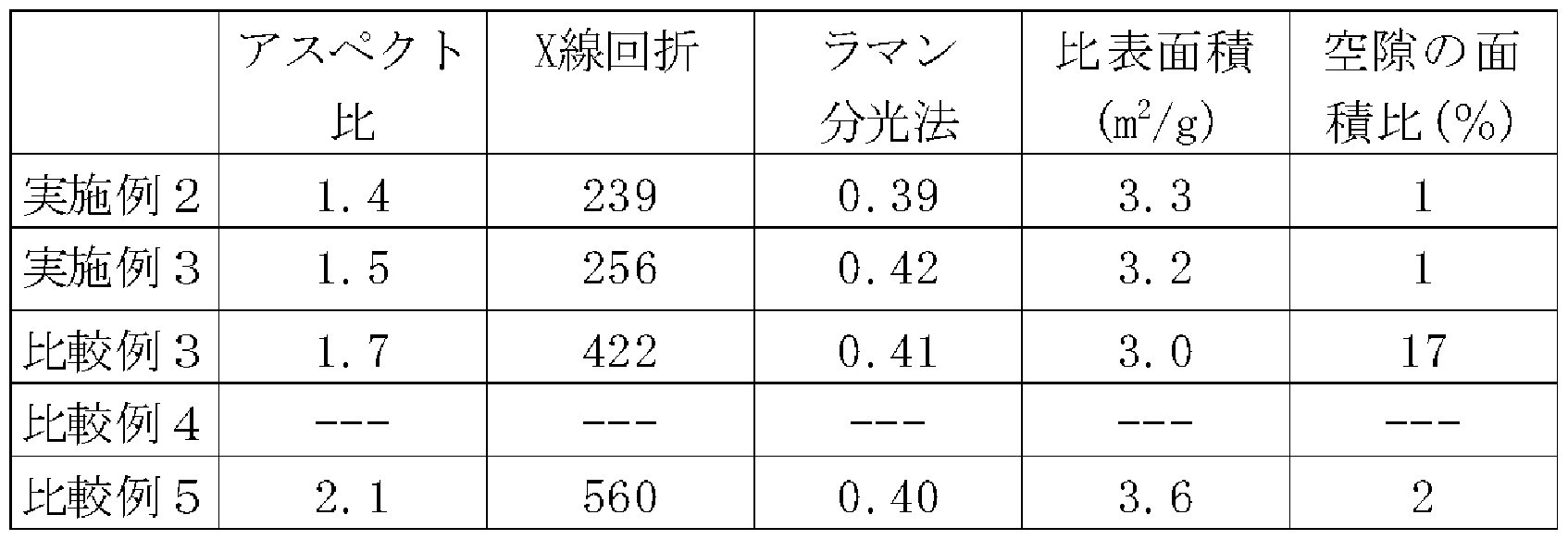
- the carbon graphite composite particles obtained in Examples 2 and 3 had the physical properties of the particles, including the depth of the recesses, within the constitutional range of the present invention.
- the electrode formed using these carbon graphite composite particles was favorably used as a negative electrode for a lithium ion secondary battery, and obtained a positive electrode evaluation.
- the carbon-graphite composite particles obtained in Comparative Examples 3 and 5 had a recess depth that deviated from the constitutional range of the present invention.
- the electrode formed by using these carbon graphite composite particles was not preferable in terms of electrode evaluation as a negative electrode for a lithium ion secondary battery having a low capacity retention rate.
- Comparative Example 6 10 g of spherical graphite (average particle size 26 m) was heat-treated in an electric furnace under a nitrogen stream at 900 ° C. for 20 minutes. The treated particles were collected and subjected to measurements such as tap density, average particle size, SEM observation, carbon coverage, recess depth, electrode density, and electrode evaluation.
- Tables 8 to 10 show the results obtained in Example 4 and Comparative Example 6.
- the graphite particles obtained in Example 4 had the physical properties of the particles, including the depth of the recesses, within the constitutional range of the present invention.
- the electrode formed using these particles obtained favorable electrode evaluation as a negative electrode for a lithium ion secondary battery.
Landscapes
- Chemical & Material Sciences (AREA)
- Engineering & Computer Science (AREA)
- Organic Chemistry (AREA)
- Inorganic Chemistry (AREA)
- Manufacturing & Machinery (AREA)
- Ceramic Engineering (AREA)
- Chemical Kinetics & Catalysis (AREA)
- Electrochemistry (AREA)
- General Chemical & Material Sciences (AREA)
- Materials Engineering (AREA)
- Composite Materials (AREA)
- Structural Engineering (AREA)
- Life Sciences & Earth Sciences (AREA)
- General Life Sciences & Earth Sciences (AREA)
- Geology (AREA)
- Battery Electrode And Active Subsutance (AREA)
- Carbon And Carbon Compounds (AREA)
Abstract
Description


Claims
Priority Applications (6)
| Application Number | Priority Date | Filing Date | Title |
|---|---|---|---|
| DK06834632.9T DK1961701T3 (en) | 2005-12-14 | 2006-12-13 | GRAPHITE PARTICLES, CARBON GRAPHIT COMPOSITION PARTICULARS AND PROCEDURES FOR THEIR MANUFACTURING. |
| EP06834632.9A EP1961701B1 (en) | 2005-12-14 | 2006-12-13 | Graphite particle, carbon-graphite composite particle and their production processes |
| JP2007550209A JP5042854B2 (ja) | 2005-12-14 | 2006-12-13 | 黒鉛粒子、炭素−黒鉛複合粒子及びそれらの製造方法 |
| KR1020087007317A KR101281186B1 (ko) | 2005-12-14 | 2006-12-13 | 흑연입자, 탄소-흑연 복합 입자 및 그 제조 방법 |
| US12/086,432 US8329136B2 (en) | 2005-12-14 | 2006-12-13 | Graphite particle, carbon-graphite composite particle and their production processes |
| CN2006800362877A CN101309859B (zh) | 2005-12-14 | 2006-12-13 | 石墨粒子、碳-石墨复合粒子及其制造方法 |
Applications Claiming Priority (2)
| Application Number | Priority Date | Filing Date | Title |
|---|---|---|---|
| JP2005-360883 | 2005-12-14 | ||
| JP2005360883 | 2005-12-14 |
Publications (1)
| Publication Number | Publication Date |
|---|---|
| WO2007069664A1 true WO2007069664A1 (ja) | 2007-06-21 |
Family
ID=38162967
Family Applications (1)
| Application Number | Title | Priority Date | Filing Date |
|---|---|---|---|
| PCT/JP2006/324877 WO2007069664A1 (ja) | 2005-12-14 | 2006-12-13 | 黒鉛粒子、炭素-黒鉛複合粒子及びそれらの製造方法 |
Country Status (7)
| Country | Link |
|---|---|
| US (1) | US8329136B2 (ja) |
| EP (1) | EP1961701B1 (ja) |
| JP (1) | JP5042854B2 (ja) |
| KR (1) | KR101281186B1 (ja) |
| CN (1) | CN101309859B (ja) |
| DK (1) | DK1961701T3 (ja) |
| WO (1) | WO2007069664A1 (ja) |
Cited By (22)
| Publication number | Priority date | Publication date | Assignee | Title |
|---|---|---|---|---|
| WO2008010312A1 (fr) * | 2006-07-19 | 2008-01-24 | Nippon Carbon Co., Ltd. | Matériau actif pour électrode négative et électrode négative pour batterie rechargeable au lithium ionique |
| JP2009158356A (ja) * | 2007-12-27 | 2009-07-16 | Tokai Carbon Co Ltd | リチウム二次電池の負極材用複合炭素材料及びその製造方法 |
| JP2009181767A (ja) * | 2008-01-30 | 2009-08-13 | Tokai Carbon Co Ltd | リチウム二次電池の負極材用複合炭素材料及びその製造方法 |
| JP2009242196A (ja) * | 2008-03-31 | 2009-10-22 | Ibiden Co Ltd | 黒鉛製弾性体及びその製造方法 |
| JP2010009951A (ja) * | 2008-06-27 | 2010-01-14 | Mitsubishi Chemicals Corp | 非水系二次電池用複合黒鉛粒子、それを含有する負極材料、負極及び非水系二次電池 |
| JP2011060465A (ja) * | 2009-09-07 | 2011-03-24 | Kansai Coke & Chem Co Ltd | リチウムイオン二次電池用黒鉛材料およびその製造方法 |
| WO2011145177A1 (ja) * | 2010-05-18 | 2011-11-24 | トヨタ自動車株式会社 | 負極活物質の評価方法および負極活物質 |
| WO2011145178A1 (ja) * | 2010-05-18 | 2011-11-24 | トヨタ自動車株式会社 | 負極活物質 |
| JP2012523674A (ja) * | 2009-04-13 | 2012-10-04 | エルジー・ケム・リミテッド | リチウム2次電池用負極活物質、その製造方法、及びこれを含むリチウム2次電池 |
| WO2013021443A1 (ja) * | 2011-08-08 | 2013-02-14 | 日立ビークルエナジー株式会社 | 非水電解液二次電池 |
| JP2013179101A (ja) * | 2013-06-28 | 2013-09-09 | Mitsubishi Chemicals Corp | 非水系二次電池用複合黒鉛粒子、それを含有する負極材料、負極及び非水系二次電池 |
| JP2013239352A (ja) * | 2012-05-15 | 2013-11-28 | Toyota Motor Corp | 非水電解質二次電池 |
| JP2014067637A (ja) * | 2012-09-26 | 2014-04-17 | Mitsubishi Chemicals Corp | 非水系二次電池用炭素材、負極及び、非水系二次電池 |
| JP2015053291A (ja) * | 2014-12-01 | 2015-03-19 | 三菱化学株式会社 | リチウムイオン二次電池用黒鉛材料の製造方法、リチウムイオン二次電池用負極およびリチウムイオン二次電池 |
| JP2017532725A (ja) * | 2014-08-29 | 2017-11-02 | 日本電気株式会社 | リチウムイオン電池用の電気化学的に修飾された炭素材料 |
| JP2017533541A (ja) * | 2014-08-29 | 2017-11-09 | 日本電気株式会社 | リチウムイオン電池用アノード材料 |
| JP2018035863A (ja) * | 2016-08-31 | 2018-03-08 | 大同メタル工業株式会社 | 摺動部材 |
| JP2018035864A (ja) * | 2016-08-31 | 2018-03-08 | 大同メタル工業株式会社 | 摺動装置 |
| JP2018514936A (ja) * | 2015-03-27 | 2018-06-07 | 日本電気株式会社 | ボロンドープ活性化炭素材料 |
| CN110491676A (zh) * | 2019-07-29 | 2019-11-22 | 桂林理工大学 | 一种利用多孔碳聚苯胺制备耐高压电极材料的方法 |
| US10629898B2 (en) * | 2009-09-29 | 2020-04-21 | Sila Nanotechnologies Inc. | Electrodes, lithium-ion batteries, and methods of making and using same |
| US11444276B2 (en) | 2019-12-12 | 2022-09-13 | Calb Technology Co., Ltd. | Silicon-graphite composite, preparation method thereof, and lithium battery anode and lithium battery containing silicon-graphite composite |
Families Citing this family (28)
| Publication number | Priority date | Publication date | Assignee | Title |
|---|---|---|---|---|
| WO2006046656A1 (ja) * | 2004-10-28 | 2006-05-04 | Mitsubishi Chemical Corporation | 球状炭素粒子およびその集合体 |
| CL2010000487A1 (es) * | 2010-05-13 | 2011-04-08 | Univ Santiago Chile | Procedimiento para obtener electrodo de carbono desde desechos de pilas acidos que comprende extraer carbon de la pila, sacar recubrimiento, hervir, lavar, lijar y lavar hasta no obtener residuo, sonicar, lavar con solvente altamente apolar, sonicar y lavar con solventes organicos, hervir a ph acido y pulir. |
| WO2012051973A1 (de) | 2010-08-04 | 2012-04-26 | Bayerisches Zentrum Für Angewandte Energieforschung E.V. Zae Bayern | Gross- und offenporiges c/c-komposit mit hoher innerer oberfläche, sowie verfahren zur herstellung desselben und dessen anwendung |
| DE102011108435A1 (de) | 2011-07-26 | 2013-05-02 | Bayerisches Zentrum für Angewandte Energieforschung e.V. | Groß- und offenporiges C/C-Komposit mit hoher innerer Oberfläche, sowie Verfahren zur Herstellung desselben und dessen Anwendung |
| DE102010033380A1 (de) | 2010-08-04 | 2012-02-09 | Bayerisches Zentrum für Angewandte Energieforschung e.V. | Groß- und offenporiges C/C-Komposit mit hoher innerer Oberfläche, sowie Verfahren zur Herstellung desselben und dessen Anwendung |
| DK2650955T3 (da) * | 2010-12-08 | 2016-02-15 | Nippon Coke & Engineering Co Ltd | Negativt elektrodemateriale til lithiumion-sekundærbatterier og fremgangsmåde til fremstilling heraf |
| JP2012133959A (ja) * | 2010-12-21 | 2012-07-12 | Furukawa Battery Co Ltd:The | 鉛蓄電池用複合キャパシタ負極板及び鉛蓄電池 |
| US8679680B2 (en) * | 2011-06-03 | 2014-03-25 | GM Global Technology Operations LLC | Mitigation of mechanical degradation in lithium battery materials using biconcave electrode particles |
| KR20130059472A (ko) * | 2011-11-28 | 2013-06-07 | 삼성에스디아이 주식회사 | 음극 활물질 및 이를 채용한 리튬 전지 |
| JP6510164B2 (ja) * | 2013-03-29 | 2019-05-08 | 株式会社Gsユアサ | 蓄電素子及び車載用蓄電池システム |
| CN104103820B (zh) * | 2013-04-13 | 2017-11-17 | 万台鹏 | 一种锂离子电池球形多孔通道石墨负极材料及其制备方法 |
| CN105144436B (zh) | 2013-07-26 | 2017-04-12 | 株式会社Lg 化学 | 具有提高的能量密度的二次电池用电极和含其的锂二次电池 |
| KR102581550B1 (ko) * | 2014-07-07 | 2023-09-21 | 미쯔비시 케미컬 주식회사 | 탄소재, 탄소재의 제조 방법 및 탄소재를 사용한 비수계 2 차 전지 |
| CN104300111B (zh) * | 2014-10-16 | 2017-02-15 | 佛山市盈通黑金碳材料股份有限公司 | 一种电极材料及其制备方法 |
| KR101854010B1 (ko) * | 2015-03-23 | 2018-05-02 | 주식회사 엘지화학 | 이차 전지용 음극 활물질, 그리고 이를 포함하는 음극, 전극 조립체 및 이차전지 |
| HUE051614T2 (hu) * | 2015-06-15 | 2021-03-01 | Ulsan Nat Inst Science & Tech Unist | Anód aktív anyag másodlagos lítium-akkumulátorokhoz, további elõkészítési módszerekhez, és azonos tartalmú másodlagos lítium-akkumulátorhoz |
| CN108028178A (zh) * | 2015-09-29 | 2018-05-11 | 罗门哈斯电子材料有限责任公司 | 制备石墨碳薄片的方法 |
| TWI552424B (zh) * | 2016-02-01 | 2016-10-01 | 台灣奈米碳素股份有限公司 | 含氮碳電極的製作方法及其液流電池 |
| JP2018006072A (ja) * | 2016-06-29 | 2018-01-11 | オートモーティブエナジーサプライ株式会社 | リチウムイオン二次電池用負極 |
| JP2018006071A (ja) * | 2016-06-29 | 2018-01-11 | オートモーティブエナジーサプライ株式会社 | リチウムイオン二次電池用負極 |
| JP7239277B2 (ja) * | 2017-06-13 | 2023-03-14 | 株式会社イノアック技術研究所 | 導電性発泡体 |
| WO2019226020A1 (ko) * | 2018-05-25 | 2019-11-28 | 주식회사 엘지화학 | 음극 활물질용 복합 입자 및 이를 포함하는 전고체 전지용 음극 |
| CN108933251A (zh) * | 2018-08-29 | 2018-12-04 | 上海市质量监督检验技术研究院 | 一种生物质碳/氧化铁复合材料及其制备方法 |
| CN111244450A (zh) * | 2018-11-29 | 2020-06-05 | 贝特瑞新材料集团股份有限公司 | 天然石墨及由其制备得到的改性天然石墨材料、制备方法和应用 |
| JP7364375B2 (ja) * | 2019-07-12 | 2023-10-18 | イビデン株式会社 | 炭素複合部材 |
| CN113851614A (zh) * | 2020-06-28 | 2021-12-28 | 上海昱瓴新能源科技有限公司 | 低温快充人造石墨负极材料及制备方法和低温快充电池 |
| CN118043991A (zh) * | 2022-08-30 | 2024-05-14 | 宁德新能源科技有限公司 | 负极极片、二次电池和电子装置 |
| CN118032593B (zh) * | 2024-04-10 | 2024-07-23 | 瑞浦兰钧能源股份有限公司 | 一种颗粒辊压粘结强度的评估方法 |
Citations (10)
| Publication number | Priority date | Publication date | Assignee | Title |
|---|---|---|---|---|
| JPH11263612A (ja) * | 1998-03-18 | 1999-09-28 | Kansai Coke & Chem Co Ltd | 鱗片状天然黒鉛改質粒子、その製造法、および二次電池 |
| JP2001063457A (ja) * | 1999-08-30 | 2001-03-13 | Kanto Auto Works Ltd | 自動車の停止表示装置 |
| JP2001213615A (ja) | 2000-01-31 | 2001-08-07 | Mitsui Mining Co Ltd | 圧密化黒鉛粒子、その製造方法、及びリチウム二次電池用負極材料 |
| WO2002059040A1 (fr) * | 2001-01-25 | 2002-08-01 | Hitachi Chemical Co., Ltd. | Particule de graphite artificiel et son procede de production, electrode negative de batterie secondaire a electrolyte non aqueux et son procede de production et batterie secondaire au lithium |
| JP2003238135A (ja) | 2002-02-19 | 2003-08-27 | Mitsui Mining Co Ltd | 球状化黒鉛粒子の製造方法 |
| JP2004111108A (ja) * | 2002-09-13 | 2004-04-08 | Kansai Coke & Chem Co Ltd | 二次電池用電極材料の製法 |
| JP2004111110A (ja) * | 2002-09-13 | 2004-04-08 | Kansai Coke & Chem Co Ltd | 二次電池用電極材料の製法 |
| JP2004196609A (ja) * | 2002-12-19 | 2004-07-15 | Jfe Chemical Corp | 複合黒鉛質粒子の製造方法、複合黒鉛質粒子、リチウムイオン二次電池負極材及びリチウムイオン二次電池 |
| JP2004299944A (ja) * | 2003-03-31 | 2004-10-28 | Jfe Chemical Corp | 黒鉛質粒子、その製造方法、リチウムイオン二次電池およびその負極材料 |
| JP2005123206A (ja) * | 1996-12-26 | 2005-05-12 | Hitachi Chem Co Ltd | リチウム二次電池用負極 |
Family Cites Families (6)
| Publication number | Priority date | Publication date | Assignee | Title |
|---|---|---|---|---|
| JP3873325B2 (ja) * | 1996-07-25 | 2007-01-24 | 大阪瓦斯株式会社 | リチウム二次電池負極用炭素材及びその製造方法 |
| US6344296B1 (en) | 1996-08-08 | 2002-02-05 | Hitachi Chemical Company, Ltd. | Graphite particles and lithium secondary battery using the same as negative electrode |
| JP3635044B2 (ja) * | 2001-06-08 | 2005-03-30 | 三井鉱山株式会社 | リチウム二次電池用負極材料、その製造方法、及びリチウム二次電池 |
| KR100575971B1 (ko) * | 2002-03-27 | 2006-05-02 | 제이에프이 케미칼 가부시키가이샤 | 메소상 소구체의 흑연화물, 그를 사용한 음극 재료, 음극및 리튬 이온 2차 전지 |
| US6841248B2 (en) * | 2002-03-29 | 2005-01-11 | Advanced Energy Technology Inc. | Graphite article comprising a compressed mass of impregnated graphite particles and a reactive lubricant |
| JP2004063457A (ja) * | 2002-06-05 | 2004-02-26 | Mitsubishi Chemicals Corp | 電極用炭素材料の製造方法 |
-
2006
- 2006-12-13 WO PCT/JP2006/324877 patent/WO2007069664A1/ja active Application Filing
- 2006-12-13 CN CN2006800362877A patent/CN101309859B/zh active Active
- 2006-12-13 JP JP2007550209A patent/JP5042854B2/ja not_active Expired - Fee Related
- 2006-12-13 EP EP06834632.9A patent/EP1961701B1/en active Active
- 2006-12-13 US US12/086,432 patent/US8329136B2/en active Active
- 2006-12-13 KR KR1020087007317A patent/KR101281186B1/ko active IP Right Grant
- 2006-12-13 DK DK06834632.9T patent/DK1961701T3/en active
Patent Citations (10)
| Publication number | Priority date | Publication date | Assignee | Title |
|---|---|---|---|---|
| JP2005123206A (ja) * | 1996-12-26 | 2005-05-12 | Hitachi Chem Co Ltd | リチウム二次電池用負極 |
| JPH11263612A (ja) * | 1998-03-18 | 1999-09-28 | Kansai Coke & Chem Co Ltd | 鱗片状天然黒鉛改質粒子、その製造法、および二次電池 |
| JP2001063457A (ja) * | 1999-08-30 | 2001-03-13 | Kanto Auto Works Ltd | 自動車の停止表示装置 |
| JP2001213615A (ja) | 2000-01-31 | 2001-08-07 | Mitsui Mining Co Ltd | 圧密化黒鉛粒子、その製造方法、及びリチウム二次電池用負極材料 |
| WO2002059040A1 (fr) * | 2001-01-25 | 2002-08-01 | Hitachi Chemical Co., Ltd. | Particule de graphite artificiel et son procede de production, electrode negative de batterie secondaire a electrolyte non aqueux et son procede de production et batterie secondaire au lithium |
| JP2003238135A (ja) | 2002-02-19 | 2003-08-27 | Mitsui Mining Co Ltd | 球状化黒鉛粒子の製造方法 |
| JP2004111108A (ja) * | 2002-09-13 | 2004-04-08 | Kansai Coke & Chem Co Ltd | 二次電池用電極材料の製法 |
| JP2004111110A (ja) * | 2002-09-13 | 2004-04-08 | Kansai Coke & Chem Co Ltd | 二次電池用電極材料の製法 |
| JP2004196609A (ja) * | 2002-12-19 | 2004-07-15 | Jfe Chemical Corp | 複合黒鉛質粒子の製造方法、複合黒鉛質粒子、リチウムイオン二次電池負極材及びリチウムイオン二次電池 |
| JP2004299944A (ja) * | 2003-03-31 | 2004-10-28 | Jfe Chemical Corp | 黒鉛質粒子、その製造方法、リチウムイオン二次電池およびその負極材料 |
Non-Patent Citations (1)
| Title |
|---|
| See also references of EP1961701A4 |
Cited By (31)
| Publication number | Priority date | Publication date | Assignee | Title |
|---|---|---|---|---|
| US11276858B2 (en) | 2006-07-19 | 2022-03-15 | Nippon Carbon Co., Ltd. | Negative electrode active material for lithium ion rechargeable battery and negative electrode using the same |
| US10283775B2 (en) | 2006-07-19 | 2019-05-07 | Nippon Carbon Co., Ltd. | Negative electrode active material for lithum ion rechargeable battery and negative electrode using the same |
| WO2008010312A1 (fr) * | 2006-07-19 | 2008-01-24 | Nippon Carbon Co., Ltd. | Matériau actif pour électrode négative et électrode négative pour batterie rechargeable au lithium ionique |
| JP2009158356A (ja) * | 2007-12-27 | 2009-07-16 | Tokai Carbon Co Ltd | リチウム二次電池の負極材用複合炭素材料及びその製造方法 |
| JP2009181767A (ja) * | 2008-01-30 | 2009-08-13 | Tokai Carbon Co Ltd | リチウム二次電池の負極材用複合炭素材料及びその製造方法 |
| JP2009242196A (ja) * | 2008-03-31 | 2009-10-22 | Ibiden Co Ltd | 黒鉛製弾性体及びその製造方法 |
| JP2010009951A (ja) * | 2008-06-27 | 2010-01-14 | Mitsubishi Chemicals Corp | 非水系二次電池用複合黒鉛粒子、それを含有する負極材料、負極及び非水系二次電池 |
| US8669008B2 (en) | 2009-04-13 | 2014-03-11 | Lg Chem, Ltd. | Negative-electrode active material for rechargeable lithium battery |
| JP2012523674A (ja) * | 2009-04-13 | 2012-10-04 | エルジー・ケム・リミテッド | リチウム2次電池用負極活物質、その製造方法、及びこれを含むリチウム2次電池 |
| US9413000B2 (en) | 2009-04-13 | 2016-08-09 | Lg Chem, Ltd. | Negative-electrode active material for rechargeable lithium battery |
| JP2011060465A (ja) * | 2009-09-07 | 2011-03-24 | Kansai Coke & Chem Co Ltd | リチウムイオン二次電池用黒鉛材料およびその製造方法 |
| US10629898B2 (en) * | 2009-09-29 | 2020-04-21 | Sila Nanotechnologies Inc. | Electrodes, lithium-ion batteries, and methods of making and using same |
| JP5527633B2 (ja) * | 2010-05-18 | 2014-06-18 | トヨタ自動車株式会社 | 負極活物質の評価方法および負極活物質 |
| WO2011145177A1 (ja) * | 2010-05-18 | 2011-11-24 | トヨタ自動車株式会社 | 負極活物質の評価方法および負極活物質 |
| WO2011145178A1 (ja) * | 2010-05-18 | 2011-11-24 | トヨタ自動車株式会社 | 負極活物質 |
| KR101432418B1 (ko) | 2010-05-18 | 2014-08-20 | 도요타지도샤가부시키가이샤 | 부극 활물질 |
| JPWO2013021443A1 (ja) * | 2011-08-08 | 2015-03-05 | 日立ビークルエナジー株式会社 | 非水電解液二次電池 |
| WO2013021443A1 (ja) * | 2011-08-08 | 2013-02-14 | 日立ビークルエナジー株式会社 | 非水電解液二次電池 |
| JP2013239352A (ja) * | 2012-05-15 | 2013-11-28 | Toyota Motor Corp | 非水電解質二次電池 |
| JP2014067637A (ja) * | 2012-09-26 | 2014-04-17 | Mitsubishi Chemicals Corp | 非水系二次電池用炭素材、負極及び、非水系二次電池 |
| JP2013179101A (ja) * | 2013-06-28 | 2013-09-09 | Mitsubishi Chemicals Corp | 非水系二次電池用複合黒鉛粒子、それを含有する負極材料、負極及び非水系二次電池 |
| JP2017532725A (ja) * | 2014-08-29 | 2017-11-02 | 日本電気株式会社 | リチウムイオン電池用の電気化学的に修飾された炭素材料 |
| JP2017533541A (ja) * | 2014-08-29 | 2017-11-09 | 日本電気株式会社 | リチウムイオン電池用アノード材料 |
| US10601043B2 (en) | 2014-08-29 | 2020-03-24 | Nec Corporation | Electrochemically modified carbon material for lithium-ion battery |
| US10535876B2 (en) | 2014-08-29 | 2020-01-14 | Nec Corporation | Electrochemically modified carbon material for lithium-ion battery |
| JP2015053291A (ja) * | 2014-12-01 | 2015-03-19 | 三菱化学株式会社 | リチウムイオン二次電池用黒鉛材料の製造方法、リチウムイオン二次電池用負極およびリチウムイオン二次電池 |
| JP2018514936A (ja) * | 2015-03-27 | 2018-06-07 | 日本電気株式会社 | ボロンドープ活性化炭素材料 |
| JP2018035863A (ja) * | 2016-08-31 | 2018-03-08 | 大同メタル工業株式会社 | 摺動部材 |
| JP2018035864A (ja) * | 2016-08-31 | 2018-03-08 | 大同メタル工業株式会社 | 摺動装置 |
| CN110491676A (zh) * | 2019-07-29 | 2019-11-22 | 桂林理工大学 | 一种利用多孔碳聚苯胺制备耐高压电极材料的方法 |
| US11444276B2 (en) | 2019-12-12 | 2022-09-13 | Calb Technology Co., Ltd. | Silicon-graphite composite, preparation method thereof, and lithium battery anode and lithium battery containing silicon-graphite composite |
Also Published As
| Publication number | Publication date |
|---|---|
| CN101309859A (zh) | 2008-11-19 |
| KR101281186B1 (ko) | 2013-07-02 |
| US20090258298A1 (en) | 2009-10-15 |
| EP1961701A1 (en) | 2008-08-27 |
| US8329136B2 (en) | 2012-12-11 |
| EP1961701A4 (en) | 2013-06-12 |
| JP5042854B2 (ja) | 2012-10-03 |
| KR20080075492A (ko) | 2008-08-18 |
| EP1961701B1 (en) | 2017-06-07 |
| JPWO2007069664A1 (ja) | 2009-05-21 |
| CN101309859B (zh) | 2011-03-09 |
| DK1961701T3 (en) | 2017-09-18 |
Similar Documents
| Publication | Publication Date | Title |
|---|---|---|
| JP5042854B2 (ja) | 黒鉛粒子、炭素−黒鉛複合粒子及びそれらの製造方法 | |
| JP5898628B2 (ja) | リチウムイオン二次電池用負極材料及びその製造方法 | |
| US6884545B2 (en) | Anode material for lithium secondary battery, process for production thereof, and lithium secondary battery | |
| KR102324577B1 (ko) | 리튬 이온 2 차 전지용 부극 활물질 및 그 제조 방법 | |
| KR101126425B1 (ko) | 리튬이온 이차전지용 음극재료, 그 제조방법, 리튬이온 이차전지용 음극 및 리튬이온 이차전지 | |
| JP5898572B2 (ja) | 非水電解質二次電池用負極材の製造方法及び非水電解質二次電池の製造方法 | |
| KR100567113B1 (ko) | 리튬이차전지 | |
| CN113169307A (zh) | 用于金属离子电池的电活性材料 | |
| CN113795945B (zh) | 用于金属离子电池的电活性材料 | |
| JP5986347B2 (ja) | リチウムイオン二次電池用黒鉛材料の製造方法 | |
| TW201338253A (zh) | 非水電解質二次電池用碳質材料 | |
| TW201542451A (zh) | 電極用碳質成形體、及其製造方法 | |
| JP4933092B2 (ja) | リチウムイオン二次電池用負極材料、リチウムイオン二次電池用負極およびリチウムイオン二次電池 | |
| US20240120482A1 (en) | Negative electrode material for lithium-ion secondary battery, method of evaluating same, and method of producing same, negative electrode for lithium-ion secondary battery, and lithium-ion secondary battery | |
| KR100793691B1 (ko) | 리튬이온 2차전지용 부극재료, 그 제조방법, 그부극재료를 사용한 리튬이온 2차전지용 부극 및 리튬이온2차전지 | |
| KR102695392B1 (ko) | 리튬 이차전지용 음극 활물질, 이의 제조방법 및 이를 포함하는 리튬 이차전지 | |
| KR20240132111A (ko) | 금속 이온 배터리용 전기활성 물질 |
Legal Events
| Date | Code | Title | Description |
|---|---|---|---|
| WWE | Wipo information: entry into national phase |
Ref document number: 200680036287.7 Country of ref document: CN |
|
| 121 | Ep: the epo has been informed by wipo that ep was designated in this application | ||
| DPE1 | Request for preliminary examination filed after expiration of 19th month from priority date (pct application filed from 20040101) | ||
| ENP | Entry into the national phase |
Ref document number: 2007550209 Country of ref document: JP Kind code of ref document: A |
|
| WWE | Wipo information: entry into national phase |
Ref document number: 1020087007317 Country of ref document: KR |
|
| REEP | Request for entry into the european phase |
Ref document number: 2006834632 Country of ref document: EP |
|
| WWE | Wipo information: entry into national phase |
Ref document number: 12086432 Country of ref document: US Ref document number: 2006834632 Country of ref document: EP |
|
| NENP | Non-entry into the national phase |
Ref country code: DE |