US6836650B2 - Methods and systems for down-converting electromagnetic signals, and applications thereof - Google Patents
Methods and systems for down-converting electromagnetic signals, and applications thereof Download PDFInfo
- Publication number
- US6836650B2 US6836650B2 US10/330,219 US33021902A US6836650B2 US 6836650 B2 US6836650 B2 US 6836650B2 US 33021902 A US33021902 A US 33021902A US 6836650 B2 US6836650 B2 US 6836650B2
- Authority
- US
- United States
- Prior art keywords
- signal
- under
- sampling
- frequency
- carrier
- Prior art date
- Legal status (The legal status is an assumption and is not a legal conclusion. Google has not performed a legal analysis and makes no representation as to the accuracy of the status listed.)
- Expired - Lifetime
Links
Images


Classifications
-
- H—ELECTRICITY
- H04—ELECTRIC COMMUNICATION TECHNIQUE
- H04L—TRANSMISSION OF DIGITAL INFORMATION, e.g. TELEGRAPHIC COMMUNICATION
- H04L27/00—Modulated-carrier systems
- H04L27/32—Carrier systems characterised by combinations of two or more of the types covered by groups H04L27/02, H04L27/10, H04L27/18 or H04L27/26
- H04L27/34—Amplitude- and phase-modulated carrier systems, e.g. quadrature-amplitude modulated carrier systems
- H04L27/38—Demodulator circuits; Receiver circuits
- H04L27/3845—Demodulator circuits; Receiver circuits using non - coherent demodulation, i.e. not using a phase synchronous carrier
- H04L27/3881—Demodulator circuits; Receiver circuits using non - coherent demodulation, i.e. not using a phase synchronous carrier using sampling and digital processing, not including digital systems which imitate heterodyne or homodyne demodulation
-
- H—ELECTRICITY
- H03—ELECTRONIC CIRCUITRY
- H03C—MODULATION
- H03C1/00—Amplitude modulation
- H03C1/62—Modulators in which amplitude of carrier component in output is dependent upon strength of modulating signal, e.g. no carrier output when no modulating signal is present
-
- H—ELECTRICITY
- H03—ELECTRONIC CIRCUITRY
- H03D—DEMODULATION OR TRANSFERENCE OF MODULATION FROM ONE CARRIER TO ANOTHER
- H03D7/00—Transference of modulation from one carrier to another, e.g. frequency-changing
-
- H—ELECTRICITY
- H03—ELECTRONIC CIRCUITRY
- H03D—DEMODULATION OR TRANSFERENCE OF MODULATION FROM ONE CARRIER TO ANOTHER
- H03D7/00—Transference of modulation from one carrier to another, e.g. frequency-changing
- H03D7/14—Balanced arrangements
- H03D7/1425—Balanced arrangements with transistors
- H03D7/1441—Balanced arrangements with transistors using field-effect transistors
-
- H—ELECTRICITY
- H03—ELECTRONIC CIRCUITRY
- H03D—DEMODULATION OR TRANSFERENCE OF MODULATION FROM ONE CARRIER TO ANOTHER
- H03D7/00—Transference of modulation from one carrier to another, e.g. frequency-changing
- H03D7/14—Balanced arrangements
- H03D7/1425—Balanced arrangements with transistors
- H03D7/1475—Subharmonic mixer arrangements
-
- H—ELECTRICITY
- H04—ELECTRIC COMMUNICATION TECHNIQUE
- H04B—TRANSMISSION
- H04B1/00—Details of transmission systems, not covered by a single one of groups H04B3/00 - H04B13/00; Details of transmission systems not characterised by the medium used for transmission
- H04B1/0003—Software-defined radio [SDR] systems, i.e. systems wherein components typically implemented in hardware, e.g. filters or modulators/demodulators, are implented using software, e.g. by involving an AD or DA conversion stage such that at least part of the signal processing is performed in the digital domain
- H04B1/0007—Software-defined radio [SDR] systems, i.e. systems wherein components typically implemented in hardware, e.g. filters or modulators/demodulators, are implented using software, e.g. by involving an AD or DA conversion stage such that at least part of the signal processing is performed in the digital domain wherein the AD/DA conversion occurs at radiofrequency or intermediate frequency stage
- H04B1/0025—Software-defined radio [SDR] systems, i.e. systems wherein components typically implemented in hardware, e.g. filters or modulators/demodulators, are implented using software, e.g. by involving an AD or DA conversion stage such that at least part of the signal processing is performed in the digital domain wherein the AD/DA conversion occurs at radiofrequency or intermediate frequency stage using a sampling rate lower than twice the highest frequency component of the sampled signal
-
- H—ELECTRICITY
- H04—ELECTRIC COMMUNICATION TECHNIQUE
- H04B—TRANSMISSION
- H04B1/00—Details of transmission systems, not covered by a single one of groups H04B3/00 - H04B13/00; Details of transmission systems not characterised by the medium used for transmission
- H04B1/06—Receivers
- H04B1/16—Circuits
- H04B1/26—Circuits for superheterodyne receivers
- H04B1/28—Circuits for superheterodyne receivers the receiver comprising at least one semiconductor device having three or more electrodes
-
- H—ELECTRICITY
- H04—ELECTRIC COMMUNICATION TECHNIQUE
- H04B—TRANSMISSION
- H04B7/00—Radio transmission systems, i.e. using radiation field
- H04B7/02—Diversity systems; Multi-antenna system, i.e. transmission or reception using multiple antennas
- H04B7/12—Frequency diversity
-
- H—ELECTRICITY
- H04—ELECTRIC COMMUNICATION TECHNIQUE
- H04L—TRANSMISSION OF DIGITAL INFORMATION, e.g. TELEGRAPHIC COMMUNICATION
- H04L25/00—Baseband systems
- H04L25/02—Details ; arrangements for supplying electrical power along data transmission lines
- H04L25/08—Modifications for reducing interference; Modifications for reducing effects due to line faults ; Receiver end arrangements for detecting or overcoming line faults
-
- H—ELECTRICITY
- H04—ELECTRIC COMMUNICATION TECHNIQUE
- H04L—TRANSMISSION OF DIGITAL INFORMATION, e.g. TELEGRAPHIC COMMUNICATION
- H04L27/00—Modulated-carrier systems
-
- H—ELECTRICITY
- H04—ELECTRIC COMMUNICATION TECHNIQUE
- H04L—TRANSMISSION OF DIGITAL INFORMATION, e.g. TELEGRAPHIC COMMUNICATION
- H04L27/00—Modulated-carrier systems
- H04L27/02—Amplitude-modulated carrier systems, e.g. using on-off keying; Single sideband or vestigial sideband modulation
- H04L27/06—Demodulator circuits; Receiver circuits
-
- H—ELECTRICITY
- H04—ELECTRIC COMMUNICATION TECHNIQUE
- H04L—TRANSMISSION OF DIGITAL INFORMATION, e.g. TELEGRAPHIC COMMUNICATION
- H04L27/00—Modulated-carrier systems
- H04L27/10—Frequency-modulated carrier systems, i.e. using frequency-shift keying
- H04L27/12—Modulator circuits; Transmitter circuits
-
- H—ELECTRICITY
- H04—ELECTRIC COMMUNICATION TECHNIQUE
- H04L—TRANSMISSION OF DIGITAL INFORMATION, e.g. TELEGRAPHIC COMMUNICATION
- H04L27/00—Modulated-carrier systems
- H04L27/10—Frequency-modulated carrier systems, i.e. using frequency-shift keying
- H04L27/14—Demodulator circuits; Receiver circuits
- H04L27/144—Demodulator circuits; Receiver circuits with demodulation using spectral properties of the received signal, e.g. by using frequency selective- or frequency sensitive elements
- H04L27/148—Demodulator circuits; Receiver circuits with demodulation using spectral properties of the received signal, e.g. by using frequency selective- or frequency sensitive elements using filters, including PLL-type filters
-
- H—ELECTRICITY
- H04—ELECTRIC COMMUNICATION TECHNIQUE
- H04L—TRANSMISSION OF DIGITAL INFORMATION, e.g. TELEGRAPHIC COMMUNICATION
- H04L27/00—Modulated-carrier systems
- H04L27/10—Frequency-modulated carrier systems, i.e. using frequency-shift keying
- H04L27/14—Demodulator circuits; Receiver circuits
- H04L27/156—Demodulator circuits; Receiver circuits with demodulation using temporal properties of the received signal, e.g. detecting pulse width
-
- H—ELECTRICITY
- H04—ELECTRIC COMMUNICATION TECHNIQUE
- H04L—TRANSMISSION OF DIGITAL INFORMATION, e.g. TELEGRAPHIC COMMUNICATION
- H04L27/00—Modulated-carrier systems
- H04L27/26—Systems using multi-frequency codes
- H04L27/2601—Multicarrier modulation systems
- H04L27/2647—Arrangements specific to the receiver only
- H04L27/2655—Synchronisation arrangements
- H04L27/2668—Details of algorithms
- H04L27/2669—Details of algorithms characterised by the domain of operation
- H04L27/2672—Frequency domain
Definitions
- the present invention relates to down-conversion of electromagnetic (EM) signals. More particularly, the present invention relates to down-conversion of EM signals to intermediate frequency signals, to direct down-conversion of EM modulated carrier signals to demodulated baseband signals, and to conversion of FM signals to non-FM signals.
- the present invention also relates to under-sampling and to transferring energy at aliasing rates.
- Electromagnetic (EM) information signals include, but are not limited to, video baseband signals, voice baseband signals, computer baseband signals, etc.
- Baseband signals include analog baseband signals and digital baseband signals.
- Up-conversion to a higher frequency is utilized.
- Conventional up-conversion processes modulate higher frequency carrier signals with baseband signals. Modulation refers to a variety of techniques for impressing information from the baseband signals onto the higher frequency carrier signals. The resultant signals are referred to herein as modulated carrier signals.
- the amplitude of an AM carrier signal varies in relation to changes in the baseband signal
- the frequency of an FM carrier signal varies in relation to changes in the baseband signal
- the phase of a PM carrier signal varies in relation to changes in the baseband signal.
- the information In order to process the information that was in the baseband signal, the information must be extracted, or demodulated, from the modulated carrier signal.
- conventional signal processing technology is limited in operational speed, conventional signal processing technology cannot easily demodulate a baseband signal from higher frequency modulated carrier signal directly. Instead, higher frequency modulated carrier signals must be down-converted to an intermediate frequency (IF), from where a conventional demodulator can demodulate the baseband signal.
- IF intermediate frequency
- Conventional down-converters include electrical components whose properties are frequency dependent. As a result, conventional down-converters are designed around specific frequencies or frequency ranges and do not work well outside their designed frequency range.
- Conventional down-converters generate unwanted image signals and thus must include filters for filtering the unwanted image signals.
- filters reduce the power level of the modulated carrier signals.
- conventional down-converters include power amplifiers, which require external energy sources.
- conventional down-converters When a received modulated carrier signal is relatively weak, as in, for example, a radio receiver, conventional down-converters include additional power amplifiers, which require additional external energy.
- the present invention is directed to methods, systems, and apparatuses for down-converting an electromagnetic (EM) signal by aliasing the EM signal, and applications thereof.
- the invention operates by receiving an EM signal.
- the invention also receives an aliasing signal having an aliasing rate.
- the invention aliases the EM signal according to the aliasing signal to down-convert the EM signal.
- aliasing refers to both down-converting an EM signal by under-sampling the EM signal at an aliasing rate, and down-converting an EM signal by transferring energy from the EM signal at the aliasing rate.
- the invention down-converts the EM signal to an intermediate frequency (IF) signal.
- IF intermediate frequency
- the invention down-converts the EM signal to a demodulated baseband information signal.
- the EM signal is a frequency modulated (FM) signal, which is down-converted to a non-FM signal, such as a phase modulated (PM) signal or an amplitude modulated (AM) signal.
- FM frequency modulated
- AM amplitude modulated
- the invention is applicable to any type of EM signal, including but not limited to, modulated carrier signals (the invention is applicable to any modulation scheme or combination thereof) and unmodulated carrier signals.
- FIG. 1 illustrates a structural block diagram of an example modulator
- FIG. 2 illustrates an example analog modulating baseband signal
- FIG. 3 illustrates an example digital modulating baseband signal
- FIG. 4 illustrates an example carrier signal
- FIGS. 5A-5C illustrate example signal diagrams related to amplitude modulation
- FIGS. 6A-6C illustrate example signal diagrams related to amplitude shift keying modulation
- FIGS. 7A-7C illustrate example signal diagrams related to frequency modulation
- FIGS. 8A-8C illustrate example signal diagrams related to frequency shift keying modulation
- FIGS. 9A-9C illustrate example signal diagrams related to phase modulation
- FIGS. 10A-10C illustrate example signal diagrams related to phase shift keying modulation
- FIG. 11 illustrates a structural block diagram of a conventional receiver
- FIGS. 12A-D illustrate various flowcharts for down-converting an EM-signal according to embodiments of the invention
- FIG. 13 illustrates a structural block diagram of an aliasing system according to an embodiment of the invention
- FIGS. 14A-D illustrate various flowcharts for down-converting an EM signal by under-sampling the EM signal according to embodiments of the invention
- FIGS. 15A-E illustrate example signal diagrams associated with flowcharts in FIGS. 14A-D according to embodiments of the invention
- FIG. 16 illustrates a structural block diagram of an under-sampling system according to an embodiment of the invention
- FIG. 17 illustrates a flowchart of an example process for determining an aliasing rate according to an embodiment of the invention
- FIGS. 18A-E illustrate example signal diagrams associated with down-converting a digital AM signal to an intermediate frequency signal by under-sampling according to embodiments of the invention
- FIGS. 19A-E illustrate example signal diagrams associated with down-converting an analog AM signal to an intermediate frequency signal by under-sampling according to embodiments of the invention
- FIGS. 20A-E illustrate example signal diagrams associated with down-converting an analog FM signal to an intermediate frequency signal by under-sampling according to embodiments of the invention
- FIGS. 21A-E illustrate example signal diagrams associated with down-converting a digital FM signal to an intermediate frequency signal by under-sampling according to embodiments of the invention
- FIGS. 22A-E illustrate example signal diagrams associated with down-converting a digital PM signal to an intermediate frequency signal by under-sampling according to embodiments of the invention
- FIGS. 23A-E illustrate example signal diagrams associated with down-converting an analog PM signal to an intermediate frequency signal by under-sampling according to embodiments of the invention
- FIG. 24A illustrates a structural block diagram of a make before break under-sampling system according to an embodiment of the invention
- FIG. 24B illustrates an example timing diagram of an under sampling signal according to an embodiment of the invention
- FIG. 24C illustrates an example timing diagram of an isolation signal according to an embodiment of the invention.
- FIGS. 25A-H illustrate example aliasing signals at various aliasing rates according to embodiments of the invention
- FIG. 26A illustrates a structural block diagram of an exemplary sample and hold system according to an embodiment of the invention
- FIG. 26B illustrates a structural block diagram of an exemplary inverted sample and hold system according to an embodiment of the invention
- FIG. 27 illustrates a structural block diagram of sample and hold module according to an embodiment of the invention
- FIGS. 28A-D illustrate example implementations of a switch module according to embodiments of the invention.
- FIGS. 29A-F illustrate example implementations of a holding module according to embodiments of the present invention.
- FIG. 29G illustrates an integrated under-sampling system according to embodiments of the invention.
- FIGS. 29H-K illustrate example implementations of pulse generators according to embodiments of the invention.
- FIG. 29L illustrates an example oscillator
- FIG. 30 illustrates a structural block diagram of an under-sampling system with an under-sampling signal optimizer according to embodiments of the invention
- FIG. 31 illustrates a structural block diagram of an under-sampling signal optimizer according to embodiments of the present invention
- FIG. 32A illustrates an example of an under-sampling signal module according to an embodiment of the invention
- FIG. 32B illustrates a flowchart of a state machine operation associated with an under-sampling module according to embodiments of the invention
- FIG. 32C illustrates an example under-sampling module that includes an analog circuit with automatic gain control according to embodiments of the invention
- FIGS. 33A-D illustrate example signal diagrams associated with direct down-conversion of an EM signal to a baseband signal by under-sampling according to embodiments of the present invention
- FIGS. 34A-F illustrate example signal diagrams associated with an inverted sample and hold module according to embodiments of the invention
- FIGS. 35A-E illustrate example signal diagrams associated with directly down-converting an analog AM signal to a demodulated baseband signal by under-sampling according to embodiments of the invention
- FIGS. 36A-E illustrate example signal diagrams associated with down-converting a digital AM signal to a demodulated baseband signal by under-sampling according to embodiments of the invention
- FIGS. 37A-E illustrate example signal diagrams associated with directly down-converting an analog PM signal to a demodulated baseband signal by under-sampling according to embodiments of the invention
- FIGS. 38A-E illustrate example signal diagrams associated with down-converting a digital PM signal to a demodulated baseband signal by under-sampling according to embodiments of the invention
- FIGS. 39A-D illustrate down-converting a FM signal to a non-FM signal by under-sampling according to embodiments of the invention
- FIGS. 40A-E illustrate down-converting a FSK signal to a PSK signal by under-sampling according to embodiments of the invention
- FIGS. 41A-E illustrate down-converting a FSK signal to an ASK signal by under-sampling according to embodiments of the invention
- FIG. 42 illustrates a structural block diagram of an inverted sample and hold module according to an embodiment of the present invention
- FIGS. 43A and 43B illustrate example waveforms present in the circuit of FIG. 31;
- FIG. 44A illustrates a structural block diagram of a differential system according to embodiments of the invention.
- FIG. 44B illustrates a structural block diagram of a differential system with a differential input and a differential output according to embodiments of the invention
- FIG. 44C illustrates a structural block diagram of a differential system with a single input and a differential output according to embodiments of the invention
- FIG. 44D illustrates a differential input with a single output according to embodiments of the invention
- FIG. 44E illustrates an example differential input to single output system according to embodiments of the invention.
- FIGS. 45A-B illustrate a conceptual illustration of aliasing including under-sampling and energy transfer according to embodiments of the invention
- FIGS. 46A-D illustrate various flowchart for down-converting an EM signal by transferring energy from the EM signal at an aliasing rate according to embodiments of the invention
- FIGS. 47A-E illustrate example signal diagrams associated with the flowcharts in FIGS. 46A-D according to embodiments of the invention
- FIG. 48 is a flowchart that illustrates an example process for determining an aliasing rate associated with an aliasing signal according to an embodiment of the invention
- FIGS. 49A-H illustrate example energy transfer signals according to embodiments of the invention.
- FIGS. 50A-G illustrate example signal diagrams associated with down-converting an analog AM signal to an intermediate frequency by transferring energy at an aliasing rate according to embodiments of the invention
- FIGS. 51A-G illustrate example signal diagrams associated with down-converting an digital AM signal to an intermediate frequency by transferring energy at an aliasing rate according to embodiments of the invention
- FIGS. 52A-G illustrate example signal diagrams associated with down-converting an analog FM signal to an intermediate frequency by transferring energy at an aliasing rate according to embodiments of the invention
- FIGS. 53A-G illustrate example signal diagrams associated with down-converting an digital FM signal to an intermediate frequency by transferring energy at an aliasing rate according to embodiments of the invention
- FIGS. 54A-G illustrate example signal diagrams associated with down-converting an analog PM signal to an intermediate frequency by transferring energy at an aliasing rate according to embodiments of the invention
- FIGS. 55A-G illustrate example signal diagrams associated with down-converting an digital PM signal to an intermediate frequency by transferring energy at an aliasing rate according to embodiments of the invention
- FIGS. 56A-D illustrate an example signal diagram associated with direct down-conversion according to embodiments of the invention
- FIGS. 57A-F illustrate directly down-converting an analog AM signal to a demodulated baseband signal according to embodiments of the invention
- FIGS. 58A-F illustrate directly down-converting an digital AM signal to a demodulated baseband signal according to embodiments of the invention
- FIGS. 59A-F illustrate directly down-converting an analog PM signal to a demodulated baseband signal according to embodiments of the invention
- FIGS. 60A-F illustrate directly down-converting an digital PM signal to a demodulated baseband signal according to embodiments of the invention
- FIGS. 61A-F illustrate down-converting an FM signal to a PM signal according to embodiments of the invention
- FIGS. 62A-F illustrate down-converting an FM signal to a AM signal according to embodiments of the invention
- FIG. 63 illustrates a block diagram of an energy transfer system according to an embodiment of the invention.
- FIG. 64A illustrates an exemplary gated transfer system according to an embodiment of the invention
- FIG. 64B illustrates an exemplary inverted gated transfer system according to an embodiment of the invention
- FIG. 65 illustrates an example embodiment of the gated transfer module according to an embodiment of the invention.
- FIGS. 66A-D illustrate example implementations of a switch module according to embodiments of the invention.
- FIG. 67A illustrates an example embodiment of the gated transfer module as including a break-before-make module according to an embodiment of the invention
- FIG. 67B illustrates an example timing diagram for an energy transfer signal according to an embodiment of the invention
- FIG. 67C illustrates an example timing diagram for an isolation signal according to an embodiment of the invention.
- FIGS. 68A-F illustrate example storage modules according to embodiments of the invention.
- FIG. 68G illustrates an integrated gated transfer system according to an embodiment of the invention
- FIGS. 68H-K illustrate example aperture generators
- FIG. 68L illustrates an oscillator according to an embodiment of the present invention
- FIG. 69 illustrates an energy transfer system with an optional energy transfer signal module according to an embodiment of the invention
- FIG. 70 illustrates an aliasing module with input and output impedance match according to an embodiment of the invention
- FIG. 71 illustrates an example pulse generator
- FIGS. 72A and 72B illustrate example waveforms related to the pulse generator of FIG. 71;
- FIG. 73 illustrates an example energy transfer module with a switch module and a reactive storage module according to an embodiment of the invention
- FIG. 74 illustrates an example inverted gated transfer module as including a switch module and a storage module according to an embodiment of the invention
- FIGS. 75A-F illustrate an example signal diagrams associated with an inverted gated energy transfer module according to embodiments of the invention.
- FIGS. 76A-E illustrate energy transfer modules in configured in various differential configurations according to embodiments of the invention.
- FIGS. 77A-C illustrate example impedance matching circuits according to embodiments of the invention.
- FIGS. 78A-B illustrate example under-sampling systems according to embodiments of the invention.
- FIGS. 79A-F illustrate example timing diagrams for under-sampling systems according to embodiments of the invention.
- FIGS. 80A-F illustrate example timing diagrams for an under-sampling system when the load is a relatively low impedance load according to embodiments of the invention
- FIGS. 81A-F illustrate example timing diagrams for an under-sampling system when the holding capacitance has a larger value according to embodiments of the invention
- FIGS. 82A-B illustrate example energy transfer systems according to embodiments of the invention.
- FIGS. 83A-F illustrate example timing diagrams for energy transfer systems according to embodiments of the present invention.
- FIGS. 84A-D illustrate down-converting an FSK signal to a PSK signal according to embodiments of the present invention
- FIG. 85A illustrates an example energy transfer signal module according to an embodiment of the present invention
- FIG. 85B illustrates a flowchart of state machine operation according to an embodiment of the present invention.
- FIG. 85C is an example energy transfer signal module
- FIG. 86 is a schematic diagram of a circuit to down-convert a 915 MHZ signal to a 5 MHZ signal using a 101.1 MHZ clock according to an embodiment of the present invention
- FIG. 87 shows simulation waveforms for the circuit of FIG. 86 according to embodiments of the present invention.
- FIG. 88 is a schematic diagram of a circuit to down-convert a 915 MHZ signal to a 5 MHz signal using a 101 MHZ clock according to an embodiment of the present invention
- FIG. 89 shows simulation waveforms for the circuit of FIG. 88 according to embodiments of the present invention.
- FIG. 90 is a schematic diagram of a circuit to down-convert a 915 MHZ signal to a 5 MHZ signal using a 101.1 MHZ clock according to an embodiment of the present invention
- FIG. 91 shows simulation waveforms for the circuit of FIG. 90 according to an embodiment of the present invention.
- FIG. 92 shows a schematic of the circuit in FIG. 86 connected to an FSK source that alternates between 913 and 917 MHZ at a baud rate of 500 Kbaud according to an embodiment of the present invention
- FIG. 93 shows the original FSK waveform 9202 and the down-converted waveform 9204 at the output of the load impedance match circuit according to an embodiment of the present invention
- FIG. 94A illustrates an example energy transfer system according to an embodiment of the invention
- FIGS. 94B-C illustrate example timing diagrams for the example system of FIG. 94A
- FIG. 95 illustrates an example bypass network according to an embodiment of the invention.
- FIG. 96 illustrates an example bypass network according to an embodiment of the invention
- FIG. 97 illustrates an example embodiment of the invention
- FIG. 98A illustrates an example real time aperture control circuit according to an embodiment of the invention
- FIG. 98B illustrates a timing diagram of an example clock signal for real time aperture control, according to an embodiment of the invention.
- FIG. 98C illustrates a timing diagram of an example optional enable signal for real time aperture control, according to an embodiment of the invention.
- FIG. 98D illustrates a timing diagram of an inverted clock signal for real time aperture control, according to an embodiment of the invention.
- FIG. 98E illustrates a timing diagram of an example delayed clock signal for real time aperture control, according to an embodiment of the invention.
- FIG. 98F illustrates a timing diagram of an example energy transfer module including pulses having apertures that are controlled in real time, according to an embodiment of the invention
- FIG. 99 is a block diagram of a differential system that utilizes non-inverted gated transfer units, according to an embodiment of the invention.
- FIG. 100 illustrates an example embodiment of the invention
- FIG. 101 illustrates an example embodiment of the invention
- FIG. 102 illustrates an example embodiment of the invention
- FIG. 103 illustrates an example embodiment of the invention
- FIG. 104 illustrates an example embodiment of the invention
- FIG. 105 illustrates an example embodiment of the invention
- FIG. 106 illustrates an example embodiment of the invention
- FIG. 107A is a timing diagram for the example embodiment of FIG. 103;
- FIG. 107B is a timing diagram for the example embodiment of FIG. 104;
- FIG. 108A is a timing diagram for the example embodiment of FIG. 105;
- FIG. 108B is a timing diagram for the example embodiment of FIG. 106;
- FIG. 109A illustrates and example embodiment of the invention
- FIG. 109B illustrates equations for determining charge transfer, in accordance with the present invention.
- FIG. 109C illustrates relationships between capacitor charging and aperture, in accordance with the present invention.
- FIG. 109D illustrates relationships between capacitor charging and aperture, in accordance with the present invention.
- FIG. 109E illustrates power-charge relationship equations, in accordance with the present invention.
- FIG. 109F illustrates insertion loss equations, in accordance with the present invention.
- FIG. 110A illustrates aliasing module 11000 a single FET configuration
- FIG. 110B illustrates FET conductivity vs. V GS ;
- FIGS. 111A-C illustrate signal waveforms associated with aliasing module 11000 ;
- FIG. 112 illustrates aliasing module 11200 with a complementary FET configuration
- FIGS. 113A-E illustrate signal waveforms associated with aliasing module 11200 ;
- FIG. 114 illustrates aliasing module 11400
- FIG. 115 illustrates aliasing module 11500
- FIG. 116 illustrates aliasing module 11602
- FIG. 117 illustrates aliasing module 11702
- FIGS. 118-120 illustrate signal waveforms associated with aliasing module 11602 ;
- FIGS. 121-123 illustrate signal waveforms associated with aliasing module 11702 .
- FIG. 124A is a block diagram of a splitter according to an embodiment of the invention.
- FIG. 124B is a more detailed diagram of a splitter according to an embodiment of the invention.
- FIGS. 124C and 124D are example waveforms related to the splitter of FIGS. 124A and 124B;
- FIG. 124E is a block diagram of an I/Q circuit with a splitter according to an embodiment of the invention.
- FIGS. 124F-124J are example waveforms related to the diagram of FIG. 124A;
- FIG. 125 is a block diagram of a switch module according to an embodiment of the invention.
- FIG. 126A is an implementation example of the block diagram of FIG. 125;
- FIGS. 126B-126Q are example waveforms related to FIG. 126A;
- FIG. 127A is another implementation example of the block diagram of FIG. 125;
- FIGS. 127B-127Q are example waveforms related to FIG. 127A;
- FIG. 128A is an example MOSFET embodiment of the invention.
- FIG. 128B is an example MOSFET embodiment of the invention.
- FIG. 128C is an example MOSFET embodiment of the invention.
- FIG. 129A is another implementation example of the block diagram of FIG. 125;
- FIGS. 129B-129Q are example waveforms related to FIG. 127A;
- FIGS. 130 and 131 illustrate the amplitude and pulse width modulated transmitter according to embodiments of the present invention
- FIGS. 132A-132D illustrate example signal diagrams associated with the amplitude and pulse width modulated transmitter according to embodiments of the present invention
- FIG. 133 illustrates an example diagram associated with the amplitude and pulse width modulated transmitter according to embodiments of the present invention
- FIG. 134 illustrates and example diagram associated with the amplitude and pulse width modulated transmitter according to embodiments of the present invention
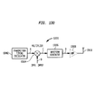
- FIG. 135 shows an embodiment of a receiver block diagram to recover the amplitude or pulse width modulated information
- FIGS. 136A-136G illustrate example signal diagrams associated with a waveform generator according to embodiments of the present invention
- FIGS. 137-139 are example schematic diagrams illustrating various circuits employed in the receiver of FIG. 135;
- FIGS. 140-143 illustrate time and frequency domain diagrams of alternative transmitter output waveforms
- FIGS. 144 and 145 illustrate differential receivers in accord with embodiments of the present invention.
- FIGS. 146 and 147 illustrate time and frequency domains for a narrow bandwidth/constant carrier signal in accord with an embodiment of the present invention.
- flowcharts such as flowchart 1201 in FIG. 12 A.
- flowchart 1201 the operation of the invention is often represented by flowcharts, such as flowchart 1201 in FIG. 12 A.
- flowcharts the use of flowcharts is for illustrative purposes only, and is not limiting.
- the invention is not limited to the operational embodiment(s) represented by the flowcharts. Instead, alternative operational embodiments will be apparent to persons skilled in the relevant art(s) based on the discussion contained herein.
- the use of flowcharts should not be interpreted as limiting the invention to discrete or digital operation. In practice, as will be appreciated by persons skilled in the relevant art(s) based on the herein discussion, the invention can be achieved via discrete or continuous operation, or a combination thereof.
- modulated carrier signal when used herein, refers to a carrier signal that is modulated by a baseband signal.
- unmodulated carrier signal when used herein, refers to a signal having an amplitude that oscillates at a substantially uniform frequency and phase.
- baseband signal when used herein, refers to an information signal including, but not limited to, analog information signals, digital information signals and direct current (DC) information signals.
- carrier signal when used herein, and unless otherwise specified when used herein, refers to modulated carrier signals and unmodulated carrier signals.
- electromagnetic (EM) signal when used herein, refers to a signal in the EM spectrum.
- EM spectrum includes all frequencies greater than zero hertz.
- EM signals generally include waves characterized by variations in electric and magnetic fields. Such waves may be propagated in any medium, both natural and manmade, including but not limited to air, space, wire, cable, liquid, waveguide, micro-strip, strip-line, optical fiber, etc. Unless stated otherwise, all signals discussed herein are EM signals, even when not explicitly designated as such.
- intermediate frequency (IF) signal when used herein, refers to an EM signal that is substantially similar to another EM signal except that the IF signal has a lower frequency than the other signal.
- An IF signal frequency can be any frequency above zero HZ. Unless otherwise stated, the terms lower frequency, intermediate frequency, intermediate and IF are used interchangeably herein.
- analog signal when used herein, refers to a signal that is constant or continuously variable, as contrasted to a signal that changes between discrete states.
- baseband when used herein, refers to a frequency band occupied by any generic information signal desired for transmission and/or reception.
- baseband signal when used herein, refers to any generic information signal desired for transmission and/or reception.
- carrier frequency when used herein, refers to the frequency of a carrier signal. Typically, it is the center frequency of a transmission signal that is generally modulated.
- carrier signal when used herein, refers to an EM wave having at least one characteristic that may be varied by modulation, that is capable of carrying information via modulation.
- demodulated baseband signal when used herein, refers to a signal that results from processing a modulated signal.
- the demodulated baseband signal results from demodulating an intermediate frequency (IF) modulated signal, which results from down converting a modulated carrier signal.
- IF intermediate frequency
- a signal that results from a combined downconversion and demodulation step a signal that results from a combined downconversion and demodulation step.
- digital signal when used herein, refers to a signal that changes between discrete states, as contrasted to a signal that is continuous. For example, the voltage of a digital signal may shift between discrete levels.
- electromagnetic (EM) spectrum when used herein, refers to a spectrum comprising waves characterized by variations in electric and magnetic fields. Such waves may be propagated in any communication medium, both natural and manmade, including but not limited to air, space, wire, cable, liquid, waveguide, microstrip, stripline, optical fiber, etc.
- the EM spectrum includes all frequencies greater than zero hertz.
- electromagnetic (EM) signal when used herein, refers to a signal in the EM spectrum. Also generally called an EM wave. Unless stated otherwise, all signals discussed herein are EM signals, even when not explicitly designated as such.
- modulating baseband signal when used herein, refers to any generic information signal that is used to modulate an oscillating signal, or carrier signal.
- EM electromagnetic
- baseband signals such as digital data information signals and analog information signals.
- a baseband signal can be up-converted to a higher frequency EM signal by using the baseband signal to modulate a higher frequency carrier signal, F C .
- F C carrier signal
- a modulating baseband signal F MB When used in this manner, such a baseband signal is herein called a modulating baseband signal F MB .
- Modulation imparts changes to the carrier signal F C that represent information in the modulating baseband signal F MB .
- the changes can be in the form of amplitude changes, frequency changes, phase changes, etc., or any combination thereof.
- the resultant signal is referred to herein as a modulated carrier signal F MC .
- the modulated carrier signal F MC includes the carrier signal F C modulated by the modulating baseband signal, F MB , as in:
- the modulated carrier signal F MC oscillates at, or near the frequency of the carrier signal F C and can thus be efficiently propagated.
- FIG. 1 illustrates an example modulator 110 , wherein the carrier signal F C is modulated by the modulating baseband signal F MB , thereby generating the modulated carrier signal F MC .
- Modulating baseband signal F MB can be an analog baseband signal, a digital baseband signal, or a combination thereof.
- FIG. 2 illustrates the modulating baseband signal F MB as an exemplary analog modulating baseband signal 210 .
- the exemplary analog modulating baseband signal 210 can represent any type of analog information including, but not limited to, voice/speech data, music data, video data, etc.
- the amplitude of analog modulating baseband signal 210 varies in time.
- Digital information includes a plurality of discrete states. For ease of explanation, digital information signals are discussed below as having two discrete states. But the invention is not limited to this embodiment.
- FIG. 3 illustrates the modulating baseband signal F MB as an exemplary digital modulating baseband signal 310 .
- the digital modulating baseband signal 310 can represent any type of digital data including, but not limited to, digital computer information and digitized analog information.
- the digital modulating baseband signal 310 includes a first state 312 and a second state 314 .
- first state 312 represents binary state 0 and second state 314 represents binary state 1.
- first state 312 represents binary state 1 and second state 314 represents binary state 0.
- the former convention is followed, whereby first state 312 represents binary state zero and second state 314 represents binary state one. But the invention is not limited to this embodiment.
- First state 312 is thus referred to herein as a low state and second state 314 is referred to herein as a high state.
- Digital modulating baseband signal 310 can change between first state 312 and second state 314 at a data rate, or baud rate, measured as bits per second.
- Carrier signal F C is modulated by the modulating baseband signal F MB , by any modulation technique, including, but not limited to, amplitude modulation (AM), frequency modulation (FM), phase modulation (PM), etc., or any combination thereof. Examples are provided below for amplitude modulating, frequency modulating, and phase modulating the analog modulating baseband signal 210 and the digital modulating baseband signal 310 , on the carrier signal F C . The examples are used to assist in the description of the invention. The invention is not limited to, or by, the examples.
- FIG. 4 illustrates the carrier signal F C as a carrier signal 410 .
- the carrier signal 410 is illustrated as a 900 MHZ carrier signal.
- the carrier signal 410 can be any other frequency.
- Example modulation schemes are provided below, using the examples signals from FIGS. 2, 3 and 4 .
- FIGS. 5A-5C illustrate example timing diagrams for amplitude modulating the carrier signal 410 with the analog modulating baseband signal 210 .
- FIGS. 6A-6C illustrate example timing diagrams for amplitude modulating the carrier signal 410 with the digital modulating baseband signal 310 .
- FIG. 5A illustrates the analog modulating baseband signal 210 .
- FIG. 5B illustrates the carrier signal 410 .
- FIG. 5C illustrates an analog AM carrier signal 516 , which is generated when the carrier signal 410 is amplitude modulated using the analog modulating baseband signal 210 .
- analog AM carrier signal is used to indicate that the modulating baseband signal is an analog signal.
- the analog AM carrier signal 516 oscillates at the frequency of carrier signal 410 .
- the amplitude of the analog AM carrier signal 516 tracks the amplitude of analog modulating baseband signal 210 , illustrating that the information contained in the analog modulating baseband signal 210 is retained in the analog AM carrier signal 516 .
- FIG. 6A illustrates the digital modulating baseband signal 310 .
- FIG. 6B illustrates the carrier signal 410 .
- FIG. 6C illustrates a digital AM carrier signal 616 , which is generated when the carrier signal 410 is amplitude modulated using the digital modulating baseband signal 310 .
- digital AM carrier signal is used to indicate that the modulating baseband signal is a digital signal.
- the digital AM carrier signal 616 oscillates at the frequency of carrier signal 410 .
- the amplitude of the digital AM carrier signal 616 tracks the amplitude of digital modulating baseband signal 310 , illustrating that the information contained in the digital modulating baseband signal 310 is retained in the digital AM signal 616 .
- the digital AM signal 616 shifts amplitudes.
- Digital amplitude modulation is often referred to as amplitude shift keying (ASK), and the two terms are used interchangeably throughout the specification.
- FIGS. 7A-7C illustrate example timing diagrams for frequency modulating the carrier signal 410 with the analog modulating baseband signal 210 .
- FIGS. 8A-8C illustrate example timing diagrams for frequency modulating the carrier signal 410 with the digital modulating baseband signal 310 .
- FIG. 7A illustrates the analog modulating baseband signal 210 .
- FIG. 7B illustrates the carrier signal 410 .
- FIG. 7C illustrates an analog FM carrier signal 716 , which is generated when the carrier signal 410 is frequency modulated using the analog modulating baseband signal 210 .
- analog FM carrier signal is used to indicate that the modulating baseband signal is an analog signal.
- the frequency of the analog FM carrier signal 716 varies as a function of amplitude changes on the analog baseband signal 210 .
- the frequency of the analog FM carrier signal 716 varies in proportion to the amplitude of the analog modulating baseband signal 210 .
- the amplitude of the analog baseband signal 210 and the frequency of the analog FM carrier signal 716 are at maximums.
- the amplitude of the analog baseband signal 210 and the frequency of the analog FM carrier signal 716 are at minimums.
- the frequency of the analog FM carrier signal 716 is typically centered around the frequency of the carrier signal 410 .
- the frequency of the analog FM carrier signal 716 is substantially the same as the frequency of the carrier signal 410 .
- FIG. 8A illustrates the digital modulating baseband signal 310 .
- FIG. 8B illustrates the carrier signal 410 .
- FIG. 8C illustrates a digital FM carrier signal 816 , which is generated when the carrier signal 410 is frequency modulated using the digital baseband signal 310 .
- digital FM carrier signal is used to indicate that the modulating baseband signal is a digital signal.
- the frequency of the digital FM carrier signal 816 varies as a function of amplitude changes on the digital modulating baseband signal 310 .
- the frequency of the digital FM carrier signal 816 varies in proportion to the amplitude of the digital modulating baseband signal 310 .
- the frequency of the digital FM carrier signal 816 is at a maximum.
- the frequency of the digital FM carrier signal 816 is at a minimum.
- Digital frequency modulation is often referred to as frequency shift keying (FSK), and the terms are used interchangeably throughout the specification.
- the frequency of the digital FM carrier signal 816 is centered about the frequency of the carrier signal 410 , and the maximum and minimum frequencies are equally offset from the center frequency.
- the frequency of the digital FM carrier signal 816 is centered about the frequency of the carrier signal 410 , and the maximum and minimum frequencies are equally offset from the center frequency.
- this convention will be followed herein.
- phase modulation In phase modulation (PM), the phase of the modulated carrier signal F MC varies as a function of the amplitude of the modulating baseband signal F MB .
- FIGS. 9A-9C illustrate example timing diagrams for phase modulating the carrier signal 410 with the analog modulating baseband signal 210 .
- FIGS. 10A-10C illustrate example timing diagrams for phase modulating the carrier signal 410 with the digital modulating baseband signal 310 .
- FIG. 9A illustrates the analog modulating baseband signal 210 .
- FIG. 9B illustrates the carrier signal 410 .
- FIG. 9C illustrates an analog PM carrier signal 916 , which is generated by phase modulating the carrier signal 410 with the analog baseband signal 210 .
- analog PM carrier signal is used to indicate that the modulating baseband signal is an analog signal.
- the frequency of the analog PM carrier signal 916 is substantially the same as the frequency of carrier signal 410 .
- the phase of the analog PM carrier signal 916 varies with amplitude changes on the analog modulating baseband signal 210 .
- the carrier signal 410 is illustrated in FIG. 9C by a dashed line.
- the phase of the analog PM carrier signal 916 varies as a function of amplitude changes of the analog baseband signal 210 .
- the phase of the analog PM signal 916 lags by a varying amount as determined by the amplitude of the baseband signal 210 .
- the analog PM carrier signal 916 is in phase with the carrier signal 410 .
- the phase of the analog PM carrier signal 916 lags the phase of the carrier signal 410 , until it reaches a maximum out of phase value at time t3.
- the phase change is illustrated as approximately 180 degrees. Any suitable amount of phase change, varied in any manner that is a function of the baseband signal, can be utilized.
- FIG. 10A illustrates the digital modulating baseband signal 310 .
- FIG. 10B illustrates the carrier signal 410 .
- FIG. 10C illustrates a digital PM carrier signal 1016 , which is generated by phase modulating the carrier signal 410 with the digital baseband signal 310 .
- digital PM carrier signal is used to indicate that the modulating baseband signal is a digital signal.
- the frequency of the digital PM carrier signal 1016 is substantially the same as the frequency of carrier signal 410 .
- the phase of the digital PM carrier signal 1016 varies as a function of amplitude changes on the digital baseband signal 310 .
- the digital baseband signal 310 is at the first state 312
- the digital PM carrier signal 1016 is out of phase with the carrier signal 410 .
- the digital baseband signal 310 is at the second state 314
- the digital PM carrier signal 1016 is in-phase with the carrier signal 410 .
- the digital PM carrier signal 1016 is out of phase with the carrier signal 410 between times t0 and t1, and between times t2 and t4, when the amplitude of the digital baseband signal 310 is at the second state 314 , the digital PM carrier signal 1016 is in phase with the carrier signal 410 .
- phase shift keying PSK
- the modulated carrier signal F MC When the modulated carrier signal F MC is received, it can be demodulated to extract the modulating baseband signal F MB . Because of the typically high frequency of modulated carrier signal F MC , however, it is generally impractical to demodulate the baseband signal F MB directly from the modulated carrier signal F MC . Instead, the modulated carrier signal F MC must be down-converted to a lower frequency signal that contains the original modulating baseband signal.
- the lower frequency signal When a modulated carrier signal is down-converted to a lower frequency signal, the lower frequency signal is referred to herein as an intermediate frequency (IF) signal F IF .
- the IF signal F IF oscillates at any frequency, or frequency band, below the frequency of the modulated carrier frequency F MC . Down-conversion of F MC to F IF is illustrated as:
- F IF can be demodulated to a baseband signal F DMB , as illustrated by:
- F DMB is intended to be substantially similar to the modulating baseband signal F MB , illustrating that the modulating baseband signal F MB can be substantially recovered.
- a carrier signal can be modulated with a plurality of the modulation types described above.
- a carrier signal can also be modulated with a plurality of baseband signals, including analog baseband signals, digital baseband signals, and combinations of both analog and digital baseband signals.
- the present invention is a method and system for down-converting an electromagnetic (EM) signal by aliasing the EM signal. Aliasing is represented generally in FIG. 45A as 4502 .
- the invention can down-convert that carrier to lower frequencies.
- One aspect that can be exploited by this invention is realizing that the carrier is not the item of interest, the lower baseband signal is of interest to reproduce sufficiently. This baseband signal's frequency content, even though its carrier may be aliased, does satisfy the Nyquist criteria and as a result, the baseband information can be sufficiently reproduced.
- FIG. 12A depicts a flowchart 1201 that illustrates a method for aliasing an EM signal to generate a down-converted signal.
- the process begins at step 1202 , which includes receiving the EM signal.
- Step 1204 includes receiving an aliasing signal having an aliasing rate.
- Step 1206 includes aliasing the EM signal to down-convert the EM signal.
- aliasing refers to both down-converting an EM signal by under-sampling the EM signal at an aliasing rate and to down-converting an EM signal by transferring energy from the EM signal at the aliasing rate.
- FIG. 13 illustrates a block diagram of a generic aliasing system 1302 , which includes an aliasing module 1306 .
- the aliasing system 1302 operates in accordance with the flowchart 1201 .
- the aliasing module 1306 receives an EM signal 1304 .
- the aliasing module 1306 receives an aliasing signal 1310 .
- the aliasing module 1306 down-converts the EM signal 1304 to a down-converted signal 1308 .
- the generic aliasing system 1302 can also be used to implement any of the flowcharts 1207 , 1213 and 1219 .
- the invention down-converts the EM signal to an intermediate frequency (IF) signal.
- FIG. 12B depicts a flowchart 1207 that illustrates a method for under-sampling the EM signal at an aliasing rate to down-convert the EM signal to an IF signal.
- the process begins at step 1208 , which includes receiving an EM signal.
- Step 1210 includes receiving an aliasing signal having an aliasing rate F AR .
- Step 1212 includes under-sampling the EM signal at the aliasing rate to down-convert the EM signal to an IF signal.
- the invention down-converts the EM signal to a demodulated baseband information signal.
- FIG. 12C depicts a flowchart 1213 that illustrates a method for down-converting the EM signal to a demodulated baseband signal.
- the process begins at step 1214 , which includes receiving an EM signal.
- Step 1216 includes receiving an aliasing signal having an aliasing rate F AR .
- Step 1218 includes down-converting the EM signal to a demodulated baseband signal.
- the demodulated baseband signal can be processed without further down-conversion or demodulation.
- the EM signal is a frequency modulated (FM) signal, which is down-converted to a non-FM signal, such as a phase modulated (PM) signal or an amplitude modulated (AM) signal.
- FIG. 12D depicts a flowchart 1219 that illustrates a method for down-converting the FM signal to a non-FM signal. The process begins at step 1220 , which includes receiving an EM signal. Step 1222 includes receiving an aliasing signal having an aliasing rate. Step 1224 includes down-converting the FM signal to a non-FM signal.
- the invention down-converts any type of EM signal, including, but not limited to, modulated carrier signals and unmodulated carrier signals.
- modulated carrier signals For ease of discussion, the invention is further described herein using modulated carrier signals for examples.
- the invention can be implemented to down-convert signals other than carrier signals as well. The invention is not limited to the example embodiments described above.
- down-conversion is accomplished by under-sampling an EM signal. This is described generally in Section I.2.2. below and in detail in Section II and its sub-sections. In another embodiment, down-conversion is achieved by transferring non-negligible amounts of energy from an EM signal. This is described generally in Section I.2.3. below and in detail in Section III.
- FIG. 14A depicts a flowchart 1401 that illustrates a method for under-sampling the EM signal at an aliasing rate to down-convert the EM signal.
- the process begins at step 1402 , which includes receiving an EM signal.
- Step 1404 includes receiving an under-sampling signal having an aliasing rate.
- Step 1406 includes under-sampling the EM signal at the aliasing rate to down-convert the EM signal.
- an EM signal is under-sampled at an aliasing rate to down-convert the EM signal to a lower, or intermediate frequency (IF) signal.
- the EM signal can be a modulated carrier signal or an unmodulated carrier signal.
- a modulated carrier signal F MC is down-converted to an IF signal F IF .
- FIG. 14B depicts a flowchart 1407 that illustrates a method for under-sampling the EM signal at an aliasing rate to down-convert the EM signal to an IF signal.
- the process begins at step 1408 , which includes receiving an EM signal.
- Step 1410 includes receiving an under-sampling signal having an aliasing rate.
- Step 1412 includes under-sampling the EM signal at the aliasing rate to down-convert the EM signal to an IF signal.
- This embodiment is illustrated generally by 4508 in FIG. 45 B and is described in Section II.1.
- an EM signal is directly down-converted to a demodulated baseband signal (direct-to-data down-conversion), by under-sampling the EM signal at an aliasing rate.
- the EM signal can be a modulated EM signal or an unmodulated EM signal.
- the EM signal is the modulated carrier signal F MC , and is directly down-converted to a demodulated baseband signal F DMB .
- FIG. 14C depicts a flowchart 1413 that illustrates a method for under-sampling the EM signal at an aliasing rate to directly down-convert the EM signal to a demodulated baseband signal.
- the process begins at step 1414 , which includes receiving an EM signal.
- Step 1416 includes receiving an under-sampling signal having an aliasing rate.
- Step 1418 includes under-sampling the EM signal at the aliasing rate to directly down-convert the EM signal to a baseband information signal.
- This embodiment is illustrated generally by 4510 in FIG. 45 B and is described in Section II.2
- a frequency modulated (FM) carrier signal F FMC is converted to a non-FM signal F (NON-FM) , by under-sampling the FM carrier signal F FMC .
- FIG. 14D depicts a flowchart 1419 that illustrates a method for under-sampling an FM signal to convert it to a non-FM signal.
- the process begins at step 1420 , which includes receiving the FM signal.
- Step 1422 includes receiving an under-sampling signal having an aliasing rate.
- Step 1424 includes under-sampling the FM signal at the aliasing rate to convert the FM signal to a non-FM signal.
- the FM signal can be under-sampled to convert it to a PM signal or an AM signal.
- This embodiment is illustrated generally by 4512 in FIG. 45B, and described in Section II.3
- aliasing refers both to down-converting an EM signal by under-sampling the EM signal at an aliasing rate and to down-converting an EM signal by transferring non-negligible amounts energy from the EM signal at the aliasing rate.
- FIG. 46A depicts a flowchart 4601 that illustrates a method for transferring energy from the EM signal at an aliasing rate to down-convert the EM signal.
- the process begins at step 4602 , which includes receiving an EM signal.
- Step 4604 includes receiving an energy transfer signal having an aliasing rate.
- Step 4606 includes transferring energy from the EM signal at the aliasing rate to down-convert the EM signal.
- Down-converting by transferring energy is illustrated by 4506 in FIG. 45 A and is described in greater detail in Section III.
- EM signal is down-converted to a lower, or intermediate frequency (IF) signal, by transferring energy from the EM signal at an aliasing rate.
- the EM signal can be a modulated carrier signal or an unmodulated carrier signal.
- a modulated carrier signal F MC is down-converted to an IF signal F IF .
- FIG. 46B depicts a flowchart 4607 that illustrates a method for transferring energy from the EM signal at an aliasing rate to down-convert the EM signal to an IF signal.
- the process begins at step 4608 , which includes receiving an EM signal.
- Step 4610 includes receiving an energy transfer signal having an aliasing rate.
- Step 4612 includes transferring energy from the EM signal at the aliasing rate to down-convert the EM signal to an IF signal.
- This embodiment is illustrated generally by 4514 in FIG. 45 B and is described in Section III.1.
- an EM signal is down-converted to a demodulated baseband signal by transferring energy from the EM signal at an aliasing rate.
- This embodiment is referred to herein as direct-to-data down-conversion.
- the EM signal can be a modulated EM signal or an unmodulated EM signal.
- the EM signal is the modulated carrier signal F MC , and is directly down-converted to a demodulated baseband signal F DMB .
- FIG. 46C depicts a flowchart 4613 that illustrates a method for transferring energy from the EM signal at an aliasing rate to directly down-convert the EM signal to a demodulated baseband signal.
- the process begins at step 4614 , which includes receiving an EM signal.
- Step 4616 includes receiving an energy transfer signal having an aliasing rate.
- Step 4618 includes transferring energy from the EM signal at the aliasing rate to directly down-convert the EM signal to a baseband signal.
- This embodiment is illustrated generally by 4516 in FIG. 45 B and is described in Section III.2
- a frequency modulated (FM) carrier signal F FMC is converted to a non-FM signal F (NON-FM) , by transferring energy from the FM carrier signal F FMC at an aliasing rate.
- FM frequency modulated
- the FM carrier signal F FMC can be converted to, for example, a phase modulated (PM) signal or an amplitude modulated (AM) signal.
- FIG. 46D depicts a flowchart 4619 that illustrates a method for transferring energy from an FM signal to convert it to a non-FM signal.
- Step 4620 includes receiving the FM signal.
- Step 4622 includes receiving an energy transfer signal having an aliasing rate.
- step 4612 includes transferring energy from the FM signal to convert it to a non-FM signal. For example, energy can be transferred from an FSK signal to convert it to a PSK signal or an ASK signal.
- This embodiment is illustrated generally by 4518 in FIG. 45B, and described in Section III.3
- the aliasing rate is equal to, or less than, twice the frequency of the EM carrier signal.
- the aliasing rate is much less than the frequency of the carrier signal.
- the aliasing rate is preferably more than twice the highest frequency component of the modulating baseband signal F MB that is to be reproduced. The above requirements are illustrated in EQ. (1).
- the invention can down-convert that carrier to lower frequencies.
- the carrier is not the item of interest; instead the lower baseband signal is of interest to be reproduced sufficiently.
- the baseband signal's frequency content even though its carrier may be aliased, satisfies the Nyquist criteria and as a result, the baseband information can be sufficiently reproduced, either as the intermediate modulating carrier signal F IF or as the demodulated direct-to-data baseband signal F DMB .
- F C is the frequency of the EM carrier signal that is to be aliased
- F AR is the aliasing rate
- F IF is the intermediate frequency of the down-converted signal.
- FIG. 11 illustrates an example conventional receiver system 1102 .
- the conventional system 1102 is provided both to help the reader to understand the functional differences between conventional systems and the present invention, and to help the reader to understand the benefits of the present invention.
- the example conventional receiver system 1102 receives an electromagnetic (EM) signal 1104 via an antenna 1106 .
- the EM signal 1104 can include a plurality of EM signals such as modulated carrier signals.
- the EM signal 1104 includes one or more radio frequency (RF) EM signals, such as a 900 MHZ modulated carrier signal.
- RF radio frequency
- Higher frequency RF signals, such as 900 MHZ signals generally cannot be directly processed by conventional signal processors. Instead, higher frequency RF signals are typically down-converted to lower intermediate frequencies (IF) for processing.
- the receiver system 1102 down-converts the EM signal 1104 to an intermediate frequency (IF) signal 1108 n , which can be provided to a signal processor 1110 .
- the signal processor 1110 usually includes a demodulator that demodulates the IF signal 1108 n to a baseband information signal (demodulated baseband signal).
- Receiver system 1102 includes an RF stage 1112 and one or more IF stages 1114 .
- the RF stage 1112 receives the EM signal 1104 .
- the RF stage 1112 includes the antenna 1106 that receives the EM signal 1104 .
- the one or more IF stages 1114 a - 1114 n down-convert the EM signal 1104 to consecutively lower intermediate frequencies.
- Each of the one or more IF sections 1114 a - 1114 n includes a mixer 1118 a - 1118 n that down-converts an input EM signal 1116 to a lower frequency IF signal 1108 .
- the EM signal 1104 is incrementally down-converted to a desired IF signal 1108 n.
- each of the one or more mixers 1118 mixes an input EM signal 1116 with a local oscillator (LO) signal 1119 , which is generated by a local oscillator (LO) 1120 .
- Mixing generates sum and difference signals from the input EM signal 1116 and the LO signal 1119 .
- LO local oscillator
- mixing an input EM signal 1116 a having a frequency of 900 MHZ
- a LO signal 1119 a having a frequency of 830 MHZ
- the one or more mixers 1118 generate a sum and difference signals for all signal components in the input EM signal 1116 .
- mixing two input EM signals, having frequencies of 900 MHZ and 760 MHZ, respectively, with an LO signal having a frequency of 830 MHZ results in two IF signals at 70 MHZ.
- one or more filters 1122 and 1123 are provided upstream from each mixer 1118 to filter the unwanted frequencies, also known as image frequencies.
- the filters 1122 and 1123 can include various filter topologies and arrangements such as bandpass filters, one or more high pass filters, one or more low pass filters, combinations thereof, etc.
- the one or more mixers 1118 and the one or more filters 1122 and 1123 attenuate or reduce the strength of the EM signal 1104 .
- a typical mixer reduces the EM signal strength by 8 to 12 dB.
- a typical filter reduces the EM signal strength by 3 to 6 dB.
- one or more low noise amplifiers (LNAs) 1121 and 1124 a - 1124 n are provided upstream of the one or more filters 1123 and 1122 a - 1122 n .
- the LNAs and filters can be in reversed order.
- the LNAs compensate for losses in the mixers 1118 , the filters 1122 and 1123 , and other components by increasing the EM signal strength prior to filtering and mixing.
- each LNA contributes 15 to 20 dB of amplification.
- LNAs require substantial power to operate. Higher frequency LNAs require more power than lower frequency LNAs.
- the LNAs require a substantial portion of the total power.
- each component should be impedance matched with adjacent components. Since no two components have the exact same impedance characteristics, even for components that were manufactured with high tolerances, impedance matching must often be individually fine tuned for each receiver system 1102 . As a result, impedance matching in conventional receivers tends to be labor intensive and more art than science. Impedance matching requires a significant amount of added time and expense to both the design and manufacture of conventional receivers. Since many of the components, such as LNA, filters, and impedance matching circuits, are highly frequency dependent, a receiver designed for one application is generally not suitable for other applications. Instead, a new receiver must be designed, which requires new impedance matching circuits between many of the components.
- the present invention is implemented to replace many, if not all, of the components between the antenna 1106 and the signal processor 1110 , with an aliasing module that includes a universal frequency translator (UFT) module.
- UFT universal frequency translator
- the UFT is able to down-convert a wide range of EM signal frequencies using very few components.
- the UFT is easy to design and build, and requires very little external power.
- the UFT design can be easily tailored for different frequencies or frequency ranges. For example, UFT design can be easily impedance matched with relatively little tuning.
- the invention also eliminates the need for a demodulator in the signal processor 1110 .
- the invention can be implemented and tailored for specific applications with easy to calculate and easy to implement impedance matching circuits.
- the invention when the invention is implemented as a receiver, such as the receiver 1102 , specialized impedance matching experience is not required.
- components in the IF sections comprise roughly eighty to ninety percent of the total components of the receivers.
- the UFT design eliminates the IF section(s) and thus eliminates the roughly eighty to ninety percent of the total components of conventional receivers.
- the invention can be implemented as a receiver with only a single local oscillator
- the invention can be implemented as a receiver with only a single, lower frequency, local oscillator
- the invention can be implemented as a receiver using few filters
- the invention can be implemented as a receiver using unit delay filters
- the invention can be implemented as a receiver that can change frequencies and receive different modulation formats with no hardware changes;
- the invention can be also be implemented as frequency up-converter in an EM signal transmitter
- the invention can be also be implemented as a combination up-converter (transmitter) and down-converter (receiver), referred to herein as a transceiver;
- the invention can be implemented as a method and system for ensuring reception of a communications signal, as disclosed in U.S. patent application Ser. No. 09/176,415, filed Oct. 21, 1998, incorporated herein by reference in its entirety;
- the invention can be implemented in a differential configuration, whereby signal to noise ratios are increased;
- a receiver designed in accordance with the invention can be implemented on a single IC substrate, such as a silicon-based IC substrate;
- a receiver designed in accordance with the invention and implemented on a single IC substrate, such as a silicon-based IC substrate, can down-convert EM signals from frequencies in the giga Hertz range;
- a receiver built in accordance with the invention has a relatively flat response over a wide range of frequencies.
- a receiver built in accordance with the invention to operate around 800 MHZ has a substantially flat response (i.e., plus or minus a few dB of power) from 100 MHZ to 1 GHZ. This is referred to herein as a wide-band receiver; and
- a receiver built in accordance with the invention can include multiple, user-selectable, Impedance match modules, each designed for a different wide-band of frequencies, which can be used to scan an ultra-wide-band of frequencies.
- the invention down-converts an EM signal to an IF signal by under-sampling the EM signal. This embodiment is illustrated by 4508 in FIG. 45 B.
- This embodiment can be implemented with modulated and unmodulated EM signals.
- This embodiment is described herein using the modulated carrier signal F MC in FIG. 1, as an example.
- the modulated carrier signal F MC is down-converted to an IF signal F IF .
- the IF signal F IF can then be demodulated, with any conventional demodulation technique to obtain a demodulated baseband signal F DMB .
- the invention can be implemented to down-convert any EM signal, including but not limited to, modulated carrier signals and unmodulated carrier signals.
- This section provides a high-level description of down-converting an EM signal to an IF signal F IF according to the invention.
- an operational process of under-sampling a modulated carrier signal F MC to down-convert it to the IF signal F IF is described at a high-level.
- a structural implementation for implementing this process is described at a high-level. This structural implementation is described herein for illustrative purposes, and is not limiting. In particular, the process described in this section can be achieved using any number of structural implementations, one of which is described in this section. The details of such structural implementations will be apparent to persons skilled in the relevant art(s) based on the teachings contained herein.
- FIG. 14B depicts a flowchart 1407 that illustrates an exemplary method for under-sampling an EM signal to down-convert the EM signal to an intermediate signal F IF .
- the exemplary method illustrated in the flowchart 1407 is an embodiment of the flowchart 1401 in FIG. 14 A.
- the digital AM carrier signal 616 is used to illustrate a high level operational description of the invention. Subsequent sections provide detailed flowcharts and descriptions for AM, FM and PM example embodiments. Upon reading the disclosure and examples therein, one skilled in the relevant art(s) will understand that the invention can be implemented to down-convert any type of EM signal, including any form of modulated carrier signal and unmodulated carrier signals.
- FIG. 15A illustrates a portion 1510 of the AM carrier signal 616 , between time t1 and t2, on an expanded time scale.
- Step 1408 The process begins at step 1408 , which includes receiving an EM signal.
- Step 1408 is represented by the digital AM carrier signal 616 .
- Step 1410 includes receiving an under-sampling signal having an aliasing rate F AR .
- FIG. 15B illustrates an example under-sampling signal 1502 , which includes a train of pulses 1504 having negligible apertures that tend toward zero time in duration. The pulses 1504 repeat at the aliasing rate, or pulse repetition rate. Aliasing rates are discussed below.
- Step 1412 includes under-sampling the EM signal at the aliasing rate to down-convert the EM signal to the intermediate signal F IF .
- the frequency or aliasing rate of the pulses 1504 sets the IF.
- FIG. 15C illustrates a stair step AM intermediate signal 1506 , which is generated by the down-conversion process.
- the AM intermediate signal 1506 is similar to the AM carrier signal 616 except that the AM intermediate signal 1506 has a lower frequency than the AM carrier signal 616 .
- the AM carrier signal 616 has thus been down-converted to the AM intermediate signal 1506 .
- the AM intermediate signal 1506 can be generated at any frequency below the frequency of the AM carrier signal 616 by adjusting the aliasing rate.
- FIG. 15D depicts the AM intermediate signal 1506 as a filtered output signal 1508 .
- the invention outputs a stair step, non-filtered or partially filtered output signal.
- the choice between filtered, partially filtered and non-filtered output signals is generally a design choice that depends upon the application of the invention.
- the intermediate frequency of the down-converted signal F IF which in this example is the AM intermediate signal 1506 , can be determined from EQ. (2), which is reproduced below for convenience.
- a suitable aliasing rate F AR can be determined in a variety of ways.
- An example method for determining the aliasing rate F AR is provided below. After reading the description herein, one skilled in the relevant art(s) will understand how to determine appropriate aliasing rates for EM signals, including ones in addition to the modulated carrier signals specifically illustrated herein.
- a flowchart 1701 illustrates an example process for determining an aliasing rate F AR . But a designer may choose, or an application may dictate, that the values be determined in an order that is different than the illustrated order.
- the process begins at step 1702 , which includes determining, or selecting, the frequency of the EM signal.
- the frequency of the FM carrier signal 616 can be, for example, 901 MHZ.
- Step 1704 includes determining, or selecting, the intermediate frequency. This is the frequency to which the EM signal will be down-converted.
- the intermediate frequency can be determined, or selected, to match a frequency requirement of a down-stream demodulator.
- the intermediate frequency can be, for example, 1 MHZ.
- Step 1706 includes determining the aliasing rate or rates that will down-convert the EM signal to the IF specified in step 1704 .
- EQ. (2) can be rewritten as EQ. (3):
- n ⁇ Far F C ⁇ F IF EQ. (3)
- n F C ⁇ F IF F AR EQ . ⁇ ( 4 )
- F C ⁇ F IF (F C ⁇ F IF ) can be defined as a difference value F DIFF , as illustrated in EQ. (6):
- EQs. (2) through (7) can be solved for any valid n.
- a suitable n can be determined for any given difference frequency F DIFF and for any desired aliasing rate F AR(Desired) .
- EQs. (2) through (7) can be utilized to identify a specific harmonic closest to a desired aliasing rate F AR(Desired) that will generate the desired intermediate signal F IF .
- the desired aliasing rate F AR(Desired) can be, for example, 140 MHZ.
- the carrier frequency is 901 MHZ and the IF is 1 MHZ
- under-sampling a 901 MHZ EM carrier signal at 150 MHZ generates an intermediate signal at 1 MHZ.
- the under-sampled EM carrier signal is a modulated carrier signal
- the intermediate signal will also substantially include the modulation.
- the modulated intermediate signal can be demodulated through any conventional demodulation technique.
- a list of suitable aliasing rates can be determined from the modified form of EQ. (5), by solving for various values of n.
- Example solutions are listed below.
- 900 MHZ/1 900 MHZ (i.e., fundamental frequency, illustrated in FIG. 25B as 2504 );
- 900 MHZ/2 450 MHZ (i.e., second sub-harmonic, illustrated in FIG. 25C as 2506 );
- 900 MHZ/4 225 MHZ (i.e., fourth sub-harmonic, illustrated in FIG. 25E as 2510 );
- the invention down-converts an EM signal to a relatively standard IF in the range of, for example, 100 KHZ to 200 MHZ.
- the invention down-converts an EM signal to a relatively low frequency of, for example, less than 100 KHZ.
- the invention down-converts an EM signal to a relatively higher IF signal, such as, for example, above 200 MHZ.
- the various off-set implementations provide selectivity for different applications.
- lower data rate applications can operate at lower intermediate frequencies.
- higher intermediate frequencies can allow more information to be supported for a given modulation technique.
- a designer picks an optimum information bandwidth for an application and an optimum intermediate frequency to support the baseband signal.
- the intermediate frequency should be high enough to support the bandwidth of the modulating baseband signal F MB .
- the frequency of the down-converted IF signal decreases.
- the IF increases.
- Aliased frequencies occur above and below every harmonic of the aliasing frequency.
- the IF of interest is preferably not near one half the aliasing rate.
- an aliasing module including a universal frequency translator (UFF) module built in accordance with the invention, provides a wide range of flexibility in frequency selection and can thus be implemented in a wide range of applications.
- UPF universal frequency translator
- FIG. 16 illustrates a block diagram of an under-sampling system 1602 according to an embodiment of the invention.
- the under-sampling system 1602 is an example embodiment of the generic aliasing system 1302 in FIG. 13 .
- the under-sampling system 1602 includes an under-sampling module 1606 .
- the under-sampling module 1606 receives the EM signal 1304 and an under-sampling signal 1604 , which includes under-sampling pulses having negligible apertures that tend towards zero time, occurring at a frequency equal to the aliasing rate F AR .
- the under-sampling signal 1604 is an example embodiment of the aliasing signal 1310 .
- the under-sampling module 1606 under-samples the EM signal 1304 at the aliasing rate F AR of the under-sampling signal 1604 .
- the under-sampling system 1602 outputs a down-converted signal 1308 A.
- the under-sampling module 1606 under-samples the EM signal 1304 to down-convert it to the intermediate signal F IF in the manner shown in the operational flowchart 1407 of FIG. 14 B.
- the scope and spirit of the invention includes other structural embodiments for performing the steps of the flowchart 1407 .
- the specifics of the other structural embodiments will be apparent to persons skilled in the relevant art(s) based on the discussion contained herein.
- the aliasing rate F AR of the under-sampling signal 1604 is chosen in the manner discussed in Section II.1.1.1 so that the under-sampling module 1606 under-samples the EM carrier signal 1304 generating the intermediate frequency F IF .
- the under-sampling module 1606 receives the AM signal 616 (FIG. 15 A).
- the under-sampling module 1606 receives the under-sampling signal 1502 (FIG. 15 B).
- the under-sampling module 1606 under-samples the AM carrier signal 616 at the aliasing rate of the under-sampling signal 1502 , or a multiple thereof, to down-convert the AM carrier signal 616 to the intermediate signal 1506 (FIG. 15 D).
- Example implementations of the under-sampling module 1606 are provided in Sections 4 and 5 below.
- the method for down-converting the EM signal 1304 to the intermediate signal F IF can be implemented with any type of EM signal, including unmodulated EM carrier signals and modulated carrier signals including, but not limited to, AM, FM, PM, etc., or any combination thereof. Operation of the flowchart 1407 of FIG. 14B is described below for AM, FM and PM carrier signals. The exemplary descriptions below are intended to facilitate an understanding of the present invention. The present invention is not limited to or by the exemplary embodiments below.
- FIG. 19A A process for down-converting the analog AM carrier signal 516 in FIG. 5C to an analog AM intermediate signal is now described with reference to the flowchart 1407 in FIG. 14 B.
- the analog AM carrier signal 516 is re-illustrated in FIG. 19A for convenience.
- the analog AM carrier signal 516 oscillates at approximately 901 MHZ.
- FIG. 19B an analog AM carrier signal 1904 illustrates a portion of the analog AM carrier signal 516 on an expanded time scale.
- the process begins at step 1408 , which includes receiving the EM signal. This is represented by the analog AM carrier signal 516 in FIG. 19 A.
- Step 1410 includes receiving an under-sampling signal having an aliasing rate F AR .
- FIG. 19C illustrates an example under-sampling signal 1906 on approximately the same time scale as FIG. 19 B.
- the under-sampling signal 1906 includes a train of pulses 1907 having negligible apertures that tend towards zero time in duration.
- the pulses 1907 repeat at the aliasing rate, or pulse repetition rate, which is determined or selected as previously described.
- the aliasing rate F AR is substantially equal to a harmonic or, more typically, a sub-harmonic of the difference frequency F DIFF .
- the aliasing rate is approximately 450 MHZ.
- Step 1412 includes under-sampling the EM signal at the aliasing rate to down-convert the EM signal to the intermediate signal F IF .
- Step 1412 is illustrated in FIG. 19B by under-sample points 1905 .
- the under-sample points 1905 “walk through” the analog AM carrier signal 516 .
- the under-sample points 1905 “walk through” the analog AM carrier signal 516 at approximately a one megahertz rate.
- the under-sample points 1905 occur at different locations on subsequent cycles of the AM carrier signal 516 .
- the under-sample points 1905 capture varying amplitudes of the analog AM signal 516 .
- under-sample point 1905 A has a larger amplitude than under-sample point 1905 B.
- the under-sample points 1905 correlate to voltage points 1908 .
- the voltage points 1908 form an analog AM intermediate signal 1910 . This can be accomplished in many ways. For example, each voltage point 1908 can be held at a relatively constant level until the next voltage point is received. This results in a stair-step output which can be smoothed or filtered if desired, as discussed below.
- an AM intermediate signal 1912 represents the AM intermediate signal 1910 , after filtering, on a compressed time scale.
- FIG. 19E illustrates the AM intermediate signal 1912 as a filtered output signal, the output signal does not need to be filtered or smoothed to be within the scope of the invention. Instead, the output signal can be tailored for different applications.
- the AM intermediate signal 1912 is substantially similar to the AM carrier signal 516 , except that the AM intermediate signal 1912 is at the 1 MHZ intermediate frequency.
- the AM intermediate signal 1912 can be demodulated through any conventional AM demodulation technique.
- the AM intermediate signal 1910 in FIG. 19 D and the AM intermediate signal 1912 in FIG. 19E illustrate that the AM carrier signal 516 was successfully down-converted to an intermediate signal by retaining enough baseband information for sufficient reconstruction.
- FIG. 18A A process for down-converting the digital AM carrier signal 616 in FIG. 6C to a digital AM intermediate signal is now described with reference to the flowchart 1407 in FIG. 14 B.
- the digital AM carrier signal 616 is re-illustrated in FIG. 18A for convenience.
- the digital AM carrier signal 616 oscillates at approximately 901 MHZ.
- an AM carrier signal 1804 illustrates a portion of the AM signal 616 , from time t0 to t1, on an expanded time scale.
- step 1408 The process begins at step 1408 , which includes receiving an EM signal. This is represented by the AM signal 616 in FIG. 18 A.
- Step 1410 includes receiving an under-sampling signal having an aliasing rate F AR .
- FIG. 18C illustrates an example under-sampling signal 1806 on approximately the same time scale as FIG. 18 B.
- the under-sampling signal 1806 includes a train of pulses 1807 having negligible apertures that tend towards zero time in duration.
- the pulses 1807 repeat at the aliasing rate, or pulse repetition rate, which is determined or selected as previously described.
- the aliasing rate F AR is substantially equal to a harmonic or, more typically, a sub-harmonic of the difference frequency F DIFF .
- the aliasing rate is approximately 450 MHZ.
- Step 1412 includes under-sampling the EM signal at the aliasing rate to down-convert the EM signal to the intermediate signal F IF .
- Step 1412 is illustrated in FIG. 18B by under-sample points 1805 .
- the under-sample points 1805 walk through the AM carrier signal 616 .
- the under-sample points 1805 occur at different locations of subsequent cycles of the AM signal 616 .
- the under-sample points 1805 capture various amplitudes of the AM signal 616 .
- the under-sample points 1805 walk through the AM carrier signal 616 at approximately a 1 MHZ rate.
- under-sample point 1805 A has a larger amplitude than under-sample point 1805 B.
- the under-sample points 1805 correlate to voltage points 1808 .
- the voltage points 1805 form an AM intermediate signal 1810 .
- each voltage point 1808 can be held at a relatively constant level until the next voltage point is received. This results in a stair-step output which can be smoothed or filtered if desired, as discussed below.
- an AM intermediate signal 1812 represents the AM intermediate signal 1810 , after filtering, on a compressed time scale.
- FIG. 18E illustrates the AM intermediate signal 1812 as a filtered output signal, the output signal does not need to be filtered or smoothed to be within the scope of the invention. Instead, the output signal can be tailored for different applications.
- the AM intermediate signal 1812 is substantially similar to the AM carrier signal 616 , except that the AM intermediate signal 1812 is at the 1 MHZ intermediate frequency.
- the AM intermediate signal 1812 can be demodulated through any conventional AM demodulation technique.
- the AM intermediate signal 1810 in FIG. 18 D and the AM intermediate signal 1812 in FIG. 18E illustrate that the AM carrier signal 616 was successfully down-converted to an intermediate signal by retaining enough baseband information for sufficient reconstruction.
- the under-sampling module 1606 receives the AM carrier signal 516 (FIG. 19 A).
- the under-sampling module 1606 receives the under-sampling signal 1906 (FIG. 19 C).
- the under-sampling module 1606 under-samples the AM carrier signal 516 at the aliasing rate of the under-sampling signal 1906 to down-convert it to the AM intermediate signal 1912 (FIG. 19 E).
- the under-sampling module 1606 receives the AM carrier signal 616 (FIG. 18 A).
- the under-sampling module 1606 receives the under-sampling signal 1806 (FIG. 18 C).
- the under-sampling module 1606 under-samples the AM carrier signal 616 at the aliasing rate of the under-sampling signal 1806 to down-convert it to the AM intermediate signal 1812 (FIG. 18 E).
- Example implementations of the under-sampling module 1606 are provided in Sections 4 and 5 below.
- FIG. 20A A process for down-converting the analog FM carrier signal 716 to an analog FM intermediate signal is now described with reference to the flowchart 1407 in FIG. 14 B.
- the analog FM carrier signal 716 is re-illustrated in FIG. 20A for convenience.
- the analog FM carrier signal 716 oscillates at approximately 901 MHZ.
- an FM carrier signal 2004 illustrates a portion of the analog FM carrier signal 716 , from time t1 to t3, on an expanded time scale.
- the process begins at step 1408 , which includes receiving an EM signal. This is represented in FIG. 20A by the FM carrier signal 716 .
- Step 1410 includes receiving an under-sampling signal having an aliasing rate F AR .
- FIG. 20C illustrates an example under-sampling signal 2006 on approximately the same time scale as FIG. 20 B.
- the under-sampling signal 2006 includes a train of pulses 2007 having negligible apertures that tend towards zero time in duration.
- the pulses 2007 repeat at the aliasing rate or pulse repetition rate, which is determined or selected as previously described.
- the aliasing rate F AR is substantially equal to a harmonic or, more typically, a sub-harmonic of the difference frequency F DIFF .
- the FM carrier signal 716 is centered around 901 MHZ
- the aliasing rate is approximately 450 MHZ.
- Step 1412 includes under-sampling the EM signal at the aliasing rate to down-convert the EM signal to the intermediate signal F IF .
- Step 1412 is illustrated in FIG. 20B by under-sample points 2005 .
- the under-sample points 2005 occur at different locations of subsequent cycles of the under-sampled signal 716 . In other words, the under-sample points 2005 walk through the signal 716 . As a result, the under-sample points 2005 capture various amplitudes of the FM carrier signal 716 .
- the under-sample points 2005 correlate to voltage points 2008 .
- the voltage points 2005 form an analog FM intermediate signal 2010 .
- each voltage point 2008 can be held at a relatively constant level until the next voltage point is received. This results in a stair-step output which can be smoothed or filtered if desired, as discussed below.
- an FM intermediate signal 2012 illustrates the FM intermediate signal 2010 , after filtering, on a compressed time scale.
- FIG. 20E illustrates the FM intermediate signal 2012 as a filtered output signal, the output signal does not need to be filtered or smoothed to be within the scope of the invention. Instead, the output signal can be tailored for different applications.
- the FM intermediate signal 2012 is substantially similar to the FM carrier signal 716 , except that the FM intermediate signal 2012 is at the 1 MHZ intermediate frequency.
- the FM intermediate signal 2012 can be demodulated through any conventional FM demodulation technique.
- the drawings referred to herein illustrate frequency down-conversion in accordance with the invention.
- the FM intermediate signal 2010 in FIG. 20 D and the FM intermediate signal 2012 in FIG. 20E illustrate that the FM carrier signal 716 was successfully down-converted to an intermediate signal by retaining enough baseband information for sufficient reconstruction.
- FIG. 21A A process for down-converting the digital FM carrier signal 816 to a digital FM intermediate signal is now described with reference to the flowchart 1407 in FIG. 14 B.
- the digital FM carrier signal 816 is re-illustrated in FIG. 21A for convenience.
- the digital FM carrier signal 816 oscillates at approximately 901 MHZ.
- an FM carrier signal 2104 illustrates a portion of the FM carrier signal 816 , from time t1 to t3, on an expanded time scale.
- step 1408 which includes receiving an EM signal. This is represented in FIG. 21A, by the FM carrier signal 816 .
- Step 1410 includes receiving an under-sampling signal having an aliasing rate F AR .
- FIG. 21C illustrates an example under-sampling signal 2106 on approximately the same time scale as FIG. 21 B.
- the under-sampling signal 2106 includes a train of pulses 2107 having negligible apertures that tend toward zero time in duration.
- the pulses 2107 repeat at the aliasing rate, or pulse repetition rate, which is determined or selected as previously described.
- the aliasing rate F AR is substantially equal to a harmonic or, more typically, a sub-harmonic of the difference frequency F DIFF .
- the aliasing rate is selected as approximately 450 MHZ, which is a sub-harmonic of 900 MHZ, which is off-set by 1 MHZ from the center frequency of the FM carrier signal 816 .
- Step 1412 includes under-sampling the EM signal at the aliasing rate to down-convert the EM signal to an intermediate signal F IF .
- Step 1412 is illustrated in FIG. 21B by under-sample points 2105 .
- the under-sample points 2105 occur at different locations of subsequent cycles of the FM carrier signal 816 . In other words, the under-sample points 2105 walk through the signal 816 . As a result, the under-sample points 2105 capture various amplitudes of the signal 816 .
- the under-sample points 2105 correlate to voltage points 2108 .
- the voltage points 2108 form a digital FM intermediate signal 2110 . This can be accomplished in many ways. For example, each voltage point 2108 can be held at a relatively constant level until the next voltage point is received. This results in a stair-step output which can be smoothed or filtered if desired, as described below.
- an FM intermediate signal 2112 represents the FM intermediate signal 2110 , after filtering, on a compressed time scale.
- FIG. 21E illustrates the FM intermediate signal 2112 as a filtered output signal, the output signal does not need to be filtered or smoothed to be within the scope of the invention. Instead, the output signal can be tailored for different applications.
- the FM intermediate signal 2112 is substantially similar to the FM carrier signal 816 , except that the FM intermediate signal 2112 is at the 1 MHZ intermediate frequency.
- the FM intermediate signal 2112 can be demodulated through any conventional FM demodulation technique.
- the drawings referred to herein illustrate frequency down-conversion in accordance with the invention.
- the FM intermediate signal 2110 in FIG. 21 D and the FM intermediate signal 2112 in FIG. 21E illustrate that the FM carrier signal 816 was successfully down-converted to an intermediate signal by retaining enough baseband information for sufficient reconstruction.
- the under-sampling module 1606 receives the FM carrier signal 716 (FIG. 20 A).
- the under-sampling module 1606 receives the under-sampling signal 2006 (FIG. 20 C).
- the under-sampling module 1606 under-samples the FM carrier signal 716 at the aliasing rate of the under-sampling signal 2006 to down-convert the FM carrier signal 716 to the FM intermediate signal 2012 (FIG. 20 E).
- the under-sampling module 1606 receives the FM carrier signal 816 (FIG. 21 A).
- the under-sampling module 1606 receives the under-sampling signal 2106 (FIG. 21 C).
- the under-sampling module 1606 under-samples the FM carrier signal 816 at the aliasing rate of the under-sampling signal 2106 to down-convert the FM carrier signal 816 to the FM intermediate signal 2112 (FIG. 21 E).
- Example implementations of the under-sampling module 1606 are provided in Sections 4 and 5 below.
- FIG. 23A A process for down-converting the analog PM carrier signal 916 to an analog PM intermediate signal is now described with reference to the flowchart 1407 in FIG. 14 B.
- the analog PM carrier signal 916 is re-illustrated in FIG. 23A for convenience.
- the analog PM carrier signal 916 oscillates at approximately 901 MHZ.
- a PM carrier signal 2304 illustrates a portion of the analog PM carrier signal 916 , from time t1 to t3, on an expanded time scale.
- the process of down-converting the PM carrier signal 916 to a PM intermediate signal begins at step 1408 , which includes receiving an EM signal. This is represented in FIG. 23A, by the analog PM carrier signal 916 .
- Step 1410 includes receiving an under-sampling signal having an aliasing rate F AR .
- FIG. 23C illustrates an example under-sampling signal 2306 on approximately the same time scale as FIG. 23 B.
- the under-sampling signal 2306 includes a train of pulses 2307 having negligible apertures that tend towards zero time in duration.
- the pulses 2307 repeat at the aliasing rate, or pulse repetition rate, which is determined or selected as previously described.
- the aliasing rate F AR is substantially equal to a harmonic or, more typically, a sub-harmonic of the difference frequency F DIFF .
- the aliasing rate is approximately 450 MHZ.
- Step 1412 includes under-sampling the EM signal at the aliasing rate to down-convert the EM signal to the intermediate signal F IF .
- Step 1412 is illustrated in FIG. 23B by under-sample points 2305 .
- the under-sample points 2305 occur at different locations of subsequent cycles of the PM carrier signal 916 .
- the under-sample points capture various amplitudes of the PM carrier signal 916 .
- voltage points 2308 correlate to the under-sample points 2305 .
- the voltage points 2308 form an analog PM intermediate signal 2310 . This can be accomplished in many ways. For example, each voltage point 2308 can be held at a relatively constant level until the next voltage point is received. This results in a stair-step output which can be smoothed or filtered if desired, as described below.
- an analog PM intermediate signal 2312 illustrates the analog PM intermediate signal 2310 , after filtering, on a compressed time scale.
- FIG. 23E illustrates the PM intermediate signal 2312 as a filtered output signal, the output signal does not need to be filtered or smoothed to be within the scope of the invention. Instead, the output signal can be tailored for different applications.
- the analog PM intermediate signal 2312 is substantially similar to the analog PM carrier signal 916 , except that the analog PM intermediate signal 2312 is at the 1 MHZ intermediate frequency.
- the analog PM intermediate signal 2312 can be demodulated through any conventional PM demodulation technique.
- FIG. 23 D and the analog PM intermediate signal 2312 in FIG. 23E illustrate that the analog PM carrier signal 2316 was successfully down-converted to an intermediate signal by retaining enough baseband information for sufficient reconstruction.
- a process for down-converting the digital PM carrier signal 1016 to a digital PM intermediate signal is now described with reference to the flowchart 1407 in FIG. 14 B.
- the digital PM carrier signal 1016 is re-illustrated in FIG. 22A for convenience.
- the digital PM carrier signal 1016 oscillates at approximately 901 MHZ.
- a PM carrier signal 2204 illustrates a portion of the digital PM carrier signal 1016 , from time t1 to t3, on an expanded time scale.
- step 1408 which includes receiving an EM signal. This is represented in FIG. 22A by the digital PM carrier signal 1016 .
- Step 1408 includes receiving an under-sampling signal having an aliasing rate F AR .
- FIG. 22C illustrates example under-sampling signal 2206 on approximately the same time scale as FIG. 22 B.
- the under-sampling signal 2206 includes a train of pulses 2207 having negligible apertures that tend towards zero time in duration.
- the pulses 2207 repeat at the aliasing rate, or a pulse repetition rate, which is determined or selected as previously described.
- the aliasing rate F AR is substantially equal to a harmonic or, more typically, a sub-harmonic of the difference frequency F DIFF .
- the aliasing rate is approximately 450 MHZ.
- Step 1412 includes under-sampling the EM signal at the aliasing rate to down-convert the EM signal to an intermediate signal F IF .
- Step 1412 is illustrated in FIG. 22B by under-sample points 2205 .
- the under-sample points 2205 occur at different locations of subsequent cycles of the PM carrier signal 1016 .
- voltage points 2208 correlate to the under-sample points 2205 .
- the voltage points 2208 form a digital PM intermediate signal 2210 . This can be accomplished in many ways. For example, each voltage point 2208 can be held at a relatively constant level until the next voltage point is received. This results in a stair-step output which can be smoothed or filtered if desired, as described below.
- a digital PM intermediate signal 2212 represents the digital PM intermediate signal 2210 on a compressed time scale.
- FIG. 22E illustrates the PM intermediate signal 2212 as a filtered output signal, the output signal does not need to be filtered or smoothed to be within the scope of the invention. Instead, the output signal can be tailored for different applications.
- the digital PM intermediate signal 2212 is substantially similar to the digital PM carrier signal 1016 , except that the digital PM intermediate signal 2212 is at the 1 MHZ intermediate frequency.
- the digital PM carrier signal 2212 can be demodulated through any conventional PM demodulation technique.
- FIG. 22 D and the digital PM intermediate signal 2212 in FIG. 22E illustrate that the digital PM carrier signal 1016 was successfully down-converted to an intermediate signal by retaining enough baseband information for sufficient reconstruction.
- the under-sampling module 1606 receives the PM carrier signal 916 (FIG. 23 A).
- the under-sampling module 1606 receives the under-sampling signal 2306 (FIG. 23 C).
- the under-sampling module 1606 under-samples the PM carrier signal 916 at the aliasing rate of the under-sampling signal 2306 to down-convert the PM carrier signal 916 to the PM intermediate signal 2312 (FIG. 23 E).
- the under-sampling module 1606 receives the PM carrier signal 1016 (FIG. 22 A).
- the under-sampling module 1606 receives the under-sampling signal 2206 (FIG. 22 C).
- the under-sampling module 1606 under-samples the PM carrier signal 1016 at the aliasing rate of the under-sampling signal 2206 to down-convert the PM carrier signal 1016 to the PM intermediate signal 2212 (FIG. 22 E).
- Example implementations of the under-sampling module 1606 are provided in Sections 4 and 5 below.
- the invention directly down-converts an EM signal to a baseband signal, by under-sampling the EM signal.
- This embodiment is referred to herein as direct-to-data down-conversion and is illustrated in FIG. 45B as 4510 .
- This embodiment can be implemented with modulated and unmodulated EM signals.
- This embodiment is described herein using the modulated carrier signal F MC in FIG. 1, as an example.
- the modulated carrier signal F MC is directly down-converted to the demodulated baseband signal F DMB .
- the invention is applicable to down-convert any EM signal, including but not limited to, modulated carrier signals and unmodulated carrier signals.
- This section provides a high-level description of directly down-converting the modulated carrier signal F MC to the demodulated baseband signal F DMB , according to the invention.
- an operational process of directly down-converting the modulated carrier signal F MC to the demodulated baseband signal F DMB is described at a high-level.
- a structural implementation for implementing this process is described at a high-level.
- the structural implementation is described herein for illustrative purposes, and is not limiting.
- the process described in this section can be achieved using any number of structural implementations, one of which is described in this section. The details of such structural implementations will be apparent to persons skilled in the relevant art(s) based on the teachings contained herein.
- FIG. 14C depicts a flowchart 1413 that illustrates an exemplary method for directly down-converting an EM signal to a demodulated baseband signal F DMB .
- the exemplary method illustrated in the flowchart 1413 is an embodiment of the flowchart 1401 in FIG. 14 A.
- the digital AM carrier signal 616 is used to illustrate a high level operational description of the invention. Subsequent sections provide detailed descriptions for AM and PM example embodiments. FM presents special considerations that are dealt with separately in Section II.3, below. Upon reading the disclosure and examples therein, one skilled in the relevant art(s) will understand that the invention can be implemented to down-convert any type of EM signal, including any form of modulated carrier signal and unmodulated carrier signals.
- the method illustrated in the flowchart 1413 is now described at a high level using the digital AM carrier signal 616 , from FIG. 6 C.
- the digital AM carrier signal 616 is re-illustrated in FIG. 33A for convenience.
- Step 1414 The process of the flowchart 1413 begins at step 1414 , which includes receiving an EM signal.
- Step 1414 is represented by the digital AM carrier signal 616 in FIG. 33 A.
- Step 1416 includes receiving an under-sampling signal having an aliasing rate F AR .
- FIG. 33B illustrates an example under-sampling signal 3302 which includes a train of pulses 3303 having negligible apertures that tend towards zero time in duration. The pulses 3303 repeat at the aliasing rate or pulse repetition rate. The aliasing rate is determined in accordance with EQ. (2), reproduced below for convenience.
- the aliasing rate is substantially equal to the frequency of the AM signal 616 or to a harmonic or sub-harmonic thereof.
- the aliasing rate is too low to permit reconstruction of higher frequency components of the AM signal 616 (i.e., the carrier frequency), it is high enough to permit substantial reconstruction of the lower frequency modulating baseband signal 310 .
- Step 1418 includes under-sampling the EM signal at the aliasing rate to directly down-convert it to the demodulated baseband signal F DMB .
- FIG. 33C illustrates a stair step demodulated baseband signal 3304 , which is generated by the direct down-conversion process.
- the demodulated baseband signal 3304 is similar to the digital modulating baseband signal 310 in FIG. 3 .
- FIG. 33D depicts a filtered demodulated baseband signal 3306 , which can be generated from the stair step demodulated baseband signal 3304 .
- the invention can thus generate a filtered output signal, a partially filtered output signal, or a relatively unfiltered stair step output signal.
- the choice between filtered, partially filtered and non-filtered output signals is generally a design choice that depends upon the application of the invention.
- FIG. 16 illustrates the block diagram of the under-sampling system 1602 according to an embodiment of the invention.
- the under-sampling system 1602 is an example embodiment of the generic aliasing system 1302 in FIG. 13 .
- the frequency of the under-sampling signal 1604 is substantially equal to a harmonic of the EM signal 1304 or, more typically, a sub-harmonic thereof
- the under-sampling module 1606 under-samples the EM signal 1304 to directly down-convert it to the demodulated baseband signal F DMB , in the manner shown in the operational flowchart 1413 .
- the scope and spirit of the invention includes other structural embodiments for performing the steps of the flowchart 1413 . The specifics of the other structural embodiments will be apparent to persons skilled in the relevant art(s) based on the discussion contained herein.
- the under-sampling module 1606 receives the AM carrier signal 616 (FIG. 33 A).
- the under-sampling module 1606 receives the under-sampling signal 3302 (FIG. 33 B).
- the under-sampling module 1606 under-samples the AM carrier signal 616 at the aliasing rate of the under-sampling signal 3302 to directly down-convert the AM carrier signal 616 to the demodulated baseband signal 3304 in FIG. 33C or the filtered demodulated baseband signal 3306 in FIG. 33 D.
- Example implementations of the under-sampling module 1606 are provided in Sections 4 and 5 below.
- the method for down-converting the EM signal 1304 to the demodulated baseband signal F DMB can be implemented with any type EM signal, including modulated carrier signals, including but not limited to, AM, PM, etc., or any combination thereof. Operation of the flowchart 1413 of FIG. 14C is described below for AM and PM carrier signals. The exemplary descriptions below are intended to facilitate an understanding of the present invention. The present invention is not limited to or by the exemplary embodiments below.
- a process for directly down-converting the analog AM carrier signal 516 to a demodulated baseband signal is now described with reference to the flowchart 1413 in FIG. 14 C.
- the analog AM carrier signal 516 is re-illustrated in 35 A for convenience.
- the analog AM carrier signal 516 oscillates at approximately 900 MHZ.
- an analog AM carrier signal 3504 illustrates a portion of the analog AM carrier signal 516 on an expanded time scale.
- the process begins at step 1414 , which includes receiving an EM signal. This is represented by the analog AM carrier signal 516 .
- Step 1416 includes receiving an under-sampling signal having an aliasing rate F AR .
- FIG. 35C illustrates an example under-sampling signal 3506 on approximately the same time scale as FIG. 35 B.
- the under-sampling signal 3506 includes a train of pulses 3507 having negligible apertures that tend towards zero time in duration.
- the pulses 3507 repeat at the aliasing rate or pulse repetition rate, which is determined or selected as previously described.
- the aliasing rate F AR is substantially equal to a harmonic or, more typically, a sub-harmonic of the under-sampled signal. In this example, the aliasing rate is approximately 450 MHZ.
- Step 1418 includes under-sampling the EM signal at the aliasing rate to directly down-convert it to the demodulated baseband signal F DMB .
- Step 1418 is illustrated in FIG. 35B by under-sample points 3505 . Because a harmonic of the aliasing rate is substantially equal to the frequency of the signal 516 , essentially no IF is produced. The only substantial aliased component is the baseband signal.
- voltage points 3508 correlate to the under-sample points 3505 .
- the voltage points 3508 form a demodulated baseband signal 3510 . This can be accomplished in many ways. For example, each voltage point 3508 can be held at a relatively constant level until the next voltage point is received. This results in a stair-step output which can be smoothed or filtered if desired, as described below.
- a demodulated baseband signal 3512 represents the demodulated baseband signal 3510 , after filtering, on a compressed time scale.
- FIG. 35E illustrates the demodulated baseband signal 3512 as a filtered output signal, the output signal does not need to be filtered or smoothed to be within the scope of the invention. Instead, the output signal can be tailored for different applications.
- the demodulated baseband signal 3512 is substantially similar to the modulating baseband signal 210 .
- the demodulated baseband signal 3512 can be processed using any signal processing technique(s) without further down-conversion or demodulation.
- the aliasing rate of the under-sampling signal is preferably controlled to optimize the demodulated baseband signal for amplitude output and polarity, as desired.
- the under-sample points 3505 occur at positive locations of the AM carrier signal 516 .
- the under-sample points 3505 can occur at other locations including negative points of the analog AM carrier signal 516 .
- the resultant demodulated baseband signal is inverted relative to the modulating baseband signal 210 .
- the demodulated baseband signal 3510 in FIG. 35 D and the demodulated baseband signal 3512 in FIG. 35E illustrate that the AM carrier signal 516 was successfully down-converted to the demodulated baseband signal 3510 by retaining enough baseband information for sufficient reconstruction.
- FIG. 36A A process for directly down-converting the digital AM carrier signal 616 to a demodulated baseband signal is now described with reference to the flowchart 1413 in FIG. 14 C.
- the digital AM carrier signal 616 is re-illustrated in FIG. 36A for convenience.
- the digital AM carrier signal 616 oscillates at approximately 901 MHZ.
- FIG. 36B a digital AM carrier signal 3604 illustrates a portion of the digital AM carrier signal 616 on an expanded time scale.
- the process begins at step 1414 , which includes receiving an EM signal. This is represented by the digital AM carrier signal 616 .
- Step 1416 includes receiving an under-sampling signal having an aliasing rate F AR .
- FIG. 36C illustrates an example under-sampling signal 3606 on approximately the same time scale as FIG. 36 B.
- the under-sampling signal 3606 includes a train of pulses 3607 having negligible apertures that tend towards zero time in duration.
- the pulses 3607 repeat at the aliasing rate or pulse repetition rate, which is determined or selected as previously described.
- the aliasing rate F AR is substantially equal to a harmonic or, more typically, a sub-harmonic of the under-sampled signal. In this example, the aliasing rate is approximately 450 MHZ.
- Step 1418 includes under-sampling the EM signal at the aliasing rate to directly down-convert it to the demodulated baseband signal F DMB .
- Step 1418 is illustrated in FIG. 36B by under-sample points 3605 . Because the aliasing rate is substantially equal to the AM carrier signal 616 , or to a harmonic or sub-harmonic thereof, essentially no IF is produced. The only substantial aliased component is the baseband signal.
- voltage points 3608 correlate to the under-sample points 3605 .
- the voltage points 3608 form a demodulated baseband signal 3610 . This can be accomplished in many ways. For example, each voltage point 3608 can be held at a relatively constant level until the next voltage point is received. This results in a stair-step output which can be smoothed or filtered if desired, as described below.
- a demodulated baseband signal 3612 represents the demodulated baseband signal 3610 , after filtering, on a compressed time scale.
- FIG. 36E illustrates the demodulated baseband signal 3612 as a filtered output signal, the output signal does not need to be filtered or smoothed to be within the scope of the invention. Instead, the output signal can be tailored for different applications.
- the demodulated baseband signal 3612 is substantially similar to the digital modulating baseband signal 310 .
- the demodulated analog baseband signal 3612 can be processed using any signal processing technique(s) without further down-conversion or demodulation.
- the aliasing rate of the under-sampling signal is preferably controlled to optimize the demodulated baseband signal for amplitude output and polarity, as desired.
- the under-sample points 3605 occur at positive locations of signal portion 3604 .
- the under-sample points 3605 can occur at other locations including negative locations of the signal portion 3604 .
- the resultant demodulated baseband signal is inverted with respect to the modulating baseband signal 310 .
- the demodulated baseband signal 3610 in FIG. 36 D and the demodulated baseband signal 3612 in FIG. 36E illustrate that the digital AM carrier signal 616 was successfully down-converted to the demodulated baseband signal 3610 by retaining enough baseband information for sufficient reconstruction.
- the under-sampling module 1606 receives the analog AM carrier signal 516 (FIG. 35 A).
- the under-sampling module 1606 receives the under-sampling signal 3506 (FIG. 35 C).
- the under-sampling module 1606 under-samples the analog AM carrier signal 516 at the aliasing rate of the under-sampling signal 3506 to directly to down-convert the AM carrier signal 516 to the demodulated analog baseband signal 3510 in FIG. 35D or to the filtered demodulated analog baseband signal 3512 in FIG. 35 E.
- the under-sampling module 1606 receives the digital AM carrier signal 616 (FIG. 36 A).
- the under-sampling module 1606 receives the under-sampling signal 3606 (FIG. 36 C).
- the under-sampling module 1606 under-samples the digital AM carrier signal 616 at the aliasing rate of the under-sampling signal 3606 to down-convert the digital AM carrier signal 616 to the demodulated digital baseband signal 3610 in FIG. 36D or to the filtered demodulated digital baseband signal 3612 in FIG. 36 E.
- Example implementations of the under-sampling module 1606 are provided in Sections 4 and 5 below.
- a process for directly down-converting the analog PM carrier signal 916 to a demodulated baseband signal is now described with reference to the flowchart 1413 in FIG. 14 C.
- the analog PM carrier signal 916 is re-illustrated in 37 A for convenience.
- the analog PM carrier signal 916 oscillates at approximately 900 MHZ.
- an analog PM carrier signal 3704 illustrates a portion of the analog PM carrier signal 916 on an expanded time scale.
- the process begins at step 1414 , which includes receiving an EM signal. This is represented by the analog PM signal 916 .
- Step 1416 includes receiving an under-sampling signal having an aliasing rate F AR .
- FIG. 37C illustrates an example under-sampling signal 3706 on approximately the same time scale as FIG. 37 B.
- the under-sampling signal 3706 includes a train of pulses 3707 having negligible apertures that tend towards zero time in duration.
- the pulses 3707 repeat at the aliasing rate or pulse repetition rate, which is determined or selected as previously described.
- the aliasing rate F AR is substantially equal to a harmonic or, more typically, a sub-harmonic of the under-sampled signal. In this example, the aliasing rate is approximately 450 MHZ.
- Step 1418 includes under-sampling the analog PM carrier signal 916 at the aliasing rate to directly down-convert it to a demodulated baseband signal. Step 1418 is illustrated in FIG. 37B by under-sample points 3705 .
- a harmonic of the aliasing rate is substantially equal to the frequency of the signal 916 , or substantially equal to a harmonic or sub-harmonic thereof, essentially no IF is produced.
- the only substantial aliased component is the baseband signal.
- voltage points 3708 correlate to the under-sample points 3705 .
- the voltage points 3708 form a demodulated baseband signal 3710 . This can be accomplished in many ways. For example, each voltage point 3708 can be held at a relatively constant level until the next voltage point is received. This results in a stair-step output which can be smoothed or filtered if desired, as described below.
- a demodulated baseband signal 3712 represents the demodulated baseband signal 3710 , after filtering, on a compressed time scale.
- FIG. 37E illustrates the demodulated baseband signal 3712 as a filtered output signal, the output signal does not need to be filtered or smoothed to be within the scope of the invention. Instead, the output signal can be tailored for different applications.
- the demodulated baseband signal 3712 is substantially similar to the analog modulating baseband signal 210 .
- the demodulated baseband signal 3712 can be processed without further down-conversion or demodulation.
- the aliasing rate of the under-sampling signal is preferably controlled to optimize the demodulated baseband signal for amplitude output and polarity, as desired.
- the under-sample points 3705 occur at positive locations of the analog PM carrier signal 916 .
- the under-sample points 3705 can occur at other locations include negative points of the analog PM carrier signal 916 .
- the resultant demodulated baseband signal is inverted relative to the modulating baseband signal 210 .
- the demodulated baseband signal 3710 in FIG. 37 D and the demodulated baseband signal 3712 in FIG. 37E illustrate that the analog PM carrier signal 916 was successfully down-converted to the demodulated baseband signal 3710 by retaining enough baseband information for sufficient reconstruction.
- the digital PM carrier signal 1016 is re-illustrated in 38 A for convenience.
- the digital PM carrier signal 1016 oscillates at approximately 900 MHZ.
- a digital PM carrier signal 3804 illustrates a portion of the digital PM carrier signal 1016 on an expanded time scale.
- the process begins at step 1414 , which includes receiving an EM signal. This is represented by the digital PM signal 1016 .
- Step 1416 includes receiving an under-sampling signal having an aliasing rate F AR .
- FIG. 38C illustrates an example under-sampling signal 3806 on approximately the same time scale as FIG. 38 B.
- the under-sampling signal 3806 includes a train of pulses 3807 having negligible apertures that tend towards zero time in duration.
- the pulses 3807 repeat at the aliasing rate or pulse repetition rate, which is determined or selected as described above.
- the aliasing rate F AR is substantially equal to a harmonic or, more typically, a sub-harmonic of the under-sampled signal. In this example, the aliasing rate is approximately 450 MHZ.
- Step 1418 includes under-sampling the digital PM carrier signal 1016 at the aliasing rate to directly down-convert it to a demodulated baseband signal. This is illustrated in FIG. 38B by under-sample points 3705 .
- a harmonic of the aliasing rate is substantially equal to the frequency of the signal 1016 , essentially no IF is produced.
- the only substantial aliased component is the baseband signal.
- voltage points 3808 correlate to the under-sample points 3805 .
- the voltage points 3808 form a demodulated baseband signal 3810 . This can be accomplished in many ways. For example, each voltage point 3808 can be held at a relatively constant level until the next voltage point is received. This results in a stair-step output which can be smoothed or filtered if desired, as described below.
- a demodulated baseband signal 3812 represents the demodulated baseband signal 3810 , after filtering, on a compressed time scale.
- FIG. 38E illustrates the demodulated baseband signal 3812 as a filtered output signal, the output signal does not need to be filtered or smoothed to be within the scope of the invention. Instead, the output signal can be tailored for different applications.
- the demodulated baseband signal 3812 is substantially similar to the digital modulating baseband signal 310 .
- the demodulated baseband signal 3812 can be processed without further down-conversion or demodulation.
- the aliasing rate of the under-sampling signal is preferably controlled to optimize the demodulated baseband signal for amplitude output and polarity, as desired.
- the under-sample points 3805 occur at positive locations of the digital PM carrier signal 1016 .
- the under-sample points 3805 can occur at other locations include negative points of the digital PM carrier signal 1016 .
- the resultant demodulated baseband signal is inverted relative to the modulating baseband signal 310 .
- the demodulated baseband signal 3810 in FIG. 38 D and the demodulated baseband signal 3812 in FIG. 38E illustrate that the digital PM carrier signal 1016 was successfully down-converted to the demodulated baseband signal 3810 by retaining enough baseband information for sufficient reconstruction.
- the under-sampling module 1606 receives the analog PM carrier signal 916 (FIG. 37 A).
- the under-sampling module 1606 receives the under-sampling signal 3706 (FIG. 37 C).
- the under-sampling module 1606 under-samples the analog PM carrier signal 916 at the aliasing rate of the under-sampling signal 3706 to down-convert the PM carrier signal 916 to the demodulated analog baseband signal 3710 in FIG. 37D or to the filtered demodulated analog baseband signal 3712 in FIG. 37 E.
- the under-sampling module 1606 receives the digital PM carrier signal 1016 (FIG. 38 A).
- the under-sampling module 1606 receives the under-sampling signal 3806 (FIG. 38 C).
- the under-sampling module 1606 under-samples the digital PM carrier signal 1016 at the aliasing rate of the under-sampling signal 3806 to down-convert the digital PM carrier signal 1016 to the demodulated digital baseband signal 3810 in FIG. 38D or to the filtered demodulated digital baseband signal 3812 in FIG. 38 E.
- the invention down-converts an FM carrier signal F FMC to a non-FM signal F (NON-FM) , by under-sampling the FM carrier signal F FMC .
- This embodiment is illustrated in FIG. 45B as 4512 .
- the FM carrier signal F FMC is down-converted to a phase modulated (PM) signal F PM .
- the FM carrier signal F FMC is down-converted to an amplitude modulated (AM) signal F AM .
- the invention is not limited to these embodiments.
- the down-converted signal can be demodulated with any conventional demodulation technique to obtain a demodulated baseband signal F DMB .
- the invention can be implemented with any type of FM signal. Exemplary embodiments are provided below for down-converting a frequency shift keying (FSK) signal to a non-FSK signal.
- FSK is a sub-set of FM, wherein an FM signal shifts or switches between two or more frequencies.
- FSK is typically used for digital modulating baseband signals, such as the digital modulating baseband signal 310 in FIG. 3 .
- the digital FM signal 816 is an FSK signal that shifts between an upper frequency and a lower frequency, corresponding to amplitude shifts in the digital modulating baseband signal 310 .
- the FSK signal 816 is used in example embodiments below.
- the FSK signal 816 is under-sampled at an aliasing rate that is based on a mid-point between the upper and lower frequencies of the FSK signal 816 .
- the FSK signal 816 is down-converted to a phase shift keying (PSK) signal.
- PSK is a sub-set of phase modulation, wherein a PM signal shifts or switches between two or more phases.
- PSK is typically used for digital modulating baseband signals.
- the digital PM signal 1016 is a PSK signal that shifts between two phases.
- the PSK signal 1016 can be demodulated by any conventional PSK demodulation technique(s).
- the FSK signal 816 is under-sampled at an aliasing rate that is based upon either the upper frequency or the lower frequency of the FSK signal 816 .
- the FSK signal 816 is down-converted to an amplitude shift keying (ASK) signal.
- ASK is a sub-set of amplitude modulation, wherein an AM signal shifts or switches between two or more amplitudes.
- ASK is typically used for digital modulating baseband signals.
- the digital AM signal 616 is an ASK signal that shifts between the first amplitude and the second amplitude.
- the ASK signal 616 can be demodulated by any conventional ASK demodulation technique(s).
- This section provides a high-level description of under-sampling the FM carrier signal F FM to down-convert it to the non-FM signal F (NON-FM) , according to the invention.
- an operational process for down-converting the FM carrier signal F FM to the non-FM signal F (NON-FM) is described at a high-level.
- a structural implementation for implementing this process is described at a high-level. The structural implementation is described herein for illustrative purposes, and is not limiting. In particular, the process described in this section can be achieved using any number of structural implementations, one of which is described in this section. The details of such structural implementations will be apparent to persons skilled in the relevant art(s) based on the teachings contained herein.
- FIG. 14D depicts a flowchart 1419 that illustrates an exemplary method for down-converting the FM carrier signal F FMC to the non-FM signal F (NON-FM) .
- the exemplary method illustrated in the flowchart 1419 is an embodiment of the flowchart 1401 in FIG. 14 A.
- the digital FM carrier (FSK) signal 816 is used to illustrate a high level operational description of the invention. Subsequent sections provide detailed flowcharts and descriptions for the FSK signal 816 . Upon reading the disclosure and examples therein, one skilled in the relevant art(s) will understand that the invention can be implemented to down-convert any type of FM signal.
- the method illustrated in the flowchart 1419 is described below at a high level for down-converting the FSK signal 816 in FIG. 8C to a PSK signal.
- the FSK signal 816 is re-illustrated in FIG. 39A for convenience.
- the process of the flowchart 1419 begins at step 1420 , which includes receiving an FM signal. This is represented by the FSK signal 816 .
- the FSK signal 816 shifts between an upper frequency 3910 and a lower frequency 3912 .
- the upper frequency 3910 is approximately 901 MHZ and the lower frequency 3912 is approximately 899 MHZ.
- Step 1422 includes receiving an under-sampling signal having an aliasing rate F AR .
- FIG. 39B illustrates an example under-sampling signal 3902 which includes a train of pulses 3903 having negligible apertures that tend towards zero time in duration. The pulses 3903 repeat at the aliasing rate or pulse repetition rate.
- the aliasing rate is substantially equal to a frequency contained within the FM signal, or substantially equal to a harmonic or sub-harmonic thereof.
- the aliasing rate is based on a mid-point between the upper frequency 3910 and the lower frequency 3912 .
- the mid-point is approximately 900 MHZ.
- the aliasing rate is based on either the upper frequency 3910 or the lower frequency 3912 , not the mid-point.
- Step 1424 includes under-sampling the FM signal F FMC at the aliasing rate to down-convert the FM carrier signal F FMC to the non-FM signal F (NON-FM) .
- Step 1424 is illustrated in FIG. 39C, which illustrates a stair step PSK signal 3904 , which is generated by the modulation conversion process.
- the PSK signal 3904 When the upper frequency 3910 is under-sampled, the PSK signal 3904 has a frequency of approximately 1 MHZ and is used as a phase reference. When the lower frequency 3912 is under-sampled, the PSK signal 3904 has a frequency of 1 MHZ and is phase shifted 180 degrees from the phase reference.
- FIG. 39D depicts a PSK signal 3906 , which is a filtered version of the PSK signal 3904 .
- the invention can thus generate a filtered output signal, a partially filtered output signal, or a relatively unfiltered stair step output signal.
- the choice between filtered, partially filtered and non-filtered output signals is generally a design choice that depends upon the application of the invention.
- the aliasing rate of the under-sampling signal is preferably controlled to optimize the down-converted signal for amplitude output and polarity, as desired.
- FIG. 16 illustrates the block diagram of the under-sampling system 1602 according to an embodiment of the invention.
- the under-sampling system 1602 includes the under-sampling module 1606 .
- the under-sampling system 1602 is an example embodiment of the generic aliasing system 1302 in FIG. 13 .
- the EM signal 1304 is an FM carrier signal and the under-sampling module 1606 under-samples the FM carrier signal at a frequency that is substantially equal to a harmonic of a frequency within the FM signal or, more typically, substantially equal to a sub-harmonic of a frequency within the FM signal.
- the under-sampling module 1606 under-samples the FM carrier signal F FMC to down-convert it to a non-FM signal F (NON-FM) in the manner shown in the operational flowchart 1419 .
- NON-FM non-FM
- the under-sampling module 1606 receives the FSK signal 816 .
- the under-sampling module 1606 receives the under-sampling signal 3902 .
- the under-sampling module 1606 under-samples the FSK signal 816 at the aliasing rate of the under-sampling signal 3902 to down-convert the FSK signal 816 to the PSK signal 3904 or 3906 .
- Example implementations of the under-sampling module 1606 are provided in Section 4 below.
- the method for down-converting an FM carrier signal F FMC to a non-FM signal, F (NON-FM) can be implemented with any type of FM carrier signal including, but not limited to, FSK signals.
- the flowchart 1419 is described in detail below for down-converting an FSK signal to a PSK signal and for down-converting a FSK signal to an ASK signal.
- the exemplary descriptions below are intended to facilitate an understanding of the present invention. The present invention is not limited to or by the exemplary embodiments below.
- the FSK signal 816 shifts between a first frequency 4006 and a second frequency 4008 .
- the first frequency 4006 is lower than the second frequency 4008 .
- the first frequency 4006 is higher than the second frequency 4008 .
- the first frequency 4006 is approximately 899 MHZ and the second frequency 4008 is approximately 901 MHZ.
- FIG. 40B illustrates an FSK signal portion 4004 that represents a portion of the FSK signal 816 on an expanded time scale.
- the process of down-converting the FSK signal 816 to a PSK signal begins at step 1420 , which includes receiving an FM signal. This is represented by the FSK signal 816 .
- Step 1422 includes receiving an under-sampling signal having an aliasing rate F AR .
- FIG. 40C illustrates an example under-sampling signal 4007 on approximately the same time scale as FIG. 40 B.
- the under-sampling signal 4007 includes a train of pulses 4009 having negligible apertures that tend towards zero time in duration.
- the pulses 4009 repeat at the aliasing rate, which is determined or selected as described above.
- the aliasing rate is substantially equal to a harmonic or, more typically, a sub-harmonic of a frequency contained within the FM signal.
- the aliasing rate is substantially equal to a harmonic of the mid-point between the frequencies 4006 and 4008 or, more typically, substantially equal to a sub-harmonic of the mid-point between the frequencies 4006 and 4008 .
- the mid-point is approximately 900 MHZ.
- Suitable aliasing rates include 1.8 GHZ, 900 MHZ, 450 MHZ, etc.
- the aliasing rate of the under-sampling signal 4008 is approximately 450 MHZ.
- Step 1424 includes under-sampling the FM signal at the aliasing rate to down-convert it to the non-FM signal F (NON-FM) .
- Step 1424 is illustrated in FIG. 40B by under-sample points 4005 .
- the under-sample points 4005 occur at the aliasing rate of the pulses 4009 .
- voltage points 4010 correlate to the under-sample points 4005 .
- the voltage points 4010 form a PSK signal 4012 . This can be accomplished in many ways. For example, each voltage point 4010 can be held at a relatively constant level until the next voltage point is received. This results in a stair-step output which can be smoothed or filtered if desired, as described below.
- the PSK signal 4012 When the first frequency 4006 is under-sampled, the PSK signal 4012 has a frequency of approximately 1 MHZ and is used as a phase reference. When the second frequency 4008 is under-sampled, the PSK signal 4012 has a frequency of 1 MHZ and is phase shifted 180 degrees from the phase reference.
- a PSK signal 4014 illustrates the PSK signal 4012 , after filtering, on a compressed time scale.
- FIG. 40E illustrates the PSK signal 4012 as a filtered output signal 4014
- the output signal does not need to be filtered or smoothed to be within the scope of the invention. Instead, the output signal can be tailored for different applications.
- the PSK signal 4014 can be demodulated through any conventional phase demodulation technique.
- the aliasing rate of the under-sampling signal is preferably controlled to optimize the down-converted signal for amplitude output and polarity, as desired.
- the under-sample points 4005 occur at positive locations of the FSK signal 816 .
- the under-sample points 4005 can occur at other locations including negative points of the FSK signal 816 .
- the resultant PSK signal is inverted relative to the PSK signal 4014 .
- FIG. 40E illustrates that the FSK signal 816 was successfully down-converted to the PSK signal 4012 and 4014 by retaining enough baseband information for sufficient reconstruction.
- the under-sampling module 1606 receives the FSK signal 816 (FIG. 40 A).
- the under-sampling module 1606 receives the under-sampling signal 4007 (FIG. 40 C).
- the under-sampling module 1606 under-samples the FSK signal 816 at the aliasing rate of the under-sampling signal 4007 to down-convert the FSK signal 816 to the PSK signal 4012 in FIG. 40D or the PSK signal 4014 in FIG. 40 E.
- FIG. 14D Operation of the exemplary process of FIG. 14D is now described for down-converting the FSK signal 816 , illustrated in FIG. 8C, to an ASK signal.
- the FSK signal 816 is re-illustrated in FIG. 41A for convenience.
- the FSK signal 816 shifts between a first frequency 4106 and a second frequency 4108 .
- the first frequency 4106 is lower than the second frequency 4108 .
- the first frequency 4106 is higher than the second frequency 4108 .
- the first frequency 4106 is approximately 899 MHZ and the second frequency 4108 is approximately 901 MHZ.
- FIG. 41B illustrates an FSK signal portion 4104 that represents a portion of the FSK signal 816 on an expanded time scale.
- the process of down-converting the FSK signal 816 to an ASK signal begins at step 1420 , which includes receiving an FM signal. This is represented by the FSK signal 816 .
- Step 1422 includes receiving an under-sampling signal having an aliasing rate F AR .
- FIG. 41C illustrates an example under-sampling signal 4107 illustrated on approximately the same time scale as FIG. 42 B.
- the under-sampling signal 4107 includes a train of pulses 4109 having negligible apertures that tend towards zero time in duration.
- the pulses 4109 repeat at the aliasing rate, or pulse repetition rate.
- the aliasing rate is determined or selected as described above.
- the aliasing rate when down-converting an FM signal to a non-FM signal, is substantially equal to a harmonic of a frequency within the FM signal or, more typically, to a sub-harmonic of a frequency within the FM signal.
- the aliasing rate is substantially equal to a harmonic of the first frequency 4106 or the second frequency 4108 or, more typically, substantially equal to a sub-harmonic of the first frequency 4106 or the second frequency 4108 .
- the aliasing rate can be substantially equal to a harmonic or sub-harmonic of 899 MHZ or 901 MHZ.
- the aliasing rate is approximately 449.5 MHZ, which is a sub-harmonic of the first frequency 4106 .
- Step 1424 includes under-sampling the FM signal at the aliasing rate to down-convert it to anon-FM signal F (NON-FM) .
- Step 1424 is illustrated in FIG. 41B by under-sample points 4105 .
- the under-sample points 4105 occur at the aliasing rate of the pulses 4109 .
- the aliasing pulses 4109 and the under-sample points 4105 occur at the same location of subsequent cycles of the FSK signal 816 . This generates a relatively constant output level.
- voltage points 4110 correlate to the under-sample points 4105 .
- the voltage points 4110 form an ASK signal 4112 .
- each voltage point 4110 can be held at a relatively constant level until the next voltage point is received. This results in a stair-step output which can be smoothed or filtered if desired, as described below.
- an ASK signal 4114 illustrates the ASK signal 4112 , after filtering, on a compressed time scale.
- FIG. 41E illustrates the ASK signal 4114 as a filtered output signal
- the output signal does not need to be filtered or smoothed to be within the scope of the invention. Instead, the output signal can be tailored for different applications.
- the ASK signal 4114 can be demodulated through any conventional amplitude demodulation technique.
- the aliasing rate of the under-sampling signal is preferably controlled to optimize the demodulated baseband signal for amplitude output and/or polarity, as desired.
- the aliasing rate is based on the second frequency and the resultant ASK signal is reversed relative to the ASK signal 4114 .
- FIG. 41E illustrates that the FSK carrier signal 816 was successfully down-converted to the ASK signal 4114 by retaining enough baseband information for sufficient reconstruction.
- the under-sampling module 1606 receives the FSK signal 816 (FIG. 41 A).
- the under-sampling module 1606 receives the under-sampling signal 4107 (FIG. 41 C).
- the under-sampling module 1606 under-samples the FSK signal 816 at the aliasing of the under-sampling signal 4107 to down-convert the FSK signal 816 to the ASK signal 4112 of FIG. 41D or the ASK signal 4114 in FIG. 41 E.
- FIG. 13 illustrates a generic aliasing system 1302 , including an aliasing module 1306 .
- FIG. 16 illustrates an under-sampling system 1602 , which includes an under-sampling module 1606 .
- the under-sampling module 1606 receives an under-sampling signal 1604 having an aliasing rate F AR .
- the under-sampling signal 1604 includes a train of pulses having negligible apertures that tend towards zero time in duration. The pulses repeat at the aliasing rate F AR .
- the under-sampling system 1602 is an example implementation of the generic aliasing system 1303 .
- the under-sampling system 1602 outputs a down-converted signal 1308 A.
- FIG. 26A illustrates an exemplary sample and hold system 2602 , which is an exemplary implementation of the under-sampling system 1602 .
- the sample and hold system 2602 is described below.
- FIG. 26B illustrates an exemplary inverted sample and hold system 2606 , which is an alternative example implementation of the under-sampling system 1602 .
- the inverted sample and hold system 2606 is described below.
- FIG. 26A is a block diagram of a the sample and hold system 2602 , which is an example embodiment of the under-sampling module 1606 in FIG. 16, which is an example embodiment of the generic aliasing module 1306 in FIG. 13 .
- the sample and hold system 2602 includes a sample and hold module 2604 , which receives the EM signal 1304 and the under-sampling signal 1604 .
- the sample and hold module 2604 under-samples the EM signal at the aliasing rate of the under-sampling signal 1604 , as described in the sections above with respect to the flowcharts 1401 in FIG. 14A, 1407 in FIG. 14B, 1413 in FIGS. 14C and 1419 in FIG. 14 D.
- the under-sampling system 1602 outputs a down-converted signal 1308 A.
- FIG. 27 illustrates an under-sampling system 2701 as a sample and hold system, which is an example implementation of the under-sampling system 2602 .
- the under-sampling system 2701 includes a switch module 2702 and a holding module 2706 .
- the under-sampling system 2701 is described below.
- FIG. 24A illustrates an under-sampling system 2401 as a break before make under-sampling system, which is an alternative implementation of the under-sampling system 2602 .
- the break before make under-sampling system 2401 is described below.
- FIG. 27 illustrates an exemplary embodiment of the sample and hold module 2604 from FIG. 26 A.
- the sample and hold module 2604 includes a switch module 2702 , and a holding module 2706 .
- the switch module 2702 and the holding module 2706 under-sample the EM signal 1304 to down-convert it in any of the manners shown in the operation flowcharts 1401 , 1407 , 1413 and 1419 .
- the sample and hold module 2604 can receive and under-sample any of the modulated carrier signal signals described above, including, but not limited to, the analog AM signal 516 , the digital AM signal 616 , the analog FM signal 716 , the digital FM signal 816 , the analog PM signal 916 , the digital PM signal 1016 , etc., and any combinations thereof.
- the switch module 2702 and the holding module 2706 down-convert the EM signal 1304 to an intermediate signal, to a demodulated baseband or to a different modulation scheme, depending upon the aliasing rate.
- switch module 2702 and the holding module 2706 are now described for down-converting the EM signal 1304 to an intermediate signal, with reference to the flowchart 1407 and the example timing diagrams in FIGS. 79A-F.
- the switch module 2702 receives the EM signal 1304 (FIG. 79 A). In step 1410 , the switch module 2702 receives the under-sampling signal 1604 (FIG. 79 C). In step 1412 , the switch module 2702 and the holding module 2706 cooperate to under-sample the EM signal 1304 and down-convert it to an intermediate signal. More specifically, during step 1412 , the switch module 2702 closes during each under-sampling pulse to couple the EM signal 1304 to the holding module 2706 . In an embodiment, the switch module 2702 closes on rising edges of the pulses. In an alternative embodiment, the switch module 2702 closes on falling edges of the pulses.
- FIG. 79B illustrates the EM signal 1304 after under-sampling.
- the holding module 2706 substantially holds or maintains each under-sampled amplitude until a subsequent under-sample. (FIG. 79 D).
- the holding module 2706 outputs the under-sampled amplitudes as the down-converted signal 1308 A.
- the holding module 2706 can output the down-converted signal 1308 A as an unfiltered signal, such as a stair step signal (FIG. 79 E), as a filtered down-converted signal (FIG. 79F) or as a partially filtered down-converted signal.
- FIG. 24A illustrates a break-before-make under-sampling system 2401 , which is an alternative implementation of the under-sampling system 2602 .
- the break-before-make under-sampling system 2401 under-samples the EM signal 1304 to down-convert it in any of the manners shown in the operation flowcharts 1401 , 1407 , 1413 and 1419 .
- the sample and hold module 2604 can receive and under-sample any of the unmodulated or modulated carrier signal signals described above, including, but not limited to, the analog AM signal 516 , the digital AM signal 616 , the analog FM signal 716 , the digital FM signal 816 , the analog PM signal 916 , the digital PM signal 1016 , etc., and combinations thereof.
- the break-before-make under-sampling system 2401 down-converts the EM signal 1304 to an intermediate signal, to a demodulated baseband or to a different modulation scheme, depending upon the aliasing rate.
- FIG. 24A includes a break-before-make switch 2402 .
- the break-before-make switch 2402 includes a normally open switch 2404 and a normally closed switch 2406 .
- the normally open switch 2404 is controlled by the under-sampling signal 1604 , as previously described.
- the normally closed switch 2406 is controlled by an isolation signal 2412 .
- the isolation signal 2412 is generated from the under-sampling signal 1604 .
- the under-sampling signal 1604 is generated from the isolation signal 2412 .
- the isolation signal 2412 is generated independently from the under-sampling signal 1604 .
- the break-before-make module 2402 substantially isolates a sample and hold input 2408 from a sample and hold output 2410 .
- FIG. 24B illustrates an example timing diagram of the under-sampling signal 1604 that controls the normally open switch 2404 .
- FIG. 24C illustrates an example timing diagram of the isolation signal 2412 that controls the normally closed switch 2406 . Operation of the break-before-make module 2402 is described with reference to the example timing diagrams in FIGS. 24B and 24C.
- the isolation signal 2412 in FIG. 24C opens the normally closed switch 2406 . Then, just after time t0, the normally open switch 2404 and the normally closed switch 2406 are open and the input 2408 is isolated from the output 2410 .
- the under-sampling signal 1604 in FIG. 24B briefly closes the normally open switch 2404 . This couples the EM signal 1304 to the holding module 2416 .
- the under-sampling signal 1604 in FIG. 24B opens the normally open switch 2404 . This de-couples the EM signal 1304 from the holding module 2416 .
- the isolation signal 2412 in FIG. 24C closes the normally closed switch 2406 . This couples the holding module 2416 to the output 2410 .
- the break-before-make under-sampling system 2401 includes a holding module 2416 , which can be similar to the holding module 2706 in FIG. 27 .
- the break-before-make under-sampling system 2401 down-converts the EM signal 1304 in a manner similar to that described with reference to the under-sampling system 2702 in FIG. 27 .
- the switch module 2702 in FIG. 27 and the switch modules 2404 and 2406 in FIG. 24A can be any type of switch device that preferably has a relatively low impedance when closed and a relatively high impedance when open.
- the switch modules 2702 , 2404 and 2406 can be implemented with normally open or normally closed switches.
- the switch device need not be an ideal switch device.
- FIG. 28B illustrates the switch modules 2702 , 2404 and 2406 as, for example, a switch module 2810 .
- the switch device 2810 (e.g., switch modules 2702 , 2404 and 2406 ) can be implemented with any type of suitable switch device, including, but not limited to mechanical switch devices and electrical switch devices, optical switch devices, etc., and combinations thereof. Such devices include, but are not limited to transistor switch devices, diode switch devices, relay switch devices, optical switch devices, micro-machine switch devices, etc.
- the switch module 2810 can be implemented as a transistor, such as, for example, a field effect transistor (FET), a bi-polar transistor, or any other suitable circuit switching device.
- a transistor such as, for example, a field effect transistor (FET), a bi-polar transistor, or any other suitable circuit switching device.
- the switch module 2810 is illustrated as a FET 2802 .
- the FET 2802 can be any type of FET, including, but not limited to, a MOSFET, a JFET, a GaAsFET, etc.
- the FET 2802 includes a gate 2804 , a source 2806 and a drain 2808 .
- the gate 2804 receives the under-sampling signal 1604 to control the switching action between the source 2806 and the drain 2808 .
- the source 2806 and the drain 2808 are interchangeable.
- switch module 2810 as a FET 2802 in FIG. 28A is for example purposes only. Any device having switching capabilities could be used to implement the switch module 2810 (e.g., switch modules 2702 , 2404 and 2406 ), as will be apparent to persons skilled in the relevant art(s) based on the discussion contained herein.
- the switch module 2810 is illustrated as a diode switch 2812 , which operates as a two lead device when the under-sampling signal 1604 is coupled to the output 2813 .
- the switch module 2810 is illustrated as a diode switch 2814 , which operates as a two lead device when the under-sampling signal 1604 is coupled to the output 2815 .
- the holding modules 2706 and 2416 preferably captures and holds the amplitude of the original, unaffected, EM signal 1304 within the short time frame of each negligible aperture under-sampling signal pulse.
- holding modules 2706 and 2416 are implemented as a reactive holding module 2901 in FIG. 29A, although the invention is not limited to this embodiment.
- a reactive holding module is a holding module that employs one or more reactive electrical components to preferably quickly charge to the amplitude of the EM signal 1304 .
- Reactive electrical components include, but are not limited to, capacitors and inductors.
- the holding modules 2706 and 2416 include one or more capacitive holding elements, illustrated in FIG. 29B as a capacitive holding module 2902 .
- the capacitive holding module 2902 is illustrated as one or more capacitors illustrated generally as capacitor(s) 2904 .
- the preferred goal of the holding modules 2706 and 2416 is to quickly charge to the amplitude of the EM signal 1304 .
- the capacitive value of the capacitor 2904 can tend towards zero Farads.
- Example values for the capacitor 2904 can range from tens of pico Farads to fractions of pico'Farads.
- a terminal 2906 serves as an output of the sample and hold module 2604 .
- the capacitive holding module 2902 provides the under-samples at the terminal 2906 , where they can be measured as a voltage.
- FIG. 29F illustrates the capacitive holding module 2902 as including a series capacitor 2912 , which can be utilized in an inverted sample and hold system as described below.
- the holding modules 2706 and 2416 include one or more inductive holding elements, illustrated in FIG. 29D as an inductive holding module 2908 .
- the holding modules 2706 and 2416 include a combination of one or more capacitive holding elements and one or more inductive holding elements, illustrated in FIG. 29E as a capacitive/inductive holding module 2910 .
- FIG. 29G illustrates an integrated under-sampling system that can be implemented to down-convert the EM signal 1304 as illustrated in, and described with reference to, FIGS. 79A-F.
- FIG. 30 illustrates an under-sampling system 3001 , which is an example embodiment of the under-sampling system 1602 .
- the under-sampling system 3001 includes an optional under-sampling signal module 3002 that can perform any of a variety of functions or combinations of functions, including, but not limited to, generating the under-sampling signal 1604 .
- the optional under-sampling signal module 3002 includes an aperture generator, an example of which is illustrated in FIG. 29J as an aperture generator 2920 .
- the aperture generator 2920 generates negligible aperture pulses 2926 from an input signal 2924 .
- the input signal 2924 can be any type of periodic signal, including, but not limited to, a sinusoid, a square wave, a saw-tooth wave, etc. Systems for generating the input signal 2924 are described below.
- the width or aperture of the pulses 2926 is determined by delay through the branch 2922 of the aperture generator 2920 .
- the tolerance requirements of the aperture generator 2920 increase.
- the components utilized in the example aperture generator 2920 require greater reaction times, which are typically obtained with more expensive elements, such as gallium arsenide (GaAs), etc.
- the example logic and implementation shown in the aperture generator 2920 are provided for illustrative purposes only, and are not limiting. The actual logic employed can take many forms.
- the example aperture generator 2920 includes an optional inverter 2928 , which is shown for polarity consistency with other examples provided herein.
- An example implementation of the aperture generator 2920 is illustrated in FIG. 29 K.
- FIGS. 29H and 29I Additional examples of aperture generation logic is provided in FIGS. 29H and 29I.
- FIG. 29H illustrates a rising edge pulse generator 2940 , which generates pulses 2926 on rising edges of the input signal 2924 .
- FIG. 29I illustrates a falling edge pulse generator 2950 , which generates pulses 2926 on falling edges of the input signal 2924 .
- the input signal 2924 is generated externally of the under-sampling signal module 3002 , as illustrated in FIG. 30 .
- the input signal 2924 is generated internally by the under-sampling signal module 3002 .
- the input signal 2924 can be generated by an oscillator, as illustrated in FIG. 29L by an oscillator 2930 .
- the oscillator 2930 can be internal to the under-sampling signal module 3002 or external to the under-sampling signal module 3002 .
- the oscillator 2930 can be external to the under-sampling system 3001 .
- the type of down-conversion performed by the under-sampling system 3001 depends upon the aliasing rate of the under-sampling signal 1604 , which is determined by the frequency of the pulses 2926 .
- the frequency of the pulses 2926 is determined by the frequency of the input signal 2924 .
- the EM signal 1304 is directly down-converted to baseband (e.g. when the EM signal is an AM signal or a PM signal), or converted from FM to a non-FM signal.
- the frequency of the input signal 2924 is substantially equal to a harmonic or a sub-harmonic of a difference frequency
- the EM signal 1304 is down-converted to an intermediate signal.
- the optional under-sampling signal module 3002 can be implemented in hardware, software, firmware, or any combination thereof.
- FIG. 26B illustrates an exemplary inverted sample and hold system 2606 , which is an alternative example implementation of the under-sampling system 1602 .
- FIG. 42 illustrates a inverted sample and hold system 4201 , which is an example implementation of the inverted sample and hold system 2606 in FIG. 26 B.
- the sample and hold system 4201 includes a sample and hold module 4202 , which includes a switch module 4204 and a holding module 4206 .
- the switch module 4204 can be implemented as described above with reference to FIGS. 28A-D.
- the holding module 4206 can be implemented as described above with reference to FIGS. 29A-F, for the holding modules 2706 and 2416 .
- the holding module 4206 includes one or more capacitors 4208 .
- the capacitor(s) 4208 are selected to pass higher frequency components of the EM signal 1304 through to a terminal 4210 , regardless of the state of the switch module 4204 .
- the capacitor 4208 stores charge from the EM signal 1304 during aliasing pulses of the under-sampling signal 1604 and the signal at the terminal 4210 is thereafter off-set by an amount related to the charge stored in the capacitor 4208 .
- FIGS. 34A-F Operation of the inverted sample and hold system 4201 is illustrated in FIGS. 34A-F.
- FIG. 34A illustrates an example EM signal 1304 .
- FIG. 34B illustrates the EM signal 1304 after under-sampling.
- FIG. 34C illustrates the under-sampling signal 1606 , which includes a train of aliasing pulses having negligible apertures.
- FIG. 34D illustrates an example down-converted signal 1308 A.
- FIG. 34E illustrates the down-converted signal 1308 A on a compressed time scale. Since the holding module 4206 is series element, the higher frequencies (e.g., RF) of the EM signal 1304 can be seen on the down-converted signal. This can be filtered as illustrated in FIG. 34 F.
- RF radio frequency
- the inverted sample and hold system 4201 can be used to down-convert any type of EM signal, including modulated carrier signals and unmodulated carrier signals, to IF signals and to demodulated baseband signals.
- the optional under-sampling signal module 3002 in FIG. 30 includes a pulse generator module that generates aliasing pulses at a multiple of the frequency of the oscillating source, such as twice the frequency of the oscillating source.
- the input signal 2926 may be any suitable oscillating source.
- FIG. 31 illustrates an example circuit 3102 that generates a doubler output signal 3104 (FIGS. 31 and 43B) that may be used as an under-sampling signal 1604 .
- the example circuit 3102 generates pulses on rising and falling edges of the input oscillating signal 3106 of FIG. 43 A.
- Input oscillating signal 3106 is one embodiment of optional input signal 2926 .
- the circuit 3102 can be implemented as a pulse generator and aliasing rate (F AR ) doubler, providing the under-sampling signal 1604 to under-sampling module 1606 in FIG. 30 .
- F AR pulse generator and aliasing rate
- the aliasing rate is twice the frequency of the input oscillating signal F osc 3106 , as shown by EQ. (9) below.
- the aperture width of the aliasing pulses is determined by the delay through a first inverter 3108 of FIG. 31 . As the delay is increased, the aperture is increased. A second inverter 3112 is shown to maintain polarity consistency with examples described elsewhere. In an alternate embodiment inverter 3112 is omitted. Preferably, the pulses have negligible aperture widths that tend toward zero time.
- the doubler output signal 3104 may be further conditioned as appropriate to drive a switch module with negligible aperture pulses.
- the circuit 3102 may be implemented with integrated circuitry, discretely, with equivalent logic circuitry, or with any valid fabrication technology.
- the invention can be implemented in a variety of differential configurations. Differential configurations are useful for reducing common mode noise. This can be very useful in receiver systems where common mode interference can be caused by intentional or unintentional radiators such as cellular phones, CB radios, electrical appliances etc. Differential configurations are also useful in reducing any common mode noise due to charge injection of the switch in the switch module or due to the design and layout of the system in which the invention is used. Any spurious signal that is induced in equal magnitude and equal phase in both input leads of the invention will be substantially reduced or eliminated. Some differential configurations, including some of the configurations below, are also useful for increasing the voltage and/or for increasing the power of the down-converted signal 1308 A.
- differential under-sampling module While an example of a differential under-sampling module is shown below, the example is shown for the purpose of illustration, not limitation. Alternate embodiments (including equivalents, extensions, variations, deviations, etc.) of the embodiment described herein will be apparent to those skilled in the relevant art based on the teachings contained herein. The invention is intended and adapted to include such alternate embodiments.
- FIG. 44A illustrates an example differential system 4402 that can be included in the under-sampling module 1606 .
- the differential system 4202 includes an inverted under-sampling design similar to that described with reference to FIG. 42 .
- the differential system 4402 includes inputs 4404 and 4406 and outputs 4408 and 4410 .
- the differential system 4402 includes a first inverted sample and hold module 4412 , which includes a holding module 4414 and a switch module 4416 .
- the differential system 4402 also includes a second inverted sample and hold module 4418 , which includes a holding module 4420 and the switch module 4416 , which it shares in common with sample and hold module 4412 .
- One or both of the inputs 4404 and 4406 are coupled to an EM signal source.
- the inputs can be coupled to an EM signal source, wherein the input voltages at the inputs 4404 and 4406 are substantially equal in amplitude but 180 degrees out of phase with one another.
- one of the inputs 4404 and 4406 can be coupled to ground.
- the holding modules 4414 and 4420 are in series and, provided they have similar capacitive values, they charge to equal amplitudes but opposite polarities.
- the switch module 4416 is open, the voltage at the output 4408 is relative to the input 4404 , and the voltage at the output 4410 is relative to the voltage at the input 4406 .
- Portions of the voltages at the outputs 4408 and 4410 include voltage resulting from charge stored in the holding modules 4414 and 4420 , respectively, when the switch module 4416 was closed.
- the portions of the voltages at the outputs 4408 and 4410 resulting from the stored charge are generally equal in amplitude to one another but 180 degrees out of phase.
- Portions of the voltages at the outputs 4408 and 4410 also include ripple voltage or noise resulting from the switching action of the switch module 4416 . But because the switch module is positioned between the two outputs, the noise introduced by the switch module appears at the outputs 4408 and 4410 as substantially equal and in-phase with one another. As a result, the ripple voltage can be substantially filtered out by inverting the voltage at one of the outputs 4408 or 4410 and adding it to the other remaining output. Additionally, any noise that is impressed with substantially equal amplitude and equal phase onto the input terminals 4404 and 4406 by any other noise sources will tend to be canceled in the same way.
- the differential system 4402 is effective when used with a differential front end (inputs) and a differential back end (outputs). It can also be utilized in the following configurations, for example:
- FIG. 44B illustrates the differential system 4402 wherein the inputs 4404 and 4406 are coupled to equal and opposite EM signal sources, illustrated here as dipole antennas 4424 and 4426 .
- the common mode noise due to the switching module 4416 and other common mode noise present at the input terminals 4404 and 4406 tend to substantially cancel out.
- FIG. 44C illustrates the differential system 4402 wherein the input 4404 is coupled to an EM signal source such as a monopole antenna 4428 and the input 4406 is coupled to ground.
- an EM signal source such as a monopole antenna 4428 and the input 4406 is coupled to ground.
- FIG. 44E illustrates an example single input to differential output receiver/down-converter system 4436 .
- the system 4436 includes the differential system 4402 wherein the input 4406 is coupled to ground.
- the input 4404 is coupled to an EM signal source 4438 .
- the outputs 4408 and 4410 are coupled to a differential circuit 4444 such as a filter, which preferably inverts one of the outputs 4408 or 4410 and adds it to the other output 4408 or 4410 . This substantially cancels common mode noise generated by the switch module 4416 .
- the differential circuit 4444 preferably filters the higher frequency components of the EM signal 1304 that pass through the holding modules 4414 and 4420 . The resultant filtered signal is output as the down-converted signal 1308 A.
- FIG. 44D illustrates the differential system 4402 wherein the inputs 4404 and 4406 are coupled to equal and opposite EM signal sources illustrated here as dipole antennas 4430 and 4432 .
- the output is taken from terminal 4408 .
- the down-converted signal 1308 A may be smoothed by filtering as desired.
- the differential circuit 4444 implemented as a filter in FIG. 44E illustrates but one example. Filtering may be accomplished in any of the described embodiments by hardware, firmware and software implementation as is well known by those skilled in the arts.
- Some of the characteristics of the down-converted signal 1308 A depend upon characteristics of a load placed on the down-converted signal 1308 A.
- the charge that is applied to a holding module such as holding module 2706 in FIG. 27 or 2416 in FIG. 24A during a pulse generally remains held by the holding module until the next pulse.
- a holding module such as holding module 2706 in FIG. 27 or 2416 in FIG. 24A during a pulse
- a high impedance load enables the under-sampling system 1606 to accurately represent the voltage of the original unaffected input signal.
- the down-converted signal 1308 A can be buffered with a high impedance amplifier, if desired.
- the input EM signal may be buffered or amplified by a low noise amplifier.
- FIG. 30 shows an embodiment of a system 3001 which uses down-converted signal 1308 A as feedback 3006 to control various characteristics of the under-sampling module 1606 to modify the down-converted signal 1308 A.
- the amplitude of the down-converted signal 1308 A varies as a function of the frequency and phase differences between the EM signal 1304 and the under-sampling signal 1604 .
- the down-converted signal 1308 A is used as the feedback 3006 to control the frequency and phase relationship between the EM signal 1304 and the under-sampling signal 1604 .
- This can be accomplished using the example block diagram shown in FIG. 32 A.
- the example circuit illustrated in FIG. 32A can be included in the under-sampling signal module 3002 .
- Alternate implementations will be apparent to persons skilled in the relevant art(s) based on the teachings contained herein. Alternate implementations fall within the scope and spirit of the present invention. In this embodiment a state-machine is used for clarity, and is not limiting.
- a state machine 3204 reads an analog to digital converter, A/D 3202 , and controls a digital to analog converter (DAC) 3206 .
- the state machine 3204 includes 2 memory locations, Previous and Current, to store and recall the results of reading A/D 3202 .
- the state machine 3204 utilizes at least one memory flag.
- DAC 3206 controls an input to a voltage controlled oscillator, VCO 3208 .
- VCO 3208 controls a frequency input of a pulse generator 3210 , which, in an embodiment, is substantially similar to the pulse generator shown in FIG. 29 J.
- the pulse generator 3210 generates the under-sampling signal 1604 .
- the state machine 3204 operates in accordance with the state machine flowchart 3220 in FIG. 32 B.
- the result of this operation is to modify the frequency and phase relationship between the under-sampling signal 1604 and the EM signal 1304 , to substantially maintain the amplitude of the down-converted signal 1308 A at an optimum level.
- the amplitude of the down-converted signal 1308 A can be made to vary with the amplitude of the under-sampling signal 1604 .
- Switch Module 2702 is a FET as shown in FIG. 28A, wherein the gate 2804 receives the under-sampling signal 1604
- the amplitude of the under-sampling signal 1604 can determine the “on” resistance of the FET, which affects the amplitude of down-converted signal 1308 A.
- Under-sampling signal module 3002 as shown in FIG. 32C, can be an analog circuit that enables an automatic gain control function. Alternate implementations will be apparent to persons skilled in the relevant art(s) based on the teachings contained herein. Alternate implementations fall within the scope and spirit of the present invention.
- the energy transfer embodiments of the invention provide enhanced signal to noise ratios and sensitivity to very small signals, as well as permitting the down-converted signal to drive lower impedance loads unassisted.
- the energy transfer aspects of the invention are represented generally by 4506 in FIGS. 45A and 45B. Fundamental descriptions of how this is accomplished is presented step by step beginning with a comparison with an under-sampling system.
- the under-sampling systems utilize a sample and hold system controlled by an under-sampling signal.
- the under-sampling signal includes a train of pulses having negligible apertures that tend towards zero time in duration.
- the negligible aperture pulses minimize the amount of energy transferred from the EM signal. This protects the under-sampled EM signal from distortion or destruction.
- the negligible aperture pulses also make the sample and hold system a high impedance system.
- An advantage of under-sampling is that the high impedance input allows accurate voltage reproduction of the under-sampled EM signal.
- the methods and systems disclosed in Section II are thus useful for many situations including, but not limited to, monitoring EM signals without distorting or destroying them.
- under-sampling systems disclosed in Section II transfer only negligible amounts of energy, they are not suitable for all situations.
- received radio frequency (RF) signals are typically very weak and must be amplified in order to distinguish them over noise.
- the negligible amounts of energy transferred by the under-sampling systems disclosed in Section II may not be sufficient to distinguish received RF signals over noise.
- FIG. 78A illustrates an exemplary under-sampling system 7802 for down-converting an input EM signal 7804 .
- the under-sampling system 7802 includes a switching module 7806 and a holding module shown as a holding capacitance 7808 .
- An under-sampling signal 7810 controls the switch module 7806 .
- the under-sampling signal 7810 includes a train of pulses having negligible pulse widths that tend toward zero time.
- An example of a negligible pulse width or duration can be in the range of 1-10 psec for under-sampling a 900 MHZ signal. Any other suitable negligible pulse duration can be used as well, where accurate reproduction of the original unaffected input signal voltage is desired without substantially affecting the original input signal voltage.
- the holding capacitance 7808 preferably has a small capacitance value. This allows the holding capacitance 7808 to substantially charge to the voltage of the input EM signal 7804 during the negligible apertures of the under-sampling signal pulses.
- the holding capacitance 7808 has a value in the range of 1 pF.
- Other suitable capacitance values can be used to achieve substantially the voltage of the original unaffected input signal.
- Various capacitances can be employed for certain effects, which are described below.
- the under-sampling system is coupled to a load 7812 . In FIG. 78B, the load 7812 of FIG. 78A is illustrated as a high impedance load 7818 .
- a high impedance load is one that is relatively insignificant to an output drive impedance of the system for a given output frequency.
- the high impedance load 7818 allows the holding capacitance 7808 to substantially maintain the charge accumulated during the under-sampling pulses.
- FIGS. 79A-F illustrate example timing diagrams for the under-sampling system 7802 .
- FIG. 79A illustrates an example input EM signal 7804 .
- FIG. 79C illustrates an example under-sampling signal 7810 , including pulses 7904 having negligible apertures that tend towards zero time in duration.
- FIG. 79B illustrates the negligible effects to the input EM signal 7804 when under-sampled, as measured at a terminal 7814 of the under-sampling system 7802 .
- negligible distortions 7902 correlate with the pulses of the under-sampling signal 7810 .
- the negligible distortions 7902 occur at different locations of subsequent cycles of the input EM signal 7804 .
- the negligible distortions 7902 represent negligible amounts of energy, in the form of charge that is transferred to the holding capacitance 7808 .
- the holding capacitance 7808 does not significantly discharge between pulses 7904 .
- charge that is transferred to the holding capacitance 7808 during a pulse 7904 tends to “hold” the voltage value sampled constant at the terminal 7816 until the next pulse 7904 .
- the holding capacitance 7808 substantially attains the new voltage and the resultant voltage at the terminal 7816 forms a stair step pattern, as illustrated in FIG. 79 D.
- FIG. 79E illustrates the stair step voltage of FIG. 79D on a compressed time scale.
- the stair step voltage illustrated in FIG. 79E can be filtered to produce the signal illustrated in FIG. 79 F.
- the signals illustrated in FIGS. 79D, E, and F have substantially all of the baseband characteristics of the input EM signal 7804 in FIG. 79A, except that the signals illustrated in FIGS. 79D, E, and F have been successfully down-converted.
- the voltage level of the down-converted signals illustrated in FIGS. 79E and 79F are substantially close to the voltage level of the input EM signal 7804 .
- the under-sampling system 7802 thus down-converts the input EM signal 7804 with reasonable voltage reproduction, without substantially affecting the input EM signal 7804 .
- the power available at the output is relatively negligible (e.g.: V 2 /R; ⁇ 5 mV and 1 MOhm), given the input EM signal 7804 would typically have a driving impedance, in an RF environment, of 50 Ohms (e.g.: V 2 /R; ⁇ 5 mV and 50 Ohms).
- FIGS. 80A-E illustrate example timing diagrams for the under-sampling system 7802 when the load 7812 is a relatively low impedance load, one that is significant relative to the output drive impedance of the system for a given output frequency.
- FIG. 80A illustrates an example input EM signal 7804 , which is substantially similar to that illustrated in FIG. 79 A.
- FIG. 80C illustrates an example under-sampling signal 7810 , including pulses 8004 having negligible apertures that tend towards zero time in duration.
- the example under-sampling signal 7810 illustrated in FIG. 80C is substantially similar to that illustrated in FIGS. 79 C.
- FIG. 80B illustrates the negligible effects to the input EM signal 7804 when under-sampled, as measured at a terminal 7814 of the under-sampling system 7802 .
- negligible distortions 8002 correlate with the pulses 8004 of the under-sampling signal 7810 in FIG. 80 C.
- the negligible distortions 8002 occur at different locations of subsequent cycles of the input EM signal 7804 .
- the input EM signal 7804 will be down-converted.
- the negligible distortions 8002 represent negligible amounts of energy, in the form of charge that is transferred to the holding capacitance 7808 .
- the holding capacitance 7808 When the load 7812 is a low impedance load, the holding capacitance 7808 is significantly discharged by the load between pulses 8004 (FIG. 80 C). As a result, the holding capacitance 7808 cannot reasonably attain or “hold” the voltage of the original EM input signal 7804 , as was seen in the case of FIG. 79 D. Instead, the charge appears as the output illustrated in FIG. 80 D.
- FIG. 80E illustrates the output from FIG. 80D on a compressed time scale.
- the output in FIG. 80E can be filtered to produce the signal illustrated in FIG. 80 F.
- the down-converted signal illustrated in FIG. 80F is substantially similar to the down-converted signal illustrated in FIG. 79F, except that the signal illustrated in FIG. 80F is substantially smaller in magnitude than the amplitude of the down-converted signal illustrated in FIG. 79 F. This is because the low impedance of the load 7812 prevents the holding capacitance 7808 from reasonably attaining or “holding” the voltage of the original EM input signal 7804 . As a result, the down-converted signal illustrated in FIG.
- the 80F cannot provide optimal voltage reproduction, and has relatively negligible power available at the output (e.g.: V 2 /R; ⁇ 200 ⁇ V and 2 KOhms), given the input EM signal 7804 would typically have a driving impedance, in an RF environment, of 50 Ohms (e.g.: V 2 /R; ⁇ 5 mV and 50 Ohms).
- FIGS. 81A-F illustrate example timing diagrams for the under-sampling system 7802 when the holding capacitance 7808 has a larger value, in the range of 18 pF for example.
- FIG. 81A illustrates an example input EM signal 7804 , which is substantially similar to that illustrated in FIGS. 79A and 80A.
- FIG. 81C illustrates an example under-sampling signal 7810 , including pulses 8104 having negligible apertures that tend towards zero time in duration.
- the example under-sampling signal 7810 illustrated in FIG. 81C is substantially similar to that illustrated in FIGS. 79C and 80C.
- FIG. 81B illustrates the negligible effects to the input EM signal 7804 when under-sampled, as measured at a terminal 7814 of the under-sampling system 7802 .
- negligible distortions 8102 correlate with the pulses 8104 of the under-sampling signal 7810 in FIG. 81 C.
- the negligible distortions 8102 occur at different locations of subsequent cycles of the input EM signal 7804 .
- the input EM signal 7804 will be down-converted.
- the negligible distortions 8102 represent negligible amounts of energy, in the form of charge that is transferred to the holding capacitance 7808 .
- FIG. 81D illustrates the voltage measured at the terminal 7816 , which is a result of the holding capacitance 7808 attempting to attain and “hold” the original input EM signal voltage, but failing to do so, during the negligible apertures of the pulses 8104 illustrated in FIG. 81 C.
- FIG. 81E illustrates the down-converted signal 8106 on a compressed time scale. Note that the amplitude of the down-converted signal 8106 is significantly less than the amplitude of the down-converted signal illustrated in FIGS. 80D and 80E. This is due to the higher capacitive value of the holding capacitance 7808 . Generally, as the capacitive value increases, it requires more charge to increase the voltage for a given aperture. Because of the negligible aperture of the pulses 8104 in FIG. 81C, there is insufficient time to transfer significant amounts of energy or charge from the input EM signal 7804 to the holding capacitance 7808 . As a result, the amplitudes attained by the holding capacitance 7808 are significantly less than the amplitudes of the down-converted signal illustrated in FIGS. 80D and 80E.
- the output signal, non-filtered or filtered cannot provide optimal voltage reproduction, and has relatively negligible power available at the output (e.g.: V 2 /R; ⁇ 150 ⁇ V and 2 KOhms), given the input EM signal 7804 would typically have a driving impedance, in an RF environment, of 50 Ohms (e.g.: V 2 /R; ⁇ 5 mV and 50 Ohms).
- under-sampling systems such as the under-sampling system 7802 illustrated in FIG. 78
- under-sampling systems are well suited for down-converting EM signals with relatively accurate voltage reproduction. Also, they have a negligible affect on the original input EM signal.
- the under-sampling systems such as the under-sampling system 7802 illustrated in FIG. 78, are not well suited for transferring energy or for driving lower impedance loads.
- the present invention transfers energy from an EM signal by utilizing an energy transfer signal instead of an under-sampling signal.
- the energy transfer signal includes a train of pulses having non-negligible apertures that tend away from zero. This provides more time to transfer energy from an EM input signal.
- One direct benefit is that the input impedance of the system is reduced so that practical impedance matching circuits can be implemented to further improve energy transfer and thus overall efficiency.
- the non-negligible transferred energy significantly improves the signal to noise ratio and sensitivity to very small signals, as well as permitting the down-converted signal to drive lower impedance loads unassisted. Signals that especially benefit include low power ones typified by RF signals.
- One benefit of a non-negligible aperture is that phase noise within the energy transfer signal does not have as drastic of an effect on the down-converted output signal as under-sampling signal phase noise or conventional sampling signal phase noise does on their respective outputs.
- FIG. 82A illustrates an exemplary energy transfer system 8202 for down-converting an input EM signal 8204 .
- the energy transfer system 8202 includes a switching module 8206 and a storage module illustrated as a storage capacitance 8208 .
- storage module and storage capacitance are distinguishable from the terms holding module and holding capacitance, respectively.
- Holding modules and holding capacitances identify systems that store negligible amounts of energy from an under-sampled input EM signal with the intent of “holding” a voltage value.
- Storage modules and storage capacitances refer to systems that store non-negligible amounts of energy from an input EM signal.
- the energy transfer system 8202 receives an energy transfer signal 8210 , which controls the switch module 8206 .
- the energy transfer signal 8210 includes a train of energy transfer pulses having non-negligible pulse widths that tend away from zero time in duration.
- the non-negligible pulse widths can be any non-negligible amount.
- the non-negligible pulse widths can be 1 ⁇ 2 of a period of the input EM signal.
- the non-negligible pulse widths can be any other fraction of a period of the input EM signal, or a multiple of a period plus a fraction.
- the input EM signal is approximately 900 MHZ and the non-negligible pulse width is approximately 550 pico seconds. Any other suitable non-negligible pulse duration can be used.
- the storage module illustrated in FIG. 82 as a storage capacitance 8208 , preferably has the capacity to handle the power being transferred, and to allow it to accept a non-negligible amount of power during a non-negligible aperture period. This allows the storage capacitance 8208 to store energy transferred from the input EM signal 8204 , without substantial concern for accurately reproducing the original, unaffected voltage level of the input EM signal 8204 .
- the storage capacitance 8208 has a value in the range of 18 pF. Other suitable capacitance values and storage modules can be used.
- One benefit of the energy transfer system 8202 is that, even when the input EM signal 8204 is a very small signal, the energy transfer system 8202 transfers enough energy from the input EM signal 8204 that the input EM signal can be efficiently down-converted.
- the energy transfer system 8202 is coupled to a load 8212 .
- loads can be classified as high impedance loads or low impedance loads.
- a high impedance load is one that is relatively insignificant to an output drive impedance of the system for a given output frequency.
- a low impedance load is one that is relatively significant.
- Another benefit of the energy transfer system 8202 is that the non-negligible amounts of transferred energy permit the energy transfer system 8202 to effectively drive loads that would otherwise be classified as low impedance loads in under-sampling systems and conventional sampling systems.
- the non-negligible amounts of transferred energy ensure that, even for lower impedance loads, the storage capacitance 8208 accepts and maintains sufficient energy or charge to drive the load 8202 . This is illustrated below in the timing diagrams of FIGS. 83A-F.
- FIGS. 83A-F illustrate example timing diagrams for the energy transfer system 8202 in FIG. 82 .
- FIG. 83A illustrates an example input EM signal 8302 .
- FIG. 83C illustrates an example under-sampling signal 8304 , including energy transfer pulses 8306 having non-negligible apertures that tend away from zero time in duration.
- FIG. 83B illustrates the effects to the input EM signal 8302 , as measured at a terminal 8214 in FIG. 82A, when non-negligible amounts of energy are transfer from it.
- non-negligible distortions 8308 correlate with the energy transfer pulses 8306 in FIG. 83 C.
- the non-negligible distortions 8308 occur at different locations of subsequent cycles of the input EM signal 8302 .
- the non-negligible distortions 8308 represent non-negligible amounts of transferred energy, in the form of charge that is transferred to the storage capacitance 8208 in FIG. 82 .
- FIG. 83D illustrates a down-converted signal 8310 that is formed by energy transferred from the input EM signal 8302 .
- FIG. 83E illustrates the down-converted signal 8310 on a compressed time scale.
- the down-converted signal 8310 can be filtered to produce the down-converted signal 8312 illustrated in FIG. 83 F.
- the down-converted signal 8312 is similar to the down-converted signal illustrated in FIG. 79F, except that the down-converted signal 8312 has substantially more power (e.g.: V 2 /R; approximately ( ⁇ )2 mV and 2K Ohms) than the down-converted signal illustrated in FIG. 79F (e.g.: V 2 /R; ⁇ 5 mV and 1M Ohms).
- the down-converted signals 8310 and 8312 can efficiently drive lower impedance loads, given the input EM signal 8204 would typically have a driving impedance, in an RF environment, of 50 Ohms (V 2 /R; ⁇ 5 mV and 50 Ohms).
- the energy transfer aspects of the invention are represented generally by 4506 in FIGS. 45A and 45B.
- the invention down-converts an EM signal to an IF signal by transferring energy from the EM signal at an aliasing rate. This embodiment is illustrated by 4514 in FIG. 45 B.
- This embodiment can be implemented with any type of EM signal, including, but not limited to, modulated carrier signals and unmodulated carrier signals.
- This embodiment is described herein using the modulated carrier signal F MC in FIG. 1 as an example.
- the modulated carrier signal F MC is down-converted to an intermediate frequency (IF) signal F IF .
- the intermediate frequency signal F IF can be demodulated to a baseband signal F DMB using conventional demodulation techniques.
- the invention can be implemented to down-convert any EM signal, including, but not limited to, modulated carrier signals and unmodulated carrier signals.
- This section provides a high-level description of down-converting an EM signal to an IF signal F IF by transferring energy, according to the invention.
- an operational process of down-converting the modulated carrier signal F MC to the IF modulated carrier signal F IF , by transferring energy is described at a high-level.
- a structural implementation for implementing this process is described at a high-level. This structural implementation is described herein for illustrative purposes, and is not limiting. In particular, the process described in this section can be achieved using any number of structural implementations, one of which is described in this section. The details of such structural implementations will be apparent to persons skilled in the relevant art(s) based on the teachings contained herein.
- FIG. 46B depicts a flowchart 4607 that illustrates an exemplary method for down-converting an EM signal to an intermediate signal F IF , by transferring energy from the EM signal at an aliasing rate.
- the exemplary method illustrated in the flowchart 4607 is an embodiment of the flowchart 4601 in FIG. 46 A.
- the digital AM carrier signal 616 is used to illustrate a high level operational description of the invention. Subsequent sections provide detailed flowcharts and descriptions for AM, FM and PM example embodiments. Upon reading the disclosure and examples therein, one skilled in the relevant art(s) will understand that the invention can be implemented to down-convert any type of EM signal, including any form of modulated carrier signal and unmodulated carrier signals.
- Step 4608 which includes receiving an EM signal.
- Step 4608 is illustrated by the digital AM carrier signal 616 .
- the digital AM carrier signal 616 of FIG. 6C is re-illustrated in FIG. 47A for convenience.
- FIG. 47E illustrates a portion of the digital AM carrier signal 616 on an expanded time scale.
- Step 4610 includes receiving an energy transfer signal having an aliasing rate F AR .
- FIG. 47B illustrates an example energy transfer signal 4702 .
- the energy transfer signal 4702 includes a train of energy transfer pulses 4704 having non-negligible apertures 4701 that tend away from zero time duration.
- the apertures 4701 can be any time duration other than the period of the EM signal.
- the apertures 4701 can be greater or less than a period of the EM signal.
- the apertures 4701 can be approximately ⁇ fraction (1/10) ⁇ , 1 ⁇ 4, 1 ⁇ 2, 3 ⁇ 4, etc., or any other fraction of the period of the EM signal.
- the apertures 4701 can be approximately equal to one or more periods of the EM signal plus ⁇ fraction (1/10) ⁇ , 1 ⁇ 4, 1 ⁇ 2, 3 ⁇ 4, etc., or any other fraction of a period of the EM signal.
- the apertures 4701 can be optimized based on one or more of a variety of criteria, as described in sections below.
- the energy transfer pulses 4704 repeat at the aliasing rate.
- a suitable aliasing rate can be determined or selected as described below.
- the aliasing rate is substantially equal to a difference frequency, which is described below, or substantially equal to a harmonic or, more typically, a sub-harmonic of the difference frequency.
- Step 4612 includes transferring energy from the EM signal at the aliasing rate to down-convert the EM signal to the intermediate signal F IF .
- FIG. 47C illustrates transferred energy 4706 , which is transferred from the EM signal during the energy transfer pulses 4704 . Because a harmonic of the aliasing rate occurs at an off-set of the frequency of the AM signal 616 , the pulses 4704 “walk through” the AM signal 616 at the off-set frequency. By “walking through” the AM signal 616 , the transferred energy 4706 forms an AM intermediate signal 4706 that is similar to the AM carrier signal 616 , except that the AM intermediate signal has a lower frequency than the AM carrier signal 616 .
- the AM carrier signal 616 can be down-converted to any frequency below the AM carrier signal 616 by adjusting the aliasing rate F AR , as described below.
- FIG. 47D depicts the AM intermediate signal 4706 as a filtered output signal 4708 .
- the invention outputs a stair step, or non-filtered output signal.
- the choice between filtered, partially filtered and non-filtered output signals is generally a design choice that depends upon the application of the invention.
- the intermediate frequency of the down-converted signal F IF which, in this example, is the intermediate signal 4706 and 4708 , can be determined from EQ. (2), which is reproduced below for convenience.
- a suitable aliasing rate F AR can be determined in a variety of ways.
- An example method for determining the aliasing rate F AR is provided below. After reading the description herein, one skilled in the relevant art(s) will understand how to determine appropriate aliasing rates for EM signals, including ones in addition to the modulated carrier signals specifically illustrated herein.
- a flowchart 4801 illustrates an example process for determining an aliasing rate F AR . But a designer may choose, or an application may dictate, that the values be determined in an order that is different than the illustrated order.
- the process begins at step 4802 , which includes determining, or selecting, the frequency of the EM signal.
- the frequency of the AM carrier signal 616 can be, for example, 901 MHZ.
- Step 4804 includes determining, or selecting, the intermediate frequency. This is the frequency to which the EM signal will be down-converted
- the intermediate frequency can be determined, or selected, to match a frequency requirement of a down-stream demodulator.
- the intermediate frequency can be, for example, 1 MHZ.
- Step 4806 includes determining the aliasing rate or rates that will down-convert the EM signal to the IF specified in step 4804 .
- EQ. (2) can be rewritten as EQ. (3):
- n ⁇ F AR F C ⁇ F IF EQ. (3)
- n F C ⁇ F IF F AR EQ . ⁇ ( 4 )
- F C ⁇ F IF (F C ⁇ F IF ) can be defined as a difference value F DIFF , as illustrated in EQ. (6):
- EQs. (2) through (7) can be solved for any valid n.
- a suitable n can be determined for any given difference frequency F DIFF and for any desired aliasing rate F AR(Desired) .
- EQs. (2) through (7) can be utilized to identify a specific harmonic closest to a desired aliasing rate F AR(Desired) that will generate the desired intermediate signal F IF .
- the desired aliasing rate F AR(Desired) can be, for example, 140 MHZ.
- the carrier frequency is 901 MHZ and the IF is 1 MHZ
- transferring energy from a 901 MHZ EM carrier signal at 150 MHZ generates an intermediate signal at 1 MHZ.
- the EM carrier signal is a modulated carrier signal
- the intermediate signal will also substantially include the modulation.
- the modulated intermediate signal can be demodulated through any conventional demodulation technique.
- a list of suitable aliasing rates can be determined from the modified form of EQ. (5), by solving for various values of n.
- Example solutions are listed below.
- the invention down-converts an EM signal to a relatively standard IF in the range of, for example, 100 KHZ to 200 MHZ.
- the invention down-converts an EM signal to a relatively low frequency of, for example, less than 100 KHZ.
- the invention down-converts an EM signal to a relatively higher IF signal, such as, for example, above 200 MHZ.
- the various off-set implementations provide selectivity for different applications.
- lower data rate applications can operate at lower intermediate frequencies.
- higher intermediate frequencies can allow more information to be supported for a given modulation technique.
- a designer picks an optimum information bandwidth for an application and an optimum intermediate frequency to support the baseband signal.
- the intermediate frequency should be high enough to support the bandwidth of the modulating baseband signal F MB .
- the frequency of the down-converted IF signal decreases.
- the IF increases.
- Aliased frequencies occur above and below every harmonic of the aliasing frequency.
- the IF of interest should not be near one half the aliasing rate.
- an aliasing module including a universal frequency translator (UFT) module built in accordance with the invention provides a wide range of flexibility in frequency selection and can thus be implemented in a wide range of applications.
- UFT universal frequency translator
- FIG. 63 illustrates a block diagram of an energy transfer system 6302 according to an embodiment of the invention.
- the energy transfer system 6302 is an example embodiment of the generic aliasing system 1302 in FIG. 13 .
- the energy transfer system 6302 includes an energy transfer module 6304 .
- the energy transfer module 6304 receives the EM signal 1304 and an energy transfer signal 6306 , which includes a train of energy transfer pulses having non-negligible apertures that tend away from zero time in duration, occurring at a frequency equal to the aliasing rate F AR .
- the energy transfer signal 6306 is an example embodiment of the aliasing signal 1310 in FIG. 13 .
- the energy transfer module 6304 transfers energy from the EM signal 1304 at the aliasing rate F AR of the energy transfer signal 6306 .
- the energy transfer module 6304 transfers energy from the EM signal 1304 to down-convert it to the intermediate signal F IF in the manner shown in the operational flowchart 4607 of FIG. 46 B.
- the scope and spirit of the invention includes other structural embodiments for performing the steps of the flowchart 4607 .
- the specifics of the other structural embodiments will be apparent to persons skilled in the relevant art(s) based on the discussion contained herein.
- step 4608 the energy transfer module 6304 receives the AM carrier signal 616 .
- step 4610 the energy transfer module 6304 receives the energy transfer signal 4702 .
- step 4612 the energy transfer module 6304 transfers energy from the AM carrier signal 616 at the aliasing rate to down-convert the AM carrier signal 616 to the intermediate signal 4706 or 4708 .
- Example implementations of the energy transfer system 6302 are provided in Sections 4 and 5 below.
- the method for down-converting the EM signal 1304 by transferring energy can be implemented with any type of EM signal, including modulated carrier signals and unmodulated carrier signals.
- the method of the flowchart 4601 can be implemented to down-convert AM signals, FM signals, PM signals, etc., or any combination thereof. Operation of the flowchart 4601 of FIG. 46A is described below for down-converting AM, FM and PM.
- the down-conversion descriptions include down-converting to intermediate signals, directly down-converting to demodulated baseband signals, and down-converting FM signals to non-FM signals.
- the exemplary descriptions below are intended to facilitate an understanding of the present invention. The present invention is not limited to or by the exemplary embodiments below.
- FIG. 50A A process for down-converting the analog AM carrier signal 516 in FIG. 5C to an analog AM intermediate signal is now described for the flowchart 4607 in FIG. 46 B.
- the analog AM carrier signal 516 is re-illustrated in FIG. 50A for convenience.
- the analog AM carrier signal 516 oscillates at approximately 901 MHZ.
- FIG. 50B an analog AM carrier signal 5004 illustrates a portion of the analog AM carrier signal 516 on an expanded time scale.
- the process begins at step 4608 , which includes receiving the EM signal. This is represented by the analog AM carrier signal 516 .
- Step 4610 includes receiving an energy transfer signal having an aliasing rate F AR .
- FIG. 50C illustrates an example energy transfer signal 5006 on approximately the same time scale as FIG. 50 B.
- the energy transfer signal 5006 includes a train of energy transfer pulses 5007 having non-negligible apertures 5009 that tend away from zero time in duration.
- the energy transfer pulses 5007 repeat at the aliasing rate F AR , which is determined or selected as previously described.
- the aliasing rate F AR is substantially equal to a harmonic or, more typically, a sub-harmonic of the difference frequency F DIFF .
- Step 4612 includes transferring energy from the EM signal at the aliasing rate to down-convert the EM signal to an intermediate signal F IF .
- an affected analog AM carrier signal 5008 illustrates effects of transferring energy from the analog AM carrier signal 516 at the aliasing rate F AR .
- the affected analog AM carrier signal 5008 is illustrated on substantially the same time scale as FIGS. 50B and 50C.
- FIG. 50E illustrates a down-converted AM intermediate signal 5012 , which is generated by the down-conversion process.
- the AM intermediate signal 5012 is illustrated with an arbitrary load impedance. Load impedance optimizations are discussed in Section 5 below.
- the down-converted signal 5012 includes portions 5010 A, which correlate with the energy transfer pulses 5007 in FIG. 50C, and portions 5010 B, which are between the energy transfer pulses 5007 .
- Portions 5010 A represent energy transferred from the AM analog signal 516 to a storage device, while simultaneously driving an output load. The portions 5010 A occur when a switching module is closed by the energy transfer pulses 5007 .
- Portions 5010 B represent energy stored in a storage device continuing to drive the load. Portions 5010 B occur when the switching module is opened after energy transfer pulses 5007 .
- the energy transfer pulses 5007 “walk through” the analog AM carrier signal 516 at the difference frequency F DIFF . In other words, the energy transfer pulses 5007 occur at different locations of subsequent cycles of the AM carrier signal 516 . As a result, the energy transfer pulses 5007 capture varying amounts of energy from the analog AM carrier signal 516 , as illustrated by portions 5010 A, which provides the AM intermediate signal 5012 with an oscillating frequency F IF .
- an AM intermediate signal 5014 illustrates the AM intermediate signal 5012 on a compressed time scale.
- an AM intermediate signal 5016 represents a filtered version of the AM intermediate signal 5014 .
- the AM intermediate signal 5016 is substantially similar to the AM carrier signal 516 , except that the AM intermediate signal 5016 is at the intermediate frequency.
- the AM intermediate signal 5016 can be demodulated through any conventional demodulation technique.
- the present invention can output the unfiltered AM intermediate signal 5014 , the filtered AM intermediate signal 5016 , a partially filtered AM intermediate signal, a stair step output signal, etc.
- the choice between these embodiments is generally a design choice that depends upon the application of the invention.
- the signals referred to herein illustrate frequency down-conversion in accordance with the invention.
- the AM intermediate signals 5014 in FIG. 50F and 5016 in FIG. 50G illustrate that the AM carrier signal 516 was successfully down-converted to an intermediate signal by retaining enough baseband information for sufficient reconstruction.
- FIG. 51A A process for down-converting the digital AM carrier signal 616 to a digital AM intermediate signal is now described for the flowchart 4607 in FIG. 46 B.
- the digital AM carrier signal 616 is re-illustrated in FIG. 51A for convenience.
- the digital AM carrier signal 616 oscillates at approximately 901 MHZ.
- FIG. 51B a digital AM carrier signal 5104 illustrates a portion of the digital AM carrier signal 616 on an expanded time scale.
- the process begins at step 4608 , which includes receiving an EM signal. This is represented by the digital AM carrier signal 616 .
- Step 4610 includes receiving an energy transfer signal having an aliasing rate F AR .
- FIG. 51C illustrates an example energy transfer signal 5106 on substantially the same time scale as FIG. 51 B.
- the energy transfer signal 5106 includes a train of energy transfer pulses 5107 having non-negligible apertures 5109 that tend away from zero time in duration.
- the energy transfer pulses 5107 repeat at the aliasing rate, which is determined or selected as previously described.
- the aliasing rate is substantially equal to a harmonic or, more typically, a sub-harmonic of the difference frequency F DIFF .
- Step 4612 includes transferring energy from the EM signal at the aliasing rate to down-convert the EM signal to the intermediate signal F IF .
- an affected digital AM carrier signal 5108 illustrates effects of transferring energy from the digital AM carrier signal 616 at the aliasing rate F AR .
- the affected digital AM carrier signal 5108 is illustrated on substantially the same time scale as FIGS. 51B and 51C.
- FIG. 51E illustrates a down-converted AM intermediate signal 5112 , which is generated by the down-conversion process.
- the AM intermediate signal 5112 is illustrated with an arbitrary load impedance. Load impedance optimizations are discussed in Section 5 below.
- the down-converted signal 5112 includes portions 5110 A, which correlate with the energy transfer pulses 5107 in FIG. 51C, and portions 5110 B, which are between the energy transfer pulses 5107 .
- Portions 5110 A represent energy transferred from the digital AM carrier signal 616 to a storage device, while simultaneously driving an output load. The portions 5110 A occur when a switching module is closed by the energy transfer pulses 5107 .
- Portions 5110 B represent energy stored in a storage device continuing to drive the load. Portions 5110 B occur when the switching module is opened after energy transfer pulses 5107 .
- the energy transfer pulses 5107 “walk through” the digital AM signal 616 at the difference frequency F DIFF . In other words, the energy transfer pulse 5107 occur at different locations of subsequent cycles of the digital AM carrier signal 616 . As a result, the energy transfer pulses 5107 capture varying amounts of energy from the digital AM carrier signal 616 , as illustrated by portions 5110 , which provides the AM intermediate signal 5112 with an oscillating frequency F IF .
- a digital AM intermediate signal 5114 illustrates the AM intermediate signal 5112 on a compressed time scale.
- an AM intermediate signal 5116 represents a filtered version of the AM intermediate signal 5114 .
- the AM intermediate signal 5116 is substantially similar to the AM carrier signal 616 , except that the AM intermediate signal 5116 is at the intermediate frequency.
- the AM intermediate signal 5116 can be demodulated through any conventional demodulation technique.
- the present invention can output the unfiltered AM intermediate signal 5114 , the filtered AM intermediate signal 5116 , a partially filtered AM intermediate signal, a stair step output signal, etc.
- the choice between these embodiments is generally a design choice that depends upon the application of the invention.
- the signals referred to herein illustrate frequency down-conversion in accordance with the invention.
- the AM intermediate signals 5114 in FIG. 51F and 5116 in FIG. 51G illustrate that the AM carrier signal 616 was successfully down-converted to an intermediate signal by retaining enough baseband information for sufficient reconstruction.
- the energy transfer module 6304 receives the analog AM carrier signal 516 .
- the energy transfer module 6304 receives the energy transfer signal 5006 .
- the energy transfer module 6304 transfers energy from the analog AM carrier signal 516 at the aliasing rate of the energy transfer signal 5006 , to down-convert the analog AM carrier signal 516 to the AM intermediate signal 5012 .
- the energy transfer module 6304 receives the digital AM carrier signal 616 .
- the energy transfer module 6304 receives the energy transfer signal 5106 .
- the energy transfer module 6304 transfers energy from the digital AM carrier signal 616 at the aliasing rate of the energy transfer signal 5106 , to down-convert the digital AM carrier signal 616 to the AM intermediate signal 5112 .
- Example embodiments of the energy transfer module 6304 are disclosed in Sections 4 and 5 below.
- FIG. 52A A process for down-converting the analog FM carrier signal 716 in FIG. 7C to an FM intermediate signal is now described for the flowchart 4607 in FIG. 46 B.
- the analog FM carrier signal 716 is re-illustrated in FIG. 52A for convenience.
- the analog FM carrier signal 716 oscillates around approximately 901 MHZ.
- FIG. 52B an analog FM carrier signal 5204 illustrates a portion of the analog FM carrier signal 716 on an expanded time scale.
- the process begins at step 4608 , which includes receiving an EM signal. This is represented by the analog FM carrier signal 716 .
- Step 4610 includes receiving an energy transfer signal having an aliasing rate F AR .
- FIG. 52C illustrates an example energy transfer signal 5206 on approximately the same time scale as FIG. 52 B.
- the energy transfer signal 5206 includes a train of energy transfer pulses 5207 having non-negligible apertures that tend away from zero time in duration.
- the energy transfer pulses 5207 repeat at the aliasing rate F AR , which is determined or selected as previously described.
- the aliasing rate F AR is substantially equal to a harmonic or, more typically, a sub-harmonic of the difference frequency F DIFF .
- Step 4612 includes transferring energy from the EM signal at the aliasing rate to down-convert the EM signal to an intermediate signal F IF .
- an affected analog FM carrier signal 5208 illustrates effects of transferring energy from the analog FM carrier signal 716 at the aliasing rate F AR .
- the affected analog FM carrier signal 5208 is illustrated on substantially the same time scale as FIGS. 52B and 52C.
- FIG. 52E illustrates a down-converted FM intermediate signal 5212 , which is generated by the down-conversion process.
- the FM intermediate signal 5212 is illustrated with an arbitrary load impedance. Load impedance optimizations are discussed in Section 5 below.
- the down-converted signal 5212 includes portions 5210 A, which correlate with the energy transfer pulses 5207 in FIG. 52C, and portions 5210 B, which are between the energy transfer pulses 5207 .
- Portions 5210 A represent energy transferred from the analog FM carrier signal 716 to a storage device, while simultaneously driving an output load. The portions 5210 A occur when a switching module is closed by the energy transfer pulses 5207 .
- Portions 5210 B represent energy stored in a storage device continuing to drive the load. Portions 5210 B occur when the switching module is opened after energy transfer pulses 5207 .
- the energy transfer pulses 5207 “walk through” the analog FM carrier signal 716 at the difference frequency F DIFF . In other words, the energy transfer pulse 5207 occur at different locations of subsequent cycles of the analog FM carrier signal 716 . As a result, the energy transfer pulses 5207 capture varying amounts of energy from the analog FM carrier signal 716 , as illustrated by portions 5210 , which provides the FM intermediate signal 5212 with an oscillating frequency F IF .
- an analog FM intermediate signal 5214 illustrates the FM intermediate signal 5212 on a compressed time scale.
- an FM intermediate signal 5216 represents a filtered version of the FM intermediate signal 5214 .
- the FM intermediate signal 5216 is substantially similar to the analog FM carrier signal 716 , except that the FM intermediate signal 5216 is at the intermediate frequency.
- the FM intermediate signal 5216 can be demodulated through any conventional demodulation technique.
- the present invention can output the unfiltered FM intermediate signal 5214 , the filtered FM intermediate signal 5216 , a partially filtered FM intermediate signal, a stair step output signal, etc.
- the choice between these embodiments is generally a design choice that depends upon the application of the invention.
- the signals referred to herein illustrate frequency down-conversion in accordance with the invention.
- the FM intermediate signals 5214 in FIG. 52F and 5216 in FIG. 52G illustrate that the FM carrier signal 716 was successfully down-converted to an intermediate signal by retaining enough baseband information for sufficient reconstruction.
- FIG. 53A A process for down-converting the digital FM carrier signal 816 in FIG. 8C is now described for the flowchart 4607 in FIG. 46 B.
- the digital FM carrier signal 816 is re-illustrated in FIG. 53A for convenience.
- the digital FM carrier signal 816 oscillates at approximately 901 MHZ.
- FIG. 53B a digital FM carrier signal 5304 illustrates a portion of the digital FM carrier signal 816 on an expanded time scale.
- the process begins at step 4608 , which includes receiving an EM signal. This is represented by the digital FM carrier signal 816 .
- Step 4610 includes receiving an energy transfer signal having an aliasing rate F AR .
- FIG. 53C illustrates an example energy transfer signal 5306 on substantially the same time scale as FIG. 53 B.
- the energy transfer signal 5306 includes a train of energy transfer pulses 5307 having non-negligible apertures 5309 that tend away from zero time in duration.
- the energy transfer pulses 5307 repeat at the aliasing rate, which is determined or selected as previously described.
- the aliasing rate F AR is substantially equal to a harmonic or, more typically, a sub-harmonic of the difference frequency F DIFF .
- Step 4612 includes transferring energy from the EM signal at the aliasing rate to down-convert the EM signal to the an intermediate signal F IF .
- an affected digital FM carrier signal 5308 illustrates effects of transferring energy from the digital FM carrier signal 816 at the aliasing rate F AR .
- the affected digital FM carrier signal 5308 is illustrated on substantially the same time scale as FIGS. 53B and 53C.
- FIG. 53E illustrates a down-converted FM intermediate signal 5312 , which is generated by the down-conversion process.
- the down-converted signal 5312 includes portions 5310 A, which correlate with the energy transfer pulses 5307 in FIG. 53C, and portions 5310 B, which are between the energy transfer pulses 5307 .
- Down-converted signal 5312 is illustrated with an arbitrary load impedance. Load impedance optimizations are discussed in Section 5 below.
- Portions 5310 A represent energy transferred from the digital FM carrier signal 816 to a storage device, while simultaneously driving an output load.
- the portions 5310 A occur when a switching module is closed by the energy transfer pulses 5307 .
- Portions 5310 B represent energy stored in a storage device continuing to drive the load. Portions 5310 B occur when the switching module is opened after energy transfer pulses 5307 .
- the energy transfer pulses 5307 “walk through” the digital FM carrier signal 816 at the difference frequency F DIFF . In other words, the energy transfer pulse 5307 occur at different locations of subsequent cycles of the digital FM carrier signal 816 . As a result, the energy transfer pulses 5307 capture varying amounts of energy from the digital FM carrier signal 816 , as illustrated by portions 5310 , which provides the FM intermediate signal 5312 with an oscillating frequency F IF .
- a digital FM intermediate signal 5314 illustrates the FM intermediate signal 5312 on a compressed time scale.
- an FM intermediate signal 5316 represents a filtered version of the FM intermediate signal 5314 .
- the FM intermediate signal 5316 is substantially similar to the digital FM carrier signal 816 , except that the FM intermediate signal 5316 is at the intermediate frequency.
- the FM intermediate signal 5316 can be demodulated through any conventional demodulation technique.
- the present invention can output the unfiltered FM intermediate signal 5314 , the filtered FM intermediate signal 5316 , a partially filtered FM intermediate signal, a stair step output signal, etc.
- the choice between these embodiments is generally a design choice that depends upon the application of the invention.
- the signals referred to herein illustrate frequency down-conversion in accordance with the invention.
- the FM intermediate signals 5314 in FIGS. 53F and 5316 in FIG. 53G illustrate that the FM carrier signal 816 was successfully down-converted to an intermediate signal by retaining enough baseband information for sufficient reconstruction.
- the energy transfer module 6304 receives the analog FM carrier signal 716 .
- the energy transfer module 6304 receives the energy transfer signal 5206 .
- the energy transfer module 6304 transfers energy from the analog FM carrier signal 716 at the aliasing rate of the energy transfer signal 5206 , to down-convert the analog FM carrier signal 716 to the FM intermediate signal 5212 .
- the energy transfer module 6304 receives the digital FM carrier signal 816 .
- the energy transfer module 6304 receives the energy transfer signal 5306 .
- the energy transfer module 6304 transfers energy from the digital FM carrier signal 816 at the aliasing rate of the energy transfer signal 5306 , to down-convert the digital FM carrier signal 816 to the FM intermediate signal 5212 .
- Example embodiments of the energy transfer module 6304 are disclosed in Sections 4 and 5 below.
- FIG. 54A A process for down-converting the analog PM carrier signal 916 in FIG. 9C to an analog PM intermediate signal is now described for the flowchart 4607 in FIG. 46 B.
- the analog PM carrier signal 916 is re-illustrated in FIG. 54A for convenience.
- the analog PM carrier signal 916 oscillates at approximately 901 MHZ.
- an analog PM carrier signal 5404 illustrates a portion of the analog PM carrier signal 916 on an expanded time scale.
- the process begins at step 4608 , which includes receiving an EM signal. This is represented by the analog PM carrier signal 916 .
- Step 4610 includes receiving an energy transfer signal having an aliasing rate F AR .
- FIG. 54C illustrates an example energy transfer signal 5406 on approximately the same time scale as FIG. 54 B.
- the energy transfer signal 5406 includes a train of energy transfer pulses 5407 having non-negligible apertures that tend away from zero time in duration.
- the energy transfer pulses 5407 repeat at the aliasing rate, which is determined or selected as previously described.
- the aliasing rate F AR is substantially equal to a harmonic or, more typically, a sub-harmonic of the difference frequency F DIFF .
- Step 4612 includes transferring energy from the EM signal at the aliasing rate to down-convert the EM signal to the IF signal F IF .
- an affected analog PM carrier signal 5408 illustrates effects of transferring energy from the analog PM carrier signal 916 at the aliasing rate F AR .
- the affected analog PM carrier signal 5408 is illustrated on substantially the same time scale as FIGS. 54B and 54C.
- FIG. 54E illustrates a down-converted PM intermediate signal 5412 , which is generated by the down-conversion process.
- the down-converted PM intermediate signal 5412 includes portions 5410 A, which correlate with the energy transfer pulses 5407 in FIG. 54C, and portions 5410 B, which are between the energy transfer pulses 5407 .
- Down-converted signal 5412 is illustrated with an arbitrary load impedance. Load impedance optimizations are discussed in Section 5 below.
- Portions 5410 A represent energy transferred from the analog PM carrier signal 916 to a storage device, while simultaneously driving an output load.
- the portions 5410 A occur when a switching module is closed by the energy transfer pulses 5407 .
- Portions 5410 B represent energy stored in a storage device continuing to drive the load. Portions 5410 B occur when the switching module is opened after energy transfer pulses 5407 .
- the energy transfer pulses 5407 “walk through” the analog PM carrier signal 916 at the difference frequency F DIFF . In other words, the energy transfer pulse 5407 occur at different locations of subsequent cycles of the analog PM carrier signal 916 . As a result, the energy transfer pulses 5407 capture varying amounts of energy from the analog PM carrier signal 916 , as illustrated by portions 5410 , which provides the PM intermediate signal 5412 with an oscillating frequency F IF .
- an analog PM intermediate signal 5414 illustrates the PM intermediate signal 5412 on a compressed time scale.
- an PM intermediate signal 5416 represents a filtered version of the PM intermediate signal 5414 .
- the PM intermediate signal 5416 is substantially similar to the analog PM carrier signal 916 , except that the PM intermediate signal 5416 is at the intermediate frequency.
- the PM intermediate signal 5416 can be demodulated through any conventional demodulation technique.
- the present invention can output the unfiltered PM intermediate signal 5414 , the filtered PM intermediate signal 5416 , a partially filtered PM intermediate signal, a stair step output signal, etc.
- the choice between these embodiments is generally a design choice that depends upon the application of the invention.
- the signals referred to herein illustrate frequency down-conversion in accordance with the invention.
- the PM intermediate signals 5414 in FIG. 54F and 5416 in FIG. 54G illustrate that the PM carrier signal 916 was successfully down-converted to an intermediate signal by retaining enough baseband information for sufficient reconstruction.
- FIG. 55A A process for down-converting the digital PM carrier signal 1016 in FIG. 10C to a digital PM signal is now described for the flowchart 4607 in FIG. 46 B.
- the digital PM carrier signal 1016 is re-illustrated in FIG. 55A for convenience.
- the digital PM carrier signal 1016 oscillates at approximately 901 MHZ.
- FIG. 55B a digital PM carrier signal 5504 illustrates a portion of the digital PM carrier signal 1016 on an expanded time scale.
- the process begins at step 4608 , which includes receiving an EM signal. This is represented by the digital PM carrier signal 1016 .
- Step 4610 includes receiving an energy transfer signal having an aliasing rate F AR .
- FIG. 55C illustrates an example energy transfer signal 5506 on substantially the same time scale as FIG. 55 B.
- the energy transfer signal 5506 includes a train of energy transfer pulses 5507 having non-negligible apertures 5509 that tend away from zero time in duration.
- the energy transfer pulses 5507 repeat at an aliasing rate, which is determined or selected as previously described.
- the aliasing rate F AR is substantially equal to a harmonic or, more typically, a sub-harmonic of the difference frequency F DIFF .
- Step 4612 includes transferring energy from the EM signal at the aliasing rate to down-convert the EM signal to an intermediate signal F IF .
- an affected digital PM carrier signal 5508 illustrates effects of transferring energy from the digital PM carrier signal 1016 at the aliasing rate F AR .
- the affected digital PM carrier signal 5508 is illustrated on substantially the same time scale as FIGS. 55B and 55C.
- FIG. 55E illustrates a down-converted PM intermediate signal 5512 , which is generated by the down-conversion process.
- the down-converted PM intermediate signal 5512 includes portions 5510 A, which correlate with the energy transfer pulses 5507 in FIG. 55C, and portions 5510 B, which are between the energy transfer pulses 5507 .
- Down-converted signal 5512 is illustrated with an arbitrary load impedance. Load impedance optimizations are discussed in Section 5 below.
- Portions 5510 A represent energy transferred from the digital PM carrier signal 1016 to a storage device, while simultaneously driving an output load.
- the portions 5510 A occur when a switching module is closed by the energy transfer pulses 5507 .
- Portions 5510 B represent energy stored in a storage device continuing to drive the load. Portions 5510 B occur when the switching module is opened after energy transfer pulses 5507 .
- the energy transfer pulses 5507 “walk through” the digital PM carrier signal 1016 at the difference frequency F DIFF . In other words, the energy transfer pulse 5507 occur at different locations of subsequent cycles of the digital PM carrier signal 1016 . As a result, the energy transfer pulses 5507 capture varying amounts of energy from the digital PM carrier signal 1016 , as illustrated by portions 5510 , which provides the PM intermediate signal 5512 with an oscillating frequency F IF .
- a digital PM intermediate signal 5514 illustrates the PM intermediate signal 5512 on a compressed time scale.
- an PM intermediate signal 5516 represents a filtered version of the PM intermediate signal 5514 .
- the PM intermediate signal 5516 is substantially similar to the digital PM carrier signal 1016 , except that the PM intermediate signal 5516 is at the intermediate frequency.
- the PM intermediate signal 5516 can be demodulated through any conventional demodulation technique.
- the present invention can output the unfiltered PM intermediate signal 5514 , the filtered PM intermediate signal 5516 , a partially filtered PM intermediate signal, a stair step output signal, etc.
- the choice between these embodiments is generally a design choice that depends upon the application of the invention.
- the signals referred to herein illustrate frequency down-conversion in accordance with the invention.
- the PM intermediate signals 5514 in FIG. 55F and 5516 in FIG. 55G illustrate that the PM carrier signal 1016 was successfully down-converted to an intermediate signal by retaining enough baseband information for sufficient reconstruction.
- step 4608 the energy transfer module 6304 receives the analog PM carrier signal 916 .
- step 4610 the energy transfer module 6304 receives the energy transfer signal 5406 .
- step 4612 the energy transfer module 6304 transfers energy from the analog PM carrier signal 916 at the aliasing rate of the energy transfer signal 5406 , to down-convert the analog PM carrier signal 916 to the PM intermediate signal 5412 .
- step 4608 the energy transfer module 6304 receives the digital PM carrier signal 1016 .
- step 4610 the energy transfer module 6304 receives the energy transfer signal 5506 .
- step 4612 the energy transfer module 6304 transfers energy from the digital PM carrier signal 1016 at the aliasing rate of the energy transfer signal 5506 , to down-convert the digital PM carrier signal 1016 to the PM intermediate signal 5512 .
- Example embodiments of the energy transfer module 6304 are disclosed in Sections 4 and 5 below.
- the invention directly down-converts an EM signal to a baseband signal, by transferring energy from the EM signal.
- This embodiment is referred to herein as direct-to-data down-conversion and is illustrated by 4516 in FIG. 45 B.
- This embodiment can be implemented with modulated and unmodulated EM signals.
- This embodiment is described herein using the modulated carrier signal F MC in FIG. 1, as an example.
- the modulated carrier signal F MC is directly down-converted to the demodulated baseband signal F DMB .
- the invention can be implemented to down-convert any EM signal, including but not limited to, modulated carrier signals and unmodulated carrier signals.
- This section provides a high-level description of transferring energy from the modulated carrier signal F MC to directly down-convert the modulated carrier signal F MC to the demodulated baseband signal F DMB , according to the invention.
- an operational process of directly down-converting the modulated carrier signal F MC to the demodulated baseband signal F DMB is described at a high-level.
- a structural implementation for implementing this process is described at a high-level.
- the structural implementation is described herein for illustrative purposes, and is not limiting.
- the process described in this section can be achieved using any number of structural implementations, one of which is described in this section. The details of such structural implementations will be apparent to persons skilled in the relevant art(s) based on the teachings contained herein.
- FIG. 46C depicts a flowchart 4613 that illustrates an exemplary method for transferring energy from the modulated carrier signal F MC to directly down-convert the modulated carrier signal F MC to the demodulated baseband signal F DMB .
- the exemplary method illustrated in the flowchart 4613 is an embodiment of the flowchart 4601 in FIG. 46 A.
- the digital AM carrier signal 616 is used to illustrate a high level operational description of the invention. Subsequent sections provide detailed flowcharts and descriptions for AM and PM example embodiments. FM presents special considerations that are dealt with separately in Section III.3. Upon reading the disclosure and examples therein, one skilled in the relevant art(s) will understand that the invention can be implemented to down-convert any type of EM signal, including any form of modulated carrier signal and unmodulated carrier signals.
- the high-level process illustrated in the flowchart 4613 is now described at a high level using the digital AM carrier signal 616 , from FIG. 6 C.
- the digital AM carrier signal 616 is re-illustrated in FIG. 56A for convenience.
- Step 4613 begins at step 4614 , which includes receiving an EM signal.
- Step 4613 is represented by the digital AM carrier signal 616 .
- Step 4616 includes receiving an energy transfer signal having an aliasing rate F AR .
- FIG. 56B illustrates an example energy transfer signal 5602 , which includes a train of energy transfer pulses 5604 having apertures 5606 that are optimized for energy transfer.
- the optimized apertures 5606 are non-negligible and tend away from zero.
- the non-negligible apertures 5606 can be any width other than the period of the EM signal, or a multiple thereof.
- the non-negligible apertures 5606 can be less than the period of the signal 616 such as, 1 ⁇ 8, 1 ⁇ 4, 1 ⁇ 2, 3 ⁇ 4, etc., of the period of the signal 616 .
- the non-negligible apertures 5606 can be greater than the period of the signal 616 .
- the width and amplitude of the apertures 5606 can be optimized based on one or more of a variety of criteria, as described in sections below.
- the energy transfer pulses 5604 repeat at the aliasing rate or pulse repetition rate.
- the aliasing rate is determined in accordance with EQ. (2), reproduced below for convenience.
- the aliasing rate is substantially equal to the frequency of the AM signal 616 or to a harmonic or sub-harmonic thereof.
- the aliasing rate is too low to permit reconstruction of higher frequency components of the AM signal 616 (i.e., the carrier frequency), it is high enough to permit substantial reconstruction of the lower frequency modulating baseband signal 310 .
- Step 4618 includes transferring energy from the EM signal at the aliasing rate to directly down-convert the EM signal to a demodulated baseband signal F DMB .
- FIG. 56C illustrates a demodulated baseband signal 5610 that is generated by the direct down-conversion process.
- the demodulated baseband signal 5610 is similar to the digital modulating baseband signal 310 in FIG. 3 .
Priority Applications (11)
| Application Number | Priority Date | Filing Date | Title |
|---|---|---|---|
| US10/330,219 US6836650B2 (en) | 1998-10-21 | 2002-12-30 | Methods and systems for down-converting electromagnetic signals, and applications thereof |
| US11/020,547 US7194246B2 (en) | 1998-10-21 | 2004-12-27 | Methods and systems for down-converting a signal using a complementary transistor structure |
| US11/355,167 US7376410B2 (en) | 1998-10-21 | 2006-02-16 | Methods and systems for down-converting a signal using a complementary transistor structure |
| US12/059,333 US7937059B2 (en) | 1998-10-21 | 2008-03-31 | Converting an electromagnetic signal via sub-sampling |
| US13/040,570 US8190116B2 (en) | 1998-10-21 | 2011-03-04 | Methods and systems for down-converting a signal using a complementary transistor structure |
| US13/428,816 US8594607B2 (en) | 1998-10-21 | 2012-03-23 | Methods and systems for down-converting a signal using a complementary transistor structure |
| US14/085,008 US20140308912A1 (en) | 1998-10-21 | 2013-11-20 | Methods and Systems for Down-Converting a Signal Using a Complementary Transistor Structure |
| US14/632,338 US9306792B2 (en) | 1998-10-21 | 2015-02-26 | Methods and systems for down-converting a signal |
| US14/751,425 US9319262B2 (en) | 1998-10-21 | 2015-06-26 | Methods and systems for down-converting a signal |
| US14/815,133 US9325556B2 (en) | 1998-10-21 | 2015-07-31 | Methods and systems for down-converting a signal |
| US14/815,505 US9444673B2 (en) | 1998-10-21 | 2015-07-31 | Methods and systems for down-converting a signal using a complementary transistor structure |
Applications Claiming Priority (3)
| Application Number | Priority Date | Filing Date | Title |
|---|---|---|---|
| US09/176,022 US6061551A (en) | 1998-10-21 | 1998-10-21 | Method and system for down-converting electromagnetic signals |
| US09/293,095 US6580902B1 (en) | 1998-10-21 | 1999-04-16 | Frequency translation using optimized switch structures |
| US10/330,219 US6836650B2 (en) | 1998-10-21 | 2002-12-30 | Methods and systems for down-converting electromagnetic signals, and applications thereof |
Related Parent Applications (1)
| Application Number | Title | Priority Date | Filing Date |
|---|---|---|---|
| US09/293,095 Continuation US6580902B1 (en) | 1998-10-21 | 1999-04-16 | Frequency translation using optimized switch structures |
Related Child Applications (2)
| Application Number | Title | Priority Date | Filing Date |
|---|---|---|---|
| US11/020,547 Continuation US7194246B2 (en) | 1998-10-21 | 2004-12-27 | Methods and systems for down-converting a signal using a complementary transistor structure |
| US13/040,570 Continuation US8190116B2 (en) | 1998-10-21 | 2011-03-04 | Methods and systems for down-converting a signal using a complementary transistor structure |
Publications (2)
| Publication Number | Publication Date |
|---|---|
| US20030139168A1 US20030139168A1 (en) | 2003-07-24 |
| US6836650B2 true US6836650B2 (en) | 2004-12-28 |
Family
ID=22642661
Family Applications (25)
| Application Number | Title | Priority Date | Filing Date |
|---|---|---|---|
| US09/176,022 Expired - Lifetime US6061551A (en) | 1998-08-18 | 1998-10-21 | Method and system for down-converting electromagnetic signals |
| US09/293,095 Expired - Lifetime US6580902B1 (en) | 1998-10-21 | 1999-04-16 | Frequency translation using optimized switch structures |
| US09/293,342 Expired - Lifetime US6687493B1 (en) | 1998-08-18 | 1999-04-16 | Method and circuit for down-converting a signal using a complementary FET structure for improved dynamic range |
| US09/376,359 Expired - Lifetime US6266518B1 (en) | 1998-10-21 | 1999-08-18 | Method and system for down-converting electromagnetic signals by sampling and integrating over apertures |
| US10/330,219 Expired - Lifetime US6836650B2 (en) | 1998-10-21 | 2002-12-30 | Methods and systems for down-converting electromagnetic signals, and applications thereof |
| US10/394,069 Expired - Fee Related US7389100B2 (en) | 1998-10-21 | 2003-03-24 | Method and circuit for down-converting a signal |
| US11/020,547 Expired - Fee Related US7194246B2 (en) | 1998-10-21 | 2004-12-27 | Methods and systems for down-converting a signal using a complementary transistor structure |
| US11/173,021 Expired - Fee Related US7218907B2 (en) | 1998-10-21 | 2005-07-05 | Method and circuit for down-converting a signal |
| US11/355,167 Expired - Fee Related US7376410B2 (en) | 1998-10-21 | 2006-02-16 | Methods and systems for down-converting a signal using a complementary transistor structure |
| US12/007,342 Expired - Fee Related US7936022B2 (en) | 1998-10-21 | 2008-01-09 | Method and circuit for down-converting a signal |
| US12/059,333 Expired - Fee Related US7937059B2 (en) | 1998-10-21 | 2008-03-31 | Converting an electromagnetic signal via sub-sampling |
| US12/149,511 Expired - Fee Related US7693502B2 (en) | 1998-10-21 | 2008-05-02 | Method and system for down-converting an electromagnetic signal, transforms for same, and aperture relationships |
| US12/976,839 Expired - Fee Related US8340618B2 (en) | 1998-10-21 | 2010-12-22 | Method and system for down-converting an electromagnetic signal, and transforms for same, and aperture relationships |
| US13/040,570 Expired - Fee Related US8190116B2 (en) | 1998-10-21 | 2011-03-04 | Methods and systems for down-converting a signal using a complementary transistor structure |
| US13/428,816 Expired - Fee Related US8594607B2 (en) | 1998-10-21 | 2012-03-23 | Methods and systems for down-converting a signal using a complementary transistor structure |
| US13/549,213 Expired - Fee Related US8660513B2 (en) | 1998-10-21 | 2012-07-13 | Method and system for down-converting an electromagnetic signal, and transforms for same, and aperture relationships |
| US14/085,008 Abandoned US20140308912A1 (en) | 1998-10-21 | 2013-11-20 | Methods and Systems for Down-Converting a Signal Using a Complementary Transistor Structure |
| US14/172,392 Expired - Fee Related US9118528B2 (en) | 1998-10-21 | 2014-02-04 | Method and system for down-converting an electromagnetic signal, and transforms for same, and aperture relationships |
| US14/632,338 Expired - Fee Related US9306792B2 (en) | 1998-10-21 | 2015-02-26 | Methods and systems for down-converting a signal |
| US14/639,296 Expired - Fee Related US9350591B2 (en) | 1998-10-21 | 2015-03-05 | Method and system for down-converting an electromagnetic signal |
| US14/639,366 Expired - Fee Related US9246737B2 (en) | 1998-10-21 | 2015-03-05 | Method and system for down-converting an electromagnetic signal |
| US14/639,310 Expired - Fee Related US9246736B2 (en) | 1998-10-21 | 2015-03-05 | Method and system for down-converting an electromagnetic signal |
| US14/751,425 Expired - Fee Related US9319262B2 (en) | 1998-10-21 | 2015-06-26 | Methods and systems for down-converting a signal |
| US14/814,626 Expired - Fee Related US9288100B2 (en) | 1998-10-21 | 2015-07-31 | Method and system for down-converting and electromagnetic signal |
| US14/815,505 Expired - Fee Related US9444673B2 (en) | 1998-10-21 | 2015-07-31 | Methods and systems for down-converting a signal using a complementary transistor structure |
Family Applications Before (4)
| Application Number | Title | Priority Date | Filing Date |
|---|---|---|---|
| US09/176,022 Expired - Lifetime US6061551A (en) | 1998-08-18 | 1998-10-21 | Method and system for down-converting electromagnetic signals |
| US09/293,095 Expired - Lifetime US6580902B1 (en) | 1998-10-21 | 1999-04-16 | Frequency translation using optimized switch structures |
| US09/293,342 Expired - Lifetime US6687493B1 (en) | 1998-08-18 | 1999-04-16 | Method and circuit for down-converting a signal using a complementary FET structure for improved dynamic range |
| US09/376,359 Expired - Lifetime US6266518B1 (en) | 1998-10-21 | 1999-08-18 | Method and system for down-converting electromagnetic signals by sampling and integrating over apertures |
Family Applications After (20)
| Application Number | Title | Priority Date | Filing Date |
|---|---|---|---|
| US10/394,069 Expired - Fee Related US7389100B2 (en) | 1998-10-21 | 2003-03-24 | Method and circuit for down-converting a signal |
| US11/020,547 Expired - Fee Related US7194246B2 (en) | 1998-10-21 | 2004-12-27 | Methods and systems for down-converting a signal using a complementary transistor structure |
| US11/173,021 Expired - Fee Related US7218907B2 (en) | 1998-10-21 | 2005-07-05 | Method and circuit for down-converting a signal |
| US11/355,167 Expired - Fee Related US7376410B2 (en) | 1998-10-21 | 2006-02-16 | Methods and systems for down-converting a signal using a complementary transistor structure |
| US12/007,342 Expired - Fee Related US7936022B2 (en) | 1998-10-21 | 2008-01-09 | Method and circuit for down-converting a signal |
| US12/059,333 Expired - Fee Related US7937059B2 (en) | 1998-10-21 | 2008-03-31 | Converting an electromagnetic signal via sub-sampling |
| US12/149,511 Expired - Fee Related US7693502B2 (en) | 1998-10-21 | 2008-05-02 | Method and system for down-converting an electromagnetic signal, transforms for same, and aperture relationships |
| US12/976,839 Expired - Fee Related US8340618B2 (en) | 1998-10-21 | 2010-12-22 | Method and system for down-converting an electromagnetic signal, and transforms for same, and aperture relationships |
| US13/040,570 Expired - Fee Related US8190116B2 (en) | 1998-10-21 | 2011-03-04 | Methods and systems for down-converting a signal using a complementary transistor structure |
| US13/428,816 Expired - Fee Related US8594607B2 (en) | 1998-10-21 | 2012-03-23 | Methods and systems for down-converting a signal using a complementary transistor structure |
| US13/549,213 Expired - Fee Related US8660513B2 (en) | 1998-10-21 | 2012-07-13 | Method and system for down-converting an electromagnetic signal, and transforms for same, and aperture relationships |
| US14/085,008 Abandoned US20140308912A1 (en) | 1998-10-21 | 2013-11-20 | Methods and Systems for Down-Converting a Signal Using a Complementary Transistor Structure |
| US14/172,392 Expired - Fee Related US9118528B2 (en) | 1998-10-21 | 2014-02-04 | Method and system for down-converting an electromagnetic signal, and transforms for same, and aperture relationships |
| US14/632,338 Expired - Fee Related US9306792B2 (en) | 1998-10-21 | 2015-02-26 | Methods and systems for down-converting a signal |
| US14/639,296 Expired - Fee Related US9350591B2 (en) | 1998-10-21 | 2015-03-05 | Method and system for down-converting an electromagnetic signal |
| US14/639,366 Expired - Fee Related US9246737B2 (en) | 1998-10-21 | 2015-03-05 | Method and system for down-converting an electromagnetic signal |
| US14/639,310 Expired - Fee Related US9246736B2 (en) | 1998-10-21 | 2015-03-05 | Method and system for down-converting an electromagnetic signal |
| US14/751,425 Expired - Fee Related US9319262B2 (en) | 1998-10-21 | 2015-06-26 | Methods and systems for down-converting a signal |
| US14/814,626 Expired - Fee Related US9288100B2 (en) | 1998-10-21 | 2015-07-31 | Method and system for down-converting and electromagnetic signal |
| US14/815,505 Expired - Fee Related US9444673B2 (en) | 1998-10-21 | 2015-07-31 | Methods and systems for down-converting a signal using a complementary transistor structure |
Country Status (5)
Cited By (27)
| Publication number | Priority date | Publication date | Assignee | Title |
|---|---|---|---|---|
| US20030103581A1 (en) * | 2001-11-09 | 2003-06-05 | Rawlins Gregory S. | Method and apparatus for reducing DC offsets in a communication system |
| US20030224752A1 (en) * | 2002-06-04 | 2003-12-04 | Parkervision, Inc. | Method and apparatus for DC offset removal in a radio frequency communication channel |
| US20040257123A1 (en) * | 2003-06-17 | 2004-12-23 | Caputo Robinson Gaudino | Method of generating complex waveforms and modulating signals |
| US7047029B1 (en) * | 2001-09-10 | 2006-05-16 | The Directv Group, Inc. | Adaptive transmission system |
| US7308242B2 (en) * | 1998-10-21 | 2007-12-11 | Parkervision, Inc. | Method and system for down-converting and up-converting an electromagnetic signal, and transforms for same |
| US20080017133A1 (en) * | 2006-07-21 | 2008-01-24 | Moore William P | Animal containment transmitter system |
| US7389100B2 (en) * | 1998-10-21 | 2008-06-17 | Parkervision, Inc. | Method and circuit for down-converting a signal |
| US7653349B1 (en) | 2003-06-18 | 2010-01-26 | The Directv Group, Inc. | Adaptive return link for two-way satellite communication systems |
| US7653158B2 (en) | 2001-11-09 | 2010-01-26 | Parkervision, Inc. | Gain control in a communication channel |
| US7653145B2 (en) | 1999-08-04 | 2010-01-26 | Parkervision, Inc. | Wireless local area network (WLAN) using universal frequency translation technology including multi-phase embodiments and circuit implementations |
| US7693230B2 (en) | 1999-04-16 | 2010-04-06 | Parkervision, Inc. | Apparatus and method of differential IQ frequency up-conversion |
| US7697916B2 (en) | 1998-10-21 | 2010-04-13 | Parkervision, Inc. | Applications of universal frequency translation |
| US7706743B1 (en) | 2005-11-21 | 2010-04-27 | Michael David Moore | Low power radio device for providing access to aircraft communications (or other specialized communications) to the general public via commercial radio bands and receivers |
| US7724845B2 (en) | 1999-04-16 | 2010-05-25 | Parkervision, Inc. | Method and system for down-converting and electromagnetic signal, and transforms for same |
| US7773688B2 (en) | 1999-04-16 | 2010-08-10 | Parkervision, Inc. | Method, system, and apparatus for balanced frequency up-conversion, including circuitry to directly couple the outputs of multiple transistors |
| US7822401B2 (en) | 2000-04-14 | 2010-10-26 | Parkervision, Inc. | Apparatus and method for down-converting electromagnetic signals by controlled charging and discharging of a capacitor |
| US7865177B2 (en) | 1998-10-21 | 2011-01-04 | Parkervision, Inc. | Method and system for down-converting an electromagnetic signal, and transforms for same, and aperture relationships |
| US7894789B2 (en) | 1999-04-16 | 2011-02-22 | Parkervision, Inc. | Down-conversion of an electromagnetic signal with feedback control |
| US20110153703A1 (en) * | 2003-06-17 | 2011-06-23 | Robinson Gaudino Caputo | System and method of generating complex waveforms |
| US7991815B2 (en) | 2000-11-14 | 2011-08-02 | Parkervision, Inc. | Methods, systems, and computer program products for parallel correlation and applications thereof |
| US8019291B2 (en) | 1998-10-21 | 2011-09-13 | Parkervision, Inc. | Method and system for frequency down-conversion and frequency up-conversion |
| US8160196B2 (en) | 2002-07-18 | 2012-04-17 | Parkervision, Inc. | Networking methods and systems |
| US8233855B2 (en) | 1998-10-21 | 2012-07-31 | Parkervision, Inc. | Up-conversion based on gated information signal |
| US8295406B1 (en) | 1999-08-04 | 2012-10-23 | Parkervision, Inc. | Universal platform module for a plurality of communication protocols |
| US8407061B2 (en) | 2002-07-18 | 2013-03-26 | Parkervision, Inc. | Networking methods and systems |
| US9485010B1 (en) | 2001-09-10 | 2016-11-01 | The Directv Group, Inc. | Adaptive coding and modulation for spot beam satellite broadcast |
| US9703964B2 (en) | 2013-12-03 | 2017-07-11 | Radio Systems Corporation | Method and apparatus for verifying battery authenticity |
Families Citing this family (172)
| Publication number | Priority date | Publication date | Assignee | Title |
|---|---|---|---|---|
| US6694128B1 (en) | 1998-08-18 | 2004-02-17 | Parkervision, Inc. | Frequency synthesizer using universal frequency translation technology |
| US8406724B2 (en) | 1998-10-21 | 2013-03-26 | Parkervision, Inc. | Applications of universal frequency translation |
| US9325556B2 (en) | 1998-10-21 | 2016-04-26 | Parkervision, Inc. | Methods and systems for down-converting a signal |
| US6560301B1 (en) | 1998-10-21 | 2003-05-06 | Parkervision, Inc. | Integrated frequency translation and selectivity with a variety of filter embodiments |
| US6542722B1 (en) * | 1998-10-21 | 2003-04-01 | Parkervision, Inc. | Method and system for frequency up-conversion with variety of transmitter configurations |
| US6061555A (en) | 1998-10-21 | 2000-05-09 | Parkervision, Inc. | Method and system for ensuring reception of a communications signal |
| US6704549B1 (en) | 1999-03-03 | 2004-03-09 | Parkvision, Inc. | Multi-mode, multi-band communication system |
| US6704558B1 (en) | 1999-01-22 | 2004-03-09 | Parkervision, Inc. | Image-reject down-converter and embodiments thereof, such as the family radio service |
| US7209725B1 (en) | 1999-01-22 | 2007-04-24 | Parkervision, Inc | Analog zero if FM decoder and embodiments thereof, such as the family radio service |
| US7110435B1 (en) * | 1999-03-15 | 2006-09-19 | Parkervision, Inc. | Spread spectrum applications of universal frequency translation |
| US6478793B1 (en) * | 1999-06-11 | 2002-11-12 | Sherwood Services Ag | Ablation treatment of bone metastases |
| CA2281236C (en) | 1999-09-01 | 2010-02-09 | Tajinder Manku | Direct conversion rf schemes using a virtually generated local oscillator |
| US8014724B2 (en) * | 1999-10-21 | 2011-09-06 | Broadcom Corporation | System and method for signal limiting |
| US8838033B2 (en) * | 1999-10-21 | 2014-09-16 | Broadcom Corporation | System and method for signal amplification |
| US7035602B2 (en) * | 1999-12-14 | 2006-04-25 | Matsushita Electric Industrial Co., Ltd. | High-frequency composite switch component |
| US7327775B1 (en) * | 1999-12-23 | 2008-02-05 | Nokia Corporation | CDMA receiver |
| US6634555B1 (en) | 2000-01-24 | 2003-10-21 | Parker Vision, Inc. | Bar code scanner using universal frequency translation technology for up-conversion and down-conversion |
| US7743074B1 (en) * | 2000-04-05 | 2010-06-22 | Microsoft Corporation | Context aware systems and methods utilizing hierarchical tree structures |
| DE60037722T2 (de) * | 2000-05-17 | 2009-01-15 | Sony Deutschland Gmbh | AM Empfänger |
| US6484096B2 (en) * | 2000-06-06 | 2002-11-19 | Satellite Devices Limited | Wireless vehicle monitoring system |
| US6484095B2 (en) | 2000-06-06 | 2002-11-19 | Satellite Devices Ltd. | Vehicle operation and position recording system incorporating GPS |
| US7010559B2 (en) * | 2000-11-14 | 2006-03-07 | Parkervision, Inc. | Method and apparatus for a parallel correlator and applications thereof |
| TW484768U (en) * | 2000-12-05 | 2002-04-21 | Elan Microelectronics Corp | Improvement of infrared and ultrasound receiving apparatus |
| US7110732B2 (en) * | 2001-04-09 | 2006-09-19 | Texas Instruments Incorporated | Subsampling RF receiver architecture |
| US7116728B2 (en) * | 2001-05-25 | 2006-10-03 | Matsushita Electric Industrial Co., Ltd. | Quadrature alignment in communications receivers using dual delay lines |
| US7215931B2 (en) * | 2001-06-19 | 2007-05-08 | Sirific Wireless Corporation | Method and apparatus for up-and-down-conversion of radio frequency (RF) signals |
| EP1435143A2 (en) * | 2001-10-08 | 2004-07-07 | QinetiQ Limited | Signal processing system and method |
| US8045935B2 (en) * | 2001-12-06 | 2011-10-25 | Pulse-Link, Inc. | High data rate transmitter and receiver |
| JP4166466B2 (ja) * | 2001-12-19 | 2008-10-15 | ソニー株式会社 | 無線通信システム及び無線通信方法、無線通信装置及びその制御方法、並びにコンピュータ・プログラム |
| US7321640B2 (en) * | 2002-06-07 | 2008-01-22 | Parkervision, Inc. | Active polyphase inverter filter for quadrature signal generation |
| US7099367B2 (en) * | 2002-06-14 | 2006-08-29 | Time Domain Corporation | Method and apparatus for converting RF signals to baseband |
| JP4180890B2 (ja) * | 2002-11-21 | 2008-11-12 | 三星電子株式会社 | 超広帯域無線送信機及び超広帯域無線受信機並びに超広帯域無線通信方法 |
| KR100471156B1 (ko) * | 2002-12-03 | 2005-03-10 | 삼성전기주식회사 | 주파수 분배방식을 이용한 광대역 주파수 발생 장치 |
| JP4311034B2 (ja) * | 2003-02-14 | 2009-08-12 | 沖電気工業株式会社 | 帯域復元装置及び電話機 |
| CN100458711C (zh) * | 2003-04-08 | 2009-02-04 | 孕龙科技股份有限公司 | 逻辑分析仪的资料撷取处理方法及其装置 |
| KR100531619B1 (ko) * | 2003-04-10 | 2005-11-28 | 주식회사 케이티프리텔 | 수신전용 패스를 포함하는 통신 시스템의 수신감도를측정하는 장치 및 방법 |
| DE10317570B3 (de) * | 2003-04-16 | 2004-09-16 | Koenig & Bauer Ag | Antriebsvorrichtung eines Aggregates einer Druckmaschine |
| US7181199B2 (en) | 2003-04-30 | 2007-02-20 | Parkervision, Inc. | Real-time wireless exchange of objects |
| US20050024038A1 (en) * | 2003-07-31 | 2005-02-03 | John Santhoff | Sampling circuit apparatus and method |
| US20050035660A1 (en) * | 2003-07-31 | 2005-02-17 | John Santhoff | Electromagnetic pulse generator |
| US20050035663A1 (en) * | 2003-07-31 | 2005-02-17 | Steven Moore | Electromagnetic pulse generator |
| US7499684B2 (en) * | 2003-09-19 | 2009-03-03 | Ipr Licensing, Inc. | Master-slave local oscillator porting between radio integrated circuits |
| US20050113045A1 (en) * | 2003-11-21 | 2005-05-26 | John Santhoff | Bridged ultra-wideband communication method and apparatus |
| US7046618B2 (en) * | 2003-11-25 | 2006-05-16 | Pulse-Link, Inc. | Bridged ultra-wideband communication method and apparatus |
| WO2005069905A2 (en) * | 2004-01-16 | 2005-08-04 | Ghz Tr Corporation | Methods and apparatus for automotive radar sensors |
| US6809675B1 (en) * | 2004-03-05 | 2004-10-26 | International Business Machines Corporation | Redundant analog to digital state machine employed to multiple states on a single line |
| US7110742B2 (en) * | 2004-03-16 | 2006-09-19 | Broadcom Corporation | Low noise amplifier with constant input impedance |
| EP1596504B1 (en) * | 2004-05-11 | 2007-03-14 | Sony Deutschland GmbH | Pole switch down converter with symmetric resonator |
| JP4138758B2 (ja) * | 2004-07-23 | 2008-08-27 | シャープ株式会社 | 無線受信装置、無線通信システムおよび電子機器 |
| US7776035B2 (en) * | 2004-10-08 | 2010-08-17 | Covidien Ag | Cool-tip combined electrode introducer |
| US7553309B2 (en) * | 2004-10-08 | 2009-06-30 | Covidien Ag | Electrosurgical system employing multiple electrodes and method thereof |
| US7282049B2 (en) * | 2004-10-08 | 2007-10-16 | Sherwood Services Ag | Electrosurgical system employing multiple electrodes and method thereof |
| US7467075B2 (en) * | 2004-12-23 | 2008-12-16 | Covidien Ag | Three-dimensional finite-element code for electrosurgery and thermal ablation simulations |
| US20070066971A1 (en) * | 2005-09-21 | 2007-03-22 | Podhajsky Ronald J | Method and system for treating pain during an electrosurgical procedure |
| US7879031B2 (en) * | 2005-09-27 | 2011-02-01 | Covidien Ag | Cooled RF ablation needle |
| US20070078454A1 (en) * | 2005-09-30 | 2007-04-05 | Mcpherson James W | System and method for creating lesions using bipolar electrodes |
| US20070078453A1 (en) * | 2005-10-04 | 2007-04-05 | Johnson Kristin D | System and method for performing cardiac ablation |
| US7489745B2 (en) * | 2005-10-11 | 2009-02-10 | L-3 Communications Integrated Systems L.P. | Reconfigurable direct RF bandpass sampling receiver and related methods |
| US7496158B2 (en) * | 2005-10-11 | 2009-02-24 | L-3 Communications Integrated Systems L.P. | Swept bandpass filter frequency modulated continuous wave (FMCW) receiver and related method |
| US7436910B2 (en) * | 2005-10-11 | 2008-10-14 | L-3 Communications Integrated Systems, L.P. | Direct bandpass sampling receivers with analog interpolation filters and related methods |
| KR100653642B1 (ko) * | 2005-11-18 | 2006-12-06 | 삼성전자주식회사 | Dc 옵셋 제거된 기저 대역 신호를 이용하는 rf 수신장치 및 방법 |
| US8795270B2 (en) * | 2006-04-24 | 2014-08-05 | Covidien Ag | System and method for ablating tissue |
| US20070258838A1 (en) * | 2006-05-03 | 2007-11-08 | Sherwood Services Ag | Peristaltic cooling pump system |
| US20070260240A1 (en) | 2006-05-05 | 2007-11-08 | Sherwood Services Ag | Soft tissue RF transection and resection device |
| US7763018B2 (en) * | 2006-07-28 | 2010-07-27 | Covidien Ag | Cool-tip thermocouple including two-piece hub |
| WO2008065791A1 (fr) * | 2006-11-30 | 2008-06-05 | Murata Manufacturing Co., Ltd. | Procédé de correction d'erreur de caractéristiques hautes fréquences d'un composant électronique |
| US20080153429A1 (en) * | 2006-12-22 | 2008-06-26 | Sony Ericsson Mobile Communications Ab | Network Managed Compressed Mode Operation |
| US8211099B2 (en) | 2007-01-31 | 2012-07-03 | Tyco Healthcare Group Lp | Thermal feedback systems and methods of using the same |
| US9486269B2 (en) * | 2007-06-22 | 2016-11-08 | Covidien Lp | Electrosurgical systems and cartridges for use therewith |
| US8181995B2 (en) * | 2007-09-07 | 2012-05-22 | Tyco Healthcare Group Lp | Cool tip junction |
| US8218575B2 (en) * | 2007-11-26 | 2012-07-10 | Versitech Limited | Method and system for shortening the length of time gaps between data units in a data switching network |
| US8292880B2 (en) | 2007-11-27 | 2012-10-23 | Vivant Medical, Inc. | Targeted cooling of deployable microwave antenna |
| US8249129B2 (en) * | 2007-12-19 | 2012-08-21 | L-3 Communications Integrated Systems L.P. | Wideband frequency hopping spread spectrum transmitters and related methods |
| US9488478B2 (en) * | 2008-06-02 | 2016-11-08 | The Boeing Company | Methods and systems for visual flight rule (VFR) chart generation |
| US8608739B2 (en) * | 2008-07-22 | 2013-12-17 | Covidien Lp | Electrosurgical devices, systems and methods of using the same |
| CN101465656A (zh) * | 2008-09-05 | 2009-06-24 | 华为技术有限公司 | 一种变频的装置、方法和系统 |
| JP5195234B2 (ja) * | 2008-09-29 | 2013-05-08 | ソニー株式会社 | 受信装置及び受信方法 |
| US20100087808A1 (en) * | 2008-10-03 | 2010-04-08 | Vivant Medical, Inc. | Combined Frequency Microwave Ablation System, Devices and Methods of Use |
| US8428465B2 (en) * | 2008-10-29 | 2013-04-23 | Calix, Inc. | Return path for uspstream communications originating from optical node |
| US20110033189A1 (en) * | 2008-10-29 | 2011-02-10 | Calix Networks, Inc. | Return path compliance in networks |
| WO2010051857A1 (en) * | 2008-11-10 | 2010-05-14 | Oticon A/S | N band fm demodulation to aid cochlear hearing impaired persons |
| US8509354B2 (en) * | 2008-12-18 | 2013-08-13 | L—3 Communications Integrated Systems L.P. | System and method for improved spur reduction in direct RF receiver architectures |
| US8509368B2 (en) * | 2008-12-18 | 2013-08-13 | L-3 Communications Integrated Systems, L.P. | System and method for clock jitter compensation in direct RF receiver architectures |
| US8078130B2 (en) * | 2008-12-23 | 2011-12-13 | L-3 Communications Integrated Systems L.P. | Systems and methods for interference cancellation |
| US8081946B2 (en) * | 2008-12-23 | 2011-12-20 | L-3 Communications Integrated Systems L.P. | Interference cancellation for reconfigurable direct RF bandpass sampling interference cancellation |
| US7994968B2 (en) * | 2009-02-26 | 2011-08-09 | Mcewan Technologies, Llc | RF magnitude sampler for holographic radar |
| US20100256735A1 (en) * | 2009-04-03 | 2010-10-07 | Board Of Regents, The University Of Texas System | Intraluminal stent with seam |
| US8323275B2 (en) | 2009-06-19 | 2012-12-04 | Vivant Medical, Inc. | Laparoscopic port with microwave rectifier |
| EP2288041A3 (en) * | 2009-08-18 | 2013-04-24 | Gerald Youngblood | Direct conversion receiver |
| US10211803B2 (en) * | 2009-09-01 | 2019-02-19 | Maxlinear Isreal Ltd. | High-performance conversion between single-ended and differential/common-mode signals |
| US8469953B2 (en) | 2009-11-16 | 2013-06-25 | Covidien Lp | Twin sealing chamber hub |
| WO2011069229A1 (en) * | 2009-12-11 | 2011-06-16 | Ess Technology, Inc. | Virtual weaver architecture filter |
| US10453299B2 (en) | 2009-12-23 | 2019-10-22 | Aristocrat Technologies Australia Pty Limited | Method of enabling restoration of games and a method of restoring games |
| TWI422143B (zh) * | 2010-01-29 | 2014-01-01 | Univ Nat Chiao Tung | 一種倍頻裝置與其操作方法 |
| US8974449B2 (en) | 2010-07-16 | 2015-03-10 | Covidien Lp | Dual antenna assembly with user-controlled phase shifting |
| KR101723235B1 (ko) * | 2010-10-04 | 2017-04-04 | 삼성전자주식회사 | 입체 영상의 입체감을 감쇠하기 위한 장치 및 방법 |
| US8592747B2 (en) * | 2011-01-19 | 2013-11-26 | Baker Hughes Incorporated | Programmable filters for improving data fidelity in swept-wavelength interferometry-based systems |
| US8401050B1 (en) | 2011-03-15 | 2013-03-19 | L-3 Communications Integrated Systems L.P. | Multiple projection sampling for RF sampling receivers |
| US9114181B2 (en) | 2011-03-30 | 2015-08-25 | Covidien Lp | Process of cooling surgical device battery before or during high temperature sterilization |
| US9113943B2 (en) | 2011-03-30 | 2015-08-25 | Covidien Lp | Ultrasonic surgical instruments |
| WO2012132215A1 (ja) | 2011-03-31 | 2012-10-04 | ルネサスエレクトロニクス株式会社 | シリアル通信装置 |
| AU2012239878B2 (en) | 2011-04-08 | 2015-01-29 | Covidien Lp | Flexible microwave catheters for natural or artificial lumens |
| US9577855B1 (en) | 2011-07-13 | 2017-02-21 | Softronics, Ltd. | Channelized multicarrier digitizer |
| US9184771B2 (en) | 2011-10-12 | 2015-11-10 | Optis Cellular Technology, Llc | Digital down conversion and demodulation |
| DK2783493T3 (en) * | 2011-11-25 | 2018-11-26 | Widex As | AUTOMATIC FSK VOTING CIRCUIT FOR A HEARING AND PROCEDURE |
| US20130163787A1 (en) * | 2011-12-23 | 2013-06-27 | Nancy Diane Moon | Electronically Orbited Speaker System |
| EP2610434A1 (en) * | 2011-12-29 | 2013-07-03 | Welltec A/S | Downhole visualisation system |
| US10159413B2 (en) * | 2012-02-08 | 2018-12-25 | Anatech Advanced Nmr Algorithms Technologies Ltd. | Apparatus and method for non-invasive measurement of blood parameters |
| US8965290B2 (en) * | 2012-03-29 | 2015-02-24 | General Electric Company | Amplitude enhanced frequency modulation |
| US8817908B2 (en) * | 2012-04-16 | 2014-08-26 | Intel Corporation | Generating and/or receiving, at least in part, signal that includes at least one waveform |
| CN102812680B (zh) * | 2012-05-09 | 2015-03-25 | 华为技术有限公司 | 载波同步方法、电路及系统 |
| EP2863825B1 (en) | 2012-06-22 | 2018-02-21 | Covidien LP | Microwave thermometry for microwave ablation systems |
| US9259269B2 (en) | 2012-08-07 | 2016-02-16 | Covidien Lp | Microwave ablation catheter and method of utilizing the same |
| AU2013328486B2 (en) | 2012-10-08 | 2017-11-09 | Mbda Uk Limited | Improvements in and relating to radar receivers |
| GB2506671B (en) * | 2012-10-08 | 2015-11-18 | Mbda Uk Ltd | Improvements in and relating to radar receivers |
| KR101988506B1 (ko) | 2012-12-14 | 2019-09-30 | 삼성전자 주식회사 | 무선 이동통신 시스템에서 디스커버리 신호를 송/수신하는 방법 및 장치 |
| US9270393B2 (en) * | 2012-12-20 | 2016-02-23 | Visteon Global Technologies, Inc. | Method and system for reducing amplitude modulation (AM) noise in AM broadcast signals |
| US8711982B1 (en) * | 2013-03-08 | 2014-04-29 | Hong Kong Applied Science & Technology Research Institute Company, Ltd. | Amplitude-shift-keying (ASK) envelope detector and demodulation circuits |
| US9515815B2 (en) * | 2013-03-15 | 2016-12-06 | Tm Ip Holdings, Llc | Transpositional modulation systems, methods and devices |
| US9014293B2 (en) | 2013-03-15 | 2015-04-21 | Tm Ip Holdings, Llc | Transpositional modulation systems and methods |
| EP3378429B1 (en) | 2013-03-29 | 2020-08-19 | Covidien LP | Method of manufacturing of coaxial microwave ablation applicators |
| WO2014195739A1 (en) * | 2013-06-06 | 2014-12-11 | Elektrotehnicki Fakultet Sveucilista U | Energy-efficient system for distant measurement of analogue signals |
| JP6356967B2 (ja) * | 2014-01-07 | 2018-07-11 | ローム株式会社 | Ad変換回路 |
| US9088471B1 (en) | 2014-02-19 | 2015-07-21 | Qualcomm Incorporated | Quadrature combining and adjusting |
| US10073812B2 (en) | 2014-04-25 | 2018-09-11 | The University Of North Carolina At Charlotte | Digital discrete-time non-foster circuits and elements |
| US10624697B2 (en) | 2014-08-26 | 2020-04-21 | Covidien Lp | Microwave ablation system |
| US10813691B2 (en) | 2014-10-01 | 2020-10-27 | Covidien Lp | Miniaturized microwave ablation assembly |
| US9609653B2 (en) * | 2014-10-15 | 2017-03-28 | National Instruments Corporation | Spectral stitching method to increase instantaneous bandwidth in vector signal generators |
| US9473340B2 (en) * | 2014-12-15 | 2016-10-18 | Apple Inc. | Orthogonal frequency division multiplexing polar transmitter |
| US9559735B2 (en) * | 2015-01-30 | 2017-01-31 | Qualcomm Incorporated | Switching resonator filter circuits and methods |
| KR102191406B1 (ko) | 2015-03-04 | 2020-12-16 | 애플 인크. | 유도 전력 전송기 |
| US10120064B2 (en) | 2015-03-19 | 2018-11-06 | Nxp Usa, Inc. | Radar system and method with saturation detection and reset |
| US9537690B1 (en) * | 2015-07-10 | 2017-01-03 | Keysight Technologies, Inc. | Method and apparatus for extraction of baseband waveform from amplitude modulated signal via time domain sampling |
| EP3709470A1 (en) | 2015-11-19 | 2020-09-16 | Apple Inc. | Inductive power transmitter |
| CN105472858A (zh) * | 2015-11-26 | 2016-04-06 | 中国科学院上海应用物理研究所 | 一种多路频率信号的产生及合成装置 |
| US9935661B2 (en) * | 2016-02-16 | 2018-04-03 | Thomson Licensing | Apparatus and method for controlling a filter in a signal communication device |
| US10813692B2 (en) | 2016-02-29 | 2020-10-27 | Covidien Lp | 90-degree interlocking geometry for introducer for facilitating deployment of microwave radiating catheter |
| RU169628U1 (ru) * | 2016-04-01 | 2017-03-24 | Акционерное общество "Научно-исследовательский институт электронной техники" | Генератор на кмоп транзисторах ультравысоких модулированных по частоте колебаний |
| KR20180124103A (ko) * | 2016-04-04 | 2018-11-20 | 애플 인크. | 유도 전력 송신기 |
| US11197715B2 (en) | 2016-08-02 | 2021-12-14 | Covidien Lp | Ablation cable assemblies and a method of manufacturing the same |
| US10376309B2 (en) | 2016-08-02 | 2019-08-13 | Covidien Lp | Ablation cable assemblies and a method of manufacturing the same |
| US11065053B2 (en) | 2016-08-02 | 2021-07-20 | Covidien Lp | Ablation cable assemblies and a method of manufacturing the same |
| US10116957B2 (en) * | 2016-09-15 | 2018-10-30 | Google Inc. | Dual filter type for motion compensated prediction in video coding |
| US9966990B1 (en) * | 2017-03-20 | 2018-05-08 | Raytheon Company | Binary Nyquist folding receiver |
| CN106850076B (zh) * | 2017-03-27 | 2023-04-21 | 吉林大学 | 一种采用模拟前端的数字相位生成载波解调方法 |
| FR3064853B1 (fr) * | 2017-03-31 | 2019-03-22 | Continental Automotive France | Procede et capteur pour detecter la presence de brouillage cocanal |
| US9882764B1 (en) | 2017-04-13 | 2018-01-30 | Tm Ip Holdings, Llc | Transpositional modulation |
| US10578709B1 (en) | 2017-04-20 | 2020-03-03 | Tm Ip Holdings, Llc | Transpositional modulation for defensive measures |
| FR3067186B1 (fr) * | 2017-06-01 | 2019-06-21 | Continental Automotive France | Procede de suppression de signaux multi-trajets pour recepteur de signaux radio modules en frequence |
| FR3067191B1 (fr) * | 2017-06-01 | 2019-06-21 | Continental Automotive France | Procede de suppression des interferences electromagnetiques dans un signal radio module en amplitude, notamment recu dans un vehicule electrique ou hybride |
| FR3067189B1 (fr) * | 2017-06-01 | 2020-06-12 | Continental Automotive France | Procede de suppression spatiale et temporelle d'interferences multi-trajets pour recepteur de signaux radio modules en frequence |
| US10341161B2 (en) | 2017-07-10 | 2019-07-02 | Tm Ip Holdings, Llc | Multi-dimensional signal encoding |
| EP3759880B1 (en) * | 2018-03-01 | 2022-12-21 | Telefonaktiebolaget LM Ericsson (publ) | Technique for non-sinusoidal radio communication |
| US10826570B2 (en) | 2018-05-31 | 2020-11-03 | Skyworks Solutions, Inc. | Apparatus and methods for multi-antenna communications |
| US10594539B2 (en) | 2018-06-05 | 2020-03-17 | Tm Ip Holdings, Llc | Transpositional modulation and demodulation |
| US10951202B2 (en) * | 2018-07-20 | 2021-03-16 | Futurewei Technologies, Inc. | Method and apparatus for RC/CR phase error calibration of measurement receiver |
| US10862504B2 (en) * | 2018-08-29 | 2020-12-08 | Mediatek Singapore Pte. Ltd. | Radio frequency bandpass delta-sigma analog-to-digital converters and related methods |
| US10530618B1 (en) * | 2018-09-26 | 2020-01-07 | Qualcomm Incorporated | Single-ended to differential signal conversion of analog signals |
| DE112019006967T5 (de) * | 2019-03-04 | 2021-12-02 | Mitsubishi Electric Corporation | Rotierende elektrische maschine, antriebseinrichtung für eine rotierende elektrische maschine, sowie antriebssystem für eine rotierende elektrische maschine |
| US11327226B2 (en) | 2019-04-22 | 2022-05-10 | California Institute Of Technology | Integrated photonics long-distance sensing system |
| DE102019208582A1 (de) * | 2019-06-13 | 2020-12-17 | Fraunhofer-Gesellschaft zur Förderung der angewandten Forschung e.V. | Gleichrichter für Millimeter-Wellen-Wechselspannungssignale |
| US20210028774A1 (en) * | 2019-07-28 | 2021-01-28 | Ali W. Daher | Analog function generator with digital instrumentation methods for output signal |
| WO2021154936A1 (en) * | 2020-01-29 | 2021-08-05 | Anexa Labs Llc | Simultaneous monitoring of ecg & bioimpedance via shared electrodes |
| US11251832B2 (en) | 2020-03-02 | 2022-02-15 | L-3 Communications Integrated Systems L.P. | Multiple clock sampling for Nyquist folded sampling receivers |
| CN111510119B (zh) | 2020-04-30 | 2023-10-27 | 矽力杰半导体技术(杭州)有限公司 | 频率调制电路以及应用其的发射机 |
| US11258469B1 (en) | 2020-10-01 | 2022-02-22 | Honeywell International Inc. | Demodulating surveillance signals |
| US11038728B1 (en) | 2020-10-01 | 2021-06-15 | Honeywell International Inc. | Demodulating surveillance signals |
| US11356309B2 (en) | 2020-10-01 | 2022-06-07 | Honeywell International Inc. | Demodulating surveillance signals |
| US11569856B2 (en) | 2020-12-07 | 2023-01-31 | Electronics And Telecommunications Research Institute | Method and apparatus for receiving periodic band-limited signal |
| WO2022182336A1 (en) * | 2021-02-23 | 2022-09-01 | Hewlett-Packard Development Company, L.P. | Antenna radiators selections |
| CN113644912B (zh) | 2021-07-27 | 2024-04-16 | 矽力杰半导体技术(杭州)有限公司 | 锁相环电路及其控制方法 |
| US11750427B1 (en) * | 2022-05-04 | 2023-09-05 | L3Harris Technologies, Inc. | Low-noise highly-linear wideband vector modulators |
Citations (579)
| Publication number | Priority date | Publication date | Assignee | Title |
|---|---|---|---|---|
| US2057613A (en) | 1932-07-28 | 1936-10-13 | Gen Electric | Diversity factor receiving system |
| US2241078A (en) | 1937-11-01 | 1941-05-06 | Frederick K Vreeland | Multiplex communication |
| US2270385A (en) | 1938-10-10 | 1942-01-20 | Hartford Nat Bank & Trust Co | Multicarrier transmission system |
| US2283575A (en) | 1938-04-19 | 1942-05-19 | Rca Corp | High frequency transmission system |
| US2358152A (en) | 1941-04-25 | 1944-09-12 | Standard Telephones Cables Ltd | Phase and frequency modulation system |
| US2410350A (en) | 1943-02-06 | 1946-10-29 | Standard Telephones Cables Ltd | Method and means for communication |
| US2451430A (en) | 1946-04-23 | 1948-10-12 | Jefferson Standard Broadcastin | Carrier frequency shift signaling |
| US2462069A (en) | 1942-05-07 | 1949-02-22 | Int Standard Electric Corp | Radio communication system |
| US2462181A (en) | 1944-09-28 | 1949-02-22 | Western Electric Co | Radio transmitting system |
| US2472798A (en) | 1943-11-29 | 1949-06-14 | Rca Corp | Low-pass filter system |
| US2497859A (en) | 1947-11-19 | 1950-02-21 | Western Union Telegraph Co | Frequency diversity telegraph system |
| US2499279A (en) | 1947-04-22 | 1950-02-28 | Ericsson Telefon Ab L M | Single side band modulator |
| US2802208A (en) | 1952-06-25 | 1957-08-06 | Charles F Hobbs | Radio frequency multiplexing |
| US2985875A (en) | 1958-02-12 | 1961-05-23 | Marconi Wireless Telegraph Co | Radio communication systems |
| US3023309A (en) | 1960-12-19 | 1962-02-27 | Bell Telephone Labor Inc | Communication system |
| US3069679A (en) | 1959-04-22 | 1962-12-18 | Westinghouse Electric Corp | Multiplex communication systems |
| US3104393A (en) | 1961-10-18 | 1963-09-17 | Joseph H Vogelman | Method and apparatus for phase and amplitude control in ionospheric communications systems |
| US3114106A (en) | 1960-11-23 | 1963-12-10 | Mcmauus Robert Paul | Frequency diversity system |
| US3118117A (en) | 1959-10-30 | 1964-01-14 | Int Standard Electric Corp | Modulators for carrier communication systems |
| US3226643A (en) | 1962-01-08 | 1965-12-28 | Avco Corp | Command communication system of the rectangular wave type |
| US3246084A (en) | 1960-08-26 | 1966-04-12 | Bolt Beranek & Newman | Method of and apparatus for speech compression and the like |
| US3258694A (en) | 1964-01-03 | 1966-06-28 | Multi-channel p.m. transmitter with automatic modulation index control | |
| US3383598A (en) | 1965-02-15 | 1968-05-14 | Space General Corp | Transmitter for multiplexed phase modulated singaling system |
| US3384822A (en) | 1964-03-21 | 1968-05-21 | Nippon Electric Co | Frequency-shift-keying phase-modulation code transmission system |
| US3454718A (en) | 1966-10-03 | 1969-07-08 | Xerox Corp | Fsk transmitter with transmission of the same number of cycles of each carrier frequency |
| US3523291A (en) | 1966-09-21 | 1970-08-04 | Ibm | Data transmission system |
| US3548342A (en) | 1968-10-15 | 1970-12-15 | Ibm | Digitally controlled amplitude modulation circuit |
| US3555428A (en) | 1966-10-03 | 1971-01-12 | Xerox Corp | Fsk receiver for detecting a data signal with the same number of cycles of each carrier frequency |
| US3614627A (en) | 1968-10-15 | 1971-10-19 | Data Control Systems Inc | Universal demodulation system |
| US3617892A (en) | 1967-02-27 | 1971-11-02 | Rca Corp | Frequency modulation system for spreading radiated power |
| US3621402A (en) | 1970-08-03 | 1971-11-16 | Bell Telephone Labor Inc | Sampled data filter |
| US3622885A (en) | 1968-07-26 | 1971-11-23 | Autophon Ag | System for the parallel transmission of signals |
| US3623160A (en) | 1969-09-17 | 1971-11-23 | Sanders Associates Inc | Data modulator employing sinusoidal synthesis |
| US3626417A (en) | 1969-03-07 | 1971-12-07 | Everett A Gilbert | Hybrid frequency shift-amplitude modulated tone system |
| US3629696A (en) | 1968-08-06 | 1971-12-21 | Northeast Electronics Corp | Method and apparatus for measuring delay distortion including simultaneously applied modulated signals |
| US3662268A (en) | 1970-11-17 | 1972-05-09 | Bell Telephone Labor Inc | Diversity communication system using distinct spectral arrangements for each branch |
| US3689841A (en) | 1970-10-23 | 1972-09-05 | Signatron | Communication system for eliminating time delay effects when used in a multipath transmission medium |
| US3702440A (en) | 1970-11-16 | 1972-11-07 | Motorola Inc | Selective calling system providing an increased number of calling codes or auxiliary information transfer |
| US3714577A (en) | 1971-05-06 | 1973-01-30 | W Hayes | Single sideband am-fm modulation system |
| US3716730A (en) | 1971-04-19 | 1973-02-13 | Motorola Inc | Intermodulation rejection capabilities of field-effect transistor radio frequency amplifiers and mixers |
| US3717844A (en) | 1969-04-03 | 1973-02-20 | Inst Francais Du Petrole | Process of high reliability for communications between a master installation and secondary installations and device for carrying out this process |
| US3735048A (en) | 1971-05-28 | 1973-05-22 | Motorola Inc | In-band data transmission system |
| US3736513A (en) | 1971-06-28 | 1973-05-29 | Warwick Electronics Inc | Receiver tuning system |
| US3767984A (en) | 1969-09-03 | 1973-10-23 | Nippon Electric Co | Schottky barrier type field effect transistor |
| US3806811A (en) | 1972-01-20 | 1974-04-23 | Gte Sylvania Inc | Multiple carrier phase modulated signal generating apparatus |
| US3852530A (en) | 1973-03-19 | 1974-12-03 | M Shen | Single stage power amplifiers for multiple signal channels |
| US3868601A (en) | 1973-06-18 | 1975-02-25 | Us Navy | Digital single-sideband modulator |
| US3940697A (en) | 1974-12-02 | 1976-02-24 | Hy-Gain Electronics Corporation | Multiple band scanning radio |
| US3949300A (en) | 1974-07-03 | 1976-04-06 | Sadler William S | Emergency radio frequency warning device |
| US3967202A (en) | 1974-07-25 | 1976-06-29 | Northern Illinois Gas Company | Data transmission system including an RF transponder for generating a broad spectrum of intelligence bearing sidebands |
| US3980945A (en) | 1974-10-07 | 1976-09-14 | Raytheon Company | Digital communications system with immunity to frequency selective fading |
| US3987280A (en) | 1975-05-21 | 1976-10-19 | The United States Of America As Represented By The Secretary Of The Navy | Digital-to-bandpass converter |
| US3991277A (en) | 1973-02-15 | 1976-11-09 | Yoshimutsu Hirata | Frequency division multiplex system using comb filters |
| US4003002A (en) | 1974-09-12 | 1977-01-11 | U.S. Philips Corporation | Modulation and filtering device |
| FR2245130B1 (US06836650-20041228-M00018.png) | 1973-09-21 | 1977-03-11 | Jaeger | |
| US4013966A (en) | 1975-10-16 | 1977-03-22 | The United States Of America As Represented By The Secretary Of The Navy | Fm rf signal generator using step recovery diode |
| US4016366A (en) | 1974-07-17 | 1977-04-05 | Sansui Electric Co., Ltd. | Compatible stereophonic receiver |
| US4017798A (en) | 1975-09-08 | 1977-04-12 | Ncr Corporation | Spread spectrum demodulator |
| US4019140A (en) | 1975-10-24 | 1977-04-19 | Bell Telephone Laboratories, Incorporated | Methods and apparatus for reducing intelligible crosstalk in single sideband radio systems |
| US4032847A (en) | 1976-01-05 | 1977-06-28 | Raytheon Company | Distortion adapter receiver having intersymbol interference correction |
| US4035732A (en) | 1974-10-03 | 1977-07-12 | The United States Of America As Represented By The Secretary Of The Army | High dynamic range receiver front end mixer requiring low local oscillator injection power |
| US4045740A (en) | 1975-10-28 | 1977-08-30 | The United States Of America As Represented By The Secretary Of The Army | Method for optimizing the bandwidth of a radio receiver |
| US4047121A (en) | 1975-10-16 | 1977-09-06 | The United States Of America As Represented By The Secretary Of The Navy | RF signal generator |
| US4051475A (en) | 1976-07-21 | 1977-09-27 | The United States Ofamerica As Represented By The Secretary Of The Army | Radio receiver isolation system |
| US4066841A (en) | 1974-01-25 | 1978-01-03 | Serck Industries Limited | Data transmitting systems |
| US4066919A (en) | 1976-04-01 | 1978-01-03 | Motorola, Inc. | Sample and hold circuit |
| US4080573A (en) | 1976-07-16 | 1978-03-21 | Motorola, Inc. | Balanced mixer using complementary devices |
| US4081748A (en) | 1976-07-01 | 1978-03-28 | Northern Illinois Gas Company | Frequency/space diversity data transmission system |
| US4115737A (en) | 1975-11-13 | 1978-09-19 | Sony Corporation | Multi-band tuner |
| US4130765A (en) | 1977-05-31 | 1978-12-19 | Rafi Arakelian | Low supply voltage frequency multiplier with common base transistor amplifier |
| US4130806A (en) | 1976-05-28 | 1978-12-19 | U.S. Philips Corporation | Filter and demodulation arrangement |
| US4142155A (en) | 1976-05-19 | 1979-02-27 | Nippon Telegraph And Telephone Public Corporation | Diversity system |
| US4170764A (en) | 1978-03-06 | 1979-10-09 | Bell Telephone Laboratories, Incorporated | Amplitude and frequency modulation system |
| US4204171A (en) | 1978-05-30 | 1980-05-20 | Rca Corporation | Filter which tracks changing frequency of input signal |
| US4210872A (en) | 1978-09-08 | 1980-07-01 | American Microsystems, Inc. | High pass switched capacitor filter section |
| WO1980001633A1 (en) | 1979-01-29 | 1980-08-07 | Anaconda Co | Modified vestigial side band transmission system |
| US4220977A (en) | 1977-10-27 | 1980-09-02 | Sony Corporation | Signal transmission circuit |
| US4245355A (en) | 1979-08-08 | 1981-01-13 | Eaton Corporation | Microwave frequency converter |
| US4253067A (en) | 1978-12-11 | 1981-02-24 | Rockwell International Corporation | Baseband differentially phase encoded radio signal detector |
| US4253069A (en) | 1978-03-31 | 1981-02-24 | Siemens Aktiengesellschaft | Filter circuit having a biquadratic transfer function |
| US4253066A (en) | 1980-05-13 | 1981-02-24 | Fisher Charles B | Synchronous detection with sampling |
| EP0035166A1 (de) | 1980-03-01 | 1981-09-09 | Licentia Patent-Verwaltungs-GmbH | Digitaler Empfänger |
| JPS56114451A (en) | 1980-01-29 | 1981-09-09 | Thomson Csf | Diversity radio transmission system |
| US4308614A (en) | 1978-10-26 | 1981-12-29 | Fisher Charles B | Noise-reduction sampling system |
| US4320536A (en) | 1979-09-18 | 1982-03-16 | Dietrich James L | Subharmonic pumped mixer circuit |
| US4320361A (en) | 1979-07-20 | 1982-03-16 | Marconi Instruments Limited | Amplitude and frequency modulators using a switchable component controlled by data signals |
| US4334324A (en) | 1980-10-31 | 1982-06-08 | Rca Corporation | Complementary symmetry FET frequency converter circuits |
| US4346477A (en) | 1977-08-01 | 1982-08-24 | E-Systems, Inc. | Phase locked sampling radio receiver |
| US4355401A (en) | 1979-09-28 | 1982-10-19 | Nippon Electric Co., Ltd. | Radio transmitter/receiver for digital and analog communications system |
| US4356558A (en) | 1979-12-20 | 1982-10-26 | Martin Marietta Corporation | Optimum second order digital filter |
| US4360867A (en) | 1980-12-08 | 1982-11-23 | Bell Telephone Laboratories, Incorporated | Broadband frequency multiplication by multitransition operation of step recovery diode |
| US4365217A (en) | 1979-11-30 | 1982-12-21 | Thomson-Csf | Charge-transfer switched-capacity filter |
| US4369522A (en) | 1978-07-03 | 1983-01-18 | Motorola, Inc. | Singly-balanced active mixer circuit |
| US4370572A (en) | 1980-01-17 | 1983-01-25 | Trw Inc. | Differential sample-and-hold circuit |
| US4384357A (en) | 1981-04-03 | 1983-05-17 | Canadian Patens & Development Limited | Self-synchronization circuit for a FFSK or MSK demodulator |
| US4389579A (en) | 1979-02-13 | 1983-06-21 | Motorola, Inc. | Sample and hold circuit |
| US4392255A (en) | 1980-01-11 | 1983-07-05 | Thomson-Csf | Compact subharmonic mixer for EHF wave receiver using a single wave guide and receiver utilizing such a mixer |
| US4393395A (en) | 1981-01-26 | 1983-07-12 | Rca Corporation | Balanced modulator with feedback stabilization of carrier balance |
| JPS58133004A (ja) | 1982-02-03 | 1983-08-08 | Matsushita Electric Ind Co Ltd | 振幅検波装置 |
| EP0087336A1 (fr) | 1982-02-12 | 1983-08-31 | Thomson-Csf | Mélangeur à transistor pour émetteurs hyperfréquences |
| EP0099265A1 (en) | 1982-07-13 | 1984-01-25 | Westinghouse Electric Corporation | Demodulator |
| US4430629A (en) | 1980-04-25 | 1984-02-07 | Siemens Aktiengesellschaft | Electrical filter circuit operated with a definite sampling and clock frequency fT which consists of CTD elements |
| US4446438A (en) | 1981-10-26 | 1984-05-01 | Gte Automatic Electric Incorporated | Switched capacitor n-path filter |
| US4456990A (en) | 1982-02-10 | 1984-06-26 | Fisher Charles B | Periodic wave elimination by negative feedback |
| JPS59144249A (ja) | 1983-02-08 | 1984-08-18 | Nec Corp | パルス信号伝送方式 |
| US4470145A (en) | 1982-07-26 | 1984-09-04 | Hughes Aircraft Company | Single sideband quadricorrelator |
| US4472785A (en) | 1980-10-13 | 1984-09-18 | Victor Company Of Japan, Ltd. | Sampling frequency converter |
| US4479226A (en) | 1982-03-29 | 1984-10-23 | At&T Bell Laboratories | Frequency-hopped single sideband mobile radio system |
| US4481642A (en) | 1981-06-02 | 1984-11-06 | Texas Instruments Incorporated | Integrated circuit FSK modem |
| US4481490A (en) | 1982-06-07 | 1984-11-06 | Ael Microtel, Ltd. | Modulator utilizing high and low frequency carriers |
| US4483017A (en) | 1981-07-31 | 1984-11-13 | Rca Corporation | Pattern recognition system using switched capacitors |
| US4484143A (en) | 1982-05-17 | 1984-11-20 | Rockwell International Corporation | CCD Demodulator circuit |
| US4485488A (en) | 1981-10-23 | 1984-11-27 | Thomson-Csf | Microwave subharmonic mixer device |
| US4488119A (en) | 1981-02-20 | 1984-12-11 | U.S. Philips Corporation | FM Demodulator |
| US4504803A (en) | 1982-06-28 | 1985-03-12 | Gte Lenkurt, Incorporated | Switched capacitor AM modulator/demodulator |
| US4510467A (en) | 1982-06-28 | 1985-04-09 | Gte Communication Systems Corporation | Switched capacitor DSB modulator/demodulator |
| US4517519A (en) | 1980-11-07 | 1985-05-14 | Kabushiki Kaisha Suwa Seikosha | FSK Demodulator employing a switched capacitor filter and period counters |
| US4517520A (en) | 1981-08-24 | 1985-05-14 | Trio Kabushiki Kaisha | Circuit for converting a staircase waveform into a smoothed analog signal |
| US4518935A (en) | 1983-07-12 | 1985-05-21 | U.S. Philips Corporation | Band-rejection filter of the switched capacitor type |
| US4521892A (en) | 1981-09-24 | 1985-06-04 | International Standard Electric Corporation | Direct conversion radio receiver for FM signals |
| JPS60130203A (ja) | 1983-12-19 | 1985-07-11 | Matsushita Electric Ind Co Ltd | 周波数変換器 |
| US4563773A (en) | 1984-03-12 | 1986-01-07 | The United States Of America As Represented By The Secretary Of The Army | Monolithic planar doped barrier subharmonic mixer |
| GB2161344A (en) | 1984-07-06 | 1986-01-08 | Philips Electronic Associated | Transmission of digital data |
| US4577157A (en) | 1983-12-12 | 1986-03-18 | International Telephone And Telegraph Corporation | Zero IF receiver AM/FM/PM demodulator using sampling techniques |
| US4583239A (en) | 1983-10-29 | 1986-04-15 | Stc Plc | Digital demodulator arrangement for quadrature signals |
| DE3541031A1 (de) | 1984-11-22 | 1986-05-22 | Zellweger Uster Ag, Uster | Verfahren und vorrichtung zum demodulieren von hochfrequent modulierten signalen mittels digitaler filter und digitaler demodulatoren, sowie anwendung des verfahrens in einem fernsteuerempfaenger |
| US4591736A (en) | 1981-12-16 | 1986-05-27 | Matsushita Electric Industrial Co., Ltd. | Pulse signal amplitude storage-holding apparatus |
| US4602220A (en) | 1984-08-22 | 1986-07-22 | Advantest Corp. | Variable frequency synthesizer with reduced phase noise |
| US4603300A (en) | 1984-09-21 | 1986-07-29 | General Electric Company | Frequency modulation detector using digital signal vector processing |
| US4612464A (en) | 1983-01-28 | 1986-09-16 | Sony Corporation | High speed buffer circuit particularly suited for use in sample and hold circuits |
| US4612518A (en) | 1985-05-28 | 1986-09-16 | At&T Bell Laboratories | QPSK modulator or demodulator using subharmonic pump carrier signals |
| US4616191A (en) | 1983-07-05 | 1986-10-07 | Raytheon Company | Multifrequency microwave source |
| US4621217A (en) | 1984-09-21 | 1986-11-04 | Tektronix, Inc. | Anti-aliasing filter circuit for oscilloscopes |
| US4628517A (en) | 1981-05-27 | 1986-12-09 | Siemens Aktiengesellschaft | Digital radio system |
| US4633510A (en) | 1983-12-28 | 1986-12-30 | Nec Corporation | Electronic circuit capable of stably keeping a frequency during presence of a burst |
| US4634998A (en) | 1985-07-17 | 1987-01-06 | Hughes Aircraft Company | Fast phase-lock frequency synthesizer with variable sampling efficiency |
| US4648021A (en) | 1986-01-03 | 1987-03-03 | Motorola, Inc. | Frequency doubler circuit and method |
| US4651034A (en) | 1982-11-26 | 1987-03-17 | Mitsubishi Denki Kabushiki Kaisha | Analog input circuit with combination sample and hold and filter |
| US4653117A (en) | 1985-11-18 | 1987-03-24 | Motorola, Inc. | Dual conversion FM receiver using phase locked direct conversion IF |
| US4660164A (en) | 1983-12-05 | 1987-04-21 | The United States Of America As Represented By The Secretary Of The Navy | Multiplexed digital correlator |
| US4675882A (en) | 1985-09-10 | 1987-06-23 | Motorola, Inc. | FM demodulator |
| US4688253A (en) | 1986-07-28 | 1987-08-18 | Tektronix, Inc. | L+R separation system |
| US4716388A (en) | 1984-12-24 | 1987-12-29 | Jacobs Gordon M | Multiple output allpass switched capacitor filters |
| US4716376A (en) | 1985-01-31 | 1987-12-29 | At&T Information Systems Inc. | Adaptive FSK demodulator and threshold detector |
| US4718113A (en) | 1985-05-08 | 1988-01-05 | Alcatel Nv | Zero-IF receiver wih feedback loop for suppressing interfering signals |
| EP0254844A2 (en) | 1986-07-28 | 1988-02-03 | Tektronix, Inc. | Digital pipelined heterodyne circuit |
| US4726041A (en) | 1985-07-03 | 1988-02-16 | Siemens Aktiengesellschaft | Digital filter switch for data receiver |
| US4733403A (en) | 1986-05-12 | 1988-03-22 | Motorola, Inc. | Digital zero IF selectivity section |
| US4734591A (en) | 1985-04-26 | 1988-03-29 | Kabushiki Kaisha Toshiba | Frequency doubler |
| US4737969A (en) | 1987-01-28 | 1988-04-12 | Motorola, Inc. | Spectrally efficient digital modulation method and apparatus |
| US4740675A (en) | 1986-04-10 | 1988-04-26 | Hewlett-Packard Company | Digital bar code slot reader with threshold comparison of the differentiated bar code signal |
| US4743858A (en) | 1985-06-26 | 1988-05-10 | U.S. Philips Corp. | R. F. power amplifier |
| US4745463A (en) | 1986-09-25 | 1988-05-17 | Rca Licensing Corporation | Generalized chrominance signal demodulator for a sampled data television signal processing system |
| US4751468A (en) | 1986-05-01 | 1988-06-14 | Tektronix, Inc. | Tracking sample and hold phase detector |
| JPS63153691A (ja) | 1986-12-17 | 1988-06-27 | Star Seimitsu Kk | 半導体デ−タキヤリアシステムにおけるデ−タ授受方式 |
| US4757538A (en) | 1986-07-07 | 1988-07-12 | Tektronix, Inc. | Separation of L+R from L-R in BTSC system |
| US4761798A (en) | 1987-04-02 | 1988-08-02 | Itt Aerospace Optical | Baseband phase modulator apparatus employing digital techniques |
| US4768187A (en) | 1985-07-08 | 1988-08-30 | U.S. Philips Corp. | Signal transmission system and a transmitter and a receiver for use in the system |
| US4769612A (en) | 1983-11-18 | 1988-09-06 | Hitachi, Ltd. | Integrated switched-capacitor filter with improved frequency characteristics |
| US4772853A (en) | 1987-08-12 | 1988-09-20 | Rockwell International Corporation | Digital delay FM demodulator with filtered noise dither |
| US4785463A (en) | 1985-09-03 | 1988-11-15 | Motorola, Inc. | Digital global positioning system receiver |
| US4791584A (en) | 1986-10-15 | 1988-12-13 | Eastman Kodak Company | Sub-nyquist interferometry |
| US4801823A (en) | 1986-09-10 | 1989-01-31 | Nippon Gakki Seizo Kabushiki Kaisha | Sample hold circuit |
| US4806790A (en) | 1987-02-16 | 1989-02-21 | Nec Corporation | Sample-and-hold circuit |
| US4810976A (en) | 1985-10-22 | 1989-03-07 | Plessey Overseas Limited | Frequency doubling oscillator and mixer circuit |
| US4810904A (en) | 1985-07-17 | 1989-03-07 | Hughes Aircraft Company | Sample-and-hold phase detector circuit |
| US4811362A (en) | 1987-06-15 | 1989-03-07 | Motorola, Inc. | Low power digital receiver |
| US4816704A (en) | 1987-04-21 | 1989-03-28 | Fiori David | Frequency-to-voltage converter |
| US4819252A (en) | 1988-02-16 | 1989-04-04 | Thomson Consumer Electronics, Inc. | Sampled data subsampling apparatus |
| US4833445A (en) | 1985-06-07 | 1989-05-23 | Sequence Incorporated | Fiso sampling system |
| US4841265A (en) | 1987-09-25 | 1989-06-20 | Nec Corporation | Surface acoustic wave filter |
| US4855894A (en) | 1987-05-25 | 1989-08-08 | Kabushiki Kaisha Kenwood | Frequency converting apparatus |
| US4857928A (en) | 1988-01-28 | 1989-08-15 | Motorola, Inc. | Method and arrangement for a sigma delta converter for bandpass signals |
| US4862121A (en) | 1987-08-13 | 1989-08-29 | Texas Instruments Incorporated | Switched capacitor filter |
| US4868654A (en) | 1987-03-03 | 1989-09-19 | Matsushita Electric Industrial Co., Ltd. | Sub-nyquist sampling encoder and decoder of a video system |
| US4870659A (en) | 1987-08-29 | 1989-09-26 | Fujitsu Limited | FSK demodulation circuit |
| GB2215945A (en) | 1988-03-26 | 1989-09-27 | Stc Plc | Digital direct conversion radio |
| US4871987A (en) | 1987-03-28 | 1989-10-03 | Kabushiki Kaisha Kenwood | FSK or am modulator with digital waveform shaping |
| US4885587A (en) | 1988-12-22 | 1989-12-05 | Westinghouse Electric Corp. | Multibit decorrelated spur digital radio frequency memory |
| US4885756A (en) | 1987-05-21 | 1989-12-05 | Societe Anonyme Dite: Alcatel Espace | Method of demodulating digitally modulated signals, and apparatus implementing such a method |
| US4888557A (en) | 1989-04-10 | 1989-12-19 | General Electric Company | Digital subharmonic sampling down-converter |
| US4890302A (en) | 1986-12-08 | 1989-12-26 | U.S. Philips Corp. | Circuit for extracting carrier signals |
| US4893341A (en) | 1989-08-01 | 1990-01-09 | At&E Corporation | Digital receiver operating at sub-nyquist sampling rate |
| US4893316A (en) | 1985-04-04 | 1990-01-09 | Motorola, Inc. | Digital radio frequency receiver |
| US4894766A (en) | 1988-11-25 | 1990-01-16 | Hazeltine Corporation | Power supply frequency converter |
| US4896152A (en) | 1989-03-02 | 1990-01-23 | General Electric Company | Telemetry system with a sending station using recursive filter for bandwidth limiting |
| US4902979A (en) | 1989-03-10 | 1990-02-20 | General Electric Company | Homodyne down-converter with digital Hilbert transform filtering |
| US4908579A (en) | 1987-08-26 | 1990-03-13 | Etat Francais, Represente Par Le Ministre Delegue Des Postes Et Telecommunications, (Centre National D'etudes Des Telecommunications) | Switched capacitor sampling filter |
| US4910752A (en) | 1987-06-15 | 1990-03-20 | Motorola, Inc. | Low power digital receiver |
| US4914405A (en) | 1987-09-04 | 1990-04-03 | Marconi Instruments Limited | Frequency synthesizer |
| US4920510A (en) | 1986-06-20 | 1990-04-24 | Sgs Microelectronica Spa | Sample data band-pass filter device |
| US4922452A (en) | 1987-11-16 | 1990-05-01 | Analytek, Ltd. | 10 Gigasample/sec two-stage analog storage integrated circuit for transient digitizing and imaging oscillography |
| JPH02131629A (ja) | 1988-11-12 | 1990-05-21 | Nec Corp | 周波数ダイバーシティ用送受信装置 |
| US4931921A (en) | 1989-05-30 | 1990-06-05 | Motorola, Inc. | Wide bandwidth frequency doubler |
| EP0193899B1 (en) | 1985-03-04 | 1990-06-13 | Dymax Corporation | Tissue signature tracking transceiver having upconverted if amplification |
| US4943974A (en) | 1988-10-21 | 1990-07-24 | Geostar Corporation | Detection of burst signal transmissions |
| US4944025A (en) | 1988-08-09 | 1990-07-24 | At&E Corporation | Direct conversion FM receiver with offset |
| EP0380351A2 (en) | 1989-01-26 | 1990-08-01 | RCA Thomson Licensing Corporation | Adjustable antialias filters |
| US4955079A (en) | 1989-09-29 | 1990-09-04 | Raytheon Company | Waveguide excited enhancement and inherent rejection of interference in a subharmonic mixer |
| US4965467A (en) | 1988-03-21 | 1990-10-23 | U.S. Philips Corporation | Sampling system, pulse generation circuit and sampling circuit suitable for use in a sampling system, and oscilloscope equipped with a sampling system |
| US4967160A (en) | 1988-06-24 | 1990-10-30 | Thomson-Csf | Frequency multiplier with programmable order of multiplication |
| JPH02276351A (ja) | 1990-03-26 | 1990-11-13 | Seiko Epson Corp | Fsk復調回路 |
| US4970703A (en) | 1984-05-10 | 1990-11-13 | Magnavox Government And Industrial Electronics Company | Switched capacitor waveform processing circuit |
| US4972436A (en) | 1988-10-14 | 1990-11-20 | Hayes Microcomputer Products, Inc. | High performance sigma delta based analog modem front end |
| US4982353A (en) | 1989-09-28 | 1991-01-01 | General Electric Company | Subsampling time-domain digital filter using sparsely clocked output latch |
| US4984077A (en) | 1988-12-28 | 1991-01-08 | Victor Company Of Japan, Ltd. | Signal converting apparatus |
| EP0411840A2 (en) | 1989-08-04 | 1991-02-06 | General Electric Company | Radio frequency receiver for a NMR instrument |
| US4995055A (en) | 1988-06-16 | 1991-02-19 | Hughes Aircraft Company | Time shared very small aperture satellite terminals |
| US5003621A (en) | 1989-11-02 | 1991-03-26 | Motorola, Inc. | Direct conversion FM receiver |
| US5005169A (en) | 1989-11-16 | 1991-04-02 | Westinghouse Electric Corp. | Frequency division multiplex guardband communication system for sending information over the guardbands |
| US5006810A (en) | 1989-12-14 | 1991-04-09 | Northern Telecom Limited | Second order active filters |
| US5010585A (en) | 1990-06-01 | 1991-04-23 | Garcia Rafael A | Digital data and analog radio frequency transmitter |
| EP0423718A2 (en) | 1989-10-17 | 1991-04-24 | Sanyo Electric Co., Ltd. | Television signal convertor |
| US5012245A (en) | 1989-10-04 | 1991-04-30 | At&T Bell Laboratories | Integral switched capacitor FIR filter/digital-to-analog converter for sigma-delta encoded digital audio |
| US5014304A (en) | 1987-01-09 | 1991-05-07 | Sgs-Thomson Microelectronics S.R.L. | Method of reconstructing an analog signal, particularly in digital telephony applications, and a circuit device implementing the method |
| US5016242A (en) | 1988-11-01 | 1991-05-14 | Gte Laboratories Incorporated | Microwave subcarrier generation for fiber optic systems |
| US5015963A (en) | 1989-09-29 | 1991-05-14 | The United States Of America As Represented By The Administrator Of The National Aeronautics And Space Administration | Synchronous demodulator |
| US5017924A (en) | 1989-05-03 | 1991-05-21 | Thomson Composants Microondes | Sample-and-hold unit with high sampling frequency |
| US5020154A (en) | 1989-04-20 | 1991-05-28 | Siemens Aktiengesellschaft | Transmission link |
| US5020149A (en) | 1987-09-30 | 1991-05-28 | Conifer Corporation | Integrated down converter and interdigital filter apparatus and method for construction thereof |
| US5052050A (en) | 1988-03-16 | 1991-09-24 | U.S. Philips Corp. | Direct conversion FM receiver |
| US5058107A (en) | 1989-01-05 | 1991-10-15 | Hughes Aircraft Company | Efficient digital frequency division multiplexed signal receiver |
| US5065409A (en) | 1987-08-21 | 1991-11-12 | British Telecommunications Public Limited Company | Fsk discriminator |
| WO1991018445A1 (en) | 1990-05-18 | 1991-11-28 | Northern Telecom Limited | Frequency converter for a radio communications system |
| US5083050A (en) | 1990-11-30 | 1992-01-21 | Grumman Aerospace Corporation | Modified cascode mixer circuit |
| US5091921A (en) | 1989-04-20 | 1992-02-25 | Nec Corporation | Direct conversion receiver with dithering local carrier frequency for detecting transmitted carrier frequency |
| US5095536A (en) | 1990-03-23 | 1992-03-10 | Rockwell International Corporation | Direct conversion receiver with tri-phase architecture |
| US5095533A (en) | 1990-03-23 | 1992-03-10 | Rockwell International Corporation | Automatic gain control system for a direct conversion receiver |
| JPH04123614A (ja) | 1990-09-14 | 1992-04-23 | Nec Corp | レベル変換回路 |
| JPH04127601A (ja) | 1990-09-18 | 1992-04-28 | Victor Co Of Japan Ltd | 周波数変換回路 |
| US5111152A (en) | 1990-07-19 | 1992-05-05 | Tokyo Electric Co., Ltd. | Apparatus and method for demodulating a digital modulation signal |
| US5113129A (en) | 1988-12-08 | 1992-05-12 | U.S. Philips Corporation | Apparatus for processing sample analog electrical signals |
| US5113094A (en) | 1990-03-13 | 1992-05-12 | Wiltron Company | Method and apparatus for increasing the high frequency sensitivity response of a sampler frequency converter |
| US5115409A (en) | 1988-08-31 | 1992-05-19 | Siemens Aktiengesellschaft | Multiple-input four-quadrant multiplier |
| EP0486095A1 (en) | 1990-11-15 | 1992-05-20 | Koninklijke Philips Electronics N.V. | Digital receiver |
| FR2669787A1 (fr) | 1990-11-23 | 1992-05-29 | Alcatel Telspace | Melangeur hyperfrequence symetrique. |
| US5122765A (en) | 1988-12-20 | 1992-06-16 | Thomson Composants Microondes | Direct microwave modulation and demodulation device |
| US5124592A (en) | 1990-02-14 | 1992-06-23 | Kabushiki Kaisha Toshiba | Active filter |
| US5126682A (en) | 1990-10-16 | 1992-06-30 | Stanford Telecommunications, Inc. | Demodulation method and apparatus incorporating charge coupled devices |
| US5136267A (en) | 1990-12-26 | 1992-08-04 | Audio Precision, Inc. | Tunable bandpass filter system and filtering method |
| US5140705A (en) | 1989-11-20 | 1992-08-18 | Pioneer Electronic Corporation | Center-tapped coil-based tank circuit for a balanced mixer circuit |
| US5150124A (en) | 1991-03-25 | 1992-09-22 | Motorola, Inc. | Bandpass filter demodulation for FM-CW systems |
| US5151661A (en) | 1991-08-26 | 1992-09-29 | Westinghouse Electric Corp. | Direct digital FM waveform generator for radar systems |
| US5157687A (en) | 1989-06-29 | 1992-10-20 | Symbol Technologies, Inc. | Packet data communication network |
| US5159710A (en) | 1988-06-17 | 1992-10-27 | U.S. Philips Corp. | Zero IF receiver employing, in quadrature related signal paths, amplifiers having substantially sinh-1 transfer characteristics |
| EP0512748A2 (en) | 1991-05-03 | 1992-11-11 | Texas Instruments Limited | Method and apparatus for signal processing |
| US5170414A (en) | 1989-09-12 | 1992-12-08 | Siemens Pacesetter, Inc. | Adjustable output level signal transmitter |
| US5172070A (en) | 1990-11-09 | 1992-12-15 | Sony Corporation | Apparatus for digitally demodulating a narrow band modulated signal |
| US5179731A (en) * | 1989-06-09 | 1993-01-12 | Licentia-Patent-Verwaltungs-Gmbh | Frequency conversion circuit |
| US5191459A (en) | 1989-12-04 | 1993-03-02 | Scientific-Atlanta, Inc. | Method and apparatus for transmitting broadband amplitude modulated radio frequency signals over optical links |
| EP0529836A1 (en) | 1991-08-22 | 1993-03-03 | TriQuint Semiconductor, Inc. | Integrating phase detector |
| US5204642A (en) | 1991-10-31 | 1993-04-20 | Advanced Micro Devices, Inc. | Frequency controlled recursive oscillator having sinusoidal output |
| US5212827A (en) | 1991-02-04 | 1993-05-18 | Motorola, Inc. | Zero intermediate frequency noise blanker |
| US5214787A (en) | 1990-08-31 | 1993-05-25 | Karkota Jr Frank P | Multiple audio channel broadcast system |
| US5220583A (en) | 1988-10-03 | 1993-06-15 | Motorola, Inc. | Digital fm demodulator with a reduced sampling rate |
| US5220680A (en) | 1991-01-15 | 1993-06-15 | Pactel Corporation | Frequency signal generator apparatus and method for simulating interference in mobile communication systems |
| US5222144A (en) | 1991-10-28 | 1993-06-22 | Ford Motor Company | Digital quadrature radio receiver with two-step processing |
| EP0548542A1 (en) | 1991-11-27 | 1993-06-30 | Siemens Telecomunicazioni S.P.A. | Radiofrequency frequency multiplier comprising an automatic level control cicuit |
| JPH05175730A (ja) | 1991-12-25 | 1993-07-13 | Fujitsu Ten Ltd | 時分割式ダイレクト受信機 |
| JPH05175734A (ja) | 1991-12-25 | 1993-07-13 | Matsushita Electric Ind Co Ltd | Fm復調器 |
| US5230097A (en) | 1990-03-09 | 1993-07-20 | Scientific-Atlanta, Inc. | Offset frequency converter for phase/amplitude data measurement receivers |
| US5239686A (en) | 1991-04-29 | 1993-08-24 | Echelon Corporation | Transceiver with rapid mode switching capability |
| US5241561A (en) | 1990-01-19 | 1993-08-31 | U.S. Philips Corporation | Radio receiver |
| EP0560228A1 (en) | 1992-03-11 | 1993-09-15 | Sumitomo Electric Industries, Limited | Mixer circuit |
| US5249203A (en) | 1991-02-25 | 1993-09-28 | Rockwell International Corporation | Phase and gain error control system for use in an i/q direct conversion receiver |
| US5251232A (en) | 1991-03-06 | 1993-10-05 | Mitsubishi Denki Kabushiki Kaisha | Radio communication apparatus |
| US5251218A (en) | 1989-01-05 | 1993-10-05 | Hughes Aircraft Company | Efficient digital frequency division multiplexed signal receiver |
| US5260970A (en) | 1991-06-27 | 1993-11-09 | Hewlett-Packard Company | Protocol analyzer pod for the ISDN U-interface |
| US5263196A (en) | 1990-11-19 | 1993-11-16 | Motorola, Inc. | Method and apparatus for compensation of imbalance in zero-if downconverters |
| US5263194A (en) | 1990-03-07 | 1993-11-16 | Seiko Corp. | Zero if radio receiver for intermittent operation |
| US5267023A (en) | 1990-11-02 | 1993-11-30 | Canon Kabushiki Kaisha | Signal processing device |
| JPH05327356A (ja) | 1992-05-22 | 1993-12-10 | Sanyo Electric Co Ltd | 周波数変換装置 |
| US5278826A (en) | 1991-04-11 | 1994-01-11 | Usa Digital Radio | Method and apparatus for digital audio broadcasting and reception |
| US5282023A (en) | 1992-05-14 | 1994-01-25 | Hitachi America, Ltd. | Apparatus for NTSC signal interference cancellation through the use of digital recursive notch filters |
| US5282222A (en) | 1992-03-31 | 1994-01-25 | Michel Fattouche | Method and apparatus for multiple access between transceivers in wireless communications using OFDM spread spectrum |
| US5287516A (en) | 1991-01-10 | 1994-02-15 | Landis & Gyr Betriebs Ag | Demodulation process for binary data |
| WO1994005087A1 (en) | 1992-08-25 | 1994-03-03 | Wireless Access, Inc. | A direct conversion receiver for multiple protocols |
| DE4237692C1 (de) | 1992-11-07 | 1994-03-03 | Grundig Emv | Empfänger für ein digitales Rundfunksignal |
| JPH0658705A (ja) | 1992-08-12 | 1994-03-04 | Mishima Kosan Co Ltd | 金属物体の距離検出装置 |
| US5293398A (en) | 1991-12-13 | 1994-03-08 | Clarion Co., Ltd. | Digital matched filter |
| US5303417A (en) | 1990-08-08 | 1994-04-12 | Plessey Semiconductors Ltd. | Mixer for direct conversion receiver |
| US5307517A (en) | 1991-10-17 | 1994-04-26 | Rich David A | Adaptive notch filter for FM interference cancellation |
| JPH06130821A (ja) | 1992-10-19 | 1994-05-13 | Fuji Photo Film Co Ltd | 湿式電子写真現像装置 |
| US5315583A (en) | 1991-04-11 | 1994-05-24 | Usa Digital Radio | Method and apparatus for digital audio broadcasting and reception |
| US5319799A (en) | 1991-01-25 | 1994-06-07 | Matsushita Electric Industrial Co., Ltd. | Signal oscillation method for time-division duplex radio transceiver and apparatus using the same |
| US5321852A (en) | 1990-10-23 | 1994-06-14 | Samsung Electronics Co., Ltd. | Circuit and method for converting a radio frequency signal into a baseband signal |
| US5325204A (en) | 1992-05-14 | 1994-06-28 | Hitachi America, Ltd. | Narrowband interference cancellation through the use of digital recursive notch filters |
| US5337014A (en) | 1991-06-21 | 1994-08-09 | Harris Corporation | Phase noise measurements utilizing a frequency down conversion/multiplier, direct spectrum measurement technique |
| US5339054A (en) | 1992-07-01 | 1994-08-16 | Nec Corporation | Modulated signal transmission system compensated for nonlinear and linear distortion |
| US5339459A (en) | 1992-12-03 | 1994-08-16 | Motorola, Inc. | High speed sample and hold circuit and radio constructed therewith |
| JPH06237276A (ja) | 1993-02-12 | 1994-08-23 | Fujitsu Ltd | 直交変調器 |
| US5353306A (en) | 1991-12-27 | 1994-10-04 | Nec Corporation | Tap-weight controller for adaptive matched filter receiver |
| US5355114A (en) | 1991-05-10 | 1994-10-11 | Echelon Corporation | Reconstruction of signals using redundant channels |
| US5361408A (en) | 1990-07-30 | 1994-11-01 | Matsushita Electric Industrial Co., Ltd. | Direct conversion receiver especially suitable for frequency shift keying (FSK) modulated signals |
| US5369800A (en) | 1991-08-16 | 1994-11-29 | Small Power Communication Systems Research Laboratories Co., Ltd. | Multi-frequency communication system with an improved diversity scheme |
| US5369789A (en) | 1991-01-10 | 1994-11-29 | Matsushita Electric Industrial Co. Ltd. | Burst signal transmitter |
| US5369404A (en) | 1993-04-30 | 1994-11-29 | The Regents Of The University Of California | Combined angle demodulator and digitizer |
| US5375146A (en) | 1993-05-06 | 1994-12-20 | Comsat Corporation | Digital frequency conversion and tuning scheme for microwave radio receivers and transmitters |
| US5379040A (en) | 1992-02-17 | 1995-01-03 | Nec Corporation | Digital-to-analog converter |
| EP0632288A2 (en) | 1993-07-02 | 1995-01-04 | Texas Instruments Deutschland Gmbh | Frequency diversity transponder arrangement |
| EP0632577A1 (en) | 1993-07-02 | 1995-01-04 | Ford Motor Company | Multi-stage digital RF translator |
| WO1995001006A1 (en) | 1993-06-21 | 1995-01-05 | Motorola Inc. | Apparatus and method for frequency translation in a communication device |
| US5388063A (en) | 1992-11-18 | 1995-02-07 | Yozan Inc. | Filter circuit with switchable finite impulse response and infinite impulse response filter characteristics |
| US5390364A (en) | 1992-11-02 | 1995-02-14 | Harris Corporation | Least-mean squares adaptive digital filter havings variable size loop bandwidth |
| US5389839A (en) | 1993-03-03 | 1995-02-14 | Motorola, Inc. | Integratable DC blocking circuit |
| US5400084A (en) | 1992-05-14 | 1995-03-21 | Hitachi America, Ltd. | Method and apparatus for NTSC signal interference cancellation using recursive digital notch filters |
| US5404127A (en) | 1991-05-10 | 1995-04-04 | Echelon Corporation | Power line communication while avoiding determinable interference harmonics |
| US5410743A (en) | 1993-06-14 | 1995-04-25 | Motorola, Inc. | Active image separation mixer |
| US5410541A (en) | 1992-05-04 | 1995-04-25 | Ivon International, Inc. | System for simultaneous analog and digital communications over an analog channel |
| US5412352A (en) | 1994-04-18 | 1995-05-02 | Stanford Telecommunications, Inc. | Modulator having direct digital synthesis for broadband RF transmission |
| US5416449A (en) | 1994-05-23 | 1995-05-16 | Synergy Microwave Corporation | Modulator with harmonic mixers |
| US5416803A (en) | 1991-09-26 | 1995-05-16 | Alcatel Telspace | Process for digital transmission and direct conversion receiver |
| US5423082A (en) | 1993-06-24 | 1995-06-06 | Motorola, Inc. | Method for a transmitter to compensate for varying loading without an isolator |
| US5422909A (en) | 1993-11-30 | 1995-06-06 | Motorola, Inc. | Method and apparatus for multi-phase component downconversion |
| US5422913A (en) | 1990-05-11 | 1995-06-06 | The Secretary Of State For Defence In Her Britannic Majesty's Government Of The United Kingdom Of Great Britain And Northern Ireland | High frequency multichannel diversity differential phase shift (DPSK) communications system |
| JPH07154344A (ja) | 1993-09-10 | 1995-06-16 | Nokia Mobile Phones Ltd | 変調された搬送波信号を受信するための受信器、及びその受信構成を用いたiq混合/復調器 |
| US5428638A (en) | 1993-08-05 | 1995-06-27 | Wireless Access Inc. | Method and apparatus for reducing power consumption in digital communications devices |
| US5428640A (en) | 1992-10-22 | 1995-06-27 | Digital Equipment Corporation | Switch circuit for setting and signaling a voltage level |
| US5434546A (en) | 1993-11-15 | 1995-07-18 | Palmer; James K. | Circuit for simultaneous amplitude modulation of a number of signals |
| US5438329A (en) | 1993-06-04 | 1995-08-01 | M & Fc Holding Company, Inc. | Duplex bi-directional multi-mode remote instrument reading and telemetry system |
| US5438692A (en) | 1992-11-26 | 1995-08-01 | U.S. Philips Corporation | Direct conversion receiver |
| US5440311A (en) | 1993-08-06 | 1995-08-08 | Martin Marietta Corporation | Complementary-sequence pulse radar with matched filtering and Doppler tolerant sidelobe suppression preceding Doppler filtering |
| US5444416A (en) | 1993-01-13 | 1995-08-22 | Sharp Kabushiki Kaisha | Digital FM demodulation apparatus demodulating sampled digital FM modulated wave |
| US5444415A (en) | 1993-03-01 | 1995-08-22 | Texas Instruments Incorporated | Modulation and demodulation of plural channels using analog and digital components |
| US5444865A (en) | 1991-04-01 | 1995-08-22 | Motorola, Inc. | Generating transmit injection from receiver first and second injections |
| US5446421A (en) | 1994-02-02 | 1995-08-29 | Thomson Consumer Electronics, Inc. | Local oscillator phase noise cancelling modulation technique |
| US5446422A (en) | 1993-04-23 | 1995-08-29 | Mokia Mobile Phones Ltd. | Dual mode FM and DQPSK modulator |
| US5448602A (en) | 1992-09-09 | 1995-09-05 | Small Power Communication Systems Research Laboratories Co., Ltd. | Diversity radio receiver |
| US5451899A (en) | 1993-09-14 | 1995-09-19 | Plessey Semiconductors Limited | Direct conversion FSK receiver using frequency tracking filters |
| US5454007A (en) | 1993-09-24 | 1995-09-26 | Rockwell International Corporation | Arrangement for and method of concurrent quadrature downconversion input sampling of a bandpass signal |
| US5454009A (en) | 1994-01-13 | 1995-09-26 | Scientific-Atlanta, Inc. | Method and apparatus for providing energy dispersal using frequency diversity in a satellite communications system |
| US5463357A (en) | 1993-07-06 | 1995-10-31 | Plessey Semiconductors Limited | Wide-band microwave modulator arrangements |
| US5463356A (en) | 1994-01-28 | 1995-10-31 | Palmer; James K. | FM band multiple signal modulator |
| US5465071A (en) | 1992-07-13 | 1995-11-07 | Canon Kabushiki Kaisha | Information signal processing apparatus |
| US5465415A (en) | 1992-08-06 | 1995-11-07 | National Semiconductor Corporation | Even order term mixer |
| US5465410A (en) | 1994-11-22 | 1995-11-07 | Motorola, Inc. | Method and apparatus for automatic frequency and bandwidth control |
| US5465418A (en) | 1993-04-29 | 1995-11-07 | Drexel University | Self-oscillating mixer circuits and methods therefor |
| JPH07307620A (ja) | 1994-05-11 | 1995-11-21 | Fujitsu Ltd | ボトム検出回路 |
| US5471162A (en) | 1992-09-08 | 1995-11-28 | The Regents Of The University Of California | High speed transient sampler |
| US5471665A (en) | 1994-10-18 | 1995-11-28 | Motorola, Inc. | Differential DC offset compensation circuit |
| US5479447A (en) | 1993-05-03 | 1995-12-26 | The Board Of Trustees Of The Leland Stanford, Junior University | Method and apparatus for adaptive, variable bandwidth, high-speed data transmission of a multicarrier signal over digital subscriber lines |
| US5481570A (en) | 1993-10-20 | 1996-01-02 | At&T Corp. | Block radio and adaptive arrays for wireless systems |
| US5483600A (en) | 1994-02-14 | 1996-01-09 | Aphex Systems, Ltd. | Wave dependent compressor |
| US5483193A (en) | 1995-03-24 | 1996-01-09 | Ford Motor Company | Circuit for demodulating FSK signals |
| US5483691A (en) | 1992-06-08 | 1996-01-09 | Motorola, Inc. | Zero intermediate frequency receiver having an automatic gain control circuit |
| US5483695A (en) | 1993-05-12 | 1996-01-09 | Csem Centre Suisse D'electronique Et De Microtechnique | Intermediate frequency FM receiver using analog oversampling to increase signal bandwidth |
| US5483549A (en) | 1994-03-04 | 1996-01-09 | Stanford Telecommunications, Inc. | Receiver having for charge-coupled-device based receiver signal processing |
| WO1996002977A1 (en) | 1994-07-13 | 1996-02-01 | Stanford Telecommunications, Inc. | Method and apparatus for alias-driven frequency downconversion (mixing) |
| US5490176A (en) | 1991-10-21 | 1996-02-06 | Societe Anonyme Dite: Alcatel Telspace | Detecting false-locking and coherent digital demodulation using the same |
| EP0696854A1 (en) | 1994-08-08 | 1996-02-14 | THOMSON multimedia S.A. | Broadcast receiver adapted for analog and digital signals |
| US5493581A (en) | 1992-08-14 | 1996-02-20 | Harris Corporation | Digital down converter and method |
| US5495202A (en) | 1993-06-30 | 1996-02-27 | Hughes Aircraft Company | High spectral purity digital waveform synthesizer |
| US5495500A (en) | 1994-08-09 | 1996-02-27 | Intermec Corporation | Homodyne radio architecture for direct sequence spread spectrum data reception |
| US5495200A (en) | 1993-04-06 | 1996-02-27 | Analog Devices, Inc. | Double sampled biquad switched capacitor filter |
| US5499267A (en) | 1990-04-19 | 1996-03-12 | Yamaha Corporation | Spread spectrum communication system |
| WO1996008078A1 (en) | 1994-09-02 | 1996-03-14 | Philips Electronics N.V. | Receiver with quadrature decimation stage, method of processing digital signals |
| US5513389A (en) | 1992-08-27 | 1996-04-30 | Motorola, Inc. | Push pull buffer with noise cancelling symmetry |
| US5515014A (en) | 1994-11-30 | 1996-05-07 | At&T Corp. | Interface between SAW filter and Gilbert cell mixer |
| US5517688A (en) | 1994-06-20 | 1996-05-14 | Motorola, Inc. | MMIC FET mixer and method |
| US5519890A (en) | 1993-06-28 | 1996-05-21 | Motorola, Inc. | Method of selectively reducing spectral components in a wideband radio frequency signal |
| JPH08139524A (ja) | 1994-09-16 | 1996-05-31 | Toshiba Corp | 周波数変換回路およびこの周波数変換回路を備えた無線通信装置 |
| US5523760A (en) | 1993-04-12 | 1996-06-04 | The Regents Of The University Of California | Ultra-wideband receiver |
| US5523726A (en) | 1994-10-13 | 1996-06-04 | Westinghouse Electric Corporation | Digital quadriphase-shift keying modulator |
| US5523719A (en) | 1994-02-15 | 1996-06-04 | Rockwell International Corporation | Component insensitive, analog bandpass filter |
| US5539770A (en) | 1993-11-19 | 1996-07-23 | Victor Company Of Japan, Ltd. | Spread spectrum modulating apparatus using either PSK or FSK primary modulation |
| US5555453A (en) | 1994-12-27 | 1996-09-10 | Icom Incorporated | Radio communication system |
| US5557641A (en) | 1994-03-04 | 1996-09-17 | Stanford Telecommunications, Inc. | Charge-coupled-device based transmitters and receivers |
| EP0732803A1 (fr) | 1995-03-17 | 1996-09-18 | Valeo Electronique | Procédé et dispositif de démodulation par échantillonnage |
| US5563550A (en) | 1995-08-28 | 1996-10-08 | Lockheed Martin Corporation | Recovery of data from amplitude modulated signals with self-coherent demodulation |
| US5564097A (en) | 1994-05-26 | 1996-10-08 | Rockwell International | Spread intermediate frequency radio receiver with adaptive spurious rejection |
| US5574755A (en) | 1994-01-25 | 1996-11-12 | Philips Electronics North America Corporation | I/Q quadraphase modulator circuit |
| US5579347A (en) | 1994-12-28 | 1996-11-26 | Telefonaktiebolaget Lm Ericsson | Digitally compensated direct conversion receiver |
| US5579341A (en) | 1994-12-29 | 1996-11-26 | Motorola, Inc. | Multi-channel digital transceiver and method |
| US5584068A (en) | 1992-11-26 | 1996-12-10 | U.S. Philips Corporation | Direct conversion receiver |
| WO1996039750A1 (en) | 1995-06-06 | 1996-12-12 | The Board Of Trustees Of The Leland Stanford Junior University | Radio frequency signal reception using frequency shifting by discrete-time sub-sampling down-conversion |
| US5589793A (en) * | 1992-10-01 | 1996-12-31 | Sgs-Thomson Microelectronics S.A. | Voltage booster circuit of the charge-pump type with bootstrapped oscillator |
| US5592131A (en) | 1993-06-17 | 1997-01-07 | Canadian Space Agency | System and method for modulating a carrier frequency |
| DE19627640A1 (de) | 1995-07-10 | 1997-01-16 | Murata Manufacturing Co | Mischer |
| US5600680A (en) | 1993-06-01 | 1997-02-04 | Matsushita Electric Industrial Co., Ltd. | High frequency receiving apparatus |
| US5602868A (en) | 1993-02-17 | 1997-02-11 | Motorola, Inc. | Multiple-modulation communication system |
| US5602847A (en) | 1995-09-27 | 1997-02-11 | Lucent Technologies Inc. | Segregated spectrum RF downconverter for digitization systems |
| US5604592A (en) | 1994-09-19 | 1997-02-18 | Textron Defense Systems, Division Of Avco Corporation | Laser ultrasonics-based material analysis system and method using matched filter processing |
| US5604732A (en) | 1993-12-31 | 1997-02-18 | Samsung Electronics Co., Ltd. | Up-link access apparatus in direct sequence code division multiple access system |
| US5606731A (en) | 1995-03-07 | 1997-02-25 | Motorola, Inc. | Zerox-IF receiver with tracking second local oscillator and demodulator phase locked loop oscillator |
| US5608531A (en) | 1991-12-16 | 1997-03-04 | Sony Corporation | Video signal recording apparatus |
| US5610946A (en) | 1994-11-22 | 1997-03-11 | Uniden Corporation | Radio communication apparatus |
| US5617451A (en) | 1993-09-13 | 1997-04-01 | Matsushita Electric Industrial Co., Ltd. | Direct-conversion receiver for digital-modulation signal with signal strength detection |
| US5619538A (en) | 1994-04-12 | 1997-04-08 | U.S. Philips Corporation | Pulse shaping FM demodular with low noise where capacitor charge starts on input signal edge |
| US5621455A (en) | 1994-12-01 | 1997-04-15 | Objective Communications, Inc. | Video modem for transmitting video data over ordinary telephone wires |
| USRE35494E (en) | 1987-12-22 | 1997-04-22 | Sgs-Thomson Microelectronics, S.R.L. | Integrated active low-pass filter of the first order |
| US5628055A (en) | 1993-03-04 | 1997-05-06 | Telefonaktiebolaget L M Ericsson Publ | Modular radio communications system |
| US5630227A (en) | 1993-03-17 | 1997-05-13 | Agence Spatiale Europeenne | Satellite receiver having analog-to-digital converter demodulation |
| US5640415A (en) | 1994-06-10 | 1997-06-17 | Vlsi Technology, Inc. | Bit error performance of a frequency hopping, radio communication system |
| US5640424A (en) | 1995-05-16 | 1997-06-17 | Interstate Electronics Corporation | Direct downconverter circuit for demodulator in digital data transmission system |
| US5640428A (en) | 1994-11-10 | 1997-06-17 | Matsushita Electric Industrial Co, Ltd. | Direct conversion receiver |
| EP0782275A2 (en) | 1995-12-28 | 1997-07-02 | Nec Corporation | Method and apparatus for eliminating interference using transmission delay and code multiplexing in digital radio system |
| FR2743231A1 (fr) | 1995-12-29 | 1997-07-04 | Thomson Multimedia Sa | Procede et dispositif de diversite de frequence d'une porteuse shf |
| US5648985A (en) | 1994-11-30 | 1997-07-15 | Rockwell Semiconductor Systems, Inc. | Universal radio architecture for low-tier personal communication system |
| US5650785A (en) | 1994-11-01 | 1997-07-22 | Trimble Navigation Limited | Low power GPS receiver |
| US5661424A (en) | 1993-01-27 | 1997-08-26 | Gte Laboratories Incorporated | Frequency hopping synthesizer using dual gate amplifiers |
| US5663986A (en) | 1996-03-25 | 1997-09-02 | The United States Of America As Represented By The Secretary Of The Navy | Apparatus and method of transmitting data over a coaxial cable in a noisy environment |
| US5663878A (en) | 1996-03-21 | 1997-09-02 | Unitrode Corporation | Apparatus and method for generating a low frequency AC signal |
| US5668836A (en) | 1994-12-29 | 1997-09-16 | Motorola, Inc. | Split frequency band signal digitizer and method |
| EP0795978A2 (en) | 1996-03-12 | 1997-09-17 | Nokia Mobile Phones Ltd. | Frequency control for frequency division channels |
| US5675392A (en) | 1995-06-21 | 1997-10-07 | Sony Corporation | Mixer with common-mode noise rejection |
| US5678220A (en) | 1994-06-06 | 1997-10-14 | France Telecom | Device for rejection of the image signal of a signal converted to an intermediate frequency |
| US5678226A (en) | 1994-11-03 | 1997-10-14 | Watkins Johnson Company | Unbalanced FET mixer |
| WO1997038490A1 (en) | 1996-04-08 | 1997-10-16 | Romano Harry A | Interrupt modulation method and appratus |
| US5680418A (en) | 1994-11-28 | 1997-10-21 | Ericsson, Inc. | Removing low frequency interference in a digital FM receiver |
| US5689413A (en) | 1996-03-04 | 1997-11-18 | Motorola, Inc. | Voltage convertor for a portable electronic device |
| US5694096A (en) | 1993-07-08 | 1997-12-02 | Murata Manufacturing Co., Ltd. | Surface acoustic wave filter |
| US5699006A (en) | 1996-07-12 | 1997-12-16 | Motorola, Inc. | DC blocking apparatus and technique for sampled data filters |
| US5705949A (en) | 1996-09-13 | 1998-01-06 | U.S. Robotics Access Corp. | Compensation method for I/Q channel imbalance errors |
| US5705955A (en) | 1995-12-21 | 1998-01-06 | Motorola, Inc. | Frequency locked-loop using a microcontroller as a comparator |
| WO1998000953A1 (en) | 1996-06-28 | 1998-01-08 | Philips Electronics N.V. | Method for simplifying the demodulation in multiple carrier transmission system |
| US5710992A (en) | 1996-07-12 | 1998-01-20 | Uniden America Corporation | Chain search in a scanning receiver |
| US5710998A (en) | 1995-12-19 | 1998-01-20 | Motorola, Inc. | Method and apparatus for improved zero intermediate frequency receiver latency |
| US5714910A (en) | 1994-12-19 | 1998-02-03 | Efratom Time And Frequency Products, Inc. | Methods and apparatus for digital frequency generation in atomic frequency standards |
| US5715281A (en) | 1995-02-21 | 1998-02-03 | Tait Electronics Limited | Zero intermediate frequency receiver |
| US5721514A (en) | 1995-11-22 | 1998-02-24 | Efratom Time And Frequency Products, Inc. | Digital frequency generation in atomic frequency standards using digital phase shifting |
| US5724002A (en) | 1996-06-13 | 1998-03-03 | Acrodyne Industries, Inc. | Envelope detector including sample-and-hold circuit controlled by preceding carrier pulse peak(s) |
| US5724653A (en) | 1994-12-20 | 1998-03-03 | Lucent Technologies Inc. | Radio receiver with DC offset correction circuit |
| US5729829A (en) | 1996-02-29 | 1998-03-17 | American Nucleonics Corporation | Interference mitigation method and apparatus for multiple collocated transceivers |
| US5729577A (en) | 1996-05-21 | 1998-03-17 | Motorola, Inc. | Signal processor with improved efficiency |
| US5732333A (en) | 1996-02-14 | 1998-03-24 | Glenayre Electronics, Inc. | Linear transmitter using predistortion |
| US5737035A (en) | 1995-04-21 | 1998-04-07 | Microtune, Inc. | Highly integrated television tuner on a single microcircuit |
| US5736895A (en) | 1996-01-16 | 1998-04-07 | Industrial Technology Research Institute | Biquadratic switched-capacitor filter using single operational amplifier |
| US5742189A (en) | 1994-09-16 | 1998-04-21 | Kabushiki Kaisha Toshiba | Frequency conversion circuit and radio communication apparatus with the same |
| EP0837565A1 (en) | 1996-09-13 | 1998-04-22 | Lucent Technologies Inc. | IS-95 compatible wideband communication scheme |
| US5745846A (en) | 1995-08-07 | 1998-04-28 | Lucent Technologies, Inc. | Channelized apparatus for equalizing carrier powers of multicarrier signal |
| US5748683A (en) | 1994-12-29 | 1998-05-05 | Motorola, Inc. | Multi-channel transceiver having an adaptive antenna array and method |
| US5751154A (en) | 1996-03-19 | 1998-05-12 | Mitsubishi Denki Kabushiki Kaisha | capacitive sensor interface circuit |
| US5757870A (en) | 1994-08-22 | 1998-05-26 | Matsushita Electric Industrial Co., Ltd. | Spread spectrum communication synchronizing method and its circuit |
| US5757858A (en) | 1994-12-23 | 1998-05-26 | Qualcomm Incorporated | Dual-mode digital FM communication system |
| US5760632A (en) | 1995-10-25 | 1998-06-02 | Fujitsu Limited | Double-balanced mixer circuit |
| US5760645A (en) | 1995-11-13 | 1998-06-02 | Alcatel Telspace | Demodulator stage for direct demodulation of a phase quadrature modulated signal and receiver including a demodulator stage of this kind |
| WO1998024201A1 (fr) | 1996-11-29 | 1998-06-04 | Thomson-Csf | Procede et dispositif de radiodiffusion mixte analogique et numerique d'emission radiophonique diffusee par un meme emetteur |
| DE19648915A1 (de) | 1996-11-26 | 1998-06-04 | Telefunken Microelectron | Verfahren zur Frequenzumsetzung |
| US5764087A (en) | 1995-06-07 | 1998-06-09 | Aai Corporation | Direct digital to analog microwave frequency signal simulator |
| US5768323A (en) | 1994-10-13 | 1998-06-16 | Westinghouse Electric Corporation | Symbol synchronizer using modified early/punctual/late gate technique |
| US5767726A (en) | 1996-10-21 | 1998-06-16 | Lucent Technologies Inc. | Four terminal RF mixer device |
| US5768118A (en) | 1996-05-01 | 1998-06-16 | Compaq Computer Corporation | Reciprocating converter |
| USRE35829E (en) | 1990-08-27 | 1998-06-23 | Axonn Corporation | Binary phase shift keying modulation system and/or frequency multiplier |
| US5770985A (en) | 1993-07-08 | 1998-06-23 | Murata Manufacturing Co., Ltd. | Surface acoustic wave filter |
| US5771442A (en) | 1994-11-11 | 1998-06-23 | Oki Electric Industry Co., Ltd. | Dual mode transmitter |
| US5778022A (en) | 1995-12-06 | 1998-07-07 | Rockwell International Corporation | Extended time tracking and peak energy in-window demodulation for use in a direct sequence spread spectrum system |
| US5777771A (en) | 1993-03-31 | 1998-07-07 | British Telecommunications Plc | Generation of optical signals with RF components |
| US5777692A (en) | 1994-12-29 | 1998-07-07 | Philips Electronics North America Corporation | Receiver based methods and devices for combating co-channel NTSC interference in digital transmission |
| DE19735798C1 (de) | 1997-08-18 | 1998-07-16 | Siemens Ag | Sendeempfänger |
| US5790587A (en) | 1991-05-13 | 1998-08-04 | Omnipoint Corporation | Multi-band, multi-mode spread-spectrum communication system |
| US5793818A (en) | 1995-06-07 | 1998-08-11 | Discovision Associates | Signal processing system |
| US5793801A (en) | 1996-07-09 | 1998-08-11 | Telefonaktiebolaget Lm Ericsson | Frequency domain signal reconstruction compensating for phase adjustments to a sampling signal |
| US5793817A (en) | 1995-10-24 | 1998-08-11 | U.S. Philips Corporation | DC offset reduction in a transmitter |
| US5802463A (en) | 1996-08-20 | 1998-09-01 | Advanced Micro Devices, Inc. | Apparatus and method for receiving a modulated radio frequency signal by converting the radio frequency signal to a very low intermediate frequency signal |
| EP0862274A1 (en) | 1997-02-26 | 1998-09-02 | TELEFONAKTIEBOLAGET L M ERICSSON (publ) | A method of and a device for analog signal sampling |
| US5809060A (en) | 1994-02-17 | 1998-09-15 | Micrilor, Inc. | High-data-rate wireless local-area network |
| US5812546A (en) | 1996-02-19 | 1998-09-22 | Yozan, Inc. | Demodulator for CDMA spread spectrum communication using multiple pn codes |
| US5818582A (en) | 1996-09-19 | 1998-10-06 | Ciencia, Inc. | Apparatus and method for phase fluorometry |
| US5825254A (en) | 1996-03-19 | 1998-10-20 | Samsung Electronics Co., Ltd. | Frequency converter for outputting a stable frequency by feedback via a phase locked loop |
| EP0874499A2 (en) | 1995-06-07 | 1998-10-28 | Discovision Associates | Analog-to-digital converter for digital receiver |
| GB2324919A (en) | 1994-10-12 | 1998-11-04 | Hewlett Packard Co | Modulation or frequency conversion by time sharing |
| US5834985A (en) | 1996-12-20 | 1998-11-10 | Telefonaktiebolaget L M Ericsson (Publ) | Digital continuous phase modulation for a DDS-driven phase locked loop |
| EP0877476A1 (en) | 1997-05-09 | 1998-11-11 | Nokia Mobile Phones Ltd. | Down conversion mixer |
| US5841811A (en) | 1994-10-07 | 1998-11-24 | Massachusetts Institute Of Technology | Quadrature sampling system and hybrid equalizer |
| US5841324A (en) | 1996-06-20 | 1998-11-24 | Harris Corporation | Charge-based frequency locked loop and method |
| US5844449A (en) | 1997-03-05 | 1998-12-01 | Fujitsu Limited | Gilbert cell phase modulator having two outputs combined in a balun |
| US5859878A (en) | 1995-08-31 | 1999-01-12 | Northrop Grumman Corporation | Common receive module for a programmable digital radio |
| US5864754A (en) | 1996-02-05 | 1999-01-26 | Hotto; Robert | System and method for radio signal reconstruction using signal processor |
| US5870670A (en) | 1996-09-23 | 1999-02-09 | Motorola, Inc. | Integrated image reject mixer |
| US5872446A (en) | 1997-08-12 | 1999-02-16 | International Business Machines Corporation | Low voltage CMOS analog multiplier with extended input dynamic range |
| US5881375A (en) | 1997-01-31 | 1999-03-09 | Glenayre Electronics, Inc. | Paging transmitter having broadband exciter using an intermediate frequency above the transmit frequency |
| US5883548A (en) | 1997-11-10 | 1999-03-16 | The United States Of America As Represented By The Secretary Of The Navy | Demodulation system and method for recovering a signal of interest from an undersampled, modulated carrier |
| US5892380A (en) | 1997-08-04 | 1999-04-06 | Motorola, Inc. | Method for shaping a pulse width and circuit therefor |
| US5894496A (en) | 1996-09-16 | 1999-04-13 | Ericsson Inc. | Method and apparatus for detecting and compensating for undesired phase shift in a radio transceiver |
| US5894239A (en) | 1997-04-18 | 1999-04-13 | International Business Machines Corporation | Single shot with pulse width controlled by reference oscillator |
| US5896562A (en) | 1996-04-01 | 1999-04-20 | Nokia Mobile Phones, Ltd. | Transmitter/receiver for transmitting and receiving of an RF signal in two frequency bands |
| US5898912A (en) | 1996-07-01 | 1999-04-27 | Motorola, Inc. | Direct current (DC) offset compensation method and apparatus |
| US5901347A (en) | 1996-01-17 | 1999-05-04 | Motorola, Inc. | Fast automatic gain control circuit and method for zero intermediate frequency receivers and radiotelephone using same |
| US5901349A (en) | 1995-12-15 | 1999-05-04 | Matra Communication | Mixer device with image frequency rejection |
| US5901348A (en) | 1997-01-10 | 1999-05-04 | Ail Systems, Inc. | Apparatus for enhancing sensitivity in compressive receivers and method for the same |
| US5901187A (en) | 1994-05-16 | 1999-05-04 | Sanyo Electric Co., Ltd. | Diversity reception device |
| US5900747A (en) | 1997-02-03 | 1999-05-04 | Robert Bosch Gmbh | Sampling phase detector |
| US5901054A (en) | 1997-12-18 | 1999-05-04 | Chun-Shan Institute Of Science And Technology | Pulse-width-modulation control circuit |
| US5903854A (en) | 1995-04-27 | 1999-05-11 | Sony Corporation | High-frequency amplifier, transmitting device and receiving device |
| US5903178A (en) | 1994-12-16 | 1999-05-11 | Matsushita Electronics Corporation | Semiconductor integrated circuit |
| US5903421A (en) | 1996-10-21 | 1999-05-11 | Murata Manufacturing Co., Ltd. | High-frequency composite part |
| US5903196A (en) | 1997-04-07 | 1999-05-11 | Motorola, Inc. | Self centering frequency multiplier |
| US5903827A (en) | 1995-07-07 | 1999-05-11 | Fujitsu Compound Semiconductor, Inc. | Single balanced frequency downconverter for direct broadcast satellite transmissions and hybrid ring signal combiner |
| US5903553A (en) | 1995-12-08 | 1999-05-11 | Victor Company Of Japan, Ltd. | Enhanced signal collision detection method in wireless communication system |
| US5903609A (en) | 1995-06-08 | 1999-05-11 | U.S. Philips Corporation | Transmission system using transmitter with phase modulator and frequency multiplier |
| US5903187A (en) | 1995-12-29 | 1999-05-11 | Thomson Broadcast Systems | Monolithically integrable frequency demodulator device |
| US5903595A (en) | 1996-12-10 | 1999-05-11 | Mitsubishi Denki Kabushiki Kaisha | Digital matched filter |
| WO1999023755A1 (en) | 1997-10-31 | 1999-05-14 | Telefonaktiebolaget Lm Ericsson | A linear rf power amplifier with optically activated switches |
| US5905449A (en) | 1996-03-12 | 1999-05-18 | Kazuo Tsubouchi | Radio switching apparatus |
| US5907149A (en) | 1994-06-27 | 1999-05-25 | Polaroid Corporation | Identification card with delimited usage |
| US5907197A (en) | 1997-06-30 | 1999-05-25 | Compaq Computer Corporation | AC/DC portable power connecting architecture |
| US5909447A (en) | 1996-10-29 | 1999-06-01 | Stanford Telecommunications, Inc. | Class of low cross correlation palindromic synchronization sequences for time tracking in synchronous multiple access communication systems |
| US5911123A (en) | 1996-07-31 | 1999-06-08 | Siemens Information And Communications Networks, Inc. | System and method for providing wireless connections for single-premises digital telephones |
| US5911116A (en) | 1996-03-19 | 1999-06-08 | Temic Telefunken Microelectronic Gmbh | Transmitting-receiving switch-over device complete with semiconductors |
| US5914622A (en) | 1996-11-27 | 1999-06-22 | Fujitsu Limited | Pulse-width controller |
| US5915278A (en) | 1995-02-27 | 1999-06-22 | Mallick; Brian C. | System for the measurement of rotation and translation for modal analysis |
| US5920199A (en) | 1996-04-23 | 1999-07-06 | Sarnoff Corporation | Charge detector with long integration time |
| US5926065A (en) | 1996-10-11 | 1999-07-20 | Hitachi Denshi Kabushiki Kaisha | Digital modulator having a digital filter including low-speed circuit components |
| US5926513A (en) | 1997-01-27 | 1999-07-20 | Alcatel Alsthom Compagnie Generale D'electricite | Receiver with analog and digital channel selectivity |
| US5933467A (en) | 1995-03-02 | 1999-08-03 | Alcatel N.V. | Multirate receive device and method using a single adaptive interpolation filter |
| US5937013A (en) | 1997-01-03 | 1999-08-10 | The Hong Kong University Of Science & Technology | Subharmonic quadrature sampling receiver and design |
| US5943370A (en) | 1995-05-10 | 1999-08-24 | Roke Manor Research Limited | Direct conversion receiver |
| US5945660A (en) | 1996-10-16 | 1999-08-31 | Matsushita Electric Industrial Co., Ltd. | Communication system for wireless bar code reader |
| US5949827A (en) | 1997-09-19 | 1999-09-07 | Motorola, Inc. | Continuous integration digital demodulator for use in a communication device |
| US5953642A (en) | 1994-10-26 | 1999-09-14 | Siemens Aktiengesellschaft | System for contactless power and data transmission |
| US5952895A (en) | 1998-02-23 | 1999-09-14 | Tropian, Inc. | Direct digital synthesis of precise, stable angle modulated RF signal |
| US5955992A (en) | 1998-02-12 | 1999-09-21 | Shattil; Steve J. | Frequency-shifted feedback cavity used as a phased array antenna controller and carrier interference multiple access spread-spectrum transmitter |
| US5960033A (en) | 1996-04-02 | 1999-09-28 | Sharp Kabushiki Kaisha | Matched filter |
| US5959850A (en) | 1997-11-18 | 1999-09-28 | Samsung Electro-Mechanics Co., Ltd. | Asymmetrical duty cycle flyback converter |
| US5970053A (en) | 1996-12-24 | 1999-10-19 | Rdl, Inc. | Method and apparatus for controlling peak factor of coherent frequency-division-multiplexed systems |
| US5982315A (en) | 1997-09-12 | 1999-11-09 | Qualcomm Incorporated | Multi-loop Σ Δ analog to digital converter |
| US5995030A (en) | 1995-02-16 | 1999-11-30 | Advanced Micro Devices | Apparatus and method for a combination D/A converter and FIR filter employing active current division from a single current source |
| US5999561A (en) | 1997-05-20 | 1999-12-07 | Sanconix, Inc. | Direct sequence spread spectrum method, computer-based product, apparatus and system tolerant to frequency reference offset |
| US6011435A (en) | 1996-06-12 | 2000-01-04 | Fujitsu Limited | Transmission-line loss equalizing circuit |
| US6014551A (en) | 1996-07-18 | 2000-01-11 | Nokia Mobile Phones Ltd. | Arrangement for transmitting and receiving radio frequency signal at two frequency bands |
| US6014176A (en) | 1995-06-21 | 2000-01-11 | Sony Corporation | Automatic phase control apparatus for phase locking the chroma burst of analog and digital video data using a numerically controlled oscillator |
| US6018553A (en) | 1996-09-18 | 2000-01-25 | Wireless Access | Multi-level mixer architecture for direct conversion of FSK signals |
| US6018262A (en) | 1994-09-30 | 2000-01-25 | Yamaha Corporation | CMOS differential amplifier for a delta sigma modulator applicable for an analog-to-digital converter |
| EP0977351A1 (en) | 1998-07-30 | 2000-02-02 | Motorola Semiconducteurs S.A. | Method and apparatus for radio communication |
| US6026286A (en) | 1995-08-24 | 2000-02-15 | Nortel Networks Corporation | RF amplifier, RF mixer and RF receiver |
| US6028887A (en) | 1996-07-12 | 2000-02-22 | General Electric Company | Power efficient receiver |
| US6031217A (en) | 1997-01-06 | 2000-02-29 | Texas Instruments Incorporated | Apparatus and method for active integrator optical sensors |
| US6041073A (en) | 1998-09-18 | 2000-03-21 | Golden Bridge Technology, Inc. | Multi-clock matched filter for receiving signals with multipath |
| US6047026A (en) | 1997-09-30 | 2000-04-04 | Ohm Technologies International, Llc | Method and apparatus for automatic equalization of very high frequency multilevel and baseband codes using a high speed analog decision feedback equalizer |
| US6049706A (en) | 1998-10-21 | 2000-04-11 | Parkervision, Inc. | Integrated frequency translation and selectivity |
| US6049573A (en) | 1997-12-11 | 2000-04-11 | Massachusetts Institute Of Technology | Efficient polyphase quadrature digital tuner |
| US6054889A (en) | 1997-11-11 | 2000-04-25 | Trw Inc. | Mixer with improved linear range |
| US6061555A (en) | 1998-10-21 | 2000-05-09 | Parkervision, Inc. | Method and system for ensuring reception of a communications signal |
| US6061551A (en) | 1998-10-21 | 2000-05-09 | Parkervision, Inc. | Method and system for down-converting electromagnetic signals |
| WO2000031659A1 (en) | 1998-11-23 | 2000-06-02 | Ericsson Inc. | Reduced power matched filter |
| US6076015A (en) | 1998-02-27 | 2000-06-13 | Cardiac Pacemakers, Inc. | Rate adaptive cardiac rhythm management device using transthoracic impedance |
| US6078630A (en) | 1998-04-23 | 2000-06-20 | Lucent Technologies Inc. | Phase-based receiver with multiple sampling frequencies |
| US6081691A (en) | 1995-10-17 | 2000-06-27 | Sextant Avionique | Receiver for determining a position on the basis of satellite networks |
| US6084922A (en) | 1997-04-17 | 2000-07-04 | Yozan Inc. | Waiting circuit |
| US6085073A (en) | 1998-03-02 | 2000-07-04 | Motorola, Inc. | Method and system for reducing the sampling rate of a signal for use in demodulating high modulation index frequency modulated signals |
| US6091939A (en) | 1997-02-18 | 2000-07-18 | Ericsson Inc. | Mobile radio transmitter with normal and talk-around frequency bands |
| US6091940A (en) | 1998-10-21 | 2000-07-18 | Parkervision, Inc. | Method and system for frequency up-conversion |
| US6091941A (en) | 1995-09-19 | 2000-07-18 | Fujitsu Limited | Radio apparatus |
| US6098046A (en) | 1994-10-12 | 2000-08-01 | Pixel Instruments | Frequency converter system |
| US6098886A (en) | 1998-01-21 | 2000-08-08 | Symbol Technologies, Inc. | Glove-mounted system for reading bar code symbols |
| US6121819A (en) | 1998-04-06 | 2000-09-19 | Motorola, Inc. | Switching down conversion mixer for use in multi-stage receiver architectures |
| US6125271A (en) | 1998-03-06 | 2000-09-26 | Conexant Systems, Inc. | Front end filter circuitry for a dual band GSM/DCS cellular phone |
| US6144236A (en) | 1998-02-01 | 2000-11-07 | Bae Systems Aerospace Electronics Inc. | Structure and method for super FET mixer having logic-gate generated FET square-wave switching signal |
| US6144846A (en) | 1997-12-31 | 2000-11-07 | Motorola, Inc. | Frequency translation circuit and method of translating |
| US6144331A (en) | 1998-04-08 | 2000-11-07 | Texas Instruments Incorporated | Analog to digital converter with a differential output resistor-digital-to-analog-converter for improved noise reduction |
| US6147340A (en) | 1998-09-29 | 2000-11-14 | Raytheon Company | Focal plane readout unit cell background suppression circuit and method |
| US6147763A (en) | 1997-02-28 | 2000-11-14 | Robert Bosch Gmbh | Circuitry for processing signals occurring in a heterodyne interferometer |
| US6150890A (en) | 1998-03-19 | 2000-11-21 | Conexant Systems, Inc. | Dual band transmitter for a cellular phone comprising a PLL |
| US6151354A (en) | 1997-12-19 | 2000-11-21 | Rockwell Science Center | Multi-mode, multi-band, multi-user radio system architecture |
| US6160280A (en) | 1996-03-04 | 2000-12-12 | Motorola, Inc. | Field effect transistor |
| US6169733B1 (en) | 1997-05-12 | 2001-01-02 | Northern Telecom Limited | Multiple mode capable radio receiver device |
| US6175728B1 (en) | 1997-03-05 | 2001-01-16 | Nec Corporation | Direct conversion receiver capable of canceling DC offset voltages |
| US6178319B1 (en) | 1997-09-26 | 2001-01-23 | Matsushita Electric Industrial Co., Ltd. | Microwave mixing circuit and down-converter |
| US6215475B1 (en) | 1992-10-02 | 2001-04-10 | Telxon Corporation | Highly integrated portable electronic work slate unit |
| US6225848B1 (en) | 1999-04-13 | 2001-05-01 | Motorola, Inc. | Method and apparatus for settling and maintaining a DC offset |
| US6230000B1 (en) | 1998-10-15 | 2001-05-08 | Motorola Inc. | Product detector and method therefor |
| US6313685B1 (en) | 1999-05-24 | 2001-11-06 | Level One Communications, Inc. | Offset cancelled integrator |
| US6314279B1 (en) | 1998-06-29 | 2001-11-06 | Philips Electronics North America Corporation | Frequency offset image rejection |
| US6317589B1 (en) | 1997-06-06 | 2001-11-13 | Nokia Mobile Phones Limited | Radio receiver and method of operation |
| US6321073B1 (en) | 2000-01-31 | 2001-11-20 | Motorola, Inc. | Radiotelephone receiver and method with improved dynamic range and DC offset correction |
| US6327313B1 (en) | 1999-12-29 | 2001-12-04 | Motorola, Inc. | Method and apparatus for DC offset correction |
| US6330244B1 (en) | 1996-09-05 | 2001-12-11 | Jerome Swartz | System for digital radio communication between a wireless lan and a PBX |
| US6363262B1 (en) | 1997-12-23 | 2002-03-26 | Northern Telecom Limited | Communication device having a wideband receiver and operating method therefor |
| US6370371B1 (en) | 1998-10-21 | 2002-04-09 | Parkervision, Inc. | Applications of universal frequency translation |
| US6400963B1 (en) | 1998-05-22 | 2002-06-04 | Telefonaktiebolaget Lm Ericsson (Publ) | Harmonic suppression in dual band mobile phones |
| US6459721B1 (en) | 1994-10-21 | 2002-10-01 | Canon Kabushiki Kaisha | Spread spectrum receiving apparatus |
| US6531979B1 (en) | 1970-02-10 | 2003-03-11 | The United States Of America As Represented By The Secretary Of The Navy | Adaptive time-compression stabilizer |
| US6542722B1 (en) | 1998-10-21 | 2003-04-01 | Parkervision, Inc. | Method and system for frequency up-conversion with variety of transmitter configurations |
| US6560301B1 (en) | 1998-10-21 | 2003-05-06 | Parkervision, Inc. | Integrated frequency translation and selectivity with a variety of filter embodiments |
| US6600911B1 (en) | 1998-09-30 | 2003-07-29 | Mitsubishi Denki Kabushiki Kaisha | Even harmonic direct-conversion receiver, and a transmitting and receiving apparatus using the same |
| US6611569B1 (en) | 1997-10-03 | 2003-08-26 | Telefonaktiebolaget Lm Ericsson (Publ) | Down/up-conversion apparatus and method |
| US6634555B1 (en) | 2000-01-24 | 2003-10-21 | Parker Vision, Inc. | Bar code scanner using universal frequency translation technology for up-conversion and down-conversion |
| US6686879B2 (en) | 1998-02-12 | 2004-02-03 | Genghiscomm, Llc | Method and apparatus for transmitting and receiving signals having a carrier interferometry architecture |
| US6697603B1 (en) | 1999-12-13 | 2004-02-24 | Andrew Corporation | Digital repeater |
Family Cites Families (346)
| Publication number | Priority date | Publication date | Assignee | Title |
|---|---|---|---|---|
| US535514A (en) * | 1895-03-12 | Dominique leonard van riet | ||
| US35494A (en) * | 1862-06-03 | Improvement in stoves | ||
| US35829A (en) * | 1862-07-08 | Improvement in pumps | ||
| US1688570A (en) | 1924-03-06 | 1928-10-23 | Williams Foundry & Machine Com | Vulcanizer head |
| US1699570A (en) | 1927-09-23 | 1929-01-22 | American Telephone & Telegraph | Carrier suppression modulation |
| BE473802A (US06836650-20041228-M00018.png) * | 1946-08-20 | |||
| US3246440A (en) * | 1963-07-24 | 1966-04-19 | Chicago United Products Compan | Fastener assembly |
| US3241078A (en) | 1963-06-18 | 1966-03-15 | Honeywell Inc | Dual output synchronous detector utilizing transistorized differential amplifiers |
| DE1936252U (de) | 1965-05-11 | 1966-04-07 | Vdo Schindling | Temperaturfuehler. |
| US3426084A (en) * | 1966-06-15 | 1969-02-04 | Parke Davis & Co | Process for the production of beta-nitroethanol |
| NL6706736A (US06836650-20041228-M00018.png) | 1967-05-13 | 1968-11-14 | Philips Nv | |
| US3614630A (en) | 1969-02-04 | 1971-10-19 | Develco | Radio frequency standard and voltage controlled oscillator |
| US3617898A (en) | 1969-04-09 | 1971-11-02 | Eugene A Janning Jr | Orthogonal passive frequency converter with control port and signal port |
| US3643168A (en) * | 1969-07-07 | 1972-02-15 | Standard Kallsman Ind Inc | Solid-state tuned uhf television tuner |
| DE1962156B2 (US06836650-20041228-M00018.png) | 1969-12-11 | 1971-02-11 | ||
| US3626315A (en) | 1970-04-07 | 1971-12-07 | Sperry Rand Corp | Voltage-controlled oscillator selectively injection locked to stable frequency harmonics |
| US4004237A (en) * | 1970-05-01 | 1977-01-18 | Harris Corporation | System for communication and navigation |
| US3641442A (en) * | 1970-06-25 | 1972-02-08 | Hughes Aircraft Co | Digital frequency synthesizer |
| US3694754A (en) | 1970-12-28 | 1972-09-26 | Tracor | Suppression of electrostatic noise in antenna systems |
| US3719903A (en) | 1971-06-25 | 1973-03-06 | Bell Telephone Labor Inc | Double sideband modem with either suppressed or transmitted carrier |
| US3809821A (en) * | 1971-10-08 | 1974-05-07 | W Melvin | Three-channel data modem apparatus |
| US3740636A (en) * | 1971-11-05 | 1973-06-19 | Us Navy | Charge regulator and monitor for spacecraft solar cell/battery system control |
| US3764921A (en) | 1972-10-27 | 1973-10-09 | Control Data Corp | Sample and hold circuit |
| US4020487A (en) | 1975-10-31 | 1977-04-26 | Fairchild Camera And Instrument Corporation | Analog-to-digital converter employing common mode rejection circuit |
| JPS5823978B2 (ja) * | 1975-11-11 | 1983-05-18 | ソニー株式会社 | チユ−ナ |
| US4048598A (en) | 1976-05-28 | 1977-09-13 | Rca Corporation | Uhf tuning circuit utilizing a varactor diode |
| JPS5914939B2 (ja) | 1976-09-30 | 1984-04-06 | 日本電気株式会社 | 搬送波再生装置 |
| JPS53140962A (en) | 1977-05-16 | 1978-12-08 | Hitachi Denshi Ltd | Electronic switch circuit |
| US4145659A (en) | 1977-05-25 | 1979-03-20 | General Electric Company | UHF electronic tuner |
| US4173164A (en) * | 1977-06-01 | 1979-11-06 | Nippon Gakki Seizo Kabushiki Kaisha | Electronic musical instrument with frequency modulation of a tone signal with an audible frequency signal |
| US4241451A (en) | 1978-06-26 | 1980-12-23 | Rockwell International Corporation | Single sideband signal demodulator |
| DE2921219C2 (de) * | 1979-05-25 | 1986-12-04 | Blaupunkt-Werke Gmbh, 3200 Hildesheim | HF-Empfangsstufe für Fernsehgeräte |
| US4250458A (en) * | 1979-05-31 | 1981-02-10 | Digital Communications Corporation | Baseband DC offset detector and control circuit for DC coupled digital demodulator |
| US4409877A (en) * | 1979-06-11 | 1983-10-18 | Cbs, Inc. | Electronic tone generating system |
| US4286283A (en) | 1979-12-20 | 1981-08-25 | Rca Corporation | Transcoder |
| US4485347A (en) * | 1980-09-04 | 1984-11-27 | Mitsubishi Denki Kabushiki Kaisha | Digital FSK demodulator |
| US4393352A (en) * | 1980-09-18 | 1983-07-12 | The Perkin-Elmer Corporation | Sample-and-hold hybrid active RC filter |
| DE3047386A1 (de) * | 1980-12-16 | 1982-07-15 | Philips Patentverwaltung Gmbh, 2000 Hamburg | Empfaenger zum empfang von am-signalen, deren traeger frequenz- oder phasenmoduliert ist |
| US4363976A (en) * | 1981-01-19 | 1982-12-14 | Rockwell International Corporation | Subinterval sampler |
| CA1170354A (en) * | 1981-02-18 | 1984-07-03 | Takao Mogi | Aft circuit |
| US4352209A (en) | 1981-03-23 | 1982-09-28 | John Ma | Up-down frequency converter for cable T.V. |
| US4380828A (en) | 1981-05-26 | 1983-04-19 | Zenith Radio Corporation | UHF MOSFET Mixer |
| US4441080A (en) | 1981-12-17 | 1984-04-03 | Bell Telephone Laboratories, Incorporated | Amplifier with controlled gain |
| JPS58139399A (ja) | 1982-02-15 | 1983-08-18 | Hitachi Ltd | 半導体記憶装置 |
| US4463320A (en) * | 1982-07-06 | 1984-07-31 | Rockwell International Corporation | Automatic gain control circuit |
| GB2141007B (en) * | 1983-06-02 | 1986-07-23 | Standard Telephones Cables Ltd | Demodulator logic for frequency shift keyed signals |
| US4663744A (en) * | 1983-08-31 | 1987-05-05 | Terra Marine Engineering, Inc. | Real time seismic telemetry system |
| US4591930A (en) | 1983-09-23 | 1986-05-27 | Eastman Kodak Company | Signal processing for high resolution electronic still camera |
| FR2554994B1 (fr) * | 1983-11-15 | 1989-05-26 | Thomson Csf | Dispositif de generation d'une frequence fractionnaire d'une frequence de reference |
| US4562414A (en) | 1983-12-27 | 1985-12-31 | Motorola, Inc. | Digital frequency modulation system and method |
| US4547746A (en) | 1984-04-09 | 1985-10-15 | Rockwell International Corporation | VSWR Tolerant linear power amplifier |
| US4601046A (en) | 1984-05-15 | 1986-07-15 | Halpern Peter H | System for transmitting data through a troposcatter medium |
| US4596046A (en) * | 1984-10-01 | 1986-06-17 | Motorola, Inc. | Split loop AFC system for a SSB receiver |
| US4651210A (en) * | 1984-12-24 | 1987-03-17 | Rca Corporation | Adjustable gamma controller |
| US4570738A (en) * | 1985-01-03 | 1986-02-18 | Yamaha Hatsudoki Kabushiki Kaisha | Snow vehicle equipped with wide, low-pressure tires |
| US4713164A (en) * | 1985-07-25 | 1987-12-15 | Confidence Corporation | Apparatus for analyzing malodors in the breath |
| US5345239A (en) | 1985-11-12 | 1994-09-06 | Systron Donner Corporation | High speed serrodyne digital frequency translator |
| CA1244139A (en) | 1985-12-11 | 1988-11-01 | Larry J. Conway | Microwave waveform receiver |
| JPS62264728A (ja) | 1986-05-12 | 1987-11-17 | Minolta Camera Co Ltd | A/d変換装置 |
| US4740792A (en) * | 1986-08-27 | 1988-04-26 | Hughes Aircraft Company | Vehicle location system |
| US4811422A (en) | 1986-12-22 | 1989-03-07 | Kahn Leonard R | Reduction of undesired harmonic components |
| GB2201559A (en) | 1987-01-23 | 1988-09-01 | Gen Electric Plc | Electrical signal mixer circuit |
| FR2612018B1 (fr) | 1987-03-06 | 1989-05-26 | Labo Electronique Physique | Melangeur hyperfrequences |
| US4789837A (en) | 1987-04-22 | 1988-12-06 | Sangamo Weston, Inc. | Switched capacitor mixer/multiplier |
| JP2975375B2 (ja) | 1987-10-27 | 1999-11-10 | セドコム・ネツトワーク・システム・ピーテイーワイ・リミテツド | 受動的総合通信システム |
| US4814649A (en) | 1987-12-18 | 1989-03-21 | Rockwell International Corporation | Dual gate FET mixing apparatus with feedback means |
| US4885671A (en) | 1988-03-24 | 1989-12-05 | General Electric Company | Pulse-by-pulse current mode controlled power supply |
| GB2222488A (en) * | 1988-08-31 | 1990-03-07 | Philips Electronic Associated | Broad bandwidth planar power combiner/divider device |
| SE463540B (sv) | 1988-09-19 | 1990-12-03 | Ericsson Telefon Ab L M | Saett foer att i ett radiokommunikationssystem digitalisera godtyckliga radiosignaler samt anordning foer utoevande av saettet |
| US5062122A (en) | 1988-09-28 | 1991-10-29 | Kenwood Corporation | Delay-locked loop circuit in spread spectrum receiver |
| US4868908A (en) | 1988-10-18 | 1989-09-19 | Ventritex | Power supply down-conversion, regulation and low battery detection system |
| US4873492A (en) | 1988-12-05 | 1989-10-10 | American Telephone And Telegraph Company, At&T Bell Laboratories | Amplifier with modulated resistor gain control |
| US5027163A (en) | 1988-12-06 | 1991-06-25 | Zenith Electronics Corporation | High level wide band RF mixer |
| US5280648A (en) | 1988-12-06 | 1994-01-18 | Zenith Electronics Corporation | Double-balanced high level wide band RF mixer |
| US5006854A (en) | 1989-02-13 | 1991-04-09 | Silicon Systems, Inc. | Method and apparatus for converting A/D nonlinearities to random noise |
| US4931716A (en) * | 1989-05-05 | 1990-06-05 | Milan Jovanovic | Constant frequency zero-voltage-switching multi-resonant converter |
| DE3925329A1 (de) | 1989-07-31 | 1991-02-07 | Siemens Ag | Schaltungsanordnung zum regeln der amplitude von videosignalen |
| US5063387A (en) | 1989-11-20 | 1991-11-05 | Unisys Corporation | Doppler frequency compensation circuit |
| US5020745A (en) * | 1989-12-20 | 1991-06-04 | General Electric Company | Reaction wheel fricton compensation using dither |
| US5023572A (en) * | 1989-12-20 | 1991-06-11 | Westinghouse Electric Corp. | Voltage-controlled oscillator with rapid tuning loop and method for tuning same |
| US5239496A (en) | 1989-12-27 | 1993-08-24 | Nynex Science & Technology, Inc. | Digital parallel correlator |
| US5179730A (en) | 1990-03-23 | 1993-01-12 | Rockwell International Corporation | Selectivity system for a direct conversion receiver |
| US5047860A (en) * | 1990-06-01 | 1991-09-10 | Gary Rogalski | Wireless audio and video signal transmitter and receiver system apparatus |
| JP2927896B2 (ja) | 1990-06-28 | 1999-07-28 | 日本電気株式会社 | スペクトラム抑制回路 |
| KR960000775B1 (ko) | 1990-10-19 | 1996-01-12 | 닛본덴기 가부시끼가이샤 | 고주파 전력 증폭기의 출력레벨 제어회로 |
| US5222079A (en) | 1990-10-25 | 1993-06-22 | Motorola, Inc. | Adaptive information signal receiver |
| US5136264A (en) | 1990-12-05 | 1992-08-04 | At&T Bell Laboratories | Transmitter including an fsk modulator having a switched capacitor |
| US5131014A (en) * | 1991-04-19 | 1992-07-14 | General Instrument Corporation | Apparatus and method for recovery of multiphase modulated data |
| US5239687A (en) | 1991-05-06 | 1993-08-24 | Chen Shih Chung | Wireless intercom having a transceiver in which a bias current for the condenser microphone and the driving current for the speaker are used to charge a battery during transmission and reception, respectively |
| US5218562A (en) | 1991-09-30 | 1993-06-08 | American Neuralogix, Inc. | Hamming data correlator having selectable word-length |
| JP2897795B2 (ja) | 1991-10-31 | 1999-05-31 | 日本電気株式会社 | サンプルホールド型位相比較回路 |
| US5263198A (en) | 1991-11-05 | 1993-11-16 | Honeywell Inc. | Resonant loop resistive FET mixer |
| US5172019A (en) | 1992-01-17 | 1992-12-15 | Burr-Brown Corporation | Bootstrapped FET sampling switch |
| US5222250A (en) * | 1992-04-03 | 1993-06-22 | Cleveland John F | Single sideband radio signal processing system |
| US5535402A (en) | 1992-04-30 | 1996-07-09 | The United States Of America As Represented By The Secretary Of The Navy | System for (N•M)-bit correlation using N M-bit correlators |
| JPH05315608A (ja) * | 1992-05-13 | 1993-11-26 | Tadahiro Omi | 半導体装置 |
| US5592415A (en) * | 1992-07-06 | 1997-01-07 | Hitachi, Ltd. | Non-volatile semiconductor memory |
| FR2695211B1 (fr) * | 1992-08-26 | 1994-11-18 | Kollmorgen Artus | Dispositif et procédé d'analyse de signaux ILS. |
| US5339395A (en) * | 1992-09-17 | 1994-08-16 | Delco Electronics Corporation | Interface circuit for interfacing a peripheral device with a microprocessor operating in either a synchronous or an asynchronous mode |
| US5390215A (en) * | 1992-10-13 | 1995-02-14 | Hughes Aircraft Company | Multi-processor demodulator for digital cellular base station employing partitioned demodulation procedure with pipelined execution |
| US5590155A (en) | 1992-10-30 | 1996-12-31 | Kabushiki Kaisha Toshiba | Equipment for generating a transmit signal from first and second digital signals |
| EP0854570B1 (en) | 1993-01-08 | 2001-05-23 | Sony Corporation | Bias stabilizing circuit |
| JP3400003B2 (ja) | 1993-02-18 | 2003-04-28 | 株式会社日立製作所 | 複素変復調方式 |
| US5400363A (en) * | 1993-05-07 | 1995-03-21 | Loral Aerospace Corp. | Quadrature compensation for orthogonal signal channels |
| US5559468A (en) * | 1993-06-28 | 1996-09-24 | Motorola, Inc. | Feedback loop closure in a linear transmitter |
| US5949471A (en) | 1993-07-29 | 1999-09-07 | Gemstar Development Corporation | Apparatus and method for improved parental control of television use |
| DE4420376C2 (de) | 1993-09-22 | 1998-09-17 | Hewlett Packard Co | Quadraturmodulator |
| GB9326464D0 (en) | 1993-12-24 | 1994-02-23 | Philips Electronics Uk Ltd | Receiver having an adjustable bandwidth filter |
| JP2638462B2 (ja) * | 1993-12-29 | 1997-08-06 | 日本電気株式会社 | 半導体装置 |
| US5461646A (en) * | 1993-12-29 | 1995-10-24 | Tcsi Corporation | Synchronization apparatus for a diversity receiver |
| DE69522245T2 (de) * | 1994-01-31 | 2002-05-16 | Hitachi Electronics | Fernsehkamera mit digitaler Videosignalbearbeitungsschaltung |
| US5552789A (en) | 1994-02-14 | 1996-09-03 | Texas Instruments Deutschland Gmbh | Integrated vehicle communications system |
| US5410270A (en) | 1994-02-14 | 1995-04-25 | Motorola, Inc. | Differential amplifier circuit having offset cancellation and method therefor |
| US5682099A (en) | 1994-03-14 | 1997-10-28 | Baker Hughes Incorporated | Method and apparatus for signal bandpass sampling in measurement-while-drilling applications |
| WO1995027349A1 (en) | 1994-03-31 | 1995-10-12 | The Arbitron Company, A Division Of Ceridian Corporation | Apparatus and methods for including codes in audio signals and decoding |
| EP0691733A2 (en) | 1994-07-08 | 1996-01-10 | Victor Company Of Japan, Ltd. | Frequency converting circuit |
| US5703584A (en) | 1994-08-22 | 1997-12-30 | Adaptec, Inc. | Analog data acquisition system |
| US5551076A (en) | 1994-09-06 | 1996-08-27 | Motorola, Inc. | Circuit and method of series biasing a single-ended mixer |
| JP3577754B2 (ja) * | 1994-09-09 | 2004-10-13 | ソニー株式会社 | 通信方法及び装置 |
| KR970000660B1 (ko) * | 1994-09-27 | 1997-01-16 | 양승택 | 저속데이타 전용 위성통신 단말지구국의 주파수상향 고출력증폭기(tbu) |
| US5805460A (en) | 1994-10-21 | 1998-09-08 | Alliedsignal Inc. | Method for measuring RF pulse rise time, fall time and pulse width |
| GB2294599B (en) * | 1994-10-28 | 1999-04-14 | Marconi Instruments Ltd | A frequency synthesiser |
| DE69426650T2 (de) | 1994-11-07 | 2001-09-06 | Alcatel Sa | Mischer für Sender, mit einem Eingang im Strom-Modus |
| US5724041A (en) * | 1994-11-24 | 1998-03-03 | The Furukawa Electric Co., Ltd. | Spread spectrum radar device using pseudorandom noise signal for detection of an object |
| CN1501590A (zh) | 1994-11-30 | 2004-06-02 | ���µ�����ҵ��ʽ���� | 接收电路 |
| JP2571033B2 (ja) | 1994-12-30 | 1997-01-16 | 日本電気株式会社 | 送信電力増幅回路の出力制御回路 |
| JPH08223065A (ja) | 1995-02-13 | 1996-08-30 | Toshiba Corp | 周波数変換器 |
| US5697074A (en) | 1995-03-30 | 1997-12-09 | Nokia Mobile Phones Limited | Dual rate power control loop for a transmitter |
| US5812786A (en) | 1995-06-21 | 1998-09-22 | Bell Atlantic Network Services, Inc. | Variable rate and variable mode transmission system |
| US5691629A (en) | 1995-07-13 | 1997-11-25 | The United States Of America As Represented By The Secretary Of The Air Force | Non-volatile power supply having energy efficient DC/DC voltage converters with a small storage capacitor |
| JP4091671B2 (ja) | 1995-08-08 | 2008-05-28 | 松下電器産業株式会社 | 直流オフセット補償装置 |
| US5757864A (en) * | 1995-08-17 | 1998-05-26 | Rockwell Semiconductor Systems, Inc. | Receiver with filters offset correction |
| US5822373A (en) | 1995-08-17 | 1998-10-13 | Pittway Corporation | Method and apparatus for optimization of wireless communications |
| AU7152896A (en) | 1995-08-21 | 1997-03-12 | Diasense, Inc. | Synchronous detection for photoconductive detectors |
| US5636140A (en) | 1995-08-25 | 1997-06-03 | Advanced Micro Devices, Inc. | System and method for a flexible MAC layer interface in a wireless local area network |
| US6072994A (en) | 1995-08-31 | 2000-06-06 | Northrop Grumman Corporation | Digitally programmable multifunction radio system architecture |
| CN1081850C (zh) | 1995-09-29 | 2002-03-27 | 松下电器产业株式会社 | 功率放大器和通信单元 |
| AU4889196A (en) * | 1995-11-07 | 1997-05-29 | Ikeda, Takeshi | Tuning amplifier |
| US5909460A (en) * | 1995-12-07 | 1999-06-01 | Ericsson, Inc. | Efficient apparatus for simultaneous modulation and digital beamforming for an antenna array |
| US5862173A (en) | 1995-12-11 | 1999-01-19 | Ericsson Inc. | Re-orthogonalization of wideband CDMA signals |
| US5887001A (en) | 1995-12-13 | 1999-03-23 | Bull Hn Information Systems Inc. | Boundary scan architecture analog extension with direct connections |
| US5659372A (en) * | 1995-12-22 | 1997-08-19 | Samsung Electronics Co., Ltd. | Digital TV detector responding to final-IF signal with vestigial sideband below full sideband in frequency |
| US7536331B1 (en) | 1996-01-02 | 2009-05-19 | Robert W. Fletcher | Method for determining the risk associated with licensing or enforcing intellectual property |
| US5697091A (en) | 1996-02-07 | 1997-12-09 | Ford Motor Company | Distortion-free chopper-based signal mixer |
| US6122287A (en) | 1996-02-09 | 2000-09-19 | Microcom Systems, Inc. | Method and apparatus for detecting switched network protocols |
| SE519541C2 (sv) | 1996-10-02 | 2003-03-11 | Ericsson Telefon Ab L M | Förfarande och anordning för transformering av en reell digital bredbandig bandpassignal till en uppsättning digitala basbandssignaler med I- och Q-komponenter |
| US5758274A (en) | 1996-03-13 | 1998-05-26 | Symbol Technologies, Inc. | Radio frequency receiver with automatic gain control |
| JPH09251651A (ja) | 1996-03-15 | 1997-09-22 | Toshiba Corp | 位相差電圧生成回路 |
| US6182011B1 (en) * | 1996-04-01 | 2001-01-30 | The United States Of America As Represented By The Administrator Of National Aeronautics And Space Administration | Method and apparatus for determining position using global positioning satellites |
| EP0800284B1 (en) * | 1996-04-04 | 2006-01-04 | New Japan Radio Corp., Ltd. | Correlator for spread spectrum signals |
| JP3255843B2 (ja) | 1996-04-17 | 2002-02-12 | 沖電気工業株式会社 | デュアルモード無線装置におけるディジタル・アナログ共用回路 |
| US5847594A (en) | 1996-04-26 | 1998-12-08 | Hamamatsu Photonics K.K. | Solid-state image sensing device |
| US5787125A (en) | 1996-05-06 | 1998-07-28 | Motorola, Inc. | Apparatus for deriving in-phase and quadrature-phase baseband signals from a communication signal |
| US6067329A (en) | 1996-05-31 | 2000-05-23 | Matsushita Electric Industrial Co., Ltd. | VSB demodulator |
| US5900746A (en) | 1996-06-13 | 1999-05-04 | Texas Instruments Incorporated | Ultra low jitter differential to fullswing BiCMOS comparator with equal rise/fall time and complementary outputs |
| US5930301A (en) | 1996-06-25 | 1999-07-27 | Harris Corporation | Up-conversion mechanism employing side lobe-selective pre-distortion filter and frequency replica-selecting bandpass filter respectively installed upstream and downstream of digital-to-analog converter |
| US5884154A (en) * | 1996-06-26 | 1999-03-16 | Raytheon Company | Low noise mixer circuit having passive inductor elements |
| US6005903A (en) | 1996-07-08 | 1999-12-21 | Mendelovicz; Ephraim | Digital correlator |
| US5896304A (en) | 1996-07-12 | 1999-04-20 | General Electric Company | Low power parallel correlator for measuring correlation between digital signal segments |
| US5878088A (en) | 1997-04-10 | 1999-03-02 | Thomson Consumer Electronics, Inc. | Digital variable symbol timing recovery system for QAM |
| US6546061B2 (en) * | 1996-10-02 | 2003-04-08 | Telefonaktiebolaget Lm Ericsson (Publ) | Signal transformation method and apparatus |
| US6005887A (en) * | 1996-11-14 | 1999-12-21 | Ericcsson, Inc. | Despreading of direct sequence spread spectrum communications signals |
| US5905433A (en) | 1996-11-25 | 1999-05-18 | Highwaymaster Communications, Inc. | Trailer communications system |
| JPH10163756A (ja) | 1996-11-28 | 1998-06-19 | Fujitsu Ltd | 自動周波数制御装置 |
| FR2756682B1 (fr) | 1996-12-03 | 1999-05-14 | Schneider Electric Sa | Cellule photoelectrique a amplification stabilisee |
| US5886547A (en) | 1996-12-16 | 1999-03-23 | Motorola, Inc. | Circuit and method of controlling mixer linearity |
| JP3979690B2 (ja) | 1996-12-27 | 2007-09-19 | 富士通株式会社 | 半導体記憶装置システム及び半導体記憶装置 |
| GB2321149B (en) | 1997-01-11 | 2001-04-04 | Plessey Semiconductors Ltd | Low voltage double balanced mixer |
| GB2321352B (en) | 1997-01-11 | 2001-04-04 | Plessey Semiconductors Ltd | Image reject mixer |
| US6009317A (en) | 1997-01-17 | 1999-12-28 | Ericsson Inc. | Method and apparatus for compensating for imbalances between quadrature signals |
| JP3911788B2 (ja) | 1997-03-10 | 2007-05-09 | ソニー株式会社 | 固体撮像素子およびその駆動方法 |
| US5918167A (en) | 1997-03-11 | 1999-06-29 | Northern Telecom Limited | Quadrature downconverter local oscillator leakage canceller |
| EP0900481B1 (en) | 1997-03-12 | 2006-06-14 | Koninklijke Philips Electronics N.V. | A frequency conversion circuit |
| US6072996A (en) * | 1997-03-28 | 2000-06-06 | Intel Corporation | Dual band radio receiver |
| US6038265A (en) * | 1997-04-21 | 2000-03-14 | Motorola, Inc. | Apparatus for amplifying a signal using digital pulse width modulators |
| JP3413060B2 (ja) * | 1997-05-13 | 2003-06-03 | 松下電器産業株式会社 | 直接変換受信機 |
| US7209523B1 (en) | 1997-05-16 | 2007-04-24 | Multispectral Solutions, Inc. | Ultra-wideband receiver and transmitter |
| US6026125A (en) * | 1997-05-16 | 2000-02-15 | Multispectral Solutions, Inc. | Waveform adaptive ultra-wideband transmitter |
| US5825257A (en) | 1997-06-17 | 1998-10-20 | Telecommunications Research Laboratories | GMSK modulator formed of PLL to which continuous phase modulated signal is applied |
| US6608647B1 (en) | 1997-06-24 | 2003-08-19 | Cognex Corporation | Methods and apparatus for charge coupled device image acquisition with independent integration and readout |
| KR100506983B1 (ko) | 1997-06-27 | 2005-08-09 | 코닌클리케 필립스 일렉트로닉스 엔.브이. | 무선 통신 장치 내의 전원 스위칭 장치 |
| KR100268648B1 (ko) | 1997-07-14 | 2000-10-16 | 이계철 | 저주파필터 |
| JP2001502876A (ja) * | 1997-07-25 | 2001-02-27 | コーニンクレッカ フィリップス エレクトロニクス エヌ ヴィ | 多重標準規格受信 |
| US6223061B1 (en) * | 1997-07-25 | 2001-04-24 | Cleveland Medical Devices Inc. | Apparatus for low power radio communications |
| US5834987A (en) | 1997-07-30 | 1998-11-10 | Ercisson Inc. | Frequency synthesizer systems and methods for three-point modulation with a DC response |
| US6240100B1 (en) | 1997-07-31 | 2001-05-29 | Motorola, Inc. | Cellular TDMA base station receiver with dynamic DC offset correction |
| DE59709234D1 (de) * | 1997-07-31 | 2003-03-06 | Micronas Semiconductor Holding | Trägerregelkreis für einen Empfänger von digital übertragenen Signalen |
| KR20000068743A (ko) * | 1997-08-12 | 2000-11-25 | 요트.게.아. 롤페즈 | 디지털 통신 장치와 믹서 |
| US6128746A (en) * | 1997-08-26 | 2000-10-03 | International Business Machines Corporation | Continuously powered mainstore for large memory subsystems |
| US6298065B1 (en) | 1997-08-29 | 2001-10-02 | Lucent Technologies Inc. | Method for multi-mode operation of a subscriber line card in a telecommunications system |
| IT1294732B1 (it) | 1997-09-15 | 1999-04-12 | Italtel Spa | Convertitore di frequenze subarmonico a reiezione d'immagine realizzato in microstriscia,particolarmente adatto all'impiego in |
| JPH11112882A (ja) | 1997-09-30 | 1999-04-23 | Olympus Optical Co Ltd | 撮像装置 |
| US6567483B1 (en) | 1997-11-11 | 2003-05-20 | Ericsson, Inc. | Matched filter using time-multiplexed precombinations |
| US6005506A (en) | 1997-12-09 | 1999-12-21 | Qualcomm, Incorporated | Receiver with sigma-delta analog-to-digital converter for sampling a received signal |
| JPH11177646A (ja) * | 1997-12-12 | 1999-07-02 | Matsushita Electric Ind Co Ltd | 復調装置 |
| JP3070733B2 (ja) * | 1997-12-12 | 2000-07-31 | 日本電気株式会社 | 自動周波数制御方法および装置 |
| NO311780B1 (no) | 1997-12-23 | 2002-01-21 | Nera Asa | LO-kansellerende mikser |
| US5986600A (en) | 1998-01-22 | 1999-11-16 | Mcewan; Thomas E. | Pulsed RF oscillator and radar motion sensor |
| EP0936748A3 (en) * | 1998-02-12 | 2003-07-23 | Yozan Inc. | Matched filter bank CDMA communication |
| US6195539B1 (en) * | 1998-03-02 | 2001-02-27 | Mentor Graphics Corporation | Method and apparatus for rejecting image signals in a receiver |
| JP4083861B2 (ja) * | 1998-03-06 | 2008-04-30 | 株式会社日立国際電気 | ディジタル信号伝送装置 |
| US6157682A (en) | 1998-03-30 | 2000-12-05 | Nortel Networks Corporation | Wideband receiver with bandwidth extension |
| JPH11346172A (ja) * | 1998-03-30 | 1999-12-14 | Kokusai Electric Co Ltd | 受信機 |
| US6208875B1 (en) | 1998-04-08 | 2001-03-27 | Conexant Systems, Inc. | RF architecture for cellular dual-band telephones |
| US6044332A (en) | 1998-04-15 | 2000-03-28 | Lockheed Martin Energy Research Corporation | Surface acoustic wave harmonic analysis |
| US6192225B1 (en) * | 1998-04-22 | 2001-02-20 | Ericsson Inc. | Direct conversion receiver |
| US6084465A (en) | 1998-05-04 | 2000-07-04 | Tritech Microelectronics, Ltd. | Method for time constant tuning of gm-C filters |
| US6324379B1 (en) | 1998-05-28 | 2001-11-27 | California Amplifier, Inc. | Transceiver systems and methods that preserve frequency order when downconverting communication signals and upconverting data signals |
| US6208636B1 (en) | 1998-05-28 | 2001-03-27 | Northpoint Technology, Ltd. | Apparatus and method for processing signals selected from multiple data streams |
| FI120124B (fi) * | 1998-05-29 | 2009-06-30 | Nokia Corp | Menetelmä ja piiri signaalin näytteistämiseksi suurella näytteistystaajuudella |
| US6057714A (en) | 1998-05-29 | 2000-05-02 | Conexant Systems, Inc. | Double balance differential active ring mixer with current shared active input balun |
| US5973568A (en) | 1998-06-01 | 1999-10-26 | Motorola Inc. | Power amplifier output module for dual-mode digital systems |
| US6212369B1 (en) | 1998-06-05 | 2001-04-03 | Maxim Integrated Products, Inc. | Merged variable gain mixers |
| US6512544B1 (en) * | 1998-06-17 | 2003-01-28 | Foveon, Inc. | Storage pixel sensor and array with compression |
| US6404823B1 (en) | 1998-07-01 | 2002-06-11 | Conexant Systems, Inc. | Envelope feedforward technique with power control for efficient linear RF power amplification |
| US6088348A (en) * | 1998-07-13 | 2000-07-11 | Qualcom Incorporated | Configurable single and dual VCOs for dual- and tri-band wireless communication systems |
| US6167247A (en) * | 1998-07-15 | 2000-12-26 | Lucent Technologies, Inc. | Local oscillator leak cancellation circuit |
| US6188221B1 (en) * | 1998-08-07 | 2001-02-13 | Van De Kop Franz | Method and apparatus for transmitting electromagnetic waves and analyzing returns to locate underground fluid deposits |
| US6198941B1 (en) * | 1998-08-07 | 2001-03-06 | Lucent Technologies Inc. | Method of operating a portable communication device |
| US6694128B1 (en) * | 1998-08-18 | 2004-02-17 | Parkervision, Inc. | Frequency synthesizer using universal frequency translation technology |
| US7515896B1 (en) * | 1998-10-21 | 2009-04-07 | Parkervision, Inc. | Method and system for down-converting an electromagnetic signal, and transforms for same, and aperture relationships |
| US6094084A (en) | 1998-09-04 | 2000-07-25 | Nortel Networks Corporation | Narrowband LC folded cascode structure |
| US5982329A (en) | 1998-09-08 | 1999-11-09 | The United States Of America As Represented By The Secretary Of The Army | Single channel transceiver with polarization diversity |
| US6963626B1 (en) | 1998-10-02 | 2005-11-08 | The Board Of Trustees Of The Leland Stanford Junior University | Noise-reducing arrangement and method for signal processing |
| US7236754B2 (en) | 1999-08-23 | 2007-06-26 | Parkervision, Inc. | Method and system for frequency up-conversion |
| US7027786B1 (en) * | 1998-10-21 | 2006-04-11 | Parkervision, Inc. | Carrier and clock recovery using universal frequency translation |
| US8406724B2 (en) | 1998-10-21 | 2013-03-26 | Parkervision, Inc. | Applications of universal frequency translation |
| US7295826B1 (en) | 1998-10-21 | 2007-11-13 | Parkervision, Inc. | Integrated frequency translation and selectivity with gain control functionality, and applications thereof |
| US7039372B1 (en) | 1998-10-21 | 2006-05-02 | Parkervision, Inc. | Method and system for frequency up-conversion with modulation embodiments |
| US6813485B2 (en) * | 1998-10-21 | 2004-11-02 | Parkervision, Inc. | Method and system for down-converting and up-converting an electromagnetic signal, and transforms for same |
| US6366622B1 (en) | 1998-12-18 | 2002-04-02 | Silicon Wave, Inc. | Apparatus and method for wireless communications |
| GB9828230D0 (en) * | 1998-12-21 | 1999-02-17 | Nokia Telecommunications Oy | Receiver and method of receiving |
| DE19859093A1 (de) * | 1998-12-21 | 2000-07-27 | Oce Printing Systems Gmbh | Verfahren zum verbesserten elektrografischen Druck von Bilddetails sowie nach diesem Verfahren arbeitendes Druckgerät |
| US6397051B1 (en) * | 1998-12-21 | 2002-05-28 | At&T Corporation | Dual image-reject mixer receiver for multiple channel reception and processing |
| US6137321A (en) * | 1999-01-12 | 2000-10-24 | Qualcomm Incorporated | Linear sampling switch |
| US7006805B1 (en) | 1999-01-22 | 2006-02-28 | Parker Vision, Inc. | Aliasing communication system with multi-mode and multi-band functionality and embodiments thereof, such as the family radio service |
| US6704549B1 (en) | 1999-03-03 | 2004-03-09 | Parkvision, Inc. | Multi-mode, multi-band communication system |
| US7209725B1 (en) | 1999-01-22 | 2007-04-24 | Parkervision, Inc | Analog zero if FM decoder and embodiments thereof, such as the family radio service |
| US6704558B1 (en) * | 1999-01-22 | 2004-03-09 | Parkervision, Inc. | Image-reject down-converter and embodiments thereof, such as the family radio service |
| JP4123614B2 (ja) | 1999-01-22 | 2008-07-23 | ソニー株式会社 | 信号処理装置およびその方法 |
| US6873836B1 (en) | 1999-03-03 | 2005-03-29 | Parkervision, Inc. | Universal platform module and methods and apparatuses relating thereto enabled by universal frequency translation technology |
| US6853690B1 (en) | 1999-04-16 | 2005-02-08 | Parkervision, Inc. | Method, system and apparatus for balanced frequency up-conversion of a baseband signal and 4-phase receiver and transceiver embodiments |
| US6879817B1 (en) | 1999-04-16 | 2005-04-12 | Parkervision, Inc. | DC offset, re-radiation, and I/Q solutions using universal frequency translation technology |
| US7110435B1 (en) * | 1999-03-15 | 2006-09-19 | Parkervision, Inc. | Spread spectrum applications of universal frequency translation |
| US7072636B2 (en) | 1999-03-25 | 2006-07-04 | Zenith Electronics Corporation | Printed circuit doubly balanced mixer for upconverter |
| US7065162B1 (en) * | 1999-04-16 | 2006-06-20 | Parkervision, Inc. | Method and system for down-converting an electromagnetic signal, and transforms for same |
| US7110444B1 (en) | 1999-08-04 | 2006-09-19 | Parkervision, Inc. | Wireless local area network (WLAN) using universal frequency translation technology including multi-phase embodiments and circuit implementations |
| US7693230B2 (en) | 1999-04-16 | 2010-04-06 | Parkervision, Inc. | Apparatus and method of differential IQ frequency up-conversion |
| US6404758B1 (en) | 1999-04-19 | 2002-06-11 | Ericsson, Inc. | System and method for achieving slot synchronization in a wideband CDMA system in the presence of large initial frequency errors |
| US6445726B1 (en) | 1999-04-30 | 2002-09-03 | Texas Instruments Incorporated | Direct conversion radio receiver using combined down-converting and energy spreading mixing signal |
| DE60001960T2 (de) * | 1999-05-24 | 2003-11-13 | Level One Communications Inc | Automatische verstärkungsregelung und offsetkorrektur |
| US6307894B2 (en) | 1999-05-25 | 2001-10-23 | Conexant Systems, Inc. | Power amplification using a direct-upconverting quadrature mixer topology |
| JP4245227B2 (ja) | 1999-06-03 | 2009-03-25 | シャープ株式会社 | デジタルマッチドフィルタ |
| US7356042B2 (en) | 1999-06-03 | 2008-04-08 | Tellabs Beford, Inc. | Distributed ethernet hub |
| JP2000357951A (ja) | 1999-06-15 | 2000-12-26 | Mitsubishi Electric Corp | 遅延回路、クロック生成回路及び位相同期回路 |
| US8295406B1 (en) | 1999-08-04 | 2012-10-23 | Parkervision, Inc. | Universal platform module for a plurality of communication protocols |
| US7072390B1 (en) | 1999-08-04 | 2006-07-04 | Parkervision, Inc. | Wireless local area network (WLAN) using universal frequency translation technology including multi-phase embodiments |
| US7054296B1 (en) | 1999-08-04 | 2006-05-30 | Parkervision, Inc. | Wireless local area network (WLAN) technology and applications including techniques of universal frequency translation |
| JP3677181B2 (ja) | 1999-09-06 | 2005-07-27 | 株式会社東芝 | 可変抵抗回路及びd/a変換器 |
| US6647270B1 (en) | 1999-09-10 | 2003-11-11 | Richard B. Himmelstein | Vehicletalk |
| US6618579B1 (en) | 1999-09-24 | 2003-09-09 | Chase Manhattan Bank | Tunable filter with bypass |
| US6894988B1 (en) * | 1999-09-29 | 2005-05-17 | Intel Corporation | Wireless apparatus having multiple coordinated transceivers for multiple wireless communication protocols |
| US6335656B1 (en) * | 1999-09-30 | 2002-01-01 | Analog Devices, Inc. | Direct conversion receivers and filters adapted for use therein |
| FI114887B (fi) | 1999-10-13 | 2005-01-14 | U Nav Microelectronics Corp | Hajaspektrivastaanottimen signaalinhakujärjestelmä |
| US6560451B1 (en) | 1999-10-15 | 2003-05-06 | Cirrus Logic, Inc. | Square wave analog multiplier |
| US6987966B1 (en) | 1999-10-21 | 2006-01-17 | Broadcom Corporation | Adaptive radio transceiver with polyphase calibration |
| US7082171B1 (en) * | 1999-11-24 | 2006-07-25 | Parkervision, Inc. | Phase shifting applications of universal frequency translation |
| US6963734B2 (en) | 1999-12-22 | 2005-11-08 | Parkervision, Inc. | Differential frequency down-conversion using techniques of universal frequency translation technology |
| JP3533351B2 (ja) | 1999-12-28 | 2004-05-31 | 日本無線株式会社 | フィードフォワード増幅器及びその制御回路 |
| US6850742B2 (en) | 2001-06-01 | 2005-02-01 | Sige Semiconductor Inc. | Direct conversion receiver |
| US7292835B2 (en) | 2000-01-28 | 2007-11-06 | Parkervision, Inc. | Wireless and wired cable modem applications of universal frequency translation technology |
| US6459889B1 (en) | 2000-02-29 | 2002-10-01 | Motorola, Inc. | DC offset correction loop for radio receiver |
| US6625470B1 (en) | 2000-03-02 | 2003-09-23 | Motorola, Inc. | Transmitter |
| US6741650B1 (en) | 2000-03-02 | 2004-05-25 | Adc Telecommunications, Inc. | Architecture for intermediate frequency encoder |
| US6973476B1 (en) | 2000-03-10 | 2005-12-06 | Atheros Communications | System and method for communicating data via a wireless high speed link |
| JP2001283107A (ja) | 2000-03-29 | 2001-10-12 | Sony Corp | 販売事業管理システム、販売事業管理装置及び販売事業管理方法 |
| WO2001080418A2 (en) | 2000-04-13 | 2001-10-25 | Parkervision, Inc. | Frequency converter |
| US7010286B2 (en) | 2000-04-14 | 2006-03-07 | Parkervision, Inc. | Apparatus, system, and method for down-converting and up-converting electromagnetic signals |
| US7193965B1 (en) * | 2000-05-04 | 2007-03-20 | Intel Corporation | Multi-wireless network configurable behavior |
| US6731146B1 (en) * | 2000-05-09 | 2004-05-04 | Qualcomm Incorporated | Method and apparatus for reducing PLL lock time |
| US6591310B1 (en) | 2000-05-11 | 2003-07-08 | Lsi Logic Corporation | Method of responding to I/O request and associated reply descriptor |
| KR100374929B1 (ko) | 2000-06-02 | 2003-03-06 | 학교법인 한국정보통신학원 | 주파수 변환 회로 |
| US7554508B2 (en) | 2000-06-09 | 2009-06-30 | Parker Vision, Inc. | Phased array antenna applications on universal frequency translation |
| US6813320B1 (en) * | 2000-06-28 | 2004-11-02 | Northrop Grumman Corporation | Wireless telecommunications multi-carrier receiver architecture |
| US6992990B2 (en) * | 2000-07-17 | 2006-01-31 | Sony Corporation | Radio communication apparatus |
| US6437639B1 (en) | 2000-07-18 | 2002-08-20 | Lucent Technologies Inc. | Programmable RC filter |
| JP3570359B2 (ja) * | 2000-08-24 | 2004-09-29 | 三菱電機株式会社 | 高周波モジュール |
| SE519333C2 (sv) | 2000-08-25 | 2003-02-18 | Ericsson Telefon Ab L M | Blandare innefattande brusreducerande passivt filter |
| US6829311B1 (en) * | 2000-09-19 | 2004-12-07 | Kaben Research Inc. | Complex valued delta sigma phase locked loop demodulator |
| JP3489621B2 (ja) | 2000-09-28 | 2004-01-26 | 日本電気株式会社 | ダイレクトコンバージョン受信機のベースバンド回路 |
| US6865399B2 (en) | 2000-10-26 | 2005-03-08 | Renesas Technology Corp. | Mobile telephone apparatus |
| AU2002224450A1 (en) | 2000-11-03 | 2002-05-15 | Aryya Communications, Inc. | Wideband multi-protocol wireless radio transceiver system |
| US7010559B2 (en) * | 2000-11-14 | 2006-03-07 | Parkervision, Inc. | Method and apparatus for a parallel correlator and applications thereof |
| US7454453B2 (en) | 2000-11-14 | 2008-11-18 | Parkervision, Inc. | Methods, systems, and computer program products for parallel correlation and applications thereof |
| US6968019B2 (en) * | 2000-11-27 | 2005-11-22 | Broadcom Corporation | IF FSK receiver |
| EP1346467B1 (en) | 2000-11-29 | 2010-02-10 | Broadcom Corporation | Integrated direct conversion satellite tuner |
| US6441694B1 (en) | 2000-12-15 | 2002-08-27 | Motorola, Inc. | Method and apparatus for generating digitally modulated signals |
| US6509777B2 (en) * | 2001-01-23 | 2003-01-21 | Resonext Communications, Inc. | Method and apparatus for reducing DC offset |
| US6823178B2 (en) | 2001-02-14 | 2004-11-23 | Ydi Wireless, Inc. | High-speed point-to-point modem-less microwave radio frequency link using direct frequency modulation |
| JP4127601B2 (ja) | 2001-03-09 | 2008-07-30 | 株式会社東芝 | レーザ加工装置 |
| US20020132642A1 (en) | 2001-03-16 | 2002-09-19 | Hines John Ned | Common module combiner/active array multicarrier approach without linearization loops |
| US7522900B2 (en) | 2001-03-20 | 2009-04-21 | Broadcom Corporation | DC offset correction for use in a radio architecture |
| US6597240B1 (en) | 2001-04-02 | 2003-07-22 | Cirrus Logic, Inc. | Circuits and methods for slew rate control and current limiting in switch-mode systems |
| US7319661B1 (en) | 2001-04-23 | 2008-01-15 | Emc Corporation | High availability communication for wireless networks |
| US6741139B2 (en) | 2001-05-22 | 2004-05-25 | Ydi Wirelesss, Inc. | Optical to microwave converter using direct modulation phase shift keying |
| US20030149579A1 (en) | 2001-08-10 | 2003-08-07 | Begemann Edwin Philip | Method of increasing functionality of a product |
| US6690232B2 (en) | 2001-09-27 | 2004-02-10 | Kabushiki Kaisha Toshiba | Variable gain amplifier |
| US6917796B2 (en) | 2001-10-04 | 2005-07-12 | Scientific Components | Triple balanced mixer |
| US20030078011A1 (en) * | 2001-10-18 | 2003-04-24 | Integrated Programmable Communications, Inc. | Method for integrating a plurality of radio systems in a unified transceiver structure and the device of the same |
| JP3607238B2 (ja) * | 2001-10-22 | 2005-01-05 | 株式会社東芝 | Ofdm信号受信システム |
| US7072427B2 (en) | 2001-11-09 | 2006-07-04 | Parkervision, Inc. | Method and apparatus for reducing DC offsets in a communication system |
| US7085335B2 (en) | 2001-11-09 | 2006-08-01 | Parkervision, Inc. | Method and apparatus for reducing DC offsets in a communication system |
| US20030139180A1 (en) | 2002-01-24 | 2003-07-24 | Mcintosh Chris P. | Private cellular network with a public network interface and a wireless local area network extension |
| FR2836305B1 (fr) | 2002-02-15 | 2004-05-07 | St Microelectronics Sa | Melangeur differentiel classe ab |
| US20030158954A1 (en) | 2002-02-19 | 2003-08-21 | Williams Terry L. | Software-defined radio communication protocol translator |
| US20030167204A1 (en) | 2002-03-04 | 2003-09-04 | Nokia Corporation | Method and system for providing content items to users |
| US6903535B2 (en) * | 2002-04-16 | 2005-06-07 | Arques Technology, Inc. | Biasing system and method for low voltage DC—DC converters with built-in N-FETs |
| US6959178B2 (en) | 2002-04-22 | 2005-10-25 | Ipr Licensing Inc. | Tunable upconverter mixer with image rejection |
| US7194044B2 (en) | 2002-05-22 | 2007-03-20 | Alexander Neil Birkett | Up/down conversion circuitry for radio transceiver |
| AU2003247428A1 (en) | 2002-05-28 | 2003-12-12 | Zte San Diego, Inc. | Interworking mechanism between cdma2000 and wlan |
| US6975848B2 (en) | 2002-06-04 | 2005-12-13 | Parkervision, Inc. | Method and apparatus for DC offset removal in a radio frequency communication channel |
| US7321640B2 (en) * | 2002-06-07 | 2008-01-22 | Parkervision, Inc. | Active polyphase inverter filter for quadrature signal generation |
| US7379883B2 (en) * | 2002-07-18 | 2008-05-27 | Parkervision, Inc. | Networking methods and systems |
| US7460584B2 (en) | 2002-07-18 | 2008-12-02 | Parkervision, Inc. | Networking methods and systems |
| US7376091B1 (en) | 2002-07-22 | 2008-05-20 | Sprint Spectrum L.P. | Wireless bridge for interfacing an 802.11 network with a cellular network |
| US6892057B2 (en) | 2002-08-08 | 2005-05-10 | Telefonaktiebolaget Lm Ericsson (Publ) | Method and apparatus for reducing dynamic range of a power amplifier |
| JP2004201044A (ja) * | 2002-12-19 | 2004-07-15 | Sony Ericsson Mobilecommunications Japan Inc | 携帯通信端末装置及び利得可変回路 |
| JP4154227B2 (ja) | 2002-12-26 | 2008-09-24 | 株式会社ソフィア | 画像表示装置及び画像表示装置の製造方法 |
| US20040125879A1 (en) | 2002-12-31 | 2004-07-01 | Jaussi James E. | Information transmission unit |
| GB2399714B (en) | 2003-03-18 | 2006-08-30 | Inventec Appliances Corp | Mobile server for internetworking wpan,wlan,and wwan |
| US6999747B2 (en) * | 2003-06-22 | 2006-02-14 | Realtek Semiconductor Corp. | Passive harmonic switch mixer |
| US7206566B1 (en) * | 2004-07-21 | 2007-04-17 | Hrl Laboratories, Llc | Apparatus and method for frequency conversion |
| US7358801B2 (en) * | 2004-08-16 | 2008-04-15 | Texas Instruments Incorporated | Reducing noise and/or power consumption in a switched capacitor amplifier sampling a reference voltage |
| DE602004004597T2 (de) | 2004-10-28 | 2007-11-15 | Stmicroelectronics S.R.L., Agrate Brianza | Spannungs-Abwärts-Wandler mit reduzierter Welligkeit |
| KR100768047B1 (ko) | 2005-11-30 | 2007-10-18 | 엘지.필립스 엘시디 주식회사 | 유기발광다이오드 표시소자 및 그의 구동 방법 |
| FI20065464A0 (fi) | 2006-06-30 | 2006-06-30 | Nokia Corp | Monitoiminen passiivinen taajuussekoitin |
| FI20065862A0 (fi) | 2006-06-30 | 2006-12-28 | Nokia Corp | Monitoiminen passiivinen taajuussekoitin |
| FI20065861A0 (fi) | 2006-06-30 | 2006-12-28 | Nokia Corp | Signaalien passiivinen vahvistus |
| US8649753B2 (en) | 2007-09-28 | 2014-02-11 | Broadcom Corporation | Method and system for using a microstrip to switch circuits in CMOS applications |
| US8067925B2 (en) | 2008-11-20 | 2011-11-29 | Silergy Technology | Hybrid power converter |
| US7994968B2 (en) | 2009-02-26 | 2011-08-09 | Mcewan Technologies, Llc | RF magnitude sampler for holographic radar |
| JP4958052B2 (ja) | 2010-02-24 | 2012-06-20 | ジーイー・メディカル・システムズ・グローバル・テクノロジー・カンパニー・エルエルシー | 系統電力平準化装置および画像診断システム |
| US8450673B2 (en) | 2010-10-29 | 2013-05-28 | Avago Technologies General Ip (Singapore) Pte. Ltd. | Pixel circuit, imaging integrated circuit, and method for image information acquisition |
| JP5352627B2 (ja) | 2011-06-24 | 2013-11-27 | 富士通テレコムネットワークス株式会社 | 光パケット交換装置 |
| US8693972B2 (en) * | 2011-11-04 | 2014-04-08 | Ess Technology, Inc. | Down-conversion of multiple RF channels |
| US8718590B2 (en) * | 2012-02-23 | 2014-05-06 | Agilent Technologies, Inc. | Downconversion of comb spectrum |
-
1998
- 1998-10-21 US US09/176,022 patent/US6061551A/en not_active Expired - Lifetime
-
1999
- 1999-04-16 US US09/293,095 patent/US6580902B1/en not_active Expired - Lifetime
- 1999-04-16 US US09/293,342 patent/US6687493B1/en not_active Expired - Lifetime
- 1999-08-18 US US09/376,359 patent/US6266518B1/en not_active Expired - Lifetime
- 1999-10-20 EP EP02079190A patent/EP1315285B8/en not_active Expired - Lifetime
- 1999-10-20 KR KR1020017005057A patent/KR100534513B1/ko not_active IP Right Cessation
- 1999-10-20 KR KR1020047017719A patent/KR100556637B1/ko not_active IP Right Cessation
- 1999-10-20 DE DE69940960T patent/DE69940960D1/de not_active Expired - Lifetime
- 1999-10-20 AT AT02079190T patent/ATE433223T1/de not_active IP Right Cessation
-
2002
- 2002-12-30 US US10/330,219 patent/US6836650B2/en not_active Expired - Lifetime
-
2003
- 2003-03-24 US US10/394,069 patent/US7389100B2/en not_active Expired - Fee Related
-
2004
- 2004-12-27 US US11/020,547 patent/US7194246B2/en not_active Expired - Fee Related
-
2005
- 2005-07-05 US US11/173,021 patent/US7218907B2/en not_active Expired - Fee Related
-
2006
- 2006-02-16 US US11/355,167 patent/US7376410B2/en not_active Expired - Fee Related
-
2008
- 2008-01-09 US US12/007,342 patent/US7936022B2/en not_active Expired - Fee Related
- 2008-03-31 US US12/059,333 patent/US7937059B2/en not_active Expired - Fee Related
- 2008-05-02 US US12/149,511 patent/US7693502B2/en not_active Expired - Fee Related
-
2010
- 2010-12-22 US US12/976,839 patent/US8340618B2/en not_active Expired - Fee Related
-
2011
- 2011-03-04 US US13/040,570 patent/US8190116B2/en not_active Expired - Fee Related
-
2012
- 2012-03-23 US US13/428,816 patent/US8594607B2/en not_active Expired - Fee Related
- 2012-07-13 US US13/549,213 patent/US8660513B2/en not_active Expired - Fee Related
-
2013
- 2013-11-20 US US14/085,008 patent/US20140308912A1/en not_active Abandoned
-
2014
- 2014-02-04 US US14/172,392 patent/US9118528B2/en not_active Expired - Fee Related
-
2015
- 2015-02-26 US US14/632,338 patent/US9306792B2/en not_active Expired - Fee Related
- 2015-03-05 US US14/639,296 patent/US9350591B2/en not_active Expired - Fee Related
- 2015-03-05 US US14/639,366 patent/US9246737B2/en not_active Expired - Fee Related
- 2015-03-05 US US14/639,310 patent/US9246736B2/en not_active Expired - Fee Related
- 2015-06-26 US US14/751,425 patent/US9319262B2/en not_active Expired - Fee Related
- 2015-07-31 US US14/814,626 patent/US9288100B2/en not_active Expired - Fee Related
- 2015-07-31 US US14/815,505 patent/US9444673B2/en not_active Expired - Fee Related
Patent Citations (610)
| Publication number | Priority date | Publication date | Assignee | Title |
|---|---|---|---|---|
| US2057613A (en) | 1932-07-28 | 1936-10-13 | Gen Electric | Diversity factor receiving system |
| US2241078A (en) | 1937-11-01 | 1941-05-06 | Frederick K Vreeland | Multiplex communication |
| US2283575A (en) | 1938-04-19 | 1942-05-19 | Rca Corp | High frequency transmission system |
| US2270385A (en) | 1938-10-10 | 1942-01-20 | Hartford Nat Bank & Trust Co | Multicarrier transmission system |
| US2358152A (en) | 1941-04-25 | 1944-09-12 | Standard Telephones Cables Ltd | Phase and frequency modulation system |
| US2462069A (en) | 1942-05-07 | 1949-02-22 | Int Standard Electric Corp | Radio communication system |
| US2410350A (en) | 1943-02-06 | 1946-10-29 | Standard Telephones Cables Ltd | Method and means for communication |
| US2472798A (en) | 1943-11-29 | 1949-06-14 | Rca Corp | Low-pass filter system |
| US2462181A (en) | 1944-09-28 | 1949-02-22 | Western Electric Co | Radio transmitting system |
| US2451430A (en) | 1946-04-23 | 1948-10-12 | Jefferson Standard Broadcastin | Carrier frequency shift signaling |
| US2499279A (en) | 1947-04-22 | 1950-02-28 | Ericsson Telefon Ab L M | Single side band modulator |
| US2497859A (en) | 1947-11-19 | 1950-02-21 | Western Union Telegraph Co | Frequency diversity telegraph system |
| US2802208A (en) | 1952-06-25 | 1957-08-06 | Charles F Hobbs | Radio frequency multiplexing |
| US2985875A (en) | 1958-02-12 | 1961-05-23 | Marconi Wireless Telegraph Co | Radio communication systems |
| US3069679A (en) | 1959-04-22 | 1962-12-18 | Westinghouse Electric Corp | Multiplex communication systems |
| US3118117A (en) | 1959-10-30 | 1964-01-14 | Int Standard Electric Corp | Modulators for carrier communication systems |
| US3246084A (en) | 1960-08-26 | 1966-04-12 | Bolt Beranek & Newman | Method of and apparatus for speech compression and the like |
| US3114106A (en) | 1960-11-23 | 1963-12-10 | Mcmauus Robert Paul | Frequency diversity system |
| US3023309A (en) | 1960-12-19 | 1962-02-27 | Bell Telephone Labor Inc | Communication system |
| US3104393A (en) | 1961-10-18 | 1963-09-17 | Joseph H Vogelman | Method and apparatus for phase and amplitude control in ionospheric communications systems |
| US3226643A (en) | 1962-01-08 | 1965-12-28 | Avco Corp | Command communication system of the rectangular wave type |
| US3258694A (en) | 1964-01-03 | 1966-06-28 | Multi-channel p.m. transmitter with automatic modulation index control | |
| US3384822A (en) | 1964-03-21 | 1968-05-21 | Nippon Electric Co | Frequency-shift-keying phase-modulation code transmission system |
| US3383598A (en) | 1965-02-15 | 1968-05-14 | Space General Corp | Transmitter for multiplexed phase modulated singaling system |
| US3523291A (en) | 1966-09-21 | 1970-08-04 | Ibm | Data transmission system |
| US3555428A (en) | 1966-10-03 | 1971-01-12 | Xerox Corp | Fsk receiver for detecting a data signal with the same number of cycles of each carrier frequency |
| US3454718A (en) | 1966-10-03 | 1969-07-08 | Xerox Corp | Fsk transmitter with transmission of the same number of cycles of each carrier frequency |
| US3617892A (en) | 1967-02-27 | 1971-11-02 | Rca Corp | Frequency modulation system for spreading radiated power |
| US3622885A (en) | 1968-07-26 | 1971-11-23 | Autophon Ag | System for the parallel transmission of signals |
| US3629696A (en) | 1968-08-06 | 1971-12-21 | Northeast Electronics Corp | Method and apparatus for measuring delay distortion including simultaneously applied modulated signals |
| US3548342A (en) | 1968-10-15 | 1970-12-15 | Ibm | Digitally controlled amplitude modulation circuit |
| US3614627A (en) | 1968-10-15 | 1971-10-19 | Data Control Systems Inc | Universal demodulation system |
| US3626417A (en) | 1969-03-07 | 1971-12-07 | Everett A Gilbert | Hybrid frequency shift-amplitude modulated tone system |
| US3717844A (en) | 1969-04-03 | 1973-02-20 | Inst Francais Du Petrole | Process of high reliability for communications between a master installation and secondary installations and device for carrying out this process |
| US3767984A (en) | 1969-09-03 | 1973-10-23 | Nippon Electric Co | Schottky barrier type field effect transistor |
| US3623160A (en) | 1969-09-17 | 1971-11-23 | Sanders Associates Inc | Data modulator employing sinusoidal synthesis |
| US6531979B1 (en) | 1970-02-10 | 2003-03-11 | The United States Of America As Represented By The Secretary Of The Navy | Adaptive time-compression stabilizer |
| US3621402A (en) | 1970-08-03 | 1971-11-16 | Bell Telephone Labor Inc | Sampled data filter |
| US3689841A (en) | 1970-10-23 | 1972-09-05 | Signatron | Communication system for eliminating time delay effects when used in a multipath transmission medium |
| US3702440A (en) | 1970-11-16 | 1972-11-07 | Motorola Inc | Selective calling system providing an increased number of calling codes or auxiliary information transfer |
| US3662268A (en) | 1970-11-17 | 1972-05-09 | Bell Telephone Labor Inc | Diversity communication system using distinct spectral arrangements for each branch |
| US3716730A (en) | 1971-04-19 | 1973-02-13 | Motorola Inc | Intermodulation rejection capabilities of field-effect transistor radio frequency amplifiers and mixers |
| US3714577A (en) | 1971-05-06 | 1973-01-30 | W Hayes | Single sideband am-fm modulation system |
| US3735048A (en) | 1971-05-28 | 1973-05-22 | Motorola Inc | In-band data transmission system |
| US3736513A (en) | 1971-06-28 | 1973-05-29 | Warwick Electronics Inc | Receiver tuning system |
| US3806811A (en) | 1972-01-20 | 1974-04-23 | Gte Sylvania Inc | Multiple carrier phase modulated signal generating apparatus |
| US3991277A (en) | 1973-02-15 | 1976-11-09 | Yoshimutsu Hirata | Frequency division multiplex system using comb filters |
| US3852530A (en) | 1973-03-19 | 1974-12-03 | M Shen | Single stage power amplifiers for multiple signal channels |
| US3868601A (en) | 1973-06-18 | 1975-02-25 | Us Navy | Digital single-sideband modulator |
| FR2245130B1 (US06836650-20041228-M00018.png) | 1973-09-21 | 1977-03-11 | Jaeger | |
| US4066841A (en) | 1974-01-25 | 1978-01-03 | Serck Industries Limited | Data transmitting systems |
| US3949300A (en) | 1974-07-03 | 1976-04-06 | Sadler William S | Emergency radio frequency warning device |
| US4016366A (en) | 1974-07-17 | 1977-04-05 | Sansui Electric Co., Ltd. | Compatible stereophonic receiver |
| US3967202A (en) | 1974-07-25 | 1976-06-29 | Northern Illinois Gas Company | Data transmission system including an RF transponder for generating a broad spectrum of intelligence bearing sidebands |
| US4003002A (en) | 1974-09-12 | 1977-01-11 | U.S. Philips Corporation | Modulation and filtering device |
| US4035732A (en) | 1974-10-03 | 1977-07-12 | The United States Of America As Represented By The Secretary Of The Army | High dynamic range receiver front end mixer requiring low local oscillator injection power |
| US3980945A (en) | 1974-10-07 | 1976-09-14 | Raytheon Company | Digital communications system with immunity to frequency selective fading |
| US3940697A (en) | 1974-12-02 | 1976-02-24 | Hy-Gain Electronics Corporation | Multiple band scanning radio |
| US3987280A (en) | 1975-05-21 | 1976-10-19 | The United States Of America As Represented By The Secretary Of The Navy | Digital-to-bandpass converter |
| US4017798A (en) | 1975-09-08 | 1977-04-12 | Ncr Corporation | Spread spectrum demodulator |
| US4047121A (en) | 1975-10-16 | 1977-09-06 | The United States Of America As Represented By The Secretary Of The Navy | RF signal generator |
| US4013966A (en) | 1975-10-16 | 1977-03-22 | The United States Of America As Represented By The Secretary Of The Navy | Fm rf signal generator using step recovery diode |
| US4019140A (en) | 1975-10-24 | 1977-04-19 | Bell Telephone Laboratories, Incorporated | Methods and apparatus for reducing intelligible crosstalk in single sideband radio systems |
| US4045740A (en) | 1975-10-28 | 1977-08-30 | The United States Of America As Represented By The Secretary Of The Army | Method for optimizing the bandwidth of a radio receiver |
| US4115737A (en) | 1975-11-13 | 1978-09-19 | Sony Corporation | Multi-band tuner |
| US4032847A (en) | 1976-01-05 | 1977-06-28 | Raytheon Company | Distortion adapter receiver having intersymbol interference correction |
| US4066919A (en) | 1976-04-01 | 1978-01-03 | Motorola, Inc. | Sample and hold circuit |
| US4142155A (en) | 1976-05-19 | 1979-02-27 | Nippon Telegraph And Telephone Public Corporation | Diversity system |
| US4130806A (en) | 1976-05-28 | 1978-12-19 | U.S. Philips Corporation | Filter and demodulation arrangement |
| US4081748A (en) | 1976-07-01 | 1978-03-28 | Northern Illinois Gas Company | Frequency/space diversity data transmission system |
| US4080573A (en) | 1976-07-16 | 1978-03-21 | Motorola, Inc. | Balanced mixer using complementary devices |
| US4051475A (en) | 1976-07-21 | 1977-09-27 | The United States Ofamerica As Represented By The Secretary Of The Army | Radio receiver isolation system |
| US4130765A (en) | 1977-05-31 | 1978-12-19 | Rafi Arakelian | Low supply voltage frequency multiplier with common base transistor amplifier |
| US4346477A (en) | 1977-08-01 | 1982-08-24 | E-Systems, Inc. | Phase locked sampling radio receiver |
| US4220977A (en) | 1977-10-27 | 1980-09-02 | Sony Corporation | Signal transmission circuit |
| US4170764A (en) | 1978-03-06 | 1979-10-09 | Bell Telephone Laboratories, Incorporated | Amplitude and frequency modulation system |
| US4253069A (en) | 1978-03-31 | 1981-02-24 | Siemens Aktiengesellschaft | Filter circuit having a biquadratic transfer function |
| US4204171A (en) | 1978-05-30 | 1980-05-20 | Rca Corporation | Filter which tracks changing frequency of input signal |
| US4369522A (en) | 1978-07-03 | 1983-01-18 | Motorola, Inc. | Singly-balanced active mixer circuit |
| US4210872A (en) | 1978-09-08 | 1980-07-01 | American Microsystems, Inc. | High pass switched capacitor filter section |
| US4308614A (en) | 1978-10-26 | 1981-12-29 | Fisher Charles B | Noise-reduction sampling system |
| US4253067A (en) | 1978-12-11 | 1981-02-24 | Rockwell International Corporation | Baseband differentially phase encoded radio signal detector |
| WO1980001633A1 (en) | 1979-01-29 | 1980-08-07 | Anaconda Co | Modified vestigial side band transmission system |
| US4389579A (en) | 1979-02-13 | 1983-06-21 | Motorola, Inc. | Sample and hold circuit |
| US4320361A (en) | 1979-07-20 | 1982-03-16 | Marconi Instruments Limited | Amplitude and frequency modulators using a switchable component controlled by data signals |
| US4245355A (en) | 1979-08-08 | 1981-01-13 | Eaton Corporation | Microwave frequency converter |
| US4320536A (en) | 1979-09-18 | 1982-03-16 | Dietrich James L | Subharmonic pumped mixer circuit |
| US4355401A (en) | 1979-09-28 | 1982-10-19 | Nippon Electric Co., Ltd. | Radio transmitter/receiver for digital and analog communications system |
| US4365217A (en) | 1979-11-30 | 1982-12-21 | Thomson-Csf | Charge-transfer switched-capacity filter |
| US4356558A (en) | 1979-12-20 | 1982-10-26 | Martin Marietta Corporation | Optimum second order digital filter |
| US4392255A (en) | 1980-01-11 | 1983-07-05 | Thomson-Csf | Compact subharmonic mixer for EHF wave receiver using a single wave guide and receiver utilizing such a mixer |
| US4370572A (en) | 1980-01-17 | 1983-01-25 | Trw Inc. | Differential sample-and-hold circuit |
| US4363132A (en) | 1980-01-29 | 1982-12-07 | Thomson-Csf | Diversity radio transmission system having a simple and economical structure |
| JPS56114451A (en) | 1980-01-29 | 1981-09-09 | Thomson Csf | Diversity radio transmission system |
| EP0035166A1 (de) | 1980-03-01 | 1981-09-09 | Licentia Patent-Verwaltungs-GmbH | Digitaler Empfänger |
| US4430629A (en) | 1980-04-25 | 1984-02-07 | Siemens Aktiengesellschaft | Electrical filter circuit operated with a definite sampling and clock frequency fT which consists of CTD elements |
| US4253066A (en) | 1980-05-13 | 1981-02-24 | Fisher Charles B | Synchronous detection with sampling |
| US4472785A (en) | 1980-10-13 | 1984-09-18 | Victor Company Of Japan, Ltd. | Sampling frequency converter |
| US4334324A (en) | 1980-10-31 | 1982-06-08 | Rca Corporation | Complementary symmetry FET frequency converter circuits |
| US4517519A (en) | 1980-11-07 | 1985-05-14 | Kabushiki Kaisha Suwa Seikosha | FSK Demodulator employing a switched capacitor filter and period counters |
| US4360867A (en) | 1980-12-08 | 1982-11-23 | Bell Telephone Laboratories, Incorporated | Broadband frequency multiplication by multitransition operation of step recovery diode |
| US4393395A (en) | 1981-01-26 | 1983-07-12 | Rca Corporation | Balanced modulator with feedback stabilization of carrier balance |
| US4488119A (en) | 1981-02-20 | 1984-12-11 | U.S. Philips Corporation | FM Demodulator |
| US4384357A (en) | 1981-04-03 | 1983-05-17 | Canadian Patens & Development Limited | Self-synchronization circuit for a FFSK or MSK demodulator |
| US4628517A (en) | 1981-05-27 | 1986-12-09 | Siemens Aktiengesellschaft | Digital radio system |
| US4481642A (en) | 1981-06-02 | 1984-11-06 | Texas Instruments Incorporated | Integrated circuit FSK modem |
| US4483017A (en) | 1981-07-31 | 1984-11-13 | Rca Corporation | Pattern recognition system using switched capacitors |
| US4517520A (en) | 1981-08-24 | 1985-05-14 | Trio Kabushiki Kaisha | Circuit for converting a staircase waveform into a smoothed analog signal |
| US4521892A (en) | 1981-09-24 | 1985-06-04 | International Standard Electric Corporation | Direct conversion radio receiver for FM signals |
| US4485488A (en) | 1981-10-23 | 1984-11-27 | Thomson-Csf | Microwave subharmonic mixer device |
| US4446438A (en) | 1981-10-26 | 1984-05-01 | Gte Automatic Electric Incorporated | Switched capacitor n-path filter |
| US4591736A (en) | 1981-12-16 | 1986-05-27 | Matsushita Electric Industrial Co., Ltd. | Pulse signal amplitude storage-holding apparatus |
| JPS58133004A (ja) | 1982-02-03 | 1983-08-08 | Matsushita Electric Ind Co Ltd | 振幅検波装置 |
| US4456990A (en) | 1982-02-10 | 1984-06-26 | Fisher Charles B | Periodic wave elimination by negative feedback |
| EP0087336B1 (fr) | 1982-02-12 | 1986-07-23 | Thomson-Csf | Mélangeur à transistor pour émetteurs hyperfréquences |
| EP0087336A1 (fr) | 1982-02-12 | 1983-08-31 | Thomson-Csf | Mélangeur à transistor pour émetteurs hyperfréquences |
| US4479226A (en) | 1982-03-29 | 1984-10-23 | At&T Bell Laboratories | Frequency-hopped single sideband mobile radio system |
| US4484143A (en) | 1982-05-17 | 1984-11-20 | Rockwell International Corporation | CCD Demodulator circuit |
| US4481490A (en) | 1982-06-07 | 1984-11-06 | Ael Microtel, Ltd. | Modulator utilizing high and low frequency carriers |
| US4510467A (en) | 1982-06-28 | 1985-04-09 | Gte Communication Systems Corporation | Switched capacitor DSB modulator/demodulator |
| US4504803A (en) | 1982-06-28 | 1985-03-12 | Gte Lenkurt, Incorporated | Switched capacitor AM modulator/demodulator |
| EP0099265A1 (en) | 1982-07-13 | 1984-01-25 | Westinghouse Electric Corporation | Demodulator |
| US4470145A (en) | 1982-07-26 | 1984-09-04 | Hughes Aircraft Company | Single sideband quadricorrelator |
| US4651034A (en) | 1982-11-26 | 1987-03-17 | Mitsubishi Denki Kabushiki Kaisha | Analog input circuit with combination sample and hold and filter |
| US4612464A (en) | 1983-01-28 | 1986-09-16 | Sony Corporation | High speed buffer circuit particularly suited for use in sample and hold circuits |
| JPS59144249A (ja) | 1983-02-08 | 1984-08-18 | Nec Corp | パルス信号伝送方式 |
| US4616191A (en) | 1983-07-05 | 1986-10-07 | Raytheon Company | Multifrequency microwave source |
| US4518935A (en) | 1983-07-12 | 1985-05-21 | U.S. Philips Corporation | Band-rejection filter of the switched capacitor type |
| US4583239A (en) | 1983-10-29 | 1986-04-15 | Stc Plc | Digital demodulator arrangement for quadrature signals |
| US4769612A (en) | 1983-11-18 | 1988-09-06 | Hitachi, Ltd. | Integrated switched-capacitor filter with improved frequency characteristics |
| US4660164A (en) | 1983-12-05 | 1987-04-21 | The United States Of America As Represented By The Secretary Of The Navy | Multiplexed digital correlator |
| US4577157A (en) | 1983-12-12 | 1986-03-18 | International Telephone And Telegraph Corporation | Zero IF receiver AM/FM/PM demodulator using sampling techniques |
| JPS60130203A (ja) | 1983-12-19 | 1985-07-11 | Matsushita Electric Ind Co Ltd | 周波数変換器 |
| US4633510A (en) | 1983-12-28 | 1986-12-30 | Nec Corporation | Electronic circuit capable of stably keeping a frequency during presence of a burst |
| US4563773A (en) | 1984-03-12 | 1986-01-07 | The United States Of America As Represented By The Secretary Of The Army | Monolithic planar doped barrier subharmonic mixer |
| US4970703A (en) | 1984-05-10 | 1990-11-13 | Magnavox Government And Industrial Electronics Company | Switched capacitor waveform processing circuit |
| GB2161344A (en) | 1984-07-06 | 1986-01-08 | Philips Electronic Associated | Transmission of digital data |
| US4602220A (en) | 1984-08-22 | 1986-07-22 | Advantest Corp. | Variable frequency synthesizer with reduced phase noise |
| US4621217A (en) | 1984-09-21 | 1986-11-04 | Tektronix, Inc. | Anti-aliasing filter circuit for oscilloscopes |
| US4603300A (en) | 1984-09-21 | 1986-07-29 | General Electric Company | Frequency modulation detector using digital signal vector processing |
| DE3541031A1 (de) | 1984-11-22 | 1986-05-22 | Zellweger Uster Ag, Uster | Verfahren und vorrichtung zum demodulieren von hochfrequent modulierten signalen mittels digitaler filter und digitaler demodulatoren, sowie anwendung des verfahrens in einem fernsteuerempfaenger |
| US4716388A (en) | 1984-12-24 | 1987-12-29 | Jacobs Gordon M | Multiple output allpass switched capacitor filters |
| US4716376A (en) | 1985-01-31 | 1987-12-29 | At&T Information Systems Inc. | Adaptive FSK demodulator and threshold detector |
| EP0193899B1 (en) | 1985-03-04 | 1990-06-13 | Dymax Corporation | Tissue signature tracking transceiver having upconverted if amplification |
| US4893316A (en) | 1985-04-04 | 1990-01-09 | Motorola, Inc. | Digital radio frequency receiver |
| US4734591A (en) | 1985-04-26 | 1988-03-29 | Kabushiki Kaisha Toshiba | Frequency doubler |
| US4718113A (en) | 1985-05-08 | 1988-01-05 | Alcatel Nv | Zero-IF receiver wih feedback loop for suppressing interfering signals |
| US4612518A (en) | 1985-05-28 | 1986-09-16 | At&T Bell Laboratories | QPSK modulator or demodulator using subharmonic pump carrier signals |
| US4833445A (en) | 1985-06-07 | 1989-05-23 | Sequence Incorporated | Fiso sampling system |
| US4743858A (en) | 1985-06-26 | 1988-05-10 | U.S. Philips Corp. | R. F. power amplifier |
| US4726041A (en) | 1985-07-03 | 1988-02-16 | Siemens Aktiengesellschaft | Digital filter switch for data receiver |
| US4768187A (en) | 1985-07-08 | 1988-08-30 | U.S. Philips Corp. | Signal transmission system and a transmitter and a receiver for use in the system |
| US4634998A (en) | 1985-07-17 | 1987-01-06 | Hughes Aircraft Company | Fast phase-lock frequency synthesizer with variable sampling efficiency |
| US4810904A (en) | 1985-07-17 | 1989-03-07 | Hughes Aircraft Company | Sample-and-hold phase detector circuit |
| US4785463A (en) | 1985-09-03 | 1988-11-15 | Motorola, Inc. | Digital global positioning system receiver |
| US4675882A (en) | 1985-09-10 | 1987-06-23 | Motorola, Inc. | FM demodulator |
| US4810976A (en) | 1985-10-22 | 1989-03-07 | Plessey Overseas Limited | Frequency doubling oscillator and mixer circuit |
| US4653117A (en) | 1985-11-18 | 1987-03-24 | Motorola, Inc. | Dual conversion FM receiver using phase locked direct conversion IF |
| US4648021A (en) | 1986-01-03 | 1987-03-03 | Motorola, Inc. | Frequency doubler circuit and method |
| US4740675A (en) | 1986-04-10 | 1988-04-26 | Hewlett-Packard Company | Digital bar code slot reader with threshold comparison of the differentiated bar code signal |
| US4751468A (en) | 1986-05-01 | 1988-06-14 | Tektronix, Inc. | Tracking sample and hold phase detector |
| US4733403A (en) | 1986-05-12 | 1988-03-22 | Motorola, Inc. | Digital zero IF selectivity section |
| US4920510A (en) | 1986-06-20 | 1990-04-24 | Sgs Microelectronica Spa | Sample data band-pass filter device |
| US4757538A (en) | 1986-07-07 | 1988-07-12 | Tektronix, Inc. | Separation of L+R from L-R in BTSC system |
| EP0254844A2 (en) | 1986-07-28 | 1988-02-03 | Tektronix, Inc. | Digital pipelined heterodyne circuit |
| US4688253A (en) | 1986-07-28 | 1987-08-18 | Tektronix, Inc. | L+R separation system |
| US4801823A (en) | 1986-09-10 | 1989-01-31 | Nippon Gakki Seizo Kabushiki Kaisha | Sample hold circuit |
| US4745463A (en) | 1986-09-25 | 1988-05-17 | Rca Licensing Corporation | Generalized chrominance signal demodulator for a sampled data television signal processing system |
| US4791584A (en) | 1986-10-15 | 1988-12-13 | Eastman Kodak Company | Sub-nyquist interferometry |
| US4890302A (en) | 1986-12-08 | 1989-12-26 | U.S. Philips Corp. | Circuit for extracting carrier signals |
| JPS63153691A (ja) | 1986-12-17 | 1988-06-27 | Star Seimitsu Kk | 半導体デ−タキヤリアシステムにおけるデ−タ授受方式 |
| US5014304A (en) | 1987-01-09 | 1991-05-07 | Sgs-Thomson Microelectronics S.R.L. | Method of reconstructing an analog signal, particularly in digital telephony applications, and a circuit device implementing the method |
| US4737969A (en) | 1987-01-28 | 1988-04-12 | Motorola, Inc. | Spectrally efficient digital modulation method and apparatus |
| US4806790A (en) | 1987-02-16 | 1989-02-21 | Nec Corporation | Sample-and-hold circuit |
| US4868654A (en) | 1987-03-03 | 1989-09-19 | Matsushita Electric Industrial Co., Ltd. | Sub-nyquist sampling encoder and decoder of a video system |
| US4871987A (en) | 1987-03-28 | 1989-10-03 | Kabushiki Kaisha Kenwood | FSK or am modulator with digital waveform shaping |
| US4761798A (en) | 1987-04-02 | 1988-08-02 | Itt Aerospace Optical | Baseband phase modulator apparatus employing digital techniques |
| US4816704A (en) | 1987-04-21 | 1989-03-28 | Fiori David | Frequency-to-voltage converter |
| US4885756A (en) | 1987-05-21 | 1989-12-05 | Societe Anonyme Dite: Alcatel Espace | Method of demodulating digitally modulated signals, and apparatus implementing such a method |
| US4855894A (en) | 1987-05-25 | 1989-08-08 | Kabushiki Kaisha Kenwood | Frequency converting apparatus |
| US4811362A (en) | 1987-06-15 | 1989-03-07 | Motorola, Inc. | Low power digital receiver |
| US4910752A (en) | 1987-06-15 | 1990-03-20 | Motorola, Inc. | Low power digital receiver |
| US4772853A (en) | 1987-08-12 | 1988-09-20 | Rockwell International Corporation | Digital delay FM demodulator with filtered noise dither |
| US4862121A (en) | 1987-08-13 | 1989-08-29 | Texas Instruments Incorporated | Switched capacitor filter |
| US5065409A (en) | 1987-08-21 | 1991-11-12 | British Telecommunications Public Limited Company | Fsk discriminator |
| US4908579A (en) | 1987-08-26 | 1990-03-13 | Etat Francais, Represente Par Le Ministre Delegue Des Postes Et Telecommunications, (Centre National D'etudes Des Telecommunications) | Switched capacitor sampling filter |
| US4870659A (en) | 1987-08-29 | 1989-09-26 | Fujitsu Limited | FSK demodulation circuit |
| US4914405A (en) | 1987-09-04 | 1990-04-03 | Marconi Instruments Limited | Frequency synthesizer |
| US4841265A (en) | 1987-09-25 | 1989-06-20 | Nec Corporation | Surface acoustic wave filter |
| US5020149A (en) | 1987-09-30 | 1991-05-28 | Conifer Corporation | Integrated down converter and interdigital filter apparatus and method for construction thereof |
| US4922452A (en) | 1987-11-16 | 1990-05-01 | Analytek, Ltd. | 10 Gigasample/sec two-stage analog storage integrated circuit for transient digitizing and imaging oscillography |
| USRE35494E (en) | 1987-12-22 | 1997-04-22 | Sgs-Thomson Microelectronics, S.R.L. | Integrated active low-pass filter of the first order |
| US4857928A (en) | 1988-01-28 | 1989-08-15 | Motorola, Inc. | Method and arrangement for a sigma delta converter for bandpass signals |
| US4819252A (en) | 1988-02-16 | 1989-04-04 | Thomson Consumer Electronics, Inc. | Sampled data subsampling apparatus |
| US5052050A (en) | 1988-03-16 | 1991-09-24 | U.S. Philips Corp. | Direct conversion FM receiver |
| US4965467A (en) | 1988-03-21 | 1990-10-23 | U.S. Philips Corporation | Sampling system, pulse generation circuit and sampling circuit suitable for use in a sampling system, and oscilloscope equipped with a sampling system |
| GB2215945A (en) | 1988-03-26 | 1989-09-27 | Stc Plc | Digital direct conversion radio |
| US4995055A (en) | 1988-06-16 | 1991-02-19 | Hughes Aircraft Company | Time shared very small aperture satellite terminals |
| US5159710A (en) | 1988-06-17 | 1992-10-27 | U.S. Philips Corp. | Zero IF receiver employing, in quadrature related signal paths, amplifiers having substantially sinh-1 transfer characteristics |
| US4967160A (en) | 1988-06-24 | 1990-10-30 | Thomson-Csf | Frequency multiplier with programmable order of multiplication |
| US4944025A (en) | 1988-08-09 | 1990-07-24 | At&E Corporation | Direct conversion FM receiver with offset |
| US5115409A (en) | 1988-08-31 | 1992-05-19 | Siemens Aktiengesellschaft | Multiple-input four-quadrant multiplier |
| US5220583A (en) | 1988-10-03 | 1993-06-15 | Motorola, Inc. | Digital fm demodulator with a reduced sampling rate |
| US4972436A (en) | 1988-10-14 | 1990-11-20 | Hayes Microcomputer Products, Inc. | High performance sigma delta based analog modem front end |
| US4943974A (en) | 1988-10-21 | 1990-07-24 | Geostar Corporation | Detection of burst signal transmissions |
| US5016242A (en) | 1988-11-01 | 1991-05-14 | Gte Laboratories Incorporated | Microwave subcarrier generation for fiber optic systems |
| JPH02131629A (ja) | 1988-11-12 | 1990-05-21 | Nec Corp | 周波数ダイバーシティ用送受信装置 |
| US4894766A (en) | 1988-11-25 | 1990-01-16 | Hazeltine Corporation | Power supply frequency converter |
| US5113129A (en) | 1988-12-08 | 1992-05-12 | U.S. Philips Corporation | Apparatus for processing sample analog electrical signals |
| US5122765A (en) | 1988-12-20 | 1992-06-16 | Thomson Composants Microondes | Direct microwave modulation and demodulation device |
| US4885587A (en) | 1988-12-22 | 1989-12-05 | Westinghouse Electric Corp. | Multibit decorrelated spur digital radio frequency memory |
| US4984077A (en) | 1988-12-28 | 1991-01-08 | Victor Company Of Japan, Ltd. | Signal converting apparatus |
| US5251218A (en) | 1989-01-05 | 1993-10-05 | Hughes Aircraft Company | Efficient digital frequency division multiplexed signal receiver |
| US5058107A (en) | 1989-01-05 | 1991-10-15 | Hughes Aircraft Company | Efficient digital frequency division multiplexed signal receiver |
| EP0380351A2 (en) | 1989-01-26 | 1990-08-01 | RCA Thomson Licensing Corporation | Adjustable antialias filters |
| EP0380351A3 (en) | 1989-01-26 | 1991-02-27 | RCA Thomson Licensing Corporation | Adjustable antialias filters |
| US4896152A (en) | 1989-03-02 | 1990-01-23 | General Electric Company | Telemetry system with a sending station using recursive filter for bandwidth limiting |
| US4902979A (en) | 1989-03-10 | 1990-02-20 | General Electric Company | Homodyne down-converter with digital Hilbert transform filtering |
| US4888557A (en) | 1989-04-10 | 1989-12-19 | General Electric Company | Digital subharmonic sampling down-converter |
| US5020154A (en) | 1989-04-20 | 1991-05-28 | Siemens Aktiengesellschaft | Transmission link |
| US5091921A (en) | 1989-04-20 | 1992-02-25 | Nec Corporation | Direct conversion receiver with dithering local carrier frequency for detecting transmitted carrier frequency |
| US5017924A (en) | 1989-05-03 | 1991-05-21 | Thomson Composants Microondes | Sample-and-hold unit with high sampling frequency |
| US4931921A (en) | 1989-05-30 | 1990-06-05 | Motorola, Inc. | Wide bandwidth frequency doubler |
| US5179731A (en) * | 1989-06-09 | 1993-01-12 | Licentia-Patent-Verwaltungs-Gmbh | Frequency conversion circuit |
| US5157687A (en) | 1989-06-29 | 1992-10-20 | Symbol Technologies, Inc. | Packet data communication network |
| US4893341A (en) | 1989-08-01 | 1990-01-09 | At&E Corporation | Digital receiver operating at sub-nyquist sampling rate |
| EP0411840B1 (en) | 1989-08-04 | 1995-10-04 | General Electric Company | Radio frequency receiver for a NMR instrument |
| EP0411840A3 (en) | 1989-08-04 | 1991-07-03 | General Electric Company | Radio frequency receiver for a nmr instrument |
| EP0411840A2 (en) | 1989-08-04 | 1991-02-06 | General Electric Company | Radio frequency receiver for a NMR instrument |
| US5170414A (en) | 1989-09-12 | 1992-12-08 | Siemens Pacesetter, Inc. | Adjustable output level signal transmitter |
| US4982353A (en) | 1989-09-28 | 1991-01-01 | General Electric Company | Subsampling time-domain digital filter using sparsely clocked output latch |
| US4955079A (en) | 1989-09-29 | 1990-09-04 | Raytheon Company | Waveguide excited enhancement and inherent rejection of interference in a subharmonic mixer |
| US5015963A (en) | 1989-09-29 | 1991-05-14 | The United States Of America As Represented By The Administrator Of The National Aeronautics And Space Administration | Synchronous demodulator |
| US5012245A (en) | 1989-10-04 | 1991-04-30 | At&T Bell Laboratories | Integral switched capacitor FIR filter/digital-to-analog converter for sigma-delta encoded digital audio |
| EP0423718A3 (en) | 1989-10-17 | 1992-08-05 | Sanyo Electric Co., Ltd. | Television signal convertor |
| EP0423718A2 (en) | 1989-10-17 | 1991-04-24 | Sanyo Electric Co., Ltd. | Television signal convertor |
| US5003621A (en) | 1989-11-02 | 1991-03-26 | Motorola, Inc. | Direct conversion FM receiver |
| US5005169A (en) | 1989-11-16 | 1991-04-02 | Westinghouse Electric Corp. | Frequency division multiplex guardband communication system for sending information over the guardbands |
| US5140705A (en) | 1989-11-20 | 1992-08-18 | Pioneer Electronic Corporation | Center-tapped coil-based tank circuit for a balanced mixer circuit |
| US5191459A (en) | 1989-12-04 | 1993-03-02 | Scientific-Atlanta, Inc. | Method and apparatus for transmitting broadband amplitude modulated radio frequency signals over optical links |
| US5379141A (en) | 1989-12-04 | 1995-01-03 | Scientific-Atlanta, Inc. | Method and apparatus for transmitting broadband amplitude modulated radio frequency signals over optical links |
| US5500758A (en) | 1989-12-04 | 1996-03-19 | Scientific-Atlanta, Inc. | Method and apparatus for transmitting broadband amplitude modulated radio frequency signals over optical links |
| US5006810A (en) | 1989-12-14 | 1991-04-09 | Northern Telecom Limited | Second order active filters |
| US5241561A (en) | 1990-01-19 | 1993-08-31 | U.S. Philips Corporation | Radio receiver |
| US5124592A (en) | 1990-02-14 | 1992-06-23 | Kabushiki Kaisha Toshiba | Active filter |
| US5263194A (en) | 1990-03-07 | 1993-11-16 | Seiko Corp. | Zero if radio receiver for intermittent operation |
| US5230097A (en) | 1990-03-09 | 1993-07-20 | Scientific-Atlanta, Inc. | Offset frequency converter for phase/amplitude data measurement receivers |
| US5113094A (en) | 1990-03-13 | 1992-05-12 | Wiltron Company | Method and apparatus for increasing the high frequency sensitivity response of a sampler frequency converter |
| US5095536A (en) | 1990-03-23 | 1992-03-10 | Rockwell International Corporation | Direct conversion receiver with tri-phase architecture |
| US5095533A (en) | 1990-03-23 | 1992-03-10 | Rockwell International Corporation | Automatic gain control system for a direct conversion receiver |
| JPH02276351A (ja) | 1990-03-26 | 1990-11-13 | Seiko Epson Corp | Fsk復調回路 |
| US5499267A (en) | 1990-04-19 | 1996-03-12 | Yamaha Corporation | Spread spectrum communication system |
| US5422913A (en) | 1990-05-11 | 1995-06-06 | The Secretary Of State For Defence In Her Britannic Majesty's Government Of The United Kingdom Of Great Britain And Northern Ireland | High frequency multichannel diversity differential phase shift (DPSK) communications system |
| WO1991018445A1 (en) | 1990-05-18 | 1991-11-28 | Northern Telecom Limited | Frequency converter for a radio communications system |
| US5010585A (en) | 1990-06-01 | 1991-04-23 | Garcia Rafael A | Digital data and analog radio frequency transmitter |
| US5111152A (en) | 1990-07-19 | 1992-05-05 | Tokyo Electric Co., Ltd. | Apparatus and method for demodulating a digital modulation signal |
| US5361408A (en) | 1990-07-30 | 1994-11-01 | Matsushita Electric Industrial Co., Ltd. | Direct conversion receiver especially suitable for frequency shift keying (FSK) modulated signals |
| US5303417A (en) | 1990-08-08 | 1994-04-12 | Plessey Semiconductors Ltd. | Mixer for direct conversion receiver |
| USRE35829E (en) | 1990-08-27 | 1998-06-23 | Axonn Corporation | Binary phase shift keying modulation system and/or frequency multiplier |
| US5214787A (en) | 1990-08-31 | 1993-05-25 | Karkota Jr Frank P | Multiple audio channel broadcast system |
| JPH04123614A (ja) | 1990-09-14 | 1992-04-23 | Nec Corp | レベル変換回路 |
| JPH04127601A (ja) | 1990-09-18 | 1992-04-28 | Victor Co Of Japan Ltd | 周波数変換回路 |
| US5126682A (en) | 1990-10-16 | 1992-06-30 | Stanford Telecommunications, Inc. | Demodulation method and apparatus incorporating charge coupled devices |
| US5321852A (en) | 1990-10-23 | 1994-06-14 | Samsung Electronics Co., Ltd. | Circuit and method for converting a radio frequency signal into a baseband signal |
| US5267023A (en) | 1990-11-02 | 1993-11-30 | Canon Kabushiki Kaisha | Signal processing device |
| US5172070A (en) | 1990-11-09 | 1992-12-15 | Sony Corporation | Apparatus for digitally demodulating a narrow band modulated signal |
| EP0486095B1 (en) | 1990-11-15 | 1997-02-12 | Koninklijke Philips Electronics N.V. | Digital receiver |
| EP0486095A1 (en) | 1990-11-15 | 1992-05-20 | Koninklijke Philips Electronics N.V. | Digital receiver |
| US5263196A (en) | 1990-11-19 | 1993-11-16 | Motorola, Inc. | Method and apparatus for compensation of imbalance in zero-if downconverters |
| FR2669787A1 (fr) | 1990-11-23 | 1992-05-29 | Alcatel Telspace | Melangeur hyperfrequence symetrique. |
| US5083050A (en) | 1990-11-30 | 1992-01-21 | Grumman Aerospace Corporation | Modified cascode mixer circuit |
| US5136267A (en) | 1990-12-26 | 1992-08-04 | Audio Precision, Inc. | Tunable bandpass filter system and filtering method |
| US5287516A (en) | 1991-01-10 | 1994-02-15 | Landis & Gyr Betriebs Ag | Demodulation process for binary data |
| US5369789A (en) | 1991-01-10 | 1994-11-29 | Matsushita Electric Industrial Co. Ltd. | Burst signal transmitter |
| US5220680A (en) | 1991-01-15 | 1993-06-15 | Pactel Corporation | Frequency signal generator apparatus and method for simulating interference in mobile communication systems |
| US5319799A (en) | 1991-01-25 | 1994-06-07 | Matsushita Electric Industrial Co., Ltd. | Signal oscillation method for time-division duplex radio transceiver and apparatus using the same |
| US5212827A (en) | 1991-02-04 | 1993-05-18 | Motorola, Inc. | Zero intermediate frequency noise blanker |
| US5249203A (en) | 1991-02-25 | 1993-09-28 | Rockwell International Corporation | Phase and gain error control system for use in an i/q direct conversion receiver |
| US5251232A (en) | 1991-03-06 | 1993-10-05 | Mitsubishi Denki Kabushiki Kaisha | Radio communication apparatus |
| US5150124A (en) | 1991-03-25 | 1992-09-22 | Motorola, Inc. | Bandpass filter demodulation for FM-CW systems |
| US5444865A (en) | 1991-04-01 | 1995-08-22 | Motorola, Inc. | Generating transmit injection from receiver first and second injections |
| US5278826A (en) | 1991-04-11 | 1994-01-11 | Usa Digital Radio | Method and apparatus for digital audio broadcasting and reception |
| US5315583A (en) | 1991-04-11 | 1994-05-24 | Usa Digital Radio | Method and apparatus for digital audio broadcasting and reception |
| US5239686A (en) | 1991-04-29 | 1993-08-24 | Echelon Corporation | Transceiver with rapid mode switching capability |
| EP0512748A3 (en) | 1991-05-03 | 1993-07-14 | Texas Instruments Limited | Method and apparatus for signal processing |
| EP0512748B1 (en) | 1991-05-03 | 1998-11-11 | Texas Instruments Limited | Method and apparatus for signal processing |
| EP0512748A2 (en) | 1991-05-03 | 1992-11-11 | Texas Instruments Limited | Method and apparatus for signal processing |
| US5404127A (en) | 1991-05-10 | 1995-04-04 | Echelon Corporation | Power line communication while avoiding determinable interference harmonics |
| US5355114A (en) | 1991-05-10 | 1994-10-11 | Echelon Corporation | Reconstruction of signals using redundant channels |
| US5790587A (en) | 1991-05-13 | 1998-08-04 | Omnipoint Corporation | Multi-band, multi-mode spread-spectrum communication system |
| US5337014A (en) | 1991-06-21 | 1994-08-09 | Harris Corporation | Phase noise measurements utilizing a frequency down conversion/multiplier, direct spectrum measurement technique |
| US5260970A (en) | 1991-06-27 | 1993-11-09 | Hewlett-Packard Company | Protocol analyzer pod for the ISDN U-interface |
| US5369800A (en) | 1991-08-16 | 1994-11-29 | Small Power Communication Systems Research Laboratories Co., Ltd. | Multi-frequency communication system with an improved diversity scheme |
| EP0529836A1 (en) | 1991-08-22 | 1993-03-03 | TriQuint Semiconductor, Inc. | Integrating phase detector |
| US5151661A (en) | 1991-08-26 | 1992-09-29 | Westinghouse Electric Corp. | Direct digital FM waveform generator for radar systems |
| US5416803A (en) | 1991-09-26 | 1995-05-16 | Alcatel Telspace | Process for digital transmission and direct conversion receiver |
| US5307517A (en) | 1991-10-17 | 1994-04-26 | Rich David A | Adaptive notch filter for FM interference cancellation |
| US5490176A (en) | 1991-10-21 | 1996-02-06 | Societe Anonyme Dite: Alcatel Telspace | Detecting false-locking and coherent digital demodulation using the same |
| US5222144A (en) | 1991-10-28 | 1993-06-22 | Ford Motor Company | Digital quadrature radio receiver with two-step processing |
| US5204642A (en) | 1991-10-31 | 1993-04-20 | Advanced Micro Devices, Inc. | Frequency controlled recursive oscillator having sinusoidal output |
| EP0548542A1 (en) | 1991-11-27 | 1993-06-30 | Siemens Telecomunicazioni S.P.A. | Radiofrequency frequency multiplier comprising an automatic level control cicuit |
| US5293398A (en) | 1991-12-13 | 1994-03-08 | Clarion Co., Ltd. | Digital matched filter |
| US5608531A (en) | 1991-12-16 | 1997-03-04 | Sony Corporation | Video signal recording apparatus |
| JPH05175730A (ja) | 1991-12-25 | 1993-07-13 | Fujitsu Ten Ltd | 時分割式ダイレクト受信機 |
| JPH05175734A (ja) | 1991-12-25 | 1993-07-13 | Matsushita Electric Ind Co Ltd | Fm復調器 |
| US5353306A (en) | 1991-12-27 | 1994-10-04 | Nec Corporation | Tap-weight controller for adaptive matched filter receiver |
| US5379040A (en) | 1992-02-17 | 1995-01-03 | Nec Corporation | Digital-to-analog converter |
| EP0560228A1 (en) | 1992-03-11 | 1993-09-15 | Sumitomo Electric Industries, Limited | Mixer circuit |
| US5282222A (en) | 1992-03-31 | 1994-01-25 | Michel Fattouche | Method and apparatus for multiple access between transceivers in wireless communications using OFDM spread spectrum |
| US5410541A (en) | 1992-05-04 | 1995-04-25 | Ivon International, Inc. | System for simultaneous analog and digital communications over an analog channel |
| US5325204A (en) | 1992-05-14 | 1994-06-28 | Hitachi America, Ltd. | Narrowband interference cancellation through the use of digital recursive notch filters |
| US5282023A (en) | 1992-05-14 | 1994-01-25 | Hitachi America, Ltd. | Apparatus for NTSC signal interference cancellation through the use of digital recursive notch filters |
| US5400084A (en) | 1992-05-14 | 1995-03-21 | Hitachi America, Ltd. | Method and apparatus for NTSC signal interference cancellation using recursive digital notch filters |
| JPH05327356A (ja) | 1992-05-22 | 1993-12-10 | Sanyo Electric Co Ltd | 周波数変換装置 |
| US5483691A (en) | 1992-06-08 | 1996-01-09 | Motorola, Inc. | Zero intermediate frequency receiver having an automatic gain control circuit |
| US5339054A (en) | 1992-07-01 | 1994-08-16 | Nec Corporation | Modulated signal transmission system compensated for nonlinear and linear distortion |
| US5465071A (en) | 1992-07-13 | 1995-11-07 | Canon Kabushiki Kaisha | Information signal processing apparatus |
| US5465415A (en) | 1992-08-06 | 1995-11-07 | National Semiconductor Corporation | Even order term mixer |
| JPH0658705A (ja) | 1992-08-12 | 1994-03-04 | Mishima Kosan Co Ltd | 金属物体の距離検出装置 |
| US5493581A (en) | 1992-08-14 | 1996-02-20 | Harris Corporation | Digital down converter and method |
| US5633815A (en) | 1992-08-14 | 1997-05-27 | Harris Corp. | Formatter |
| US5557642A (en) | 1992-08-25 | 1996-09-17 | Wireless Access, Inc. | Direct conversion receiver for multiple protocols |
| WO1994005087A1 (en) | 1992-08-25 | 1994-03-03 | Wireless Access, Inc. | A direct conversion receiver for multiple protocols |
| US5513389A (en) | 1992-08-27 | 1996-04-30 | Motorola, Inc. | Push pull buffer with noise cancelling symmetry |
| US5479120A (en) | 1992-09-08 | 1995-12-26 | The Regents Of The University Of California | High speed sampler and demultiplexer |
| US5471162A (en) | 1992-09-08 | 1995-11-28 | The Regents Of The University Of California | High speed transient sampler |
| US5448602A (en) | 1992-09-09 | 1995-09-05 | Small Power Communication Systems Research Laboratories Co., Ltd. | Diversity radio receiver |
| US5589793A (en) * | 1992-10-01 | 1996-12-31 | Sgs-Thomson Microelectronics S.A. | Voltage booster circuit of the charge-pump type with bootstrapped oscillator |
| US6215475B1 (en) | 1992-10-02 | 2001-04-10 | Telxon Corporation | Highly integrated portable electronic work slate unit |
| JPH06130821A (ja) | 1992-10-19 | 1994-05-13 | Fuji Photo Film Co Ltd | 湿式電子写真現像装置 |
| US5428640A (en) | 1992-10-22 | 1995-06-27 | Digital Equipment Corporation | Switch circuit for setting and signaling a voltage level |
| US5390364A (en) | 1992-11-02 | 1995-02-14 | Harris Corporation | Least-mean squares adaptive digital filter havings variable size loop bandwidth |
| US5493721A (en) | 1992-11-07 | 1996-02-20 | Grundig E.M.V. | Receiver for a digital radio signal |
| DE4237692C1 (de) | 1992-11-07 | 1994-03-03 | Grundig Emv | Empfänger für ein digitales Rundfunksignal |
| US5388063A (en) | 1992-11-18 | 1995-02-07 | Yozan Inc. | Filter circuit with switchable finite impulse response and infinite impulse response filter characteristics |
| US5438692A (en) | 1992-11-26 | 1995-08-01 | U.S. Philips Corporation | Direct conversion receiver |
| US5584068A (en) | 1992-11-26 | 1996-12-10 | U.S. Philips Corporation | Direct conversion receiver |
| US5339459A (en) | 1992-12-03 | 1994-08-16 | Motorola, Inc. | High speed sample and hold circuit and radio constructed therewith |
| US5444416A (en) | 1993-01-13 | 1995-08-22 | Sharp Kabushiki Kaisha | Digital FM demodulation apparatus demodulating sampled digital FM modulated wave |
| US5661424A (en) | 1993-01-27 | 1997-08-26 | Gte Laboratories Incorporated | Frequency hopping synthesizer using dual gate amplifiers |
| JPH06237276A (ja) | 1993-02-12 | 1994-08-23 | Fujitsu Ltd | 直交変調器 |
| US5602868A (en) | 1993-02-17 | 1997-02-11 | Motorola, Inc. | Multiple-modulation communication system |
| US5444415A (en) | 1993-03-01 | 1995-08-22 | Texas Instruments Incorporated | Modulation and demodulation of plural channels using analog and digital components |
| US5389839A (en) | 1993-03-03 | 1995-02-14 | Motorola, Inc. | Integratable DC blocking circuit |
| US5628055A (en) | 1993-03-04 | 1997-05-06 | Telefonaktiebolaget L M Ericsson Publ | Modular radio communications system |
| US5630227A (en) | 1993-03-17 | 1997-05-13 | Agence Spatiale Europeenne | Satellite receiver having analog-to-digital converter demodulation |
| US5777771A (en) | 1993-03-31 | 1998-07-07 | British Telecommunications Plc | Generation of optical signals with RF components |
| US5495200A (en) | 1993-04-06 | 1996-02-27 | Analog Devices, Inc. | Double sampled biquad switched capacitor filter |
| US5523760A (en) | 1993-04-12 | 1996-06-04 | The Regents Of The University Of California | Ultra-wideband receiver |
| US5446422A (en) | 1993-04-23 | 1995-08-29 | Mokia Mobile Phones Ltd. | Dual mode FM and DQPSK modulator |
| US5465418A (en) | 1993-04-29 | 1995-11-07 | Drexel University | Self-oscillating mixer circuits and methods therefor |
| US5369404A (en) | 1993-04-30 | 1994-11-29 | The Regents Of The University Of California | Combined angle demodulator and digitizer |
| US5479447A (en) | 1993-05-03 | 1995-12-26 | The Board Of Trustees Of The Leland Stanford, Junior University | Method and apparatus for adaptive, variable bandwidth, high-speed data transmission of a multicarrier signal over digital subscriber lines |
| US5375146A (en) | 1993-05-06 | 1994-12-20 | Comsat Corporation | Digital frequency conversion and tuning scheme for microwave radio receivers and transmitters |
| US5483695A (en) | 1993-05-12 | 1996-01-09 | Csem Centre Suisse D'electronique Et De Microtechnique | Intermediate frequency FM receiver using analog oversampling to increase signal bandwidth |
| US5600680A (en) | 1993-06-01 | 1997-02-04 | Matsushita Electric Industrial Co., Ltd. | High frequency receiving apparatus |
| US5438329A (en) | 1993-06-04 | 1995-08-01 | M & Fc Holding Company, Inc. | Duplex bi-directional multi-mode remote instrument reading and telemetry system |
| US5410743A (en) | 1993-06-14 | 1995-04-25 | Motorola, Inc. | Active image separation mixer |
| US5592131A (en) | 1993-06-17 | 1997-01-07 | Canadian Space Agency | System and method for modulating a carrier frequency |
| WO1995001006A1 (en) | 1993-06-21 | 1995-01-05 | Motorola Inc. | Apparatus and method for frequency translation in a communication device |
| US5801654A (en) | 1993-06-21 | 1998-09-01 | Motorola, Inc. | Apparatus and method for frequency translation in a communication device |
| US5423082A (en) | 1993-06-24 | 1995-06-06 | Motorola, Inc. | Method for a transmitter to compensate for varying loading without an isolator |
| US5519890A (en) | 1993-06-28 | 1996-05-21 | Motorola, Inc. | Method of selectively reducing spectral components in a wideband radio frequency signal |
| US5495202A (en) | 1993-06-30 | 1996-02-27 | Hughes Aircraft Company | High spectral purity digital waveform synthesizer |
| EP0632288A2 (en) | 1993-07-02 | 1995-01-04 | Texas Instruments Deutschland Gmbh | Frequency diversity transponder arrangement |
| US5490173A (en) | 1993-07-02 | 1996-02-06 | Ford Motor Company | Multi-stage digital RF translator |
| EP0632577A1 (en) | 1993-07-02 | 1995-01-04 | Ford Motor Company | Multi-stage digital RF translator |
| EP0632288A3 (en) | 1993-07-02 | 1996-07-03 | Texas Instruments Deutschland | Transponder layout with frequency diversity. |
| US5463357A (en) | 1993-07-06 | 1995-10-31 | Plessey Semiconductors Limited | Wide-band microwave modulator arrangements |
| US5770985A (en) | 1993-07-08 | 1998-06-23 | Murata Manufacturing Co., Ltd. | Surface acoustic wave filter |
| US5694096A (en) | 1993-07-08 | 1997-12-02 | Murata Manufacturing Co., Ltd. | Surface acoustic wave filter |
| US5428638A (en) | 1993-08-05 | 1995-06-27 | Wireless Access Inc. | Method and apparatus for reducing power consumption in digital communications devices |
| US5440311A (en) | 1993-08-06 | 1995-08-08 | Martin Marietta Corporation | Complementary-sequence pulse radar with matched filtering and Doppler tolerant sidelobe suppression preceding Doppler filtering |
| JPH07154344A (ja) | 1993-09-10 | 1995-06-16 | Nokia Mobile Phones Ltd | 変調された搬送波信号を受信するための受信器、及びその受信構成を用いたiq混合/復調器 |
| US5617451A (en) | 1993-09-13 | 1997-04-01 | Matsushita Electric Industrial Co., Ltd. | Direct-conversion receiver for digital-modulation signal with signal strength detection |
| US5451899A (en) | 1993-09-14 | 1995-09-19 | Plessey Semiconductors Limited | Direct conversion FSK receiver using frequency tracking filters |
| US5454007A (en) | 1993-09-24 | 1995-09-26 | Rockwell International Corporation | Arrangement for and method of concurrent quadrature downconversion input sampling of a bandpass signal |
| US5481570A (en) | 1993-10-20 | 1996-01-02 | At&T Corp. | Block radio and adaptive arrays for wireless systems |
| US5434546A (en) | 1993-11-15 | 1995-07-18 | Palmer; James K. | Circuit for simultaneous amplitude modulation of a number of signals |
| US5539770A (en) | 1993-11-19 | 1996-07-23 | Victor Company Of Japan, Ltd. | Spread spectrum modulating apparatus using either PSK or FSK primary modulation |
| US5422909A (en) | 1993-11-30 | 1995-06-06 | Motorola, Inc. | Method and apparatus for multi-phase component downconversion |
| US5604732A (en) | 1993-12-31 | 1997-02-18 | Samsung Electronics Co., Ltd. | Up-link access apparatus in direct sequence code division multiple access system |
| US5454009A (en) | 1994-01-13 | 1995-09-26 | Scientific-Atlanta, Inc. | Method and apparatus for providing energy dispersal using frequency diversity in a satellite communications system |
| US5574755A (en) | 1994-01-25 | 1996-11-12 | Philips Electronics North America Corporation | I/Q quadraphase modulator circuit |
| US5463356A (en) | 1994-01-28 | 1995-10-31 | Palmer; James K. | FM band multiple signal modulator |
| US5446421A (en) | 1994-02-02 | 1995-08-29 | Thomson Consumer Electronics, Inc. | Local oscillator phase noise cancelling modulation technique |
| US5483600A (en) | 1994-02-14 | 1996-01-09 | Aphex Systems, Ltd. | Wave dependent compressor |
| US5523719A (en) | 1994-02-15 | 1996-06-04 | Rockwell International Corporation | Component insensitive, analog bandpass filter |
| US5809060A (en) | 1994-02-17 | 1998-09-15 | Micrilor, Inc. | High-data-rate wireless local-area network |
| US5557641A (en) | 1994-03-04 | 1996-09-17 | Stanford Telecommunications, Inc. | Charge-coupled-device based transmitters and receivers |
| US5483549A (en) | 1994-03-04 | 1996-01-09 | Stanford Telecommunications, Inc. | Receiver having for charge-coupled-device based receiver signal processing |
| US5619538A (en) | 1994-04-12 | 1997-04-08 | U.S. Philips Corporation | Pulse shaping FM demodular with low noise where capacitor charge starts on input signal edge |
| US5412352A (en) | 1994-04-18 | 1995-05-02 | Stanford Telecommunications, Inc. | Modulator having direct digital synthesis for broadband RF transmission |
| JPH07307620A (ja) | 1994-05-11 | 1995-11-21 | Fujitsu Ltd | ボトム検出回路 |
| US5901187A (en) | 1994-05-16 | 1999-05-04 | Sanyo Electric Co., Ltd. | Diversity reception device |
| US5416449A (en) | 1994-05-23 | 1995-05-16 | Synergy Microwave Corporation | Modulator with harmonic mixers |
| US5564097A (en) | 1994-05-26 | 1996-10-08 | Rockwell International | Spread intermediate frequency radio receiver with adaptive spurious rejection |
| US5678220A (en) | 1994-06-06 | 1997-10-14 | France Telecom | Device for rejection of the image signal of a signal converted to an intermediate frequency |
| US5640415A (en) | 1994-06-10 | 1997-06-17 | Vlsi Technology, Inc. | Bit error performance of a frequency hopping, radio communication system |
| US5517688A (en) | 1994-06-20 | 1996-05-14 | Motorola, Inc. | MMIC FET mixer and method |
| US5907149A (en) | 1994-06-27 | 1999-05-25 | Polaroid Corporation | Identification card with delimited usage |
| WO1996002977A1 (en) | 1994-07-13 | 1996-02-01 | Stanford Telecommunications, Inc. | Method and apparatus for alias-driven frequency downconversion (mixing) |
| EP0696854A1 (en) | 1994-08-08 | 1996-02-14 | THOMSON multimedia S.A. | Broadcast receiver adapted for analog and digital signals |
| US5495500A (en) | 1994-08-09 | 1996-02-27 | Intermec Corporation | Homodyne radio architecture for direct sequence spread spectrum data reception |
| US5818869A (en) | 1994-08-22 | 1998-10-06 | Matsushita Electric Industrial Co., Ltd. | Spread spectrum communication synchronizing method and its circuit |
| US5757870A (en) | 1994-08-22 | 1998-05-26 | Matsushita Electric Industrial Co., Ltd. | Spread spectrum communication synchronizing method and its circuit |
| WO1996008078A1 (en) | 1994-09-02 | 1996-03-14 | Philips Electronics N.V. | Receiver with quadrature decimation stage, method of processing digital signals |
| US5742189A (en) | 1994-09-16 | 1998-04-21 | Kabushiki Kaisha Toshiba | Frequency conversion circuit and radio communication apparatus with the same |
| JPH08139524A (ja) | 1994-09-16 | 1996-05-31 | Toshiba Corp | 周波数変換回路およびこの周波数変換回路を備えた無線通信装置 |
| US5604592A (en) | 1994-09-19 | 1997-02-18 | Textron Defense Systems, Division Of Avco Corporation | Laser ultrasonics-based material analysis system and method using matched filter processing |
| US5638396A (en) | 1994-09-19 | 1997-06-10 | Textron Systems Corporation | Laser ultrasonics-based material analysis system and method |
| US6018262A (en) | 1994-09-30 | 2000-01-25 | Yamaha Corporation | CMOS differential amplifier for a delta sigma modulator applicable for an analog-to-digital converter |
| US5841811A (en) | 1994-10-07 | 1998-11-24 | Massachusetts Institute Of Technology | Quadrature sampling system and hybrid equalizer |
| GB2324919A (en) | 1994-10-12 | 1998-11-04 | Hewlett Packard Co | Modulation or frequency conversion by time sharing |
| US6098046A (en) | 1994-10-12 | 2000-08-01 | Pixel Instruments | Frequency converter system |
| US5768323A (en) | 1994-10-13 | 1998-06-16 | Westinghouse Electric Corporation | Symbol synchronizer using modified early/punctual/late gate technique |
| US5523726A (en) | 1994-10-13 | 1996-06-04 | Westinghouse Electric Corporation | Digital quadriphase-shift keying modulator |
| US5471665A (en) | 1994-10-18 | 1995-11-28 | Motorola, Inc. | Differential DC offset compensation circuit |
| US6459721B1 (en) | 1994-10-21 | 2002-10-01 | Canon Kabushiki Kaisha | Spread spectrum receiving apparatus |
| US5953642A (en) | 1994-10-26 | 1999-09-14 | Siemens Aktiengesellschaft | System for contactless power and data transmission |
| US5650785A (en) | 1994-11-01 | 1997-07-22 | Trimble Navigation Limited | Low power GPS receiver |
| US5678226A (en) | 1994-11-03 | 1997-10-14 | Watkins Johnson Company | Unbalanced FET mixer |
| US5640428A (en) | 1994-11-10 | 1997-06-17 | Matsushita Electric Industrial Co, Ltd. | Direct conversion receiver |
| US5771442A (en) | 1994-11-11 | 1998-06-23 | Oki Electric Industry Co., Ltd. | Dual mode transmitter |
| US5610946A (en) | 1994-11-22 | 1997-03-11 | Uniden Corporation | Radio communication apparatus |
| US5465410A (en) | 1994-11-22 | 1995-11-07 | Motorola, Inc. | Method and apparatus for automatic frequency and bandwidth control |
| US5680418A (en) | 1994-11-28 | 1997-10-21 | Ericsson, Inc. | Removing low frequency interference in a digital FM receiver |
| US5515014A (en) | 1994-11-30 | 1996-05-07 | At&T Corp. | Interface between SAW filter and Gilbert cell mixer |
| US5648985A (en) | 1994-11-30 | 1997-07-15 | Rockwell Semiconductor Systems, Inc. | Universal radio architecture for low-tier personal communication system |
| US5786844A (en) | 1994-12-01 | 1998-07-28 | Objective Communications, Inc. | Video modem for transmitting video data over ordinary telephone wires |
| US5621455A (en) | 1994-12-01 | 1997-04-15 | Objective Communications, Inc. | Video modem for transmitting video data over ordinary telephone wires |
| US5903178A (en) | 1994-12-16 | 1999-05-11 | Matsushita Electronics Corporation | Semiconductor integrated circuit |
| US5714910A (en) | 1994-12-19 | 1998-02-03 | Efratom Time And Frequency Products, Inc. | Methods and apparatus for digital frequency generation in atomic frequency standards |
| US5724653A (en) | 1994-12-20 | 1998-03-03 | Lucent Technologies Inc. | Radio receiver with DC offset correction circuit |
| US5757858A (en) | 1994-12-23 | 1998-05-26 | Qualcomm Incorporated | Dual-mode digital FM communication system |
| US5555453A (en) | 1994-12-27 | 1996-09-10 | Icom Incorporated | Radio communication system |
| US5579347A (en) | 1994-12-28 | 1996-11-26 | Telefonaktiebolaget Lm Ericsson | Digitally compensated direct conversion receiver |
| US5579341A (en) | 1994-12-29 | 1996-11-26 | Motorola, Inc. | Multi-channel digital transceiver and method |
| US5668836A (en) | 1994-12-29 | 1997-09-16 | Motorola, Inc. | Split frequency band signal digitizer and method |
| US5777692A (en) | 1994-12-29 | 1998-07-07 | Philips Electronics North America Corporation | Receiver based methods and devices for combating co-channel NTSC interference in digital transmission |
| US5748683A (en) | 1994-12-29 | 1998-05-05 | Motorola, Inc. | Multi-channel transceiver having an adaptive antenna array and method |
| US5995030A (en) | 1995-02-16 | 1999-11-30 | Advanced Micro Devices | Apparatus and method for a combination D/A converter and FIR filter employing active current division from a single current source |
| US5715281A (en) | 1995-02-21 | 1998-02-03 | Tait Electronics Limited | Zero intermediate frequency receiver |
| US5915278A (en) | 1995-02-27 | 1999-06-22 | Mallick; Brian C. | System for the measurement of rotation and translation for modal analysis |
| US5933467A (en) | 1995-03-02 | 1999-08-03 | Alcatel N.V. | Multirate receive device and method using a single adaptive interpolation filter |
| US5606731A (en) | 1995-03-07 | 1997-02-25 | Motorola, Inc. | Zerox-IF receiver with tracking second local oscillator and demodulator phase locked loop oscillator |
| EP0732803A1 (fr) | 1995-03-17 | 1996-09-18 | Valeo Electronique | Procédé et dispositif de démodulation par échantillonnage |
| US5483193A (en) | 1995-03-24 | 1996-01-09 | Ford Motor Company | Circuit for demodulating FSK signals |
| US5737035A (en) | 1995-04-21 | 1998-04-07 | Microtune, Inc. | Highly integrated television tuner on a single microcircuit |
| US5903854A (en) | 1995-04-27 | 1999-05-11 | Sony Corporation | High-frequency amplifier, transmitting device and receiving device |
| US5943370A (en) | 1995-05-10 | 1999-08-24 | Roke Manor Research Limited | Direct conversion receiver |
| US5640424A (en) | 1995-05-16 | 1997-06-17 | Interstate Electronics Corporation | Direct downconverter circuit for demodulator in digital data transmission system |
| WO1996039750A1 (en) | 1995-06-06 | 1996-12-12 | The Board Of Trustees Of The Leland Stanford Junior University | Radio frequency signal reception using frequency shifting by discrete-time sub-sampling down-conversion |
| US5640698A (en) | 1995-06-06 | 1997-06-17 | Stanford University | Radio frequency signal reception using frequency shifting by discrete-time sub-sampling down-conversion |
| US5793818A (en) | 1995-06-07 | 1998-08-11 | Discovision Associates | Signal processing system |
| EP0874499A2 (en) | 1995-06-07 | 1998-10-28 | Discovision Associates | Analog-to-digital converter for digital receiver |
| US5764087A (en) | 1995-06-07 | 1998-06-09 | Aai Corporation | Direct digital to analog microwave frequency signal simulator |
| US5903609A (en) | 1995-06-08 | 1999-05-11 | U.S. Philips Corporation | Transmission system using transmitter with phase modulator and frequency multiplier |
| US5675392A (en) | 1995-06-21 | 1997-10-07 | Sony Corporation | Mixer with common-mode noise rejection |
| US6014176A (en) | 1995-06-21 | 2000-01-11 | Sony Corporation | Automatic phase control apparatus for phase locking the chroma burst of analog and digital video data using a numerically controlled oscillator |
| US5903827A (en) | 1995-07-07 | 1999-05-11 | Fujitsu Compound Semiconductor, Inc. | Single balanced frequency downconverter for direct broadcast satellite transmissions and hybrid ring signal combiner |
| US5680078A (en) | 1995-07-10 | 1997-10-21 | Murata Manufacturing Co., Ltd. | Mixer |
| DE19627640A1 (de) | 1995-07-10 | 1997-01-16 | Murata Manufacturing Co | Mischer |
| US5745846A (en) | 1995-08-07 | 1998-04-28 | Lucent Technologies, Inc. | Channelized apparatus for equalizing carrier powers of multicarrier signal |
| US6026286A (en) | 1995-08-24 | 2000-02-15 | Nortel Networks Corporation | RF amplifier, RF mixer and RF receiver |
| US5563550A (en) | 1995-08-28 | 1996-10-08 | Lockheed Martin Corporation | Recovery of data from amplitude modulated signals with self-coherent demodulation |
| US5859878A (en) | 1995-08-31 | 1999-01-12 | Northrop Grumman Corporation | Common receive module for a programmable digital radio |
| US6091941A (en) | 1995-09-19 | 2000-07-18 | Fujitsu Limited | Radio apparatus |
| US5602847A (en) | 1995-09-27 | 1997-02-11 | Lucent Technologies Inc. | Segregated spectrum RF downconverter for digitization systems |
| US6081691A (en) | 1995-10-17 | 2000-06-27 | Sextant Avionique | Receiver for determining a position on the basis of satellite networks |
| US5793817A (en) | 1995-10-24 | 1998-08-11 | U.S. Philips Corporation | DC offset reduction in a transmitter |
| US5760632A (en) | 1995-10-25 | 1998-06-02 | Fujitsu Limited | Double-balanced mixer circuit |
| US5760645A (en) | 1995-11-13 | 1998-06-02 | Alcatel Telspace | Demodulator stage for direct demodulation of a phase quadrature modulated signal and receiver including a demodulator stage of this kind |
| US5721514A (en) | 1995-11-22 | 1998-02-24 | Efratom Time And Frequency Products, Inc. | Digital frequency generation in atomic frequency standards using digital phase shifting |
| US5778022A (en) | 1995-12-06 | 1998-07-07 | Rockwell International Corporation | Extended time tracking and peak energy in-window demodulation for use in a direct sequence spread spectrum system |
| US5903553A (en) | 1995-12-08 | 1999-05-11 | Victor Company Of Japan, Ltd. | Enhanced signal collision detection method in wireless communication system |
| US5901349A (en) | 1995-12-15 | 1999-05-04 | Matra Communication | Mixer device with image frequency rejection |
| US5710998A (en) | 1995-12-19 | 1998-01-20 | Motorola, Inc. | Method and apparatus for improved zero intermediate frequency receiver latency |
| US5901344A (en) | 1995-12-19 | 1999-05-04 | Motorola, Inc. | Method and apparatus for improved zero intermediate frequency receiver latency |
| US5705955A (en) | 1995-12-21 | 1998-01-06 | Motorola, Inc. | Frequency locked-loop using a microcontroller as a comparator |
| EP0782275A2 (en) | 1995-12-28 | 1997-07-02 | Nec Corporation | Method and apparatus for eliminating interference using transmission delay and code multiplexing in digital radio system |
| US5903187A (en) | 1995-12-29 | 1999-05-11 | Thomson Broadcast Systems | Monolithically integrable frequency demodulator device |
| EP0785635A1 (fr) | 1995-12-29 | 1997-07-23 | THOMSON multimedia | Procédé et dispositif de transmission avec diversité de fréquence utilisant une pluralité de porteuses non corrélées |
| FR2743231A1 (fr) | 1995-12-29 | 1997-07-04 | Thomson Multimedia Sa | Procede et dispositif de diversite de frequence d'une porteuse shf |
| US5736895A (en) | 1996-01-16 | 1998-04-07 | Industrial Technology Research Institute | Biquadratic switched-capacitor filter using single operational amplifier |
| US5901347A (en) | 1996-01-17 | 1999-05-04 | Motorola, Inc. | Fast automatic gain control circuit and method for zero intermediate frequency receivers and radiotelephone using same |
| US5864754A (en) | 1996-02-05 | 1999-01-26 | Hotto; Robert | System and method for radio signal reconstruction using signal processor |
| US5732333A (en) | 1996-02-14 | 1998-03-24 | Glenayre Electronics, Inc. | Linear transmitter using predistortion |
| US5812546A (en) | 1996-02-19 | 1998-09-22 | Yozan, Inc. | Demodulator for CDMA spread spectrum communication using multiple pn codes |
| US5729829A (en) | 1996-02-29 | 1998-03-17 | American Nucleonics Corporation | Interference mitigation method and apparatus for multiple collocated transceivers |
| US5689413A (en) | 1996-03-04 | 1997-11-18 | Motorola, Inc. | Voltage convertor for a portable electronic device |
| US6160280A (en) | 1996-03-04 | 2000-12-12 | Motorola, Inc. | Field effect transistor |
| EP0795978A2 (en) | 1996-03-12 | 1997-09-17 | Nokia Mobile Phones Ltd. | Frequency control for frequency division channels |
| US5905449A (en) | 1996-03-12 | 1999-05-18 | Kazuo Tsubouchi | Radio switching apparatus |
| US5751154A (en) | 1996-03-19 | 1998-05-12 | Mitsubishi Denki Kabushiki Kaisha | capacitive sensor interface circuit |
| US5911116A (en) | 1996-03-19 | 1999-06-08 | Temic Telefunken Microelectronic Gmbh | Transmitting-receiving switch-over device complete with semiconductors |
| US5825254A (en) | 1996-03-19 | 1998-10-20 | Samsung Electronics Co., Ltd. | Frequency converter for outputting a stable frequency by feedback via a phase locked loop |
| US5663878A (en) | 1996-03-21 | 1997-09-02 | Unitrode Corporation | Apparatus and method for generating a low frequency AC signal |
| US5663986A (en) | 1996-03-25 | 1997-09-02 | The United States Of America As Represented By The Secretary Of The Navy | Apparatus and method of transmitting data over a coaxial cable in a noisy environment |
| US5896562A (en) | 1996-04-01 | 1999-04-20 | Nokia Mobile Phones, Ltd. | Transmitter/receiver for transmitting and receiving of an RF signal in two frequency bands |
| US5960033A (en) | 1996-04-02 | 1999-09-28 | Sharp Kabushiki Kaisha | Matched filter |
| WO1997038490A1 (en) | 1996-04-08 | 1997-10-16 | Romano Harry A | Interrupt modulation method and appratus |
| US5920199A (en) | 1996-04-23 | 1999-07-06 | Sarnoff Corporation | Charge detector with long integration time |
| US5768118A (en) | 1996-05-01 | 1998-06-16 | Compaq Computer Corporation | Reciprocating converter |
| US5729577A (en) | 1996-05-21 | 1998-03-17 | Motorola, Inc. | Signal processor with improved efficiency |
| US6011435A (en) | 1996-06-12 | 2000-01-04 | Fujitsu Limited | Transmission-line loss equalizing circuit |
| US5724002A (en) | 1996-06-13 | 1998-03-03 | Acrodyne Industries, Inc. | Envelope detector including sample-and-hold circuit controlled by preceding carrier pulse peak(s) |
| US5841324A (en) | 1996-06-20 | 1998-11-24 | Harris Corporation | Charge-based frequency locked loop and method |
| WO1998000953A1 (en) | 1996-06-28 | 1998-01-08 | Philips Electronics N.V. | Method for simplifying the demodulation in multiple carrier transmission system |
| US5898912A (en) | 1996-07-01 | 1999-04-27 | Motorola, Inc. | Direct current (DC) offset compensation method and apparatus |
| US5793801A (en) | 1996-07-09 | 1998-08-11 | Telefonaktiebolaget Lm Ericsson | Frequency domain signal reconstruction compensating for phase adjustments to a sampling signal |
| US5710992A (en) | 1996-07-12 | 1998-01-20 | Uniden America Corporation | Chain search in a scanning receiver |
| US5699006A (en) | 1996-07-12 | 1997-12-16 | Motorola, Inc. | DC blocking apparatus and technique for sampled data filters |
| US6028887A (en) | 1996-07-12 | 2000-02-22 | General Electric Company | Power efficient receiver |
| US6014551A (en) | 1996-07-18 | 2000-01-11 | Nokia Mobile Phones Ltd. | Arrangement for transmitting and receiving radio frequency signal at two frequency bands |
| US5911123A (en) | 1996-07-31 | 1999-06-08 | Siemens Information And Communications Networks, Inc. | System and method for providing wireless connections for single-premises digital telephones |
| US5802463A (en) | 1996-08-20 | 1998-09-01 | Advanced Micro Devices, Inc. | Apparatus and method for receiving a modulated radio frequency signal by converting the radio frequency signal to a very low intermediate frequency signal |
| US6330244B1 (en) | 1996-09-05 | 2001-12-11 | Jerome Swartz | System for digital radio communication between a wireless lan and a PBX |
| EP0837565A1 (en) | 1996-09-13 | 1998-04-22 | Lucent Technologies Inc. | IS-95 compatible wideband communication scheme |
| US5705949A (en) | 1996-09-13 | 1998-01-06 | U.S. Robotics Access Corp. | Compensation method for I/Q channel imbalance errors |
| US5894496A (en) | 1996-09-16 | 1999-04-13 | Ericsson Inc. | Method and apparatus for detecting and compensating for undesired phase shift in a radio transceiver |
| US6018553A (en) | 1996-09-18 | 2000-01-25 | Wireless Access | Multi-level mixer architecture for direct conversion of FSK signals |
| US5818582A (en) | 1996-09-19 | 1998-10-06 | Ciencia, Inc. | Apparatus and method for phase fluorometry |
| US5870670A (en) | 1996-09-23 | 1999-02-09 | Motorola, Inc. | Integrated image reject mixer |
| US5926065A (en) | 1996-10-11 | 1999-07-20 | Hitachi Denshi Kabushiki Kaisha | Digital modulator having a digital filter including low-speed circuit components |
| US5945660A (en) | 1996-10-16 | 1999-08-31 | Matsushita Electric Industrial Co., Ltd. | Communication system for wireless bar code reader |
| US5767726A (en) | 1996-10-21 | 1998-06-16 | Lucent Technologies Inc. | Four terminal RF mixer device |
| US5903421A (en) | 1996-10-21 | 1999-05-11 | Murata Manufacturing Co., Ltd. | High-frequency composite part |
| US5909447A (en) | 1996-10-29 | 1999-06-01 | Stanford Telecommunications, Inc. | Class of low cross correlation palindromic synchronization sequences for time tracking in synchronous multiple access communication systems |
| DE19648915A1 (de) | 1996-11-26 | 1998-06-04 | Telefunken Microelectron | Verfahren zur Frequenzumsetzung |
| US5914622A (en) | 1996-11-27 | 1999-06-22 | Fujitsu Limited | Pulse-width controller |
| WO1998024201A1 (fr) | 1996-11-29 | 1998-06-04 | Thomson-Csf | Procede et dispositif de radiodiffusion mixte analogique et numerique d'emission radiophonique diffusee par un meme emetteur |
| US5903595A (en) | 1996-12-10 | 1999-05-11 | Mitsubishi Denki Kabushiki Kaisha | Digital matched filter |
| US5834985A (en) | 1996-12-20 | 1998-11-10 | Telefonaktiebolaget L M Ericsson (Publ) | Digital continuous phase modulation for a DDS-driven phase locked loop |
| US5970053A (en) | 1996-12-24 | 1999-10-19 | Rdl, Inc. | Method and apparatus for controlling peak factor of coherent frequency-division-multiplexed systems |
| US5937013A (en) | 1997-01-03 | 1999-08-10 | The Hong Kong University Of Science & Technology | Subharmonic quadrature sampling receiver and design |
| US6031217A (en) | 1997-01-06 | 2000-02-29 | Texas Instruments Incorporated | Apparatus and method for active integrator optical sensors |
| US5901348A (en) | 1997-01-10 | 1999-05-04 | Ail Systems, Inc. | Apparatus for enhancing sensitivity in compressive receivers and method for the same |
| US5926513A (en) | 1997-01-27 | 1999-07-20 | Alcatel Alsthom Compagnie Generale D'electricite | Receiver with analog and digital channel selectivity |
| US5881375A (en) | 1997-01-31 | 1999-03-09 | Glenayre Electronics, Inc. | Paging transmitter having broadband exciter using an intermediate frequency above the transmit frequency |
| US5900747A (en) | 1997-02-03 | 1999-05-04 | Robert Bosch Gmbh | Sampling phase detector |
| US6091939A (en) | 1997-02-18 | 2000-07-18 | Ericsson Inc. | Mobile radio transmitter with normal and talk-around frequency bands |
| EP0862274A1 (en) | 1997-02-26 | 1998-09-02 | TELEFONAKTIEBOLAGET L M ERICSSON (publ) | A method of and a device for analog signal sampling |
| US6147763A (en) | 1997-02-28 | 2000-11-14 | Robert Bosch Gmbh | Circuitry for processing signals occurring in a heterodyne interferometer |
| US6175728B1 (en) | 1997-03-05 | 2001-01-16 | Nec Corporation | Direct conversion receiver capable of canceling DC offset voltages |
| US5844449A (en) | 1997-03-05 | 1998-12-01 | Fujitsu Limited | Gilbert cell phase modulator having two outputs combined in a balun |
| US5903196A (en) | 1997-04-07 | 1999-05-11 | Motorola, Inc. | Self centering frequency multiplier |
| US6084922A (en) | 1997-04-17 | 2000-07-04 | Yozan Inc. | Waiting circuit |
| US5894239A (en) | 1997-04-18 | 1999-04-13 | International Business Machines Corporation | Single shot with pulse width controlled by reference oscillator |
| EP0877476A1 (en) | 1997-05-09 | 1998-11-11 | Nokia Mobile Phones Ltd. | Down conversion mixer |
| US6073001A (en) | 1997-05-09 | 2000-06-06 | Nokia Mobile Phones Limited | Down conversion mixer |
| US6169733B1 (en) | 1997-05-12 | 2001-01-02 | Northern Telecom Limited | Multiple mode capable radio receiver device |
| US5999561A (en) | 1997-05-20 | 1999-12-07 | Sanconix, Inc. | Direct sequence spread spectrum method, computer-based product, apparatus and system tolerant to frequency reference offset |
| US6317589B1 (en) | 1997-06-06 | 2001-11-13 | Nokia Mobile Phones Limited | Radio receiver and method of operation |
| US5907197A (en) | 1997-06-30 | 1999-05-25 | Compaq Computer Corporation | AC/DC portable power connecting architecture |
| US5892380A (en) | 1997-08-04 | 1999-04-06 | Motorola, Inc. | Method for shaping a pulse width and circuit therefor |
| US5872446A (en) | 1997-08-12 | 1999-02-16 | International Business Machines Corporation | Low voltage CMOS analog multiplier with extended input dynamic range |
| DE19735798C1 (de) | 1997-08-18 | 1998-07-16 | Siemens Ag | Sendeempfänger |
| US5982315A (en) | 1997-09-12 | 1999-11-09 | Qualcomm Incorporated | Multi-loop Σ Δ analog to digital converter |
| US5949827A (en) | 1997-09-19 | 1999-09-07 | Motorola, Inc. | Continuous integration digital demodulator for use in a communication device |
| US6178319B1 (en) | 1997-09-26 | 2001-01-23 | Matsushita Electric Industrial Co., Ltd. | Microwave mixing circuit and down-converter |
| US6047026A (en) | 1997-09-30 | 2000-04-04 | Ohm Technologies International, Llc | Method and apparatus for automatic equalization of very high frequency multilevel and baseband codes using a high speed analog decision feedback equalizer |
| US6611569B1 (en) | 1997-10-03 | 2003-08-26 | Telefonaktiebolaget Lm Ericsson (Publ) | Down/up-conversion apparatus and method |
| WO1999023755A1 (en) | 1997-10-31 | 1999-05-14 | Telefonaktiebolaget Lm Ericsson | A linear rf power amplifier with optically activated switches |
| US5883548A (en) | 1997-11-10 | 1999-03-16 | The United States Of America As Represented By The Secretary Of The Navy | Demodulation system and method for recovering a signal of interest from an undersampled, modulated carrier |
| US6054889A (en) | 1997-11-11 | 2000-04-25 | Trw Inc. | Mixer with improved linear range |
| US5959850A (en) | 1997-11-18 | 1999-09-28 | Samsung Electro-Mechanics Co., Ltd. | Asymmetrical duty cycle flyback converter |
| US6049573A (en) | 1997-12-11 | 2000-04-11 | Massachusetts Institute Of Technology | Efficient polyphase quadrature digital tuner |
| US5901054A (en) | 1997-12-18 | 1999-05-04 | Chun-Shan Institute Of Science And Technology | Pulse-width-modulation control circuit |
| US6151354A (en) | 1997-12-19 | 2000-11-21 | Rockwell Science Center | Multi-mode, multi-band, multi-user radio system architecture |
| US6363262B1 (en) | 1997-12-23 | 2002-03-26 | Northern Telecom Limited | Communication device having a wideband receiver and operating method therefor |
| US6144846A (en) | 1997-12-31 | 2000-11-07 | Motorola, Inc. | Frequency translation circuit and method of translating |
| US6098886A (en) | 1998-01-21 | 2000-08-08 | Symbol Technologies, Inc. | Glove-mounted system for reading bar code symbols |
| US6144236A (en) | 1998-02-01 | 2000-11-07 | Bae Systems Aerospace Electronics Inc. | Structure and method for super FET mixer having logic-gate generated FET square-wave switching signal |
| US6686879B2 (en) | 1998-02-12 | 2004-02-03 | Genghiscomm, Llc | Method and apparatus for transmitting and receiving signals having a carrier interferometry architecture |
| US5955992A (en) | 1998-02-12 | 1999-09-21 | Shattil; Steve J. | Frequency-shifted feedback cavity used as a phased array antenna controller and carrier interference multiple access spread-spectrum transmitter |
| US5952895A (en) | 1998-02-23 | 1999-09-14 | Tropian, Inc. | Direct digital synthesis of precise, stable angle modulated RF signal |
| US6076015A (en) | 1998-02-27 | 2000-06-13 | Cardiac Pacemakers, Inc. | Rate adaptive cardiac rhythm management device using transthoracic impedance |
| US6085073A (en) | 1998-03-02 | 2000-07-04 | Motorola, Inc. | Method and system for reducing the sampling rate of a signal for use in demodulating high modulation index frequency modulated signals |
| US6125271A (en) | 1998-03-06 | 2000-09-26 | Conexant Systems, Inc. | Front end filter circuitry for a dual band GSM/DCS cellular phone |
| US6150890A (en) | 1998-03-19 | 2000-11-21 | Conexant Systems, Inc. | Dual band transmitter for a cellular phone comprising a PLL |
| US6121819A (en) | 1998-04-06 | 2000-09-19 | Motorola, Inc. | Switching down conversion mixer for use in multi-stage receiver architectures |
| US6144331A (en) | 1998-04-08 | 2000-11-07 | Texas Instruments Incorporated | Analog to digital converter with a differential output resistor-digital-to-analog-converter for improved noise reduction |
| US6078630A (en) | 1998-04-23 | 2000-06-20 | Lucent Technologies Inc. | Phase-based receiver with multiple sampling frequencies |
| US6400963B1 (en) | 1998-05-22 | 2002-06-04 | Telefonaktiebolaget Lm Ericsson (Publ) | Harmonic suppression in dual band mobile phones |
| US6314279B1 (en) | 1998-06-29 | 2001-11-06 | Philips Electronics North America Corporation | Frequency offset image rejection |
| EP0977351A1 (en) | 1998-07-30 | 2000-02-02 | Motorola Semiconducteurs S.A. | Method and apparatus for radio communication |
| US6041073A (en) | 1998-09-18 | 2000-03-21 | Golden Bridge Technology, Inc. | Multi-clock matched filter for receiving signals with multipath |
| US6147340A (en) | 1998-09-29 | 2000-11-14 | Raytheon Company | Focal plane readout unit cell background suppression circuit and method |
| US6600911B1 (en) | 1998-09-30 | 2003-07-29 | Mitsubishi Denki Kabushiki Kaisha | Even harmonic direct-conversion receiver, and a transmitting and receiving apparatus using the same |
| US6230000B1 (en) | 1998-10-15 | 2001-05-08 | Motorola Inc. | Product detector and method therefor |
| US6266518B1 (en) | 1998-10-21 | 2001-07-24 | Parkervision, Inc. | Method and system for down-converting electromagnetic signals by sampling and integrating over apertures |
| US6061555A (en) | 1998-10-21 | 2000-05-09 | Parkervision, Inc. | Method and system for ensuring reception of a communications signal |
| US6091940A (en) | 1998-10-21 | 2000-07-18 | Parkervision, Inc. | Method and system for frequency up-conversion |
| US6353735B1 (en) | 1998-10-21 | 2002-03-05 | Parkervision, Inc. | MDG method for output signal generation |
| US6647250B1 (en) | 1998-10-21 | 2003-11-11 | Parkervision, Inc. | Method and system for ensuring reception of a communications signal |
| US6370371B1 (en) | 1998-10-21 | 2002-04-09 | Parkervision, Inc. | Applications of universal frequency translation |
| US6061551A (en) | 1998-10-21 | 2000-05-09 | Parkervision, Inc. | Method and system for down-converting electromagnetic signals |
| US6421534B1 (en) | 1998-10-21 | 2002-07-16 | Parkervision, Inc. | Integrated frequency translation and selectivity |
| US6049706A (en) | 1998-10-21 | 2000-04-11 | Parkervision, Inc. | Integrated frequency translation and selectivity |
| US6580902B1 (en) | 1998-10-21 | 2003-06-17 | Parkervision, Inc. | Frequency translation using optimized switch structures |
| US6542722B1 (en) | 1998-10-21 | 2003-04-01 | Parkervision, Inc. | Method and system for frequency up-conversion with variety of transmitter configurations |
| US6560301B1 (en) | 1998-10-21 | 2003-05-06 | Parkervision, Inc. | Integrated frequency translation and selectivity with a variety of filter embodiments |
| WO2000031659A1 (en) | 1998-11-23 | 2000-06-02 | Ericsson Inc. | Reduced power matched filter |
| US6225848B1 (en) | 1999-04-13 | 2001-05-01 | Motorola, Inc. | Method and apparatus for settling and maintaining a DC offset |
| US6313685B1 (en) | 1999-05-24 | 2001-11-06 | Level One Communications, Inc. | Offset cancelled integrator |
| US6697603B1 (en) | 1999-12-13 | 2004-02-24 | Andrew Corporation | Digital repeater |
| US6327313B1 (en) | 1999-12-29 | 2001-12-04 | Motorola, Inc. | Method and apparatus for DC offset correction |
| US6634555B1 (en) | 2000-01-24 | 2003-10-21 | Parker Vision, Inc. | Bar code scanner using universal frequency translation technology for up-conversion and down-conversion |
| US6321073B1 (en) | 2000-01-31 | 2001-11-20 | Motorola, Inc. | Radiotelephone receiver and method with improved dynamic range and DC offset correction |
Non-Patent Citations (293)
| Title |
|---|
| "DSO takes sampling rate to 1 Ghz," Electronic Engineering, Morgan Grampian Publishers, vol. 59, No. 723, pp. 77 and 79 (Mar. 1987). |
| "New zero IF chipset from Philips," Electronic Engineering, United News & Media, vol. 67, No. 825, p. 10 (Sep. 1995). |
| "Project COST 205: Scintillations in Earth-satellite links," Alta Frequenza: Scientific Review in Electronics, AEI, vol. LIV, No. 3, pp. 209-211 (May-Jun., 1985). |
| "Sampling Loops Lock Sources to 23 Ghz," Microwaves & RF, Penton Publishing, p. 212 (Sep. 1990). |
| Aghvami, H. et al., "Land Mobile Satellites Using the Highly Elliptic Orbits- The UK T-SAT Mobile Payload," Fourth International Conference on Satellite Systems for Mobile Communications and Navigation, IEE, pp. 147-153 (Oct. 17-19, 1988). |
| Akers, N.P. et al., "RF Sampling Gates: a Brief Review," IEE Proceedings, IEE, vol. 133, Part A, No. 1, pp. 45-49 (Jan. 1986). |
| Akos, D.M. et al., "Direct Bandpass Sampling of Multiple Distinct RF Signals," IEEE Transactions on Communications, IEEE, vol. 47, No. 7, pp. 983-988 (Jul. 1999). |
| Al-Ahmad, H.A.M. et al., "Doppler Frequency Correction for a Non-Geostationary Communications Satellite. Techniques for CERS and T-SAT," Electronics Division Colloquium on Low Noise Oscillators and Synthesizers, IEE, pp. 4/1-4/5 (Jan. 23, 1986). |
| Ali, I. et al., "Doppler Characterization for LEO Satellites," IEEE Transactions on Communications, IEEE, vol. 46, No. 3, pp. 309-313 (Mar. 1998). |
| Allan, D.W., "Statistics of Atomic Frequency Standards," Proceedings Of The IEEE Special Issue on Frequency Stability, IEEE, pp. 221-230 (Feb. 1966). |
| Allstot, D.J. and Black Jr. W.C., "Technological Design Considerations for Monolithic MOS Switched-Capacitor Filtering Systems," Proceedings of the IEEE, IEEE, vol. 71, No. 8, pp. 967-986 (Aug. 1983). |
| Allstot, D.J. et al., "MOS Switched Capacitor Ladder Filters," IEEE Journal of Solid-State Circuits, IEEE, vol. SC-13, No. 6, pp. 806-814 (Dec. 1978). |
| Alouini, M. et al., "Channel Characterization and Modeling for Ka-Band Very Small Aperture Terminals," Proceedings Of the IEEE, IEEE, vol. 85, No. 6, pp. 981-997 (Jun. 1997). |
| Andreyev, G.A. and Ogarev, S.A., "Phase Distortions of Keyed Millimeter-Wave Signals in the Case of Propagation in a Turbulent Atmosphere," Telecommunications and Radio Engineering, Scripta Technica, vol. 43, No. 12, pp. 87-90 (Dec. 1988). |
| Antonetti, A. et al., "Optoelectronic Sampling in the Picosecond Range," Optics Communications, North-Holland Publishing Company, vol. 21, No. 2, pp. 211-214 (May 1977). |
| Austin, J. et al., "Doppler Correction of the Telecommunication Payload Oscillators in the UK T-SAT," 18<th >European Microwave Conference, Microwave Exhibitions and Publishers Ltd., pp. 851-857 (Sep. 12-15, 1988). |
| Austin, J. et al., "Doppler Correction of the Telecommunication Payload Oscillators in the UK T-SAT," 18th European Microwave Conference, Microwave Exhibitions and Publishers Ltd., pp. 851-857 (Sep. 12-15, 1988). |
| Auston, D.H., "Picosecond optoelectronic switching and gating in silicon," Applied Physics Letters, American Institute of Physics, vol. 26, No. 3, pp. 101-103 (Feb. 1, 1975). |
| Baher, H., "Transfer Functions for Switched-Capacitor and Wave Digital Filters," IEEE Transactions on Circuits and Systems, IEEE Circuits and Systems Society, vol. CAS-33, No. 11, pp. 1138-1142 (Nov. 1986). |
| Baines, R., "The DSP Bottleneck," IEEE Communications Magazine, IEEE Communications Society, pp. 46-54 (May 1995). |
| Banjo, O.P. and Vilar, E. "Measurement and Modeling of Amplitude Scintillations on Low-Elevation Earth-Space Paths and Impact on Communication Systems," IEEE Transactions on Communications, IEEE Communications Society, vol. COM-34, No. 8, pp. 774-780 (Aug. 1986). |
| Banjo, O.P. and Vilar, E., "Binary Error Probabilities on Earth-Space Links Subject to Scintillation Fading," Electronics Letters, IEE, vol. 21, No. 7, pp. 296-297 (Mar. 28, 1985). |
| Banjo, O.P. and Vilar, E., "The Dependence of Slant Path Amplitude Scintillations on Various Meteorological Parameters," Fifth International Conference on Antennas and Propagation (ICAP 87) Part 2: Propagation, IEE, pp. 277-280 (Mar. 30-Apr. 2, 1987). |
| Banjo, O.P. et al., "Tropospheric Amplitude Spectra Due to Absorption and Scattering in Earth-Space Paths," Fourth International Conference on Antennas and Propagation (ICAP 85), IEE, 77-82 (Apr. 16-19, 1985). |
| Basili, P. et al., "Observation of High C<2>and Turbulent Path Length on OTS Space-Earth Link," Electronics Letters, IEE, vol. 24, No. 17, pp. 1114-1116 (Aug. 18, 1988). |
| Basili, P. et al., "Observation of High C2and Turbulent Path Length on OTS Space-Earth Link," Electronics Letters, IEE, vol. 24, No. 17, pp. 1114-1116 (Aug. 18, 1988). |
| Basili,P. et al., "Case Study of Intense Scintillation Events on the OTS Path," IEEE Transactions on Antennas and Propagation, IEEE, vol. 38, No. 1, pp. 107-113 (Jan. 1990). |
| Blakey, J.R. et al., "Measurement of Atmospheric Millimetre-Wave Phase Scintillations in an Absorption Region," Electronics Letters, IEE, vol. 21, No. 11, pp. 486-487 (May 23, 1985). |
| Burgueño, A. et al., "Influence of rain gauge integration time on the rain rate statistics used in microwave communications," annales des télécommunications, International Union of Radio Science, pp. 522-527 (Sep./Oct. 1988). |
| Burgueño, A. et al., "Long Term Statistics of Precipitation Rate Return Periods in the Context of Microwave Communications," Sixth International Conference on Antennas and Propagation (ICAP 89) Part 2: Propagation, IEE, pp. 297-310 (Apr. 4-7, 1989). |
| Burgueño, A. et al., "Long-Term Joint Statistical Analysis of Duration and Intensity of Rainfall Rate with Application to Microwave Communications," Fifth International Conference on Antennas and Propagation (ICAP 87) Part 2: Propagation, IEE, pp. 198-201 (Mar. 30-Apr. 2, 1987). |
| Burgueño, A. et al., "Spectral Analysis of 49 Years of Rainfall Rate and Relation to Fade Dynamics," IEEE Transactions on Communications, IEEE Communications Society, vol. 38, No. 9, pp. 1359-1366 (Sep. 1990). |
| Catalan, C. and Vilar, E., "Approach for satellite slant path remote sensing," Electronics Letters, IEE, vol. 34, No. 12, pp. 1238-1240 (Jun. 11, 1998). |
| Chan, P. et al., "A Highly Linear 1-GHz CMOS Downconversion Mixer," European Solid State Circuits Conference, IEEE Communication Society, pp. 210-213 (Sep. 22-24, 1993). |
| Copy of Declaration of Alex Holts filed in patent application Ser. No. 09/176,022, which is directed to related subject matter, 3 pages. |
| Copy of Declaration of Charley D. Moses, Jr. filed in patent application Ser. No. 09/176,022, which is directed to related subject matter, 2 pages. |
| Copy of Declaration of Jeffrey L. Parker and David F. Sorrells, with attachment Exhibit 1, filed in patent application Ser. No. 09/176,022, which is directed to related subject matter, 130 pages. |
| Copy of Declaration of Michael J. Bultman filed in patent application Ser. No. 09/176,022, which is directed to related subject matter, 2 pages. |
| Copy of Declaration of Richard C. Looke filed in patent application Ser. No. 09/176,022, which is directed to related subject matter, 2 pages. |
| Copy of Declaration of Robert W. Cook filed in patent application Ser. No. 09/176,022, which is directed to related subject matter, 2 pages. |
| Dewey, R.J. and Collier, C.J., "Multi-Mode Radio Receiver," Electronics Division Colloquium on Digitally Implemented Radios, IEE, pp. 3/1-3/5 (Oct. 18, 1985). |
| Dialog File 347 (JAPIO) English Language Patent Abstract for JP 2-131629, 1 page (May 21, 1990-Date of publication of application). |
| Dialog File 347 (JAPIO) English Language Patent Abstract for JP 2-276351, 1 page (Nov. 13, 1990-Date of publication of application). |
| Dialog File 347 (JAPIO) English Language Patent Abstract for JP 2-39632, 1 page (Feb. 8, 1990-Date of publication of application). |
| Dialog File 348 (European Patents) English Language Patent Abstract for EP 0 785 635 A1, 3 pages (Dec. 26, 1996-Date of publication of application). |
| Dialog File 348 (European Patents) English Language Patent Abstract for EP 35166 A1, 2 pages (Feb. 18, 1981-Date of publication of application). |
| Dialog File 351 (Derwent WPI) English Lanugage Patent Abstract for FR 2 669 787, 1 page (May 29, 1992-Date of publication of application). |
| Dines, J.A.B., "Smart Pixel Optoelectronic Receiver Based on a Charge Sensitive Amplifier Design," IEEE Journal of Selected Topics in Quantum Electronics, IEEE, vol. 2, No. 1, pp. 117-120 (Apr. 1996). |
| English Translation of German Patent Publication No. DE 196 48 915 A1, 10 pages. |
| English-language Abstract of Japanese Patent Publication No. 04-123614, from http://www1.ipdl,jpo.go.jp, 2 Pages (Apr. 23, 1992—Date publication of application). |
| English-language Abstract of Japanese Patent Publication No. 04-127601, from http://www1.ipdl,jpo.go.jp, 2 Pages (Apr. 28, 1992—Date of publication of application). |
| English-language Abstract of Japanese Patent Publication No. 05-175730, from http://www1.ipdl,jpo.go.jp, 2 Pages (Jul. 13, 1993—Date of publication of application). |
| English-language Abstract of Japanese Patent Publication No. 05-175734, from http://www1.ipdl,jpo.go.jp, 2 Pages (Jul. 13, 1993—Date of publication of application). |
| English-language Abstract of Japanese Patent Publication No. 05-327356, from http://www1.pdl.jpo.go.jp, 2 Pages (Dec. 10, 1993—Date of publication of application). |
| English-language Abstract of Japanese Patent Publication No. 06-237276, from http://www1.ipdl,jpo.go.jp, 2 Pages (Aug. 23, 1994—Date of publication of application). |
| English-language Abstract of Japanese Patent Publication No. 07-154344, from http://www1.ipdl,jpo.go.jp, 2 Pages (Jun. 16, 1995—Date of publication of application). |
| English-language Abstract of Japanese Patent Publication No. 07-307620, from http://www1.ipdl,jpo.go.jp, 2 Pages (Nov. 21, 1995—Date of publication of application). |
| English-language Abstract of Japanese Patent Publication No. 08-023359, from http://www1.ipdl,jpo.go.jp, 2 Pages (Jan. 23, 1996—Date of publication of application). |
| English-language Abstract of Japanese Patent Publication No. 08-032556, from http://www1.ipdl,jpo.go.jp, 2 Pages (Feb. 2, 1996—Date of publication of application). |
| English-language Abstract of Japanese Patent Publication No. 08-139524, from http://www1.ipdl,jpo.go.jp, 2 Pages (May 31, 1996—Date of publication of application). |
| English-language Abstract of Japanese Patent Publication No. 09-036664, from http://www1.ipdl.jpo.go.jp, 2 Pages (Feb. 7, 1997—Date of publication of application). |
| English-language Abstract of Japanese Patent Publication No. 55-066057, from http://www1.ipdl,jpo.go.jp, 2 Pages (May 19, 1980—Date of publication of application). |
| English-language Abstract of Japanese Patent Publication No. 58-133004, from http://www1.ipdl,jpo.go.jp, 2 Pages (Aug. 8, 1993—Date publication of application). |
| English-language Abstract of Japanese Patent Publication No. 59-144249, from http://www1.ipdl,jpo.go.jp, 2 Pages (Aug. 18, 1984—Date of publication of application). |
| English-language Abstract of Japanese Patent Publication No. 60-058705, from http://www1.ipdl,jpo.go.jp, 2 Pages (Apr. 4, 1985—Date of publication of application). |
| English-language Abstract of Japanese Patent Publication No. 61-030821, from http://www1.ipdl.jpo.go.jp, 2 Pages (Feb. 13, 1986-Date of publication of application). |
| English-language Abstract of Japanese Patent Publication No. 63-054002, from http://www1.ipdl,jpo.go.jp, 2 Pages (Mar. 8, 1988—Date of publication of application). |
| English-language Abstract of Japanese Patent Publication No. 63-065587, from http://www1.ipdl,jpo.go.jp, 2 Pages (Mar. 24, 1988—Date of publication of application). |
| English-language Abstract of Japanese Patent Publication No. 63-153691, from http://www1.ipdl,jpo.go.jp, 2 Pages (Jun. 27, 1988—Date of publication of application). |
| Erdi, G. and Henneuse, P.R., "A Precision FET-Less Sample-and Hold with High Charge-to-Droop Current Ratio," IEEE Journal of Solid-State Circuits, IEEE, vol. SC-13, No. 6, pp. 864-873 (Dec. 1978). |
| Faulkner, N.D. and Vilar, E., "Subharmonic Sampling for the Measurement of Short Term Stability of Microwave Oscillators," IEEE Transactions on Instrumentation and Measurement, IEEE, vol. IM-32, No. 1, pp. 208-213 (Mar. 1983). |
| Faulkner, N.D. and Vilar, E., "Time Domain Analysis of Frequency Stability Using Non-Zero Dead-Time Counter Techniques," CPEM 84 Digest Conference on Precision Electromagnetic Measurements, IEEE, pp. 81-81 (1984). |
| Faulkner, N.D. et al., "Sub-Harmonic Sampling for the Accurate Measurement of Frequency Stability of Microwave Oscillators," CPEM 82 Digest: Conference on Precision Electromagnetic Measurements, IEE, pp. M-10 and M-11 (1982). |
| Fest, Jean-Pierre, "Le Convertisseur A/N Revolutionne Le Recepteur Radio," Electronique, JMJ (Publisher), No. 54, pp. 40-42 (Dec. 1995). (Dec. 1995). |
| Fest, Jean-Pierre, "The A/D Converter Revolutionized the Radio Receiver," Electronique, JMJ (Publisher), No. 54, 3 pages (Dec. 1995). (Translation of Doc. AQ50). |
| Filip, M. and Vilar, E., "Optimum Utilization of the Channel Capacity of a Satellite Link in the Presence of Amplitude Scintillations and Rain Attenuation," IEEE Transactions on Communications, IEEE Communications Society, vol. 38, No. 11, pp. 1958-1965 (Nov. 1990). |
| Fukahori, K., "A CMOS Narrow-Band Signaling Filter with Q Reduction," IEEE Journal of Solid-State Circuits, IEEE, vol. SC-19, No. 6, pp. 926-932 (Dec. 1984). |
| Fukuchi, H. and Otsu, Y., "Available time statistics of rain attenuation on earth-space path," IEE Proceedings-H: Microwaves, Antennas and Propagation, IEE, vol. 135, Pt. H, No. 6, pp. 387-390 (Dec. 1988). |
| Gibbins, C.J. and Chadha, R., "Millimetre-wave propagation through hydrocarbon flame," IEE Proceedings, IEE, vol. 134, Pt. H, No. 2, pp. 169-173 (Apr. 1987). |
| Gilchrist, B. et al., "Sampling hikes performance of frequency synthesizers," Microwaves & RF, Hayden Publishing, vol. 23, No. 1, pp. 93-94 and 110 (Jan. 1984). |
| Gossard, E.E., "Clear weather meterological effects on propagation at frequencies above 1 Ghz," Radio Science, American Geophysical Union, vol. 16, No. 5, pp. 589-608 (Sep.-Oct. 1981). |
| Gregorian, R. et al., "Switched-Capacitor Circuit Design," Proceedings of the IEEE, IEEE, vol. 71, No. 8, pp. 941-966 (Aug. 1983). |
| Groshong et al., "Undersampling Techniques Simplify Digital Radio," Electronic Design, Penton Publishing, pp. 67-68, 70, 73-75 and 78 (May 23, 1991). |
| Grove, W.M., "Sampling for Oscilloscopes and Other RF Systems: Dc through X-Band," IEEE Transactions on Microwave Theory and Techniques, IEEE, pp. 629-635 (Dec. 1966). |
| Haddon, J. and Vilar, E., "Scattering Induced Microwave Scintillations from Clear Air and Rain on Earth Space Paths and the Influence of Antenna Aperture," IEEE Transactions on Antennas and Propagation, IEEE, vol. AP-34, No. 5, pp. 646-657 (May. 1986). |
| Haddon, J. et al., "Measurement of Microwave Scintillations on a Satellite Down-Link at X-Band," Antennas and Propagation, IEE, pp. 113-117 (1981). |
| Hafdallah, H. et al., "2-4 Ghz MESFET Sampler," Electronics Letters, IEE, vol. 24, No. 3, pp. 151-153 (Feb. 4, 1988). |
| Herben, M.H.A.J., "Amplitude and Phase Scintillation Measurements on 8-2 km Line-Of-Sight Path at 30 Ghz," Electronics Letters, IEE, vol. 18, No. 7, pp. 287-289 (Apr. 1, 1982). |
| Hewitt, A. and Vilar, E., "Selective fading on LOS Microwave Links: Classical and Spread-Spectrum Measurement Techniques," IEEE Transactions on Communications, IEEE Communications Society, vol. 36, No. 7, pp. 789-796 (Jul. 1988). |
| Hewitt, A. et al., "An 18 Ghz Wideband LOS Multipath Experiment," International Conference on Measurements for Telecommunication Transmission Systems-MTTS 85, IEE, pp. 112-116 (Nov. 27-28, 1985). |
| Hewitt, A. et al., "An Autoregressive Approach to the Identification of Multipath Ray Parameters from Field Measurements," IEEE Transactions on Communications, IEEE Communications Society, vol. 37, No. 11, pp. 1136-1143 (Nov. 1989). |
| Hospitalier, E., "Instruments for Recording and Observing Rapidly Varying Phenomena" Science Abstracts, IEEE, vol. VII, pp. 22-23 (1904). |
| Howard, I.M. and Swansson, N.S., "Demodulating High Frequency Resonance Signals for Bearing Fault Detection," The Institution of Engineers Australia Vibration and Noise Conference, Institution of Engineers, Australia, pp. 115-121 (Sep. 18-20, 1990). |
| Hu, X., A Switched-Current Sample-and-Hold Amplifier for FM Demodulation, Thesis for Master of Applied Science, Dept. of Electrical and Computer Engineering, University of Toronto, UMI Dissertation Services, pp. 1-64 (1995). |
| Hung, H-L. A. et al., "Characterization of Microwave Integrated Circuits Using An Optical Phase-Locking and Sampling System," IEEE MTT-S Digest, IEEE, pp. 507-510, (1991). |
| Hurst, P.J., "Shifting the Frequency Response of Switched-Capacitor Filters by Nonuniform Sampling," IEEE Transactions on Circuits and Systems, IEEE Circuits and Systems Society, vol. 38, No. 1, pp. 12-19 (Jan. 1991). |
| Itakura, T., "Effects of the sampling pulse width on the frequency characteristics of a sample-and-hold circuit," IEE Proceedings Circuits, Devices and Systems, IEEE, vol. 141, No. 4, pp. 328-336 (Aug. 1994). |
| Janssen, J.M.L. and Michels, A.J., "An Experimental 'Stroboscopic' Oscillosocope for Frequencies up to about 50 Mc/s: II. Electrical Build-Up," Phillips Technical Review, Phillips Research Laboratories, vol. 12, No. 3, pp. 73-82 (Sep. 1950). |
| Janssen, J.M.L., "An Experimental 'Stroboscopic' Oscilloscope for Frequencies up to about 50 Mc/s: I. Fundamentals" Phillips Technical Review, Philips Research Laboratories, vol. 12, No. 2, pp. 52-59 (Aug. 1950). |
| Jondral, V.F. et al., "Doppler Profiles for Communication Satellites," Frequenz, Herausberger, pp. 111-116 (May-Jun. 1996). |
| Kaleh, G.K., "A Frequency Diversity Spread Spectrum System for Communication in the Presence on In-band Interference," 1995 IEEE Globecom, IEEE Communications Society, pp. 66-70 (1995). |
| Karasawa, Y. et al., "A New Prediction Method for Tropospheric Scintillation on Earth-Space Paths," IEEE Transactions on Antennas and Propagation, IEEE Antennas and Propagation Society, vol. 36, No. 11, pp. 1608-1614 (Nov. 1988). |
| Kirsten, J. and Fleming, J., "Undersampling reduces data-acquisition costs for select applications," EDN, Cahners Publishing, vol. 35, No. 13, pp. 217-222, 224, 226-228 (Jun. 21, 1990). |
| Lam, W.K. et al., "Measurement of the Phase Noise Characteristics of an Unlocked Communications Channel Identifier," Proceedings Of the 1993 IEEE International Frequency Control Symposium, IEEE, pp. 283-288 (Jun. 2-4, 1993). |
| Lam, W.K. et al., "Wideband sounding of 11.6 Ghz transhorizon channel," Electronics Letters, IEE, vol. 30, No. 9, pp. 738-739 (Apr. 28, 1994). |
| Larkin, K.G., "Efficient demodulator for bandpass sampled AM signals," Electronics Letters, IEE, vol. 32, No. 2, pp. 101-102 (Jan. 18, 1996). |
| Lau, W.H. et al., "Analysis of the Time Variant Structure of Microwave Line-of-sight Multipath Phenomena," IEEE Global Telecommunications Conference & Exhibition, IEEE, pp. 1707-1711 (Nov. 28-Dec. 1, 1988). |
| Lau, W.H. et al., "Improved Prony Algorithm to Identify Multipath Components," Electronics Letters, IEE, vol. 23, No. 20, pp. 1059-1060 (Sep. 24, 1987). |
| Lesage, P. and Audoin, C., "Effect of Dead-Time on the Estimation of the Two-Sample Variance," IEEE Transactions on Instrumentation and Measurement, IEEE Instrumentation and Measurement Society, vol. IM-28, No. 1, pp. 6-10 (Mar. 1979). |
| Liecht, C.A., "Performance of Dual-gate GaAs MESFET's as Gain-Controlled Low-Noise Amplifiers and High Speed Modulators," IEEE Transactions on Microwave Theory and Techniques, IEEE Microwave Theory and Techniques Society, vol. MTT-23, No. 6, pp. 461-469 (Jun. 1975). |
| Linnenbrink, T.E. et al., "A One Gigasample Per Second Transient Recorder," IEEE Transactions on Nuclear Science, IEEE Nuclear and Plasma Sciences Society, vol. NS-26, No. 4, pp. 4443-4449 (Aug. 1979). |
| Liou, M.L., "A Tutorial on Computer-Aided Analysis of Switched-Capacitor Circuits," Proceedings of the IEEE, IEEE, vol. 71, No. 8, pp. 987-1005 (Aug. 1983). |
| Lo, P. et al., "Coherent Automatic Gain Control," IEE Colloquium on Phase Locked Techniques, IEE, pp. 2/1-2/6 (Mar. 26, 1980). |
| Lo, P. et al., "Computation of Rain Induced Scintillations on Satellite Down-Links at Microwave Frequencies," Third International Conference on Antennas and Propagation (ICAP 83), pp. 127-131 (Apr. 12-15, 1983). |
| Lo, P.S.L.O. et al., "Observations of Amplitude Scintillations on a Low-Elevation Earth-Space Path," Electronics Letters, IEE, vol. 20, No. 7, pp. 307-308 (Mar. 29, 1984). |
| Madani, K. and Aithison, C.S., "A 20 Ghz Microwave Sampler," IEEE Transactions on Microwave Theory and Techniques, IEEE Microwave Theory and Techniques Society, vol. 40, No. 10, pp. 1960-1963 (Oct. 1992). |
| Marsland, R.A. et al., "130 Ghz GaAs monolithic integrated circuit sampling head," Appl. Phys. Lett., American Institute of Physics, vol. 55, No. 6, pp. 592-594 (Aug. 7, 1989). |
| Martin, K. and Sedra, A.S., "Switched-Capacitor Building Blocks for Adaptive Systems," IEEE Transactions on Circuits and Systems, IEEE Circuits and Systems, Society, vol. cAS-28, No. 6, pp. 576-584 (Jun. 1981). |
| Marzano, F.S. and d'Auria, G., "Model-based Prediction of Amplitude Scintillation variance due to Clear-Air Trophospheric Turbulence on Earth-Satellite Microwave Links," IEEE Transactions on Antennas and Propagation, IEEE Antennas and Propagation Society, vol. 46, No. 10, pp. 1506-1518 (Oct. 1998). |
| Matricciani, E., "Prediction of fade durations due to rain in satellite communication systems," Radio Science, American Geophysical Union, vol. 32, No. 3, pp. 935-941 (May-Jun. 1997). |
| McQueen, J.G., "The Monitoring of High-Speed Waveforms," Electronic Engineering, Morgan Brothers Limited, vol. XXIV, No. 296, pp. 436-441 (Oct. 1952). |
| Merkelo, J. and Hall, R.D., "Broad-Band Thin-Film Signal Sampler," IEEE Journal of Solid-State Circuits, IEEE, vol. SC-7, No. 1, pp. 50-54 (Feb. 1972). |
| Merlo, U. et al., "Amplitude Scintillation Cycles in a Sirio Satellite-Earth Link," Electronics Letters, IEE, vol. 21, No. 23, pp. 1094-1096 (Nov. 7, 1985). |
| Miki, S. and Nagahama, R., Modulation System II, Common Edition 7, Kyoritsu Publishing Co., Ltd., pp. 146-149 (Apr. 30, 1956). (Partial Translation of Doc. AQ51). |
| Miki, S. and Nagahama, R., Modulation System II, Common Edition 7, Kyoritsu Publishing Co., Ltd., pp. 146-154 (Apr. 30, 1956). |
| Morris, D., "Radio-holographic reflector measurement of the 30-m millimeter radio telescope at 22 Ghz with a cosmic signal source," Astronomy and Astrophysics, Springer-Verlag, vol. 203, No. 2, pp. 399-406 (Sep. (II) 1988). |
| Moulsley, T.J. et al., "The efficient acquisition and processing of propagation statistics," Journal of the Institution of Eelctronic and Radio Engineers, IERE, vol. 55, No. 3, pp. 97-103 (Mar. 1985). |
| Ndzi, D. et al., "Wide-Band Statistical Characterization of an Over-the-Sea Experimental Transhorizon Link," IEEE Colloquium on Radio Communications at Microwave and Millimetre Wave Frequencies, IEE, pp. 1/1-1/6 (Dec. 16, 1996). |
| Ndzi, D. et al., "Wideband Statistics of Signal Levels and Doppler Spread on an Over-The-Sea Transhorizon Link," IEE Colloquium on Propagation Characteristics and Related System Techniques for Beyond Line-of-Sight Radio, IEE, pp. 9/1-9/6 (Nov. 24, 1997). |
| Ohara, H. et al., "First monolithic PCM filter cuts cost of telecomm systems," Electronic Design, Hayden Publishing Company, vol. 27, No. 8, pp. 130-135 (Apr. 12, 1979). |
| Oppenheim, A.V. and Schafer, R.W., Digital Signal Processing, Prentice-Hall, pp. vii-x, 6-35, 45-78, 87-121 and 136-165 (1975). |
| Oppenheim, A.V. et al., Signals and Systems, Prentice-Hall, pp. 527-531 and 561-562 (1983). |
| Ortgies, G., "Experimental Parameters Affecting Amplitude Scintillation Measurements on Satellite Links," Electronics Letters, IEE, vol. 21, No. 17, pp. 771-772 (Aug. 15, 1985). |
| Partial Translation of Japanese Patent Publication No. 58-7903, 3 pages (Jan. 17, 1983- Date of publication of application). |
| Pässinen et al., "A 2-GHz Subharmonic Sampler for Signal Downconversion," IEEE Transactions on Microwave Theory and Techniques, IEEE, vol. 45, No. 12, 7 pages (Dec. 1997). |
| Patel, M. et al., "Bandpass Sampling for Software Radio Receivers, and the Effect of Oversampling on Aperture Jitter," VTC 2002, IEEE, pp. 1901-1905 (2002). |
| Peeters, G. et al., "Evaluation of Statistical Models for Clear-Air Scintillation Prediction Using Olympus Satellite Measurements," International Journal of Satellite Communications, John Wiley and Sons, vol. 15, No. 2, pp. 73-88 (Mar.-Apr. 1997). |
| Perrey, A.G. and Schoenwetter, H.K., NBS Technical Note 1121: A Schottky Diode Bridge Sampling Gate, U.S. Dept. of Commerce, pp. 1-14 (May 1980). |
| Poulton, K. et al., "A 1-Ghz 6-bit ADC System," IEEE Journal of Solid-State Circuits, IEEE, vol. SC-22, No. 6, pp. 962-969 (Dec. 1987). |
| Press Release, "CLI and ParkerVision Bring Enhanced Ease-of-Use to Videoconferencing," CLI/Parkervision, 2 Pages (Jan. 20, 1997). |
| Press Release, "Joint Marketing Agreement Offers New Automated Production Solution," Parkervision Marketing and Manufacturing Headquarters, 2 Pages (Apr. 13, 1999). |
| Press Release, "Laboratory Tests Verify Parkervision Wireless Technology," Parkervision Marketing and Manufacturing Headquarters, 2 Pages (Mar. 3, 1998). |
| Press Release, "NEC and Parkervision Make Distance Learning Closer," NEC America, 2 Pages (Jun. 18, 1997). |
| Press Release, "Parkervision ‘DIRECT2DATA’ Introduced in Response to Market Demand," Parkervision Marketing and Manufacturing Headquarters, 3 pages (Jul. 9, 1998). |
| Press Release, "Parkervision Adds Two New Directors," Parkervision Marketing and Manufacturing Headquarters, 2 Pages (Mar. 5, 1999). |
| Press Release, "ParkerVision and IBM Join Forces to Create Wireless Computer Peripherals," Parkervision Marketing and Manufacturing Headquarters, 2 Pages (Jul. 23, 1997). |
| Press Release, "ParkerVision Announces Breakthrough in Wireless Radio Frequency Technology," Parkervision Marketing and Manufacturing Headquarters, 3 Pages (Dec. 10, 1997). |
| Press Release, "Parkervision Announces Existing Agreement with IBM Terminates—Company Continues with Strategic Focus Announced in December," Parkervision Marketing and Manufacturing Headquarters, 2 Pages (Jan. 27, 1998). |
| Press Release, "Parkervision Announces Fourth Quarter and Year End Financial Results," Parkervision Marketing and Manufacturing Headquarters, 3 Pages (Mar. 5, 1999). |
| Press Release, "Parkervision Announces New Camera Control Technology," Parkervision Marketing and Manufacturing Headquarters, 2 Pages (Oct. 25, 1995). |
| Press Release, "Parkervision Announces Second Quarter and Six Month Financial Results," Parkervision Marketing and Manufacturing Headquarters, 4 Pages (Jul. 30, 1998). |
| Press Release, "Parkervision Announces Third Quarter and Nine Month Financial Results," Parkervision Marketing and Manufacturing Headquarters, 3 Pages (Oct. 30, 1998). |
| Press Release, "Parkervision Awarded Editors' Pick of Show for NAB 98," Parkervision Marketing and Manufacturing Headquarters, 2 Pages (Apr. 15, 1998). |
| Press Release, "Parkervision Expands Senior Management Team" Parkervision Marketing and Manufacturing Headquarters, 2 Pages (Jul. 29, 1998). |
| Press Release, "Parkervision Granted New Patent," Parkervision Marketing and Manufacturing Headquarters, 1 Page (Jul. 21, 1995). |
| Press Release, "Parkervision National Sales Manager Next President of USDLA," Parkervision Marketing and Manufacturing Headquarters, 1 Page (Jul. 6, 1995). |
| Press Release, "Parkervision Supplies JPL with Robotic Cameras, Cameraman Shot Director for Mars Mission," Parkervision Marketing and Manufacturing Headquarters, 2 pages (Jul. 8, 1997). |
| Press Release, "Parkervision Wins Top 100 Product Districts' Choice Award," Parkervision Marketing and Manufacturing Headquarters, 1 Page (Jun. 29, 1995). |
| Press Release, "Parkervision, Announces First Quarter Financial Results," Parkervision Marketing and Manufacturing Headquarters, 3 Pages (May 4, 1998). |
| Press Release, "ParkerVision, Files Patents for its Research of Wireless Technology," Parkervision Marketing and Manufacturing Headquarters, 1 Page (Mar. 28, 1996). |
| Press Release, "Parkervision, Inc. Announces Appointments to its National Sales Force," Lippert/Heilshorn and Associates, 2 Pages (Jun. 17, 1994). |
| Press Release, "Parkervision, Inc. Announces Completion of VTEL/Parkervision Joint Product Line," Parkervision Marketing and Manufacturing Headquarters, 2 Pages (Oct. 30, 1995). |
| Press Release, "Parkervision, Inc. Announces First Quarter Financial Results," Lippert/Heilshorn and Associates, 2 Pages (Apr. 26, 1994). |
| Press Release, "Parkervision, Inc. Announces First Quarter Financial Results," Lippert/Heilshorn and Associates, 3 Pages (Apr. 28, 1995). |
| Press Release, "Parkervision, Inc. Announces First Quarter Financial Results," Parkervision Marketing and Manufacturing Headquarters, 3 Pages (Apr. 29, 1997). |
| Press Release, "Parkervision, Inc. Announces First Quarter Financial Results," Parkervision Marketing and Manufacturing Headquarters, 3 Pages (Apr. 30, 1996). |
| Press Release, "Parkervision, Inc. Announces First Significant Dealer Sale of Its Cameraman® System II," Lippert/Heilshorn and Associates, 2 Pages (Nov. 7, 1994). |
| Press Release, "Parkervision, Inc. Announces First Significant Sale of Its Cameraman® Three-Chip System," Parkervision Marketing and Manufacturing Headquarters, 2 Pages (Apr. 12, 1996). |
| Press Release, "Parkervision, Inc. Announces Fiscal 1993 Results," Lippert/Heilshorn and Associates, 2 Pages (Apr. 6, 1994). |
| Press Release, "Parkervision, Inc. Announces Fourth Quarter and Year End Financial Results," Parkervision Marketing and Manufacturing Headquarters, 3 Pages (Mar. 5, 1998). |
| Press Release, "Parkervision, Inc. Announces Fourth Quarter and Year End Results," Lippert/Heilshorn and Associates, 2 Pages (Mar. 1, 1995). |
| Press Release, "ParkerVision, Inc. Announces Fourth Quarter and Year End Results," Parkervision Marketing and Manufacturing Headquarters, 2 Pages (Feb. 27, 1996). |
| Press Release, "Parkervision, Inc. Announces Fourth Quarter and Year End Results," Parkervision Marketing and Manufacturing Headquarters, 3 Pages (Feb. 27, 1997). |
| Press Release, "Parkervision, Inc. Announces Joint Product Developments With VTEL," Lippert/Heilshorn and Associates, 2 Pages (Mar. 21, 1995). |
| Press Release, "Parkervision, Inc. Announces New Cameraman System II™ At Infocomm Trade Show," Lippert/Heilshorn and Associates, 3 Pages (Jun. 9, 1994). |
| Press Release, "Parkervision, Inc. Announces Private Placement of 800,000 Shares," Parkervision Marketing and Manufacturing Headquarters, 1 Page (Apr. 15, 1996). |
| Press Release, "Parkervision, Inc. Announces Private Placement of 990,000 Shares," Parkervision Marketing and Manufacturing Headquarters, 2 Pages (Sep. 8, 1997). |
| Press Release, "Parkervision, Inc. Announces Purchase Commitment From VTEL Corporation," Parkervision Marketing and Manufacturing Headquarters, 1 Page (Feb. 26, 1996). |
| Press Release, "Parkervision, Inc. Announces Second Quarter and Six Months Financial Results," Lippert/Heilshorn and Associates, 3 Pages (Aug. 9, 1994). |
| Press Release, "Parkervision, Inc. Announces Second Quarter and Six Months Financial Results," Parkervision Marketing and Manufacturing Headquarters, 2 Pages (Jul. 31, 1995). |
| Press Release, "Parkervision, Inc. Announces Second Quarter and Six Months Financial Results," Parkervision Marketing and Manufacturing Headquarters, 3 Pages (Aug. 1, 1996). |
| Press Release, "ParkerVision, Inc. Announces Second Quarter and Six Months Financial Results," Parkervision Marketing and Manufacturing Headquarters, 3 Pages (Jul. 31, 1997). |
| Press Release, "Parkervision, Inc. Announces the Appointment of Joseph F. Skovron to the Position of Vice President, Licensing—Wireless Technologies," Parkervision Marketing and Manufacturing Headquarters, 2 Pages (Jan. 9, 1998). |
| Press Release, "Parkervision, Inc. Announces the Appointment of Michael Baker to the New Position of National Sales Manager," Lippert/Heilshorn and Associates, 1 Page (Apr. 7, 1994). |
| Press Release, "Parkervision, Inc. Announces The Retirement of William H. Fletcher, Chief Financial Officer," Lippert/Heilshorn and Associates, 1 Page (May 11, 1994). |
| Press Release, "Parkervision, Inc. Announces Third Quarter and Nine Months Financial Results," Lippert/Heilshorn and Associates, 3 Pages (Oct. 28, 1994). |
| Press Release, "Parkervision, Inc. Announces Third Quarter and Nine Months Financial Results," Parkervision Marketing and Manufacturing Headquarters, 2 Pages (Oct. 29, 1996). |
| Press Release, "Parkervision, Inc. Announces Third Quarter and Nine Months Financial Results," Parkervision Marketing and Manufacturing Headquarters, 2 Pages (Oct. 30, 1995). |
| Press Release, "Parkervision, Inc. Announces Third Quarter Financial Results," Parkervision Marketing and Manufacturing Headquarters, 3 Pages (Oct. 30, 1997). |
| Press Release, "Parkervision, Inc. Expands Its Cameraman System II Product Line," Parkervision Marketing and Manufacturing Headquarters, 2 Pages (Sep. 22, 1995). |
| Press Release, "ParkerVision, Inc. Expands its Product Line," Parkervision Marketing and Manufacturing Headquarters, 2 Pages (Mar. 7, 1996). |
| Press Release, "Parkervision, Inc. Introduces New Product Line For Studio Production Market," Parkervision Marketing and Manufacturing Headquarters, 2 Pages (Apr. 15, 1996). |
| Press Release, "Parkervision's Cameraman Well-Received By Distance Learning Market," Lippert/Heilshorn and Associates, 2 Pages (Apr. 8, 1994). |
| Press Release, "Parkervision's Camerman Personal Locator Camera System Wins Telecon XV Award," Parkervision Marketing and Manufacturing Headquarters, 2 Pages (Nov. 1, 1995). |
| Press Release, "ParkerVision's New Studio Product Wins Award," Parkervision Marketing and Manufacturing Headquarters, 2 Pages (Jun. 5, 1996). |
| Press Release, "PictureTel and ParkerVision Sign Reseller Agreement," Parkervision Marketing and Manufacturing Headquarters, 2 Pages (Oct. 30, 1996). |
| Press Release, "Questar Infocomm, Inc. Invests $5 Million in Parkervision Common Stock," Parkervision Marketing and Manufacturing Headquarters, 3 Pages (Dec. 2, 1998). |
| Press Release, "Wal-Mart Chooses Parkervision for Broadcast Production," Parkervision Marketing and Manufacturing Headquarters, 2 Pages (Oct. 24, 1997). |
| Rabiner, L.R. and Gold, B., Theory And Application Of Digital Signal Processing, Prentice-Hall, Inc. pp. v-xii and 40-46 (1975). |
| Razavi B., A 900-MHz/1.8-Ghz CMOS Transmitter for Dual-Band Applications, Symposium on VLSI Circuits Digest of Technical Papers, IEEE, pp. 128-131 (1998). |
| Razavi, B., RF Microelectronics, Prentice-Hall, pp. 147-149 (1998). |
| Reeves. R.J.D., "The Recording and Collocation of Waveforms (Part 1)," Electronic Engineering, Morgan Brothers Limited, vol. 31, No. 373, pp. 130-137 (Mar. 1959). |
| Reeves. R.J.D., "The Recording and Collocation of Waveforms (Part 2)," Electronic Engineering, Morgan Brothers Limited, vol. 31, No. 374, pp. 204-212 (Apr. 1959). |
| Rein, H.M. and Zahn, M., "Subnanosecond-Pulse Generator with Variable Pulsewidth Using Avalanche Transistors," Electroncis Letters, IEE, vol. 11, No. 1, pp. 21-23 (Jan. 9, 1975). |
| Riad, S.M. and Nahman, N.S., "Modeling of the Feed-through Wideband (DC to 12.4 Ghz) Sampling-Head," IEEE MTT-S International Microwave Symposium Digest, IEEE, pp. 267-269 (Jun. 27-29, 1978). |
| Ritter, G.M., "SDA, A New Solution for Transceivers," 16th European Microwave Conference, Microwave Exhibitions and Publishers, pp. 729-733 (Sep. 8, 1986). |
| Rizzoli, V. et al., "Computer-Aided Noise Analysis of MESFET and HEMT Mixers," IEEE Transactions on Microwave Theory and Techniques, IEEE, vol. 37, No. 9, pp. 1401-1410 (Sep. 1989). |
| Rowe, H.E., Signals and Noise in Communication Systems, D. Van Nostrand Company, Inc., Princeton, New Jersey including, for example, Chapter V, Pulse Modulation Systems (1965). |
| Rücker, F. and Dintelmann, F., "Effect of Antenna Size on OTS Signal Scintillations and Their Seasonal Dependence," Electronics Letters, IEE, vol. 19, No. 24, pp. 1032-1034 (Nov. 24, 1983). |
| Rudell, J.C. et al., "A 1.9-Ghz Wide-Band IF Double Conversion CMOS Receiver for Cordless Telephone Applications," IEEE Journal of Solid-State Circuits, IEEE, vol. 32, No. 12, pp. 2071-2088 (Dec. 1997). |
| Russell, R. and Hoare, L., "Millimeter Wave Phase Locked Oscillators," Military Microwaves ′78 Conference Proceedings, Microwave Exhibitions and Publishers, pp. 238-242 (Oct. 25-27, 1978). |
| Sabel, L.P., "A DSP Implementation of a Robust Flexible Receiver/Demultiplexer for Broadcast Data Satellite Communications," The Institution of Engineers Australia Communications Conference, Institution of Engineers, Australia, pp. 218-223 (Oct. 16-18, 1990). |
| Salous, S., "IF digital generation of FMCW waveforms for wideband channel characterization," IEE Proceedings-I, IEE, vol. 139, No. 3, pp. 281-288 (Jun. 1992). |
| Sasikumar, M. et al., "Active Compensation in the Switched-Capacitor Biquad," Proceedings of the IEEE, IEEE, vol. 71, No. 8, pp. 1008-1009 (Aug. 1983). |
| Saul, P.H., "A GaAs MESFET Sample and Hold Switch," Fifth European Solid State Circuits Conference-ESSCIRC 79, IEEE, pp. 5-7 (1979). |
| Shen X. and Tawfik, A.N., "Dynamic Behaviour of Radio Channels Due to Trans-Horizon Propagation Mechanisms," Electronics Letters, IEE, vol. 29, No. 17, pp. 1582-1583 (Aug. 19, 1993). |
| Shen, D. et al., "A 900 MHZ Integrated Discrete-Time Filtering RF Front-End," IEEE International Solid State Circuits Conference, IEEE, vol. 39, pp. 54-55 and 417 (Feb. 1996). |
| Shen, D.H. et al., "A 900-MHZ RF Front-End with Integrated Discrete-Time Filtering," IEEE Journal of Solid State Circuits, IEEE Solid-State Circuits Council, vol. 31, No. 12, pp. 1945-1954 (Dec. 1996). |
| Shen, X. and Vilar, E., "Path loss statistics and mechanisms of transhorizon propagation over a sea path," Electronics Letters, IEE, vol. 32, No. 3, pp. 259-261 (Feb. 1, 1996). |
| Shen, X. et al., "Modeling Enhanced Spherical Diffraction and Troposcattering on a Transhorizon Path with aid of the parabolic Equation and Ray Tracing Methods," IEE Colloquium on Common modeling techniqes for electromagnetic wave and acoustic wave propagation, IEE, pp. 4/1-4/7 (Mar. 8, 1996). |
| Shen, X.D. and Vilar, E., "Anomalous transhorizon propagation and meterological processes of a multilink path," Radio Science, American Geophysical Union, vol. 30, No. 5, pp. 1467-1479 (Sep.-Oct. 1995). |
| Simoni, A. et al., "A Digital Camera for Machine Vision," 20th International Conference on Industrial Electronics, Control and Instrumentation, IEEE, pp. 879-883 (Sep. 1994). |
| Spillard, C. et al., "X-Band Tropospheric Transhorizon Propagation Under Differing Meteorological Conditions," Sixth International Conference on Antennas and Propagation (ICAP 89) Part 2: Propagation, IEE, pp. 451-455 (Apr. 4-7, 1989). |
| Stafford, K.R. et al., "A Complete Monolithic Sample/Hold Amplifier," IEEE Journal of Solid-State Circuits, IEEE, vol. SC-9, No. 6, pp. 381-387 (Dec. 1974). |
| Staruk, W. Jr. et al., "Pusing HF Data Rates," Defense Electronics, pp. 211, 213, 215, 217, 220 and 222 (May 1985). |
| Stephenson, A.G., "Digitizing multiple RF signals requires an optimum sampling rate," Electronics, pp. 106-110 (Mar. 27, 1972). |
| Stewart, R.W. and Pfann, E., "Oversampling and sigma-delta strategies for data conversion," Electronics & Communications Engineering Journal, IEEE, pp. 37-47 (Feb. 1998). |
| Sugarman, R., "Sampling Oscilloscope for Statistically Varying Pulses," The Review of Scientific Instruments, American Institute of Physics, vol. 28, No. 11, pp. 933-938 (Nov. 1957). |
| Sylvain, M., "Experimental probing of multipath microwave channels," Radio Science, American Geophysical Union, vol. 24, No. 2, pp. 160-178 (Mar.-Apr. 1989). |
| Takano, T., "Novel GaAs Pet Phase Detector Operable To Ka Band," IEEE MT-S Digest, IEEE, pp. 381-383 (1984). |
| Tan, M.A., "Biquadratic Transconductance Switched-Capacitor Filters," IEEE Transactions on Circuits and Systems-I: Fundamental Theory and Applications, IEEE Circuits and Systems Society, vol. 40, No. 4, pp. 272-275 (Apr. 1993). |
| Tanaka, K. et al., "Single Chip Multisystem AM Stereo Decoder IC," IEEE Transactions on Consumer Electronics, IEEE Consumer Electronics Society, vol. CE-32, No. 3, pp. 482-496 (Aug. 1986). |
| Tawfik, A.N. and Vilar, E., "Correlation of Transhorizon Signal Level Strength with Localized Surface Meterological Parameters," Eight International Conference on Antennas and Propagation, Electronics Division of the IEE, pp. 335-339 (Mar. 30-Apr. 2, 1993). |
| Tawfik, A.N. and Vilar, E., "Dynamic Structure of a Transhorizon Signal at X-band Over a Sea Path," Sixth International Conference on Antennas and Propagation (ICAP) Part 2: Propagation, IEE, pp. 446-450 (Apr. 4-7, 1989). |
| Tawfik, A.N. and Vilar, E., "Statistics of Duration and Intensity of Path Loss in a Microwave Transhorizon Sea-Path," Electronics Letters, IEE, vol. 26, No. 7, pp. 474-476 (Mar. 29, 1990). |
| Tawfik, A.N. and Vilar, E., "X-Band Transhorizon Measurements of CW Transmissions Over the Sea-Part 1: Path Loss, Duration of Events, and their Modeling," IEEE Transactions on Antennas and Propagation, IEEE Antennas and Propagation Society, vol. 41, No. 11, pp. 1491-1500 (Nov. 1993). |
| Tawfik, A.N., "Amplitude Duration and Predictability of Long Hop Trans-Horizon X-band Signals Over the Sea," Electronics Letters, IEE, vol. 28, No. 6, pp. 571-572 (Mar. 12, 1992). |
| Tayloe, D., "A Low-noise, High-performance Zero IF Quadrature Detector/Preamplifier," RF Design, Primedia Business Magazines & Media, Inc., pp. 58, 60, 62 and 69 (Mar. 2003). |
| Temes, G.C. and Tsividis, T., "The Special Section on Switched-Capacitor Circuits," Proceedings of the IEEE, IEEE, vol. 71, No. 8, pp. 915-916 (Aug. 1983). |
| Thomas, G.B., Calculus and Analytic Geometry, Third Edition, Addison-Wesley Publishing, pp. 119-133 (1960). |
| Tomassetti, Q., "An Unusual Microwave Mixer," 16th European Microwave Conference, Microwave Exhibitions and Publishers, pp. 754-759 (Sep. 8-12, 1986). |
| Tortoli, P. et al., "Bidirectional Doppler Signal Analysis Based on a Single RF Sampling Channel," IEEE Transactions on Ultrasonics, Ferroelectrics, and Frequency Control, IEEE Ultrasonics, Ferroelectrics, and Frequency Control Society, vol. 41, No. 1, pp. 1-3 (Jan. 1984). |
| Translation of DE Patent No 35 41 031 A1, 22 pages (May 22, 1986- Date of publication of application). |
| Translation of EP Patent No. 0 732 803 A1, 9 pages (Sep. 18, 1996- Date of publication of application). |
| Translation of German Patent No. DE 197 35 798 C1, 8 pages (Jul. 16, 1998- Date of publication of application). |
| Translation of Japanese Patent Publication No. 47-2314, 7 pages (Feb. 4, 1972- Date of publication of application). |
| Translation of Japanese Patent Publication No. 60-130203, 3 pages (Jul. 11, 1985- Date of publication of application). |
| Translation of Specification and Claims of FR Patent No. 2245130, 3 pages (Apr. 18, 1975- Date of publication of application). |
| Tsividis, Y. and Antognetti, P. (Ed.), Design of MOS VLSI Circuits for Telecommunications, Prentice-Hall, p. 304 (1985). |
| Tsividis, Y., "Principles of Operation and Analysis of Switched-Capacitor Circuits," Proceedings of the IEEE, IEEE, vol. 71, No. 8, pp. 926-940 (Aug. 1983). |
| Tsurumi, H. and Maeda, T., "Design Study on a Direct Conversion Receiver Front-End for 280 MHZ, 900 MHZ, and 2.6 Ghz Band Radio Communications Systems," 41st IEEE Vehicular Technology Conference, IEEE Vehicular Technology Society, pp. 457-462 (May. 19-22, 1991). |
| Valdmanis, J.A. et al., "Picosecond and Subpicosend Optoelectronics for Measurements of Future High Speed Electronic Devices," IEDM Technical Digest, IEEE pp. 597-600 (Dec. 5-7, 1983). |
| van de Kamp, M.M.J.L., "Asymmetric signal level distribution due to tropospheric scintillation," Electronics Letters, IEE, vol. 34, No. 11, pp. 1145-1146 (May 28, 1998). |
| Vasseur, H. and Vanhoenacker, D., "Characterization of tropospheric turbulent layers from radiosonde data," Electronics Letters, IEE, vol. 34, No. 4, pp. 318-319 (Feb. 19, 1998). |
| Verdone, R., "Outage Probability Analysis for Short-Range Communication Systems at 60 Ghz in ATT Urban Environments," IEEE Transactions on Vehicular Technology, IEEE Vehicular Technology Society, vol. 46, No. 4, pp. 1027-1039 (Nov. 1997). |
| Vierira-Ribeiro, S.A., Single-IF DECT Receiver Architecture using a Quadrature Sub-Sampling Band-Pass Sigman-Delta Modulator, Thesis for Degree of Master's of Engineering, Carleton University, UMI Dissertation Services, pp. 1-180 (Apr. 1995). |
| Vilar, E. and Burgueño, A., "Analysis and Modeling of Time Intervals Between Rain Rate Exceedances in the Context of Fade Dynamics," IEEE Transactions on Communications, IEEE Communications Society, vol. 39, No. 9, pp. 1306-1312 (Sep. 1991). |
| Vilar, E. and Faulkner, N.D., "Phase Noise and Frequency Stability Measurements, Numerical Techniques and Limitations," Electronics Division Colloquium on Low Noise Oscillators and Synthesizer, IEE, 5 pages (Jan. 23, 1986). |
| Vilar, E. and Haddon, J., "Mesurement and Modeling of Scintillation Intensity to Estimate Turbulence Parameters in an Earth-Space Path," IEEE Transactions on Antennas and Propagation, IEEE Antennas and Propagation Society, vol. AP-32, No. 4, pp. 340-346 (Apr. 1984). |
| Vilar, E. and Haddon, J., "Scintillation Modeling and Measurement—A Tool for Remote-Sensing Slant Paths," AGARD Conference Proceedings No. 332: Propagation Aspects of Frequency Sharing, Interference And System Diversity, AGARD, pp. 27-1-27-13 (Oct. 18-22, 1982). |
| Vilar, E. and Larsen, J.R., "Elevation Dependence of Amplitude Scintillations on Low Elevation Earth Space Paths," Sixth International Conference on Antennas and Propagation (ICAP 89 ) Part 2: Propagation, IEE, pp. 150-154 (Apr. 4-7, 1989). |
| Vilar, E. and Matthews, P.A., "Amplitude Dependence of Frequency in Oscillators," Electronics Letters, IEEE, vol. 8, No. 20, pp. 509-511 (Oct. 5, 1972). |
| Vilar, E. and Matthews, P.A., "Importance of Amplitude Scintillations in Millimetric Radio Links," Proceedings of the 4th European Microwave Conference, Microwave Exhibitions and Publishers, pp. 202-206 (Sep. 10-13, 1974). |
| Vilar, E. and Matthews, P.A., "Measurement of Phase Fluctuations on Millimetric Radiowave Propagation," Electronics Letters, IEE, vol. 7, No. 18, pp. 566-568 (Sep. 9, 1971). |
| Vilar, E. and Matthews, P.A., "Summary of Scintillation Observations in a 36 Ghz Link Across London," International Conference on Antennas and Propagation Part 2: Propagation, IEE, pp. 36-40 (Nov. 28-30, 1978). |
| Vilar, E. and Moulsley, T.J., "Comment and Reply: Probability Density Function of Amplitude Scintillations," Electronics Letters, IEE, vol. 21, No. 14, pp. 620-622 (Jul. 4, 1985). |
| Vilar, E. and Senin, S., "Propagation phase noise identified using 40 Ghz satellite downlink," Electronics Letters, IEE, vol. 33, No. 22, pp. 19901-1902 (Oct. 23, 1997). |
| Vilar, E. and Smith, H., "A Theoretical and Experimental Study of Angular Scintillations in Earth Space Paths," IEEE Transactions on Antennas and Propagation, IEEE, vol. AP-34, No. 1, pp. 2-10 (Jan. 1986). |
| Vilar, E. and Wan, K.W., "Narrow and Wide Band Estimates of Field Strength for Indoor Communications in the Millimetre Band," Electronics Division Colloquium on Radiocommunications in the Range 30-60 Ghz, IEE, pp. 5/1-5/8 (Jan. 17, 1991). |
| Vilar, E. et al., "A Comprehensive/Selective MM-Wave Satellite Downlink Experiment on Fade Dynamics," Tenth International Conference on Antennas and Propagation, Electronics Division of the IEE, pp. 2.98-2.101 (Apr. 14-17, 1997). |
| Vilar, E. et al., "A System to Measure LOS Atmospheric Transmittance at 19 Ghz," AGARD Conference Proceedings No. 346: Characteristics of the Lower Atmosphere Influencing Radio Wave Propagation, GARD, pp. 8-1-8-16 (Oct. 4-7, 1983). |
| Vilar, E. et al., "A Wide Band Transhorizon Experiment at 11.6 Ghz," Eighth International Conference on Antennas and Propagation, Electronics Division of the IEE, pp. 441-445 (Mar. 30-Apr. 2, 1993). |
| Vilar, E. et al., "An experimental mm-wave receiver system for measuring phase noise due to atmospheric turbulence," Proceedings of the 25th European Microwave Conference, Nexus House, pp. 114-119 (1995). |
| Vilar, E. et al., "Angle of Arrival Fluctuations in High and Low Elevation Earth Space Paths," Fourth International Conference on Antennas and Propagation (ICAP 85), Electronics Division of the IEE, pp. 83-88 (Apr. 16-19, 1985). |
| Vilar, E. et al., "CERS*. Millimetre-Wave Beacon Package and Related Payload Doppler Correction Strategies," Electronics Division Colloquium on CERS-Communications Engineering Research Satellite, IEE, pp. 10/1-10/10 (Apr. 10, 1984). |
| Vilar, E. et al., "Comparison of Rainfall Rate Duration Distributions for ILE-IFE and Barcelona," Electronics Letters, IEE, vol. 28, No. 20, pp. 1922-1924 (Sep. 24, 1992). |
| Vilar, E. et al., "Experimental System and Measurements of Transhorizon Signal Levels at 11 Ghz," 18th European Microwave Conference, pp. 429-435 (Sep. 12-15, 1988). |
| Vilar, E. et al., "Scattering and Extinction: Dependence Upon Raindrop Size Distribution in Temperate (Barcelona) and Tropical (Belem) Regions," Tenth International Conference on Antennas and Propagation, Electronics Divison of the IEE, pp. 2.230-2.233 (Apr. 14-17, 1997). |
| Vilar, E. et al., "Wideband Characterization of Scattering Channels," Tenth International Conference on Antennas and Propatation, Electronics Division of the IEE, pp. (Apr. 14-17, 1997). |
| Vilar, E., "Antennas and Propagation: A Telecommunications Systems Subject," Electronics Division Colloquium on Teaching Antennas and Propagation to Undergraduates, IEE, pp. 7/1-7/6 (Mar. 8, 1988). |
| Vilar, E., "Depolarization and Field Transmittances in Indoor Communications," Electronics Letters, IEE, vol. 27, No. 9, pp. 732-733 (Apr. 25, 1991). |
| Vilar, E., "Some Limitation on Digital Transmission through Turbulent Atmosphere," International Conference on Satellite Communication Systems Technology, Electronics Division of the IEE (Apr. 7-10, 1975). |
| Vollmer, A., "Complete GPS Receiver Fits on Two Chips," Electronic Design, Penton Publishing, pp. 50, 52, 54 and 56 (Jul. 6, 1998). |
| Voltage and Time Resolution in Digitizing Oscilloscopes: Application Note 348, Hewlett Packard, pp. 1-11 (Nov. 1986). |
| Wan, K.W. et al., "A Novel Approach to the Simultaneous Measurement of Phase and Amplitude Noises in Oscillator," Proceedings of the 19th European Microwave Conference, Microwave Exhibitions and Publishers Ltd., pp. 809-813 (Sep. 4-7, 1989). |
| Wan, K.W. et al., "Extended Variances and Autoregressive/Moving Average Algorithm for the Measurement and Synthesis of Oscillator Phase Noise," Proceedings Of the 43rd Annual Symposium on Frequency Control, IEEE, pp. 331-335 (1989). |
| Wan, K.W. et al., "Wideband Transhorizon Channel Sounder at 11 Ghz," Electronics Division Colloquium on High Bit Rate UHF/SHF Channel Sounders—Technology and Measurement, IEE, pp. 3/1-3/5 (Dec. 3, 1993). |
| Wang, H., "A 1-V Multigigaherz RF Mixer Core in 0.5-μm CMOS," IEEE Journal of Solid-State Circuits, IEEE Solid-State Circuits Society, vol. 33, No. 12, pp. 2265-2267 (Dec. 1998). |
| Watson, A.W.D. et al., "Digital Conversion and Signal Processing for High Performance Communications Receivers," Digital Processing of Signals in Communications, Institution of Electronic and Radio Engineers, pp. 367-373 (Apr. 22nd-26th, 1985). |
| Weast, R.C. et al. (Ed.), Handbook of Mathematical Tables, Second Edition, The Chemical Rubber Co., pp. 480-485 (1964). |
| Wiley, R.G., "Approximate FM Demodulation Using Zero Crossings," IEEE Transactions on Communications, IEEE, vol. COM-29, No. 7, pp. 1061-1065 (Jul. 1981). |
| Worthman, W., "Convergence . . . Again," RF Design, Primedia, p. 102 (Mar. 1999). |
| Young, I.A. and Hodges, D.A., "MOS Switched-Capacitor Analog Sampled-Data Direct-Form Recursive Filters," IEEE Journal of Solid-State Circuits, IEEE, vol. SC-14, No. 6, pp. 1020-1033 (Dec. 1979). |
Cited By (47)
| Publication number | Priority date | Publication date | Assignee | Title |
|---|---|---|---|---|
| US7826817B2 (en) | 1998-10-21 | 2010-11-02 | Parker Vision, Inc. | Applications of universal frequency translation |
| US8340618B2 (en) | 1998-10-21 | 2012-12-25 | Parkervision, Inc. | Method and system for down-converting an electromagnetic signal, and transforms for same, and aperture relationships |
| US8233855B2 (en) | 1998-10-21 | 2012-07-31 | Parkervision, Inc. | Up-conversion based on gated information signal |
| US8190116B2 (en) | 1998-10-21 | 2012-05-29 | Parker Vision, Inc. | Methods and systems for down-converting a signal using a complementary transistor structure |
| US7308242B2 (en) * | 1998-10-21 | 2007-12-11 | Parkervision, Inc. | Method and system for down-converting and up-converting an electromagnetic signal, and transforms for same |
| US8190108B2 (en) | 1998-10-21 | 2012-05-29 | Parkervision, Inc. | Method and system for frequency up-conversion |
| US7389100B2 (en) * | 1998-10-21 | 2008-06-17 | Parkervision, Inc. | Method and circuit for down-converting a signal |
| US8160534B2 (en) | 1998-10-21 | 2012-04-17 | Parkervision, Inc. | Applications of universal frequency translation |
| US8019291B2 (en) | 1998-10-21 | 2011-09-13 | Parkervision, Inc. | Method and system for frequency down-conversion and frequency up-conversion |
| US7936022B2 (en) | 1998-10-21 | 2011-05-03 | Parkervision, Inc. | Method and circuit for down-converting a signal |
| US7937059B2 (en) | 1998-10-21 | 2011-05-03 | Parkervision, Inc. | Converting an electromagnetic signal via sub-sampling |
| US7865177B2 (en) | 1998-10-21 | 2011-01-04 | Parkervision, Inc. | Method and system for down-converting an electromagnetic signal, and transforms for same, and aperture relationships |
| US7693502B2 (en) | 1998-10-21 | 2010-04-06 | Parkervision, Inc. | Method and system for down-converting an electromagnetic signal, transforms for same, and aperture relationships |
| US7697916B2 (en) | 1998-10-21 | 2010-04-13 | Parkervision, Inc. | Applications of universal frequency translation |
| US7693230B2 (en) | 1999-04-16 | 2010-04-06 | Parkervision, Inc. | Apparatus and method of differential IQ frequency up-conversion |
| US8036304B2 (en) | 1999-04-16 | 2011-10-11 | Parkervision, Inc. | Apparatus and method of differential IQ frequency up-conversion |
| US7773688B2 (en) | 1999-04-16 | 2010-08-10 | Parkervision, Inc. | Method, system, and apparatus for balanced frequency up-conversion, including circuitry to directly couple the outputs of multiple transistors |
| US8594228B2 (en) | 1999-04-16 | 2013-11-26 | Parkervision, Inc. | Apparatus and method of differential IQ frequency up-conversion |
| US7724845B2 (en) | 1999-04-16 | 2010-05-25 | Parkervision, Inc. | Method and system for down-converting and electromagnetic signal, and transforms for same |
| US8229023B2 (en) | 1999-04-16 | 2012-07-24 | Parkervision, Inc. | Wireless local area network (WLAN) using universal frequency translation technology including multi-phase embodiments |
| US7894789B2 (en) | 1999-04-16 | 2011-02-22 | Parkervision, Inc. | Down-conversion of an electromagnetic signal with feedback control |
| US7929638B2 (en) | 1999-04-16 | 2011-04-19 | Parkervision, Inc. | Wireless local area network (WLAN) using universal frequency translation technology including multi-phase embodiments |
| US8224281B2 (en) | 1999-04-16 | 2012-07-17 | Parkervision, Inc. | Down-conversion of an electromagnetic signal with feedback control |
| US8223898B2 (en) | 1999-04-16 | 2012-07-17 | Parkervision, Inc. | Method and system for down-converting an electromagnetic signal, and transforms for same |
| US8077797B2 (en) | 1999-04-16 | 2011-12-13 | Parkervision, Inc. | Method, system, and apparatus for balanced frequency up-conversion of a baseband signal |
| US8295406B1 (en) | 1999-08-04 | 2012-10-23 | Parkervision, Inc. | Universal platform module for a plurality of communication protocols |
| US7653145B2 (en) | 1999-08-04 | 2010-01-26 | Parkervision, Inc. | Wireless local area network (WLAN) using universal frequency translation technology including multi-phase embodiments and circuit implementations |
| US8295800B2 (en) | 2000-04-14 | 2012-10-23 | Parkervision, Inc. | Apparatus and method for down-converting electromagnetic signals by controlled charging and discharging of a capacitor |
| US7822401B2 (en) | 2000-04-14 | 2010-10-26 | Parkervision, Inc. | Apparatus and method for down-converting electromagnetic signals by controlled charging and discharging of a capacitor |
| US7991815B2 (en) | 2000-11-14 | 2011-08-02 | Parkervision, Inc. | Methods, systems, and computer program products for parallel correlation and applications thereof |
| US9485010B1 (en) | 2001-09-10 | 2016-11-01 | The Directv Group, Inc. | Adaptive coding and modulation for spot beam satellite broadcast |
| US7047029B1 (en) * | 2001-09-10 | 2006-05-16 | The Directv Group, Inc. | Adaptive transmission system |
| US7653158B2 (en) | 2001-11-09 | 2010-01-26 | Parkervision, Inc. | Gain control in a communication channel |
| US8446994B2 (en) | 2001-11-09 | 2013-05-21 | Parkervision, Inc. | Gain control in a communication channel |
| US20030103581A1 (en) * | 2001-11-09 | 2003-06-05 | Rawlins Gregory S. | Method and apparatus for reducing DC offsets in a communication system |
| US20030224752A1 (en) * | 2002-06-04 | 2003-12-04 | Parkervision, Inc. | Method and apparatus for DC offset removal in a radio frequency communication channel |
| US8407061B2 (en) | 2002-07-18 | 2013-03-26 | Parkervision, Inc. | Networking methods and systems |
| US8160196B2 (en) | 2002-07-18 | 2012-04-17 | Parkervision, Inc. | Networking methods and systems |
| US20110153703A1 (en) * | 2003-06-17 | 2011-06-23 | Robinson Gaudino Caputo | System and method of generating complex waveforms |
| US20040257123A1 (en) * | 2003-06-17 | 2004-12-23 | Caputo Robinson Gaudino | Method of generating complex waveforms and modulating signals |
| US7801936B2 (en) * | 2003-06-17 | 2010-09-21 | Robinson Gaudino Caputo | Method of generating complex waveforms and modulating signals |
| US8751552B2 (en) * | 2003-06-17 | 2014-06-10 | The Pulse Perfect Corporation, Inc. | System and method of generating complex waveforms |
| US7653349B1 (en) | 2003-06-18 | 2010-01-26 | The Directv Group, Inc. | Adaptive return link for two-way satellite communication systems |
| US7706743B1 (en) | 2005-11-21 | 2010-04-27 | Michael David Moore | Low power radio device for providing access to aircraft communications (or other specialized communications) to the general public via commercial radio bands and receivers |
| US20080017133A1 (en) * | 2006-07-21 | 2008-01-24 | Moore William P | Animal containment transmitter system |
| US7546817B2 (en) | 2006-07-21 | 2009-06-16 | Radio Systems Corporation | Animal containment transmitter system |
| US9703964B2 (en) | 2013-12-03 | 2017-07-11 | Radio Systems Corporation | Method and apparatus for verifying battery authenticity |
Also Published As
Similar Documents
| Publication | Publication Date | Title |
|---|---|---|
| US9444673B2 (en) | Methods and systems for down-converting a signal using a complementary transistor structure | |
| US7724845B2 (en) | Method and system for down-converting and electromagnetic signal, and transforms for same | |
| AU753680B2 (en) | Method and system for down-converting an electromagnetic signal | |
| US9325556B2 (en) | Methods and systems for down-converting a signal | |
| WO2000064042A2 (en) | Device for frequency down-converting using undersamling, and method | |
| GB2368476A (en) | Down-converting an electromagnetic signal |
Legal Events
| Date | Code | Title | Description |
|---|---|---|---|
| STCF | Information on status: patent grant |
Free format text: PATENTED CASE |
|
| AS | Assignment |
Owner name: PARKERVISION, INC., FLORIDA Free format text: ASSIGNMENT OF ASSIGNORS INTEREST;ASSIGNORS:SORRELLS, DAVID F.;BULTMAN, MICHAEL J.;COOK, ROBERT W.;AND OTHERS;REEL/FRAME:015962/0349 Effective date: 19991014 |
|
| CC | Certificate of correction | ||
| FPAY | Fee payment |
Year of fee payment: 4 |
|
| FEPP | Fee payment procedure |
Free format text: PAYOR NUMBER ASSIGNED (ORIGINAL EVENT CODE: ASPN); ENTITY STATUS OF PATENT OWNER: LARGE ENTITY |
|
| FPAY | Fee payment |
Year of fee payment: 8 |
|
| FPAY | Fee payment |
Year of fee payment: 12 |