US6546061B2 - Signal transformation method and apparatus - Google Patents
Signal transformation method and apparatus Download PDFInfo
- Publication number
- US6546061B2 US6546061B2 US09/775,820 US77582001A US6546061B2 US 6546061 B2 US6546061 B2 US 6546061B2 US 77582001 A US77582001 A US 77582001A US 6546061 B2 US6546061 B2 US 6546061B2
- Authority
- US
- United States
- Prior art keywords
- digital
- complex
- signal
- frequency
- signals
- Prior art date
- Legal status (The legal status is an assumption and is not a legal conclusion. Google has not performed a legal analysis and makes no representation as to the accuracy of the status listed.)
- Expired - Lifetime, expires
Links
- 238000011426 transformation method Methods 0.000 title claims 2
- 238000005070 sampling Methods 0.000 claims description 23
- 238000001914 filtration Methods 0.000 claims description 14
- 230000001131 transforming effect Effects 0.000 claims description 11
- 238000012546 transfer Methods 0.000 claims description 9
- 230000009466 transformation Effects 0.000 claims description 7
- 238000004891 communication Methods 0.000 claims description 5
- 238000001228 spectrum Methods 0.000 description 72
- 238000010586 diagram Methods 0.000 description 42
- 238000000034 method Methods 0.000 description 21
- 230000000694 effects Effects 0.000 description 18
- 230000008569 process Effects 0.000 description 9
- 230000008901 benefit Effects 0.000 description 5
- 238000000926 separation method Methods 0.000 description 5
- 230000005540 biological transmission Effects 0.000 description 4
- 238000006243 chemical reaction Methods 0.000 description 4
- 238000012545 processing Methods 0.000 description 4
- 230000004048 modification Effects 0.000 description 3
- 238000012986 modification Methods 0.000 description 3
- 238000013139 quantization Methods 0.000 description 3
- 238000012952 Resampling Methods 0.000 description 2
- 238000013461 design Methods 0.000 description 2
- OVBPIULPVIDEAO-LBPRGKRZSA-N folic acid Chemical compound C=1N=C2NC(N)=NC(=O)C2=NC=1CNC1=CC=C(C(=O)N[C@@H](CCC(O)=O)C(O)=O)C=C1 OVBPIULPVIDEAO-LBPRGKRZSA-N 0.000 description 2
- 238000000844 transformation Methods 0.000 description 2
- 230000007704 transition Effects 0.000 description 2
- 238000007792 addition Methods 0.000 description 1
- 238000002156 mixing Methods 0.000 description 1
- 230000009467 reduction Effects 0.000 description 1
- 230000000717 retained effect Effects 0.000 description 1
- 238000013519 translation Methods 0.000 description 1
Images


Classifications
-
- H—ELECTRICITY
- H04—ELECTRIC COMMUNICATION TECHNIQUE
- H04L—TRANSMISSION OF DIGITAL INFORMATION, e.g. TELEGRAPHIC COMMUNICATION
- H04L5/00—Arrangements affording multiple use of the transmission path
- H04L5/02—Channels characterised by the type of signal
- H04L5/06—Channels characterised by the type of signal the signals being represented by different frequencies
-
- H—ELECTRICITY
- H03—ELECTRONIC CIRCUITRY
- H03H—IMPEDANCE NETWORKS, e.g. RESONANT CIRCUITS; RESONATORS
- H03H17/00—Networks using digital techniques
- H03H17/02—Frequency selective networks
- H03H17/0202—Two or more dimensional filters; Filters for complex signals
-
- H—ELECTRICITY
- H04—ELECTRIC COMMUNICATION TECHNIQUE
- H04J—MULTIPLEX COMMUNICATION
- H04J1/00—Frequency-division multiplex systems
- H04J1/02—Details
- H04J1/04—Frequency-transposition arrangements
- H04J1/05—Frequency-transposition arrangements using digital techniques
Definitions
- the present invention relates to a method and apparatus for transforming a real digital wideband high-frequency signal into a set of complex digital baseband signals, a method and apparatus for transforming a set of complex digital baseband signals into a real digital wideband high-frequency signal, a preferred type of complex filter that may be used in these transformations and a base station in a radio communication system that uses these transformations.
- a base station in a mobile telephony system receives and transmits wideband high-frequency radio signals having a bandwidth of up to 30 MHz.
- the received wideband signal is separated into narrowband (for example 30 kHz wide) channels (FDMA) or channel groups (TDMA).
- FDMA narrowband wide
- TDMA channel groups
- channels or channel groups are combined into a wideband signal for transmission.
- baseband signals are interpolated (up-sampled), modulated and combined into a wideband signal.
- a drawback of these methods is that the demodulation and modulation has to be performed at the high sampling frequency of the digital wideband signal, which requires a lot of data processing. Furthermore, the required local oscillators and multipliers require a lot of space and are power consuming.
- An object of the present invention is to reduce the amount of required data processing in the transformation from wideband signal to baseband signals and from baseband signals to wideband signals.
- a further object of the present invention is a preferred type of complex filter that is used in this transformation.
- the present invention performs the channel separation at the high wideband signal sampling frequency by using complex bandpass filters. Instead of demodulating the wideband signal down to baseband, a frequency reduction may be performed on the I and Q signals that are obtained directly from the complex filters simply by decimating (down-sampling) the number of samples.
- a complex filter may be used to filter an interpolated (up-sampled) baseband or low frequency signal for obtaining a narrowband high-frequency signal. Such high-frequency signals may then be combined into a wideband signal for transmission.
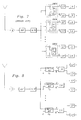
- FIG. 1 is a block diagram of a simple FIR filter
- FIG. 2 is a block diagram of an embodiment of a corresponding complex FIR filter
- FIG. 3 is a block diagram of another embodiment of a complex FIR filter
- FIG. 4 is a block diagram illustrating complex multiplication performed by the filters in FIGS. 2 and 3;
- FIG. 5 is a block diagram of a real bilinear digital ladder filter (BDLF filter).
- FIG. 6 is a block diagram of an embodiment of a complex BDLF filter in accordance with the present invention.
- FIG. 7 is a block diagram of a previously known base station that transforms a wideband high-frequency signal into separated baseband signals
- FIG. 8 is a block diagram of a preferred embodiment of a base station in accordance with the present invention that transforms a wideband high-frequency signal into separated baseband signals;
- FIG. 9 is a power spectrum diagram illustrating the operation of the base station in FIG. 7;
- FIG. 10 is a power spectrum diagram illustrating the operation of the base station in FIG. 8;
- FIG. 11 is a block diagram of a previously known base station that transforms a set of baseband signals into a wideband high-frequency signal
- FIG. 12 is a preferred embodiment of a base station in accordance with the present invention that transforms a set of baseband signals into a wideband high-frequency signal;
- FIG. 13 is a power spectrum diagram illustrating the operation of the base station in FIG. 11;
- FIG. 14 is a power spectrum diagram illustrating the operation of the base station in FIG. 12;
- FIG. 15 is a power spectrum diagram illustrating a baseband signal
- FIG. 16 is a power spectrum diagram illustrating the effect of setting some of the samples in a baseband signal having the power spectrum of FIG. 15 to zero;
- FIG. 17 is a power spectrum diagram illustrating the effect of omitting the zero samples in a signal having the power spectrum of FIG. 16;
- FIG. 18 is a power spectrum diagram illustrating a passband signal
- FIG. 19 is a power spectrum diagram illustrating the effect of setting some of the samples in a passband signal having the power spectrum of FIG. 18 to zero;
- FIG. 20 is a power spectrum diagram illustrating the effect of omitting the zero samples in a signal having the power spectrum of FIG. 19;
- FIG. 21 is a power spectrum diagram illustrating a wideband signal
- FIG. 22 is a power spectrum diagram illustrating a complex filter intended to operate on a wideband signal having the power spectrum of FIG. 21;
- FIG. 23 is a power spectrum diagram illustrating the effect of the complex filter on a wideband signal having the power spectrum of FIG. 21;
- FIG. 24 is a power spectrum diagram illustrating the effect of setting some of the samples in a passband signal having the power spectrum of FIG. 23 to zero;
- FIG. 25 is a power spectrum diagram illustrating the effect of omitting the zero samples in a signal having the power spectrum of FIG. 24;
- FIG. 26 is a power spectrum diagram illustrating a wideband signal
- FIG. 27 is a power spectrum diagram illustrating a complex filter intended to operate on a wideband signal having the power spectrum of FIG. 26;
- FIG. 28 is a power spectrum diagram illustrating the effect of the complex filter on a wideband signal having the power spectrum of FIG. 26;
- FIG. 29 is a power spectrum diagram illustrating the effect of setting some of the samples in a passband signal having the power spectrum of FIG. 28 to zero;
- FIG. 30 is a power spectrum diagram illustrating the effect of omitting the zero samples in a signal having the power spectrum of FIG. 29;
- FIG. 31 is a power spectrum diagram illustrating the effect of lowpass filtering a signal having the power spectrum of FIG. 30;
- FIG. 32 is a power spectrum diagram illustrating a baseband signal
- FIG. 33 is a power spectrum diagram illustrating the effect of zero filling a baseband signal having the power spectrum of FIG. 32;
- FIG. 34 is a power spectrum diagram illustrating the effect of lowpass filtering a signal having the power spectrum of FIG. 33;
- FIG. 35 is a power spectrum diagram illustrating a baseband signal
- FIG. 36 is a power spectrum diagram illustrating the effect of zero filling a baseband signal having the power spectrum of FIG. 35;
- FIG. 37 is a power spectrum diagram illustrating the effect of complex passband filtering a signal having the power spectrum of FIG. 36;
- FIG. 38 is a flow chart illustrating the method for transforming a wideband signal into a set of baseband signals in accordance with the present invention
- FIG. 39 is a flow chart illustrating the method for transforming a set of baseband signals into a wideband signal in accordance with the present invention.
- FIG. 40 is a block diagram of a more general sampling rate converter that converts sampling frequencies by rational ratios
- FIG. 41 is a block diagram of a modified embodiment of a base station in accordance with the present invention that transforms a wideband high-frequency signal into separated baseband signals;
- FIG. 42 is a modified embodiment of a base station in accordance with the present invention that transforms a set of baseband signals into a wideband high-frequency signal;
- FIG. 43 is a flow chart illustrating a modified method in accordance with the present invention for transforming a wideband signal into a set of baseband signals.
- FIG. 44 is a flow chart illustrating modified method-in accordance with the present invention for transforming a set of baseband signals into a wideband signal
- FIG. 1 illustrates a simple FIR filter having two delay elements denoted z ⁇ 1 and filter coefficients a 0 , a 1 , and a 2 .
- An essential component of the present invention is a complex bandpass filter.
- such a complex bandpass filter is designed by designing a low-pass filter prototype having all the desired properties, i.e. passband ripple, transmission band and cut off frequency, and by frequency translating this low-pass filter into a complex bandpass filter. This frequency translation is done by substituting z 0 .z for z in the low-pass filter prototype transfer function.
- z 0 is a point on the unit circle defined by
- ⁇ 0 is the center (angular) frequency of the passband of the translated complex filter and T is the sampling period.
- the corresponding complex bandpass filter may be of the form shown in FIG. 2 .
- a multiplication by a factor z 0 ⁇ 1 is associated with each delay element z ⁇ 1 .
- the signal paths have been provided with double arrow heads in order to emphasize that the signals may be complex valued.
- FIG. 3 shows an equivalent complex filter, in which the complex multiplication has been combined with the filter coefficients instead, thereby reducing the number of required multipliers.
- the transfer functions of the filters in FIGS. 2 and 3 are the same.
- FIG. 4 illustrates a possible implementation of a multiplication of a complex input signal A by a complex coefficient z 0 for obtaining a complex output signal B. As may be seen from FIG. 4 this is accomplished by splitting the signals A and B and the multiplication coefficient z 0 into their respective real and imaginary components and performing 4 real multiplications and 2 real additions.
- BDLF filters bilinear digital ladder filters
- WDF filters wave digital filters
- cascade coupled biquads with respect to coefficient quantization and signal quantization noise levels.
- FIG. 5 shows a block diagram of a real fifth order BDLF low-pass filter. In this figure the same designations have been used as in [1]. Of special interest here are the delay elements z ⁇ 1 .
- this low-pass filter may be transformed into a bandpass filter as the filters of FIGS. 2 and 3.
- a complex BDLF bandpass filter is illustrated in the block diagram of FIG. 6 . (By utilizing high pass filters or wideband low-pass filter prototypes it is also possible to design complex band stop filters by performing the frequency shift on these prototypes instead.) The reason complex BDLF filters are preferred is that they maintain the excellent properties of real BDLF filters mentioned above.
- FIG. 7 illustrates a typical base station in a radio communication system. To facilitate the description, only the blocks that are necessary to describe the difference between the prior art and the present invention are included in the figure.
- An antenna receives a wideband signal that is amplified in a amplifier A, passed through a bandpass filter BP and converted into a digital real wideband signal by an analog-to-digital converter A/D.
- the A/D conversion is performed directly on the RF signal, however, it is also possible to perform the A/D conversion on an IF signal by including one or more mixing stages between bandpass filter BP and the A/D converter.
- the digital wideband signal includes all the channels (in an FDMA system) or channel groups (in a TDMA system).
- a channel or channel group separation is performed by feeding the digital wideband signal to a set of demodulators DEM.
- These demodulators have respective demodulation frequencies ⁇ 1 , ⁇ 2 , . . . , ⁇ N , which correspond to the center frequencies of the frequency bands that are to be separated.
- the demodulator produces the inphase (I) and quadrature (Q) components of each frequency band.
- the I and Q components have to be low-pass filtered in filters LP.
- FIG. 8 illustrates a similar block diagram of a base station in accordance with the present invention.
- the received signal is amplified, bandpass filtered and converted to digital form as in the embodiment of FIG. 7 .
- the digital wideband signal is not forwarded to demodulators as in FIG. 7, but is instead forwarded to a set of complex bandpass filters CMPLX BP having center frequencies ⁇ 1 , ⁇ 2 , . . . , ⁇ N . Since the wideband signal is a real signal, the other input to these complex bandpass filters CMPLX BP will be 0 (in this description it is assumed that the upper input and output signals of a complex bandpass filter correspond to the real parts while the lower input and output signals correspond to the imaginary part).
- FIGS. 9 and 10 compare the signal processing of the previously known base station in FIG. 7 and the base station of the present invention in accordance with the embodiment of FIG. 8 .
- Both embodiments start with a digital wideband signal WB.
- This wideband signal contains a large number of frequency bands, each band containing a channel or channel group.
- P represents the power of the respective signals, while ⁇ represents (angular) frequency.
- Wideband signal WB is a high-frequency signal. This fact has been represented by a broken frequency axis.
- the demodulations bring the channels of the wideband signal down to baseband. This may be seen in the middle of FIG. 9 . Note that the entire signal has been transformed to the base band, and that different frequency bands of the wideband signal are centered on the base band, depending on the used demodulation frequencies ⁇ 1 , ⁇ 2 , . . . , ⁇ N .
- this signal is passed through a set complex bandpass filters CMPLX BP. This transforms the wideband signal WB into a set of complex high-frequency narrowband signals centered around center frequencies ⁇ 1 , ⁇ 2 , . . . , ⁇ N as illustrated in the middle of FIG. 10 .
- the low-pass filtering will remove the unwanted narrow frequency bands and the decimation will reduce the sampling rate.
- the result will be the separated baseband signals illustrated on the right in FIG. 9 .
- the complex narrowband high-frequency signals are decimated. Finally, these decimated signals are low-pass filtered for obtaining the separated complex baseband signals.
- FIGS. 7-10 described how a wideband signal is separated into channels or channel groups.
- FIGS. 11-14 describe the reverse process, namely how channels or channel groups may be combined into a wideband signal for transmission by a base station.
- FIG. 11 shows the prior art solution to this problem.
- the I and Q components which now are baseband signals, are interpolated in up-samplers ⁇ U and lowpass filters LP.
- This up-sampling may be performed by inserting a number of zero samples between every sample of I and Q. If the same frequency bands as before are assumed, 999 zeros will be inserted between every sample of I and Q.
- This up-sampling produces a sequence in which replicas of the original spectrum are produced.
- the interpolated sequence is then obtained by low-pass filtering these signals in low-pass filters LP. This removes the replicas of the spectrum that are obtained by the zero filling.
- the interpolated signals are then modulated in modulators MOD at modulation frequencies ⁇ 1 , ⁇ 2 , . .
- FIG. 12 illustrates a corresponding base station in accordance with the present invention.
- zero filling will introduce replicas of the spectra.
- This narrow spectrum is obtained by filtering the zero filled or up-sampled signals through complex bandpass filters CMPLX BP with center frequencies ⁇ 1 , ⁇ 2 , . . . , ⁇ N .
- FIGS. 13 and 14 illustrate these processes in signal spectrum form.
- the baseband signals are interpolated, modulated and bandpass filtered. This gives the narrowband high-frequency signals in the middle of the figure. These signals are combined into a wideband signal WB.
- the baseband signals are upsampled and bandpass filtered at the corresponding center frequencies ⁇ 1 , ⁇ 2 , . . . , ⁇ N . These steps are described in more detail with reference to FIGS. 32-37. Finally the high-frequency narrowband signals are combined into wideband signal WB.
- FIGS. 15-17 illustrate decimation of a baseband signal.
- the spectrum of the original signal is shown in FIG. 15.
- the effect of the “zeroing” is to produce uniformly spaced replicas of the original spectrum.
- the decimation is completed by omitting the zero samples.
- the resulting spectrum is shown in FIG. 17 .
- FIG. 18 illustrates the spectrum of a passband signal.
- replicas of this spectrum are produced by zero filling the original signal. If the sampling frequency fs and decimation factor M have been carefully selected, the spectrum of one of the replicas of the passband signal will fall into the baseband. This is illustrated by FIG. 19 .
- FIGS. 16 and 19 show that they are in fact identical. Thus, by omitting the zero samples a decimated baseband signal with lower sampling frequency will be obtained also in this case, as illustrated by FIG. 20 .
- a key feature in the conversion of a passband signal to baseband by decimation is that the passband signal falls on the “replica grid” produced by the “zeroing”. In such a case a replica of the passband signal spectrum will automatically be produced in the baseband. A higher decimation factor will produce a denser grid and therefor increase the number of possible passband positions.
- FIG. 21 illustrates the spectrum of the wideband signal from analog-to-digital converter A/D in FIG. 8 .
- all possible “replica grid” positions have been indicated.
- the operator of the radio communication system is allocated only a certain frequency band in this wideband signal.
- 3 channels or channel groups
- FIGS. 26-31 illustrate a way to reduce these requirements by widening the transition band.
- FIG. 26 illustrates a similar wideband signal as in FIG. 21 .
- FIG. 27 After complex bandpass filtering (FIG. 28 ), zeroing (FIG. 29) and omission of zeroes the spectrum looks as in FIG. 30 .
- the unwanted part of the spectrum may be eliminated by a lowpass filter (LP in FIG. 8) represented by the wide solid line in FIG. 30 .
- FIGS. 32-37 illustrate the interpolation or up-sampling process in more detail.
- FIG. 32 shows the spectrum of a baseband signal.
- the spectrum in FIG. 33 represents the spectrum of a signal obtained by zero filling the signal having the spectrum in FIG. 32 . In the example 6 zeroes have been inserted between every sample in the original signal. After lowpass filtering (indicated by the wide solid line in FIG. 33) the spectrum of the interpolated signal looks as in FIG. 34 .
- FIGS. 35-37 show the same original signal as FIG. 32 .
- FIG. 36 shows the same original signal as FIG. 32 .
- FIG. 36 shows the same original signal as FIG. 32 .
- one of the replicas is used for further processing. This has been indicated by the wide solid line in FIG. 36 .
- This line represents a complex bandpass filter instead of a lowpass filter (in fact it represents the same lowpass filter transformed to a higher frequency as explained above with reference to FIGS. 1 and 2 ), which produces the desired high frequency signal (FIG. 36)
- the desired frequency band has to lie on the “replica grid”.
- FIG. 38 is a flow chart illustrating the essential steps in the channel or channel group separation method in accordance with the present invention.
- FIG. 39 is a flow chart illustrating the essential steps in the channel or channel group combination method in accordance with the present invention.
- FIG. 40 illustrates a generalization of the decimation and interpolation methods described above.
- the resampling of the signal is performed by a rational factor U/D. This is done by an up-sampling by a factor U, followed by bandpass filtering and down-sampling by a factor D. In this way it may be easier to adapt the channels to the “replica grid”.
- the preferred embodiment of the present invention relies on the feature that channels lie on, or may be transformed to (by rational resampling), the proper “replica grid”.
- some of the channels may not lie on or be resampled to such a grid, which means that these channels may not be directly decimated down to baseband or interpolated up to passband.
- most of the advantage obtained by the present invention may still be gained by performing a demodulation after decimation or a modulation before interpolation for these channels. These extra steps move these channels to frequencies on the grid, but do so at a low demodulation/modulation frequency instead of a high frequency as in the prior art. This still significantly reduces complexity.
- FIG. 41 is a block diagram of a modified embodiment of a base station in accordance with the present invention that transforms a wideband high-frequency signal into separated baseband signals.
- the difference between this modified version and the preferred embodiment of FIG. 8 is that low frequency demodulators DEM, defined by demodulation frequencies ⁇ 1 , ⁇ 2 , . . . , ⁇ N , have been provided after decimators ⁇ D to down-convert the channels that did not quite reach baseband by the decimation. Since this may apply only to some of the channels, the demodolators DEM are surrounded by a dashed line (they are only included if actually needed).
- FIG. 42 is a modified embodiment of a base station in accordance with the present invention that transforms a set of baseband signals into a wideband high-frequency signal.
- the difference between this modified version and the preferred embodiment of FIG. 12 is that low frequency modulators MOD, defined by modulation frequencies ⁇ 1 , ⁇ 2 , . . . , ⁇ N , have been provided before interpolators ⁇ U to up-convert the channels that would not quite reach the passband by the interpolation. Since this may apply only to some of the channels, the modulators MOD are surrounded by a dashed line (they are only included if actually needed).
- FIG. 43 is a flow chart illustrating the modified method for transforming a wideband signal into a set of baseband signals in accordance with the present invention.
- the difference with respect to the flow chart in FIG. 38 is the extra demodulation step after the down-sampling step.
- FIG. 44 is a flow chart illustrating the modified method for transforming a set of baseband signals into a wideband signal in accordance with the present invention.
- the difference with respect to the flow chart in FIG. 39 is the extra modulation step before the up-sampling step.
- complex bandpass filters that are used in the base station of the present invention preferably comprise complex BDLF filters, but it should be understood that other complex filter structures, such as FIR filters, WDF filters, biquads, etc may also be used.
Abstract
Description
Claims (9)
Priority Applications (1)
| Application Number | Priority Date | Filing Date | Title |
|---|---|---|---|
| US09/775,820 US6546061B2 (en) | 1996-10-02 | 2001-02-05 | Signal transformation method and apparatus |
Applications Claiming Priority (5)
| Application Number | Priority Date | Filing Date | Title |
|---|---|---|---|
| SE9603602A SE519541C2 (en) | 1996-10-02 | 1996-10-02 | Method and apparatus for transforming a real digital broadband bandpass signal into a set of digital baseband signals with I and Q components |
| SE9603602 | 1996-10-02 | ||
| SE9603602-5 | 1996-10-02 | ||
| US08/941,348 US6215828B1 (en) | 1996-02-10 | 1997-09-30 | Signal transformation method and apparatus |
| US09/775,820 US6546061B2 (en) | 1996-10-02 | 2001-02-05 | Signal transformation method and apparatus |
Related Parent Applications (1)
| Application Number | Title | Priority Date | Filing Date |
|---|---|---|---|
| US08/941,348 Division US6215828B1 (en) | 1996-02-10 | 1997-09-30 | Signal transformation method and apparatus |
Publications (2)
| Publication Number | Publication Date |
|---|---|
| US20010050966A1 US20010050966A1 (en) | 2001-12-13 |
| US6546061B2 true US6546061B2 (en) | 2003-04-08 |
Family
ID=26662765
Family Applications (1)
| Application Number | Title | Priority Date | Filing Date |
|---|---|---|---|
| US09/775,820 Expired - Lifetime US6546061B2 (en) | 1996-10-02 | 2001-02-05 | Signal transformation method and apparatus |
Country Status (1)
| Country | Link |
|---|---|
| US (1) | US6546061B2 (en) |
Cited By (22)
| Publication number | Priority date | Publication date | Assignee | Title |
|---|---|---|---|---|
| US20050143042A1 (en) * | 1999-04-16 | 2005-06-30 | Parkervision, Inc. | DC offset, re-radiation, and I/Q solutions using universal frequency translation technology |
| US6930565B1 (en) * | 2003-04-28 | 2005-08-16 | Adam S. Vishinsky | Fully integrated automatically-tuned RF and IF active bandpass filters |
| US20060014501A1 (en) * | 1998-10-21 | 2006-01-19 | Parkervision, Inc. | Applications of universal frequency translation |
| US20060159013A1 (en) * | 2005-01-14 | 2006-07-20 | Lee Jung A | Method of controlling transmission rates |
| US20070041435A1 (en) * | 2002-07-18 | 2007-02-22 | Parkervision, Inc. | Networking methods and systems |
| US20070105510A1 (en) * | 1998-10-21 | 2007-05-10 | Parkervision, Inc. | Apparatus and method for communicating an input signal in polar representation |
| US20070293182A1 (en) * | 2000-04-14 | 2007-12-20 | Parkervision, Inc. | Apparatus, system, and method for down converting and up converting electromagnetic signals |
| US20080272441A1 (en) * | 1998-10-21 | 2008-11-06 | Parkervision, Inc. | Method and circuit for down-converting a signal |
| US7653145B2 (en) | 1999-08-04 | 2010-01-26 | Parkervision, Inc. | Wireless local area network (WLAN) using universal frequency translation technology including multi-phase embodiments and circuit implementations |
| US7653158B2 (en) | 2001-11-09 | 2010-01-26 | Parkervision, Inc. | Gain control in a communication channel |
| US7693230B2 (en) * | 1999-04-16 | 2010-04-06 | Parkervision, Inc. | Apparatus and method of differential IQ frequency up-conversion |
| US7724845B2 (en) | 1999-04-16 | 2010-05-25 | Parkervision, Inc. | Method and system for down-converting and electromagnetic signal, and transforms for same |
| US7773688B2 (en) | 1999-04-16 | 2010-08-10 | Parkervision, Inc. | Method, system, and apparatus for balanced frequency up-conversion, including circuitry to directly couple the outputs of multiple transistors |
| US7865177B2 (en) | 1998-10-21 | 2011-01-04 | Parkervision, Inc. | Method and system for down-converting an electromagnetic signal, and transforms for same, and aperture relationships |
| US20110053512A1 (en) * | 2004-12-07 | 2011-03-03 | Atc Technologies, Llc | Broadband wireless communications systems and methods using multiple non-contiguous frequency bands/segments |
| US7991815B2 (en) | 2000-11-14 | 2011-08-02 | Parkervision, Inc. | Methods, systems, and computer program products for parallel correlation and applications thereof |
| US8019291B2 (en) | 1998-10-21 | 2011-09-13 | Parkervision, Inc. | Method and system for frequency down-conversion and frequency up-conversion |
| US8233855B2 (en) | 1998-10-21 | 2012-07-31 | Parkervision, Inc. | Up-conversion based on gated information signal |
| US8295406B1 (en) | 1999-08-04 | 2012-10-23 | Parkervision, Inc. | Universal platform module for a plurality of communication protocols |
| US8407061B2 (en) | 2002-07-18 | 2013-03-26 | Parkervision, Inc. | Networking methods and systems |
| CN110389362A (en) * | 2018-04-23 | 2019-10-29 | 三星电子株式会社 | Global navigational satellite system receiver and its method |
| US11303326B2 (en) * | 2018-03-08 | 2022-04-12 | Telefonaktiebolaget Lm Ericsson (Publ) | Method and apparatus for handling antenna signals for transmission between a base unit and a remote unit of a base station system |
Families Citing this family (6)
| Publication number | Priority date | Publication date | Assignee | Title |
|---|---|---|---|---|
| EP1620955A1 (en) * | 2002-11-18 | 2006-02-01 | Koninklijke Philips Electronics N.V. | Automatic gain control using signal and interference power to obtain extended blocking performance |
| US7486338B1 (en) * | 2003-04-28 | 2009-02-03 | Wyszynski Adam S | Fully integrated terrestrial TV tuner architecture |
| US7428281B2 (en) * | 2004-08-31 | 2008-09-23 | Texas Instruments Incorporated | System and method of removing discrete spurious signals in cable broadband and other RF environments |
| WO2007013036A2 (en) * | 2005-07-29 | 2007-02-01 | Nxp B.V. | Digital filter |
| KR100963513B1 (en) * | 2006-12-04 | 2010-06-15 | 삼성전자주식회사 | Apparatus and method for frame structure in wide-band wireless communication systems |
| KR101510454B1 (en) | 2010-09-20 | 2015-04-15 | 한국전자통신연구원 | Bandpass sampling receiver and filter design and reconfiguration method thereof |
Citations (5)
| Publication number | Priority date | Publication date | Assignee | Title |
|---|---|---|---|---|
| US3804988A (en) | 1972-07-14 | 1974-04-16 | Carrier Tel Corp America Inc | Carrier system for efficient connection of telephone subscribers to central office |
| US4891840A (en) | 1986-03-10 | 1990-01-02 | American Telephone And Telegraph Company, At&T Bell Laboratories | Multi-channel signal transmission |
| US5388062A (en) | 1993-05-06 | 1995-02-07 | Thomson Consumer Electronics, Inc. | Reconfigurable programmable digital filter architecture useful in communication receiver |
| US5473280A (en) * | 1993-02-18 | 1995-12-05 | Hitachi, Ltd. | Modulation/demodulation method and system for realizing quadrature modulation/demodulation technique used in digital mobile radio system with complex signal processing |
| US5579341A (en) | 1994-12-29 | 1996-11-26 | Motorola, Inc. | Multi-channel digital transceiver and method |
-
2001
- 2001-02-05 US US09/775,820 patent/US6546061B2/en not_active Expired - Lifetime
Patent Citations (5)
| Publication number | Priority date | Publication date | Assignee | Title |
|---|---|---|---|---|
| US3804988A (en) | 1972-07-14 | 1974-04-16 | Carrier Tel Corp America Inc | Carrier system for efficient connection of telephone subscribers to central office |
| US4891840A (en) | 1986-03-10 | 1990-01-02 | American Telephone And Telegraph Company, At&T Bell Laboratories | Multi-channel signal transmission |
| US5473280A (en) * | 1993-02-18 | 1995-12-05 | Hitachi, Ltd. | Modulation/demodulation method and system for realizing quadrature modulation/demodulation technique used in digital mobile radio system with complex signal processing |
| US5388062A (en) | 1993-05-06 | 1995-02-07 | Thomson Consumer Electronics, Inc. | Reconfigurable programmable digital filter architecture useful in communication receiver |
| US5579341A (en) | 1994-12-29 | 1996-11-26 | Motorola, Inc. | Multi-channel digital transceiver and method |
Non-Patent Citations (2)
| Title |
|---|
| Proakis, John G. et al., "Digital Signal Processing:Principles, Algorithms, and Applications", Chapter 6.2.1 and 7.2.4, (1992). |
| Signell, S. et al., "Design and Analysis of Bilinear Digital Ladder Filters", IEEE Transactions of Circuits and Systems, pp. 1-13, (Feb. 1996). |
Cited By (46)
| Publication number | Priority date | Publication date | Assignee | Title |
|---|---|---|---|---|
| US7936022B2 (en) | 1998-10-21 | 2011-05-03 | Parkervision, Inc. | Method and circuit for down-converting a signal |
| US7826817B2 (en) | 1998-10-21 | 2010-11-02 | Parker Vision, Inc. | Applications of universal frequency translation |
| US20060014501A1 (en) * | 1998-10-21 | 2006-01-19 | Parkervision, Inc. | Applications of universal frequency translation |
| US8340618B2 (en) | 1998-10-21 | 2012-12-25 | Parkervision, Inc. | Method and system for down-converting an electromagnetic signal, and transforms for same, and aperture relationships |
| US8233855B2 (en) | 1998-10-21 | 2012-07-31 | Parkervision, Inc. | Up-conversion based on gated information signal |
| US20070105510A1 (en) * | 1998-10-21 | 2007-05-10 | Parkervision, Inc. | Apparatus and method for communicating an input signal in polar representation |
| US8190116B2 (en) | 1998-10-21 | 2012-05-29 | Parker Vision, Inc. | Methods and systems for down-converting a signal using a complementary transistor structure |
| US20080272441A1 (en) * | 1998-10-21 | 2008-11-06 | Parkervision, Inc. | Method and circuit for down-converting a signal |
| US20090203345A1 (en) * | 1998-10-21 | 2009-08-13 | Parkervision, Inc. | Method and system for down-converting an Electromagnetic signal, transforms for same, and Aperture relationships |
| US8190108B2 (en) | 1998-10-21 | 2012-05-29 | Parkervision, Inc. | Method and system for frequency up-conversion |
| US8160534B2 (en) | 1998-10-21 | 2012-04-17 | Parkervision, Inc. | Applications of universal frequency translation |
| US7693502B2 (en) | 1998-10-21 | 2010-04-06 | Parkervision, Inc. | Method and system for down-converting an electromagnetic signal, transforms for same, and aperture relationships |
| US8019291B2 (en) | 1998-10-21 | 2011-09-13 | Parkervision, Inc. | Method and system for frequency down-conversion and frequency up-conversion |
| US7697916B2 (en) | 1998-10-21 | 2010-04-13 | Parkervision, Inc. | Applications of universal frequency translation |
| US7865177B2 (en) | 1998-10-21 | 2011-01-04 | Parkervision, Inc. | Method and system for down-converting an electromagnetic signal, and transforms for same, and aperture relationships |
| US7693230B2 (en) * | 1999-04-16 | 2010-04-06 | Parkervision, Inc. | Apparatus and method of differential IQ frequency up-conversion |
| US20050143042A1 (en) * | 1999-04-16 | 2005-06-30 | Parkervision, Inc. | DC offset, re-radiation, and I/Q solutions using universal frequency translation technology |
| US7773688B2 (en) | 1999-04-16 | 2010-08-10 | Parkervision, Inc. | Method, system, and apparatus for balanced frequency up-conversion, including circuitry to directly couple the outputs of multiple transistors |
| US7724845B2 (en) | 1999-04-16 | 2010-05-25 | Parkervision, Inc. | Method and system for down-converting and electromagnetic signal, and transforms for same |
| US7894789B2 (en) | 1999-04-16 | 2011-02-22 | Parkervision, Inc. | Down-conversion of an electromagnetic signal with feedback control |
| US8594228B2 (en) | 1999-04-16 | 2013-11-26 | Parkervision, Inc. | Apparatus and method of differential IQ frequency up-conversion |
| US7929638B2 (en) | 1999-04-16 | 2011-04-19 | Parkervision, Inc. | Wireless local area network (WLAN) using universal frequency translation technology including multi-phase embodiments |
| US8224281B2 (en) | 1999-04-16 | 2012-07-17 | Parkervision, Inc. | Down-conversion of an electromagnetic signal with feedback control |
| US8077797B2 (en) | 1999-04-16 | 2011-12-13 | Parkervision, Inc. | Method, system, and apparatus for balanced frequency up-conversion of a baseband signal |
| US8229023B2 (en) | 1999-04-16 | 2012-07-24 | Parkervision, Inc. | Wireless local area network (WLAN) using universal frequency translation technology including multi-phase embodiments |
| US8223898B2 (en) | 1999-04-16 | 2012-07-17 | Parkervision, Inc. | Method and system for down-converting an electromagnetic signal, and transforms for same |
| US8036304B2 (en) | 1999-04-16 | 2011-10-11 | Parkervision, Inc. | Apparatus and method of differential IQ frequency up-conversion |
| US8295406B1 (en) | 1999-08-04 | 2012-10-23 | Parkervision, Inc. | Universal platform module for a plurality of communication protocols |
| US7653145B2 (en) | 1999-08-04 | 2010-01-26 | Parkervision, Inc. | Wireless local area network (WLAN) using universal frequency translation technology including multi-phase embodiments and circuit implementations |
| US8295800B2 (en) | 2000-04-14 | 2012-10-23 | Parkervision, Inc. | Apparatus and method for down-converting electromagnetic signals by controlled charging and discharging of a capacitor |
| US7822401B2 (en) | 2000-04-14 | 2010-10-26 | Parkervision, Inc. | Apparatus and method for down-converting electromagnetic signals by controlled charging and discharging of a capacitor |
| US20070293182A1 (en) * | 2000-04-14 | 2007-12-20 | Parkervision, Inc. | Apparatus, system, and method for down converting and up converting electromagnetic signals |
| US7991815B2 (en) | 2000-11-14 | 2011-08-02 | Parkervision, Inc. | Methods, systems, and computer program products for parallel correlation and applications thereof |
| US8446994B2 (en) | 2001-11-09 | 2013-05-21 | Parkervision, Inc. | Gain control in a communication channel |
| US7653158B2 (en) | 2001-11-09 | 2010-01-26 | Parkervision, Inc. | Gain control in a communication channel |
| US20070041435A1 (en) * | 2002-07-18 | 2007-02-22 | Parkervision, Inc. | Networking methods and systems |
| US8407061B2 (en) | 2002-07-18 | 2013-03-26 | Parkervision, Inc. | Networking methods and systems |
| US6930565B1 (en) * | 2003-04-28 | 2005-08-16 | Adam S. Vishinsky | Fully integrated automatically-tuned RF and IF active bandpass filters |
| US8285225B2 (en) * | 2004-12-07 | 2012-10-09 | Atc Technologies, Llc | Broadband wireless communications systems and methods using multiple non-contiguous frequency bands/segments |
| US20110053512A1 (en) * | 2004-12-07 | 2011-03-03 | Atc Technologies, Llc | Broadband wireless communications systems and methods using multiple non-contiguous frequency bands/segments |
| US20060159013A1 (en) * | 2005-01-14 | 2006-07-20 | Lee Jung A | Method of controlling transmission rates |
| US7995585B2 (en) * | 2005-01-14 | 2011-08-09 | Alcatel Lucent | Method of controlling transmission rates |
| US11303326B2 (en) * | 2018-03-08 | 2022-04-12 | Telefonaktiebolaget Lm Ericsson (Publ) | Method and apparatus for handling antenna signals for transmission between a base unit and a remote unit of a base station system |
| CN110389362A (en) * | 2018-04-23 | 2019-10-29 | 三星电子株式会社 | Global navigational satellite system receiver and its method |
| KR20190123196A (en) * | 2018-04-23 | 2019-10-31 | 삼성전자주식회사 | Asymmetrical filtering to improve GNSS performance in presence of wideband interference |
| US11463071B2 (en) * | 2018-04-23 | 2022-10-04 | Samsung Electronics Co,. Ltd | Asymmetrical filtering to improve GNSS performance in presence of wideband interference |
Also Published As
| Publication number | Publication date |
|---|---|
| US20010050966A1 (en) | 2001-12-13 |
Similar Documents
| Publication | Publication Date | Title |
|---|---|---|
| US6215828B1 (en) | Signal transformation method and apparatus | |
| US6546061B2 (en) | Signal transformation method and apparatus | |
| US6611569B1 (en) | Down/up-conversion apparatus and method | |
| Hentschel et al. | Sample rate conversion for software radio | |
| AU606007B2 (en) | Efficient digital frequency division multiplexed signal receiver | |
| US4803700A (en) | Method of, and demodulator for, digitally demodulating an SSB signal | |
| US5222144A (en) | Digital quadrature radio receiver with two-step processing | |
| US5930301A (en) | Up-conversion mechanism employing side lobe-selective pre-distortion filter and frequency replica-selecting bandpass filter respectively installed upstream and downstream of digital-to-analog converter | |
| US9106492B2 (en) | Digital receiver | |
| CA2315940C (en) | Decimation filtering apparatus and method | |
| US4974236A (en) | Arrangement for generating an SSB signal | |
| US5757867A (en) | Digital mixing to baseband decimation filter | |
| US4896152A (en) | Telemetry system with a sending station using recursive filter for bandwidth limiting | |
| US7035888B2 (en) | Digital sampling rate converter for compensation for drop of in-band signal | |
| RU2292658C2 (en) | Digital mutli-frequency transmitter | |
| EP0944978A1 (en) | A method and system for quadrature modulation and digital-to-analog conversion | |
| US7450660B2 (en) | Apparatus and method for digital modulation | |
| Scholnik et al. | Integrated IQ demodulation, matched filtering, and symbol-rate sampling using minimum-rate IF sampling | |
| KR0156195B1 (en) | An apparatus for transmitting and receiving digital data | |
| JP2901427B2 (en) | FM demodulator | |
| Harris | A Fresh View of Digital Signal Processing for Software Defined Radios: Part II | |
| WO2003069772A2 (en) | Digital modulator |
Legal Events
| Date | Code | Title | Description |
|---|---|---|---|
| STCF | Information on status: patent grant |
Free format text: PATENTED CASE |
|
| FPAY | Fee payment |
Year of fee payment: 4 |
|
| FPAY | Fee payment |
Year of fee payment: 8 |
|
| AS | Assignment |
Owner name: TELEFONAKTIEBOLAGET L M ERICSSON, SWEDEN Free format text: ASSIGNMENT OF ASSIGNORS INTEREST;ASSIGNORS:SIGNELL, SVANTE;SCHIER, THORSTEN;REEL/FRAME:030267/0263 Effective date: 19970905 |
|
| AS | Assignment |
Owner name: CLUSTER LLC, DELAWARE Free format text: ASSIGNMENT OF ASSIGNORS INTEREST;ASSIGNOR:TELEFONAKTIEBOLAGET L M ERICSSON (PUBL);REEL/FRAME:030281/0256 Effective date: 20130211 |
|
| AS | Assignment |
Owner name: UNWIRED PLANET, LLC, NEVADA Free format text: ASSIGNMENT OF ASSIGNORS INTEREST;ASSIGNOR:CLUSTER LLC;REEL/FRAME:030292/0532 Effective date: 20130213 |
|
| AS | Assignment |
Owner name: CLUSTER LLC, SWEDEN Free format text: NOTICE OF GRANT OF SECURITY INTEREST IN PATENTS;ASSIGNOR:UNWIRED PLANET, LLC;REEL/FRAME:030369/0601 Effective date: 20130213 |
|
| FEPP | Fee payment procedure |
Free format text: PAYOR NUMBER ASSIGNED (ORIGINAL EVENT CODE: ASPN); ENTITY STATUS OF PATENT OWNER: LARGE ENTITY Free format text: PAYER NUMBER DE-ASSIGNED (ORIGINAL EVENT CODE: RMPN); ENTITY STATUS OF PATENT OWNER: LARGE ENTITY |
|
| FPAY | Fee payment |
Year of fee payment: 12 |