EP4471485A2 - Multiaperturkameras mit mindestens einer zweizustands-zoomkamera - Google Patents
Multiaperturkameras mit mindestens einer zweizustands-zoomkamera Download PDFInfo
- Publication number
- EP4471485A2 EP4471485A2 EP24207348.4A EP24207348A EP4471485A2 EP 4471485 A2 EP4471485 A2 EP 4471485A2 EP 24207348 A EP24207348 A EP 24207348A EP 4471485 A2 EP4471485 A2 EP 4471485A2
- Authority
- EP
- European Patent Office
- Prior art keywords
- lens
- efl
- camera module
- camera
- zoom
- Prior art date
- Legal status (The legal status is an assumption and is not a legal conclusion. Google has not performed a legal analysis and makes no representation as to the accuracy of the status listed.)
- Pending
Links
- 230000003287 optical effect Effects 0.000 claims abstract description 102
- 230000007246 mechanism Effects 0.000 claims description 6
- 230000009977 dual effect Effects 0.000 claims 1
- 238000013461 design Methods 0.000 description 60
- 230000008859 change Effects 0.000 description 17
- 238000000429 assembly Methods 0.000 description 14
- 238000000034 method Methods 0.000 description 14
- 239000011521 glass Substances 0.000 description 12
- 230000005291 magnetic effect Effects 0.000 description 11
- 230000008569 process Effects 0.000 description 8
- 239000000463 material Substances 0.000 description 5
- 230000003068 static effect Effects 0.000 description 4
- 230000000694 effects Effects 0.000 description 3
- 230000005294 ferromagnetic effect Effects 0.000 description 3
- 239000000758 substrate Substances 0.000 description 3
- 230000002596 correlated effect Effects 0.000 description 2
- 239000003302 ferromagnetic material Substances 0.000 description 2
- 238000010137 moulding (plastic) Methods 0.000 description 2
- 230000006641 stabilisation Effects 0.000 description 2
- 238000011105 stabilization Methods 0.000 description 2
- 238000004804 winding Methods 0.000 description 2
- 238000004026 adhesive bonding Methods 0.000 description 1
- 230000000712 assembly Effects 0.000 description 1
- 229910010293 ceramic material Inorganic materials 0.000 description 1
- 230000008878 coupling Effects 0.000 description 1
- 238000010168 coupling process Methods 0.000 description 1
- 238000005859 coupling reaction Methods 0.000 description 1
- 230000001419 dependent effect Effects 0.000 description 1
- 238000010586 diagram Methods 0.000 description 1
- 239000000428 dust Substances 0.000 description 1
- 238000005516 engineering process Methods 0.000 description 1
- 238000001914 filtration Methods 0.000 description 1
- 230000006870 function Effects 0.000 description 1
- 238000003384 imaging method Methods 0.000 description 1
- 238000010348 incorporation Methods 0.000 description 1
- 230000013011 mating Effects 0.000 description 1
- 229910052751 metal Inorganic materials 0.000 description 1
- 239000002184 metal Substances 0.000 description 1
- 238000012986 modification Methods 0.000 description 1
- 230000004048 modification Effects 0.000 description 1
- TWNQGVIAIRXVLR-UHFFFAOYSA-N oxo(oxoalumanyloxy)alumane Chemical compound O=[Al]O[Al]=O TWNQGVIAIRXVLR-UHFFFAOYSA-N 0.000 description 1
- 238000012545 processing Methods 0.000 description 1
- 238000012546 transfer Methods 0.000 description 1
Images


Classifications
-
- H—ELECTRICITY
- H04—ELECTRIC COMMUNICATION TECHNIQUE
- H04N—PICTORIAL COMMUNICATION, e.g. TELEVISION
- H04N23/00—Cameras or camera modules comprising electronic image sensors; Control thereof
- H04N23/90—Arrangement of cameras or camera modules, e.g. multiple cameras in TV studios or sports stadiums
-
- G—PHYSICS
- G02—OPTICS
- G02B—OPTICAL ELEMENTS, SYSTEMS OR APPARATUS
- G02B13/00—Optical objectives specially designed for the purposes specified below
- G02B13/001—Miniaturised objectives for electronic devices, e.g. portable telephones, webcams, PDAs, small digital cameras
- G02B13/0055—Miniaturised objectives for electronic devices, e.g. portable telephones, webcams, PDAs, small digital cameras employing a special optical element
- G02B13/0065—Miniaturised objectives for electronic devices, e.g. portable telephones, webcams, PDAs, small digital cameras employing a special optical element having a beam-folding prism or mirror
-
- G—PHYSICS
- G02—OPTICS
- G02B—OPTICAL ELEMENTS, SYSTEMS OR APPARATUS
- G02B13/00—Optical objectives specially designed for the purposes specified below
- G02B13/001—Miniaturised objectives for electronic devices, e.g. portable telephones, webcams, PDAs, small digital cameras
- G02B13/009—Miniaturised objectives for electronic devices, e.g. portable telephones, webcams, PDAs, small digital cameras having zoom function
-
- G—PHYSICS
- G02—OPTICS
- G02B—OPTICAL ELEMENTS, SYSTEMS OR APPARATUS
- G02B13/00—Optical objectives specially designed for the purposes specified below
- G02B13/02—Telephoto objectives, i.e. systems of the type + - in which the distance from the front vertex to the image plane is less than the equivalent focal length
-
- G—PHYSICS
- G02—OPTICS
- G02B—OPTICAL ELEMENTS, SYSTEMS OR APPARATUS
- G02B15/00—Optical objectives with means for varying the magnification
- G02B15/14—Optical objectives with means for varying the magnification by axial movement of one or more lenses or groups of lenses relative to the image plane for continuously varying the equivalent focal length of the objective
- G02B15/143—Optical objectives with means for varying the magnification by axial movement of one or more lenses or groups of lenses relative to the image plane for continuously varying the equivalent focal length of the objective having three groups only
- G02B15/1431—Optical objectives with means for varying the magnification by axial movement of one or more lenses or groups of lenses relative to the image plane for continuously varying the equivalent focal length of the objective having three groups only the first group being positive
- G02B15/143103—Optical objectives with means for varying the magnification by axial movement of one or more lenses or groups of lenses relative to the image plane for continuously varying the equivalent focal length of the objective having three groups only the first group being positive arranged ++-
-
- G—PHYSICS
- G03—PHOTOGRAPHY; CINEMATOGRAPHY; ANALOGOUS TECHNIQUES USING WAVES OTHER THAN OPTICAL WAVES; ELECTROGRAPHY; HOLOGRAPHY
- G03B—APPARATUS OR ARRANGEMENTS FOR TAKING PHOTOGRAPHS OR FOR PROJECTING OR VIEWING THEM; APPARATUS OR ARRANGEMENTS EMPLOYING ANALOGOUS TECHNIQUES USING WAVES OTHER THAN OPTICAL WAVES; ACCESSORIES THEREFOR
- G03B17/00—Details of cameras or camera bodies; Accessories therefor
- G03B17/02—Bodies
- G03B17/12—Bodies with means for supporting objectives, supplementary lenses, filters, masks, or turrets
-
- G—PHYSICS
- G03—PHOTOGRAPHY; CINEMATOGRAPHY; ANALOGOUS TECHNIQUES USING WAVES OTHER THAN OPTICAL WAVES; ELECTROGRAPHY; HOLOGRAPHY
- G03B—APPARATUS OR ARRANGEMENTS FOR TAKING PHOTOGRAPHS OR FOR PROJECTING OR VIEWING THEM; APPARATUS OR ARRANGEMENTS EMPLOYING ANALOGOUS TECHNIQUES USING WAVES OTHER THAN OPTICAL WAVES; ACCESSORIES THEREFOR
- G03B17/00—Details of cameras or camera bodies; Accessories therefor
- G03B17/02—Bodies
- G03B17/17—Bodies with reflectors arranged in beam forming the photographic image, e.g. for reducing dimensions of camera
-
- G—PHYSICS
- G03—PHOTOGRAPHY; CINEMATOGRAPHY; ANALOGOUS TECHNIQUES USING WAVES OTHER THAN OPTICAL WAVES; ELECTROGRAPHY; HOLOGRAPHY
- G03B—APPARATUS OR ARRANGEMENTS FOR TAKING PHOTOGRAPHS OR FOR PROJECTING OR VIEWING THEM; APPARATUS OR ARRANGEMENTS EMPLOYING ANALOGOUS TECHNIQUES USING WAVES OTHER THAN OPTICAL WAVES; ACCESSORIES THEREFOR
- G03B19/00—Cameras
- G03B19/18—Motion-picture cameras
- G03B19/22—Double cameras
-
- G—PHYSICS
- G03—PHOTOGRAPHY; CINEMATOGRAPHY; ANALOGOUS TECHNIQUES USING WAVES OTHER THAN OPTICAL WAVES; ELECTROGRAPHY; HOLOGRAPHY
- G03B—APPARATUS OR ARRANGEMENTS FOR TAKING PHOTOGRAPHS OR FOR PROJECTING OR VIEWING THEM; APPARATUS OR ARRANGEMENTS EMPLOYING ANALOGOUS TECHNIQUES USING WAVES OTHER THAN OPTICAL WAVES; ACCESSORIES THEREFOR
- G03B3/00—Focusing arrangements of general interest for cameras, projectors or printers
- G03B3/10—Power-operated focusing
-
- G—PHYSICS
- G03—PHOTOGRAPHY; CINEMATOGRAPHY; ANALOGOUS TECHNIQUES USING WAVES OTHER THAN OPTICAL WAVES; ELECTROGRAPHY; HOLOGRAPHY
- G03B—APPARATUS OR ARRANGEMENTS FOR TAKING PHOTOGRAPHS OR FOR PROJECTING OR VIEWING THEM; APPARATUS OR ARRANGEMENTS EMPLOYING ANALOGOUS TECHNIQUES USING WAVES OTHER THAN OPTICAL WAVES; ACCESSORIES THEREFOR
- G03B30/00—Camera modules comprising integrated lens units and imaging units, specially adapted for being embedded in other devices, e.g. mobile phones or vehicles
-
- G—PHYSICS
- G03—PHOTOGRAPHY; CINEMATOGRAPHY; ANALOGOUS TECHNIQUES USING WAVES OTHER THAN OPTICAL WAVES; ELECTROGRAPHY; HOLOGRAPHY
- G03B—APPARATUS OR ARRANGEMENTS FOR TAKING PHOTOGRAPHS OR FOR PROJECTING OR VIEWING THEM; APPARATUS OR ARRANGEMENTS EMPLOYING ANALOGOUS TECHNIQUES USING WAVES OTHER THAN OPTICAL WAVES; ACCESSORIES THEREFOR
- G03B5/00—Adjustment of optical system relative to image or object surface other than for focusing
-
- H—ELECTRICITY
- H04—ELECTRIC COMMUNICATION TECHNIQUE
- H04N—PICTORIAL COMMUNICATION, e.g. TELEVISION
- H04N23/00—Cameras or camera modules comprising electronic image sensors; Control thereof
- H04N23/45—Cameras or camera modules comprising electronic image sensors; Control thereof for generating image signals from two or more image sensors being of different type or operating in different modes, e.g. with a CMOS sensor for moving images in combination with a charge-coupled device [CCD] for still images
-
- H—ELECTRICITY
- H04—ELECTRIC COMMUNICATION TECHNIQUE
- H04N—PICTORIAL COMMUNICATION, e.g. TELEVISION
- H04N23/00—Cameras or camera modules comprising electronic image sensors; Control thereof
- H04N23/57—Mechanical or electrical details of cameras or camera modules specially adapted for being embedded in other devices
-
- H—ELECTRICITY
- H04—ELECTRIC COMMUNICATION TECHNIQUE
- H04N—PICTORIAL COMMUNICATION, e.g. TELEVISION
- H04N23/00—Cameras or camera modules comprising electronic image sensors; Control thereof
- H04N23/60—Control of cameras or camera modules
- H04N23/665—Control of cameras or camera modules involving internal camera communication with the image sensor, e.g. synchronising or multiplexing SSIS control signals
-
- H—ELECTRICITY
- H04—ELECTRIC COMMUNICATION TECHNIQUE
- H04N—PICTORIAL COMMUNICATION, e.g. TELEVISION
- H04N23/00—Cameras or camera modules comprising electronic image sensors; Control thereof
- H04N23/60—Control of cameras or camera modules
- H04N23/67—Focus control based on electronic image sensor signals
-
- H—ELECTRICITY
- H04—ELECTRIC COMMUNICATION TECHNIQUE
- H04N—PICTORIAL COMMUNICATION, e.g. TELEVISION
- H04N23/00—Cameras or camera modules comprising electronic image sensors; Control thereof
- H04N23/60—Control of cameras or camera modules
- H04N23/68—Control of cameras or camera modules for stable pick-up of the scene, e.g. compensating for camera body vibrations
- H04N23/682—Vibration or motion blur correction
- H04N23/685—Vibration or motion blur correction performed by mechanical compensation
- H04N23/687—Vibration or motion blur correction performed by mechanical compensation by shifting the lens or sensor position
-
- H—ELECTRICITY
- H04—ELECTRIC COMMUNICATION TECHNIQUE
- H04N—PICTORIAL COMMUNICATION, e.g. TELEVISION
- H04N23/00—Cameras or camera modules comprising electronic image sensors; Control thereof
- H04N23/60—Control of cameras or camera modules
- H04N23/69—Control of means for changing angle of the field of view, e.g. optical zoom objectives or electronic zooming
-
- H—ELECTRICITY
- H04—ELECTRIC COMMUNICATION TECHNIQUE
- H04N—PICTORIAL COMMUNICATION, e.g. TELEVISION
- H04N23/00—Cameras or camera modules comprising electronic image sensors; Control thereof
- H04N23/80—Camera processing pipelines; Components thereof
-
- H—ELECTRICITY
- H04—ELECTRIC COMMUNICATION TECHNIQUE
- H04N—PICTORIAL COMMUNICATION, e.g. TELEVISION
- H04N23/00—Cameras or camera modules comprising electronic image sensors; Control thereof
- H04N23/50—Constructional details
- H04N23/54—Mounting of pick-up tubes, electronic image sensors, deviation or focusing coils
-
- H—ELECTRICITY
- H04—ELECTRIC COMMUNICATION TECHNIQUE
- H04N—PICTORIAL COMMUNICATION, e.g. TELEVISION
- H04N23/00—Cameras or camera modules comprising electronic image sensors; Control thereof
- H04N23/50—Constructional details
- H04N23/55—Optical parts specially adapted for electronic image sensors; Mounting thereof
Definitions
- Embodiments disclosed herein relate in general to digital cameras, and more particularly, to dual-aperture zoom digital cameras with a folded zoom lens.
- Compact multi-aperture and in particular dual-aperture also referred to as “dual-lens” or “dual-camera” digital cameras are known.
- Miniaturization technologies allow incorporation of such cameras in compact portable electronic devices such as tablets and mobile phones (the latter referred to hereinafter generically as “smartphones”), where they provide advanced imaging capabilities such as zoom, see e.g. co-owned PCT patent applications No. PCT/IB2015/056004 , which is incorporated herein by reference in its entirety.
- Such cameras and/or cameras disclosed herein are cameras with strict height limitation, normally of less than 1 cm, the thinner the better.
- Dual-aperture zoom cameras in which one camera has a wide field of view FOVw (referred to as “Wide camera”) and the other has a narrower, “telephoto” FOV T (referred to as “Tele camera”) are known.
- a Tele camera is required to have dimensions as small as possible in order to fit the thickness of the device in which the camera is installed (preferably without protruding from the device's casing), while being suitable to operate with commonly used image sensors. This problem is even more crucial when using a Tele lens with a long (Tele) effective focal length (EFL) to obtain a relatively high zooming effect.
- ETL effective focal length
- the term “EFL” as applied to a lens refers to the distance from a rear principal plane to a paraxial focal plane. The rear principal plane is calculated by tracing an on-axis parabasal ray from infinity and determined using the parabasal's image space marginal ray angle.
- Dual-aperture zoom cameras comprising an upright Wide camera and a folded Tele camera are also known, see. e.g. co-owned US patent No. US 9,392,188 .
- the Wide camera is an "upright” camera comprising a Wide image sensor (or simply “sensor”) and a Wide lens module that includes a Wide fixed focus lens assembly (or simply “lens”) with a Wide lens symmetry axis.
- the folded Tele camera comprises a Tele image sensor and a Tele lens module that includes a Tele fixed focus lens with a Tele lens symmetry axis.
- the dual-aperture zoom camera further comprises a reflecting element (also referred to as optical path folding element or "OPFE") that folds light arriving from an object or scene along a first optical path to a second optical path toward the Tele image sensor.
- the first and second optical paths are perpendicular to each other.
- the Wide lens symmetry axis is along (parallel to) the first optical path and the Tele lens symmetry axis is along the second optical path.
- the reflecting element has a reflecting element symmetry axis inclined substantially at 45 degrees to both the Wide lens symmetry axis and the Tele lens symmetry axis and is operative to provide a folded optical path between the object and the Tele image sensor.
- the Wide lens has a Wide field of view (FOVw) and the Tele lens has a Tele field of view (FOV T ) narrower than FOVw.
- the Tele camera provides a X5 zooming effect, compared to the Wide camera.
- Compact folded cameras with lens assemblies that include a plurality of lens elements divided into two or more groups, with one or more ("group") of lens elements movable relative to another lens element or group of lens elements are also known.
- Actuators (motors) used for the relative motion include step motors with screws or piezoelectric actuators.
- F# F number
- Their actuators are slow and noisy (piezoelectric) or bulky (stepper motors), have reliability problems and are expensive.
- Known optical designs also require a large lens assembly height for a given F# for the two extreme zoom states obtained in such cameras.
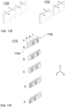
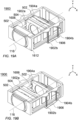
- FIG. 1A shows schematically a general perspective view of an embodiment of a dual-camera numbered 100, comprising an upright Wide camera 102, and a folded Tele camera 103 comprising an OPFE 104 (e.g. a prism), and a zoom folded Tele camera lens and sensor module (or simply "module") 106.
- Wide camera includes a Wide lens 110 with a fixed effective focal length EFLw.
- EFLw may be 2-5mm.
- OPFE 104 is held in a prism holder 108.
- Module 106 includes a shield 107. Shield 107 may cover some or all elements of module 106 or camera 103.
- FIG. 1B shows dual-camera 100 with shield 107 removed and with more details.
- Module 106 further includes a Tele lens 114 with a Tele lens optical axis 116, a Tele sensor 118, and, optionally, a glass window 130 (see e.g. FIG. 2A ).
- Glass window 130 may be used for filtering light at infra-red (IR) wavelengths, for mechanical protection of sensor 118 and/or for protection of sensor 118 from dust.
- IR infra-red
- the word "Tele" used with reference to the camera, lens or image sensor may be dropped henceforth.
- the lens and image sensor modules are separated, such that the Tele sensor has its own module, while other functionalities and parts described below (in particular lens actuator structure 502 of FIGS. 5A-E ) remain in a Tele camera lens module only.
- a system described herein may comprise one or mode additional cameras, forming e.g. a triple-camera system.
- a triple-camera may include also an Ultra-Wide camera, wherein an Ultra-Wide camera EFL, EFLuw ⁇ 0.7 ⁇ EFLw.
- Dual-camera 100 further comprises, or is coupled to, a controller (not shown) that controls various camera functions, including the movement of lens groups and elements described below.
- Lens 114 includes three groups of lens elements G1, G2 and G3, housed respectively in a first group (G1) lens housing (or “holder") 120, a second group (G2) lens housing 122 and a third group (G3) lens housing 124. Details of three different lens designs for lens element groups G1, G2 and G3 are provided below with reference to FIGS. 2-4 .
- at least one lens element group moves relative to another lens element group along lens optical axis 116 to provide at least two Tele lens effective focal lengths EFL T : a minimum EFL Tmin and a maximum EFL Tmax .
- EFL Tmin may be 10-20mm and EFL Tmax may be 20-40mm.
- EFL Tmin is larger than the EFLw, for example by 2 times or more, such that optical zoom may be provided by dual-camera 100 between EFLw and EFL Tmax .
- a Tele lens total track length (TTL T ) is defined as the distance along the optical axis from the first surface of the first lens element toward the object side (S 1 , see below) to the image sensor surface, when the lens is focused at infinity, and including all lens elements and the glass window.
- TTL Tmin is defined for the first zoom state and TTL Tmax is defined for the second zoom state.
- TTL Tmin and TTL Tmax are marked for example in FIGS. 2C, 2D , 3A and 3B , but the definitions apply for all embodiments in this application.
- a glass window 130 may be positioned between all lens elements and image sensor 118.
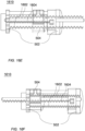
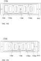
- FIG. 2C shows details of a lens 114' of the first optical design in the first zoom state
- FIG. 2D shows details of lens 114' in the second zoom state.
- Lens 114' has a first exemplary optical design, represented by Tables 1-4 and includes eight lens elements marked L1-L8, starting with L1 on an object side facing the prism ("object side") and ending with L8 on an image side toward the image sensor.
- Table 1 provides optical data for each of the surfaces in the optical lens design.
- the optical data of the OPFE (prism or mirror) is omitted from Table 1, as many OPFE designs known in the art can be used between the object and S 1 .
- Non-limiting examples of such OPFEs include: a prism made of glass or plastic, such that the refractive index of the prism may change (e.g. in a range of 1-3); an OPFE that limits stray light (e.g.
- Table 2 provides zoom data, which is additional data for distances between surfaces in Table 1, as well as changing parameters for various zoom positions.
- Table 3 provides aspheric data, which is additional optical data for surfaces in Table 1 that are not spherical.
- Table 4 provides lens elements and lens elements groups focal lengths in mm. Similar Tables exist for a second exemplary optical design (Tables 5-8), a third exemplary optical design (Tables 9-12) a fourth exemplary optical design (Tables 13-16) and a fifth exemplary optical design (Tables 17-20) below.
- Lenses disclosed in various exemplary embodiments below comprise several lens groups (G1, G2, G3, etc.) of lens elements, each group including a plurality of lens elements marked Li.
- Each lens element Li has a respective front surface S 2i-1 and a respective rear surface S 2i where "i" is an integer between 1 and N.
- the term "front surface” of each lens element refers to the surface of a lens element located closer to the entrance of the camera (camera object side) and the term “rear surface” refers to the surface of a lens element located closer to the image sensor (camera image side).
- the front surface and/or the rear surface can be in some cases aspherical.
- the front surface and/or the rear surface can be in some cases spherical.
- Lens elements L1 to LN may be made from various materials, for example plastic or glass. Some lens elements may be made of different materials than other lens elements.
- the notations “Gi”, “Li”, “S i” are shown in several figures as an example (see FIGS. 2C, 2D for "Gi” notations, FIG. 2B for “Li” notations and FIG. 4A for "S i " notations), however these notations apply for all embodiments in this application.
- optical axis Y direction in an exemplary coordinate system
- upper and bottom refers to a section of any part/element/group that is closer to and facing an imaged (photographed) object along Y relative to other sections of the same part/element or group.
- lower refers to a section of any part/element/group that is farthest from and facing away from an imaged object along Y relative to other sections of the same part/element or group.
- R is the radius of curvature of a surface and T is the distance from the surface to the next surface parallel to an optical axis. Since the distance between some lens elements change with zooming and focusing, additional thickness data is given in Tables 2, 6 and 10 for various zoom and focus positions. Note that the TTL T is the sum of all T values starting from S 1 and to the image sensor, when additional data from Tables 2, 6 and 10 is used with the object set at infinity.
- D is the optical diameter of the surface. D/2 expresses a "semi-diameter" or half of the diameter. The units of R, T, and D are millimeters (mm).
- Nd and Vd are the refraction index and Abbe number of the lens element material residing between the surface and the next surface, respectively.
- the diameter D of the image sensor as presented in the tables below refers to a possible size of the image sensor diagonal.
- Table 1 Group Lens Surface Type R [mm] T [mm] Nd Vd D [mm] Object S 0 Flat Infinity See Table 2 G1 L1 S 1 EVAS 5.997 1.224 1.4847 84.150 7.50 G1 L1 S 2 EVAS 13.606 2.104 7.50 G1 L2 S 3 EVAS -19.106 0.509 1.8446 23.750 6.73 G1 L2 S 4 EVAS -25.364 See Table 2 6.24 G2 L3 S 5 EVAS 11.959 0.864 1.5348 55.660 4.76 G2 L3 S 6 EVAS -9.715 0.422 4.76 G2 L4 S 7 EVAS -3.692 0.656 1.6510 21.510 4.40 G2 L4 S 8 EVAS -4.784 See Table 2 4.27 G3 L5 S 9 EVAS -8.017 0.719 1.6510 21.510 4.00 G3 L5
- lens elements L1-L8 are grouped into three groups: a first group G1 comprising lens elements L1 and L2, a second group G2 comprising lens elements L3 and L4 and a third group comprising lens elements L5-L8.
- the lens or group focal lengths listed in Table 4 have positive or negative values, which indicate respective positive or negative refractive powers of the associates lens elements or groups.
- L1, L3, L5 and L8 have positive refractive powers and L2, L4, L6 and L7 have negative refractive powers
- G1 and G2 have positive refractive powers and G3 has negative refractive power. This applies also to Tables 8 and 12.
- Example 1 the camera is brought into two zoom states by moving groups G1 and G3 relative to image sensor 118 while keeping group G2 stationary relative to image sensor 118. G3 is then further movable for focusing in each of the zoom states.
- Table 2 specifies the exact distances and relative positioning.
- the range of movement may be for example 5-10mm.
- G1 is separated from G2 by a distance d4 (the distance between S 4 and S 5 in Table 2 for a case of 15mm EFL, i.e. 0.131mm)
- G2 is separated from G3 by a distance d8 (the distance between S 8 and S 9 in Table 2 for a case of 15mm EFL, i.e.
- G3 is separated from window 130 by a distance d16 (the distance between S 16 and S 17 in Table 2 for a case of 15mm EFL, i.e. 1.094 to 0.810 mm, depending on the focus distance).
- G1 is separated from G2 by a distance d4' (the distance between S 4 and S 5 in Table 2 for a case of 30mm EFL, i.e. 11.403mm)
- G2 is separated from G3 by a distance d8' (the distance between S 8 and S 9 in Table 2 for a case of 30mm EFL, i.e.
- d16' the distance between S 16 and S 17 in Table 2 for a case of 30mm EFL, i.e. 6.114mm to 5.740mm depending on the focus distance.
- FIG. 3A shows details of the lens elements of a second embodiment of an exemplary optical design in a folded Tele camera such as camera 103 in a first zoom state
- FIG. 3B shows details of the lens elements of the second optical design in a second zoom state
- the figures show a lens 114", image sensor 118 and optional window 130.
- the second optical design is represented by Tables 5-8 and includes eight lens elements marked L1-L8, starting with L1 on an object side facing the prism and ending with L8 on an image side toward the image sensor.
- Table 5 provides optical data
- Table 6 provides zoom data
- Table 7 provides aspheric data
- Table 8 provides lens or group focal length in mm.
- lens elements L1-L8 are grouped into three groups: a first group G1 comprising lens elements L1 and L2, a second group G2 comprising lens elements L3-L5, and a third group comprising lens elements L6-L8.
- Example 2 the camera is brought into two zoom states by moving groups G1 and G3 together relative to the image sensor in a given range R 1,3 while moving group G2 relative to the image sensor in a range R 2 smaller than R 1,3 .
- R 1,3 7.509mm
- R 2 1.574mm.
- Group G2 is further movable at any zoom state relative to the image sensor in a range R AF for changing the focal distance of camera 106 from infinity down to 1 meter.
- R AF may be up to 550 micrometers (um), depending on zoom state.
- R 1,3 and R 2 are smaller than 0.6 ⁇ (EFL Tmax - EFL Tmin ) and of course smaller than 0.75 ⁇ (EFL Tmax - EFL Tmin ).
- F# Tmin is smaller than 1.0 ⁇ F# Tmax ⁇ EFL Tmin / EFL Tmax , smaller than 1.2 ⁇ F# Tmax ⁇ EFL Tmin / EFL Tmax , smaller than 1.5 ⁇ F# Tmax ⁇ EFL Tmin / EFL Tmax and smaller than 1.8 ⁇ F# Tmax ⁇ EFL Tmin / EFL Tmax .
- G1 is separated from G2 by a distance d4 (the distance between S 4 and S 5 in Table 6 for a case of 15mm EFL, i.e. 1.246 to 1.012 mm, depending on the focus distance)
- G2 is separated from G3 by a distance d10 (the distance between S 10 and S 11 in Table 6 for a case of 15mm EFL, i.e. 6.136-6.370 mm, depending on the focus distance)
- G3 is separated from window 130 by a distance d16 (the distance between S 16 and S 17 in Table 6 for a case of 15mm EFL, i.e. 0.229 mm,).
- G1 is separated from G2 by a distance d4' (the distance between S 4 and S 5 in Table 6 for a case of 30mm EFL, i.e. 7.181 to 6.658 mm, depending on the focus distance)
- G2 is separated from G3 by a distance d10' (the distance between S 10 and S 11 in Table 6 for a case of 30mm EFL, i.e. 0.2 to 0.725 mm, depending on the focus distance)
- G3 is separated from window 130 by a distance d16' (the distance between S 16 and S 17 in Table 6 for a case of 30mm EFL, i.e. 7.738 mm).
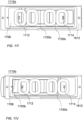
- FIG. 4A shows details of the lens elements of a third embodiment of an exemplary optical design in a folded Tele camera such as camera 103 in a first zoom state
- FIG. 4B shows details of the lens elements of the third optical design in a second zoom state.
- the figures show a lens 114′′′ , image sensor 118 and optional window 130.
- the second optical design is represented by Tables 9-12 and includes eight lens elements marked L1-L8, starting with L1 on an object side facing the prism and ending with L8 on an image side toward the image sensor.
- Table 9 provides optical data
- Table 10 provides zoom data
- Table 11 provides aspheric data
- Table 12 provides lens or group focal length in mm.
- lens elements L1-L8 are grouped into three groups: a first group G1 comprising lens elements L1 and L2, a second group G2 comprising lens elements L3 and L4, and a third group comprising lens elements L5-L8.
- Example 3 the camera is brought into two zoom states by moving groups G1 and G3 relative to the image sensor in a given range while keeping group G2 stationary.
- the range of movement may be for example 5-10mm.
- G1 is further movable for focusing.
- G1 is separated from G2 by a distance d4 (the distance between S 4 and S 5 in Table 10 for a case of 15mm EFL, i.e. 0.199-0.870 mm, depending on the focus distance)
- G2 is separated from G3 by a distance d8 (the distance between S 8 and S 9 in Table 10 for a case of 15mm EFL, i.e. 6.050 mm)
- G3 is separated from window 130 by a distance d16 (the distance between S 16 and S 17 in Table 10 for a case of 15mm EFL, i.e.
- G1 is separated from G2 by a distance d4 (the distance between S 4 and S 5 in Table 10 for a case of 30mm EFL, i.e. 10.377-11.031 mm, depending on the focus distance)
- G2 is separated from G3 by a distance d8 (the distance between S 8 and S 9 in Table 10 for a case of 30mm EFL, i.e. 0.06 mm,)
- G3 is separated from window 130 by a distance d16 (the distance between S 16 and S 17 in Table 10 for a case of 30mm EFL, i.e. 6.64 mm).
- FIG. 4C shows details of the lens elements of a fourth exemplary optical design in a folded Tele camera such as camera 103 in a first zoom state
- FIG. 4D shows details of the lens elements of the fourth optical design in a second zoom state
- the figures show a lens 114 ⁇ , image sensor 118 and optional window 130.
- the second optical design is represented by Tables 13-16 and includes eight lens elements marked L1-L8, starting with L1 on an object side facing the prism and ending with L8 on an image side toward the image sensor.
- Table 13 provides optical data
- Table 14 provides zoom data
- Table 15 provides aspheric data
- Table 16 provides lens or group focal length in mm.
- lens elements L1-L8 are grouped into three groups: a first group G1 comprising lens elements L1 and L2, a second group G2 comprising lens elements L3-L5, and a third group comprising lens elements L6-L8.
- Example 4 the camera is brought into two zoom states by moving groups G1 and G3 together (as one unit) relative to the image sensor in a given range R 1,3 while group G2 is stationary relative to the image sensor in the zoom process.
- R 1,3 7.065mm. While group G2 does not move when changing zoom state, group G2 is movable at any zoom state relative to the image sensor and groups G1 and G3 in a range R AF for changing the focal distance of camera 106 from infinity down to 1 meter.
- R AF may be up to 730 ⁇ m, depending on zoom state.
- G1 is separated from G2 by a distance d4 (the distance between S 4 and S 5 in Table 14 for a case of 15mm EFL
- G2 is separated from G3 by a distance d10 (the distance between S 10 and S 11 in Table 14 for a case of 15mm EFL
- G3 is separated from window 130 by a distance d16 (the distance between S 16 and S 17 in Table 14 for a case of 15mm EFL.
- G1 is separated from G2 by a distance d4' (the distance between S 4 and S 5 in Table 14 for a case of 30mm EFL)
- G2 is separated from G3 by a distance d10' (the distance between S 10 and S 11 in Table 14 for a case of 30mm EFL)
- G3 is separated from window 130 by a distance d16' (the distance between S 16 and S 17 in Table 14 for a case of 30mm EFL).
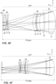
- FIG. 4E shows details of the lens elements of a fifth exemplary optical design in a folded Tele camera such as camera 103 in a first zoom state
- FIG. 4F shows details of the lens elements of the fifth optical design in a second zoom state.
- the figures show a lens 114′′′ ⁇ , image sensor 118 and optional window 130.
- the second optical design is represented by Tables 17-20 and includes eight lens elements marked L1-L8, starting with L1 on an object side facing the prism and ending with L8 on an image side toward the image sensor.
- Table 17 provides optical data
- Table 18 provides zoom data
- Table 19 provides aspheric data
- Table 20 provides lens or group focal length in mm.
- lens elements L1-L8 are grouped into three groups: a first group G1 comprising lens elements L1 and L2, a second group G2 comprising lens elements L3-L5, and a third group comprising lens elements L6-L8.
- Example 5 the camera is brought into two zoom states by moving groups G1 and G3 together (as one unit) relative to the image sensor in a given range R 1,3 while group G2 is stationary relative to the image sensor.
- R 1,3 7.697mm.
- Groups G1+G3 is further movable together at any zoom state relative to the image sensor and group G2 in a range R AF for changing the focal distance of camera 106 from infinity down to 2 meter.
- R AF may be up to 1.8 mm, depending on zoom state.
- G1 is separated from G2 by a distance d4 (the distance between S 4 and S 5 in Table 18 for a case of 15mm EFL)
- G2 is separated from G3 by a distance d10 (the distance between S 10 and S 11 in Table 18 for a case of 15mm EFL)
- G3 is separated from window 130 by a distance d16 (the distance between S 16 and S 17 in Table 18 for a case of 15mm EFL).
- G1 is separated from G2 by a distance d4' (the distance between S 4 and S 5 in Table 18 for a case of 30mm EFL)
- G2 is separated from G3 by a distance d10' (the distance between S 10 and S 11 in Table 18 for a case of 30mm EFL)
- G3 is separated from window 130 by a distance d16' (the distance between S 16 and S 17 in Table 17 for a case of 30mm EFL).
- FIG. 4G shows details of the lens elements of a sixth embodiment of an exemplary optical design in a folded Tele camera such as camera 103 in a first zoom state
- FIG. 4H shows details of the lens elements of the sixth optical design in a second zoom state.
- the figures show a lens 114′′′′′′ , image sensor 118 and optional window 130.
- the sixth optical design is represented by Tables 21-24 and includes eight lens elements marked L1-L8, starting with L1 on an object side facing the prism and ending with L8 on an image side toward the image sensor.
- Table 21 provides optical data
- Table 22 provides zoom data
- Table 23 provides aspheric data
- Table 24 provides lens or group focal length in mm.
- lens elements L1-L8 are grouped into three groups: a first group G1 comprising lens elements L1, L2 and L3, a second group G2 comprising lens elements L4, L5 and L6, and a third group comprising lens elements L7 and L8.
- Example 6 the camera is brought into two zoom states by moving groups G1 and G3 together (as one unit) relative to the image sensor in a given range R 1,3 while group G2 moves in a range R 2 relative to the image sensor, whereas R 2 ⁇ R 1,3 .
- Groups G1+G2+G3 is further movable together at any zoom state relative to the image sensor and in a range R AF for changing the focal distance of camera 106 from infinity down to 1 meter or down to 2 meter.
- R AF may be up to 0.4mm, depending on zoom state.
- G1 is separated from G2 by a distance d7 (the distance between S 7 and S 8 in Table 22 for a case of 13mm EFL)
- G2 is separated from G3 by a distance d13 (the distance between S 13 and S 14 in Table 22 for a case of 13mm EFL)
- G3 is separated from window 130 by a distance d17 (the distance between S 17 and S 18 in Table 22 for a case of 13mm EFL).
- G1 is separated from G2 by a distance d7' (the distance between S 7 and S 8 in Table 22 for a case of 26mm EFL)
- G2 is separated from G3 by a distance d13' (the distance between S 13 and S 14 in Table 22 for a case of 26mm EFL)
- G3 is separated from window 130 by a distance d17' (the distance between S 17 and S 18 in Table 21 for a case of 26mm EFL).
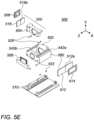
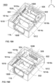
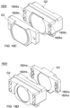
- FIG. 5A-E show schematically an example for Tele lens and sensor module (or simply "module") numbered 500.
- module 500 has the optical design of the second example.
- FIG. 5A shows schematically module 500 in an EFL Tmin state from a top perspective view
- FIG. 5B shows schematically module 500 in the EFL Tmin state from another top perspective view
- FIG. 5C shows schematically module 500 in an EFL Tmax state from one top perspective view
- Module 500 comprises a G1+G3 lens sub-assembly 502, a G2 lens sub-assembly 504, a sensor sub-assembly 506, an electro-magnetic (EM) sub-assembly 508, a base sub-assembly 510, a first magnet 512, a first coil 514, a second magnet 516, a first set of (exemplarily 4) balls 520 and a second set of (exemplarily 4) balls 522.
- Lens sub-assemblies 502 and 504 share lens optical axis 116.
- First coil 514 is positioned next to first magnet 512 and is rigidly coupled to (not moving relative to) base sub-assembly 510.
- First coil 514 may be soldered to a PCB such as PCB 822 ( FIG. 8 ), or routed to external circuitry (not shown) which allows sending input and output currents to first coil 514, the currents carrying both power and electronic signals required for operation.
- Coil 514 has exemplarily a rectangular shape and typically includes a few tens of coil windings (i.e. in a non-limiting range of 50-250), with a typical resistance of 10-30 ohm.
- First magnet 512 is a split magnet, such that a split line 512a in the middle separates it into two sides: in one side of split line 512a, magnet 512 has a north magnetic pole facing the positive X direction, and in the other side of split line 512a, magnet 512 has a south magnetic pole facing the positive X direction.
- a first Lorentz force is created on first magnet 512.
- a current flow through first coil 514 in a clockwise direction will induce a first Lorentz force in the positive Z direction on first magnet 512
- a current flow through first coil 512 in a counter clockwise direction will induce a Lorentz force in the negative Z direction on first magnet 512.
- first Lorentz force may be used to move bottom actuated sub-assembly 560 from the first zoom state to the second zoom state and vice-versa in an open loop control, i.e. actuate bottom actuated sub-assembly 560 between stops 720a-b and 722a-b (see below).
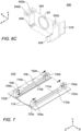
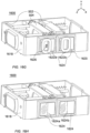
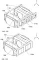
- FIGS. 6A and 6B provide two bottom perspective views of actuated parts of module 500, showing a top actuated sub-assembly 550 and a bottom actuated sub-assembly 560 in the EFL Tmin state.
- FIG. 6C shows top actuated sub-assembly 550 from a bottom perspective view.
- Top actuated sub-assembly 550 comprises G2 lens sub-assembly 504, second magnet 516 and a plurality of stepping magnets 626.
- Bottom actuated sub-assembly 560 comprises G1+G3 lens sub-assembly 502, first magnet 512, stepping magnets 628 and four yokes 602a-b ( FIG.
- FIG. 7 shows details of base sub-assembly 510, which comprises guiding rails 710a and 710b and pull-stop magnets 702a-b and 704a-b. Note that in FIG. 7 , pull-stop magnets 702a-b and 704a-b are separated from stops 720a-b and 722a-b for illustration purposes. Arrows show the gluing position of pull-stop magnets 702a-b and 704a-b in stops 720a-b and 722a-b. Yokes 602a-b are pulled against pull-stop magnets 702a-b and yokes 604a-b are pulled against pull-stop magnets 704a-b.
- Each of guiding rails 710a-b comprises a respective groove 712a-b.
- Base sub-assembly 510 further comprises two mechanical stops 706 and 708, which are exemplarily connected to guiding rail 710b. Mechanical stops 706 and 708 limit the stroke of top actuated sub-assembly 550.
- FIG. 8 shows details of EM sub-assembly 508 on PCB 822.
- module 500 enables a relative motion of lens sub-assemblies 502 and 504 in a direction along lens optical axis 116.
- Module 500 has exemplary length/width/height dimensions in the range of 3-40 mm, i.e. module 500 can be contained in a box with dimension of 3x3x3 mm 3 to 40x40x40 mm 3 .
- module 500 has a height (along Y axis) which is limited by the maximal clear apertures of lens elements L1....LN plus the plastic thickness of respective lens sub-assemblies 502 and 504 (the plastic thickness is for example in the range 0.5-1.5mm), plus the thickness of shield 107 (the shield thickness is for example in the range 0.1-0.3mm), plus the thickness of two airgaps between respective lens sub-assemblies 502 and 504 and shield 107 (each air gap thickness is for example in the range of 0.05-0.15mm).
- the clear aperture of lens elements L1....LN may be a circular or cut-lens clear aperture, as described below.
- lens sub-assembly 502 that holds lens groups G1+G3
- lens sub-assembly 504 that holds lens group G2.
- Lens sub-assemblies 502 and 504 are typically made of plastic.
- lens sub-assembly 502 and lens groups G1+G3 may be a single part (and similarly lens sub-assembly 504 and G2 may be a single part). In some embodiments, they may be separate parts.
- Lens sub-assemblies 502 and 504 may be made, for example, by plastic molding, or alternatively by other methods.
- First and second magnets 512 and 516 are fixedly attached (e.g. glued) to lens sub-assemblies 502 and 504, respectively, from two opposite sides across lens optical axis 116 (X direction).
- Lens sub-assembly 502 includes several grooves, defining a mechanical ball-guided mechanism, allowing actuation in a linear rail for the zoom needs.
- six grooves are described, but another number of grooves may be used: two grooves 542a-b ( FIG. 5E ) on a top surface of lens sub-assembly 502 along the Z direction, and four grooves 624a-d ( FIG. 6A ) on a bottom surface of lens sub-assembly 502, along the Z direction as well.
- Lens sub-assembly 504 includes several groves, mating with some of the grooves of lens sub-assembly 502.
- lens sub-assembly 504 includes four grooves 642a-d, only three of which are seen in FIG. 6C .
- Grooves 642a-d are parallel to each other, are along the Z-axis (optical axis), and are used to guide top actuated sub-assembly 550 along the Z direction.
- Top actuated sub-assembly 550 is positioned on top of bottom actuated sub-assembly 560 such that grooves 642a-b (642c-d) are right above and parallel to grooves 542a (542b).
- module 500 may have more than four balls between lens sub-assemblies 502 and 504, for example up to 7 balls per side or up to 14 balls in total.
- Balls 520 may be made from aluminum oxide or another ceramic material, from a metal or from a plastic material. Typical ball diameters may be in a non-limiting range of 0.3-1mm. Other ball sizes and positioning considerations may be, as in co-owned international PCT patent application PCT/ IB2017/052383 titled "Rotational Ball Guided Voice Coil Motor".
- lens sub-assemblies 502 and 504 are exemplarily plastic molded, there is some tolerance allowed in part dimensions, typically a few tens of microns or less for each dimension. This tolerance may lead to positional misalignment between adjacent (facing) grooves 542a-b and 642a-d.
- some grooves e.g. 542a-b and 642c-d
- Grooves 542b and 642c-d are aligned during assembly, while the alignment of grooves 542a and 642a-b have a small clearance due to the trapezoid cross section of the latter grooves.
- the trapezoid groove cross sections are just exemplary, and other groove cross section shapes may be used (e.g. rectangular, flat, etc.), such that one pair of grooves is well aligned by the groove shape and the other pair of grooves has clearance of alignment.
- lens sub-assembly 504 is molded as one part and the alignment of G1 to G3 is based on the plastic molding tolerances. In some embodiments lens sub-assembly 504 is molded as several parts which are glued in the factory using active or passive alignment procedures. G2 is aligned to G1 and G3 using a single groove pair (542b and 642c and / or 642d), i.e. lens sub-assemblies 502 and 504 are aligned to each other without intermediate parts.
- module 500 may have more than four balls, for example up to 7 balls per side or up to 14 balls in total.
- the size, material and other considerations related to balls 522 are similar to those of balls 520.
- Other considerations regarding grooves 712a-b and 624a-d are similar to those of grooves 542a-b and 642a-d as described above.
- Module 500 further includes several ferromagnetic yokes 716 ( FIG. 7 ) fixedly attached (e.g. glued) to base sub-assembly 510 such that each yoke is positioned below (along Y direction) three of stepping magnets 626 and 628.
- ferromagnetic yokes 716 may be a fixedly part of shield 107.
- shield 107 by itself may be made from ferromagnetic material, or the bottom part of shield 107 may be made of ferromagnetic material, such that the yoke(s) is (are) part of the shield.
- Each ferromagnetic yoke 716 pulls some of stepping magnets 626 or 628 by magnetic force in the negative Y direction, and thus all yokes prevent both top actuated sub-assembly 550 and bottom actuated sub-assembly 560 from detaching from each other and from base 510 and shield 107.
- Balls 520 prevent top actuated sub-assembly 550 from touching bottom actuated sub-assembly 560 and balls 522 prevent bottom actuated sub-assembly 560 from touching base sub-assembly 510.
- Both top actuated sub-assembly 550 and bottom actuated sub-assembly 560 are thus confined along the Y-axis and do not move in the Y direction.
- the groove and ball structure further confines top actuated sub-assembly 550 and bottom actuated sub-assembly 560 to move only along lens optical axis 116 (Z-axis).
- FIG. 7 shows details of base sub-assembly 510 and stationary rails in module 500.
- top actuated sub-assembly 550 is limited to move between mechanical stops 706 and 708, with a distance equal to the required stroke of G2 (about 1-3mm) between them.
- bottom actuated sub-assembly 560 is limited to move between mechanical stops 720a-b and 722a-b, and / or pull-stop magnets 702a-b and 704a-b.
- FIG. 8 shows details of EM sub-assembly 508 in module 500.
- EM sub-assembly 508 includes second coil 818, two Hall bar elements ("Hall sensors") 834a and 834b and a PCB 822.
- Second Coil 818 and Hall bar elements 834a-b may be soldered (each one separately) to PCB 822.
- Second Coil 818 has exemplarily a rectangular shape and typically includes a few tens of coil windings (e.g. in a non-limiting range of 50-250), with a typical resistance of 10-40 ohms.
- PCB 822 allows sending input and output currents to second coil 818 and to Hall bar elements 834a-b, the currents carrying both power and electronic signals required for operation.
- PCB 822 may be connected electronically to the external camera by wires (not shown).
- EM sub-assembly 508 is positioned next to second magnet 516.
- Second magnet 516 is a split magnet, separated by a split line 516a in the middle into two sides: in one side of split line 516a, magnet 516 has a north magnetic pole facing the positive X direction, and in the other side of split line 516a, magnet 516 has a south magnetic pole facing the positive X direction.
- a Lorentz force is created on second magnet 516.
- a current flow through second coil 818 in a clockwise direction will induce a Lorentz force in the positive Z direction on second magnet 516, while a current flow through second coil 818 in a counter clockwise direction will induce a Lorentz force in the negative Z direction on second magnet 516.
- Hall bar elements 834a-b are designed to measure magnetic the field in the X direction (intensity and sign) in the center of each Hall bar element. Hall bar elements 834a-b can sense the intensity and direction of the magnetic field of second magnet 516. In an example, the positioning of Hall bar element 834a on PCB 822 is such that:
- Hall bar element 834a can measure the respective position of second magnet 516 along the Z direction when the system is in the first zoom state, since in the first zoom state the X direction magnetic field has measurable gradient on Hall bar 834a trajectory along R AF between focus positions of infinity to 1 meter focus, and X direction magnetic field may be correlated to position.
- Hall bar element 834b can measure the respective position of second magnet 516 along the Z direction when the system is in the second zoom state, since in the second zoom state the X direction magnetic field has measurable gradient on Hall bar 834b trajectory along R AF between focus positions of infinity to 1 meter focus, and X direction magnetic field may be correlated to position.
- a control circuit may be implemented in an integrated circuit (IC) to control in closed loop the position of second magnet 516 relative to EM sub-assembly 508 (and to base sub-assembly 510 to which EM sub-assembly 508 is rigidly coupled) while operating in either zoom states, and in open loop while traveling between zoom state (see FIG. 10 and description below)
- the IC may be combined with one or both Hall elements 834a-b.
- the IC may be a separate chip, which can be located outside or inside module 500 (not shown).
- all electrical connections required by module 500 are connected to EM sub-assembly 508, which is stationary relative to base sub-assembly 510 and to the external world. As such, there is no need to transfer electrical current to any moving part.
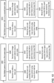
- FIG. 10 illustrates such an exemplary method in a flow chart.
- Tele camera 103 is positioned with lens 114 in one (e.g. a first) zoom state.
- a decision (by a user or an algorithm) to refocus Tele lens 114 is made in step 1004, and G2 lens sub-assembly 504 is moved in step 1006 under closed loop control (by a controller - not shown) using inputs from Hall bar element 834a to bring Tele camera 103 into another focus position in the first zoom state.
- a decision (by a user or an algorithm) to change the zoom state of lens 114 of camera 103 to another (e.g.
- a second zoom state is made in step 1008, and G1+G3 lens sub-assembly 502 is moved under open loop control to mechanical stop 720 in step 1010, followed by movement of G2 lens sub-assembly 504 under open loop control to mechanical stop 706 in step 1012. G2 lens sub-assembly 504 is then moved under closed loop control using inputs from Hall bar element 834b in step 1014, to bring Tele folded camera 103 into the second zoom state in yet another focus position in step 1016. A decision to refocus lens 114 is made in step 1018. The refocusing of lens 114 in the second zoom state is performed by moving G2 lens sub-assembly under closed loop control using inputs from Hall bar element 834b.
- a decision (by a user or an algorithm) to change the second zoom state of lens 114 of camera 103 to the first zoom state is made in step 1020, and G1+G3 lens sub-assembly 502 is moved under open loop control to mechanical stop 722 in step 1022, followed by movement of G2 lens sub-assembly 504 under open loop control to mechanical stop 708 in step 1024.
- the two surfaces S 2i-1 , S 2i of any lens element L i may have two apertures that include two cuts (facets).
- lens element L i is referred to as a "cut lens element".
- the cuts enable the lens assembly to be lower and/or shorter.
- FIG. 9A shows a lens element 902 having axial symmetry and a height H 902
- FIG. 9B shows a cut lens element 904 with two cuts 906 and 908 and with height H 904 .
- Lens elements 902 and 904 have the same diameter D.
- the first two lens elements (L 1 and L 2 ) are cut lens elements.
- a clear height value CH(S k ) can be defined for each surface S k for 1 ⁇ k ⁇ 2N), and a clear aperture value CA(S k ) can be defined for each surface S k for 1 ⁇ k ⁇ 2N).
- CA(S k ) and CH(S k ) define optical properties of each surface S k of each lens element.
- each optical ray that passes through a surface S k impinges this surface on an impact point IP.
- Optical rays enter the lens module (e.g. 114', 114", 114"' ) from surface S 1 , and pass through surfaces S 2 to S 2N consecutively.
- Some optical rays can impinge on any surface S k but cannot /will not reach image sensor 118.
- For a given surface S k only optical rays that can form an image on image sensor 118 are considered forming a plurality of impact points IP are obtained.
- CH(S k ) is defined as the distance between two closest possible parallel lines (see lines 1200 and 1202 in FIG. 12 located on a plane P orthogonal to the optical axis of the lens elements (in the representation of FIGS. 11A and 11B , plane P is parallel to plane X-Y and is orthogonal to optical axis 116 ), such that the orthogonal projection IP orth of all impact points IP on plane P is located between the two parallel lines.
- CH(S k ) can be defined for each surface S k (front and rear surfaces, with 1 ⁇ k ⁇ 2N).
- CH(S k ) does not depend on the object currently imaged, since it refers to the optical rays that "can” form an image on the image sensor. Thus, even if the currently imaged object is located in a black background which does not produce light, the definition does not refer to this black background since it refers to any optical rays that "can” reach the image sensor to form an image (for example optical rays emitted by a background which would emit light, contrary to a black background).
- FIG. 11A illustrates the orthogonal projections IP orth,1 , IP orth,2 of two impact points IP 1 and IP 2 on plane P which is orthogonal to optical axis 116.
- surface S k is convex.
- FIG. 11B illustrates the orthogonal projections IP orth,3 , IP orth,4 of two impact points IP 3 and IP 4 on plane P.
- surface S k is concave.
- the orthogonal projection IP orth of all impact points IP of a surface S k on plane P is located between parallel lines 1200 and 1202.
- CH(S k ) is thus the distance between lines 1200 and 1202.
- a clear aperture CA(S k ) is defined for each given surface S k (for 1 ⁇ k ⁇ 2N), as the diameter of a circle, wherein the circle is the smallest possible circle located in a plane P orthogonal to the optical axis 116 and encircling all orthogonal projections IP orth of all impact points on plane P.
- CA(S k ) also does not depend on the object which is currently imaged.
- the circumscribed orthogonal projection IP orth of all impact points IP on plane P is circle 1300.
- the diameter of this circle 1300 defines CA(S k ).
- zoom cameras disclosed herein are designed to overcome certain optical challenges as follows:
- Table 25 summarizes the movements in each Example, with exemplary movement ranges: Table 25 Example 1 Example 2 Example 3 Example 4 Example 5 Example 6 G1 range [mm] 11.272 7.52 10.18 7.065 7.697 5.641 G2 range [mm] Static 1.575 Static Static Static 0.718 G3 range [mm] 5.02 7.52 6.0 7.065 7.697 5.641 Group moving for focus G3 G2 G1 G2 G1+G3 G1+G2+G3 AF max range [mm] 0.375 0.525 0.68 0.723 1.742 0.342
- Examples presented in Table 25 where more than one lens group is indicated as moving for focus may refer to a design where the lens groups defined in the table move together as one unit for focus. In some embodiments (e.g. Examples 5 and 6), moving several lens groups together may be facilitated by coupling the respective lens groups rigidly.
- G1 range, G2 range and G3 range refer to the maximal range of overall movement of the lens groups with respect to the image sensor.
- AF max range refers to the maximal range of movement of the lens groups with respect to the image sensor defined in row "Group moving for focus” required for focusing between infinity and 1 meter or 2 meter according to the respective relevant table of table 2, 6, 10, 14, 18, 22 see above.
- the AF max range is given by the lens group movement for the higher zoom state, i.e. the state with EFL Tmax .
- G1 and G3 may be in a stationary state, i.e. G1 and G3 do not move, whereas G2 may be moved in order to change zoom state.
- FIG. 14 shows schematically an embodiment of an electronic device numbered 1400 and including multi-aperture cameras with at least one multi-zoom state camera disclosed herein.
- Electronic device 1400 comprises a first camera module 1410 that includes an OPFE 1412, and a first lens module 1414 that forms a first image recorded by a first image sensor 1416.
- a first lens actuator 1418 may move lens module 1414 for focusing and/or optical image stabilization (OIS) and/or for changing between two different zoom states.
- electronic device 1400 may further comprise an application processor (AP) 1440.
- a first calibration data may be stored in a first memory 1422 of a camera module, e.g. in an EEPROM (electrically erasable programmable read only memory).
- EEPROM electrically erasable programmable read only memory
- a first calibration data may be stored in a third memory 1450 such as a NVM (non-volatile memory) of the electronic device 1400.
- the first calibration data may include one or more subsets of calibration data, e.g. a first subset comprising calibration data between sensors of a Wide and a Tele camera in a first zoom state, and/or a second subset comprising calibration data between sensors of a Wide and a Tele camera in a second zoom state, and/or a third subset comprising calibration data between a sensor of a Tele camera in a first zoom state and the same sensor in a second zoom state.
- Electronic device 1400 further comprises a second camera module 1430 that includes a second lens module 1432 that forms an image recorded by a second image sensor 1434.
- a second lens actuator 1436 may move lens module 1432 for focusing and/or OIS and/or for changing between two different zoom states.
- second calibration data may be stored at a second memory 1438 of a camera module.
- the second calibration data may be stored in a third memory 1450 of the electronic device 1400.
- the second calibration data may include one or more subsets of calibration data, e.g. as described above.
- a processing unit such as AP 1440 may receive respective first and second image data from camera modules 1410 and 1430 and supply camera control signals to the camera modules 1410 and 1430.
- AP 1440 may receive calibration data from a third memory 1450.
- an AP 1440 may receive calibration data stored respective in a first memory located on camera module 1410 and in a second memory located on camera module 1430.
- AP 1440 may receive calibration data stored respective in a first memory located on camera module 1410 and in a second memory located on camera module 1430, as well as from a third memory 1450 of an electronic device 1400.
- an electronic device like device 1400 may comprise more than one camera module realized in a folded lens design and with an OPFE. In other embodiments, two or more camera modules may be realized without an OPFE and not with a folded lens design structure, but with another lens design structure.
- AP 1440 may have access to data stored in third memory 1450. This data may comprise a third calibration data.
- An image generator 1444 may be a processor configured to output images based on calibration data and-image data. Image generator 1444 may process a calibration data and an image data in order to output an output image.
- Camera calibration data may comprise:
- FIG. 15A shows schematically an embodiment of a dual-aperture zoom camera with auto-focus AF and numbered 1500, in a general isometric view, and a sectioned isometric view.
- Camera 1500 comprises two sub-cameras, labeled 1502 and 1504, each sub-camera having its own optics.
- sub-camera 1502 includes an optics bloc 1506 with an aperture 1508 and an optical lens module 1510, as well as a sensor 1512.
- sub-camera 1504 includes an optics bloc 1514 with an aperture 1516 and an optical lens module 1518, as well as a sensor 1520.
- Each optical lens module may include several lens elements as well as an Infra-Red (IR) filter 1522a and 1522b.
- IR Infra-Red
- the two sub-cameras are positioned next to each other, with a baseline 1524 between the center of the two apertures 1508 and 1516.
- Each sub-camera can further include an AF mechanism and/or a mechanism for optical image stabilization (OIS), respectively 1526 and 1528, controlled by a controller (not shown).
- OIS optical image stabilization
- FIG. 15B shows schematically an embodiment of a zoom and auto-focus dual-aperture camera 1530 with folded Tele lens in a sectioned isometric view related to a XYZ coordinate system.
- Camera 1530 comprises two sub-cameras, a Wide sub-camera 1532 and a Tele sub-camera 1534.
- Wide camera 1532 includes a Wide optics bloc with a respective aperture 1538 and a lens module 1540 with a symmetry (and optical) axis 1542 in the Y direction, as well as a Wide image sensor 1544.
- Tele camera 1534 includes a Tele optics bloc with a respective aperture 1548 and an optical lens module 1550 with a Tele lens symmetry (and optical) axis 1552a , as well as a Tele sensor 1554.
- Camera 1530 further comprises an OPFE 1556.
- the Tele optical path is extended from an object (not shown) through the Tele lens to the Tele sensor and marked by arrows 1552b and 1552a .
- Various camera elements may be mounted on a substrate 1562 as shown here, e.g. a printed circuit board (PCB), or on different substrates (not shown).
- PCB printed circuit board
- FIG. 15C shows schematically an embodiment in a general isometric view of a zoom and auto-focus triple-aperture camera 1570 with one folded Tele sub-camera 1534.
- Camera 1570 includes for example elements and functionalities of camera 1530. That is, camera 1570 includes a Wide sub-camera 1532, a Tele sub-camera 1534 with an OPFE 1556.
- Camera 1570 further includes a third sub-camera 1572 which may be an Ultra-Wide camera with an Ultra-Wide lens 1574 and an image sensor 1578. In other embodiments, third sub-camera 1572 may have an EFL M and a FOV M intermediate to those of the Wide and Tele sub-cameras.
- a symmetry (and optical) axis 1576 of the third sub-camera is substantially parallel to axis 1542 sub-camera 1532. Note that while the first and the third sub-cameras are shown in a particular arrangement (with third sub-camera 1572 closer to Tele sub-camera 1534 ), this order may be changed such that the Wide and the Ultra-Wide sub-cameras may exchange places.
Landscapes
- Physics & Mathematics (AREA)
- General Physics & Mathematics (AREA)
- Engineering & Computer Science (AREA)
- Multimedia (AREA)
- Signal Processing (AREA)
- Optics & Photonics (AREA)
- Human Computer Interaction (AREA)
- Lenses (AREA)
- Studio Devices (AREA)
- Cameras In General (AREA)
- Details Of Cameras Including Film Mechanisms (AREA)
- Lens Barrels (AREA)
Applications Claiming Priority (4)
| Application Number | Priority Date | Filing Date | Title |
|---|---|---|---|
| US201962787826P | 2019-01-03 | 2019-01-03 | |
| US201962809871P | 2019-02-25 | 2019-02-25 | |
| PCT/IB2020/050002 WO2020141466A1 (en) | 2019-01-03 | 2020-01-01 | Multi-aperture cameras with at least one two state zoom camera |
| EP20735934.0A EP3738303B1 (de) | 2019-01-03 | 2020-01-01 | Multiblendenkameras mit mindestens einer zweizustands-zoom-kamera |
Related Parent Applications (1)
| Application Number | Title | Priority Date | Filing Date |
|---|---|---|---|
| EP20735934.0A Division EP3738303B1 (de) | 2019-01-03 | 2020-01-01 | Multiblendenkameras mit mindestens einer zweizustands-zoom-kamera |
Publications (2)
| Publication Number | Publication Date |
|---|---|
| EP4471485A2 true EP4471485A2 (de) | 2024-12-04 |
| EP4471485A3 EP4471485A3 (de) | 2025-01-15 |
Family
ID=71407202
Family Applications (2)
| Application Number | Title | Priority Date | Filing Date |
|---|---|---|---|
| EP24207348.4A Pending EP4471485A3 (de) | 2019-01-03 | 2020-01-01 | Multiaperturkameras mit mindestens einer zweizustands-zoomkamera |
| EP20735934.0A Active EP3738303B1 (de) | 2019-01-03 | 2020-01-01 | Multiblendenkameras mit mindestens einer zweizustands-zoom-kamera |
Family Applications After (1)
| Application Number | Title | Priority Date | Filing Date |
|---|---|---|---|
| EP20735934.0A Active EP3738303B1 (de) | 2019-01-03 | 2020-01-01 | Multiblendenkameras mit mindestens einer zweizustands-zoom-kamera |
Country Status (7)
| Country | Link |
|---|---|
| US (10) | US11336830B2 (de) |
| EP (2) | EP4471485A3 (de) |
| JP (1) | JP7252247B2 (de) |
| KR (3) | KR102681159B1 (de) |
| CN (5) | CN114615401B (de) |
| TW (4) | TWI787569B (de) |
| WO (1) | WO2020141466A1 (de) |
Families Citing this family (48)
| Publication number | Priority date | Publication date | Assignee | Title |
|---|---|---|---|---|
| CN105308947B (zh) | 2013-06-13 | 2018-10-02 | 核心光电有限公司 | 双孔径变焦数字摄影机 |
| US9857568B2 (en) | 2013-07-04 | 2018-01-02 | Corephotonics Ltd. | Miniature telephoto lens assembly |
| CN108535839B (zh) | 2013-07-04 | 2022-02-08 | 核心光电有限公司 | 小型长焦透镜套件 |
| US9392188B2 (en) | 2014-08-10 | 2016-07-12 | Corephotonics Ltd. | Zoom dual-aperture camera with folded lens |
| CN112327463B (zh) | 2015-01-03 | 2022-10-14 | 核心光电有限公司 | 微型长焦镜头模块和使用该镜头模块的相机 |
| CN113341528B (zh) | 2017-02-23 | 2023-01-31 | 核心光电有限公司 | 折叠式摄影机透镜设计 |
| CN114615401B (zh) | 2019-01-03 | 2024-12-03 | 核心光电有限公司 | 双重相机及其系统 |
| KR102288615B1 (ko) | 2019-08-21 | 2021-08-11 | 코어포토닉스 리미티드 | 큰 센서 포맷을 위한 작은 총 트랙 길이 |
| US12072609B2 (en) | 2019-09-24 | 2024-08-27 | Corephotonics Ltd. | Slim pop-out cameras and lenses for such cameras |
| US11656538B2 (en) | 2019-11-25 | 2023-05-23 | Corephotonics Ltd. | Folded zoom camera module with adaptive aperture |
| TWI714368B (zh) | 2019-11-27 | 2020-12-21 | 大立光電股份有限公司 | 攝像用光學系統、取像裝置及電子裝置 |
| CN114667729B (zh) | 2020-01-08 | 2024-04-19 | 核心光电有限公司 | 多孔变焦数码摄像头及其使用方法 |
| CN114080565B (zh) | 2020-05-30 | 2024-01-19 | 核心光电有限公司 | 用于获得超微距图像的系统和方法 |
| TWI734536B (zh) * | 2020-06-20 | 2021-07-21 | 大立光電股份有限公司 | 攝像用光學鏡片組、取像裝置及電子裝置 |
| EP4014083A4 (de) * | 2020-07-22 | 2022-09-21 | Corephotonics Ltd. | Linsendesigns für gefaltete kamera |
| CN119376165A (zh) | 2020-07-31 | 2025-01-28 | 核心光电有限公司 | 相机 |
| TWI745180B (zh) * | 2020-08-20 | 2021-11-01 | 大陽科技股份有限公司 | 成像鏡頭模組、成像鏡頭驅動模組及電子裝置 |
| EP4127788A4 (de) | 2020-09-18 | 2024-06-19 | Corephotonics Ltd. | Ausklappbare zoomkamera |
| TWI771811B (zh) | 2020-09-18 | 2022-07-21 | 大立光電股份有限公司 | 電子裝置 |
| JP7697199B2 (ja) * | 2020-10-30 | 2025-06-24 | コニカミノルタ株式会社 | 撮像光学系及び撮像装置 |
| WO2022097071A1 (en) * | 2020-11-05 | 2022-05-12 | Corephotonics Ltd. | Scanning tele camera based on two optical path folding element field-of-view scanning |
| KR20220064525A (ko) * | 2020-11-12 | 2022-05-19 | 자화전자(주) | 줌 구동 액추에이터 |
| KR20250008791A (ko) | 2020-12-01 | 2025-01-15 | 코어포토닉스 리미티드 | 연속적으로 적응하는 줌 팩터를 갖는 폴디드 카메라 |
| KR20220080477A (ko) * | 2020-12-07 | 2022-06-14 | 삼성전자주식회사 | 광학식 줌을 지원하는 카메라 모듈 및 이를 포함하는 전자 장치 |
| KR102725662B1 (ko) * | 2020-12-29 | 2024-11-05 | 삼성전기주식회사 | 카메라 모듈 및 이를 포함하는 휴대용 전자기기 |
| KR102847366B1 (ko) | 2021-01-25 | 2025-08-14 | 코어포토닉스 리미티드 | 슬림 팝-아웃 와이드 카메라 렌즈 |
| TWI761058B (zh) * | 2021-02-03 | 2022-04-11 | 大陽科技股份有限公司 | 鏡頭驅動模組、攝像鏡頭與電子裝置 |
| US12449632B2 (en) | 2021-03-09 | 2025-10-21 | Samsung Electro-Mechanics Co., Ltd. | Camera module |
| CN118151354A (zh) * | 2021-03-22 | 2024-06-07 | 核心光电有限公司 | 具有连续自适应缩放因子的相机和移动设备 |
| TWI792350B (zh) | 2021-06-11 | 2023-02-11 | 大立光電股份有限公司 | 攝像鏡片系統、取像裝置及電子裝置 |
| EP4425233A3 (de) | 2021-06-23 | 2024-11-13 | Corephotonics Ltd. | Kompakte gefaltete fernsehkameras |
| CN120178483A (zh) | 2021-09-23 | 2025-06-20 | 核心光电有限公司 | 大光圈连续变焦折叠长焦摄像头模块及移动装置 |
| EP4244670B1 (de) | 2021-11-02 | 2025-01-15 | Corephotonics Ltd. | Kompakte, doppelt gefaltete fernsehkameras |
| CN118215884A (zh) * | 2021-11-25 | 2024-06-18 | 宁波舜宇光电信息有限公司 | 驱动组件和可变焦摄像模组 |
| KR102671976B1 (ko) | 2021-12-08 | 2024-06-05 | 삼성전기주식회사 | 카메라 모듈 |
| CN120315167A (zh) | 2021-12-14 | 2025-07-15 | 核心光电有限公司 | 大光圈紧凑型扫描远摄相机 |
| US12461431B2 (en) | 2022-02-01 | 2025-11-04 | Corephontonics Ltd. | Slim pop-out tele camera lenses |
| US12348870B2 (en) | 2022-04-09 | 2025-07-01 | Corephotonics Ltd. | Spin-out 360-degree camera for smartphone |
| KR102871827B1 (ko) * | 2022-04-19 | 2025-10-23 | 자화전자(주) | 줌 구동용 액추에이터 |
| JP2023170184A (ja) * | 2022-05-18 | 2023-12-01 | シャープセンシングテクノロジー株式会社 | カメラモジュール |
| CN117941368A (zh) | 2022-08-05 | 2024-04-26 | 核心光电有限公司 | 用于具有自动可调变焦视场的变焦数字相机的系统和方法 |
| CN119604796A (zh) * | 2022-08-10 | 2025-03-11 | 阿尔卑斯阿尔派株式会社 | 透镜保持器驱动装置 |
| JP7290781B1 (ja) * | 2022-09-02 | 2023-06-13 | エーエーシー オプティックス (ナンネイ) カンパニーリミテッド | 撮像装置及び携帯式電子機器 |
| CN119968860A (zh) | 2022-10-07 | 2025-05-09 | 三星电子株式会社 | 用于控制相机的方法和电子装置 |
| EP4606120A2 (de) | 2022-10-19 | 2025-08-27 | Corephotonics Ltd. | Kompakte gefaltete fernsehkameras |
| KR20240057215A (ko) * | 2022-10-24 | 2024-05-02 | 삼성전기주식회사 | 촬상 광학계 |
| EP4586010A3 (de) * | 2022-11-15 | 2025-09-17 | Corephotonics Ltd. | Dünne ausklappbare breite kameralinsen und ausklappbare kameraaktuatoren |
| US12495197B1 (en) | 2023-08-25 | 2025-12-09 | Apple, Inc. | Robust mounting for folded optics assembly |
Citations (5)
| Publication number | Priority date | Publication date | Assignee | Title |
|---|---|---|---|---|
| US9392188B2 (en) | 2014-08-10 | 2016-07-12 | Corephotonics Ltd. | Zoom dual-aperture camera with folded lens |
| WO2017052383A1 (en) | 2015-09-23 | 2017-03-30 | Aker Subsea As | Subsea pump system |
| WO2018050885A1 (en) | 2016-09-16 | 2018-03-22 | Koninklijke Philips N.V. | An apparatus and method for detecting an interventional tool |
| US9927600B2 (en) | 2015-04-16 | 2018-03-27 | Corephotonics Ltd | Method and system for providing auto focus and optical image stabilization in a compact folded camera |
| WO2018054928A1 (de) | 2016-09-20 | 2018-03-29 | Umicore Ag & Co. Kg | Partikelfilter mit scr-aktiver beschichtung |
Family Cites Families (400)
| Publication number | Priority date | Publication date | Assignee | Title |
|---|---|---|---|---|
| US2106752A (en) | 1934-12-03 | 1938-02-01 | Sheet Polarizer Company Inc | Field divider |
| US2354503A (en) | 1941-12-01 | 1944-07-25 | Taylor Taylor & Hobson Ltd | Optical objective of the telephoto type |
| US2378170A (en) | 1943-06-25 | 1945-06-12 | Eastman Kodak Co | Telephoto lens |
| US2441093A (en) | 1946-07-22 | 1948-05-04 | Eastman Kodak Co | Telephoto lens |
| US3388956A (en) | 1963-04-10 | 1968-06-18 | Voigtlaender Ag | Photographic telephoto lenses of high telephoto power |
| DE1447278A1 (de) | 1964-06-20 | 1968-12-19 | Voigtlaender Ag | Tele-Anastigmat mittlerer Lichtstaerke mit grossem Telephoto-Effekt |
| US3558218A (en) * | 1967-12-01 | 1971-01-26 | Polaroid Corp | Three-element telephoto objective lens |
| JPS5116135B2 (de) | 1972-05-10 | 1976-05-21 | ||
| US3942876A (en) | 1972-09-07 | 1976-03-09 | Ponder & Best, Inc. | Telephoto lens |
| JPS5327421A (en) | 1976-08-26 | 1978-03-14 | Asahi Optical Co Ltd | Small telephotographic lens |
| JPS54157620A (en) | 1978-06-01 | 1979-12-12 | Konishiroku Photo Ind Co Ltd | Photographic telephoto lens |
| US4249798A (en) * | 1978-09-11 | 1981-02-10 | Vivitar Corporation | Miniature camera with zoom lens |
| JPS55163510A (en) | 1979-06-06 | 1980-12-19 | Nippon Kogaku Kk <Nikon> | Telephoto lens |
| JPS5850509A (ja) | 1981-09-21 | 1983-03-25 | Ricoh Co Ltd | 小型望遠レンズ |
| JPS59121015A (ja) | 1982-12-28 | 1984-07-12 | Nippon Kogaku Kk <Nikon> | 近距離補正された写真レンズ |
| JPS6165212A (ja) | 1984-09-07 | 1986-04-03 | Fuji Xerox Co Ltd | 複写機の結像レンズ |
| JPS6370211A (ja) | 1986-09-11 | 1988-03-30 | Canon Inc | プラスチツク製光学素子 |
| JPH0690350B2 (ja) | 1986-12-15 | 1994-11-14 | 富士写真光機株式会社 | カメラ |
| US4983027A (en) * | 1988-03-31 | 1991-01-08 | Minolta Camera Kabushiki Kaisha | Compact zoom lens system with a high zoom ratio |
| JPH0233117A (ja) | 1988-07-22 | 1990-02-02 | Ricoh Co Ltd | レンズ光軸調整装置 |
| US4978204A (en) * | 1988-09-08 | 1990-12-18 | Asahi Kogaku Kogyo Kabushik Kaisha | High zoom-ratio zoom lens system for use in a compact camera |
| US5000551A (en) | 1989-06-05 | 1991-03-19 | Nikon Corporation | Zoom lens |
| JP3103166B2 (ja) | 1991-11-26 | 2000-10-23 | 富士写真光機株式会社 | 射出瞳の遠いマクロレンズ |
| US5327291A (en) | 1992-03-30 | 1994-07-05 | Polaroid Corporation | Compact objective lens |
| JPH0659195A (ja) | 1992-08-07 | 1994-03-04 | Fuji Photo Optical Co Ltd | 内視鏡用光学系装置 |
| JPH06165212A (ja) | 1992-11-26 | 1994-06-10 | Sanyo Electric Co Ltd | ビデオ信号処理用集積回路 |
| JP3181747B2 (ja) | 1993-03-02 | 2001-07-03 | オリンパス光学工業株式会社 | カメラ |
| JPH06347687A (ja) | 1993-06-07 | 1994-12-22 | Nikon Corp | ズーム式レンズ鏡筒 |
| JPH07120673A (ja) | 1993-10-21 | 1995-05-12 | Ricoh Co Ltd | コンパクトなズームレンズ |
| JP3358639B2 (ja) | 1994-05-31 | 2002-12-24 | 京セラ株式会社 | カメラのフォーカス制御方式 |
| JPH07333505A (ja) | 1994-06-10 | 1995-12-22 | Canon Inc | 撮像装置 |
| JP3445404B2 (ja) | 1994-08-12 | 2003-09-08 | ペンタックス株式会社 | 投影レンズ及び投影装置 |
| JP3412939B2 (ja) | 1994-12-22 | 2003-06-03 | キヤノン株式会社 | ズームレンズ |
| JP3210242B2 (ja) | 1995-03-06 | 2001-09-17 | 川崎製鉄株式会社 | 黒鉛含有不定形耐火物 |
| JP3851677B2 (ja) | 1996-02-06 | 2006-11-29 | オリンパス株式会社 | ズームレンズ |
| TW338798B (en) * | 1996-09-12 | 1998-08-21 | Nicon Kk | Variable-fold optic system |
| JP3676524B2 (ja) | 1996-10-25 | 2005-07-27 | ペンタックス株式会社 | プリズム |
| JPH1195105A (ja) | 1997-07-22 | 1999-04-09 | Nikon Corp | 変倍光学系の合焦方式 |
| JP3811281B2 (ja) | 1997-12-10 | 2006-08-16 | オリンパス株式会社 | ズームレンズ鏡筒 |
| JPH11223771A (ja) | 1998-02-06 | 1999-08-17 | Nikon Corp | 可変焦点距離レンズ系 |
| US6147702A (en) | 1998-04-17 | 2000-11-14 | Intel Corporation | Calibration of digital cameras |
| JP3570253B2 (ja) | 1998-10-28 | 2004-09-29 | ソニー株式会社 | ズームレンズ |
| JP2000292848A (ja) | 1999-04-06 | 2000-10-20 | Fuji Photo Film Co Ltd | 光学機器 |
| US6195209B1 (en) | 1999-05-04 | 2001-02-27 | U.S. Precision Lens Incorporated | Projection lenses having reduced lateral color for use with pixelized panels |
| JP2001021802A (ja) * | 1999-07-05 | 2001-01-26 | Fuji Photo Optical Co Ltd | コンパクトなズームレンズ |
| JP4278879B2 (ja) | 2001-02-27 | 2009-06-17 | 株式会社オートネットワーク技術研究所 | 車両周辺視認装置 |
| US7436599B2 (en) * | 2001-05-14 | 2008-10-14 | Olympus Corporation | Electronic image pickup system |
| JP2002365549A (ja) | 2001-06-06 | 2002-12-18 | Canon Inc | ズームレンズ及びそれを有する光学機器 |
| JP2003057546A (ja) * | 2001-08-20 | 2003-02-26 | Pentax Corp | ズームレンズ系 |
| JP3503941B2 (ja) | 2002-02-04 | 2004-03-08 | 富士写真光機株式会社 | 3群ズームレンズ |
| JP4198449B2 (ja) * | 2002-02-22 | 2008-12-17 | 富士フイルム株式会社 | デジタルカメラ |
| JP4262439B2 (ja) | 2002-05-14 | 2009-05-13 | オリンパス株式会社 | ズームレンズ及びそれを有する電子撮像装置 |
| JP2004170707A (ja) | 2002-11-20 | 2004-06-17 | Minolta Co Ltd | 撮像レンズ装置およびそれを備えたデジタルカメラ |
| JP2004226563A (ja) | 2003-01-21 | 2004-08-12 | Nikon Corp | 可変焦点距離レンズ系 |
| JP4191501B2 (ja) | 2003-02-13 | 2008-12-03 | 日本電産コパル株式会社 | 携帯情報端末装置 |
| CN100449268C (zh) | 2003-02-14 | 2009-01-07 | Bei传感器及系统有限公司 | 使用线性霍尔效应传感器、具有增强线性磁体配置的位置传感器 |
| JP2004334185A (ja) | 2003-04-18 | 2004-11-25 | Canon Inc | ズームレンズ |
| US6924948B2 (en) | 2003-08-21 | 2005-08-02 | Arc Design, Inc. | Multifocal lens system for digital cameras |
| JP4276914B2 (ja) | 2003-09-18 | 2009-06-10 | オリンパス株式会社 | 振動波リニアモータ及びその駆動方法 |
| JP2005134486A (ja) | 2003-10-28 | 2005-05-26 | Ricoh Co Ltd | カラー画像読取レンズ、カラー画像読取レンズユニット、カラー画像読取装置および画像形成装置 |
| JP2005173191A (ja) | 2003-12-11 | 2005-06-30 | Olympus Corp | 光路折り曲げ光学系 |
| JP2005215473A (ja) | 2004-01-30 | 2005-08-11 | Sekinosu Kk | 投影レンズ装置 |
| US6980379B1 (en) | 2004-07-19 | 2005-12-27 | Microalign Technologies, Inc. | Flat wide-angle objective |
| KR100884009B1 (ko) | 2004-07-26 | 2009-02-17 | 가부시키가이샤 리코 | 렌즈 배럴, 카메라 및 휴대형 정보 단말기 |
| JP4684597B2 (ja) | 2004-08-13 | 2011-05-18 | Hoya株式会社 | レンズ制御装置 |
| JP2006154702A (ja) * | 2004-10-29 | 2006-06-15 | Konica Minolta Opto Inc | 変倍光学系、撮像レンズ装置及びデジタル機器 |
| US9155483B2 (en) | 2004-12-03 | 2015-10-13 | The Invention Science Fund I, Llc | Vision modification with reflected image |
| JP4679906B2 (ja) | 2005-01-13 | 2011-05-11 | 株式会社リコー | レンズ固定構造 |
| US7206136B2 (en) * | 2005-02-18 | 2007-04-17 | Eastman Kodak Company | Digital camera using multiple lenses and image sensors to provide an extended zoom range |
| JP4641203B2 (ja) | 2005-03-07 | 2011-03-02 | 株式会社リコー | レンズ鏡胴、このレンズ鏡胴を用いたカメラ及び携帯型情報端末装置 |
| US7227682B2 (en) * | 2005-04-08 | 2007-06-05 | Panavision International, L.P. | Wide-range, wide-angle compound zoom with simplified zooming structure |
| JP4731977B2 (ja) | 2005-04-22 | 2011-07-27 | キヤノン株式会社 | 光学機器 |
| JP2006323219A (ja) | 2005-05-19 | 2006-11-30 | Konica Minolta Photo Imaging Inc | レンズユニット、およびそれを備えた撮像装置 |
| JP4794912B2 (ja) | 2005-06-02 | 2011-10-19 | キヤノン株式会社 | ズームレンズ及びそれを有する撮像装置 |
| JP4573724B2 (ja) * | 2005-08-01 | 2010-11-04 | イーストマン コダック カンパニー | 複数光学系を有する撮像装置 |
| JP2007114447A (ja) * | 2005-10-20 | 2007-05-10 | Konica Minolta Photo Imaging Inc | 撮影レンズユニット |
| JP2007133096A (ja) | 2005-11-09 | 2007-05-31 | Konica Minolta Opto Inc | 撮像光学系、撮像レンズ装置及びデジタル機器 |
| JP4903418B2 (ja) | 2005-11-18 | 2012-03-28 | イーストマン コダック カンパニー | ズームレンズ |
| JP2007164065A (ja) | 2005-12-16 | 2007-06-28 | Konica Minolta Opto Inc | レンズユニット及び撮像装置 |
| JP2007206544A (ja) | 2006-02-03 | 2007-08-16 | Matsushita Electric Ind Co Ltd | ズームレンズ系、レンズ鏡筒、撮像装置及びカメラ |
| JP2009526257A (ja) * | 2006-02-06 | 2009-07-16 | ノキア コーポレイション | ジンバルプリズムを用いた光学像スタビライザ |
| JP2007212961A (ja) | 2006-02-13 | 2007-08-23 | Matsushita Electric Ind Co Ltd | ズームレンズ系、撮像装置及びカメラ |
| JP2007219316A (ja) | 2006-02-17 | 2007-08-30 | Nikon Corp | ズームレンズとこれを具備する光学装置 |
| JP2007219199A (ja) | 2006-02-17 | 2007-08-30 | Konica Minolta Opto Inc | レンズユニット、撮像装置及びレンズの製造方法 |
| JP5218043B2 (ja) * | 2006-02-27 | 2013-06-26 | コニカミノルタアドバンストレイヤー株式会社 | レンズユニットおよび撮像装置 |
| JP4916198B2 (ja) | 2006-03-20 | 2012-04-11 | 株式会社リコー | ズームレンズ、ズームレンズを有する撮像装置、カメラ装置および携帯情報端末装置 |
| JP4905653B2 (ja) | 2006-03-28 | 2012-03-28 | ペンタックスリコーイメージング株式会社 | 中望遠レンズ系 |
| JP2007310343A (ja) | 2006-04-17 | 2007-11-29 | Sharp Corp | レンズ鏡筒およびレンズ鏡筒の組立方法およびカメラモジュール |
| JP4264581B2 (ja) * | 2006-04-25 | 2009-05-20 | ソニー株式会社 | 可変焦点距離レンズ系及び撮像装置 |
| JP2007306282A (ja) | 2006-05-11 | 2007-11-22 | Citizen Electronics Co Ltd | カメラモジュール |
| KR100900486B1 (ko) | 2006-09-04 | 2009-06-03 | 삼성테크윈 주식회사 | 촬상 장치용 광학 모듈 및 이를 구비한 촬상 장치 |
| KR100799218B1 (ko) * | 2006-09-13 | 2008-01-29 | 삼성테크윈 주식회사 | 소형 줌 렌즈 |
| JP4956343B2 (ja) | 2006-09-25 | 2012-06-20 | 富士フイルム株式会社 | 2焦点撮像光学系および撮像機器 |
| US7515345B2 (en) | 2006-10-09 | 2009-04-07 | Drs Sensors & Targeting Systems, Inc. | Compact objective lens assembly |
| KR20080032759A (ko) | 2006-10-10 | 2008-04-16 | 삼성전기주식회사 | 카메라 모듈의 렌즈배럴 및 이를 조립하는 레이져장치 |
| KR101278239B1 (ko) | 2006-10-17 | 2013-06-24 | 삼성전자주식회사 | 듀얼 렌즈 광학계 및 이를 구비하는 듀얼 렌즈 카메라 |
| JP2008102427A (ja) | 2006-10-20 | 2008-05-01 | Tamron Co Ltd | 光学装置および撮像装置 |
| JP2008111876A (ja) | 2006-10-27 | 2008-05-15 | Sony Corp | カメラモジュール |
| JP4994812B2 (ja) | 2006-12-05 | 2012-08-08 | キヤノン株式会社 | 撮像装置 |
| JP2008191423A (ja) | 2007-02-05 | 2008-08-21 | Sharp Corp | レンズユニット及びカメラモジュール、並びに該カメラモジュールを備えた撮像装置 |
| JP4917060B2 (ja) * | 2007-02-26 | 2012-04-18 | Hoya株式会社 | 撮像ユニット及び携帯用電子機器 |
| JP5000403B2 (ja) | 2007-03-28 | 2012-08-15 | 富士フイルム株式会社 | 変倍光学系および撮像装置 |
| TWI332584B (en) | 2007-04-25 | 2010-11-01 | Largan Precision Co Ltd | Optical lens system for taking image |
| US8794526B2 (en) | 2007-06-04 | 2014-08-05 | Hand Held Products, Inc. | Indicia reading terminal processing plurality of frames of image data responsively to trigger signal activation |
| JP2008304708A (ja) | 2007-06-07 | 2008-12-18 | Konica Minolta Opto Inc | ズームレンズ及び撮像装置 |
| TWI351530B (en) | 2007-07-05 | 2011-11-01 | Largan Precision Co Ltd | Inverse telephoto with correction lenses |
| JP5245320B2 (ja) * | 2007-08-13 | 2013-07-24 | 株式会社ニコン | ズームレンズ、これを用いた光学機器及び結像方法 |
| TWI354820B (en) | 2007-08-14 | 2011-12-21 | Largan Precision Co Ltd | Optical lens system for taking image |
| KR100921146B1 (ko) | 2007-08-21 | 2009-10-12 | 엘지이노텍 주식회사 | 렌즈 모듈 |
| JP4947423B2 (ja) | 2007-08-29 | 2012-06-06 | コニカミノルタオプト株式会社 | 撮像レンズ |
| US7787196B2 (en) | 2007-09-12 | 2010-08-31 | Fujinon Corporation | Imaging lens and imaging apparatus |
| US7710665B2 (en) | 2007-11-08 | 2010-05-04 | Samsung Electro-Mechanics Co., Ltd. | Imaging optical system |
| TWI361914B (en) | 2007-11-16 | 2012-04-11 | Largan Precision Co Ltd | Optical lens system for taking image |
| US9118850B2 (en) | 2007-11-27 | 2015-08-25 | Capso Vision, Inc. | Camera system with multiple pixel arrays on a chip |
| JP2009134175A (ja) | 2007-11-30 | 2009-06-18 | Olympus Imaging Corp | 結像光学系 |
| ES2528124T3 (es) | 2007-12-04 | 2015-02-04 | Blackeye Optics, Llc | Lente de zoom de tipo telefoto que tiene una lente líquida en un grupo fijo |
| KR100956250B1 (ko) | 2007-12-10 | 2010-05-06 | 삼성전기주식회사 | 웨이퍼 스케일 렌즈조립체 제조방법 및 이에 의해 제조된웨이퍼 스케일 렌즈조립체 |
| TWI354821B (en) | 2007-12-18 | 2011-12-21 | Largan Precision Co Ltd | Optical lens system for taking image |
| EP2223173B1 (de) | 2007-12-19 | 2013-09-04 | Heptagon Micro Optics Pte. Ltd. | Kameravorrichtung und herstellungsverfahren dafür |
| KR101431538B1 (ko) | 2007-12-24 | 2014-09-19 | 삼성전자주식회사 | 줌 렌즈 시스템 |
| CN101842728B (zh) | 2007-12-28 | 2013-06-19 | 松下电器产业株式会社 | 镜头镜筒以及透镜支撑构造 |
| TWI361915B (en) | 2008-02-18 | 2012-04-11 | Largan Precision Co Ltd | Optical lens system for taking image |
| TWI361903B (en) | 2008-02-27 | 2012-04-11 | Largan Precision Co Ltd | Optical lens system for taking image |
| TWI361913B (en) | 2008-02-27 | 2012-04-11 | Largan Precision Co Ltd | Optical lens system for taking image |
| JP2009216941A (ja) | 2008-03-10 | 2009-09-24 | Tamron Co Ltd | 屈曲変倍光学系 |
| JP2009258286A (ja) | 2008-04-15 | 2009-11-05 | Konica Minolta Opto Inc | 撮像レンズ、撮像ユニット及び携帯端末 |
| CN101576642B (zh) | 2008-05-06 | 2013-04-24 | 鸿富锦精密工业(深圳)有限公司 | 间隔环以及具有该间隔环的镜头模组 |
| KR100962970B1 (ko) | 2008-06-19 | 2010-06-10 | 엘지이노텍 주식회사 | 촬상 렌즈 |
| JP5206174B2 (ja) | 2008-07-08 | 2013-06-12 | 株式会社リコー | ズームレンズおよびカメラおよび携帯情報端末装置 |
| CN101634738A (zh) | 2008-07-25 | 2010-01-27 | 鸿富锦精密工业(深圳)有限公司 | 镜头模组及相机模组 |
| TWI395992B (zh) | 2008-07-25 | 2013-05-11 | Largan Precision Co | 四片式攝影光學鏡組 |
| JP5137729B2 (ja) | 2008-07-31 | 2013-02-06 | 株式会社オプトロジック | ズームレンズ |
| JP5483842B2 (ja) | 2008-08-06 | 2014-05-07 | キヤノン株式会社 | 撮像装置 |
| JP5241377B2 (ja) * | 2008-08-19 | 2013-07-17 | キヤノン株式会社 | ズームレンズ及びそれを有する撮像装置 |
| US7880978B2 (en) * | 2008-08-25 | 2011-02-01 | Acm Projektentwicklung Gmbh | Objective lens system |
| JP5304117B2 (ja) | 2008-09-05 | 2013-10-02 | コニカミノルタ株式会社 | 撮像レンズ及び撮像装置並びに携帯端末 |
| US8049979B2 (en) | 2008-09-08 | 2011-11-01 | Panasonic Corporation | Lens barrel and imaging device |
| TWI384254B (zh) | 2008-10-16 | 2013-02-01 | Largan Precision Co Ltd | 取像透鏡組 |
| TWI379102B (en) | 2008-11-20 | 2012-12-11 | Largan Precision Co Ltd | Optical lens system for taking image |
| TWI388878B (zh) | 2008-12-01 | 2013-03-11 | Largan Precision Co Ltd | 取像光學鏡片組 |
| TWI382199B (zh) | 2008-12-16 | 2013-01-11 | Largan Precision Co Ltd | 攝像用透鏡組 |
| JP5185097B2 (ja) * | 2008-12-19 | 2013-04-17 | 富士フイルム株式会社 | 撮影装置および合焦位置決定方法 |
| JP5201679B2 (ja) | 2008-12-25 | 2013-06-05 | 株式会社オプトロジック | 撮像レンズ |
| JP5300467B2 (ja) | 2008-12-26 | 2013-09-25 | キヤノン株式会社 | 光学系及びそれを有する光学機器 |
| US7826149B2 (en) | 2008-12-27 | 2010-11-02 | Largan Precision Co., Ltd. | Optical lens system for taking image |
| JP2010164841A (ja) | 2009-01-16 | 2010-07-29 | Sharp Corp | 撮像モジュール、撮像装置及び光学機器 |
| TWI394979B (zh) | 2009-01-22 | 2013-05-01 | Largan Precision Co Ltd | 薄型攝影光學鏡組 |
| TWI406004B (zh) | 2009-02-19 | 2013-08-21 | Largan Precision Co Ltd | 成像光學透鏡組 |
| TWI406005B (zh) * | 2009-02-24 | 2013-08-21 | Asia Optical Co Inc | 小型化變焦鏡頭及影像擷取裝置 |
| CN101833157A (zh) * | 2009-03-13 | 2010-09-15 | 鸿富锦精密工业(深圳)有限公司 | 相机模组 |
| JP2012521673A (ja) * | 2009-03-19 | 2012-09-13 | フレクストロニクス エイピー エルエルシー | デュアルセンサカメラ |
| US8553106B2 (en) | 2009-05-04 | 2013-10-08 | Digitaloptics Corporation | Dual lens digital zoom |
| TWI395990B (zh) | 2009-05-11 | 2013-05-11 | Largan Precision Co Ltd | 攝影用透鏡組 |
| TWI404972B (zh) | 2009-06-19 | 2013-08-11 | Largan Precision Co | 成像光學鏡組 |
| TWI401466B (zh) | 2009-06-19 | 2013-07-11 | Largan Precision Co | 二片式攝影光學鏡組 |
| KR20110002630A (ko) | 2009-07-02 | 2011-01-10 | 삼성전자주식회사 | 휴대 단말기의 카메라 운용 방법 및 장치 |
| TWI421557B (zh) | 2009-07-14 | 2014-01-01 | 大立光電股份有限公司 | 攝像透鏡系統 |
| DE102009028861B4 (de) | 2009-08-25 | 2015-03-05 | Trimble Jena Gmbh | Messvorrichtung mit verringertem Anteil an Störlicht und Herstellungsverfahren für diese |
| JP2011048276A (ja) * | 2009-08-28 | 2011-03-10 | Fujifilm Corp | 立体撮像装置 |
| JP4790052B2 (ja) * | 2009-08-31 | 2011-10-12 | キヤノン株式会社 | ズームレンズ及びそれを有する撮像装置 |
| JP5671684B2 (ja) | 2009-08-31 | 2015-02-18 | パナソニックIpマネジメント株式会社 | レンズ鏡筒、撮像装置および携帯端末装置 |
| JP5405360B2 (ja) | 2009-10-06 | 2014-02-05 | 富士フイルム株式会社 | 撮像レンズおよび撮像装置 |
| US8248523B2 (en) | 2009-11-05 | 2012-08-21 | Flextronics Ap, Llc | Camera module with fold over flexible circuit and cavity substrate |
| US8559118B2 (en) | 2009-11-18 | 2013-10-15 | DigitalOptics Corporation Europe Limited | Fixed focal length optical lens architecture providing a customized depth of focus optical system |
| KR20110058094A (ko) | 2009-11-25 | 2011-06-01 | 삼성전기주식회사 | 렌즈조립체 및 이를 이용한 카메라 모듈 |
| JP2011128445A (ja) | 2009-12-18 | 2011-06-30 | Sony Corp | ズームレンズ及び撮像装置 |
| JP2011138047A (ja) | 2009-12-28 | 2011-07-14 | Olympus Imaging Corp | 光路反射型のズームレンズを備えた撮像装置 |
| JP2011141396A (ja) | 2010-01-06 | 2011-07-21 | Tamron Co Ltd | 撮影レンズ、カメラモジュール、および撮像装置 |
| JP5363354B2 (ja) | 2010-01-12 | 2013-12-11 | 富士フイルム株式会社 | 撮像レンズ、撮像光学系、撮像装置 |
| JP5479123B2 (ja) | 2010-01-19 | 2014-04-23 | 京セラ株式会社 | 撮像装置および電子機器 |
| KR101770856B1 (ko) | 2010-02-26 | 2017-09-05 | 캠브리지 메카트로닉스 리미티드 | Sma 액추에이션 장치 |
| CN102193162A (zh) | 2010-03-16 | 2011-09-21 | 大立光电股份有限公司 | 可变焦摄影模块 |
| JP4783465B1 (ja) * | 2010-03-26 | 2011-09-28 | 富士フイルム株式会社 | 撮像装置及び表示装置 |
| TWI406027B (zh) | 2010-04-08 | 2013-08-21 | Largan Precision Co Ltd | 取像用光學鏡頭 |
| KR101161951B1 (ko) | 2010-04-15 | 2012-07-04 | 삼성전기주식회사 | 플라스틱 렌즈, 렌즈 모듈, 및 렌즈 사출 금형 |
| JP5498259B2 (ja) | 2010-05-24 | 2014-05-21 | 株式会社タムロン | 高変倍率ズームレンズ |
| TWI401485B (zh) | 2010-06-10 | 2013-07-11 | Largan Precision Co Ltd | 成像光學鏡片組 |
| US8780463B2 (en) | 2010-06-24 | 2014-07-15 | Ricoh Company, Ltd. | Image-forming lens, and imaging apparatus and information device using the image-forming lens |
| TWI431352B (zh) | 2010-09-15 | 2014-03-21 | Largan Precision Co Ltd | 光學成像鏡頭 |
| TWI434096B (zh) | 2010-09-16 | 2014-04-11 | Largan Precision Co Ltd | 光學攝像透鏡組 |
| JP2012068510A (ja) | 2010-09-24 | 2012-04-05 | Hoya Corp | 撮影光学系、及び撮影装置 |
| US20120075727A1 (en) * | 2010-09-24 | 2012-03-29 | Hoya Corporation | Imaging optical system and imaging apparatus |
| JP5579555B2 (ja) * | 2010-09-24 | 2014-08-27 | Hoya株式会社 | 撮影光学系、及び撮影装置 |
| US20120075518A1 (en) | 2010-09-29 | 2012-03-29 | Hoya Corporation | Imaging unit |
| TWI435135B (zh) | 2010-10-06 | 2014-04-21 | Largan Precision Co Ltd | 光學透鏡系統 |
| US8339714B2 (en) | 2010-10-13 | 2012-12-25 | Olympus Imaging Corp. | Zoom lens and imaging apparatus incorporating the same |
| JP5804878B2 (ja) | 2010-11-01 | 2015-11-04 | キヤノン株式会社 | ズームレンズ及びそれを有する撮像装置 |
| CN102466865B (zh) | 2010-11-15 | 2014-06-04 | 大立光电股份有限公司 | 光学成像镜头组 |
| CN102466867B (zh) | 2010-11-19 | 2014-11-05 | 大立光电股份有限公司 | 光学摄像透镜组 |
| EP2643727B1 (de) | 2010-11-23 | 2015-03-18 | Umicore | Ultraweitwinkelobjektivanordnung für infrarotanwendungen |
| TWI418877B (zh) | 2010-12-15 | 2013-12-11 | Largan Precision Co | 成像用光學系統 |
| KR20120068177A (ko) | 2010-12-17 | 2012-06-27 | 삼성전기주식회사 | 렌즈 조립체 |
| KR101262470B1 (ko) | 2011-01-31 | 2013-05-08 | 엘지이노텍 주식회사 | 렌즈 어셈블리 및 카메라 모듈 |
| JP5802401B2 (ja) | 2011-02-22 | 2015-10-28 | オリンパス株式会社 | レンズ鏡枠およびレンズ組立体 |
| US8976466B2 (en) | 2011-03-11 | 2015-03-10 | Olympus Corporation | Imaging optical system and imaging apparatus using the same |
| JP2012203234A (ja) | 2011-03-25 | 2012-10-22 | Konica Minolta Advanced Layers Inc | 撮像光学系、撮像装置およびデジタル機器 |
| US9172856B2 (en) * | 2011-03-29 | 2015-10-27 | Microsoft Technology Licensing, Llc | Folded imaging path camera |
| TWI429979B (zh) | 2011-04-13 | 2014-03-11 | Largan Precision Co Ltd | 光學影像透鏡組 |
| CN102147519B (zh) | 2011-04-20 | 2013-01-09 | 中国科学院光电技术研究所 | 一种宽角和长后工作距离的航测相机全色物镜 |
| JP2012230323A (ja) | 2011-04-27 | 2012-11-22 | Olympus Imaging Corp | レンズ鏡筒および撮像装置 |
| JP5730138B2 (ja) | 2011-06-10 | 2015-06-03 | キヤノン株式会社 | ズームレンズ及びそれを有する撮像装置 |
| JP2013003754A (ja) | 2011-06-15 | 2013-01-07 | Tokai Rika Co Ltd | 入力装置 |
| JP5766523B2 (ja) | 2011-06-15 | 2015-08-19 | 株式会社ディスコ | 像側テレセントリック対物レンズおよびレーザー加工装置 |
| JP5827688B2 (ja) | 2011-07-25 | 2015-12-02 | 富士フイルム株式会社 | 撮像レンズおよび撮像レンズを備えた撮像装置 |
| KR20130025137A (ko) | 2011-09-01 | 2013-03-11 | 삼성전자주식회사 | 파노라마 촬상 렌즈 및 이를 이용한 파노라마 촬상 시스템 |
| KR101301314B1 (ko) | 2011-10-10 | 2013-08-29 | 삼성전기주식회사 | 촬상렌즈 유닛 |
| JP5904208B2 (ja) | 2011-10-20 | 2016-04-13 | コニカミノルタ株式会社 | 撮像レンズ,撮像光学装置及びデジタル機器 |
| WO2013063097A1 (en) | 2011-10-24 | 2013-05-02 | DigitalOptics Corporation MEMS | Optical objective having five lenses with front focusing |
| JP5809936B2 (ja) | 2011-11-08 | 2015-11-11 | オリンパス株式会社 | 撮像装置 |
| JP2013105049A (ja) | 2011-11-15 | 2013-05-30 | Sharp Corp | レンズホルダ及びそれを備えた撮像装置 |
| JP5741395B2 (ja) | 2011-11-16 | 2015-07-01 | コニカミノルタ株式会社 | 撮像装置 |
| JP6004371B2 (ja) * | 2011-11-16 | 2016-10-05 | パナソニックIpマネジメント株式会社 | 撮像装置 |
| CN103176265A (zh) * | 2011-12-23 | 2013-06-26 | 鸿富锦精密工业(深圳)有限公司 | 广角变焦镜头 |
| JP5871623B2 (ja) | 2012-01-11 | 2016-03-01 | キヤノン株式会社 | ズームレンズ及びそれを有する撮像装置 |
| JP5871630B2 (ja) | 2012-01-23 | 2016-03-01 | キヤノン株式会社 | ズームレンズ及びそれを有する撮像装置 |
| KR101932717B1 (ko) | 2012-02-13 | 2018-12-26 | 삼성전자주식회사 | 결상렌즈 시스템 |
| KR101964297B1 (ko) | 2012-02-16 | 2019-04-01 | 엘지이노텍 주식회사 | 촬상 렌즈 |
| JP5963039B2 (ja) | 2012-03-16 | 2016-08-03 | 株式会社リコー | 結像レンズ、カメラおよび携帯情報端末装置 |
| TWI460465B (zh) | 2012-04-20 | 2014-11-11 | Largan Precision Co Ltd | 光學影像鏡頭系統組 |
| JP2013238848A (ja) | 2012-04-20 | 2013-11-28 | Hoya Corp | 撮像装置 |
| KR101422910B1 (ko) | 2012-04-30 | 2014-07-23 | 삼성전기주식회사 | 카메라용 광학계 |
| TWI490537B (zh) * | 2012-06-29 | 2015-07-01 | Young Optics Inc | 變焦鏡頭及變焦鏡頭模組 |
| KR101941248B1 (ko) | 2012-07-23 | 2019-04-10 | 삼성전자주식회사 | 줌 렌즈 및 이를 구비한 촬상장치 |
| KR102012749B1 (ko) | 2012-08-16 | 2019-08-21 | 엘지이노텍 주식회사 | 광학계 |
| JP5854227B2 (ja) | 2012-08-28 | 2016-02-09 | ソニー株式会社 | 撮像レンズおよび撮像装置 |
| JP5997992B2 (ja) * | 2012-09-25 | 2016-09-28 | Hoya株式会社 | 撮像装置 |
| TWI438520B (zh) | 2012-10-02 | 2014-05-21 | Largan Precision Co Ltd | 攝像系統鏡頭組 |
| US9398264B2 (en) * | 2012-10-19 | 2016-07-19 | Qualcomm Incorporated | Multi-camera system using folded optics |
| WO2014070927A2 (en) * | 2012-10-31 | 2014-05-08 | Invisage Technologies, Inc. | Expanded-field-of-view image and video capture |
| JP5963360B2 (ja) | 2012-11-21 | 2016-08-03 | カンタツ株式会社 | 撮像レンズ |
| JP5808311B2 (ja) | 2012-11-28 | 2015-11-10 | キヤノン株式会社 | ズームレンズ及びそれを有する撮像装置 |
| CN103852851A (zh) | 2012-12-06 | 2014-06-11 | 玉晶光电(厦门)有限公司 | 可消除杂散光线的成像镜头 |
| KR101452084B1 (ko) | 2013-01-22 | 2014-10-16 | 삼성전기주식회사 | 초소형 광학계 및 이를 구비하는 휴대용 기기 |
| JP6150535B2 (ja) | 2013-01-25 | 2017-06-21 | 日本電産サンキョー株式会社 | レンズユニットおよびレンズユニットの製造方法 |
| JP6114049B2 (ja) * | 2013-02-04 | 2017-04-12 | Hoya株式会社 | 撮像装置 |
| US20140218587A1 (en) * | 2013-02-07 | 2014-08-07 | Motorola Mobility Llc | Double sided camera module |
| US20190215440A1 (en) | 2018-01-10 | 2019-07-11 | Duelight Llc | Systems and methods for tracking a region using an image sensor |
| JP6048882B2 (ja) | 2013-02-28 | 2016-12-21 | 株式会社オプトロジック | 撮像レンズ |
| TWI476435B (zh) | 2013-03-20 | 2015-03-11 | Largan Precision Co Ltd | 結像鏡頭系統組 |
| WO2014155468A1 (ja) | 2013-03-25 | 2014-10-02 | 富士フイルム株式会社 | 撮像レンズおよび撮像レンズを備えた撮像装置 |
| JP2014209163A (ja) | 2013-03-29 | 2014-11-06 | 富士フイルム株式会社 | 撮像レンズおよび撮像レンズを備えた撮像装置 |
| JP6000179B2 (ja) | 2013-03-29 | 2016-09-28 | 富士フイルム株式会社 | 撮像レンズおよび撮像レンズを備えた撮像装置 |
| JP5886230B2 (ja) | 2013-03-29 | 2016-03-16 | 富士フイルム株式会社 | 撮像レンズおよび撮像レンズを備えた撮像装置 |
| TWI461779B (zh) | 2013-04-25 | 2014-11-21 | Largan Precision Co Ltd | 結像鏡組 |
| KR20140135909A (ko) | 2013-05-16 | 2014-11-27 | 주식회사 테크웍스플러스 | 카메라모듈 조립체 |
| JP6100089B2 (ja) | 2013-05-17 | 2017-03-22 | キヤノン株式会社 | 画像処理装置、画像処理方法およびプログラム |
| JP6136588B2 (ja) | 2013-05-31 | 2017-05-31 | ソニー株式会社 | ズームレンズ及び撮像装置 |
| US10168882B2 (en) | 2013-06-09 | 2019-01-01 | Apple Inc. | Device, method, and graphical user interface for switching between camera interfaces |
| CN105308947B (zh) | 2013-06-13 | 2018-10-02 | 核心光电有限公司 | 双孔径变焦数字摄影机 |
| CN108535839B (zh) | 2013-07-04 | 2022-02-08 | 核心光电有限公司 | 小型长焦透镜套件 |
| CN104297887A (zh) | 2013-07-17 | 2015-01-21 | 玉晶光电(厦门)有限公司 | 摄影镜头及用于摄影镜头的垫圈 |
| FR3009395B1 (fr) | 2013-07-31 | 2016-12-23 | Dxo Labs | Dispositif pour la prise de vue comportant une pluralite de modules cameras |
| JP2016528559A (ja) | 2013-08-20 | 2016-09-15 | オプトチューン アクチェンゲゼルシャフト | 2つの液体レンズを有する光学ズームレンズ |
| WO2015040867A1 (ja) | 2013-09-20 | 2015-03-26 | パナソニックIpマネジメント株式会社 | 撮像光学系 |
| WO2015056105A1 (en) | 2013-10-14 | 2015-04-23 | Mobileye Vision Technologies Ltd. | Forward-facing multi-imaging system for navigating a vehicle |
| KR101580382B1 (ko) | 2013-10-14 | 2015-12-24 | 삼성전기주식회사 | 렌즈 모듈 |
| JP6207963B2 (ja) * | 2013-10-15 | 2017-10-04 | Hoya株式会社 | 屈曲撮像光学系 |
| JP6237106B2 (ja) * | 2013-10-18 | 2017-11-29 | コニカミノルタ株式会社 | ズームレンズ及び撮像装置 |
| CN103576290B (zh) | 2013-10-30 | 2016-01-06 | 宁波舜宇车载光学技术有限公司 | 一种广角镜头 |
| US9223118B2 (en) | 2013-10-31 | 2015-12-29 | Apple Inc. | Small form factor telephoto camera |
| US9507129B2 (en) | 2013-10-31 | 2016-11-29 | Duke University | Apparatus comprising a compact catadioptric telescope |
| KR102109936B1 (ko) | 2013-11-21 | 2020-05-13 | 삼성전자주식회사 | 촬영 렌즈 및 이를 포함한 촬영 장치 |
| KR20150062803A (ko) | 2013-11-29 | 2015-06-08 | 삼성전자주식회사 | 줌 렌즈 및 이를 포함한 촬영 장치 |
| JP2015114400A (ja) | 2013-12-10 | 2015-06-22 | Hoya株式会社 | 屈曲撮像装置 |
| JP6214379B2 (ja) | 2013-12-17 | 2017-10-18 | キヤノン株式会社 | 光学機器 |
| CN103698876B (zh) * | 2013-12-17 | 2016-02-03 | 中山联合光电科技有限公司 | 一种手机镜头 |
| US9274311B2 (en) * | 2014-01-13 | 2016-03-01 | Genius Electronic Optical Co., Ltd. | Compact narrow field of view lenses for mobile devices |
| JP6198616B2 (ja) | 2014-01-22 | 2017-09-20 | Hoya株式会社 | レンズ鏡筒 |
| US9335560B2 (en) * | 2014-01-30 | 2016-05-10 | Hoya Corporation | Imaging apparatus |
| JP6198621B2 (ja) * | 2014-01-30 | 2017-09-20 | Hoya株式会社 | 撮像装置 |
| US9479686B2 (en) * | 2014-02-19 | 2016-10-25 | Melvyn H Kreitzer | Zoom lens optical system |
| US9946047B2 (en) | 2014-03-04 | 2018-04-17 | Largan Precision Co., Ltd. | Annual optical spacer, image lens system, and mobile terminal |
| US9557627B2 (en) | 2014-03-07 | 2017-01-31 | Apple Inc. | Folded camera lens systems |
| US9316810B2 (en) | 2014-03-07 | 2016-04-19 | Apple Inc. | Folded telephoto camera lens system |
| US9374516B2 (en) * | 2014-04-04 | 2016-06-21 | Qualcomm Incorporated | Auto-focus in low-profile folded optics multi-camera system |
| US9383550B2 (en) | 2014-04-04 | 2016-07-05 | Qualcomm Incorporated | Auto-focus in low-profile folded optics multi-camera system |
| US9726846B2 (en) | 2014-05-06 | 2017-08-08 | Genius Electronic Optical Co., Ltd. | Dual-shot injection molded optical components |
| US9386222B2 (en) | 2014-06-20 | 2016-07-05 | Qualcomm Incorporated | Multi-camera system using folded optics free from parallax artifacts |
| US9549107B2 (en) | 2014-06-20 | 2017-01-17 | Qualcomm Incorporated | Autofocus for folded optic array cameras |
| US9819863B2 (en) * | 2014-06-20 | 2017-11-14 | Qualcomm Incorporated | Wide field of view array camera for hemispheric and spherical imaging |
| US9541740B2 (en) * | 2014-06-20 | 2017-01-10 | Qualcomm Incorporated | Folded optic array camera using refractive prisms |
| KR20160000759A (ko) | 2014-06-25 | 2016-01-05 | 삼성전자주식회사 | 소형 망원 렌즈 시스템 |
| US11927874B2 (en) | 2014-07-01 | 2024-03-12 | Apple Inc. | Mobile camera system |
| TWI510804B (zh) | 2014-08-01 | 2015-12-01 | Largan Precision Co Ltd | 取像用光學鏡組、取像裝置及電子裝置 |
| DE112014006675B4 (de) | 2014-08-04 | 2018-11-15 | Han's Laser Technology Industry Group Co., Ltd. | Optische Linse |
| US20160044247A1 (en) * | 2014-08-10 | 2016-02-11 | Corephotonics Ltd. | Zoom dual-aperture camera with folded lens |
| TWI518360B (zh) | 2014-08-26 | 2016-01-21 | 大立光電股份有限公司 | 取像光學透鏡組、取像裝置以及電子裝置 |
| TW201632949A (zh) * | 2014-08-29 | 2016-09-16 | 伊奧克里公司 | 捕捉在一可攜式電子器件上之影像之影像轉向 |
| JP2016057468A (ja) | 2014-09-10 | 2016-04-21 | Hoya株式会社 | 屈曲撮像装置 |
| CN105467563B (zh) | 2014-09-11 | 2019-02-22 | 玉晶光电(厦门)有限公司 | 便携设备之小型窄视场光学成像镜头 |
| JP6524414B2 (ja) | 2014-09-12 | 2019-06-05 | パナソニックIpマネジメント株式会社 | レンズ鏡筒 |
| DE102014220585A1 (de) | 2014-10-10 | 2016-04-14 | Conti Temic Microelectronic Gmbh | Stereokamera für Fahrzeuge |
| KR101659167B1 (ko) | 2014-10-16 | 2016-09-22 | 삼성전기주식회사 | 촬상 광학계 |
| US10125840B2 (en) | 2014-10-17 | 2018-11-13 | Continental Automotive Systems, Inc. | Air spring hybrid piston assembly |
| CN104297906A (zh) | 2014-10-20 | 2015-01-21 | 宁波舜宇车载光学技术有限公司 | 一种光学镜头 |
| JP6382066B2 (ja) * | 2014-10-27 | 2018-08-29 | Hoya株式会社 | 撮像装置 |
| CN104407432A (zh) | 2014-12-19 | 2015-03-11 | 中山联合光电科技有限公司 | 一种耐高低温、高分辨率、日夜共用的光学系统 |
| KR101544792B1 (ko) | 2014-12-30 | 2015-08-18 | 주식회사 세코닉스 | 홍채 인식 렌즈 시스템 |
| CN112327463B (zh) * | 2015-01-03 | 2022-10-14 | 核心光电有限公司 | 微型长焦镜头模块和使用该镜头模块的相机 |
| US9781345B1 (en) * | 2015-02-13 | 2017-10-03 | Apple Inc. | Dual camera magnet arrangement |
| TWI534467B (zh) | 2015-02-17 | 2016-05-21 | 大立光電股份有限公司 | 攝影系統、取像裝置及電子裝置 |
| KR20160115359A (ko) | 2015-03-27 | 2016-10-06 | 주식회사 옵트론텍 | 광축의 자가 정렬이 가능한 광학장치 |
| JP6401103B2 (ja) | 2015-04-20 | 2018-10-03 | 富士フイルム株式会社 | 内視鏡用対物レンズおよび内視鏡 |
| JP6568709B2 (ja) * | 2015-04-22 | 2019-08-28 | 株式会社タムロン | ズームレンズ及び撮像装置 |
| US9817213B2 (en) | 2015-04-23 | 2017-11-14 | Apple Inc. | Camera lens system with five lens components |
| TWI585485B (zh) | 2015-05-19 | 2017-06-01 | 先進光電科技股份有限公司 | 光學成像系統 |
| KR101883033B1 (ko) | 2015-05-27 | 2018-07-27 | 삼성전기주식회사 | 렌즈 모듈 |
| US10036895B2 (en) | 2015-05-28 | 2018-07-31 | Corephotonics Ltd. | Bi-directional stiffness for optical image stabilization in a dual-aperture digital camera |
| CN107533272B (zh) * | 2015-06-24 | 2020-09-11 | 核心光电有限公司 | 折叠式镜头相机的低剖面三轴致动器 |
| JP6460934B2 (ja) | 2015-07-22 | 2019-01-30 | 富士フイルム株式会社 | 撮像レンズおよび撮像装置 |
| KR102494776B1 (ko) | 2015-08-04 | 2023-02-02 | 엘지이노텍 주식회사 | 촬상렌즈 |
| TWI586998B (zh) | 2015-08-11 | 2017-06-11 | 大立光電股份有限公司 | 攝像用光學系統、取像裝置及電子裝置 |
| CN105527702B (zh) * | 2015-08-11 | 2018-10-16 | 浙江舜宇光学有限公司 | 组合式变焦镜头 |
| WO2017037688A1 (en) | 2015-09-06 | 2017-03-09 | Corephotonics Ltd. | Auto focus and optical image stabilization with roll compensation in a compact folded camera |
| EP3353711A1 (de) | 2015-09-23 | 2018-08-01 | Datalogic USA, Inc. | Abbildungssysteme und verfahren zur verfolgung von objekten |
| US10063783B2 (en) * | 2015-09-30 | 2018-08-28 | Apple Inc. | Mobile zoom using multiple optical image stabilization cameras |
| US10382698B2 (en) | 2015-09-30 | 2019-08-13 | Apple Inc. | Mobile zoom using multiple optical image stabilization cameras |
| KR101813329B1 (ko) | 2015-10-13 | 2017-12-28 | 삼성전기주식회사 | 촬상 광학계 |
| TWI585455B (zh) | 2015-10-20 | 2017-06-01 | 大立光電股份有限公司 | 影像擷取透鏡系統、取像裝置及電子裝置 |
| US10185123B2 (en) | 2015-10-22 | 2019-01-22 | Apple Inc. | Lens system |
| KR102548901B1 (ko) * | 2015-11-13 | 2023-06-29 | 삼성전자주식회사 | 망원렌즈 및 촬상장치 |
| TWI622794B (zh) | 2015-12-01 | 2018-05-01 | 先進光電科技股份有限公司 | 光學成像系統 |
| KR102570101B1 (ko) | 2015-12-04 | 2023-08-23 | 삼성전자주식회사 | 렌즈 어셈블리 및 그를 포함하는 전자 장치 |
| JP6478903B2 (ja) | 2015-12-21 | 2019-03-06 | カンタツ株式会社 | 撮像レンズ |
| JP2017116679A (ja) | 2015-12-22 | 2017-06-29 | 株式会社タムロン | ズームレンズおよび撮像装置 |
| KR20170075442A (ko) * | 2015-12-23 | 2017-07-03 | 삼성전자주식회사 | 촬상 장치 모듈, 이를 포함하는 사용자 단말 장치 및 촬상 장치 모듈의 작동 방법 |
| EP4024842A3 (de) | 2015-12-29 | 2022-08-31 | Corephotonics Ltd. | Zoom einer digitalkamera mit dualer blende mit automatischem einstellbarem telesichtfeld |
| TWI581001B (zh) * | 2016-01-11 | 2017-05-01 | Tan Cian Technology Co Ltd | The zoom mechanism of the zoom lens |
| CN105657290A (zh) | 2016-01-29 | 2016-06-08 | 宇龙计算机通信科技(深圳)有限公司 | 一种基于双摄像头的扫描方法及装置 |
| KR101632168B1 (ko) | 2016-02-03 | 2016-06-22 | 주식회사 싸인텔레콤 | 원샷 전방위탐지와 카메라영상으로 이루어진 하이브리드 분석형 스마트 감시카메라장치 |
| US11523034B2 (en) | 2016-02-10 | 2022-12-06 | Microsoft Technology Licensing, Llc | Imaging apparatus |
| US10742950B2 (en) * | 2016-02-15 | 2020-08-11 | Nvidia Corporation | Collecting and processing stereoscopic digital image data to produce a parallax corrected tilted head view |
| US10234659B2 (en) * | 2016-03-28 | 2019-03-19 | Apple Inc. | Folded lens system with four refractive lenses |
| US10437023B2 (en) * | 2016-03-28 | 2019-10-08 | Apple Inc. | Folded lens system with three refractive lenses |
| US9971132B2 (en) * | 2016-04-25 | 2018-05-15 | Young Optics Inc. | Zoom lens |
| CN116661090A (zh) * | 2016-05-10 | 2023-08-29 | 台湾东电化股份有限公司 | 镜头系统 |
| JP6641470B2 (ja) | 2016-05-17 | 2020-02-05 | 富士フイルム株式会社 | ステレオカメラ及びステレオカメラの制御方法 |
| TWI567693B (zh) | 2016-05-17 | 2017-01-21 | 緯創資通股份有限公司 | 產生深度資訊的方法及其系統 |
| WO2017208090A1 (en) | 2016-05-30 | 2017-12-07 | Corephotonics Ltd. | Rotational ball-guided voice coil motor |
| JP6768375B2 (ja) * | 2016-06-30 | 2020-10-14 | キヤノン株式会社 | レンズ装置および撮像装置 |
| KR102742776B1 (ko) * | 2016-07-06 | 2024-12-16 | 삼성전자주식회사 | 옵티칼 렌즈 어셈블리 및 이를 포함한 전자 장치 |
| CN105974561B (zh) | 2016-07-08 | 2018-08-24 | 浙江舜宇光学有限公司 | 广角摄像镜头 |
| TWI626467B (zh) | 2016-07-21 | 2018-06-11 | 先進光電科技股份有限公司 | 光學成像系統 |
| CN107770433B (zh) | 2016-08-15 | 2020-08-04 | 广州立景创新科技有限公司 | 影像获取装置及其影像平顺缩放方法 |
| US10802251B2 (en) | 2016-08-23 | 2020-10-13 | Largan Precision Co., Ltd. | Photographing optical lens assembly, image capturing apparatus and electronic device |
| CN106526788B (zh) | 2016-08-25 | 2020-05-01 | 玉晶光电(厦门)有限公司 | 光学成像镜头 |
| CN106526787A (zh) | 2016-08-25 | 2017-03-22 | 玉晶光电(厦门)有限公司 | 光学成像镜头 |
| TWM533229U (en) * | 2016-08-26 | 2016-12-01 | Largan Precision Co Ltd | Optical path folding element, imaging lens module and electronic device |
| KR102815108B1 (ko) | 2016-09-21 | 2025-06-04 | 삼성전자주식회사 | 옵티칼 렌즈 어셈블리 및 이를 포함한 전자 장치 |
| JP2018059969A (ja) | 2016-10-03 | 2018-04-12 | Hoya株式会社 | 撮像光学系 |
| US20180109774A1 (en) * | 2016-10-13 | 2018-04-19 | Amchael Visual Technology Corporation | Folded parallel-light-channel based stereo imaging system with disparity and convergence angle control |
| US10516773B2 (en) * | 2016-10-13 | 2019-12-24 | Samsung Electro-Mechanics Co., Ltd. | Camera module and portable electronic device including the same |
| TWI594037B (zh) | 2016-11-24 | 2017-08-01 | 大立光電股份有限公司 | 影像擷取鏡頭組、取像裝置及電子裝置 |
| KR102867850B1 (ko) | 2016-11-28 | 2025-10-01 | 삼성전기주식회사 | 촬상 광학계 |
| KR102540236B1 (ko) * | 2016-12-05 | 2023-06-02 | 삼성전자주식회사 | 이미지 처리 장치 및 시스템 |
| US10356300B2 (en) * | 2016-12-23 | 2019-07-16 | Mediatek Inc. | Seamless zooming on dual camera |
| KR102776263B1 (ko) * | 2016-12-28 | 2025-03-07 | 삼성전기주식회사 | 촬상 광학계 |
| CN106534655B (zh) * | 2017-01-11 | 2019-04-16 | Oppo广东移动通信有限公司 | 摄像头模组及移动终端 |
| CN113805406A (zh) | 2017-01-12 | 2021-12-17 | 核心光电有限公司 | 紧凑型折叠式摄影机及其组装方法 |
| US10313642B2 (en) * | 2017-01-18 | 2019-06-04 | Omnivision Technologies, Inc. | Imaging system having dual image sensors |
| TWM545271U (zh) * | 2017-02-09 | 2017-07-11 | Largan Digital Co Ltd | 雙鏡頭驅動裝置與電子裝置 |
| CN106680974B (zh) | 2017-02-17 | 2022-06-10 | 浙江舜宇光学有限公司 | 摄像镜头 |
| CN113341528B (zh) | 2017-02-23 | 2023-01-31 | 核心光电有限公司 | 折叠式摄影机透镜设计 |
| US10389936B2 (en) | 2017-03-03 | 2019-08-20 | Danylo Kozub | Focus stacking of captured images |
| JP2018148383A (ja) * | 2017-03-06 | 2018-09-20 | キヤノン株式会社 | 撮像装置および撮像ユニット |
| WO2018167581A1 (en) | 2017-03-15 | 2018-09-20 | Corephotonics Ltd. | Camera with panoramic scanning range |
| KR102426728B1 (ko) * | 2017-04-10 | 2022-07-29 | 삼성전자주식회사 | 포커스 제어 방법 및 이를 지원하는 전자 장치 |
| WO2018222827A1 (en) | 2017-06-02 | 2018-12-06 | Owl Labs, Inc. | Wide angle lens and camera system for peripheral field of view imaging |
| US10942423B1 (en) * | 2017-06-16 | 2021-03-09 | Apple Inc. | Light source module with adjustable focus |
| KR102072811B1 (ko) * | 2017-06-16 | 2020-03-02 | 삼성전기주식회사 | 카메라 모듈 |
| EP3461284A4 (de) | 2017-07-07 | 2019-07-03 | Corephotonics Ltd. | Entwurf eines prismas einer klappkamera zur verhinderung von streulicht |
| TWI631382B (zh) | 2017-07-19 | 2018-08-01 | 大立光電股份有限公司 | 攝像系統透鏡組、取像裝置及電子裝置 |
| KR102310641B1 (ko) | 2017-07-23 | 2021-10-08 | 코어포토닉스 리미티드 | 큰 애퍼처를 갖는 컴팩터형 폴디드 렌즈 |
| JP6890060B2 (ja) | 2017-07-31 | 2021-06-18 | 日本電産コパル株式会社 | 光学系及び撮像装置 |
| KR102449876B1 (ko) | 2017-09-20 | 2022-09-30 | 삼성전자주식회사 | 옵티칼 렌즈 어셈블리 및 이를 포함한 전자 장치 |
| JP2019070706A (ja) * | 2017-10-06 | 2019-05-09 | キヤノン株式会社 | 撮像装置 |
| US11493670B2 (en) | 2017-10-09 | 2022-11-08 | Iphysicist Ltd. | Lens design with tolerance of fabrication errors |
| JP7013210B2 (ja) * | 2017-11-10 | 2022-01-31 | キヤノン株式会社 | 撮像装置、撮像方法、表示装置および表示方法 |
| US10841558B2 (en) * | 2017-11-17 | 2020-11-17 | Omnivision Technologies, Inc. | Aligning two images by matching their feature points |
| CN113075837B (zh) | 2017-11-23 | 2022-04-12 | 核心光电有限公司 | 摄影机及制法、移动电子设备及减小凸起占用空间的方法 |
| CN107765392A (zh) * | 2017-11-29 | 2018-03-06 | 瑞声声学科技(苏州)有限公司 | 双镜头模组驱动装置 |
| JP6720131B2 (ja) * | 2017-12-21 | 2020-07-08 | キヤノン株式会社 | ズームレンズ及び撮像装置 |
| US11029496B2 (en) * | 2017-12-21 | 2021-06-08 | Apple Inc. | Folded lens system |
| KR102391155B1 (ko) | 2018-01-26 | 2022-04-29 | 애플 인크. | 광학기기를 이동시키기 위한 액추에이터를 갖는 접이식 카메라 |
| WO2019155289A1 (en) | 2018-02-12 | 2019-08-15 | Corephotonics Ltd. | Folded camera with optical image stabilization |
| TWI664468B (zh) | 2018-05-21 | 2019-07-01 | 大立光電股份有限公司 | 攝像光學鏡頭、取像裝置及電子裝置 |
| TWI684024B (zh) | 2018-07-04 | 2020-02-01 | 大立光電股份有限公司 | 攝影光學鏡組、取像裝置及電子裝置 |
| JP7191599B2 (ja) * | 2018-09-07 | 2022-12-19 | キヤノン株式会社 | 光学機器 |
| CN114615401B (zh) | 2019-01-03 | 2024-12-03 | 核心光电有限公司 | 双重相机及其系统 |
| CN113167986B (zh) | 2019-02-25 | 2023-09-01 | 核心光电有限公司 | 多光圈相机,具有至少一个两种状态变焦的相机 |
| CN110221407B (zh) | 2019-06-29 | 2021-07-30 | 瑞声光学解决方案私人有限公司 | 摄像光学镜头 |
| US12585091B2 (en) | 2019-07-22 | 2026-03-24 | Apple Inc. | Camera including two light folding elements |
| KR102288615B1 (ko) | 2019-08-21 | 2021-08-11 | 코어포토닉스 리미티드 | 큰 센서 포맷을 위한 작은 총 트랙 길이 |
| EP4075179B1 (de) | 2019-09-24 | 2024-12-04 | Corephotonics Ltd. | Schlanke popout-kameras |
| CN111198436B (zh) | 2020-02-26 | 2025-04-04 | 浙江舜宇光学有限公司 | 光学成像镜头 |
| TWI742675B (zh) | 2020-05-20 | 2021-10-11 | 大立光電股份有限公司 | 攝像用光學鏡頭組、取像裝置及電子裝置 |
| TWM602642U (zh) | 2020-07-30 | 2020-10-11 | 大立光電股份有限公司 | 影像鏡組及智慧型手機 |
| CN111929821B (zh) | 2020-09-03 | 2022-07-12 | 诚瑞光学(苏州)有限公司 | 摄像光学镜头 |
| CN111929854B (zh) | 2020-10-13 | 2020-12-11 | 瑞泰光学(常州)有限公司 | 摄像光学镜头 |
| CN112764200A (zh) | 2021-01-27 | 2021-05-07 | 江西晶超光学有限公司 | 光学系统、摄像模组及电子设备 |
-
2020
- 2020-01-01 CN CN202210049010.9A patent/CN114615401B/zh active Active
- 2020-01-01 KR KR1020217042628A patent/KR102681159B1/ko active Active
- 2020-01-01 JP JP2020549651A patent/JP7252247B2/ja active Active
- 2020-01-01 EP EP24207348.4A patent/EP4471485A3/de active Pending
- 2020-01-01 KR KR1020247021602A patent/KR102888371B1/ko active Active
- 2020-01-01 EP EP20735934.0A patent/EP3738303B1/de active Active
- 2020-01-01 US US16/975,721 patent/US11336830B2/en active Active
- 2020-01-01 KR KR1020207022284A patent/KR102346005B1/ko active Active
- 2020-01-01 CN CN202210048910.1A patent/CN114615400B/zh active Active
- 2020-01-01 CN CN202080001266.1A patent/CN111615822B/zh active Active
- 2020-01-01 CN CN202210048884.2A patent/CN114615399A/zh active Pending
- 2020-01-01 WO PCT/IB2020/050002 patent/WO2020141466A1/en not_active Ceased
- 2020-01-01 CN CN202210049017.0A patent/CN114615402A/zh active Pending
- 2020-01-03 TW TW109100202A patent/TWI787569B/zh active
- 2020-01-03 TW TW113137344A patent/TWI909725B/zh active
- 2020-01-03 TW TW112128008A patent/TWI862039B/zh active
- 2020-01-03 TW TW111143055A patent/TWI814638B/zh active
-
2022
- 2022-04-10 US US17/717,083 patent/US11477386B2/en active Active
- 2022-09-28 US US17/954,432 patent/US11611706B2/en active Active
-
2023
- 2023-02-13 US US18/167,985 patent/US11743587B2/en active Active
- 2023-07-12 US US18/350,872 patent/US12052502B2/en active Active
-
2024
- 2024-06-16 US US18/744,650 patent/US12167135B2/en active Active
- 2024-11-03 US US18/935,540 patent/US12244927B1/en active Active
-
2025
- 2025-01-27 US US19/037,313 patent/US12335622B2/en active Active
- 2025-05-15 US US19/208,765 patent/US12464242B2/en active Active
- 2025-10-13 US US19/356,209 patent/US12574645B2/en active Active
Patent Citations (5)
| Publication number | Priority date | Publication date | Assignee | Title |
|---|---|---|---|---|
| US9392188B2 (en) | 2014-08-10 | 2016-07-12 | Corephotonics Ltd. | Zoom dual-aperture camera with folded lens |
| US9927600B2 (en) | 2015-04-16 | 2018-03-27 | Corephotonics Ltd | Method and system for providing auto focus and optical image stabilization in a compact folded camera |
| WO2017052383A1 (en) | 2015-09-23 | 2017-03-30 | Aker Subsea As | Subsea pump system |
| WO2018050885A1 (en) | 2016-09-16 | 2018-03-22 | Koninklijke Philips N.V. | An apparatus and method for detecting an interventional tool |
| WO2018054928A1 (de) | 2016-09-20 | 2018-03-29 | Umicore Ag & Co. Kg | Partikelfilter mit scr-aktiver beschichtung |
Also Published As
Similar Documents
| Publication | Publication Date | Title |
|---|---|---|
| EP3738303B1 (de) | Multiblendenkameras mit mindestens einer zweizustands-zoom-kamera | |
| KR102655458B1 (ko) | 적어도 하나의 2 상태 줌 카메라를 갖는 멀티-애퍼처 카메라 |
Legal Events
| Date | Code | Title | Description |
|---|---|---|---|
| PUAI | Public reference made under article 153(3) epc to a published international application that has entered the european phase |
Free format text: ORIGINAL CODE: 0009012 |
|
| STAA | Information on the status of an ep patent application or granted ep patent |
Free format text: STATUS: REQUEST FOR EXAMINATION WAS MADE |
|
| 17P | Request for examination filed |
Effective date: 20241017 |
|
| AC | Divisional application: reference to earlier application |
Ref document number: 3738303 Country of ref document: EP Kind code of ref document: P |
|
| AK | Designated contracting states |
Kind code of ref document: A2 Designated state(s): AL AT BE BG CH CY CZ DE DK EE ES FI FR GB GR HR HU IE IS IT LI LT LU LV MC MK MT NL NO PL PT RO RS SE SI SK SM TR |
|
| REG | Reference to a national code |
Ref country code: DE Ref legal event code: R079 Free format text: PREVIOUS MAIN CLASS: G02B0015140000 Ipc: H04N0023000000 |
|
| PUAL | Search report despatched |
Free format text: ORIGINAL CODE: 0009013 |
|
| AK | Designated contracting states |
Kind code of ref document: A3 Designated state(s): AL AT BE BG CH CY CZ DE DK EE ES FI FR GB GR HR HU IE IS IT LI LT LU LV MC MK MT NL NO PL PT RO RS SE SI SK SM TR |
|
| RIC1 | Information provided on ipc code assigned before grant |
Ipc: G02B 15/14 20060101ALI20241210BHEP Ipc: G02B 13/02 20060101ALI20241210BHEP Ipc: G03B 17/12 20210101ALI20241210BHEP Ipc: H04N 23/00 20230101AFI20241210BHEP |