EP4089449A1 - Infrarotabschirmender film und infrarotabschirmendes material - Google Patents
Infrarotabschirmender film und infrarotabschirmendes material Download PDFInfo
- Publication number
- EP4089449A1 EP4089449A1 EP20920163.1A EP20920163A EP4089449A1 EP 4089449 A1 EP4089449 A1 EP 4089449A1 EP 20920163 A EP20920163 A EP 20920163A EP 4089449 A1 EP4089449 A1 EP 4089449A1
- Authority
- EP
- European Patent Office
- Prior art keywords
- infrared shielding
- ito particles
- particles
- ito
- shielding film
- Prior art date
- Legal status (The legal status is an assumption and is not a legal conclusion. Google has not performed a legal analysis and makes no representation as to the accuracy of the status listed.)
- Withdrawn
Links
Images
Classifications
-
- G—PHYSICS
- G02—OPTICS
- G02B—OPTICAL ELEMENTS, SYSTEMS OR APPARATUS
- G02B5/00—Optical elements other than lenses
- G02B5/20—Filters
- G02B5/208—Filters for use with infrared or ultraviolet radiation, e.g. for separating visible light from infrared and/or ultraviolet radiation
-
- C—CHEMISTRY; METALLURGY
- C01—INORGANIC CHEMISTRY
- C01G—COMPOUNDS CONTAINING METALS NOT COVERED BY SUBCLASSES C01D OR C01F
- C01G19/00—Compounds of tin
-
- C—CHEMISTRY; METALLURGY
- C01—INORGANIC CHEMISTRY
- C01G—COMPOUNDS CONTAINING METALS NOT COVERED BY SUBCLASSES C01D OR C01F
- C01G19/00—Compounds of tin
- C01G19/02—Oxides
-
- C—CHEMISTRY; METALLURGY
- C08—ORGANIC MACROMOLECULAR COMPOUNDS; THEIR PREPARATION OR CHEMICAL WORKING-UP; COMPOSITIONS BASED THEREON
- C08J—WORKING-UP; GENERAL PROCESSES OF COMPOUNDING; AFTER-TREATMENT NOT COVERED BY SUBCLASSES C08B, C08C, C08F, C08G or C08H
- C08J5/00—Manufacture of articles or shaped materials containing macromolecular substances
- C08J5/18—Manufacture of films or sheets
-
- C—CHEMISTRY; METALLURGY
- C08—ORGANIC MACROMOLECULAR COMPOUNDS; THEIR PREPARATION OR CHEMICAL WORKING-UP; COMPOSITIONS BASED THEREON
- C08K—Use of inorganic or non-macromolecular organic substances as compounding ingredients
- C08K3/00—Use of inorganic substances as compounding ingredients
- C08K3/18—Oxygen-containing compounds, e.g. metal carbonyls
- C08K3/20—Oxides; Hydroxides
- C08K3/22—Oxides; Hydroxides of metals
-
- C—CHEMISTRY; METALLURGY
- C09—DYES; PAINTS; POLISHES; NATURAL RESINS; ADHESIVES; COMPOSITIONS NOT OTHERWISE PROVIDED FOR; APPLICATIONS OF MATERIALS NOT OTHERWISE PROVIDED FOR
- C09D—COATING COMPOSITIONS, e.g. PAINTS, VARNISHES OR LACQUERS; FILLING PASTES; CHEMICAL PAINT OR INK REMOVERS; INKS; CORRECTING FLUIDS; WOODSTAINS; PASTES OR SOLIDS FOR COLOURING OR PRINTING; USE OF MATERIALS THEREFOR
- C09D5/00—Coating compositions, e.g. paints, varnishes or lacquers, characterised by their physical nature or the effects produced; Filling pastes
- C09D5/32—Radiation-absorbing paints
-
- C—CHEMISTRY; METALLURGY
- C09—DYES; PAINTS; POLISHES; NATURAL RESINS; ADHESIVES; COMPOSITIONS NOT OTHERWISE PROVIDED FOR; APPLICATIONS OF MATERIALS NOT OTHERWISE PROVIDED FOR
- C09D—COATING COMPOSITIONS, e.g. PAINTS, VARNISHES OR LACQUERS; FILLING PASTES; CHEMICAL PAINT OR INK REMOVERS; INKS; CORRECTING FLUIDS; WOODSTAINS; PASTES OR SOLIDS FOR COLOURING OR PRINTING; USE OF MATERIALS THEREFOR
- C09D7/00—Features of coating compositions, not provided for in group C09D5/00; Processes for incorporating ingredients in coating compositions
- C09D7/40—Additives
- C09D7/60—Additives non-macromolecular
- C09D7/61—Additives non-macromolecular inorganic
-
- G—PHYSICS
- G02—OPTICS
- G02B—OPTICAL ELEMENTS, SYSTEMS OR APPARATUS
- G02B5/00—Optical elements other than lenses
- G02B5/20—Filters
- G02B5/206—Filters comprising particles embedded in a solid matrix
-
- G—PHYSICS
- G02—OPTICS
- G02B—OPTICAL ELEMENTS, SYSTEMS OR APPARATUS
- G02B5/00—Optical elements other than lenses
- G02B5/20—Filters
- G02B5/26—Reflecting filters
-
- B—PERFORMING OPERATIONS; TRANSPORTING
- B32—LAYERED PRODUCTS
- B32B—LAYERED PRODUCTS, i.e. PRODUCTS BUILT-UP OF STRATA OF FLAT OR NON-FLAT, e.g. CELLULAR OR HONEYCOMB, FORM
- B32B17/00—Layered products essentially comprising sheet glass, or glass, slag, or like fibres
- B32B17/06—Layered products essentially comprising sheet glass, or glass, slag, or like fibres comprising glass as the main or only constituent of a layer, next to another layer of a specific material
- B32B17/10—Layered products essentially comprising sheet glass, or glass, slag, or like fibres comprising glass as the main or only constituent of a layer, next to another layer of a specific material of synthetic resin
- B32B17/10005—Layered products essentially comprising sheet glass, or glass, slag, or like fibres comprising glass as the main or only constituent of a layer, next to another layer of a specific material of synthetic resin laminated safety glass or glazing
- B32B17/1055—Layered products essentially comprising sheet glass, or glass, slag, or like fibres comprising glass as the main or only constituent of a layer, next to another layer of a specific material of synthetic resin laminated safety glass or glazing characterized by the resin layer, i.e. interlayer
- B32B17/10614—Layered products essentially comprising sheet glass, or glass, slag, or like fibres comprising glass as the main or only constituent of a layer, next to another layer of a specific material of synthetic resin laminated safety glass or glazing characterized by the resin layer, i.e. interlayer comprising particles for purposes other than dyeing
- B32B17/10633—Infrared radiation absorbing or reflecting agents
-
- B—PERFORMING OPERATIONS; TRANSPORTING
- B32—LAYERED PRODUCTS
- B32B—LAYERED PRODUCTS, i.e. PRODUCTS BUILT-UP OF STRATA OF FLAT OR NON-FLAT, e.g. CELLULAR OR HONEYCOMB, FORM
- B32B2260/00—Layered product comprising an impregnated, embedded, or bonded layer wherein the layer comprises an impregnation, embedding, or binder material
- B32B2260/02—Composition of the impregnated, bonded or embedded layer
- B32B2260/025—Particulate layer
-
- B—PERFORMING OPERATIONS; TRANSPORTING
- B32—LAYERED PRODUCTS
- B32B—LAYERED PRODUCTS, i.e. PRODUCTS BUILT-UP OF STRATA OF FLAT OR NON-FLAT, e.g. CELLULAR OR HONEYCOMB, FORM
- B32B2260/00—Layered product comprising an impregnated, embedded, or bonded layer wherein the layer comprises an impregnation, embedding, or binder material
- B32B2260/04—Impregnation, embedding, or binder material
- B32B2260/046—Synthetic resin
-
- B—PERFORMING OPERATIONS; TRANSPORTING
- B32—LAYERED PRODUCTS
- B32B—LAYERED PRODUCTS, i.e. PRODUCTS BUILT-UP OF STRATA OF FLAT OR NON-FLAT, e.g. CELLULAR OR HONEYCOMB, FORM
- B32B2305/00—Condition, form or state of the layers or laminate
- B32B2305/30—Fillers, e.g. particles, powders, beads, flakes, spheres, chips
-
- B—PERFORMING OPERATIONS; TRANSPORTING
- B32—LAYERED PRODUCTS
- B32B—LAYERED PRODUCTS, i.e. PRODUCTS BUILT-UP OF STRATA OF FLAT OR NON-FLAT, e.g. CELLULAR OR HONEYCOMB, FORM
- B32B33/00—Layered products characterised by particular properties or particular surface features, e.g. particular surface coatings; Layered products designed for particular purposes not covered by another single class
-
- B—PERFORMING OPERATIONS; TRANSPORTING
- B32—LAYERED PRODUCTS
- B32B—LAYERED PRODUCTS, i.e. PRODUCTS BUILT-UP OF STRATA OF FLAT OR NON-FLAT, e.g. CELLULAR OR HONEYCOMB, FORM
- B32B5/00—Layered products characterised by the non- homogeneity or physical structure, i.e. comprising a fibrous, filamentary, particulate or foam layer; Layered products characterised by having a layer differing constitutionally or physically in different parts
- B32B5/16—Layered products characterised by the non- homogeneity or physical structure, i.e. comprising a fibrous, filamentary, particulate or foam layer; Layered products characterised by having a layer differing constitutionally or physically in different parts characterised by features of a layer formed of particles, e.g. chips, powder or granules
-
- C—CHEMISTRY; METALLURGY
- C01—INORGANIC CHEMISTRY
- C01P—INDEXING SCHEME RELATING TO STRUCTURAL AND PHYSICAL ASPECTS OF SOLID INORGANIC COMPOUNDS
- C01P2004/00—Particle morphology
- C01P2004/60—Particles characterised by their size
- C01P2004/64—Nanometer sized, i.e. from 1-100 nanometer
-
- C—CHEMISTRY; METALLURGY
- C01—INORGANIC CHEMISTRY
- C01P—INDEXING SCHEME RELATING TO STRUCTURAL AND PHYSICAL ASPECTS OF SOLID INORGANIC COMPOUNDS
- C01P2006/00—Physical properties of inorganic compounds
- C01P2006/60—Optical properties, e.g. expressed in CIELAB-values
-
- C—CHEMISTRY; METALLURGY
- C03—GLASS; MINERAL OR SLAG WOOL
- C03C—CHEMICAL COMPOSITION OF GLASSES, GLAZES OR VITREOUS ENAMELS; SURFACE TREATMENT OF GLASS; SURFACE TREATMENT OF FIBRES OR FILAMENTS MADE FROM GLASS, MINERALS OR SLAGS; JOINING GLASS TO GLASS OR OTHER MATERIALS
- C03C17/00—Surface treatment of glass, not in the form of fibres or filaments, by coating
- C03C17/006—Surface treatment of glass, not in the form of fibres or filaments, by coating with materials of composite character
- C03C17/007—Surface treatment of glass, not in the form of fibres or filaments, by coating with materials of composite character containing a dispersed phase, e.g. particles, fibres or flakes, in a continuous phase
-
- C—CHEMISTRY; METALLURGY
- C03—GLASS; MINERAL OR SLAG WOOL
- C03C—CHEMICAL COMPOSITION OF GLASSES, GLAZES OR VITREOUS ENAMELS; SURFACE TREATMENT OF GLASS; SURFACE TREATMENT OF FIBRES OR FILAMENTS MADE FROM GLASS, MINERALS OR SLAGS; JOINING GLASS TO GLASS OR OTHER MATERIALS
- C03C2217/00—Coatings on glass
- C03C2217/40—Coatings comprising at least one inhomogeneous layer
- C03C2217/43—Coatings comprising at least one inhomogeneous layer consisting of a dispersed phase in a continuous phase
- C03C2217/46—Coatings comprising at least one inhomogeneous layer consisting of a dispersed phase in a continuous phase characterized by the dispersed phase
- C03C2217/47—Coatings comprising at least one inhomogeneous layer consisting of a dispersed phase in a continuous phase characterized by the dispersed phase consisting of a specific material
- C03C2217/475—Inorganic materials
- C03C2217/476—Tin oxide or doped tin oxide
-
- C—CHEMISTRY; METALLURGY
- C08—ORGANIC MACROMOLECULAR COMPOUNDS; THEIR PREPARATION OR CHEMICAL WORKING-UP; COMPOSITIONS BASED THEREON
- C08J—WORKING-UP; GENERAL PROCESSES OF COMPOUNDING; AFTER-TREATMENT NOT COVERED BY SUBCLASSES C08B, C08C, C08F, C08G or C08H
- C08J2333/00—Characterised by the use of homopolymers or copolymers of compounds having one or more unsaturated aliphatic radicals, each having only one carbon-to-carbon double bond, and only one being terminated by only one carboxyl radical, or of salts, anhydrides, esters, amides, imides, or nitriles thereof; Derivatives of such polymers
- C08J2333/18—Homopolymers or copolymers of nitriles
- C08J2333/22—Homopolymers or copolymers of nitriles containing four or more carbon atoms
-
- C—CHEMISTRY; METALLURGY
- C08—ORGANIC MACROMOLECULAR COMPOUNDS; THEIR PREPARATION OR CHEMICAL WORKING-UP; COMPOSITIONS BASED THEREON
- C08K—Use of inorganic or non-macromolecular organic substances as compounding ingredients
- C08K3/00—Use of inorganic substances as compounding ingredients
- C08K3/18—Oxygen-containing compounds, e.g. metal carbonyls
- C08K3/20—Oxides; Hydroxides
- C08K3/22—Oxides; Hydroxides of metals
- C08K2003/2231—Oxides; Hydroxides of metals of tin
-
- C—CHEMISTRY; METALLURGY
- C08—ORGANIC MACROMOLECULAR COMPOUNDS; THEIR PREPARATION OR CHEMICAL WORKING-UP; COMPOSITIONS BASED THEREON
- C08K—Use of inorganic or non-macromolecular organic substances as compounding ingredients
- C08K2201/00—Specific properties of additives
- C08K2201/011—Nanostructured additives
-
- Y—GENERAL TAGGING OF NEW TECHNOLOGICAL DEVELOPMENTS; GENERAL TAGGING OF CROSS-SECTIONAL TECHNOLOGIES SPANNING OVER SEVERAL SECTIONS OF THE IPC; TECHNICAL SUBJECTS COVERED BY FORMER USPC CROSS-REFERENCE ART COLLECTIONS [XRACs] AND DIGESTS
- Y10—TECHNICAL SUBJECTS COVERED BY FORMER USPC
- Y10T—TECHNICAL SUBJECTS COVERED BY FORMER US CLASSIFICATION
- Y10T428/00—Stock material or miscellaneous articles
- Y10T428/24—Structurally defined web or sheet [e.g., overall dimension, etc.]
- Y10T428/24355—Continuous and nonuniform or irregular surface on layer or component [e.g., roofing, etc.]
- Y10T428/24372—Particulate matter
-
- Y—GENERAL TAGGING OF NEW TECHNOLOGICAL DEVELOPMENTS; GENERAL TAGGING OF CROSS-SECTIONAL TECHNOLOGIES SPANNING OVER SEVERAL SECTIONS OF THE IPC; TECHNICAL SUBJECTS COVERED BY FORMER USPC CROSS-REFERENCE ART COLLECTIONS [XRACs] AND DIGESTS
- Y10—TECHNICAL SUBJECTS COVERED BY FORMER USPC
- Y10T—TECHNICAL SUBJECTS COVERED BY FORMER US CLASSIFICATION
- Y10T428/00—Stock material or miscellaneous articles
- Y10T428/24—Structurally defined web or sheet [e.g., overall dimension, etc.]
- Y10T428/24355—Continuous and nonuniform or irregular surface on layer or component [e.g., roofing, etc.]
- Y10T428/24372—Particulate matter
- Y10T428/2438—Coated
-
- Y—GENERAL TAGGING OF NEW TECHNOLOGICAL DEVELOPMENTS; GENERAL TAGGING OF CROSS-SECTIONAL TECHNOLOGIES SPANNING OVER SEVERAL SECTIONS OF THE IPC; TECHNICAL SUBJECTS COVERED BY FORMER USPC CROSS-REFERENCE ART COLLECTIONS [XRACs] AND DIGESTS
- Y10—TECHNICAL SUBJECTS COVERED BY FORMER USPC
- Y10T—TECHNICAL SUBJECTS COVERED BY FORMER US CLASSIFICATION
- Y10T428/00—Stock material or miscellaneous articles
- Y10T428/25—Web or sheet containing structurally defined element or component and including a second component containing structurally defined particles
Definitions
- the present invention relates to an infrared shielding film, and an infrared shielding material having this infrared shielding film.
- a transparent body such as window glass used in automobiles and buildings generally easily transmits infrared rays which are heat sources. For this reason, in automobiles and buildings, it is being examined to dispose an infrared shielding material on a transparent body to shield infrared rays in light with which the transparent body is irradiated, thereby reducing the temperature rise inside the automobiles or buildings and the cooling load associated with this temperature rise.
- an infrared shielding film containing agglomerated particles in which a plurality of single core shell particles having an ITO particle as a core agglomerate, and a binder cured substance binding the above-mentioned agglomerated particles to each other is known (Patent Document 1).
- Patent Document 1 Japanese Unexamined Patent Application, First Publication No. 2019-066839 (A )
- the infrared shielding film disclosed in Patent Document 1 since the core shell particles form the agglomerated particles, a predetermined space is formed between ITO particles, which are cores, by shells. When this space is formed, the electric field of the surface plasmons of the ITO particles which are generated by excitation by infrared rays is enhanced by a near-field effect. Therefore, the infrared shielding film disclosed in Patent Document 1 can efficiently reflect incident infrared rays by the resonance of the surface plasmon of the ITO particles.
- an infrared shielding film used for window glass used in automobiles and buildings preferably has excellent transmittance of visible light.
- visible light is scattered due to a difference in the refractive indices between the agglomerated particles of the core shell particles and the binder cured substance. Therefore, the haze tends to be high, and the visible light transmittance tends to be low.
- the present invention has been made in view of the above-mentioned circumstances, and an objective of the present invention is to provide an infrared shielding film and an infrared shielding material which have low haze and high reflectance with respect to infrared rays.
- an infrared shielding film of one aspect of the present invention is an infrared shielding film including: an organic binder; and a plurality of tin-doped indium oxide particles (ITO particles) dispersed in the organic binder, in which the average center-to-center distance between adjacent particles of the ITO particles is in a range of 9 nm or more and 36 nm or less, the ratio of the average center-to-center distance between the adjacent particles to the average primary particle diameter of the tin-doped indium oxide particles is in a range of 1.05 or more and 1.20 or less, and a roughness Ra of a film surface is in a range of 4 nm or more and 50 nm or less.
- ITO particles tin-doped indium oxide particles
- the reflectance with respect to infrared rays is high since the ITO particles are dispersed with spaces therebetween such that the average center-to-center distance between the adjacent ITO particles is in the range of 9 nm or more and 36 nm or less, and the ratio of the average center-to-center distance between the adjacent ITO particles to the average primary particle diameter of the ITO particles is in the range of 1.05 or more and 1.20 or less.
- the roughness Ra of the film surface is 4 nm or more and a large number of the ITO particles are dispersed in the vicinity of the film surface, the reflectance to infrared rays is high.
- the roughness Ra of the film surface is 50 nm or less, scattering of visible light on the film surface is less likely to occur, which makes the haze low.
- the average primary particle diameter of the above-mentioned ITO particles is preferably in a range of 8 nm or more and 30 nm or less.
- the average primary particle diameter of the ITO particles is in the above-mentioned range and fine, scattering of visible light is less likely to occur, which makes the haze of the infrared shielding film lower.
- the reflectance of the infrared shielding film with respect to infrared rays is further improved.
- infrared shielding material of another aspect of the present invention (hereinafter referred to as "infrared shielding material of the present invention") has the above-mentioned infrared shielding film.
- the infrared shielding material of the present invention since the above-mentioned infrared shielding film is provided, the haze can be lowered, and the reflectance with respect to infrared rays is high.
- an infrared shielding film and an infrared shielding material which have low haze and high reflectance with respect to infrared rays can be provided.
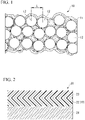
- Fig. 1 is a schematic cross-sectional diagram of an infrared shielding film according to one embodiment of the present invention.
- an infrared shielding film 10 is constituted of an organic binder 11, and a plurality of ITO particles 12 dispersed in the organic binder 11.
- the ITO particles 12 are mainly dispersed in the state of primary particles.
- the organic binder 11 is preferably an organic compound having a group having an affinity for the ITO particles 12.
- the organic binder 11 is preferably in contact with the ITO particles 12 via the group having an affinity.
- the ITO particles 12 are preferably coated with the organic binder 11. By being coated with the organic binder 11, the inter-particle distance of the ITO particles 12 is likely to be a constant space.
- the group having an affinity for the ITO particle 12 include a nitrile group (-CN) and an ester group (-CO-OR 1 ).
- R 1 of the ester group represents a hydrogen atom, an alkyl group having the number of carbon atoms in the range of 1 to 20, an aryl group having the number of carbon atoms in the range of 6 to 20, and an aralkyl group having the number of carbon atoms in the range of 7 to 20.
- the group having an affinity for the 1TO particles 12 is preferably a nitrile group.
- the organic binder 11 is preferably a hydrocarbon compound having a group having an affinity for the ITO particles 12 at the terminal.
- the hydrocarbon compound may be an unsaturated hydrocarbon compound or may be a saturated hydrocarbon compound.
- the hydrocarbon compound may be a chain hydrocarbon compound or may be a cyclic hydrocarbon compound.
- alkanes (C n H 2n+2 ), alkenes (C n H 2n ), and alkynes (C n H 2n-2 ) can be used.
- cyclic hydrocarbon compound cycloalkanes (C n H 2n ), cycloalkenes (C n H 2n-2 ), cycloalkynes (C n H 2n-4 ), and aromatic hydrocarbon compounds (benzene, naphthalene) can be used.
- the number of carbon atoms of the hydrocarbon compound is preferably in a range of 8 to 20.
- the hydrocarbon compound is preferably an alkane or an alkene.
- the boiling point of the organic binder 11 is preferably 120°C or higher.
- Examples of the organic binder 11 having a nitrile group include (Z)-4-octenenitrile, (Z)-5-octenenitrile, (Z)-5-nonenenitrile, (Z)-6-undecenitrile, (Z)-9-undecenenitrile, (Z)-9-octadecenenitrile, (Z)-9-decenenitrile, (Z)-9-decenenitrile, (Z)-11-dodecenenitrile, (Z)-2-tridecenitrile, (Z)-9-tetradecenitrile, (Z)-2-pentadecenenitrile, (E)-8-heptadecenitrile, (Z)-9-hexadecenenitrile, (Z)-11-nonadecenenitrile, (Z)-11-eicosenenitrile, octanenitrile, nonanenitrile, decanenitrile, undecan
- Examples of the organic binder 11 having an ester group include octanoic acid, octylic acid, nonanoic acid, decanoic acid, dodecanoic acid, tetradecanoic acid, palmitic acid, and stearic acid.
- the organic binder 11 one kind may be used alone, or two or more kinds may be used in combination.
- the ITO particles 12 are dispersed such that the average center-to-center distance between adjacent ITO particles is in the range of 9 nm or more and 36 nm or less. As shown in Fig. 1 , the average center-to-center distance is the average of a distance L between the center of an ITO particle 12 to be measured and the center of an ITO particle 12 located closest to the ITO particle 12.
- the distance L between the ITO particles can be measured using an enlarged photograph (an enlarged image of an observed image (such that 50 or more particles are contained in one visual field) of the cross-section of the infrared shielding film 10 using an electron scanning microscope (magnification: 200,000 to 400,000 times) of the cross-section of the infrared shielding film 10 (a cross-sectional photograph taken by using an ion milling device (IM4000PLUS or ArBlade 5000 (registered trademark) manufactured by Hitachi High-Tech Corporation)).
- the average distance L is the average distance between the ITO particles measured for the 50 ITO particles 12.
- a ratio Y/X of the average center-to-center distance Y between adjacent ITO particles to the average primary particle diameter X is in the range of 1.05 or more and 1.20 or less.
- the space between the ITO particles 12 becomes too narrow, the electric field of the surface plasmons is less likely to be enhanced, and there is a risk of a decrease of the infrared reflectance of the infrared shielding film 10.
- the roughness Ra of the surface of the infrared shielding film 10 tends to be too large.
- the space between the ITO particles 12 becomes too wide, the surface plasmons are less likely to be generated, and there is a risk of a decrease of the infrared reflectance of the infrared shielding film 10.
- the roughness Ra of the surface of the infrared shielding film 10 tends to be too small.
- the upper limit value of the above-mentioned ratio Y/X may be 1.15 or less.
- the average center-to-center distance between adjacent ITO particles may be 34.5 nm or less.
- the average primary particle diameter of the ITO particles 12 is preferably in a range of 8 nm or more and 30 nm or less. In a case where the average primary particle diameter of the ITO particles 12 is in the above-mentioned range, the dispersibility of the ITO particles 12 is high, which makes it possible to uniformly disperse the ITO particles 12 in the organic binder 11. Therefore, the infrared reflectance of the infrared shielding film 10 is further improved.
- the average primary particle diameter of the ITO particles 12 may be in the range of 10 nm or more and 25 nm or less.
- the average center-to-center distance between the ITO particles is preferably 10.5 nm or more and 30 nm or less.
- the roughness Ra of the film surface is in the range of 4 nm or more and 50 nm or less.
- the roughness Ra of the film surface is the average value of the roughness Ra of surfaces on both sides in a case where the infrared shielding film 10 is a free-standing film.
- the roughness Ra of the film surface is the roughness Ra of the film surface on the opposite side to the substrate side.
- the roughness Ra of the film surface can be reduced by reducing the amount of the ITO particles 12 on the film surface side of the infrared shielding film 10.
- the roughness Ra of the film surface is less than 4 nm, the amount of the ITO particles 12 is too small, the surface plasmons are less likely to be generated, and there is a risk of a decrease of the infrared reflectance of the infrared shielding film 10.
- the roughness Ra of the film surface exceeds 50 nm, the amount of the ITO particles 12 is too large, and there is a risk that the haze is likely to be generated.
- the roughness Ra of the film surface of the infrared shielding film 10 may be in the range of 5 nm or more and 40 nm or less.
- the roughness Ra of the film surface of the infrared shielding film 10 can be obtained by analyzing a cut surface image of the above-mentioned film using image analysis software, extracting a surface roughness line of the surface on the opposite side to a glass substrate of the film, performing image analysis on the obtained surface roughness line using image processing software, and calculating the sum of the average value of absolute values of the mountain height from the highest mountain peak to the fifth mountain of the surface roughness line, and the average value of absolute values of the fifth valley bottom from the lowest valley bottom.
- the content ratio of the organic binder 11 and the ITO particles 12 of the infrared shielding film 10 is not particularly limited, but it is preferable that the amount of the organic binder 11 be an amount in the range of 5 parts by mass or more and 30 parts by mass or less when the ITO particles 12 are 100 parts by mass.
- the infrared shielding film of the present embodiment can be deposited by preparing a coating liquid containing ITO particles with an organic binder, and then coating a substrate with the obtained coating liquid and drying it, for example.
- the ITO particles can be produced using a method of heating fatty acid salts of In and fatty acid salts of Sn in the presence of an organic solvent while stirring to cause the fatty acid salts of In and the fatty acid salts of Sn to react with each other, for example. Since the surface of the ITO particles, which are produced using the fatty acid salts of In and the fatty acid salts of Sn, is coated with an organic protective group derived from the fatty acid salts, it is difficult to form agglomerated particles. Therefore, an infrared shielding film in which the ITO particles are dispersed in the state of primary particles is easily obtained.
- the fatty acid of the fatty acid salts of In and the fatty acid salts of Sn is preferably a saturated fatty acid.
- the fatty acid is preferably a linear fatty acid or a branched fatty acid.
- the number of carbon atoms of the fatty acid is preferably in a range of 5 to 18.
- Examples of the fatty acid salts include hexanoic acid, octanoic acid, decanoic acid, palmitic acid, stearic acid, neodecanoic acid, and 2-ethylhexanoic acid.
- the fatty acid salts of In and the fatty acid salts of Sn may be salts of the same fatty acids or may be salts of different fatty acids.
- the organic solvent is preferably a hydrocarbon compound.
- the hydrocarbon compound may be an unsaturated hydrocarbon compound or may be a saturated hydrocarbon compound.
- the hydrocarbon compound may be a chain hydrocarbon compound or may be a cyclic hydrocarbon compound.
- the number of carbon atoms of the hydrocarbon compound is preferably in a range of 5 to 22.
- n-octyl ether, octadecene, n-trioctylamine, and dodecylamine can be used, for example.
- the temperature when heating the fatty acid salts of In and the fatty acid salts of Sn is in the range of 200°C or higher and 350°C or lower, for example.
- the heating time is in the range of 0.5 hours or more and 8 hours or less, for example.
- the ITO particles with the organic binder can be produced by mixing ITO particles and an organic binder in an organic solvent to generate the ITO particles with the organic binder, and then recovering the ITO particles with the organic binder in the organic solvent.
- the organic solvent is not particularly limited, but alcohols and ketones are preferably used.
- the alcohols include methanol, ethanol, 1-butanol, 2-butanol, hexanol, 2-propanol, ethylene glycol monoethyl ether, ethylene glycol monomethyl ether, methoxyethanol, propylene glycol, and diethylene glycol.
- the ketones include acetone, methyl ethyl ketone (MEK), and methyl isobutyl ketone (MIBK).
- MEK methyl ethyl ketone
- MIBK methyl isobutyl ketone
- the blending ratio of the amount of the organic binder and the ITO particles is a ratio such that the amount of the organic binder is in the range of 5 parts by mass or more and 30 parts by mass or less with respect to 100 parts by mass of the ITO particles. It is preferable to use the organic binder and the ITO particles with sufficient stirring.
- a known solid-liquid separation method such as decantation or filtration can be used.
- the coating liquid can be prepared by injecting the recovered ITO particles with the organic binder into an organic solvent for the coating liquid, and dispersing.
- organic solvent for the coating liquid alcohols, ketones, glycol ethers, glycol ether acetates, and hydrocarbon compounds can be used.
- Examples of the alcohols include methanol, ethanol, propanol, and isopropyl alcohol (IPA).
- Examples of the ketones include acetone, methyl ethyl ketone (MEK), and methyl isobutyl ketone (MIBK).
- Examples of the glycol ethers include ethylene glycol monomethyl ether, diethylene glycol monomethyl ether, propylene glycol monomethyl ether, dipropylene glycol monomethyl ether, ethylene glycol monoethyl ether, diethylene glycol monoethyl ether, propylene glycol monoethyl ether, and dipropylene glycol monoethyl ether.
- glycol ether acetates examples include ethylene glycol monomethyl ether acetate, diethylene glycol monomethyl ether acetate, propylene glycol monomethyl ether acetate, dipropylene glycol monomethyl ether acetate, ethylene glycol monoethyl ether acetate, diethylene glycol monoethyl ether acetate, propylene glycol monoethyl ether acetate, and dipropylene glycol monoethyl ether acetate.
- hydrocarbon compounds examples include cyclic hydrocarbon compounds such as benzene, toluene, ethylbenzene, p-xylene, cyclopropane, and cyclohexane, and chain hydrocarbon compounds such as n-pentane, n-hexane, n-heptane, n-octane, n-tetradecane, n-hexadecane, and n-octadecane.
- cyclic hydrocarbon compounds such as benzene, toluene, ethylbenzene, p-xylene, cyclopropane, and cyclohexane
- chain hydrocarbon compounds such as n-pentane, n-hexane, n-heptane, n-octane, n-tetradecane, n-hexadecane, and n-octadecane.
- the organic solvent is preferably a low-polarity organic solvent such as hydrocarbon compounds, or a mixed solvent containing a low-polarity organic solvent and a high-polarity organic solvent such as alcohols.
- the blending ratio of the low-polarity organic solvent and the high-polarity organic solvent is preferably in a range of the mass ratio of 99:1 to 90:10 (former:latter).
- the ITO particles are preferably dispersed in the organic solvent in the state of primary particles or close to the primary particles.
- the average particle diameter of the ITO particles in the coating liquid measured by a dynamic light scattering particle size analyzer is preferably 1.3 times or less and more preferably 1.2 times or less the average primary particle diameter of the ITO particles. In a case where the average particle diameter of the ITO particles in the coating liquid is too long, there is a risk that the roughness Ra of the film surface of the obtained infrared shielding film is too large.
- a general coating method such as a slot die coater, a spin coater, an applicator, and a bar coater can be used, for example.
- the drying temperature at the time of drying the coating liquid with which the substrate is coated may be any temperature as long as the organic solvent of the coating liquid volatilizes, and is in the range of 40°C or higher and 120°C or lower, for example.
- the drying time varies depending on the drying temperature, but is usually in the range of 5 minutes or more and 120 minutes or less.
- Fig. 2 is a schematic cross-sectional diagram of an infrared shielding material according to one embodiment of the present invention.
- an infrared shielding material 20 includes a substrate 21, an infrared shielding layer 22, and an overcoat layer 23.
- the overcoat layer 23 may be provided as needed, and is not necessarily required.
- Examples of the material of the substrate 21 include glass and glass substitute resin.
- Examples of the glass substitute resin include polycarbonate resin and acrylic resin.
- the shape of the substrate 21 is not particularly limited, and may be any shape such as a plate shape, a sheet shape, and a film shape.
- the infrared shielding layer 22 is a layer that reflects infrared rays.
- the infrared shielding layer 22 is the above-mentioned infrared shielding film 10.
- the overcoat layer 23 has a function of protecting the infrared shielding layer 22 to improve chemical resistance and abrasion resistance.
- glass or resin can be used, for example.
- resin a polycarbonate resin, an acrylic resin, an epoxy resin, and a polyvinyl acetal resin can be used.
- the thickness of the overcoat layer 23 is preferably in a range of 1 ⁇ m or more and 5 ⁇ m or less. When the thickness of the overcoat layer 23 is 1 ⁇ m or more, chemical resistance is improved. Meanwhile, when the thickness of the overcoat layer 23 is 5 ⁇ m or less, a decrease of the transmission rate of visible light is suppressed.
- the reflectance with respect to infrared rays is high since the ITO particles 12 are dispersed with spaces therebetween such that the average center-to-center distance between the adjacent ITO particles is in the range of 9 nm or more and 36 nm or less, and the ratio of the average center-to-center distance between the adjacent ITO particles to the average primary particle diameter of the ITO particles 12 is in the range of 1.05 or more and 1.20 or less.
- the roughness Ra of the film surface is 4 nm or more and a large number of the ITO particles 12 are dispersed in the vicinity of the film surface, the reflectance to infrared rays is high.
- the roughness Ra of the film surface is 50 nm or less, scattering of visible light on the film surface is less likely to occur, which makes the haze of the infrared shielding film 10 low.
- the infrared shielding film 10 of the present embodiment in a case where the average primary particle diameter of the ITO particles 12 in the range of 8 nm or more and 30 nm or less, which is fine, scattering of visible light is less likely to occur, which makes the haze of the infrared shielding film 10 lower.
- the reflectance of the infrared shielding film 10 with respect to infrared rays is further improved.
- the infrared shielding layer 22 is the above-mentioned infrared shielding film 10. Therefore, the infrared shielding material 20 of the present embodiment has low haze, and high reflectance with respect to infrared rays.
- Indium octanoate was prepared as an In source, and tin octanoate was prepared as an Sn source.
- Injection to a glass container was performed such that a blending amount was 9.0 parts by mass in terms of In amount for the indium octanoate, 1.0 part by mass in terms of Sn amount for the tin octanoate, and 90 parts by mass for 1 -octadecene, and mixing was performed.
- the obtained mixture was heated to 300°C in a nitrogen atmosphere with being stirred, and this temperature was maintained for 3 hours to generate ITO particles in which the particle surface was modified with an organic protective group.
- the generated ITO particles were recovered by decantation.
- the recovered ITO particles were cleaned several times using ethanol.
- the ITO particles after cleaning were dispersed in ethanol to form a slurry.
- (Z)-9-Octadecenenitrile as an organic binder was added to the obtained slurry in an amount of 5 parts by mass with respect to 100 parts by mass of the ITO particles in the slurry, and stirring was performed. Thereafter, ITO particles with (Z)-9-octadecenenitrile having the surface on which (Z)-9-octadecenenitrile was adsorbed were recovered by filtration.
- An organic solvent containing 1-butanol and toluene in the mass ratio of 5:95 (former:latter) was prepared.
- the ITO particles with (Z)-9-octadecenenitrile were dispersed in this organic solvent to obtain a coating liquid (dispersion liquid of the ITO particles with (Z)-9-octadecenenitrile).
- the concentration of solid contents in the coating liquid was 10% by mass.
- 0.2 mL of the obtained coating liquid was added dropwise onto a glass substrate (size: length 50 mm ⁇ width 50 mm ⁇ thickness 0.7 mm) to perform coating by spin coating under the condition of a rotation speed of 2000 rpm. Subsequently, the glass substrate was heated at 120°C and dried to deposit an ITO particle film on the glass substrate.
- a coating liquid was prepared in the same manner as in Present Invention Example 1 except that as the In source and Sn source, fatty acid salts described in Table 1 below were blended in blending ratios described in Table 1 below to produce ITO particles, and that as the organic binder, compounds described in Table 1 below were added in ratio amounts described in Table 1 below with respect to 100 parts by mass of the ITO particles. In Comparative Example 1, an organic binder was not used. Then, using the obtained coating liquid, an ITO particle film was deposited on a glass substrate in the same manner as in Present Invention Example 1.
- the ITO particle film was peeled off from the glass substrate.
- the peeled ITO particle film was injected to an organic solvent containing 1-butanol and toluene in the mass ratio of 5:95 (former:latter), and ultrasonic dispersion treatment was performed to disperse the ITO particles in the ITO particle film.
- the ITO particles dispersed in the solvent were recovered, and an enlarged image of the recovered ITO particles was taken using a transmission electron microscope.
- the obtained enlarged image was subjected to image analysis using image processing software (ImageJ) to measure the Feret diameters of 10,000 ITO particles, and the average value thereof was defined as the average primary particle diameter X of the ITO particles.
- ImageJ image processing software
- a resin-embedded ITO particle film was cut in a direction perpendicular to the film surface, and the cut surface was mirror-polished.
- the cut surface was imaged using an electron scanning microscope (SU8000 manufactured by Hitachi High-Technologies Corporation).
- SU8000 manufactured by Hitachi High-Technologies Corporation
- a surface roughness line of the surface on the opposite side to the glass substrate of the ITO particle film was extracted using image analysis software (Thermo Scientific, Avizo software). Image analysis was performed on the obtained surface roughness line using image processing software (ImageJ), and the sum of the average value of absolute values of the mountain height from the highest mountain peak to the fifth mountain of the surface roughness line, and the average value of absolute values of the fifth valley bottom from the lowest valley bottom was calculated and defined as the roughness Ra.
- Table 2 The results are shown in Table 2 below.
- the haze of the ITO particle film deposited on the glass substrate was measured according to a method specified in JIS K 7136:2000 (Plastics - Determination of Haze for Transparent Materials).
- a Haze Meter HZ-2 manufactured by Suga Test Instruments Co., Ltd. was used. The results are shown in Table 2 below.
- the surface of the ITO particle film deposited on the glass substrate was irradiated with infrared rays in the wavelength range of 800 to 2500 nm, and the maximum reflectance of these infrared rays was measured using a spectrophotometer (Hitachi High-Technologies Corporation, product name U-4100). The results are shown in Table 2 below.
- the ITO particle films of Present Invention Examples 1 to 10 in which the average center-to-center distance between the ITO particles was in the range of 9 nm or more and 36 nm or less, the ratio Y/X of the average center-to-center distance Y between adjacent ITO particles to the average primary particle diameter X of the ITO particles was in the range of 1.05 or more and 1.20 or less, and the roughness Ra of the film surface was in the range of 4 nm or more and 50 nm or less, are useful as infrared shielding films since the haze was 0.35% or less in the all present invention examples, which was low, and the infrared region maximum reflectance was 45% or more, which was high.
- the infrared region maximum reflectance was low in the ITO particle films of Comparative Examples 1 and 2 in which the average center-to-center distance between the ITO particles was in the range of the present invention but the ratio Y/X was less than 1.05. This is because the space between the ITO particles was too narrow, which made the electric field of the surface plasmons difficult to be enhanced.
- the ITO particle films of Comparative Examples 1 and 2 had high haze. This is because the roughness Ra of the film surface exceeded 50 nm.
- the infrared region maximum reflectance was lower in the ITO particle film of Comparative Example 3 in which the average center-to-center distance exceeded 36 nm, the ratio of Y/X exceeded 1.20 or less, and the roughness Ra of the film surface was less than 4 nm. This is because the space between the ITO particles was too wide, which made the surface plasmons difficult to be generated.
- the infrared shielding film and the infrared shielding material of the present invention can be advantageously applied to applications requiring high visible light transmittance and infrared shielding properties, such as window glass used in automobiles and buildings.
Landscapes
- Chemical & Material Sciences (AREA)
- Physics & Mathematics (AREA)
- Organic Chemistry (AREA)
- Optics & Photonics (AREA)
- General Physics & Mathematics (AREA)
- Engineering & Computer Science (AREA)
- Inorganic Chemistry (AREA)
- Materials Engineering (AREA)
- Health & Medical Sciences (AREA)
- Life Sciences & Earth Sciences (AREA)
- Wood Science & Technology (AREA)
- Medicinal Chemistry (AREA)
- Manufacturing & Machinery (AREA)
- Chemical Kinetics & Catalysis (AREA)
- Polymers & Plastics (AREA)
- Toxicology (AREA)
- Paints Or Removers (AREA)
- Laminated Bodies (AREA)
- Optical Filters (AREA)
- Vessels, Lead-In Wires, Accessory Apparatuses For Cathode-Ray Tubes (AREA)
- Ultra Sonic Daignosis Equipment (AREA)
Applications Claiming Priority (2)
| Application Number | Priority Date | Filing Date | Title |
|---|---|---|---|
| JP2020024160 | 2020-02-17 | ||
| PCT/JP2020/029291 WO2021166283A1 (ja) | 2020-02-17 | 2020-07-30 | 赤外線遮蔽膜及び赤外線遮蔽材 |
Publications (2)
| Publication Number | Publication Date |
|---|---|
| EP4089449A1 true EP4089449A1 (de) | 2022-11-16 |
| EP4089449A4 EP4089449A4 (de) | 2024-01-31 |
Family
ID=77391903
Family Applications (1)
| Application Number | Title | Priority Date | Filing Date |
|---|---|---|---|
| EP20920163.1A Withdrawn EP4089449A4 (de) | 2020-02-17 | 2020-07-30 | Infrarotabschirmender film und infrarotabschirmendes material |
Country Status (7)
| Country | Link |
|---|---|
| US (1) | US12174406B2 (de) |
| EP (1) | EP4089449A4 (de) |
| JP (1) | JP7364030B2 (de) |
| KR (1) | KR20220132547A (de) |
| CN (1) | CN115104047B (de) |
| TW (1) | TWI834906B (de) |
| WO (1) | WO2021166283A1 (de) |
Family Cites Families (56)
| Publication number | Priority date | Publication date | Assignee | Title |
|---|---|---|---|---|
| JP3250125B2 (ja) * | 1993-06-30 | 2002-01-28 | 三菱マテリアル株式会社 | 赤外線カットオフ粉末 |
| JPH0841441A (ja) * | 1994-05-25 | 1996-02-13 | Sumitomo Metal Mining Co Ltd | 紫外線、近赤外線遮へい用インジウム−錫酸化物粉末とこれを用いた紫外線、近赤外線遮へいガラスおよびその製造方法 |
| JP4600685B2 (ja) * | 1994-05-25 | 2010-12-15 | 住友金属鉱山株式会社 | 紫外線、近赤外線遮へいガラス |
| JPH09140275A (ja) | 1995-11-22 | 1997-06-03 | Kureha Chem Ind Co Ltd | 熱線吸収材 |
| JPH10265718A (ja) * | 1997-03-27 | 1998-10-06 | Mitsubishi Materials Corp | 防眩性赤外線遮断膜形成用塗料 |
| JP3787947B2 (ja) * | 1997-04-16 | 2006-06-21 | 三菱化学エムケーブイ株式会社 | 屋外展張用フィルム |
| JP2000000927A (ja) * | 1998-06-12 | 2000-01-07 | Tomoegawa Paper Co Ltd | 赤外線カットオフフィルム |
| JP2001332128A (ja) * | 2000-05-19 | 2001-11-30 | Tdk Corp | 機能性膜 |
| DE10160356A1 (de) * | 2001-12-08 | 2003-06-26 | Nanogate Technologies Gmbh | IR-Schutz |
| TWI274662B (en) * | 2002-03-29 | 2007-03-01 | Toray Industries | Laminated film, filter for display and display |
| CN100344709C (zh) * | 2003-03-17 | 2007-10-24 | 李海旭 | 用于隔离热射线的组合物,由此形成的膜以及形成该组合物和膜的方法 |
| JP4989219B2 (ja) * | 2004-03-31 | 2012-08-01 | 日本板硝子株式会社 | 赤外線カットガラス及びその製造方法 |
| JP2006010759A (ja) * | 2004-06-22 | 2006-01-12 | Sumitomo Metal Mining Co Ltd | 近赤外線遮蔽材料微粒子分散体および近赤外線遮蔽体並びに近赤外線遮蔽材料を通過する可視光の色調調整方法 |
| JP2006245516A (ja) * | 2005-03-07 | 2006-09-14 | Seiko Epson Corp | 成膜方法、電子デバイス用基板、電子デバイスおよび電子機器 |
| US20090002809A1 (en) * | 2006-01-16 | 2009-01-01 | Nippon Sheet Glass Company Limited | Glass Plate Having Thin Film Formed Thereon |
| US20070178317A1 (en) * | 2006-02-01 | 2007-08-02 | Asahi Glass Company, Limited | Infrared shielding film-coated glass plate and process for its production |
| JP4617499B2 (ja) * | 2006-03-31 | 2011-01-26 | Dowaエレクトロニクス株式会社 | Ito粉体およびその製造方法、透明導電材用塗料、並びに透明導電膜 |
| EP1842834A1 (de) | 2006-04-04 | 2007-10-10 | Asahi Glass Company, Limited | Mit Infrarotschutzfilm beschichtete Glasplatte und Herstellungsverfahren dafür |
| JP2007320780A (ja) * | 2006-05-30 | 2007-12-13 | Nippon Sheet Glass Co Ltd | 赤外線カット膜が形成された透明物品 |
| US7952805B2 (en) * | 2006-08-22 | 2011-05-31 | 3M Innovative Properties Company | Solar control film |
| KR100804003B1 (ko) * | 2006-09-08 | 2008-02-18 | 한국과학기술연구원 | 인듐주석산화물 막의 제조방법 |
| JP2009123396A (ja) * | 2007-11-12 | 2009-06-04 | Dowa Electronics Materials Co Ltd | Ito塗布液およびその製造方法 |
| EP2116513B1 (de) * | 2008-05-06 | 2017-07-05 | Evonik Degussa GmbH | Verfahren zur herstellung eines oberflächenmodifizierten agglomerates von indiumzinnoxid, das nach diesem verfahren erhältliche oberflächenmodifizierte agglomerat selbst, sowie eine beschichtungsmasse hiermit |
| JP2009288732A (ja) * | 2008-06-02 | 2009-12-10 | Asahi Kasei Corp | 防眩フィルム |
| CN100595141C (zh) * | 2008-06-06 | 2010-03-24 | 东华大学 | 一种铟锡氧化物组装碳纳米管复合材料的制备方法 |
| JP5726728B2 (ja) * | 2009-05-12 | 2015-06-03 | Dowaエレクトロニクス株式会社 | Ito粉体、ito塗料、並びに、ito塗料を用いて成膜される透明導電膜 |
| JP5564207B2 (ja) * | 2009-07-06 | 2014-07-30 | Dowaエレクトロニクス株式会社 | 赤外線遮蔽材料、赤外線遮蔽用塗料、赤外線遮蔽膜、並びに、赤外線遮蔽基材 |
| CN103221850B (zh) * | 2010-11-22 | 2015-05-13 | 富士胶片株式会社 | 热射线屏蔽材料 |
| JP5614270B2 (ja) * | 2010-12-16 | 2014-10-29 | コニカミノルタ株式会社 | 熱線遮断フィルムとその製造方法 |
| CN102653862A (zh) * | 2011-03-01 | 2012-09-05 | 国家纳米科学中心 | 一种氧化铟锡纳米涂层的制备方法 |
| JP2012189683A (ja) * | 2011-03-09 | 2012-10-04 | Nitto Denko Corp | 赤外線反射フィルム |
| JP5709707B2 (ja) * | 2011-03-25 | 2015-04-30 | 富士フイルム株式会社 | 熱線遮蔽材 |
| JP5699738B2 (ja) * | 2011-03-29 | 2015-04-15 | コニカミノルタ株式会社 | ハードコートフィルムと、それを用いた熱線遮断フィルム及び有機素子デバイス |
| WO2012157655A1 (ja) * | 2011-05-17 | 2012-11-22 | 富士フイルム株式会社 | 熱線遮蔽材、貼合せ構造体及び合わせガラス |
| WO2013077252A1 (ja) * | 2011-11-21 | 2013-05-30 | コニカミノルタ株式会社 | 赤外遮蔽フィルムおよび赤外遮蔽体 |
| EP2833173A4 (de) * | 2012-03-29 | 2015-11-25 | Fujifilm Corp | Hitzestrahlenabschirmungsmaterial und laminierte struktur |
| JPWO2014010562A1 (ja) * | 2012-07-13 | 2016-06-23 | コニカミノルタ株式会社 | 赤外遮蔽フィルム |
| JP5849899B2 (ja) * | 2012-08-27 | 2016-02-03 | 旭硝子株式会社 | 近赤外線吸収フィルタおよび固体撮像装置 |
| JP2014080466A (ja) * | 2012-10-15 | 2014-05-08 | Mitsubishi Materials Corp | 熱線遮蔽組成物 |
| EP2910985B1 (de) | 2012-10-19 | 2019-05-08 | Nippon Kayaku Kabushiki Kaisha | Wärmestrahlenabschirmende folie |
| JP5528645B1 (ja) | 2012-11-27 | 2014-06-25 | 東レフィルム加工株式会社 | ハードコートフィルムおよび透明導電性フィルム |
| JP6443329B2 (ja) * | 2013-04-10 | 2018-12-26 | Agc株式会社 | 赤外線遮蔽フィルタおよび撮像装置 |
| KR102024647B1 (ko) * | 2013-05-08 | 2019-09-24 | 엘지디스플레이 주식회사 | 무기 리간드를 갖는 용액형 ito 및 그 제조 방법 |
| US9908306B2 (en) * | 2013-05-16 | 2018-03-06 | Nippon Kayaku Kabushikikaisha | Infrared shielding sheet, method for manufacturing the same, and use of the same |
| JP6301483B2 (ja) | 2014-08-27 | 2018-03-28 | 富士フイルム株式会社 | 断熱フィルム、断熱フィルムの製造方法、断熱ガラスおよび窓 |
| JP6492625B2 (ja) * | 2014-12-22 | 2019-04-03 | 三菱マテリアル株式会社 | 赤外線遮蔽積層体及びこれを用いた赤外線遮蔽材 |
| US10330837B2 (en) | 2015-03-31 | 2019-06-25 | Konica Minolta, Inc. | Near-infrared shielding film, method for producing the same, and pressure-sensitive adhesive composition |
| JP2017170386A (ja) * | 2016-03-25 | 2017-09-28 | 阪本薬品工業株式会社 | 金属酸化物微粒子の水系分散剤、及びそれを含有する分散体 |
| US10906097B2 (en) * | 2016-06-02 | 2021-02-02 | M. Technique Co., Ltd. | Ultraviolet and/or near-infrared blocking agent composition for transparent material |
| JP6654515B2 (ja) * | 2016-06-15 | 2020-02-26 | 日本化薬株式会社 | 赤外線遮蔽シート、赤外線遮蔽合わせガラス用中間膜並びに赤外線遮蔽合わせガラス及びその製造方法 |
| JP6747324B2 (ja) * | 2017-02-06 | 2020-08-26 | 三菱マテリアル株式会社 | 金属酸化物微粒子の製造方法 |
| JP2019066839A (ja) * | 2017-09-28 | 2019-04-25 | 三菱マテリアル株式会社 | 赤外線遮蔽膜形成用液組成物及びこれを用いた赤外線遮蔽膜の製造方法及び赤外線遮蔽膜 |
| WO2019065788A1 (ja) * | 2017-09-28 | 2019-04-04 | 三菱マテリアル株式会社 | 赤外線遮蔽膜形成用液組成物及びこれを用いた赤外線遮蔽膜の製造方法並びに赤外線遮蔽膜 |
| JP6933156B2 (ja) * | 2018-02-14 | 2021-09-08 | 三菱マテリアル株式会社 | 金属酸化物分散液の製造方法 |
| JP7020223B2 (ja) * | 2018-03-22 | 2022-02-16 | 三菱マテリアル株式会社 | 金属酸化物微粒子とその製造方法、赤外線遮蔽膜形成用分散液とその製造方法、赤外線遮蔽膜の形成方法並びに赤外線遮蔽膜付き基材 |
| JP2020024160A (ja) | 2018-08-08 | 2020-02-13 | 株式会社ミツトヨ | 計測器特定装置及びプログラム |
-
2020
- 2020-07-30 US US17/798,150 patent/US12174406B2/en active Active
- 2020-07-30 WO PCT/JP2020/029291 patent/WO2021166283A1/ja not_active Ceased
- 2020-07-30 CN CN202080096657.6A patent/CN115104047B/zh active Active
- 2020-07-30 JP JP2022501608A patent/JP7364030B2/ja active Active
- 2020-07-30 KR KR1020227026544A patent/KR20220132547A/ko active Pending
- 2020-07-30 EP EP20920163.1A patent/EP4089449A4/de not_active Withdrawn
- 2020-07-31 TW TW109125941A patent/TWI834906B/zh active
Also Published As
| Publication number | Publication date |
|---|---|
| KR20220132547A (ko) | 2022-09-30 |
| US12174406B2 (en) | 2024-12-24 |
| CN115104047A (zh) | 2022-09-23 |
| WO2021166283A1 (ja) | 2021-08-26 |
| EP4089449A4 (de) | 2024-01-31 |
| CN115104047B (zh) | 2024-06-07 |
| TW202132526A (zh) | 2021-09-01 |
| TWI834906B (zh) | 2024-03-11 |
| JP7364030B2 (ja) | 2023-10-18 |
| US20230081640A1 (en) | 2023-03-16 |
| JPWO2021166283A1 (de) | 2021-08-26 |
Similar Documents
| Publication | Publication Date | Title |
|---|---|---|
| EP1836128B1 (de) | Zirconiumoxidteilchen | |
| KR101398506B1 (ko) | 구상 코어셸형 산화세륨/고분자 하이브리드 나노입자의 집적체 및 그 제조 방법 | |
| US9273073B2 (en) | Tin dioxide nanopartcles and method for making the same | |
| Ali et al. | The structure analysis and optical performance of PVA films doped with Fe3+-metal for UV-limiter, and optoelectronics | |
| WO2014158466A1 (en) | Stabilization agents for silver nanowire based transparent conductive films | |
| JP2010254889A (ja) | 金属酸化物微粒子分散体及びその製造方法 | |
| WO2016091104A1 (en) | Electrically conductive compositions, process and applications | |
| EP4089449A1 (de) | Infrarotabschirmender film und infrarotabschirmendes material | |
| Chang et al. | Preparation of HMDS-modified silica/polyacrylate hydrophobic hard coatings on PMMA substrates | |
| JP2008169233A (ja) | ナノ粒子分散液の製造方法、ナノ粒子分散液、ナノコンポジット材の製造方法、ナノコンポジット材及び透明容器又は透明フィルム | |
| JP6136623B2 (ja) | 透明導電膜用塗工液及びこれを用いた透明導電膜 | |
| TWI814742B (zh) | 紅外線遮蔽膜形成用液組成物及使用其之紅外線遮蔽膜之製造方法及紅外線遮蔽膜 | |
| JP2022033609A (ja) | 金属酸化物ナノ粒子、金属酸化物ナノ粒子を含む組成物及びその硬化物 | |
| CN114656818B (zh) | 金属氧化物分散液 | |
| EP3730232A1 (de) | Silberpulver für tinte oder farbe | |
| JP2005305367A (ja) | 粒子分散体およびその用途 | |
| KR102716656B1 (ko) | 금속 산화물 분산액, 디스플레이용 필름 조성물 및 디스플레이용 광학 부재 | |
| TWI863909B (zh) | 紅外線吸收透明基材 | |
| EP3362511B1 (de) | Anorganische/organische hybride optische folien mit lösungsbearbeitbarer hri | |
| KR20040085078A (ko) | 저융점 카복실산 주석염 및 이의 제조방법 | |
| JP5087783B2 (ja) | 表面被覆六ホウ化物粒子前駆体の製造方法と表面被覆六ホウ化物粒子前駆体、表面被覆六ホウ化物粒子並びにその分散体、および、表面被覆六ホウ化物粒子が用いられた構造体と物品 | |
| JP2004091763A (ja) | 膜形成剤および膜 | |
| EP1957691A2 (de) | Silikatumhüllte teilchen in einer metallschicht | |
| TWI918958B (zh) | 紅外線吸收複合微粒子、紅外線吸收微粒子分散液及紅外線吸收微粒子分散體 | |
| JP2022524417A (ja) | 組成物 |
Legal Events
| Date | Code | Title | Description |
|---|---|---|---|
| STAA | Information on the status of an ep patent application or granted ep patent |
Free format text: STATUS: THE INTERNATIONAL PUBLICATION HAS BEEN MADE |
|
| PUAI | Public reference made under article 153(3) epc to a published international application that has entered the european phase |
Free format text: ORIGINAL CODE: 0009012 |
|
| STAA | Information on the status of an ep patent application or granted ep patent |
Free format text: STATUS: REQUEST FOR EXAMINATION WAS MADE |
|
| 17P | Request for examination filed |
Effective date: 20220808 |
|
| AK | Designated contracting states |
Kind code of ref document: A1 Designated state(s): AL AT BE BG CH CY CZ DE DK EE ES FI FR GB GR HR HU IE IS IT LI LT LU LV MC MK MT NL NO PL PT RO RS SE SI SK SM TR |
|
| DAV | Request for validation of the european patent (deleted) | ||
| DAX | Request for extension of the european patent (deleted) | ||
| A4 | Supplementary search report drawn up and despatched |
Effective date: 20240105 |
|
| RIC1 | Information provided on ipc code assigned before grant |
Ipc: G01G 19/00 20060101ALI20231225BHEP Ipc: G02B 5/20 20060101ALI20231225BHEP Ipc: C09D 7/61 20180101ALI20231225BHEP Ipc: C09D 5/32 20060101ALI20231225BHEP Ipc: C08K 3/22 20060101ALI20231225BHEP Ipc: G02B 5/26 20060101AFI20231225BHEP |
|
| GRAP | Despatch of communication of intention to grant a patent |
Free format text: ORIGINAL CODE: EPIDOSNIGR1 |
|
| STAA | Information on the status of an ep patent application or granted ep patent |
Free format text: STATUS: GRANT OF PATENT IS INTENDED |
|
| INTG | Intention to grant announced |
Effective date: 20250123 |
|
| STAA | Information on the status of an ep patent application or granted ep patent |
Free format text: STATUS: THE APPLICATION IS DEEMED TO BE WITHDRAWN |
|
| 18D | Application deemed to be withdrawn |
Effective date: 20250524 |