EP3973910A1 - Software-center und robotersysteme mit hoher konfigurierbarkeit für chirurgische und andere verwendungen - Google Patents
Software-center und robotersysteme mit hoher konfigurierbarkeit für chirurgische und andere verwendungen Download PDFInfo
- Publication number
- EP3973910A1 EP3973910A1 EP21199257.3A EP21199257A EP3973910A1 EP 3973910 A1 EP3973910 A1 EP 3973910A1 EP 21199257 A EP21199257 A EP 21199257A EP 3973910 A1 EP3973910 A1 EP 3973910A1
- Authority
- EP
- European Patent Office
- Prior art keywords
- manipulator
- joint
- processor
- instrument
- end effector
- Prior art date
- Legal status (The legal status is an assumption and is not a legal conclusion. Google has not performed a legal analysis and makes no representation as to the accuracy of the status listed.)
- Pending
Links
- 238000001356 surgical procedure Methods 0.000 title description 24
- 230000033001 locomotion Effects 0.000 claims abstract description 345
- 238000000034 method Methods 0.000 claims abstract description 73
- 230000004044 response Effects 0.000 claims description 84
- 230000008878 coupling Effects 0.000 claims description 18
- 238000010168 coupling process Methods 0.000 claims description 18
- 238000005859 coupling reaction Methods 0.000 claims description 18
- 230000005484 gravity Effects 0.000 claims description 4
- 239000012636 effector Substances 0.000 abstract description 233
- 210000001503 joint Anatomy 0.000 description 142
- 239000013598 vector Substances 0.000 description 82
- 230000000694 effects Effects 0.000 description 41
- 230000001419 dependent effect Effects 0.000 description 31
- 239000011159 matrix material Substances 0.000 description 31
- 238000004364 calculation method Methods 0.000 description 29
- 230000003190 augmentative effect Effects 0.000 description 23
- 230000000712 assembly Effects 0.000 description 22
- 238000000429 assembly Methods 0.000 description 22
- 230000006870 function Effects 0.000 description 22
- 230000008901 benefit Effects 0.000 description 14
- 238000005457 optimization Methods 0.000 description 14
- 230000008859 change Effects 0.000 description 12
- 230000002401 inhibitory effect Effects 0.000 description 11
- 230000029058 respiratory gaseous exchange Effects 0.000 description 10
- 238000013459 approach Methods 0.000 description 9
- 238000010586 diagram Methods 0.000 description 9
- 238000001914 filtration Methods 0.000 description 9
- 238000013507 mapping Methods 0.000 description 9
- 230000007246 mechanism Effects 0.000 description 9
- 238000012545 processing Methods 0.000 description 9
- 238000003780 insertion Methods 0.000 description 8
- 230000037431 insertion Effects 0.000 description 8
- 210000000707 wrist Anatomy 0.000 description 8
- 230000003416 augmentation Effects 0.000 description 7
- 238000005259 measurement Methods 0.000 description 7
- 230000003044 adaptive effect Effects 0.000 description 6
- 238000013461 design Methods 0.000 description 6
- 230000009471 action Effects 0.000 description 5
- 230000008569 process Effects 0.000 description 5
- 230000009466 transformation Effects 0.000 description 5
- 230000006378 damage Effects 0.000 description 4
- 208000014674 injury Diseases 0.000 description 4
- 230000003993 interaction Effects 0.000 description 4
- 238000012986 modification Methods 0.000 description 4
- 230000004048 modification Effects 0.000 description 4
- 208000027418 Wounds and injury Diseases 0.000 description 3
- 238000004891 communication Methods 0.000 description 3
- 238000009826 distribution Methods 0.000 description 3
- 230000000670 limiting effect Effects 0.000 description 3
- 238000002324 minimally invasive surgery Methods 0.000 description 3
- 230000036961 partial effect Effects 0.000 description 3
- 230000002829 reductive effect Effects 0.000 description 3
- 238000002432 robotic surgery Methods 0.000 description 3
- 210000003815 abdominal wall Anatomy 0.000 description 2
- 238000003491 array Methods 0.000 description 2
- 238000010009 beating Methods 0.000 description 2
- 230000009286 beneficial effect Effects 0.000 description 2
- 238000006243 chemical reaction Methods 0.000 description 2
- 238000000354 decomposition reaction Methods 0.000 description 2
- 238000001514 detection method Methods 0.000 description 2
- 210000002310 elbow joint Anatomy 0.000 description 2
- 210000000245 forearm Anatomy 0.000 description 2
- 239000012456 homogeneous solution Substances 0.000 description 2
- 230000006872 improvement Effects 0.000 description 2
- 230000007935 neutral effect Effects 0.000 description 2
- 238000005096 rolling process Methods 0.000 description 2
- 239000000523 sample Substances 0.000 description 2
- 238000000926 separation method Methods 0.000 description 2
- 210000003857 wrist joint Anatomy 0.000 description 2
- 101100087530 Caenorhabditis elegans rom-1 gene Proteins 0.000 description 1
- 101100305983 Mus musculus Rom1 gene Proteins 0.000 description 1
- 230000001133 acceleration Effects 0.000 description 1
- 230000006978 adaptation Effects 0.000 description 1
- 239000000654 additive Substances 0.000 description 1
- 230000000996 additive effect Effects 0.000 description 1
- 238000004458 analytical method Methods 0.000 description 1
- 210000003484 anatomy Anatomy 0.000 description 1
- 238000013476 bayesian approach Methods 0.000 description 1
- 238000013398 bayesian method Methods 0.000 description 1
- 230000006399 behavior Effects 0.000 description 1
- 230000005540 biological transmission Effects 0.000 description 1
- 238000000205 computational method Methods 0.000 description 1
- 230000001143 conditioned effect Effects 0.000 description 1
- 230000003750 conditioning effect Effects 0.000 description 1
- 239000004020 conductor Substances 0.000 description 1
- 235000009508 confectionery Nutrition 0.000 description 1
- 230000007423 decrease Effects 0.000 description 1
- 230000002939 deleterious effect Effects 0.000 description 1
- 238000011161 development Methods 0.000 description 1
- 238000002405 diagnostic procedure Methods 0.000 description 1
- 238000005516 engineering process Methods 0.000 description 1
- 238000009472 formulation Methods 0.000 description 1
- 210000004247 hand Anatomy 0.000 description 1
- 238000003384 imaging method Methods 0.000 description 1
- 230000003601 intercostal effect Effects 0.000 description 1
- 238000012978 minimally invasive surgical procedure Methods 0.000 description 1
- 239000000203 mixture Substances 0.000 description 1
- 230000003287 optical effect Effects 0.000 description 1
- 239000013307 optical fiber Substances 0.000 description 1
- 230000001766 physiological effect Effects 0.000 description 1
- 238000002360 preparation method Methods 0.000 description 1
- 238000011084 recovery Methods 0.000 description 1
- 238000011160 research Methods 0.000 description 1
- 230000000284 resting effect Effects 0.000 description 1
- 230000000630 rising effect Effects 0.000 description 1
- 210000000115 thoracic cavity Anatomy 0.000 description 1
- 238000012549 training Methods 0.000 description 1
- 238000000844 transformation Methods 0.000 description 1
- 238000013519 translation Methods 0.000 description 1
- 230000008733 trauma Effects 0.000 description 1
Images


Classifications
-
- A—HUMAN NECESSITIES
- A61—MEDICAL OR VETERINARY SCIENCE; HYGIENE
- A61B—DIAGNOSIS; SURGERY; IDENTIFICATION
- A61B34/00—Computer-aided surgery; Manipulators or robots specially adapted for use in surgery
- A61B34/30—Surgical robots
- A61B34/35—Surgical robots for telesurgery
-
- B—PERFORMING OPERATIONS; TRANSPORTING
- B25—HAND TOOLS; PORTABLE POWER-DRIVEN TOOLS; MANIPULATORS
- B25J—MANIPULATORS; CHAMBERS PROVIDED WITH MANIPULATION DEVICES
- B25J9/00—Programme-controlled manipulators
- B25J9/16—Programme controls
-
- A—HUMAN NECESSITIES
- A61—MEDICAL OR VETERINARY SCIENCE; HYGIENE
- A61B—DIAGNOSIS; SURGERY; IDENTIFICATION
- A61B34/00—Computer-aided surgery; Manipulators or robots specially adapted for use in surgery
- A61B34/30—Surgical robots
-
- A—HUMAN NECESSITIES
- A61—MEDICAL OR VETERINARY SCIENCE; HYGIENE
- A61B—DIAGNOSIS; SURGERY; IDENTIFICATION
- A61B34/00—Computer-aided surgery; Manipulators or robots specially adapted for use in surgery
- A61B34/30—Surgical robots
- A61B34/37—Master-slave robots
-
- A—HUMAN NECESSITIES
- A61—MEDICAL OR VETERINARY SCIENCE; HYGIENE
- A61B—DIAGNOSIS; SURGERY; IDENTIFICATION
- A61B34/00—Computer-aided surgery; Manipulators or robots specially adapted for use in surgery
- A61B34/70—Manipulators specially adapted for use in surgery
- A61B34/71—Manipulators operated by drive cable mechanisms
-
- A—HUMAN NECESSITIES
- A61—MEDICAL OR VETERINARY SCIENCE; HYGIENE
- A61B—DIAGNOSIS; SURGERY; IDENTIFICATION
- A61B34/00—Computer-aided surgery; Manipulators or robots specially adapted for use in surgery
- A61B34/70—Manipulators specially adapted for use in surgery
- A61B34/77—Manipulators with motion or force scaling
-
- A—HUMAN NECESSITIES
- A61—MEDICAL OR VETERINARY SCIENCE; HYGIENE
- A61B—DIAGNOSIS; SURGERY; IDENTIFICATION
- A61B90/00—Instruments, implements or accessories specially adapted for surgery or diagnosis and not covered by any of the groups A61B1/00 - A61B50/00, e.g. for luxation treatment or for protecting wound edges
- A61B90/36—Image-producing devices or illumination devices not otherwise provided for
- A61B90/37—Surgical systems with images on a monitor during operation
-
- B—PERFORMING OPERATIONS; TRANSPORTING
- B25—HAND TOOLS; PORTABLE POWER-DRIVEN TOOLS; MANIPULATORS
- B25J—MANIPULATORS; CHAMBERS PROVIDED WITH MANIPULATION DEVICES
- B25J3/00—Manipulators of master-slave type, i.e. both controlling unit and controlled unit perform corresponding spatial movements
-
- B—PERFORMING OPERATIONS; TRANSPORTING
- B25—HAND TOOLS; PORTABLE POWER-DRIVEN TOOLS; MANIPULATORS
- B25J—MANIPULATORS; CHAMBERS PROVIDED WITH MANIPULATION DEVICES
- B25J9/00—Programme-controlled manipulators
- B25J9/16—Programme controls
- B25J9/1679—Programme controls characterised by the tasks executed
- B25J9/1682—Dual arm manipulator; Coordination of several manipulators
-
- B—PERFORMING OPERATIONS; TRANSPORTING
- B25—HAND TOOLS; PORTABLE POWER-DRIVEN TOOLS; MANIPULATORS
- B25J—MANIPULATORS; CHAMBERS PROVIDED WITH MANIPULATION DEVICES
- B25J9/00—Programme-controlled manipulators
- B25J9/16—Programme controls
- B25J9/1679—Programme controls characterised by the tasks executed
- B25J9/1689—Teleoperation
-
- A—HUMAN NECESSITIES
- A61—MEDICAL OR VETERINARY SCIENCE; HYGIENE
- A61B—DIAGNOSIS; SURGERY; IDENTIFICATION
- A61B34/00—Computer-aided surgery; Manipulators or robots specially adapted for use in surgery
- A61B34/30—Surgical robots
- A61B2034/301—Surgical robots for introducing or steering flexible instruments inserted into the body, e.g. catheters or endoscopes
-
- A—HUMAN NECESSITIES
- A61—MEDICAL OR VETERINARY SCIENCE; HYGIENE
- A61B—DIAGNOSIS; SURGERY; IDENTIFICATION
- A61B34/00—Computer-aided surgery; Manipulators or robots specially adapted for use in surgery
- A61B34/30—Surgical robots
- A61B2034/302—Surgical robots specifically adapted for manipulations within body cavities, e.g. within abdominal or thoracic cavities
-
- A—HUMAN NECESSITIES
- A61—MEDICAL OR VETERINARY SCIENCE; HYGIENE
- A61B—DIAGNOSIS; SURGERY; IDENTIFICATION
- A61B34/00—Computer-aided surgery; Manipulators or robots specially adapted for use in surgery
- A61B34/30—Surgical robots
- A61B2034/305—Details of wrist mechanisms at distal ends of robotic arms
-
- A—HUMAN NECESSITIES
- A61—MEDICAL OR VETERINARY SCIENCE; HYGIENE
- A61B—DIAGNOSIS; SURGERY; IDENTIFICATION
- A61B90/00—Instruments, implements or accessories specially adapted for surgery or diagnosis and not covered by any of the groups A61B1/00 - A61B50/00, e.g. for luxation treatment or for protecting wound edges
- A61B90/06—Measuring instruments not otherwise provided for
- A61B2090/064—Measuring instruments not otherwise provided for for measuring force, pressure or mechanical tension
- A61B2090/065—Measuring instruments not otherwise provided for for measuring force, pressure or mechanical tension for measuring contact or contact pressure
-
- A—HUMAN NECESSITIES
- A61—MEDICAL OR VETERINARY SCIENCE; HYGIENE
- A61B—DIAGNOSIS; SURGERY; IDENTIFICATION
- A61B90/00—Instruments, implements or accessories specially adapted for surgery or diagnosis and not covered by any of the groups A61B1/00 - A61B50/00, e.g. for luxation treatment or for protecting wound edges
- A61B90/36—Image-producing devices or illumination devices not otherwise provided for
- A61B90/361—Image-producing devices, e.g. surgical cameras
-
- G—PHYSICS
- G05—CONTROLLING; REGULATING
- G05B—CONTROL OR REGULATING SYSTEMS IN GENERAL; FUNCTIONAL ELEMENTS OF SUCH SYSTEMS; MONITORING OR TESTING ARRANGEMENTS FOR SUCH SYSTEMS OR ELEMENTS
- G05B2219/00—Program-control systems
- G05B2219/30—Nc systems
- G05B2219/39—Robotics, robotics to robotics hand
- G05B2219/39135—For multiple manipulators operating at same time, avoid collision
-
- G—PHYSICS
- G05—CONTROLLING; REGULATING
- G05B—CONTROL OR REGULATING SYSTEMS IN GENERAL; FUNCTIONAL ELEMENTS OF SUCH SYSTEMS; MONITORING OR TESTING ARRANGEMENTS FOR SUCH SYSTEMS OR ELEMENTS
- G05B2219/00—Program-control systems
- G05B2219/30—Nc systems
- G05B2219/39—Robotics, robotics to robotics hand
- G05B2219/39212—Select between autonomous or teleoperation control
-
- G—PHYSICS
- G05—CONTROLLING; REGULATING
- G05B—CONTROL OR REGULATING SYSTEMS IN GENERAL; FUNCTIONAL ELEMENTS OF SUCH SYSTEMS; MONITORING OR TESTING ARRANGEMENTS FOR SUCH SYSTEMS OR ELEMENTS
- G05B2219/00—Program-control systems
- G05B2219/30—Nc systems
- G05B2219/39—Robotics, robotics to robotics hand
- G05B2219/39322—Force and position control
-
- G—PHYSICS
- G05—CONTROLLING; REGULATING
- G05B—CONTROL OR REGULATING SYSTEMS IN GENERAL; FUNCTIONAL ELEMENTS OF SUCH SYSTEMS; MONITORING OR TESTING ARRANGEMENTS FOR SUCH SYSTEMS OR ELEMENTS
- G05B2219/00—Program-control systems
- G05B2219/30—Nc systems
- G05B2219/40—Robotics, robotics mapping to robotics vision
- G05B2219/40184—Compliant teleoperation, operator controls motion, system controls contact, force
-
- G—PHYSICS
- G05—CONTROLLING; REGULATING
- G05B—CONTROL OR REGULATING SYSTEMS IN GENERAL; FUNCTIONAL ELEMENTS OF SUCH SYSTEMS; MONITORING OR TESTING ARRANGEMENTS FOR SUCH SYSTEMS OR ELEMENTS
- G05B2219/00—Program-control systems
- G05B2219/30—Nc systems
- G05B2219/45—Nc applications
- G05B2219/45117—Medical, radio surgery manipulator
Definitions
- the present invention is generally related to medical, telesurgical, telepresence, telerobotic, and/or robotic devices, systems, and methods.
- the invention provides a surgical robotic system with sufficient degrees of freedom to provide both a desired movement within an internal surgical site and pivotal motion about a minimally invasive surgical aperture.
- the invention also provides systems, methods, and devices that can be used for the set-up and/or control of robotic systems.
- Minimally invasive medical techniques are intended to reduce the amount of tissue that is damaged during diagnostic or surgical procedures. Minimally invasive surgery can reduce patient recovery time, discomfort, and many of the deleterious side effects of surgery. While many of the surgeries performed each year in the US could potentially be performed in a minimally invasive manner, only a limited portion of current surgeries use these advantageous techniques due in part to limitations in existing minimally invasive surgical instruments and the challenges of mastering their use.
- Minimally invasive robotic systems have recently been developed to increase a surgeon's dexterity and avoid some of the limitations of traditional minimally invasive surgery.
- robotic surgery the surgeon uses some form of robotic control (such as a master-slave servomechanism or the like) to manipulate surgical instruments, rather than directly holding and moving the instruments by hand.
- the surgeon can view with an image of an internal surgical site to help the surgeon direct the treatment of tissues.
- the surgeon While viewing a two or three dimensional image on a display, the surgeon performs the surgical procedures on the patient by manipulating master control input devices, which in turn control the motion of robotic instruments.
- the robotic surgical instruments can be inserted through small, minimally invasive surgical apertures to treat tissues at surgical sites within the patient, often the trauma associated with accessing for open surgery.
- robotic systems can move the working ends of the surgical instruments with sufficient dexterity to perform quite intricate surgical tasks, often by pivoting shafts of the instruments at the minimally invasive aperture, sliding of the shaft axially through the aperture, rotating of the shaft within the aperture, and/or the like.
- the servomechanism used for telesurgery will often accept input from two master controllers (one for each of the surgeon's hands) and may include two or more robotic arms or manipulators. Mapping of the hand movements to the image of the robotic instruments displayed by the image capture device can help provide the surgeon with accurate control over the instruments associated with each hand. In many surgical robotic systems, one or more additional robotic manipulators are included for moving an endoscope or other image capture device, additional surgical instruments, or the like.
- robotic surgical manipulators may exhibit a significant amount of movement outside the patient, particularly when pivoting instruments about minimally invasive apertures. As the instruments may independently pivot about their associated apertures at the same time, the robotic manipulators disposed outside the patient may sometimes collide with each other (or with other structures or personnel). Additionally, set-up of the surgical robotic system in preparation for surgery can be challenging, and re-configuring the system to access different tissues of the patient during different phases of a procedure can be inconvenient.
- the present invention generally provides improved robotic and/or surgical devices, systems, and methods.
- the invention will employ highly configurable surgical robotic manipulators. These manipulators, for example, may have more degrees of freedom of movement than the associated surgical end effectors have within a surgical workspace.
- the present invention will often include a processor configured by software instructions to calculate a motion of the robotic linkage that includes pivoting a shaft of the manipulator linkage about an aperture site hence the notion of software centering.
- the joints of the robotic manipulators supporting the end effectors can allow the manipulator to move throughout a range of different configurations for a given end effector position, in some cases even when constraining lateral movement of the shaft from the aperture site so as to avoid injury to the adjacent tissues.
- the processor can take advantage of such manipulators to drive the manipulators to configurations which inhibit collisions involving one or more moving robotic structures.
- Set-up of such highly configurable robotic manipulators can be facilitated by processors which drive one or more joints of the manipulators while the manipulator is being positioned manually by the system operator (or by some other external interaction), with the joints optionally being driven in response to movements of other joints along the kinematic chain of the manipulator.
- Embodiments can adjust a center of pivotal motion of the manipulator in response to patient breathing and/or movement, in some cases by sensing forces applied between the manipulator and the tissues along the aperture site.
- Refined robotic structures for use in minimally invasive surgical applications and other applications are also provided, along with related robotic methods.
- a redundant degrees of freedom (RDOF) surgical robotic system with manipulate input comprises a manipulator assembly, an input device, and a processor.
- the manipulator assembly manipulates a distal end effector relative to a proximal base.
- the manipulator has a plurality of joints providing sufficient degrees of freedom to allow a range of joint states for an end effector position.
- the processor couples the input device to the manipulator assembly and may be configured to operate in different modes.
- the processor determines movements of the joints in response to the command so as to move the end effector with the desired movement.
- the processor drives at least one of the joints in response to an external articulation of another joint of the manipulator assembly.
- the clutch mode may be a pose clutch mode, an instrument clutch mode, or a port clutch mode.
- a RDOF software centering surgical robotic system comprises a processor, an input device, a manipulator, and a surgical instrument.
- the surgical instrument has a proximal end, a distal end effector suitable for insertion into a patient, and an intermediate portion therebetween.
- the manipulator supports the proximal end of the instrument and is therefore capable of moving/controlling the instrument from outside the patient.
- Between the manipulator and the instrument there are a plurality of driven joints providing sufficient degrees of freedom to allow a range of joint states for an end effector position when the intermediate portion of the end effector passes through an access site.
- the input device receives a command to effect a desired end effector's movement.
- the processor couples the input device to the manipulator. In response to the commanded movement, the processor determines movements of the joints so that the intermediate portion of the instrument is within the access site during the end effector's desired movement.
- the movements of the joints as determined by the processor may also be designed to inhibit manipulator collision.
- the movements of the joints as determined by the processor may be designed to drive the manipulator to desired combinations of joint states that achieve the underconstrained primary solution and a secondary control task.
- the movements of the joints as determined by the processor may be designed to inhibit movement of a pivotal center of the intermediate portion of the instrument in response to a port stiffness factor.
- the movements of the joints as determined by the processor comply with a priority task selected from a priority list.
- the RDOF software centering surgical robotic system further include a sensor system to indicate to the processor a position of the access site and/or a reactive force between the intermediate portion of the instrument and the access site aperture.
- a multi-manipulator RDOF surgical robot with collision avoidance capability comprises a first manipulator assembly, a second manipulator assembly, an input device, and a processor.
- the first manipulator assembly has a first end effector and a plurality of joint states for one first end effector position.
- the second manipulator assembly has a second end effector and has the capability to transmit state signals indicating movement of the second manipulator assembly.
- the input device receives an input for a first desired movement of the first end effector.
- the processor is coupled to the input, the first manipulator assembly, and the second manipulator assembly.
- the processor determines a movement of the first manipulator assembly in response to the input but with the second manipulator assembly state signals being taken into consideration so as to inhibit collisions between the manipulator assemblies. Using the determined movement, the processor controls the first end effector to effect the first desired movement.
- a surgical robotic manipulator with an upper arm roll comprises a moveable surgical instrument holder, a base which is positionable near a workspace, and an arm assembly which is pivotally coupled between the base and instrument holder.
- the arm assembly includes a first link having a first axis, a second link having a second axis, a pivotal arm joint coupled between the first link and the second link to vary an angle between the first axis and the second axis, and a first roll joint between the base and the pivotal arm joint.
- the first roll joint has an arm roll axis extending along the first axis.
- the present invention generally provides improved surgical and robotic devices, systems, and methods.
- the invention is particularly advantageous for use with surgical robotic systems in which a plurality of surgical tools or instruments will be mounted on and moved by an associated plurality of robotic manipulators during a surgical procedure.
- the robotic systems will often comprise telerobotic, telesurgical, and/or telepresence systems that include processors configured as master-slave controllers.
- processors configured as master-slave controllers.
- the robotic manipulator assemblies described herein will often include a robotic manipulator and a tool mounted thereon (the tool often comprising a surgical instrument in surgical versions), although the term “robotic assembly” will also encompass the manipulator without the tool mounted thereon.
- the term “tool” encompasses both general or industrial robotic tools and specialized robotic surgical instruments, with these later structures often including an end effector which is suitable for manipulation of tissue, treatment of tissue, imaging of tissue, or the like.
- the tool/manipulator interface will often be a quick disconnect tool holder or coupling, allowing rapid removal and replacement of the tool with an alternate tool.
- the manipulator assembly will often have a base which is fixed in space during at least a portion of a robotic procedure, and the manipulator assembly may include a number of degrees of freedom between the base and an end effector of the tool. Actuation of the end effector (such as opening or closing of the jaws of a gripping device, energizing an electrosurgical paddle, or the like) will often be separate from, and in addition to, these manipulator assembly degrees of freedom.
- the end effector will typically move in the workspace with between two and six degrees of freedom.
- position encompasses both location and orientation.
- a change in a position of an end effector may involve a translation of the end effector from a first location to a second location, a rotation of the end effector from a first orientation to a second orientation, or a combination of both.
- movement of the manipulator assembly may be controlled by a processor of the system so that a shaft or intermediate portion of the tool or instrument is constrained to a safe motion through a minimally invasive surgical access site or other aperture.
- Such motion may include, for example, axial insertion of the shaft through the aperture site, rotation of the shaft about its axis, and pivotal motion of the shaft about a pivot point adjacent the access site, but will often preclude excessive lateral motion of the shaft which might otherwise tear the tissues adjacent the aperture or enlarge the access site inadvertently.
- Some or all of such constraint on the manipulator motion at the access site may be imposed using mechanical manipulator joint linkages which inhibit improper motions, or may in part or in full be imposed using robotic data processing and control techniques.
- such minimally invasive aperture-constrained motion of the manipulator assembly may employ between zero and three degrees of freedom of the manipulator assembly.
- a surgical end effector that can be positioned with six degrees of freedom at an internal surgical site through a minimally invasive aperture may in some embodiments have nine degrees of freedom (six end effector degrees of freedom--three for location, and three for orientation--plus three degrees of freedom to comply with the access site constraints), but will often have ten or more degrees of freedom.
- Highly configurable manipulator assemblies having more degrees of freedom than are needed for a given end effector position can be described as having or providing sufficient degrees of freedom to allow a range of joint states for an end effector position in a workspace.
- the manipulator assembly may occupy (and be driven between) any of a range of alternative manipulator linkage positions.
- the manipulator assembly may have a range of differing joint movement speeds for the various joints of the manipulator assembly.
- the invention provides robotic linkage structures which are particularly well suited for surgical (and other) applications in which a wide range of motion is desired, and for which a limited dedicated volume is available due to the presence of other robotic linkages, surgical personnel and equipment, and the like.
- the large range of motion and reduced volume needed for each robotic linkage may also provide greater flexibility between the location of the robotic support structure and the surgical or other workspace, thereby facilitating and speeding up setup.
- the most immediate applications for the present invention may include telesurgical systems
- the structures, devices, and systems described herein may also find applications in a wide variety of other telerobotic and robotic applications.
- state of a joint or the like will often herein refer to the control variables associated with the joint.
- the state of an angular joint can refer to the angle defined by that joint within its range of motion, and/or to the angular velocity of the joint.
- the state of an axial or prismatic joint may refer to the joint's axial position, and/or to its axial velocity.
- the controllers described herein comprise velocity controllers, they often also have some position control aspects. Alternative embodiments may rely primarily or entirely on position controllers, acceleration controllers, or the like. Hence, so long as the movements described are based on the associated calculations, the calculations of movements of the joints and movements of an end effector described herein may by performed using a position control algorithm, a velocity control algorithm, a combination of both, and/or the like.
- Embodiments of the invention may include a processor which is configured to take advantage of the degrees of freedom of a manipulator structure for a plurality of tasks, goals, or purposes.
- these processors may have joint controller programming instructions or code which allows them to derive generally suitable joint commands that could be used for one control task, such as moving the end effector to a desired position.
- the solution generated by the joint controller will often be underconstrained.
- one joint controller of the processor will often calculate a range of joint positions and/or relationships, any of which could result in the desired end effector position in space.
- the controller may perform at least some of the calculations of the joint commands using vectors and/or matrices, some of which may have elements corresponding to configurations or velocities of the joints.
- the range of alternative joint configurations available to the processor may be conceptualized as a joint space.
- the joint space may, for example, have as many dimensions as the manipulator has degrees of freedom, and a particular configuration of the manipulator may represent a particular point in the joint space, with each coordinate corresponding to a joint state of an associated joint of the manipulator.
- the solution provided by that joint controller may represent a subset of the joint space.
- additional programming instructions or code of the processor may effectively act as a subspace filter, selecting a desirable manipulator state and specific set of joint commands from the range of alternatives generated by the joint controller.
- the selected commands can be used to serve a second goal, task, or function.
- a primary joint controller when a primary joint controller is implemented as a velocity controller, such a filter can identify a linear combination of joint velocities that are orthogonal to the function of the primary joint controller, with these additional velocities driving the manipulator so that it passes through an aperture, toward a desired high-dexterity pose, and/or to inhibit collisions.
- the filter will often be configuration-dependent, so that the joint commands selected by the filter will depend on the configuration or state of the joints, manipulator, and/or workspace.
- the primary joint controller may also effectively comprise a filter selecting the primary solution from the overall joint space based on an input command and/or the like.
- the term "overconstrained” encompass robotic systems in which a task or tasks of one or more controller will, at least at times and if maintained as rigid constraints, be capable of exceeding the available degrees of freedom of an associated manipulator assembly.
- an "external" force or articulation of a robotic system includes forces of movement of the manipulator assembly which are applied by a system user or other person, a workspace or environment, an unintended collision with another structure, and the like; but generally does not encompass robotically calculated and intended forces and movements applied by driving the manipulator of the system.
- processors described herein may also have a plurality of filters (optionally being three or more filters), three or more modules for three or more different control tasks, and the like.
- the processor will often define one or more priority between the tasks associated with these filters and modules, thereby assigning greater weight or importance to a higher priority task than a lower priority task.
- the tasks associated with the joint controller and filter(s) may combine to overconstrain the system if such priorities were absent, so that the lower-priority tasks or goals may have little or no effect on at least some manipulator movements.
- an operator workstation or surgeon's console of a minimally invasive telesurgical system is generally indicated by reference numeral 200.
- the workstation 200 includes a viewer 202 where an image of a surgical site is displayed in use.
- a support 204 is provided on which an operator, typically a surgeon, can rest his or her forearms while gripping two master controls 220 (see Fig. 2 ), one in each hand.
- the master controls or input devices are positioned in a space 206 inwardly beyond the support 204.
- a processor 210 of the workstation When using workstation 200, the surgeon typically sits in a chair in front of the workstation, positions his or her eyes in front of viewer 202 and grips the master controls, one in each hand, while resting his or her forearms on support 204.
- a processor 210 of the workstation generates signals in response to the motion of the input devices.
- a surgical station is generally indicated by reference numeral 300.
- a patient P is supported by a table T adjacent one or more manipulator support bases 302.
- Base 302 is generally supported from above, and may be ceiling mounted, supported by a wall of a room in which surgical station 300 is disposed, mounted to a surgical table, mounted to an arm of a cart having wheels or casters for moving the manipulators within the operating room or between operating rooms, or the like.
- the structure supporting base 302 is not shown.
- Base 302 will typically remain in a fixed location over patient P during at least a portion of a surgical procedure.
- the workstation 200 see Fig.
- surgical station 300 is typically positioned at some distance from the surgical station 300, optionally being separated by a few feet within an operating room. In other embodiments, surgical station 300 and workstation 200 may be separated by a significant distance, optionally being disposed in separate rooms or even different buildings.
- Surgical station 300 typically includes a plurality of robotic manipulators 304, often having three or more robotic manipulators, with the exemplary embodiment including four robotic manipulators supported by base 302.
- Exemplary base 302 comprises an elongate base body supported in a horizontal orientation, with manipulators 304 being distributed horizontally along the length of the base.
- a plurality of separately positionable bases may support the manipulators.
- each of the robotic manipulators supports an associated surgical instrument 306.
- One or more of the instruments may comprise an image capturing device 308 such as an endoscope or the like.
- Each of the other three manipulators 304 may support an instrument adapted for manipulating tissues at an internal surgical site 310.
- Endoscope 308 is operatively connected to viewer 202 to display an image captured at its viewing end on the viewer.
- Two of the other robotic manipulators 304 may each be operatively connected to one of the master controls, and a processor 210 may alter which manipulator is operatively connected with which master control.
- the movement of all the manipulators may be controlled by manipulation of the master controls.
- additional input devices may be provided for use by another surgeon, a surgical assistant, or the like.
- Input device 220 includes an arm 222 and a wrist 224 which together allow translational and orientational movement of an input handle 226 relative to the structure of workstation 200 (see Fig. 1A ).
- Handle 222 will generally move with a plurality of degrees of freedom relative to the workstation structure, the exemplary input device 220 providing six degrees of freedom of movement of handle 226.
- the linkage supporting the handle may include more or less than six degrees of freedom.
- Grip members are movably coupled to handle 226 and the handle generates a grip signal indicating separation between the grip members.
- surgical tool or instrument 306 generally includes a surgical end effector 50 supported relative to a housing 53 by an intermediate portion of the instrument, the intermediate portion often comprising of an elongate shaft 14.1.
- End effector 50 may be supported relative to the shaft by a distal joint or wrist so as to facilitate orienting the end effector within an internal surgical workspace.
- Proximal housing 53 will typically include an interface 232 adapted for coupling to a holder of a manipulator 304. As described in more detail in U.S. Patent No.
- instrument 306 will often include a memory 230, with the memory typically being electrically coupled to a data interface (the data interface typically forming a portion of interface 232). This allows data communication between memory 230 and the robotic surgical processor 210 of workstation 200 (see Fig. 1A ) when the instrument is mounted on the manipulator.
- a variety of alternative robotic surgical instruments of different types and differing end effectors 50 may be used, with the instruments of at least some of the manipulators being removed and replaced during a surgical procedure.
- end effectors including DeBakey Forceps 56i, microforceps 56ii, Potts scissors 56iii, and clip a plier 56iv include first and second end effector elements 56a, 56b which pivot relative to each other so as to define a pair of end effector jaws.
- Other end effectors, including scalpel 56v and electrocautery probe 56vi have a single end effector element.
- the jaws will often be actuated by squeezing the grip members of handle 226.
- Single end effector instruments may also be actuated by gripping of the grip members, for example, so as to energize an electrocautery probe.
- the elongate shafts 14.1 of instruments 306 allow the end effectors 50 and the distal end of the shaft to be inserted distally into a surgical worksite through a minimally invasive aperture, often through an abdominal wall or the like.
- the surgical worksite may be insufflated, and movement of the end effectors within the patient will often be effected, at least in part, by pivoting of the instruments 306 about the location at which the shaft 14.1 passes through the minimally invasive aperture.
- manipulators 304 will move the proximal housing 53 outside the patient so that shaft 14.1 extends through a minimally invasive aperture location so as to help provide a desired movement of end effector 50.
- manipulators 304 will often undergo significant movement outside patient P during a surgical procedure.
- manipulator 304 An exemplary structure of manipulator 304 can be understood with reference to Figs. 4A-4C , 5A and 5B , and Fig. 6 .
- manipulator 304 generally supports an instrument 306 and effects movements of the instrument relative to a base 302.
- an instrument holder 320 will preferably allow rapid removal and replacement of the mounted instrument.
- the manipulator will often be covered by a sterile drape while the instrument may not be.
- An exemplary sterile adaptor and drape are described in U.S. Patent No. 6,331,181 . As can be understood with reference the Figs.
- manipulators 304 are mounted to base 302 by a pivotal mounting joint 322 so as to allow the remainder of manipulator 304 to rotate about a first joint axis J1, with the first joint 322 providing rotation about a vertical axis in the exemplary embodiment.
- Base 302 and first joint 322 generally comprise a proximal portion of manipulator 304, with the manipulator extending distally from the base toward instrument holder 320 and end effector 50.
- first link 324 extends distally from base 302 and rotates about first pivotal joint axis J1 at joint 322. Many of the remainder of the joints can be identified by their associated rotational axes in Fig. 6 .
- a distal end of first link 324 is coupled to a proximal end of a second link 326 at a joint providing a horizontal pivotal axis J2.
- a proximal end of a third link 328 is coupled to the distal end of the second link 326 at a roll joint so that the third link generally rotates or rolls at joint J3 about an axis extending along (and ideally aligned with) axes of both the second and third links.
- the distal end of a fourth link 330 is coupled to instrument holder 320 by a pair of pivotal joints J5, J6 that together define an instrument holder wrist 332.
- a translational or prismatic joint J7 of the manipulator facilitates axial movement of instrument 306 through the minimally invasive aperture, and also facilitates attachment of the instrument holder to a cannula through which the instrument is slidably inserted.
- instrument 306 may include additional degrees of freedom. Actuation of the degrees of freedom of the instrument will often be driven by motors of the manipulator, and alternative embodiments may separate the instrument from the supporting manipulator structure at a quickly detachable instrument holder/instrument interface so that one or more joints shown here as being on the instrument are instead on the interface, or vice versa. In other words, the interface between the instrument and manipulator may be disposed more proximally or distally along the kinematic chain of the manipulator assembly (which may include both the instrument and manipulator).
- instrument 306 includes a rotational joint J8 proximally of the pivot point PP, which generally is disposed at the site of a minimally invasive aperture. A distal wrist of the instrument allows pivotal motion of end effector 50 about instrument wrist joint axes J9, J10. An angle ⁇ between end effector jaw elements may be controlled independently of the end effector location and orientation.
- a manipulator assembly 502 here includes a manipulator 504 and an instrument 506 having an end effector 508.
- the term manipulator assembly may in some cases also encompass the manipulator without the instrument mounted thereon.
- the illustrated manipulator assembly generally extends from a proximal base 510 distally to the end effector 508, with the end effector and distal portion of the instrument being configured for insertion into an internal surgical site 512 via a minimally invasive surgical access 514.
- the joint structure of manipulator assembly 502 is similar to that described above regarding Fig. 6 , and includes sufficient degrees of freedom so as to allow the manipulator assembly to be anywhere within a range of differing joint states for a given end effector position, even when the instrument is constrained to passage through minimally invasive aperture 514.
- Fig. 7A One of the challenges of working with the highly configurable manipulator assembly of Fig. 7A can be understood with reference to Figs. 7A and 7B .
- the access site to a minimally invasive surgical procedure is to be changed from a first aperture location 514a to a second aperture location 514b
- the manipulator may be manually moved into a desired position aligned with the aperture location through which the associated instrument is to access the surgical site.
- the highly configurable manipulator structure having a relatively large number of joints between (for example) base 510 and the instrument/manipulator interface (see Fig.
- the controller 210 of workstation 200 may actively drive joints of the manipulator assembly during (and preferably in response to) manual movement of at least one joint of the manipulator.
- a hand H of a system operator (optionally a surgeon, assistant, technician, or the like) manually moves a link of manipulator 504 or instrument 506 into alignment with a desired minimally invasive aperture 514b.
- the processor drives joints proximal of the hand/manipulator engagement.
- the proximal joints may be driven to a desired manipulator state without inhibiting the manual positioning of the distal portion of the manipulator assembly.
- the joints may be driven so as to compensate for gravity, to inhibit momentum effects, to provide a desired (and often readily overcome) resistance to the manual movement so as to give the hand the impression of plastically deforming the manipulator structure at its joints, so as to keep the configurable linkage assembly in a desired pose, or the like. While this movement is shown in Fig. 7C as being performed with instrument 506 attached to manipulator 504, the manipulator assembly will often be manually positioned prior to attachment of instrument 506 to the manipulator.
- moving a location of a minimally invasive access site relative to base 510 may significantly alter a desired pose or configuration of the manipulator so as to maintain a desirable range of motion, avoid singularities of the manipulator structure, and the like.
- the processor may reconfigure the joint states in a large variety of ways in response to the manual movement of a link and/or articulation of one or more of the manipulator assembly joints.
- the processor will often drive joints other than that being articulated manually, optionally in combination with driving of the manually articulated joint so as to allow the link to be moved.
- movement of a minimally invasive access site may result from movement of the patient, optionally via movement of a table on which the patient is supported, due to physiological movement such as breathing or the like, and may optionally occur during manipulation of tissues at the internal surgical site by the end effector.
- FIG. 8 another alternative manipulator assembly 520 includes a manipulator linkage arm 522 for removably supporting a surgical instrument 524.
- a port clutch input 516 comprises an input button which can be actuated by a hand engaging a link 518 of the manipulator that is to be disposed adjacent to access site 514 during surgery, such as the link to which the instrument holder is attached. This allows the hand to both actuate the input and help maneuver the manipulator into the appropriate configuration for surgery.
- the link 518 on which port clutch input 516 is disposed will be coupleable to the shaft of the instrument by an axial insertion joint (although the instrument may not be attached at the time).
- the hand which actuates the port clutch input 516 may be capable of repositioning the manipulator in the clutch mode without assistance from another hand.
- repositioning of the manipulator may be facilitated by having a user position both a first hand on the manipulator link 518 adjacent port clutch input 516, and a second hand at a distance from the port clutch input, particularly when reorienting the link to a desired axial insertion angle.
- the system processor While port clutch input 516 is actuated by the hand, the system processor will drive joints of manipulator 520 in response to manual movement of link 518. In so doing, the processor will generally provide combinations of joint commands and/or velocities that limit the movement of the manipulator while it is in the clutch mode to one or more effective degrees of freedom.
- coupling the joint movements together can provide one or more effective clutch degrees of freedom that differ from each of the degrees of freedom of the individual joints.
- more than one joint will be externally articulated, and more than one associated joint velocity command will be calculated.
- FIG. 8A-8D Three exemplary clutch modes (and some or all of their associated effective degrees of freedom) can be understood by reference to Figs. 8A-8D .
- manipulator 520 three clutch inputs are shown, a port clutch input 516a and an instrument clutch input 516b mounted to link 518 adjacent the axial insertion axis of the manipulator assembly, and a pose clutch input 516c mounted along a link of the manipulator assembly between (and kinematically separated from) the base 510 and the instrument holder.
- Other clutch modes and combinations are also possible.
- clutch encompasses signal and/or data processing techniques which allow, for example, a robotic manipulator assembly to be articulated manually, often while the processor of the robotic system provides joint command signals to at least some of the joints of the manipulator assembly, and/or while an input to a master/slave controller of the processor is temporarily operationally disassociated from the manipulator assembly, either partially or fully.
- port clutch broadly encompass clutching that involves or relates to an aperture (such as a minimally invasive aperture or port, or any other opening in any structure), a robotic instrument or robotic tool, and a pose or configuration of the manipulator, respectively.
- actuation of port clutch input 516a allows manipulator 520 assembly to be reconfigured manually, generally allowing a system user to manually articulate at least one joint (and typically a plurality of joints) of the manipulator assembly.
- the processor may drive one or more joints of the manipulator assembly by transmitting signals to effect desired combinations of joint velocities of the joints, with the desired combinations varying with changes in the manipulator assembly configuration.
- at least one joint of the manipulator assembly is being externally articulated (typically being articulated by a user or the like, rather than the robotic controller and drive system) at least one joint of the manipulator assembly is being robotically driven.
- the processor can thereby maintain a desired relationship between the joint states so that at least a portion of the manipulator moves with a desired constrained movement.
- the processor constrains manual movement of an instrument holder so as to translate an initial instrument shaft axis 511a to desired instrument shaft axis 511b while maintaining an orientation of the axis throughout the movement.
- the manipulator assembly is moved from alignment with first aperture site 514a to alignment with a second aperture site 514b at least in part by manual articulation of joint J2
- the processor calculates coordinated movements of joints J5, J7, and the like, in response to the changing joint state of joint J2.
- the processor in the clutch mode calculates commands for joints J5, J7, etc. so as to provide only the desired translational movement, so that the manipulator assembly has an effective translational degree of freedom which maintains the orientation of the instrument shaft axis.
- the shaft axis may be translated in one, two or three degrees of freedom, and the instrument need not be mounted to the manipulator at the time the manipulator is being moved, as the instrument holder of link 518 can define the instrument axis.
- linkages could provide similar mechanically constrained parallel-axis motion, but in this embodiment no mechanical joint(s) of the manipulator need provide such a parallel-motion degree of freedom.
- Port and other clutch modes might provide a variety of alternative clutch degrees of freedom, such as maintaining a desired pose of the manipulator assembly with ranges of motions maximized for the manipulator assembly configuration throughout translational and/or rotational movement, and the like.
- a variety of alternative coordinated manual and driven joint movements may be employed, with one, some, or all of the joints of the manipulator assembly being driven robotically in response to manual articulation of one, some, or all of the joints. External joint articulation may be sensed or monitored using joint state sensors of the robotic system.
- a port clutch mode may be provided, either instead of or in combination with those described above.
- articulation of port clutch input 516a can prompt the processor to identify a location of the port.
- Link 518 (which supports the port clutch input 516a) will often be coupleable to the instrument shaft by an axial joint, and a distal end of link 518 (and/or a cannula affixed thereto) will often be positioned at or adjacent to desired aperture site 514b.
- the processor can determine the location of the distal end of link 518 and or cannula from the joint states of the manipulator in response to actuation of the port clutch input 516a, and can thereafter use this information to calculate motions of the instrument shaft so that it pivots within desired aperture site 514b.
- the manipulator assembly in the port clutch mode can be used as an input for the aperture site location.
- Instrument clutching is useful after the manipulator assembly is aligned with the aperture site, and can facilitate manually orienting of an instrument, cannula, or other structure of the manipulator assembly toward an internal target tissue site, optionally after the cannula and/or end effector has been at least partially inserted into the patient.
- the processor drives the manipulator assembly so as to inhibit lateral movement of shaft axis 511 at a pivotal center 513 adjacent aperture site 514, while allowing lateral movement of the proximal end of link 518.
- the processor may drive a combination of the manipulator joints to as to effect two-dimensional pivotal movements of link 518 centered at pivotal center 513, as schematically illustrated by arrows 515 and cone 517.
- movement of link 518 and/or the instrument along the shaft axis may be allowed, and in other embodiments such axial movement of the instrument and/or link 518 may be inhibited.
- a remote spherical center mechanical linkage may be simulated in the instrument clutch mode without limiting the movements of the manipulator assembly joints in other modes.
- a pose clutch mode can be understood with reference to Figs. 8A and 8D .
- a pose clutch mode In response to actuation of a pose clutch input 516c mounted to link 330 proximal of link 518, at least one joint of manipulator 520 can be articulated manually.
- the processor drives one or more joints of the manipulator assembly so that link 518 (and its instrument holder) remains at a fixed position.
- the processor can coordinate motions of the joints so as to keep the manipulator assembly within that range of configurations.
- Such a pose clutch mode could allow a system user to manually reconfigure manipulator assembly 518 from an apex downward configuration (as shown in Fig. 8A ) to an apex upward configuration (as illustrated in Fig. 8D ) while the processor maintains a position of a distal portion of the manipulator assembly.
- Pose clutch input 516c can provide a relatively simple approach to allow manual adjustment of the pose.
- the system processor will often maintain the port and/or end-effector constraints when the manipulator assembly is in a pose clutch mode, but may not apply any pose constraint.
- Backdriveable manipulator assemblies may benefit from a gravity compensation system (hardware and/or software) while in pose clutch mode, and such a pose clutch mode may allow manual adjustment of the pose without sensing forces (for example) between the base and the cannula.
- pose clutch mode the null space could be velocity controlled, and may not be position controlled.
- clutch inputs 516a, 516b, and/or 516c may provide advantages in simplicity of implementation, ease of understanding of the various clutch modes, and the like, a variety of other clutch mode user interfaces might also be employed.
- manipulator assemblies having systems capable of indicating forces applied to a cannula, an end effector, or the like
- a buttonless haptic clutch user interface might be implemented. Rather than pushing a button to alter a mode of the processor, the user might manually articulate the manipulator assembly by applying haptic threshold-exceeding forces against appropriate structures of the manipulator assembly.
- the processor may counteract forces below an appropriate haptic threshold, but may treat external articulations exceeding the threshold as an input into the manipulator assembly, for example, by prioritized saturation of the end-effector, port, and/or pose constraints so that the system conforms to the external articulation.
- a processor can be configured to determine that a predetermined force threshold has been exceeded in a lateral direction on the cannula so as to indicate that complying with a change in the port location (and hence the pivotal center for future end effector movements) is appropriate.
- the port position could be maintained unless the forces applied at the cannula exceeds the threshold.
- the external articulation of the manipulator assembly might be induced by a system operator intentionally trying to change the port position, or by the patient's body wall such as when the patient moves or is repositioned on the table.
- the processor could allow the port to be moved to a new position, optionally while constraining manipulator movement to a desired port-clutch mode as described above.
- the processor could maintain the new port position.
- a similar haptic force threshold could be applied to an instrument clutch mode, particularly given a force sensing system capable of sensing joint torques.
- a haptic force threshold instrument clutch could be implemented on a mechanically constrained remote pivotal center robotic system. In either case, backdriving of the manipulator using external forces exceeding the threshold would cause the processor to modify the set point of the end effector so as to maintain the new position, rather than returning the instrument to the prior position.
- Such instrument clutching may be most useful if implemented with a force sensing system capable of distinguishing between forces applied within the body and forces applied outside the body. Instrument clutching might then only occur if forces applied to the manipulator outside the body exceeded the threshold.
- haptic force thresholds or haptic wells for altering processor mode may be combined with processors configured to (typically using software code) prioritize controller tasks such as maintaining port position, end-effector position, and pose, optionally in that in priority order.
- controller tasks such as maintaining port position, end-effector position, and pose, optionally in that in priority order.
- Such force thresholds (and the other processor control tasks described herein) may be included in systems that implement the controller priorities using prioritized actuator torque saturation.
- Force thresholds may also be embodied using processors which drive manipulators according to a primary solution and a secondary control task having a priority therebetween, as described herein.
- the primary priority may comprise holding the port position
- the secondary priority may comprise maintaining end-effector position.
- a tertiary priority may comprise maintaining pose.
- manipulator assembly 502 may be reconfigured by the processor for any of a variety of differing reasons.
- a joint 526 may be driven from a downward oriented apex configuration to an upward oriented apex configuration so as to inhibit collisions with an adjacent arm, equipment, or personnel; to enhance a range of motion of the end effector 508; in response to physiological movement of the patient such as patient breathing or the like; in response to repositioning of the patient, such as by reorienting a surgical table; and the like.
- Some, but not all, of these changes in configuration of the manipulator assembly may be in response to external forces applied to the manipulator assembly, with the processor often driving a different joint of the manipulator than that which is being acted upon by the external force.
- the processor will reconfigure the manipulator assembly in response to calculations performed by the processor.
- the processor may vary from a simple master-slave controller so as to drive manipulator assembly in response to a signal so as to provide a preferred manipulator assembly configuration.
- Such configuring of the manipulator assembly may occur during master-slave end effector movements, during manual or other reconfiguration of the manipulator assembly, and/or at least in part at a different time, such as after releasing a clutch input.
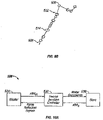
- a simplified controller schematic diagram 530 shows a master/slave controller 532 coupling a master input device 534 to a slave manipulator 536.
- the controller inputs, outputs, and computations are described using vector mathematical notation in which the vector x will often refer to a position vector in a Cartesian coordinates, and in which the vector q will reference a joint articulation configuration vector of an associated linkage (most often of the manipulator slave linkage), sometimes referred to as the linkage position in joint space.
- Subscripts can be appended to these vectors to identify a specific structure when ambiguity might otherwise exist, so that x m (for example) is a position of the master input device in the associated master workspace or coordinate system, while x s indicates a position of the slave in the workspace.
- Velocity vectors associated with the position vectors are indicated by a dot over the vector or the word "dot" between the vector and the subscript, such as xdot m or ⁇ m for the master velocity vector, with the velocity vectors being mathematically defined as the change in the position vector with a change in time ( dx m / dt for the master velocity vector example).
- controller 532 comprises an inverse Jacobian velocity controller. Where x m is a position of the master input device and ⁇ m is the velocity of the master input device, the controller 532 calculates motor commands for transmission to the manipulator 536 so as to effect slave end effector motions which correspond to the input device from the master velocities. Similarly, controller 532 can calculate force reflection signals to be applied to the master input device (and from there to the operator's hand) from the slave position x s and/or slave velocity ⁇ s .
- a number of refinements to this simple master/slave inverse Jacobian controller schematic are desirable, including those illustrated in Fig. 11 and described in detail in U.S. Patent No. 6,424,885 , the full disclosure of which is incorporated herein by reference.
- a processor 542 may by characterized as including a first controller module 544 and a second controller module 546.
- the first module 544 may comprise a primary joint controller, such as an inverse Jacobian master-slave controller.
- the primary joint controller of first module 544 may be configured for generating the desired manipulator assembly movements in response to inputs from the master input device 534.
- many of the manipulator linkages described herein have a range of alternative configurations for a given end effector position in space. As a result, a command for the end effector to assume a given position could result in a wide variety of different joint movements and configurations, some of which may be much more desirable than others.
- the second module 546 may be configured to help drive the manipulator assembly to a desired configuration, in some embodiments driving the manipulator toward a preferred configuration during master-slave movements.
- second module 546 will comprise a configuration dependent filter.
- both the primary joint controller of first module 544 and the configuration dependent filter of second module 546 may comprise filters used by processor 542 to route control authority for linear combinations of joints to the service of one or more surgical goals or tasks. If we assume that X is the space of joint motion, F(X) might be a filter giving control over the joints to i) provide a desired end effector movement, and ii) provide pivotal motion of the instrument shaft at the aperture site. Hence, the primary joint controller of first module 544 may comprise filter F(X).
- (1-F 1 F )( X ) could describe a configuration dependent subspace filter giving control actuation authority to the linear combination of joint velocities that are orthogonal to serving the goal of the primary joint controller (in this example, end effector movement and pivotal instrument shaft motion).
- this configuration dependent filter could be used by the second module 546 of controller 542 to service a second goal, such as maintaining a desired pose of the manipulator assembly, inhibiting collisions, or the like.
- Both filters may be further sub-divided into more filters corresponding to serving more specific tasks.
- filter F(X) could be separated into F 1 ( X ) and F 2 ( X ) for control of the end effector and control of the pivotal shaft motion, respectively, either of which may be chosen as the primary or highest priority task of the processor.
- the robotic processors and control techniques described herein will often make use of a primary joint controller configured for a first (sometimes referred to as a primary) controller task, and a configuration dependent filter which makes use of an underconstrained solution generated by the primary joint controller for a second (sometimes referred to as secondary) task.
- a primary joint controller configured for a first (sometimes referred to as a primary) controller task
- a configuration dependent filter which makes use of an underconstrained solution generated by the primary joint controller for a second (sometimes referred to as secondary) task.
- the primary joint controller will be described with reference to a first module, while the configuration dependent filter will be described with reference to a second module. Additional functions (such as additional subspace filters) and or additional modules of varying priorities may also be included.
- Controller 542 may employ the functions of the two modules simultaneously, and/or may have a plurality of differing modes in which one or both modules are used separately or in different ways.
- first module 544 might be used with little or no influence from second module 546 during master-slave manipulations, and the second module 546 having a greater role during setup of the system when the end effector is not being driven robotically, such as during port clutching or other manual articulations of the manipulator assembly. Nonetheless, in many embodiments both modules may be active most of or all the time robotic motion is enabled.
- the influence of the first module on the state of the manipulator assembly can be reduced or eliminated so as to change a mode of processor 542 from a tissue manipulator mode to a clutch mode.
- Fig. 10C illustrates a refinement of the simplified master-slave control schematic 540 from Fig. 10B , and shows how different modules might be used in different processor modes.
- first module 544 may, for example, comprise some form of a Jacobian controller having a Jacobian-related matrix.
- Second module 546 may, in a port clutch mode, receive signals from the slave 536 indicating a position or velocity of the slave generated at least in part by manual articulation of the slave manipulator linkage. In response to this input, the second module 536 can generate motor commands appropriate for driving the joints of the slave so as to allow the manual articulation of the slave linkage while configuring the slave in the desired joint configuration.
- the controller may use second module 546 to help derive motor commands based on a different signal b q ⁇ 0 .
- This alternative input signal to the second module 546 of controller 542 may be used to drive the manipulator linkage so as to maintain or move the minimally invasive aperture pivot location along the manipulator structure, so as to avoid collisions between a plurality of manipulators, so as to enhance a range of motion of the manipulator structure and/or avoid singularities, so as to produce a desired pose of the manipulator, or the like.
- b q ⁇ 0 can generally comprise and/or indicate (for example) a desired set of joint velocities, more generally representing a secondary control goal, typically in joint space.
- the processor may include separate modules and/or dependent configuration filters for clutching, secondary controller tasks, and the like
- a partial control schematic 550 illustrates modifications of the controller illustrated in Fig. 11 .
- Control schematic 550 very roughly represents a modification of portion 551 of the controller of Fig. 11 to facilitate control over manipulator assemblies have large numbers of degrees of freedom.
- the first module 544 comprises an inverse Jacobian velocity controller, with the output from calculations made using an inverse Jacobian matrix modified according to a virtual slave path 552.
- vectors associated with the virtual slave are generally indicated by a v subscript, so that a virtual slave velocity in joint space q ⁇ v is integrated to provide q v , which is processed using an inverse kinematic module 554 to generate a virtual slave joint position signal x v .
- the virtual slave position and master input command x m are combined and processed using forward kinematics 556.
- the use of a virtual slave (often having simplified dynamics) facilitates smooth control and force reflection when approaching hard limits of the system, when transgressing soft limits of the system, and the like, as can be more fully understood with reference to the '885 patent previously incorporated herein by reference.
- these structures will often comprise data processing hardware, software, and/or firmware.
- Such structures will often include reprogrammable software, data, and the like, which may be embodied in machine-readable code and stored in a tangible medium for use by processor 210 of workstation 200 (see Fig. 1A ).
- the machine-readable code may be stored in a wide variety of different configurations, including random access memory, non-volatile memory, write-once memory, magnetic recording media, optical recording media, and the like.
- Processor 210 may, as illustrated in Fig. 1A , comprise one or more data processors of workstation 200, and/or may include localized data processing circuits of one or more of the manipulators, the instruments, a separate and/or remote processing structure or location, and the like, and the modules described herein may comprise (for example) a single common processor board, a plurality of separate boards, or one or more of the modules may be separated onto a plurality of boards, some of which also run some or all of the calculation of another module.
- the software code of the modules may be written as a single integrated software code, the modules may each be separated into individual subroutines, or parts of the code of one module may be combined with some or all of the code of another module.
- the data and processing structures may include any of a wide variety of centralized or distributed data processing and/or programming architectures.
- the controller will often seek to solve for one particular manipulator joint configuration vector q for use in generating commands for these highly configurable slave manipulator mechanisms.
- the manipulator linkages often have sufficient degrees of freedom so as to occupy a range of joint states for a given end effector state.
- Such structures may (but will often not) comprise linkages having true redundant degrees of freedom, that is, structures in which actuation of one joint may be directly replaced by a similar actuation of a different joint along the kinematic chain.
- the primary joint controller of the first module When directing movement of highly configurable manipulators using the velocity controller of Fig. 12 , the primary joint controller of the first module often seeks to determine or solve for a virtual joint velocity vector q ⁇ v that can be used to drive the joints of slave 536 in such a way that the end effector will accurately follow the master command x m .
- an inverse Jacobian Matrix generally does not fully define a joint vector solution.
- the mapping from Cartesian command x to joint motion q in a system that can occupy a range of joint states for a given end effector state is a mapping of one-to-many.
- the controller may embody this relationship using a Jacobian matrix that has more columns than rows, mapping a plurality of joint velocities into comparatively few Cartesian velocities.
- Our solution J -1 ⁇ will often seek to undo this collapsing of the degrees of freedom of the slave mechanism into the Cartesian workspace.
- the primary joint controller of the first module may employ a number of different techniques to generate such a primary solution.
- a linear map such as a Jacobian matrix
- it may be said to have a non-trivial null space, the null space typically comprising a subspace of the input space spanning one or more dimensions.
- the pseudo inverse solution q ⁇ is equal to the combination of any particular solution q ⁇ part added to the homogeneous solution q ⁇ h .
- x ⁇ J q ⁇ part
- the least-mean-squares solution is one exemplary choice for the first term of the above general joint space solution equation, as it provides one particular solution to the Jacobian.
- This pseudo inverse yields the final solution vector with ⁇ q ⁇ part + q ⁇ h ⁇ 2 minimized, and is among the alternative pseudo inverses described below.
- J # J T J J T ⁇ 1
- J T is the transpose of the Jacobian matrix.
- this generally corresponds to a solution that achieves the primary control objective (such as a master-slave movement of the end effector corresponding to that of a handle of the input device) with the smallest joint velocities, a reasonable goal for many robotic systems. It is also mathematically extremely convenient, being one of the easiest solutions to compute.
- the desired control space x may optionally be more complex than simple end effector motion, particularly in systems in which the complexity of redundant manipulator linkages is justified.
- Combining of controller tasks or objectives will generally make use of a configuration dependent filter of the second module.
- filters may be used.
- multiple objectives may be adjoined or stacked to form an augmented desired vector, particularly if the objectives are independent.
- Such pivotal motion is sometimes referred to as a software center motion. Augmenting the problem statement in this manner is most easily applicable when the manipulator assembly has sufficient degrees of freedom to provide a solution to the augmented equation, as there generally are in the above-described robot manipulator assembly linkages. That is, the augmented Cartesian command vector (with the pivotal motion constraint) q ⁇ still has a lower dimension than the joint velocity vector q ⁇ , whose dimension is typically the number of manipulator joints.
- An exemplary augmented end effector and cannula control problem formulation may comprise computing a Jacobian J for each control objective.
- J eff mapping q ⁇ to ⁇ eff where eff is here used to indicate the vector and/or matrix that is associated with the end effector.
- a Jacobian J can maps the joint velocities of the manipulator assembly to the cannula Cartesian velocities, written ⁇ can .
- x ⁇ eff x ⁇ can J eff J can q ⁇
- position loops may be closed using signals from the manipulator assembly slave 536 to control positions (including location and orientation) as well.
- Additional control objectives such as driving toward a preferred collision-inhibiting pose or the like, may also be added in a similar manner. However, as such objectives are added the dimension of the desired vector space ⁇ may equal or surpass that of the solution space q ⁇ .
- the subspace filter of the second module may take another form.
- the pseudo inverse When the dimensions of the vector space and solution space are equal, the pseudo inverse should become a true inverse, and the minimum-norm pseudo inverse conveniently reduces to the true inverse. Should more augmented solutions be sought, however, the controller and the robot will not in general have sufficient degrees of freedom to satisfy all the constraints. Such a problem is described as over-constrained, so that a new kind of pseudo inverse may be created. Such a pseudo inverse attempts to compromise in some mathematical sense, returning a solution that does not perfectly satisfy all of the constraints but may still be mathematically determined to be the best solution in some identifiable sense. For example, a residual error resulting from the imperfect inverse may be computed, such as by using the minimum two-norm pseudo inverse to return a solution that minimizes the two-norm of the residual error.
- Examples of additional constraints that may be added include maintaining a pose constraint, and/or avoiding a collision with an object which may be present in the workspace.
- ⁇ k is the desired control variable
- q ⁇ j is the joint velocities of joints 1, 2,... n
- J kj are the Jacobians of the desired control variable for each joint
- r is the residual error appropriate for our quadratic cost function C.
- an augmented controller we can control a joint to maintain a pose using the above framework by creating a desired control variable ⁇ k and making it identical to a selected joint q ⁇ j .
- the augmented Jacobian can in this example be a trivial matrix with a one in the column for the selected joint.
- the analysis is more complex for an over-constrained system in comparison to an under-constrained system.
- Robots in general, and surgical robots in particular should be designed and controlled so as to make advantageous use of all their joints.
- a plurality of commands may optionally be combined by the controller with associated weights, for example by applying a weighted minimum norm solution.
- the minimum norm can be computed with respect to a set of basis vectors representing the solution space.
- the solution may then comprise a linear combination of those basis vectors. While basis vectors are sometimes visualized as one unit in the x direction, one unit in the y direction, etc., this is not necessarily required. For example, joints may differ significantly, with some being axial or prismatic, others being pivotal or rotational, and the like.
- basis vectors may be understood from a simple example, in which e 1 is one degree/sec for a first motor, e 2 is one degree/sec for a second motor, etc, and in which an initial minimum norm solution space is computed.
- This solution space could be arbitrarily weighted by instead choosing different basis vectors. For example, we could make e 1 equate to ten degrees/sec for the first motor, while e 2 remains one degree/sec for the second motor.
- a minimum norm solution will tend to make coefficients for e 1 no bigger, on average, than those for e 2 and the rest. Thus, this weighting approach can tend to make the first motor's velocity smaller, because of the weighting of basis functions we have chosen.
- e 1 may be one degree/sec in the positive direction for the first motor, and one degree/sec in the positive direction for the second motor.
- e 2 could then be one degree/sec in the positive direction for the first motor, and one degree/sec in the negative direction for the second motor.
- C weighted r T W T Wr , where W is a weighting matrix, and r is the residual error. In this sense, we weight the residual error as desired, thereby helping to shape the answer.
- weighting can be used to make some parts of the solution more important than others.
- W can be made diagonal with large weights for important components and small weights for less important components of the augmented solution vector.
- linear combinations of any solution components can be arbitrarily weighted.
- condition number For robotic systems, the loss of precision associated with an increase in condition number happens when the Jacobian becomes ill conditioned, which in turn happens near singularities. As the condition number grows, the map acts more and more like its null space is growing by one or more dimension, but the effect is continuous, not discrete. Instead, a new subspace of joint (solution) vectors map almost to zero in the desired (master) vector space. Any noise, even round-off error in numeric calculations, can and often does result in phantom solutions, in which unrealistic joint velocities are commanded for minor velocities in command space, including minor contributions due to noise.
- a number of subspace filter techniques can address this ill-conditioned map effect, including conditioning the solution by truncating the singular value decomposition ("SVD") of the Jacobian, effectively forcing the nearly grown null space to grow a full dimension.
- SVD singular value decomposition
- Bayesian estimation which is also referred to as maximum a posteriori estimation. In its simplest form it reduces to something equivalent to a regularizing inverse.
- the main concept is to find the free parameters q ⁇ j that maximize the a posteriori probability density function of a noisy measurement p(q ⁇ j , ⁇ j ,... , ⁇ n ).
- PDFs probability density functions
- the second is the a priori (or prior) distribution for the solution vector.
- A is a matrix formed of the variances of the measurement process divided by the variances of the prior distribution.
- Bayesian methods change the solution. In this case, the change is physically motivated by an optimization technique meant to handle measurements in the presence of noise, and to handle the availability of prior information about the probable solution.
- a still further augmented optimization subspace filter approach which may be applied to over constrained redundant degree of freedom surgical robotic systems is constrained convex optimization.
- a minimum norm solution based on minimizing a quadratic form has the mathematical elegance of reducing to a system of linear equations.
- these simultaneous linear equations may be solved rapidly and with high accuracy, and are approachable and easy to understand, and this ease of implementation certainly encourages their use.
- a class of such problems is termed convex optimization, and a corresponding class of algorithms exists that yield efficient solutions, including those algorithms described by Boyd and Vandenberghe.
- controllers of surgical robotic systems having redundant degrees of freedom might also benefit from mathematical approaches for addressing constraints that respect priority.
- the above discussion has largely centered on optimization of a problem where constraints are imposed using augmented optimization. However, there may be differences in importance between a central, main control problem and any desirable, but not necessarily required solutions that we can add in.
- Several mathematical mechanisms are introduced below for making constraints soft, so that they fold back or can be relaxed gracefully as the main control problem gets harder, employing more of the degrees of freedom of the system.
- An example of a soft constraint would be to maintain an elbow or joint apex of a manipulator pointing up, as described above regarding Figs. 5A and 5B .
- Another constraint might be to maximize the robot's workspace dexterity, or some other mathematical measure or robotic effectiveness.
- We might, for example, wish our controller to gradually abandon these secondary goals as the primary task (for example, complying with an end effector movement command vector), thereby allowing the system to achieve the primary objective at the cost of these soft, lower priority goals.
- we might need and use the otherwise extra degrees of freedom to avoid a singularity or the like.
- One way to establish a system having a plurality of constraints, tasks, or goals with priorities therebetween is to construct the secondary task as an augmented part of the solution, per the discussion above.
- We can also adjust this weighting matrix during use so that the weighting is neutral when the robot is in its sweet spot, while the weighting might exert a very strong clamp on any augmented solution (making the secondary constraint contribute almost nothing to the final solution) as the difficult region was approached. It is also possible to turn on and off the weighting altogether, so as to achieve a discrete switch that respects priority. Similar techniques may be used for the regularized solution and the Bayesian approach. For example, the parameter ⁇ , as well as the prior distribution, may be tuned in a configuration dependent manner.
- projector methods may make use of input vector bq ⁇ 0 .
- J eff mapping q to x for the end effector
- any task that can be written as a linear controller of rates with a position feedback such as the remote center cannula motion task described above.
- Still further secondary tasks may be performed using projection, augmentation, and/or other methods, including some or all of the robotic manipulations and/or set up methods described above.
- the generation of secondary tasks to perform collision avoidance described herein and elsewhere in the literature can, for example, be revised so as to inhibit collisions between two simultaneously moving manipulator assemblies.
- One solution will use the general formalism of augmented tasks to generate rate controllers, as discussed above.
- Additional modified control approaches may be implemented for other operation modes. For example, to lock an arm or manipulator assembly, or a subset of the degrees of freedom of such a structure (see clutching below), we can deliberately clamp some or all of the output vector of the first module 544 to zero. To re-establish master-slave following, we release the clamp, preferably after satisfying elementary matching conditions to rule out jump discontinuities in the input command.
- an instrument clutch mode will generally allow manual articulation of the manipulator assembly with limited degrees of freedom.
- an assistant may want to be able to manually move the manipulator assembly so as to advance and retract the instrument through the access site, to pivot the instrument about the access site to orient and position the new end effector, and the like.
- a port clutch mode may allow the canula or access site to be moved (and optionally to identify the new access site location when the move is completed), but may maintain an orientation and/or pose of some or all of the manipulator assembly during manual movement.
- clutching is direct: one simply turns off the controller for those joints that are free to move.
- the controller can effect this motion, which will often be different than any degree of freedom of the mechanical system, by defining any desired arbitrary linear combination of rates that can be treated as a single degree of freedom that the operator may manipulate, optionally while some or all of the other mechanical degrees of freedom remain locked.
- This general concept includes port clutching, instrument clutching, elbow clutching (in which an intermediate elbow is allowed to move, for example, from an upward oriented apex configuration around to a laterally oriented apex configuration while movement at the end effector remains inhibited), and other clutching modes. Normal joint-by-joint clutching falls out as a special case.
- Still further tasks or goals of the system may be implemented using the controller techniques described herein. Adaptive filtering and learning of a pivotal access site location from instrument movements are described below. Additionally, haptic constraints may be implemented using another variation on these techniques.
- haptic constraints it is often useful to provide cues to the operator during the manipulation of the slave arm via the master input device. For example, it may be desirable to indicate to the operator to keep away from suboptimal configurations that will cause controllability problems later.
- One simple method to provide such haptic constraints is to implement a joint limit technique.
- Another method is to turn on a one-sided servo whenever a threshold is crossed. This can be done using any of the projector or augmentation methods above.
- a one-sided servo would often push back toward or away from a control point if the sensors indicate that the threshold is crossed and motion is further in the wrong direction.
- a velocity that is parallel to the boundary can be described for every point along the boundary.
- a dot product of the velocity vector and the threshold then indicates whether the operator is moving toward or away from the boundary, and the projection in the wrong direction is resisted. This can all be done with the above-described projector operators and a comparison with zero.
- a software center surgical robotic manipulator assembly 560 has particular advantages relating to movement of a pivotal center of motion 562 of a robotic instrument 564 with movement of an associated port site or minimally invasive surgical access into a patient 566.
- Manipulator assembly 560 may be mounted to a patient side table, ceiling mount or floor mount, and can compensate for port site motion (e.g., patient breathing) by independently controlling the location of the port site.
- the port site location can be controlled in response to Cartesian force information at the cannula pivotal center point as sensed by a force sensing cannula 568.
- the coordinate frame attached to the cannula is designated Ocan in Figure 13 .
- This frame is distinct from a base frame, Obase, at the base of the manipulator and the tip frame, Otip, at the tip of the instrument.
- the Cartesian forces on the cannula can be resolved to control the position of the cannula (Ocan).
- the torques about Ocan are not needed for such position control.
- Some or all of the forces at the port can be resolved using a force sensing system of cannula 568, and/or at least some of the forces may be resolved using a force sensing system of the instrument 564, the manipulator assembly 560 (e.g., joint torque sensors of the manipulator), or the like.
- control laws can move the cannula position in response to reaction forces at the cannula.
- One example of such a control law is to set a commanded cannula Cartesian force to zero. The controller will then try to move the manipulator assembly such that the resulting Cartesian force on the cannula is minimized. It is also possible to set a nonzero commanded cannula force, e.g., 5 lbs in the positive Z cannula direction to have the arm help retract the cannula from the patient. This can also be achieved using the same controller.
- FIG. 13A shows the overall block diagram for the cannula motion controller as it would fit into an overall software center tele-operation controller.
- Signals from force sensors 572 can be derived from the sensor characteristics and their placement in the arm.
- a transform module 574 (typically a Jacobian operator) transforms measured force sensor information into the reference frame of Cartesian cannula forces.
- Filter module 578 creates a filtered error signal from the actual cannula force and the commanded cannula force.
- the commanded slave tip position 580 comes from the master side of the teleoperation loop (see, for example, Fig. 11 ) and a commanded slave tip velocity 582 may also be provided.
- Hybrid controller module 584 accepts command and actual slave position and velocity signals, along with filtered cannula force error signals, and creates joint motor torque signals.
- the dynamics of the software center manipulator assembly are shown as 586, which interact with the dynamics of the patient environment 588.
- Figs. 13B and 13C show representative control arrangements or algorithms for filter module 578 and hybrid controller 584, respectively.
- a simple compare module 590 can create an error signal between commanded and actual cannula force. The filtered error can then be generated by a low pass filter 592.
- a good method of control may be to convert the commanded cannula force into a commanded cannula motion 594. This can be done by creating an incremental commanded position proportional to the cannula force error and adding this incremental cannula position to the current (actual) cannula position to create a commanded cannula position.
- the commanded cannula position is vector assembled 596 with the commanded slave tip position, to create a command position vector for the manipulator assembly. This is combined with actual joint positions and velocities and fed into the software center slave controller 598 to create commanded motor torques, which are in turn used to drive the manipulator assembly motors.
- pivot point PP is the position relative to the minimally invasive access port at which an instrument shaft pivots.
- Pivot point PP may, for example, be calculated by initially determining an original position of the interface between the manipulator instrument 14.1 and a unit vector Uo which has the same orientation as the instrument shaft.
- the pivot point position PP(x,y,z) values can be derived from various sensors of the manipulator assembly.
- the instrument can be within a first coordinate frame (x,y,z) which has the angles ⁇ 4 and ⁇ 5.
- an angular movement of the instrument ⁇ can be computed by taking the arcsin of the cross-product of the first and second unit vectors Uo and U1 of the instrument in accordance with the following line equations Lo and L1.
- T a vector which is a cross-product of unit vectors Uo and U1.
- the unit vector of the new instrument position U1 may again be determined using the position sensors and the transformation matrix described above. If the angle ⁇ ⁇ is greater than a threshold value, then a new pivot point may be calculated and Uo set to U1.
- the pivot points of the instrument in the first orientation Lo (pivot point Ro) and in the second orientation L1 (pivot point R1) can be determined, and the distance half way between the two points Ro and R1 is computed and stored as the pivot point R ave of the instrument.
- the pivot point R ave is determined by using the cross-product vector T.
- the pivot point location can be regularly continually updated with the above described calculations.
- FIG. 14A, 14B , and 15 another control system schematic 400 illustrates how a movement of the master controller or manipulator can be used to calculate a corresponding movement of a surgical instrument so that the instrument pivots about a pivot point using an alternative controller architecture.
- the processor computes output signals for the manipulators so that the instruments move in conjunction and coordination with the movements of the master input handle.
- Many aspects of control system 400 are more fully described in U.S. Patent No. 6,699,177 , the full disclosure of which is incorporated herein by reference.
- a pivot point calculation module 404 the location of a pivot point at which an instrument is inserted into an internal surgical site can be calculated by a pivot point calculation module 404 from instrument movements.
- the various modules shown in Figs. 15 and 16 may again comprise hardware, software, firmware, a combination of hardware and software, or the like.
- the modules will often comprise data processing hardware configured to perform the calculations described herein using software, and the calculations of multiple modules may be integrated together in a common program or module, and/or the calculation of a single module may be separated into multiple programs or subroutines to be run on separate processor boards.
- the above descriptions enable the pivot (center) point to be determined/estimated through software.
- different modes characterized by the compliance or stiffness of the system can be selectively implemented. More particularly, different system modes over a range of pivot points/centers (i.e., ranging from one have a passive pivot point to one having a fixed/rigid pivot point) can be implemented after an estimate pivot point is computed. For example, in a fixed pivot implementation, the estimated pivot point can be compared to a desired pivot point to generate an error output which can be used to drive the instrument's pivot to the desired location.
- an estimated pivot point can be used for error detection and consequently safety because changes in estimated pivot point locations may indicate that the patient has been moved or a sensor is malfunctioning thereby giving the system an opportunity to take corrective action.
- the interaction between the moving instrument and the tissue of the minimally invasive aperture may be determined at least in part by the processor, the processor optionally allowing the compliance or stiffness of the system to be changed throughout a range extending from a passive pivot point to a fixed pivot point.
- the proximal end of the instrument may be moved in space while the motors of the instrument holder wrist joint apply little or no torque, so that the instrument acts effectively like it is coupled to the manipulator or robotic arm by a pair of passive joints.
- the interaction between the instrument shaft and the tissue along the minimally invasive aperture induces the pivotal motion of the instrument about the pivot point PP.
- the surgical instrument was not inserted into the minimally invasive aperture or otherwise constrained, it may point downward under the influence of gravity, and movement of the manipulator arm would translate the hanging instrument without pivotal motion about a site along the instrument shaft.
- the location of the minimally invasive aperture may be input or calculated as a fixed point in space.
- the motors associated with each joint of the kinematic chain disposed proximal of the pivot point may then drive the manipulator so that any lateral force laterally against the shaft at the calculate pivot point results in a reaction force to keep the shaft through the pivot point.
- Such a system may, in some ways, behave similar to mechanically constrained remote center linkages. Many embodiments will fall between these two extremes, providing calculated motion which generally pivots at the access site, and which adapts or moves the pivotal center of motion within an acceptable range when the tissue along the minimally invasive access site moves, without imposing excessive lateral forces on that tissue.
- a software center manipulator assembly controller such as that illustrated in Fig. 12 can leave the software center rather soft or lightly held so that the tissue forces applied by the interaction with the patient are allowed to overpower the commands sent to the manipulator motors.
- Such calculated saturation of the manipulator drive torques may be allowed while still controlling the end effector position to quite tight tolerances, since all motions of the manipulator assembly can be determined from the sensors of the manipulator.
- Several mechanisms may be applied for gradually increasing the stiffness of the software center control, including the weighted augmentation solutions discussed above. By starting with a small weighting value for the remote center, and by gradually increasing those weights to be on a par with the end effector weights, one could (for example) gradually stiffen control over the pivotal center location.
- the body wall and any other exogenous forces applied to the manipulator assembly can affect the motion of the pivotal center if the pivotal center is held softly by the controller.
- the above-described calculations for determining the remote center location can be applied if the instrument is allowed to passively pivot adjacent the interface with the manipulator, for example. As the variance of the estimates for the pivotal motion center decreases, the weighting factor or gain may be increased. Tracking of the changes in pivotal center location may allow identification of and compensation for cyclical physiological movements such as patient breathing, beating of the heart, or the like. In some embodiments, similar calculations will allow the controller to compensate for movement of the patient such as by reorienting a surgical table, repositioning a patient on the surgical table, or the like.
- the systems described herein may optionally include a modified manipulator command module 406 of controller 400 having a software center joint command calculation module 410 as illustrated in Fig. 16 .
- Software center module 410 of processor 210 receives an input command corresponding to a desired end effector motion, typically in the form of signal generated in response to a master input handle movement.
- Software center module 410 calculates the desired corresponding end effector movement or vector at calculation module 412, optionally using coordinate system transformations such as those described in Patent Nos. 6,424,885 and/or 6,699,177 .
- the desired end effector movement is then transmitted to an inverse kinematics solver 414.
- the desired end effector motion is also used by a remote center locator 416 so as to generate a solved center about which the instrument will pivot.
- the remote center locator 416 makes use of actual joint motion information from the slave manipulator 418.
- the information from manipulator 418 may comprise actual joint motions from prior end effector movements.
- the data may originate in the form of positions of each of the individual joints from potentiometers or the like, discrete steps of the individual joints from encoders or the like, or a wide variety of alternative motion indicators.
- joint torques as detected at the joints of the manipulator may also be provided, and both joint positions and joint velocities may be transmitted to a forward kinematics module 420.
- the forward kinematics module 420 can calculate an observed minimally invasive aperture pivotal center location from the behavior of the slave manipulator during prior movements of the instrument.
- the software center module 410 may also determine forces associated with the pivoting about the minimally invasive aperture, properties of the tissue tract (for example, the lateral or pivotal spring forces applied by the tissue tract to the instrument during movement of the instrument shaft and/or any lateral movement of the patient anatomy adjacent the aperture) and the like. Still further, properties of the observed pivotal center may also be determined. For example, the software center module 410 may determine any cyclical movements of the observed pivotal center with a physiological activity such as breathing or beating of the heart. Shifting of the pivotal center with changing pivotal angles or orientations may also be identified.
- intercostal access to the chest cavity may result in a first pivotal center when a instrument inserted between the ribs is pivoted generally across the rib orientation, and a slightly different pivotal center when the instrument is angled along the lengths of the adjacent ribs.
- Tissue stiffness may also vary along the axis of the tissue tract and/or at differing distances from the tissue tract, so that pivoting of a shaft inserted through a minimally invasive aperture at a relatively small angle may result in a pivotal center which is disposed at a first point along a tissue tract extending through the abdominal wall, while increasing the angle of the shaft inserted through the same tract may shift the pivotal center axially along the tissue tract either proximally or distally.
- the observed pivotal center information from the forward kinematics module 420 may be combined with the commanded end effector motion from desired end effector calculation module 412 so as to generate a solved or desired center of the desired motion.
- the observed pivotal center and commanded tip motion may be combined using an adaptive filter, and the input to the inverse kinematic solver from the combination of the observed pivotal center and the commanded end effector motion may comprise a desired remote center motion 422.
- manipulator linkages which are not easily back driven will tend to keep a remote center location at a calculated position. Assuming the drive system of the linkage is not overpowered, the observed remote center will remain within a close proximity to the desired or calculated remote center location, with the difference between the observed center and desired center often falling within a relatively small servo error of the manipulator.
- the system may determine that the remote center should be removed to alleviate forces and/or torques applied to the manipulator structure.
- the forces and/or torques may be applied to and measured at the cannula, for example, by reactive forces of the tissue against the cannula, by physiological movement of the patient during breathing or patient repositioning, or the like.
- an operator may manually push on the arm to move the remote center to a new location, optionally before, during, or after transmitting a pivot center repositioning signal to the processor, such as by pushing a port clutch button.
- a large number of computational methods may be used to choose a new remote center based on the data provided by such manual movement of the manipulator linkage.
- the output of such calculations may be termed a solved center or a desired center, and will often represent an input from a system user to the processor, optionally by releasing the port clutch input when the appropriate structure along the kinematic chain of the manipulator assembly (such as a cannula) is disposed at the desired access site location.
- a solved center or desired center may simply be a filtered version of an observed center.
- Such back drivable linkages lend themselves more directly to observing actual motions of the remote center and adjusting the control appropriately.
- a torque or force sensor to measure disturbance forces acting on the arm at the pivot center (such as a cannula force sensor) may facilitate such pivot location movement, rather than relying solely on joint torque or position measurements.
- the shaft of the instrument between the end effector and the proximal instrument housing will typically extend through the minimally invasive aperture.
- the motion of this intermediate portion of the instrument will be calculated so that the instrument does not impose injury on the patient, but instead remains within the minimally invasive access site.
- the instrument may rotate about its shaft, and the shaft may be inserted distally or withdrawn proximally along the shaft axis.
- the vector of the commanded Cartesian velocities and angular velocities of the tip of end effector may be provided from the slave vector calculator 414, the exemplary end effector vector comprising a 1 ⁇ 6 vector, with actuation of grip on end effector often being handled separately from the inverse kinematic computations.
- the desired remote center motion 422 input into the inverse kinematic solver may comprise a vector of Cartesian velocities of the pivotal center, such as a 1 x 3 vector.
- inverse kinematic solver 414 can be used for manipulator structures which are a combination of a compliant or passive rotational center and a more rigidly calculated rotational center.
- Inverse kinematic solver 414 may nonetheless make use of controller schemes similar to those of more constrained mechanical systems, such as those described in U.S. Patent No. 6,493,608 , the full disclosure of which is incorporated herein by reference. More specifically, the use of modified inverse kinematics with a feedback tuned to correct for integrator drift may have some benefits for the joint motion calculator 410 of Fig. 16 . However, certain modifications to the inverse kinematic solver 414 may be employed to adapt the joint calculator for use with a larger number of degrees of freedom and/or for the use of a calculated remote center.
- inverse kinematic solver 414 uses the desired end effector motion and the desired pivotal center motion to determine velocities of the instrument.
- the velocities will include a vector of the desired Cartesian velocities of the end effector, the desired angular velocities of the end effector, and the Cartesian velocities of the pivotal center, often in the form of a 1 ⁇ 9 vector V.
- q ⁇ base W ⁇ 1 J T JW ⁇ 1 J T ⁇ 1 V in which W is a weighting matrix and J is the Jacobian matrix.
- the Jacobian matrix is a 9 x 10 matrix.
- the exemplary arms will again often include more degrees of freedom than the combination of the degrees of freedom of the end effector in space (often 6) and the constraint of maintaining the instrument shaft at the aperture (3), so that they are underconstrained for the end effector and shaft pivoting tasks.
- these linkage systems may have more than 10 degrees of freedom, and their kinematic chains often define a null space or range of alternative configurations and/or joint velocities which the kinematic chain can have for a given end effector position.
- auxiliary joint velocities q aux that minimizes one or more cost functions can then be computed, with the cost function often having a configuration which drives the manipulator away from joint range-of-motion limitations, away from singularities, free from obstacles, and the like.
- These auxiliary joint velocities can then be projected into the null space of the Jacobian matrix.
- kinematic solver 414 can calculate the joint motions based at least in part on information regarding the motions of other manipulators.
- a pose optimizer module 430 receives actual joint motion data from the manipulator, and also receives actual joint motion information from the other manipulators. Based on the motions of the manipulators, the pose optimizer calculates additional inverse kinematic constraints to be input into the inverse kinematic solver 414.
- the pose optimizer may again drive the joint configuration of the kinematic chain using a goal function, such as to enhance separation between adjacent manipulators while effecting the commanded movement of the end effector, and while also maintaining an intermediate portion of the instrument within a minimally invasive aperture site.
- Pose optimizer 430 thereby takes advantage of the excess degrees of freedom of the kinematic linkage (beyond those of the end effector in the surgical site), as can be understood with reference to Figs. 5A and 5B .
- manipulator 304 holds instrument 306 at a given location in space.
- An intermediate joint J4 of the manipulator is configured so that the axes of the links coupled together at joint J4 generally define a downward oriented apex 350.
- manipulator arm can be driven from this downward apex configuration to an upward oriented apex configuration illustrated in Fig. 5B , with the upward oriented apex indicated by reference numeral 352.
- the end effector (and in fact, the entire instrument) may be at the same location in space relative to the base supporting the manipulator when the manipulator is in either of these two configurations, and while the manipulator moves between these two configurations.
- adjacent manipulators such that collisions between the manipulators are inhibited.
- adjacent manipulators when two manipulators are supported by one or more bases such that the manipulator arms are adjacent to each other, and when the surgical instruments supported by the manipulators are inserted through adjacent minimally invasive apertures, having the manipulators in similar configurations may lead to configurations when the manipulators move towards each other.
- adjacent manipulators alternate between a downward oriented apex configuration such as that illustrated in Fig. 5A and an upward oriented apex configuration such as that illustrated in Fig. 5B
- the overall configuration of the manipulator system may have fewer or no collisions.
- pose optimizer 430 and joint calculator 410 may be implemented in different embodiments for a multiple manipulator system.
- a joint calculation and associated pose optimization may be performed individually for each manipulator motion. The calculations will be performed iteratively for each manipulator, and the joint calculations may be performed by a single program running on a single processor board, by separate programs running on dedicated processor boards, or the like. Regardless, at least some of the pose optimization program may run a pose optimization routine specifically for a single manipulator.
- a single global pose optimizer may take observed slave motion data from a plurality of manipulators, optionally from all of the manipulators in the manipulator system. From this information, a globally optimized solution for the manipulator pose may be computed. This globally optimized solution may then be used as an input for the inverse kinematic solver 414 for each of the manipulators. Still further alternatives are possible, including using inverse kinematic solver to simultaneously determine actual joint motions of all joints throughout the manipulator arms.
- each manipulator assembly should be compact and highly dexterous.
- Compact size enables multiple arms to share a limited space available in a vicinity of a patient while minimizing collisions between manipulator assemblies during a surgical procedure.
- Compact size also reduces the torque and power specifications of the motors and actuators, and helps make the system more safe for surgical staff and the patient.
- Compact manipulator assembly structures also tend to have lighter weight, which reduces the size of the manipulator support and setup system, and can make a manual setup process easier for a surgical staff.
- High dexterity generally allows the surgical end effector to be located, oriented, and moved within the patient's body in the most clinically advantageous manner.
- Fig. 18A illustrates an exemplary kinematic structure which provides both compactness and high dexterity.
- the exemplary manipulator assembly 304 includes a kinematic chain of links and joints defining two arm portions.
- a first arm portion extends between pivotal joint J2 and pivotal joint J4 and has a length of L1.
- a second arm portion extends between pivotal joint J4 and pivotal joint j6 and has a length of L2.
- Lengths L1 and L2 of these first and second arm portions 602, 604 each extend along an associated axis of the associated arm portion, and a roll joint is present along each arm portion (see joints j3 and j5 in Fig. 6 ).
- the useful work volume of manipulator assembly 304 is generally improved by keeping lengths L1 and L2 within about 20% of one another. If these lengths differ significantly more than that amount, volumetric holes or unreachable areas in the work volume can become problematic. Balancing lengths L1 and L2 also help to balance the angular range of motion for driving the joints J2 and J4. As the mechanical design of the joints gets significantly more complex when the range of motion increases excessively, it is generally beneficial to avoid designs involving very large ranges of motions about these pivotal joints.
- a distal width W d is less than a proximal width Wp.
- manipulator assembly 304 will move from the planar configuration during robotic operation, it will often be advantageous to drive the linkages so as to maintain a substantially planar profile along plane PL, and/or to minimize the protrusions or widths of the arm from the central plane in a direction of an adjacent manipulator assembly.
- Such limiting of lateral kinematic offsets in the arm design and/or drive control logic may avoid mechanical protrusions or bumps which can potentially collide with other manipulator assemblies, the setup and manipulator support structure, the patient, surgical staff, and the like. Reducing offsets from plane PL may also help avoid holes or unreachable spaces in the arm work volume.
- Driving the manipulator to avoid unnecessary lateral offsets from a planar configuration can be achieved by the augmented and projector solutions described above, with this constraint or task often being lower in priority that end effector following, pivoting about the cannula, and the like.
- adjacent arms 304a and 304b which are designed for use along an associated plane PL 1 and PL2, when driven by controllers having a goal of maintaining a planar configuration of each arm at planes which are laterally and/or angularly offset, can inhibit collisions between these adjacent arms.
- alternating adjacent arms between apex upward and apex downward configurations may also be employed, as described above.
- range of motion may be enhanced by providing at least one of the minimum ranges of motion in the following table for the associated joint, preferably some of the ranges of motions in this table, and ideally all of the minimum ranges of motions ("ROM") in the following table: Joint Min ROM 1 90° 2 135° 3 180° 4 180° 5 180° 6 90° 7 8 inches
- the upper arm roll joint J3 can be thought of as the redundant or extra degree of freedom of the arm. Without it, manipulator assembly 304 would work very effectively in three-dimensional space.
- the arm is able to attain an infinite number of poses or configurations for a given end effector position, even while the shaft of the instrument remains constrained to pivotal motion about a minimally invasive aperture. This can allow the arm to avoid obstacles, avoid collisions with other arms, and the like. This flexibility also can be used to optimize the kinematics of the manipulator linkage so as to avoid joint limits, singularities, and the like.
- the manipulator linkage 304 When used for robotic surgical systems having a plurality of manipulator assemblies, the manipulator linkage 304 will ideally be able to invert itself from an apex oriented downward configuration to an apex oriented upward configuration and back, as illustrated in Figs. 5A and 5B .
- This can enable adjacent arms to alternate between these two configurations in primary pose (e.g., nominal starting pose), giving each arm a larger obstacle-free workspace in which to move, for example.
- This ability to invert the arm is facilitated by providing upper arm roll joint J3 with at least 180 degrees of travel, preferably with 360 degrees or more of travel.
- angle J6A when the end effector of the instrument is as close as possible to the apex of the manipulator arm will preferably be 45 degrees or less
- angle J6B will preferably be 135 degrees or more when the end effector is moved as far away as possible from the apex of arm 304.
- the sensors will often be disposed on the manipulator assembly's outer surfaces.
- the sensors may comprise contact and/or proximity sensors, and may be monitored on a real time or near real time basis by the controller.
- the control system may take appropriate action such as driving the manipulator to a different pose, generating a soft fault, generating a hard fault, or simply generating some type of alert, such as an audible beep, a warning light, or the like to the system operator.
- the appropriate action may depend on the location of the sensor and/or other characteristics of the collision detection signal.
- Suitable collision sensors may employ tape switches such as those commercially available from Tape Switch Corporation of New York; flexible sensing arrays such as those developed by the University of Tokyo (including Takao Someya), and described in an article entitled " Flexible Sensors Make Robot Skin” in www.trnmag.com on September 22/29, 2004 ; individual force sensing resistors or force sensing resistor arrays available commercially from Interlink Electronics; capaciflector active or passive capacitive sensing systems such as those developed by John Vranish at NASA-Goddard, or the like.
Applications Claiming Priority (6)
| Application Number | Priority Date | Filing Date | Title |
|---|---|---|---|
| US200513342305A | 2005-05-19 | 2005-05-19 | |
| US11/133,423 US8004229B2 (en) | 2005-05-19 | 2005-05-19 | Software center and highly configurable robotic systems for surgery and other uses |
| EP06752435.5A EP1885273B2 (de) | 2005-05-19 | 2006-05-08 | Hochkonfigurierbare Robotersysteme für die Chirurgie und andere Anwendungen |
| PCT/US2006/017843 WO2006124390A2 (en) | 2005-05-19 | 2006-05-08 | Software center and highly configurable robotic systems for surgery and other uses |
| EP10196666.1A EP2332479B1 (de) | 2005-05-19 | 2006-05-08 | Softwarecenter und Robotersysteme mit hoher Konfigurierbarkeit für chirurgische und andere Verwendungen |
| EP17172599.7A EP3231388B1 (de) | 2005-05-19 | 2006-05-08 | Softwarecenter und robotersysteme mit hoher konfigurierbarkeit für chirurgische und andere verwendungen |
Related Parent Applications (5)
| Application Number | Title | Priority Date | Filing Date |
|---|---|---|---|
| EP17172599.7A Division EP3231388B1 (de) | 2005-05-19 | 2006-05-08 | Softwarecenter und robotersysteme mit hoher konfigurierbarkeit für chirurgische und andere verwendungen |
| EP17172599.7A Division-Into EP3231388B1 (de) | 2005-05-19 | 2006-05-08 | Softwarecenter und robotersysteme mit hoher konfigurierbarkeit für chirurgische und andere verwendungen |
| EP06752435.5A Division EP1885273B2 (de) | 2005-05-19 | 2006-05-08 | Hochkonfigurierbare Robotersysteme für die Chirurgie und andere Anwendungen |
| EP06752435.5A Division-Into EP1885273B2 (de) | 2005-05-19 | 2006-05-08 | Hochkonfigurierbare Robotersysteme für die Chirurgie und andere Anwendungen |
| EP10196666.1A Division EP2332479B1 (de) | 2005-05-19 | 2006-05-08 | Softwarecenter und Robotersysteme mit hoher Konfigurierbarkeit für chirurgische und andere Verwendungen |
Publications (1)
| Publication Number | Publication Date |
|---|---|
| EP3973910A1 true EP3973910A1 (de) | 2022-03-30 |
Family
ID=36808871
Family Applications (13)
| Application Number | Title | Priority Date | Filing Date |
|---|---|---|---|
| EP17172599.7A Active EP3231388B1 (de) | 2005-05-19 | 2006-05-08 | Softwarecenter und robotersysteme mit hoher konfigurierbarkeit für chirurgische und andere verwendungen |
| EP10196673.7A Active EP2332484B2 (de) | 2005-05-19 | 2006-05-08 | Softwarecenter und Robotersysteme mit hoher Konfigurierbarkeit für chirurgische und andere Verwendungen |
| EP10196671.1A Active EP2332483B1 (de) | 2005-05-19 | 2006-05-08 | Softwarecenter und Robotersysteme mit hoher Konfigurierbarkeit für chirurgische und andere Verwendungen |
| EP10196670.3A Active EP2332482B1 (de) | 2005-05-19 | 2006-05-08 | Softwarecenter und Robotersysteme mit hoher Konfigurierbarkeit für chirurgische und andere Verwendungen |
| EP10196666.1A Active EP2332479B1 (de) | 2005-05-19 | 2006-05-08 | Softwarecenter und Robotersysteme mit hoher Konfigurierbarkeit für chirurgische und andere Verwendungen |
| EP10196669.5A Active EP2332481B1 (de) | 2005-05-19 | 2006-05-08 | Softwarecenter und Robotersysteme mit hoher Konfigurierbarkeit für chirurgische und andere Verwendungen |
| EP17172595.5A Active EP3231387B1 (de) | 2005-05-19 | 2006-05-08 | Softwarecenter und robotersysteme mit hoher konfigurierbarkeit für chirurgische und andere verwendungen |
| EP21199257.3A Pending EP3973910A1 (de) | 2005-05-19 | 2006-05-08 | Software-center und robotersysteme mit hoher konfigurierbarkeit für chirurgische und andere verwendungen |
| EP10196665.3A Active EP2332478B1 (de) | 2005-05-19 | 2006-05-08 | Softwarecenter und Robotersysteme mit hoher Konfigurierbarkeit für chirurgische und andere Verwendungen |
| EP06752435.5A Active EP1885273B2 (de) | 2005-05-19 | 2006-05-08 | Hochkonfigurierbare Robotersysteme für die Chirurgie und andere Anwendungen |
| EP10196664.6A Active EP2332477B1 (de) | 2005-05-19 | 2006-05-08 | Softwarecenter und Robotersysteme mit hoher Konfigurierbarkeit für chirurgische und andere Verwendungen |
| EP17172593.0A Active EP3231386B1 (de) | 2005-05-19 | 2006-05-08 | Softwarecenter und robotersysteme mit hoher konfigurierbarkeit für chirurgische und andere verwendungen |
| EP10196667.9A Active EP2332480B1 (de) | 2005-05-19 | 2006-05-08 | Softwarecenter und Robotersysteme mit hoher Konfigurierbarkeit für chirurgische und andere Verwendungen |
Family Applications Before (7)
| Application Number | Title | Priority Date | Filing Date |
|---|---|---|---|
| EP17172599.7A Active EP3231388B1 (de) | 2005-05-19 | 2006-05-08 | Softwarecenter und robotersysteme mit hoher konfigurierbarkeit für chirurgische und andere verwendungen |
| EP10196673.7A Active EP2332484B2 (de) | 2005-05-19 | 2006-05-08 | Softwarecenter und Robotersysteme mit hoher Konfigurierbarkeit für chirurgische und andere Verwendungen |
| EP10196671.1A Active EP2332483B1 (de) | 2005-05-19 | 2006-05-08 | Softwarecenter und Robotersysteme mit hoher Konfigurierbarkeit für chirurgische und andere Verwendungen |
| EP10196670.3A Active EP2332482B1 (de) | 2005-05-19 | 2006-05-08 | Softwarecenter und Robotersysteme mit hoher Konfigurierbarkeit für chirurgische und andere Verwendungen |
| EP10196666.1A Active EP2332479B1 (de) | 2005-05-19 | 2006-05-08 | Softwarecenter und Robotersysteme mit hoher Konfigurierbarkeit für chirurgische und andere Verwendungen |
| EP10196669.5A Active EP2332481B1 (de) | 2005-05-19 | 2006-05-08 | Softwarecenter und Robotersysteme mit hoher Konfigurierbarkeit für chirurgische und andere Verwendungen |
| EP17172595.5A Active EP3231387B1 (de) | 2005-05-19 | 2006-05-08 | Softwarecenter und robotersysteme mit hoher konfigurierbarkeit für chirurgische und andere verwendungen |
Family Applications After (5)
| Application Number | Title | Priority Date | Filing Date |
|---|---|---|---|
| EP10196665.3A Active EP2332478B1 (de) | 2005-05-19 | 2006-05-08 | Softwarecenter und Robotersysteme mit hoher Konfigurierbarkeit für chirurgische und andere Verwendungen |
| EP06752435.5A Active EP1885273B2 (de) | 2005-05-19 | 2006-05-08 | Hochkonfigurierbare Robotersysteme für die Chirurgie und andere Anwendungen |
| EP10196664.6A Active EP2332477B1 (de) | 2005-05-19 | 2006-05-08 | Softwarecenter und Robotersysteme mit hoher Konfigurierbarkeit für chirurgische und andere Verwendungen |
| EP17172593.0A Active EP3231386B1 (de) | 2005-05-19 | 2006-05-08 | Softwarecenter und robotersysteme mit hoher konfigurierbarkeit für chirurgische und andere verwendungen |
| EP10196667.9A Active EP2332480B1 (de) | 2005-05-19 | 2006-05-08 | Softwarecenter und Robotersysteme mit hoher Konfigurierbarkeit für chirurgische und andere Verwendungen |
Country Status (7)
| Country | Link |
|---|---|
| US (17) | US8004229B2 (de) |
| EP (13) | EP3231388B1 (de) |
| KR (4) | KR101283407B1 (de) |
| CN (5) | CN102764159B (de) |
| AT (1) | ATE544414T1 (de) |
| ES (1) | ES2381975T5 (de) |
| WO (1) | WO2006124390A2 (de) |
Families Citing this family (754)
| Publication number | Priority date | Publication date | Assignee | Title |
|---|---|---|---|---|
| US8944070B2 (en) | 1999-04-07 | 2015-02-03 | Intuitive Surgical Operations, Inc. | Non-force reflecting method for providing tool force information to a user of a telesurgical system |
| US9492235B2 (en) | 1999-09-17 | 2016-11-15 | Intuitive Surgical Operations, Inc. | Manipulator arm-to-patient collision avoidance using a null-space |
| US9517106B2 (en) | 1999-09-17 | 2016-12-13 | Intuitive Surgical Operations, Inc. | Systems and methods for commanded reconfiguration of a surgical manipulator using the null-space |
| US8004229B2 (en) | 2005-05-19 | 2011-08-23 | Intuitive Surgical Operations, Inc. | Software center and highly configurable robotic systems for surgery and other uses |
| US10188471B2 (en) * | 1999-09-17 | 2019-01-29 | Intuitive Surgical Operations, Inc. | Tele-operative surgical systems and methods of control at joint limits using inverse kinematics |
| US9510911B2 (en) * | 1999-09-17 | 2016-12-06 | Intuitive Surgical Operations, Inc. | System and methods for managing multiple null-space objectives and SLI behaviors |
| US10029367B2 (en) * | 1999-09-17 | 2018-07-24 | Intuitive Surgical Operations, Inc. | System and method for managing multiple null-space objectives and constraints |
| US9272416B2 (en) | 1999-09-17 | 2016-03-01 | Intuitive Surgical Operations, Inc. | Phantom degrees of freedom for manipulating the movement of mechanical bodies |
| US9345544B2 (en) | 1999-09-17 | 2016-05-24 | Intuitive Surgical Operations, Inc. | Systems and methods for avoiding collisions between manipulator arms using a null-space |
| US9296104B2 (en) * | 1999-09-17 | 2016-03-29 | Intuitive Surgical Operations, Inc. | Systems and methods for tracking a path using the null-space |
| US8414505B1 (en) | 2001-02-15 | 2013-04-09 | Hansen Medical, Inc. | Catheter driver system |
| US8010180B2 (en) | 2002-03-06 | 2011-08-30 | Mako Surgical Corp. | Haptic guidance system and method |
| US20100312129A1 (en) | 2005-01-26 | 2010-12-09 | Schecter Stuart O | Cardiovascular haptic handle system |
| US8375808B2 (en) | 2005-12-30 | 2013-02-19 | Intuitive Surgical Operations, Inc. | Force sensing for surgical instruments |
| US8496647B2 (en) | 2007-12-18 | 2013-07-30 | Intuitive Surgical Operations, Inc. | Ribbed force sensor |
| US8945095B2 (en) * | 2005-03-30 | 2015-02-03 | Intuitive Surgical Operations, Inc. | Force and torque sensing for surgical instruments |
| US9943372B2 (en) | 2005-04-18 | 2018-04-17 | M.S.T. Medical Surgery Technologies Ltd. | Device having a wearable interface for improving laparoscopic surgery and methods for use thereof |
| US9789608B2 (en) | 2006-06-29 | 2017-10-17 | Intuitive Surgical Operations, Inc. | Synthetic representation of a surgical robot |
| US9867669B2 (en) * | 2008-12-31 | 2018-01-16 | Intuitive Surgical Operations, Inc. | Configuration marker design and detection for instrument tracking |
| US9526587B2 (en) * | 2008-12-31 | 2016-12-27 | Intuitive Surgical Operations, Inc. | Fiducial marker design and detection for locating surgical instrument in images |
| US8010235B2 (en) * | 2005-05-31 | 2011-08-30 | The Boeing Company | Approaching and compensating for machine kinematic singularities |
| DE102005054575B3 (de) * | 2005-11-16 | 2007-04-26 | Deutsches Zentrum für Luft- und Raumfahrt e.V. | Verfahren zur Regelung eines Roboterarms sowie Roboter zur Durchführung des Verfahrens |
| US7689320B2 (en) * | 2005-12-20 | 2010-03-30 | Intuitive Surgical Operations, Inc. | Robotic surgical system with joint motion controller adapted to reduce instrument tip vibrations |
| US8467904B2 (en) * | 2005-12-22 | 2013-06-18 | Honda Motor Co., Ltd. | Reconstruction, retargetting, tracking, and estimation of pose of articulated systems |
| US8628518B2 (en) | 2005-12-30 | 2014-01-14 | Intuitive Surgical Operations, Inc. | Wireless force sensor on a distal portion of a surgical instrument and method |
| US9060678B2 (en) * | 2006-06-13 | 2015-06-23 | Intuitive Surgical Operations, Inc. | Minimally invasive surgical system |
| EP2289455B1 (de) * | 2005-12-30 | 2019-11-13 | Intuitive Surgical Operations, Inc. | Modularer Kraftsensor |
| WO2007087351A2 (en) * | 2006-01-24 | 2007-08-02 | Carnegie Mellon University | Method, apparatus, and system for computer-aided tracking, navigation, and motion teaching |
| US8219178B2 (en) | 2007-02-16 | 2012-07-10 | Catholic Healthcare West | Method and system for performing invasive medical procedures using a surgical robot |
| US10653497B2 (en) | 2006-02-16 | 2020-05-19 | Globus Medical, Inc. | Surgical tool systems and methods |
| US10357184B2 (en) | 2012-06-21 | 2019-07-23 | Globus Medical, Inc. | Surgical tool systems and method |
| US10893912B2 (en) | 2006-02-16 | 2021-01-19 | Globus Medical Inc. | Surgical tool systems and methods |
| US9675375B2 (en) * | 2006-03-29 | 2017-06-13 | Ethicon Llc | Ultrasonic surgical system and method |
| US8924021B2 (en) * | 2006-04-27 | 2014-12-30 | Honda Motor Co., Ltd. | Control of robots from human motion descriptors |
| US10008017B2 (en) | 2006-06-29 | 2018-06-26 | Intuitive Surgical Operations, Inc. | Rendering tool information as graphic overlays on displayed images of tools |
| US10258425B2 (en) | 2008-06-27 | 2019-04-16 | Intuitive Surgical Operations, Inc. | Medical robotic system providing an auxiliary view of articulatable instruments extending out of a distal end of an entry guide |
| US9718190B2 (en) | 2006-06-29 | 2017-08-01 | Intuitive Surgical Operations, Inc. | Tool position and identification indicator displayed in a boundary area of a computer display screen |
| US20090192523A1 (en) | 2006-06-29 | 2009-07-30 | Intuitive Surgical, Inc. | Synthetic representation of a surgical instrument |
| JP2008073830A (ja) * | 2006-09-25 | 2008-04-03 | Fanuc Ltd | ロボット制御装置 |
| JP4916011B2 (ja) * | 2007-03-20 | 2012-04-11 | 株式会社日立製作所 | マスタ・スレーブ式マニピュレータシステム |
| US9138129B2 (en) | 2007-06-13 | 2015-09-22 | Intuitive Surgical Operations, Inc. | Method and system for moving a plurality of articulated instruments in tandem back towards an entry guide |
| US9469034B2 (en) | 2007-06-13 | 2016-10-18 | Intuitive Surgical Operations, Inc. | Method and system for switching modes of a robotic system |
| US8620473B2 (en) | 2007-06-13 | 2013-12-31 | Intuitive Surgical Operations, Inc. | Medical robotic system with coupled control modes |
| US8945148B2 (en) | 2007-06-13 | 2015-02-03 | Intuitive Surgical Operations, Inc. | Surgical system instrument manipulator |
| US9089256B2 (en) | 2008-06-27 | 2015-07-28 | Intuitive Surgical Operations, Inc. | Medical robotic system providing an auxiliary view including range of motion limitations for articulatable instruments extending out of a distal end of an entry guide |
| US9084623B2 (en) | 2009-08-15 | 2015-07-21 | Intuitive Surgical Operations, Inc. | Controller assisted reconfiguration of an articulated instrument during movement into and out of an entry guide |
| US8903546B2 (en) * | 2009-08-15 | 2014-12-02 | Intuitive Surgical Operations, Inc. | Smooth control of an articulated instrument across areas with different work space conditions |
| GB2451498A (en) * | 2007-07-31 | 2009-02-04 | Prosurgics Ltd | A motorised manipulator that accommodates manual movement of a surgical instrument |
| US20130165945A9 (en) * | 2007-08-14 | 2013-06-27 | Hansen Medical, Inc. | Methods and devices for controlling a shapeable instrument |
| JP4912993B2 (ja) * | 2007-09-12 | 2012-04-11 | オリンパスメディカルシステムズ株式会社 | 医療機器システム |
| US8170287B2 (en) * | 2007-10-26 | 2012-05-01 | Honda Motor Co., Ltd. | Real-time self collision and obstacle avoidance |
| WO2009058693A1 (en) * | 2007-11-01 | 2009-05-07 | Honda Motors Co., Ltd. | Real-time self collision and obstacle avoidance using weighting matrix |
| DE102007055203A1 (de) * | 2007-11-19 | 2009-05-20 | Kuka Roboter Gmbh | Einen Roboter aufweisende Vorrichtung, medizinischer Arbeitsplatz und Verfahren zum Registrieren eines Objekts |
| US8561473B2 (en) | 2007-12-18 | 2013-10-22 | Intuitive Surgical Operations, Inc. | Force sensor temperature compensation |
| US9098766B2 (en) * | 2007-12-21 | 2015-08-04 | Honda Motor Co., Ltd. | Controlled human pose estimation from depth image streams |
| US9043018B2 (en) * | 2007-12-27 | 2015-05-26 | Intuitive Surgical Operations, Inc. | Medical device with orientable tip for robotically directed laser cutting and biomaterial application |
| US9032806B2 (en) | 2008-02-25 | 2015-05-19 | Atrial Systems, Llc | Force assessment device and method for lead extraction |
| JP4705128B2 (ja) * | 2008-04-15 | 2011-06-22 | オリンパスメディカルシステムズ株式会社 | マニピュレータ |
| US20110264117A1 (en) * | 2008-05-02 | 2011-10-27 | Philadelphia Health & Education Corporation d/ba Drexel University College of Medicine | Tissue joining device and instrument for enabling use of a tissue joining device |
| US8414469B2 (en) * | 2008-06-27 | 2013-04-09 | Intuitive Surgical Operations, Inc. | Medical robotic system having entry guide controller with instrument tip velocity limiting |
| US8864652B2 (en) | 2008-06-27 | 2014-10-21 | Intuitive Surgical Operations, Inc. | Medical robotic system providing computer generated auxiliary views of a camera instrument for controlling the positioning and orienting of its tip |
| US9679499B2 (en) * | 2008-09-15 | 2017-06-13 | Immersion Medical, Inc. | Systems and methods for sensing hand motion by measuring remote displacement |
| US8315720B2 (en) | 2008-09-26 | 2012-11-20 | Intuitive Surgical Operations, Inc. | Method for graphically providing continuous change of state directions to a user of a medical robotic system |
| JP5242342B2 (ja) * | 2008-10-31 | 2013-07-24 | 株式会社東芝 | ロボット制御装置 |
| US8423182B2 (en) | 2009-03-09 | 2013-04-16 | Intuitive Surgical Operations, Inc. | Adaptable integrated energy control system for electrosurgical tools in robotic surgical systems |
| KR100974464B1 (ko) * | 2009-04-21 | 2010-08-10 | 주식회사 래보 | 수술용 인스트루먼트의 커플링 구조 |
| GB0908368D0 (en) * | 2009-05-15 | 2009-06-24 | Univ Leuven Kath | Adjustable remote center of motion positioner |
| US8423186B2 (en) * | 2009-06-30 | 2013-04-16 | Intuitive Surgical Operations, Inc. | Ratcheting for master alignment of a teleoperated minimally-invasive surgical instrument |
| KR101180665B1 (ko) * | 2009-07-03 | 2012-09-07 | 주식회사 이턴 | 하이브리드 수술용 로봇 시스템 및 수술용 로봇 제어방법 |
| US8918211B2 (en) | 2010-02-12 | 2014-12-23 | Intuitive Surgical Operations, Inc. | Medical robotic system providing sensory feedback indicating a difference between a commanded state and a preferred pose of an articulated instrument |
| US9492927B2 (en) | 2009-08-15 | 2016-11-15 | Intuitive Surgical Operations, Inc. | Application of force feedback on an input device to urge its operator to command an articulated instrument to a preferred pose |
| IT1399603B1 (it) * | 2010-04-26 | 2013-04-26 | Scuola Superiore Di Studi Universitari E Di Perfez | Apparato robotico per interventi di chirurgia minimamente invasiva |
| US9033998B1 (en) | 2010-05-13 | 2015-05-19 | Titan Medical Inc. | Independent roll wrist mechanism |
| WO2011161765A1 (ja) * | 2010-06-22 | 2011-12-29 | 株式会社 東芝 | ロボット制御装置 |
| US8672837B2 (en) | 2010-06-24 | 2014-03-18 | Hansen Medical, Inc. | Methods and devices for controlling a shapeable medical device |
| US8460236B2 (en) * | 2010-06-24 | 2013-06-11 | Hansen Medical, Inc. | Fiber optic instrument sensing system |
| FR2963693B1 (fr) | 2010-08-04 | 2013-05-03 | Medtech | Procede d'acquisition automatise et assiste de surfaces anatomiques |
| JP5612971B2 (ja) * | 2010-09-07 | 2014-10-22 | オリンパス株式会社 | マスタスレーブマニピュレータ |
| US20120071894A1 (en) | 2010-09-17 | 2012-03-22 | Tanner Neal A | Robotic medical systems and methods |
| US10092359B2 (en) | 2010-10-11 | 2018-10-09 | Ecole Polytechnique Federale De Lausanne | Mechanical manipulator for surgical instruments |
| WO2012074564A1 (en) | 2010-12-02 | 2012-06-07 | Freehand Endoscopic Devices, Inc. | Surgical tool |
| KR20120068597A (ko) * | 2010-12-17 | 2012-06-27 | 주식회사 이턴 | 수술 로봇 시스템 및 적응 제어 방법 |
| US9921712B2 (en) | 2010-12-29 | 2018-03-20 | Mako Surgical Corp. | System and method for providing substantially stable control of a surgical tool |
| US9119655B2 (en) * | 2012-08-03 | 2015-09-01 | Stryker Corporation | Surgical manipulator capable of controlling a surgical instrument in multiple modes |
| US8918215B2 (en) | 2011-01-19 | 2014-12-23 | Harris Corporation | Telematic interface with control signal scaling based on force sensor feedback |
| US8918214B2 (en) | 2011-01-19 | 2014-12-23 | Harris Corporation | Telematic interface with directional translation |
| CN102106751B (zh) * | 2011-01-26 | 2012-07-04 | 周宁新 | 一种用于外科机器人及腔镜手术的多自由度止血切割工具 |
| FR2972132B1 (fr) | 2011-03-02 | 2014-05-09 | Gen Electric | Dispositif d'assistance a la manipulation d'un instrument ou outil |
| JP5441018B2 (ja) * | 2011-03-15 | 2014-03-12 | 株式会社安川電機 | ロボットシステム |
| US9205555B2 (en) * | 2011-03-22 | 2015-12-08 | Harris Corporation | Manipulator joint-limit handling algorithm |
| US9308050B2 (en) | 2011-04-01 | 2016-04-12 | Ecole Polytechnique Federale De Lausanne (Epfl) | Robotic system and method for spinal and other surgeries |
| US8942828B1 (en) | 2011-04-13 | 2015-01-27 | Stuart Schecter, LLC | Minimally invasive cardiovascular support system with true haptic coupling |
| EP2699392B1 (de) | 2011-04-19 | 2015-10-21 | ABB Research Ltd. | Industrieroboter mit einem kinematisch redundanten arm und verfahren zur steuerung des roboters |
| US8380652B1 (en) | 2011-05-06 | 2013-02-19 | Google Inc. | Methods and systems for autonomous robotic decision making |
| WO2012170256A1 (en) | 2011-05-31 | 2012-12-13 | Intuitive Surgical Operations, Inc. | Positive control of robotic surgical instrument end effector |
| WO2012178031A1 (en) | 2011-06-23 | 2012-12-27 | Stryker Corporation | Prosthetic implant and method of implantation |
| DE102011105748A1 (de) * | 2011-06-24 | 2012-12-27 | Precisis Ag | Roboter zum Halten und zur Handhabung medizinischer Instrumente/Gerätschaften |
| US9696700B2 (en) | 2011-07-27 | 2017-07-04 | Ecole Polytechnique Federale De Lausanne | Mechanical teleoperated device for remote manipulation |
| KR101248818B1 (ko) * | 2011-08-03 | 2013-04-01 | 한국과학기술원 | 광섬유 브래그 격자 힘센서를 구비한 최소침습수술용 수술로봇, 시스템 및 그 시스템을 이용한 힘 측정방법 |
| EP2740434A4 (de) | 2011-08-04 | 2015-03-18 | Olympus Corp | Medizinischer manipulator und steuerungsverfahren dafür |
| JP6005950B2 (ja) | 2011-08-04 | 2016-10-12 | オリンパス株式会社 | 手術支援装置及びその制御方法 |
| JP5931497B2 (ja) | 2011-08-04 | 2016-06-08 | オリンパス株式会社 | 手術支援装置およびその組立方法 |
| JP6021353B2 (ja) | 2011-08-04 | 2016-11-09 | オリンパス株式会社 | 手術支援装置 |
| JP6009840B2 (ja) | 2011-08-04 | 2016-10-19 | オリンパス株式会社 | 医療機器 |
| JP6081061B2 (ja) | 2011-08-04 | 2017-02-15 | オリンパス株式会社 | 手術支援装置 |
| JP5953058B2 (ja) | 2011-08-04 | 2016-07-13 | オリンパス株式会社 | 手術支援装置およびその着脱方法 |
| JP5841451B2 (ja) | 2011-08-04 | 2016-01-13 | オリンパス株式会社 | 手術器具およびその制御方法 |
| JP5936914B2 (ja) | 2011-08-04 | 2016-06-22 | オリンパス株式会社 | 操作入力装置およびこれを備えるマニピュレータシステム |
| CN103732173B (zh) | 2011-08-04 | 2016-03-09 | 奥林巴斯株式会社 | 手术器具和医疗用机械手 |
| JP6000641B2 (ja) | 2011-08-04 | 2016-10-05 | オリンパス株式会社 | マニピュレータシステム |
| EP2740435B8 (de) * | 2011-08-04 | 2018-12-19 | Olympus Corporation | Chirurgisches unterstützungsgerät |
| JP6021484B2 (ja) | 2011-08-04 | 2016-11-09 | オリンパス株式会社 | 医療用マニピュレータ |
| US9026250B2 (en) | 2011-08-17 | 2015-05-05 | Harris Corporation | Haptic manipulation system for wheelchairs |
| US10299773B2 (en) * | 2011-08-21 | 2019-05-28 | Transenterix Europe S.A.R.L. | Device and method for assisting laparoscopic surgery—rule based approach |
| US10866783B2 (en) | 2011-08-21 | 2020-12-15 | Transenterix Europe S.A.R.L. | Vocally activated surgical control system |
| US10052157B2 (en) * | 2011-08-21 | 2018-08-21 | M.S.T. Medical Surgery Technologies Ltd | Device and method for assisting laparoscopic surgery—rule based approach |
| US9204939B2 (en) * | 2011-08-21 | 2015-12-08 | M.S.T. Medical Surgery Technologies Ltd. | Device and method for assisting laparoscopic surgery—rule based approach |
| WO2013027202A2 (en) * | 2011-08-21 | 2013-02-28 | M.S.T. Medical Surgery Technologies Ltd. | Device and method for asissting laparoscopic surgery - rule based approach |
| US9757206B2 (en) * | 2011-08-21 | 2017-09-12 | M.S.T. Medical Surgery Technologies Ltd | Device and method for assisting laparoscopic surgery—rule based approach |
| US11561762B2 (en) * | 2011-08-21 | 2023-01-24 | Asensus Surgical Europe S.A.R.L. | Vocally actuated surgical control system |
| US8961537B2 (en) * | 2011-08-24 | 2015-02-24 | The Chinese University Of Hong Kong | Surgical robot with hybrid passive/active control |
| US9795282B2 (en) | 2011-09-20 | 2017-10-24 | M.S.T. Medical Surgery Technologies Ltd | Device and method for maneuvering endoscope |
| US8996244B2 (en) | 2011-10-06 | 2015-03-31 | Harris Corporation | Improvised explosive device defeat system |
| US20130303944A1 (en) | 2012-05-14 | 2013-11-14 | Intuitive Surgical Operations, Inc. | Off-axis electromagnetic sensor |
| US9452276B2 (en) | 2011-10-14 | 2016-09-27 | Intuitive Surgical Operations, Inc. | Catheter with removable vision probe |
| KR20200010563A (ko) * | 2011-10-21 | 2020-01-30 | 인튜어티브 서지컬 오퍼레이션즈 인코포레이티드 | 로봇 수술 기구 엔드 이펙터용 파지력 제어 방법 |
| KR102008221B1 (ko) * | 2011-11-15 | 2019-08-07 | 인튜어티브 서지컬 오퍼레이션즈 인코포레이티드 | 스토잉하는 나이프 블레이드를 가진 수술 기구 |
| FR2983059B1 (fr) * | 2011-11-30 | 2014-11-28 | Medtech | Procede assiste par robotique de positionnement d'instrument chirurgical par rapport au corps d'un patient et dispositif de mise en oeuvre. |
| EP2787910B1 (de) * | 2011-12-05 | 2022-08-03 | Mazor Robotics Ltd. | Aktive betthalterung für einen chirurgischen roboter |
| JP5930754B2 (ja) * | 2012-02-13 | 2016-06-08 | キヤノン株式会社 | ロボット装置の制御方法及びロボット装置 |
| JP5930753B2 (ja) * | 2012-02-13 | 2016-06-08 | キヤノン株式会社 | ロボット装置の制御方法及びロボット装置 |
| CN107174341B (zh) | 2012-02-15 | 2020-05-05 | 直观外科手术操作公司 | 使用模式区分操作员动作的机器人系统操作模式的用户选择 |
| JP5360254B2 (ja) * | 2012-03-21 | 2013-12-04 | トヨタ自動車株式会社 | トルク検出方法及びアーム装置 |
| KR101800189B1 (ko) | 2012-04-30 | 2017-11-23 | 삼성전자주식회사 | 수술 로봇의 힘 제어 장치 및 방법 |
| EP2845065B1 (de) * | 2012-05-04 | 2019-09-18 | Leoni Cia Cable Systems SAS | Imitationslernverfahren für einen mehrachsigen manipulator |
| US11871901B2 (en) | 2012-05-20 | 2024-01-16 | Cilag Gmbh International | Method for situational awareness for surgical network or surgical network connected device capable of adjusting function based on a sensed situation or usage |
| US20130317519A1 (en) | 2012-05-25 | 2013-11-28 | Hansen Medical, Inc. | Low friction instrument driver interface for robotic systems |
| KR102222959B1 (ko) | 2012-06-01 | 2021-03-05 | 인튜어티브 서지컬 오퍼레이션즈 인코포레이티드 | 수술 기구 매니퓰레이터 양태들 |
| KR102530353B1 (ko) * | 2012-06-01 | 2023-05-09 | 인튜어티브 서지컬 오퍼레이션즈 인코포레이티드 | 하드웨어 제한형 원격 중심 로봇 매니퓰레이터용 여유 축 및 자유도 |
| KR102636293B1 (ko) | 2012-06-01 | 2024-02-15 | 인튜어티브 서지컬 오퍼레이션즈 인코포레이티드 | 멀티포트 수술 로봇 시스템 구조 |
| WO2013181507A1 (en) | 2012-06-01 | 2013-12-05 | Intuitive Surgical Operations, Inc. | Systems and methods for commanded reconfiguration of a surgical manipulator using the null-space |
| US10013082B2 (en) | 2012-06-05 | 2018-07-03 | Stuart Schecter, LLC | Operating system with haptic interface for minimally invasive, hand-held surgical instrument |
| JP5941762B2 (ja) * | 2012-06-14 | 2016-06-29 | オリンパス株式会社 | マニピュレータシステム |
| JP6053342B2 (ja) * | 2012-06-15 | 2016-12-27 | キヤノン株式会社 | 医療用マニピュレータおよび、該医療用マニピュレータを備えた医療用画像撮影システム |
| US11589771B2 (en) | 2012-06-21 | 2023-02-28 | Globus Medical Inc. | Method for recording probe movement and determining an extent of matter removed |
| JP2015528713A (ja) | 2012-06-21 | 2015-10-01 | グローバス メディカル インコーポレイティッド | 手術ロボットプラットフォーム |
| US10842461B2 (en) | 2012-06-21 | 2020-11-24 | Globus Medical, Inc. | Systems and methods of checking registrations for surgical systems |
| US11864745B2 (en) | 2012-06-21 | 2024-01-09 | Globus Medical, Inc. | Surgical robotic system with retractor |
| US10231791B2 (en) | 2012-06-21 | 2019-03-19 | Globus Medical, Inc. | Infrared signal based position recognition system for use with a robot-assisted surgery |
| US10646280B2 (en) * | 2012-06-21 | 2020-05-12 | Globus Medical, Inc. | System and method for surgical tool insertion using multiaxis force and moment feedback |
| US11963755B2 (en) | 2012-06-21 | 2024-04-23 | Globus Medical Inc. | Apparatus for recording probe movement |
| US11045267B2 (en) | 2012-06-21 | 2021-06-29 | Globus Medical, Inc. | Surgical robotic automation with tracking markers |
| US10350013B2 (en) | 2012-06-21 | 2019-07-16 | Globus Medical, Inc. | Surgical tool systems and methods |
| US10874466B2 (en) * | 2012-06-21 | 2020-12-29 | Globus Medical, Inc. | System and method for surgical tool insertion using multiaxis force and moment feedback |
| US10136954B2 (en) | 2012-06-21 | 2018-11-27 | Globus Medical, Inc. | Surgical tool systems and method |
| US10624710B2 (en) | 2012-06-21 | 2020-04-21 | Globus Medical, Inc. | System and method for measuring depth of instrumentation |
| US11857266B2 (en) | 2012-06-21 | 2024-01-02 | Globus Medical, Inc. | System for a surveillance marker in robotic-assisted surgery |
| US11793570B2 (en) | 2012-06-21 | 2023-10-24 | Globus Medical Inc. | Surgical robotic automation with tracking markers |
| US11395706B2 (en) | 2012-06-21 | 2022-07-26 | Globus Medical Inc. | Surgical robot platform |
| US10799298B2 (en) | 2012-06-21 | 2020-10-13 | Globus Medical Inc. | Robotic fluoroscopic navigation |
| US11317971B2 (en) | 2012-06-21 | 2022-05-03 | Globus Medical, Inc. | Systems and methods related to robotic guidance in surgery |
| US11607149B2 (en) | 2012-06-21 | 2023-03-21 | Globus Medical Inc. | Surgical tool systems and method |
| US11298196B2 (en) | 2012-06-21 | 2022-04-12 | Globus Medical Inc. | Surgical robotic automation with tracking markers and controlled tool advancement |
| US11786324B2 (en) | 2012-06-21 | 2023-10-17 | Globus Medical, Inc. | Surgical robotic automation with tracking markers |
| US10758315B2 (en) | 2012-06-21 | 2020-09-01 | Globus Medical Inc. | Method and system for improving 2D-3D registration convergence |
| US11253327B2 (en) | 2012-06-21 | 2022-02-22 | Globus Medical, Inc. | Systems and methods for automatically changing an end-effector on a surgical robot |
| US11399900B2 (en) | 2012-06-21 | 2022-08-02 | Globus Medical, Inc. | Robotic systems providing co-registration using natural fiducials and related methods |
| US11896446B2 (en) | 2012-06-21 | 2024-02-13 | Globus Medical, Inc | Surgical robotic automation with tracking markers |
| US11857149B2 (en) | 2012-06-21 | 2024-01-02 | Globus Medical, Inc. | Surgical robotic systems with target trajectory deviation monitoring and related methods |
| US11864839B2 (en) | 2012-06-21 | 2024-01-09 | Globus Medical Inc. | Methods of adjusting a virtual implant and related surgical navigation systems |
| US11116576B2 (en) | 2012-06-21 | 2021-09-14 | Globus Medical Inc. | Dynamic reference arrays and methods of use |
| BR112014032112A2 (pt) * | 2012-06-28 | 2017-06-27 | Koninklijke Philips Nv | sistema de aquisição de imagem; e método para aquisição de imagem multimodal |
| US9198714B2 (en) * | 2012-06-29 | 2015-12-01 | Ethicon Endo-Surgery, Inc. | Haptic feedback devices for surgical robot |
| US9820818B2 (en) | 2012-08-03 | 2017-11-21 | Stryker Corporation | System and method for controlling a surgical manipulator based on implant parameters |
| WO2014022786A2 (en) * | 2012-08-03 | 2014-02-06 | Stryker Corporation | Systems and methods for robotic surgery |
| US9226796B2 (en) | 2012-08-03 | 2016-01-05 | Stryker Corporation | Method for detecting a disturbance as an energy applicator of a surgical instrument traverses a cutting path |
| CN104470575B (zh) | 2012-08-14 | 2017-06-06 | 直观外科手术操作公司 | 配置微创器械中的部件的系统和方法 |
| CN108524001B (zh) * | 2012-08-15 | 2021-06-29 | 直观外科手术操作公司 | 利用零空间取消关节运动的系统 |
| EP2884935B1 (de) * | 2012-08-15 | 2020-04-08 | Intuitive Surgical Operations, Inc. | Phantomfreiheitsgrade bei gemeinsamer schätzung und steuerung |
| EP2884933B1 (de) * | 2012-08-15 | 2020-10-07 | Intuitive Surgical Operations, Inc. | Benutzereingeleitete entriegelbare kupplung einer chirurgischen montagebühne |
| JP6255402B2 (ja) * | 2012-08-15 | 2017-12-27 | インテュイティブ サージカル オペレーションズ, インコーポレイテッド | 手術システムの動きを操作するためのファントム自由度 |
| EP2884934B1 (de) | 2012-08-15 | 2020-10-14 | Intuitive Surgical Operations, Inc. | Über manuelle bewegung von roboterarmen gesteuerte bewegliche chirurgische montagebühne |
| EP4082468A1 (de) | 2012-09-17 | 2022-11-02 | Intuitive Surgical Operations, Inc. | Verfahren und system zur zuweisung von eingabevorrichtungen zu telebetriebenen funktionen chirurgischer instrumente |
| DE202013012276U1 (de) * | 2012-09-30 | 2016-01-20 | M.S.T. Medical Surgery Technologies Ltd. | Vorrichtung zum unterstützen eines laparoskopischeneingriffs - lenk- und manövriergelenkwerkzeug |
| DE102013212887B4 (de) * | 2012-10-08 | 2019-08-01 | Deutsches Zentrum für Luft- und Raumfahrt e.V. | Verfahren zum Steuern einer Robotereinrichtung,Robotereinrichtung, Computerprogrammprodukt und Regler |
| US10631939B2 (en) | 2012-11-02 | 2020-04-28 | Intuitive Surgical Operations, Inc. | Systems and methods for mapping flux supply paths |
| US10864048B2 (en) | 2012-11-02 | 2020-12-15 | Intuitive Surgical Operations, Inc. | Flux disambiguation for teleoperated surgical systems |
| US8954195B2 (en) | 2012-11-09 | 2015-02-10 | Harris Corporation | Hybrid gesture control haptic system |
| US20140130810A1 (en) * | 2012-11-14 | 2014-05-15 | Intuitive Surgical Operations, Inc. | Smart drapes for collision avoidance |
| US20140148673A1 (en) | 2012-11-28 | 2014-05-29 | Hansen Medical, Inc. | Method of anchoring pullwire directly articulatable region in catheter |
| WO2014084408A1 (en) | 2012-11-30 | 2014-06-05 | Olympus Corporation | Operation support system and control method of operation support system |
| CN110279427B (zh) * | 2012-12-10 | 2024-01-16 | 直观外科手术操作公司 | 图像采集装置和可操纵装置活动臂受控运动过程中的碰撞避免 |
| DE102013004459A1 (de) | 2012-12-20 | 2014-06-26 | avateramedical GmBH | Halterungs- und Positioniervorrichtung eines chirurgischen Instruments und/oder eines Endoskops für die minimal-invasive Chirurgie sowie ein chirurgisches Robotersystem |
| US8965620B2 (en) | 2013-02-07 | 2015-02-24 | Harris Corporation | Systems and methods for controlling movement of unmanned vehicles |
| JP5974184B2 (ja) * | 2013-02-08 | 2016-08-23 | オリンパス株式会社 | マニピュレータ |
| FR3002047B1 (fr) * | 2013-02-08 | 2015-02-27 | Inst Nat Rech Inf Automat | Procede de commande d'un robot deformable, module et programme d'ordinateur associes |
| US10507066B2 (en) | 2013-02-15 | 2019-12-17 | Intuitive Surgical Operations, Inc. | Providing information of tools by filtering image areas adjacent to or on displayed images of the tools |
| US9668814B2 (en) | 2013-03-07 | 2017-06-06 | Hansen Medical, Inc. | Infinitely rotatable tool with finite rotating drive shafts |
| KR20140110620A (ko) | 2013-03-08 | 2014-09-17 | 삼성전자주식회사 | 수술 로봇 시스템 및 그 작동 방법 |
| US9532840B2 (en) | 2013-03-08 | 2017-01-03 | Hansen Medical, Inc. | Slider control of catheters and wires |
| JP6329239B2 (ja) | 2013-03-12 | 2018-05-23 | ストライカー・コーポレイション | 力及びトルクを測定するためのセンサ組立体及び方法 |
| US9057600B2 (en) | 2013-03-13 | 2015-06-16 | Hansen Medical, Inc. | Reducing incremental measurement sensor error |
| US9173713B2 (en) | 2013-03-14 | 2015-11-03 | Hansen Medical, Inc. | Torque-based catheter articulation |
| US9326822B2 (en) | 2013-03-14 | 2016-05-03 | Hansen Medical, Inc. | Active drives for robotic catheter manipulators |
| US20140277334A1 (en) | 2013-03-14 | 2014-09-18 | Hansen Medical, Inc. | Active drives for robotic catheter manipulators |
| US11213363B2 (en) | 2013-03-14 | 2022-01-04 | Auris Health, Inc. | Catheter tension sensing |
| US9498601B2 (en) | 2013-03-14 | 2016-11-22 | Hansen Medical, Inc. | Catheter tension sensing |
| EP2967623B1 (de) | 2013-03-14 | 2021-07-21 | SRI International | Kompaktes roboterhandgelenk |
| KR102188100B1 (ko) * | 2013-03-15 | 2020-12-07 | 삼성전자주식회사 | 로봇 및 그 제어방법 |
| CN108245255B (zh) | 2013-03-15 | 2021-01-26 | 直观外科手术操作公司 | 具有操控界面的外科患者侧手推车 |
| US9408669B2 (en) | 2013-03-15 | 2016-08-09 | Hansen Medical, Inc. | Active drive mechanism with finite range of motion |
| KR102214811B1 (ko) * | 2013-03-15 | 2021-02-10 | 인튜어티브 서지컬 오퍼레이션즈 인코포레이티드 | 매니퓰레이터 조인트 운동을 비등방적으로 증폭시키기 위해 영공간을 이용하는 시스템 및 방법 |
| CA2905968A1 (en) * | 2013-03-15 | 2014-09-25 | Sri International | Hyperdexterous surgical system |
| EP2969405B1 (de) * | 2013-03-15 | 2022-08-24 | Intuitive Surgical Operations, Inc. | Systeme für den zugriff auf ränder eines kartesischen koordinatenraums unter verwendung des nullraums |
| US9452018B2 (en) | 2013-03-15 | 2016-09-27 | Hansen Medical, Inc. | Rotational support for an elongate member |
| AU2014231345B2 (en) | 2013-03-15 | 2019-01-17 | Synaptive Medical Inc. | Intelligent positioning system and methods therefore |
| CN105050775B (zh) * | 2013-03-15 | 2017-08-25 | 直观外科手术操作公司 | 软件可配置的操纵器自由度 |
| EP4154836A1 (de) * | 2013-03-15 | 2023-03-29 | Intuitive Surgical Operations, Inc. | System zum positionieren eines manipulatorarms durch kupplung in einem nullperpendikularem raum in konkomitanz mit einer nullraumbewegung |
| KR102285954B1 (ko) * | 2013-03-15 | 2021-08-05 | 인튜어티브 서지컬 오퍼레이션즈 인코포레이티드 | 다중 영공간 목적 및 sli 거동을 관리하기 위한 시스템 및 방법 |
| US20140276647A1 (en) | 2013-03-15 | 2014-09-18 | Hansen Medical, Inc. | Vascular remote catheter manipulator |
| US20140276936A1 (en) | 2013-03-15 | 2014-09-18 | Hansen Medical, Inc. | Active drive mechanism for simultaneous rotation and translation |
| KR102422496B1 (ko) | 2013-03-15 | 2022-07-20 | 인튜어티브 서지컬 오퍼레이션즈 인코포레이티드 | 로봇 수술 시스템에서의 수술 중 도구의 교환 |
| WO2014151744A1 (en) * | 2013-03-15 | 2014-09-25 | Intuitive Surgical Operations, Inc. | Surgical patient side cart with drive system and method of moving a patient side cart |
| US9014851B2 (en) | 2013-03-15 | 2015-04-21 | Hansen Medical, Inc. | Systems and methods for tracking robotically controlled medical instruments |
| KR20140121581A (ko) * | 2013-04-08 | 2014-10-16 | 삼성전자주식회사 | 수술 로봇 시스템 |
| DE102013005982A1 (de) * | 2013-04-08 | 2014-10-09 | Kuka Laboratories Gmbh | Medizinroboter |
| WO2014199413A1 (ja) * | 2013-06-13 | 2014-12-18 | テルモ株式会社 | 医療用マニピュレータおよびその制御方法 |
| KR102206198B1 (ko) * | 2013-07-10 | 2021-01-22 | 삼성전자주식회사 | 수술 로봇 시스템 및 그 제어 방법 |
| JP6116429B2 (ja) * | 2013-07-26 | 2017-04-19 | オリンパス株式会社 | 治療用マニピュレータおよびマニピュレータシステム |
| DE102013012397B4 (de) * | 2013-07-26 | 2018-05-24 | Rg Mechatronics Gmbh | OP-Robotersystem |
| DE102013012840B4 (de) * | 2013-08-02 | 2018-11-29 | Abb Schweiz Ag | Robotersystem |
| JP6238628B2 (ja) * | 2013-08-06 | 2017-11-29 | キヤノン株式会社 | ロボット装置、ロボット制御方法、ロボット制御プログラム及びロボット装置を用いた部品の製造方法 |
| KR102306959B1 (ko) * | 2013-09-04 | 2021-10-01 | 삼성전자주식회사 | 수술 로봇 및 수술 로봇 제어 방법 |
| US9539059B2 (en) | 2013-09-24 | 2017-01-10 | Sony Olympus Medical Solutions Inc. | Medical robot arm apparatus, medical robot arm control system, medical robot arm control method, and program |
| US9283048B2 (en) * | 2013-10-04 | 2016-03-15 | KB Medical SA | Apparatus and systems for precise guidance of surgical tools |
| EP3054868B1 (de) * | 2013-10-07 | 2019-10-02 | Technion Research & Development Foundation Ltd. | Nadellenkung durch schaftmanipulation |
| US9713509B2 (en) | 2013-10-24 | 2017-07-25 | Auris Surgical Robotics, Inc. | Instrument device manipulator with back-mounted tool attachment mechanism |
| KR102332023B1 (ko) | 2013-10-24 | 2021-12-01 | 아우리스 헬스, 인크. | 로봇-보조식 내강 내부 수술용 시스템 및 이와 관련된 방법 |
| DE102013222456A1 (de) * | 2013-11-05 | 2015-05-07 | Kuka Laboratories Gmbh | Verfahren zum Programmieren von Bewegungsabläufen eines redundanten Industrieroboters und zugehöriger Industrieroboter |
| US9295522B2 (en) | 2013-11-08 | 2016-03-29 | Covidien Lp | Medical device adapter with wrist mechanism |
| JP2015093141A (ja) * | 2013-11-14 | 2015-05-18 | セイコーエプソン株式会社 | ロボット手術装置、およびロボット手術装置用流体噴射装置 |
| US9868209B2 (en) * | 2013-12-02 | 2018-01-16 | Seiko Epson Corporation | Robot |
| US20150157408A1 (en) * | 2013-12-09 | 2015-06-11 | Stereotaxis, Inc. | Method and apparatus for automated control and multidimensional positioning of multiple localized medical devices with a single interventional remote navigation system |
| CN105813582B (zh) | 2013-12-11 | 2019-05-28 | 柯惠Lp公司 | 用于机器人手术系统的腕组件及钳夹组件 |
| US10806527B2 (en) | 2013-12-15 | 2020-10-20 | Mazor Robotics Ltd. | Semi-rigid bone attachment robotic surgery system |
| US9128507B2 (en) | 2013-12-30 | 2015-09-08 | Harris Corporation | Compact haptic interface |
| US9241771B2 (en) | 2014-01-15 | 2016-01-26 | KB Medical SA | Notched apparatus for guidance of an insertable instrument along an axis during spinal surgery |
| EP3102142A1 (de) * | 2014-02-04 | 2016-12-14 | Koninklijke Philips N.V. | Fernzentrale einer bewegungsdefinition mittels lichtquellen für robotersysteme |
| US20150224639A1 (en) * | 2014-02-07 | 2015-08-13 | Control Interfaces LLC | Remotely operated manipulator and rov control systems and methods |
| US9314922B2 (en) | 2014-02-07 | 2016-04-19 | Control Interfaces LLC | Remotely operated manipulator and ROV control systems and methods |
| WO2015121311A1 (en) | 2014-02-11 | 2015-08-20 | KB Medical SA | Sterile handle for controlling a robotic surgical system from a sterile field |
| KR102237597B1 (ko) | 2014-02-18 | 2021-04-07 | 삼성전자주식회사 | 수술 로봇용 마스터 장치 및 그 제어 방법 |
| US10285764B2 (en) | 2014-02-20 | 2019-05-14 | Intuitive Surgical Operations, Inc. | Limited movement of a surgical mounting platform controlled by manual motion of robotic arms |
| JP6353665B2 (ja) * | 2014-02-21 | 2018-07-04 | オリンパス株式会社 | マニピュレータの初期化方法、マニピュレータ、およびマニピュレータシステム |
| US10561469B2 (en) * | 2014-02-28 | 2020-02-18 | Sony Corporation | Robot arm apparatus and robot arm control method |
| GB2523224C2 (en) * | 2014-03-07 | 2021-06-02 | Cambridge Medical Robotics Ltd | Surgical arm |
| WO2015137038A1 (ja) * | 2014-03-14 | 2015-09-17 | ソニー株式会社 | ロボットアーム装置、ロボットアーム制御方法及びプログラム |
| EP3119336A4 (de) * | 2014-03-17 | 2017-11-15 | Intuitive Surgical Operations, Inc. | Verfahren zur steuerung der bewegung von unterbetätigten gelenken in einer chirurgischen einstellstruktur |
| KR102327948B1 (ko) | 2014-03-17 | 2021-11-17 | 인튜어티브 서지컬 오퍼레이션즈 인코포레이티드 | 원격 조종 의료 시스템을 위한 구조적 조절 시스템 및 방법 |
| KR102397402B1 (ko) * | 2014-03-17 | 2022-05-13 | 인튜어티브 서지컬 오퍼레이션즈 인코포레이티드 | 툴 포즈를 유지하는 시스템 및 방법 |
| EP3119319B1 (de) * | 2014-03-17 | 2020-07-15 | Intuitive Surgical Operations, Inc. | Fernbedienbare chirurgische systeme und verfahren zur steuerung an gelenkbeschränkungen mit inverser kinematik |
| US10166061B2 (en) | 2014-03-17 | 2019-01-01 | Intuitive Surgical Operations, Inc. | Teleoperated surgical system equipment with user interface |
| EP4248901A3 (de) | 2014-03-17 | 2023-11-29 | Intuitive Surgical Operations, Inc. | System und verfahren zur losbrechkupplung in einem gelenkarm |
| US9597153B2 (en) | 2014-03-17 | 2017-03-21 | Intuitive Surgical Operations, Inc. | Positions for multiple surgical mounting platform rotation clutch buttons |
| JP6662785B2 (ja) * | 2014-03-17 | 2020-03-11 | インテュイティブ サージカル オペレーションズ, インコーポレイテッド | 撮像装置及び入力コントロールを再芯出しするためのシステム及び方法 |
| KR102412804B1 (ko) | 2014-03-17 | 2022-06-24 | 인튜어티브 서지컬 오퍼레이션즈 인코포레이티드 | 운동 범위 한계를 피하기 위한 자동 푸시 아웃 |
| CN116211466A (zh) | 2014-03-17 | 2023-06-06 | 直观外科手术操作公司 | 用于利用基准标记的台姿态跟踪的方法和装置 |
| EP2923669B1 (de) | 2014-03-24 | 2017-06-28 | Hansen Medical, Inc. | Systeme und vorrichtungen zur instinktiven führung eines katheters |
| KR102455799B1 (ko) | 2014-03-31 | 2022-10-18 | 인튜어티브 서지컬 오퍼레이션즈 인코포레이티드 | 시프트 가능한 트랜스미션을 가진 수술 기구 |
| CN106457569B (zh) * | 2014-04-10 | 2019-03-12 | 宽射咨询公司 | 机器人系统及操作机器人系统的方法 |
| US10046140B2 (en) | 2014-04-21 | 2018-08-14 | Hansen Medical, Inc. | Devices, systems, and methods for controlling active drive systems |
| CN106659537B (zh) | 2014-04-24 | 2019-06-11 | Kb医疗公司 | 结合机器人手术系统使用的手术器械固持器 |
| CN103919610B (zh) * | 2014-04-25 | 2016-01-27 | 哈尔滨工程大学 | 多自由度微创外科手术持械臂机构 |
| US10569052B2 (en) | 2014-05-15 | 2020-02-25 | Auris Health, Inc. | Anti-buckling mechanisms for catheters |
| WO2015193479A1 (en) | 2014-06-19 | 2015-12-23 | KB Medical SA | Systems and methods for performing minimally invasive surgery |
| US9561083B2 (en) | 2014-07-01 | 2017-02-07 | Auris Surgical Robotics, Inc. | Articulating flexible endoscopic tool with roll capabilities |
| US10765438B2 (en) | 2014-07-14 | 2020-09-08 | KB Medical SA | Anti-skid surgical instrument for use in preparing holes in bone tissue |
| EP3169252A1 (de) | 2014-07-14 | 2017-05-24 | KB Medical SA | Rutschfestes chirurgisches instrument zur verwendung bei der herstellung von löchern in knochengewebe |
| CN110448345B (zh) * | 2014-08-12 | 2022-10-14 | 直观外科手术操作公司 | 检测不受控制的移动 |
| CN110063791B (zh) | 2014-08-13 | 2022-04-15 | 柯惠Lp公司 | 机器人控制的具有机械优势的夹持 |
| CN111658180A (zh) * | 2014-08-15 | 2020-09-15 | 直观外科手术操作公司 | 具有可变进入引导器配置的外科手术系统 |
| NL2013369B1 (en) * | 2014-08-26 | 2016-09-26 | Univ Eindhoven Tech | Surgical robotic system and control of surgical robotic system. |
| CN106687062B (zh) * | 2014-09-17 | 2019-11-22 | 直观外科手术操作公司 | 用于利用增广雅可比矩阵控制操纵器接头移动的系统和方法 |
| US9737371B2 (en) | 2014-09-30 | 2017-08-22 | Auris Surgical Robotics, Inc. | Configurable robotic surgical system with virtual rail and flexible endoscope |
| WO2016064632A1 (en) * | 2014-10-24 | 2016-04-28 | Covidien Lp | Sensorizing robotic surgical system access ports |
| US10314463B2 (en) | 2014-10-24 | 2019-06-11 | Auris Health, Inc. | Automated endoscope calibration |
| KR20230096131A (ko) * | 2014-10-27 | 2023-06-29 | 인튜어티브 서지컬 오퍼레이션즈 인코포레이티드 | 통합 수술 테이블을 위한 시스템 및 방법 |
| JP6774404B2 (ja) | 2014-10-27 | 2020-10-21 | インテュイティブ サージカル オペレーションズ, インコーポレイテッド | 統合手術台アイコンのためのシステム及び方法 |
| KR102617042B1 (ko) | 2014-10-27 | 2023-12-27 | 인튜어티브 서지컬 오퍼레이션즈 인코포레이티드 | 수술 테이블에 등록하기 위한 시스템 및 방법 |
| EP3212151B1 (de) * | 2014-10-27 | 2020-07-29 | Intuitive Surgical Operations, Inc. | System zur bewegung eines integrierten operationstisches |
| KR20230129615A (ko) * | 2014-10-27 | 2023-09-08 | 인튜어티브 서지컬 오퍼레이션즈 인코포레이티드 | 기기 교란 보상을 위한 시스템 및 방법 |
| WO2016069661A1 (en) * | 2014-10-27 | 2016-05-06 | Intuitive Surgical Operations, Inc. | Medical device with active brake release control |
| KR20240013853A (ko) * | 2014-10-27 | 2024-01-30 | 인튜어티브 서지컬 오퍼레이션즈 인코포레이티드 | 반응 운동 동안 제어점을 감시하기 위한 시스템 및 방법 |
| US11504192B2 (en) | 2014-10-30 | 2022-11-22 | Cilag Gmbh International | Method of hub communication with surgical instrument systems |
| GB201419645D0 (en) | 2014-11-04 | 2014-12-17 | Cambridge Medical Robotics Ltd | Characterising motion constraints |
| DE102014224123B4 (de) * | 2014-11-26 | 2018-10-25 | Kuka Roboter Gmbh | Verfahren zum Betreiben eines robotischen Gerätes und robotisches Gerät |
| JP6731920B2 (ja) | 2014-12-02 | 2020-07-29 | カーベー メディカル エスアー | 外科手術中のロボット支援式体積除去 |
| DE102014118001A1 (de) * | 2014-12-05 | 2016-06-09 | Broetje-Automation Gmbh | Verfahren zur Bewegungssimulation eines Manipulators |
| US10073522B2 (en) | 2014-12-12 | 2018-09-11 | Regents Of The University Of Minnesota | Articles of handwear for sensing forces applied to medical devices |
| EP3232974B1 (de) | 2014-12-19 | 2018-10-24 | DistalMotion SA | Beweglicher griff für mechanischen telemanipulator |
| EP3232977B1 (de) | 2014-12-19 | 2020-01-29 | DistalMotion SA | Andocksystem für einen mechanischen telemanipulator |
| EP4289385A3 (de) | 2014-12-19 | 2024-03-27 | DistalMotion SA | Chirurgisches instrument mit gelenkigem endeffektor |
| WO2016097868A1 (en) | 2014-12-19 | 2016-06-23 | Distalmotion Sa | Reusable surgical instrument for minimally invasive procedures |
| EP3232973B1 (de) | 2014-12-19 | 2020-04-01 | DistalMotion SA | Sterile schnittstelle für gelenkige chirurgische instrumente |
| DE102015200428B3 (de) * | 2015-01-14 | 2016-03-17 | Kuka Roboter Gmbh | Verfahren zur Ausrichtung eines mehrachsigen Manipulators mit einem Eingabegerät |
| GB2534558B (en) | 2015-01-21 | 2020-12-30 | Cmr Surgical Ltd | Robot tool retraction |
| US10013808B2 (en) | 2015-02-03 | 2018-07-03 | Globus Medical, Inc. | Surgeon head-mounted display apparatuses |
| FR3032346B1 (fr) * | 2015-02-05 | 2021-10-15 | Univ Pierre Et Marie Curie Paris 6 | Procede d'assistance a la manipulation d'un instrument |
| EP3258872B1 (de) | 2015-02-18 | 2023-04-26 | KB Medical SA | Syteme zur durchführung minimalinvasiver spinal-chirurgie mittles eines robotischen-chirurgischen system unter benutzung einer perkutanen technik |
| CN107249498B (zh) | 2015-02-19 | 2024-04-23 | 柯惠Lp公司 | 机器人手术系统的输入装置的重定位方法 |
| EP3261574A4 (de) * | 2015-02-26 | 2018-10-31 | Covidien LP | Robotische steuerung einer remote-centers für bewegung mit software und führungsrohr |
| JP5987940B2 (ja) | 2015-03-05 | 2016-09-07 | ソニー株式会社 | モータ、アクチュエータ及び医療用支持アーム装置 |
| CN107405172B (zh) | 2015-03-10 | 2021-04-13 | 柯惠Lp公司 | 测量机器人手术系统的连接器部件的健康状况 |
| WO2016149308A1 (en) * | 2015-03-17 | 2016-09-22 | Intuitive Surgical Operations, Inc. | System and method for providing feedback during manual joint positioning |
| JP6733660B2 (ja) * | 2015-03-25 | 2020-08-05 | ソニー株式会社 | 医療用支持アーム装置 |
| EP3280343A1 (de) | 2015-04-09 | 2018-02-14 | DistalMotion SA | Mechanische ferngesteuerte vorrichtung zur fernmanipulation |
| WO2016164824A1 (en) | 2015-04-09 | 2016-10-13 | Auris Surgical Robotics, Inc. | Surgical system with configurable rail-mounted mechanical arms |
| WO2016162751A1 (en) | 2015-04-09 | 2016-10-13 | Distalmotion Sa | Articulated hand-held instrument |
| CA2984092C (en) * | 2015-05-01 | 2023-01-03 | Titan Medical Inc. | Instrument collision detection and feedback |
| WO2016187054A1 (en) | 2015-05-15 | 2016-11-24 | Auris Surgical Robotics, Inc. | Surgical robotics system |
| KR102086504B1 (ko) * | 2015-05-15 | 2020-03-09 | 인튜어티브 서지컬 오퍼레이션즈 인코포레이티드 | 힘 또는 토크 한계 보정을 위한 시스템 및 방법 |
| CN111803215A (zh) * | 2015-05-15 | 2020-10-23 | 直观外科手术操作公司 | 用于减少刀片暴露的系统和方法 |
| CN107666866A (zh) | 2015-06-03 | 2018-02-06 | 柯惠Lp公司 | 偏置器械驱动单元 |
| US10806530B2 (en) | 2015-06-10 | 2020-10-20 | Intuitive Surgical Operations, Inc. | System and method for patient-side instrument control |
| DE102015109368A1 (de) * | 2015-06-12 | 2016-12-15 | avateramedical GmBH | Vorrichtung und Verfahren zur robotergestützten Chirurgie sowie Positionierhilfseinheit |
| DE102015109371A1 (de) * | 2015-06-12 | 2016-12-15 | avateramedical GmBH | Vorrichtung und Verfahren zur robotergestützten Chirurgie |
| JP6761822B2 (ja) | 2015-06-16 | 2020-09-30 | コヴィディエン リミテッド パートナーシップ | ロボット外科用システムトルク変換検知 |
| JP6719487B2 (ja) | 2015-06-23 | 2020-07-08 | コヴィディエン リミテッド パートナーシップ | ロボット外科手術アセンブリ |
| WO2017007795A1 (en) | 2015-07-07 | 2017-01-12 | Intuitive Surgical Operations, Inc. | Control of multiple devices |
| DE102015009151A1 (de) * | 2015-07-14 | 2017-01-19 | Kuka Roboter Gmbh | Ermitteln eines Eingabebefehls für einen Roboter, der durch manuelles Ausüben einer Kraft auf den Roboter eingegeben wird |
| CN108025445A (zh) * | 2015-07-23 | 2018-05-11 | 斯里国际 | 机器人臂及机器人手术系统 |
| US10058394B2 (en) | 2015-07-31 | 2018-08-28 | Globus Medical, Inc. | Robot arm and methods of use |
| CN105056351B (zh) * | 2015-07-31 | 2018-09-14 | 京东方科技集团股份有限公司 | 一种自动扎针装置 |
| US10646298B2 (en) | 2015-07-31 | 2020-05-12 | Globus Medical, Inc. | Robot arm and methods of use |
| CN105127997B (zh) * | 2015-08-10 | 2017-04-05 | 深圳百思拓威机器人技术有限公司 | 药剂师智能机器人系统及其控制方法 |
| US10080615B2 (en) | 2015-08-12 | 2018-09-25 | Globus Medical, Inc. | Devices and methods for temporary mounting of parts to bone |
| US10136949B2 (en) | 2015-08-17 | 2018-11-27 | Ethicon Llc | Gathering and analyzing data for robotic surgical systems |
| US10932874B2 (en) * | 2015-08-25 | 2021-03-02 | Kawasaki Jukogyo Kabushiki Kaisha | Remote control robot system |
| WO2017037532A1 (en) | 2015-08-28 | 2017-03-09 | Distalmotion Sa | Surgical instrument with increased actuation force |
| JP6894431B2 (ja) | 2015-08-31 | 2021-06-30 | ケービー メディカル エスアー | ロボット外科用システム及び方法 |
| WO2017044884A1 (en) * | 2015-09-09 | 2017-03-16 | Auris Surgical Robotics, Inc. | Instrument device manipulator for a surgical robotics system |
| US10034716B2 (en) | 2015-09-14 | 2018-07-31 | Globus Medical, Inc. | Surgical robotic systems and methods thereof |
| DE102015217617A1 (de) | 2015-09-15 | 2017-03-16 | Siemens Healthcare Gmbh | Verfahren zum Korrigieren von Röntgenbilddaten umfassend Information bezüglich eines Zerfallsprozesses eines radioaktiven Materials |
| US10350766B2 (en) * | 2015-09-21 | 2019-07-16 | GM Global Technology Operations LLC | Extended-reach assist device for performing assembly tasks |
| WO2017053363A1 (en) | 2015-09-25 | 2017-03-30 | Covidien Lp | Robotic surgical assemblies and instrument drive connectors thereof |
| US10085810B2 (en) | 2015-10-02 | 2018-10-02 | Ethicon Llc | User input device for robotic surgical system |
| JP6648469B2 (ja) * | 2015-10-07 | 2020-02-14 | セイコーエプソン株式会社 | ロボットシステム、及びロボット制御装置 |
| US20180298996A1 (en) * | 2015-10-12 | 2018-10-18 | Korea University Of Technology And Education Industry-University Cooperation | Actuator and structure comprising same |
| US9771092B2 (en) | 2015-10-13 | 2017-09-26 | Globus Medical, Inc. | Stabilizer wheel assembly and methods of use |
| ITUB20155057A1 (it) * | 2015-10-16 | 2017-04-16 | Medical Microinstruments S R L | Assieme robotico di chirurgia |
| WO2017070275A1 (en) | 2015-10-23 | 2017-04-27 | Covidien Lp | Surgical system for detecting gradual changes in perfusion |
| US9949749B2 (en) | 2015-10-30 | 2018-04-24 | Auris Surgical Robotics, Inc. | Object capture with a basket |
| US10231793B2 (en) | 2015-10-30 | 2019-03-19 | Auris Health, Inc. | Object removal through a percutaneous suction tube |
| US9955986B2 (en) | 2015-10-30 | 2018-05-01 | Auris Surgical Robotics, Inc. | Basket apparatus |
| JP6981977B2 (ja) * | 2015-11-11 | 2021-12-17 | インテュイティブ サージカル オペレーションズ, インコーポレイテッド | 再構成可能なエンドエフェクタのアーキテクチャ |
| CA3005038A1 (en) | 2015-11-11 | 2017-05-18 | Mako Surgical Corp. | Robotic system and method for backdriving the same |
| WO2017083453A1 (en) * | 2015-11-12 | 2017-05-18 | Covidien Lp | Robotic surgical systems and methods for monitoring applied forces |
| JP5892531B1 (ja) * | 2015-11-16 | 2016-03-23 | プレンプロジェクト・ホールディングス有限会社 | リンク列マッピング装置、リンク列マッピング方法、及びプログラム |
| US10660714B2 (en) | 2015-11-19 | 2020-05-26 | Covidien Lp | Optical force sensor for robotic surgical system |
| US10220515B2 (en) * | 2015-11-30 | 2019-03-05 | Seiko Epson Corporation | Robot and control method for robot |
| US10143526B2 (en) | 2015-11-30 | 2018-12-04 | Auris Health, Inc. | Robot-assisted driving systems and methods |
| DE102015223921A1 (de) * | 2015-12-01 | 2017-06-01 | Siemens Healthcare Gmbh | Verfahren zum Betreiben eines medizinisch-robotischen Geräts sowie medizinisch-robotisches Gerät |
| CA3003632A1 (en) * | 2015-12-10 | 2017-06-15 | Covidien Lp | Robotic surgical systems with independent roll, pitch, and yaw scaling |
| US10130429B1 (en) | 2016-01-06 | 2018-11-20 | Ethicon Llc | Methods, systems, and devices for controlling movement of a robotic surgical system |
| US10219868B2 (en) * | 2016-01-06 | 2019-03-05 | Ethicon Llc | Methods, systems, and devices for controlling movement of a robotic surgical system |
| US10154886B2 (en) * | 2016-01-06 | 2018-12-18 | Ethicon Llc | Methods, systems, and devices for controlling movement of a robotic surgical system |
| CA3011008A1 (en) | 2016-01-11 | 2017-07-20 | Mazor Robotics Ltd. | Surgical robotic system |
| WO2017126052A1 (ja) * | 2016-01-20 | 2017-07-27 | フジデノロ株式会社 | ホウ素中性子捕捉療法用システム |
| EP3405134A4 (de) | 2016-01-20 | 2019-09-18 | Intuitive Surgical Operations Inc. | System und verfahren zum schnellen anhalten und wiederherstellen von bewegungsabweichungen in neupositionierbaren armen einer medizinischen vorrichtung |
| WO2017126076A1 (ja) * | 2016-01-21 | 2017-07-27 | オリンパス株式会社 | 医療用マニピュレータシステム |
| JP6157786B1 (ja) * | 2016-01-22 | 2017-07-05 | オリンパス株式会社 | 医療用マニピュレータシステム |
| CN108882908B (zh) * | 2016-02-01 | 2022-06-14 | 伊美姬艾利斯有限公司 | 放射成像设备 |
| US11058378B2 (en) | 2016-02-03 | 2021-07-13 | Globus Medical, Inc. | Portable medical imaging system |
| US10448910B2 (en) | 2016-02-03 | 2019-10-22 | Globus Medical, Inc. | Portable medical imaging system |
| US10842453B2 (en) | 2016-02-03 | 2020-11-24 | Globus Medical, Inc. | Portable medical imaging system |
| US10117632B2 (en) | 2016-02-03 | 2018-11-06 | Globus Medical, Inc. | Portable medical imaging system with beam scanning collimator |
| US11883217B2 (en) | 2016-02-03 | 2024-01-30 | Globus Medical, Inc. | Portable medical imaging system and method |
| JP6828047B2 (ja) | 2016-02-12 | 2021-02-10 | インテュイティブ サージカル オペレーションズ, インコーポレイテッド | 画像誘導手術における透視撮像システムの姿勢推定及び較正のシステム及び方法 |
| WO2017146890A1 (en) | 2016-02-26 | 2017-08-31 | Intuitive Surgical Operations, Inc. | System and method for collision avoidance using virtual boundaries |
| US11090126B2 (en) * | 2016-03-03 | 2021-08-17 | Covidien Lp | Input device handle for robotic surgical systems capable of large rotations about a roll axis |
| JP2019509103A (ja) * | 2016-03-04 | 2019-04-04 | コヴィディエン リミテッド パートナーシップ | ロボット外科システムのための逆運動学制御システム |
| US10866119B2 (en) | 2016-03-14 | 2020-12-15 | Globus Medical, Inc. | Metal detector for detecting insertion of a surgical device into a hollow tube |
| EP3432821A4 (de) * | 2016-03-25 | 2019-11-20 | Intuitive Surgical Operations Inc. | Chirurgische plattform auf mehreren armen |
| WO2017173524A1 (en) | 2016-04-07 | 2017-10-12 | Titan Medical Inc. | Camera positioning method and apparatus for capturing images during a medical procedure |
| JP6831642B2 (ja) * | 2016-04-15 | 2021-02-17 | 川崎重工業株式会社 | 外科手術システム |
| US10905505B1 (en) * | 2016-04-22 | 2021-02-02 | Memorial Sloan Kettering Cancer Center | Robotic surgical manipulation systems and methods |
| US10454347B2 (en) | 2016-04-29 | 2019-10-22 | Auris Health, Inc. | Compact height torque sensing articulation axis assembly |
| JP6945560B2 (ja) | 2016-05-26 | 2021-10-06 | コヴィディエン リミテッド パートナーシップ | ロボット外科手術アセンブリ |
| CA3022139A1 (en) | 2016-05-26 | 2017-11-30 | Covidien Lp | Instrument drive units |
| EP3463160A4 (de) * | 2016-06-03 | 2020-01-01 | Covidien LP | Steuerungsschema für chirurgisches robotisches mehrfacheingabesystem |
| US11553984B2 (en) | 2016-06-03 | 2023-01-17 | Covidien Lp | Robotic surgical system with an embedded imager |
| WO2017210499A1 (en) | 2016-06-03 | 2017-12-07 | Covidien Lp | Control arm for robotic surgical systems |
| EP3463162A4 (de) | 2016-06-03 | 2020-06-24 | Covidien LP | Systeme, verfahren und computerlesbare programmprodukte zur steuerung eines robotisch bereitgestellten manipulators |
| CN114504387A (zh) | 2016-06-03 | 2022-05-17 | 柯惠Lp公司 | 用于机器人手术系统的被动轴系统 |
| US10065311B1 (en) * | 2016-06-08 | 2018-09-04 | X Development Llc | Singularity handling for robot jogging |
| KR20230141937A (ko) | 2016-06-09 | 2023-10-10 | 인튜어티브 서지컬 오퍼레이션즈 인코포레이티드 | 컴퓨터 보조 원격 조작 수술 시스템 및 방법 |
| DE102016111737A1 (de) | 2016-06-27 | 2017-12-28 | avateramedical GmBH | Instrumententrägervorrichtung für einen Manipulator eines robotischen Operationssystems |
| CN105943163A (zh) * | 2016-06-27 | 2016-09-21 | 重庆金山科技(集团)有限公司 | 微创手术机器人及其控制装置 |
| KR102520799B1 (ko) | 2016-07-01 | 2023-04-12 | 인튜어티브 서지컬 오퍼레이션즈 인코포레이티드 | 컴퓨터 보조 의료 시스템 및 방법 |
| US11672616B2 (en) | 2016-07-14 | 2023-06-13 | Intuitive Surgical Operations, Inc. | Secondary instrument control in a computer-assisted teleoperated system |
| US10111719B2 (en) * | 2016-08-16 | 2018-10-30 | Ethicon Llc | Control of the rate of actuation of tool mechanism based on inherent parameters |
| US11241559B2 (en) | 2016-08-29 | 2022-02-08 | Auris Health, Inc. | Active drive for guidewire manipulation |
| CN109069138B (zh) | 2016-08-31 | 2021-07-20 | 奥瑞斯健康公司 | 长度守恒的手术器械 |
| CN106361440B (zh) * | 2016-08-31 | 2019-07-12 | 北京术锐技术有限公司 | 一种柔性手术工具系统及其在运动约束下的控制方法 |
| KR102257827B1 (ko) * | 2016-09-16 | 2021-05-31 | 버브 서지컬 인크. | 로봇 아암 |
| US11345053B2 (en) | 2016-09-16 | 2022-05-31 | Verb Surgical Inc. | Belt termination and tensioning in a pulley arrangement for a robotic arm |
| EP3513300A4 (de) | 2016-09-16 | 2020-06-03 | Verb Surgical Inc. | Sensor mit mehreren freiheitsgraden |
| CN109310474B (zh) | 2016-09-19 | 2022-06-07 | 直观外科手术操作公司 | 用于远程可控臂的定位指示器系统和相关方法 |
| EP3515348A4 (de) * | 2016-09-19 | 2020-05-20 | Intuitive Surgical Operations Inc. | Sockelpositionierungssystem für einen steuerbaren arm und zugehörige verfahren |
| US11642182B2 (en) | 2016-09-27 | 2023-05-09 | Brainlab Ag | Efficient positioning of a mechatronic arm |
| US9931025B1 (en) | 2016-09-30 | 2018-04-03 | Auris Surgical Robotics, Inc. | Automated calibration of endoscopes with pull wires |
| EP3949891A1 (de) | 2016-10-04 | 2022-02-09 | Intuitive Surgical Operations, Inc. | Systeme und verfahren zur computerunterstützten telebetriebenen chirurgie |
| WO2018071573A1 (en) * | 2016-10-12 | 2018-04-19 | Intuitive Surgical Operations, Inc. | Surgical puncture device insertion systems and related methods |
| US11564760B2 (en) * | 2016-10-18 | 2023-01-31 | Intuitive Surgical Operations, Inc. | Computer-assisted teleoperated surgery systems and methods |
| US11039893B2 (en) | 2016-10-21 | 2021-06-22 | Globus Medical, Inc. | Robotic surgical systems |
| US11305431B2 (en) | 2016-11-10 | 2022-04-19 | Cognibotics Ab | System and method for instructing a robot |
| AU2017363367B2 (en) | 2016-11-28 | 2020-11-19 | MAQUET GmbH | Robotic surgical system to reduce unwanted vibration |
| WO2018112028A1 (en) | 2016-12-16 | 2018-06-21 | Mako Surgical Corp. | Techniques for detecting errors or loss of accuracy in a surgical robotic system |
| EP3554414A1 (de) | 2016-12-16 | 2019-10-23 | MAKO Surgical Corp. | Techniken zur modifizierung der werkzeugbedienung in einem chirurgischen robotischen system auf basis des vergleichs von gegenwärtigen und befohlenen zuständen des werkzeugs in bezug auf eine operationsstelle |
| US10543048B2 (en) | 2016-12-28 | 2020-01-28 | Auris Health, Inc. | Flexible instrument insertion using an adaptive insertion force threshold |
| US10244926B2 (en) | 2016-12-28 | 2019-04-02 | Auris Health, Inc. | Detecting endolumenal buckling of flexible instruments |
| JP2018114280A (ja) | 2017-01-18 | 2018-07-26 | ケービー メディカル エスアー | ロボット外科用システムのための汎用器具ガイド、外科用器具システム、及びそれらの使用方法 |
| EP3351202B1 (de) | 2017-01-18 | 2021-09-08 | KB Medical SA | Universelle instrumentenführung für chirurgische robotersysteme |
| JP7233841B2 (ja) | 2017-01-18 | 2023-03-07 | ケービー メディカル エスアー | ロボット外科手術システムのロボットナビゲーション |
| CN109922750B (zh) * | 2017-02-08 | 2022-09-06 | 直观外科手术操作公司 | 用于远程可控操纵器的重新定位系统和相关方法 |
| DE102017102621B3 (de) * | 2017-02-09 | 2018-05-09 | Franka Emika Gmbh | Roboter |
| EP3582708A4 (de) * | 2017-02-15 | 2020-12-23 | Covidien LP | System und vorrichtung zur quetschverhinderung für medizinische roboteranwendungen |
| CN117885097A (zh) * | 2017-03-07 | 2024-04-16 | 直观外科手术操作公司 | 用于控制具有可铰接远侧部分的工具的系统和方法 |
| JP6445604B2 (ja) * | 2017-03-07 | 2018-12-26 | 上銀科技股▲フン▼有限公司 | ロボットアーム |
| GB2560384B (en) * | 2017-03-10 | 2022-07-20 | Cmr Surgical Ltd | Controlling a surgical instrument |
| US10820951B2 (en) | 2017-03-14 | 2020-11-03 | Verb Surgical Inc. | Techniques for damping vibration in a robotic surgical system |
| US11071594B2 (en) | 2017-03-16 | 2021-07-27 | KB Medical SA | Robotic navigation of robotic surgical systems |
| US11078945B2 (en) | 2017-03-26 | 2021-08-03 | Verb Surgical Inc. | Coupler to attach robotic arm to surgical table |
| US11058503B2 (en) | 2017-05-11 | 2021-07-13 | Distalmotion Sa | Translational instrument interface for surgical robot and surgical robot systems comprising the same |
| KR102643758B1 (ko) | 2017-05-12 | 2024-03-08 | 아우리스 헬스, 인코포레이티드 | 생검 장치 및 시스템 |
| US10792119B2 (en) | 2017-05-22 | 2020-10-06 | Ethicon Llc | Robotic arm cart and uses therefor |
| US11717361B2 (en) | 2017-05-24 | 2023-08-08 | Covidien Lp | Electrosurgical robotic system having tool presence detection |
| CN110177518B (zh) | 2017-05-25 | 2023-01-31 | 柯惠Lp公司 | 用于在图像捕获装置的视场内检测物体的系统和方法 |
| EP3629980A4 (de) | 2017-05-25 | 2021-03-10 | Covidien LP | Robotisches chirurgisches system mit automatischer führung |
| EP3629983B1 (de) | 2017-05-25 | 2023-06-28 | Covidien LP | Robotische chirurgische systeme und abdecktücher zum abdecken von komponenten von chirurgischen robotersystemen |
| US10856948B2 (en) | 2017-05-31 | 2020-12-08 | Verb Surgical Inc. | Cart for robotic arms and method and apparatus for registering cart to surgical table |
| US10485623B2 (en) | 2017-06-01 | 2019-11-26 | Verb Surgical Inc. | Robotic arm cart with fine position adjustment features and uses therefor |
| US20200170732A1 (en) * | 2017-06-19 | 2020-06-04 | Koninklijke Philips N.V. | Configurable parallel medical robot having a coaxial end-effector |
| US10913145B2 (en) | 2017-06-20 | 2021-02-09 | Verb Surgical Inc. | Cart for robotic arms and method and apparatus for cartridge or magazine loading of arms |
| JP7130682B2 (ja) | 2017-06-28 | 2022-09-05 | オーリス ヘルス インコーポレイテッド | 器具挿入補償 |
| US11026758B2 (en) | 2017-06-28 | 2021-06-08 | Auris Health, Inc. | Medical robotics systems implementing axis constraints during actuation of one or more motorized joints |
| US10426559B2 (en) | 2017-06-30 | 2019-10-01 | Auris Health, Inc. | Systems and methods for medical instrument compression compensation |
| US20200163731A1 (en) * | 2017-07-13 | 2020-05-28 | Intuitive Surgical Operations, Inc. | Systems and methods for switching control between multiple instrument arms |
| US10675094B2 (en) | 2017-07-21 | 2020-06-09 | Globus Medical Inc. | Robot surgical platform |
| CN107184275B (zh) * | 2017-07-25 | 2018-09-14 | 吉林大学 | 一种用于辅助胸腹腔微创手术的机器人 |
| CN107374727B (zh) * | 2017-07-28 | 2019-10-22 | 重庆金山医疗器械有限公司 | 一种微创外科手术机器人简化运动学模型的建模方法 |
| US11617628B2 (en) | 2017-08-10 | 2023-04-04 | Intuitive Surgical Operations, Inc. | Increased usable instrument life in telesurgical systems |
| US20190051409A1 (en) * | 2017-08-11 | 2019-02-14 | Neural Analytics, Inc. | Multi-device system |
| EP3672514B1 (de) | 2017-08-22 | 2024-02-21 | Intuitive Surgical Operations, Inc. | Verfahren zur erkennung von benutzerinstallierbarer teileinstallation |
| CA2977489C (en) | 2017-08-28 | 2019-11-26 | Synaptive Medical (Barbados) Inc. | Positioning arm for a surgical navigation system |
| WO2019050829A1 (en) | 2017-09-05 | 2019-03-14 | Covidien Lp | COLLISION MANAGEMENT ALGORITHMS FOR ROBOTIC SURGICAL SYSTEMS |
| EP3678573A4 (de) | 2017-09-06 | 2021-06-02 | Covidien LP | Grenzskalierung von chirurgischen robotern |
| US10016900B1 (en) | 2017-10-10 | 2018-07-10 | Auris Health, Inc. | Surgical robotic arm admittance control |
| US10145747B1 (en) | 2017-10-10 | 2018-12-04 | Auris Health, Inc. | Detection of undesirable forces on a surgical robotic arm |
| WO2019075572A1 (en) * | 2017-10-19 | 2019-04-25 | Kinova Inc. | SYSTEM AND METHOD FOR ADMISSION MODE CONTROL FOR A ROBOTIC ARM |
| US11317919B2 (en) | 2017-10-30 | 2022-05-03 | Cilag Gmbh International | Clip applier comprising a clip crimping system |
| US11510741B2 (en) | 2017-10-30 | 2022-11-29 | Cilag Gmbh International | Method for producing a surgical instrument comprising a smart electrical system |
| US11406390B2 (en) | 2017-10-30 | 2022-08-09 | Cilag Gmbh International | Clip applier comprising interchangeable clip reloads |
| US11291510B2 (en) | 2017-10-30 | 2022-04-05 | Cilag Gmbh International | Method of hub communication with surgical instrument systems |
| US11051836B2 (en) | 2017-10-30 | 2021-07-06 | Cilag Gmbh International | Surgical clip applier comprising an empty clip cartridge lockout |
| US11801098B2 (en) | 2017-10-30 | 2023-10-31 | Cilag Gmbh International | Method of hub communication with surgical instrument systems |
| US11311342B2 (en) | 2017-10-30 | 2022-04-26 | Cilag Gmbh International | Method for communicating with surgical instrument systems |
| US11564756B2 (en) | 2017-10-30 | 2023-01-31 | Cilag Gmbh International | Method of hub communication with surgical instrument systems |
| US11229436B2 (en) | 2017-10-30 | 2022-01-25 | Cilag Gmbh International | Surgical system comprising a surgical tool and a surgical hub |
| US11911045B2 (en) | 2017-10-30 | 2024-02-27 | Cllag GmbH International | Method for operating a powered articulating multi-clip applier |
| US11794338B2 (en) | 2017-11-09 | 2023-10-24 | Globus Medical Inc. | Robotic rod benders and related mechanical and motor housings |
| EP3492032B1 (de) | 2017-11-09 | 2023-01-04 | Globus Medical, Inc. | Chirurgische robotische systeme zum biegen von chirurgischen stäben |
| US11382666B2 (en) | 2017-11-09 | 2022-07-12 | Globus Medical Inc. | Methods providing bend plans for surgical rods and related controllers and computer program products |
| US11173597B2 (en) | 2017-11-10 | 2021-11-16 | Intuitive Surgical Operations, Inc. | Systems and methods for controlling a robotic manipulator or associated tool |
| US11134862B2 (en) | 2017-11-10 | 2021-10-05 | Globus Medical, Inc. | Methods of selecting surgical implants and related devices |
| US11161243B2 (en) | 2017-11-10 | 2021-11-02 | Intuitive Surgical Operations, Inc. | Systems and methods for controlling a robotic manipulator or associated tool |
| JP7401429B2 (ja) * | 2017-11-13 | 2023-12-19 | コーニンクレッカ フィリップス エヌ ヴェ | ロボットツール制御 |
| US11576735B2 (en) | 2017-11-15 | 2023-02-14 | Steerable Instruments N.V. | Controllable steerable instrument |
| US10675107B2 (en) | 2017-11-15 | 2020-06-09 | Intuitive Surgical Operations, Inc. | Surgical instrument end effector with integral FBG |
| WO2019113249A1 (en) | 2017-12-06 | 2019-06-13 | Auris Health, Inc. | Systems and methods to correct for uncommanded instrument roll |
| KR102462568B1 (ko) | 2017-12-11 | 2022-11-04 | 아우리스 헬스, 인코포레이티드 | 기구 기반 삽입 아키텍처를 위한 시스템 및 방법 |
| US10786317B2 (en) | 2017-12-11 | 2020-09-29 | Verb Surgical Inc. | Active backdriving for a robotic arm |
| EP3684562A4 (de) | 2017-12-14 | 2021-06-30 | Auris Health, Inc. | System und verfahren zur schätzung des ortes eines instruments |
| CN108056823B (zh) * | 2017-12-27 | 2020-09-22 | 微创(上海)医疗机器人有限公司 | 手术机器人终端 |
| US11147607B2 (en) | 2017-12-28 | 2021-10-19 | Cilag Gmbh International | Bipolar combination device that automatically adjusts pressure based on energy modality |
| US11559308B2 (en) | 2017-12-28 | 2023-01-24 | Cilag Gmbh International | Method for smart energy device infrastructure |
| US11432885B2 (en) | 2017-12-28 | 2022-09-06 | Cilag Gmbh International | Sensing arrangements for robot-assisted surgical platforms |
| US11076921B2 (en) | 2017-12-28 | 2021-08-03 | Cilag Gmbh International | Adaptive control program updates for surgical hubs |
| US11376002B2 (en) | 2017-12-28 | 2022-07-05 | Cilag Gmbh International | Surgical instrument cartridge sensor assemblies |
| US10892995B2 (en) | 2017-12-28 | 2021-01-12 | Ethicon Llc | Surgical network determination of prioritization of communication, interaction, or processing based on system or device needs |
| US11291495B2 (en) | 2017-12-28 | 2022-04-05 | Cilag Gmbh International | Interruption of energy due to inadvertent capacitive coupling |
| US11446052B2 (en) | 2017-12-28 | 2022-09-20 | Cilag Gmbh International | Variation of radio frequency and ultrasonic power level in cooperation with varying clamp arm pressure to achieve predefined heat flux or power applied to tissue |
| US11410259B2 (en) | 2017-12-28 | 2022-08-09 | Cilag Gmbh International | Adaptive control program updates for surgical devices |
| US20190201118A1 (en) | 2017-12-28 | 2019-07-04 | Ethicon Llc | Display arrangements for robot-assisted surgical platforms |
| US11166772B2 (en) | 2017-12-28 | 2021-11-09 | Cilag Gmbh International | Surgical hub coordination of control and communication of operating room devices |
| US11304763B2 (en) | 2017-12-28 | 2022-04-19 | Cilag Gmbh International | Image capturing of the areas outside the abdomen to improve placement and control of a surgical device in use |
| US11304745B2 (en) | 2017-12-28 | 2022-04-19 | Cilag Gmbh International | Surgical evacuation sensing and display |
| US11659023B2 (en) | 2017-12-28 | 2023-05-23 | Cilag Gmbh International | Method of hub communication |
| US11419667B2 (en) | 2017-12-28 | 2022-08-23 | Cilag Gmbh International | Ultrasonic energy device which varies pressure applied by clamp arm to provide threshold control pressure at a cut progression location |
| US11100631B2 (en) | 2017-12-28 | 2021-08-24 | Cilag Gmbh International | Use of laser light and red-green-blue coloration to determine properties of back scattered light |
| US11423007B2 (en) | 2017-12-28 | 2022-08-23 | Cilag Gmbh International | Adjustment of device control programs based on stratified contextual data in addition to the data |
| US11576677B2 (en) | 2017-12-28 | 2023-02-14 | Cilag Gmbh International | Method of hub communication, processing, display, and cloud analytics |
| US11056244B2 (en) | 2017-12-28 | 2021-07-06 | Cilag Gmbh International | Automated data scaling, alignment, and organizing based on predefined parameters within surgical networks |
| US10943454B2 (en) | 2017-12-28 | 2021-03-09 | Ethicon Llc | Detection and escalation of security responses of surgical instruments to increasing severity threats |
| US11273001B2 (en) | 2017-12-28 | 2022-03-15 | Cilag Gmbh International | Surgical hub and modular device response adjustment based on situational awareness |
| US11278281B2 (en) | 2017-12-28 | 2022-03-22 | Cilag Gmbh International | Interactive surgical system |
| US20190201113A1 (en) | 2017-12-28 | 2019-07-04 | Ethicon Llc | Controls for robot-assisted surgical platforms |
| US11160605B2 (en) | 2017-12-28 | 2021-11-02 | Cilag Gmbh International | Surgical evacuation sensing and motor control |
| US11096693B2 (en) | 2017-12-28 | 2021-08-24 | Cilag Gmbh International | Adjustment of staple height of at least one row of staples based on the sensed tissue thickness or force in closing |
| US20190201039A1 (en) | 2017-12-28 | 2019-07-04 | Ethicon Llc | Situational awareness of electrosurgical systems |
| US11311306B2 (en) | 2017-12-28 | 2022-04-26 | Cilag Gmbh International | Surgical systems for detecting end effector tissue distribution irregularities |
| US11364075B2 (en) | 2017-12-28 | 2022-06-21 | Cilag Gmbh International | Radio frequency energy device for delivering combined electrical signals |
| US11571234B2 (en) | 2017-12-28 | 2023-02-07 | Cilag Gmbh International | Temperature control of ultrasonic end effector and control system therefor |
| US11253315B2 (en) | 2017-12-28 | 2022-02-22 | Cilag Gmbh International | Increasing radio frequency to create pad-less monopolar loop |
| US11903601B2 (en) | 2017-12-28 | 2024-02-20 | Cilag Gmbh International | Surgical instrument comprising a plurality of drive systems |
| US11696760B2 (en) | 2017-12-28 | 2023-07-11 | Cilag Gmbh International | Safety systems for smart powered surgical stapling |
| US11179208B2 (en) | 2017-12-28 | 2021-11-23 | Cilag Gmbh International | Cloud-based medical analytics for security and authentication trends and reactive measures |
| US11132462B2 (en) | 2017-12-28 | 2021-09-28 | Cilag Gmbh International | Data stripping method to interrogate patient records and create anonymized record |
| US11678881B2 (en) | 2017-12-28 | 2023-06-20 | Cilag Gmbh International | Spatial awareness of surgical hubs in operating rooms |
| US11109866B2 (en) | 2017-12-28 | 2021-09-07 | Cilag Gmbh International | Method for circular stapler control algorithm adjustment based on situational awareness |
| US10758310B2 (en) | 2017-12-28 | 2020-09-01 | Ethicon Llc | Wireless pairing of a surgical device with another device within a sterile surgical field based on the usage and situational awareness of devices |
| US11069012B2 (en) | 2017-12-28 | 2021-07-20 | Cilag Gmbh International | Interactive surgical systems with condition handling of devices and data capabilities |
| US11424027B2 (en) | 2017-12-28 | 2022-08-23 | Cilag Gmbh International | Method for operating surgical instrument systems |
| US11540855B2 (en) | 2017-12-28 | 2023-01-03 | Cilag Gmbh International | Controlling activation of an ultrasonic surgical instrument according to the presence of tissue |
| US11464559B2 (en) | 2017-12-28 | 2022-10-11 | Cilag Gmbh International | Estimating state of ultrasonic end effector and control system therefor |
| US11202570B2 (en) | 2017-12-28 | 2021-12-21 | Cilag Gmbh International | Communication hub and storage device for storing parameters and status of a surgical device to be shared with cloud based analytics systems |
| US11786251B2 (en) | 2017-12-28 | 2023-10-17 | Cilag Gmbh International | Method for adaptive control schemes for surgical network control and interaction |
| US11857152B2 (en) | 2017-12-28 | 2024-01-02 | Cilag Gmbh International | Surgical hub spatial awareness to determine devices in operating theater |
| US11818052B2 (en) | 2017-12-28 | 2023-11-14 | Cilag Gmbh International | Surgical network determination of prioritization of communication, interaction, or processing based on system or device needs |
| US11529187B2 (en) | 2017-12-28 | 2022-12-20 | Cilag Gmbh International | Surgical evacuation sensor arrangements |
| US11324557B2 (en) | 2017-12-28 | 2022-05-10 | Cilag Gmbh International | Surgical instrument with a sensing array |
| US11257589B2 (en) | 2017-12-28 | 2022-02-22 | Cilag Gmbh International | Real-time analysis of comprehensive cost of all instrumentation used in surgery utilizing data fluidity to track instruments through stocking and in-house processes |
| US11308075B2 (en) | 2017-12-28 | 2022-04-19 | Cilag Gmbh International | Surgical network, instrument, and cloud responses based on validation of received dataset and authentication of its source and integrity |
| US11304720B2 (en) | 2017-12-28 | 2022-04-19 | Cilag Gmbh International | Activation of energy devices |
| US11864728B2 (en) | 2017-12-28 | 2024-01-09 | Cilag Gmbh International | Characterization of tissue irregularities through the use of mono-chromatic light refractivity |
| US11672605B2 (en) | 2017-12-28 | 2023-06-13 | Cilag Gmbh International | Sterile field interactive control displays |
| US11896443B2 (en) | 2017-12-28 | 2024-02-13 | Cilag Gmbh International | Control of a surgical system through a surgical barrier |
| US11317937B2 (en) | 2018-03-08 | 2022-05-03 | Cilag Gmbh International | Determining the state of an ultrasonic end effector |
| US11633237B2 (en) | 2017-12-28 | 2023-04-25 | Cilag Gmbh International | Usage and technique analysis of surgeon / staff performance against a baseline to optimize device utilization and performance for both current and future procedures |
| US10898622B2 (en) | 2017-12-28 | 2021-01-26 | Ethicon Llc | Surgical evacuation system with a communication circuit for communication between a filter and a smoke evacuation device |
| US11464535B2 (en) | 2017-12-28 | 2022-10-11 | Cilag Gmbh International | Detection of end effector emersion in liquid |
| US11602393B2 (en) | 2017-12-28 | 2023-03-14 | Cilag Gmbh International | Surgical evacuation sensing and generator control |
| US11832840B2 (en) | 2017-12-28 | 2023-12-05 | Cilag Gmbh International | Surgical instrument having a flexible circuit |
| US11389164B2 (en) | 2017-12-28 | 2022-07-19 | Cilag Gmbh International | Method of using reinforced flexible circuits with multiple sensors to optimize performance of radio frequency devices |
| US11832899B2 (en) | 2017-12-28 | 2023-12-05 | Cilag Gmbh International | Surgical systems with autonomously adjustable control programs |
| US11612444B2 (en) | 2017-12-28 | 2023-03-28 | Cilag Gmbh International | Adjustment of a surgical device function based on situational awareness |
| US11896322B2 (en) | 2017-12-28 | 2024-02-13 | Cilag Gmbh International | Sensing the patient position and contact utilizing the mono-polar return pad electrode to provide situational awareness to the hub |
| US11937769B2 (en) | 2017-12-28 | 2024-03-26 | Cilag Gmbh International | Method of hub communication, processing, storage and display |
| US11596291B2 (en) | 2017-12-28 | 2023-03-07 | Cilag Gmbh International | Method of compressing tissue within a stapling device and simultaneously displaying of the location of the tissue within the jaws |
| US11304699B2 (en) | 2017-12-28 | 2022-04-19 | Cilag Gmbh International | Method for adaptive control schemes for surgical network control and interaction |
| US11284936B2 (en) | 2017-12-28 | 2022-03-29 | Cilag Gmbh International | Surgical instrument having a flexible electrode |
| US11744604B2 (en) | 2017-12-28 | 2023-09-05 | Cilag Gmbh International | Surgical instrument with a hardware-only control circuit |
| US11786245B2 (en) | 2017-12-28 | 2023-10-17 | Cilag Gmbh International | Surgical systems with prioritized data transmission capabilities |
| US11589888B2 (en) | 2017-12-28 | 2023-02-28 | Cilag Gmbh International | Method for controlling smart energy devices |
| US11666331B2 (en) | 2017-12-28 | 2023-06-06 | Cilag Gmbh International | Systems for detecting proximity of surgical end effector to cancerous tissue |
| US11234756B2 (en) | 2017-12-28 | 2022-02-01 | Cilag Gmbh International | Powered surgical tool with predefined adjustable control algorithm for controlling end effector parameter |
| US10966791B2 (en) | 2017-12-28 | 2021-04-06 | Ethicon Llc | Cloud-based medical analytics for medical facility segmented individualization of instrument function |
| US11051876B2 (en) | 2017-12-28 | 2021-07-06 | Cilag Gmbh International | Surgical evacuation flow paths |
| US11419630B2 (en) | 2017-12-28 | 2022-08-23 | Cilag Gmbh International | Surgical system distributed processing |
| US11559307B2 (en) * | 2017-12-28 | 2023-01-24 | Cilag Gmbh International | Method of robotic hub communication, detection, and control |
| US11266468B2 (en) | 2017-12-28 | 2022-03-08 | Cilag Gmbh International | Cooperative utilization of data derived from secondary sources by intelligent surgical hubs |
| US20230171304A1 (en) * | 2017-12-28 | 2023-06-01 | Cilag Gmbh International | Method of robotic hub communication, detection, and control |
| US20190201042A1 (en) | 2017-12-28 | 2019-07-04 | Ethicon Llc | Determining the state of an ultrasonic electromechanical system according to frequency shift |
| US11730552B2 (en) | 2018-01-04 | 2023-08-22 | Covidien Lp | Robotic surgical instrument including high articulation wrist assembly with torque transmission and mechanical manipulation |
| AU2019205201B2 (en) | 2018-01-04 | 2020-11-05 | Covidien Lp | Systems and assemblies for mounting a surgical accessory to robotic surgical systems, and providing access therethrough |
| CN108186121B (zh) * | 2018-01-08 | 2020-09-11 | 苏风波 | 一种外科随动机器手臂 |
| CN111867511A (zh) * | 2018-01-17 | 2020-10-30 | 奥瑞斯健康公司 | 具有改进的机器人臂的外科机器人系统 |
| US10517692B2 (en) | 2018-01-17 | 2019-12-31 | Auris Health, Inc. | Surgical platform with adjustable arm supports |
| US11114199B2 (en) | 2018-01-25 | 2021-09-07 | Mako Surgical Corp. | Workflow systems and methods for enhancing collaboration between participants in a surgical procedure |
| AU2019218707A1 (en) | 2018-02-07 | 2020-08-13 | Distalmotion Sa | Surgical robot systems comprising robotic telemanipulators and integrated laparoscopy |
| CN116370084A (zh) | 2018-02-13 | 2023-07-04 | 奥瑞斯健康公司 | 用于驱动医疗器械的系统和方法 |
| US20190254753A1 (en) | 2018-02-19 | 2019-08-22 | Globus Medical, Inc. | Augmented reality navigation systems for use with robotic surgical systems and methods of their use |
| US11189379B2 (en) | 2018-03-06 | 2021-11-30 | Digital Surgery Limited | Methods and systems for using multiple data structures to process surgical data |
| US11259830B2 (en) | 2018-03-08 | 2022-03-01 | Cilag Gmbh International | Methods for controlling temperature in ultrasonic device |
| WO2019173056A1 (en) | 2018-03-08 | 2019-09-12 | Covidien Lp | Surgical robotic systems |
| US11844545B2 (en) | 2018-03-08 | 2023-12-19 | Cilag Gmbh International | Calcified vessel identification |
| US20190274662A1 (en) | 2018-03-08 | 2019-09-12 | Ethicon Llc | Adjustment of complex impedance to compensate for lost power in an articulating ultrasonic device |
| CN110269695B (zh) * | 2018-03-14 | 2021-07-09 | 深圳市精锋医疗科技有限公司 | 连接组件、操作臂及手术机器人 |
| US11738457B2 (en) | 2018-03-21 | 2023-08-29 | Realtime Robotics, Inc. | Motion planning of a robot for various environments and tasks and improved operation of same |
| US10973520B2 (en) | 2018-03-28 | 2021-04-13 | Ethicon Llc | Surgical staple cartridge with firing member driven camming assembly that has an onboard tissue cutting feature |
| US11278280B2 (en) | 2018-03-28 | 2022-03-22 | Cilag Gmbh International | Surgical instrument comprising a jaw closure lockout |
| US11197668B2 (en) | 2018-03-28 | 2021-12-14 | Cilag Gmbh International | Surgical stapling assembly comprising a lockout and an exterior access orifice to permit artificial unlocking of the lockout |
| US11096688B2 (en) | 2018-03-28 | 2021-08-24 | Cilag Gmbh International | Rotary driven firing members with different anvil and channel engagement features |
| US11259806B2 (en) | 2018-03-28 | 2022-03-01 | Cilag Gmbh International | Surgical stapling devices with features for blocking advancement of a camming assembly of an incompatible cartridge installed therein |
| US11207067B2 (en) | 2018-03-28 | 2021-12-28 | Cilag Gmbh International | Surgical stapling device with separate rotary driven closure and firing systems and firing member that engages both jaws while firing |
| US11471156B2 (en) | 2018-03-28 | 2022-10-18 | Cilag Gmbh International | Surgical stapling devices with improved rotary driven closure systems |
| US11090047B2 (en) | 2018-03-28 | 2021-08-17 | Cilag Gmbh International | Surgical instrument comprising an adaptive control system |
| US11219453B2 (en) | 2018-03-28 | 2022-01-11 | Cilag Gmbh International | Surgical stapling devices with cartridge compatible closure and firing lockout arrangements |
| US10573023B2 (en) | 2018-04-09 | 2020-02-25 | Globus Medical, Inc. | Predictive visualization of medical imaging scanner component movement |
| JP7246751B2 (ja) * | 2018-04-15 | 2023-03-28 | 国立大学法人 筑波大学 | 行動推定装置、行動推定方法、および行動推定プログラム |
| WO2019204012A1 (en) | 2018-04-20 | 2019-10-24 | Covidien Lp | Compensation for observer movement in robotic surgical systems having stereoscopic displays |
| WO2019212018A1 (ja) * | 2018-05-02 | 2019-11-07 | 国立大学法人東京工業大学 | 眼内手術用器具ホルダ |
| WO2019222495A1 (en) | 2018-05-18 | 2019-11-21 | Auris Health, Inc. | Controllers for robotically-enabled teleoperated systems |
| WO2019231895A1 (en) * | 2018-05-30 | 2019-12-05 | Auris Health, Inc. | Systems and methods for location sensor-based branch prediction |
| US11135030B2 (en) * | 2018-06-15 | 2021-10-05 | Verb Surgical Inc. | User interface device having finger clutch |
| KR20210024472A (ko) | 2018-06-27 | 2021-03-05 | 아우리스 헬스, 인코포레이티드 | 의료 기구를 위한 정렬 및 부착 시스템 |
| EP3817683A4 (de) | 2018-07-03 | 2022-04-20 | Covidien LP | Systeme, verfahren und computerlesbare medien zur detektion der bildverschlechterung während chirurgischer eingriffe |
| TWI695765B (zh) * | 2018-07-31 | 2020-06-11 | 國立臺灣大學 | 機械手臂 |
| CN109330689B (zh) * | 2018-07-31 | 2024-01-09 | 深圳市精锋医疗科技股份有限公司 | 可调节操作臂的从操作设备组件及手术机器人 |
| JP6685052B2 (ja) * | 2018-08-30 | 2020-04-22 | リバーフィールド株式会社 | 推定装置、推定方法およびプログラム |
| US11612438B2 (en) * | 2018-09-05 | 2023-03-28 | Point Robotics Medtech Inc. | Navigation system and method for medical operation by a robotic system using a tool |
| CN110893118B (zh) * | 2018-09-12 | 2022-01-28 | 上海微创医疗机器人(集团)股份有限公司 | 手术机器人系统以及机械臂的运动控制方法 |
| EP3853639A4 (de) * | 2018-09-21 | 2022-04-27 | Shenzhen Xpectvision Technology Co., Ltd. | Bildgebungssystem |
| US10765487B2 (en) | 2018-09-28 | 2020-09-08 | Auris Health, Inc. | Systems and methods for docking medical instruments |
| EP3856001A4 (de) | 2018-09-28 | 2022-06-22 | Auris Health, Inc. | Vorrichtungen, systeme und verfahren zum manuellen und robotischen antrieb medizinischer instrumente |
| EP3858283A4 (de) * | 2018-09-30 | 2022-07-06 | Anhui Happiness Workshop Medical Instruments Co., Ltd. | Chirurgischer roboter auf der basis von kugelgelenkverbindung und taktiler rückkopplung und steuervorrichtung dafür |
| JP6820389B2 (ja) * | 2018-10-05 | 2021-01-27 | 川崎重工業株式会社 | 外科手術システムの患者側装置および外科手術システム |
| US11648067B2 (en) | 2018-10-05 | 2023-05-16 | Kawasaki Jukogyo Kabushiki Kaisha | Medical manipulator and surgical system including the same |
| US11109746B2 (en) | 2018-10-10 | 2021-09-07 | Titan Medical Inc. | Instrument insertion system, method, and apparatus for performing medical procedures |
| US11497566B2 (en) * | 2018-10-26 | 2022-11-15 | Biosense Webster (Israel) Ltd. | Loose mode for robot |
| US20210401515A1 (en) * | 2018-10-30 | 2021-12-30 | Covidien Lp | Binding and non-binding articulation limits for robotic surgical systems |
| US11337742B2 (en) | 2018-11-05 | 2022-05-24 | Globus Medical Inc | Compliant orthopedic driver |
| US11278360B2 (en) | 2018-11-16 | 2022-03-22 | Globus Medical, Inc. | End-effectors for surgical robotic systems having sealed optical components |
| CN111249007B (zh) * | 2018-11-30 | 2021-09-07 | 上海微创医疗机器人(集团)股份有限公司 | 医疗机器人及其用于夹持医疗器械的机械臂 |
| US11744655B2 (en) | 2018-12-04 | 2023-09-05 | Globus Medical, Inc. | Drill guide fixtures, cranial insertion fixtures, and related methods and robotic systems |
| US11602402B2 (en) | 2018-12-04 | 2023-03-14 | Globus Medical, Inc. | Drill guide fixtures, cranial insertion fixtures, and related methods and robotic systems |
| KR102221090B1 (ko) * | 2018-12-18 | 2021-02-26 | (주)미래컴퍼니 | 사용자 인터페이스 장치, 수술 로봇 장치의 마스터 콘솔 및 그 조작방법 |
| US11586106B2 (en) | 2018-12-28 | 2023-02-21 | Titan Medical Inc. | Imaging apparatus having configurable stereoscopic perspective |
| US11631010B1 (en) | 2019-01-06 | 2023-04-18 | Adaptics Limited | System and method for use with connected kitchen appliances |
| US11584025B2 (en) | 2019-01-18 | 2023-02-21 | Norgren Automation Solutions, Llc | Method and apparatus for automated transforming tooling systems |
| US11717355B2 (en) | 2019-01-29 | 2023-08-08 | Covidien Lp | Drive mechanisms for surgical instruments such as for use in robotic surgical systems |
| US11576733B2 (en) | 2019-02-06 | 2023-02-14 | Covidien Lp | Robotic surgical assemblies including electrosurgical instruments having articulatable wrist assemblies |
| CN113423359A (zh) * | 2019-02-08 | 2021-09-21 | 奥瑞斯健康公司 | 机器人控制的凝块操纵和移除 |
| US11484372B2 (en) | 2019-02-15 | 2022-11-01 | Covidien Lp | Articulation mechanisms for surgical instruments such as for use in robotic surgical systems |
| US11317915B2 (en) | 2019-02-19 | 2022-05-03 | Cilag Gmbh International | Universal cartridge based key feature that unlocks multiple lockout arrangements in different surgical staplers |
| US11357503B2 (en) | 2019-02-19 | 2022-06-14 | Cilag Gmbh International | Staple cartridge retainers with frangible retention features and methods of using same |
| US11464511B2 (en) | 2019-02-19 | 2022-10-11 | Cilag Gmbh International | Surgical staple cartridges with movable authentication key arrangements |
| US11517309B2 (en) | 2019-02-19 | 2022-12-06 | Cilag Gmbh International | Staple cartridge retainer with retractable authentication key |
| US11369377B2 (en) | 2019-02-19 | 2022-06-28 | Cilag Gmbh International | Surgical stapling assembly with cartridge based retainer configured to unlock a firing lockout |
| US20220134555A1 (en) * | 2019-02-22 | 2022-05-05 | Covidien Lp | Input shaper for robotic surgical system |
| US11202683B2 (en) | 2019-02-22 | 2021-12-21 | Auris Health, Inc. | Surgical platform with motorized arms for adjustable arm supports |
| KR102297517B1 (ko) * | 2019-03-06 | 2021-09-02 | 서울대학교 산학협력단 | 최소 침습 수술을 위한 수술로봇 시스템 및 상기 수술로봇 시스템의 구동방법 |
| EP3965710A4 (de) | 2019-03-08 | 2023-04-05 | Auris Health, Inc. | Kippmechanismen für medizinische systeme und anwendungen |
| EP3937817A4 (de) * | 2019-03-12 | 2022-11-09 | Intuitive Surgical Operations, Inc. | Geschichtete funktionalität für einen benutzereingabemechanismus in einem computergestützten chirurgischen system |
| US11918313B2 (en) | 2019-03-15 | 2024-03-05 | Globus Medical Inc. | Active end effectors for surgical robots |
| US11571265B2 (en) | 2019-03-22 | 2023-02-07 | Globus Medical Inc. | System for neuronavigation registration and robotic trajectory guidance, robotic surgery, and related methods and devices |
| CN113613580A (zh) | 2019-03-22 | 2021-11-05 | 奥瑞斯健康公司 | 用于使医疗器械上的输入部对准的系统和方法 |
| US11317978B2 (en) | 2019-03-22 | 2022-05-03 | Globus Medical, Inc. | System for neuronavigation registration and robotic trajectory guidance, robotic surgery, and related methods and devices |
| US20200297357A1 (en) | 2019-03-22 | 2020-09-24 | Globus Medical, Inc. | System for neuronavigation registration and robotic trajectory guidance, robotic surgery, and related methods and devices |
| US11382549B2 (en) | 2019-03-22 | 2022-07-12 | Globus Medical, Inc. | System for neuronavigation registration and robotic trajectory guidance, and related methods and devices |
| US11419616B2 (en) | 2019-03-22 | 2022-08-23 | Globus Medical, Inc. | System for neuronavigation registration and robotic trajectory guidance, robotic surgery, and related methods and devices |
| US11806084B2 (en) | 2019-03-22 | 2023-11-07 | Globus Medical, Inc. | System for neuronavigation registration and robotic trajectory guidance, and related methods and devices |
| EP3946833B1 (de) * | 2019-03-29 | 2023-08-30 | Intuitive Surgical Operations, Inc. | Reduzierung des energieaufbaus in servogesteuerten mechanismen |
| US11318618B2 (en) | 2019-04-05 | 2022-05-03 | Verb Surgical Inc. | Robotic surgical system and method for handling real-time and non-real-time traffic |
| US11045179B2 (en) | 2019-05-20 | 2021-06-29 | Global Medical Inc | Robot-mounted retractor system |
| US11504193B2 (en) * | 2019-05-21 | 2022-11-22 | Verb Surgical Inc. | Proximity sensors for surgical robotic arm manipulation |
| US11278361B2 (en) * | 2019-05-21 | 2022-03-22 | Verb Surgical Inc. | Sensors for touch-free control of surgical robotic systems |
| KR102225448B1 (ko) * | 2019-05-24 | 2021-03-09 | 한국과학기술원 | 능동 조향 카테터를 조작하기 위한 마스터 장치 및 능동 조향 카테터와 마스터 장치의 양방향 제어가 가능한 카테터 시스템 |
| USD952144S1 (en) | 2019-06-25 | 2022-05-17 | Cilag Gmbh International | Surgical staple cartridge retainer with firing system authentication key |
| USD950728S1 (en) | 2019-06-25 | 2022-05-03 | Cilag Gmbh International | Surgical staple cartridge |
| USD964564S1 (en) | 2019-06-25 | 2022-09-20 | Cilag Gmbh International | Surgical staple cartridge retainer with a closure system authentication key |
| US11369386B2 (en) | 2019-06-27 | 2022-06-28 | Auris Health, Inc. | Systems and methods for a medical clip applier |
| CN114040727A (zh) | 2019-06-28 | 2022-02-11 | 奥瑞斯健康公司 | 包括具有混合重定向表面的腕部的医疗器械 |
| US11628023B2 (en) | 2019-07-10 | 2023-04-18 | Globus Medical, Inc. | Robotic navigational system for interbody implants |
| US11179214B2 (en) * | 2019-07-16 | 2021-11-23 | Asensus Surgical Us, Inc. | Haptic user interface for robotically controlled surgical instruments |
| CN116212196A (zh) | 2019-07-19 | 2023-06-06 | 科林达斯公司 | 机器人致动中的细长医疗装置的负载感测 |
| CN114269279A (zh) * | 2019-08-02 | 2022-04-01 | 奥瑞斯健康公司 | 用于调节医疗规程中的远程中心距离的系统和方法 |
| US11896330B2 (en) | 2019-08-15 | 2024-02-13 | Auris Health, Inc. | Robotic medical system having multiple medical instruments |
| US11723739B2 (en) * | 2019-08-15 | 2023-08-15 | Verb Surgical Inc. | Admittance compensation for surgical tool |
| EP4028221A1 (de) | 2019-09-10 | 2022-07-20 | Auris Health, Inc. | Systeme und verfahren zur kinematischen optimierung mit gemeinsam genutzten robotischen freiheitsgraden |
| US11571171B2 (en) | 2019-09-24 | 2023-02-07 | Globus Medical, Inc. | Compound curve cable chain |
| US10959792B1 (en) | 2019-09-26 | 2021-03-30 | Auris Health, Inc. | Systems and methods for collision detection and avoidance |
| US11864857B2 (en) | 2019-09-27 | 2024-01-09 | Globus Medical, Inc. | Surgical robot with passive end effector |
| US11890066B2 (en) | 2019-09-30 | 2024-02-06 | Globus Medical, Inc | Surgical robot with passive end effector |
| US11426178B2 (en) | 2019-09-27 | 2022-08-30 | Globus Medical Inc. | Systems and methods for navigating a pin guide driver |
| WO2021064536A1 (en) | 2019-09-30 | 2021-04-08 | Auris Health, Inc. | Medical instrument with capstan |
| US11510684B2 (en) | 2019-10-14 | 2022-11-29 | Globus Medical, Inc. | Rotary motion passive end effector for surgical robots in orthopedic surgeries |
| US11737835B2 (en) | 2019-10-29 | 2023-08-29 | Auris Health, Inc. | Braid-reinforced insulation sheath |
| US11278416B2 (en) | 2019-11-14 | 2022-03-22 | Howmedica Osteonics Corp. | Concentric keel TKA |
| DE102019131400B4 (de) * | 2019-11-21 | 2022-03-10 | Franka Emika Gmbh | Kraftmessung und Krafterzeugung in redundanten Robotermanipulatoren |
| GB2589380B (en) * | 2019-11-29 | 2024-02-21 | Cmr Surgical Ltd | Controlling a surgical instrument |
| CN113040911B (zh) * | 2019-12-27 | 2022-08-19 | 重庆海扶医疗科技股份有限公司 | 一种手术系统、手术系统控制及手术系统的控制方法 |
| EP3845346A1 (de) * | 2019-12-31 | 2021-07-07 | Fundación Tecnalia Research & Innovation | Verfahren, system und computerprogrammprodukt zur steuerung des fernbetriebs eines roboterarms |
| US11298195B2 (en) | 2019-12-31 | 2022-04-12 | Auris Health, Inc. | Anatomical feature identification and targeting |
| WO2021137109A1 (en) | 2019-12-31 | 2021-07-08 | Auris Health, Inc. | Alignment techniques for percutaneous access |
| WO2021137071A1 (en) | 2019-12-31 | 2021-07-08 | Auris Health, Inc. | Advanced basket drive mode |
| WO2021137104A1 (en) | 2019-12-31 | 2021-07-08 | Auris Health, Inc. | Dynamic pulley system |
| CN114929148A (zh) | 2019-12-31 | 2022-08-19 | 奥瑞斯健康公司 | 用于经皮进入的对准界面 |
| US11464581B2 (en) | 2020-01-28 | 2022-10-11 | Globus Medical, Inc. | Pose measurement chaining for extended reality surgical navigation in visible and near infrared spectrums |
| US11382699B2 (en) | 2020-02-10 | 2022-07-12 | Globus Medical Inc. | Extended reality visualization of optical tool tracking volume for computer assisted navigation in surgery |
| US20230060639A1 (en) * | 2020-02-12 | 2023-03-02 | Board Of Regents Of The University Of Texas System | Microrobotic systems and methods for endovascular interventions |
| JP6807122B1 (ja) * | 2020-02-12 | 2021-01-06 | リバーフィールド株式会社 | 手術ロボット、及び手術ロボットの制御ユニット |
| US11207150B2 (en) | 2020-02-19 | 2021-12-28 | Globus Medical, Inc. | Displaying a virtual model of a planned instrument attachment to ensure correct selection of physical instrument attachment |
| JP6892707B1 (ja) * | 2020-02-20 | 2021-06-23 | リバーフィールド株式会社 | 手術支援装置 |
| GB2592378B (en) * | 2020-02-25 | 2024-04-03 | Cmr Surgical Ltd | Controlling movement of a surgical robot arm |
| CN111390905B (zh) * | 2020-03-18 | 2021-12-10 | 深圳市人工智能与机器人研究院 | 机器人多任务控制方法、控制装置及终端设备 |
| EP4120951A4 (de) | 2020-03-19 | 2024-04-24 | Auris Health Inc | Systeme und verfahren für dynamische anpassungen auf basis von lasteingaben für robotersysteme |
| CN111388090B (zh) * | 2020-03-24 | 2023-04-28 | 上海微创医疗机器人(集团)股份有限公司 | 一种手术器械、手术器械系统及手术机器人 |
| CN115361918A (zh) * | 2020-04-15 | 2022-11-18 | 柯惠Lp公司 | 用于外科机器人系统中错误处理的系统和方法 |
| US11253216B2 (en) | 2020-04-28 | 2022-02-22 | Globus Medical Inc. | Fixtures for fluoroscopic imaging systems and related navigation systems and methods |
| EP3903717B1 (de) * | 2020-04-29 | 2023-10-25 | Microsure B.V. | Chirurgisches robotersystem mit verstellbarem annäherungswinkel |
| US11153555B1 (en) | 2020-05-08 | 2021-10-19 | Globus Medical Inc. | Extended reality headset camera system for computer assisted navigation in surgery |
| US11510750B2 (en) | 2020-05-08 | 2022-11-29 | Globus Medical, Inc. | Leveraging two-dimensional digital imaging and communication in medicine imagery in three-dimensional extended reality applications |
| US11382700B2 (en) | 2020-05-08 | 2022-07-12 | Globus Medical Inc. | Extended reality headset tool tracking and control |
| US11317973B2 (en) | 2020-06-09 | 2022-05-03 | Globus Medical, Inc. | Camera tracking bar for computer assisted navigation during surgery |
| US11382713B2 (en) | 2020-06-16 | 2022-07-12 | Globus Medical, Inc. | Navigated surgical system with eye to XR headset display calibration |
| US20230240767A1 (en) | 2020-06-16 | 2023-08-03 | Intuitive Surgical Operations, Inc. | Techniques for selective joint floating in a computer-assisted system |
| EP4171427A1 (de) * | 2020-06-29 | 2023-05-03 | Auris Health, Inc. | Systeme und verfahren zur erkennung des kontakts zwischen einer verbindung und einem externen objekt |
| US11931901B2 (en) | 2020-06-30 | 2024-03-19 | Auris Health, Inc. | Robotic medical system with collision proximity indicators |
| US11357586B2 (en) | 2020-06-30 | 2022-06-14 | Auris Health, Inc. | Systems and methods for saturated robotic movement |
| USD963851S1 (en) | 2020-07-10 | 2022-09-13 | Covidien Lp | Port apparatus |
| US11877807B2 (en) | 2020-07-10 | 2024-01-23 | Globus Medical, Inc | Instruments for navigated orthopedic surgeries |
| US11793588B2 (en) | 2020-07-23 | 2023-10-24 | Globus Medical, Inc. | Sterile draping of robotic arms |
| WO2022026473A2 (en) | 2020-07-28 | 2022-02-03 | Intuitive Surgical Operations, Inc. | Systems and methods for selecting assignments for manipulator assemblies |
| EP4188261A2 (de) | 2020-07-28 | 2023-06-07 | Intuitive Surgical Operations, Inc. | Systeme und verfahren zur auswahl von zuweisungen für komponenten computergestützter vorrichtungen |
| US11737831B2 (en) | 2020-09-02 | 2023-08-29 | Globus Medical Inc. | Surgical object tracking template generation for computer assisted navigation during surgical procedure |
| US11523785B2 (en) | 2020-09-24 | 2022-12-13 | Globus Medical, Inc. | Increased cone beam computed tomography volume length without requiring stitching or longitudinal C-arm movement |
| KR20230074229A (ko) * | 2020-09-25 | 2023-05-26 | 아우리스 헬스, 인코포레이티드 | 로봇 아암을 정렬시키기 위한 햅틱 피드백 |
| WO2022064369A1 (en) * | 2020-09-25 | 2022-03-31 | Auris Health, Inc. | Haptic feedback for aligning robotic arms |
| US11830602B2 (en) | 2020-10-02 | 2023-11-28 | Cilag Gmbh International | Surgical hub having variable interconnectivity capabilities |
| US11883022B2 (en) | 2020-10-02 | 2024-01-30 | Cilag Gmbh International | Shared situational awareness of the device actuator activity to prioritize certain aspects of displayed information |
| US11877897B2 (en) | 2020-10-02 | 2024-01-23 | Cilag Gmbh International | Situational awareness of instruments location and individualization of users to control displays |
| US11672534B2 (en) | 2020-10-02 | 2023-06-13 | Cilag Gmbh International | Communication capability of a smart stapler |
| US11963683B2 (en) | 2020-10-02 | 2024-04-23 | Cilag Gmbh International | Method for operating tiered operation modes in a surgical system |
| US20220104910A1 (en) * | 2020-10-02 | 2022-04-07 | Ethicon Llc | Monitoring of user visual gaze to control which display system displays the primary information |
| US11748924B2 (en) | 2020-10-02 | 2023-09-05 | Cilag Gmbh International | Tiered system display control based on capacity and user operation |
| US11911112B2 (en) | 2020-10-27 | 2024-02-27 | Globus Medical, Inc. | Robotic navigational system |
| US11941814B2 (en) | 2020-11-04 | 2024-03-26 | Globus Medical Inc. | Auto segmentation using 2-D images taken during 3-D imaging spin |
| CN114452004B (zh) * | 2020-11-10 | 2023-12-12 | 重庆金山医疗机器人有限公司 | 一种手术机器人末端位置和姿态的控制方法 |
| US11745343B2 (en) * | 2020-11-18 | 2023-09-05 | Darrion Vinh Nguyen | Method and apparatus for controlling robot arms using elastic distortion simulations |
| US11717350B2 (en) | 2020-11-24 | 2023-08-08 | Globus Medical Inc. | Methods for robotic assistance and navigation in spinal surgery and related systems |
| CN112587243B (zh) * | 2020-12-15 | 2022-06-07 | 深圳市精锋医疗科技股份有限公司 | 手术机器人及其控制方法、控制装置 |
| US20220192701A1 (en) * | 2020-12-21 | 2022-06-23 | Mazor Robotics Ltd. | Systems and methods for surgical port positioning |
| CN112957218B (zh) * | 2021-01-20 | 2024-03-22 | 诺创智能医疗科技(杭州)有限公司 | 手术床控制方法、手术床控制系统、电子装置和存储介质 |
| CN114851185B (zh) * | 2021-02-04 | 2023-11-21 | 武汉联影智融医疗科技有限公司 | 机械臂摆位优化方法、装置、计算机设备和存储介质 |
| US11832909B2 (en) | 2021-03-31 | 2023-12-05 | Moon Surgical Sas | Co-manipulation surgical system having actuatable setup joints |
| US11812938B2 (en) | 2021-03-31 | 2023-11-14 | Moon Surgical Sas | Co-manipulation surgical system having a coupling mechanism removeably attachable to surgical instruments |
| US11819302B2 (en) | 2021-03-31 | 2023-11-21 | Moon Surgical Sas | Co-manipulation surgical system having user guided stage control |
| JP2024513204A (ja) | 2021-03-31 | 2024-03-22 | ムーン サージカル エスアエス | 腹腔鏡下外科手術を実施するための外科手術用器具と併用するための協調操作式外科手術用システム |
| US11844583B2 (en) | 2021-03-31 | 2023-12-19 | Moon Surgical Sas | Co-manipulation surgical system having an instrument centering mode for automatic scope movements |
| US11948226B2 (en) | 2021-05-28 | 2024-04-02 | Covidien Lp | Systems and methods for clinical workspace simulation |
| US20230005610A1 (en) * | 2021-07-02 | 2023-01-05 | Verb Surgical Inc. | Scalable filtering infrastructure for variable control rates in a distributed system such as a surgical robotic system |
| US20230009907A1 (en) * | 2021-07-06 | 2023-01-12 | Verb Surgical Inc. | Projection operator for inverse kinematics of a surgical robot for low degree of freedom tools |
| US11857273B2 (en) | 2021-07-06 | 2024-01-02 | Globus Medical, Inc. | Ultrasonic robotic surgical navigation |
| CN113509270B (zh) * | 2021-07-09 | 2022-05-24 | 武汉联影智融医疗科技有限公司 | 末端工具运动引导方法、系统和手术机器人 |
| US11439444B1 (en) | 2021-07-22 | 2022-09-13 | Globus Medical, Inc. | Screw tower and rod reduction tool |
| CN113334390B (zh) * | 2021-08-06 | 2021-11-09 | 成都博恩思医学机器人有限公司 | 一种机械臂的控制方法、系统、机器人及存储介质 |
| DE102021121673A1 (de) * | 2021-08-20 | 2023-02-23 | B. Braun New Ventures GmbH | Medizinischer kollaborativer Roboter mit justierbarem Roboterarm und Steuerverfahren |
| WO2023027969A1 (en) * | 2021-08-27 | 2023-03-02 | Covidien Lp | Semi-automatic positioning of multiple passive joints in a robotic system |
| CN218128745U (zh) * | 2021-10-03 | 2022-12-27 | 崔迪 | 一种眼科手术机器人 |
| CN113662616A (zh) * | 2021-10-21 | 2021-11-19 | 北京迈迪顶峰医疗科技股份有限公司 | 输送执行器以及输送装置 |
| CN113712671B (zh) * | 2021-11-02 | 2022-02-08 | 极限人工智能(北京)有限公司 | 末端执行器的自动啮合方法、装置、存储介质及电子设备 |
| WO2023101968A1 (en) | 2021-11-30 | 2023-06-08 | Endoquest Robotics, Inc. | Steerable overtube assemblies for robotic surgical systems |
| US11918304B2 (en) | 2021-12-20 | 2024-03-05 | Globus Medical, Inc | Flat panel registration fixture and method of using same |
| CN114211493B (zh) * | 2021-12-23 | 2023-10-27 | 武汉联影智融医疗科技有限公司 | 机械臂的远程控制系统和方法 |
| CN114083519B (zh) * | 2021-12-31 | 2023-05-09 | 北京敏锐达致机器人科技有限责任公司 | 机器人零空间拖动示教方法及示教装置 |
| TW202348377A (zh) * | 2022-03-11 | 2023-12-16 | 美商即時機器人股份有限公司 | 用於在共享工作空間中之機器人之使用階段姿態之動作規劃及控制 |
| WO2023180891A1 (en) * | 2022-03-25 | 2023-09-28 | Auris Health, Inc. | Physician console generating haptic vibration for teleoperation |
| US11832910B1 (en) | 2023-01-09 | 2023-12-05 | Moon Surgical Sas | Co-manipulation surgical system having adaptive gravity compensation |
| US11844585B1 (en) | 2023-02-10 | 2023-12-19 | Distalmotion Sa | Surgical robotics systems and devices having a sterile restart, and methods thereof |
| DE102023105701A1 (de) | 2023-03-08 | 2024-03-28 | Schaeffler Technologies AG & Co. KG | Roboterarmeinrichtung sowie Roboterarm mit einer solchen Roboterarmeinrichtung |
| CN116549123B (zh) * | 2023-07-11 | 2023-08-29 | 西安交通大学医学院第一附属医院 | 一种用于口腔器械抓取放置的机械手 |
| CN116999177B (zh) * | 2023-10-07 | 2024-01-12 | 北京科鹏医疗器械有限公司 | 一种经自然通道内窥镜操作的接触力自主保护算法 |
| CN117084798B (zh) * | 2023-10-19 | 2023-12-29 | 苏州恒瑞宏远医疗科技有限公司 | 一种穿刺控制方法、装置、计算机设备、存储介质 |
Citations (12)
| Publication number | Priority date | Publication date | Assignee | Title |
|---|---|---|---|---|
| JPH08275958A (ja) * | 1995-04-07 | 1996-10-22 | Olympus Optical Co Ltd | 手術用マニピュレータ装置 |
| US5855583A (en) * | 1996-02-20 | 1999-01-05 | Computer Motion, Inc. | Method and apparatus for performing minimally invasive cardiac procedures |
| US6246200B1 (en) * | 1998-08-04 | 2001-06-12 | Intuitive Surgical, Inc. | Manipulator positioning linkage for robotic surgery |
| US6331181B1 (en) | 1998-12-08 | 2001-12-18 | Intuitive Surgical, Inc. | Surgical robotic tools, data architecture, and use |
| US6424885B1 (en) | 1999-04-07 | 2002-07-23 | Intuitive Surgical, Inc. | Camera referenced control in a minimally invasive surgical apparatus |
| EP1234641A1 (de) * | 1999-11-29 | 2002-08-28 | Kabushiki Kaisha Yaskawa Denki | Robotersteuerung |
| US6493608B1 (en) | 1999-04-07 | 2002-12-10 | Intuitive Surgical, Inc. | Aspects of a control system of a minimally invasive surgical apparatus |
| US20030208189A1 (en) * | 2001-10-19 | 2003-11-06 | Payman Gholam A. | Integrated system for correction of vision of the human eye |
| US6699177B1 (en) | 1996-02-20 | 2004-03-02 | Computer Motion, Inc. | Method and apparatus for performing minimally invasive surgical procedures |
| US20040111183A1 (en) * | 2002-08-13 | 2004-06-10 | Sutherland Garnette Roy | Microsurgical robot system |
| US20040261179A1 (en) * | 1999-08-03 | 2004-12-30 | Intuitive Surgical, Inc. | Ceiling and floor mounted surgical robot set-up arms |
| WO2006079108A1 (en) * | 2005-01-24 | 2006-07-27 | Intuitive Surgical, Inc | Modular manipulator support for robotic surgery |
Family Cites Families (66)
| Publication number | Priority date | Publication date | Assignee | Title |
|---|---|---|---|---|
| US3920972A (en) | 1974-07-16 | 1975-11-18 | Cincinnati Milacron Inc | Method and apparatus for programming a computer operated robot arm |
| US4063073A (en) | 1974-11-29 | 1977-12-13 | Strayer Larry G | Computer system to prevent collision between moving objects such as aircraft moving from one sector to another |
| US4028533A (en) | 1974-12-31 | 1977-06-07 | Techno-Venture Co., Ltd. | Robot movable in a group |
| SE456048B (sv) | 1982-02-24 | 1988-08-29 | Philips Norden Ab | Sett och anordning for att bestemma kollisionsrisken for tva inbordes rorliga kroppar |
| DE3240251A1 (de) | 1982-10-30 | 1984-05-03 | Deutsche Forschungs- und Versuchsanstalt für Luft- und Raumfahrt e.V., 5000 Köln | Verfahren zum programmieren von bewegungen und erforderlichenfalls von bearbeitungskraeften bzw. -momenten eines roboters oder manipulators und einrichtung zu dessen durchfuehrung |
| US5430543A (en) | 1984-12-26 | 1995-07-04 | Rockwell International Corporation | Ring laser gyro detector lens system |
| JPH03178788A (ja) | 1989-12-06 | 1991-08-02 | Hitachi Ltd | マニピュレータの制御方法 |
| US4999553A (en) | 1989-12-28 | 1991-03-12 | The United States Of America As Represented By The Administrator Of The National Aeronautics And Space Administration | Method and apparatus for configuration control of redundant robots |
| US5350355A (en) * | 1992-02-14 | 1994-09-27 | Automated Medical Instruments, Inc. | Automated surgical instrument |
| US5737500A (en) * | 1992-03-11 | 1998-04-07 | California Institute Of Technology | Mobile dexterous siren degree of freedom robot arm with real-time control system |
| US5430643A (en) | 1992-03-11 | 1995-07-04 | The United States Of America As Represented By The Administrator Of The National Aeronautics And Space Administration | Configuration control of seven degree of freedom arms |
| US5762458A (en) | 1996-02-20 | 1998-06-09 | Computer Motion, Inc. | Method and apparatus for performing minimally invasive cardiac procedures |
| US5657429A (en) * | 1992-08-10 | 1997-08-12 | Computer Motion, Inc. | Automated endoscope system optimal positioning |
| US5513100A (en) | 1993-06-10 | 1996-04-30 | The University Of British Columbia | Velocity controller with force feedback stiffness control |
| FR2709656B1 (fr) * | 1993-09-07 | 1995-12-01 | Deemed Int Sa | Installation pour opération de microchirurgie assistée par ordinateur et procédés mis en Óoeuvre par ladite installation. |
| US5625576A (en) | 1993-10-01 | 1997-04-29 | Massachusetts Institute Of Technology | Force reflecting haptic interface |
| US5876325A (en) * | 1993-11-02 | 1999-03-02 | Olympus Optical Co., Ltd. | Surgical manipulation system |
| US5623582A (en) | 1994-07-14 | 1997-04-22 | Immersion Human Interface Corporation | Computer interface or control input device for laparoscopic surgical instrument and other elongated mechanical objects |
| CN1155833A (zh) * | 1995-06-20 | 1997-07-30 | 伍云升 | 用于医疗处理的活节机械手 |
| US5710870A (en) * | 1995-09-07 | 1998-01-20 | California Institute Of Technology | Decoupled six degree-of-freedom robot manipulator |
| KR100449429B1 (ko) * | 1995-09-14 | 2004-12-13 | 가부시키가이샤 야스가와덴끼 | 로봇의교시장치 |
| US5987726A (en) * | 1996-03-11 | 1999-11-23 | Fanuc Robotics North America, Inc. | Programmable positioner for the stress-free assembly of components |
| US5823980A (en) | 1996-09-20 | 1998-10-20 | Kopfer; Rudolph J. | Collapsible tactile support for body joints |
| US6098260A (en) | 1996-12-13 | 2000-08-08 | Mcdonnell Douglas Corporation | Rivet fastening system for radial fuselage joints |
| US5908458A (en) | 1997-02-06 | 1999-06-01 | Carnegie Mellon Technical Transfer | Automated system and method for control of movement using parameterized scripts |
| CN1100516C (zh) * | 1997-08-27 | 2003-02-05 | 北京航空航天大学 | 机器人脑外科设备系统及其所采用的图象和坐标处理方法 |
| US6714839B2 (en) * | 1998-12-08 | 2004-03-30 | Intuitive Surgical, Inc. | Master having redundant degrees of freedom |
| EP1015944B1 (de) * | 1997-09-19 | 2013-02-27 | Massachusetts Institute Of Technology | Chirurgisches robotergerät |
| US20030065311A1 (en) * | 1997-12-30 | 2003-04-03 | Yulun Wang | Method and apparatus for performing minimally invasive cardiac procedures |
| US6692485B1 (en) * | 1998-02-24 | 2004-02-17 | Endovia Medical, Inc. | Articulated apparatus for telemanipulator system |
| WO2002051329A1 (en) * | 2000-12-21 | 2002-07-04 | Endovia Medical Inc | Tendon actuated articulated members for a telemanipulator system |
| DE19814630B4 (de) * | 1998-03-26 | 2011-09-29 | Carl Zeiss | Verfahren und Vorrichtung zum handgesteuerten Führen eines Werkzeuges in einem vorgegebenen Bewegungsbereich |
| US6468265B1 (en) | 1998-11-20 | 2002-10-22 | Intuitive Surgical, Inc. | Performing cardiac surgery without cardioplegia |
| US6659939B2 (en) * | 1998-11-20 | 2003-12-09 | Intuitive Surgical, Inc. | Cooperative minimally invasive telesurgical system |
| US6459926B1 (en) * | 1998-11-20 | 2002-10-01 | Intuitive Surgical, Inc. | Repositioning and reorientation of master/slave relationship in minimally invasive telesurgery |
| US6317651B1 (en) | 1999-03-26 | 2001-11-13 | Kuka Development Laboratories, Inc. | Trajectory generation system |
| US8004229B2 (en) | 2005-05-19 | 2011-08-23 | Intuitive Surgical Operations, Inc. | Software center and highly configurable robotic systems for surgery and other uses |
| JP3339840B2 (ja) * | 1999-09-28 | 2002-10-28 | タツモ株式会社 | 水平多関節型産業用ロボット及びその制御方法 |
| US6312435B1 (en) | 1999-10-08 | 2001-11-06 | Intuitive Surgical, Inc. | Surgical instrument with extended reach for use in minimally invasive surgery |
| US6377011B1 (en) | 2000-01-26 | 2002-04-23 | Massachusetts Institute Of Technology | Force feedback user interface for minimally invasive surgical simulator and teleoperator and other similar apparatus |
| US6379073B1 (en) | 2000-04-03 | 2002-04-30 | Wafermasters Incorporated | Adjustable joint for a positionable arm |
| US6645196B1 (en) | 2000-06-16 | 2003-11-11 | Intuitive Surgical, Inc. | Guided tool change |
| EP1193438B1 (de) | 2000-09-28 | 2006-11-15 | Leica Microsystems Schweiz AG | Stativ |
| AU2002226572A1 (en) | 2001-01-29 | 2002-08-12 | The Acrobot Company Limited | Active-constraint robots |
| US7607440B2 (en) | 2001-06-07 | 2009-10-27 | Intuitive Surgical, Inc. | Methods and apparatus for surgical planning |
| JP3643867B2 (ja) * | 2001-07-23 | 2005-04-27 | 独立行政法人情報通信研究機構 | マニピュレータの制御方法 |
| US6587750B2 (en) * | 2001-09-25 | 2003-07-01 | Intuitive Surgical, Inc. | Removable infinite roll master grip handle and touch sensor for robotic surgery |
| JP2003159674A (ja) * | 2001-11-21 | 2003-06-03 | Sony Corp | ロボット装置、ロボット装置の外力検出方法及びロボット装置の外力検出プログラム、並びにロボット装置の外力検出のためのキャリブレーション方法及びロボット装置の外力検出のためのキャリブレーションプログラム |
| JP2003236787A (ja) | 2002-02-18 | 2003-08-26 | Kawasaki Heavy Ind Ltd | 駆動制御方法および駆動制御装置 |
| US7206626B2 (en) | 2002-03-06 | 2007-04-17 | Z-Kat, Inc. | System and method for haptic sculpting of physical objects |
| US6678582B2 (en) | 2002-05-30 | 2004-01-13 | Kuka Roboter Gmbh | Method and control device for avoiding collisions between cooperating robots |
| DE10231630A1 (de) | 2002-07-12 | 2004-01-29 | Brainlab Ag | System zur Patientenpositionierung für die Strahlentherapie/Radiochirurgie basierend auf einer stereoskopischen Röntgenanlage |
| US7443115B2 (en) * | 2002-10-29 | 2008-10-28 | Matsushita Electric Industrial Co., Ltd. | Apparatus and method for robot handling control |
| US6907318B2 (en) * | 2003-01-09 | 2005-06-14 | Advanced Tubing Technology, Inc. | Multi-station robotic welding assembly |
| US20040186484A1 (en) | 2003-01-29 | 2004-09-23 | Edwin Ryan | Small gauge surgical instrument with support device |
| CN1960780B (zh) * | 2003-08-12 | 2010-11-17 | 洛马林达大学医学中心 | 模块化的患者支撑系统 |
| WO2005018734A2 (en) * | 2003-08-12 | 2005-03-03 | Loma Linda University Medical Center | Patient positioning system for radiation therapy system |
| US10251532B2 (en) * | 2004-03-20 | 2019-04-09 | Karl Storz Imaging, Inc. | Method and system for using a variable direction of view endoscope with a robotic endoscope holder |
| DE102005023165A1 (de) | 2005-05-19 | 2006-11-23 | Siemens Ag | Medizinisches Bildgebungssystem mit einem um einen Patienten verfahrbaren Teil und Kollisionsschutzverfahren |
| US7379533B2 (en) | 2006-03-10 | 2008-05-27 | Siemens Medical Solutions Usa, Inc. | Collision resolution in x-ray imaging systems |
| DE102006037564C5 (de) | 2006-08-10 | 2010-09-23 | Siemens Ag | Verfahren zur Röntgenbildaufzeichnung mit einem robotergeführten C-Bogen-System sowie Aufzeichnungsvorrichtung zur Röntgenbildaufzeichnung |
| DE102007021769B4 (de) | 2007-05-09 | 2015-06-25 | Siemens Aktiengesellschaft | Angiographiegerät und zugehöriges Aufnahmeverfahren mit einem Mechansimus zur Kollisionsvermeidung |
| US8792964B2 (en) | 2008-03-12 | 2014-07-29 | Siemens Aktiengesellschaft | Method and apparatus for conducting an interventional procedure involving heart valves using a robot-based X-ray device |
| US20090297011A1 (en) | 2008-05-28 | 2009-12-03 | Thomas Brunner | Method for obtaining a 3d (ct) image using a c-arm x-ray imaging system via rotational acquisition about a selectable 3d acquisition axis |
| DE102009006417B4 (de) | 2009-01-28 | 2016-10-06 | Siemens Healthcare Gmbh | Überwachung eines medizinischen Gerätes |
| EP2884933B1 (de) * | 2012-08-15 | 2020-10-07 | Intuitive Surgical Operations, Inc. | Benutzereingeleitete entriegelbare kupplung einer chirurgischen montagebühne |
-
2005
- 2005-05-19 US US11/133,423 patent/US8004229B2/en active Active
-
2006
- 2006-05-08 EP EP17172599.7A patent/EP3231388B1/de active Active
- 2006-05-08 ES ES06752435T patent/ES2381975T5/es active Active
- 2006-05-08 AT AT06752435T patent/ATE544414T1/de active
- 2006-05-08 EP EP10196673.7A patent/EP2332484B2/de active Active
- 2006-05-08 CN CN201210211381.9A patent/CN102764159B/zh active Active
- 2006-05-08 EP EP10196671.1A patent/EP2332483B1/de active Active
- 2006-05-08 EP EP10196670.3A patent/EP2332482B1/de active Active
- 2006-05-08 KR KR1020077029665A patent/KR101283407B1/ko active IP Right Grant
- 2006-05-08 CN CN202210121441.1A patent/CN114469351A/zh active Pending
- 2006-05-08 KR KR1020127032983A patent/KR101304277B1/ko active IP Right Grant
- 2006-05-08 EP EP10196666.1A patent/EP2332479B1/de active Active
- 2006-05-08 EP EP10196669.5A patent/EP2332481B1/de active Active
- 2006-05-08 EP EP17172595.5A patent/EP3231387B1/de active Active
- 2006-05-08 WO PCT/US2006/017843 patent/WO2006124390A2/en active Application Filing
- 2006-05-08 CN CN2006800264412A patent/CN101227870B/zh active Active
- 2006-05-08 CN CN201910090569.4A patent/CN109700535B/zh active Active
- 2006-05-08 KR KR1020127032985A patent/KR101304272B1/ko active IP Right Grant
- 2006-05-08 KR KR1020127032984A patent/KR101304278B1/ko active IP Right Grant
- 2006-05-08 CN CN201410817955.6A patent/CN104758055B/zh active Active
- 2006-05-08 EP EP21199257.3A patent/EP3973910A1/de active Pending
- 2006-05-08 EP EP10196665.3A patent/EP2332478B1/de active Active
- 2006-05-08 EP EP06752435.5A patent/EP1885273B2/de active Active
- 2006-05-08 EP EP10196664.6A patent/EP2332477B1/de active Active
- 2006-05-08 EP EP17172593.0A patent/EP3231386B1/de active Active
- 2006-05-08 EP EP10196667.9A patent/EP2332480B1/de active Active
-
2011
- 2011-07-01 US US13/175,572 patent/US8541970B2/en active Active
- 2011-07-01 US US13/175,590 patent/US8749190B2/en active Active
- 2011-07-01 US US13/175,477 patent/US8749189B2/en active Active
- 2011-07-01 US US13/175,519 patent/US8816628B2/en active Active
- 2011-07-01 US US13/175,458 patent/US8786241B2/en active Active
- 2011-07-01 US US13/175,550 patent/US8823308B2/en active Active
- 2011-07-01 US US13/175,498 patent/US8624537B2/en active Active
-
2014
- 2014-04-30 US US14/265,671 patent/US9687310B2/en active Active
- 2014-08-18 US US14/462,507 patent/US9554859B2/en active Active
-
2017
- 2017-04-14 US US15/488,173 patent/US10117714B2/en active Active
- 2017-04-14 US US15/488,227 patent/US10123844B2/en active Active
- 2017-04-14 US US15/488,219 patent/US10194998B2/en active Active
- 2017-10-06 US US15/726,733 patent/US10512513B2/en active Active
- 2017-10-23 US US15/790,767 patent/US10512514B2/en active Active
-
2019
- 2019-10-29 US US16/667,523 patent/US11534251B2/en active Active
-
2021
- 2021-07-19 US US17/379,379 patent/US20210346107A1/en active Pending
Patent Citations (12)
| Publication number | Priority date | Publication date | Assignee | Title |
|---|---|---|---|---|
| JPH08275958A (ja) * | 1995-04-07 | 1996-10-22 | Olympus Optical Co Ltd | 手術用マニピュレータ装置 |
| US5855583A (en) * | 1996-02-20 | 1999-01-05 | Computer Motion, Inc. | Method and apparatus for performing minimally invasive cardiac procedures |
| US6699177B1 (en) | 1996-02-20 | 2004-03-02 | Computer Motion, Inc. | Method and apparatus for performing minimally invasive surgical procedures |
| US6246200B1 (en) * | 1998-08-04 | 2001-06-12 | Intuitive Surgical, Inc. | Manipulator positioning linkage for robotic surgery |
| US6331181B1 (en) | 1998-12-08 | 2001-12-18 | Intuitive Surgical, Inc. | Surgical robotic tools, data architecture, and use |
| US6424885B1 (en) | 1999-04-07 | 2002-07-23 | Intuitive Surgical, Inc. | Camera referenced control in a minimally invasive surgical apparatus |
| US6493608B1 (en) | 1999-04-07 | 2002-12-10 | Intuitive Surgical, Inc. | Aspects of a control system of a minimally invasive surgical apparatus |
| US20040261179A1 (en) * | 1999-08-03 | 2004-12-30 | Intuitive Surgical, Inc. | Ceiling and floor mounted surgical robot set-up arms |
| EP1234641A1 (de) * | 1999-11-29 | 2002-08-28 | Kabushiki Kaisha Yaskawa Denki | Robotersteuerung |
| US20030208189A1 (en) * | 2001-10-19 | 2003-11-06 | Payman Gholam A. | Integrated system for correction of vision of the human eye |
| US20040111183A1 (en) * | 2002-08-13 | 2004-06-10 | Sutherland Garnette Roy | Microsurgical robot system |
| WO2006079108A1 (en) * | 2005-01-24 | 2006-07-27 | Intuitive Surgical, Inc | Modular manipulator support for robotic surgery |
Non-Patent Citations (3)
| Title |
|---|
| FLEXIBLE SENSORS MAKE ROBOT SKIN, 22 September 2004 (2004-09-22), Retrieved from the Internet <URL:www.tmmag.com> |
| JANEZ FUNDA ET AL: "Constrained Cartesian Motion Control for Teleoperated Surgical Robots", IEEE TRANSACTIONS ON ROBOTICS AND AUTOMATION, IEEE INC, NEW YORK, US, vol. 12, no. 3, 1 June 1996 (1996-06-01), XP011053115, ISSN: 1042-296X * |
| M. MICHELIN ET AL: "Dynamic task / posture decoupling for minimally invasive surgery motions: simulation results", 2004 IEEE/RSJ INTERNATIONAL CONFERENCE ON INTELLIGENT ROBOTS AND SYSTEMS (IROS) (IEEE CAT. NO.04CH37566), vol. 4, 1 January 2004 (2004-01-01), pages 3625 - 3630, XP055094246, ISBN: 978-0-78-038463-7, DOI: 10.1109/IROS.2004.1389978 * |
Also Published As
Similar Documents
| Publication | Publication Date | Title |
|---|---|---|
| US10512514B2 (en) | Software center and highly configurable robotic systems for surgery and other uses |
Legal Events
| Date | Code | Title | Description |
|---|---|---|---|
| PUAI | Public reference made under article 153(3) epc to a published international application that has entered the european phase |
Free format text: ORIGINAL CODE: 0009012 |
|
| STAA | Information on the status of an ep patent application or granted ep patent |
Free format text: STATUS: THE APPLICATION HAS BEEN PUBLISHED |
|
| AC | Divisional application: reference to earlier application |
Ref document number: 1885273 Country of ref document: EP Kind code of ref document: P Ref document number: 2332479 Country of ref document: EP Kind code of ref document: P Ref document number: 3231388 Country of ref document: EP Kind code of ref document: P |
|
| AK | Designated contracting states |
Kind code of ref document: A1 Designated state(s): AT BE BG CH CY CZ DE DK EE ES FI FR GB GR HU IE IS IT LI LT LU LV MC NL PL PT RO SE SI SK TR |
|
| STAA | Information on the status of an ep patent application or granted ep patent |
Free format text: STATUS: REQUEST FOR EXAMINATION WAS MADE |
|
| 17P | Request for examination filed |
Effective date: 20220928 |
|
| RBV | Designated contracting states (corrected) |
Designated state(s): AT BE BG CH CY CZ DE DK EE ES FI FR GB GR HU IE IS IT LI LT LU LV MC NL PL PT RO SE SI SK TR |
|
| P01 | Opt-out of the competence of the unified patent court (upc) registered |
Effective date: 20230510 |
|
| STAA | Information on the status of an ep patent application or granted ep patent |
Free format text: STATUS: THE APPLICATION HAS BEEN WITHDRAWN |