WO2017126076A1 - 医療用マニピュレータシステム - Google Patents
医療用マニピュレータシステム Download PDFInfo
- Publication number
- WO2017126076A1 WO2017126076A1 PCT/JP2016/051672 JP2016051672W WO2017126076A1 WO 2017126076 A1 WO2017126076 A1 WO 2017126076A1 JP 2016051672 W JP2016051672 W JP 2016051672W WO 2017126076 A1 WO2017126076 A1 WO 2017126076A1
- Authority
- WO
- WIPO (PCT)
- Prior art keywords
- mode
- link mechanism
- unit
- state
- manipulator system
- Prior art date
Links
Images


Classifications
-
- A—HUMAN NECESSITIES
- A61—MEDICAL OR VETERINARY SCIENCE; HYGIENE
- A61B—DIAGNOSIS; SURGERY; IDENTIFICATION
- A61B34/00—Computer-aided surgery; Manipulators or robots specially adapted for use in surgery
- A61B34/70—Manipulators specially adapted for use in surgery
-
- A—HUMAN NECESSITIES
- A61—MEDICAL OR VETERINARY SCIENCE; HYGIENE
- A61B—DIAGNOSIS; SURGERY; IDENTIFICATION
- A61B34/00—Computer-aided surgery; Manipulators or robots specially adapted for use in surgery
- A61B34/30—Surgical robots
- A61B34/37—Master-slave robots
-
- A—HUMAN NECESSITIES
- A61—MEDICAL OR VETERINARY SCIENCE; HYGIENE
- A61B—DIAGNOSIS; SURGERY; IDENTIFICATION
- A61B34/00—Computer-aided surgery; Manipulators or robots specially adapted for use in surgery
- A61B34/70—Manipulators specially adapted for use in surgery
- A61B34/74—Manipulators with manual electric input means
-
- B—PERFORMING OPERATIONS; TRANSPORTING
- B25—HAND TOOLS; PORTABLE POWER-DRIVEN TOOLS; MANIPULATORS
- B25J—MANIPULATORS; CHAMBERS PROVIDED WITH MANIPULATION DEVICES
- B25J9/00—Programme-controlled manipulators
- B25J9/06—Programme-controlled manipulators characterised by multi-articulated arms
-
- B—PERFORMING OPERATIONS; TRANSPORTING
- B25—HAND TOOLS; PORTABLE POWER-DRIVEN TOOLS; MANIPULATORS
- B25J—MANIPULATORS; CHAMBERS PROVIDED WITH MANIPULATION DEVICES
- B25J9/00—Programme-controlled manipulators
- B25J9/16—Programme controls
- B25J9/1674—Programme controls characterised by safety, monitoring, diagnostic
- B25J9/1676—Avoiding collision or forbidden zones
-
- A—HUMAN NECESSITIES
- A61—MEDICAL OR VETERINARY SCIENCE; HYGIENE
- A61B—DIAGNOSIS; SURGERY; IDENTIFICATION
- A61B17/00—Surgical instruments, devices or methods, e.g. tourniquets
- A61B2017/00477—Coupling
-
- A—HUMAN NECESSITIES
- A61—MEDICAL OR VETERINARY SCIENCE; HYGIENE
- A61B—DIAGNOSIS; SURGERY; IDENTIFICATION
- A61B17/00—Surgical instruments, devices or methods, e.g. tourniquets
- A61B2017/00973—Surgical instruments, devices or methods, e.g. tourniquets pedal-operated
-
- A—HUMAN NECESSITIES
- A61—MEDICAL OR VETERINARY SCIENCE; HYGIENE
- A61B—DIAGNOSIS; SURGERY; IDENTIFICATION
- A61B34/00—Computer-aided surgery; Manipulators or robots specially adapted for use in surgery
- A61B34/30—Surgical robots
- A61B2034/302—Surgical robots specifically adapted for manipulations within body cavities, e.g. within abdominal or thoracic cavities
-
- A—HUMAN NECESSITIES
- A61—MEDICAL OR VETERINARY SCIENCE; HYGIENE
- A61B—DIAGNOSIS; SURGERY; IDENTIFICATION
- A61B90/00—Instruments, implements or accessories specially adapted for surgery or diagnosis and not covered by any of the groups A61B1/00 - A61B50/00, e.g. for luxation treatment or for protecting wound edges
- A61B90/08—Accessories or related features not otherwise provided for
- A61B2090/0801—Prevention of accidental cutting or pricking
- A61B2090/08021—Prevention of accidental cutting or pricking of the patient or his organs
-
- A—HUMAN NECESSITIES
- A61—MEDICAL OR VETERINARY SCIENCE; HYGIENE
- A61B—DIAGNOSIS; SURGERY; IDENTIFICATION
- A61B90/00—Instruments, implements or accessories specially adapted for surgery or diagnosis and not covered by any of the groups A61B1/00 - A61B50/00, e.g. for luxation treatment or for protecting wound edges
- A61B90/08—Accessories or related features not otherwise provided for
- A61B2090/0807—Indication means
- A61B2090/0811—Indication means for the position of a particular part of an instrument with respect to the rest of the instrument, e.g. position of the anvil of a stapling instrument
-
- G—PHYSICS
- G05—CONTROLLING; REGULATING
- G05B—CONTROL OR REGULATING SYSTEMS IN GENERAL; FUNCTIONAL ELEMENTS OF SUCH SYSTEMS; MONITORING OR TESTING ARRANGEMENTS FOR SUCH SYSTEMS OR ELEMENTS
- G05B2219/00—Program-control systems
- G05B2219/30—Nc systems
- G05B2219/45—Nc applications
- G05B2219/45117—Medical, radio surgery manipulator
Definitions
- the present invention relates to a medical manipulator system.
- Patent Document 1 has a plurality of arms to which a surgical tool can be attached, and the arms are moved so that the surgical tool is swung around an incision position for introducing the surgical tool into the body (remote center).
- a medical manipulator system that can be used is disclosed.
- the medical manipulator system disclosed in Patent Document 1 can automatically or manually move the link mechanism of the arm while maintaining the position of the remote center.
- the arm link mechanism may be manually moved.
- the arm is provided with operation means for switching between a mode for manually moving the link mechanism of the arm and a mode for remotely operating the arm, manual operation is facilitated.
- modes for manually moving the link mechanism of the arm include, for example, a mode for freely moving all of the arms, a mode for freely moving other parts of the arm while the remote center of the arm is fixed, and an arm.
- the present invention has been made in view of the above-described circumstances, and an object thereof is to provide a medical manipulator system that can easily perform an input operation for manually operating a link mechanism.
- One aspect of the present invention is a medical manipulator system comprising a surgical instrument having an end effector, an instrument holder configured to couple with the surgical instrument, and held in a fixed position relative to a patient.
- a second operation unit for selecting one of a plurality of control modes and controlling the link mechanism according to the selected control mode; and the plurality of control modes from the mode selected by the control unit A mode change input unit provided in the second operation unit to accept an input to change to another mode, and the control unit
- a control procedure for controlling the link mechanism a first step of determining whether or not there is an input to the mode change input unit, and a second step of acquiring the state of the medical manipulator system after the first step, After the second step, a third step of selecting a mode suitable for the state among the plurality of control modes based on the state of the medical manipulator system, and controlling the link mechanism according to the control procedure
- the correspondence between the operation of the first operation unit and the operation of the surgical instrument is maintained while the position of the remote center serving as a center for swinging the surgical instrument is fixed.
- a first mode in which the link mechanism can be moved by a second operation unit; and the operation of the first operation unit and the operation of the surgical instrument in a state where the position of the remote center and the position of the end effector are fixed A second mode in which the link mechanism can be moved by the second operation unit while maintaining the corresponding relationship, and a third mode in which the surgical instrument and the link mechanism can be moved by the second operation unit; And a fourth mode in which the operation by the second operation unit is prohibited and the surgical instrument and the link mechanism can be moved only by the first operation unit.
- the control unit In response to the presence / absence of an input to the mode change input unit, the control unit mutually selects one of the first mode, the second mode, and the third mode, and the fourth mode. You may switch.
- the control unit determines whether or not the first operation unit is in an operation state, and the control unit determines that the state is an operation state by the first operation unit. In such a case, the control unit selects the fourth mode when an input operation is not performed on the mode change input unit, and the input operation is performed while the input operation is performed on the mode change input unit. Either the first mode or the second mode may be selected.
- the control unit determines whether or not the link mechanism and another object interfere or collide in the third step, and the state is a state in which the link mechanism and another object interfere or collide with each other.
- the control unit selects the fourth mode when the input operation to the mode change input unit is not performed, and the input operation to the mode change input unit is performed.
- the second mode is selected while the control unit determines that the state is a state in which the link mechanism and another object do not interfere with each other.
- the fourth mode may be selected when the input operation is not performed on the input unit, and the first mode may be selected while the input operation is performed on the mode change input unit.
- the link mechanism may have at least one redundant joint, and the second operation unit may be capable of operating only the redundant joint.
- the medical manipulator system of the present invention it is possible to easily perform an input operation for manually operating the link mechanism.
- FIG. 1 is a schematic overall view of a medical manipulator system according to a first embodiment of the present invention. It is a schematic diagram of the medical manipulator system. It is a block diagram of the medical manipulator system. It is a table
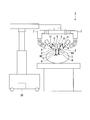
- FIG. 1 is a schematic overall view of the medical manipulator system of the present embodiment.
- FIG. 2 is a schematic diagram of a medical manipulator system.
- FIG. 3 is a block diagram of the medical manipulator system.
- FIG. 4 is a table showing control mode selection conditions in the medical manipulator system.
- the medical manipulator system 1 of the present embodiment includes a surgical instrument 2, an instrument holder 6, a base link 7, a link mechanism 8, a first operating unit 13, A second operation unit 21, a mode change input unit 22, and a control unit 30 are included.
- the medical manipulator system 1 includes a plurality of surgical instruments 2, a plurality of instrument holders 6 corresponding to each surgical instrument 2, and a plurality of link mechanisms 8.
- An endoscope may be attached to one or several of the plurality of instrument holders 6 instead of the surgical instrument 2.
- the surgical instrument 2 includes a shaft 3 that can be inserted into a body, an end effector 4 disposed at a distal end of the shaft 3, and a shaft 3 for operating the end effector 4. And a drive unit 5 disposed at the proximal end.
- the operation of the end effector 4 is controlled by the control unit 30 based on an operation on the first operation unit 13.
- a configuration of the end effector 4 of the present embodiment for example, a configuration of a known end effector 4 applied to laparoscopic surgery such as a grasping forceps or a knife may be appropriately selected.
- the instrument holder 6 is configured to be coupled to the surgical instrument 2.
- the drive unit 5 of the surgical instrument 2 can be attached to the instrument holder 6.
- the instrument holder 6 transmits a driving force for operating the end effector 4 to the drive unit 5 in accordance with control performed by the control unit 30 based on an operation input to the first operation unit 13.
- the base link 7 is configured to be held at a fixed position with respect to the patient.
- the base link 7 is disposed in the vicinity of the operating table.
- the link mechanism 8 couples the instrument holder 6 to the base link 7 with one or more degrees of freedom between the instrument holder 6 and the base link 7. Further, the link mechanism 8 links a joint (ordinary joint 9, see FIG. 3) that gives a degree of freedom necessary for moving the instrument holder 6 with respect to the base link 7, and a redundant degree of freedom exceeding this degree of freedom. A joint (redundant joint 10, see FIG. 3) to be provided to the mechanism 8 and a plurality of arms 11 connecting the joints are provided. Furthermore, the link mechanism 8 has a force sensor 12 (see FIG. 3) for detecting that the link mechanism 8 has come into contact with another object. The force sensor 12 of the link mechanism 8 is used, for example, to detect interference between a plurality of link mechanisms 8, contact or collision of the link mechanism 8 with a person, another medical device, or the like.
- the first operation unit 13 includes a monitor 14 for displaying an image of a treatment target region, and a master arm for operating the surgical instrument 2, the instrument holder 6, and the link mechanism 8. 15, a foot switch 16 for the surgeon to select whether or not each part can be operated based on the operation on the master arm 15, and a sensor for determining whether the surgeon is using the first operation part 13 17.
- the surgeon who uses the first operation unit 13 operates the foot switch 16 to permit the operation of each unit, and further operates the master arm 15 while viewing the image displayed on the monitor 14, thereby operating.
- the instrument 2, the instrument holder 6 and the link mechanism 8 can be remotely operated.
- the operations on the master arm 15 are an operation of moving the end effector 4 by restraining a part of the shaft 3 of the surgical instrument 2 as the remote center RC, and an end effector by restricting the position of the remote center RC and the position of the end effector 4. 4 to perform a treatment using 4.
- the first operation unit 13 issues an operation command to the control unit 30 based on the operation on the master arm 15.
- the sensor 17 included in the first operation unit 13 includes a first sensor 18 that detects whether or not the surgeon's head is positioned at an appropriate position for viewing the monitor 14, and the surgeon moves the master arm 15. It has the 2nd sensor 19 which detects whether it is operating, and the 3rd sensor 20 which detects the presence or absence of the input with respect to the foot switch 16.
- a first sensor 18 that detects whether or not the surgeon's head is positioned at an appropriate position for viewing the monitor 14, and the surgeon moves the master arm 15. It has the 2nd sensor 19 which detects whether it is operating, and the 3rd sensor 20 which detects the presence or absence of the input with respect to the foot switch 16.
- the second operation unit 21 shown in FIGS. 2 and 3 is an operation unit for operating the link mechanism 8.
- the second operation unit 21 in the present embodiment is set to a part of the outer surface of each arm 11 and each joint of the link mechanism 8.
- the 2nd operation part 21 is comprised by the site
- the operator (assistant) can push and pull each arm 11 and each joint of the link mechanism 8 directly to operate the link mechanism 8.
- the mode change input part 22 is provided in the site
- FIG. The mode change input unit 22 is used when an operator (assistant) performs an operation of pushing and pulling the second operation unit 21 directly. That is, the mode change input unit 22 is a switch for starting an operation for manually moving the link mechanism 8 for an assistant operating the second operation unit 21. In a state where it is not necessary for the assistant to manually change the position and posture of the link mechanism 8, no input to the mode change input unit 22 is performed. When the assistant needs to manually change the position and posture of the link mechanism 8, input to the mode change input unit 22 is performed by the assistant.
- the mode change input unit 22 of the present embodiment is a push button switch that is electrically connected to the control unit 30.
- the push button switch of the mode change input unit 22 is on while being pressed, and is turned off when the force of pressing the push button switch is eliminated.
- the medical manipulator system 1 of the present embodiment has a plurality of mode change input units 22 so that the mode change input units 22 are arranged one by one in the plurality of link mechanisms 8.
- a plurality of mode change input units 22 may be arranged in one link mechanism 8.
- the control unit 30 shown in FIGS. 1 to 3 controls the base link 7, the link mechanism 8, the instrument holder 6, and the surgical instrument 2 based on operations on the first operation unit 13 and the second operation unit 21. To do. As illustrated in FIG. 3, the control unit 30 includes a state acquisition unit 31, a control signal output unit 32, and a mode selection unit 33.
- the state acquisition unit 31 acquires the state of the medical manipulator system 1 with reference to various sensors 17 and the like.
- the state acquisition unit 31 refers to the sensor 17 disposed in the first operation unit 13 and acquires whether or not it is in an operation state using the first operation unit 13 as follows.
- the state acquisition unit 31 stores the state as being in operation using the first operation unit 13.
- the second sensor 19 detects the operation of the master arm 15
- the state acquisition unit 31 stores the state as being in an operation state using the first operation unit 13.
- the third sensor 20 detects that there is an input to the foot switch 16
- the state acquisition unit 31 stores the state as being in an operation state using the first operation unit 13. That is, the first sensor 18 does not detect the surgeon's head, the second sensor 19 does not detect the operation of the master arm 15, and the third sensor 20 does not detect the input to the foot switch 16.
- the state acquisition unit 31 stores the state as an operation using the first operation unit 13 is not performed.
- the state acquisition unit 31 stores that the first operation unit 13 is in an operating state. For this reason, in the case of performing a short break by simply releasing the hand from the master arm 15 or only stepping on the foot switch 16, the state of the first operation unit 13 becomes an operating state.
- the state acquisition unit 31 refers to the force sensor 12 disposed in the link mechanism 8 and acquires the state of presence / absence of interference between the plurality of link mechanisms 8.
- the state acquisition unit 31 of the present embodiment refers to the force sensor 12 disposed in the link mechanism 8 and acquires a state as to whether or not the link mechanism 8 has contacted another object.
- the state acquisition unit 31 stores the state as interference between the link mechanisms 8.
- the state acquisition unit 31 applies this link mechanism to another object that is not recognized by the medical manipulator system 1. The state is stored assuming that 8 has touched.
- the control signal output unit 32 outputs a control signal for operating the surgical instrument 2, the instrument holder 6, the base link 7, and the link mechanism 8 based on an operation command issued by the first operation unit 13. Output. Further, the control signal output unit 32 outputs a control signal for operating the link mechanism 8 based on an operation on the second operation unit 21.
- the control mode set in the control signal output unit 32 will be described.
- a plurality of control modes are set in the control signal output unit 32.
- the plurality of control modes are treatment modes (not shown) for outputting control signals to the surgical instrument 2, the instrument holder 6, the base link 7, and the link mechanism 8 based only on the operation command issued by the first operation unit 13.
- a control signal is output to the surgical instrument 2, the instrument holder 6, the base link 7, and the link mechanism 8 based on both the operation command issued by the first operation unit 13 and the operation on the second operation unit 21.
- Link adjustment mode (from the first mode to the fourth mode shown in FIG. 4).
- the treatment mode is a mode at the time of treatment in the operation of the medical manipulator system 1 (see FIGS. 1 to 3) of the present embodiment.
- the surgical instrument 2, the instrument holder 6, the base link 7, and the link mechanism 8 are automatically controlled in accordance with an operation performed by a surgeon (operator) who operates using the first operation unit 13.
- the mode selection unit 33 is selected. Selected by.
- the link adjustment mode is a mode for adjusting the position and posture of the link mechanism 8 when the medical manipulator system 1 of the present embodiment is used. Adjustment of the position and posture of the link mechanism 8 in the link adjustment mode is performed by an assistant (an operator different from the surgeon) who operates near the second operation unit 21. In the link adjustment mode, the link mechanism 8 operates according to the operation performed by the assistant on the second operation unit 21. In the link adjustment mode, as shown in FIG. 4, the position and posture of the link mechanism 8 are adjusted when the first operating unit 13 is in use, such as when the surgeon is performing treatment on the treatment target site. Modes (first mode and second mode) to be enabled and when the first operation unit 13 is not in use, the assistant freely operates the surgical instrument 2, the instrument holder 6, the base link 7, and the link mechanism 8. A mode that can be operated (third mode) and a mode (fourth mode) that prohibits the operation on the second operation unit 21.
- the first mode is a mode in which the position of the link mechanism 8 can be adjusted while performing treatment in a state where the position of the remote center RC (see FIG. 2) that is the center for swinging the surgical instrument 2 is fixed. That is, in the first mode, the surgical instrument 2 can be operated by the first operation unit 13 while the position of the remote center RC is fixed, and the operation of the first operation unit 13 and the operation of the surgical instrument 2 are performed.
- the link mechanism 8 can be moved by the second operation unit 21 while maintaining the correspondence.
- the position of the remote center RC in the first mode is the position of the trocar placed in the patient when the shaft 3 of the surgical instrument 2 is inserted into the patient's body (that is, the insertion point of the surgical instrument 2).
- the position of the remote center RC may be a desired position suitable for the operation.
- the shaft 3 In the first mode, the shaft 3 can be swung around the remote center RC. Further, in the first mode, the shaft 3 can be moved back and forth with respect to the trocar in a state where a part of the shaft 3 is located at the remote center RC. For this reason, in the first mode, it is possible to control the end effector 4 to move within the body.
- the first mode is used for positioning for placing the end effector 4 in the vicinity of the treatment target site.
- the second mode is a mode in which the position of the link mechanism 8 can be adjusted while performing the treatment while the position of the end effector 4 of the surgical instrument 2 is fixed. That is, in the second mode, the surgical instrument 2 can be operated by the first operation unit 13 with the position of the remote center RC and the position of the end effector 4 shown in FIG. The link mechanism 8 can be moved by the second operation unit 21 while maintaining the correspondence between the operation and the operation of the surgical instrument 2.
- the position of the end effector 4 is fixed in the body, and control of the distal end portion of the surgical instrument 2 such as swinging and opening / closing operation of the end effector 4 is possible.
- the second mode is used to operate the end effector 4 in order to treat the treatment target site after the position of the end effector 4 is determined in the first mode.
- one of the first mode and the second mode is automatically selected based on the operation performed by the surgeon on the first operation unit 13.
- the third mode illustrated in FIG. 4 is a mode in which the positional relationship among the surgical instrument 2, the instrument holder 6, the base link 7, and the link mechanism 8 illustrated in FIG. 2 can be changed only by an operation on the second operation unit 21. .
- the position of the remote center RC can be changed.
- the setting of the remote center RC is canceled and the surgical instrument 2, the instrument holder 6, the base link 7, and the link mechanism 8 are moved to desired positions, and each part has a desired positional relationship. After that, the remote center RC is reset based on the position of the trocar.
- the change of the position of the remote center RC means that the trocar is moved while the trocar is placed on the abdominal wall, or that the surgical instrument 2 is moved to a desired position in the case of open surgery.
- the third mode is used, for example, before the treatment is started or during the pause of the treatment in order to change the positional relationship of the surgical instrument 2, the instrument holder 6, the base link 7, and the link mechanism 8 as a whole.
- the operation by the second operation unit 21 is prohibited. That is, in the fourth mode, the link adjustment mode is turned off, and the surgical instrument 2, the link mechanism 8 and the like can be moved only by the first operation unit 13.
- the mode selection part 33 selects one mode from the 1st mode, the 2nd mode, the 3rd mode, and the 4th mode which are shown in FIG. 4 as a mode regarding the 2nd operation part 21.
- FIG. 5 is a flowchart illustrating an example of a control procedure in the control unit of the medical manipulator system.
- the control unit 30 selects one control mode while recognizing the state of the medical manipulator system 1 in real time by repeating a flow including the following steps S1 to S8.
- Step S ⁇ b> 1 is a first step for determining whether or not there is an input to the mode change input unit 22.
- step S1 if there is no input to the mode change input unit 22, the process proceeds to step S8 for selecting the fourth mode, and then returns to step S1 again. If an input to the mode change input unit 22 is detected in step S1, the process proceeds to step S2.
- Step S2 is a second step of acquiring the state of the medical manipulator system 1.
- the state acquisition unit 31 acquires and stores the state of the medical manipulator system 1.
- Step S2 is complete
- Step S3 is a step of determining whether or not the first operation unit 13 is in an operating state. In step S3, based on the state information stored by the state acquisition unit 31, if the first operation unit 13 is in the operating state, the process proceeds to step S4. If the first operation unit 13 is not in the operating state, step S3 is performed. Proceed to S7 to select the third mode.
- Step S4 determines whether the operation on the master arm 15 is an operation for restricting only the position of the remote center RC or an operation for restricting the position of the remote center RC and the position of the end effector 4. In step S4, based on the state information stored by the state acquisition unit 31, if the operation restricts only the position of the remote center RC, the process proceeds to step S5, the first mode is selected, and the position and end of the remote center RC are selected. If the operation restricts the position of the effector 4, the process proceeds to step S6 and the second mode is selected.
- each step shown from step S3 to step S8 constitutes a third step for selecting a suitable mode based on the state of the medical manipulator system 1.
- the link mechanism 8 of the medical manipulator system 1 of the present embodiment has the redundant joint 10 in addition to the regular joint 9, the surgical instrument 2 can be operated even if the link mechanism 8 is moved by the second operation unit 21. The position and posture are maintained. Furthermore, since the common joint 9 of the link mechanism 8 can be operated in accordance with the operation by the first operation unit 13 while the link mechanism 8 is being moved by the second operation unit 21, the surgeon can perform the treatment on the treatment target site, Operations such as positioning of the end effector 4 can be continued.
- the medical manipulator system 1 After the medical manipulator system 1 is activated, the medical manipulator system 1 operates in a predetermined initialization mode to set initial positions of the surgical instrument 2, the instrument holder 6, the base link 7, and the link mechanism 8 with respect to the patient. Do.
- This endoscope is held by the instrument holder 6 like the other surgical instruments 2, and is connected to the medical manipulator system 1 so as to display an image of the treatment target site on the monitor 14 of the first operation unit 13. Yes.
- the surgeon can operate the endoscope or the surgical instrument 2 by pressing the foot switch 16 while looking at the monitor 14.
- the sensor 17 provided in the first operation unit 13 detects that the surgeon's head is at the position of the monitor 14 and detects that there is an input to the foot switch 16. If the surgeon is operating the master arm 15, the sensor 17 detects that an operation is being performed on the master arm 15.
- the control unit 30 determines that the first operation unit 13 is operating in response to the detection results of the sensor 17 and receives an operation command for the first operation unit 13.
- the surgeon operates the endoscope and the surgical instrument 2 using the first operation unit 13, observes the treatment target region, and performs a treatment on the treatment target region as necessary.
- the surgeon operates the master arm 15 of the first operation unit 13 while looking at the monitor 14 and performs treatment on the treatment target region using the end effector 4. .
- no input is made to the mode change input unit 22 arranged in the second operation unit 21, so that the medical manipulator
- the system 1 operates in the treatment mode when the fourth mode is selected and the link adjustment mode is turned off.
- the assistant when moving the link mechanism 8, the assistant pushes and pulls the link mechanism 8 while pressing the mode change input unit 22 (push button switch) arranged in the link mechanism 8 to link to a desired position.
- the mechanism 8 is moved.
- the control unit 30 specifies the link mechanism 8 to change from the fourth mode to another mode, and unlocks the redundant joint 10 of the specified link mechanism 8. (End of the fourth mode).
- the common joint 9 of the link mechanism 8 operates in response to the operation by the first operation unit 13, and the redundant joint 10 of the link mechanism 8 follows the push and pull of the second operation unit 21. For example, a copying operation is performed.
- the control unit 30 operates in the first mode or the second mode, so that the position and posture of the link mechanism 8 can be set within the range of degrees of freedom given by the redundant joint 10 among all the degrees of freedom of the link mechanism 8.
- the assistant can change.
- the end of the operation on the second operation unit 21 is detected by the control unit 30 when the assistant operating the second operation unit 21 releases the push button switch of the mode change input unit 22.
- the mode selection unit 33 ends the first mode or the second mode, and shifts to the fourth mode.
- the control part 30 controls the base link 7, the link mechanism 8, the instrument holder 6, and the surgical instrument 2 according to the fourth mode.
- the control unit 30 prohibits the operation by the second operation unit 21. That is, the control unit 30 locks the redundant joint 10 when the fourth mode is selected.
- the treatment mode is set in which the base link 7, the link mechanism 8, the instrument holder 6, and the surgical instrument 2 are operated only by the operation by the first operation unit 13.
- a plurality of parts that are separated from each other may be the target of treatment.
- the positional relationship among the surgical instrument 2, the instrument holder 6, the base link 7, and the link mechanism 8 is entirely changed. There is a case.
- the surgeon pauses the operation on the first operation unit 13. That is, the surgeon releases his foot from the foot switch 16, releases his hand from the master arm 15, and further moves his head away from the monitor 14 of the first operation unit 13.
- the state acquisition unit 31 of the control unit 30 acquires and stores that the first operation unit is not in use.
- the mode selection unit 33 ends the fourth mode and selects the third mode.
- the control unit 30 is configured so that the surgical instrument 2, the instrument holder 6, the base link 7, and the common joint 9 and the redundant joint 10 of the link mechanism 8 can operate according to the operation on the second operation unit. Unlock the joints.
- the assistant operating the second operation unit 21 finishes the operation, the assistant releases the hand from the mode change input unit 22. Thereby, the third mode is ended in the mode selection unit 33 and the fourth mode is selected, and the control unit 30 performs the operation instrument 2, the instrument holder 6, the base link 7, and the common joint 9 of the link mechanism 8 and the redundancy.
- the joint of each part in the joint 10 is locked and the first operation unit 13 is in the operating state, the operation becomes possible according to the operation to the first operation unit 13.
- the medical manipulator system 1 corresponds to the state of the medical manipulator system 1 as long as the first operation unit 13 is in use.
- the mode change input unit 22 can be used for switching between the third mode and the fourth mode. If the first operation unit 13 is not in use, the mode change input unit 22 is used for switching between the third mode and the fourth mode. Is possible. That is, in the present embodiment, an appropriate mode can be selected from the four modes from the first mode to the fourth mode by selecting from two options using the mode change input unit 22. As a result, according to the medical manipulator system 1 of the present embodiment, an input operation for manually operating the link mechanism 8 can be easily performed.
- FIG. 6 is a flowchart illustrating an example of a control procedure in the control unit of the medical manipulator system of the present embodiment.
- the same components as those in the first embodiment are denoted by the same reference numerals as those in the first embodiment (see FIGS. 1 to 3), and redundant description is omitted.
- the medical manipulator system 1 of the present embodiment is different from the first embodiment when the link mechanisms 8 interfere with each other, or when the link mechanism 8 collides with other medical instruments or the like.
- the control unit 30 performs control.
- the state acquisition unit 31 acquires the interference between the link mechanisms 8 or the collision between the link mechanism 8 and another object based on the detection state of the force sensor 12.
- the control unit 30 determines that the interference is caused by the link mechanisms 8.
- the control unit 30 may specify interference between the link mechanisms 8 by using the positional relationship of the plurality of link mechanisms 8 and the detection result of the force sensor 12 together.
- the control unit 30 determines that the link mechanism 8 corresponding to the force sensor 12 It is determined that the object has collided with an object other than the link mechanism 8 (medical instrument, assistant body, etc.).
- the object other than the link mechanism 8 can be any object other than the object whose position is recognized in advance by the medical manipulator system 1 of the present embodiment and located within the movable range of the medical manipulator system 1. .
- the mode selection unit 33 specifies one mode from the first mode, the second mode, the third mode, and the fourth mode based on the acquisition status by the state acquisition unit 31.
- step S9 in which the process branches based on the presence or absence of interference or collision of the link mechanism 8 is included between step S3 and step S4 in the first embodiment.
- step S9 when the state acquisition part 31 has memorize
- the mode selection unit 33 proceeds to step S4 and performs the processing after step S4 as in the first embodiment. I do.
- the state acquisition unit 31 detects that there is interference or collision of the link mechanism 8
- an input to the mode change input unit 22 is made regardless of the operation state on the master arm 15. Then, the second mode is selected, and the assistant can use the second operation unit 21 to perform an operation for eliminating the interference and collision of the link mechanism 8.
- the operation in the first operation unit 13 is limited to the one that restricts the position of the end effector 4 (the posture and operation of the end effector 4 are not restricted). .
- the link mechanism 8 interferes and the second mode is selected while the treatment target site is being treated, the treatment is performed within the range in which the position of the end effector 4 is not changed. 13 can continue.
- the second mode is selected when the state acquisition unit 31 detects that there is an interference or a collision of the link mechanism 8, so that the swing operation about the remote center RC is performed. Since the operation of the link mechanism 8 does not occur, it is easy to operate the link mechanism 8 using the second operation unit.
- the position and posture of the surgical instrument 2 are fixed (only the end effector 4 is operable), and the normal joint 9 and the redundant joint 10 are Both may be operable by the second operation unit 21.
- the degree of freedom of the link mechanism 8 is further increased, interference and collision can be more easily resolved.
- the link mechanism 8 stops without being able to resolve the collision and interference in the second mode.
- the control in the third mode is performed in order to temporarily stop the treatment, quickly eliminate the interference and the collision, and restart the treatment.
- the third mode is selected when the first operation unit 13 is not in the operating state in step S3.
- the link mechanism 8 when interference or collision occurs in the link mechanism 8, the link mechanism 8 is manually operated while increasing the possibility of continuing treatment.
- the input operation for making it possible can be performed easily.
- the fourth mechanism is set so that the link mechanism 8 shifts to the third mode in which it can move with a higher degree of freedom than the second mode.
- the mode selection unit 33 automatically sets a mode to be switched from the mode. For this reason, even when complicated interference between the link mechanisms 8 occurs, an input operation for manually operating the link mechanism 8 can be easily performed.
- the third mode is selected in the present embodiment, it is not limited to the case where there is interference or collision of the link mechanism 8, and the treatment target site is moved from one treatment target site as in the first embodiment. You may change to other treatment object site
- the present invention can be used for a manipulator having a link mechanism.
Abstract
Description
特許文献1に開示された医療用マニピュレータシステムは、遠隔中心の位置を維持しながらアームのリンク機構を自動又は手動で移動させることができる。
本発明は、上述した事情に鑑みてなされたものであって、リンク機構を手動で動作させるための入力操作を簡便に行うことができる医療用マニピュレータシステムを提供することを目的とする。
本発明の第1実施形態について説明する。図1は、本実施形態の医療用マニピュレータシステムの模式的な全体図である。図2は、医療用マニピュレータシステムの模式図である。図3は、医療用マニピュレータシステムのブロック図である。図4は、医療用マニピュレータシステムにおける制御モードの選択条件を示す表である。
エンドエフェクタ4の動作は、第1の操作部13に対する操作に基づいて、制御部30によって制御される。本実施形態のエンドエフェクタ4の構成として、例えば把持鉗子やナイフ等、腹腔鏡手術に適用される公知のエンドエフェクタ4の構成が適宜選択されてよい。
さらに、リンク機構8は、リンク機構8が他の物体に接触したことを検知するための力覚センサ12(図3参照)を有している。リンク機構8の力覚センサ12は、例えば、複数のリンク機構8同士の干渉や、人や他の医療機器等に対するリンク機構8の接触や衝突等を検知するために使用される。
図3に示すように、制御部30は、状態取得部31と、制御信号出力部32と、モード選択部33とを有している。
第一センサ18が執刀医の頭部を検知している場合には、状態取得部31は、第1の操作部13を用いた操作中状態であるとして状態を記憶する。
第二センサ19がマスタアーム15の操作を検知している場合には、状態取得部31は、第1の操作部13を用いた操作中状態であるとして状態を記憶する。
第三センサ20がフットスイッチ16に対する入力があることを検知している場合には、状態取得部31は、第1の操作部13を用いた操作中状態であるとして状態を記憶する。
すなわち、第一センサ18に執刀医の頭部が検知されず、且つ、第二センサ19にマスタアーム15の操作が検知されず、且つ、第三センサ20にフットスイッチ16に対する入力が検知されない場合に、状態取得部31は第1の操作部13を用いた操作が行われていないとして状態を記憶する。
本実施形態では、複数のリンク機構8の力覚センサ12に同時に入力がある場合には、状態取得部31が、リンク機構8同士の干渉であるとして状態を記憶する。
また、移動中の1つのリンク機構8の力覚センサ12が他の物体に対する接触を検知した場合には、状態取得部31が、医療用マニピュレータシステム1の認識外の他の物体にこのリンク機構8が接触したとして状態を記憶する。
制御信号出力部32には、複数の制御モードが設定されている。複数の制御モードは、第1の操作部13が発する操作指令のみに基づいて手術器具2、器具ホルダ6、ベースリンク7、及びリンク機構8に対して制御信号を出力する処置モード(不図示)と、第1の操作部13が発する操作指令と第2の操作部21に対する操作との両方に基づいて手術器具2、器具ホルダ6、ベースリンク7、及びリンク機構8に対して制御信号を出力するリンク調整モード(図4に示す第一モードから第四モードまで)とを有している。
リンク調整モードは、図4に示すように、執刀医が処置対象部位に対して処置を行っているなど第1の操作部13の使用中状態である場合にリンク機構8の位置及び姿勢を調整可能とするモード(第一モード及び第二モード)と、第1の操作部13の使用中状態でない場合に手術器具2、器具ホルダ6、ベースリンク7、及びリンク機構8を助手が自在に動作させることできるモード(第三モード)と、第2の操作部21に対する操作を禁止するモード(第四モード)とを含む。
第三モードは、手術器具2、器具ホルダ6、ベースリンク7、及びリンク機構8の位置関係を全体的に変更するために、たとえば処置開始前や処置の休止中に利用される。
制御部30は、以下のステップS1からステップS8までの各ステップを含むフローを繰り返すことにより、医療用マニピュレータシステム1の状態をリアルタイムで把握しながら、1つの制御モードを選択する。
ステップS2は、医療用マニピュレータシステム1の状態を取得する第二ステップである。ステップS2では、状態取得部31が医療用マニピュレータシステム1の状態を取得して記憶する。これでステップS2は終了し、ステップS3へ進む。
医療用マニピュレータシステム1の起動後、医療用マニピュレータシステム1は、所定のイニシャライズモードで動作して、患者に対して手術器具2、器具ホルダ6、ベースリンク7、及びリンク機構8の初期位置設定を行う。
処置対象部位に対して処置を行う場合には、執刀医は、モニタ14を見ながら第1の操作部13のマスタアーム15を動作させて、エンドエフェクタ4を用いて処置対象部位の処置を行う。このとき、リンク機構8の位置や姿勢を助手が手動で変化させる必要がない状態では、第2の操作部21に配されたモード変更入力部22には入力がされていないので、医療用マニピュレータシステム1は第四モードが選択されてリンク調整モードがオフとなり、処置モードで動作する。
本発明の第2実施形態について説明する。図6は、本実施形態の医療用マニピュレータシステムの制御部における制御手順の一例を示すフローチャートである。なお、本実施形態において上記第1実施形態と共通の構成要素には、第1実施形態と同一の符号(図1から図3までを参照)が付され、重複する説明は省略される。
本実施形態では、第1実施形態におけるステップS3とステップS4との間に、リンク機構8の干渉又は衝突の有無に基づいて処理の分岐するステップS9を含む。
ステップS9では、リンク機構8の干渉や衝突があると状態取得部31が記憶している場合には、ステップS6へ進んで第二モードが選択される。ステップS9では、リンク機構8の干渉や衝突がないと状態取得部31が記憶している場合には、モード選択部33は、ステップS4へ進んで第1実施形態と同様にステップS4以降の処理を行う。
また、上述の各実施形態において示した構成要素は適宜に組み合わせて構成することが可能である。
2 手術器具
3 シャフト
4 エンドエフェクタ
5 駆動部
6 器具ホルダ
7 ベースリンク
8 リンク機構
9 常用関節
10 冗長関節
11 アーム
12 力覚センサ
13 第1の操作部
14 モニタ
15 マスタアーム
16 フットスイッチ
17 センサ
18 第一センサ
19 第二センサ
20 第三センサ
21 第2の操作部
22 モード変更入力部
30 制御部
31 状態取得部
32 制御信号出力部
33 モード選択部
Claims (6)
- 医療用マニピュレータシステムであって、
エンドエフェクタを有する手術器具と、
前記手術器具と結合するように構成される器具ホルダと、
患者に対して固定位置に保持されるように構成されるベースリンクと、
前記器具ホルダを前記ベースリンクに結合するリンク機構と、
前記手術器具、前記器具ホルダおよび前記リンク機構を操作するための第1の操作部と、
前記リンク機構を操作するための第2の操作部と、
複数の制御モードから1つを選択し選択された制御モードに従って前記リンク機構を制御する制御部と、
前記制御部に選択されているモードから前記複数の制御モードのうちの他のモードへ変更する入力を受け付けるために前記第2の操作部に設けられたモード変更入力部と、
を有し、
前記制御部は、前記リンク機構を制御するための制御手順として、
前記モード変更入力部に対する入力の有無を判定する第一ステップと、
前記第一ステップの後、前記医療用マニピュレータシステムの状態を取得する第二ステップと、
前記第二ステップの後、前記医療用マニピュレータシステムの状態に基づいて前記複数の制御モードのうち前記状態に適合するモードを選択する第三ステップと、
を含み、前記制御手順に従って前記リンク機構を制御する
ことを特徴とする医療用マニピュレータシステム。 - 前記複数の制御モードは、
前記手術器具を揺動動作させる中心となる遠隔中心の位置を固定した状態で前記第1の操作部の操作と前記手術器具の動作との対応関係を維持したまま前記第2の操作部により前記リンク機構を移動可能とする第一モードと、
前記遠隔中心の位置及び前記エンドエフェクタの位置を固定した状態で前記第1の操作部の操作と前記手術器具の動作との対応関係を維持したまま前記第2の操作部により前記リンク機構を移動可能とする第二モードと、
前記第2の操作部により前記手術器具及び前記リンク機構を移動可能とする第三モードと、
前記第2の操作部による操作を禁止して前記第1の操作部のみで前記手術器具及び前記リンク機構を移動可能とする第四モードと、
を有する請求項1に記載の医療用マニピュレータシステム。 - 前記制御部は、前記モード変更入力部に対する入力の有無に対応して、前記第一モード,前記第二モード,及び前記第三モードのうちのいずれか1つと、前記第四モードとを相互に切り替える。
請求項2に記載の医療用マニピュレータシステム。 - 前記制御部は、前記第1の操作部による操作中状態であるか否かを前記第三ステップにおいて判定し、
前記状態が前記第1の操作部による操作中状態であると前記制御部が判定した場合には、前記制御部は、前記モード変更入力部に対する入力操作が行われていない場合には前記第四モードを選択し、前記モード変更入力部に対する入力操作が行われている間は前記第一モードと前記第二モードとのいずれか一方を選択する
請求項3に記載の医療用マニピュレータシステム。 - 前記制御部は、前記リンク機構と他の物体との干渉又は衝突の有無を前記第三ステップにおいて判定し、
前記状態が前記リンク機構と他の物体とが干渉または衝突している状態であると前記制御部が判定した場合には、前記制御部は、前記モード変更入力部に対する入力操作が行われていない場合には前記第四モードを選択し、前記モード変更入力部に対する入力操作が行われている間は前記第二モードを選択し、
前記状態が前記リンク機構と他の物体とが干渉していない状態であると前記制御部が判定した場合には、前記制御部は、前記モード変更入力部に対する入力操作が行われていない場合には前記第四モードを選択し、前記モード変更入力部に対する入力操作が行われている間は前記第一モードを選択する
請求項3に記載の医療用マニピュレータシステム。 - 前記リンク機構は少なくとも1以上の冗長関節を有し、
前記第2の操作部は、前記冗長関節のみを操作可能である
請求項1から5のいずれか一項に記載の医療用マニピュレータシステム。
Priority Applications (5)
| Application Number | Priority Date | Filing Date | Title |
|---|---|---|---|
| EP16886317.3A EP3406220A4 (en) | 2016-01-21 | 2016-01-21 | MEDICAL MANIPULATOR SYSTEM |
| JP2017513568A JP6157785B1 (ja) | 2016-01-21 | 2016-01-21 | 医療用マニピュレータシステム |
| CN201680066039.0A CN108348298B (zh) | 2016-01-21 | 2016-01-21 | 医疗用机械手系统 |
| PCT/JP2016/051672 WO2017126076A1 (ja) | 2016-01-21 | 2016-01-21 | 医療用マニピュレータシステム |
| US15/976,099 US10646296B2 (en) | 2016-01-21 | 2018-05-10 | Medical manipulator system, controller, and computer-readable storage device |
Applications Claiming Priority (1)
| Application Number | Priority Date | Filing Date | Title |
|---|---|---|---|
| PCT/JP2016/051672 WO2017126076A1 (ja) | 2016-01-21 | 2016-01-21 | 医療用マニピュレータシステム |
Related Child Applications (1)
| Application Number | Title | Priority Date | Filing Date |
|---|---|---|---|
| US15/976,099 Continuation US10646296B2 (en) | 2016-01-21 | 2018-05-10 | Medical manipulator system, controller, and computer-readable storage device |
Publications (1)
| Publication Number | Publication Date |
|---|---|
| WO2017126076A1 true WO2017126076A1 (ja) | 2017-07-27 |
Family
ID=59272967
Family Applications (1)
| Application Number | Title | Priority Date | Filing Date |
|---|---|---|---|
| PCT/JP2016/051672 WO2017126076A1 (ja) | 2016-01-21 | 2016-01-21 | 医療用マニピュレータシステム |
Country Status (5)
| Country | Link |
|---|---|
| US (1) | US10646296B2 (ja) |
| EP (1) | EP3406220A4 (ja) |
| JP (1) | JP6157785B1 (ja) |
| CN (1) | CN108348298B (ja) |
| WO (1) | WO2017126076A1 (ja) |
Families Citing this family (4)
| Publication number | Priority date | Publication date | Assignee | Title |
|---|---|---|---|---|
| DE102016221222A1 (de) * | 2016-10-27 | 2018-05-03 | Siemens Healthcare Gmbh | Verfahren zum Betrieb eines Kollisionsschutzsystems für eine medizinische Operationseinrichtung, medizinische Operationseinrichtung, Computerprogramm und Datenträger |
| WO2022063214A1 (zh) * | 2020-09-25 | 2022-03-31 | 武汉联影智融医疗科技有限公司 | 手术机器人控制方法、计算机设备及手术机器人系统 |
| CN113276111A (zh) * | 2021-04-30 | 2021-08-20 | 武汉联影智融医疗科技有限公司 | 手术机器人控制系统、控制方法 |
| CN112957008A (zh) * | 2021-01-29 | 2021-06-15 | 海南省妇女儿童医学中心 | 一种远程触诊设备 |
Citations (4)
| Publication number | Priority date | Publication date | Assignee | Title |
|---|---|---|---|---|
| WO2006124390A2 (en) * | 2005-05-19 | 2006-11-23 | Intuitive Surgical, Inc | Software center and highly configurable robotic systems for surgery and other uses |
| JP2009520573A (ja) * | 2005-12-20 | 2009-05-28 | インテュイティブ サージカル インコーポレイテッド | ロボット手術システムの機器インターフェース |
| JP2013510632A (ja) * | 2009-11-16 | 2013-03-28 | コーニンクレッカ フィリップス エレクトロニクス エヌ ヴィ | 内視鏡支援ロボットのための人‐ロボット共用制御 |
| US20130325031A1 (en) | 2012-06-01 | 2013-12-05 | Intuitive Surgical Operations, Inc. | Redundant axis and degree of freedom for hardware-constrained remote center robotic manipulator |
Family Cites Families (10)
| Publication number | Priority date | Publication date | Assignee | Title |
|---|---|---|---|---|
| US6659939B2 (en) * | 1998-11-20 | 2003-12-09 | Intuitive Surgical, Inc. | Cooperative minimally invasive telesurgical system |
| JP5571432B2 (ja) | 2010-03-30 | 2014-08-13 | カール シュトルツ ゲゼルシャフト ミット ベシュレンクテル ハフツング ウント コンパニー コマンディートゲゼルシャフト | 医療用ロボットシステム |
| JP5800616B2 (ja) * | 2011-07-15 | 2015-10-28 | オリンパス株式会社 | マニピュレータシステム |
| JP6021353B2 (ja) * | 2011-08-04 | 2016-11-09 | オリンパス株式会社 | 手術支援装置 |
| US9259281B2 (en) * | 2012-08-15 | 2016-02-16 | Intuitive Surgical Operations, Inc. | Movable surgical mounting platform controlled by manual motion of robotic arms |
| CN105101903B (zh) * | 2013-02-04 | 2018-08-24 | 儿童国家医疗中心 | 混合控制外科机器人系统 |
| WO2014146113A1 (en) * | 2013-03-15 | 2014-09-18 | Intuitive Surgical Operations, Inc. | Systems and methods for tracking a path using the null-space |
| JP2014204794A (ja) | 2013-04-11 | 2014-10-30 | 株式会社デンソー | 身体支持追従装置用状態表示装置及び身体支持追従装置 |
| JP6173089B2 (ja) | 2013-07-24 | 2017-08-02 | オリンパス株式会社 | 医療用マスタースレーブシステムの制御方法 |
| CN107847285B (zh) * | 2015-07-23 | 2020-09-08 | 奥林巴斯株式会社 | 输入机构和医疗系统 |
-
2016
- 2016-01-21 WO PCT/JP2016/051672 patent/WO2017126076A1/ja active Application Filing
- 2016-01-21 JP JP2017513568A patent/JP6157785B1/ja active Active
- 2016-01-21 EP EP16886317.3A patent/EP3406220A4/en not_active Withdrawn
- 2016-01-21 CN CN201680066039.0A patent/CN108348298B/zh active Active
-
2018
- 2018-05-10 US US15/976,099 patent/US10646296B2/en active Active
Patent Citations (4)
| Publication number | Priority date | Publication date | Assignee | Title |
|---|---|---|---|---|
| WO2006124390A2 (en) * | 2005-05-19 | 2006-11-23 | Intuitive Surgical, Inc | Software center and highly configurable robotic systems for surgery and other uses |
| JP2009520573A (ja) * | 2005-12-20 | 2009-05-28 | インテュイティブ サージカル インコーポレイテッド | ロボット手術システムの機器インターフェース |
| JP2013510632A (ja) * | 2009-11-16 | 2013-03-28 | コーニンクレッカ フィリップス エレクトロニクス エヌ ヴィ | 内視鏡支援ロボットのための人‐ロボット共用制御 |
| US20130325031A1 (en) | 2012-06-01 | 2013-12-05 | Intuitive Surgical Operations, Inc. | Redundant axis and degree of freedom for hardware-constrained remote center robotic manipulator |
Non-Patent Citations (1)
| Title |
|---|
| See also references of EP3406220A4 * |
Also Published As
| Publication number | Publication date |
|---|---|
| JPWO2017126076A1 (ja) | 2018-01-25 |
| CN108348298A (zh) | 2018-07-31 |
| CN108348298B (zh) | 2021-05-14 |
| US10646296B2 (en) | 2020-05-12 |
| EP3406220A4 (en) | 2019-09-18 |
| JP6157785B1 (ja) | 2017-07-05 |
| EP3406220A1 (en) | 2018-11-28 |
| US20180256273A1 (en) | 2018-09-13 |
Similar Documents
| Publication | Publication Date | Title |
|---|---|---|
| JP7260479B2 (ja) | 外科用器具の動作制御を調整するための制御システム | |
| JP7275204B2 (ja) | 遠隔操作医療システムにおけるオンスクリーンメニューのためのシステム及び方法 | |
| JP6157785B1 (ja) | 医療用マニピュレータシステム | |
| US11141231B2 (en) | Surgical tool performance via measurement and display of tissue tension | |
| JP2018538036A (ja) | 再構成可能なエンドエフェクタのアーキテクチャ | |
| EP2713922A1 (en) | Positive control of robotic surgical instrument end effector | |
| US10548677B2 (en) | Medical manipulator system, control device of medical manipulator system, and control method of medical manipulator system | |
| JP7411804B2 (ja) | 外科手術器具の制御 | |
| JP2023504725A (ja) | 外科手術用アームを制御するためのユーザ入力デバイスの向き | |
| US20130103199A1 (en) | Surgical robot control apparatus | |
| US11324561B2 (en) | Remote manipulator system and method for operating a remote manipulator system | |
| US20210298753A1 (en) | Anastomosis device | |
| JP7463615B2 (ja) | 副ロボットコントローラに制御を移行するための外科用ロボットシステム及び方法 | |
| JP7330543B2 (ja) | 着用可能な手術用ロボットアーム | |
| US10918451B2 (en) | Medical instrument holding device, medical system, operating method of medical instrument holding device, and operating method of medical system | |
| JPH08280695A (ja) | 手術用マニピュレータ装置 | |
| KR20110012822A (ko) | 수술용 로봇 | |
| CN116869668B (zh) | 手术机器人系统 | |
| US20210353328A1 (en) | Surgical system use flow and tools | |
| WO2023026074A1 (en) | Imaging device with elongate arm and pivotable camera | |
| CN114652447A (zh) | 机器人手术系统和用于控制机器人手术系统的方法 | |
| Cadière et al. | Telerobotic-Assisted Antireflux Surgery: Nissen Fundoplication |
Legal Events
| Date | Code | Title | Description |
|---|---|---|---|
| ENP | Entry into the national phase |
Ref document number: 2017513568 Country of ref document: JP Kind code of ref document: A |
|
| 121 | Ep: the epo has been informed by wipo that ep was designated in this application |
Ref document number: 16886317 Country of ref document: EP Kind code of ref document: A1 |
|
| NENP | Non-entry into the national phase |
Ref country code: DE |
|
| WWE | Wipo information: entry into national phase |
Ref document number: 2016886317 Country of ref document: EP |
|
| ENP | Entry into the national phase |
Ref document number: 2016886317 Country of ref document: EP Effective date: 20180821 |