US11090126B2 - Input device handle for robotic surgical systems capable of large rotations about a roll axis - Google Patents
Input device handle for robotic surgical systems capable of large rotations about a roll axis Download PDFInfo
- Publication number
- US11090126B2 US11090126B2 US16/081,728 US201716081728A US11090126B2 US 11090126 B2 US11090126 B2 US 11090126B2 US 201716081728 A US201716081728 A US 201716081728A US 11090126 B2 US11090126 B2 US 11090126B2
- Authority
- US
- United States
- Prior art keywords
- tool
- input device
- cylinder
- device handle
- roll axis
- Prior art date
- Legal status (The legal status is an assumption and is not a legal conclusion. Google has not performed a legal analysis and makes no representation as to the accuracy of the status listed.)
- Active, expires
Links
- 238000003384 imaging method Methods 0.000 description 13
- 230000033001 locomotion Effects 0.000 description 9
- 239000012636 effector Substances 0.000 description 8
- 238000000034 method Methods 0.000 description 8
- 238000001356 surgical procedure Methods 0.000 description 7
- 238000004891 communication Methods 0.000 description 6
- 238000005096 rolling process Methods 0.000 description 4
- 230000008878 coupling Effects 0.000 description 3
- 238000010168 coupling process Methods 0.000 description 3
- 238000005859 coupling reaction Methods 0.000 description 3
- 230000007935 neutral effect Effects 0.000 description 2
- 210000003813 thumb Anatomy 0.000 description 2
- 230000000007 visual effect Effects 0.000 description 2
- 230000008901 benefit Effects 0.000 description 1
- 238000010276 construction Methods 0.000 description 1
- 210000003811 finger Anatomy 0.000 description 1
- 230000005484 gravity Effects 0.000 description 1
- 210000004247 hand Anatomy 0.000 description 1
- 238000012986 modification Methods 0.000 description 1
- 230000004048 modification Effects 0.000 description 1
- 230000004044 response Effects 0.000 description 1
- 238000002604 ultrasonography Methods 0.000 description 1
Images


Classifications
-
- A—HUMAN NECESSITIES
- A61—MEDICAL OR VETERINARY SCIENCE; HYGIENE
- A61B—DIAGNOSIS; SURGERY; IDENTIFICATION
- A61B34/00—Computer-aided surgery; Manipulators or robots specially adapted for use in surgery
- A61B34/70—Manipulators specially adapted for use in surgery
- A61B34/74—Manipulators with manual electric input means
-
- A—HUMAN NECESSITIES
- A61—MEDICAL OR VETERINARY SCIENCE; HYGIENE
- A61B—DIAGNOSIS; SURGERY; IDENTIFICATION
- A61B17/00—Surgical instruments, devices or methods
-
- A—HUMAN NECESSITIES
- A61—MEDICAL OR VETERINARY SCIENCE; HYGIENE
- A61B—DIAGNOSIS; SURGERY; IDENTIFICATION
- A61B17/00—Surgical instruments, devices or methods
- A61B17/28—Surgical forceps
- A61B17/29—Forceps for use in minimally invasive surgery
-
- A—HUMAN NECESSITIES
- A61—MEDICAL OR VETERINARY SCIENCE; HYGIENE
- A61B—DIAGNOSIS; SURGERY; IDENTIFICATION
- A61B34/00—Computer-aided surgery; Manipulators or robots specially adapted for use in surgery
- A61B34/30—Surgical robots
- A61B34/35—Surgical robots for telesurgery
-
- A—HUMAN NECESSITIES
- A61—MEDICAL OR VETERINARY SCIENCE; HYGIENE
- A61B—DIAGNOSIS; SURGERY; IDENTIFICATION
- A61B34/00—Computer-aided surgery; Manipulators or robots specially adapted for use in surgery
- A61B34/30—Surgical robots
- A61B34/37—Leader-follower robots
-
- A—HUMAN NECESSITIES
- A61—MEDICAL OR VETERINARY SCIENCE; HYGIENE
- A61B—DIAGNOSIS; SURGERY; IDENTIFICATION
- A61B34/00—Computer-aided surgery; Manipulators or robots specially adapted for use in surgery
- A61B34/70—Manipulators specially adapted for use in surgery
-
- A—HUMAN NECESSITIES
- A61—MEDICAL OR VETERINARY SCIENCE; HYGIENE
- A61B—DIAGNOSIS; SURGERY; IDENTIFICATION
- A61B34/00—Computer-aided surgery; Manipulators or robots specially adapted for use in surgery
- A61B34/70—Manipulators specially adapted for use in surgery
- A61B34/77—Manipulators with motion or force scaling
-
- A—HUMAN NECESSITIES
- A61—MEDICAL OR VETERINARY SCIENCE; HYGIENE
- A61B—DIAGNOSIS; SURGERY; IDENTIFICATION
- A61B17/00—Surgical instruments, devices or methods
- A61B2017/00367—Details of actuation of instruments, e.g. relations between pushing buttons, or the like, and activation of the tool, working tip, or the like
- A61B2017/00389—Button or wheel for performing multiple functions, e.g. rotation of shaft and end effector
-
- A—HUMAN NECESSITIES
- A61—MEDICAL OR VETERINARY SCIENCE; HYGIENE
- A61B—DIAGNOSIS; SURGERY; IDENTIFICATION
- A61B34/00—Computer-aided surgery; Manipulators or robots specially adapted for use in surgery
- A61B34/30—Surgical robots
- A61B2034/301—Surgical robots for introducing or steering flexible instruments inserted into the body, e.g. catheters or endoscopes
-
- A—HUMAN NECESSITIES
- A61—MEDICAL OR VETERINARY SCIENCE; HYGIENE
- A61B—DIAGNOSIS; SURGERY; IDENTIFICATION
- A61B34/00—Computer-aided surgery; Manipulators or robots specially adapted for use in surgery
- A61B34/30—Surgical robots
- A61B2034/302—Surgical robots specifically adapted for manipulations within body cavities, e.g. within abdominal or thoracic cavities
-
- A—HUMAN NECESSITIES
- A61—MEDICAL OR VETERINARY SCIENCE; HYGIENE
- A61B—DIAGNOSIS; SURGERY; IDENTIFICATION
- A61B34/00—Computer-aided surgery; Manipulators or robots specially adapted for use in surgery
- A61B34/30—Surgical robots
- A61B2034/305—Details of wrist mechanisms at distal ends of robotic arms
-
- A—HUMAN NECESSITIES
- A61—MEDICAL OR VETERINARY SCIENCE; HYGIENE
- A61B—DIAGNOSIS; SURGERY; IDENTIFICATION
- A61B34/00—Computer-aided surgery; Manipulators or robots specially adapted for use in surgery
- A61B34/70—Manipulators specially adapted for use in surgery
- A61B34/74—Manipulators with manual electric input means
- A61B2034/742—Joysticks
Definitions
- Robotic surgical systems have been used in minimally invasive medical procedures.
- the robotic surgical system is controlled by a surgeon interfacing with a user interface.
- the user interface allows the surgeon to manipulate an end effector that acts on a patient.
- the user interface includes an input controller or handle that is moveable by the surgeon to control the robotic surgical system.
- Robotic surgical systems typically used a scaling factor to scale down the motions of the surgeon's hands to determine the desired position of the end effector within the patient so that the surgeon could more precisely move the end effector inside the patient.
- the larger the scaling factor the farther the surgeon had to move the input device handle to move the end effector the same distance. Since the input device handle has a fixed range of motion, this meant that for larger scaling factors the surgeon may have reached an end of the range of motion of an input handle more often.
- a surgeon may need to rotate the end effector about a roll axis.
- large rotations of an end effector may be required.
- Such large rotations typically require multiple clutching events of an input device handle or unnatural rotations of the input device handle.
- This disclosure generally relates to an input device handle including a body and a cylinder that is rotatable relative to the body. Rotation of the cylinder is configured to affect rotation of the tool such that the tool can be rotating without rolling of the arm of the clinician. By allowing the tool to be rotated without rolling the arm of the clinician, the tool can be continuously rolled without clutching of the user interface or being limited by anatomical limits of the clinician.
- an input device handle for controlling a robot includes a body and a cylinder.
- the body defines an opening that rotatably receives the cylinder.
- the cylinder defines a roll axis such that rotation of the cylinder relative to the body about the roll axis is configured to rotate a tool of the robot about a first axis that is defined by the tool.
- the rotation of the cylinder about the roll axis may be scaled to rotation of the tool about the first axis.
- the cylinder frictionally engages the body such that as the body is rotated about the roll axis, the cylinder is rotated about the roll axis.
- Rotation of the body about the roll axis may be configured to rotate the tool of the robot about the first axis.
- rotation of the body about the roll axis may be configured to rotate a shaft supporting the tool about a second axis that is defined by the shaft.
- the first and second axis may be coincident with one another.
- the cylinder includes an engagement feature.
- the engagement feature may be alternating ribs and recesses. Additionally or alternatively, the engagement feature may be a textured surface.
- a robotic system in another aspect of the present disclosure, includes a robot and a user interface.
- the robot includes an arm and a tool that is support at the end of the arm.
- the tool defines a first axis.
- the user interface is in operable communication with the robot to control the tool.
- the user interface includes a control arm, a gimbal, and an input shaft.
- the gimbal is supported by the control arm and has an input shaft.
- the input device handle is coupled to the input shaft and defines a roll axis.
- the input device handle includes a body and a cylinder.
- the body defines an opening that rotatably receives the cylinder.
- the cylinder is disposed within the opening defined in the body and is rotatable about a roll axis such that rotation of the cylinder relative to the body about the roll axis rotates the tool about the first axis.
- the robot includes a shaft that supports the tool and defines a second axis. Rotation of the body about the tool axis may rotate the shaft about the second axis.
- the gimbal includes a first sensor that is configured to detect rotation of the input shaft relative to the gimbal.
- the first sensor can be disposed within the input shaft.
- the input device handle can include a second sensor that is configured to detect rotation of the cylinder relative to the body.
- the method further includes rotating the body about the roll axis to rotate the tool about the first axis.
- the method may include rotating the body about the roll axis to rotate a shaft that supports the tool about a second axis defined by the shaft.
- the method may include articulating the tool relative to the shaft before rotating the cylinder. Articulating the tool relative to the shaft may include articulating the first axis relative to the second axis.
- FIG. 1 is a schematic illustration of a user interface and a robotic system in accordance with the present disclosure
- FIG. 2 is a perspective view of a input device handle supported on an end of a control arm of the user interface of FIG. 1 ;
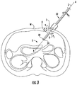
- FIG. 3 is a cutaway view of a body cavity of a patient showing a tool of the robotic surgical system of FIG. 1 inserted in the body cavity;
- FIG. 4 is a side perspective view of the input device handle of FIG. 2 ;
- FIG. 5 is a perspective view of the tool of FIG. 3 .
- the term “clinician” refers to a doctor, a nurse, or any other care provider and may include support personnel.
- proximal refers to the portion of the device or component thereof that is closest to the clinician and the term “distal” refers to the portion of the device or component thereof that is farthest from the clinician.
- neutral is understood to mean non-scaled.
- the input device handle includes a rotation control that is associated with one or more roll axes of a tool of the robotic system.
- the rotation control includes a cylinder capable of rotation about a roll axis of a gimbal of the user interface relative to a body of the input device handle.
- the cylinder may be associated with rotation of the tool about a tool axis defined between jaws of the tool.
- rotation of the body of the input device handle about the roll axis of the gimbal may be associated with rotation about the tool axis.
- the tool may be articulated relative to a shaft supporting the tool and rotation of the body of the input device handle about the roll axis of the gimbal may be associated with rotation about a shaft axis defined by the shaft.
- a robotic surgical system 1 in accordance with the present disclosure is shown generally as a robotic system 10 , a processing unit 30 , and a user interface 40 .
- the robotic system 10 generally includes linkages 12 and a robot base 18 .
- the linkages 12 moveably support an end effector or tool 20 which is configured to act on tissue.
- the linkages 12 may be in the form of arms each having an end 14 that supports an end effector or tool 20 which is configured to act on tissue.
- the ends 14 of the arms 12 may include an imaging device 16 for imaging a surgical site “S”.
- the user interface 40 is in communication with robot base 18 through the processing unit 30 .
- the user interface 40 includes a display device 44 which is configured to display three-dimensional images.
- the display device 44 displays three-dimensional images of the surgical site “S” which may include data captured by imaging devices 16 positioned on the ends 14 of the arms 12 and/or include data captured by imaging devices that are positioned about the surgical theater (e.g., an imaging device positioned within the surgical site “S”, an imaging device positioned adjacent the patient “P”, imaging device 56 positioned at a distal end of an imaging arm 52 ).
- the imaging devices e.g., imaging devices 16 , 56
- the imaging devices may capture visual images, infra-red images, ultrasound images, X-ray images, thermal images, and/or any other known real-time images of the surgical site “S”.
- the imaging devices transmit captured imaging data to the processing unit 30 which creates three-dimensional images of the surgical site “S” in real-time from the imaging data and transmits the three-dimensional images to the display device 44 for display.
- the user interface 40 also includes gimbals 42 which are supported on control arms 43 which allow a clinician to manipulate the robotic system 10 (e.g., move the arms 12 , the ends 14 of the arms 12 , and/or the tools 20 ).
- Each of the gimbals 42 is in communication with the processing unit 30 to transmit control signals thereto and to receive feedback signals therefrom.
- each of the gimbals 42 may include input devices handles 100 ( FIG. 2 ) which allow the surgeon to manipulate (e.g., clamp, grasp, fire, open, close, rotate, thrust, slice, etc.) the tools 20 supported at the ends 14 of the arms 12 .
- each of the input devices handles 100 is moveable through a predefined workspace to move the ends 14 of the arms 12 within a surgical site “S”.
- the three-dimensional images on the display device 44 are orientated such that the movement of the input handle 42 , as a result of the movement of the input device handles 100 , moves the ends 14 of the arms 12 as viewed on the display device 44 .
- the orientation of the three-dimensional images on the display device 44 may be mirrored or rotated relative to view from above the patient “P”.
- the size of the three-dimensional images on the display device 44 may be scaled to be larger or smaller than the actual structures of the surgical site permitting a clinician to have a better view of structures within the surgical site “S”.
- the tools 20 are moved within the surgical site “S” as detailed below.
- movement of the tools 20 may also include movement of the ends 14 of the arms 12 which support the tools 20 .
- connection arm 46 of the gimbal 42 .
- the connection arm 46 defines a roll axis “R” of the user interface 40 . It will be appreciated that rotation of the connection arm 46 about the roll axis “R” rotates the tool 20 about tool roll axis “RT” as shown in FIG. 3 .
- the input device handle 100 in accordance with the present disclosure includes a body 110 , an actuation control 120 , one or more control buttons 132 - 136 , and a rotation control 140 .
- the body 110 includes a connection portion 112 and a handle 116 extending proximally from the connection portion 112 .
- the connection portion 112 that defines an opening 114 which rotatably receives the rotation control 140 .
- the actuation control 120 may be in the form of a trigger that is pivotally coupled to the body 110 . Pivoting the actuation control 120 between a first position and a second position may actuate jaws 22 , 24 ( FIG. 3 ) of the tool 20 between a first or open configuration and a second or closed configuration.
- buttons 132 - 136 are in operable communication with the processing unit 30 ( FIG. 1 ) to selectively control functions of the tool 20 .
- button 132 may fix the configuration of the jaws 22 , 24 relative to one another
- button 134 may fire a fastener (not shown) from one of jaws 22 , 24
- button 136 may actuate a knife (not shown) through the jaws 22 , 24 .
- one of the buttons 132 - 136 may activate a source of electrosurgical energy such that electrosurgical energy is delivered to tissue via the tool 20 .
- the rotation control 140 includes a coupling neck 142 , an end cap 144 , and a cylinder 146 .
- the coupling neck 142 is disposed about the connection arm 46 of the gimbal 42 to couple the input device handle 100 to the connection arm 46 .
- the coupling neck 142 is rotatably fixed to the connection arm 46 and the cylinder 146 such that rotation of the cylinder 146 rotates the connection arm 46 about the roll axis “R” of the gimbal 42 .
- the cylinder 146 is rotatably disposed within the opening 114 of the body 110 such that the cylinder 146 may be rotated relative to the body 110 .
- the cylinder 146 may be frictionally engaged with the body 110 such that the cylinder 146 rotates with the body 110 in response to the body 110 being rotated about the roll axis “R” of the gimbal 42 .
- the cylinder 146 may include engagement features 148 that are engagable by a clinician to rotate the cylinder 146 relative to the body 110 . It is envisioned that the cylinder 146 may be engaged by the thumb of a clinician gripping the handle 114 .
- the engagement features 148 may be alternating ribs and recesses as shown in FIG. 4 . Additionally or alternatively, the engagement features 148 may include a textured surface or any known surface or feature that enhances engagement of a finger of a clinician with the cylinder 146 .
- Rotation of the cylinder 146 is measured by a rotation sensor, such as a rotary encoder 152 , in the connection arm 46 supporting the input device handle 100 .
- a rotation sensor such as a rotary encoder 152
- the rotatory encoder 152 can be disposed within the connection arm 46 and/or within the gimbal 42 to detect rotation of the connection arm 46 about the roll axis “R”.
- the rotational position of the cylinder 146 relative to the input device handle 100 could also be measured using a second sensor or encoder 154 in the body 110 , which may allow improved gravity compensation of the input device handle 100 and other more advanced control functions.
- rotation of the cylinder 146 can be accomplished by rotating the entire input device handle 100 and allowing the friction between the cylinder 146 and the input device handle 100 to rotate the cylinder 146 , or the input device handle 100 can be held fixed and the cylinder 146 can be rotated relative to the input device handle 100 by a thumb of a clinician. In both cases, rotation of the cylinder 146 about the roll axis “R” of the gimbal 42 is measured and is used to control rolling motion of the instrument 20 .
- the dexterity of the clinician can be increased by allowing large rotations of the tool 20 about the tool roll axis “RT” ( FIG. 5 ) with minimal or no rotation of the handle 116 about the roll axis “R” of the gimbal 42 .
- a tool 20 may include first and second jaws 22 , 24 that are pivotally supported at an end of a tool shaft 26 .
- the first and second jaws 22 , 24 define the tool roll axis “RT” that passes through a center line between the first and second jaws 22 , 24 and the tool shaft 26 defines a shaft roll axis “Rs”.
- rotation of the cylinder 146 and/or the handle 116 about the roll axis “R” of the gimbal 42 rotates the first and second jaws 22 , 24 about the tool roll axis “RT”.
- rotation of the cylinder 146 about the roll axis “R” of the gimbal 42 may rotate the first and second jaws 22 , 24 about the tool roll axis “RT” and rotation of the handle 116 about the roll axis “R” of the gimbal 42 may rotate the tool 20 about the shaft roll axis “Rs”.
- rotation of the cylinder 146 and/or the handle 116 about the roll axis “R” may be scaled in a positive, neutral, or negative manner to rotation of the tool roll axis “RT” and/or the shaft roll axis “Rs”.
- rotation may be made to U.S. Provisional patent Application Ser. No. 62/265,457, filed Dec. 10, 2015, entitled “ROBOTIC SURGICAL SYSTEMS WITH INDEPENDENT ROLL, PITCH, AND YAW SCALING”, the entire contents of which are hereby incorporated by reference.
- the cylinder 146 can be used to control functions or features of the system other than rolling the tool 20 about the tool roll axis “RT”.
- the cylinder 146 could be used to roll a camera associated with the cylinder, navigate through a graphical user interface (GUI) on the display 44 , actuate a function of the tool 20 (e.g., fire staples from one of the first or second jaw 22 , 24 ), etc.
- GUI graphical user interface
- the user interface 40 is in operable communication with the robot system 10 to perform a surgical procedure on a patient “P”; however, it is envisioned that the user interface 40 may be in operable communication with a surgical simulator (not shown) to virtually actuate a robot system and/or tool in a simulated environment.
- the surgical robot system 1 may have a first mode where the user interface 40 is coupled to actuate the robot system 10 and a second mode where the user interface 40 is coupled to the surgical simulator to virtually actuate a robot system.
- the surgical simulator may be a standalone unit or be integrated into the processing unit 30 .
- the surgical simulator virtually responds to a clinician interfacing with the user interface 40 by providing visual, audible, force, and/or haptic feedback to a clinician through the user interface 40 .
- the surgical simulator moves representative tools that are virtually acting on tissue at a simulated surgical site.
- the surgical simulator may allow a clinician to practice a surgical procedure before performing the surgical procedure on a patient.
- the surgical simulator may be used to train a clinician on a surgical procedure.
- the surgical simulator may simulate “complications” during a proposed surgical procedure to permit a clinician to plan a surgical procedure.
Landscapes
- Health & Medical Sciences (AREA)
- Engineering & Computer Science (AREA)
- Life Sciences & Earth Sciences (AREA)
- Surgery (AREA)
- Robotics (AREA)
- Medical Informatics (AREA)
- Biomedical Technology (AREA)
- Heart & Thoracic Surgery (AREA)
- Nuclear Medicine, Radiotherapy & Molecular Imaging (AREA)
- Molecular Biology (AREA)
- Animal Behavior & Ethology (AREA)
- General Health & Medical Sciences (AREA)
- Public Health (AREA)
- Veterinary Medicine (AREA)
- Ophthalmology & Optometry (AREA)
- Manipulator (AREA)
Abstract
Description
Claims (9)
Priority Applications (1)
| Application Number | Priority Date | Filing Date | Title |
|---|---|---|---|
| US16/081,728 US11090126B2 (en) | 2016-03-03 | 2017-03-02 | Input device handle for robotic surgical systems capable of large rotations about a roll axis |
Applications Claiming Priority (3)
| Application Number | Priority Date | Filing Date | Title |
|---|---|---|---|
| US201662302866P | 2016-03-03 | 2016-03-03 | |
| PCT/US2017/020341 WO2017151850A1 (en) | 2016-03-03 | 2017-03-02 | Input device handle for robotic surgical systems capable of large rotations about a roll axis |
| US16/081,728 US11090126B2 (en) | 2016-03-03 | 2017-03-02 | Input device handle for robotic surgical systems capable of large rotations about a roll axis |
Related Parent Applications (1)
| Application Number | Title | Priority Date | Filing Date |
|---|---|---|---|
| PCT/US2017/020341 A-371-Of-International WO2017151850A1 (en) | 2016-03-03 | 2017-03-02 | Input device handle for robotic surgical systems capable of large rotations about a roll axis |
Related Child Applications (1)
| Application Number | Title | Priority Date | Filing Date |
|---|---|---|---|
| US17/399,224 Continuation US20210369375A1 (en) | 2016-03-03 | 2021-08-11 | Input device handle for robotic surgical systems capable of large rotations about a roll axis |
Publications (2)
| Publication Number | Publication Date |
|---|---|
| US20190090971A1 US20190090971A1 (en) | 2019-03-28 |
| US11090126B2 true US11090126B2 (en) | 2021-08-17 |
Family
ID=59743227
Family Applications (3)
| Application Number | Title | Priority Date | Filing Date |
|---|---|---|---|
| US16/081,728 Active 2037-09-26 US11090126B2 (en) | 2016-03-03 | 2017-03-02 | Input device handle for robotic surgical systems capable of large rotations about a roll axis |
| US17/399,224 Abandoned US20210369375A1 (en) | 2016-03-03 | 2021-08-11 | Input device handle for robotic surgical systems capable of large rotations about a roll axis |
| US18/428,314 Abandoned US20240164860A1 (en) | 2016-03-03 | 2024-01-31 | Input device handle for robotic surgical systems capable of large rotations about a roll axis |
Family Applications After (2)
| Application Number | Title | Priority Date | Filing Date |
|---|---|---|---|
| US17/399,224 Abandoned US20210369375A1 (en) | 2016-03-03 | 2021-08-11 | Input device handle for robotic surgical systems capable of large rotations about a roll axis |
| US18/428,314 Abandoned US20240164860A1 (en) | 2016-03-03 | 2024-01-31 | Input device handle for robotic surgical systems capable of large rotations about a roll axis |
Country Status (4)
| Country | Link |
|---|---|
| US (3) | US11090126B2 (en) |
| EP (1) | EP3422987A4 (en) |
| CN (1) | CN108697475B (en) |
| WO (1) | WO2017151850A1 (en) |
Families Citing this family (5)
| Publication number | Priority date | Publication date | Assignee | Title |
|---|---|---|---|---|
| EP3422987A4 (en) | 2016-03-03 | 2019-10-23 | Covidien LP | INPUT DEVICE HANDLE FOR ROBOTIC SURGICAL SYSTEMS FOR LARGE ROTATIONS AROUND A ROLL AXIS |
| SG10202005706YA (en) * | 2019-06-20 | 2021-01-28 | Ss Innovations China Co Ltd | Surgeon input device for minimally invasive surgery |
| US12558182B2 (en) | 2020-07-27 | 2026-02-24 | Covidien Lp | Methods and applications for flipping an instrument in a teleoperated surgical robotic system |
| US11806107B2 (en) | 2020-12-07 | 2023-11-07 | Virtuoso Surgical, Inc. | Physician input device for a concentric tube surgical robot |
| CN116869660A (en) * | 2023-07-31 | 2023-10-13 | 杭州唯精医疗机器人有限公司 | A detection device, finger operating device and surgical robot |
Citations (10)
| Publication number | Priority date | Publication date | Assignee | Title |
|---|---|---|---|---|
| US20100228265A1 (en) | 2009-03-09 | 2010-09-09 | Intuitive Surgical, Inc. | Operator Input Device for a Robotic Surgical System |
| US20120265176A1 (en) | 2010-04-14 | 2012-10-18 | Tuebingen Scientific Medical Gmbh | Surgical instrument with elastically movable instrument head |
| US20130296982A1 (en) | 2010-07-23 | 2013-11-07 | Board of Regnets of the University of Texas | Surgical cooling device |
| US20140005682A1 (en) * | 2012-06-29 | 2014-01-02 | Ethicon Endo-Surgery, Inc. | Haptic feedback devices for surgical robot |
| US20140194897A1 (en) | 2008-03-27 | 2014-07-10 | St. Jude Medical, Atrial Fibrillation Division, Inc. | Robotic catheter system input device |
| US8828023B2 (en) | 2010-11-08 | 2014-09-09 | Kuka Laboratories Gmbh | Medical workstation |
| US20150080880A1 (en) | 2013-09-16 | 2015-03-19 | Covidien Lp | Electrosurgical instrument with end-effector assembly including electrically-conductive, tissue-engaging surfaces and switchable bipolar electrodes |
| US20150088122A1 (en) | 2013-09-25 | 2015-03-26 | Covidien Lp | Devices, systems, and methods for grasping, treating, and dividing tissue |
| WO2016015233A1 (en) | 2014-07-30 | 2016-02-04 | Covidien Lp | Surgical instruments capable of being selectively disassembled to facilitate replacement of disposable components and/or sterilization of reusable components |
| WO2017151850A1 (en) | 2016-03-03 | 2017-09-08 | Covidien Lp | Input device handle for robotic surgical systems capable of large rotations about a roll axis |
Family Cites Families (22)
| Publication number | Priority date | Publication date | Assignee | Title |
|---|---|---|---|---|
| US6659939B2 (en) | 1998-11-20 | 2003-12-09 | Intuitive Surgical, Inc. | Cooperative minimally invasive telesurgical system |
| US8271130B2 (en) * | 2009-03-09 | 2012-09-18 | Intuitive Surgical Operations, Inc. | Master controller having redundant degrees of freedom and added forces to create internal motion |
| US8004229B2 (en) * | 2005-05-19 | 2011-08-23 | Intuitive Surgical Operations, Inc. | Software center and highly configurable robotic systems for surgery and other uses |
| US9549663B2 (en) * | 2006-06-13 | 2017-01-24 | Intuitive Surgical Operations, Inc. | Teleoperated surgical retractor system |
| US8224484B2 (en) * | 2007-09-30 | 2012-07-17 | Intuitive Surgical Operations, Inc. | Methods of user interface with alternate tool mode for robotic surgical tools |
| US8465475B2 (en) * | 2008-08-18 | 2013-06-18 | Intuitive Surgical Operations, Inc. | Instrument with multiple articulation locks |
| US8398633B2 (en) | 2009-10-30 | 2013-03-19 | Covidien Lp | Jaw roll joint |
| US9456839B2 (en) * | 2010-06-18 | 2016-10-04 | Intuitive Surgical Operations, Inc. | Scissor bias for direct pull surgical instrument |
| CN102028548B (en) * | 2011-01-14 | 2012-03-07 | 哈尔滨工业大学 | Clamp-type surgical instrument for abdominal cavity minimally invasive surgery robot |
| CN102028549B (en) * | 2011-01-17 | 2012-06-06 | 哈尔滨工业大学 | Catheter robot system for minimally invasive interventional operation in blood vessel |
| EP2713931B1 (en) | 2011-06-02 | 2018-12-26 | Medrobotics Corporation | Robotic system user interfaces |
| EP2773277B1 (en) * | 2011-11-04 | 2016-03-02 | Titan Medical Inc. | Apparatus for controlling an end-effector assembly |
| US9161760B2 (en) * | 2011-12-29 | 2015-10-20 | Mako Surgical Corporation | Surgical tool for robotic arm with rotating handle |
| WO2013181533A1 (en) * | 2012-06-01 | 2013-12-05 | Intuitive Surgical Operations, Inc. | Multi-port surgical robotic system architecture |
| US9295524B2 (en) * | 2012-06-01 | 2016-03-29 | Intuitive Surgical Operations, Inc. | Redundant axis and degree of freedom for hardware-constrained remote center robotic manipulator |
| EP2684652A1 (en) * | 2012-07-09 | 2014-01-15 | Eppendorf Ag | Operating device for controlling a movement device and method |
| US9717497B2 (en) * | 2013-02-28 | 2017-08-01 | Ethicon Llc | Lockout feature for movable cutting member of surgical instrument |
| JP6541640B2 (en) * | 2013-03-15 | 2019-07-10 | インテュイティブ サージカル オペレーションズ, インコーポレイテッド | Software configurable manipulator freedom |
| AU2015259635B2 (en) * | 2014-05-15 | 2019-04-18 | Covidien Lp | Systems and methods for controlling a camera position in a surgical robotic system |
| JP2017524545A (en) * | 2014-06-05 | 2017-08-31 | メドロボティクス コーポレイション | Articulating robot probe, method and system for incorporating the probe, and method for performing a surgical procedure |
| EP3367948B1 (en) * | 2015-10-30 | 2024-04-24 | Covidien LP | Haptic fedback controls for a robotic surgical system interface |
| WO2017107069A1 (en) * | 2015-12-22 | 2017-06-29 | 深圳市大疆创新科技有限公司 | Photographic device and control method and apparatus therefor |
-
2017
- 2017-03-02 EP EP17760768.6A patent/EP3422987A4/en active Pending
- 2017-03-02 CN CN201780012326.8A patent/CN108697475B/en active Active
- 2017-03-02 WO PCT/US2017/020341 patent/WO2017151850A1/en not_active Ceased
- 2017-03-02 US US16/081,728 patent/US11090126B2/en active Active
-
2021
- 2021-08-11 US US17/399,224 patent/US20210369375A1/en not_active Abandoned
-
2024
- 2024-01-31 US US18/428,314 patent/US20240164860A1/en not_active Abandoned
Patent Citations (11)
| Publication number | Priority date | Publication date | Assignee | Title |
|---|---|---|---|---|
| US20140194897A1 (en) | 2008-03-27 | 2014-07-10 | St. Jude Medical, Atrial Fibrillation Division, Inc. | Robotic catheter system input device |
| US20100228265A1 (en) | 2009-03-09 | 2010-09-09 | Intuitive Surgical, Inc. | Operator Input Device for a Robotic Surgical System |
| US20120265176A1 (en) | 2010-04-14 | 2012-10-18 | Tuebingen Scientific Medical Gmbh | Surgical instrument with elastically movable instrument head |
| US20130296982A1 (en) | 2010-07-23 | 2013-11-07 | Board of Regnets of the University of Texas | Surgical cooling device |
| US8828023B2 (en) | 2010-11-08 | 2014-09-09 | Kuka Laboratories Gmbh | Medical workstation |
| US20140005682A1 (en) * | 2012-06-29 | 2014-01-02 | Ethicon Endo-Surgery, Inc. | Haptic feedback devices for surgical robot |
| US10335183B2 (en) | 2012-06-29 | 2019-07-02 | Ethicon Llc | Feedback devices for surgical control systems |
| US20150080880A1 (en) | 2013-09-16 | 2015-03-19 | Covidien Lp | Electrosurgical instrument with end-effector assembly including electrically-conductive, tissue-engaging surfaces and switchable bipolar electrodes |
| US20150088122A1 (en) | 2013-09-25 | 2015-03-26 | Covidien Lp | Devices, systems, and methods for grasping, treating, and dividing tissue |
| WO2016015233A1 (en) | 2014-07-30 | 2016-02-04 | Covidien Lp | Surgical instruments capable of being selectively disassembled to facilitate replacement of disposable components and/or sterilization of reusable components |
| WO2017151850A1 (en) | 2016-03-03 | 2017-09-08 | Covidien Lp | Input device handle for robotic surgical systems capable of large rotations about a roll axis |
Non-Patent Citations (4)
| Title |
|---|
| Chinese First Office Action dated Sep. 30, 2020 corresponding to counterpart Patent Application CN 201780012326.8. |
| Chinese Second Office Action dated Mar. 18, 2021 corresponding to counterpart Patent Application CN 201780012326.8. |
| European Search Report dated Sep. 19, 2019, issued in EP Appln. No. 17760768. |
| International Search Report dated Jun. 9, 2017 issued in PCT/US2017/020341. |
Also Published As
| Publication number | Publication date |
|---|---|
| WO2017151850A1 (en) | 2017-09-08 |
| EP3422987A4 (en) | 2019-10-23 |
| EP3422987A1 (en) | 2019-01-09 |
| US20210369375A1 (en) | 2021-12-02 |
| CN108697475B (en) | 2021-10-15 |
| US20240164860A1 (en) | 2024-05-23 |
| US20190090971A1 (en) | 2019-03-28 |
| CN108697475A (en) | 2018-10-23 |
Similar Documents
| Publication | Publication Date | Title |
|---|---|---|
| US11653991B2 (en) | Control arm assemblies for robotic surgical systems | |
| US12161438B2 (en) | Surgical robot systems comprising robotic telemanipulators and integrated laparoscopy | |
| US12167898B2 (en) | Control of device including mechanical arms | |
| US20250281253A1 (en) | Surgical robot systems comprising robotic telemanipulators and integrated laparoscopy | |
| US20240164860A1 (en) | Input device handle for robotic surgical systems capable of large rotations about a roll axis | |
| US12144572B2 (en) | Robotic surgical systems with roll, pitch, and yaw realignment including trim and flip algorithms | |
| JP2020022770A (en) | Systems and methods for positioning manipulator arm by clutching within null-perpendicular space concurrent with null-space movement |
Legal Events
| Date | Code | Title | Description |
|---|---|---|---|
| FEPP | Fee payment procedure |
Free format text: ENTITY STATUS SET TO UNDISCOUNTED (ORIGINAL EVENT CODE: BIG.); ENTITY STATUS OF PATENT OWNER: LARGE ENTITY |
|
| AS | Assignment |
Owner name: COVIDIEN LP, MASSACHUSETTS Free format text: ASSIGNMENT OF ASSIGNORS INTEREST;ASSIGNOR:PEINE, WILLIAM;REEL/FRAME:046836/0085 Effective date: 20180831 |
|
| STPP | Information on status: patent application and granting procedure in general |
Free format text: APPLICATION DISPATCHED FROM PREEXAM, NOT YET DOCKETED |
|
| STPP | Information on status: patent application and granting procedure in general |
Free format text: DOCKETED NEW CASE - READY FOR EXAMINATION |
|
| STPP | Information on status: patent application and granting procedure in general |
Free format text: NON FINAL ACTION MAILED |
|
| STPP | Information on status: patent application and granting procedure in general |
Free format text: RESPONSE TO NON-FINAL OFFICE ACTION ENTERED AND FORWARDED TO EXAMINER |
|
| STPP | Information on status: patent application and granting procedure in general |
Free format text: ADVISORY ACTION MAILED |
|
| STPP | Information on status: patent application and granting procedure in general |
Free format text: DOCKETED NEW CASE - READY FOR EXAMINATION |
|
| STPP | Information on status: patent application and granting procedure in general |
Free format text: NON FINAL ACTION MAILED |
|
| STPP | Information on status: patent application and granting procedure in general |
Free format text: RESPONSE TO NON-FINAL OFFICE ACTION ENTERED AND FORWARDED TO EXAMINER |
|
| STPP | Information on status: patent application and granting procedure in general |
Free format text: NOTICE OF ALLOWANCE MAILED -- APPLICATION RECEIVED IN OFFICE OF PUBLICATIONS |
|
| STPP | Information on status: patent application and granting procedure in general |
Free format text: NOTICE OF ALLOWANCE MAILED -- APPLICATION RECEIVED IN OFFICE OF PUBLICATIONS |
|
| STPP | Information on status: patent application and granting procedure in general |
Free format text: PUBLICATIONS -- ISSUE FEE PAYMENT RECEIVED |
|
| STPP | Information on status: patent application and granting procedure in general |
Free format text: PUBLICATIONS -- ISSUE FEE PAYMENT VERIFIED |
|
| STCF | Information on status: patent grant |
Free format text: PATENTED CASE |
|
| MAFP | Maintenance fee payment |
Free format text: PAYMENT OF MAINTENANCE FEE, 4TH YEAR, LARGE ENTITY (ORIGINAL EVENT CODE: M1551); ENTITY STATUS OF PATENT OWNER: LARGE ENTITY Year of fee payment: 4 |