EP3575801B1 - Transportvorrichtungseinheit für ein laborprobenverteilungssystem - Google Patents
Transportvorrichtungseinheit für ein laborprobenverteilungssystem Download PDFInfo
- Publication number
- EP3575801B1 EP3575801B1 EP19187853.7A EP19187853A EP3575801B1 EP 3575801 B1 EP3575801 B1 EP 3575801B1 EP 19187853 A EP19187853 A EP 19187853A EP 3575801 B1 EP3575801 B1 EP 3575801B1
- Authority
- EP
- European Patent Office
- Prior art keywords
- transport device
- base plate
- module
- device unit
- driving surface
- Prior art date
- Legal status (The legal status is an assumption and is not a legal conclusion. Google has not performed a legal analysis and makes no representation as to the accuracy of the status listed.)
- Active
Links
Images



Classifications
-
- G—PHYSICS
- G01—MEASURING; TESTING
- G01N—INVESTIGATING OR ANALYSING MATERIALS BY DETERMINING THEIR CHEMICAL OR PHYSICAL PROPERTIES
- G01N35/00—Automatic analysis not limited to methods or materials provided for in any single one of groups G01N1/00 - G01N33/00; Handling materials therefor
- G01N35/02—Automatic analysis not limited to methods or materials provided for in any single one of groups G01N1/00 - G01N33/00; Handling materials therefor using a plurality of sample containers moved by a conveyor system past one or more treatment or analysis stations
- G01N35/04—Details of the conveyor system
-
- B—PERFORMING OPERATIONS; TRANSPORTING
- B65—CONVEYING; PACKING; STORING; HANDLING THIN OR FILAMENTARY MATERIAL
- B65G—TRANSPORT OR STORAGE DEVICES, e.g. CONVEYORS FOR LOADING OR TIPPING, SHOP CONVEYOR SYSTEMS OR PNEUMATIC TUBE CONVEYORS
- B65G54/00—Non-mechanical conveyors not otherwise provided for
- B65G54/02—Non-mechanical conveyors not otherwise provided for electrostatic, electric, or magnetic
-
- G—PHYSICS
- G01—MEASURING; TESTING
- G01N—INVESTIGATING OR ANALYSING MATERIALS BY DETERMINING THEIR CHEMICAL OR PHYSICAL PROPERTIES
- G01N35/00—Automatic analysis not limited to methods or materials provided for in any single one of groups G01N1/00 - G01N33/00; Handling materials therefor
- G01N2035/00178—Special arrangements of analysers
- G01N2035/00326—Analysers with modular structure
-
- G—PHYSICS
- G01—MEASURING; TESTING
- G01N—INVESTIGATING OR ANALYSING MATERIALS BY DETERMINING THEIR CHEMICAL OR PHYSICAL PROPERTIES
- G01N35/00—Automatic analysis not limited to methods or materials provided for in any single one of groups G01N1/00 - G01N33/00; Handling materials therefor
- G01N35/02—Automatic analysis not limited to methods or materials provided for in any single one of groups G01N1/00 - G01N33/00; Handling materials therefor using a plurality of sample containers moved by a conveyor system past one or more treatment or analysis stations
- G01N35/04—Details of the conveyor system
- G01N2035/0474—Details of actuating means for conveyors or pipettes
- G01N2035/0477—Magnetic
Definitions
- the invention relates to a transport device unit for a transport device assembled using a plurality of transport device units.
- the invention further relates to a transport device, a system for at least partially disassembling the transport device, and a laboratory sample distribution system comprising a transport device.
- the invention relates to a laboratory automation system comprising a laboratory sample distribution system.
- a laboratory automation system comprises a plurality of pre-analytical, analytical and/or post-analytical stations, in which samples, for example blood, saliva, swab and other specimens taken from the human body, are processed. It is generally known to provide various containers, such as test tubes or vials, containing the samples.
- the test tubes are also referred to as sample tubes.
- containers such as test tubes or vials for containing a sample are referred to as sample containers.
- WO 2013/064656 A1 discloses a laboratory sample distribution system with a transport device comprising a transport plane or driving surface and a plurality of electro-magnetic actuators being stationary arranged below said driving surface, and with a plurality of sample containers comprising a magnetically active device, preferably at least one permanent magnet, wherein said electromagnetic actuators are adapted to move a sample container carrier placed on top of said driving surface by applying a magnetic force to said sample container carrier.
- the sample container carriers have a retaining area for retaining sample containers, so that sample containers can be placed in an upright or vertical position in the sample container carriers.
- the post-published document EP 3 006 943 A1 shows a module or unit for a laboratory sample distribution system comprising a transport plane and a plurality of electro-mechanical actuators, and a supporting structure.
- US 2013/0034410 A1 also shows a system for transporting containers in a laboratory sample distribution system, including a plurality of modules, a transport plane, a plurality of electro-magnetic actuators and a supporting structure.
- a transport device unit for a transport device assembled using a plurality of transport device units, a transport device, a laboratory sample distribution system, and a laboratory automation system with the features of claims 1, 9, 10, and 11. Preferred embodiments are defined in the dependent claims.
- a transport device unit for a transport device assembled using a plurality of transport device units comprising a base plate module with a base plate for fixing the transport device unit to a support frame, an actuator module with a plurality of electro-magnetic actuators and with an actuator module wiring board, which actuator module is supported by the base plate module, and a driving surface module with a driving surface element, which driving surface element is arranged above the actuator module covering the actuators and adapted to carry sample container carriers, wherein a wiring board is mounted to the base plate, the wiring board having a board-to-board connector for an electrical and mechanical coupling with the actuator module wiring board of the actuator module.
- Each unit is an independent, fully functional element.
- a transport device can be assembled using an arbitrary number of units arranged in an arbitrary configuration.
- the driving surface module comprises a driving surface element adapted to carry sample container carriers.
- sample container carriers are provided with rollers for a movement across the driving surface element or a driving surface pieced together from driving surface elements of neighboring transport device units.
- the sample container carriers are moved slidingly across the driving surface element.
- the driving surface element is made from or coated with a material having a low sliding friction coefficient, in particular in combination with a material used at a sliding surface of the sample container carrier, as well as high abrasion resistance.
- the modules of the units are detachably coupled to each other allowing for an individual mounting and/or an individual replacement, when required.
- a basic framework can be provided by fixing the base plate modules to a support frame.
- each unit preferably is chosen such that a single person is sufficient for a handling during assembly.
- units of different sizes and basic shapes are provided, which are assembled to a transport device.
- the electro-magnetic actuators of the actuator module are adapted to move a sample container carrier on top of the driving surface in at least two different directions using magnetic forces. It is well known to provide a control device, which is adapted to control the movement of said container carriers on top of driving surface by driving the electro-magnetic actuators.
- a wiring board is provided at each transport device unit for connecting the transport device unit with the control device and for communicating the actuator module with the control device.
- the wiring board is mounted to the base plate, wherein the wiring board has a board-to-board connector for an electrical and mechanical coupling with an actuator module wiring board of the actuator module.
- a wiring of the transport device can be completed prior to mounting the actuator module.
- the wiring boards provided at the base plate modules are easy to access.
- the board-to-board connector is provided.
- the transport device unit has a tessellating basic shape, in particular a regular polygonal basic shape.
- a tessellating basic shape in particular a regular polygonal basic shape.
- the driving surface module is detachably mounted to the base plate module.
- the driving surface module can be removed for allowing an access to the actuator module for example in order to replace a malfunctioning or defect actuator.
- the driving surface module can be positioned more accurate.
- the driving surface module comprises a sensor board arranged at a bottom side of the driving surface element. The sensor board at least forms part of a device for sensing a presence or position of a sample container carrier moved across the upper side of the driving surface element.
- the driving surface element is transparent to IR light
- the sensor board can be equipped with multiple IR based reflection light barriers arranged in a grid, and the sample container carriers can be adapted to reflect IR radiation emitted by the light barriers.
- the base plate module is used for fixing the transport device unit to a support frame.
- the base plate of the base plate module has at least one aperture adapted for allowing a slot nut to be passed through for mounting the transport device unit to a support bar of the support frame by means of said slot nut.
- the apertures allow an insertion of slot nuts into grooves of a support bar after placing the base plate module on the support bar.
- rhombic apertures for rhombic slot nuts are provided.
- at least two apertures arranged at an angle of 90° are provided.
- the wiring board and the actuator module wiring board are provided with cooperating centering elements to ensure a correct alignment of the board-to-board connector and contact pins protruding from the actuator module wiring board.
- the wiring board is float-mounted to the base plate.
- the wiring board is moveable within limits in respect to the base plate and, thus, can be moved for aligning the wiring board with the actuator wiring board arranged fixed in position at the actuator module when mounting the actuator module to the base plate module.
- the unit in particular embodiments comprises a fan for a cooling.
- the base plate is provided with a recess for accommodating the fan, wherein at least one filter element is detachably mounted to insides of walls surrounding the recess.
- the fan in one embodiment is mounted to the base plate module. In other embodiments, the fan is mounted to a bottom side of the actuator module and placed in the recess upon mounting the actuator module to the base plate module.
- a recess for accommodating the fan in particular embodiments has a rectangular, more particular a square, basic shape.
- four separate filter elements are detachably mounted to insides of walls surrounding the recess. Each filter element can be replaced individually.
- the filter elements are in one embodiment mounted using screws or similar elements for a detachable connection.
- snap-fit elements are provided allowing for a quick and easy attaching or detaching of filter elements.
- the snap-fit elements are destroyed upon detachment of the filter elements in order to avoid a re-use thereof.
- the filter elements are detachable without destruction of the snap-fit elements.
- the actuator module is mounted to the base plate module.
- the base plate module and the actuator module are provided with cooperating male and female coupling elements, wherein in particular the male and female coupling elements assume shapes and/or are arranged for a mechanical coding not having rotational symmetry for ensuring a correct alignment of the base plate module and the actuator module.
- the transport device unit and its modules have a regular polygonal basic shape with at least three sides and at least three corners, wherein male or female coupling elements are provided at each side of the base plate module and the actuator module, respectively.
- the shapes of all coupling elements differ.
- coupling elements provided at different sides differ in position with respect to the associated side.
- a suitable keying system can be chosen by the person skilled in the art.
- the actuator module is provided with stands protruding from a bottom surface and serving as male coupling elements for coupling the actuator module to the base plate module.
- the stands are used for placing the actuator module on a surface when not mounted to the base plate module, for example during transport, assembly or storage.
- Each unit comprises a plurality of actuators.
- the actuator module is provided with an actuator module wiring board having sockets and with a magnetically conductive structure and the actuators are provided with contact pins, wherein the actuators are mounted to the magnetically conductive structure such that the contact pins are electrically and mechanically connected with the sockets.
- the actuators are positioned upon mounting at the magnetically conductive structure.
- a magnetically conductive grid structure is provided.
- the magnetically conductive structure is provided with mounting positions for the actuators, wherein in particular the magnetically conductive structure is provided with bearing pins adapted to receive actuators having a core.
- the mounting positions in one embodiment coincide with nodes of the grid structure.
- a transport device comprising a plurality of transport device units.
- the modular construction of the transport device offers a great range of set-up options.
- Neighboring transport device units are preferably coupled to each other to ensure a correct alignment and to avoid gaps in a driving surface pieced together by driving surface modules.
- the transport device units a fore example coupled at adjacent sides.
- the base plate modules of neighboring transport device units are coupled and aligned at their adjacent corners by means of corner supports.
- the base plate modules can be mounted to a support frame.
- the actuator modules can be mounted to the base plate modules.
- the driving surface modules can be mounted to the base plate modules.
- the steps are carried out in reverse order. The removal of actuator modules surrounded by further actuator modules is challenging. Hence, for a disassembling one can start with a removal of actuator modules arranged at outer edges of the transport device, which are not fully surrounded by further actuator modules.
- a laboratory sample distribution system having a transport device and a plurality of sample container carriers, the sample container carriers each comprising at least one magnetically active device, preferably at least one permanent magnet, and being adapted to carry a sample container containing a sample.
- the magnetic actuators of the transport device units of the transport device are suitably driven for generating a magnetic field such that a driving force is applied to each of the sample container carriers for transporting the sample container carriers on the surface pieced together of driving surface modules of the units.
- the distribution system in addition in one embodiment comprises additional conveyor devices for moving a sample container carrier along a defined path.
- a laboratory automation system with a plurality of pre-analytical, analytical and/or post-analytical stations, and with a distribution system having a transport device and number of sample container carriers is provided.
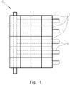
- Fig. 1 schematically shows a top view of an embodiment of a transport device 10 build from several, in the embodiment shown twenty transport device units 1.
- the transport device units 1 are fixed to a support frame comprising support bars 12.
- Each of the transport device units 1 shown has a square basic shape allowing building of transport devices 10 of various designs by adding additional transport device units 1 at either side of already existing units 1 and/or removing transport device units 1 from the device 10 shown in Fig. 1 .
- the transport device units have a different basic shape, for example a triangular basic shape or a hexagonal basic shape.
- all transport device units 1 have the same basic shape, wherein the shape is a tessellating shape.
- a transport device is composed of transport device units 1 having different basic shapes.
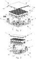
- Fig. 2 shows a transport device unit 1 for building a transport device 10 of Fig. 1 in an exploded view.
- Fig. 3 shows the unit 1 of Fig. 2 in an exploded sectional view.
- the transport device unit 1 comprises three modules, namely a base plate module 2 for fixing the transport device unit 1 to the support frame, an actuator module 3 with a plurality of electro-magnetic actuators 30 mounted to a carrier element 31, and a driving surface module 4. Adjacent transport device units 1 are connected by means of corner supports 5.
- the base plate module 2 shown comprises a base plate 20 having an essentially square basic shape with four sides and four corners.
- a recess 21 surrounded by walls 22 is provided for accommodating a fan 32 mounted at the actuator module 3 and protruding from a bottom side of the carrier element 31.
- filter elements 230 are mounted at the inside of the walls.
- a wiring board 6 is mounted to the base plate 20 at one corner region thereof.
- the wiring board 6 has an L-shaped basic shape and is arranged directly adjacent to the recess 21.
- Neighboring base plate modules 2 are coupled to each other.
- an angled connection bracket 24 extending in a vertical direction and perpendicular to a surface area of the base plate 20 is provided.
- Adjacent base plates 20, and thus adjacent base plate modules 2 are connected by means of the corner supports 5 attached to two, three or four connection brackets 24 of the base plates 20 of neighboring transport device units 1.
- the driving surface module 4 is coupled to a top end of the corner supports 5 by means of connecting structures 40 provided at each of the four corners of the driving surface module 4.
- the actuator module 3 is supported by the base plate module 2.
- the base plate module 2 and the actuator module 3 are provided with cooperating male and female coupling elements.
- the base plate 20 is provided with four receiving openings 25, 26 adapted to receive four stands 33, 34 provided at the actuator module 3.
- a plurality of base plate modules 2 is mounted to the support bars 12 (see Fig. 2 ), wherein adjacent base plate modules 2 are aligned and connected to each other by means of the corner supports 5.
- a wiring of the transport device units 1 can be completed.
- the actuator modules 3 are mounted to the base plate modules 2, wherein the stands 33, 34 of the actuator module 3 are inserted into the receiving openings 25, 26 of the base plate 20.
- the driving surface module 4 is mounted to the base plate module 2 via the corner supports 5, wherein the connecting structures 40 of the driving surface module 4 are coupled to the corner supports 5.
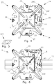
- Fig. 4 shows the base plate 20 of the base plate module 2 in a top view.
- Fig. 6 shows the base plate module 2 in a top view mounted to a support bar 12.
- the surface area of the base plate 20 is provided with four rhombic apertures 27 each adapted to receive a fastening bolt 121 (see Fig. 6 ) equipped with a washer 122 and a rhombic slot nut 123, which rhombic slot nut 123 is schematically shown in Fig. 5 .
- the slot nut 123 can be mounted to the fastening bolt 121 and inserted from above into a groove of the support bar 12 passing through the rhombic apertures 27. This allows for an easy mounting, wherein the fastening bolt 121 can be tightened after all base plate modules 2 of a transport device are aligned to each other.
- the surface area of the base plate 20 is provided with receiving slits 23 on the internal side of the walls 22 surrounding the recess 21.
- the receiving slits 23 allow for a mounting of filter elements 230 (see Fig. 6 and 7 ) from below, in case the support bar 12 does not hinder an access to the receiving slit 23.
- the filter element 230 can be mounted from above.
- a wiring board 6 is mounted to the base plate 20 by means of screws 61 (see Fig. 6 ).
- the base plate 20 is provided with threaded holes 28 for receiving the screws 61.
- an earth or ground cable 60 of the wiring board 6 is connected to the fastening bolt 121, and the fastening bolt 121 is used for a grounding of the wiring board 6.
- the base plate module 2 serves as a mounting platform for mounting the actuator module 3 and the driving surface module 4.
- the actuator module 3 is mounted to the base plate module 2 by means of stands 33, 34 (see Fig. 3 ) serving as male coupling elements to be inserted into receiving openings 25, 26 provided at the base plate 20.
- the receiving openings 25, 26 adapted to receive the stands 33, 34 differ in design for providing a mechanical coding or keying system not having rotational symmetry. Thereby it is ensured that the actuator module 3 can only be mounted in one particular orientation to the base plate module 2.
- two receiving openings 25 have a U-shaped design, whereas the other two receiving openings 26 have a T-shaped design.
- Each receiving opening 25, 26 is arranged at a center of one of the sides of the base plate 20 between two corners.
- a keying structure is provided by arranging at least one of the receiving openings 25, 26 and the corresponding stand 33, 34 offset from a center closer to one corner.
- each connection bracket 24 is provided with two longitudinal grooves 240 at its two legs, which longitudinal grooves 240 extend parallel to the two adjoining sides and perpendicular to a surface area of the base plate 20.
- a coupling element can be inserted into the grooves from above.
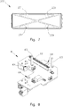
- Fig. 7 shows a filter element 230 of the base plate module 2 of Fig. 6 in a side view.
- the filter element 230 has mirror symmetry allowing a mounting of the filter element 230 in four different orientations.
- the filter element 230 is provided with snap-fit connectors 231 for detachably securing the filter element 230 in position at the base plate 20 of the base plate module 2. If required, the filter element 230 can be removed and cleaned or replaced. In case access to the filter element 230 is possible from below, such a removal and/or replacement is possible without disassembling the transport device unit 1.
- Fig. 8 shows the wiring board 6 of the base plate module 2 of Fig. 6 in a perspective view.
- the wiring board 6 is provided with a board-to-board connector 62 for electrically connecting the wiring board 6 and the actuator module 3 (see Fig. 2 ), more particular for electrically connecting the wiring board 6 and an actuator module wiring board 35 (see Fig. 11 ).
- two centering pins 63 are provided, which are received in corresponding centering holes (36, see Fig. 10 ) at the actuator module 3.
- the wiring board 6 is float-mounted to the base plate 20 of the base plate module 2.
- the wiring board 6 is provided with through holes 64 for the fixation screws 61 (see Fig. 6 ), which through holes 64 are larger in diameter than the fixation screws 61. Hence, the wiring board 6 is mounted moveably within limits by means of the fixation screws 61 to the base plate 20.
- Figs. 9 and 10 show the actuator module 3 with the carrier element 31 and the actuators 30 in a perspective view from above and from below, respectively.
- Fig. 11 shows the actuator module 3 in a different orientation than Fig. 9 and wherein the actuators 30 are removed.
- Fig. 12 shows an electro-magnetic actuator 30 of the actuator module 3.
- the actuator module 3 has an essentially square basic shape with four equal sides and four corners. It is adapted to be mounted to the base plate module 2 by means of the stands 33, 34 inserted into receiving openings 25, 26 (see Fig. 4, 6 ).
- the carrier element 31 is provided with four stands 33, 34 adapted to be inserted into four receiving openings 25, 26 of the base plate module 2 (see Fig. 2 ).
- the receiving openings 25, 26 as well as the corresponding stands 33, 34 differ in design for providing a mechanical coding not having rotational symmetry.
- two stands 33 have a U-shaped cross-section, whereas the other two stands 34 have a T-shaped cross-section.
- Each stand 33, 34 is arranged at a center of one of the sides of the carrier element 31.
- the actuator module 3 comprises an actuator module wiring board 35 provided with contact pins 350 accessible via a bottom surface 310 of the carrier element 31.
- the contact pins 350 are adapted to connect with the board-to-board connector 62 (see Fig. 8 ) of the wiring board 6.
- two centering holes 36 are provided at the bottom surface 310 as well as at the actuator module wiring board 35.
- the centering holes 36 are adapted for receiving the centering pins 63 of the wiring board 6 for aligning the contact pins 350 of the actuator module wiring board 35 with the board-to-board connector 62.
- the actuators 30 are electrically and mechanically connected to the actuator module wiring board 35.
- the actuator module wiring board 35 is equipped with a plurality of sockets 351 adapted to receive contact pins 301 provided at the actuators 30 (see Fig. 12 ).
- the actuator module 3 comprises a grid structure 37 made of a magnetically conductive material, in particular a metal, comprising a plurality of bearing pins 370.
- the bearing pins 370 are adapted to receive one actuator 30 each, wherein the actuators 30 are provided with corresponding cores 302.
- the fan 32 is provided.
- the length of the stands 33, 34 exceeds the distance over which the fan 32 protrudes from the bottom surface 310 such that when placing the actuator module 3 on a planar surface, for example during transport, for storage and/or for an assembly, the distal ends of the stands 33, 34 contact this planar surface and the fan 32 is distanced from the planar surface.
- a guiding groove 38 for a removal tool 8 is provided, as will be explained in more detail with reference to Figs. 21 and 22 below.
- Fig. 13 and 14 show the driving surface module 4 in a perspective view from above and from below, respectively.
- Fig. 15 is a perspective view from below showing a detail of two adjacent driving surface modules 4 of Fig. 14 .
- the driving surface module 4 is provided with a driving surface element 41.
- the driving surface element 41 in particular is made of a material suitable for slidingly transporting sample carriers (not shown) along the top surface of the driving surface element 41.
- the driving surface element 41 has an essentially square basic shape with four sides of equal length and four corners.
- the driving surface module 4 is detachably supported by support elements.
- the driving surface module 4 is detachably supported by the corner supports 5 (see Fig. 2 ) serving as support element for the driving surface module 4.
- connecting structures 40 are provided for connecting the driving surface module 4 via the corner supports 5 with the base plate module 2 (see Fig. 2 ).
- the driving surface module 4 comprises a sensor board arranged at a bottom side of the driving surface element 41. Hence, the sensor board is positioned close to the driving surface across which sample support carriers (not shown) are transported.
- the sensor board at least forms part of a device for sensing a presence or position of an individual sample container carrier moved across the upper side of the driving surface element 41.
- the driving surface element 41 is transparent to IR light, wherein the sensor board can be equipped with multiple IR based reflection light barriers arranged in a grid, and the sample container carriers can be adapted to reflect IR radiation emitted by the light barriers.
- the driving surface module 4 When mounting the driving surface module 4 to the base plate module 2 by means of the corner supports 5, the driving surface module 4 is positioned with high accuracy in relation to the base plate module 2.
- a rim 42 is provided.
- the driving surface elements 41 of adjacent transport device units 1 overlap each other at their side regions.
- a transition between the top surface of the driving surface element 41 and the rim 42 is provided with a stepped portion 43.
- a transition between the top surface of the driving surface element 41 and the rim 42 is provided with a complementary overhang portion 44.
- the stepped portion 43 and the overhang portion 44 are adapted to each other such that the overhang portion 44 rests on the stepped portion 43 and is supported by the stepped portion 43 for a smooth transition between two driving surface modules 4.
- adjacent transport device units 1 are arranged such that in each case a side provided with an overhang portion 44 contacts a side provided with a stepped portion 43.
- resilient elements 450, 451 are provided underneath the driving surface element 41 for forcing the stepped portion 43 towards the overhang portion 44.
- the resilient elements 450, 451 in the embodiment shown comprise pairs of hooked-shaped elements 450 arranged underneath each overhang portion 44, wherein each pair of hooked-shaped elements 450 is interacting with a tongue-shaped element 451 provided at sides of the driving surface element 41 having a stepped portion 43.
- the tongue-shaped element 451 and the stepped portion 43 are arranged between the overhang portion 44 and the hooked-shaped elements 450.
- a grid-shaped resilient component 45 is provided, wherein the resilient elements 450, 451 are formed at ends of grid-lines of the grid-shaped resilient component 45.
- Grid-lines of the grid-shaped resilient component 45 are arranged above some of the actuators 30 of the actuator module 3 (see Fig. 2 ), wherein the grid-lines are provided with recesses 452 for receiving upper ends of the actuators 30.
- the grid-shaped resilient component 45 is mounted to the bottom surface of the driving surface element 41.
- the bottom surface of the driving surface element 41 is provided with screw sockets 410 for fixing the grid-shaped resilient component 45 to the driving surface element 41.
- a sealing cord 46 is provided.
- the sealing cord 46 extends along two sides of the driving surface element 41, namely the sides provided with the overhang portion 44.
- the sealing cord 46 is mounted at the respective sides to the rim 42.
- a groove for mounting of the sealing cord 46 can be provided.
- the rim 42 is provided with a sealing projection for contacting the sealing cord 46.
- the driving surface element 40 has no rotational symmetry and can be mounted only in one orientation.
- Fig. 16 shows a detail XVI of Fig. 14 , wherein the connecting structure 40 for connecting the driving surface module 4 with the corner support 5 (see Fig. 2 ) is shown in more detail.
- the connecting structure 40 comprises a connection pin 400 formed integrally with the driving surface element 41.
- two snap-fit elements 402 are provided, which in the embodiment shown are formed integrally with the grid-shaped component 45.
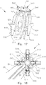
- Fig. 17 is a perspective view of a corner support 5 for connecting adjacent transport device units 1 (see Fig. 1 ).
- the corner support 5 in the embodiment shown functions as a cross-shaped connection node for both, a plurality of base plate modules 2 and a plurality of driving surface modules 4.
- the corner supports 5 are arranged at the four corners of the transport device unit 1, wherein the driving surface module 4 rests on the four corner supports 5.
- Each corner support 5 is provided with a liquid trap recess 50 at its center for collecting liquid accidently spilled on the driving surface.
- each pair is connected and aligning up to four base plate modules 2
- four pairs of snap-fit elements 511, 512, 513, 514 and four pairs of ribs 521, 522, 523, 524 (only partly visible in Fig. 17 ) are provided.
- the snap-fit elements 511, 512, 513, 514 as well as the ribs 521, 522, 523, 524 of each pair are arranged at an angle of 90° to each other.
- the ribs 521, 522, 523, 524 are adapted to enter into the longitudinal grooves 240 of the connecting bracket 24 of the base plate modules 2 (see Fig.
- Fig. 18 shows a bottom view of a corner support 5 attached to a base plate 20, wherein ribs 521 (not visible in Fig. 18 ) are inserted into longitudinal grooves 240 of the connecting bracket 24 of the base plate 20 and snap-fit elements 511 are snapped to the hook provided at the side of the connecting bracket 24 directly adjacent to this longitudinal groove 240.
- the corner support 5 shown in Fig. 17 is further provided with four pairs of latch elements 531, 532, 533, 534 (only partly visible in Fig. 17 ) for connecting and aligning up to four driving surface modules 4.
- the latch elements 531, 532, 533, 534 of each pair are also arranged at an angle of 90° to each other. Between the two latch elements 531, 532, 533, 534 of each pair, an opening 541, 542, 543, 544 is provided.
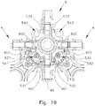
- Fig. 19 shows a bottom view of a corner support 5, wherein two connecting structures 40 of two adjacent driving surface modules 4 are coupled by means of the corner support 5.
- the connection pin 400 of each connecting structure 40 is inserted into an opening 541, 542 and the snap-fit elements 402 of the respective connecting structure 40 interlocks with the latch elements 531. 532 arranged on either side of the respective opening 541, 542.
- a sealing cord 46 is arranged between two adjacent driving surface modules 4.
- Fig. 20 schematically shows a sectional view of two adjacent transfer units with base plate elements 20 and driving surface modules 4, which are coupled by means of a corner support 5.
- connection pins 400 of each driving surface module 4 are inserted into an associated opening 541, 544 of a common corner support 5.
- the sealing cord 46 forces the two driving surface modules 4 apart, and hence, the connection pins 400 are forced against the edges of the openings 541, 544 receiving the connection pins 400 as schematically shown by two arrows in Fig. 20 .
- This allows for a precise positioning of the adjacent driving surface modules 4 with respect to each other. Further, it is avoided that acceptable tolerances between adjacent driving surface modules 4 accumulate along the driving surface.
- the corner support 5 also serves to clamp a base plate element 20 to an adjacent base plate element 20.
- two parallel ribs 521, 524 are inserted into two parallel arranged longitudinal grooves 240 of the brackets 24 of the adjacent base plate elements 20.
- the transport device can be easily adapted to changing conditions and/or requirements of a laboratory automation system. Further, malfunctioning transport device units 1, in particular malfunction actuator modules 3, can be easily and quickly replaced.
- the transport device units 1 are arranged tightly at the transport device. For removal of a driving surface module 4, said driving surface module 4 can be raised at one side having an overhang portion 44 and inclined.
Landscapes
- Physics & Mathematics (AREA)
- Health & Medical Sciences (AREA)
- Life Sciences & Earth Sciences (AREA)
- Chemical & Material Sciences (AREA)
- Analytical Chemistry (AREA)
- Biochemistry (AREA)
- General Health & Medical Sciences (AREA)
- General Physics & Mathematics (AREA)
- Immunology (AREA)
- Pathology (AREA)
- Non-Mechanical Conveyors (AREA)
- Automatic Analysis And Handling Materials Therefor (AREA)
Claims (11)
- Transportvorrichtungseinheit für eine Transportvorrichtung (10), die unter Verwendung einer Mehrzahl von Transportvorrichtungseinheiten (1) zusammengesetzt ist, wobei die Transportvorrichtungseinheit (1) umfasst:ein Aktuatormodul (3) mit einer Mehrzahl von elektromagnetischen Aktuatoren (30) und mit einer Aktuatormodul-Leiterplatte (35),wobei die Transportvorrichtungseinheit (1) weiter umfasst:- ein Basisplattenmodul (2) mit einer Basisplatte (20) zum Befestigen der Transportvorrichtungseinheit (1) an einem Trägerrahmen, wobei das Aktuatormodul (3) vom Basisplattenmodul (2) gestützt ist, und- ein Verfahrflächenmodul (4) mit einem Verfahrflächenelement (41), wobei das Verfahrflächenelement (41) über dem Aktuatormodul (3) angeordnet ist, die Aktuatoren (30) bedeckt und dazu ausgebildet ist, Probenbehälterträger zu tragen,wobei eine Leiterplatte (6) an der Basisplatte (20) angebracht ist, wobei die Leiterplatte (6) einen Board-to-Board-Verbinder (62) zum elektrischen und mechanischen Koppeln mit der Aktuatormodul-Leiterplatte (35) des Aktuatormoduls (3) aufweist.
- Transportvorrichtungseinheit nach Anspruch 1, dadurch gekennzeichnet, dass die Transportvorrichtungseinheit (1) eine tessellierende Grundform aufweist, insbesondere eine regelmäßig polygonale Grundform aufweist.
- Transportvorrichtungseinheit nach Anspruch 1 oder 2, dadurch gekennzeichnet, dass das Verfahrflächenmodul (4) entfernbar am Basisplattenmodul (2) angebracht ist.
- Transportvorrichtungseinheit nach einem der Ansprüche 1, 2 oder 3, dadurch gekennzeichnet, dass die Basisplatte (20) mindestens eine Öffnung (27) aufweist, die so ausgebildet ist, dass es möglich ist, einen Nutenstein (123) hindurchzuführen, um die Transportvorrichtungseinheit (1) an einer Auflageleiste (12) des Trägerrahmens mittels des Nutensteins (123) anzubringen, wobei insbesondere mindestens zwei Öffnungen (27) angeordnet in einem Winkel von 90° vorgesehen sind.
- Transportvorrichtungseinheit nach einem der Ansprüche 1 bis 4, dadurch gekennzeichnet, dass die Leiterplatte (6) und die Aktuatormodul-Leiterplatte (35) mit kooperierenden Zentrierelementen (63, 36) versehen sind, wobei die Leiterplatte (6) an der Basisplatte (20) schwimmend gelagert ist.
- Transportvorrichtungseinheit nach einem der Ansprüche 1 bis 5, dadurch gekennzeichnet, dass die Basisplatte (20) mit einer Ausnehmung (21) zum Aufnehmen eines Lüfters (32) versehen ist, wobei mindestens ein Filterelement (230) entfernbar an Innenseiten von die Ausnehmung (21) umgebenden Wandungen (22) angebracht ist.
- Transportvorrichtungseinheit nach Anspruch 6, dadurch gekennzeichnet, dass eine Ausnehmung (21) mit einer rechteckigen Grundform zum Aufnehmen eines Lüfters (32) vorgesehen ist, wobei vier separate Filterelemente (230) entfernbar an Innenseiten von die Ausnehmung (21) umgebenden Wandungen (22) angebracht sind, wobei insbesondere die Basisplatte (20) mit Aufnahmeschlitzen (23) zum Anbringen der Filterelemente (230) von unten versehen ist.
- Transportvorrichtungseinheit nach einem der Ansprüche 1 bis 7, dadurch gekennzeichnet, dass das Aktuatormodul (3) mit einer Aktuatormodul-Leiterplatte (35) mit Buchsen (351) und einer magnetisch leitfähigen Struktur versehen ist und die Aktuatoren (30) mit Kontaktstiften (301) versehen sind, wobei die Aktuatoren (30) derart an der magnetisch leitfähigen Struktur angebracht sind, dass die Kontaktstifte (301) mit den Buchsen elektrisch und mechanisch verbunden sind, wobei insbesondere die magnetisch leitfähige Struktur mit Lagerstiften (370) versehen ist, die so ausgebildet sind, dass sie Aktuatoren (30) mit einem Kern (302) aufnehmen.
- Transportvorrichtung, umfassend eine Mehrzahl von Transportvorrichtungseinheiten (1) nach einem der Ansprüche 1 bis 8, wobei insbesondere Basisplattenmodule (2) benachbarter Transportvorrichtungseinheiten (1) an ihren angrenzenden Ecken mittels Eckenstützen (5) gekoppelt und ausgerichtet sind.
- Laborprobenverteilungssystem mit einer Transportvorrichtung (10) nach Anspruch 9 und einer Mehrzahl von Probenbehälterträgern, wobei die Probenbehälterträger jeweils mindestens ein magnetisch wirksames Element, bevorzugt mindestens einen Permanentmagneten, umfassen und so ausgebildet sind, dass sie einen Probenbehälter tragen, der eine Probe enthält.
- Laborautomatisierungssystem mit einer Mehrzahl von prä-analytischen, analytischen und/oder post-analytischen Stationen und mit einem Verteilungssystem nach Anspruch 10.
Applications Claiming Priority (3)
| Application Number | Priority Date | Filing Date | Title |
|---|---|---|---|
| EP16157587.3A EP3211428A1 (de) | 2016-02-26 | 2016-02-26 | Transportvorrichtungseinheit für ein laborprobenverteilungssystem |
| EP17701158.2A EP3420365B1 (de) | 2016-02-26 | 2017-01-25 | Transportvorrichtungseinheit für ein laborprobenverteilungssystem |
| PCT/EP2017/051534 WO2017144219A1 (en) | 2016-02-26 | 2017-01-25 | Transport device unit for a laboratory sample distribution system |
Related Parent Applications (2)
| Application Number | Title | Priority Date | Filing Date |
|---|---|---|---|
| EP17701158.2A Division EP3420365B1 (de) | 2016-02-26 | 2017-01-25 | Transportvorrichtungseinheit für ein laborprobenverteilungssystem |
| EP17701158.2A Division-Into EP3420365B1 (de) | 2016-02-26 | 2017-01-25 | Transportvorrichtungseinheit für ein laborprobenverteilungssystem |
Publications (2)
| Publication Number | Publication Date |
|---|---|
| EP3575801A1 EP3575801A1 (de) | 2019-12-04 |
| EP3575801B1 true EP3575801B1 (de) | 2020-12-16 |
Family
ID=55442718
Family Applications (3)
| Application Number | Title | Priority Date | Filing Date |
|---|---|---|---|
| EP16157587.3A Ceased EP3211428A1 (de) | 2016-02-26 | 2016-02-26 | Transportvorrichtungseinheit für ein laborprobenverteilungssystem |
| EP19187853.7A Active EP3575801B1 (de) | 2016-02-26 | 2017-01-25 | Transportvorrichtungseinheit für ein laborprobenverteilungssystem |
| EP17701158.2A Active EP3420365B1 (de) | 2016-02-26 | 2017-01-25 | Transportvorrichtungseinheit für ein laborprobenverteilungssystem |
Family Applications Before (1)
| Application Number | Title | Priority Date | Filing Date |
|---|---|---|---|
| EP16157587.3A Ceased EP3211428A1 (de) | 2016-02-26 | 2016-02-26 | Transportvorrichtungseinheit für ein laborprobenverteilungssystem |
Family Applications After (1)
| Application Number | Title | Priority Date | Filing Date |
|---|---|---|---|
| EP17701158.2A Active EP3420365B1 (de) | 2016-02-26 | 2017-01-25 | Transportvorrichtungseinheit für ein laborprobenverteilungssystem |
Country Status (5)
| Country | Link |
|---|---|
| US (2) | US10578632B2 (de) |
| EP (3) | EP3211428A1 (de) |
| JP (2) | JP6605757B2 (de) |
| CN (2) | CN108780106B (de) |
| WO (1) | WO2017144219A1 (de) |
Families Citing this family (30)
| Publication number | Priority date | Publication date | Assignee | Title |
|---|---|---|---|---|
| EP2589967A1 (de) | 2011-11-04 | 2013-05-08 | Roche Diagnostics GmbH | Laborprobenverteilungssystem und entsprechendes Betriebsverfahren |
| AU2013202805B2 (en) * | 2013-03-14 | 2015-07-16 | Gen-Probe Incorporated | System and method for extending the capabilities of a diagnostic analyzer |
| EP2995958A1 (de) | 2014-09-15 | 2016-03-16 | Roche Diagniostics GmbH | Verfahren zum Betrieb einer Laborprobe Verteilungssystem, Laborprobenverteilungssystems und Laborautomatisierungssystem |
| EP3096146A1 (de) | 2015-05-22 | 2016-11-23 | Roche Diagniostics GmbH | Verfahren zum betrieb eines laborprobenverteilungssystems, laborprobenverteilungssystem und laborautomatisierungssystem |
| EP3095739A1 (de) | 2015-05-22 | 2016-11-23 | Roche Diagniostics GmbH | Verfahren zum betrieb eines laborprobenverteilungssystems, laborprobenverteilungssystem und laborautomatisierungssystem |
| EP3112874A1 (de) | 2015-07-02 | 2017-01-04 | Roche Diagnostics GmbH | Speichermodul, verfahren zum betrieb eines laborautomatisierungssystems und laborautomatisierungssystem |
| EP3121603A1 (de) | 2015-07-22 | 2017-01-25 | Roche Diagnostics GmbH | Probenbehälterträger, laborprobenverteilungssystem und laborautomatisierungssystem |
| EP3211430A1 (de) * | 2016-02-26 | 2017-08-30 | Roche Diagnostics GmbH | Transportvorrichtung mit grundplattenmodulen |
| EP3211429A1 (de) | 2016-02-26 | 2017-08-30 | Roche Diagnostics GmbH | Transportvorrichtung mit gefliester fahroberfläche |
| CN109196363A (zh) | 2016-06-03 | 2019-01-11 | 豪夫迈·罗氏有限公司 | 实验室样品分配系统和实验室自动化系统 |
| EP3255519B1 (de) | 2016-06-09 | 2019-02-20 | Roche Diagniostics GmbH | Laborprobenverteilungssystem und verfahren zum betrieb eines laborprobenverteilungssystems |
| JP6752350B2 (ja) | 2016-08-04 | 2020-09-09 | エフ.ホフマン−ラ ロシュ アーゲーF. Hoffmann−La Roche Aktiengesellschaft | ラボラトリ試料分配システム及びラボラトリ自動化システム |
| EP3355065B1 (de) | 2017-01-31 | 2021-08-18 | Roche Diagnostics GmbH | Laborprobenverteilungssystem und laborautomatisierungssystem |
| EP3357842B1 (de) | 2017-02-03 | 2022-03-23 | Roche Diagnostics GmbH | Laborautomatisierungssystem |
| EP3410123B1 (de) | 2017-06-02 | 2023-09-20 | Roche Diagnostics GmbH | Verfahren zum betrieb eines laborprobenverteilungssystems, laborprobenverteilungssystem und laborautomatisierungssystem |
| EP3428653B1 (de) | 2017-07-13 | 2021-09-15 | Roche Diagnostics GmbH | Verfahren zum betreiben eines laborprobenverteilungssystems, laborprobenverteilungssystem und laborautomatisierungssystem |
| EP3456415B1 (de) | 2017-09-13 | 2021-10-20 | Roche Diagnostics GmbH | Probenbehälterträger, laborprobenverteilungssystem und laborautomatisierungssystem |
| EP3537159B1 (de) | 2018-03-07 | 2022-08-31 | Roche Diagnostics GmbH | Verfahren zum betrieb eines laborprobenverteilungssystems, laborprobenverteilungssystem und laborautomatisierungssystem |
| EP3540443B1 (de) | 2018-03-16 | 2023-08-30 | Roche Diagnostics GmbH | Laborsystem, laborprobenverteilungssystem und laborautomationssystem |
| SG11202108157WA (en) * | 2019-01-30 | 2021-08-30 | Life Tech Holdings Pte Limited | Biological analysis system and methods |
| EP3925911B1 (de) | 2020-06-19 | 2023-05-24 | Roche Diagnostics GmbH | Laborprobenverteilungssystem und entsprechendes verfahren zum betrieb |
| EP3940388B1 (de) | 2020-07-15 | 2024-04-10 | Roche Diagnostics GmbH | Laborprobenverteilungssystem und verfahren zum betrieb davon |
| EP3974839B1 (de) | 2020-09-23 | 2024-03-27 | Roche Diagnostics GmbH | Verfahren zur erkennung und meldung eines betriebsfehlers in einem in-vitro-diagnosesystem, transportvorrichtung für ein laborprobenverteilungssystem und laborprobenverteilungssystem |
| EP4001923B1 (de) | 2020-11-23 | 2024-06-05 | Roche Diagnostics GmbH | Laborprobenverteilungssystem und laborautomatisierungssystem |
| EP4016084B1 (de) * | 2020-12-21 | 2025-12-03 | Roche Diagnostics GmbH | Modulare transportebene und laborverteilungssystem |
| US11747356B2 (en) | 2020-12-21 | 2023-09-05 | Roche Diagnostics Operations, Inc. | Support element for a modular transport plane, modular transport plane, and laboratory distribution system |
| CN119422048A (zh) | 2022-06-28 | 2025-02-11 | 豪夫迈·罗氏有限公司 | 安全点模式 |
| DE102022207929A1 (de) | 2022-08-01 | 2024-02-01 | Optima consumer GmbH | Transportschlitten zum Transport von Behältnissen in einer Abfüll- und/oder Verpackungsanlage |
| EP4458744A1 (de) * | 2023-05-02 | 2024-11-06 | Roche Diagnostics GmbH | Transportvorrichtung und laborprobenverteilungssystem |
| EP4530637A1 (de) * | 2023-09-29 | 2025-04-02 | Roche Diagnostics GmbH | Transportvorrichtung und laborprobenverteilungssystem |
Family Cites Families (273)
| Publication number | Priority date | Publication date | Assignee | Title |
|---|---|---|---|---|
| US3273727A (en) | 1966-09-20 | Load handling apparatus | ||
| US3240460A (en) | 1963-01-03 | 1966-03-15 | Schlumberger Ltd | Furniture sheath |
| US3281888A (en) | 1965-01-13 | 1966-11-01 | Edward M Stankewich | Stud shaft rollers |
| US3653485A (en) | 1971-03-05 | 1972-04-04 | Transportation Technology | An air bearing conveyor |
| US3901656A (en) | 1972-08-24 | 1975-08-26 | American Monitor Corp | Apparatus and method for preparing and presenting serum chemistries for analyzation |
| DE2722865C2 (de) | 1977-05-20 | 1986-06-19 | Krupp Polysius Ag, 4720 Beckum | Rohrpostförderanlage für Feingutproben |
| US4150666A (en) | 1977-06-27 | 1979-04-24 | Sherwood Medical Industries Inc. | Tube holder for blood collection tubes of different sizes |
| SU685591A1 (ru) | 1977-08-01 | 1979-09-15 | Украинский Государственный Институт По Проектированию Металлургических Заводов | Патрон пневмопочты |
| JPS56147209A (en) | 1980-04-16 | 1981-11-16 | Hitachi Kiden Kogyo Ltd | Automatic steering method for unattended carrying vehicle |
| US4544068A (en) | 1983-08-16 | 1985-10-01 | The United States Of America As Represented By The Administrator Of The National Aeronautics And Space Administration | Laboratory glassware rack for seismic safety |
| JPS60223481A (ja) | 1984-04-18 | 1985-11-07 | Nippon Telegr & Teleph Corp <Ntt> | 磁気浮上案内装置 |
| JPH0761814B2 (ja) | 1984-09-10 | 1995-07-05 | 三菱化学株式会社 | 搬送装置 |
| JPS6181323A (ja) | 1984-09-27 | 1986-04-24 | Mitsubishi Chem Ind Ltd | 整列物体の移動装置 |
| JPS6194925A (ja) | 1984-10-12 | 1986-05-13 | Mitsubishi Chem Ind Ltd | 搬送用装置 |
| GB2165515A (en) | 1984-10-12 | 1986-04-16 | Mitsubishi Chem Ind | Conveyor |
| JPS61217434A (ja) | 1985-03-20 | 1986-09-27 | Mitsubishi Chem Ind Ltd | 搬送用装置 |
| JPS61174031A (ja) | 1985-01-29 | 1986-08-05 | Youichi Oohira | リニア誘導モ−タ形x−yアクチユエ−タを用いた分岐を目的とする搬送装置 |
| JPS62100161A (ja) | 1985-10-23 | 1987-05-09 | Shin Etsu Chem Co Ltd | 平面モ−タ |
| US4771237A (en) | 1986-02-19 | 1988-09-13 | Panametrics | Method and apparatus for calibrating a displacement probe using a polynomial equation to generate a displacement look-up table |
| JPH0338704Y2 (de) | 1986-04-30 | 1991-08-15 | ||
| JPS6331918A (ja) | 1986-07-16 | 1988-02-10 | フエコ・エンジニア−ド・システムズ・インコ−ポレ−テツド | 回転および引込可能な容器保持装置およびそのコンベア |
| JPS6348169A (ja) | 1986-08-14 | 1988-02-29 | Fuji Elelctrochem Co Ltd | 圧電アクチユエ−タ |
| JPH0239554Y2 (de) | 1986-11-15 | 1990-10-23 | ||
| US4855110A (en) * | 1987-05-06 | 1989-08-08 | Abbott Laboratories | Sample ring for clinical analyzer network |
| JPS63290101A (ja) | 1987-05-22 | 1988-11-28 | Toshiba Corp | リニアモ−タ式搬送装置 |
| JPH01148966A (ja) | 1987-12-04 | 1989-06-12 | Hitachi Kiden Kogyo Ltd | 検体搬送装置 |
| JPH01266860A (ja) | 1988-04-19 | 1989-10-24 | Yukitaka Furukawa | 試験管を冷却することが出来る試験管保持器具 |
| JP2585747B2 (ja) | 1988-09-21 | 1997-02-26 | 株式会社ダイフク | リニアモータ利用の搬送設備 |
| JPH02163637A (ja) | 1988-12-16 | 1990-06-22 | Fuji Photo Film Co Ltd | 液体化学分析装置 |
| DE3909786A1 (de) | 1989-03-24 | 1990-09-27 | Schlafhorst & Co W | Vorrichtung zum transportieren von kopsen und huelsen zwischen im verlauf des transportes wechselnden ebenen |
| DE4011797C2 (de) | 1989-06-10 | 1998-02-12 | Schlafhorst & Co W | Transportsystem für eine automatische Textilmaschine zum gesteuerten Führen von Paletten entlang vorgegebener Transportwege |
| JPH03112393A (ja) | 1989-09-21 | 1991-05-13 | Kao Corp | 搬送装置 |
| US5457368A (en) | 1993-03-09 | 1995-10-10 | University Of Utah Research Foundation | Mechanical/electrical displacement transducer |
| JPH03192013A (ja) | 1989-12-21 | 1991-08-21 | Toshiba Corp | 表示装置 |
| US5115905A (en) * | 1990-06-14 | 1992-05-26 | Compaq Computer Corporation | Magnetically secured conveyor system for printed circuit assemblies |
| JP2973133B2 (ja) | 1990-09-19 | 1999-11-08 | 株式会社日立製作所 | 臨床検査用検体振り分け装置 |
| US5180048A (en) * | 1990-10-12 | 1993-01-19 | Mitsubishi Jukogyo Kabushiki Kaisha | Magnetic levitating transportation system |
| EP0529157A1 (de) | 1991-08-22 | 1993-03-03 | Mitsubishi Jukogyo Kabushiki Kaisha | Wechselstrom-Transportsystem mit magnetischer Schwebewirkung |
| JPH0569350A (ja) | 1991-09-11 | 1993-03-23 | Toshiba Corp | 軌道走行式ロボツト設備の保全装置 |
| JP3047571B2 (ja) | 1991-11-20 | 2000-05-29 | 株式会社日立製作所 | 臨床検査用装置 |
| JPH05180847A (ja) | 1991-12-31 | 1993-07-23 | Hiranuma Sangyo Kk | 自動分析装置用サイクラ |
| DE69308493T2 (de) | 1992-06-29 | 1997-10-23 | Dade Int Inc | Träger für proberöhrchen |
| EP0648698B1 (de) | 1992-07-07 | 1998-01-07 | Ebara Corporation | Durch magnetische wirkung schwebende transportvorrichtung |
| JPH0626808A (ja) | 1992-07-09 | 1994-02-04 | Ebara Corp | センサターゲット |
| EP0590222A1 (de) | 1992-09-30 | 1994-04-06 | STMicroelectronics S.r.l. | Magnetischer Lagegeber |
| EP0601213A1 (de) | 1992-10-29 | 1994-06-15 | Hamilton Bonaduz AG | Vorrichtung zum Transportieren von Waren |
| JPH06148198A (ja) | 1992-11-05 | 1994-05-27 | Hitachi Ltd | 分析機器の汚染防止装置 |
| JPH06156730A (ja) | 1992-11-13 | 1994-06-03 | Ebara Corp | 搬送装置 |
| JP3387951B2 (ja) | 1993-01-19 | 2003-03-17 | 株式会社荏原製作所 | 基板保管装置 |
| JPH07228345A (ja) | 1994-02-14 | 1995-08-29 | Ebara Corp | トンネル搬送装置 |
| JP2574126B2 (ja) | 1994-02-28 | 1997-01-22 | 照明 伊藤 | 検体遠心分離処理方法およびその装置 |
| JPH07301637A (ja) | 1994-04-29 | 1995-11-14 | Syst Sutatsuku:Kk | 検体搬送装置 |
| US5636548A (en) | 1994-05-16 | 1997-06-10 | Tesoro Alaska Petroleum Company | Analog hall-effect liquid level detector and method |
| US5523131A (en) | 1994-11-01 | 1996-06-04 | Innovative Premiums Inc. | Self-propelled table novelty device |
| IL118232A (en) | 1995-05-15 | 2001-07-24 | Smithkline Beecham Corp | Bottle holder |
| US5925956A (en) | 1995-06-30 | 1999-07-20 | Nikon Corporation | Stage construction incorporating magnetically levitated movable stage |
| JPH0917848A (ja) | 1995-06-30 | 1997-01-17 | Nikon Corp | 磁気浮上型ステージ |
| US5720377A (en) | 1995-07-14 | 1998-02-24 | Chiron Diagnostics Corporation | Magnetic conveyor system |
| US5735387A (en) | 1995-07-14 | 1998-04-07 | Chiron Diagnostics Corporation | Specimen rack handling system |
| EP0775650A1 (de) | 1995-11-24 | 1997-05-28 | André Dr. von Froreich | Fördersystem, insbesondere für Materialträger für den labormedizinischen Einsatz |
| US5788929A (en) | 1996-03-12 | 1998-08-04 | Nesti; Edmund D. | Sample temperature protection rack |
| US6191507B1 (en) | 1997-05-02 | 2001-02-20 | Ats Automation Tooling Systems Inc. | Modular conveyor system having multiple moving elements under independent control |
| JPH1159901A (ja) | 1997-08-11 | 1999-03-02 | Murata Mach Ltd | キャリヤー移動装置 |
| JP3444760B2 (ja) | 1997-09-11 | 2003-09-08 | 株式会社日立製作所 | 検体搬送システム |
| US6838051B2 (en) | 1999-05-03 | 2005-01-04 | Ljl Biosystems, Inc. | Integrated sample-processing system |
| US6141602A (en) | 1997-09-25 | 2000-10-31 | Hitachi, Ltd. | Specimen processing system |
| US5897090A (en) | 1997-11-13 | 1999-04-27 | Bayer Corporation | Puck for a sample tube |
| GB2331838A (en) | 1997-11-24 | 1999-06-02 | Coolbox | Portable,thermoelectric,temperature controlled receptacles. |
| JPH11264828A (ja) | 1998-03-19 | 1999-09-28 | Hitachi Ltd | 検体搬送システム |
| JPH11304812A (ja) | 1998-04-20 | 1999-11-05 | Hitachi Ltd | 検体処理システム |
| DE19819813C2 (de) | 1998-05-04 | 2000-11-02 | Olympus Diagnostica Gmbh | Verwendung eines Laborprimärprobenverteilers zum Archivieren |
| JP3301965B2 (ja) | 1998-05-19 | 2002-07-15 | アロカ株式会社 | ラベル読取り装置 |
| US6206176B1 (en) | 1998-05-20 | 2001-03-27 | Applied Komatsu Technology, Inc. | Substrate transfer shuttle having a magnetic drive |
| CA2273729A1 (en) | 1998-07-14 | 2000-01-14 | Bayer Corporation | Robotics for transporting containers and objects within an automated analytical instrument and service tool for servicing robotics |
| US6279728B1 (en) | 1998-07-20 | 2001-08-28 | Norbert G Jung | Electro-magnetic conveyor |
| JP3930977B2 (ja) | 1998-07-31 | 2007-06-13 | 株式会社日立製作所 | 検体処理システム |
| JP2000105243A (ja) | 1998-09-29 | 2000-04-11 | Hitachi Ltd | ラック搬送装置 |
| JP3668618B2 (ja) | 1998-09-29 | 2005-07-06 | 株式会社日立製作所 | 自動分析装置 |
| US6148496A (en) * | 1999-04-09 | 2000-11-21 | The Procter & Gamble Company | Method for making a seamless apertured metal belt |
| JP4136187B2 (ja) | 1999-05-14 | 2008-08-20 | シスメックス株式会社 | 検体移し替え装置 |
| JP2001037201A (ja) * | 1999-07-21 | 2001-02-09 | Nikon Corp | モータ装置、ステージ装置及び露光装置 |
| US6062398A (en) | 1999-07-21 | 2000-05-16 | Thalmayr; Hermann | Insert for holding test tubes in a conveyor capsule of a pneumatic tube conveyor system |
| US6429016B1 (en) | 1999-10-01 | 2002-08-06 | Isis Pharmaceuticals, Inc. | System and method for sample positioning in a robotic system |
| JP3424623B2 (ja) | 1999-10-29 | 2003-07-07 | 日立エンジニアリング株式会社 | 検体仕分け装置 |
| EP1122194B1 (de) | 2000-02-01 | 2004-11-10 | Johnson & Johnson Vision Care, Inc. | Vorrichtung und Verfahren für automatisiertes Warenlager |
| JP2001240245A (ja) | 2000-03-01 | 2001-09-04 | Auto Cs Engineering Co Ltd | 圧縮空気による搬送システムおよび搬送装置 |
| US20040050836A1 (en) | 2000-09-29 | 2004-03-18 | Nesbitt Geoffrey John | Assembly of an integrated vessel transporter and at least one reaction vessel and integrated vessel transporter for transporting a chemical substance |
| DE10050085C1 (de) | 2000-10-10 | 2001-10-31 | Jochem Koetting | Verschlußelement und Verschlußsystem für Behältnisse und Gefäße |
| US6825041B2 (en) | 2001-03-16 | 2004-11-30 | Beckman Coulter, Inc. | Method and system for automated immunochemistry analysis |
| AUPR854301A0 (en) | 2001-10-29 | 2001-11-29 | Martin Gessner Pty Ltd | Conveying apparatus |
| US6571934B1 (en) | 2001-11-14 | 2003-06-03 | Dade Behring Inc. | Bi-directional magnetic sample rack conveying system |
| JP3527904B2 (ja) | 2002-02-28 | 2004-05-17 | 照明 伊藤 | 試験管ホルダー |
| JP4105164B2 (ja) | 2002-09-26 | 2008-06-25 | バイオパス・オートメーション・エル・エル・シー | 組織標本のハンドリングおよび包埋を自動化する機器および方法 |
| JP3675791B2 (ja) | 2002-11-01 | 2005-07-27 | 照明 伊藤 | バーコード化装置 |
| TWI249574B (en) | 2002-11-19 | 2006-02-21 | Sanyo Electric Co | Preserving device |
| JP3765788B2 (ja) | 2002-11-29 | 2006-04-12 | 照明 伊藤 | 検体分注システム |
| GB2402481A (en) | 2003-06-04 | 2004-12-08 | Genial Genetic Solutions Ltd | Multi-well rotatable analyser |
| US7648835B2 (en) | 2003-06-06 | 2010-01-19 | Micronics, Inc. | System and method for heating, cooling and heat cycling on microfluidic device |
| JP3910157B2 (ja) | 2003-06-11 | 2007-04-25 | ファナック株式会社 | ロボット装置 |
| DE10340143A1 (de) | 2003-08-26 | 2005-03-31 | SSI Schäfer PEEM GmbH | Kommissionierplatz und Verfahren zum Kommissionieren |
| US20050079103A1 (en) | 2003-10-14 | 2005-04-14 | Merrit Jacobs | Moving evaporation control cover |
| US6971503B2 (en) | 2003-11-26 | 2005-12-06 | Cynthia Thompson | Conveyor belt cleaning apparatus |
| JP4680935B2 (ja) | 2004-01-08 | 2011-05-11 | ジクスト、ベルンハルト | 冷凍材料の冷却保持用輸送容器 |
| US7078082B2 (en) | 2004-01-15 | 2006-07-18 | Sonoco Development, Inc. | Dual-functioning mechanism for startup during winding of web material and for splicing during unwinding |
| US7028831B2 (en) | 2004-03-05 | 2006-04-18 | Beckman Coulter, Inc. | Magnetic specimen-transport system for automated clinical instrument |
| US7850914B2 (en) | 2004-03-05 | 2010-12-14 | Beckman Coulter, Inc. | Specimen-transport module for a multi-instrument clinical workcell |
| US7331474B2 (en) | 2004-03-05 | 2008-02-19 | Beckman Coulter, Inc. | Specimen-container rack for automated clinical instrument |
| JP2005249740A (ja) | 2004-03-08 | 2005-09-15 | Olympus Corp | サンプルラック搬送装置及びサンプルラック搬送方法 |
| US7382258B2 (en) | 2004-03-19 | 2008-06-03 | Applera Corporation | Sample carrier device incorporating radio frequency identification, and method |
| WO2005092632A1 (en) | 2004-03-27 | 2005-10-06 | Microrobot Co., Ltd. | Navigation system for position self control robot and floor materials for providing absolute coordinates used thereof |
| JP3905094B2 (ja) | 2004-04-07 | 2007-04-18 | 株式会社アイディエス | 自走式検体ホルダの搬送システム |
| JP4098272B2 (ja) | 2004-04-26 | 2008-06-11 | 株式会社アイディエス | 試験管のバーコード読取り装置 |
| US20060000296A1 (en) | 2004-07-02 | 2006-01-05 | Salter Jason P | Synchronization of sample and data collection |
| JPWO2006006730A1 (ja) | 2004-07-15 | 2008-05-01 | 株式会社ニコン | 平面モータ装置、ステージ装置、露光装置及びデバイスの製造方法 |
| US7862579B2 (en) | 2004-07-28 | 2011-01-04 | Ethicon Endo-Surgery, Inc. | Electroactive polymer-based articulation mechanism for grasper |
| JP4543181B2 (ja) | 2004-12-20 | 2010-09-15 | 国立大学法人九州工業大学 | 超電導磁気浮上による非接触搬送装置 |
| US7225915B2 (en) | 2005-04-05 | 2007-06-05 | Carol Lynn Kelly | Mountable cleaning apparatus for commercial conveyors |
| US20060246576A1 (en) | 2005-04-06 | 2006-11-02 | Affymetrix, Inc. | Fluidic system and method for processing biological microarrays in personal instrumentation |
| FR2888328B1 (fr) | 2005-07-08 | 2013-09-20 | Horiba Abx Sas | Procede automatise de preparation d'analyse d'echantillons de sang total et dispositif automatise pour sa mise en oeuvre |
| US7566168B2 (en) | 2005-08-19 | 2009-07-28 | Shake Awake Products, LLC | Apparatus and method for determining the amount of time until a desired temperature is reached |
| US8346382B2 (en) | 2005-08-25 | 2013-01-01 | Coldtrack, Llc | Hierarchical sample storage system |
| US20070116611A1 (en) | 2005-11-14 | 2007-05-24 | Demarco Nicholas | Fraction collection system |
| JP4113891B2 (ja) | 2005-12-20 | 2008-07-09 | ジェイ・エス・ケー株式会社 | 静電容量型検出装置 |
| CN201045617Y (zh) | 2006-04-21 | 2008-04-09 | 北京赛科希德科技发展有限公司 | 用于全自动凝血测量的测试杯连续输送装置 |
| US7776270B2 (en) | 2006-04-25 | 2010-08-17 | Ecocap's S.R.L. | Resealer of test tubes for clinical analyses fed from ready-to-use containers of sealing tape |
| JP2007309675A (ja) | 2006-05-16 | 2007-11-29 | Olympus Corp | サンプルラック供給回収装置 |
| JP4586992B2 (ja) | 2006-05-23 | 2010-11-24 | 株式会社ダイフク | 物品処理設備 |
| JP2007322289A (ja) | 2006-06-01 | 2007-12-13 | Olympus Corp | 搬送装置 |
| US7666366B2 (en) | 2006-07-10 | 2010-02-23 | Exxonmobil Chemical Patents Inc. | Internal loop reactor and Oxo process using same |
| DE102006032435A1 (de) | 2006-07-13 | 2008-01-17 | Sixt, Bernhard, Dr. | Transportbehälter zur Kühlhaltung von gefrorenem Gut |
| JP2008058202A (ja) | 2006-08-31 | 2008-03-13 | Ids Co Ltd | 検体搬送システム |
| JP4336360B2 (ja) | 2006-09-20 | 2009-09-30 | 株式会社アイディエス | 検体前処理搬送装置 |
| DE102007013237A1 (de) | 2007-03-15 | 2008-09-18 | Joint Analytical Systems Gmbh | Lagersystem |
| DE102007014876B4 (de) | 2007-03-26 | 2010-04-08 | Kba-Metronic Aktiengesellschaft | Transportsystem |
| ES2537079T3 (es) | 2007-04-16 | 2015-06-02 | Crisplant A/S | Sistema de clasificación con un accionamiento mediante un motor lineal síncrono |
| US7681466B2 (en) | 2007-05-01 | 2010-03-23 | Siemens Healthcare Diagnostics Inc. | Programmable random access sample handler for use within and automated laboratory system |
| JP3133890U (ja) | 2007-05-16 | 2007-07-26 | 株式会社日立ハイテクノロジーズ | 検体処理システム |
| DE102007025822A1 (de) * | 2007-06-02 | 2008-12-18 | Lars Bergmann | Kombinierbares Flächenelement mit einer Vielzahl von ansteuerbaren Wandlerelementen |
| EP2153295B1 (de) | 2007-06-06 | 2014-11-05 | Path | Chemische temperatursteuerung |
| CN101680548A (zh) | 2007-06-19 | 2010-03-24 | 株式会社开滋 | 轴封装置和使用该轴封装置的阀结构 |
| US8556564B2 (en) | 2007-06-26 | 2013-10-15 | Siemens Healthcare Diagnostics Inc. | Mobile sample storage and retrieval unit for a laboratory automated sample handling worksystem |
| KR101307859B1 (ko) | 2007-07-19 | 2013-09-12 | 삼성전자주식회사 | 생화학 분석기 및 그 내부 온도 제어 방법 |
| JP2009036643A (ja) | 2007-08-01 | 2009-02-19 | Astec Corp:Kk | ラックへの試験管投入パターンの制御装置 |
| JP2009062188A (ja) | 2007-09-10 | 2009-03-26 | Tsubakimoto Chain Co | リニヤ誘導モータ形x−yアクチュエータを用いた仕分装置 |
| WO2009039122A2 (en) | 2007-09-17 | 2009-03-26 | Sequenom, Inc. | Integrated robotic sample transfer device |
| US20090128139A1 (en) | 2007-11-20 | 2009-05-21 | Drenth Joseph B | Magnet position locator |
| ITMI20072255A1 (it) | 2007-11-30 | 2009-06-01 | Dachi S R L | "apparato di carico e scarico automatico di provette di materiale biologico in un impianto di posta pneumatica" |
| ITMI20072254A1 (it) | 2007-11-30 | 2009-06-01 | Dachi S R L | "impianto di identificazione, trasporto ed indirizzamento automatico di campioni di materiale biologico" |
| ITFI20070275A1 (it) | 2007-12-07 | 2009-06-08 | Diesse Diagnostica Senese Spa | "dispositivo e metodo di analisi microbiologica di campioni biologici" |
| JP4863983B2 (ja) | 2007-12-13 | 2012-01-25 | 株式会社堀場製作所 | 試験管ホルダ及び試料吸引装置 |
| JP5258306B2 (ja) | 2008-01-16 | 2013-08-07 | 株式会社ブリヂストン | ベルトモニタリングシステム |
| AT506886A1 (de) | 2008-05-16 | 2009-12-15 | Tgw Mechanics Gmbh | Verfahren und lagersystem zum konsolidieren von versandeinheiten |
| JP5140497B2 (ja) | 2008-06-17 | 2013-02-06 | ベックマン コールター, インコーポレイテッド | 分析装置及び分析方法 |
| US20110172128A1 (en) | 2008-09-12 | 2011-07-14 | Anthony Davies | Multi-well device |
| US8459462B2 (en) | 2008-10-10 | 2013-06-11 | Quest Diagnostics Investments Incorporated | System and method for sorting specimen |
| WO2010065145A1 (en) | 2008-12-05 | 2010-06-10 | Leap Technologies, Inc. | System for preparing samples for analysis using a shock freezer |
| US8616134B2 (en) | 2009-01-23 | 2013-12-31 | Magnemotion, Inc. | Transport system powered by short block linear synchronous motors |
| JP5250050B2 (ja) | 2009-01-27 | 2013-07-31 | 株式会社日立ハイテクノロジーズ | 自動分析装置および自動分析方法 |
| EP2403784B1 (de) | 2009-03-03 | 2013-07-24 | ATS Automation Tooling Systems Inc. | Multimodales fördersystem mit spiralnocke |
| JP5275119B2 (ja) | 2009-04-06 | 2013-08-28 | 日本電子株式会社 | 自動分析装置 |
| CN102461330A (zh) | 2009-05-05 | 2012-05-16 | 赛普拉斯半导体公司 | 溢出检测方法及系统 |
| GB2473868A (en) | 2009-09-28 | 2011-03-30 | Invitrogen Dynal As | Apparatus and method of automated processing of biological samples |
| WO2010132749A2 (en) | 2009-05-15 | 2010-11-18 | Biomerieux, Inc. | Automated transfer mechanism for microbial. detection apparatus |
| JP5393255B2 (ja) | 2009-05-22 | 2014-01-22 | 株式会社日立ハイテクノロジーズ | 検体搬送システム |
| BE1018828A3 (nl) | 2009-07-16 | 2011-09-06 | Praet Peter Van | Intelligent rek voor specimen buisjes en werkwijze om de buisjes in het rek te laden. |
| JP5481122B2 (ja) | 2009-07-28 | 2014-04-23 | 株式会社日立ハイテクノロジーズ | 遠心分離装置 |
| US7939484B1 (en) | 2009-10-27 | 2011-05-10 | Clariant International, Ltd. | Method for reducing the adhesion forces between hard surfaces and subsequently occurring soil |
| EP2327646B1 (de) | 2009-11-26 | 2012-02-08 | GLP systems GmbH | In einem Abzweig einer Transportbahn für Laborproben in einem analytischen Labor angeordnete Weiche |
| JP5372732B2 (ja) | 2009-12-28 | 2013-12-18 | シスメックス株式会社 | 検体分析装置および検体ラック搬送方法 |
| CN104597267B (zh) | 2010-01-21 | 2016-11-23 | 希森美康株式会社 | 样本分析装置 |
| JP2013518251A (ja) * | 2010-01-21 | 2013-05-20 | シーメンス・ヘルスケア・ダイアグノスティックス・インコーポレーテッド | 可動磁石を含む磁気コンベヤシステム、装置及び方法 |
| US8141695B2 (en) | 2010-01-29 | 2012-03-27 | Ecolab Usa Inc. | Clean conveyor sensing system |
| US8240460B1 (en) | 2010-02-18 | 2012-08-14 | Michael James Bleau | Apparatus for cleaning a conveyor belt |
| DE102010028769A1 (de) * | 2010-05-07 | 2011-11-10 | Pvt Probenverteiltechnik Gmbh | System zum Transportieren von Behältern zwischen unterschiedlichen Stationen und Behälterträger |
| US8697005B2 (en) * | 2010-08-02 | 2014-04-15 | Pierre F. Indermuhle | Assemblies for multiplex assays |
| US8915421B2 (en) | 2010-08-13 | 2014-12-23 | Lear Sirous Lavi | Transfer, link, bind, specimen tube barcode information to RFID specimen transport puck in a continuous moving binding process method |
| WO2012032503A1 (en) | 2010-09-07 | 2012-03-15 | University Of Limerick | A liquid droplet dispenser |
| JP5715378B2 (ja) | 2010-10-28 | 2015-05-07 | シスメックス株式会社 | 検体処理システム |
| DE102012000665A1 (de) | 2011-02-07 | 2012-08-09 | Sew-Eurodrive Gmbh & Co. Kg | Sorter |
| IT1403938B1 (it) | 2011-02-16 | 2013-11-08 | Inpeco Ip Ltd Ora Inpeco Holding Ltd | Apparato di interfacciamento tra un impianto di posta pneumatica e un sistema di alimentazione di contenitori di prodotti biologici verso un impianto di automazione di laboratorio. |
| US8624203B2 (en) | 2011-02-23 | 2014-01-07 | JLT & Associates, Inc. | Conveyor sterilization |
| US9547945B2 (en) | 2011-03-18 | 2017-01-17 | The Raymond Corporation | Integration of an autonomous industrial vehicle into an asset management system |
| PT2502675E (pt) | 2011-03-25 | 2014-04-23 | Symbion Medical Systems S Rl | Suporte de recipiente e porta-recipiente |
| EP2518514B1 (de) | 2011-04-29 | 2014-06-18 | F. Hoffmann-La Roche AG | Verfahren zum Betreiben einer automatischen Probenarbeitszelle |
| JP6014123B2 (ja) | 2011-05-13 | 2016-10-25 | ベックマン コールター, インコーポレイテッド | 研究室生成物輸送要素および経路配列 |
| CN103518137B (zh) | 2011-05-13 | 2016-09-07 | 贝克曼考尔特公司 | 包括实验室产品传送元件的系统和方法 |
| US8920720B2 (en) | 2011-06-03 | 2014-12-30 | Rushabh Instruments, Inc. | Rotary tissue processor with configurable stations |
| WO2012170636A1 (en) | 2011-06-07 | 2012-12-13 | Magnemotion, Inc. | Versatile control of a linear synchronous motor propulsion system |
| DE102011109332A1 (de) * | 2011-08-03 | 2013-02-07 | Eppendorf Ag | Laborvorrichtung und Verfahren zur Behandlung von Laborproben |
| EP2755037B1 (de) | 2011-09-05 | 2024-12-25 | Hitachi High-Tech Corporation | Automatische analysevorrichtung |
| US20130069449A1 (en) * | 2011-09-15 | 2013-03-21 | Nikon Corporation | Modular coil arrays for planar and linear motors |
| US10012664B2 (en) | 2011-09-25 | 2018-07-03 | Theranos Ip Company, Llc | Systems and methods for fluid and component handling |
| EP2589967A1 (de) | 2011-11-04 | 2013-05-08 | Roche Diagnostics GmbH | Laborprobenverteilungssystem und entsprechendes Betriebsverfahren |
| EP2589966A1 (de) * | 2011-11-04 | 2013-05-08 | Roche Diagnostics GmbH | Laborprobenverteilungssystem und entsprechendes Betriebsverfahren |
| EP2589968A1 (de) | 2011-11-04 | 2013-05-08 | Roche Diagnostics GmbH | Laborprobenverteilungssystem, Laborsystem und Betriebsverfahren |
| KR20140091032A (ko) | 2011-11-07 | 2014-07-18 | 베크만 컬터, 인코포레이티드 | 검체 수송 시스템의 자기 감쇠 |
| DE102011118977A1 (de) | 2011-11-19 | 2013-05-23 | Robert Bosch Gmbh | Fördervorrichtung |
| EP2799884B1 (de) | 2011-12-28 | 2018-04-25 | Hitachi High-Technologies Corporation | Halter zur übertragung von probenröhrchen |
| DE102011090044A1 (de) | 2011-12-28 | 2013-07-04 | Siemens Healthcare Diagnostics Products Gmbh | Transportsystem und Verfahren zum Betrieb |
| DE102012200951A1 (de) * | 2012-01-24 | 2013-07-25 | Robert Bosch Gmbh | Transportvorrichtung mit gelenkigem Förderelement |
| EP2629100B1 (de) | 2012-02-15 | 2016-09-14 | GLP systems GmbH | Fördersystem für Materialproben, insbesondere medizinische Proben |
| JP2013172009A (ja) | 2012-02-21 | 2013-09-02 | Hitachi Ltd | フローはんだ付け装置およびはんだ液面調整方法 |
| US9664431B2 (en) | 2012-03-12 | 2017-05-30 | The World Egg Bank, Inc | Cryogenic sample holder |
| JP2013190400A (ja) | 2012-03-15 | 2013-09-26 | Hitachi High-Technologies Corp | 自動分析装置 |
| EP2834648A4 (de) | 2012-04-04 | 2015-12-23 | Siemens Healthcare Diagnostics | Verfahren zur verarbeitung von prioritätsproben zur bewahrung einer fifo-verarbeitungswarteschlange |
| EP2847109B1 (de) | 2012-05-11 | 2017-12-20 | Siemens Healthcare Diagnostics Inc. | Verfahren und system zum transport von probenröhrchen |
| WO2013177087A2 (en) | 2012-05-22 | 2013-11-28 | Siemens Healthcare Diagnostics Inc. | Linear random access queue |
| JP6177895B2 (ja) | 2012-05-24 | 2017-08-09 | シーメンス・ヘルスケア・ダイアグノスティックス・インコーポレーテッドSiemens Healthcare Diagnostics Inc. | 知能オートメーションパック用非接触光エンコーディングスキーム |
| US9952241B2 (en) | 2012-08-20 | 2018-04-24 | Siemens Healthcare Diagnostics Inc. | Methods and apparatus for ascertaining specimen and/or sample container characteristics while in transit |
| CA2887643C (en) | 2012-10-11 | 2021-06-08 | Siemens Healthcare Diagnostics Inc. | Modular workcells for lab automation |
| CA2887635C (en) | 2012-10-11 | 2021-01-26 | Siemens Healthcare Diagnostics Inc. | Automation maintenance carrier |
| CA2890131C (en) | 2012-11-01 | 2020-12-29 | Siemens Healthcare Diagnostics Inc. | Multiple carrier and sleeve tray |
| CA2903013C (en) | 2013-03-08 | 2021-05-11 | Siemens Healthcare Diagnostics Inc. | Tube characterization station |
| JP6360288B2 (ja) * | 2013-09-04 | 2018-07-18 | Ckd株式会社 | 電磁コイルの冷却構造、及び電磁アクチュエータ |
| CH708820A1 (de) | 2013-11-07 | 2015-05-15 | Tecan Trading Ag | Inkubationskassette. |
| EP2887071B1 (de) | 2013-12-19 | 2018-12-05 | F. Hoffmann-La Roche AG | Lagerung und Bereitstellung von Gefäßhaltern |
| NO340313B1 (no) | 2014-01-08 | 2017-03-27 | Jakob Hatteland Logistics As | Fjernstyrt kjøretøy for å plukke opp lagringsbeholdere fra et lagringssystem, lagringssystem for lagring av beholdere og fremgangsmåte for å bytte en strømkilde |
| DE102014202838B3 (de) | 2014-02-17 | 2014-11-06 | Roche Pvt Gmbh | Transportvorrichtung, Probenverteilungssystem und Laborautomatierungssystem |
| DE102014202843B3 (de) | 2014-02-17 | 2014-11-06 | Roche Pvt Gmbh | Transportvorrichtung, Probenverteilungssystem und Laborautomatisierungssystem |
| US10493457B2 (en) | 2014-03-28 | 2019-12-03 | Brooks Automation, Inc. | Sample storage and retrieval system |
| EP2927625A1 (de) | 2014-03-31 | 2015-10-07 | Roche Diagniostics GmbH | Probenverteilungssystem und Laborautomatisierungssystem |
| EP2927167B1 (de) | 2014-03-31 | 2018-04-18 | F. Hoffmann-La Roche AG | Versandvorrichtung, Probenverteilungssystem und Laborautomatisierungssystem |
| EP2927168A1 (de) | 2014-03-31 | 2015-10-07 | Roche Diagniostics GmbH | Transportvorrichtung, Probenverteilungssystem und Laborautomatisierungssystem |
| EP2927695B1 (de) | 2014-03-31 | 2018-08-22 | Roche Diagniostics GmbH | Probenverteilungssystem und Laborautomatisierungssystem |
| EP2927163B1 (de) * | 2014-03-31 | 2018-02-28 | Roche Diagnostics GmbH | Vertikalfördervorrichtung, Probenverteilungssystem und Laborautomatisierungssystem |
| EP2957914B1 (de) | 2014-06-17 | 2018-01-03 | Roche Diagnostics GmbH | Laborprobenverteilungssystem und Laborautomatisierungssystem |
| EP2977842A1 (de) | 2014-07-23 | 2016-01-27 | F. Hoffmann-La Roche AG | Laborprobenverteilungssystem und Laborautomatisierungssystem |
| EP2977765A1 (de) | 2014-07-23 | 2016-01-27 | Roche Diagniostics GmbH | Probenbehälterträger, Laborprobenverteilungssystem und Laborautomatisierungssystem |
| EP2977766A1 (de) | 2014-07-24 | 2016-01-27 | Roche Diagniostics GmbH | Laborprobenverteilungssystem und Laborautomatisierungssystem |
| EP2988134A1 (de) | 2014-08-21 | 2016-02-24 | Roche Diagniostics GmbH | Probenbehälterträger für ein Laborprobenverteilungssystem, Laborprobenverteilungssystem und Laborautomatisierungssystem |
| EP2995381A1 (de) | 2014-09-09 | 2016-03-16 | Roche Diagniostics GmbH | Probenbehälterträgersatz für ein Laborprobenverteilungssystem, Laborprobenverteilungssystem und Laborautomatisierungssystem |
| EP2995580A1 (de) | 2014-09-09 | 2016-03-16 | Roche Diagniostics GmbH | Laborprobenverteilungssystem und Laborautomatisierungssystem |
| EP2995960B1 (de) | 2014-09-09 | 2020-07-15 | Roche Diagniostics GmbH | Laborprobenverteilungssystem und Verfahren zur Kalibrierung von magnetischen Sensoren |
| US9952242B2 (en) | 2014-09-12 | 2018-04-24 | Roche Diagnostics Operations, Inc. | Laboratory sample distribution system and laboratory automation system |
| EP2995958A1 (de) | 2014-09-15 | 2016-03-16 | Roche Diagniostics GmbH | Verfahren zum Betrieb einer Laborprobe Verteilungssystem, Laborprobenverteilungssystems und Laborautomatisierungssystem |
| EP3006943B1 (de) * | 2014-10-07 | 2020-04-22 | Roche Diagniostics GmbH | Modul für ein Laborprobenverteilungssystem, Laborprobenverteilungssystem und Laborautomatisierungssystem |
| EP3016116A1 (de) | 2014-11-03 | 2016-05-04 | Roche Diagniostics GmbH | Leiterplattenanordnung, Spule für ein Laborprobenverteilungssystem, Laborprobenverteilungssystem und Laborautomatisierungssystem |
| EP3056907B1 (de) | 2015-02-11 | 2020-03-18 | F. Hoffmann-La Roche AG | Verfahren und vorrichtung zur handhabung von reagenzgläsern in einem laborautomatisierungssystem |
| EP3070479B1 (de) | 2015-03-16 | 2019-07-03 | Roche Diagniostics GmbH | Transportträger, laborfrachtverteilungssystem und laborautomatisierungssystem |
| EP3537160B1 (de) | 2015-03-23 | 2020-08-12 | Roche Diagnostics GmbH | Laborprobenverteilungssystem und laborautomatisierungssystem |
| EP3095739A1 (de) | 2015-05-22 | 2016-11-23 | Roche Diagniostics GmbH | Verfahren zum betrieb eines laborprobenverteilungssystems, laborprobenverteilungssystem und laborautomatisierungssystem |
| EP3096145B1 (de) | 2015-05-22 | 2019-09-04 | Roche Diagniostics GmbH | Verfahren zum betrieb eines laborautomatisierungssystems und laborautomatisierungssystem |
| EP3096146A1 (de) | 2015-05-22 | 2016-11-23 | Roche Diagniostics GmbH | Verfahren zum betrieb eines laborprobenverteilungssystems, laborprobenverteilungssystem und laborautomatisierungssystem |
| EP3112874A1 (de) | 2015-07-02 | 2017-01-04 | Roche Diagnostics GmbH | Speichermodul, verfahren zum betrieb eines laborautomatisierungssystems und laborautomatisierungssystem |
| EP3121603A1 (de) | 2015-07-22 | 2017-01-25 | Roche Diagnostics GmbH | Probenbehälterträger, laborprobenverteilungssystem und laborautomatisierungssystem |
| EP3139175B1 (de) | 2015-09-01 | 2021-12-15 | Roche Diagnostics GmbH | Laborfrachtverteilungssystem, laborautomatisierungssystem und verfahren zum betrieb eines laborfrachtverteilungssystems |
| EP3153867B1 (de) | 2015-10-06 | 2018-11-14 | Roche Diagniostics GmbH | Verfahren zur konfiguration eines laborautomatisierungssystems, laborprobenverteilungssystem und laborautomatisierungssystem |
| EP3153866A1 (de) | 2015-10-06 | 2017-04-12 | Roche Diagnostics GmbH | Verfahren zur bestimmung einer übergabeposition und laborautomatisierungssystem |
| EP3156352B1 (de) | 2015-10-13 | 2019-02-27 | Roche Diagniostics GmbH | Laborprobenverteilungssystem und laborautomatisierungssystem |
| EP3156353B1 (de) | 2015-10-14 | 2019-04-03 | Roche Diagniostics GmbH | Verfahren zum drehen eines probenbehälterträgers, laborprobenverteilungssystem und laborautomatisierungssystem |
| EP3211426A1 (de) | 2016-02-25 | 2017-08-30 | Roche Diagnostics GmbH | Probenbehälterträger |
| EP3211427A1 (de) | 2016-02-25 | 2017-08-30 | Roche Diagnostics GmbH | Probenbehälterträger |
| EP3211431B1 (de) | 2016-02-26 | 2022-10-12 | Roche Diagnostics GmbH | Transportvorrichtung für ein laborprobenverteilungssystem mit mehreren aktuatormodulen, die in einem netzmuster montiert werden |
| EP3211429A1 (de) | 2016-02-26 | 2017-08-30 | Roche Diagnostics GmbH | Transportvorrichtung mit gefliester fahroberfläche |
| EP3211430A1 (de) | 2016-02-26 | 2017-08-30 | Roche Diagnostics GmbH | Transportvorrichtung mit grundplattenmodulen |
| CN109196363A (zh) | 2016-06-03 | 2019-01-11 | 豪夫迈·罗氏有限公司 | 实验室样品分配系统和实验室自动化系统 |
| EP3255519B1 (de) | 2016-06-09 | 2019-02-20 | Roche Diagniostics GmbH | Laborprobenverteilungssystem und verfahren zum betrieb eines laborprobenverteilungssystems |
| EP3260867A1 (de) | 2016-06-21 | 2017-12-27 | Roche Diagnostics GmbH | Verfahren zur bestimmung einer übergabeposition und laborautomatisierungssystem |
| JP6834262B2 (ja) * | 2016-08-31 | 2021-02-24 | セイコーエプソン株式会社 | 振動子、圧電アクチュエーター、圧電モーター、ロボット、電子部品搬送装置および振動子の製造方法 |
| EP3330717B1 (de) | 2016-12-01 | 2022-04-06 | Roche Diagnostics GmbH | Laborprobenverteilungssystem und laborautomatisierungssystem |
| EP3343232B1 (de) | 2016-12-29 | 2021-09-15 | Roche Diagnostics GmbH | Laborprobenverteilungssystem und laborautomatisierungssystem |
| EP3351940A1 (de) | 2017-01-24 | 2018-07-25 | Roche Diagnostics GmbH | Laboratorium |
| EP3355064A1 (de) | 2017-01-25 | 2018-08-01 | Roche Diagnostics GmbH | Laborprobenverteilungssystem und laborautomatisierungssystem |
| EP3355065B1 (de) | 2017-01-31 | 2021-08-18 | Roche Diagnostics GmbH | Laborprobenverteilungssystem und laborautomatisierungssystem |
| EP3357842B1 (de) | 2017-02-03 | 2022-03-23 | Roche Diagnostics GmbH | Laborautomatisierungssystem |
| EP3410123B1 (de) | 2017-06-02 | 2023-09-20 | Roche Diagnostics GmbH | Verfahren zum betrieb eines laborprobenverteilungssystems, laborprobenverteilungssystem und laborautomatisierungssystem |
| EP3428653B1 (de) | 2017-07-13 | 2021-09-15 | Roche Diagnostics GmbH | Verfahren zum betreiben eines laborprobenverteilungssystems, laborprobenverteilungssystem und laborautomatisierungssystem |
| EP3456415B1 (de) | 2017-09-13 | 2021-10-20 | Roche Diagnostics GmbH | Probenbehälterträger, laborprobenverteilungssystem und laborautomatisierungssystem |
| EP3457144B1 (de) | 2017-09-13 | 2021-10-20 | Roche Diagnostics GmbH | Probenbehälterträger, laborprobenverteilungssystem und laborautomatisierungssystem |
| EP3460482B1 (de) | 2017-09-25 | 2022-08-31 | Roche Diagnostics GmbH | Verfahren zur handhabung eines laborprobebehälters, laborvorrichtung und laborautomatisierungssystem |
| EP3467513A1 (de) | 2017-10-04 | 2019-04-10 | Roche Diagnostics GmbH | Detektor für ein laborflüssigkeitsverteilungssystem, detektorsystem für ein laborflüssigkeitsverteilungssystem, laborflüssigkeitsverteilungssystem, laborautomatisierungssystem und verwendung eines detektors |
| EP3540443B1 (de) | 2018-03-16 | 2023-08-30 | Roche Diagnostics GmbH | Laborsystem, laborprobenverteilungssystem und laborautomationssystem |
| EP3669987A1 (de) | 2018-12-21 | 2020-06-24 | Roche Diagnostics GmbH | Probenbehälterträger, laborprobenverteilungssystem und laborautomationssystem |
-
2016
- 2016-02-26 EP EP16157587.3A patent/EP3211428A1/de not_active Ceased
-
2017
- 2017-01-25 CN CN201780013345.2A patent/CN108780106B/zh active Active
- 2017-01-25 WO PCT/EP2017/051534 patent/WO2017144219A1/en not_active Ceased
- 2017-01-25 EP EP19187853.7A patent/EP3575801B1/de active Active
- 2017-01-25 EP EP17701158.2A patent/EP3420365B1/de active Active
- 2017-01-25 CN CN202111095707.1A patent/CN113804908B/zh active Active
- 2017-01-25 JP JP2018557205A patent/JP6605757B2/ja active Active
-
2018
- 2018-08-02 US US16/052,737 patent/US10578632B2/en active Active
-
2019
- 2019-09-17 JP JP2019168344A patent/JP6768132B2/ja active Active
-
2020
- 2020-01-15 US US16/743,026 patent/US10948508B2/en active Active
Non-Patent Citations (1)
| Title |
|---|
| None * |
Also Published As
| Publication number | Publication date |
|---|---|
| CN113804908A (zh) | 2021-12-17 |
| US20180348245A1 (en) | 2018-12-06 |
| JP6768132B2 (ja) | 2020-10-14 |
| EP3211428A1 (de) | 2017-08-30 |
| CN108780106A (zh) | 2018-11-09 |
| US10578632B2 (en) | 2020-03-03 |
| US20200150140A1 (en) | 2020-05-14 |
| JP2020012841A (ja) | 2020-01-23 |
| WO2017144219A1 (en) | 2017-08-31 |
| CN113804908B (zh) | 2024-07-23 |
| EP3420365A1 (de) | 2019-01-02 |
| CN108780106B (zh) | 2022-08-16 |
| JP6605757B2 (ja) | 2019-11-13 |
| JP2019505819A (ja) | 2019-02-28 |
| EP3575801A1 (de) | 2019-12-04 |
| EP3420365B1 (de) | 2019-09-04 |
| US10948508B2 (en) | 2021-03-16 |
Similar Documents
| Publication | Publication Date | Title |
|---|---|---|
| EP3575801B1 (de) | Transportvorrichtungseinheit für ein laborprobenverteilungssystem | |
| EP3420367B1 (de) | Transportvorrichtung mit grundplattenmodulen | |
| EP3420366B1 (de) | Transportvorrichtung mit gefliester fahroberfläche | |
| JP6933903B2 (ja) | 複数のアクチュエータモジュールを取り付けるための装置 | |
| JP7360437B2 (ja) | モジュール式輸送面および検査室分配システム | |
| EP4264284B1 (de) | Trägerelement für eine modulare transportebene, modulare transportebene und laborverteilungssystem | |
| KR20250136329A (ko) | 연결 어셈블리 |
Legal Events
| Date | Code | Title | Description |
|---|---|---|---|
| PUAI | Public reference made under article 153(3) epc to a published international application that has entered the european phase |
Free format text: ORIGINAL CODE: 0009012 |
|
| STAA | Information on the status of an ep patent application or granted ep patent |
Free format text: STATUS: THE APPLICATION HAS BEEN PUBLISHED |
|
| AC | Divisional application: reference to earlier application |
Ref document number: 3420365 Country of ref document: EP Kind code of ref document: P |
|
| AK | Designated contracting states |
Kind code of ref document: A1 Designated state(s): AL AT BE BG CH CY CZ DE DK EE ES FI FR GB GR HR HU IE IS IT LI LT LU LV MC MK MT NL NO PL PT RO RS SE SI SK SM TR |
|
| STAA | Information on the status of an ep patent application or granted ep patent |
Free format text: STATUS: REQUEST FOR EXAMINATION WAS MADE |
|
| 17P | Request for examination filed |
Effective date: 20200428 |
|
| RBV | Designated contracting states (corrected) |
Designated state(s): AL AT BE BG CH CY CZ DE DK EE ES FI FR GB GR HR HU IE IS IT LI LT LU LV MC MK MT NL NO PL PT RO RS SE SI SK SM TR |
|
| GRAP | Despatch of communication of intention to grant a patent |
Free format text: ORIGINAL CODE: EPIDOSNIGR1 |
|
| STAA | Information on the status of an ep patent application or granted ep patent |
Free format text: STATUS: GRANT OF PATENT IS INTENDED |
|
| RIC1 | Information provided on ipc code assigned before grant |
Ipc: G01N 35/04 20060101AFI20200618BHEP Ipc: B65G 54/02 20060101ALI20200618BHEP Ipc: G01N 35/00 20060101ALN20200618BHEP |
|
| RIC1 | Information provided on ipc code assigned before grant |
Ipc: G01N 35/04 20060101AFI20200623BHEP Ipc: B65G 54/02 20060101ALI20200623BHEP Ipc: G01N 35/00 20060101ALN20200623BHEP |
|
| INTG | Intention to grant announced |
Effective date: 20200716 |
|
| GRAS | Grant fee paid |
Free format text: ORIGINAL CODE: EPIDOSNIGR3 |
|
| GRAA | (expected) grant |
Free format text: ORIGINAL CODE: 0009210 |
|
| STAA | Information on the status of an ep patent application or granted ep patent |
Free format text: STATUS: THE PATENT HAS BEEN GRANTED |
|
| AC | Divisional application: reference to earlier application |
Ref document number: 3420365 Country of ref document: EP Kind code of ref document: P |
|
| AK | Designated contracting states |
Kind code of ref document: B1 Designated state(s): AL AT BE BG CH CY CZ DE DK EE ES FI FR GB GR HR HU IE IS IT LI LT LU LV MC MK MT NL NO PL PT RO RS SE SI SK SM TR |
|
| REG | Reference to a national code |
Ref country code: GB Ref legal event code: FG4D |
|
| REG | Reference to a national code |
Ref country code: IE Ref legal event code: FG4D |
|
| REG | Reference to a national code |
Ref country code: DE Ref legal event code: R096 Ref document number: 602017029840 Country of ref document: DE |
|
| REG | Reference to a national code |
Ref country code: AT Ref legal event code: REF Ref document number: 1346079 Country of ref document: AT Kind code of ref document: T Effective date: 20210115 |
|
| PG25 | Lapsed in a contracting state [announced via postgrant information from national office to epo] |
Ref country code: RS Free format text: LAPSE BECAUSE OF FAILURE TO SUBMIT A TRANSLATION OF THE DESCRIPTION OR TO PAY THE FEE WITHIN THE PRESCRIBED TIME-LIMIT Effective date: 20201216 Ref country code: FI Free format text: LAPSE BECAUSE OF FAILURE TO SUBMIT A TRANSLATION OF THE DESCRIPTION OR TO PAY THE FEE WITHIN THE PRESCRIBED TIME-LIMIT Effective date: 20201216 Ref country code: NO Free format text: LAPSE BECAUSE OF FAILURE TO SUBMIT A TRANSLATION OF THE DESCRIPTION OR TO PAY THE FEE WITHIN THE PRESCRIBED TIME-LIMIT Effective date: 20210316 Ref country code: GR Free format text: LAPSE BECAUSE OF FAILURE TO SUBMIT A TRANSLATION OF THE DESCRIPTION OR TO PAY THE FEE WITHIN THE PRESCRIBED TIME-LIMIT Effective date: 20210317 |
|
| REG | Reference to a national code |
Ref country code: AT Ref legal event code: MK05 Ref document number: 1346079 Country of ref document: AT Kind code of ref document: T Effective date: 20201216 |
|
| REG | Reference to a national code |
Ref country code: NL Ref legal event code: MP Effective date: 20201216 |
|
| PG25 | Lapsed in a contracting state [announced via postgrant information from national office to epo] |
Ref country code: BG Free format text: LAPSE BECAUSE OF FAILURE TO SUBMIT A TRANSLATION OF THE DESCRIPTION OR TO PAY THE FEE WITHIN THE PRESCRIBED TIME-LIMIT Effective date: 20210316 Ref country code: SE Free format text: LAPSE BECAUSE OF FAILURE TO SUBMIT A TRANSLATION OF THE DESCRIPTION OR TO PAY THE FEE WITHIN THE PRESCRIBED TIME-LIMIT Effective date: 20201216 Ref country code: LV Free format text: LAPSE BECAUSE OF FAILURE TO SUBMIT A TRANSLATION OF THE DESCRIPTION OR TO PAY THE FEE WITHIN THE PRESCRIBED TIME-LIMIT Effective date: 20201216 |
|
| PG25 | Lapsed in a contracting state [announced via postgrant information from national office to epo] |
Ref country code: NL Free format text: LAPSE BECAUSE OF FAILURE TO SUBMIT A TRANSLATION OF THE DESCRIPTION OR TO PAY THE FEE WITHIN THE PRESCRIBED TIME-LIMIT Effective date: 20201216 Ref country code: HR Free format text: LAPSE BECAUSE OF FAILURE TO SUBMIT A TRANSLATION OF THE DESCRIPTION OR TO PAY THE FEE WITHIN THE PRESCRIBED TIME-LIMIT Effective date: 20201216 |
|
| REG | Reference to a national code |
Ref country code: LT Ref legal event code: MG9D |
|
| PG25 | Lapsed in a contracting state [announced via postgrant information from national office to epo] |
Ref country code: LT Free format text: LAPSE BECAUSE OF FAILURE TO SUBMIT A TRANSLATION OF THE DESCRIPTION OR TO PAY THE FEE WITHIN THE PRESCRIBED TIME-LIMIT Effective date: 20201216 Ref country code: RO Free format text: LAPSE BECAUSE OF FAILURE TO SUBMIT A TRANSLATION OF THE DESCRIPTION OR TO PAY THE FEE WITHIN THE PRESCRIBED TIME-LIMIT Effective date: 20201216 Ref country code: PT Free format text: LAPSE BECAUSE OF FAILURE TO SUBMIT A TRANSLATION OF THE DESCRIPTION OR TO PAY THE FEE WITHIN THE PRESCRIBED TIME-LIMIT Effective date: 20210416 Ref country code: SK Free format text: LAPSE BECAUSE OF FAILURE TO SUBMIT A TRANSLATION OF THE DESCRIPTION OR TO PAY THE FEE WITHIN THE PRESCRIBED TIME-LIMIT Effective date: 20201216 Ref country code: SM Free format text: LAPSE BECAUSE OF FAILURE TO SUBMIT A TRANSLATION OF THE DESCRIPTION OR TO PAY THE FEE WITHIN THE PRESCRIBED TIME-LIMIT Effective date: 20201216 Ref country code: EE Free format text: LAPSE BECAUSE OF FAILURE TO SUBMIT A TRANSLATION OF THE DESCRIPTION OR TO PAY THE FEE WITHIN THE PRESCRIBED TIME-LIMIT Effective date: 20201216 Ref country code: CZ Free format text: LAPSE BECAUSE OF FAILURE TO SUBMIT A TRANSLATION OF THE DESCRIPTION OR TO PAY THE FEE WITHIN THE PRESCRIBED TIME-LIMIT Effective date: 20201216 |
|
| PG25 | Lapsed in a contracting state [announced via postgrant information from national office to epo] |
Ref country code: PL Free format text: LAPSE BECAUSE OF FAILURE TO SUBMIT A TRANSLATION OF THE DESCRIPTION OR TO PAY THE FEE WITHIN THE PRESCRIBED TIME-LIMIT Effective date: 20201216 Ref country code: AT Free format text: LAPSE BECAUSE OF FAILURE TO SUBMIT A TRANSLATION OF THE DESCRIPTION OR TO PAY THE FEE WITHIN THE PRESCRIBED TIME-LIMIT Effective date: 20201216 |
|
| REG | Reference to a national code |
Ref country code: DE Ref legal event code: R097 Ref document number: 602017029840 Country of ref document: DE |
|
| PG25 | Lapsed in a contracting state [announced via postgrant information from national office to epo] |
Ref country code: LU Free format text: LAPSE BECAUSE OF NON-PAYMENT OF DUE FEES Effective date: 20210125 Ref country code: MC Free format text: LAPSE BECAUSE OF FAILURE TO SUBMIT A TRANSLATION OF THE DESCRIPTION OR TO PAY THE FEE WITHIN THE PRESCRIBED TIME-LIMIT Effective date: 20201216 Ref country code: IS Free format text: LAPSE BECAUSE OF FAILURE TO SUBMIT A TRANSLATION OF THE DESCRIPTION OR TO PAY THE FEE WITHIN THE PRESCRIBED TIME-LIMIT Effective date: 20210416 |
|
| REG | Reference to a national code |
Ref country code: BE Ref legal event code: MM Effective date: 20210131 |
|
| PLBE | No opposition filed within time limit |
Free format text: ORIGINAL CODE: 0009261 |
|
| STAA | Information on the status of an ep patent application or granted ep patent |
Free format text: STATUS: NO OPPOSITION FILED WITHIN TIME LIMIT |
|
| PG25 | Lapsed in a contracting state [announced via postgrant information from national office to epo] |
Ref country code: AL Free format text: LAPSE BECAUSE OF FAILURE TO SUBMIT A TRANSLATION OF THE DESCRIPTION OR TO PAY THE FEE WITHIN THE PRESCRIBED TIME-LIMIT Effective date: 20201216 |
|
| 26N | No opposition filed |
Effective date: 20210917 |
|
| PG25 | Lapsed in a contracting state [announced via postgrant information from national office to epo] |
Ref country code: DK Free format text: LAPSE BECAUSE OF FAILURE TO SUBMIT A TRANSLATION OF THE DESCRIPTION OR TO PAY THE FEE WITHIN THE PRESCRIBED TIME-LIMIT Effective date: 20201216 |
|
| PG25 | Lapsed in a contracting state [announced via postgrant information from national office to epo] |
Ref country code: IE Free format text: LAPSE BECAUSE OF NON-PAYMENT OF DUE FEES Effective date: 20210125 Ref country code: ES Free format text: LAPSE BECAUSE OF FAILURE TO SUBMIT A TRANSLATION OF THE DESCRIPTION OR TO PAY THE FEE WITHIN THE PRESCRIBED TIME-LIMIT Effective date: 20201216 |
|
| PG25 | Lapsed in a contracting state [announced via postgrant information from national office to epo] |
Ref country code: SI Free format text: LAPSE BECAUSE OF FAILURE TO SUBMIT A TRANSLATION OF THE DESCRIPTION OR TO PAY THE FEE WITHIN THE PRESCRIBED TIME-LIMIT Effective date: 20201216 |
|
| PG25 | Lapsed in a contracting state [announced via postgrant information from national office to epo] |
Ref country code: IS Free format text: LAPSE BECAUSE OF FAILURE TO SUBMIT A TRANSLATION OF THE DESCRIPTION OR TO PAY THE FEE WITHIN THE PRESCRIBED TIME-LIMIT Effective date: 20210416 |
|
| PG25 | Lapsed in a contracting state [announced via postgrant information from national office to epo] |
Ref country code: BE Free format text: LAPSE BECAUSE OF NON-PAYMENT OF DUE FEES Effective date: 20210131 |
|
| PG25 | Lapsed in a contracting state [announced via postgrant information from national office to epo] |
Ref country code: CY Free format text: LAPSE BECAUSE OF FAILURE TO SUBMIT A TRANSLATION OF THE DESCRIPTION OR TO PAY THE FEE WITHIN THE PRESCRIBED TIME-LIMIT Effective date: 20201216 |
|
| PG25 | Lapsed in a contracting state [announced via postgrant information from national office to epo] |
Ref country code: HU Free format text: LAPSE BECAUSE OF FAILURE TO SUBMIT A TRANSLATION OF THE DESCRIPTION OR TO PAY THE FEE WITHIN THE PRESCRIBED TIME-LIMIT; INVALID AB INITIO Effective date: 20170125 |
|
| PG25 | Lapsed in a contracting state [announced via postgrant information from national office to epo] |
Ref country code: MK Free format text: LAPSE BECAUSE OF FAILURE TO SUBMIT A TRANSLATION OF THE DESCRIPTION OR TO PAY THE FEE WITHIN THE PRESCRIBED TIME-LIMIT Effective date: 20201216 |
|
| PG25 | Lapsed in a contracting state [announced via postgrant information from national office to epo] |
Ref country code: MT Free format text: LAPSE BECAUSE OF FAILURE TO SUBMIT A TRANSLATION OF THE DESCRIPTION OR TO PAY THE FEE WITHIN THE PRESCRIBED TIME-LIMIT Effective date: 20201216 |
|
| PG25 | Lapsed in a contracting state [announced via postgrant information from national office to epo] |
Ref country code: TR Free format text: LAPSE BECAUSE OF FAILURE TO SUBMIT A TRANSLATION OF THE DESCRIPTION OR TO PAY THE FEE WITHIN THE PRESCRIBED TIME-LIMIT Effective date: 20201216 |
|
| PGFP | Annual fee paid to national office [announced via postgrant information from national office to epo] |
Ref country code: GB Payment date: 20251217 Year of fee payment: 10 |
|
| PGFP | Annual fee paid to national office [announced via postgrant information from national office to epo] |
Ref country code: FR Payment date: 20251217 Year of fee payment: 10 |
|
| REG | Reference to a national code |
Ref country code: CH Ref legal event code: U11 Free format text: ST27 STATUS EVENT CODE: U-0-0-U10-U11 (AS PROVIDED BY THE NATIONAL OFFICE) Effective date: 20260201 |
|
| PGFP | Annual fee paid to national office [announced via postgrant information from national office to epo] |
Ref country code: DE Payment date: 20251217 Year of fee payment: 10 |
|
| PGFP | Annual fee paid to national office [announced via postgrant information from national office to epo] |
Ref country code: IT Payment date: 20260107 Year of fee payment: 10 |
|
| PGFP | Annual fee paid to national office [announced via postgrant information from national office to epo] |
Ref country code: CH Payment date: 20260201 Year of fee payment: 10 |