EP3485768B1 - Automated stir frying machine - Google Patents
Automated stir frying machine Download PDFInfo
- Publication number
- EP3485768B1 EP3485768B1 EP17909811.6A EP17909811A EP3485768B1 EP 3485768 B1 EP3485768 B1 EP 3485768B1 EP 17909811 A EP17909811 A EP 17909811A EP 3485768 B1 EP3485768 B1 EP 3485768B1
- Authority
- EP
- European Patent Office
- Prior art keywords
- food material
- pot
- cooking machine
- pot lid
- stirring blade
- Prior art date
- Legal status (The legal status is an assumption and is not a legal conclusion. Google has not performed a legal analysis and makes no representation as to the accuracy of the status listed.)
- Active
Links
- 238000003756 stirring Methods 0.000 title claims description 104
- 238000010411 cooking Methods 0.000 claims description 123
- 239000000463 material Substances 0.000 claims description 106
- 235000013305 food Nutrition 0.000 claims description 103
- 230000007246 mechanism Effects 0.000 claims description 42
- 238000007789 sealing Methods 0.000 claims description 27
- 238000010438 heat treatment Methods 0.000 claims description 16
- 230000004308 accommodation Effects 0.000 claims description 6
- 230000001154 acute effect Effects 0.000 claims description 4
- 239000007788 liquid Substances 0.000 claims description 3
- 238000000034 method Methods 0.000 description 10
- 230000008569 process Effects 0.000 description 9
- 230000009286 beneficial effect Effects 0.000 description 3
- 235000011194 food seasoning agent Nutrition 0.000 description 3
- 230000005484 gravity Effects 0.000 description 3
- 235000014347 soups Nutrition 0.000 description 3
- 230000009471 action Effects 0.000 description 2
- 238000004140 cleaning Methods 0.000 description 2
- 230000000694 effects Effects 0.000 description 2
- 230000000149 penetrating effect Effects 0.000 description 2
- 239000006173 Good's buffer Substances 0.000 description 1
- 206010053615 Thermal burn Diseases 0.000 description 1
- 230000005540 biological transmission Effects 0.000 description 1
- 238000007796 conventional method Methods 0.000 description 1
- 230000007547 defect Effects 0.000 description 1
- 235000012041 food component Nutrition 0.000 description 1
- 238000012423 maintenance Methods 0.000 description 1
- 238000004806 packaging method and process Methods 0.000 description 1
- 230000035515 penetration Effects 0.000 description 1
- 230000002035 prolonged effect Effects 0.000 description 1
- 238000005096 rolling process Methods 0.000 description 1
- 238000000926 separation method Methods 0.000 description 1
- 238000006467 substitution reaction Methods 0.000 description 1
- 230000001960 triggered effect Effects 0.000 description 1
- 230000007306 turnover Effects 0.000 description 1
- 239000002699 waste material Substances 0.000 description 1
Images




Classifications
-
- A—HUMAN NECESSITIES
- A47—FURNITURE; DOMESTIC ARTICLES OR APPLIANCES; COFFEE MILLS; SPICE MILLS; SUCTION CLEANERS IN GENERAL
- A47J—KITCHEN EQUIPMENT; COFFEE MILLS; SPICE MILLS; APPARATUS FOR MAKING BEVERAGES
- A47J43/00—Implements for preparing or holding food, not provided for in other groups of this subclass
- A47J43/04—Machines for domestic use not covered elsewhere, e.g. for grinding, mixing, stirring, kneading, emulsifying, whipping or beating foodstuffs, e.g. power-driven
-
- A—HUMAN NECESSITIES
- A47—FURNITURE; DOMESTIC ARTICLES OR APPLIANCES; COFFEE MILLS; SPICE MILLS; SUCTION CLEANERS IN GENERAL
- A47J—KITCHEN EQUIPMENT; COFFEE MILLS; SPICE MILLS; APPARATUS FOR MAKING BEVERAGES
- A47J27/00—Cooking-vessels
- A47J27/002—Construction of cooking-vessels; Methods or processes of manufacturing specially adapted for cooking-vessels
-
- A—HUMAN NECESSITIES
- A47—FURNITURE; DOMESTIC ARTICLES OR APPLIANCES; COFFEE MILLS; SPICE MILLS; SUCTION CLEANERS IN GENERAL
- A47J—KITCHEN EQUIPMENT; COFFEE MILLS; SPICE MILLS; APPARATUS FOR MAKING BEVERAGES
- A47J27/00—Cooking-vessels
- A47J27/004—Cooking-vessels with integral electrical heating means
-
- A—HUMAN NECESSITIES
- A47—FURNITURE; DOMESTIC ARTICLES OR APPLIANCES; COFFEE MILLS; SPICE MILLS; SUCTION CLEANERS IN GENERAL
- A47J—KITCHEN EQUIPMENT; COFFEE MILLS; SPICE MILLS; APPARATUS FOR MAKING BEVERAGES
- A47J36/00—Parts, details or accessories of cooking-vessels
-
- A—HUMAN NECESSITIES
- A47—FURNITURE; DOMESTIC ARTICLES OR APPLIANCES; COFFEE MILLS; SPICE MILLS; SUCTION CLEANERS IN GENERAL
- A47J—KITCHEN EQUIPMENT; COFFEE MILLS; SPICE MILLS; APPARATUS FOR MAKING BEVERAGES
- A47J36/00—Parts, details or accessories of cooking-vessels
- A47J36/16—Inserts
- A47J36/165—Stirring devices operatively connected to cooking vessels when being removably inserted inside
-
- A—HUMAN NECESSITIES
- A21—BAKING; EDIBLE DOUGHS
- A21B—BAKERS' OVENS; MACHINES OR EQUIPMENT FOR BAKING
- A21B7/00—Baking plants
- A21B7/005—Baking plants in combination with mixing or kneading devices
Definitions
- the present invention belongs to the technical field of cooking appliances, and particularly relates to an automatic cooking machine.
- a cooking machine is usually adopted in the catering industry in place of manual stir-frying.
- a spatula mechanism is provided at the bottom of a pot of a cooking machine.
- the spatula mechanism is driven by a motor to rotate along the bottom of the pot.
- a conventional spatula mechanism includes a spatula body and a swing rod fixedly connected to the spatula body; and the swing rod and the spatula body are integrated into a whole.
- the spatula mechanism with such a structure is inconvenient to operate; as the swing rod has a large swing angle, during stir frying, dish is lifted to the air along with the spatula body, and a part of the dish is easily taken out of the pot with the spatula body, which causes a waste.
- a spatula of a stirring mechanism is generally perpendicular to a horizontal plane, so that the stir frying is not in place easily, and the dish is heated unevenly; as a result, phenomena such as burning are caused and the taste and the quality of the dish are affected; and moreover, it is inconvenient to clean the cooking machine after cooking.
- Patent document EP 1532902 A1 discloses an automatic cooking machine, especially one that can properly control the duration and degree of cooking of cooked materials and can automatically perform various main cooking techniques.
- the automatic cooking machine of this patent document includes a pan, a sensor system, an auto feeding system, an auto adjusting system for heating intensity by gas/electrical heating, an auto turnover system for the cooked materials, an auto taking-out system for the cooked materials and a computer control system, however, less attention is drawn to the inconvenient to control a material box to feed a food material.
- An embodiment of the present invention provides an automatic cooking machine to solve the technical problems with a conventional cooking device that it is inconvenient to control a material box to feed a food material and that the user experience is poor.
- an automatic cooking machine includes a base, a cooking pot mounted on the base and configured to load a food material, a pot lid hinged to the base and covering the cooking pot, a cylindrical stirring chamber enclosed by the cooking pot and the pot lid, a stirring mechanism rotatably mounted in the stirring chamber and configured to stir the food material, a food material box configured to hold the food material, and a film tearing assembly mounted on the pot lid;
- the cooking pot is provided with a dish chamber configured to store the food material;
- the stirring mechanism includes a control arm rotatably connected to the pot lid, a connecting arm rotatably connected to the pot lid, and a stirring blade disposed between the control arm and the connecting arm; the control arm and the connecting arm have a same rotating axis;
- the stirring mechanism in the stirring chamber is rotatable around the rotating axis;
- the food material box includes a box body movably connected to the pot lid and configured to place the food material as well as a sealing film disposed at a position between the box body and the pot
- an angle between the rotating axis and a horizontal plane is greater than 0° and is smaller than or equal to 30°.
- the angle, parallel to the horizontal plane, of the rotating axis is 0°.
- a portion where the stirring blade is connected to the control arm is set as a rounded corner, and a portion where the stirring blade is connected to the connecting arm is set as a rounded corner.
- control arm further includes a control arm body, and a first rotating pin disposed on a side portion of the control arm body;
- the connecting arm further includes a connecting arm body and a second rotating pin disposed on a side portion of the connecting arm body; the first rotating pin and the second rotating pin have a same rotating axis; one end of the stirring blade is connected to the control arm body, and the other end of the stirring blade is connected to the connecting arm body; and the control arm, the connecting arm and the stirring blade form a shape of a fan as projected in a direction of the rotating axis.
- the pot lid is provided with an accommodation chamber; an inner shell is mounted in the accommodation chamber; the first rotating pin is rotatably connected to the inner shell; the second rotating pin is rotatably connected to the inner shell; and in the stirring chamber, the stirring blade rotates around the rotating axis.
- the inner shell is provided with a groove having a major arc shape in cross-section; the stirring mechanism rotates in the groove; a feeding port is formed on a top of the pot lid; an opening is formed on a top of the inner shell; and the opening is matched with the feeding port and the opening communicates with the feeding port.
- the box body includes a plurality of sub-boxes configured to place the food material; the plurality of sub-boxes is independent of each other; and the plurality of sub-boxes is arranged side by side along a direction in which the box body moves.
- the film tearing assembly further includes a shaft sleeve part connected to the film tearing rotating shaft, a clutch mechanism connected to the power device, and a first fixing frame connected to the pot lid and configured to fix the shaft sleeve part and the clutch mechanism; and the power device drives the clutch mechanism to rotate forwardly or reversely so that the clutch mechanism is connected to or separated from the shaft sleeve part.
- the clutch mechanism includes a clutch rotating shaft pin, a clutch nut in threaded fit with the clutch rotating shaft pin, and a second fixing frame configured to fix the clutch nut; and the second fixing frame is mounted on the first fixing frame.
- the stirring blade rotates to the bottom of the cooking pot and may be in contact with a surface of the bottom; the stirring blade may be slid along the surface of the bottom of the cooking pot; the stirring blade forms an included angle with a normal plane that is perpendicular to the tangential plane at a contact point on the surface of the cooking pot; and the included angle is an acute angle.
- a seal ring configured to prevent a liquid from overflowing is disposed between the base and the pot lid; and the seal ring is fixedly mounted at an edge position of a lower end of the pot lid.
- the automatic cooking machine further includes a heating device disposed on the base and configured to provide heat for the automatic cooking machine; and the heating device is installed at a position below the cooking pot.
- the bottom of the cooking pot has a minor arc shape in cross-section; a position on a side portion of the cooking pot extends outward to form an extension portion of a handle for connection; the handle configured to take the cooking pot is mounted and connected at a free end of the extension portion; and the handle is stretched out of an outer circumference of the base.
- the pot lid further includes a hand grip configured to close or open the pot lid and the base; and the hand grip is disposed outside the handle.
- the stirring chamber enclosed by the cooking pot and the pot lid is of a cylindrical shape, so that a situation that a corner of the cooking pot cannot contact the stirring blade may be prevented, and the utilization rate of the stirring chamber is improved.
- the pot lid is opened; since the stirring blade is mounted on the pot lid, the stirring blade moves along with the pot lid and the stirring blade is separated from the cooking pot; as a result, the inconvenience brought by the stirring blade in the dish putting process is prevented, and the dish putting efficiency of the cooking machine is greatly improved.
- the prepared food material and seasoning may be placed into the food material box, thereby improving the convenience of adding the food material to the automatic cooking machine.
- the film tearing rotating shaft is driven by the power device to rotate, and the hook on the film tearing rotating shaft hooks the hanging port on the sealing film to rotate and tear the sealing film; and meanwhile, the sealing film drives the box body to move toward the direction of the feeding port to feed the food material, and after the film is torn, the food material may be automatically fed into the cooking pot from the feeding port by means of its own gravity.
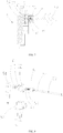
- an embodiment of the present invention provides an automatic cooking machine, which includes a base 11, a cooking pot 12 mounted on the base 11 and configured to load a food material, a pot lid 21 hinged to the base 11 and covering the cooking pot 12, a stirring mechanism 26 rotatably connected to the pot lid 21 and configured to stir the food material, a food material box 41, and a film tearing assembly 51 mounted on the pot lid;
- the cooking pot 12 is provided with a dish chamber 13 configured to store the food material;
- the stirring mechanism 26 includes a control arm 27 rotatably connected to the pot lid 21, a connecting arm 28 rotatably connected to the pot lid 21, and a stirring blade 29 disposed between the control arm 27 and the connecting arm 28;
- the control arm 27 and the connecting arm 28 have the same rotating axis;
- the stirring mechanism 26 rotates around the rotating axis;
- the stirring blade 29 rotates around the rotating axis, and stirs the food material in the dish chamber 13;
- the food material box 41 includes a box body 42 movably connected to
- a stirring chamber enclosed by the cooking pot and the pot lid is of a cylindrical shape, so that a corner of the cooking pot cannot contact the stirring blade may be prevented, and the utilization rate of the stirring chamber is improved.
- the pot lid 21 is opened; since the stirring blade 29 is mounted on the pot lid 21, the stirring blade 29 moves along with the pot lid 21 and the stirring blade 29 is separated from the cooking pot 12; as a result, the inconvenience brought by the stirring blade 29 in the dish putting process is prevented, and the dish putting efficiency of the cooking machine is greatly improved.
- the prepared food material and seasoning may be placed into the food material box 42, thereby improving the convenience of adding the food material to the automatic cooking machine.
- the film tearing rotating shaft 52 is driven by the power device 54 to rotate, and the hook 53 on the film tearing rotating shaft 52 hooks the hanging port 45 on the sealing film 44 to rotate and tear the sealing film 44; and meanwhile, the sealing film 44 drives the box body 42 to move toward the direction of the feeding port to feed the food material, and after the film is torn, the food material may be automatically fed into the cooking pot from the feeding port by means of its own gravity.
- the film tearing assembly 51 is simple in structure, and the sealing film 44 is torn through the rotation of the film tearing rotating shaft 52, so that the food material box is controlled conveniently to feed the food material; and moreover, as the tearing rotating shaft 52 drives the food material box 41 to move toward the feeding port during the rotating process, all food materials are prevented from being fed at a time, and thus the taste of dish is improved, and the user experience is good.
- an axis of the stirring chamber is parallel to the rotating axis, and an angle between the rotating axis and a horizontal plane ranges from 0° to 30°.
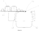
- the stirring blade 29 rotates to the bottom of the cooking pot 12 and may be in contact with a surface of the bottom; the stirring blade 29 may be slid along the surface of the bottom of the cooking pot 12; the stirring blade 29 forms an included angle with a normal plane that is perpendicular to the tangential plane at a contact point on the surface of the cooking pot 12; and the included angle is an acute angle.
- the stirring blade 29 of the cooking machine forms the acute angle with the normal plane at the contact position on the surface of the cooking pot 12, so that the food material may roll along the surface of the stirring blade 29 in the food material stirring process; the food material rolling into the cooking pot 12 from the surface of the stirring blade 29 may continuously roll over in a food material stirrer under the action of an inertia force and the action of continuous stirring of the stirring mechanism 26, so that each side of the food material absorbs the same amount of heat, and a phenomenon that the food material is not cooked thoroughly or is burnt is prevented; the stirring blade 29 may rotate to contact the surface of the cooking pot 12, so it is assured that all food materials on a surface of a container may be stirred by the stirring blade 29 during a re-stirring process, and thus the stirring effect of the stirring blade 29 is improved, and a situation in which some food materials are located in a gap between the stirring blade 29 and the surface of the cooking pot 12 and cannot be stirred to result in that the food materials are burnt is prevented.
- the control arm 27 includes a control arm body 27a, and a first rotating pin 27b disposed on a side portion of the control arm body 27a;
- the connecting arm 28 includes a connecting arm body 28a and a second rotating pin 28b disposed on a side portion of the connecting arm body 28a; the first rotating pin 27b and the second rotating pin 28b have a same rotating axis; one end of the stirring blade 29 is connected to the control arm body 27a, and the other end of the stirring blade 29 is connected to the connecting arm body 28a; and projections of the control arm 27, the connecting arm 28, and the stirring blade 29 are in fan-shaped distribution along a direction of the rotating axis.
- a portion where the stirring blade 29 is connected to the control arm 27 is set as a rounded corner, and a portion where the stirring blade 29 is connected to the connecting arm 28 is set as a rounded corner.
- the cooking pot 12 and the stirring mechanism 26 of the cooking machine need to be cleaned; the portion where the stirring blade 29 is connected to the control arm 27 is set as the rounded corner, and the portion where the stirring blade 29 is connected to the connecting arm 28 is set as the rounded corner, so that openings 24 at a junction of the stirring blade 29 and the control arm 27 and a junction of the stirring blade 29 and the connecting arm 28 may be larger, the convenience of cleaning of the stirring blade 29 is improved, and the maintenance of the cooking machine is convenient, and thus the service life of the cooking machine is prolonged.
- the pot lid 21 is provided with an accommodation chamber; an inner shell 23 is mounted in the accommodation chamber; the first rotating pin 27b is rotatably connected to the inner shell 23; the second rotating pin 28b is rotatably connected to the inner shell 23; and in the stirring chamber, the stirring blade 29 rotates around the rotating axis.
- the inner shell 23 is provided with a groove 25 having a major arc shape in cross-section; the stirring mechanism 26 rotates in the groove 25; a feeding port 22 is formed on a top of the pot lid 21; an opening 24 is formed on a top of the inner shell 23; and the opening 24 is matched with the feeding port 22 and the opening 24 communicates with the feeding port 22.
- the food material and the seasoning may be added to the cooking machine from the feeding port 22; moreover, the feeding port 22 is formed at the top, so that the lateral sealing property may be increased, and a soup is prevented from splashing from a side direction.
- the inner shell 23 arranged in the major arc, it is assured that a sufficient distance is kept between the feeding port 22 and the stirring blade 29, the soup is prevented from splashing from the feeding port 22 and scalding an operator of the cooking machine, and the safety of the cooking machine is enhanced.
- the heat loss may further be prevented, the frying speed of the food material is accelerated, and the efficiency of cooking the dish by the cooking machine is improved.
- a seal ring 30 configured to prevent a liquid from overflowing is disposed between the base 11 and the pot lid 21; and the seal ring 30 is fixedly mounted at an edge position of a lower end of the pot lid 21.
- the sealing property at a junction of the base 11 and the pot lid 21 may be strengthened, and when the cooking machine is used for cooking, the soup may be prevented from overflowing from the junction of the base 11 and the pot lid 21 to increase the cleaning workload of the cooking machine.
- the automatic cooking machine further includes a heating device disposed on the base 11 and configured to provide heat for the cooking machine; and the heating device is installed at a position below the cooking pot 12.
- the food material may be heated by the heating device during the stirring process, so that the shape of the food material is changed and nutritional components of a food are more easily absorbed by human body.
- the bottom of the cooking pot 12 has a minor arc shape in cross-section; a position on a side portion of the cooking pot 12 extends outward to form an extension portion 14 of a handle 15 for connection; the handle 15 configured to take the cooking pot 12 is mounted and connected at a free end of the extension portion 14; and the handle 15 is stretched out of an outer circumference of the base 11.
- the heating device located below the cooking pot 12 heats, as the bottom of the cooking pot 12 is arranged in the minor arc, the heat is uniformly distributed at the bottom of the cooking pot 12, and a situation that the heat is excessively concentrated at a certain position to burn the food material easily and the food material at other positions still is not completely cooked due to insufficient heat is prevented.
- the bottom of the cooking pot 12 is arranged in the minor arc, which is also beneficial to taking out a fried food material from the cooking pot 12; and by disposing the handle 15 out of the outer circumference of the base 11, the heating device may be prevented from heating the handle 15 to scald a hand in the heating process.
- the pot lid 21 further includes a hand grip 31 configured to close or open the pot lid 21 and the base 11; and the hand grip 31 is disposed outside the handle 15.
- a user may open the pot lid by the hand grip.
- the hand grip has the characteristic of being held conveniently, so the user applies an external force conveniently to open the pot lid, and thus the efficiency of opening the pot lid is improved.
- the temperature of the pot lid is too high. With the hand grip, the user may be prevented from directly touching the pot lid, thereby being beneficial to preventing the user from being scalded.
- a corner of the pot lid 21 and a corner of the base 11 in the cooking machine are rounded corners.
- Each corner of the cooking machine is set as the rounded corner, so that each corner of the cooking machine has a good buffer surface, and thus an operator may be prevented from being injured or scratched during the dish putting process, and the safety performance of the cooking machine is improved.
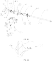
- the film tearing assembly 51 further includes a shaft sleeve part 55 connected to the film tearing rotating shaft 52, a clutch mechanism 59 connected to the power device 54, and a first fixing frame 63 connected to the pot lid 21 and configured to fix the shaft sleeve part 55 and the clutch mechanism 59; and the power device 54 drives the clutch mechanism 59 to rotate forwardly or reversely so that the clutch mechanism 59 is connected to or separated from the shaft sleeve part 55.
- the clutch mechanism 59 includes a clutch rotating shaft pin 60, a clutch nut 61 in threaded fit with the clutch rotating shaft pin 60, and a second fixing frame 62 configured to fix the clutch nut 61; and the second fixing frame 62 is mounted on the first fixing frame 63.
- the clutch nut 61 is a hexagonal nut.
- the power unit 54 in this embodiment is set as a deceleration motor.
- the deceleration motor is fixed on the first fixing frame 63, so it may be understood that the first fixing frame 63 may also be expressed as a motor assembly fixing frame.
- a shaft of the deceleration motor is connected into the clutch rotating shaft pin 60 to drive the clutch rotating shaft pin 60 to rotate forwardly or reversely;
- the clutch hexagonal nut is fixed on the second fixing frame 62, and the second fixing frame 62 is fixed on the first fixing frame 63; and an outer ring of the clutch rotating shaft pin 60 is provided with an external screw thread, and is matched with the hexagonal nut with an internal screw thread.
- the shaft sleeve part 55 includes an inner shaft sleeve 56 configured to fix the film tearing rotating shaft 52 and a movable shaft sleeve 57 assembled in the inner shaft sleeve 56 and configured to be connected to or separated from the clutch rotating shaft pin 60.
- a spring 58 is disposed between the inner shaft sleeve 56 and the movable shaft sleeve 57. It may be understood that the movable shaft sleeve 57 and the spring 58 are assembled in the inner shaft sleeve 56 together; the inner shaft sleeve 56 is connected to the film tearing rotating shaft 52, and the inner shaft sleeve 56 is fixed on the first fixing frame 63.
- the connection and the separation between the deceleration motor and the film tearing rotating shaft 52 are implemented. After the feeding is completed, the motor rotates reversely, and the film tearing rotating shaft 52 is separated from the clutch rotating shaft pin 60. A heat sealing film wound on the film tearing rotating shaft 52 may be manually pulled out to complete the withdrawal operation of the food material box 41.
- the box body 42 includes a plurality of sub-boxes 43 configured to place the food material; the plurality of sub-boxes 43 is independent of each other; the plurality of sub-boxes 43 is arranged side by side along a direction in which the box body 42 moves, thereby implementing segmented packaging of the food material; and by tearing the sealing film, the food material may be fallen out of the sub-boxes 43 to the cooking pot 12 to implement segmented feeding.
- each of the sub-boxes 43 may be configured to place different food materials; the box body 42 is sealed by the heat sealing film; and the hanging port 45 is formed at a front end of the sealing film 44.
- an infrared sensing module (not shown in the figure) configured to trigger and position the food material box 41 is disposed on the pot lid 21; and the infrared sensing module includes an infrared emitting module and an infrared receiving module.
- the power device 54 drives the film tearing rotating shaft 52 to rotate; the hook 53 of the film tearing rotating shaft 52 hooks the food material box 41; and then infrared triggering and positioning of the infrared sensing module are performed. It is noted that when the hook 53 of the film tearing rotating shaft 52 hooks the food material box 41, a manual or automatic manner may be selected according to an actual need.
- the deceleration motor is mounted on a side edge of the feeding port 22 of the pot lid 21, and the film tearing rotating shaft 52 is connected to the deceleration motor.
- the film tearing rotating shaft 52 is mounted on the feeding port 22 of the pot lid 21.
- an output torque of the deceleration motor ranges from 2 kgf.cm to 14 kgf.cm.
- a guide groove 21a in sliding fit with the food material box 41 is formed on the pot lid 21, and the feeding port 22 is formed at a tail end of the guide groove 21a.
- the infrared emitting module and the infrared receiving module are mounted at two sides of the guide groove 21a of the pot lid 21, and the food material box 41 is triggered and positioned in an infrared manner.
- the film tearing rotating shaft 52 is rotated by the motor.
- the food material box 41 is hooked, the food material box 41 is pre-tensioned until a first sub-box 43 of the food material box 41 blocks infrared rays so as to determine that the food material box 41 is in place.
- the hook 53 is preferably disposed on a middle portion of the film tearing rotating shaft 52 to hook the hanging port 45 of the food material box 41, and drive the box body 42 to move forward.
- the hanging port 45 of the food material box 41 corresponds to the position of the hook 53.
- the food material box 41 When in use, the food material box 41 is placed in the guide groove 21a of the pot lid 21; when the cooking device is started up, the motor of the film tearing assembly 51 drives the film tearing rotating shaft 52 to rotate, and the hook 53 is placed at the middle of the film tearing rotating shaft 52 to hook the food material box 41 until the infrared module determines that the food material box 41 is in place; after a cooking command is started, the film tearing rotating shaft 52 rotates to tear the sealing film 44 below the food material box 41 and wind the film on the shaft; at the same time, the box body 42 is driven to move in the direction toward the opening 24 and the feeding port 22 along the guide groove 21a, so that the food material is automatically fed into the cooking pot from the feeding port under its own gravity.
- the deceleration motor rotates reversely first, the deceleration motor is separated from the film tearing rotating shaft 52, and the film tearing rotating shaft 52 may rotate freely.
- the withdrawal operation of the food material box 41 may be completed by manually pulling out the heat sealing film wound on the film tearing rotating shaft 52 and the box body 42.
- the automatic film tearing and feeding may be implemented for the well prepared food material box 41; and all food materials are prevented from being fed at a time, and thus the taste of the dish is improved, and the user experience is good.
- the automatic cooking machine provided by the present invention is configured to automatically feed the food material, and may be used in a cooking machine, a stirrer and a food processor, but is not limited thereto.
- a pin 541 is cooperatively provided on an output shaft of a power device 54.
- the other end of the pin 541 is connected to a clutch mechanism 59 to transmit a rotational power of the power device 54 to the clutch mechanism 59.
- the rotational power is transmitted to the clutch mechanism 59 more smoothly; and meanwhile, a sliding friction resistance with the clutch mechanism 59 is greatly reduced.
- a transmission manner adopted in the prior art is usually a flat-position manner and has the defects of large friction and easy blockage.
- one end, matched with the output shaft of the power device 54, of the clutch rotating shaft pin 60 is provided with a notch 5411 that is matched with the pin 541 one another; and a guide cylinder 5412 is further disposed at the other end of the clutch rotating shaft pin 60.
- a diameter of the guide cylinder 5412 is 2-4 mm, and the diameter of the guide cylinder 5412 may be any value within 2-4 mm.
- the diameter of the guide cylinder 5412 may be 2 mm, 3 mm or 4mm, and preferably is 3 mm.
- the hook 53 includes a penetrating rod 5211 that is disposed on the film tearing rotating shaft 52 in a penetration manner.
- a hanging groove 5212 is formed on an end portion of the penetrating rod 5211.
Landscapes
- Engineering & Computer Science (AREA)
- Food Science & Technology (AREA)
- Manufacturing & Machinery (AREA)
- Mechanical Engineering (AREA)
- Food-Manufacturing Devices (AREA)
- Cookers (AREA)
- Frying-Pans Or Fryers (AREA)
Priority Applications (1)
| Application Number | Priority Date | Filing Date | Title |
|---|---|---|---|
| PL17909811T PL3485768T3 (pl) | 2017-05-19 | 2017-08-28 | Zautomatyzowana maszyna do smażenia z mieszaniem |
Applications Claiming Priority (2)
| Application Number | Priority Date | Filing Date | Title |
|---|---|---|---|
| CN201710356677.2A CN107048981B (zh) | 2017-05-19 | 2017-05-19 | 自动炒菜机 |
| PCT/CN2017/099284 WO2018209839A1 (zh) | 2017-05-19 | 2017-08-28 | 自动炒菜机 |
Publications (3)
| Publication Number | Publication Date |
|---|---|
| EP3485768A1 EP3485768A1 (en) | 2019-05-22 |
| EP3485768A4 EP3485768A4 (en) | 2020-03-18 |
| EP3485768B1 true EP3485768B1 (en) | 2021-05-12 |
Family
ID=59609418
Family Applications (1)
| Application Number | Title | Priority Date | Filing Date |
|---|---|---|---|
| EP17909811.6A Active EP3485768B1 (en) | 2017-05-19 | 2017-08-28 | Automated stir frying machine |
Country Status (9)
| Country | Link |
|---|---|
| US (1) | US10986957B2 (pl) |
| EP (1) | EP3485768B1 (pl) |
| JP (1) | JP6640424B2 (pl) |
| CN (1) | CN107048981B (pl) |
| ES (1) | ES2883649T3 (pl) |
| PL (1) | PL3485768T3 (pl) |
| SG (1) | SG11201811825PA (pl) |
| TW (1) | TWI650098B (pl) |
| WO (1) | WO2018209839A1 (pl) |
Families Citing this family (47)
| Publication number | Priority date | Publication date | Assignee | Title |
|---|---|---|---|---|
| CN106913257B (zh) * | 2017-03-23 | 2018-11-02 | 深圳饭来科技有限公司 | 撕膜投料机构 |
| CN107048981B (zh) * | 2017-05-19 | 2019-02-22 | 深圳饭来科技有限公司 | 自动炒菜机 |
| CN107581894A (zh) * | 2017-10-30 | 2018-01-16 | 苏州西顿家用自动化有限公司 | 一种自动烹饪设备 |
| CN107581895A (zh) * | 2017-10-30 | 2018-01-16 | 苏州西顿家用自动化有限公司 | 一种自动炒菜机撕膜机构 |
| CN107874591B (zh) * | 2017-11-29 | 2023-01-24 | 浙江爱仕达生活电器有限公司 | 一种用于自动炒菜机的食材盒 |
| CN109864618B (zh) * | 2017-12-01 | 2024-01-16 | 宁波方太厨具有限公司 | 一种料理机 |
| CN107856935A (zh) * | 2017-12-05 | 2018-03-30 | 东莞市欣能电器有限公司 | 撕膜收卷装置 |
| CN110037531B (zh) * | 2018-01-16 | 2024-04-26 | 李亚锐 | 一种投料装置及烹调机 |
| CN108209594A (zh) * | 2018-01-29 | 2018-06-29 | 宁波欧琳厨具有限公司 | 一种智能搅拌烧菜装置 |
| CN110097151B (zh) * | 2018-01-31 | 2023-05-26 | 李亚锐 | 一种智能盛菜装置及其烹调机 |
| CN113349626A (zh) * | 2018-02-02 | 2021-09-07 | 李亚锐 | 一种烹调机 |
| CN108477975A (zh) * | 2018-05-30 | 2018-09-04 | 李锐 | 一次性供料全自动炒菜机 |
| CN109091015B (zh) * | 2018-08-24 | 2024-06-21 | 深圳英诺智慧科技有限公司 | 一种炒菜机的挡雾板 |
| CN108703641A (zh) * | 2018-08-24 | 2018-10-26 | 深圳英诺智慧科技有限公司 | 一种与物料盒配合的自动炒菜机 |
| CN108836123A (zh) * | 2018-09-12 | 2018-11-20 | 北京故亭科技有限公司 | 一种智能料理机的搅拌装置 |
| CN111345668A (zh) * | 2018-12-21 | 2020-06-30 | 苏州西顿家用自动化有限公司 | 自动炒菜机的自动加料机构 |
| CN111358302A (zh) * | 2018-12-25 | 2020-07-03 | 九阳股份有限公司 | 一种用于炒菜机的铝箔盒 |
| CN109691871A (zh) * | 2018-12-31 | 2019-04-30 | 广州富港万嘉智能科技有限公司 | 自动炒菜机及炒菜与蒸菜一体烹饪机 |
| CN111489498B (zh) * | 2019-01-25 | 2022-05-27 | 深圳御膳坊智能科技有限公司 | 一种带冷藏输送的智能厨房 |
| CN111481062A (zh) * | 2019-01-25 | 2020-08-04 | 东莞御膳坊信息技术有限公司 | 一种智能炒菜机的食材盒定位及撕膜机构及其炒菜机 |
| CN109846369B (zh) * | 2019-02-20 | 2023-10-03 | 广东德琪电器实业有限公司 | 一种自动炒菜机 |
| CN109846372A (zh) * | 2019-03-31 | 2019-06-07 | 佛山市方块工业设计有限公司 | 一种全自动炒菜机的锅盖 |
| CN109875383B (zh) * | 2019-03-31 | 2024-02-09 | 佛山市方块工业设计有限公司 | 一种全自动炒菜机 |
| USD982375S1 (en) | 2019-06-06 | 2023-04-04 | Sharkninja Operating Llc | Food preparation device |
| CN110279285B (zh) * | 2019-06-06 | 2025-03-25 | 深圳饭来科技有限公司 | 自动投料机构及智能烹饪装置 |
| CN110179325A (zh) * | 2019-07-03 | 2019-08-30 | 四川长虹智能制造技术有限公司 | 一种炒菜机 |
| CN110477780B (zh) * | 2019-08-15 | 2024-11-22 | 袁庆宏 | 盛料盒及作用盛料盒的撕膜投料装置 |
| CN110720822B (zh) * | 2019-12-04 | 2021-03-12 | 北京我是大厨科技有限公司 | 全自动模块料理机及其控制方法 |
| CN110973983B (zh) * | 2019-12-31 | 2025-06-24 | 深圳市繁兴技术服务有限公司 | 烹饪设备 |
| CN113116180B (zh) * | 2020-01-16 | 2023-04-14 | 广东美的白色家电技术创新中心有限公司 | 料理机 |
| CN113142969A (zh) * | 2020-01-23 | 2021-07-23 | 刘英杰 | 自动炒菜机顶盖及自动炒菜机 |
| CN111202442A (zh) * | 2020-02-28 | 2020-05-29 | 中山市绿航电器有限公司 | 一种食材加工装置 |
| CN113243765B (zh) * | 2020-06-11 | 2022-10-11 | 杭州九阳小家电有限公司 | 一种翻转投料式炒菜机 |
| CN113807108B (zh) * | 2020-06-11 | 2023-07-18 | 杭州九阳小家电有限公司 | 一种炒菜机的料盒识别方法 |
| CN111713981A (zh) * | 2020-07-17 | 2020-09-29 | 四川长虹电子控股集团有限公司 | 一种投料装置和炒菜机 |
| CN112386093A (zh) * | 2020-10-23 | 2021-02-23 | 湖南邦福农业综合开发有限公司 | 一种煮饭分饭设备 |
| CN112426013B (zh) * | 2020-11-06 | 2025-10-14 | 广东万家乐燃气具有限公司 | 炒菜颠锅装置及其仿真控制方法 |
| CN112386138B (zh) * | 2020-11-19 | 2022-02-15 | 深圳御膳坊智能科技有限公司 | 一种基于智能厨房系统的食材加工方法和智能厨房系统 |
| CN114680674A (zh) * | 2020-12-25 | 2022-07-01 | 浙江绍兴苏泊尔生活电器有限公司 | 烹饪器具的控制方法及烹饪器具 |
| CN113353411A (zh) * | 2020-12-30 | 2021-09-07 | 广州富港万嘉智能科技有限公司 | 组合型食物盒和智能橱柜 |
| CN113229706A (zh) * | 2021-06-02 | 2021-08-10 | 杭州板牙科技有限公司 | 一种熔融式的炒菜机撕膜机构 |
| JP7825115B2 (ja) * | 2021-06-24 | 2026-03-06 | パナソニックIpマネジメント株式会社 | 加熱調理器 |
| CN114081336A (zh) * | 2021-09-08 | 2022-02-25 | 深圳御膳坊智能科技有限公司 | 一种智能炒菜机器人 |
| CN115429115B (zh) * | 2022-04-14 | 2026-04-07 | 深圳拓邦股份有限公司 | 一种烹饪设备的搅拌轨迹获取方法、搅拌头及烹饪设备 |
| CN116461807A (zh) * | 2023-04-27 | 2023-07-21 | 原子舞动(北京)科技有限公司 | 撕膜装置、撕膜装置的撕膜方法及烹饪设备 |
| CN116530821A (zh) * | 2023-05-23 | 2023-08-04 | 原子舞动(北京)科技有限公司 | 烹饪设备 |
| CN116807241B (zh) * | 2023-07-14 | 2025-08-26 | 乐歌人体工学科技股份有限公司 | 用于自动炒菜机的切膜投料装置 |
Family Cites Families (24)
| Publication number | Priority date | Publication date | Assignee | Title |
|---|---|---|---|---|
| JPS5035957Y2 (pl) * | 1972-10-13 | 1975-10-20 | ||
| JP3504341B2 (ja) * | 1994-08-03 | 2004-03-08 | 有限会社飯田製作所 | 蒸練機の撹拌羽根 |
| CN100413438C (zh) | 2002-05-31 | 2008-08-27 | 深圳市爱可机器人技术有限公司 | 物料自动投放系统、其所用物料包装以及相应的烹调器具 |
| AU2003242176A1 (en) * | 2002-05-31 | 2003-12-19 | Xiaoyong Liu | Automatic food cooking apparatus |
| ITMI20021794A1 (it) * | 2002-08-06 | 2004-02-07 | Techfood S N C Di Iori E Castagnetti | Macchina automatica per la cottura di pasta all'italiana |
| JP2004121542A (ja) * | 2002-10-02 | 2004-04-22 | Matsushita Electric Ind Co Ltd | 自動製パン機 |
| ATE428334T1 (de) * | 2003-10-17 | 2009-05-15 | Xiaoyong Liu | Intelligentes garverfahren |
| CN100479720C (zh) * | 2006-02-22 | 2009-04-22 | 深圳市爱可机器人技术有限公司 | 烹饪设备的自动投料装置 |
| CN101637353B (zh) * | 2008-07-30 | 2013-03-13 | 深圳市爱可机器人技术有限公司 | 烹调设备 |
| TWI442898B (zh) * | 2010-02-09 | 2014-07-01 | Sanyo Electric Co | 自動製麵包機 |
| PL2637532T3 (pl) * | 2010-11-09 | 2016-07-29 | La Vit Tech Llc | Kapsułkowy układ sporządzania i wydawania napojów |
| CN102090839B (zh) * | 2010-12-03 | 2012-09-05 | 乔林友 | 自动控制的炒锅 |
| CN103251302B (zh) * | 2012-02-16 | 2015-10-07 | 周林斌 | 搅拌器能驱动微动开关的多功能炒锅 |
| CN102973163A (zh) * | 2012-09-19 | 2013-03-20 | 漳州灿坤实业有限公司 | 一种面包自动制作机、面包原料盒和面包的快捷制作方法 |
| CN204158228U (zh) | 2014-09-04 | 2015-02-18 | 张岩 | 投料盒 |
| US20160278567A1 (en) * | 2015-03-27 | 2016-09-29 | Marc Gagnon | Automated Immersion Apparatus and Method for Cooking Meals |
| CN106343878B (zh) * | 2015-07-14 | 2018-06-01 | 合肥道卓科技有限公司 | 一种智能烹饪装置的固体物料投料系统 |
| CN105411362B (zh) * | 2015-12-03 | 2018-10-09 | 深圳饭来科技有限公司 | 自动烹饪机 |
| CN105496180B (zh) | 2016-01-27 | 2018-05-01 | 张利军 | 一种全自动炒菜机 |
| CN105496218B (zh) * | 2016-02-02 | 2017-10-10 | 眉山华辰科技有限公司 | 智能炒菜机自动下料机构 |
| CN206006864U (zh) * | 2016-06-08 | 2017-03-15 | 欣尚韬 | 一种自动烹调炒菜锅 |
| CN106108728A (zh) | 2016-07-06 | 2016-11-16 | 李峰 | 一种全自动家用烹饪机 |
| CN106428854B (zh) * | 2016-10-27 | 2019-06-25 | 怀化夯美科技有限公司 | 料盒的撕膜方法、撕膜装置及烹饪机自动投料装置 |
| CN107048981B (zh) * | 2017-05-19 | 2019-02-22 | 深圳饭来科技有限公司 | 自动炒菜机 |
-
2017
- 2017-05-19 CN CN201710356677.2A patent/CN107048981B/zh active Active
- 2017-08-28 SG SG11201811825PA patent/SG11201811825PA/en unknown
- 2017-08-28 PL PL17909811T patent/PL3485768T3/pl unknown
- 2017-08-28 EP EP17909811.6A patent/EP3485768B1/en active Active
- 2017-08-28 WO PCT/CN2017/099284 patent/WO2018209839A1/zh not_active Ceased
- 2017-08-28 ES ES17909811T patent/ES2883649T3/es active Active
- 2017-08-28 US US16/317,544 patent/US10986957B2/en not_active Expired - Fee Related
- 2017-08-28 JP JP2019502068A patent/JP6640424B2/ja not_active Expired - Fee Related
-
2018
- 2018-02-13 TW TW107105308A patent/TWI650098B/zh not_active IP Right Cessation
Non-Patent Citations (1)
| Title |
|---|
| None * |
Also Published As
| Publication number | Publication date |
|---|---|
| TWI650098B (zh) | 2019-02-11 |
| JP2019524248A (ja) | 2019-09-05 |
| JP6640424B2 (ja) | 2020-02-05 |
| EP3485768A4 (en) | 2020-03-18 |
| TW201900087A (zh) | 2019-01-01 |
| US20190290059A1 (en) | 2019-09-26 |
| WO2018209839A1 (zh) | 2018-11-22 |
| PL3485768T3 (pl) | 2021-11-22 |
| ES2883649T3 (es) | 2021-12-09 |
| SG11201811825PA (en) | 2019-01-30 |
| CN107048981B (zh) | 2019-02-22 |
| US10986957B2 (en) | 2021-04-27 |
| CN107048981A (zh) | 2017-08-18 |
| EP3485768A1 (en) | 2019-05-22 |
Similar Documents
| Publication | Publication Date | Title |
|---|---|---|
| US10986957B2 (en) | Automatic cooking machine | |
| CN108601478B (zh) | 一种上置式搅拌炒菜机 | |
| WO2018171121A1 (zh) | 撕膜投料机构 | |
| CN207544864U (zh) | 自动炒菜机 | |
| CN205758381U (zh) | 一种多功能智能厨师机 | |
| CN203354373U (zh) | 多功能面包机 | |
| CN207266701U (zh) | 一种空气炸锅 | |
| WO2017197822A1 (zh) | 一种多功能智能厨师机 | |
| KR102088168B1 (ko) | 냄비의 뚜껑에 결합되는 교반기 | |
| CN214284458U (zh) | 锅盖组件及烹饪器具 | |
| CN109864550B (zh) | 一种炒菜料理机及其炒菜控制方法 | |
| KR102088176B1 (ko) | 냄비의 뚜껑에 결합된 교반기 | |
| CN202723616U (zh) | 自动制面包机 | |
| CN203814557U (zh) | 炒果机的翻转翻炒机构 | |
| CN213075417U (zh) | 一种倾斜滚筒式自动炒菜机 | |
| CN211961725U (zh) | 烹饪器具 | |
| HK1242929A1 (en) | Automatic cooker | |
| HK1242929A (en) | Automatic cooker | |
| KR102088174B1 (ko) | 교반기 및 교반기가 결합된 냄비 | |
| KR102158929B1 (ko) | 음식 가열 장치 | |
| CN109864553A (zh) | 一种炒菜料理机及其炒菜控制方法 | |
| HK1242929B (zh) | 自动炒菜机 | |
| CN210018907U (zh) | 一种蒸煮器 | |
| CN111670919A (zh) | 一种自动翻转炸制锅具 | |
| CN219680437U (zh) | 一种送菜机构 |
Legal Events
| Date | Code | Title | Description |
|---|---|---|---|
| STAA | Information on the status of an ep patent application or granted ep patent |
Free format text: STATUS: THE INTERNATIONAL PUBLICATION HAS BEEN MADE |
|
| PUAI | Public reference made under article 153(3) epc to a published international application that has entered the european phase |
Free format text: ORIGINAL CODE: 0009012 |
|
| STAA | Information on the status of an ep patent application or granted ep patent |
Free format text: STATUS: REQUEST FOR EXAMINATION WAS MADE |
|
| 17P | Request for examination filed |
Effective date: 20190111 |
|
| AK | Designated contracting states |
Kind code of ref document: A1 Designated state(s): AL AT BE BG CH CY CZ DE DK EE ES FI FR GB GR HR HU IE IS IT LI LT LU LV MC MK MT NL NO PL PT RO RS SE SI SK SM TR |
|
| AX | Request for extension of the european patent |
Extension state: BA ME |
|
| A4 | Supplementary search report drawn up and despatched |
Effective date: 20200213 |
|
| RIC1 | Information provided on ipc code assigned before grant |
Ipc: A47J 27/00 20060101ALI20200207BHEP Ipc: A47J 36/00 20060101ALI20200207BHEP Ipc: A47J 36/16 20060101ALI20200207BHEP Ipc: A47J 36/06 20060101ALI20200207BHEP Ipc: A21B 7/00 20060101ALN20200207BHEP Ipc: A47J 43/04 20060101AFI20200207BHEP |
|
| DAV | Request for validation of the european patent (deleted) | ||
| DAX | Request for extension of the european patent (deleted) | ||
| REG | Reference to a national code |
Ref country code: DE Ref legal event code: R079 Ref document number: 602017038676 Country of ref document: DE Free format text: PREVIOUS MAIN CLASS: A47J0027000000 Ipc: A47J0043040000 |
|
| GRAP | Despatch of communication of intention to grant a patent |
Free format text: ORIGINAL CODE: EPIDOSNIGR1 |
|
| STAA | Information on the status of an ep patent application or granted ep patent |
Free format text: STATUS: GRANT OF PATENT IS INTENDED |
|
| RIC1 | Information provided on ipc code assigned before grant |
Ipc: A47J 27/00 20060101ALI20201120BHEP Ipc: A47J 36/16 20060101ALI20201120BHEP Ipc: A47J 43/04 20060101AFI20201120BHEP Ipc: A47J 36/06 20060101ALI20201120BHEP Ipc: A47J 36/00 20060101ALI20201120BHEP Ipc: A21B 7/00 20060101ALN20201120BHEP |
|
| INTG | Intention to grant announced |
Effective date: 20201209 |
|
| GRAS | Grant fee paid |
Free format text: ORIGINAL CODE: EPIDOSNIGR3 |
|
| GRAA | (expected) grant |
Free format text: ORIGINAL CODE: 0009210 |
|
| STAA | Information on the status of an ep patent application or granted ep patent |
Free format text: STATUS: THE PATENT HAS BEEN GRANTED |
|
| AK | Designated contracting states |
Kind code of ref document: B1 Designated state(s): AL AT BE BG CH CY CZ DE DK EE ES FI FR GB GR HR HU IE IS IT LI LT LU LV MC MK MT NL NO PL PT RO RS SE SI SK SM TR |
|
| REG | Reference to a national code |
Ref country code: GB Ref legal event code: FG4D |
|
| REG | Reference to a national code |
Ref country code: CH Ref legal event code: EP |
|
| REG | Reference to a national code |
Ref country code: DE Ref legal event code: R096 Ref document number: 602017038676 Country of ref document: DE |
|
| REG | Reference to a national code |
Ref country code: IE Ref legal event code: FG4D |
|
| REG | Reference to a national code |
Ref country code: AT Ref legal event code: REF Ref document number: 1391600 Country of ref document: AT Kind code of ref document: T Effective date: 20210615 |
|
| REG | Reference to a national code |
Ref country code: NL Ref legal event code: FP |
|
| REG | Reference to a national code |
Ref country code: SE Ref legal event code: TRGR |
|
| REG | Reference to a national code |
Ref country code: LT Ref legal event code: MG9D |
|
| PGFP | Annual fee paid to national office [announced via postgrant information from national office to epo] |
Ref country code: NL Payment date: 20210830 Year of fee payment: 5 |
|
| PG25 | Lapsed in a contracting state [announced via postgrant information from national office to epo] |
Ref country code: FI Free format text: LAPSE BECAUSE OF FAILURE TO SUBMIT A TRANSLATION OF THE DESCRIPTION OR TO PAY THE FEE WITHIN THE PRESCRIBED TIME-LIMIT Effective date: 20210512 Ref country code: LT Free format text: LAPSE BECAUSE OF FAILURE TO SUBMIT A TRANSLATION OF THE DESCRIPTION OR TO PAY THE FEE WITHIN THE PRESCRIBED TIME-LIMIT Effective date: 20210512 Ref country code: HR Free format text: LAPSE BECAUSE OF FAILURE TO SUBMIT A TRANSLATION OF THE DESCRIPTION OR TO PAY THE FEE WITHIN THE PRESCRIBED TIME-LIMIT Effective date: 20210512 Ref country code: BG Free format text: LAPSE BECAUSE OF FAILURE TO SUBMIT A TRANSLATION OF THE DESCRIPTION OR TO PAY THE FEE WITHIN THE PRESCRIBED TIME-LIMIT Effective date: 20210812 |
|
| PGFP | Annual fee paid to national office [announced via postgrant information from national office to epo] |
Ref country code: IT Payment date: 20210830 Year of fee payment: 5 Ref country code: FR Payment date: 20210830 Year of fee payment: 5 |
|
| PG25 | Lapsed in a contracting state [announced via postgrant information from national office to epo] |
Ref country code: GR Free format text: LAPSE BECAUSE OF FAILURE TO SUBMIT A TRANSLATION OF THE DESCRIPTION OR TO PAY THE FEE WITHIN THE PRESCRIBED TIME-LIMIT Effective date: 20210813 Ref country code: IS Free format text: LAPSE BECAUSE OF FAILURE TO SUBMIT A TRANSLATION OF THE DESCRIPTION OR TO PAY THE FEE WITHIN THE PRESCRIBED TIME-LIMIT Effective date: 20210912 Ref country code: PT Free format text: LAPSE BECAUSE OF FAILURE TO SUBMIT A TRANSLATION OF THE DESCRIPTION OR TO PAY THE FEE WITHIN THE PRESCRIBED TIME-LIMIT Effective date: 20210913 Ref country code: LV Free format text: LAPSE BECAUSE OF FAILURE TO SUBMIT A TRANSLATION OF THE DESCRIPTION OR TO PAY THE FEE WITHIN THE PRESCRIBED TIME-LIMIT Effective date: 20210512 Ref country code: NO Free format text: LAPSE BECAUSE OF FAILURE TO SUBMIT A TRANSLATION OF THE DESCRIPTION OR TO PAY THE FEE WITHIN THE PRESCRIBED TIME-LIMIT Effective date: 20210812 Ref country code: RS Free format text: LAPSE BECAUSE OF FAILURE TO SUBMIT A TRANSLATION OF THE DESCRIPTION OR TO PAY THE FEE WITHIN THE PRESCRIBED TIME-LIMIT Effective date: 20210512 |
|
| PGFP | Annual fee paid to national office [announced via postgrant information from national office to epo] |
Ref country code: BE Payment date: 20210830 Year of fee payment: 5 Ref country code: GB Payment date: 20210830 Year of fee payment: 5 Ref country code: TR Payment date: 20210827 Year of fee payment: 5 Ref country code: SE Payment date: 20210830 Year of fee payment: 5 Ref country code: DE Payment date: 20210830 Year of fee payment: 5 |
|
| REG | Reference to a national code |
Ref country code: ES Ref legal event code: FG2A Ref document number: 2883649 Country of ref document: ES Kind code of ref document: T3 Effective date: 20211209 |
|
| PG25 | Lapsed in a contracting state [announced via postgrant information from national office to epo] |
Ref country code: EE Free format text: LAPSE BECAUSE OF FAILURE TO SUBMIT A TRANSLATION OF THE DESCRIPTION OR TO PAY THE FEE WITHIN THE PRESCRIBED TIME-LIMIT Effective date: 20210512 Ref country code: SM Free format text: LAPSE BECAUSE OF FAILURE TO SUBMIT A TRANSLATION OF THE DESCRIPTION OR TO PAY THE FEE WITHIN THE PRESCRIBED TIME-LIMIT Effective date: 20210512 Ref country code: SK Free format text: LAPSE BECAUSE OF FAILURE TO SUBMIT A TRANSLATION OF THE DESCRIPTION OR TO PAY THE FEE WITHIN THE PRESCRIBED TIME-LIMIT Effective date: 20210512 Ref country code: RO Free format text: LAPSE BECAUSE OF FAILURE TO SUBMIT A TRANSLATION OF THE DESCRIPTION OR TO PAY THE FEE WITHIN THE PRESCRIBED TIME-LIMIT Effective date: 20210512 Ref country code: DK Free format text: LAPSE BECAUSE OF FAILURE TO SUBMIT A TRANSLATION OF THE DESCRIPTION OR TO PAY THE FEE WITHIN THE PRESCRIBED TIME-LIMIT Effective date: 20210512 Ref country code: CZ Free format text: LAPSE BECAUSE OF FAILURE TO SUBMIT A TRANSLATION OF THE DESCRIPTION OR TO PAY THE FEE WITHIN THE PRESCRIBED TIME-LIMIT Effective date: 20210512 |
|
| PGFP | Annual fee paid to national office [announced via postgrant information from national office to epo] |
Ref country code: ES Payment date: 20211026 Year of fee payment: 5 |
|
| REG | Reference to a national code |
Ref country code: DE Ref legal event code: R097 Ref document number: 602017038676 Country of ref document: DE |
|
| PLBE | No opposition filed within time limit |
Free format text: ORIGINAL CODE: 0009261 |
|
| STAA | Information on the status of an ep patent application or granted ep patent |
Free format text: STATUS: NO OPPOSITION FILED WITHIN TIME LIMIT |
|
| REG | Reference to a national code |
Ref country code: CH Ref legal event code: PL |
|
| PG25 | Lapsed in a contracting state [announced via postgrant information from national office to epo] |
Ref country code: MC Free format text: LAPSE BECAUSE OF FAILURE TO SUBMIT A TRANSLATION OF THE DESCRIPTION OR TO PAY THE FEE WITHIN THE PRESCRIBED TIME-LIMIT Effective date: 20210512 |
|
| PGFP | Annual fee paid to national office [announced via postgrant information from national office to epo] |
Ref country code: PL Payment date: 20210826 Year of fee payment: 5 |
|
| 26N | No opposition filed |
Effective date: 20220215 |
|
| PG25 | Lapsed in a contracting state [announced via postgrant information from national office to epo] |
Ref country code: LI Free format text: LAPSE BECAUSE OF NON-PAYMENT OF DUE FEES Effective date: 20210831 Ref country code: CH Free format text: LAPSE BECAUSE OF NON-PAYMENT OF DUE FEES Effective date: 20210831 |
|
| PG25 | Lapsed in a contracting state [announced via postgrant information from national office to epo] |
Ref country code: IS Free format text: LAPSE BECAUSE OF FAILURE TO SUBMIT A TRANSLATION OF THE DESCRIPTION OR TO PAY THE FEE WITHIN THE PRESCRIBED TIME-LIMIT Effective date: 20210912 Ref country code: LU Free format text: LAPSE BECAUSE OF NON-PAYMENT OF DUE FEES Effective date: 20210828 Ref country code: AL Free format text: LAPSE BECAUSE OF FAILURE TO SUBMIT A TRANSLATION OF THE DESCRIPTION OR TO PAY THE FEE WITHIN THE PRESCRIBED TIME-LIMIT Effective date: 20210512 |
|
| PG25 | Lapsed in a contracting state [announced via postgrant information from national office to epo] |
Ref country code: IE Free format text: LAPSE BECAUSE OF NON-PAYMENT OF DUE FEES Effective date: 20210828 |
|
| REG | Reference to a national code |
Ref country code: DE Ref legal event code: R119 Ref document number: 602017038676 Country of ref document: DE |
|
| REG | Reference to a national code |
Ref country code: SE Ref legal event code: EUG |
|
| REG | Reference to a national code |
Ref country code: NL Ref legal event code: MM Effective date: 20220901 |
|
| GBPC | Gb: european patent ceased through non-payment of renewal fee |
Effective date: 20220828 |
|
| PG25 | Lapsed in a contracting state [announced via postgrant information from national office to epo] |
Ref country code: SE Free format text: LAPSE BECAUSE OF NON-PAYMENT OF DUE FEES Effective date: 20220829 |
|
| REG | Reference to a national code |
Ref country code: BE Ref legal event code: MM Effective date: 20220831 |
|
| PG25 | Lapsed in a contracting state [announced via postgrant information from national office to epo] |
Ref country code: NL Free format text: LAPSE BECAUSE OF NON-PAYMENT OF DUE FEES Effective date: 20220901 Ref country code: CY Free format text: LAPSE BECAUSE OF FAILURE TO SUBMIT A TRANSLATION OF THE DESCRIPTION OR TO PAY THE FEE WITHIN THE PRESCRIBED TIME-LIMIT Effective date: 20210512 |
|
| PG25 | Lapsed in a contracting state [announced via postgrant information from national office to epo] |
Ref country code: IT Free format text: LAPSE BECAUSE OF NON-PAYMENT OF DUE FEES Effective date: 20220828 Ref country code: HU Free format text: LAPSE BECAUSE OF FAILURE TO SUBMIT A TRANSLATION OF THE DESCRIPTION OR TO PAY THE FEE WITHIN THE PRESCRIBED TIME-LIMIT; INVALID AB INITIO Effective date: 20170828 Ref country code: FR Free format text: LAPSE BECAUSE OF NON-PAYMENT OF DUE FEES Effective date: 20220831 Ref country code: DE Free format text: LAPSE BECAUSE OF NON-PAYMENT OF DUE FEES Effective date: 20230301 |
|
| PG25 | Lapsed in a contracting state [announced via postgrant information from national office to epo] |
Ref country code: BE Free format text: LAPSE BECAUSE OF NON-PAYMENT OF DUE FEES Effective date: 20220831 |
|
| REG | Reference to a national code |
Ref country code: ES Ref legal event code: FD2A Effective date: 20230929 |
|
| REG | Reference to a national code |
Ref country code: AT Ref legal event code: MM01 Ref document number: 1391600 Country of ref document: AT Kind code of ref document: T Effective date: 20220828 |
|
| PG25 | Lapsed in a contracting state [announced via postgrant information from national office to epo] |
Ref country code: GB Free format text: LAPSE BECAUSE OF NON-PAYMENT OF DUE FEES Effective date: 20220828 Ref country code: ES Free format text: LAPSE BECAUSE OF NON-PAYMENT OF DUE FEES Effective date: 20220829 Ref country code: AT Free format text: LAPSE BECAUSE OF NON-PAYMENT OF DUE FEES Effective date: 20220828 |
|
| PG25 | Lapsed in a contracting state [announced via postgrant information from national office to epo] |
Ref country code: MK Free format text: LAPSE BECAUSE OF FAILURE TO SUBMIT A TRANSLATION OF THE DESCRIPTION OR TO PAY THE FEE WITHIN THE PRESCRIBED TIME-LIMIT Effective date: 20210512 |
|
| PG25 | Lapsed in a contracting state [announced via postgrant information from national office to epo] |
Ref country code: PL Free format text: LAPSE BECAUSE OF NON-PAYMENT OF DUE FEES Effective date: 20220828 |
|
| PG25 | Lapsed in a contracting state [announced via postgrant information from national office to epo] |
Ref country code: TR Free format text: LAPSE BECAUSE OF NON-PAYMENT OF DUE FEES Effective date: 20220828 Ref country code: MT Free format text: LAPSE BECAUSE OF FAILURE TO SUBMIT A TRANSLATION OF THE DESCRIPTION OR TO PAY THE FEE WITHIN THE PRESCRIBED TIME-LIMIT Effective date: 20210512 |