EP3439065A1 - Materialien für elektronische vorrichtungen - Google Patents
Materialien für elektronische vorrichtungen Download PDFInfo
- Publication number
- EP3439065A1 EP3439065A1 EP18194164.2A EP18194164A EP3439065A1 EP 3439065 A1 EP3439065 A1 EP 3439065A1 EP 18194164 A EP18194164 A EP 18194164A EP 3439065 A1 EP3439065 A1 EP 3439065A1
- Authority
- EP
- European Patent Office
- Prior art keywords
- group
- radicals
- substituted
- atoms
- groups
- Prior art date
- Legal status (The legal status is an assumption and is not a legal conclusion. Google has not performed a legal analysis and makes no representation as to the accuracy of the status listed.)
- Granted
Links
- 0 CCNN=C1c2nnnnc2*C1=NN=C*(*)* Chemical compound CCNN=C1c2nnnnc2*C1=NN=C*(*)* 0.000 description 17
- IXGUSWAVGDEUMP-UHFFFAOYSA-N CC1(C)c(ccc(N(c2ccc(-c3ccc(N(c4ccccc4)c4ccccc4)[s]3)[s]2)c(cc2)ccc2-c2ccccc2)c2)c2-c2ccccc12 Chemical compound CC1(C)c(ccc(N(c2ccc(-c3ccc(N(c4ccccc4)c4ccccc4)[s]3)[s]2)c(cc2)ccc2-c2ccccc2)c2)c2-c2ccccc12 IXGUSWAVGDEUMP-UHFFFAOYSA-N 0.000 description 1
- NJGLVOARLCVVCN-UHFFFAOYSA-N c(cc1)ccc1-c(cc1)ccc1N(c(cc1)ccc1-[n]1c2ccccc2c2c1cccc2)c1cccc(C23c4ccccc4-c4ccccc24)c1-c1c3cccc1 Chemical compound c(cc1)ccc1-c(cc1)ccc1N(c(cc1)ccc1-[n]1c2ccccc2c2c1cccc2)c1cccc(C23c4ccccc4-c4ccccc24)c1-c1c3cccc1 NJGLVOARLCVVCN-UHFFFAOYSA-N 0.000 description 1
Classifications
-
- C—CHEMISTRY; METALLURGY
- C07—ORGANIC CHEMISTRY
- C07C—ACYCLIC OR CARBOCYCLIC COMPOUNDS
- C07C211/00—Compounds containing amino groups bound to a carbon skeleton
- C07C211/43—Compounds containing amino groups bound to a carbon skeleton having amino groups bound to carbon atoms of six-membered aromatic rings of the carbon skeleton
- C07C211/57—Compounds containing amino groups bound to a carbon skeleton having amino groups bound to carbon atoms of six-membered aromatic rings of the carbon skeleton having amino groups bound to carbon atoms of six-membered aromatic rings being part of condensed ring systems of the carbon skeleton
- C07C211/61—Compounds containing amino groups bound to a carbon skeleton having amino groups bound to carbon atoms of six-membered aromatic rings of the carbon skeleton having amino groups bound to carbon atoms of six-membered aromatic rings being part of condensed ring systems of the carbon skeleton with at least one of the condensed ring systems formed by three or more rings
-
- H—ELECTRICITY
- H10—SEMICONDUCTOR DEVICES; ELECTRIC SOLID-STATE DEVICES NOT OTHERWISE PROVIDED FOR
- H10K—ORGANIC ELECTRIC SOLID-STATE DEVICES
- H10K85/00—Organic materials used in the body or electrodes of devices covered by this subclass
- H10K85/10—Organic polymers or oligomers
- H10K85/111—Organic polymers or oligomers comprising aromatic, heteroaromatic, or aryl chains, e.g. polyaniline, polyphenylene or polyphenylene vinylene
-
- C—CHEMISTRY; METALLURGY
- C07—ORGANIC CHEMISTRY
- C07C—ACYCLIC OR CARBOCYCLIC COMPOUNDS
- C07C209/00—Preparation of compounds containing amino groups bound to a carbon skeleton
- C07C209/04—Preparation of compounds containing amino groups bound to a carbon skeleton by substitution of functional groups by amino groups
- C07C209/06—Preparation of compounds containing amino groups bound to a carbon skeleton by substitution of functional groups by amino groups by substitution of halogen atoms
- C07C209/10—Preparation of compounds containing amino groups bound to a carbon skeleton by substitution of functional groups by amino groups by substitution of halogen atoms with formation of amino groups bound to carbon atoms of six-membered aromatic rings or from amines having nitrogen atoms bound to carbon atoms of six-membered aromatic rings
-
- C—CHEMISTRY; METALLURGY
- C07—ORGANIC CHEMISTRY
- C07C—ACYCLIC OR CARBOCYCLIC COMPOUNDS
- C07C211/00—Compounds containing amino groups bound to a carbon skeleton
- C07C211/43—Compounds containing amino groups bound to a carbon skeleton having amino groups bound to carbon atoms of six-membered aromatic rings of the carbon skeleton
- C07C211/54—Compounds containing amino groups bound to a carbon skeleton having amino groups bound to carbon atoms of six-membered aromatic rings of the carbon skeleton having amino groups bound to two or three six-membered aromatic rings
-
- C—CHEMISTRY; METALLURGY
- C07—ORGANIC CHEMISTRY
- C07C—ACYCLIC OR CARBOCYCLIC COMPOUNDS
- C07C255/00—Carboxylic acid nitriles
- C07C255/49—Carboxylic acid nitriles having cyano groups bound to carbon atoms of six-membered aromatic rings of a carbon skeleton
- C07C255/58—Carboxylic acid nitriles having cyano groups bound to carbon atoms of six-membered aromatic rings of a carbon skeleton containing cyano groups and singly-bound nitrogen atoms, not being further bound to other hetero atoms, bound to the carbon skeleton
-
- C—CHEMISTRY; METALLURGY
- C07—ORGANIC CHEMISTRY
- C07D—HETEROCYCLIC COMPOUNDS
- C07D209/00—Heterocyclic compounds containing five-membered rings, condensed with other rings, with one nitrogen atom as the only ring hetero atom
- C07D209/56—Ring systems containing three or more rings
- C07D209/80—[b, c]- or [b, d]-condensed
- C07D209/82—Carbazoles; Hydrogenated carbazoles
- C07D209/86—Carbazoles; Hydrogenated carbazoles with only hydrogen atoms, hydrocarbon or substituted hydrocarbon radicals, directly attached to carbon atoms of the ring system
-
- C—CHEMISTRY; METALLURGY
- C07—ORGANIC CHEMISTRY
- C07D—HETEROCYCLIC COMPOUNDS
- C07D307/00—Heterocyclic compounds containing five-membered rings having one oxygen atom as the only ring hetero atom
- C07D307/77—Heterocyclic compounds containing five-membered rings having one oxygen atom as the only ring hetero atom ortho- or peri-condensed with carbocyclic rings or ring systems
- C07D307/91—Dibenzofurans; Hydrogenated dibenzofurans
-
- C—CHEMISTRY; METALLURGY
- C07—ORGANIC CHEMISTRY
- C07D—HETEROCYCLIC COMPOUNDS
- C07D333/00—Heterocyclic compounds containing five-membered rings having one sulfur atom as the only ring hetero atom
- C07D333/50—Heterocyclic compounds containing five-membered rings having one sulfur atom as the only ring hetero atom condensed with carbocyclic rings or ring systems
- C07D333/76—Dibenzothiophenes
-
- C—CHEMISTRY; METALLURGY
- C07—ORGANIC CHEMISTRY
- C07D—HETEROCYCLIC COMPOUNDS
- C07D403/00—Heterocyclic compounds containing two or more hetero rings, having nitrogen atoms as the only ring hetero atoms, not provided for by group C07D401/00
- C07D403/02—Heterocyclic compounds containing two or more hetero rings, having nitrogen atoms as the only ring hetero atoms, not provided for by group C07D401/00 containing two hetero rings
- C07D403/04—Heterocyclic compounds containing two or more hetero rings, having nitrogen atoms as the only ring hetero atoms, not provided for by group C07D401/00 containing two hetero rings directly linked by a ring-member-to-ring-member bond
-
- C—CHEMISTRY; METALLURGY
- C09—DYES; PAINTS; POLISHES; NATURAL RESINS; ADHESIVES; COMPOSITIONS NOT OTHERWISE PROVIDED FOR; APPLICATIONS OF MATERIALS NOT OTHERWISE PROVIDED FOR
- C09K—MATERIALS FOR MISCELLANEOUS APPLICATIONS, NOT PROVIDED FOR ELSEWHERE
- C09K11/00—Luminescent materials, e.g. electroluminescent or chemiluminescent
- C09K11/06—Luminescent materials, e.g. electroluminescent or chemiluminescent containing organic luminescent materials
-
- H—ELECTRICITY
- H10—SEMICONDUCTOR DEVICES; ELECTRIC SOLID-STATE DEVICES NOT OTHERWISE PROVIDED FOR
- H10K—ORGANIC ELECTRIC SOLID-STATE DEVICES
- H10K50/00—Organic light-emitting devices
- H10K50/10—OLEDs or polymer light-emitting diodes [PLED]
- H10K50/14—Carrier transporting layers
- H10K50/15—Hole transporting layers
-
- H—ELECTRICITY
- H10—SEMICONDUCTOR DEVICES; ELECTRIC SOLID-STATE DEVICES NOT OTHERWISE PROVIDED FOR
- H10K—ORGANIC ELECTRIC SOLID-STATE DEVICES
- H10K50/00—Organic light-emitting devices
- H10K50/10—OLEDs or polymer light-emitting diodes [PLED]
- H10K50/18—Carrier blocking layers
- H10K50/181—Electron blocking layers
-
- H—ELECTRICITY
- H10—SEMICONDUCTOR DEVICES; ELECTRIC SOLID-STATE DEVICES NOT OTHERWISE PROVIDED FOR
- H10K—ORGANIC ELECTRIC SOLID-STATE DEVICES
- H10K85/00—Organic materials used in the body or electrodes of devices covered by this subclass
- H10K85/60—Organic compounds having low molecular weight
- H10K85/615—Polycyclic condensed aromatic hydrocarbons, e.g. anthracene
-
- H—ELECTRICITY
- H10—SEMICONDUCTOR DEVICES; ELECTRIC SOLID-STATE DEVICES NOT OTHERWISE PROVIDED FOR
- H10K—ORGANIC ELECTRIC SOLID-STATE DEVICES
- H10K85/00—Organic materials used in the body or electrodes of devices covered by this subclass
- H10K85/60—Organic compounds having low molecular weight
- H10K85/615—Polycyclic condensed aromatic hydrocarbons, e.g. anthracene
- H10K85/626—Polycyclic condensed aromatic hydrocarbons, e.g. anthracene containing more than one polycyclic condensed aromatic rings, e.g. bis-anthracene
-
- H—ELECTRICITY
- H10—SEMICONDUCTOR DEVICES; ELECTRIC SOLID-STATE DEVICES NOT OTHERWISE PROVIDED FOR
- H10K—ORGANIC ELECTRIC SOLID-STATE DEVICES
- H10K85/00—Organic materials used in the body or electrodes of devices covered by this subclass
- H10K85/60—Organic compounds having low molecular weight
- H10K85/631—Amine compounds having at least two aryl rest on at least one amine-nitrogen atom, e.g. triphenylamine
- H10K85/633—Amine compounds having at least two aryl rest on at least one amine-nitrogen atom, e.g. triphenylamine comprising polycyclic condensed aromatic hydrocarbons as substituents on the nitrogen atom
-
- H—ELECTRICITY
- H10—SEMICONDUCTOR DEVICES; ELECTRIC SOLID-STATE DEVICES NOT OTHERWISE PROVIDED FOR
- H10K—ORGANIC ELECTRIC SOLID-STATE DEVICES
- H10K85/00—Organic materials used in the body or electrodes of devices covered by this subclass
- H10K85/60—Organic compounds having low molecular weight
- H10K85/631—Amine compounds having at least two aryl rest on at least one amine-nitrogen atom, e.g. triphenylamine
- H10K85/636—Amine compounds having at least two aryl rest on at least one amine-nitrogen atom, e.g. triphenylamine comprising heteroaromatic hydrocarbons as substituents on the nitrogen atom
-
- H—ELECTRICITY
- H10—SEMICONDUCTOR DEVICES; ELECTRIC SOLID-STATE DEVICES NOT OTHERWISE PROVIDED FOR
- H10K—ORGANIC ELECTRIC SOLID-STATE DEVICES
- H10K85/00—Organic materials used in the body or electrodes of devices covered by this subclass
- H10K85/60—Organic compounds having low molecular weight
- H10K85/649—Aromatic compounds comprising a hetero atom
- H10K85/657—Polycyclic condensed heteroaromatic hydrocarbons
- H10K85/6572—Polycyclic condensed heteroaromatic hydrocarbons comprising only nitrogen in the heteroaromatic polycondensed ring system, e.g. phenanthroline or carbazole
-
- H—ELECTRICITY
- H10—SEMICONDUCTOR DEVICES; ELECTRIC SOLID-STATE DEVICES NOT OTHERWISE PROVIDED FOR
- H10K—ORGANIC ELECTRIC SOLID-STATE DEVICES
- H10K85/00—Organic materials used in the body or electrodes of devices covered by this subclass
- H10K85/60—Organic compounds having low molecular weight
- H10K85/649—Aromatic compounds comprising a hetero atom
- H10K85/657—Polycyclic condensed heteroaromatic hydrocarbons
- H10K85/6574—Polycyclic condensed heteroaromatic hydrocarbons comprising only oxygen in the heteroaromatic polycondensed ring system, e.g. cumarine dyes
-
- H—ELECTRICITY
- H10—SEMICONDUCTOR DEVICES; ELECTRIC SOLID-STATE DEVICES NOT OTHERWISE PROVIDED FOR
- H10K—ORGANIC ELECTRIC SOLID-STATE DEVICES
- H10K85/00—Organic materials used in the body or electrodes of devices covered by this subclass
- H10K85/60—Organic compounds having low molecular weight
- H10K85/649—Aromatic compounds comprising a hetero atom
- H10K85/657—Polycyclic condensed heteroaromatic hydrocarbons
- H10K85/6576—Polycyclic condensed heteroaromatic hydrocarbons comprising only sulfur in the heteroaromatic polycondensed ring system, e.g. benzothiophene
-
- C—CHEMISTRY; METALLURGY
- C07—ORGANIC CHEMISTRY
- C07C—ACYCLIC OR CARBOCYCLIC COMPOUNDS
- C07C2603/00—Systems containing at least three condensed rings
- C07C2603/02—Ortho- or ortho- and peri-condensed systems
- C07C2603/04—Ortho- or ortho- and peri-condensed systems containing three rings
- C07C2603/06—Ortho- or ortho- and peri-condensed systems containing three rings containing at least one ring with less than six ring members
- C07C2603/10—Ortho- or ortho- and peri-condensed systems containing three rings containing at least one ring with less than six ring members containing five-membered rings
- C07C2603/12—Ortho- or ortho- and peri-condensed systems containing three rings containing at least one ring with less than six ring members containing five-membered rings only one five-membered ring
- C07C2603/18—Fluorenes; Hydrogenated fluorenes
-
- C—CHEMISTRY; METALLURGY
- C07—ORGANIC CHEMISTRY
- C07C—ACYCLIC OR CARBOCYCLIC COMPOUNDS
- C07C2603/00—Systems containing at least three condensed rings
- C07C2603/93—Spiro compounds
- C07C2603/94—Spiro compounds containing "free" spiro atoms
-
- C—CHEMISTRY; METALLURGY
- C09—DYES; PAINTS; POLISHES; NATURAL RESINS; ADHESIVES; COMPOSITIONS NOT OTHERWISE PROVIDED FOR; APPLICATIONS OF MATERIALS NOT OTHERWISE PROVIDED FOR
- C09K—MATERIALS FOR MISCELLANEOUS APPLICATIONS, NOT PROVIDED FOR ELSEWHERE
- C09K2211/00—Chemical nature of organic luminescent or tenebrescent compounds
- C09K2211/10—Non-macromolecular compounds
- C09K2211/1003—Carbocyclic compounds
- C09K2211/1007—Non-condensed systems
-
- C—CHEMISTRY; METALLURGY
- C09—DYES; PAINTS; POLISHES; NATURAL RESINS; ADHESIVES; COMPOSITIONS NOT OTHERWISE PROVIDED FOR; APPLICATIONS OF MATERIALS NOT OTHERWISE PROVIDED FOR
- C09K—MATERIALS FOR MISCELLANEOUS APPLICATIONS, NOT PROVIDED FOR ELSEWHERE
- C09K2211/00—Chemical nature of organic luminescent or tenebrescent compounds
- C09K2211/10—Non-macromolecular compounds
- C09K2211/1003—Carbocyclic compounds
- C09K2211/1011—Condensed systems
-
- C—CHEMISTRY; METALLURGY
- C09—DYES; PAINTS; POLISHES; NATURAL RESINS; ADHESIVES; COMPOSITIONS NOT OTHERWISE PROVIDED FOR; APPLICATIONS OF MATERIALS NOT OTHERWISE PROVIDED FOR
- C09K—MATERIALS FOR MISCELLANEOUS APPLICATIONS, NOT PROVIDED FOR ELSEWHERE
- C09K2211/00—Chemical nature of organic luminescent or tenebrescent compounds
- C09K2211/10—Non-macromolecular compounds
- C09K2211/1003—Carbocyclic compounds
- C09K2211/1014—Carbocyclic compounds bridged by heteroatoms, e.g. N, P, Si or B
-
- C—CHEMISTRY; METALLURGY
- C09—DYES; PAINTS; POLISHES; NATURAL RESINS; ADHESIVES; COMPOSITIONS NOT OTHERWISE PROVIDED FOR; APPLICATIONS OF MATERIALS NOT OTHERWISE PROVIDED FOR
- C09K—MATERIALS FOR MISCELLANEOUS APPLICATIONS, NOT PROVIDED FOR ELSEWHERE
- C09K2211/00—Chemical nature of organic luminescent or tenebrescent compounds
- C09K2211/10—Non-macromolecular compounds
- C09K2211/1018—Heterocyclic compounds
- C09K2211/1025—Heterocyclic compounds characterised by ligands
- C09K2211/1029—Heterocyclic compounds characterised by ligands containing one nitrogen atom as the heteroatom
-
- C—CHEMISTRY; METALLURGY
- C09—DYES; PAINTS; POLISHES; NATURAL RESINS; ADHESIVES; COMPOSITIONS NOT OTHERWISE PROVIDED FOR; APPLICATIONS OF MATERIALS NOT OTHERWISE PROVIDED FOR
- C09K—MATERIALS FOR MISCELLANEOUS APPLICATIONS, NOT PROVIDED FOR ELSEWHERE
- C09K2211/00—Chemical nature of organic luminescent or tenebrescent compounds
- C09K2211/10—Non-macromolecular compounds
- C09K2211/1018—Heterocyclic compounds
- C09K2211/1025—Heterocyclic compounds characterised by ligands
- C09K2211/1029—Heterocyclic compounds characterised by ligands containing one nitrogen atom as the heteroatom
- C09K2211/1033—Heterocyclic compounds characterised by ligands containing one nitrogen atom as the heteroatom with oxygen
-
- C—CHEMISTRY; METALLURGY
- C09—DYES; PAINTS; POLISHES; NATURAL RESINS; ADHESIVES; COMPOSITIONS NOT OTHERWISE PROVIDED FOR; APPLICATIONS OF MATERIALS NOT OTHERWISE PROVIDED FOR
- C09K—MATERIALS FOR MISCELLANEOUS APPLICATIONS, NOT PROVIDED FOR ELSEWHERE
- C09K2211/00—Chemical nature of organic luminescent or tenebrescent compounds
- C09K2211/10—Non-macromolecular compounds
- C09K2211/1018—Heterocyclic compounds
- C09K2211/1025—Heterocyclic compounds characterised by ligands
- C09K2211/1088—Heterocyclic compounds characterised by ligands containing oxygen as the only heteroatom
-
- C—CHEMISTRY; METALLURGY
- C09—DYES; PAINTS; POLISHES; NATURAL RESINS; ADHESIVES; COMPOSITIONS NOT OTHERWISE PROVIDED FOR; APPLICATIONS OF MATERIALS NOT OTHERWISE PROVIDED FOR
- C09K—MATERIALS FOR MISCELLANEOUS APPLICATIONS, NOT PROVIDED FOR ELSEWHERE
- C09K2211/00—Chemical nature of organic luminescent or tenebrescent compounds
- C09K2211/10—Non-macromolecular compounds
- C09K2211/1018—Heterocyclic compounds
- C09K2211/1025—Heterocyclic compounds characterised by ligands
- C09K2211/1092—Heterocyclic compounds characterised by ligands containing sulfur as the only heteroatom
-
- Y—GENERAL TAGGING OF NEW TECHNOLOGICAL DEVELOPMENTS; GENERAL TAGGING OF CROSS-SECTIONAL TECHNOLOGIES SPANNING OVER SEVERAL SECTIONS OF THE IPC; TECHNICAL SUBJECTS COVERED BY FORMER USPC CROSS-REFERENCE ART COLLECTIONS [XRACs] AND DIGESTS
- Y02—TECHNOLOGIES OR APPLICATIONS FOR MITIGATION OR ADAPTATION AGAINST CLIMATE CHANGE
- Y02E—REDUCTION OF GREENHOUSE GAS [GHG] EMISSIONS, RELATED TO ENERGY GENERATION, TRANSMISSION OR DISTRIBUTION
- Y02E10/00—Energy generation through renewable energy sources
- Y02E10/50—Photovoltaic [PV] energy
- Y02E10/549—Organic PV cells
Definitions
- the present invention relates to a compound of the formula (I), (II) or (III), the use of the compound in an electronic device, and an electronic device containing a compound of the formula (I), (II) or (III). Furthermore, the present invention relates to a process for the preparation of a compound of formula (I), (II) or (III) and to a formulation comprising one or more compounds of formula (I), (II) or (III).
- the development of functional compounds for use in electronic devices is currently the subject of intense research.
- the aim in particular is the development of compounds with which improved properties of the electronic devices can be achieved in one or more relevant points, such as power efficiency, lifetime or color coordinates of the emitted light.
- the term electronic device includes organic integrated circuits (OICs), organic field effect transistors (OFETs), organic thin film transistors (OTFTs), organic light emitting transistors (OLETs), organic solar cells (OSCs), organic optical Detectors, organic photoreceptors, organic field quench devices (OFQDs), organic light-emitting electrochemical cells (OLECs), organic laser diodes (O-lasers) and organic electroluminescent devices (OLEDs) understood.
- OICs organic integrated circuits
- OFETs organic field effect transistors
- OFTs organic thin film transistors
- OLETs organic light emitting transistors
- OSCs organic solar cells
- OFQDs organic field quench devices
- OFQDs organic light-emitting electrochemical cells
- O-lasers organic laser diodes
- OEDs organic electroluminescent devices
- OLEDs Of particular interest is the provision of compounds for use in the latter electronic devices referred to as OLEDs.
- the general structure and the functional principle of OLEDs is known to the person skilled in the art and is described inter alia in US 4539507 . US 5151629 . EP 0676461 and WO 1998/27136 described.
- matrix materials for use in OLEDs and other electronic devices there is a need for alternative matrix materials for use in OLEDs and other electronic devices.
- matrix materials for phosphorescent emitters which at the same time lead to good efficiency, long service life and low operating voltage.
- properties of the matrix materials are often limiting for the life and the efficiency of the organic electroluminescent device.
- the present invention is therefore based on the technical object to provide compounds which are suitable for use in electronic devices such as OLEDs, and which can be used in particular as hole transport materials and / or as matrix materials.
- the compounds of the invention typically have a fluorenyl group which is bonded in its 1-, 3- or 4-position to an arylamino group which in turn is substituted with another triarylamino group or carbazole group.
- Ar 1 phenylene
- a terphenylene group is formed with phenylene groups sequentially bonded in series.
- the bonding of the group X to the group Ar 4 can take place at any position of the group Ar 4 , preferably at a directly adjacent or at no more than one position from a position immediately adjacent to one another, e.g. A meta-position, viewed from the bond the group Ar 4 to the nitrogen atom.
- the group X is in a directly neighboring position, viewed from the attachment of the group Ar 4 attached to the nitrogen atom to the group Ar. 4
- An aryl group in the sense of this invention contains 6 to 60 aromatic ring atoms; a heteroaryl group in the context of this invention contains in principle 5 to 60 aromatic ring atoms, of which at least one represents a heteroatom.
- the heteroatoms are preferably selected from N, O and S. This is the basic definition. If other preferences are given in the description of the present invention, for example with respect to the number of aromatic ring atoms or containing heteroatoms, these apply.
- an aryl group or heteroaryl group is either a simple aromatic cycle, ie benzene, or a simple heteroaromatic cycle, for example pyridine, pyrimidine or thiophene, or a fused (fused) aromatic or heteroaromatic polycycle, for example naphthalene, phenanthrene, quinoline or Carbazole understood.
- a condensed (fused) aromatic or heteroaromatic polycycle consists of two or more simple aromatic or heteroaromatic rings condensed together.
- An aryl or heteroaryl group which may be substituted in each case by the abovementioned radicals and which may be linked via any position on the aromatic or heteroaromatic compounds is understood in particular to mean groups which are derived from benzene, naphthalene, anthracene, phenanthrene, pyrene, Dihydropyrenes, chrysene, perylene, fluoranthene, benzanthracene, benzphenanthrene, tetracene, pentacene, benzopyrene, furan, benzofuran, isobenzofuran, dibenzofuran, thiophene, benzothiophene, isobenzothiophene, dibenzothiophene, pyrrole, indole, isoindole, carbazole, pyridine, quinoline, isoquinoline, acridine, Phenanthridine, benzo-5,6-quinoline, benzo-6,
- aryloxy group according to the definition of the present invention is understood to mean an aryl group as defined above, which is bonded via an oxygen atom.
- An analogous definition applies to heteroaryloxy groups.
- An aralkyl group in the context of this invention is an alkyl group substituted by an aryl group, the term aryl group being understood as defined above and the alkyl group having 1 to 20 carbon atoms, wherein in the alkyl group also individual H atoms and / or CH 2 - Groups may be replaced by the groups mentioned in the definition of the alkyl groups and wherein the alkyl group represents the group which binds to the rest of the compound.
- a heteroaralkyl group represents an alkyl group substituted by a heteroaryl group, wherein the term heteroaryl group is as defined above and the alkyl group has 1 to 20 carbon atoms, wherein in the alkyl group also single H atoms and / or CH 2 groups the groups mentioned in the definition of the alkyl groups may be replaced and wherein the alkyl group represents the group which binds to the rest of the compound.
- An aromatic ring system in the sense of this invention contains 6 to 60 carbon atoms in the ring system.
- a heteroaromatic ring system in the context of this invention contains 5 to 60 aromatic ring atoms, at least one of which represents a heteroatom.
- the heteroatoms are preferably selected from N, O and / or S.
- an aromatic or heteroaromatic ring system in the sense of this invention is to be understood as meaning a system which does not necessarily contain only aryl or heteroaryl groups but in which also several aryl or heteroaryl groups are replaced by a non-aromatic unit (preferably less than 10% of the atoms other than H) , such as For example, an sp 3 -hybridized C, Si, N or O atom, an sp 2 -hybridized C or N atom or a sp-hybridized carbon atom can be connected.
- systems such as 9,9'-spirobifluorene, 9,9'-diarylfluorene, triarylamine, diaryl ethers, stilbene, etc.
- aromatic ring systems in the context of this invention, and also systems in which two or more aryl groups, for example by a linear or cyclic alkyl, alkenyl or alkynyl group or linked by a silyl group.
- systems in which two or more aryl or heteroaryl groups are linked together via single bonds are understood as aromatic or heteroaromatic ring systems in the context of this invention, such as systems such as biphenyl, terphenyl or diphenyltriazine.
- An aromatic or heteroaromatic ring system having 5-60 aromatic ring atoms, which may be substituted in each case by radicals as defined above and which may be linked via any positions on the aromatic or heteroaromatic compounds, is understood in particular to mean groups derived from benzene, naphthalene , Anthracene, benzanthracene, phenanthrene, benzphenanthrene, pyrene, chrysene, perylene, fluoranthene, naphthacene, pentacene, benzpyrene, biphenyl, biphenylene, terphenyl, terphenylene, quaterphenyl, fluorene, spirobifluorene, dihydrophenanthrene, dihydropyrene, tetrahydropyrene, cis- or trans-indenofluorene, Truxene, isotruxene, spirotruxene, spiroisotruxen
- alkoxy or thioalkyl group having 1 to 40 carbon atoms methoxy, trifluoromethoxy, ethoxy, n-propoxy, i-propoxy, n-butoxy, i-butoxy, s-butoxy, t-butoxy, n-pentoxy, s Pentoxy, 2-methylbutoxy, n-hexoxy, cyclohexyloxy, n-heptoxy, cycloheptyloxy, n-octyloxy, cyclooctyloxy, 2-ethylhexyloxy, pentafluoroethoxy, 2,2,2-trifluoroethoxy, methylthio, ethylthio, n -propylthio, i -propylthio , n-butylthio, i-butylthio, s-butylthio, t-butylthio, n-pentylthi
- a compound of formula (I) may according to the invention represent a compound of the following formulas (IA) to (IC):
- a compound of the formula (II) may, according to the invention, be a compound of the following formulas (II-A) to (II-C):
- a compound of the formula (III) may, according to the invention, be a compound of the following formulas (III-A) to (III-C):
- the group Ar 1 or, in the case where m 0, the group N (Ar 3 ), bonded in the 3-position on the fluorenyl ring system.
- not more than two Z per aromatic ring in formula (I), (II) or (III) are equal to N, more preferably not more than one Z.
- Z in the fluorenyl group is CR 1 .
- Z is CR 1 when no group is attached in the position in question, and that Z is C when a group is attached at the position in question.
- A is preferably equal to C (R 1 ) 2 .
- Z is CR 1 or, when a group is bonded in the relevant position, it is preferably C. More preferably, for formula (II), the group Z is CR 1 or, if a group is bound in the relevant position, equal to C.
- radicals R 1 which are part of a group Z, preferably form no rings with one another for compounds of the formula (II).
- Particularly preferred radicals R 1 which are components of a group Z, for compounds of formula (II) in the event that X represents a single bond, no rings together.
- Ar 1 this is preferably an aromatic or heteroaromatic ring system having 5 to 24 aromatic ring atoms.
- Ar 1 is particularly preferably an aromatic ring system having 6 to 18 aromatic ring atoms, very particularly preferably 6 to 12 aromatic ring atoms.
- Ar 1 is an arylene group having 6 to 10 aromatic ring atoms. It is generally accepted that the groups indicated can be substituted by one or more radicals R 1 .
- Ar 2 this is preferably an arylene group having 6 to 10 aromatic ring atoms or a heteroarylene group having 5 to 14 aromatic ring atoms.
- Ar 2 is more preferably a phenylene group. It is generally accepted that the groups indicated can be substituted by one or more radicals R 1 . It is preferred according to the invention that radicals R 1 on groups Ar 2 form no rings with one another.
- Ar 3 this is preferably an aromatic or heteroaromatic ring system having 5 to 24 aromatic ring atoms.
- Ar 3 is particularly preferably an aromatic ring system having 6 to 18 aromatic ring atoms. It is generally accepted that the groups indicated can be substituted by one or more radicals R 1 .
- Ar 4 is preferably an aryl group having 6 to 10 aromatic ring atoms or a heteroaryl group having 5 to 14 aromatic ring atoms. Ar 4 is more preferably a phenyl group. It is generally accepted that the groups indicated can be substituted by one or more radicals R 1 .
- the group X is preferably selected from a single bond, C (R 1 ) 2 , O or S. Most preferably, X is a single bond.
- n is 0 or 1. More preferably, m is 0.
- n 1, 2 or 3.
- n is 1.
- n is 1, 2 or 3, more preferably equal to 1 or 2, most preferably equal to 1.
- the compounds of the invention it is generally preferred for the compounds of the invention that no heteroaryl group having more than 10 aromatic ring atoms is present. Particularly preferred is no heteroaryl group with more than 6 aromatic ring atoms present. With very particular preference the compounds according to the invention contain no heteroaryl group of any size.
- the compounds according to the invention that no condensed aryl group having more than 14 aromatic ring atoms is present in the connection. Particularly preferred is no condensed aryl group with more than 10 aromatic ring atoms present.
- the compound of formula (I), (II) or (II) is asymmetric. Further preferably, the compound can not be represented in a mirror-symmetric structural formula.
- the compound of the formula (I), (II) or (III) has, in addition to the two triarylamino groups shown, no further triarylamino group. It is also preferred that the compound does not contain any other carbazole derivative other than those resulting in formula (II) or (III) for X as a single bond.
- Preferred embodiments of formula (I) correspond to the following formulas (I-1) to (I-48) wherein the occurring symbols are as defined above. Furthermore, the above-mentioned preferred embodiments of the groups Ar 1 , Ar 2 , Ar 3 , Ar 4 , Z, R 1 and R 2 also apply here as preferred.
- Preferred embodiments of formula (II) correspond to the following formulas (II-1) to (II-24) wherein the occurring symbols are as defined above. Furthermore, the above-mentioned preferred embodiments of the groups Ar 1 , Ar 2 , Ar 3 , Ar 4 , X, Z, R 1 and R 2 also apply here as preferred.
- Preferred embodiments of compounds according to formula (III) correspond to the following formulas (III-1) to (III-48) wherein the occurring symbols are as defined above. Furthermore, the above-mentioned preferred embodiments of the groups Ar 1 , Ar 2 , Ar 3 , X, Z, R 1 and R 2 are also preferred here.
- the synthesis of the compounds according to the invention can be carried out according to methods and reaction types known in the art, for example halogenation, Buchwald coupling and Suzuki coupling.
- a preferred synthetic route for the preparation of the compounds of the invention is shown below.
- the synthesis route comprises two coupling reactions: first, the fluorene derivative or spirobifluorene derivative is reacted in a first Buchwald coupling with an amine of the formula Ar 3 -NH 2 (compare formulas (I) to (III) of the compounds according to the invention). Finally, a second Buchwald coupling is performed to introduce the moiety containing the second arylamino or carbazole group.
- the present invention thus provides a process for preparing a compound of the formula (I), (II) or (III), which comprises reacting a fluorenyl or spirobifluorenyl derivative in a first coupling reaction with an arylamino compound, and the resulting Product is reacted in a second coupling reaction with a triarylamino or carbazole compound.
- the coupling reactions are preferably Buchwald couplings.
- the compounds according to the invention described above in particular compounds which are substituted by reactive leaving groups, such as bromine, iodine, chlorine, boronic acid or boronic acid esters, can be used as monomers for the production of corresponding oligomers, dendrimers or polymers.
- the oligomerization or polymerization is preferably carried out via the halogen functionality or the boronic acid functionality.
- the invention therefore further provides oligomers, polymers or dendrimers containing one or more compounds of the formula (I), (II) or (III), where the bond (s) to the polymer, oligomer or dendrimer are given at any, in formula (I) , (II) or (III) with R 1 substituted positions can be located.
- the compound is part of a side chain of the oligomer or polymer or constituent of the main chain.
- An oligomer in the context of this invention is understood as meaning a compound which is composed of at least three monomer units.
- a polymer in the context of the invention is understood as meaning a compound which is composed of at least ten monomer units.
- the polymers, oligomers or dendrimers of the invention may be conjugated, partially conjugated or non-conjugated.
- the oligomers or polymers of the invention may be linear, branched or dendritic.
- the units of the formula (I), (II) or (III) may be linked directly to each other or they may have a bivalent group, for example a substituted or unsubstituted alkylene group, a heteroatom or a bivalent aromatic or heteroaromatic group linked together.
- three or more units of the formula (I), (II) or (III) can have a trivalent or more highly valent group, for example via a trivalent or higher valent aromatic or heteroaromatic group, be linked to a branched or dendritic oligomer or polymer.
- a trivalent or more highly valent group for example via a trivalent or higher valent aromatic or heteroaromatic group, be linked to a branched or dendritic oligomer or polymer.
- the same preferences apply as described above for the compounds according to the invention.
- the monomers according to the invention are homopolymerized or copolymerized with further monomers.
- Suitable and preferred comonomers are selected from fluorene (e.g. EP 842208 or WO 2000/22026 ), Spirobifluorenes (eg according to EP 707020 . EP 894107 or WO 2006/061181 ), Paraphenylenes (eg according to WO 1992/18552 ), Carbazoles (eg according to WO 2004/070772 or WO 2004/113468 ), Thiophenes (eg according to EP 1028136 ), Dihydrophenanthrenes (e.g.
- WO 2005/014689 or WO 2007/006383 cis and trans indenofluorenes (eg according to WO 2004/041901 or WO 2004/113412 ), Ketones (eg according to WO 2005/040302 ), Phenanthrenes (eg according to WO 2005/104264 or WO 2007/017066 ) or several of these units.
- the polymers, oligomers and dendrimers usually also contain further units, for example emitting (fluorescent or phosphorescent) units, such as.
- Vinyl triarylamines e.g. WO 2007/068325
- phosphorescent metal complexes eg according to WO 2006/003000
- charge transport units especially those based on triarylamines.
- the polymers, oligomers and dendrimers according to the invention have advantageous properties, in particular high lifetimes, high efficiencies and good color coordinates.
- the present invention thus also provides a process for the preparation of the polymers, oligomers and dendrimers according to the invention which is prepared by polymerization according to SUZUKI, polymerization according to YAMAMOTO, polymerization according to SILENCE or polymerization according to HARTWIG-BUCHWALD.
- the dendrimers according to the invention can be prepared according to methods known to the person skilled in the art or in analogy thereto. Suitable methods are described in the literature, such as.
- formulations of the compounds are required. These formulations may be, for example, solutions, dispersions or miniemulsions.
- the invention therefore further provides a formulation, in particular a solution, dispersion or miniemulsion comprising at least one compound of the formula (I), (II) or (III) or at least one polymer, oligomer or dendrimer comprising at least one unit of the formula (I ), (II) or (III) and at least one solvent, preferably an organic solvent.
- a formulation in particular a solution, dispersion or miniemulsion comprising at least one compound of the formula (I), (II) or (III) or at least one polymer, oligomer or dendrimer comprising at least one unit of the formula (I ), (II) or (III) and at least one solvent, preferably an organic solvent.
- the compounds of the formula (I), (II) or (III) are suitable for use in electronic devices, in particular in organic electroluminescent devices (OLEDs). Depending on the substitution, the compounds are used in different functions and in different layers of the organic electroluminescent device.
- the compounds are preferably used as hole transport materials in a hole transport or hole injection layer, as matrix materials in an emitting layer, as electron blocking materials, as exciton blocking materials and / or as materials for an interlayer.
- the electronic devices are preferably selected from the group consisting of organic integrated circuits (O-ICs), organic field-effect transistors (O-FETs), organic thin-film transistors (O-TFTs), organic light-emitting transistors (O-LETs), organic solar cells (O-SCs), organic optical detectors, organic photoreceptors, organic field quench devices (O-FQDs), light-emitting electrochemical cells (LECs), organic laser diodes (O-lasers) and more preferably organic electroluminescent devices (OLEDs).
- O-ICs organic integrated circuits
- O-FETs organic field-effect transistors
- OF-TFTs organic thin-film transistors
- O-LETs organic light-emitting transistors
- O-SCs organic solar cells
- organic optical detectors organic photoreceptors
- O-FQDs organic field quench devices
- LECs organic laser diodes
- O-lasers organic laser diodes
- organic electroluminescent devices comprising the anode, cathode and at least one emitting layer, characterized in that at least one organic layer, which may be an emitting layer, a hole transport layer or another layer, comprises at least one compound according to formula (I), (II ) or (III).
- the organic electroluminescent device may contain further layers. These are, for example, selected from in each case one or more hole injection layers, hole transport layers, hole blocking layers, electron transport layers, electron injection layers, electron blocking layers, exciton blocking layers, interlayers, charge generation layers (IDMC 2003, Taiwan, Session 21 OLED (5), T. Matsumoto, T. Nakada, J. Endo, K. Mori, N. Kawamura, A. Yokoi, J. Kido, Multiphoton Organic EL Device Having Charge Generation Layer ) and / or organic or inorganic p / n transitions. It should be noted, however, that not necessarily each of these layers must be present and the choice of layers always depends on the compounds used and in particular also on the fact that it is a fluorescent or phosphorescent electroluminescent device.
- the organic electroluminescent device may also include a plurality of emitting layers.
- these emission layers particularly preferably have a total of a plurality of emission maxima between 380 nm and 750 nm, so that overall white emission results, ie in the emitting layers different emitting compounds are used which can fluoresce or phosphoresce and the blue, yellow, orange or emit red light.
- Particularly preferred are three-layer systems, ie systems with three emitting layers, wherein at least one of these Layers contains at least one compound according to formula (I), (II) or (III) and wherein the three layers show blue, green and orange or red emission (for the basic structure see eg. WO 2005/011013 ).
- the compounds according to the invention may also be present in the hole transport layer and / or in an interlayer. It should be noted that, for the production of white light, instead of a plurality of color-emitting emitter compounds, a single-use emitter compound emitting in a wide wavelength range may also be suitable.
- the compound according to formula (I), (II) or (III) is used in an electronic device containing one or more phosphorescent dopants.
- the compound can be used in different layers, preferably in a hole transport layer, a hole injection layer or in an emitting layer.
- the compound of the formula (I), (II) or (III) can also be used according to the invention in an electronic device containing one or more fluorescent dopants.
- phosphorescent dopants typically includes compounds in which the light emission takes place by a spin-forbidden transition, for example a transition from a triplet excited state or a state having a higher spin quantum number, for example a quintet state.
- Particularly suitable phosphorescent dopants are compounds which, given suitable excitation, emit light, preferably in the visible range, and also contain at least one atom of atomic number greater than 20, preferably greater than 38 and less than 84, particularly preferably greater than 56 and less than 80.
- luminescent iridium, platinum or copper complexes are regarded as phosphorescent compounds.
- Suitable phosphorescent emitter compounds can furthermore be taken from a table depicted below.
- the compounds of the formula (I), (II) or (III) are used as hole transport material.
- the compounds are then preferably used in a hole transport layer and / or in a hole injection layer.
- a hole injection layer in the sense of this invention is a layer which is directly adjacent to the anode.
- a hole transport layer in the sense of this invention is a layer that lies between the hole injection layer and the emission layer. The hole transport layer can directly adjoin the emission layer.
- the compounds according to formula (I), (II) or (III) are used as hole transport material or as hole injection material, it may be preferred if they are doped with electron acceptor compounds, for example with F 4 -TCNQ or with Compounds, as in EP 1476881 or EP 1596445 to be discribed.
- a compound according to formula (I), (II) or (III) as hole transport material in combination with a Hexaazatriphenylenderivat as in US 2007/0092755 described, used.
- the Hexaazatriphenylenderivat is used in a separate layer.
- the compound according to formula (I), (II) or (III) is used as hole transport material in a hole transport layer
- the compound can be used as pure material, ie in a proportion of 100%, in the hole transport layer, or it can be used in combination with one or more further compounds are used in the hole transport layer.
- the compounds of the formula (I), (II) or (III) are used as matrix material in combination with one or more dopants, preferably phosphorescent dopants.
- a dopant in a system comprising a matrix material and a dopant, is understood to mean the component whose proportion in the mixture is the smaller.
- a matrix material in a system containing a matrix material and a dopant is understood to mean the component whose proportion in the mixture is the larger.
- the proportion of the matrix material in the emitting layer is in this case between 50.0 and 99.9% by volume, preferably between 80.0 and 99.5% by volume and particularly preferred for fluorescent emitting layers between 92.0 and 99.5% by volume and for phosphorescent emitting layers between 85.0 and 97.0 vol.%.
- the proportion of the dopant is between 0.1 and 50.0% by volume, preferably between 0.5 and 20.0% by volume and particularly preferred for fluorescent emitting layers between 0.5 and 8.0 Vol .-% and for phosphorescent emitting layers between 3.0 and 15.0 vol .-%.
- An emitting layer of an organic electroluminescent device may also contain systems comprising a plurality of matrix materials (mixed-matrix systems) and / or multiple dopants.
- the dopants are generally those materials whose proportion in the system is smaller and the matrix materials are those materials whose proportion in the system is larger. In individual cases, however, the proportion of a single matrix material in the system may be smaller than the proportion of a single dopant.
- the compounds according to formula (I), (II) or (III) are used as a component of mixed-matrix systems.
- the mixed-matrix systems preferably comprise two or three different matrix materials, more preferably two different matrix materials.
- the two different matrix materials can be present in a ratio of 1:10 to 1: 1, preferably in a ratio of 1: 4 to 1: 1.
- the mixed-matrix systems may comprise one or more dopants.
- the dopant compound or the dopant compounds together according to the invention have a proportion of 0.1 to 50.0% by volume of the total mixture and preferably a proportion of 0.5 to 20.0% by volume of the total mixture. Accordingly, the matrix components together have a proportion of 50.0 to 99.9% by volume of the total mixture and preferably a proportion of 80.0 to 99.5% by volume of the total mixture.
- Particularly suitable matrix materials which can be used in combination with the compounds according to the invention as matrix components of a mixed-matrix system are aromatic ketones, aromatic phosphine oxides or aromatic sulfoxides or sulfones, e.g. B. according to WO 04/013080 . WO 04/093207 . WO 06/005627 or WO 10/006680 , Triarylamines, carbazole derivatives, e.g. B. CBP (N, N-bis-carbazolylbiphenyl) or in WO 05/039246 . US 2005/0069729 . JP 2004/288381 .
- EP 1205527 or WO 08/086851 disclosed carbazole derivatives, indolocarbazole derivatives, e.g. B. according to WO 07/063754 or WO 08/056746 , Azacarbazolderivate, z. B. according to EP 1617710 . EP 1617711 . EP 1731584 . JP 2005/347160 , bipolar matrix materials, e.g. B. according to WO 07/137725 , Silane, z. B. according to WO 05/111172 , Azaborole or Boronester, z. B. according to WO 06/117052 , Triazine derivatives, e.g. B. according to the application WO 2010/015306 .
- Zinc complexes e.g. B. according to EP 652273 or WO 09/062578 , Diazasilol- or tetraazasilol derivatives, z. B. according to WO 10/054729 , Diazaphosphole derivatives, e.g. B. according to WO 10/054730 , or indenocarbazole derivatives, e.g. B. according to WO 10/136109 ,
- Preferred phosphorescent dopants for use in mixed-matrix systems comprising the compounds according to the invention are the phosphorescent dopants listed in a table below.
- the compounds of the formula (I), (II) or (III) are used in an interlayer.
- Interlayers are preferably used in organic electroluminescent devices comprising a plurality of emitting layers, for example in white-emitting OLEDs which each contain a red-emitting, a green-emitting and a blue-emitting layer.
- intermediate layers are arranged between two emitting layers.
- An intermediate layer comprising a compound according to the invention is arranged according to a preferred embodiment of the invention between the blue-emitting layer and the green-emitting layer of a white light-emitting OLED which contains a red-emitting, a green-emitting and a blue-emitting layer.
- the blue emitting layer a fluorescent layer
- the green emitting layer is a phosphorescent layer.
- Preferred fluorescent dopants are selected from the class of arylamines.
- An arylamine or an aromatic amine in the context of this invention is understood as meaning a compound which contains three substituted or unsubstituted aromatic or heteroaromatic ring systems bonded directly to the nitrogen. At least one of these aromatic or heteroaromatic ring systems is preferably a fused ring system, more preferably at least 14 aromatic ring atoms.
- Preferred examples of these are aromatic anthraceneamines, aromatic anthracenediamines, aromatic pyrenamines, aromatic pyrenediamines, aromatic chrysenamines or aromatic chrysenediamines.
- aromatic anthracene amine a compound in which a diarylamino group is bonded directly to an anthracene group, preferably in the 9-position.
- An aromatic anthracenediamine is understood to mean a compound in which two diarylamino groups are bonded directly to an anthracene group, preferably in the 9,10-position.
- Aromatic pyrenamines, pyrenediamines, chrysenamines and chrysenediamines are defined analogously thereto, the diarylamino groups on the pyrene preferably being bonded in the 1-position or in the 1,6-position.
- fluorescent dopants are selected from indenofluorenamines or diamines, for example according to WO 2006/122630 , Benzoindenofluorenaminen or diamines, for example according to WO 2008/006449 , and dibenzoindenofluorenamines or diamines, for example according to WO 2007/140847 , Further preferred are those in WO 2010/012328 disclosed condensed hydrocarbons.
- Suitable fluorescent dopants are further those in JP 2006/001973 .
- US 2005/0260442 and WO 2004/092111 disclosed derivatives of these structures.
- Suitable matrix materials are materials of different substance classes.
- Preferred matrix materials are selected from the classes of the oligoarylenes (for example 2,2 ', 7,7'-tetraphenylspirobifluorene according to US Pat EP 676461 or dinaphthylanthracene), in particular the oligoarylenes containing condensed aromatic groups, of the oligoarylenevinylenes (for example DPVBi or spiro-DPVBi according to US Pat EP 676461 ), the polypodal metal complexes (eg according to WO 2004/081017 ), the hole-conducting compounds (eg according to WO 2004/058911 ), the electron-conducting compounds, in particular ketones, phosphine oxides, sulfoxides, etc.
- the oligoarylenes for example 2,2 ', 7,7'-tetraphenylspirobifluorene according to US Pat EP 676461 or dinaphthylan
- Particularly preferred matrix materials are selected from the classes of oligoarylenes containing naphthalene, anthracene, benzanthracene and / or pyrene or atropisomers of these compounds, the oligoarylenevinylenes, the ketones, the phosphine oxides and the sulfoxides.
- Very particularly preferred matrix materials are selected from the classes of oligoarylenes containing anthracene, benzanthracene, benzphenanthrene and / or pyrene or atropisomers of these compounds.
- an oligoarylene is to be understood as meaning a compound in which at least three aryl or arylene groups are bonded to one another.
- Preferred matrix materials for phosphorescent dopants are, in addition to the compounds according to the invention, carbazole derivatives (for example CBP (N, N-biscarbazolylbiphenyl) or compounds according to US Pat WO 2005/039246 . US 2005/0069729 . JP 2004/288381 . EP 1205527 or WO 2008/086851 ), Triarylamines, azacarbazoles (eg according to EP 1617710 . EP 1617711 . EP 1731584 . JP 2005/347160 ), Indolocarbazole derivatives, e.g. B.
- CBP N, N-biscarbazolylbiphenyl
- Triarylamines eg according to EP 1617710 . EP 1617711 . EP 1731584 . JP 2005/347160
- Indolocarbazole derivatives e.g. B.
- Ketones eg according to WO 2004/093207 or WO 2010/006680
- Phosphine oxides eg according to WO 2005/003253
- Oligophenylenes eg according to US 2005/0069729
- bipolar matrix materials eg according to WO 2007/137725
- Silanes eg according to WO 2005/111172
- Azaborole or Boronester z. B. according to WO 2006/117052
- Triazine derivatives e.g. B. according to WO 2010/015306 .
- Zinc complexes eg according to WO 2009/062578
- Aluminum complexes eg BAlq
- diazasilol and tetraazasilol derivatives e.g. B. according to WO 2010/054730
- Indenocarbazole derivatives e.g. B. according to WO 2010/136109 and WO 2011/000455 or diazaphospholes, e.g. B. according to WO 2010/054730
- diazasilol and tetraazasilol derivatives e.g. B. according to WO 2010/054730
- Indenocarbazole derivatives e.g. B. according to WO 2010/136109 and WO 2011/000455 or diazaphospholes, e.g. B. according to WO 2010/054730
- diazaphospholes e.g. B. according to WO 2010/054730
- Suitable charge transport materials as can be used in the hole injection or hole transport layer or in the electron transport layer of the organic electroluminescent device according to the invention are, in addition to the compounds according to the invention, for example those disclosed in US Pat Y. Shirota et al., Chem. Rev. 2007, 107 (4), 953-1010 disclosed compounds or other materials, as used in the prior art in these layers.
- low work function metals, metal alloys or multilayer structures of various metals are preferable, such as alkaline earth metals, alkali metals, main group metals or lanthanides (eg, Ca, Ba, Mg, Al, In, Mg, Yb, Sm, etc.).
- alkaline earth metals alkali metals, main group metals or lanthanides (eg, Ca, Ba, Mg, Al, In, Mg, Yb, Sm, etc.).
- alloys of an alkali or alkaline earth metal and silver for example an alloy of magnesium and silver.
- further metals which have a relatively high work function have, such.
- Ag or Al which then usually combinations of metals, such as Ca / Ag, Ba / Ag or Mg / Ag are used.
- a metallic cathode and the organic semiconductor may also be preferred to introduce between a metallic cathode and the organic semiconductor a thin intermediate layer of a material with a high dielectric constant.
- a metallic cathode and the organic semiconductor a thin intermediate layer of a material with a high dielectric constant.
- Suitable examples of this are alkali metal or alkaline earth metal fluorides, but also the corresponding oxides or carbonates (eg LiF, Li 2 O, BaF 2, MgO, NaF, CsF, Cs 2 CO 3 , etc.).
- lithium quinolinate (LiQ) can be used for this purpose.
- the layer thickness of this layer is preferably between 0.5 and 5 nm.
- the anode high workfunction materials are preferred.
- the anode has a work function greater than 4.5 eV. Vacuum up.
- metals with a high redox potential such as Ag, Pt or Au, are suitable for this purpose.
- metal / metal oxide electrodes for example Al / Ni / NiO x , Al / PtO x ) may also be preferred.
- at least one of the electrodes must be transparent or partially transparent to allow either the irradiation of the organic material (organic solar cell) or the outcoupling of light (OLED, O-LASER).
- Preferred anode materials here are conductive mixed metal oxides. Particularly preferred are indium tin oxide (ITO) or indium zinc oxide (IZO). Preference is furthermore given to conductive, doped organic materials, in particular conductive doped polymers.
- the device is structured accordingly (depending on the application), contacted and finally sealed, since the life of the devices according to the invention is shortened in the presence of water and / or air.
- the organic electroluminescent device according to the invention is characterized in that one or more layers are coated with a sublimation method.
- the materials are in vacuum sublimation at an initial pressure less than 10 -5 mbar, preferably less than 10 -6 mbar evaporated. However, it is also possible that the initial pressure is even lower, for example less than 10 -7 mbar.
- an organic electroluminescent device characterized in that one or more layers are coated with the OVPD (Organic Vapor Phase Deposition) method or with the aid of a carrier gas sublimation.
- the materials are applied at a pressure between 10 -5 mbar and 1 bar.
- OVJP Organic Vapor Jet Printing
- the materials are applied directly through a nozzle and thus structured (eg. MS Arnold et al., Appl. Phys. Lett. 2008, 92, 053301 ).
- an organic electroluminescent device characterized in that one or more layers of solution, such. B. by spin coating, or with any printing process, such.
- any printing process such.
- screen printing flexographic printing, Nozzle Printing or offset printing, but particularly preferably LITI (Light Induced Thermal Imaging, thermal transfer printing) or ink-jet printing (ink jet printing) are produced.
- LITI Light Induced Thermal Imaging, thermal transfer printing
- ink-jet printing ink jet printing
- soluble compounds according to formula (I), (II) or (III) are necessary. High solubility can be achieved by suitable substitution of the compounds.
- one or more layers of solution and one or more layers are applied by a sublimation method.
- organic electroluminescent devices comprising one or more compounds according to the invention can be used in displays, as light sources in illumination applications and as light sources in medical and / or cosmetic applications (eg light therapy).
- the compounds according to the invention are distinguished in particular by the fact that, when used in organic electroluminescent devices, they bring about good power efficiencies, low operating voltages and long service lives of the devices.
- the compounds are resistant to oxidation, stable in temperature and have a high glass transition temperature, which is advantageous both for processability, for example from solution or from the gas phase, as well as for use in electronic devices.
- the compounds have a highly excited excited triplet level, which is highly desirable, especially when used in an emissive layer in combination with a phosphorescent emitter compound.
- the compounds have a higher stimulated triplet level than the corresponding 2-fluorenyl derivatives.
- the compounds have a high hole mobility, which is highly desirable, especially when used as a hole transport material or hole injection material.
- the starting materials can be obtained from the companies ALDRICH or ABCR (palladium (II) acetate, tri-o-tolylphosphine, inorganics, solvents).
- the synthesis of 3-bromofluorenone ( Tetrahedron, 51, 7, 2039-54; 1995 ) and 3-bromofluorene can according to the literature ( Tetrahedron Letters, 51, 37, 4894-4897; 2010 ), also the synthesis of bis-biphenyl-4-yl- (4'-bromo-biphenyl-4-yl) -amine ( JP 2010-111605 ).
- Precursor B 3-bromo-9,9-dimethyl-9H-fluorene
- Precursor C 3-bromo-9,9'-spirobifluorene
- the Grignard reagent prepared from 9.9 g (400 mmol) of magnesium turnings and 93.2 g (68 ml, 400 mmol) of 2-bromobiphenyl in 500 ml of dry diethyl ether is added over 2 h to a boiling solution of 103 g (400 mmol) 3 Bromine-9-fluorenone in 100 ml of dry diethyl ether. After completion of the addition is heated to boiling for 3 hours. After cooling overnight, the precipitate is filtered off with suction and washed with cold ether. The residue is hydrolyzed in a solution of 15 g of ammonium chloride in 250 ml of ice-water. After 1 h, the alcohol formed is filtered off, washed with water and sucked dry.
- inventive OLEDs and OLEDs according to the prior art is carried out according to a general method according to WO 2004/058911 , which is adapted to the conditions described here (layer thickness variation, materials).
- the OLEDs have in principle the following layer structure: Substrate / Optional Hole Injection Layer (HIL) / Hole Transport Layer (HTL) / Optional Interlayer (IL) / Electron Blocker Layer (EBL) / Emission Layer (EML) / Optional Hole Blocking Layer (HBL) / Electron Transport Layer (ETL) / Optional Electron Injection Layer EIL) and finally a cathode.
- the cathode is formed by a 100 nm thick aluminum layer.
- the exact structure of the OLEDs can be found in Tables 2 and 4. The materials needed to make the OLEDs are shown in Table 1.
- the emission layer always consists of at least one matrix material (host material, host material) and an emitting dopant (dopant, emitter), which is admixed to the matrix material or the matrix materials by co-evaporation in a specific volume fraction.
- An indication such as H1: SEB1 (95%: 5%) here means that the material H1 is present in a proportion by volume of 95% and SEB1 in a proportion of 5% in the layer.
- the electron transport layer may consist of a mixture of two materials.
- the OLEDs are characterized by default.
- the electroluminescence spectra are determined at a luminance of 1000 cd / m 2 and from this the CIE 1931 x and y color coordinates are calculated.
- the indication U @ 1000 cd / m 2 in Tables 3 and 5 indicates the voltage required for a luminance of 1000 cd / m 2 .
- EQE @ 1000 cd / m 2 denotes the external quantum efficiency at an operating luminance of 1000 cd / m 2 .
- LD80 @ 6000 cd / m2 is the lifespan until the OLED has dropped to 80% of the initial intensity at a brightness of 6000 cd / m 2 , ie to 4800 cd / m 2 .
- the devicedata of the different OLEDs are summarized in Tables 3 and 5, while Tables 2 and 4 represent the corresponding device constructions.
- compounds according to the invention are suitable as hole transport material (HTM), as matrix material or as electron blocking material (EBM) in OLEDs. They are suitable for use as single materials in a layer, but also for use in admixture with one or more further components in the hole transport layer (HTL), electron blocking layer (EBL) or emitting layer (EML).
- HTL hole transport layer
- EBL electron blocking layer
- EML emitting layer
- the devices containing compounds of the invention show both higher efficiencies and improved lifetimes.
- the devices discussed above have been highlighted by way of example only. Similar effects can also be observed with the other devices not explicitly discussed, as can be seen from the tables with the devicedata.
- the devices labeled V1 through V8 are comparative examples containing prior art compounds.
- the devices labeled E1 through E16 contain compounds according to the present invention and are thus examples of the invention.
Landscapes
- Chemical & Material Sciences (AREA)
- Organic Chemistry (AREA)
- Materials Engineering (AREA)
- Engineering & Computer Science (AREA)
- Physics & Mathematics (AREA)
- Spectroscopy & Molecular Physics (AREA)
- Optics & Photonics (AREA)
- Electroluminescent Light Sources (AREA)
- Indole Compounds (AREA)
- Heterocyclic Carbon Compounds Containing A Hetero Ring Having Nitrogen And Oxygen As The Only Ring Hetero Atoms (AREA)
- Organic Low-Molecular-Weight Compounds And Preparation Thereof (AREA)
- Plural Heterocyclic Compounds (AREA)
- Photovoltaic Devices (AREA)
Abstract
Description
- Die vorliegende Erfindung betrifft eine Verbindung der Formel (I), (II) oder (III), die Verwendung der Verbindung in einer elektronischen Vorrichtung, sowie eine elektronische Vorrichtung enthaltend eine Verbindung der Formel (I), (II) oder (III). Weiterhin betrifft die vorliegende Erfindung ein Verfahren zur Herstellung einer Verbindung der Formel (I), (II) oder (III) sowie eine Formulierung enthaltend eine oder mehrere Verbindungen der Formel (I), (II) oder (III).
- Die Entwicklung von funktionellen Verbindungen zur Verwendung in elektronischen Vorrichtungen ist aktuell Gegenstand intensiver Forschung. Ziel ist hierbei insbesondere die Entwicklung von Verbindungen, mit denen verbesserte Eigenschaften der elektronischen Vorrichtungen in einem oder mehreren relevanten Punkten erzielt werden können, wie beispielsweise Leistungseffizienz, Lebensdauer oder Farbkoordinaten des emittierten Lichts.
- Unter dem Begriff elektronische Vorrichtung werden gemäß der vorliegenden Erfindung unter anderem organische integrierte Schaltungen (OICs), organische Feld-Effekt-Transistoren (OFETs), organische Dünnfilmtransistoren (OTFTs), organische lichtemittierende Transistoren (OLETs), organische Solarzellen (OSCs), organische optische Detektoren, organische Photorezeptoren, organische Feld-Quench-Devices (OFQDs), organische lichtemittierende elektrochemische Zellen (OLECs), organische Laserdioden (O-Laser) und organische Elektrolumineszenzvorrichtungen (OLEDs) verstanden.
- Von besonderem Interesse ist die Bereitstellung von Verbindungen zur Verwendung in den zuletzt genannten, als OLEDs bezeichneten elektronischen Vorrichtungen. Der allgemeine Aufbau sowie das Funktionsprinzip von OLEDs ist dem Fachmann bekannt und unter anderem in
US 4539507 ,US 5151629 ,EP 0676461 undWO 1998/27136 - Betreffend die Leistungsdaten von OLEDs sind noch weitere Verbesserungen erforderlich, insbesondere in Hinblick auf eine breite kommerzielle Verwendung, beispielsweise in Anzeigevorrichtungen oder als Lichtquellen. Von besonderer Bedeutung sind in diesem Zusammenhang die Lebensdauer, die Effizienz und die Betriebsspannung der OLEDs sowie die realisierten Farbwerte. Insbesondere bei blau emittierenden OLEDs besteht Verbesserungspotential bezüglich der Lebensdauer der Vorrichtungen. Zudem ist es wünschenswert, dass die Verbindungen zur Verwendung als Funktionsmaterialien in elektronischen Vorrichtungen eine hohe thermische Stabilität und eine hohe Glasübergangstemperatur aufweisen und sich unzersetzt sublimieren lassen.
- In diesem Zusammenhang besteht insbesondere Bedarf an alternativen Lochtransportmaterialien. Bei Lochtransportmaterialien gemäß dem Stand der Technik steigt im Allgemeinen die Spannung mit der Schichtdicke der Lochtransportschicht an. In der Praxis wäre häufig eine höhere Schichtdicke der Lochtransportschicht wünschenswert, dies hat jedoch oftmals eine höhere Betriebsspannung und schlechtere Leistungsdaten zur Folge. In diesem Zusammenhang besteht Bedarf an neuen Lochtransportmaterialien, die eine hohe Ladungsträgerbeweglichkeit aufweisen, so dass dickere Lochtransportschichten mit lediglich geringem Anstieg der Betriebsspannung realisiert werden können.
- Im Stand der Technik ist die Verwendung von Arylaminverbindungen und Carbazolverbindungen als Lochtransportmaterialien für OLEDs bekannt. An dieser Stelle soll beispielsweise auf die Offenlegungsschrift
EP 1661888 verwiesen werden. Es besteht jedoch weiterhin Bedarf an neuen Lochtransportmaterialien zur Verwendung in OLEDs. Insbesondere besteht Bedarf an Materialien, mit denen die oben genannten Verbesserungen der Leistungsdaten und Eigenschaften der OLEDs erreicht werden können. - In der Offenlegungsschrift
WO 2010/064871 werden Verbindungen enthaltend eine Carbazolgruppe sowie eine Fluorenylgruppe offenbart, wobei die genannten Gruppen unmittelbar über eine Aminogruppe miteinander verbunden sind. Die Verbindungen werden zur Verwendung als Dotanden in organischen Elektrolumineszenzvorrichtungen offenbart. Es besteht weiterhin Bedarf an alternativen Verbindungen zur Verwendung als Lochtransportmaterial in OLEDs, insbesondere an solchen, mit denen gute Effizienzen und lange Lebensdauern der Vorrichtungen erreicht werden können. - In der Offenlegungsschrift
US 2005/0221124 werden in 2-Position substituierte Fluorenylverbindungen offenbart, welche eine Carbazolgruppe oder Arylaminogruppe tragen. Weiterhin wird in diesem Dokument offenbart, dass die genannten 2-Fluorenylverbindungen zur Verwendung als Lochtransportmaterialien in OLEDs geeignet sind. Insbesondere bei der Verwendung als Lochtransportmaterial in Kombination mit einem phosphoreszierenden Dotanden in der emittierenden Schicht ist es jedoch hoch erwünscht, dass die als Lochtransportmaterial eingesetzte Verbindung ein hochliegendes angeregtes Triplett-Niveau aufweist. Es besteht daher weiterhin Bedarf an alternativen Verbindungen zur Verwendung als Lochtransportmaterial in OLEDs, insbesondere an solchen, mit denen gute Effizienzen und lange Lebensdauern der Vorrichtungen erreicht werden können. - Weiterhin besteht Bedarf an alternativen Matrixmaterialien zur Verwendung in OLEDs und anderen elektronischen Vorrichtungen. Insbesondere besteht Bedarf an Matrixmaterialien für phosphoreszierende Emitter, die gleichzeitig zu guter Effizienz, hoher Lebensdauer und geringer Betriebsspannung führen. Gerade die Eigenschaften der Matrixmaterialien sind häufig limitierend für die Lebensdauer und die Effizienz der organischen Elektrolumineszenzvorrichtung. Insbesondere ist es für Matrixmaterialien für phosphoreszierende Emitter wünschenswert, dass diese ein hochliegendes angeregtes Triplettniveau aufweisen.
- Der vorliegenden Erfindung liegt somit die technische Aufgabe zu Grunde, Verbindungen bereitzustellen, welche sich zur Verwendung in elektronischen Vorrichtungen wie beispielsweise OLEDs eignen, und welche insbesondere als Lochtransportmaterialien und/oder als Matrixmaterialien eingesetzt werden können.
- Im Rahmen der vorliegenden Erfindung wurde nun gefunden, dass sich Verbindungen der unten angegebenen Formel (I), (II) oder (III) ausgezeichnet für die oben genannten Verwendungen eignen.
- Die erfindungsgemäßen Verbindungen besitzen kennzeichnenderweise eine Fluorenylgruppe, welche in ihrer 1-, 3- oder 4-Position an eine Arylaminogruppe gebunden ist, welche wiederum mit einer weiteren Triarylaminogruppe oder Carbazolgruppe substituiert ist.
- Gegenstand der vorliegenden Erfindung ist somit eine Verbindung der Formel (I), (II) oder (III)
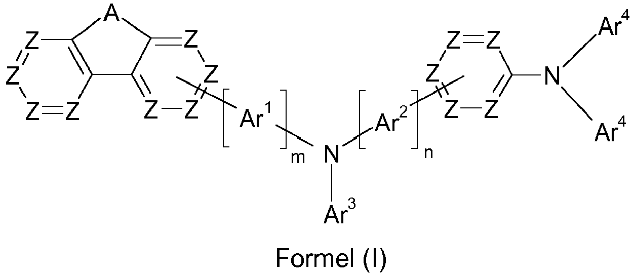


- A
- ist gleich C(R1)2 oder gleich

- Z
- ist bei jedem Auftreten gleich oder verschieden CR1 oder N oder, wenn eine Gruppe in der betreffenden Position gebunden ist, gleich C;
- Ar1,Ar3
- ist bei jedem Auftreten gleich oder verschieden ein aromatisches oder heteroaromatisches Ringsystem mit 5 bis 30 aromatischen Ringatomen, welches mit einem oder mehreren Resten R1 substituiert sein kann;
- Ar2
- ist bei jedem Auftreten gleich oder verschieden eine Arylengruppe mit 6 bis 30 aromatischen Ringatomen oder eine Heteroarylengruppe mit 5 bis 14 aromatischen Ringatomen, welche mit einem oder mehreren Resten R1 substituiert sein kann;
- Ar4
- ist bei jedem Auftreten gleich oder verschieden eine Arylgruppe mit 6 bis 30 aromatischen Ringatomen oder eine Heteroarylgruppe mit 5 bis 14 aromatischen Ringatomen, welche mit einem oder mehreren Resten R1 substituiert sein kann, wobei Reste R1 an Gruppen Ar4 keine Ringe bilden dürfen;
- X
- ist ausgewählt aus einer Einfachbindung, C(R1)2, C=O, Si(R1)2, NR1, O, S, S=O und S(=O)2;
- R1
- ist bei jedem Auftreten gleich oder verschieden H, D, F, Cl, Br, I, B(OR2)2, CHO, C(=O)R2, CR2=C(R2)2, CN, C(=O)OR2, C(=O)N(R2)2, Si(R2)3, N(R2)2, NO2, P(=O)(R2)2, OSO2R2, OR2, S(=O)R2, S(=O)2R2, eine geradkettige Alkyl-, Alkoxy- oder Thio-alkylgruppe mit 1 bis 20 C-Atomen oder eine verzweigte oder cyclische Alkyl-, Alkoxy- oder Thioalkylgruppe mit 3 bis 20 C-Atomen oder eine Alkenyl- oder Alkinylgruppe mit 2 bis 20 C-Atomen, wobei die oben genannten Gruppen jeweils mit einem oder mehreren Resten R2 substituiert sein können und wobei eine oder mehrere CH2-Gruppen in den oben genannten Gruppen durch -R2C=CR2-, -C≡C-, Si(R2)2, C=O, C=S, C=NR2, -C(=O)O-, -C(=O)NR2-, NR2, P(=O)(R2), -O-, -S-, SO oder SO2 ersetzt sein können und wobei ein oder mehrere H-Atome in den oben genannten Gruppen durch D, F, Cl, Br, I, CN oder NO2 ersetzt sein können, oder ein aromatisches oder heteroaromatisches Ringsystem mit 5 bis 30 aromatischen Ringatomen, das jeweils durch einen oder mehrere Reste R2 substituiert sein kann, oder eine Aryloxy- oder Heteroaryloxygruppe mit 5 bis 30 aromatischen Ringatomen, die durch einen oder mehrere Reste R2 substituiert sein kann, wobei zwei oder mehr Reste R1 miteinander verknüpft sein können und einen Ring bilden können;
- R2
- ist bei jedem Auftreten gleich oder verschieden H, D, F, Cl, Br, I, B(OR3)2, CHO, C(=O)R3, CR3=C(R3)2, CN, C(=O)OR3, C(=O)N(R3)2, Si(R3)3, N(R3)2, NO2, P(=O)(R3)2, OSO2R3, OR3, S(=O)R3, S(=O)2R3, eine geradkettige Alkyl-, Alkoxy- oder Thio-alkylgruppe mit 1 bis 20 C-Atomen oder eine verzweigte oder cyclische Alkyl-, Alkoxy- oder Thioalkylgruppe mit 3 bis 20 C-Atomen oder eine Alkenyl- oder Alkinylgruppe mit 2 bis 20 C-Atomen, wobei die oben genannten Gruppen jeweils mit einem oder mehreren Resten R3 substituiert sein können und wobei eine oder mehrere CH2-Gruppen in den oben genannten Gruppen durch -R3C=CR3-, -C≡C-, Si(R3)2, C=O, C=S, C=NR3, -C(=O)O-, -C(=O)NR3-, NR3, P(=O)(R3), -O-, -S-, SO oder SO2 ersetzt sein können und wobei ein oder mehrere H-Atome in den oben genannten Gruppen durch D, F, Cl, Br, I, CN oder NO2 ersetzt sein können, oder ein aromatisches oder heteroaromatisches Ringsystem mit 5 bis 30 aromatischen Ringatomen, das jeweils durch einen oder mehrere Reste R3 substituiert sein kann, oder eine Aryloxy- oder Heteroaryloxygruppe mit 5 bis 30 aromatischen Ringatomen, die durch einen oder mehrere Reste R3 substituiert sein kann, wobei zwei oder mehr Reste R2 miteinander verknüpft sein können und einen Ring bilden können;
- R3
- ist bei jedem Auftreten gleich oder verschieden H, D, F oder ein aliphatischer, aromatischer oder heteroaromatischer organischer Rest mit 1 bis 20 C-Atomen, in dem auch ein oder mehrere H-Atome durch D oder F ersetzt sein können; dabei können zwei oder mehr Substituenten R3 miteinander verknüpft sein und einen Ring bilden;
- m
- ist gleich 0, 1, 2 oder 3, wobei m=0 bedeutet, dass die betreffende Gruppe nicht vorhanden ist;
- n
- ist gleich 0, 1, 2 oder 3, wobei n=0 bedeutet, dass die betreffende Gruppe nicht vorhanden ist;
- Zur Verdeutlichung wird untenstehend die Strukturformel von Fluoren abgebildet, zusammen mit der Nummerierung der Positionen. Bei Spirobifluorenderivaten ist die Nummerierung analog, mit dem einzigen Unterschied, dass die Position 9 nicht substituiert sein kann.

- Weiterhin soll hervorgehoben werden, dass für den Fall m=0 bzw. n=0 die betreffende Gruppe Ar1 bzw. Ar2 nicht vorhanden ist und die beiden an diese Gruppe bindenden Molekülteile direkt miteinander verbunden sind.
- Ist der Index m bzw. n größer als 1, so bedeutet dies, dass mehrere Gruppen Ar1 bzw. Ar2, genauer gesagt m bzw. n Gruppen Ar1 bzw. Ar2 sequentiell hintereinander gebunden sind, so dass beispielsweise für m=2 und Ar1 = Phenylen eine Biphenylengruppe entsteht, die die Fluorenylgruppe und die Gruppe N(Ar3) verbindet. Für m=3 und Ar1 = Phenylen entsteht beispielsweise eine Terphenylengruppe mit hintereinander in Reihe gebundenen Phenylengruppen.
- Weiterhin soll angemerkt werden, dass in den Formeln (II) und (III) die Bindung der Gruppe X an die Gruppe Ar4 an einer beliebigen Position der Gruppe Ar4 erfolgen kann, bevorzugt an einer direkt benachbarten oder an einer nicht mehr als eine Position von einer direkt benachbarten Position entfernten Position, z. B. einer meta-Position, betrachtet von der Bindung der Gruppe Ar4 an das Stickstoffatom. Besonders bevorzugt ist die Gruppe X in einer direkt benachbarten Position, betrachtet von der Bindung der Gruppe Ar4 an das Stickstoffatom, an die Gruppe Ar4 gebunden.
- Eine Arylgruppe im Sinne dieser Erfindung enthält 6 bis 60 aromatische Ringatome; eine Heteroarylgruppe im Sinne dieser Erfindung enthält prinzipiell 5 bis 60 aromatische Ringatome, von denen mindestens eines ein Heteroatom darstellt. Die Heteroatome sind bevorzugt ausgewählt aus N, O und S. Dies stellt die grundlegende Definition dar. Werden in der Beschreibung der vorliegenden Erfindung andere Bevorzugungen angegeben, beispielsweise bezüglich der Zahl der aromatischen Ringatome oder der enthaltenden Heteroatome, so gelten diese.
- Dabei wird unter einer Arylgruppe bzw. Heteroarylgruppe entweder ein einfacher aromatischer Cyclus, also Benzol, bzw. ein einfacher heteroaromatischer Cyclus, beispielsweise Pyridin, Pyrimidin oder Thiophen, oder ein kondensierter (annellierter) aromatischer bzw. heteroaromatischer Polycyclus, beispielsweise Naphthalin, Phenanthren, Chinolin oder Carbazol verstanden. Ein kondensierter (annellierter) aromatischer bzw. heteroaromatischer Polycyclus besteht im Sinne der vorliegenden Anmeldung aus zwei oder mehr miteinander kondensierten einfachen aromatischen bzw. heteroaromatischen Cyclen.
- Unter einer Aryl- oder Heteroarylgruppe, die jeweils mit den oben genannten Resten substituiert sein kann und die über beliebige Positionen am Aromaten bzw. Heteroaromaten verknüpft sein kann, werden insbesondere Gruppen verstanden, welche abgeleitet sind von Benzol, Naphthalin, Anthracen, Phenanthren, Pyren, Dihydropyren, Chrysen, Perylen, Fluoranthen, Benzanthracen, Benzphenanthren, Tetracen, Pentacen, Benzpyren, Furan, Benzofuran, Isobenzofuran, Dibenzofuran, Thiophen, Benzothiophen, Isobenzothiophen, Dibenzothiophen, Pyrrol, Indol, Isoindol, Carbazol, Pyridin, Chinolin, Isochinolin, Acridin, Phenanthridin, Benzo-5,6-chinolin, Benzo-6,7-chinolin, Benzo-7,8-chinolin, Phenothiazin, Phenoxazin, Pyrazol, Indazol, Imidazol, Benzimidazol, Naphthimidazol, Phenanthrimidazol, Pyridimidazol, Pyrazinimidazol, Chinoxalinimidazol, Oxazol, Benzoxazol, Naphthoxazol, Anthroxazol, Phenanthroxazol, Isoxazol, 1,2-Thiazol, 1,3-Thiazol, Benzothiazol, Pyridazin, Benzopyridazin, Pyrimidin, Benzpyrimidin, Chinoxalin, Pyrazin, Phenazin, Naphthyridin, Azacarbazol, Benzocarbolin, Phenanthrolin, 1,2,3-Triazol, 1,2,4-Triazol, Benzotriazol, 1,2,3-Oxadiazol, 1,2,4-Oxadiazol, 1,2,5-Oxadiazol, 1,3,4-Oxadiazol, 1,2,3-Thiadiazol, 1,2,4-Thiadiazol, 1,2,5-Thiadiazol, 1,3,4-Thiadiazol, 1,3,5-Triazin, 1,2,4-Triazin, 1,2,3-Triazin, Tetrazol, 1,2,4,5-Tetrazin, 1,2,3,4-Tetrazin, 1,2,3,5-Tetrazin, Purin, Pteridin, Indolizin und Benzothiadiazol.
- Unter einer Aryloxygruppe gemäß der Definition der vorliegenden Erfindung wird eine Arylgruppe, wie oben definiert, verstanden, welche über ein Sauerstoffatom gebunden ist. Eine analoge Definition gilt für Heteroaryloxygruppen.
- Eine Aralkylgruppe im Sinne dieser Erfindung ist eine mit einer Arylgruppe substituierte Alkylgruppe, wobei der Begriff Arylgruppe wie oben definiert zu verstehen ist und die Alkylgruppe 1 bis 20 C-Atome aufweist, wobei in der Alkylgruppe auch einzelne H-Atome und/oder CH2-Gruppen durch die bei der Definition der Alkylgruppen genannten Gruppen ersetzt sein können und wobei die Alkylgruppe diejenige Gruppe darstellt, welche an den Rest der Verbindung bindet. Entsprechend stellt eine Heteroaralkylgruppe eine mit einer Heteroarylgruppe substituierte Alkylgruppe dar, wobei der Begriff Heteroarylgruppe wie oben definiert zu verstehen ist und die Alkylgruppe 1 bis 20 C-Atome aufweist, wobei in der Alkylgruppe auch einzelne H-Atome und/oder CH2-Gruppen durch die bei der Definition der Alkylgruppen genannten Gruppen ersetzt sein können und wobei die Alkylgruppe diejenige Gruppe darstellt, welche an den Rest der Verbindung bindet.
- Ein aromatisches Ringsystem im Sinne dieser Erfindung enthält 6 bis 60 C-Atome im Ringsystem. Ein heteroaromatisches Ringsystem im Sinne dieser Erfindung enthält 5 bis 60 aromatische Ringatome, von denen mindestens eines ein Heteroatom darstellt. Die Heteroatome sind bevorzugt ausgewählt aus N, O und/oder S. Unter einem aromatischen oder heteroaromatischen Ringsystem im Sinne dieser Erfindung soll ein System verstanden werden, das nicht notwendigerweise nur Aryl- oder Heteroarylgruppen enthält, sondern in dem auch mehrere Aryl- oder Heteroarylgruppen durch eine nicht-aromatische Einheit (bevorzugt weniger als 10 % der von H verschiedenen Atome), wie z. B. ein sp3-hybridisiertes C-, Si-, N- oder O-Atom, ein sp2-hybridisiertes C- oder N-Atom oder ein sp-hybridisiertes C-Atom, verbunden sein können. So sollen beispielsweise auch Systeme wie 9,9'-Spirobifluoren, 9,9'-Diarylfluoren, Triarylamin, Diarylether, Stilben, etc. als aromatische Ringsysteme im Sinne dieser Erfindung verstanden werden, und ebenso Systeme, in denen zwei oder mehrere Arylgruppen beispielsweise durch eine lineare oder cyclische Alkyl-, Alkenyl- oder Alkinylgruppe oder durch eine Silylgruppe verbunden sind. Weiterhin werden auch Systeme, in denen zwei oder mehr Aryl- oder Heteroarylgruppen über Einfachbindungen miteinander verknüpft sind, als aromatische oder heteroaromatische Ringsysteme im Sinne dieser Erfindung verstanden, wie beispielsweise Systeme wie Biphenyl, Terphenyl oder Diphenyltriazin.
- Unter einem aromatischen oder heteroaromatischen Ringsystem mit 5 - 60 aromatischen Ringatomen, welches noch jeweils mit Resten wie oben definiert substituiert sein kann und welches über beliebige Positionen am Aromaten bzw. Heteroaromaten verknüpft sein kann, werden insbesondere Gruppen verstanden, die abgeleitet sind von Benzol, Naphthalin, Anthracen, Benzanthracen, Phenanthren, Benzphenanthren, Pyren, Chrysen, Perylen, Fluoranthen, Naphthacen, Pentacen, Benzpyren, Biphenyl, Biphenylen, Terphenyl, Terphenylen, Quaterphenyl, Fluoren, Spirobifluoren, Dihydrophenanthren, Dihydropyren, Tetrahydropyren, cis- oder trans-Indenofluoren, Truxen, Isotruxen, Spirotruxen, Spiroisotruxen, Furan, Benzofuran, Isobenzofuran, Dibenzofuran, Thiophen, Benzothiophen, Isobenzothiophen, Dibenzothiophen, Pyrrol, Indol, Isoindol, Carbazol, Indolocarbazol, Indenocarbazol, Pyridin, Chinolin, Isochinolin, Acridin, Phenanthridin, Benzo-5,6-chinolin, Benzo-6,7-chinolin, Benzo-7,8-chinolin, Phenothiazin, Phenoxazin, Pyrazol, Indazol, Imidazol, Benzimidazol, Naphthimidazol, Phenanthrimidazol, Pyridimidazol, Pyrazinimidazol, Chinoxalinimidazol, Oxazol, Benzoxazol, Naphthoxazol, Anthroxazol, Phenanthroxazol, Isoxazol, 1,2-Thiazol, 1,3-Thiazol, Benzothiazol, Pyridazin, Benzopyridazin, Pyrimidin, Benzpyrimidin, Chinoxalin, 1,5-Diazaanthracen, 2,7-Diazapyren, 2,3-Diazapyren, 1,6-Diazapyren, 1,8-Diazapyren, 4,5-Diazapyren, 4,5,9,10-Tetraazaperylen, Pyrazin, Phenazin, Phenoxazin, Phenothiazin, Fluorubin, Naphthyridin, Azacarbazol, Benzocarbolin, Phenanthrolin, 1,2,3-Triazol, 1,2,4-Triazol, Benzotriazol, 1,2,3-Oxadiazol, 1,2,4-Oxadiazol, 1,2,5-Oxadiazol, 1,3,4-Oxadiazol, 1,2,3-Thiadiazol, 1,2,4-Thiadiazol, 1,2,5-Thiadiazol, 1,3,4-Thiadiazol, 1,3,5-Triazin, 1,2,4-Triazin, 1,2,3-Triazin, Tetrazol, 1,2,4,5-Tetrazin, 1,2,3,4-Tetrazin, 1,2,3,5-Tetrazin, Purin, Pteridin, Indolizin und Benzothiadiazol oder Kombinationen dieser Gruppen.
- Im Rahmen der vorliegenden Erfindung werden unter einer geradkettigen Alkylgruppe mit 1 bis 40 C-Atomen bzw. einer verzweigten oder cyclischen Alkylgruppe mit 3 bis 40 C-Atomen bzw. einer Alkenyl- oder Alkinylgruppe mit 2 bis 40 C-Atomen, in der auch einzelne H-Atome oder CH2-Gruppen durch die oben bei der Definition der Reste genannten Gruppen substituiert sein können, bevorzugt die Reste Methyl, Ethyl, n-Propyl, i-Propyl, n-Butyl, i-Butyl, s-Butyl, t-Butyl, 2-Methylbutyl, n-Pentyl, s-Pentyl, Cyclopentyl, neo-Pentyl, n-Hexyl, Cyclohexyl, neo-Hexyl, n-Heptyl, Cycloheptyl, n-Octyl, Cyclooctyl, 2-Ethylhexyl, Trifluormethyl, Pentafluorethyl, 2,2,2-Trifluorethyl, Ethenyl, Propenyl, Butenyl, Pentenyl, Cyclopentenyl, Hexenyl, Cyclohexenyl, Heptenyl, Cycloheptenyl, Octenyl, Cyclooctenyl, Ethinyl, Propinyl, Butinyl, Pentinyl, Hexinyl oder Octinyl verstanden. Unter einer Alkoxy- oder Thioalkylgruppe mit 1 bis 40 C-Atomen werden bevorzugt Methoxy, Trifluormethoxy, Ethoxy, n-Propoxy, i-Propoxy, n-Butoxy, i-Butoxy, s-Butoxy, t-Butoxy, n-Pentoxy, s-Pentoxy, 2-Methylbutoxy, n-Hexoxy, Cyclohexyloxy, n-Heptoxy, Cycloheptyloxy, n-Octyloxy, Cyclooctyloxy, 2-Ethylhexyloxy, Pentafluorethoxy, 2,2,2-Trifluorethoxy, Methylthio, Ethylthio, n-Propylthio, i-Propylthio, n-Butylthio, i-Butylthio, s-Butylthio, t-Butylthio, n-Pentylthio, s-Pentylthio, n-Hexylthio, Cyclohexylthio, n-Heptylthio, Cycloheptylthio, n-Octylthio, Cyclooctylthio, 2-Ethylhexylthio, Trifluormethylthio, Pentafluorethylthio, 2,2,2-Trifluorethylthio, Ethenylthio, Propenylthio, Butenylthio, Pentenylthio, Cyclopentenylthio, Hexenylthio, Cyclohexenylthio, Heptenylthio, Cycloheptenylthio, Octenylthio, Cyclooctenylthio, Ethinylthio, Propinylthio, Butinylthio, Pentinylthio, Hexinylthio, Heptinylthio oder Octinylthio verstanden.
- Unter der Formulierung, dass zwei oder mehr Reste miteinander einen Ring bilden können, soll im Rahmen der vorliegenden Beschreibung unter anderem verstanden werden, dass die beiden Reste miteinander durch eine chemische Bindung verknüpft sind. Dies wird durch das folgende Schema verdeutlicht:

- Weiterhin soll unter der oben genannten Formulierung aber auch verstanden werden, dass für den Fall, dass einer der beiden Reste Wasserstoff darstellt, der zweite Rest unter Bildung eines Rings an die Position, an die das Wasserstoffatom gebunden war, bindet. Dies soll durch das folgende Schema verdeutlicht werden:

- Eine Verbindung der Formel (I) kann erfindungsgemäß eine Verbindung der folgenden Formeln (I-A) bis (I-C) darstellen:


- Eine Verbindung der Formel (II) kann erfindungsgemäß eine Verbindung der folgenden Formeln (II-A) bis (II-C) darstellen:
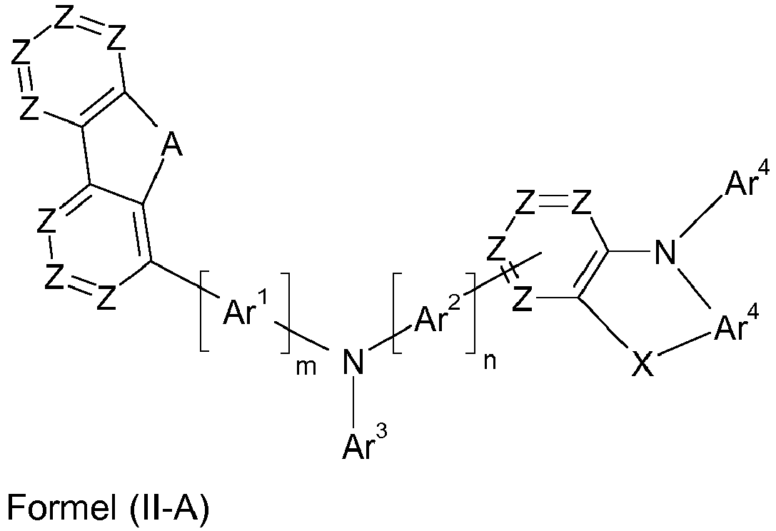


- Eine Verbindung der Formel (III) kann erfindungsgemäß eine Verbindung der folgenden Formeln (III-A) bis (III-C) darstellen:


- Bevorzugt sind Verbindungen der Formeln (I-B), (II-B) und (III-B).
- Es gelten gemäß der vorliegenden Erfindung die folgenden Bevorzugungen für Verbindungen der Formel (I), (II) oder (III).
- Bevorzugt ist die Gruppe Ar1 oder, für den Fall dass m=0 gilt, die Gruppe N(Ar3), in 3-Position am Fluorenyl-Ringsystem gebunden.
- Es ist erfindungsgemäß bevorzugt, dass nicht mehr als zwei Z pro aromatischem Ring in Formel (I), (II) bzw. (III) gleich N sind, besonders bevorzugt nicht mehr als ein Z.
- Weiterhin ist es bevorzugt, dass Z in der Fluorenylgruppe gleich CR1 ist.
- Weiterhin ist es allgemein bevorzugt, dass Z gleich CR1 ist, wenn keine Gruppe in der betreffenden Position gebunden ist, und dass Z gleich C ist, wenn eine Gruppe in der betreffenden Position gebunden ist.
- Weiterhin ist A bevorzugt gleich C(R1)2.
- Bevorzugt ist für Formel (II) für den Fall, dass X eine Einfachbindung darstellt, Z gleich CR1 oder, wenn eine Gruppe in der betreffenden Position gebunden ist, gleich C. Besonders bevorzugt ist für Formel (II) die Gruppe Z gleich CR1 oder, wenn eine Gruppe in der betreffenden Position gebunden ist, gleich C.
- Weiterhin bevorzugt bilden Reste R1, welche Bestandteil einer Gruppe Z sind, für Verbindungen der Formel (II) keine Ringe miteinander. Besonders bevorzugt bilden Reste R1, welche Bestandteile einer Gruppe Z sind, für Verbindungen der Formel (II) für den Fall, dass X eine Einfachbindung darstellt, keine Ringe miteinander.
- Für Ar1 gilt, dass dieses bevorzugt ein aromatisches oder heteroaromatisches Ringsystem mit 5 bis 24 aromatischen Ringatomen darstellt. Besonders bevorzugt ist Ar1 ein aromatisches Ringsystem mit 6 bis 18 aromatischen Ringatomen, ganz besonders bevorzugt 6 bis 12 aromatischen Ringatomen. Am stärksten bevorzugt ist Ar1 eine Arylengruppe mit 6 bis 10 aromatischen Ringatomen. Es gilt allgemein, dass die angegebenen Gruppen mit einem oder mehreren Resten R1 substituiert sein können.
- Für Ar2 gilt, dass dieses bevorzugt eine Arylengruppe mit 6 bis 10 aromatischen Ringatomen oder eine Heteroarylengruppe mit 5 bis 14 aromatischen Ringatomen darstellt. Besonders bevorzugt ist Ar2 eine Phenylengruppe. Es gilt allgemein, dass die angegebenen Gruppen mit einem oder mehreren Resten R1 substituiert sein können. Es ist erfindungsgemäß bevorzugt, dass Reste R1 an Gruppen Ar2 keine Ringe miteinander bilden.
- Für Ar3 gilt, dass dieses bevorzugt ein aromatisches oder heteroaromatisches Ringsystem mit 5 bis 24 aromatischen Ringatomen darstellt. Besonders bevorzugt ist Ar3 ein aromatisches Ringsystem mit 6 bis 18 aromatischen Ringatomen. Es gilt allgemein, dass die angegebenen Gruppen mit einem oder mehreren Resten R1 substituiert sein können.
- Ar4 ist bevorzugt eine Arylgruppe mit 6 bis 10 aromatischen Ringatomen oder eine Heteroarylgruppe mit 5 bis 14 aromatischen Ringatomen. Besonders bevorzugt ist Ar4 eine Phenylgruppe. Es gilt allgemein, dass die angegebenen Gruppen mit einem oder mehreren Resten R1 substituiert sein können.
- Die Gruppe X ist bevorzugt ausgewählt aus einer Einfachbindung, C(R1)2, O oder S. Ganz besonders bevorzugt ist X eine Einfachbindung.
- Bevorzugt ist der Rest R1 bei jedem Auftreten gleich oder verschieden ausgewählt aus H, D, F, CN, Si(R2)3, N(R2)2 oder einer geradkettigen Alkyl- oder Alkoxygruppe mit 1 bis 20 C-Atomen oder einer verzweigten oder cyclischen Alkyl- oder Alkoxygruppe mit 3 bis 20 C-Atomen, wobei die oben genannten Gruppen jeweils mit einem oder mehreren Resten R2 substituiert sein können und wobei in den oben genannten Gruppen eine oder mehrere CH2-Gruppen durch -C≡C-, -R2C=CR2-, Si(R2)2, C=O, C=NR2, -NR2-, -O-, -S-, -C(=O)O- oder -C(=O)NR2- ersetzt sein können, oder ein aromatisches oder heteroaromatisches Ringsystem mit 5 bis 20 aromatischen Ringatomen, das jeweils mit einem oder mehreren Resten R2 substituiert sein kann, wobei zwei oder mehr Reste R1 miteinander verknüpft sein können und einen Ring bilden können.
- Bevorzugt ist der Rest R2 bei jedem Auftreten gleich oder verschieden ausgewählt aus H, D, F, CN, Si(R3)3, N(R3)2 oder einer geradkettigen Alkyl- oder Alkoxygruppe mit 1 bis 20 C-Atomen oder einer verzweigten oder cyclischen Alkyl- oder Alkoxygruppe mit 3 bis 20 C-Atomen, wobei die oben genannten Gruppen jeweils mit einem oder mehreren Resten R3 substituiert sein können und wobei in den oben genannten Gruppen eine oder mehrere CH2-Gruppen durch -C≡C-, -R3C=CR3-, Si(R3)2, C=O, C=NR3, -NR3-, -O-, -S-, -C(=O)O- oder -C(=O)NR3- ersetzt sein können, oder ein aromatisches oder heteroaromatisches Ringsystem mit 5 bis 20 aromatischen Ringatomen, das jeweils mit einem oder mehreren Resten R3 substituiert sein kann, wobei zwei oder mehr Reste R2 miteinander verknüpft sein können und einen Ring bilden können.
- Weiterhin ist es bevorzugt, dass m gleich 0 oder 1 ist. Besonders bevorzugt ist m gleich 0.
- Für Formel (II) und (III) ist es allgemein bevorzugt, dass n gleich 1, 2 oder 3 ist. Für Formel (II) ist es besonders bevorzugt, dass n gleich 1 ist.
- Weiterhin ist es allgemein für die Formeln (I), (II) und (III) bevorzugt, dass n gleich 1, 2 oder 3 ist, besonders bevorzugt gleich 1 oder 2, ganz besonders bevorzugt gleich 1.
- Es ist für die erfindungsgemäßen Verbindungen allgemein bevorzugt, dass keine Heteroarylgruppe mit mehr als 10 aromatischen Ringatomen vorhanden ist. Besonders bevorzugt ist keine Heteroarylgruppe mit mehr als 6 aromatischen Ringatomen vorhanden. Ganz besonders bevorzugt enthalten die erfindungsgemäßen Verbindungen keine Heteroarylgruppe gleich welcher Größe.
- Weiterhin ist es für die erfindungsgemäßen Verbindungen bevorzugt, dass keine kondensierte Arylgruppe mit mehr als 14 aromatischen Ringatomen in der Verbindung vorhanden ist. Besonders bevorzugt ist keine kondensierte Arylgruppe mit mehr als 10 aromatischen Ringatomen vorhanden.
- Weiterhin ist es bevorzugt, dass in Verbindungen der Formel (I) die Gruppe Ar2 bzw. die Gruppe N(Ar3) in para-Position zum Stickstoffatom an den unten gezeigten Teil der Verbindung gebunden ist

- Weiterhin ist es bevorzugt, dass in Verbindungen der Formel (II) die Gruppe Ar2 bzw. die Gruppe N(Ar3) in para-Position zum Stickstoffatom an den unten gezeigten Teil der Verbindung gebunden ist
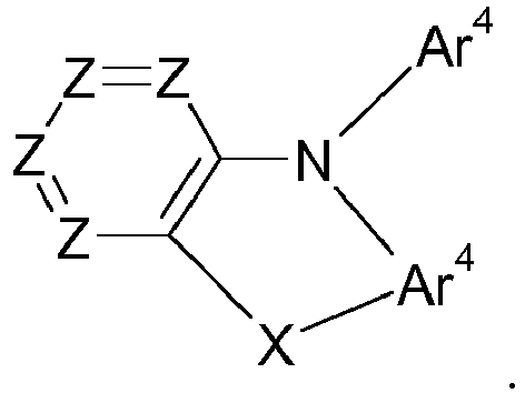
- Weiterhin ist es bevorzugt, dass in Verbindungen der Formel (III) die Gruppe Ar2 bzw. die Gruppe N(Ar3) in para-Position zum Stickstoffatom an den unten gezeigten Teil der Verbindung gebunden ist
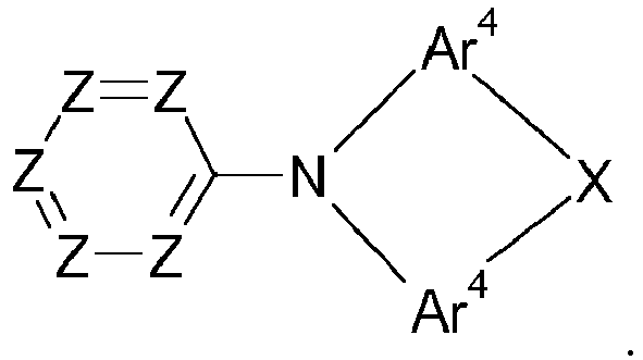
- Weiterhin bevorzugt ist die Verbindung der Formel (I), (II) oder (II) asymmetrisch. Weiterhin bevorzugt kann die Verbindung nicht in einer spiegelsymmetrischen Strukturformel dargestellt werden.
- Weiterhin ist es bevorzugt, dass die Verbindung der Formel (I), (II) oder (III) zusätzlich zu den beiden abgebildeten Triarylaminogruppen keine weitere Triarylaminogruppe aufweist. Es ist ebenfalls bevorzugt, dass die Verbindung kein weiteres Carbazolderivat enthält außer solchen, welche sich in Formel (II) oder (III) für X als Einfachbindung ergeben.
- Bevorzugte Ausführungsformen von Formel (I) entsprechen den folgenden Formeln (I-1) bis (I-48)


- Bevorzugte Ausführungsformen von Formel (II) entsprechen den folgenden Formeln (II-1) bis (II-24)


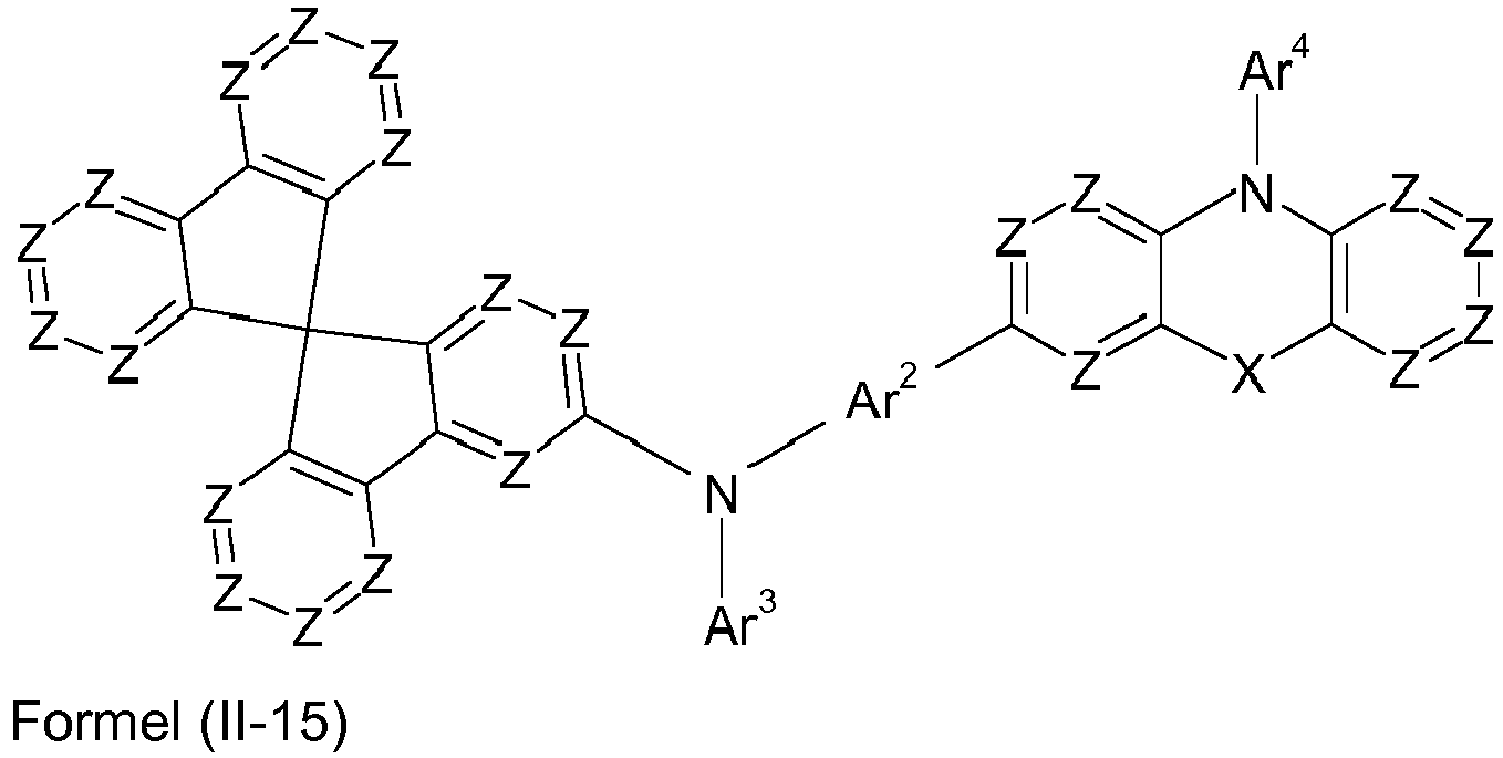

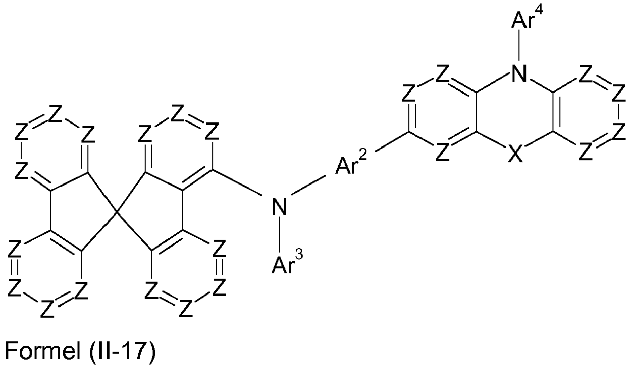


- Bevorzugte Ausführungsformen von Verbindungen gemäß Formel (III) entsprechen den folgenden Formeln (III-1) bis (III-48)


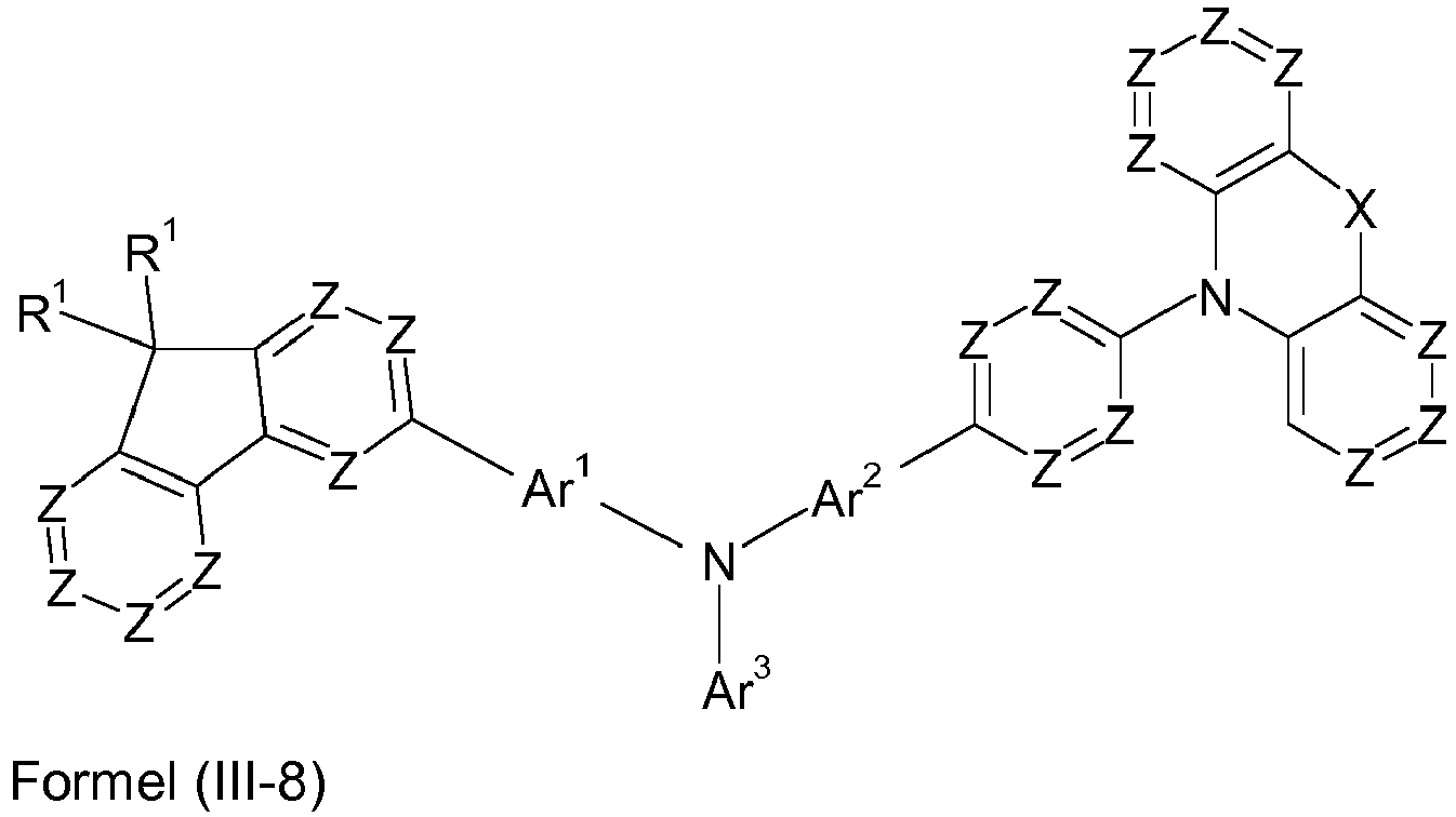
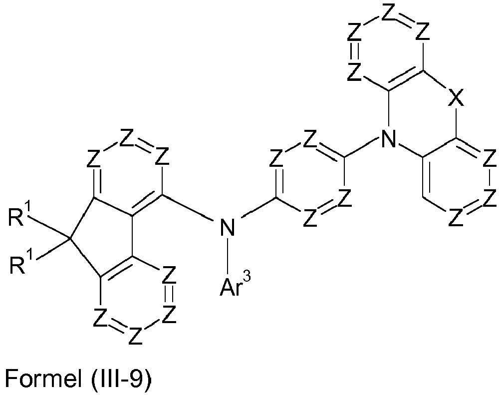


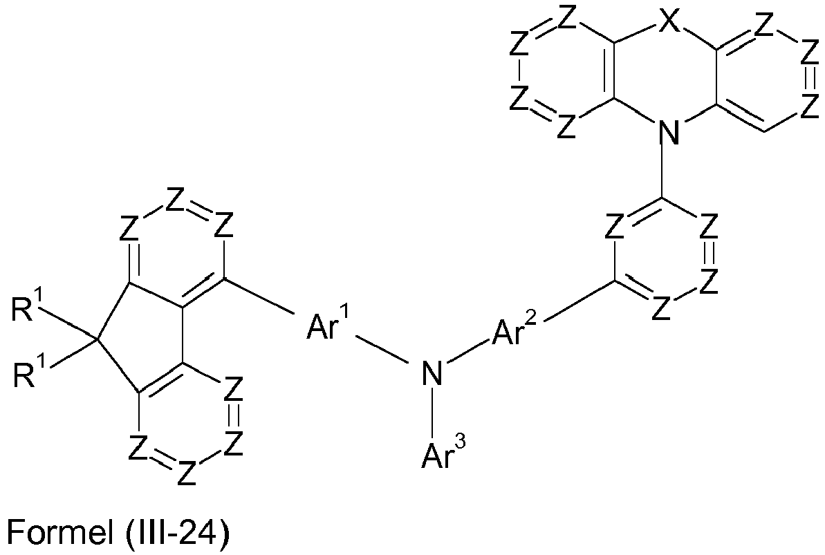


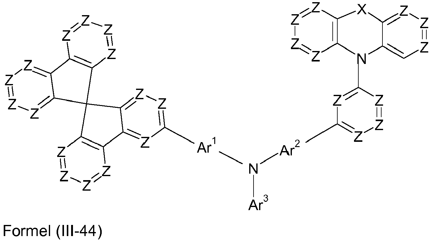


- Explizite Beispiele für erfindungsgemäße Verbindungen sind in der folgenden Tabelle aufgeführt.


1 2 3 

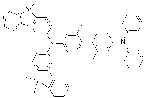
4 5 6 

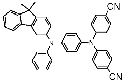
7 8 9 


10 11 12 


13 14 15 
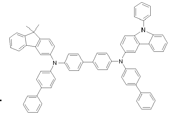

16 17 18 


19 20 21 

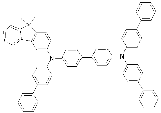
22 23 24 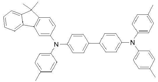


25 26 27 


28 29 30 


31 32 33 
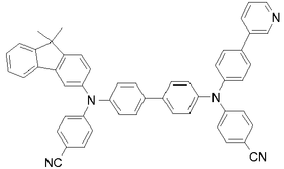

34 35 36 


37 38 39 


40 41 42 


43 44 45 


46 47 48 

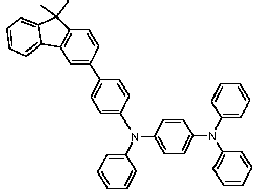
49 50 51 


52 53 54 


55 56 57 


58 59 60 


61 62 63 


64 65 66 


67 68 69 


70 71 72 


73 74 75 


76 77 78 


79 80 81 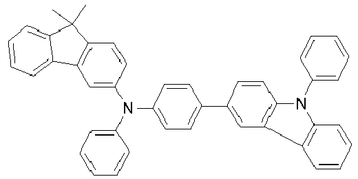


82 83 84 


85 86 87 


88 89 90 


91 92 93 


94 95 96 


97 98 99 


100 101 102 


103 104 105 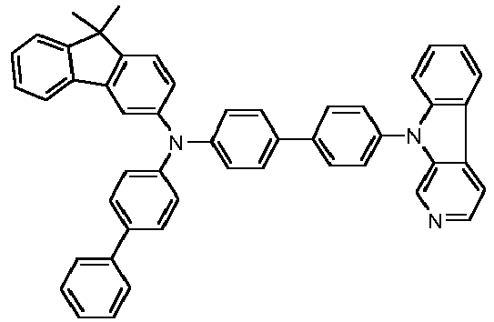


106 107 108 


109 110 111 
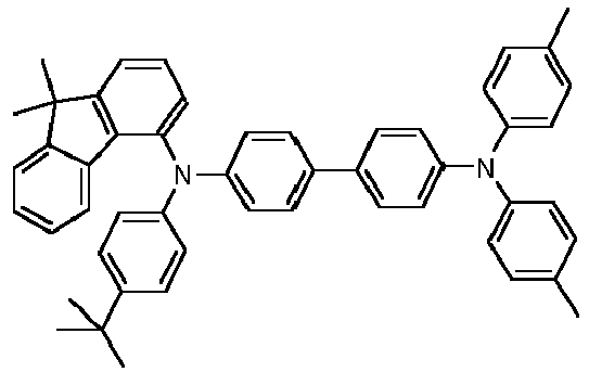

112 113 114 


115 116 117 


118 119 120 


121 122 123 


124 125 126 


127 128 129 


130 131 132 
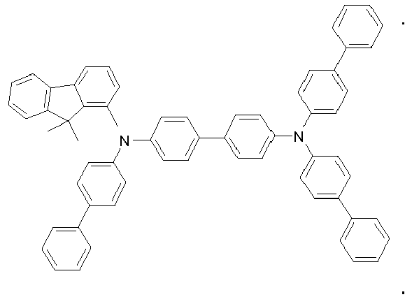

133 134 135 


136 137 138 
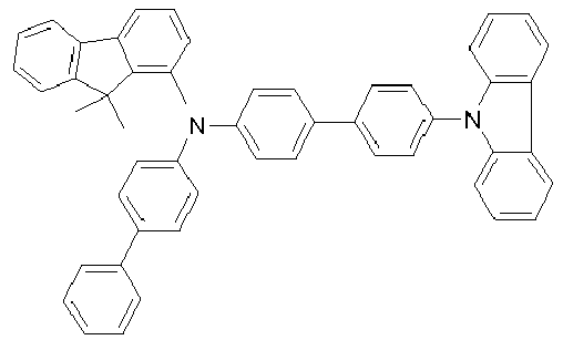

139 140 141 


142 143 144 


145 146 147 


148 149 150 


151 152 153 

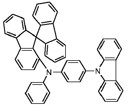
154 155 156 

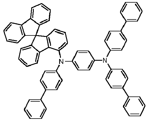
157 158 159 


160 161 162 
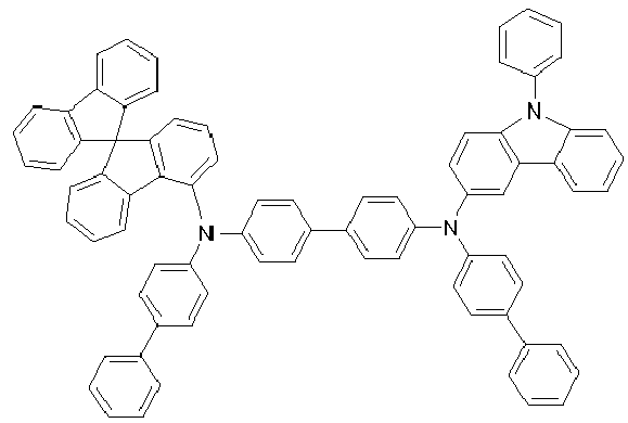

163 164 165 


166 167 168 


169 170 171 


172 173 174 
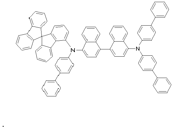

175 176 177 


178 179 180 


181 182 183 


184 185 186 


187 188 189 


190 191 192 


193 194 195 
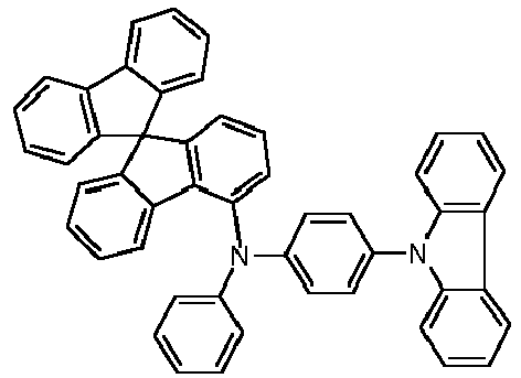

196 197 198 


199 200 201 


202 203 204 


205 206 207 


208 209 210 


211 212 213 
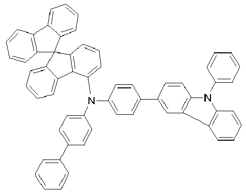

214 215 216 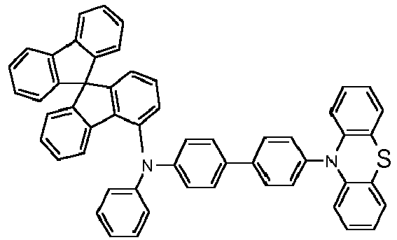

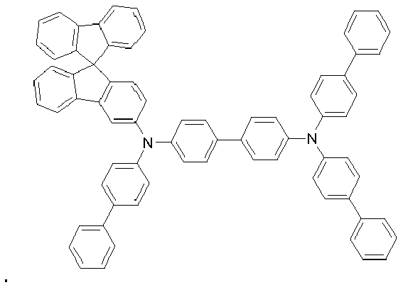
217 218 219 
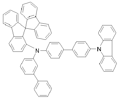

220 221 222 


223 224 225 


226 227 228 


229 230 231 


232 233 234 


235 236 237 

238 239 - Die Synthese der erfindungsgemäßen Verbindungen kann gemäß im Stand der Technik bekannten Verfahren und Reaktionstypen, beispielsweise Halogenierung, Buchwald-Kupplung und Suzuki-Kupplung erfolgen.
- Ein bevorzugter Syntheseweg zur Herstellung der erfindungsgemäßen Verbindungen wird im Folgenden dargestellt. Der Syntheseweg umfasst zwei Kupplungsreaktionen: zunächst wird das Fluoren- bzw. Spirobifluorenderivat in einer ersten Buchwald-Kupplung mit einem Amin der Formel Ar3-NH2 (vgl. Formeln (I) bis (III) der erfindungsgemäßen Verbindungen) umgesetzt. Schließlich erfolgt eine zweite Buchwald-Kupplung, um den Molekülteil enthaltend die zweite Arylamino- bzw. Carbazolgruppe einzuführen.
- Der Syntheseweg wird im Folgenden beispielhaft anhand einer Verbindung der Formel (I) dargestellt (Schema 1). Es soll jedoch betont werden, dass auf diesem Syntheseweg gleichermaßen auch erfindungsgemäße Verbindungen der Formel (II) oder (III) hergestellt werden können. Analog zu den dargestellten Fluorenyl-Ausgangsverbindungen können auch Spirobifluorenyl-Verbindungen eingesetzt werden, so dass erfindungsgemäße Verbindungen enthaltend Spirobifluoren-Einheiten erhalten werden.

- Synthesewege für die Ausgangsverbindungen A, B und C, welche in der Synthese der erfindungsgemäßen Verbindungen eingesetzt werden (vgl. Schema 1), sind dem Fachmann bekannt. Weiterhin werden in den Ausführungsbeispielen einige explizite Syntheseverfahren im Detail dargestellt.
- Gegenstand der vorliegenden Erfindung ist somit ein Verfahren zur Herstellung einer Verbindung gemäß Formel (I), (II) oder (III), dadurch gekennzeichnet, dass ein Fluorenyl- oder Spirobifluorenyl-Derivat in einer ersten Kupplungsreaktion mit einer Arylaminoverbindung umgesetzt wird, und das erhaltene Produkt in einer zweiten Kupplungsreaktion mit einer Triarylamino- oder Carbazolverbindung umgesetzt wird.
- Die Kupplungsreaktionen stellen dabei bevorzugt Buchwald-Kupplungen dar.
- Die oben beschriebenen erfindungsgemäßen Verbindungen, insbesondere Verbindungen, welche mit reaktiven Abgangsgruppen, wie Brom, Iod, Chlor, Boronsäure oder Boronsäureester, substituiert sind, können als Monomere zur Erzeugung entsprechender Oligomere, Dendrimere oder Polymere Verwendung finden. Die Oligomerisation bzw. Polymerisation erfolgt dabei bevorzugt über die Halogenfunktionalität bzw. die Boronsäurefunktionalität.
- Weiterer Gegenstand der Erfindung sind daher Oligomere, Polymere oder Dendrimere enthaltend eine oder mehrere Verbindungen gemäß Formel (I), (II) oder (III), wobei die Bindung(en) zum Polymer, Oligomer oder Dendrimer an beliebigen, in Formel (I), (II) bzw. (III) mit R1 substituierten Positionen lokalisiert sein können. Je nach Verknüpfung der erfindungsgemäßen Verbindung ist die Verbindung Bestandteil einer Seitenkette des Oligomers oder Polymers oder Bestandteil der Hauptkette. Unter einem Oligomer im Sinne dieser Erfindung wird eine Verbindung verstanden, welche aus mindestens drei Monomereinheiten aufgebaut ist. Unter einem Polymer im Sinne der Erfindung wird eine Verbindung verstanden, die aus mindestens zehn Monomereinheiten aufgebaut ist. Die erfindungsgemäßen Polymere, Oligomere oder Dendrimere können konjugiert, teilkonjugiert oder nicht-konjugiert sein. Die erfindungsgemäßen Oligomere oder Polymere können linear, verzweigt oder dendritisch sein. In den linear verknüpften Strukturen können die Einheiten gemäß Formel (I), (II) oder (III) direkt miteinander verknüpft sein oder sie können über eine bivalente Gruppe, beispielsweise über eine substituierte oder unsubstituierte Alkylengruppe, über ein Heteroatom oder über eine bivalente aromatische oder heteroaromatische Gruppe miteinander verknüpft sein. In verzweigten und dendritischen Strukturen können beispielsweise drei oder mehrere Einheiten gemäß Formel (I), (II) oder (III) über eine trivalente oder höhervalente Gruppe, beispielsweise über eine trivalente oder höhervalente aromatische oder heteroaromatische Gruppe, zu einem verzweigten bzw. dendritischen Oligomer oder Polymer verknüpft sein.
Für die Wiederholeinheiten gemäß Formel (I), (II) oder (III) in Oligomeren, Dendrimeren und Polymeren gelten dieselben Bevorzugungen wie oben für die erfindungsgemäßen Verbindungen beschrieben. - Zur Herstellung der Oligomere oder Polymere werden die erfindungsgemäßen Monomere homopolymerisiert oder mit weiteren Monomeren copolymerisiert. Geeignete und bevorzugte Comonomere sind gewählt aus Fluorenen (z. B. gemäß
EP 842208 WO 2000/22026 EP 707020 EP 894107 WO 2006/061181 ), Paraphenylenen (z. B. gemäßWO 1992/18552 WO 2004/070772 oderWO 2004/113468 ), Thiophenen (z. B. gemäßEP 1028136 ), Dihydrophenanthrenen (z. B. gemäßWO 2005/014689 oderWO 2007/006383 ), cis- und trans-Indenofluorenen (z. B. gemäßWO 2004/041901 oderWO 2004/113412 ), Ketonen (z. B. gemäßWO 2005/040302 ), Phenanthrenen (z. B. gemäßWO 2005/104264 oderWO 2007/017066 ) oder auch mehreren dieser Einheiten. Die Polymere, Oligomere und Dendrimere enthalten üblicherweise noch weitere Einheiten, beispielsweise emittierende (fluoreszierende oder phosphoreszierende) Einheiten, wie z. B. Vinyltriarylamine (z. B. gemäßWO 2007/068325 ) oder phosphoreszierende Metallkomplexe (z. B. gemäßWO 2006/003000 ), und/oder Ladungstransporteinheiten, insbesondere solche basierend auf Triarylaminen. - Die erfindungsgemäßen Polymere, Oligomere und Dendrimere weisen vorteilhafte Eigenschaften, insbesondere hohe Lebensdauern, hohe Effizienzen und gute Farbkoordinaten auf.
- Die erfindungsgemäßen Polymere und Oligomere werden in der Regel durch Polymerisation von einer oder mehreren Monomersorten hergestellt, von denen mindestens ein Monomer im Polymer zu Wiederholungseinheiten der Formel (I), (II) oder (III) führt. Geeignete Polymerisationsreaktionen sind dem Fachmann bekannt und in der Literatur beschrieben. Besonders geeignete und bevorzugte Polymerisationsreaktionen, die zu C-C- bzw. C-N-Verknüpfungen führen, sind folgende:
- (A) SUZUKI-Polymerisation;
- (B) YAMAMOTO-Polymerisation;
- (C) STILLE-Polymerisation; und
- (D) HARTWIG-BUCHWALD-Polymerisation.
- Wie die Polymerisation nach diesen Methoden durchgeführt werden kann und wie die Polymere dann vom Reaktionsmedium abgetrennt und aufgereinigt werden können, ist dem Fachmann bekannt und in der Literatur, beispielsweise in
WO 2003/048225 ,WO 2004/037887 undWO 2004/037887 , im Detail beschrieben. - Gegenstand der vorliegenden Erfindung ist somit auch ein Verfahren zur Herstellung der erfindungsgemäßen Polymere, Oligomere und Dendrimere, das dadurch gekennzeichnet ist, dass sie durch Polymerisation gemäß SUZUKI, Polymerisation gemäß YAMAMOTO, Polymerisation gemäß STILLE oder Polymerisation gemäß HARTWIG-BUCHWALD hergestellt werden. Die erfindungsgemäßen Dendrimere können gemäß dem Fachmann bekannten Verfahren oder in Analogie dazu hergestellt werden. Geeignete Verfahren sind in der Literatur beschrieben, wie z. B. in Frechet, Jean M. J.; Hawker, Craig J., "Hyperbranched polyphenylene and hyperbranched polyesters: new soluble, three-dimensional, reactive polymers", Reactive & Functional Polymers (1995), 26(1-3), 127-36; Janssen, H. M.; Meijer, E. W., "The synthesis and characterization of dendritic molecules", Materials Science and Technology (1999), 20 (Synthesis of Polymers), 403-458; Tomalia, Donald A., "Dendrimer molecules", Scientific American (1995), 272(5), 62-6;
WO 2002/067343 A1 undWO 2005/026144 A1 . - Für die Verarbeitung der Verbindungen gemäß Formel (I), (II) oder (III) aus flüssiger Phase, beispielsweise durch Spin-Coating oder durch Druckverfahren, sind Formulierungen der Verbindungen erforderlich. Diese Formulierungen können beispielsweise Lösungen, Dispersionen oder Miniemulsionen sein.
- Gegenstand der Erfindung ist daher weiterhin eine Formulierung, insbesondere eine Lösung, Dispersion oder Miniemulsion, enthaltend mindestens eine Verbindung gemäß Formel (I), (II) oder (III) oder mindestens ein Polymer, Oligomer oder Dendrimer enthaltend mindestens eine Einheit gemäß Formel (I), (II) oder (III) sowie mindestens ein Lösungsmittel, bevorzugt ein organisches Lösungsmittel. Wie solche Lösungen hergestellt werden können, ist dem Fachmann bekannt und beispielsweise in den Anmeldungen
WO 2002/072714 undWO 2003/019694 und der darin zitierten Literatur beschrieben. - Die Verbindungen gemäß Formel (I), (II) oder (III) eignen sich für den Einsatz in elektronischen Vorrichtungen, insbesondere in organischen Elektrolumineszenzvorrichtungen (OLEDs). Abhängig von der Substitution werden die Verbindungen in unterschiedlichen Funktionen und in unterschiedlichen Schichten der organischen Elektrolumineszenzvorrichtung eingesetzt. Bevorzugt werden die Verbindungen als Lochtransportmaterialien in einer Lochtransport- oder Lochinjektionsschicht, als Matrixmaterialien in einer emittierenden Schicht, als Elektronenblockiermaterialien, als Excitonenblockiermaterialien und/oder als Materialien für eine Zwischenschicht (interlayer) eingesetzt.
- Weitere Gegenstände der Erfindung sind daher die Verwendung der Verbindungen gemäß Formel (I), (II) oder (III) in elektronischen Vorrichtungen sowie elektronische Vorrichtungen selbst, welche eine oder mehrere Verbindungen gemäß Formel (I), (II) oder (III) enthalten. Dabei sind die elektronischen Vorrichtungen bevorzugt ausgewählt aus der Gruppe bestehend aus organischen integrierten Schaltungen (O-ICs), organischen Feld-Effekt-Transistoren (O-FETs), organischen Dünnfilmtransistoren (O-TFTs), organischen lichtemittierenden Transistoren (O-LETs), organischen Solarzellen (O-SCs), organischen optischen Detektoren, organischen Photorezeptoren, organischen Feld-Quench-Devices (O-FQDs), lichtemittierenden elektrochemischen Zellen (LECs), organischen Laserdioden (O-Laser) und besonders bevorzugt organischen Elektrolumineszenzvorrichtungen (OLEDs). Besonders bevorzugt sind organische Elektrolumineszenzvorrichtungen, enthaltend Anode, Kathode und mindestens eine emittierende Schicht, dadurch gekennzeichnet, dass mindestens eine organische Schicht, die eine emittierende Schicht, eine Lochtransportschicht oder eine andere Schicht sein kann, mindestens eine Verbindung gemäß Formel (I), (II) oder (III) enthält.
- Außer Kathode, Anode und der emittierenden Schicht kann die organische Elektrolumineszenzvorrichtung noch weitere Schichten enthalten. Diese sind beispielsweise gewählt aus jeweils einer oder mehreren Lochinjektionsschichten, Lochtransportschichten, Lochblockierschichten, Elektronentransportschichten, Elektroneninjektionsschichten, Elektronenblockierschichten, Excitonenblockierschichten, Zwischenschichten (interlayers), Ladungserzeugungsschichten (Charge-Generation Layers) (IDMC 2003, Taiwan; Session 21 OLED (5), T. Matsumoto, T. Nakada, J. Endo, K. Mori, N. Kawamura, A. Yokoi, J. Kido, Multiphoton Organic EL Device Having Charge Generation Layer ) und/oder organischen oder anorganischen p/n-Übergängen. Es sei aber darauf hingewiesen, dass nicht notwendigerweise jede dieser Schichten vorhanden sein muss und die Wahl der Schichten immer von den verwendeten Verbindungen abhängt und insbesondere auch von der Tatsache, ob es sich um eine fluoreszierende oder phosphoreszierende Elektrolumineszenzvorrichtung handelt.
- Die organische Elektrolumineszenzvorrichtung kann auch mehrere emittierende Schichten enthalten. Besonders bevorzugt weisen diese Emissionsschichten in diesem Fall insgesamt mehrere Emissionsmaxima zwischen 380 nm und 750 nm auf, so dass insgesamt weiße Emission resultiert, d. h. in den emittierenden Schichten werden verschiedene emittierende Verbindungen verwendet, die fluoreszieren oder phosphoreszieren können und die blaues, gelbes, orangefarbenes oder rotes Licht emittieren. Insbesondere bevorzugt sind Dreischichtsysteme, also Systeme mit drei emittierenden Schichten, wobei mindestens eine dieser Schichten mindestens eine Verbindung gemäß Formel (I), (II) oder (III) enthält und wobei die drei Schichten blaue, grüne und orangefarbene oder rote Emission zeigen (für den prinzipiellen Aufbau siehe z. B.
WO 2005/011013 ). Alternativ und/oder zusätzlich können die erfindungsgemäßen Verbindungen auch in der Lochtransportschicht und/oder in einer Zwischenschicht (interlayer) vorhanden sein. Es soll angemerkt werden, dass sich für die Erzeugung von weißem Licht anstelle mehrerer farbig emittierender Emitterverbindungen auch eine einzeln verwendete Emitterverbindung eignen kann, welche in einem breiten Wellenlängenbereich emittiert. - Es ist erfindungsgemäß bevorzugt, wenn die Verbindung gemäß Formel (I), (II) oder (III) in einer elektronischen Vorrichtung enthaltend einen oder mehrere phosphoreszierende Dotanden eingesetzt wird. Dabei kann die Verbindung in unterschiedlichen Schichten, bevorzugt in einer Lochtransportschicht, einer Lochinjektionsschicht oder in einer emittierenden Schicht verwendet werden. Die Verbindung gemäß Formel (I), (II) oder (III) kann aber auch erfindungsgemäß in einer elektronischen Vorrichtung enthaltend einen oder mehrere fluoreszierende Dotanden eingesetzt werden.
- Vom Begriff phosphoreszierende Dotanden sind typischerweise Verbindungen umfasst, bei denen die Lichtemission durch einen spinverbotenen Übergang erfolgt, beispielsweise einen Übergang aus einem angeregten Triplettzustand oder einem Zustand mit einer höheren Spinquantenzahl, beispielsweise einem Quintett-Zustand.
- Als phosphoreszierende Dotanden (= Triplettemitter) eignen sich insbesondere Verbindungen, die bei geeigneter Anregung Licht, vorzugsweise im sichtbaren Bereich, emittieren und außerdem mindestens ein Atom der Ordnungszahl größer 20, bevorzugt größer 38 und kleiner 84, besonders bevorzugt größer 56 und kleiner 80 enthalten. Bevorzugt werden als Phosphoreszenzemitter Verbindungen, die Kupfer, Molybdän, Wolfram, Rhenium, Ruthenium, Osmium, Rhodium, Iridium, Palladium, Platin, Silber, Gold oder Europium enthalten, verwendet, insbesondere Verbindungen, die Iridium, Platin oder Kupfer enthalten.
- Dabei werden im Sinne der vorliegenden Erfindung alle lumineszierenden Iridium-, Platin- oder Kupferkomplexe als phosphoreszierende Verbindungen angesehen.
- Beispiele der oben beschriebenen Emitter können den Anmeldungen
WO 00/70655 WO 01/41512 WO 02/02714 WO 02/15645 EP 1191613 ,EP 1191612 ,EP 1191614 ,WO 05/033244 WO 05/019373 US 2005/0258742 entnommen werden. Generell eignen sich alle phosphoreszierenden Komplexe, wie sie gemäß dem Stand der Technik für phosphoreszierende OLEDs verwendet werden und wie sie dem Fachmann auf dem Gebiet der organischen Elektrolumineszenzvorrichtungen bekannt sind. Auch kann der Fachmann ohne erfinderisches Zutun weitere phosphoreszierende Komplexe in Kombination mit den Verbindungen gemäß Formel (I), (II) oder (III) in organischen Elektrolumineszenzvorrichtungen einsetzen. - Explizite Beispiele für geeignete phosphoreszierende Emitterverbindungen können weiterhin einer im Folgenden abgebildeten Tabelle entnommen werden.
- In einer bevorzugten Ausführungsform der Erfindung werden die Verbindungen gemäß Formel (I), (II) oder (III) als Lochtransportmaterial eingesetzt. Die Verbindungen werden dann bevorzugt in einer Lochtransportschicht und/oder in einer Lochinjektionsschicht eingesetzt. Eine Lochinjektionsschicht im Sinne dieser Erfindung ist eine Schicht, die direkt an die Anode angrenzt. Eine Lochtransportschicht im Sinne dieser Erfindung ist eine Schicht, die zwischen der Lochinjektionsschicht und der Emissionsschicht liegt. Die Lochtransportschicht kann direkt an die Emissionschicht angrenzen. Wenn die Verbindungen gemäß Formel (I), (II) oder (III) als Lochtransportmaterial oder als Lochinjektionsmaterial verwendet werden, kann es bevorzugt sein, wenn sie mit Elektronenakzeptor-Verbindungen dotiert sind, beispielsweise mit F4-TCNQ oder mit Verbindungen, wie sie in
EP 1476881 oderEP 1596445 beschrieben werden. In einer weiteren bevorzugten Ausführungsform der Erfindung wird eine Verbindung gemäß Formel (I), (II) oder (III) als Lochtransportmaterial in Kombination mit einem Hexaazatriphenylenderivat, wie inUS 2007/0092755 beschrieben, verwendet. Besonders bevorzugt wird das Hexaazatriphenylenderivat dabei in einer separaten Schicht eingesetzt. Wird die Verbindung gemäß Formel (I), (II) oder (III) als Lochtransportmaterial in einer Lochtransportschicht eingesetzt, so kann die Verbindung als Reinmaterial, d.h. in einem Anteil von 100 %, in der Lochtransportschicht eingesetzt werden, oder sie kann in Kombination mit einer oder mehreren weiteren Verbindungen in der Lochtransportschicht eingesetzt werden. - In einer weiteren Ausführungsform der vorliegenden Erfindung werden die Verbindungen der Formel (I), (II) oder (III) als Matrixmaterial in Kombination mit einem oder mehreren Dotanden, vorzugsweise phosphoreszierenden Dotanden, eingesetzt.
- Unter einem Dotanden wird in einem System enthaltend ein Matrixmaterial und einen Dotanden diejenige Komponente verstanden, deren Anteil in der Mischung der kleinere ist. Entsprechend wird unter einem Matrixmaterial in einem System enthaltend ein Matrixmaterial und einen Dotanden diejenige Komponente verstanden, deren Anteil in der Mischung der größere ist.
- Der Anteil des Matrixmaterials in der emittierenden Schicht beträgt in diesem Fall zwischen 50.0 und 99.9 Vol.-%, bevorzugt zwischen 80.0 und 99.5 Vol.-% und besonders bevorzugt für fluoreszierende emittierende Schichten zwischen 92.0 und 99.5 Vol.-% sowie für phosphoreszierende emittierende Schichten zwischen 85.0 und 97.0 Vol.-%.
- Entsprechend beträgt der Anteil des Dotanden zwischen 0.1 und 50.0 Vol.-%, bevorzugt zwischen 0.5 und 20.0 Vol.-% und besonders bevorzugt für fluoreszierende emittierende Schichten zwischen 0.5 und 8.0 Vol.-% sowie für phosphoreszierende emittierende Schichten zwischen 3.0 und 15.0 Vol.-%.
- Eine emittierende Schicht einer organischen Elektrolumineszenzvorrichtung kann auch Systeme umfassend mehrere Matrixmaterialien (Mixed-Matrix-Systeme) und/oder mehrere Dotanden enthalten. Auch in diesem Fall sind die Dotanden im Allgemeinen diejenigen Materialien, deren Anteil im System der kleinere ist und die Matrixmaterialien sind diejenigen Materialien, deren Anteil im System der größere ist. In Einzelfällen kann jedoch der Anteil eines einzelnen Matrixmaterials im System kleiner sein als der Anteil eines einzelnen Dotanden.
- In einer bevorzugten Ausführungsform der Erfindung werden die Verbindungen gemäß Formel (I), (II) oder (III) als eine Komponente von Mixed-Matrix-Systemen verwendet. Die Mixed-Matrix-Systeme umfassen bevorzugt zwei oder drei verschiedene Matrixmaterialien, besonders bevorzugt zwei verschiedene Matrixmaterialien. Die beiden unterschiedlichen Matrixmaterialien können dabei in einem Verhältnis von 1:10 bis 1:1 vorhanden sein, bevorzugt in einem Verhältnis von 1:4 bis 1:1.
Die Mixed-Matrix-Systeme können einen oder mehrere Dotanden umfassen. Die Dotandverbindung bzw. die Dotandverbindungen zusammen haben erfindungsgemäß einen Anteil von 0.1 bis 50.0 Vol.-% an der Gesamtmischung und bevorzugt einen Anteil von 0.5 bis 20.0 Vol.-% an der Gesamtmischung. Entsprechend haben die Matrixkomponenten zusammen einen Anteil von 50.0 bis 99.9 Vol-% an der Gesamtmischung und bevorzugt einen Anteil von 80.0 bis 99.5 Vol.-% an der Gesamtmischung. - Bevorzugt werden Mixed-Matrix-Systeme in phosphoreszierenden organischen Elektrolumineszenzvorrichtungen eingesetzt.
- Besonders geeignete Matrixmaterialien, welche in Kombination mit den erfindungsgemäßen Verbindungen als Matrixkomponenten eines Mixed-Matrix-Systems eingesetzt werden können, sind aromatische Ketone, aromatische Phosphinoxide oder aromatische Sulfoxide oder Sulfone, z. B. gemäß
WO 04/013080 WO 04/093207 WO 06/005627 WO 10/006680 WO 05/039246 US 2005/0069729 ,JP 2004/288381 EP 1205527 oderWO 08/086851 WO 07/063754 WO 08/056746 EP 1617710 ,EP 1617711 ,EP 1731584 ,JP 2005/347160 WO 07/137725 WO 05/111172 WO 06/117052 WO 2010/015306 ,WO 2007/063754 oderWO 2008/056746 , Zinkkomplexe, z. B. gemäßEP 652273 WO 09/062578 WO 10/054729 WO 10/054730 WO 10/136109 - Bevorzugte phosphoreszierende Dotanden zur Verwendung in Mixed-Matrix-Systemen enthaltend die erfindungsgemäßen Verbindungen sind die in einer folgenden Tabelle aufgeführten phosphoreszierenden Dotanden.
- Gemäß einer weiteren bevorzugten Ausführungsform der Erfindung werden die Verbindungen gemäß Formel (I), (II) oder (III) in einer Zwischenschicht (interlayer) eingesetzt. Zwischenschichten werden bevorzugt in organischen Elektrolumineszenzvorrichtungen enthaltend mehrere emittierende Schichten eingesetzt, beispielsweise in weiß emittierenden OLEDs, welche jeweils eine rot emittierende, eine grün emittierende und eine blau emittierende Schicht enthalten. Besonders bevorzugt sind Zwischenschichten zwischen zwei emittierenden Schichten angeordnet. Eine Zwischenschicht enthaltend eine erfindungsgemäße Verbindung ist gemäß einer bevorzugten Ausführungsform der Erfindung zwischen der blau emittierenden Schicht und der grün emittierenden Schicht einer weißes Licht emittierenden OLED, welche eine rot emittierende, eine grün emittierende und eine blau emittierende Schicht enthält, angeordnet. Besonders bevorzugt ist die blau emittierende Schicht dabei eine fluoreszierende Schicht, und die grün emittierende Schicht ist eine phosphoreszierende Schicht.


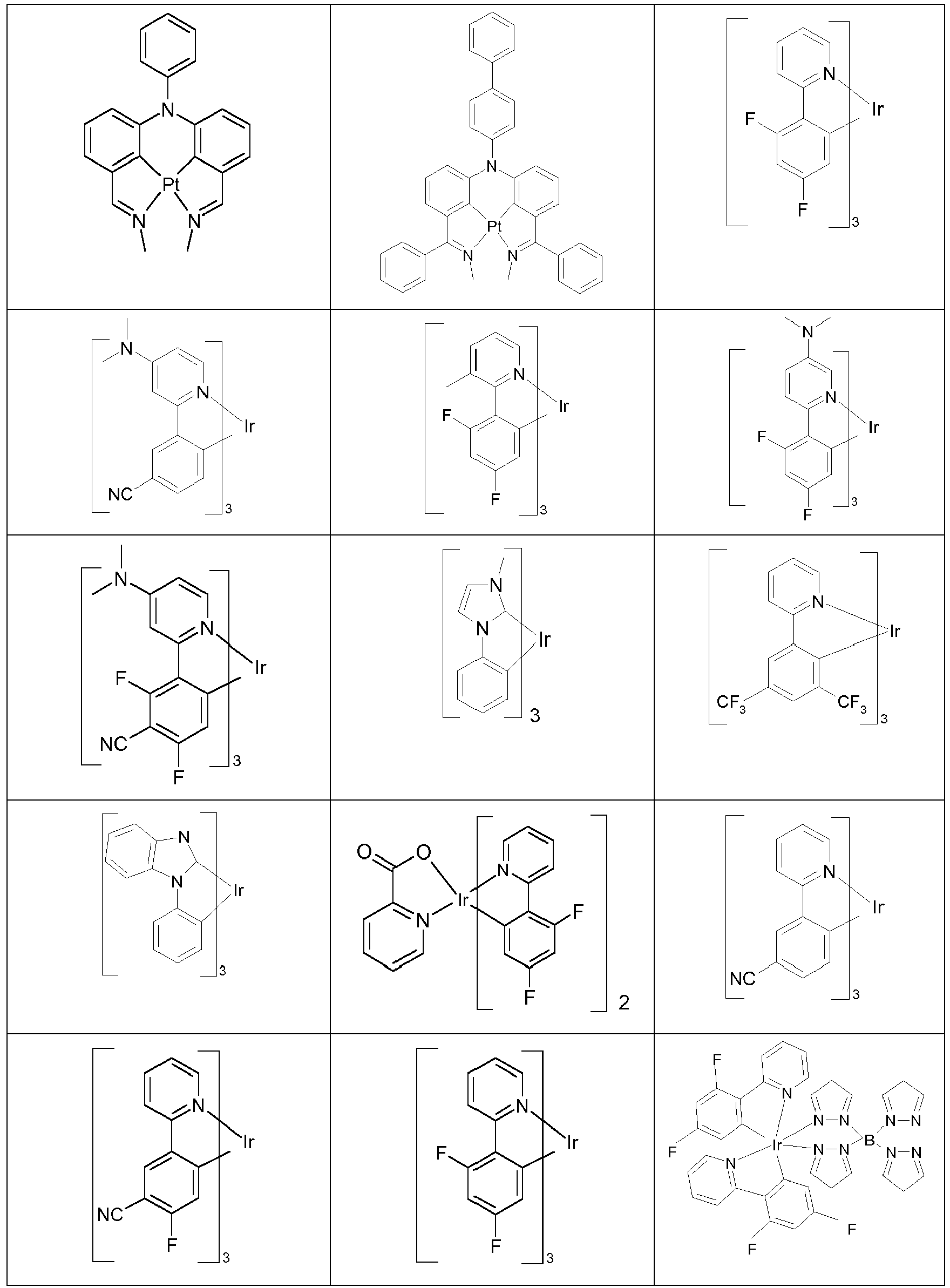

- Bevorzugte fluoreszierende Dotanden sind ausgewählt aus der Klasse der Arylamine. Unter einem Arylamin bzw. einem aromatischen Amin im Sinne dieser Erfindung wird eine Verbindung verstanden, die drei substituierte oder unsubstituierte aromatische oder heteroaromatische Ringsysteme direkt an den Stickstoff gebunden enthält. Bevorzugt ist mindestens eines dieser aromatischen oder heteroaromatischen Ringsysteme ein kondensiertes Ringsystem, besonders bevorzugt mit mindestens 14 aromatischen Ringatomen. Bevorzugte Beispiele hierfür sind aromatische Anthracenamine, aromatische Anthracendiamine, aromatische Pyrenamine, aromatische Pyrendiamine, aromatische Chrysenamine oder aromatische Chrysendiamine. Unter einem aromatischen Anthracenamin wird eine Verbindung verstanden, in der eine Diarylaminogruppe direkt an eine Anthracengruppe gebunden ist, vorzugsweise in 9-Position. Unter einem aromatischen Anthracendiamin wird eine Verbindung verstanden, in der zwei Diarylaminogruppen direkt an eine Anthracengruppe gebunden sind, vorzugsweise in 9,10-Position. Aromatische Pyrenamine, Pyrendiamine, Chrysenamine und Chrysendiamine sind analog dazu definiert, wobei die Diarylaminogruppen am Pyren bevorzugt in 1-Position bzw. in 1,6-Position gebunden sind. Weitere bevorzugte fluoreszierende Dotanden sind gewählt aus Indenofluorenaminen bzw. -diaminen, beispielsweise gemäß
WO 2006/122630 , Benzoindenofluorenaminen bzw. -diaminen, beispielsweise gemäßWO 2008/006449 , und Dibenzoindenofluorenaminen bzw. -diaminen, beispielsweise gemäßWO 2007/140847 . Weiterhin bevorzugt sind die inWO 2010/012328 offenbarten kondensierten Kohlenwasserstoffe. - Geeignete fluoreszierende Dotanden sind weiterhin die in
JP 2006/001973 WO 2004/047499 ,WO 2006/098080 ,WO 2007/065678 ,US 2005/0260442 undWO 2004/092111 offenbarten Derivate dieser Strukturen. - Als Matrixmaterialien, bevorzugt für fluoreszierende Dotanden, kommen Materialien verschiedener Stoffklassen in Frage. Bevorzugte Matrixmaterialien sind ausgewählt aus den Klassen der Oligoarylene (z. B. 2,2',7,7'-Tetraphenylspirobifluoren gemäß
EP 676461 EP 676461 WO 2004/081017 ), der lochleitenden Verbindungen (z. B. gemäßWO 2004/058911 ), der elektronenleitenden Verbindungen, insbesondere Ketone, Phosphinoxide, Sulfoxide, etc. (z. B. gemäßWO 2005/084081 undWO 2005/084082 ), der Atropisomere (z. B. gemäßWO 2006/048268 ), der Boronsäurederivate (z. B. gemäßWO 2006/117052 ) oder der Benzanthracene (z. B. gemäßWO 2008/145239 ). Besonders bevorzugte Matrixmaterialien sind ausgewählt aus den Klassen der Oligoarylene, enthaltend Naphthalin, Anthracen, Benzanthracen und/oder Pyren oder Atropisomere dieser Verbindungen, der Oligoarylenvinylene, der Ketone, der Phosphinoxide und der Sulfoxide. Ganz besonders bevorzugte Matrixmaterialien sind ausgewählt aus den Klassen der Oligoarylene, enthaltend Anthracen, Benzanthracen, Benzphenanthren und/oder Pyren oder Atropisomere dieser Verbindungen. Unter einem Oligoarylen im Sinne dieser Erfindung soll eine Verbindung verstanden werden, in der mindestens drei Aryl- bzw. Arylengruppen aneinander gebunden sind. - Bevorzugte Matrixmaterialien für phosphoreszierende Dotanden sind neben den erfindungsgemäßen Verbindungen Carbazolderivate (z. B. CBP (N,N-Biscarbazolylbiphenyl) oder Verbindungen gemäß
WO 2005/039246 ,US 2005/0069729 ,JP 2004/288381 EP 1205527 oderWO 2008/086851 ), Triarylamine, Azacarbazole (z. B. gemäßEP 1617710 ,EP 1617711 ,EP 1731584 ,JP 2005/347160 WO 2007/063754 oderWO 2008/056746 , Ketone (z. B. gemäßWO 2004/093207 oderWO 2010/006680 ), Phosphinoxide, Sulfoxide und Sulfone (z. B. gemäßWO 2005/003253 ), Oligophenylene, aromatische Amine (z. B. gemäßUS 2005/0069729 ), bipolare Matrixmaterialien (z. B. gemäßWO 2007/137725 ), Silane (z. B. gemäßWO 2005/111172 ), Azaborole oder Boronester, z. B. gemäßWO 2006/117052 , Triazinderivate, z. B. gemäßWO 2010/015306 ,WO 2007/063754 oderWO 2008/056746 , Zinkkomplexe (z. B. gemäßWO 2009/062578 ) Aluminiumkomplexe (z. B. BAlq), Diazasilol- und Tetraazasilol-Derivate, z. B. gemäßWO 2010/054730 , Indenocarbazolderivate, z. B. gemäßWO 2010/136109 undWO 2011/000455 oder Diazaphosphole, z. B. gemäßWO 2010/054730 . - Geeignete Ladungstransportmaterialien, wie sie in der Lochinjektions- bzw. Lochtransportschicht oder in der Elektronentransportschicht der erfindungsgemäßen organischen Elektrolumineszenzvorrichtung verwendet werden können, sind neben den erfindungsgemäßen Verbindungen beispielsweise die in Y. Shirota et al., Chem. Rev. 2007, 107(4), 953-1010 offenbarten Verbindungen oder andere Materialien, wie sie gemäß dem Stand der Technik in diesen Schichten eingesetzt werden.
- Als Kathode sind Metalle mit geringer Austrittsarbeit, Metalllegierungen oder mehrlagige Strukturen aus verschiedenen Metallen bevorzugt, wie beispielsweise Erdalkalimetalle, Alkalimetalle, Hauptgruppenmetalle oder Lanthanoide (z. B. Ca, Ba, Mg, Al, In, Mg, Yb, Sm, etc.). Weiterhin eignen sich Legierungen aus einem Alkali- oder Erdalkalimetall und Silber, beispielsweise eine Legierung aus Magnesium und Silber. Bei mehrlagigen Strukturen können auch zusätzlich zu den genannten Metallen weitere Metalle verwendet werden, die eine relativ hohe Austrittsarbeit aufweisen, wie z. B. Ag oder Al, wobei dann in der Regel Kombinationen der Metalle, wie beispielsweise Ca/Ag, Ba/Ag oder Mg/Ag verwendet werden. Es kann auch bevorzugt sein, zwischen einer metallischen Kathode und dem organischen Halbleiter eine dünne Zwischenschicht eines Materials mit einer hohen Dielektrizitätskonstante einzubringen. Hierfür kommen beispielsweise Alkalimetall- oder Erdalkalimetallfluoride, aber auch die entsprechenden Oxide oder Carbonate in Frage (z. B. LiF, Li2O, BaF2, MgO, NaF, CsF, Cs2CO3, etc.). Weiterhin kann dafür Lithiumchinolinat (LiQ) verwendet werden. Die Schichtdicke dieser Schicht beträgt bevorzugt zwischen 0.5 und 5 nm.
- Als Anode sind Materialien mit hoher Austrittsarbeit bevorzugt. Bevorzugt weist die Anode eine Austrittsarbeit größer 4.5 eV vs. Vakuum auf. Hierfür sind einerseits Metalle mit hohem Redoxpotential geeignet, wie beispielsweise Ag, Pt oder Au. Es können andererseits auch Metall/Metalloxid-Elektroden (z. B. Al/Ni/NiOx, Al/PtOx) bevorzugt sein. Für einige Anwendungen muss mindestens eine der Elektroden transparent oder teiltransparent sein, um entweder die Bestrahlung des organischen Materials (organische Solarzelle) oder die Auskopplung von Licht (OLED, O-LASER) zu ermöglichen. Bevorzugte Anodenmaterialien sind hier leitfähige gemischte Metalloxide. Besonders bevorzugt sind Indium-ZinnOxid (ITO) oder Indium-Zink-Oxid (IZO). Bevorzugt sind weiterhin leitfähige, dotierte organische Materialien, insbesondere leitfähige dotierte Polymere.
- Die Vorrichtung wird entsprechend (je nach Anwendung) strukturiert, kontaktiert und schließlich versiegelt, da sich die Lebensdauer der erfindungsgemäßen Vorrichtungen bei Anwesenheit von Wasser und/oder Luft verkürzt.
- In einer bevorzugten Ausführungsform ist die erfindungsgemäße organische Elektrolumineszenzvorrichtung dadurch gekennzeichnet, dass eine oder mehrere Schichten mit einem Sublimationsverfahren beschichtet werden. Dabei werden die Materialien in Vakuum-Sublimationsanlagen bei einem Anfangsdruck kleiner 10-5 mbar, bevorzugt kleiner 10-6 mbar aufgedampft. Dabei ist es jedoch auch möglich, dass der Anfangsdruck noch geringer ist, beispielsweise kleiner 10-7 mbar.
- Bevorzugt ist ebenfalls eine organische Elektrolumineszenzvorrichtung, dadurch gekennzeichnet, dass eine oder mehrere Schichten mit dem OVPD (Organic Vapour Phase Deposition) Verfahren oder mit Hilfe einer Trägergassublimation beschichtet werden. Dabei werden die Materialien bei einem Druck zwischen 10-5 mbar und 1 bar aufgebracht. Ein Spezialfall dieses Verfahrens ist das OVJP (Organic Vapour Jet Printing) Verfahren, bei dem die Materialien direkt durch eine Düse aufgebracht und so strukturiert werden (z. B. M. S. Arnold et al., Appl. Phys. Lett. 2008, 92, 053301).
- Weiterhin bevorzugt ist eine organische Elektrolumineszenzvorrichtung, dadurch gekennzeichnet, dass eine oder mehrere Schichten aus Lösung, wie z. B. durch Spincoating, oder mit einem beliebigen Druckverfahren, wie z. B. Siebdruck, Flexodruck, Nozzle Printing oder Offsetdruck, besonders bevorzugt aber LITI (Light Induced Thermal Imaging, Thermotransferdruck) oder Ink-Jet Druck (Tintenstrahldruck), hergestellt werden. Hierfür sind lösliche Verbindungen gemäß Formel (I), (II) oder (III) nötig. Hohe Löslichkeit lässt sich durch geeignete Substitution der Verbindungen erreichen.
- Weiterhin bevorzugt ist es, dass zur Herstellung einer erfindungsgemäßen organischen Elektrolumineszenzvorrichtung eine oder mehrere Schichten aus Lösung und eine oder mehrere Schichten durch ein Sublimationsverfahren aufgetragen werden.
- Die organischen Elektrolumineszenzvorrichtungen enthaltend eine oder mehrere erfindungsgemäße Verbindungen können in Displays, als Lichtquellen in Beleuchtungsanwendungen sowie als Lichtquellen in medizinischen und/oder kosmetischen Anwendungen (z.B. Lichttherapie) eingesetzt werden.
- Die erfindungsgemäßen Verbindungen zeichnen sich insbesondere dadurch aus, dass sie bei Verwendung in organischen Elektrolumineszenzvorrichtungen gute Leistungseffizienzen, geringe Betriebsspannungen und lange Lebensdauern der Vorrichtungen bewirken.
- Weiterhin sind die Verbindungen oxidationsstabil, temperaturstabil und weisen eine hohe Glasübergangstemperatur auf, was sowohl für die Prozessierbarkeit, beispielsweise aus Lösung oder aus der Gasphase, als auch für die Verwendung in elektronischen Vorrichtungen vorteilhaft ist.
- Weiterhin weisen die Verbindungen ein hochliegendes angeregtes Triplettniveau auf, was insbesondere bei Verwendung in einer emittierenden Schicht in Kombination mit einer phosphoreszierenden Emitterverbindung hoch erwünscht ist. Insbesondere weisen die Verbindungen ein höheres angeregtes Triplettniveau auf als die entsprechenden 2-Fluorenyl-Derivate.
- Weiterhin weisen die Verbindungen eine hohe Lochbeweglichkeit auf, was insbesondere bei der Verwendung als Lochtransportmaterial bzw. Lochinjektionsmaterial hoch erwünscht ist.
- Die Erfindung wird durch die nachfolgenden Anwendungsbeispiele näher erläutert, wobei die Erfindung nicht auf den Umfang der Beispiele beschränkt ist.
- Die nachfolgenden Synthesen werden, sofern nicht anders angegeben, unter einer Schutzgasatmosphäre durchgeführt. Die Edukte können von den Firmen ALDRICH bzw. ABCR (Palladium(II)acetat, Tri-o-tolylphosphin, Anorganika, Lösemittel) bezogen werden. Die Synthese von 3-Bromfluorenon (Tetrahedron, 51,7, 2039-54; 1995) und 3-Bromfluoren kann gemäß der Literatur (Tetrahedron Letters, 51,37, 4894-4897; 2010) erfolgen, ebenfalls die Synthese von Bis-biphenyl-4-yl-(4'-bromo-biphenyl-4-yl)-amin (
JP 2010-111605 -

- Eine gut gerührte, unter Rückfluss kochende Suspension von 64 g (250 mmol) 3-Bromfluoren in einem Gemisch von 1000 ml Toluol und 2000 ml Ethanol wird mit 49 ml (1000 mmol) Hydrazinhydrat und dann mit 3 g frisch bereitetem Raney-Nickel versetzt. Nach 2 h unter Rückfluss lässt man die Mischung erkalten, entfernt das Lösemittel im Vakuum, nimmt den Rückstand in 1000 ml warmem Chloroform auf, filtriert die Lösung über Kieselgel, engt die klare Lösung auf 100 ml ein und gibt 300 ml Ethanol zu. Nach 12 h Stehenlassen werden die farblosen Kristalle abgesaugt und anschließend zweimal aus Chloroform/Ethanol umkristallisiert. Ausbeute: 60 g (240 mmol), 98 % d. Th.; Reinheit: 97 % nach 1H-NMR.
-

- 37 g (152 mmol) 3-Bromo-9H-fluoren werden in einem ausgeheizten Kolben in 600 mL getrocknetem DMSO gelöst. Bei Raumtemperatur werden 43.9 g (457 mmol) NaO t Bu zugegeben. Die nunmehr blaue Suspension wird auf eine Innentemperatur von 80 °C gebracht. Bei dieser Temperatur werden zur jetzt violetten Lösung 64.8 g (457 mmol) lodmethan so zugetropft, dass die Innentemperatur 90 °C nicht übersteigt (Dauer: ca. 30 min). Der Ansatz wird für weitere 30 min bei 80-90 °C Innentemperatur gehalten, dann auf 1500 mL Eiswasser gegossen und ca. 20 min gerührt. Der ausgefallene Feststoff wird abgesaugt und nacheinander mit ca. 200 mL H2O und Methanol gewaschen. Ausbeute: 39 g (144 mmol), 96 % d. Th.; Reinheit: 95 % n. 1H-NMR.
-

- Das Grignardreagenz, bereitet aus 9.9 g (400 mmol) Magnesiumspänen und 93.2 g (68 ml, 400 mmol) 2-Brombiphenyl in 500 ml trockenem Diethylether, wird im Verlauf von 2 h zu einer siedenden Lösung von 103 g (400 mmol) 3-Brom-9-fluorenon in 100 ml trockenem Diethylether getropft. Nach beendeter Zugabe wird 3 Stunden weiter zum Sieden erhitzt. Nach Abkühlung über Nacht wird der ausgefallene Niederschlag abgesaugt und mit kaltem Ether gewaschen. Der Rückstand wird in einer Lösung von 15 g Ammoniumchlorid in 250 ml Eiswasser hydrolysiert. Nach 1 h wird der gebildete Alkohol abgesaugt, mit Wasser gewaschen und trockengesaugt.
- Das getrocknete Fluorenol wird für die Ringschlußreaktion in 100 ml Eisessig, nach Zugabe von 3 Tropfen HCl conc. 6 Stunden gekocht. Man lässt über Nacht kristallisieren, saugt das gebildete Produkt ab und wäscht mit Eisessig und Wasser. Ausbeute: 141 g (356 mmol), 95 % d. Th.; Reinheit: 96 % n. 1H-NMR.
-

- 70 g (259 mmol) 3-Brom-9,9-dimethyl-9H-fluoren werden in 1500 mL trockenem THF gelöst, bei -70 °C werden 135 mL (337 mmol) einer 2.5 M Lösung von n-Butyllithium in Cyclohexan zugetropft und nach 1 h werden 37 mL Trimethylborat (336 mmol) zugetropft. Man lässt innerhalb 1 h auf Raumtemperatur kommen und entfernt das Lösungsmittel. Der Rückstand, der nach 1H-NMR einheitlich ist, wird ohne weitere Reinigung in die Folgereaktion eingesetzt. Die Ausbeute beträgt 55 g (230 mmol), entsprechend 90 % der Theorie.
- Analog werden die Vorstufen E und F erhalten:
Bsp. Edukt 1 Produkt Ausbeute E 

88 % F 

69% 1161009-88-6 -

- Analog werden die Vorstufen H und I erhalten:
Bsp. Edukt 1 Produkt Ausbeute H 

81 % I 

66% -

- 50 g (183 mmol) 3-Brom-9,9-dimethyl-9H-fluoren, 20ml (220 mmol) Anilin, 1.5 g (2.7 mmol) DPPF, 0.5 g Palladium(II)acetat und 45 g (486 mmol) Natrium-tert-butylat werden in 1.5 L Toluol 18 h unter Schutzatmosphäre zum Sieden erhitzt. Das Gemisch wird im Anschluss zwischen Toluol und Wasser verteilt, die organische Phase wird dreimal mit Wasser gewaschen und über Na2SO4 getrocknet und einrotiert. Der verbleibende Rückstand wird aus Heptan/Essigester umkristallisiert. Die Ausbeute beträgt 31.2 g (110 mmol, 52%). Ausbeute: 46 g (165 mmol), 78 % d. Th.; Reinheit: 97% n. 1H-NMR.
- Analog werden die Verbindungen K bis X erhalten:
Bsp. Edukt 1 Edukt 2 Produkt Ausbeute K 


81 % 3315-50-2 L 


85% 3315-50-2 M 


73% 90-41-5 N 


75% 108714-73-4 O 


70% P 


71% Q 


86% R 


89% S 


72% 942615-32-9 T 


75% 1225053-54-2 U 


79% 942615-32-9 3315-50-2 V 


72% 942615-32-9 3315-50-2 W 

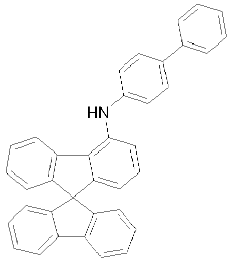
70% 3315-50-2 X 


65% 108714-73-4 -

- Eine entgaste Lösung von 48 g (87 mmol) Bis-biphenyl-4-yl-(4'-brombiphenyl-4-yl)-amin und 23 g (80 mmol) (9,9-Dimethyl-9H-fluoren-3-yl)-phenylamin in 1000 mL Dioxan wird 1 h mit N2 gesättigt. Danach wird die Lösung zuerst mit 0.9 mL (4.3 mmol) P(tBu)3, dann mit 0.48 g (2.1 mmol) Palladium(II)acetat versetzt. Anschließend wird 12.6 g (131 mmol) NaOtBu im festen Zustand zugegeben. Die Reaktionsmischung wird 18 h unter Rückfluss erhitzt. Nach Abkühlen auf Raumtemperatur werden vorsichtig 1000 mL Wasser zugesetzt. Die organische Phase wird mit 4 x 50 mL Wasser gewaschen, über MgSO4 getrocknet und das Lösungsmittel im Vakuum entfernt. Das reine Produkt erhält man durch Umkristallisation und abschließende Sublimation. Ausbeute: 46 g (61 mmol), 71% d. Th., Reinheit nach HPLC 99.9%.
- Analog werden die Verbindungen 2 bis 18 erhalten:
Bsp. Edukt 1 Edukt 2 Produkt Ausbeute 2 


83 % 212385-73-4 3 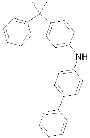


80% 1028648-25-0 4 


84% 1028647-93-9 5 


80% 728039-63-2 6 


77% 765271-17-8 7 


72% 1028647-93-9 8 


65% 1028648-25-0 9 


84% 1028647-93-9 10 


78% 1028647-93-9 11 


69% 308144-66-3 12 


63% 1028648-25-0 13 


73% 728039-63-2 14 


76% 1072194-21-8 942615-32-9 15 

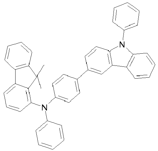
77% 1072194-21-8 1225053-54-2 16 


79% 1072194-21-8 17 


73% 1072194-21-8 713125-22-5 18 

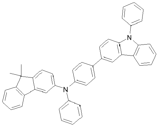
76% 1072194-21-8 - Die Herstellung von erfindungsgemäßen OLEDs sowie OLEDs nach dem Stand der Technik erfolgt nach einem allgemeinen Verfahren gemäß
WO 2004/058911 , das auf die hier beschriebenen Gegebenheiten (Schichtdickenvariation, Materialien) angepasst wird. - In den folgenden Beispielen E1 bis E16 (siehe Tabellen 3 und 5 mit Devicedaten und Tabellen 2 und 4 mit den entsprechenden Angaben zu den Devicestrukturen) werden die Daten verschiedener OLEDs vorgestellt. Glasplättchen, die mit strukturiertem ITO (Indium Zinn Oxid) der Dicke 150 nm beschichtet sind, werden zur verbesserten Prozessierung mit 20 nm PEDOT beschichtet (Poly(3,4-ethylendioxy-2,5-thiophen), aus Wasser aufgeschleudert; bezogen von H. C. Starck, Goslar, Deutschland). Diese beschichteten Glasplättchen bilden die Substrate, auf welche die OLEDs aufgebracht werden. Die OLEDs haben prinzipiell folgenden Schichtaufbau: Substrat / Optionale Lochinjektionsschicht (HIL) / Lochtransportschicht (HTL) / Optionale Zwischenschicht (IL) / Elektronenblockerschicht (EBL) / Emissionsschicht (EML) / Optionale Lochblockierschicht (HBL) / Elektronentransportschicht (ETL) / Optionale Elektroneninjektionsschicht (EIL) und abschließend eine Kathode. Die Kathode wird durch eine 100 nm dicke Aluminiumschicht gebildet. Der genaue Aufbau der OLEDs ist den Tabellen 2 und 4 zu entnehmen. Die zur Herstellung der OLEDs benötigten Materialien sind in Tabelle 1 gezeigt.
- Alle Materialien werden in einer Vakuumkammer thermisch aufgedampft. Dabei besteht die Emissionsschicht immer aus mindestens einem Matrixmaterial (Hostmaterial, Wirtsmaterial) und einem emittierenden Dotierstoff (Dotand, Emitter), der dem Matrixmaterial bzw. den Matrixmaterialien durch Coverdampfung in einem bestimmten Volumenanteil beigemischt wird. Eine Angabe wie H1:SEB1 (95%:5%) bedeutet hierbei, dass das Material H1 in einem Volumenanteil von 95% und SEB1 in einem Anteil von 5% in der Schicht vorliegt. Analog kann auch die Elektronentransportschicht aus einer Mischung von zwei Materialien bestehen.
- Die OLEDs werden standardmäßig charakterisiert. Hierfür werden die Elektrolumineszenzspektren, die Stromeffizienz (gemessen in cd/A), die Leistungseffizienz (gemessen in Im/W) und die externe Quanteneffizienz (EQE, gemessen in Prozent) in Abhängigkeit der Leuchtdichte, berechnet aus Strom-Spannungs-Leuchtdichte-Kennlinien (IUL-Kennlinien) unter Annahme einer lambertschen Abstrahlcharakteristik sowie die Lebensdauer bestimmt. Die Elektrolumineszenzspektren werden bei einer Leuchtdichte von 1000 cd/m2 bestimmt und daraus die CIE 1931 x und y Farbkoordinaten berechnet. Die Angabe U @ 1000 cd/m2 in Tabelle 3 und 5 bezeichnet die Spannung, die für eine Leuchtdichte von 1000 cd/m2 benötigt wird. EQE @ 1000 cd/m2 schließlich bezeichnet die externe Quanteneffizienz bei einer Betriebsleuchtdichte von 1000 cd/m2. LD80 @ 6000 cd/m2 ist die Lebensdauer bis das OLED bei einer Helligkeit von 6000 cd/m2 auf 80 % der Anfangsintensität, also auf 4800 cd/m2 abgefallen ist. Die Devicedaten der verschiedenen OLEDs sind in Tabelle 3 und 5 zusammengefasst, während die Tabellen 2 und 4 die entsprechenden Device-Aufbauten wiedergeben.
- Insbesondere eignen sich erfindungsgemäße Verbindungen als Lochtransportmaterial (HTM), als Matrixmaterial oder als Elektronenblockiermaterial (EBM) in OLEDs. Sie eignen sich zur Verwendung als Einzelmaterialien in einer Schicht, aber auch zur Verwendung in Mischung mit einer oder mehreren weiteren Komponenten in der Lochtransportschicht (HTL), Elektronenblockierschicht (EBL) oder emittierenden Schicht (EML).
- Verglichen mit Vorrichtungen enthaltend NPB als EBM (V1 und V5) zeigen die Vorrichtungen enthaltend erfindungsgemäße Verbindungen (E1 bis E16) sowohl höhere Effizienzen als auch verbesserte Lebensdauern.
- Verglichen mit dem Material gemäß dem Stand der Technik HTMV1 (V2), bei welchem die Carbazol- und die Fluorengruppe direkt über eine Aminogruppe miteinander verbunden sind, zeigen die erfindungsgemäßen Verbindungen ähnliche oder bessere Effizienzen und deutlich bessere Lebensdauern. So ist die Lebensdauer der Referenz-Vorrichtung V2 im Vergleich zu E1 und E2 (blau fluoreszierende Vorrichtungen) nahezu 10-fach länger und auch in der grün phosphoreszierenden Vorrichtung (V6 verglichen mit E9 und E10) ergibt sich noch nahezu eine Verdopplung der Lebensdauer.
- Der Vorteil einer 3-Fluoren-Substitution im Vergleich zu einer 2-Fluoren-Substitution ist gut im Vergleich zwischen HTMV2 und HTM6 zu erkennen. In den blau fluoreszierenden Vorrichtungen (V3 und E6) und insbesondere in den grün phosphoreszierenden Vorrichtungen (V7 und E14) zeigen sich bessere Effizienzen und bessere Lebensdauern. Das gleiche ist auch gut im Vergleich von HTMV3 (V8) gegen HTM7 (E15) und HTM8 (E16) zu erkennen. Auch hier zeigt sich insbesondere bei grün phosphoreszierenden Vorrichtungen eine deutlich verbesserte Effizienz und Lebensdauer.
- Die oben diskutierten Vorrichtungen wurden lediglich beispielhaft hervorgehoben. Ähnliche Effekte können auch bei den anderen, nicht explizit diskutierten Vorrichtungen beobachtet werden, wie aus den Tabellen mit den Devicedaten ersichtlich ist. Allgemein stellen die mit V1 bis V8 bezeichneten Vorrichtungen Vergleichsbeispiele enthaltend Verbindungen gemäß dem Stand der Technik dar. Die mit E1 bis E16 bezeichneten Vorrichtungen enthalten Verbindungen gemäß der vorliegenden Erfindung und sind somit erfindungsgemäße Beispiele.
Tabelle 1: Strukturen der verwendeten Materialien 


HIL1 HIL2 NPB 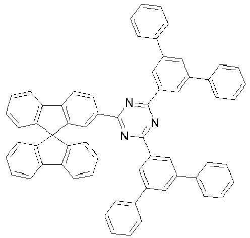


ETM1 Alq3 H1 


SEB1 LiQ H2 
Irpy 


HTMV1 HTMV2 HTMV3 


HTM1 (Verbindung 3) HTM2 (Verbindung 4) HTM3 (Verbindung 7) 


HTM4 (Verbindung 9) HTM5 (Verbindung 10) HTM6 (Verbindung 5) 
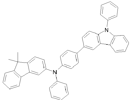
HTM7 (Verbindung 16) HTM8 (Verbindung 18) Tabelle 2: Aufbau der OLEDs Bsp. IL HTL IL HTL2 EBL EML ETL Dicke / nm Dicke / nm Dicke / nm Dicke / nm Dicke / nm Dicke / nm Dicke / nm V1 HIL1 HIL2 HIL1 NPB H1(95%):SEB1(5%) ETM1 (50%):LiQ(50%) 5 nm 140 nm 5 nm 20 nm 20 nm 30 nm V2 HIL1 HIL2 HIL1 HTMV1 H1(95%):SEB1(5%) ETM1 (50%):LiQ(50%) 5 nm 140 nm 5 nm 20 nm 20 nm 30 nm V3 HIL1 HIL2 HIL1 HTMV2 H1(95%):SEB1(5%) ETM1 (50%):LiQ(50%) 5 nm 140 nm 5 nm 20 nm 20 nm 30 nm V4 HIL1 HIL2 HIL1 HTMV3 H1(95%):SEB1(5%) ETM1 (50%):LiQ(50%) 5 nm 140 nm 5 nm 20 nm 20 nm 30 nm E1 HIL1 HIL2 HIL1 HTM1 H1(95%):SEB1(5%) ETM1 (50%):LiQ(50%) 5 nm 140 nm 5 nm 20 nm 20 nm 30 nm E2 HIL1 HIL2 HIL1 HTM2 H1(95%):SEB1(5%) ETM1(50%):LiQ(50%) 5 nm 140 nm 5 nm 20 nm 20 nm 30 nm E3 HIL1 HIL2 HIL1 HTM3 H1(95%):SEB1(5%) ETM1 (50%):LiQ(50%) 5 nm 140 nm 5 nm 20 nm 20 nm 30 nm E4 HIL1 HIL2 HIL1 NPB HTM4 H1(95%):SEB1(5%) ETM1 (50%):LiQ(50%) 5 nm 130 nm 5 nm 10 nm 20 nm 20 nm 30 nm E5 HIL1 HIL2 HIL1 NPB HTM5 H1(95%):SEB1(5%) ETM1 (50%):LiQ(50%) 5 nm 130 nm 5 nm 10 nm 20 nm 20 nm 30 nm E6 HIL1 HIL2 HIL1 HTM6 H1(95%):SEB1(5%) ETM1 (50%):LiQ(50%) 5 nm 140 nm 5 nm 20 nm 20 nm 30 nm E7 HIL1 HIL2 HIL1 HTM7 H1(95%):SEB1(5%) ETM1 (50%):LiQ(50%) 5 nm 140 nm 5 nm 20 nm 20 nm 30 nm E8 HIL1 HIL2 HIL1 HTM8 H1(95%):SEB1(5%) ETM1 (50%):LiQ(50%) 5 nm 140 nm 5 nm 20 nm 20 nm 30 nm Tabelle 3: Daten der OLEDs Bsp. U @ 1000 cd/m2 EQE @ 1000 cd/m2 LD80 @ 6000 cd/m2 CIE V % [h] x y V1 4.7 4.8 70 0.14 0.17 V2 4.4 6.5 10 0.14 0.16 V3 4.6 5.9 60 0.14 0.16 V4 4.5 6.7 90 0.14 0.16 E1 4.5 6.8 105 0.14 0.16 E2 4.4 6.9 110 0.14 0.16 E3 4.5 6.8 105 0.14 0.15 E4 4.6 7.0 120 0.14 0.16 E5 4.6 6.9 110 0.14 0.16 E6 4.5 6.6 80 0.14 0.16 E7 4.5 6.8 100 0.14 0.16 E8 4.5 6.9 95 0.14 0.16 Tabelle 4: Aufbau der OLEDs Bsp. HTL IL HTL2 EBL EML ETL Dicke / nm Dicke / nm Dicke / nm Dicke / nm Dicke / nm Dicke / nm V5 HIL2 HIL1 NPB H2(88%):Irpy(12%) ETM1 (50%):LiQ(50%) 70 nm 5 nm 90 nm 30 nm 40 nm V6 HIL2 HIL1 HTMV1 H2(88%):Irpy(12%) ETM1 (50%):LiQ(50%) 70 nm 5 nm 90 nm 30 nm 40 nm V7 HIL2 HIL1 HTMV2 H2(88%):Irpy(12%) ETM1 (50%):LiQ(50%) 70 nm 5 nm 90 nm 30 nm 40 nm V8 HIL2 HIL1 HTMV3 H2(88%):Irpy(12%) ETM1 (50%):LiQ(50%) 70 nm 5 nm 90 nm 30 nm 40 nm E9 HIL2 HIL1 HTM1 H2(88%):Irpy(12%) ETM1 (50%):LiQ(50%) 70 nm 5 nm 90 nm 30 nm 40 nm E10 HIL2 HIL1 HTM2 H2(88%):Irpy(12%) ETM1 (50%):LiQ(50%) 70 nm 5 nm 90 nm 30 nm 40 nm E11 HIL2 HIL1 HTM3 H2(88%):Irpy(12%) ETM1 (50%):LiQ(50%) 70 nm 5 nm 90 nm 30 nm 40 nm E12 HIL2 HIL1 NPB HTM4 H2(88%):Irpy(12%) ETM1 (50%):LiQ(50%) 70 nm 5 nm 10 nm 80 nm 30 nm 40 nm E13 HIL2 HIL1 NPB HTM5 H2(88%):Irpy(12%) ETM1 (50%):LiQ(50%) 70 nm 5 nm 10 nm 80 nm 30 nm 40 nm E14 HIL2 HIL1 HTM6 H2(88%):Irpy(12%) ETM1 (50%):LiQ(50%) 70 nm 5 nm 90 nm 30 nm 40 nm E15 HIL2 HIL1 HTM7 H2(88%):Irpy(12%) ETM1 (50%):LiQ(50%) 70 nm 5 nm 90 nm 30 nm 40 nm E16 HIL2 HIL1 HTM8 H2(88%):Irpy(12%) ETM1 (50%):LiQ(50%) 70 nm 5 nm 90 nm 30 nm 40 nm Tabelle 5: Daten der OLEDs Bsp. U @ 1000 cd/m2 Effizienz @ 1000 cd/m2 LD80 @ 8000 cd/m2 CIE V % [h] x y V5 3.6 14.4 85 0.32 0.63 V6 3.4 16.8 70 0.33 0.64 V7 3.4 15.6 120 0.33 0.64 V8 3.5 16.7 135 0.33 0.63 E9 3.3 17.6 155 0.34 0.62 E10 3.3 17.8 160 0.33 0.63 E11 3.4 17.0 145 0.33 0.64 E12 3.5 17.5 155 0.34 0.63 E13 3.5 17.8 160 0.34 0.63 E14 3.4 16.4 145 0.33 0.63 E15 3.5 17.6 155 0.33 0.64 E16 3.4 17.8 150 0.33 0.63
wobei n in Formel (II) gleich 1 sein muss, wenn die Gruppe X eine Einfachbindung darstellt; und
wobei die Verbindung keine Heteroarylgruppe enthalten darf, welche mehr als 14 aromatische Ringatome enthält.
Claims (17)
- Verbindung der Formel (I)
 A ist gleich C(R1)2;wobei das Stickstoffatom in 1-Position, in 3-Position oder in 4-Position am Fluoren-Ringsystem gebunden ist; undZ ist bei jedem Auftreten gleich oder verschieden CR1 oder N oder, wenn eine Gruppe in der betreffenden Position gebunden ist, gleich C;Ar3 ist ein aromatisches oder heteroaromatisches Ringsystem mit 5 bis 30 aromatischen Ringatomen, welches mit einem oder mehreren Resten R1 substituiert sein kann;Ar2 ist bei jedem Auftreten gleich oder verschieden eine Arylengruppe mit 6 bis 30 aromatischen Ringatomen oder eine Heteroarylengruppe mit 5 bis 14 aromatischen Ringatomen, welche mit einem oder mehreren Resten R1 substituiert sein kann;Ar4 ist bei jedem Auftreten gleich oder verschieden eine Arylgruppe mit 6 bis 30 aromatischen Ringatomen oder eine Heteroarylgruppe mit 5 bis 14 aromatischen Ringatomen, welche mit einem oder mehreren Resten R1 substituiert sein kann, wobei Reste R1 an Gruppen Ar4 keine Ringe bilden dürfen;R1 ist bei jedem Auftreten gleich oder verschieden H, D, F, Cl, Br, I, B(OR2)2, CHO, C(=O)R2, CR2=C(R2)2, CN, C(=O)OR2, C(=O)N(R2)2, Si(R2)3, N(R2)2, NO2, P(=O)(R2)2, OSO2R2, OR2, S(=O)R2, S(=O)2R2, eine geradkettige Alkyl-, Alkoxy- oder Thioalkylgruppe mit 1 bis 20 C-Atomen oder eine verzweigte oder cyclische Alkyl-, Alkoxy- oder Thioalkylgruppe mit 3 bis 20 C-Atomen oder eine Alkenyl- oder Alkinylgruppe mit 2 bis 20 C-Atomen, wobei die oben genannten Gruppen jeweils mit einem oder mehreren Resten R2 substituiert sein können und wobei eine oder mehrere CH2-Gruppen in den oben genannten Gruppen durch -R2C=CR2-, -C=C-, Si(R2)2, C=O, C=S, C=NR2, -C(=O)O-, -C(=O)NR2-, NR2, P(=O)(R2), -O-, -S-, SO oder SO2 ersetzt sein können und wobei ein oder mehrere H-Atome in den oben genannten Gruppen durch D, F, Cl, Br, I, CN oder NO2 ersetzt sein können, oder ein aromatisches oder heteroaromatisches Ringsystem mit 5 bis 30 aromatischen Ringatomen, das jeweils durch einen oder mehrere Reste R2 substituiert sein kann, oder eine Aryloxy- oder Heteroaryloxygruppe mit 5 bis 30 aromatischen Ring-atomen, die durch einen oder mehrere Reste R2 substituiert sein kann, wobei zwei oder mehr Reste R1 miteinander verknüpft sein können und einen Ring bilden können;R2 ist bei jedem Auftreten gleich oder verschieden H, D, F, Cl, Br, I, B(OR3)2, CHO, C(=O)R3, CR3=C(R3)2, CN, C(=O)OR3, C(=O)N(R3)2, Si(R3)3, N(R3)2, NO2, P(=O)(R3)2, OSO2R3, OR3, S(=O)R3, S(=O)2R3, eine geradkettige Alkyl-, Alkoxy- oder Thioalkylgruppe mit 1 bis 20 C-Atomen oder eine verzweigte oder cyclische Alkyl-, Alkoxy- oder Thioalkylgruppe mit 3 bis 20 C-Atomen oder eine Alkenyl- oder Alkinylgruppe mit 2 bis 20 C-Atomen, wobei die oben genannten Gruppen jeweils mit einem oder mehreren Resten R3 substituiert sein können und wobei eine oder mehrere CH2-Gruppen in den oben genannten Gruppen durch -R3C=CR3-, -C=C-, Si(R3)2, C=O, C=S, C=NR3, -C(=O)O-, -C(=O)NR3-, NR3, P(=O)(R3), -O-, -S-, SO oder SO2 ersetzt sein können und wobei ein oder mehrere H-Atome in den oben genannten Gruppen durch D, F, Cl, Br, I, CN oder NO2 ersetzt sein können, oder ein aromatisches oder heteroaromatisches Ringsystem mit 5 bis 30 aromatischen Ringatomen, das jeweils durch einen oder mehrere Reste R3 substituiert sein kann, oder eine Aryloxy- oder Heteroaryloxygruppe mit 5 bis 30 aromatischen Ring-atomen, die durch einen oder mehrere Reste R3 substituiert sein kann, wobei zwei oder mehr Reste R2 miteinander verknüpft sein können und einen Ring bilden können;R3 ist bei jedem Auftreten gleich oder verschieden H, D, F oder ein aliphatischer, aromatischer oder heteroaromatischer organischer Rest mit 1 bis 20 C-Atomen, in dem auch ein oder mehrere H-Atome durch D oder F ersetzt sein können; dabei können zwei oder mehr Substituenten R3 miteinander verknüpft sein und einen Ring bilden;m ist gleich 0, was bedeutet, dass die betreffende Gruppe nicht vorhanden ist;n ist gleich 1, 2 oder 3;
wobei die Verbindung keine Heteroarylgruppe enthalten darf, welche mehr als 14 aromatische Ringatome enthält. - Verbindung nach Anspruch 1, dadurch gekennzeichnet, dass die Gruppe N(Ar3) in 3-Position am Fluorenyl-Ringsystem gebunden ist.
- Verbindung nach Anspruch 1 oder 2, dadurch gekennzeichnet, dass Ar3 ein aromatisches Ringsystem mit 6 bis 18 aromatischen Ringatomen ist, das mit einem oder mehreren Resten R1 substituiert sein kann.
- Verbindung nach einem oder mehreren der Ansprüche 1 bis 3, dadurch gekennzeichnet, dass Ar4 bei jedem Auftreten gleich oder verschieden gewählt ist aus Arylgruppen mit 6 bis 30 aromatischen Ringatomen, die mit einem oder mehreren Resten R1 substituiert sein können, bevorzugt dadurch gekennzeichnet, dass Ar4 bei jedem Auftreten gleich oder verschieden gewählt ist aus Phenylgruppen, die mit einem oder mehreren Resten R1 substituiert sein können.
- Verbindung nach einem oder mehreren der Ansprüche 1 bis 4, dadurch gekennzeichnet, dass Ar2 eine Phenylengruppe darstellt, welche mit einem oder mehreren Resten R1 substituiert sein kann.
- Verbindung nach einem oder mehreren der Ansprüche 1 bis 5, dadurch gekennzeichnet, dass R1 bei jedem Auftreten gleich oder verschieden ausgewählt ist aus H, D, F, CN, Si(R2)3, N(R2)2, einer geradkettigen Alkyl- oder Alkoxygruppe mit 1 bis 20 C-Atomen, oder einer verzweigten oder cyclischen Alkyl- oder Alkoxygruppe mit 3 bis 20 C-Atomen, wobei die oben genannten Gruppen jeweils mit einem oder mehreren Resten R2 substituiert sein können und wobei in den oben genannten Gruppen eine oder mehrere CH2-Gruppen durch - C=C-, -R2C=CR2-, Si(R2)2, C=O, C=NR2, -NR2-, -O-, -S-, -C(=O)O- oder -C(=O)NR2- ersetzt sein können, oder einem aromatischen oder heteroaromatischen Ringsystem mit 5 bis 20 aromatischen Ringatomen, das jeweils mit einem oder mehreren Resten R2 substituiert sein kann, und bevorzugt dadurch gekennzeichnet, dass R1 bei jedem Auftreten gleich oder verschieden ausgewählt ist aus H, D, F, CN, Si(R2)3, N(R2)2, einer geradkettigen Alkylgruppe mit 1 bis 20 C-Atomen, oder einer verzweigten oder cyclischen Alkylgruppe mit 3 bis 20 C-Atomen, wobei die oben genannten Gruppen jeweils mit einem oder mehreren Resten R2 substituiert sein können, oder einem aromatischen oder heteroaromatischen Ringsystem mit 5 bis 20 aromatischen Ringatomen, das jeweils mit einem oder mehreren Resten R2 substituiert sein kann.
- Verbindung nach einem oder mehreren der Ansprüche 1 bis 6, dadurch gekennzeichnet, dass R2 bei jedem Auftreten gleich oder verschieden gewählt ist aus H, D, F, CN, Si(R3)3, N(R3)2, einer geradkettigen Alkyl- oder Alkoxygruppe mit 1 bis 20 C-Atomen, oder einer verzweigten oder cyclischen Alkyl- oder Alkoxygruppe mit 3 bis 20 C-Atomen, wobei die oben genannten Gruppen jeweils mit einem oder mehreren Resten R3 substituiert sein können und wobei in den oben genannten Gruppen eine oder mehrere CH2-Gruppen durch - C=C-, -R3C=CR3-, Si(R3)2, C=O, C=NR3, -NR3-, -O-, -S-, -C(=O)O- oder -C(=O)NR3- ersetzt sein können, oder einem aromatischen oder heteroaromatischen Ringsystem mit 5 bis 20 aromatischen Ringatomen, das jeweils mit einem oder mehreren Resten R3 substituiert sein kann, und bevorzugt dadurch gekennzeichnet, dass R2 bei jedem Auftreten gleich oder verschieden gewählt ist aus H, D, F, CN, einer geradkettigen Alkylgruppe mit 1 bis 20 C-Atomen, einer verzweigten oder cyclischen Alkylgruppe mit 3 bis 20 C-Atomen, oder einem aromatischen oder heteroaromatischen Ringsystem mit 5 bis 20 aromatischen Ringatomen.
- Verbindung nach einem oder mehreren der Ansprüche 1 bis 7, dadurch gekennzeichnet, dass Z gleich CR1 ist, wenn keine Gruppe in der betreffenden Position gebunden ist, und dass Z gleich C ist, wenn eine Gruppe in der betreffenden Position gebunden ist.
- Verbindung nach einem oder mehreren der Ansprüche 1 bis 8, dadurch gekennzeichnet, dass n gleich 1 ist.
- Verbindung nach einem oder mehreren der Ansprüche 1 bis 9, dadurch gekennzeichnet, dass keine kondensierte Arylgruppe mit mehr als 14 aromatischen Ringatomen in der Verbindung vorhanden ist.
- Verbindung nach einem oder mehreren der Ansprüche 1 bis 10, dadurch gekennzeichnet, dass sie nicht in einer spiegelsymmetrischen Strukturformel dargestellt werden kann.
- Verfahren zur Herstellung einer Verbindung nach einem oder mehreren der Ansprüche 1 bis 11, dadurch gekennzeichnet, dass ein Fluorenyl-Derivat in einer ersten Kupplungsreaktion mit einer Arylaminoverbindung umgesetzt wird, und das erhaltene Produkt in einer zweiten Kupplungsreaktion mit einer Triarylamino- oder Carbazolverbindung umgesetzt wird.
- Oligomer, Polymer oder Dendrimer enthaltend eine oder mehrere Verbindungen nach einem oder mehreren der Ansprüche 1 bis 11, wobei die Bindungen zum Oligomer, Polymer oder Dendrimer an beliebigen, in Formel (I) mit R1 substituierten Positionen lokalisiert sein können.
- Formulierung enthaltend mindestens eine Verbindung nach einem oder mehreren der Ansprüche 1 bis 11 oder mindestens ein Polymer, Oligomer oder Dendrimer gemäß Anspruch 13 und mindestens ein Lösungsmittel.
- Elektronische Vorrichtung, enthaltend mindestens eine Verbindung gemäß einem oder mehreren der Ansprüche 1 bis 11 oder mindestens ein Polymer, Oligomer oder Dendrimer gemäß Anspruch 13.
- Elektronische Vorrichtung gemäß Anspruch 15, dadurch gekennzeichnet, dass sie ausgewählt ist aus organischen integrierten Schaltungen (O-ICs), organischen Feld-Effekt-Transistoren (O-FETs), organischen Dünnfilmtransistoren (O-TFTs), organischen lichtemittierenden Transistoren (O-LETs), organischen Solarzellen (O-SCs), organischen optischen Detektoren, organischen Photorezeptoren, organischen Feld-Quench-Devices (O-FQDs), lichtemittierenden elektrochemischen Zellen (LECs), organischen Laserdioden (O-Laser) und organischen Elektrolumineszenzvorrichtungen (OLEDs).
- Elektronische Vorrichtung gemäß Anspruch 16, gewählt aus organischen Elektrolumineszenzvorrichtungen (OLEDs), dadurch gekennzeichnet, dass die Verbindung gemäß einem oder mehreren der Ansprüche 1 bis 11 oder das Polymer, Oligomer oder Dendrimer gemäß Anspruch 13 in einer oder mehreren der folgenden Funktionen eingesetzt wird:- als Lochtransportmaterial in einer Lochtransport- oder Lochinjektionsschicht,- als Matrixmaterial in einer emittierenden Schicht,- als Elektronenblockiermaterial,- als Excitonenblockiermaterial,- als Material für eine Zwischenschicht (Interlayer).
Applications Claiming Priority (3)
| Application Number | Priority Date | Filing Date | Title |
|---|---|---|---|
| EP11006384 | 2011-08-03 | ||
| PCT/EP2012/002835 WO2013017192A1 (de) | 2011-08-03 | 2012-07-05 | Materialien für elektronische vorrichtungen |
| EP12734810.0A EP2740165B1 (de) | 2011-08-03 | 2012-07-05 | Materialien für elektronische vorrichtungen |
Related Parent Applications (2)
| Application Number | Title | Priority Date | Filing Date |
|---|---|---|---|
| EP12734810.0A Division EP2740165B1 (de) | 2011-08-03 | 2012-07-05 | Materialien für elektronische vorrichtungen |
| EP12734810.0A Division-Into EP2740165B1 (de) | 2011-08-03 | 2012-07-05 | Materialien für elektronische vorrichtungen |
Publications (2)
| Publication Number | Publication Date |
|---|---|
| EP3439065A1 true EP3439065A1 (de) | 2019-02-06 |
| EP3439065B1 EP3439065B1 (de) | 2022-01-12 |
Family
ID=46507960
Family Applications (2)
| Application Number | Title | Priority Date | Filing Date |
|---|---|---|---|
| EP12734810.0A Active EP2740165B1 (de) | 2011-08-03 | 2012-07-05 | Materialien für elektronische vorrichtungen |
| EP18194164.2A Active EP3439065B1 (de) | 2011-08-03 | 2012-07-05 | Materialien für elektronische vorrichtungen |
Family Applications Before (1)
| Application Number | Title | Priority Date | Filing Date |
|---|---|---|---|
| EP12734810.0A Active EP2740165B1 (de) | 2011-08-03 | 2012-07-05 | Materialien für elektronische vorrichtungen |
Country Status (6)
| Country | Link |
|---|---|
| US (2) | US9773979B2 (de) |
| EP (2) | EP2740165B1 (de) |
| JP (2) | JP6141274B2 (de) |
| KR (2) | KR101983019B1 (de) |
| CN (1) | CN103718317B (de) |
| WO (1) | WO2013017192A1 (de) |
Families Citing this family (32)
| Publication number | Priority date | Publication date | Assignee | Title |
|---|---|---|---|---|
| DE102010045405A1 (de) | 2010-09-15 | 2012-03-15 | Merck Patent Gmbh | Materialien für organische Elektrolumineszenzvorrichtungen |
| KR101983019B1 (ko) * | 2011-08-03 | 2019-05-28 | 메르크 파텐트 게엠베하 | 전자 소자용 물질 |
| JP6182145B2 (ja) | 2011-09-28 | 2017-08-16 | 住友化学株式会社 | 発光素子用のスピロビフルオレン化合物 |
| CN103959497A (zh) * | 2011-09-28 | 2014-07-30 | 索尔维公司 | 用于发光器件的螺二芴化合物 |
| KR102015765B1 (ko) | 2012-02-14 | 2019-10-21 | 메르크 파텐트 게엠베하 | 유기 전계발광 소자용 스피로비플루오렌 화합물 |
| KR102055685B1 (ko) * | 2012-12-27 | 2019-12-16 | 삼성디스플레이 주식회사 | 유기 발광 소자 |
| KR102054159B1 (ko) * | 2013-07-09 | 2019-12-10 | 덕산네오룩스 주식회사 | 유기전기 소자용 화합물을 이용한 유기전기소자 및 그 전자 장치 |
| KR102137429B1 (ko) * | 2013-07-11 | 2020-07-24 | 덕산네오룩스 주식회사 | 유기전기 소자용 화합물을 이용한 유기전기소자 및 그 전자 장치 |
| KR102270525B1 (ko) * | 2013-07-11 | 2021-06-29 | 덕산네오룩스 주식회사 | 유기전기 소자용 화합물을 이용한 유기전기소자 및 그 전자 장치 |
| KR101566434B1 (ko) * | 2013-07-15 | 2015-11-06 | 삼성디스플레이 주식회사 | 유기 발광 장치 |
| JP6896422B2 (ja) | 2013-12-06 | 2021-06-30 | メルク パテント ゲーエムベーハー | 化合物および有機電子素子 |
| CN106029636B (zh) | 2014-02-28 | 2019-11-19 | 默克专利有限公司 | 用于有机发光器件的材料 |
| KR101738607B1 (ko) * | 2014-02-28 | 2017-05-22 | 머티어리얼사이언스 주식회사 | 유기전계발광소자 |
| WO2016078747A1 (de) | 2014-11-21 | 2016-05-26 | Merck Patent Gmbh | Heterocyclische verbindungen zur verwendung in elektronischen vorrichtungen |
| KR102660538B1 (ko) * | 2015-07-22 | 2024-04-24 | 메르크 파텐트 게엠베하 | 유기 전계발광 소자용 재료 |
| JP6983754B2 (ja) * | 2015-07-29 | 2021-12-17 | メルク パテント ゲーエムベーハー | 有機エレクトロルミネッセンス素子のための材料 |
| KR102627398B1 (ko) | 2015-12-11 | 2024-01-22 | 삼성디스플레이 주식회사 | 축합환 화합물 및 이를 포함한 유기 발광 소자 |
| KR20250012734A (ko) * | 2015-12-16 | 2025-01-24 | 메르크 파텐트 게엠베하 | 유기 전계발광 소자용 재료 |
| KR20250009554A (ko) * | 2015-12-16 | 2025-01-17 | 메르크 파텐트 게엠베하 | 유기 전계발광 소자용 재료 |
| KR102547685B1 (ko) * | 2016-02-22 | 2023-06-27 | 삼성디스플레이 주식회사 | 유기 발광 소자 |
| CN105693749A (zh) * | 2016-03-09 | 2016-06-22 | 中节能万润股份有限公司 | 一种含有吩噻嗪结构的有机光电材料及其应用 |
| CN106866499B (zh) * | 2016-12-26 | 2020-01-10 | 广东阿格蕾雅光电材料有限公司 | 有机空穴传输材料 |
| TW201843143A (zh) * | 2017-03-13 | 2018-12-16 | 德商麥克專利有限公司 | 含有芳基胺結構之化合物 |
| CN107394051B (zh) * | 2017-08-14 | 2019-12-27 | 上海天马有机发光显示技术有限公司 | 一种发光器件及显示装置 |
| KR20250035612A (ko) | 2017-11-23 | 2025-03-12 | 메르크 파텐트 게엠베하 | 전자 디바이스용 재료 |
| JP7438965B2 (ja) * | 2018-04-04 | 2024-02-27 | メルク パテント ゲーエムベーハー | 電子デバイス用材料 |
| KR20190140549A (ko) * | 2018-06-11 | 2019-12-20 | 삼성디스플레이 주식회사 | 아민 화합물 및 이를 포함한 유기 발광 소자 |
| KR102783339B1 (ko) | 2018-06-12 | 2025-03-20 | 삼성디스플레이 주식회사 | 헤테로시클릭 화합물 및 이를 포함한 유기 발광 소자 |
| KR20220066324A (ko) * | 2019-09-20 | 2022-05-24 | 메르크 파텐트 게엠베하 | 전자 디바이스용 재료 |
| KR102180086B1 (ko) * | 2019-10-30 | 2020-11-17 | 덕산네오룩스 주식회사 | 유기전기 소자용 화합물을 이용한 유기전기소자 및 그 전자 장치 |
| KR20210118766A (ko) | 2020-03-23 | 2021-10-01 | 에스에프씨 주식회사 | 다환 방향족 유도체 화합물 및 이를 이용한 유기발광소자 |
| CN113443950B (zh) * | 2021-06-29 | 2023-11-03 | 中山大学 | 一种光照下羰基还原为亚甲基的方法 |
Citations (93)
| Publication number | Priority date | Publication date | Assignee | Title |
|---|---|---|---|---|
| US4539507A (en) | 1983-03-25 | 1985-09-03 | Eastman Kodak Company | Organic electroluminescent devices having improved power conversion efficiencies |
| US5151629A (en) | 1991-08-01 | 1992-09-29 | Eastman Kodak Company | Blue emitting internal junction organic electroluminescent device (I) |
| WO1992018552A1 (de) | 1991-04-11 | 1992-10-29 | Wacker-Chemie Gmbh | Leiterpolymere mit konjugierten doppelbindungen |
| EP0652273A1 (de) | 1993-11-09 | 1995-05-10 | Shinko Electric Industries Co. Ltd. | Organisches Material für elektrolumineszente Vorrichtung und elektrolumineszente Vorrichtung |
| EP0676461A2 (de) | 1994-04-07 | 1995-10-11 | Hoechst Aktiengesellschaft | Spiroverbindungen und ihre Verwendung als Elektrolumineszenzmaterialien |
| EP0707020A2 (de) | 1994-10-14 | 1996-04-17 | Hoechst Aktiengesellschaft | Konjugierte Polymere mit Spirozentren und ihre Verwendung als Elektrolumineszenzmaterialien |
| EP0842208A1 (de) | 1995-07-28 | 1998-05-20 | The Dow Chemical Company | 2,7-aryl-9-substituierte fluorene und 9-substituierte fluorenoligomere und polymere |
| WO1998027136A1 (de) | 1996-12-16 | 1998-06-25 | Aventis Research & Technologies Gmbh & Co Kg | ARYLSUBSTITUIERTE POLY(p-ARYLENVINYLENE), VERFAHREN ZUR HERSTELLUNG UND DEREN VERWENDUNG IN ELEKTROLUMINESZENZBAUELEMENTEN |
| EP0894107A1 (de) | 1996-04-17 | 1999-02-03 | Hoechst Research & Technology Deutschland GmbH & Co. KG | Polymere mit spiroatomen und ihre verwendung als elektrolumineszenzmaterialien |
| WO2000022026A1 (de) | 1998-10-10 | 2000-04-20 | Celanese Ventures Gmbh | Konjugierte polymere, enthaltend spezielle fluoren-bausteine mit verbesserten eigenschaften |
| EP1028136A2 (de) | 1999-02-10 | 2000-08-16 | Carnegie-Mellon University | Ein Verfahren zur Herstellung von Poly(3-substituierten)thiophenen |
| WO2000070655A2 (en) | 1999-05-13 | 2000-11-23 | The Trustees Of Princeton University | Very high efficiency organic light emitting devices based on electrophosphorescence |
| WO2001041512A1 (en) | 1999-12-01 | 2001-06-07 | The Trustees Of Princeton University | Complexes of form l2mx as phosphorescent dopants for organic leds |
| WO2002002714A2 (en) | 2000-06-30 | 2002-01-10 | E.I. Du Pont De Nemours And Company | Electroluminescent iridium compounds with fluorinated phenylpyridines, phenylpyrimidines, and phenylquinolines and devices made with such compounds |
| WO2002015645A1 (en) | 2000-08-11 | 2002-02-21 | The Trustees Of Princeton University | Organometallic compounds and emission-shifting organic electrophosphorescence |
| EP1191614A2 (de) | 2000-09-26 | 2002-03-27 | Canon Kabushiki Kaisha | Lumineszente Vorrichtung und dafür verwendete Metallkoordinationsverbindung |
| EP1191612A2 (de) | 2000-09-26 | 2002-03-27 | Canon Kabushiki Kaisha | Lumineszente Vorrichtung, Bildanzeigevorrichtung und Metallkoordinationsverbindung |
| EP1191613A2 (de) | 2000-09-26 | 2002-03-27 | Canon Kabushiki Kaisha | Lumineszente Vorrichtung, Bildanzeigevorrichtung und Metallkoordinationsverbindung |
| EP1205527A1 (de) | 2000-03-27 | 2002-05-15 | Idemitsu Kosan Co., Ltd. | Organische elektrolumineszierende vorrichtung |
| WO2002067343A1 (en) | 2001-02-20 | 2002-08-29 | Isis Innovation Limited | Aryl-aryl dendrimers |
| WO2002072714A1 (de) | 2001-03-10 | 2002-09-19 | Covion Organic Semiconductors Gmbh | Lösung und dispersionen organischer halbleiter |
| WO2003019694A2 (de) | 2001-08-24 | 2003-03-06 | Covion Organic Semiconductors Gmbh | Lösungen polymerer halbleiter |
| WO2003048225A2 (de) | 2001-12-06 | 2003-06-12 | Covion Organic Semiconductors Gmbh | Prozess zur herstellung von aryl-aryl gekoppelten verbindungen |
| WO2004013080A1 (en) | 2002-08-01 | 2004-02-12 | Covion Organic Semiconductors Gmbh | Spirobifluorene derivatives, their preparation and uses thereof |
| WO2004037887A2 (de) | 2002-10-25 | 2004-05-06 | Covion Organic Semiconductors Gmbh | Arylamin-einheiten enthaltende konjugierte polymere, deren darstellung und verwendung |
| WO2004041901A1 (en) | 2002-11-08 | 2004-05-21 | Covion Organic Semiconductors Gmbh | Aryl-substituted polyindenofluorenes for use in organic electroluminiscent devices |
| WO2004047499A1 (ja) | 2002-11-18 | 2004-06-03 | Idemitsu Kosan Co., Ltd. | 有機エレクトロルミネッセンス素子 |
| WO2004058911A2 (de) | 2002-12-23 | 2004-07-15 | Covion Organic Semiconductors Gmbh | Organisches elektrolumineszenzelement |
| WO2004070772A2 (de) | 2003-02-06 | 2004-08-19 | Covion Organic Semiconductors Gmbh | Carbazol-enthaltende konjugierte polymere und blends, deren darstellung und verwendung |
| WO2004081017A1 (de) | 2003-03-11 | 2004-09-23 | Covion Organic Semiconductors Gmbh | Metallkomplexe |
| JP2004288381A (ja) | 2003-03-19 | 2004-10-14 | Konica Minolta Holdings Inc | 有機エレクトロルミネッセンス素子 |
| WO2004092111A1 (ja) | 2003-04-10 | 2004-10-28 | Idemitsu Kosan Co., Ltd. | 芳香族アミン誘導体及びそれを用いた有機エレクトロルミネッセンス素子 |
| WO2004093207A2 (de) | 2003-04-15 | 2004-10-28 | Covion Organic Semiconductors Gmbh | Mischungen von organischen zur emission befähigten halbleitern und matrixmaterialien, deren verwendung und elektronikbauteile enthaltend diese mischungen |
| EP1476881A2 (de) | 2002-02-20 | 2004-11-17 | Novaled GmbH | Dotiertes organisches halbleitermaterial sowie verfahren zu dessen herstellung |
| WO2004113468A1 (de) | 2003-06-26 | 2004-12-29 | Covion Organic Semiconductors Gmbh | Neue materialien für die elektrolumineszenz |
| WO2004113412A2 (en) | 2003-06-23 | 2004-12-29 | Covion Organic Semiconductors Gmbh | Polymer |
| WO2005003253A2 (de) | 2003-07-07 | 2005-01-13 | Covion Organic Semiconductors Gmbh | Mischungen von organischen zur emission befähigten halbleitern und matrixmaterialen, deren verwendung und elektronikbauteile enthaltend diese |
| US20050019602A1 (en) * | 2000-12-27 | 2005-01-27 | Alan Sellinger | Self-assembly of organic-inorganic nanocomposite thin films for use in hybrid organic light emitting devices (hled) |
| WO2005011013A1 (de) | 2003-07-21 | 2005-02-03 | Covion Organic Semiconductors Gmbh | Organisches elektrolumineszenzelement |
| WO2005014689A2 (de) | 2003-08-12 | 2005-02-17 | Covion Organic Semiconductors Gmbh | Konjugierte polymere enthaltend dihydrophenanthren-einheiten und deren verwendung |
| WO2005019373A2 (de) | 2003-08-19 | 2005-03-03 | Basf Aktiengesellschaft | Übergangsmetallkomplexe mit carbenliganden als emitter für organische licht-emittierende dioden (oleds) |
| WO2005026144A1 (ja) | 2003-09-12 | 2005-03-24 | Sumitomo Chemical Company, Limited | デンドリマー化合物及びそれを用いた有機発光素子 |
| US20050069729A1 (en) | 2003-09-30 | 2005-03-31 | Konica Minolta Holdings, Inc. | Organic electroluminescent element, illuminator, display and compound |
| WO2005033244A1 (de) | 2003-09-29 | 2005-04-14 | Covion Organic Semiconductors Gmbh | Metallkomplexe |
| JP2005112765A (ja) * | 2003-10-07 | 2005-04-28 | Mitsui Chemicals Inc | 複素環化合物および該化合物を含有する有機電界発光素子 |
| WO2005040302A1 (de) | 2003-10-22 | 2005-05-06 | Merck Patent Gmbh | Neue materialien für die elektrolumineszenz und deren verwendung |
| WO2005084081A1 (de) | 2004-02-20 | 2005-09-09 | Merck Patent Gmbh | Organische elektronische vorrichtungen |
| US20050221124A1 (en) | 2004-04-02 | 2005-10-06 | Seok-Hwan Hwang | Fluorene-based compound and organic electroluminescent display device using the same |
| WO2005104264A1 (de) | 2004-04-26 | 2005-11-03 | Merck Patent Gmbh | Elektrolumineszierende polymere und deren verwendung |
| EP1596445A1 (de) | 2003-12-04 | 2005-11-16 | Novaled GmbH | Verfahren zur Dotierung von organischen Halbleitern mit Chinonderivaten |
| WO2005111172A2 (de) | 2004-05-11 | 2005-11-24 | Merck Patent Gmbh | Neue materialmischungen für die elektrolumineszenz |
| US20050258742A1 (en) | 2004-05-18 | 2005-11-24 | Yui-Yi Tsai | Carbene containing metal complexes as OLEDs |
| US20050260442A1 (en) | 2004-05-24 | 2005-11-24 | Chen-Ping Yu | Anthracene compound for organic electroluminescent device |
| JP2005347160A (ja) | 2004-06-04 | 2005-12-15 | Konica Minolta Holdings Inc | 有機エレクトロルミネッセンス素子、照明装置及び表示装置 |
| JP2006001973A (ja) | 2004-06-15 | 2006-01-05 | Fujitsu Ltd | ポリ乳酸樹脂組成物、並びに、成型体及びその製造方法、及びoa機器 |
| WO2006003000A1 (de) | 2004-07-06 | 2006-01-12 | Merck Patent Gmbh | Elektrolumineszierende polymere |
| EP1617710A1 (de) | 2003-04-23 | 2006-01-18 | Konica Minolta Holdings, Inc. | Material für ein organisches elektrolumineszenzgerät, organisches elektrolumineszenzgerät, beleuchtungsvorrichtung und anzeige |
| WO2006005627A1 (en) | 2004-07-15 | 2006-01-19 | Merck Patent Gmbh | Oligomeric derivatives of spirobifluorene, their preparation and use |
| WO2006048268A1 (de) | 2004-11-06 | 2006-05-11 | Merck Patent Gmbh | Organische elektrolumineszenzvorrichtung |
| EP1661888A1 (de) | 2004-11-29 | 2006-05-31 | Samsung SDI Co., Ltd. | Phenylcarbazole basierte Verbindungen und deren Verwendung als organische Elektroluminiszierende Vorrichtung |
| WO2006061181A1 (de) | 2004-12-06 | 2006-06-15 | Merck Patent Gmbh | Teilkonjugierte polymere, deren darstellung und verwendung |
| WO2006098080A1 (ja) | 2005-03-15 | 2006-09-21 | Idemitsu Kosan Co., Ltd. | 芳香族アミン誘導体及びそれを用いた有機エレクトロルミネッセンス素子 |
| WO2006117052A1 (de) | 2005-05-03 | 2006-11-09 | Merck Patent Gmbh | Organische elektrolumineszenzvorrichtung und in deren herstellung verwendete boronsäure- und borinsäure-derivate |
| WO2006122630A1 (de) | 2005-05-20 | 2006-11-23 | Merck Patent Gmbh | Verbindungen für organische elektronische vorrichtungen |
| EP1731584A1 (de) | 2004-03-31 | 2006-12-13 | Konica Minolta Holdings, Inc. | Organischer elektrolumineszenzvorrichtungsstoff, organische elektrolumineszenzvorrichtung, display und beleuchtungsvorrichtung |
| WO2007006383A2 (en) | 2005-07-08 | 2007-01-18 | Unilever N.V. | Food product and process for preparing it |
| WO2007017066A1 (de) | 2005-08-10 | 2007-02-15 | Merck Patent Gmbh | Elektrolumineszierende polymere und ihre verwendung |
| US20070092755A1 (en) | 2005-10-26 | 2007-04-26 | Eastman Kodak Company | Organic element for low voltage electroluminescent devices |
| WO2007063754A1 (ja) | 2005-12-01 | 2007-06-07 | Nippon Steel Chemical Co., Ltd. | 有機電界発光素子用化合物及び有機電界発光素子 |
| WO2007065678A1 (de) | 2005-12-08 | 2007-06-14 | Merck Patent Gmbh | Neue materialien für organische elektroluminieszenzvorrichtungen |
| WO2007068325A1 (de) | 2005-12-17 | 2007-06-21 | Merck Patent Gmbh | Konjugierte polymere enthaltend triarylamin-arylvinylen-einheiten, deren darstellung und verwendung |
| US20070184302A1 (en) * | 2004-09-29 | 2007-08-09 | Canon Kabushiki Kaisha | Light-emitting device |
| WO2007137725A1 (de) | 2006-05-31 | 2007-12-06 | Merck Patent Gmbh | Neue materialien für organische elektrolumineszenzvorrichtungen |
| WO2007140847A1 (de) | 2006-06-02 | 2007-12-13 | Merck Patent Gmbh | Materialien für organische elektrolumineszenzvorrichtungen |
| WO2008006449A1 (de) | 2006-07-11 | 2008-01-17 | Merck Patent Gmbh | Neue materialien für organische elektrolumineszenzvorrichtungen |
| WO2008056746A1 (en) | 2006-11-09 | 2008-05-15 | Nippon Steel Chemical Co., Ltd. | Compound for organic electroluminescent device and organic electroluminescent device |
| WO2008086851A1 (de) | 2007-01-18 | 2008-07-24 | Merck Patent Gmbh | Carbazol-derivate für organische elektrolumineszenzvorrichtungen |
| WO2008145239A2 (de) | 2007-05-29 | 2008-12-04 | Merck Patent Gmbh | Benzanthracen-derivate für organische elektrolumineszenzvorrichtungen |
| WO2009062578A1 (de) | 2007-11-12 | 2009-05-22 | Merck Patent Gmbh | Organische elektrolumineszenzvorrichtungen enthaltend azomethin-metall-komplexe |
| WO2010006680A1 (de) | 2008-07-18 | 2010-01-21 | Merck Patent Gmbh | Materialien für organische elektrolumineszenzvorrichtungen |
| WO2010012328A1 (de) | 2008-07-29 | 2010-02-04 | Merck Patent Gmbh | Verbindungen für elektronische vorrichtungen |
| WO2010015306A1 (de) | 2008-08-08 | 2010-02-11 | Merck Patent Gmbh, | Organische elektrolumineszenzvorrichtung |
| EP2161319A2 (de) * | 2008-09-04 | 2010-03-10 | Gracel Display Inc. | Benzo(c)phenanthren Derivate und organische Elektrolumineszenzvorrichtung damit |
| WO2010050778A1 (en) * | 2008-10-31 | 2010-05-06 | Gracel Display Inc. | Novel compounds for organic electronic material and organic electronic device using the same |
| JP2010111605A (ja) | 2008-11-05 | 2010-05-20 | Tottori Univ | ハロゲン化トリアリールアミン類の製造方法 |
| WO2010054730A1 (de) | 2008-11-11 | 2010-05-20 | Merck Patent Gmbh | Organische elektrolumineszenzvorrichtungen |
| WO2010054729A2 (de) | 2008-11-11 | 2010-05-20 | Merck Patent Gmbh | Materialien für organische elektrolumineszenzvorrichtungen |
| WO2010064871A1 (en) | 2008-12-05 | 2010-06-10 | Gracel Display Inc. | Novel organic electroluminescent compounds and organic electroluminescent device using the same |
| JP2010245179A (ja) * | 2009-04-02 | 2010-10-28 | Canon Inc | 有機エレクトロルミネッセンス素子 |
| WO2010136109A1 (de) | 2009-05-29 | 2010-12-02 | Merck Patent Gmbh | Materialien für organische elektrolumineszenzvorrichtungen |
| WO2011000455A1 (de) | 2009-06-30 | 2011-01-06 | Merck Patent Gmbh | Materialien für organische elektrolumineszenzvorrichtungen |
| WO2011040631A1 (en) * | 2009-10-01 | 2011-04-07 | Canon Kabushiki Kaisha | Diindenopicene compound and organic light emitting device using the same |
| KR20110041730A (ko) * | 2009-10-16 | 2011-04-22 | 에스에프씨 주식회사 | 축합방향족화합물 및 이를 이용한 유기전계발광소자 |
Family Cites Families (27)
| Publication number | Priority date | Publication date | Assignee | Title |
|---|---|---|---|---|
| JP3792027B2 (ja) * | 1997-11-20 | 2006-06-28 | 三井化学株式会社 | 有機電界発光素子 |
| JP3856550B2 (ja) * | 1997-12-05 | 2006-12-13 | 三井化学株式会社 | 有機電界発光素子 |
| JP3877419B2 (ja) * | 1998-02-03 | 2007-02-07 | 三井化学株式会社 | 有機電界発光素子 |
| JP3884557B2 (ja) * | 1998-04-01 | 2007-02-21 | 三井化学株式会社 | 有機電界発光素子 |
| JP2000056491A (ja) * | 1998-08-07 | 2000-02-25 | Canon Inc | 電子写真感光体、該電子写真感光体を有するプロセスカ−トリッジ及び電子写真装置 |
| JP4216947B2 (ja) * | 1999-05-18 | 2009-01-28 | 三井化学株式会社 | アミン化合物 |
| JP4216949B2 (ja) * | 1999-05-25 | 2009-01-28 | 三井化学株式会社 | アミン化合物 |
| JP4220622B2 (ja) * | 1999-07-27 | 2009-02-04 | 三井化学株式会社 | アミン化合物 |
| JP4233070B2 (ja) * | 1999-08-23 | 2009-03-04 | 三井化学株式会社 | アミン化合物 |
| JP4220644B2 (ja) * | 2000-02-14 | 2009-02-04 | 三井化学株式会社 | アミン化合物および該化合物を含有する有機電界発光素子 |
| JP4227536B2 (ja) * | 2004-02-26 | 2009-02-18 | キヤノン株式会社 | 電子写真感光体、プロセスカートリッジおよび電子写真装置 |
| KR100846586B1 (ko) | 2006-05-29 | 2008-07-16 | 삼성에스디아이 주식회사 | 유기 발광 소자 및 이를 구비한 평판 표시 장치 |
| KR20070033947A (ko) * | 2004-07-14 | 2007-03-27 | 이데미쓰 고산 가부시키가이샤 | 방향족 아민 유도체 및 그것을 이용한 유기 전기발광 소자 |
| JP4832017B2 (ja) * | 2005-04-25 | 2011-12-07 | ケミプロ化成株式会社 | ビナフチル誘導体、それよりなるホスト材料、ホール輸送材料およびそれを用いた有機el素子 |
| JP4752355B2 (ja) * | 2005-06-27 | 2011-08-17 | 富士ゼロックス株式会社 | 1,3−フェニレン基を有するジアミン化合物重合体及び電荷輸送材料 |
| JP4653061B2 (ja) | 2005-12-20 | 2011-03-16 | キヤノン株式会社 | アミン化合物および有機発光素子および青色有機発光素子 |
| JP2007265763A (ja) * | 2006-03-28 | 2007-10-11 | Canon Inc | フルカラー有機elパネル |
| JP5205858B2 (ja) * | 2007-08-09 | 2013-06-05 | 東ソー株式会社 | 新規なベンゾ[c]フルオレン誘導体及びその用途 |
| JP5407241B2 (ja) * | 2007-09-28 | 2014-02-05 | 大日本印刷株式会社 | エレクトロルミネッセンス素子 |
| KR100964223B1 (ko) * | 2008-02-11 | 2010-06-17 | 삼성모바일디스플레이주식회사 | 유기 발광 소자 및 이를 구비한 평판 표시 장치 |
| KR101042954B1 (ko) | 2008-07-30 | 2011-06-20 | 삼성모바일디스플레이주식회사 | 아민계 화합물, 이를 포함한 유기 발광 소자 및 이러한유기 발광 소자를 구비한 평판 표시 장치 |
| US9139522B2 (en) * | 2008-10-17 | 2015-09-22 | Mitsui Chemicals, Inc. | Aromatic amine derivative and organic electroluminescent device using the same |
| KR20100106014A (ko) | 2009-03-23 | 2010-10-01 | 다우어드밴스드디스플레이머티리얼 유한회사 | 신규한 유기 발광 화합물 및 이를 포함하고 있는 유기 전계발광 소자 |
| KR101097315B1 (ko) * | 2009-10-12 | 2011-12-23 | 삼성모바일디스플레이주식회사 | 유기 발광 소자 |
| KR101231124B1 (ko) | 2009-12-29 | 2013-02-07 | 주식회사 알파켐 | 플루오란센 유도체 및 이를 이용한 유기전계발광소자 |
| EP2732479B1 (de) | 2011-07-11 | 2019-09-11 | Merck Patent GmbH | Verbindungen für organische elektrolumineszenzvorrichtungen |
| KR101983019B1 (ko) * | 2011-08-03 | 2019-05-28 | 메르크 파텐트 게엠베하 | 전자 소자용 물질 |
-
2012
- 2012-07-05 KR KR1020177013386A patent/KR101983019B1/ko active Active
- 2012-07-05 JP JP2014523208A patent/JP6141274B2/ja active Active
- 2012-07-05 CN CN201280037908.9A patent/CN103718317B/zh active Active
- 2012-07-05 WO PCT/EP2012/002835 patent/WO2013017192A1/de not_active Ceased
- 2012-07-05 US US14/236,640 patent/US9773979B2/en active Active
- 2012-07-05 EP EP12734810.0A patent/EP2740165B1/de active Active
- 2012-07-05 KR KR1020147005050A patent/KR101739629B1/ko active Active
- 2012-07-05 EP EP18194164.2A patent/EP3439065B1/de active Active
-
2017
- 2017-02-06 JP JP2017019674A patent/JP6328809B2/ja active Active
- 2017-08-14 US US15/676,100 patent/US11121323B2/en active Active
Patent Citations (96)
| Publication number | Priority date | Publication date | Assignee | Title |
|---|---|---|---|---|
| US4539507A (en) | 1983-03-25 | 1985-09-03 | Eastman Kodak Company | Organic electroluminescent devices having improved power conversion efficiencies |
| WO1992018552A1 (de) | 1991-04-11 | 1992-10-29 | Wacker-Chemie Gmbh | Leiterpolymere mit konjugierten doppelbindungen |
| US5151629A (en) | 1991-08-01 | 1992-09-29 | Eastman Kodak Company | Blue emitting internal junction organic electroluminescent device (I) |
| EP0652273A1 (de) | 1993-11-09 | 1995-05-10 | Shinko Electric Industries Co. Ltd. | Organisches Material für elektrolumineszente Vorrichtung und elektrolumineszente Vorrichtung |
| EP0676461A2 (de) | 1994-04-07 | 1995-10-11 | Hoechst Aktiengesellschaft | Spiroverbindungen und ihre Verwendung als Elektrolumineszenzmaterialien |
| EP0707020A2 (de) | 1994-10-14 | 1996-04-17 | Hoechst Aktiengesellschaft | Konjugierte Polymere mit Spirozentren und ihre Verwendung als Elektrolumineszenzmaterialien |
| EP0842208A1 (de) | 1995-07-28 | 1998-05-20 | The Dow Chemical Company | 2,7-aryl-9-substituierte fluorene und 9-substituierte fluorenoligomere und polymere |
| EP0894107A1 (de) | 1996-04-17 | 1999-02-03 | Hoechst Research & Technology Deutschland GmbH & Co. KG | Polymere mit spiroatomen und ihre verwendung als elektrolumineszenzmaterialien |
| WO1998027136A1 (de) | 1996-12-16 | 1998-06-25 | Aventis Research & Technologies Gmbh & Co Kg | ARYLSUBSTITUIERTE POLY(p-ARYLENVINYLENE), VERFAHREN ZUR HERSTELLUNG UND DEREN VERWENDUNG IN ELEKTROLUMINESZENZBAUELEMENTEN |
| WO2000022026A1 (de) | 1998-10-10 | 2000-04-20 | Celanese Ventures Gmbh | Konjugierte polymere, enthaltend spezielle fluoren-bausteine mit verbesserten eigenschaften |
| EP1028136A2 (de) | 1999-02-10 | 2000-08-16 | Carnegie-Mellon University | Ein Verfahren zur Herstellung von Poly(3-substituierten)thiophenen |
| WO2000070655A2 (en) | 1999-05-13 | 2000-11-23 | The Trustees Of Princeton University | Very high efficiency organic light emitting devices based on electrophosphorescence |
| WO2001041512A1 (en) | 1999-12-01 | 2001-06-07 | The Trustees Of Princeton University | Complexes of form l2mx as phosphorescent dopants for organic leds |
| EP1205527A1 (de) | 2000-03-27 | 2002-05-15 | Idemitsu Kosan Co., Ltd. | Organische elektrolumineszierende vorrichtung |
| WO2002002714A2 (en) | 2000-06-30 | 2002-01-10 | E.I. Du Pont De Nemours And Company | Electroluminescent iridium compounds with fluorinated phenylpyridines, phenylpyrimidines, and phenylquinolines and devices made with such compounds |
| WO2002015645A1 (en) | 2000-08-11 | 2002-02-21 | The Trustees Of Princeton University | Organometallic compounds and emission-shifting organic electrophosphorescence |
| EP1191614A2 (de) | 2000-09-26 | 2002-03-27 | Canon Kabushiki Kaisha | Lumineszente Vorrichtung und dafür verwendete Metallkoordinationsverbindung |
| EP1191612A2 (de) | 2000-09-26 | 2002-03-27 | Canon Kabushiki Kaisha | Lumineszente Vorrichtung, Bildanzeigevorrichtung und Metallkoordinationsverbindung |
| EP1191613A2 (de) | 2000-09-26 | 2002-03-27 | Canon Kabushiki Kaisha | Lumineszente Vorrichtung, Bildanzeigevorrichtung und Metallkoordinationsverbindung |
| US20050019602A1 (en) * | 2000-12-27 | 2005-01-27 | Alan Sellinger | Self-assembly of organic-inorganic nanocomposite thin films for use in hybrid organic light emitting devices (hled) |
| WO2002067343A1 (en) | 2001-02-20 | 2002-08-29 | Isis Innovation Limited | Aryl-aryl dendrimers |
| WO2002072714A1 (de) | 2001-03-10 | 2002-09-19 | Covion Organic Semiconductors Gmbh | Lösung und dispersionen organischer halbleiter |
| WO2003019694A2 (de) | 2001-08-24 | 2003-03-06 | Covion Organic Semiconductors Gmbh | Lösungen polymerer halbleiter |
| WO2003048225A2 (de) | 2001-12-06 | 2003-06-12 | Covion Organic Semiconductors Gmbh | Prozess zur herstellung von aryl-aryl gekoppelten verbindungen |
| EP1476881A2 (de) | 2002-02-20 | 2004-11-17 | Novaled GmbH | Dotiertes organisches halbleitermaterial sowie verfahren zu dessen herstellung |
| WO2004013080A1 (en) | 2002-08-01 | 2004-02-12 | Covion Organic Semiconductors Gmbh | Spirobifluorene derivatives, their preparation and uses thereof |
| WO2004037887A2 (de) | 2002-10-25 | 2004-05-06 | Covion Organic Semiconductors Gmbh | Arylamin-einheiten enthaltende konjugierte polymere, deren darstellung und verwendung |
| WO2004041901A1 (en) | 2002-11-08 | 2004-05-21 | Covion Organic Semiconductors Gmbh | Aryl-substituted polyindenofluorenes for use in organic electroluminiscent devices |
| WO2004047499A1 (ja) | 2002-11-18 | 2004-06-03 | Idemitsu Kosan Co., Ltd. | 有機エレクトロルミネッセンス素子 |
| WO2004058911A2 (de) | 2002-12-23 | 2004-07-15 | Covion Organic Semiconductors Gmbh | Organisches elektrolumineszenzelement |
| WO2004070772A2 (de) | 2003-02-06 | 2004-08-19 | Covion Organic Semiconductors Gmbh | Carbazol-enthaltende konjugierte polymere und blends, deren darstellung und verwendung |
| WO2004081017A1 (de) | 2003-03-11 | 2004-09-23 | Covion Organic Semiconductors Gmbh | Metallkomplexe |
| JP2004288381A (ja) | 2003-03-19 | 2004-10-14 | Konica Minolta Holdings Inc | 有機エレクトロルミネッセンス素子 |
| WO2004092111A1 (ja) | 2003-04-10 | 2004-10-28 | Idemitsu Kosan Co., Ltd. | 芳香族アミン誘導体及びそれを用いた有機エレクトロルミネッセンス素子 |
| WO2004093207A2 (de) | 2003-04-15 | 2004-10-28 | Covion Organic Semiconductors Gmbh | Mischungen von organischen zur emission befähigten halbleitern und matrixmaterialien, deren verwendung und elektronikbauteile enthaltend diese mischungen |
| EP1617711A1 (de) | 2003-04-23 | 2006-01-18 | Konica Minolta Holdings, Inc. | Organisches elektrolumineszenzbauelement und anzeige |
| EP1617710A1 (de) | 2003-04-23 | 2006-01-18 | Konica Minolta Holdings, Inc. | Material für ein organisches elektrolumineszenzgerät, organisches elektrolumineszenzgerät, beleuchtungsvorrichtung und anzeige |
| WO2004113412A2 (en) | 2003-06-23 | 2004-12-29 | Covion Organic Semiconductors Gmbh | Polymer |
| WO2004113468A1 (de) | 2003-06-26 | 2004-12-29 | Covion Organic Semiconductors Gmbh | Neue materialien für die elektrolumineszenz |
| WO2005003253A2 (de) | 2003-07-07 | 2005-01-13 | Covion Organic Semiconductors Gmbh | Mischungen von organischen zur emission befähigten halbleitern und matrixmaterialen, deren verwendung und elektronikbauteile enthaltend diese |
| WO2005011013A1 (de) | 2003-07-21 | 2005-02-03 | Covion Organic Semiconductors Gmbh | Organisches elektrolumineszenzelement |
| WO2005014689A2 (de) | 2003-08-12 | 2005-02-17 | Covion Organic Semiconductors Gmbh | Konjugierte polymere enthaltend dihydrophenanthren-einheiten und deren verwendung |
| WO2005019373A2 (de) | 2003-08-19 | 2005-03-03 | Basf Aktiengesellschaft | Übergangsmetallkomplexe mit carbenliganden als emitter für organische licht-emittierende dioden (oleds) |
| WO2005026144A1 (ja) | 2003-09-12 | 2005-03-24 | Sumitomo Chemical Company, Limited | デンドリマー化合物及びそれを用いた有機発光素子 |
| WO2005033244A1 (de) | 2003-09-29 | 2005-04-14 | Covion Organic Semiconductors Gmbh | Metallkomplexe |
| US20050069729A1 (en) | 2003-09-30 | 2005-03-31 | Konica Minolta Holdings, Inc. | Organic electroluminescent element, illuminator, display and compound |
| WO2005039246A1 (ja) | 2003-09-30 | 2005-04-28 | Konica Minolta Holdings, Inc. | 有機エレクトロルミネッセンス素子、照明装置、表示装置 |
| JP2005112765A (ja) * | 2003-10-07 | 2005-04-28 | Mitsui Chemicals Inc | 複素環化合物および該化合物を含有する有機電界発光素子 |
| WO2005040302A1 (de) | 2003-10-22 | 2005-05-06 | Merck Patent Gmbh | Neue materialien für die elektrolumineszenz und deren verwendung |
| EP1596445A1 (de) | 2003-12-04 | 2005-11-16 | Novaled GmbH | Verfahren zur Dotierung von organischen Halbleitern mit Chinonderivaten |
| WO2005084082A1 (de) | 2004-02-20 | 2005-09-09 | Merck Patent Gmbh | Organische elektronische vorrichtungen |
| WO2005084081A1 (de) | 2004-02-20 | 2005-09-09 | Merck Patent Gmbh | Organische elektronische vorrichtungen |
| EP1731584A1 (de) | 2004-03-31 | 2006-12-13 | Konica Minolta Holdings, Inc. | Organischer elektrolumineszenzvorrichtungsstoff, organische elektrolumineszenzvorrichtung, display und beleuchtungsvorrichtung |
| US20050221124A1 (en) | 2004-04-02 | 2005-10-06 | Seok-Hwan Hwang | Fluorene-based compound and organic electroluminescent display device using the same |
| WO2005104264A1 (de) | 2004-04-26 | 2005-11-03 | Merck Patent Gmbh | Elektrolumineszierende polymere und deren verwendung |
| WO2005111172A2 (de) | 2004-05-11 | 2005-11-24 | Merck Patent Gmbh | Neue materialmischungen für die elektrolumineszenz |
| US20050258742A1 (en) | 2004-05-18 | 2005-11-24 | Yui-Yi Tsai | Carbene containing metal complexes as OLEDs |
| US20050260442A1 (en) | 2004-05-24 | 2005-11-24 | Chen-Ping Yu | Anthracene compound for organic electroluminescent device |
| JP2005347160A (ja) | 2004-06-04 | 2005-12-15 | Konica Minolta Holdings Inc | 有機エレクトロルミネッセンス素子、照明装置及び表示装置 |
| JP2006001973A (ja) | 2004-06-15 | 2006-01-05 | Fujitsu Ltd | ポリ乳酸樹脂組成物、並びに、成型体及びその製造方法、及びoa機器 |
| WO2006003000A1 (de) | 2004-07-06 | 2006-01-12 | Merck Patent Gmbh | Elektrolumineszierende polymere |
| WO2006005627A1 (en) | 2004-07-15 | 2006-01-19 | Merck Patent Gmbh | Oligomeric derivatives of spirobifluorene, their preparation and use |
| US20070184302A1 (en) * | 2004-09-29 | 2007-08-09 | Canon Kabushiki Kaisha | Light-emitting device |
| WO2006048268A1 (de) | 2004-11-06 | 2006-05-11 | Merck Patent Gmbh | Organische elektrolumineszenzvorrichtung |
| EP1661888A1 (de) | 2004-11-29 | 2006-05-31 | Samsung SDI Co., Ltd. | Phenylcarbazole basierte Verbindungen und deren Verwendung als organische Elektroluminiszierende Vorrichtung |
| WO2006061181A1 (de) | 2004-12-06 | 2006-06-15 | Merck Patent Gmbh | Teilkonjugierte polymere, deren darstellung und verwendung |
| WO2006098080A1 (ja) | 2005-03-15 | 2006-09-21 | Idemitsu Kosan Co., Ltd. | 芳香族アミン誘導体及びそれを用いた有機エレクトロルミネッセンス素子 |
| WO2006117052A1 (de) | 2005-05-03 | 2006-11-09 | Merck Patent Gmbh | Organische elektrolumineszenzvorrichtung und in deren herstellung verwendete boronsäure- und borinsäure-derivate |
| WO2006122630A1 (de) | 2005-05-20 | 2006-11-23 | Merck Patent Gmbh | Verbindungen für organische elektronische vorrichtungen |
| WO2007006383A2 (en) | 2005-07-08 | 2007-01-18 | Unilever N.V. | Food product and process for preparing it |
| WO2007017066A1 (de) | 2005-08-10 | 2007-02-15 | Merck Patent Gmbh | Elektrolumineszierende polymere und ihre verwendung |
| US20070092755A1 (en) | 2005-10-26 | 2007-04-26 | Eastman Kodak Company | Organic element for low voltage electroluminescent devices |
| WO2007063754A1 (ja) | 2005-12-01 | 2007-06-07 | Nippon Steel Chemical Co., Ltd. | 有機電界発光素子用化合物及び有機電界発光素子 |
| WO2007065678A1 (de) | 2005-12-08 | 2007-06-14 | Merck Patent Gmbh | Neue materialien für organische elektroluminieszenzvorrichtungen |
| WO2007068325A1 (de) | 2005-12-17 | 2007-06-21 | Merck Patent Gmbh | Konjugierte polymere enthaltend triarylamin-arylvinylen-einheiten, deren darstellung und verwendung |
| WO2007137725A1 (de) | 2006-05-31 | 2007-12-06 | Merck Patent Gmbh | Neue materialien für organische elektrolumineszenzvorrichtungen |
| WO2007140847A1 (de) | 2006-06-02 | 2007-12-13 | Merck Patent Gmbh | Materialien für organische elektrolumineszenzvorrichtungen |
| WO2008006449A1 (de) | 2006-07-11 | 2008-01-17 | Merck Patent Gmbh | Neue materialien für organische elektrolumineszenzvorrichtungen |
| WO2008056746A1 (en) | 2006-11-09 | 2008-05-15 | Nippon Steel Chemical Co., Ltd. | Compound for organic electroluminescent device and organic electroluminescent device |
| WO2008086851A1 (de) | 2007-01-18 | 2008-07-24 | Merck Patent Gmbh | Carbazol-derivate für organische elektrolumineszenzvorrichtungen |
| WO2008145239A2 (de) | 2007-05-29 | 2008-12-04 | Merck Patent Gmbh | Benzanthracen-derivate für organische elektrolumineszenzvorrichtungen |
| WO2009062578A1 (de) | 2007-11-12 | 2009-05-22 | Merck Patent Gmbh | Organische elektrolumineszenzvorrichtungen enthaltend azomethin-metall-komplexe |
| WO2010006680A1 (de) | 2008-07-18 | 2010-01-21 | Merck Patent Gmbh | Materialien für organische elektrolumineszenzvorrichtungen |
| WO2010012328A1 (de) | 2008-07-29 | 2010-02-04 | Merck Patent Gmbh | Verbindungen für elektronische vorrichtungen |
| WO2010015306A1 (de) | 2008-08-08 | 2010-02-11 | Merck Patent Gmbh, | Organische elektrolumineszenzvorrichtung |
| EP2161319A2 (de) * | 2008-09-04 | 2010-03-10 | Gracel Display Inc. | Benzo(c)phenanthren Derivate und organische Elektrolumineszenzvorrichtung damit |
| WO2010050778A1 (en) * | 2008-10-31 | 2010-05-06 | Gracel Display Inc. | Novel compounds for organic electronic material and organic electronic device using the same |
| JP2010111605A (ja) | 2008-11-05 | 2010-05-20 | Tottori Univ | ハロゲン化トリアリールアミン類の製造方法 |
| WO2010054730A1 (de) | 2008-11-11 | 2010-05-20 | Merck Patent Gmbh | Organische elektrolumineszenzvorrichtungen |
| WO2010054729A2 (de) | 2008-11-11 | 2010-05-20 | Merck Patent Gmbh | Materialien für organische elektrolumineszenzvorrichtungen |
| WO2010064871A1 (en) | 2008-12-05 | 2010-06-10 | Gracel Display Inc. | Novel organic electroluminescent compounds and organic electroluminescent device using the same |
| JP2010245179A (ja) * | 2009-04-02 | 2010-10-28 | Canon Inc | 有機エレクトロルミネッセンス素子 |
| WO2010136109A1 (de) | 2009-05-29 | 2010-12-02 | Merck Patent Gmbh | Materialien für organische elektrolumineszenzvorrichtungen |
| WO2011000455A1 (de) | 2009-06-30 | 2011-01-06 | Merck Patent Gmbh | Materialien für organische elektrolumineszenzvorrichtungen |
| WO2011040631A1 (en) * | 2009-10-01 | 2011-04-07 | Canon Kabushiki Kaisha | Diindenopicene compound and organic light emitting device using the same |
| KR20110041730A (ko) * | 2009-10-16 | 2011-04-22 | 에스에프씨 주식회사 | 축합방향족화합물 및 이를 이용한 유기전계발광소자 |
Non-Patent Citations (8)
| Title |
|---|
| FRECHET, JEAN M. J.; HAWKER, CRAIG J.: "Hyperbranched polyphenylene and hyperbranched polyesters: new soluble, three-dimensional, reactive polymers", REACTIVE & FUNCTIONAL POLYMERS, vol. 26, no. 1-3, 1995, pages 127 - 36, XP004052617, DOI: doi:10.1016/1381-5148(95)00010-D |
| JANSSEN, H. M.; MEIJER, E. W.: "The synthesis and characterization of dendritic molecules", MATERIALS SCIENCE AND TECHNOLOGY, vol. 20, 1999, pages 403 - 458 |
| M. S. ARNOLD ET AL., APPL. PHYS. LETT., vol. 92, 2008, pages 053301 |
| T. MATSUMOTO; T. NAKADA; J. ENDO; K. MORI; N. KAWAMURA; A. YOKOI; J. KIDO, MULTIPHOTON ORGANIC EL DEVICE HAVING CHARGE GENERATION LAYER |
| TETRAHEDRON LETTERS, vol. 51, no. 37, 2010, pages 4894 - 4897 |
| TETRAHEDRON, vol. 51, no. 7, 1995, pages 2039 - 54 |
| TOMALIA, DONALD A.: "Dendrimer molecules", SCIENTIFIC AMERICAN, vol. 272, no. 5, 1995, pages 62 - 6, XP009105348 |
| Y. SHIROTA ET AL., CHEM. REV., vol. 107, no. 4, 2007, pages 953 - 1010 |
Also Published As
| Publication number | Publication date |
|---|---|
| EP3439065B1 (de) | 2022-01-12 |
| US9773979B2 (en) | 2017-09-26 |
| JP2017128573A (ja) | 2017-07-27 |
| US20140203216A1 (en) | 2014-07-24 |
| CN103718317A (zh) | 2014-04-09 |
| EP2740165B1 (de) | 2018-11-07 |
| JP2014534161A (ja) | 2014-12-18 |
| KR20140053238A (ko) | 2014-05-07 |
| KR101983019B1 (ko) | 2019-05-28 |
| CN103718317B (zh) | 2016-11-16 |
| JP6141274B2 (ja) | 2017-06-07 |
| KR101739629B1 (ko) | 2017-05-24 |
| WO2013017192A1 (de) | 2013-02-07 |
| JP6328809B2 (ja) | 2018-05-23 |
| US11121323B2 (en) | 2021-09-14 |
| KR20170059015A (ko) | 2017-05-29 |
| EP2740165A1 (de) | 2014-06-11 |
| US20180013068A1 (en) | 2018-01-11 |
Similar Documents
| Publication | Publication Date | Title |
|---|---|---|
| EP2740165B1 (de) | Materialien für elektronische vorrichtungen | |
| EP2705552B1 (de) | Verbindungen für elektronische vorrichtungen | |
| EP2875092B1 (de) | Verbindungen und organische elektrolumineszierende vorrichtungen | |
| EP3131901B1 (de) | Materialien für elektronische vorrichtungen | |
| EP2875004B1 (de) | Fluorene und elektronische vorrichtungen, die sie enthalten | |
| EP2791105B1 (de) | Verbindungen für elektronische vorrichtungen | |
| EP2875699B1 (de) | Derivate von 2-diarylaminofluoren und diese enthaltnde organische elektronische verbindungen | |
| EP2705550B1 (de) | Verbindungen für elektronische vorrichtungen | |
| DE112010004381B4 (de) | Materialien für elektronische Vorrichtungen | |
| EP2699641B1 (de) | Verbindungen für elektronische vorrichtungen | |
| EP3060623B1 (de) | Materialien für elektronische vorrichtungen | |
| DE102010048607A1 (de) | Verbindungen für elektronische Vorrichtungen | |
| EP2892876A1 (de) | Verbindungen für elektronische vorrichtungen | |
| EP2941472A1 (de) | Materialien für elektronische vorrichtungen | |
| DE102009022858A1 (de) | Organische Elektrolumineszenzvorrichtungen | |
| DE102009052428A1 (de) | Verbindung für elektronische Vorrichtungen | |
| DE102010005697A1 (de) | Verbindungen für elektronische Vorrichtungen | |
| DE102012011335A1 (de) | Verbindungen für Organische Elekronische Vorrichtungen | |
| DE112011102056B4 (de) | Verbindungen für elektronische Vorrichtungen | |
| EP2941469A2 (de) | Materialien für elektronische vorrichtungen | |
| DE102012022880B4 (de) | Elektronische Vorrichtungen enthaltend organische Schichten | |
| EP2984150A1 (de) | Materialien für elektronische vorrichtungen |
Legal Events
| Date | Code | Title | Description |
|---|---|---|---|
| PUAI | Public reference made under article 153(3) epc to a published international application that has entered the european phase |
Free format text: ORIGINAL CODE: 0009012 |
|
| STAA | Information on the status of an ep patent application or granted ep patent |
Free format text: STATUS: REQUEST FOR EXAMINATION WAS MADE |
|
| 17P | Request for examination filed |
Effective date: 20180913 |
|
| AC | Divisional application: reference to earlier application |
Ref document number: 2740165 Country of ref document: EP Kind code of ref document: P |
|
| AK | Designated contracting states |
Kind code of ref document: A1 Designated state(s): AL AT BE BG CH CY CZ DE DK EE ES FI FR GB GR HR HU IE IS IT LI LT LU LV MC MK MT NL NO PL PT RO RS SE SI SK SM TR |
|
| STAA | Information on the status of an ep patent application or granted ep patent |
Free format text: STATUS: EXAMINATION IS IN PROGRESS |
|
| 17Q | First examination report despatched |
Effective date: 20200610 |
|
| GRAP | Despatch of communication of intention to grant a patent |
Free format text: ORIGINAL CODE: EPIDOSNIGR1 |
|
| STAA | Information on the status of an ep patent application or granted ep patent |
Free format text: STATUS: GRANT OF PATENT IS INTENDED |
|
| INTG | Intention to grant announced |
Effective date: 20211001 |
|
| GRAS | Grant fee paid |
Free format text: ORIGINAL CODE: EPIDOSNIGR3 |
|
| GRAA | (expected) grant |
Free format text: ORIGINAL CODE: 0009210 |
|
| STAA | Information on the status of an ep patent application or granted ep patent |
Free format text: STATUS: THE PATENT HAS BEEN GRANTED |
|
| AC | Divisional application: reference to earlier application |
Ref document number: 2740165 Country of ref document: EP Kind code of ref document: P |
|
| AK | Designated contracting states |
Kind code of ref document: B1 Designated state(s): AL AT BE BG CH CY CZ DE DK EE ES FI FR GB GR HR HU IE IS IT LI LT LU LV MC MK MT NL NO PL PT RO RS SE SI SK SM TR |
|
| REG | Reference to a national code |
Ref country code: GB Ref legal event code: FG4D Free format text: NOT ENGLISH |
|
| REG | Reference to a national code |
Ref country code: CH Ref legal event code: EP |
|
| REG | Reference to a national code |
Ref country code: DE Ref legal event code: R096 Ref document number: 502012016975 Country of ref document: DE |
|
| REG | Reference to a national code |
Ref country code: IE Ref legal event code: FG4D Free format text: LANGUAGE OF EP DOCUMENT: GERMAN |
|
| REG | Reference to a national code |
Ref country code: AT Ref legal event code: REF Ref document number: 1462960 Country of ref document: AT Kind code of ref document: T Effective date: 20220215 |
|
| REG | Reference to a national code |
Ref country code: LT Ref legal event code: MG9D |
|
| REG | Reference to a national code |
Ref country code: NL Ref legal event code: MP Effective date: 20220112 |
|
| PG25 | Lapsed in a contracting state [announced via postgrant information from national office to epo] |
Ref country code: NL Free format text: LAPSE BECAUSE OF FAILURE TO SUBMIT A TRANSLATION OF THE DESCRIPTION OR TO PAY THE FEE WITHIN THE PRESCRIBED TIME-LIMIT Effective date: 20220112 |
|
| PG25 | Lapsed in a contracting state [announced via postgrant information from national office to epo] |
Ref country code: SE Free format text: LAPSE BECAUSE OF FAILURE TO SUBMIT A TRANSLATION OF THE DESCRIPTION OR TO PAY THE FEE WITHIN THE PRESCRIBED TIME-LIMIT Effective date: 20220112 Ref country code: RS Free format text: LAPSE BECAUSE OF FAILURE TO SUBMIT A TRANSLATION OF THE DESCRIPTION OR TO PAY THE FEE WITHIN THE PRESCRIBED TIME-LIMIT Effective date: 20220112 Ref country code: PT Free format text: LAPSE BECAUSE OF FAILURE TO SUBMIT A TRANSLATION OF THE DESCRIPTION OR TO PAY THE FEE WITHIN THE PRESCRIBED TIME-LIMIT Effective date: 20220512 Ref country code: NO Free format text: LAPSE BECAUSE OF FAILURE TO SUBMIT A TRANSLATION OF THE DESCRIPTION OR TO PAY THE FEE WITHIN THE PRESCRIBED TIME-LIMIT Effective date: 20220412 Ref country code: LT Free format text: LAPSE BECAUSE OF FAILURE TO SUBMIT A TRANSLATION OF THE DESCRIPTION OR TO PAY THE FEE WITHIN THE PRESCRIBED TIME-LIMIT Effective date: 20220112 Ref country code: HR Free format text: LAPSE BECAUSE OF FAILURE TO SUBMIT A TRANSLATION OF THE DESCRIPTION OR TO PAY THE FEE WITHIN THE PRESCRIBED TIME-LIMIT Effective date: 20220112 Ref country code: ES Free format text: LAPSE BECAUSE OF FAILURE TO SUBMIT A TRANSLATION OF THE DESCRIPTION OR TO PAY THE FEE WITHIN THE PRESCRIBED TIME-LIMIT Effective date: 20220112 Ref country code: BG Free format text: LAPSE BECAUSE OF FAILURE TO SUBMIT A TRANSLATION OF THE DESCRIPTION OR TO PAY THE FEE WITHIN THE PRESCRIBED TIME-LIMIT Effective date: 20220412 |
|
| PG25 | Lapsed in a contracting state [announced via postgrant information from national office to epo] |
Ref country code: PL Free format text: LAPSE BECAUSE OF FAILURE TO SUBMIT A TRANSLATION OF THE DESCRIPTION OR TO PAY THE FEE WITHIN THE PRESCRIBED TIME-LIMIT Effective date: 20220112 Ref country code: LV Free format text: LAPSE BECAUSE OF FAILURE TO SUBMIT A TRANSLATION OF THE DESCRIPTION OR TO PAY THE FEE WITHIN THE PRESCRIBED TIME-LIMIT Effective date: 20220112 Ref country code: GR Free format text: LAPSE BECAUSE OF FAILURE TO SUBMIT A TRANSLATION OF THE DESCRIPTION OR TO PAY THE FEE WITHIN THE PRESCRIBED TIME-LIMIT Effective date: 20220413 Ref country code: FI Free format text: LAPSE BECAUSE OF FAILURE TO SUBMIT A TRANSLATION OF THE DESCRIPTION OR TO PAY THE FEE WITHIN THE PRESCRIBED TIME-LIMIT Effective date: 20220112 |
|
| PG25 | Lapsed in a contracting state [announced via postgrant information from national office to epo] |
Ref country code: IS Free format text: LAPSE BECAUSE OF FAILURE TO SUBMIT A TRANSLATION OF THE DESCRIPTION OR TO PAY THE FEE WITHIN THE PRESCRIBED TIME-LIMIT Effective date: 20220512 |
|
| REG | Reference to a national code |
Ref country code: DE Ref legal event code: R097 Ref document number: 502012016975 Country of ref document: DE |
|
| PG25 | Lapsed in a contracting state [announced via postgrant information from national office to epo] |
Ref country code: SM Free format text: LAPSE BECAUSE OF FAILURE TO SUBMIT A TRANSLATION OF THE DESCRIPTION OR TO PAY THE FEE WITHIN THE PRESCRIBED TIME-LIMIT Effective date: 20220112 Ref country code: SK Free format text: LAPSE BECAUSE OF FAILURE TO SUBMIT A TRANSLATION OF THE DESCRIPTION OR TO PAY THE FEE WITHIN THE PRESCRIBED TIME-LIMIT Effective date: 20220112 Ref country code: RO Free format text: LAPSE BECAUSE OF FAILURE TO SUBMIT A TRANSLATION OF THE DESCRIPTION OR TO PAY THE FEE WITHIN THE PRESCRIBED TIME-LIMIT Effective date: 20220112 Ref country code: EE Free format text: LAPSE BECAUSE OF FAILURE TO SUBMIT A TRANSLATION OF THE DESCRIPTION OR TO PAY THE FEE WITHIN THE PRESCRIBED TIME-LIMIT Effective date: 20220112 Ref country code: DK Free format text: LAPSE BECAUSE OF FAILURE TO SUBMIT A TRANSLATION OF THE DESCRIPTION OR TO PAY THE FEE WITHIN THE PRESCRIBED TIME-LIMIT Effective date: 20220112 Ref country code: CZ Free format text: LAPSE BECAUSE OF FAILURE TO SUBMIT A TRANSLATION OF THE DESCRIPTION OR TO PAY THE FEE WITHIN THE PRESCRIBED TIME-LIMIT Effective date: 20220112 |
|
| PLBE | No opposition filed within time limit |
Free format text: ORIGINAL CODE: 0009261 |
|
| STAA | Information on the status of an ep patent application or granted ep patent |
Free format text: STATUS: NO OPPOSITION FILED WITHIN TIME LIMIT |
|
| REG | Reference to a national code |
Ref country code: DE Ref legal event code: R079 Ref document number: 502012016975 Country of ref document: DE Free format text: PREVIOUS MAIN CLASS: H01L0051540000 Ipc: H10K0085000000 |
|
| PG25 | Lapsed in a contracting state [announced via postgrant information from national office to epo] |
Ref country code: AL Free format text: LAPSE BECAUSE OF FAILURE TO SUBMIT A TRANSLATION OF THE DESCRIPTION OR TO PAY THE FEE WITHIN THE PRESCRIBED TIME-LIMIT Effective date: 20220112 |
|
| 26N | No opposition filed |
Effective date: 20221013 |
|
| PG25 | Lapsed in a contracting state [announced via postgrant information from national office to epo] |
Ref country code: SI Free format text: LAPSE BECAUSE OF FAILURE TO SUBMIT A TRANSLATION OF THE DESCRIPTION OR TO PAY THE FEE WITHIN THE PRESCRIBED TIME-LIMIT Effective date: 20220112 Ref country code: MC Free format text: LAPSE BECAUSE OF FAILURE TO SUBMIT A TRANSLATION OF THE DESCRIPTION OR TO PAY THE FEE WITHIN THE PRESCRIBED TIME-LIMIT Effective date: 20220112 |
|
| REG | Reference to a national code |
Ref country code: CH Ref legal event code: PL |
|
| GBPC | Gb: european patent ceased through non-payment of renewal fee |
Effective date: 20220705 |
|
| REG | Reference to a national code |
Ref country code: BE Ref legal event code: MM Effective date: 20220731 |
|
| PG25 | Lapsed in a contracting state [announced via postgrant information from national office to epo] |
Ref country code: LU Free format text: LAPSE BECAUSE OF NON-PAYMENT OF DUE FEES Effective date: 20220705 Ref country code: LI Free format text: LAPSE BECAUSE OF NON-PAYMENT OF DUE FEES Effective date: 20220731 Ref country code: FR Free format text: LAPSE BECAUSE OF NON-PAYMENT OF DUE FEES Effective date: 20220731 Ref country code: CH Free format text: LAPSE BECAUSE OF NON-PAYMENT OF DUE FEES Effective date: 20220731 |
|
| PG25 | Lapsed in a contracting state [announced via postgrant information from national office to epo] |
Ref country code: GB Free format text: LAPSE BECAUSE OF NON-PAYMENT OF DUE FEES Effective date: 20220705 Ref country code: BE Free format text: LAPSE BECAUSE OF NON-PAYMENT OF DUE FEES Effective date: 20220731 |
|
| P01 | Opt-out of the competence of the unified patent court (upc) registered |
Effective date: 20230519 |
|
| PG25 | Lapsed in a contracting state [announced via postgrant information from national office to epo] |
Ref country code: IT Free format text: LAPSE BECAUSE OF FAILURE TO SUBMIT A TRANSLATION OF THE DESCRIPTION OR TO PAY THE FEE WITHIN THE PRESCRIBED TIME-LIMIT Effective date: 20220112 Ref country code: IE Free format text: LAPSE BECAUSE OF NON-PAYMENT OF DUE FEES Effective date: 20220705 |
|
| REG | Reference to a national code |
Ref country code: AT Ref legal event code: MM01 Ref document number: 1462960 Country of ref document: AT Kind code of ref document: T Effective date: 20220705 |
|
| PG25 | Lapsed in a contracting state [announced via postgrant information from national office to epo] |
Ref country code: AT Free format text: LAPSE BECAUSE OF NON-PAYMENT OF DUE FEES Effective date: 20220705 |
|
| PG25 | Lapsed in a contracting state [announced via postgrant information from national office to epo] |
Ref country code: HU Free format text: LAPSE BECAUSE OF FAILURE TO SUBMIT A TRANSLATION OF THE DESCRIPTION OR TO PAY THE FEE WITHIN THE PRESCRIBED TIME-LIMIT; INVALID AB INITIO Effective date: 20120705 |
|
| PG25 | Lapsed in a contracting state [announced via postgrant information from national office to epo] |
Ref country code: MK Free format text: LAPSE BECAUSE OF FAILURE TO SUBMIT A TRANSLATION OF THE DESCRIPTION OR TO PAY THE FEE WITHIN THE PRESCRIBED TIME-LIMIT Effective date: 20220112 Ref country code: CY Free format text: LAPSE BECAUSE OF FAILURE TO SUBMIT A TRANSLATION OF THE DESCRIPTION OR TO PAY THE FEE WITHIN THE PRESCRIBED TIME-LIMIT Effective date: 20220112 |
|
| PG25 | Lapsed in a contracting state [announced via postgrant information from national office to epo] |
Ref country code: MT Free format text: LAPSE BECAUSE OF FAILURE TO SUBMIT A TRANSLATION OF THE DESCRIPTION OR TO PAY THE FEE WITHIN THE PRESCRIBED TIME-LIMIT Effective date: 20220112 |
|
| PGFP | Annual fee paid to national office [announced via postgrant information from national office to epo] |
Ref country code: DE Payment date: 20250620 Year of fee payment: 14 |
|
| PG25 | Lapsed in a contracting state [announced via postgrant information from national office to epo] |
Ref country code: TR Free format text: LAPSE BECAUSE OF FAILURE TO SUBMIT A TRANSLATION OF THE DESCRIPTION OR TO PAY THE FEE WITHIN THE PRESCRIBED TIME-LIMIT Effective date: 20220112 |