EP3164241B1 - System und verfahren mit schwebender schweissvorrichtung für hochproduktives schweissen - Google Patents
System und verfahren mit schwebender schweissvorrichtung für hochproduktives schweissen Download PDFInfo
- Publication number
- EP3164241B1 EP3164241B1 EP15815660.4A EP15815660A EP3164241B1 EP 3164241 B1 EP3164241 B1 EP 3164241B1 EP 15815660 A EP15815660 A EP 15815660A EP 3164241 B1 EP3164241 B1 EP 3164241B1
- Authority
- EP
- European Patent Office
- Prior art keywords
- feeder
- workpiece
- fastener
- component
- welding
- Prior art date
- Legal status (The legal status is an assumption and is not a legal conclusion. Google has not performed a legal analysis and makes no representation as to the accuracy of the status listed.)
- Active
Links
Images






Classifications
-
- B—PERFORMING OPERATIONS; TRANSPORTING
- B23—MACHINE TOOLS; METAL-WORKING NOT OTHERWISE PROVIDED FOR
- B23K—SOLDERING OR UNSOLDERING; WELDING; CLADDING OR PLATING BY SOLDERING OR WELDING; CUTTING BY APPLYING HEAT LOCALLY, e.g. FLAME CUTTING; WORKING BY LASER BEAM
- B23K37/00—Auxiliary devices or processes, not specially adapted for a procedure covered by only one of the other main groups of this subclass
- B23K37/04—Auxiliary devices or processes, not specially adapted for a procedure covered by only one of the other main groups of this subclass for holding or positioning work
- B23K37/0408—Auxiliary devices or processes, not specially adapted for a procedure covered by only one of the other main groups of this subclass for holding or positioning work for planar work
-
- B—PERFORMING OPERATIONS; TRANSPORTING
- B21—MECHANICAL METAL-WORKING WITHOUT ESSENTIALLY REMOVING MATERIAL; PUNCHING METAL
- B21J—FORGING; HAMMERING; PRESSING METAL; RIVETING; FORGE FURNACES
- B21J15/00—Riveting
- B21J15/10—Riveting machines
-
- B—PERFORMING OPERATIONS; TRANSPORTING
- B21—MECHANICAL METAL-WORKING WITHOUT ESSENTIALLY REMOVING MATERIAL; PUNCHING METAL
- B21J—FORGING; HAMMERING; PRESSING METAL; RIVETING; FORGE FURNACES
- B21J15/00—Riveting
- B21J15/10—Riveting machines
- B21J15/30—Particular elements, e.g. supports; Suspension equipment specially adapted for portable riveters
- B21J15/32—Devices for inserting or holding rivets in position with or without feeding arrangements
-
- B—PERFORMING OPERATIONS; TRANSPORTING
- B23—MACHINE TOOLS; METAL-WORKING NOT OTHERWISE PROVIDED FOR
- B23K—SOLDERING OR UNSOLDERING; WELDING; CLADDING OR PLATING BY SOLDERING OR WELDING; CUTTING BY APPLYING HEAT LOCALLY, e.g. FLAME CUTTING; WORKING BY LASER BEAM
- B23K11/00—Resistance welding; Severing by resistance heating
- B23K11/002—Resistance welding; Severing by resistance heating specially adapted for particular articles or work
- B23K11/004—Welding of a small piece to a large or broad piece
- B23K11/0046—Welding of a small piece to a large or broad piece the extremity of a small piece being welded to a base, e.g. cooling studs or fins to tubes or plates
- B23K11/0053—Stud welding, i.e. resistive
-
- B—PERFORMING OPERATIONS; TRANSPORTING
- B23—MACHINE TOOLS; METAL-WORKING NOT OTHERWISE PROVIDED FOR
- B23K—SOLDERING OR UNSOLDERING; WELDING; CLADDING OR PLATING BY SOLDERING OR WELDING; CUTTING BY APPLYING HEAT LOCALLY, e.g. FLAME CUTTING; WORKING BY LASER BEAM
- B23K11/00—Resistance welding; Severing by resistance heating
- B23K11/002—Resistance welding; Severing by resistance heating specially adapted for particular articles or work
- B23K11/004—Welding of a small piece to a large or broad piece
- B23K11/0066—Riveting
-
- B—PERFORMING OPERATIONS; TRANSPORTING
- B23—MACHINE TOOLS; METAL-WORKING NOT OTHERWISE PROVIDED FOR
- B23K—SOLDERING OR UNSOLDERING; WELDING; CLADDING OR PLATING BY SOLDERING OR WELDING; CUTTING BY APPLYING HEAT LOCALLY, e.g. FLAME CUTTING; WORKING BY LASER BEAM
- B23K11/00—Resistance welding; Severing by resistance heating
- B23K11/10—Spot welding; Stitch welding
- B23K11/11—Spot welding
- B23K11/115—Spot welding by means of two electrodes placed opposite one another on both sides of the welded parts
-
- B—PERFORMING OPERATIONS; TRANSPORTING
- B23—MACHINE TOOLS; METAL-WORKING NOT OTHERWISE PROVIDED FOR
- B23K—SOLDERING OR UNSOLDERING; WELDING; CLADDING OR PLATING BY SOLDERING OR WELDING; CUTTING BY APPLYING HEAT LOCALLY, e.g. FLAME CUTTING; WORKING BY LASER BEAM
- B23K11/00—Resistance welding; Severing by resistance heating
- B23K11/14—Projection welding
-
- B—PERFORMING OPERATIONS; TRANSPORTING
- B23—MACHINE TOOLS; METAL-WORKING NOT OTHERWISE PROVIDED FOR
- B23K—SOLDERING OR UNSOLDERING; WELDING; CLADDING OR PLATING BY SOLDERING OR WELDING; CUTTING BY APPLYING HEAT LOCALLY, e.g. FLAME CUTTING; WORKING BY LASER BEAM
- B23K37/00—Auxiliary devices or processes, not specially adapted for a procedure covered by only one of the other main groups of this subclass
- B23K37/04—Auxiliary devices or processes, not specially adapted for a procedure covered by only one of the other main groups of this subclass for holding or positioning work
- B23K37/047—Auxiliary devices or processes, not specially adapted for a procedure covered by only one of the other main groups of this subclass for holding or positioning work moving work to adjust its position between soldering, welding or cutting steps
-
- B—PERFORMING OPERATIONS; TRANSPORTING
- B23—MACHINE TOOLS; METAL-WORKING NOT OTHERWISE PROVIDED FOR
- B23P—METAL-WORKING NOT OTHERWISE PROVIDED FOR; COMBINED OPERATIONS; UNIVERSAL MACHINE TOOLS
- B23P19/00—Machines for simply fitting together or separating metal parts or objects, or metal and non-metal parts, whether or not involving some deformation; Tools or devices therefor so far as not provided for in other classes
-
- B—PERFORMING OPERATIONS; TRANSPORTING
- B23—MACHINE TOOLS; METAL-WORKING NOT OTHERWISE PROVIDED FOR
- B23P—METAL-WORKING NOT OTHERWISE PROVIDED FOR; COMBINED OPERATIONS; UNIVERSAL MACHINE TOOLS
- B23P19/00—Machines for simply fitting together or separating metal parts or objects, or metal and non-metal parts, whether or not involving some deformation; Tools or devices therefor so far as not provided for in other classes
- B23P19/001—Article feeders for assembling machines
-
- B—PERFORMING OPERATIONS; TRANSPORTING
- B23—MACHINE TOOLS; METAL-WORKING NOT OTHERWISE PROVIDED FOR
- B23P—METAL-WORKING NOT OTHERWISE PROVIDED FOR; COMBINED OPERATIONS; UNIVERSAL MACHINE TOOLS
- B23P19/00—Machines for simply fitting together or separating metal parts or objects, or metal and non-metal parts, whether or not involving some deformation; Tools or devices therefor so far as not provided for in other classes
- B23P19/04—Machines for simply fitting together or separating metal parts or objects, or metal and non-metal parts, whether or not involving some deformation; Tools or devices therefor so far as not provided for in other classes for assembling or disassembling parts
-
- B—PERFORMING OPERATIONS; TRANSPORTING
- B65—CONVEYING; PACKING; STORING; HANDLING THIN OR FILAMENTARY MATERIAL
- B65G—TRANSPORT OR STORAGE DEVICES, e.g. CONVEYORS FOR LOADING OR TIPPING, SHOP CONVEYOR SYSTEMS OR PNEUMATIC TUBE CONVEYORS
- B65G19/00—Conveyors comprising an impeller or a series of impellers carried by an endless traction element and arranged to move articles or materials over a supporting surface or underlying material, e.g. endless scraper conveyors
- B65G19/02—Conveyors comprising an impeller or a series of impellers carried by an endless traction element and arranged to move articles or materials over a supporting surface or underlying material, e.g. endless scraper conveyors for articles, e.g. for containers
-
- B—PERFORMING OPERATIONS; TRANSPORTING
- B65—CONVEYING; PACKING; STORING; HANDLING THIN OR FILAMENTARY MATERIAL
- B65G—TRANSPORT OR STORAGE DEVICES, e.g. CONVEYORS FOR LOADING OR TIPPING, SHOP CONVEYOR SYSTEMS OR PNEUMATIC TUBE CONVEYORS
- B65G47/00—Article or material-handling devices associated with conveyors; Methods employing such devices
- B65G47/22—Devices influencing the relative position or the attitude of articles during transit by conveyors
- B65G47/24—Devices influencing the relative position or the attitude of articles during transit by conveyors orientating the articles
-
- B—PERFORMING OPERATIONS; TRANSPORTING
- B65—CONVEYING; PACKING; STORING; HANDLING THIN OR FILAMENTARY MATERIAL
- B65G—TRANSPORT OR STORAGE DEVICES, e.g. CONVEYORS FOR LOADING OR TIPPING, SHOP CONVEYOR SYSTEMS OR PNEUMATIC TUBE CONVEYORS
- B65G47/00—Article or material-handling devices associated with conveyors; Methods employing such devices
- B65G47/22—Devices influencing the relative position or the attitude of articles during transit by conveyors
- B65G47/24—Devices influencing the relative position or the attitude of articles during transit by conveyors orientating the articles
- B65G47/244—Devices influencing the relative position or the attitude of articles during transit by conveyors orientating the articles by turning them about an axis substantially perpendicular to the conveying plane
Definitions
- DE102011013390 (A1 ) describes a method which involves continuously moving a workpiece by an industrial robot.
- US2006113945 (A1 ) describes a process for the control of the position of workpiece and tool with a robot in a production machine.
- US2010059486 (A1 ) describes a welding method and a welding apparatus.
- US6720517 (B2 ) describes an example of a welding system.
- a securing system according to the invention is described in independent claim 1.
- the securing station is a welding station that includes a feeder supported by the frame.
- the first and second members are first and second electrodes.
- the feeder is configured to slide relative to the home position between feeder advanced and feeder retracted positions.
- the component is arranged over the second electrode in the feeder advanced position.
- the second electrode is movable between electrode retracted and electrode advanced positions.
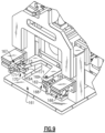
- the float assembly includes links that interconnect the gun to the frame.
- the links are configured to permit the gun to move in a horizontal plane.
- the homing assembly includes a pin that selectively cooperates with a guide to retain the gun in the home position.
- the loading step includes the step of robotically transferring the part to the assembly station with the assembly station in a home position.
- the permitting step includes releasing the assembly station from the home position subsequent to performing the step of robotically transferring the part.
- the feeder retracting step includes overcoming spring biased jaws in the feeder.
- the method includes the step of picking up the part off of a drag conveyor prior to the part loading step.
- the disclosed system provides low-cost automation to weld fasteners, or secure other parts such as pins, clips, or brackets to sheet metal stampings at high speeds.
- the same system can be applied to other assembly processes such as rivets, self-piercing fasteners, mechanical fasteners to a variety of workpieces including those made of plastic.
- the disclosed system is discussed primarily in terms of a welding system and method, it should be understood that other types of securing systems are contemplated.
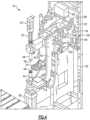
- a welding system 10 is schematically illustrated in Fig. 1 .
- First and second conveyors 12a, 12b feed different parts, such as stampings, into a robot 14 within a welding station 15.
- the robot 14 transfers the parts from the conveyors 12a, 12b to welding machines 16a, 16b.
- One welding machine 16a secures studs supplied by a vibratory feeder bowl 17a
- the other welding machine 16b secures nuts supplied by a vibratory feeder bowl 17b.
- the arrangement shown in Fig. 1 is exemplary only and may be configured differently than illustrated.
- the supplemental actuator would advance the supplemental pin to engage the workpiece W.
- the shape of the pin would be selected to urge the resistance welding gun into the proper position for welding when it engages the workpiece W. Relocation of this function to the supplemental actuator and pin would not affect the ability of the fastener locating pin 50 to provide the function of monitoring and detecting the fastener F.
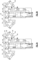
- Fig. 7B is a top view of the resistance welding gun 32 in a position where the guide pins 62 and 64 are no longer engaged or aligned with the homing guides 68 and 70 respectively. This position is achieved when the homing actuator 66 retracts the guide pins 62 and 64 from the homing guides 68 and 70 and force applied on the fastener locating pin 50 urges the resistance welding gun 32 into such an alignment. The difference in position of the resistance welding gun 32 in Figure 7A and Figure 7B is not visible in these figures.
- the spacing and position of the homing guides 68 and 70 is a function of the resistance welding gun 32 and the distance from the center of the homing guides 68 and 70 to the center of the fastener locating pin 50.
- the homing actuator 66 must have a force and travel speed sufficient to realign the guide pins 62 and 64 and homing guides 68 and 70 quickly and without excessive shock.
- Fig. 10 is a perspective view of the drag conveyor 12 with the addition of a number of workpieces W.
- the workpieces W are engaged on number of evenly spaced transfer pins 110 are affixed to conveyor chains 112.
- Three such conveyor chains 112 are supported and driven by a sprocket assembly at each end of the drag conveyor 12.
- the conveyor chains 112 are aligned with spaces provided between adjacent friction bars 116 to permit the travel of the transfer pins 110 and thereby the workpieces W.
- the workpiece W shown in Fig. 10 is used to illustrate the principles of operation and is not representative of the range and size of permissible workpieces W. While not defined in the hardware, a number of zones are illustrated in Fig. 10 to explain the operation of the drag conveyor 12.
- An operator loading zone A is within easy reach of an operator who will manually sort, orient, and place a workpiece W so the selected attribute of the workpiece W, such as a specific hole, engages a transfer pin 110.
- zone A Within zone A, the orientation of the workpiece W is not required to be precise and the number of occupied transfer pins 110, as well as the sequence in which they are loaded is not important.
- the sprocket assembly 114 drives the conveyor chains 112 to advance the transfer pins 110 towards the unloading zone C.
- the conveyor frame 118 shown in Fig. 10 is illustrative only. It can be a freestanding unit as shown or integrated with the frame supporting other components of the welding system 10.
- the number and length of conveyor chains 112 is dependent on the number and spacing of transfer pins 110 required to support the welding system 10 operating requirements.
- the transfer pins 100 may not have a circular cross section and of any length required to engage the workpiece W while it is resting on a surface.
- the length and definition of the illustrated drag conveyor 12 zones is a function of the welding system 10 operating requirements and other factors such as machine guarding, and the duration of friction application required to ensure the workpieces W are consistently oriented.
- the friction bar 116 would commonly be made of sheet or plate steel with a width, length, and thickness suited to the size of the workpiece W. Instead of changing the length of transfer pins 110 to suit different workpieces W, provision can be made to change the spacing between the friction bar 116 and conveyor chain 112.
Landscapes
- Engineering & Computer Science (AREA)
- Mechanical Engineering (AREA)
- Physics & Mathematics (AREA)
- Optics & Photonics (AREA)
- Automatic Assembly (AREA)
- Resistance Welding (AREA)
- Lining Or Joining Of Plastics Or The Like (AREA)
- Pressure Welding/Diffusion-Bonding (AREA)
Claims (15)
- Sicherungssystem, umfassend:einen Roboter (14), der dafür konfiguriert ist, ein Werkstück (W) zu einer Ausgangsposition zu überführen;eine Sicherungsstation schließt Folgendes ein:einen Rahmen (30);eine auf dem Rahmen (30) gehaltene Pistole (32), die Pistole (32) schließt eine ortsfeste Schweißelektrode (48) und eine bewegliche Schweißelektrode (44) ein, wobei die bewegliche Schweißelektrode (44) der ortsfesten Schweißelektrode (48) gegenüberliegt, die Pistole (32) ist dazu geeignet, in einer Sicherungsposition während eines Sicherungsvorgangs eine Komponente an dem Werkstück (W) zu sichern; undeinen Schwebeaufbau (59) die Pistole (32) mit dem Rahmen (30) verbindet, der Schwebeaufbau (59), der dazu geeignet ist, zuzulassen, dass die Pistole (32) relativ zum Rahmen (30) zwischen der Ausgangsposition und der Sicherungsposition gleitet, wobei die ortsfeste Schweißelektrode (48) einen Positionierstift (50) und einen Positionierstiftzylinder (52) umfasst und wobei im Gebrauch, wenn der Positionierstiftzylinder (52) den Befestigungsmittelpositionierstift (50) durch das Werkstück (W) vordrängt, jegliche Fehlausrichtung zwischen dem Befestigungsmittelpositionierstift (50) und einem Loch in dem Werkstück (W) eine Kraft auf einer Seite des Positionierstiftes (50) verursacht, die die Widerstandsschweißpistole (32) dazu drängt, sich in einer Ebene der Schweißnaht in eine nachgiebige Position zu bewegen, in der der Befestigungsmittelpositionierstift (50) in dem Loch in dem Werkstück (W) zentriert und mit dem Befestigungsmittel (F) auf der anderen Seite in Eingriff gebracht wird;einen Zielansteuerungsaufbau (61, 161) eine Zielansteuerungsführung (68, 70), die dazu geeignet ist, die Pistole (32) während des Sicherungsvorgangs aus der Ausgangsposition zu lösen, und ein Zielansteuerungsstellglied (66) einschließt, das, wenn es eingezogen ist, zulässt, dass sich die Widerstandsschweißpistole (32) frei in der Ebene der Schweißnaht bewegt.
- System nach Anspruch 1, wobei die Sicherungsstation eine Schweißstation (15) ist, die einen von dem Rahmen (30) getragenen Beschicker (34) einschließt, der Beschicker, der dafür konfiguriert ist, relativ zur Ausgangsposition zwischen der vorgedrängten und der eingezogenen Position des Beschickers zu gleiten, die Komponente ist in der vorgedrängten Position des Beschickers über der zweiten Elektrode angeordnet.
- System nach Anspruch 2, wobei der Beschicker (34) dafür konfiguriert ist, die Komponente der Pistole (32) bereitzustellen, wobei sich die bewegliche Schweißelektrode (44) in einer vorgedrängten Position der Elektrode befindet und die Komponente ein Befestigungsmittel ist.
- System nach Anspruch 3, wobei die bewegliche Schweißelektrode (44) zwischen einer eingezogenen Position der Elektrode und einer vorgedrängten Position der Elektrode beweglich ist.
- System nach Anspruch 4, wobei die ortsfeste Schweißelektrode (48) einen Stift (46) zum groben Positionieren des Befestigungsmittels einschließt, der zwischen einer vorgedrängten Position des Stifts und einer eingezogenen Position des Stifts beweglich ist, wobei sich die bewegliche Schweißelektrode (44) in der vorgedrängten Position der Elektrode befindet.
- System nach Anspruch 5, wobei der Stift (46) zum groben Positionieren des Befestigungsmittels dafür konfiguriert ist, in eine Komponente einzugreifen, wenn sich der Beschicker (34) in der vorgedrängten Position des Beschickers befindet und sich der Stift (46) zum groben Positionieren des Befestigungsmittels in der vorgedrängten Position des Stifts befindet, und wahlweise
wobei der Beschicker (34) dafür konfiguriert ist, sich von der vorgedrängten Position des Beschickers in die eingezogene Position des Beschickers zu bewegen, wenn die Komponente auf dem Stift (46) geladen ist, wobei das System einen Lösemechanismus umfasst wobei, die Komponente dafür konfiguriert ist, durch den Lösemechanismus gelöst zu werden, wenn er sich in die eingezogene Position des Beschickers bewegt. - System nach Anspruch 6, wobei der Beschicker (34) gegenüberliegende Backen (86, 88) einschließt, die durch Federn (90, 92) in eine die Komponente haltende Position vorgespannt sind, wobei die Backen (86, 88) dafür konfiguriert sind, die Komponente zu lösen und die Federn (90, 92) zu überwinden, wenn sich der Beschicker (34) von der vorgedrängten Position des Beschickers in die eingezogene Position des Beschickers bewegt, und wahlweise
wobei der Beschicker (34) eine Klammer (96) einschließt, die dafür konfiguriert ist, eine zweite Komponente hinter einer ersten Komponente zu halten, die erste Komponente auf dem Stift (46) zum groben Positionieren des Befestigungsmittels geladen ist, die Klammer (96) dafür konfiguriert ist, zyklisch zu laufen und zuzulassen, dass die zweite Komponente zu den Backen (86, 88) zum anschließenden Laden auf den Stift (46) zum groben Positionieren des Befestigungsmittels vorgedrängt wird. - System nach Anspruch 1, wobei der Schwebeaufbau (59) Verbindungsglieder (58, 60) einschließt, die die Pistole (32) mit dem Rahmen (30) verbinden, wobei die Verbindungsglieder (58, 60) dafür konfiguriert sind zuzulassen, dass sich die Pistole (32) in einer horizontalen Ebene bewegt, oderwobei der Zielansteuerungsaufbau (61, 161) einen Stift (62, 162) einschließt, der selektiv mit einer Führung (68, 168) zusammenwirkt, um die Pistole (32) in der Ausgangsposition zu halten, und wahlweisewobei die Führung (161) Arme (169) einschließt, die selektiv in den Stift (168) eingreifen, um die Pistole (32) innerhalb einer horizontalen Ebene zu positionieren.
- System nach Anspruch 1, umfassend ein Steuerungssystem (20), wobei das Steuerungssystem (20) dafür konfiguriert ist, eine Position der beweglichen Schweißelektrode (44) und eines Stifts (46) auszuwerten, um Werkstück- und Betriebsfehlerbedingungen zu identifizieren, zu enthalten und zu sanieren, und wahlweise
wobei das Steuerungssystem (20) einen Plan von Parametern entsprechend einer Anzahl von Aufbaukonfigurationen enthält. - Verfahren zum Herstellen eines Aufbaus unter Verwendung eines Sicherungssystems nach einem der vorhergehenden Ansprüche, wobei das Verfahren die folgenden Schritte umfasst:Laden eines Werkstücks (W) in eine Aufbaustation (10);Zulassen, dass die Aufbaustation (10) in zwei Richtungen relativ zu dem Werkstück (W) schwebt; undSichern einer Komponente an dem Werkstück (W) an der Aufbaustation (10) während des Ausführens des Schritts des Zulassens.
- Verfahren nach Anspruch 10, wobei die Komponente ein Befestigungsmittel (F) ist, die Aufbaustation eine Schweißstation (10) ist und der Sicherungsschritt das Schweißen des Befestigungsmittels (F) an das Werkstück (W) einschließt.
- Verfahren nach Anspruch 10, wobei der Schritt des Ladens den Schritt des Überführens des Werkstücks (W) durch einen Roboter zu der Aufbaustation (10) einschließt, wobei sich die Aufbaustation (10) in einer Ausgangsposition befindet, und der Schritt des Zulassens das Lösen der Aufbaustation aus der Ausgangsposition anschließend an das Ausführen des Schritts des Überführens des Werkstücks (W) durch einen Roboter einschließt.
- Verfahren nach Anspruch 12, umfassend den Schritt des Ladens der Komponente auf die bewegliche Schweißelektrode (44) mit einem Beschicker (34) und des Einziehens des Beschickers (34) anschließend an den Schritt des Ladens der Komponente, wobei der Schritt des Einziehens des Beschickers vor dem Schritt des Zulassens ausgeführt wird.
- Verfahren nach Anspruch 13, aufweisend mindestens eines der Folgenden:den Schritt des Vordrängens der beweglichen Schweißelektrode (44), um während des Schritts des Zulassens das Werkstück (W) in Eingriff zu nehmen; oderwobei die Komponente eine erste Komponente ist, und umfassend den Schritt des Einspannens einer zweiten Komponente in dem Beschicker (34), und des Lösens der ersten Komponente während des Schritts des Einziehens des Beschickers, und des Ausführens des Schritts des Ausspannens der zweiten Komponente, oderwobei der Schritt des Einziehens des Beschickers das Überwinden von durch eine Feder vorgespannten Backen (86, 88) in dem Beschicker (34) einschließt.
- Verfahren nach Anspruch 12, umfassend den Schritt des Aufnehmens des Werkstücks (W) von einem Schleppförderband (12) vor dem Schritt des Ladens des Werkstücks.
Applications Claiming Priority (2)
| Application Number | Priority Date | Filing Date | Title |
|---|---|---|---|
| US201462020064P | 2014-07-02 | 2014-07-02 | |
| PCT/CA2015/050614 WO2016000077A1 (en) | 2014-07-02 | 2015-07-02 | System and method with floating welder for high rate production welding |
Publications (4)
| Publication Number | Publication Date |
|---|---|
| EP3164241A1 EP3164241A1 (de) | 2017-05-10 |
| EP3164241A4 EP3164241A4 (de) | 2018-04-11 |
| EP3164241B1 true EP3164241B1 (de) | 2025-01-15 |
| EP3164241C0 EP3164241C0 (de) | 2025-01-15 |
Family
ID=55018190
Family Applications (2)
| Application Number | Title | Priority Date | Filing Date |
|---|---|---|---|
| EP15814446.9A Active EP3164346B1 (de) | 2014-07-02 | 2015-07-02 | System und verfahren mit widerstandsförderer für hochproduktives schweissen |
| EP15815660.4A Active EP3164241B1 (de) | 2014-07-02 | 2015-07-02 | System und verfahren mit schwebender schweissvorrichtung für hochproduktives schweissen |
Family Applications Before (1)
| Application Number | Title | Priority Date | Filing Date |
|---|---|---|---|
| EP15814446.9A Active EP3164346B1 (de) | 2014-07-02 | 2015-07-02 | System und verfahren mit widerstandsförderer für hochproduktives schweissen |
Country Status (7)
| Country | Link |
|---|---|
| US (4) | US9895775B2 (de) |
| EP (2) | EP3164346B1 (de) |
| CN (4) | CN110883414B (de) |
| BR (2) | BR112017000033B1 (de) |
| CA (2) | CA2932033A1 (de) |
| MX (2) | MX378657B (de) |
| WO (2) | WO2016000076A1 (de) |
Families Citing this family (45)
| Publication number | Priority date | Publication date | Assignee | Title |
|---|---|---|---|---|
| US9666465B2 (en) * | 2013-12-12 | 2017-05-30 | Seagate Technology Llc | Positioning apparatus |
| US10120364B2 (en) * | 2015-03-27 | 2018-11-06 | GM Global Technology Operations LLC | Self-corrective nut running for robotic applications |
| EP3199288B8 (de) | 2016-01-28 | 2024-05-29 | Böllhoff Verbindungstechnik GmbH | Elementzuführeinrichtung eines setz-schweiss-geräts, ein setz-schweiss-gerät sowie ein verbindungsverfahren in form eines mechanisch-thermischen setz-schweiss-prozesses |
| CN106735813B (zh) * | 2016-12-26 | 2020-10-02 | 宁波宏协承汽车部件有限公司 | 一种点焊机底座机构 |
| CN106914693A (zh) * | 2017-03-10 | 2017-07-04 | 清远诺巴特智能设备有限公司 | 一种高度自动调节的焊接抓手 |
| CN107239650A (zh) * | 2017-04-12 | 2017-10-10 | 同济大学 | 混流焊装系统复杂度计算算法及复杂度源识别诊断方法 |
| DE102017004095A1 (de) * | 2017-04-28 | 2018-10-31 | Iwk Verpackungstechnik Gmbh | Tuben-Umsetzvorrichtung in einer Tubenfüllmaschine und Verfahren zu ihrer Steuerung |
| US10807148B2 (en) * | 2017-06-20 | 2020-10-20 | Fca Us Llc | Upset protrusion joining and forging gun therefor |
| JP7116901B2 (ja) * | 2017-08-01 | 2022-08-12 | オムロン株式会社 | ロボット制御装置、ロボット制御方法及びロボット制御プログラム |
| CN107253206B (zh) * | 2017-08-03 | 2023-05-23 | 长春理工大学 | 工业机器人固定电阻点焊钳电极帽铣削与更换系统 |
| CN109896297B (zh) * | 2017-12-08 | 2021-03-16 | 泰科电子(上海)有限公司 | 自动供料系统 |
| MX2020012338A (es) | 2018-06-06 | 2021-01-29 | Doben Ltd | Transportador magnetico de pieza de trabajo para celda de soldadura robotica. |
| CN108857007A (zh) * | 2018-09-10 | 2018-11-23 | 成都众凯汽车零部件制造有限公司 | 一种凹槽工件自动焊接装置 |
| US11654517B2 (en) | 2018-09-11 | 2023-05-23 | Jr Automation Technologies, Llc | Fastener welding apparatus |
| JP7275276B2 (ja) * | 2018-12-13 | 2023-05-17 | ハウメット エアロスペース インコーポレイテッド | リベット分配システムおよびその使用方法 |
| WO2020160675A1 (en) | 2019-02-08 | 2020-08-13 | Miralis Inc. | Robotic systems and methods for assembling furniture |
| CN110412942A (zh) * | 2019-07-17 | 2019-11-05 | 华域汽车车身零件(上海)有限公司 | 一种用于白车身柔性工装切换自动防错系统 |
| CN110421245A (zh) * | 2019-08-22 | 2019-11-08 | 上海兰盈智能科技有限公司 | 多工位快换式凸焊件夹具体安装结构及自动焊接方式 |
| CN110524214B (zh) * | 2019-09-10 | 2023-11-17 | 芜湖全程智能科技有限公司 | 一种汽车ptc水加热器下电极片安装装置及其安装方法 |
| CN110560953B (zh) * | 2019-09-24 | 2024-01-26 | 杭州中久自控系统有限公司 | 储液器自动焊接设备 |
| US20230047883A1 (en) * | 2020-02-04 | 2023-02-16 | Magna Exteriors Inc. | Flexible punch and weld system |
| CN111590308B (zh) * | 2020-05-29 | 2021-10-08 | 成都优博创通信技术有限公司 | 一种加工台 |
| CN111890030B (zh) * | 2020-06-29 | 2022-03-29 | 中山市易恩自动化科技有限公司 | 一种全自动加热件组装设备 |
| CN112122853B (zh) * | 2020-09-24 | 2024-10-01 | 辽宁忠旺特种车辆制造有限公司 | 一种骨架车悬架支撑件总成组焊工装及加工系统、方法 |
| KR102297520B1 (ko) * | 2020-10-12 | 2021-09-02 | (주)삼성텍 | 전기 및 내연기관 자동차용 금속가공품의 이종 너트 용접 자동화 시스템 |
| CN112719547A (zh) * | 2020-12-19 | 2021-04-30 | 河南中车重型装备有限公司 | 一种电阻焊机自动定位焊接平台 |
| CN112719710B (zh) * | 2020-12-29 | 2022-11-01 | 泉州芸台科技有限公司 | 一种自动上料的焊接工作台 |
| CN112850101B (zh) * | 2021-01-22 | 2022-03-29 | 龙光电子集团有限公司 | 一种装配件组装系统 |
| CN113042948B (zh) * | 2021-03-20 | 2022-10-14 | 寰宇东方国际集装箱(宁波)有限公司 | 一种集装箱侧板生产线 |
| US12138772B2 (en) * | 2021-04-30 | 2024-11-12 | Divergent Technologies, Inc. | Mobile parts table |
| DE102021120555A1 (de) * | 2021-08-06 | 2023-02-09 | Eckold Gmbh & Co. Kg | Fügekopf zur Befestigung eines Befestigungselementes auf der Oberfläche eines Bauteils |
| CN113562435B (zh) * | 2021-09-24 | 2021-12-07 | 四川大学 | 一种药用瓶塞高效整理机 |
| CN113579623B (zh) * | 2021-09-26 | 2021-11-30 | 江苏力腾机械有限公司 | 一种五金附件的快速定位焊接设备 |
| CN113909721B (zh) * | 2021-09-29 | 2022-12-02 | 长沙中创海通智能科技有限公司 | 一种用于建筑模板焊接封板的装置 |
| US20230135381A1 (en) * | 2021-11-01 | 2023-05-04 | Legacy Industries | Floating system and method for a tool |
| CN114193055B (zh) * | 2021-12-17 | 2023-05-05 | 北京石油化工学院 | 预制水泥钢筋多枪自动焊接装置及其焊接系统 |
| CN115156683B (zh) * | 2022-08-22 | 2024-04-09 | 广州松兴电气股份有限公司 | 一种用于白车身凸焊生产线的自动送料系统 |
| US12521787B2 (en) | 2022-11-15 | 2026-01-13 | Doben Limited | Self-piercing clinch fastener installation press |
| US12290890B2 (en) | 2023-02-16 | 2025-05-06 | Doben Limited | Automated floating insertion tool for push-in fasteners |
| CN116475640B (zh) * | 2023-05-19 | 2024-01-05 | 广州中益机械有限公司 | 一种汽车部件自动化焊接机器人的上件装置 |
| CN116713580A (zh) * | 2023-06-01 | 2023-09-08 | 上海骏腾发智能设备有限公司 | 双头螺母焊接设备 |
| CN117066631B (zh) * | 2023-10-13 | 2024-01-05 | 湖南凌特科技有限公司 | 一种灯珠连续组装设备 |
| CN117463937B (zh) * | 2023-12-28 | 2024-04-05 | 山东固而美金属制品有限公司 | 一种自动压铆系统 |
| CN117697664A (zh) * | 2024-01-02 | 2024-03-15 | 重庆长安汽车股份有限公司 | 一种锁止装置及定位夹具 |
| US12234853B1 (en) | 2024-07-19 | 2025-02-25 | Doben Limited | Nut feeder and installation machine |
Citations (5)
| Publication number | Priority date | Publication date | Assignee | Title |
|---|---|---|---|---|
| JPS5953275A (ja) * | 1982-09-22 | 1984-03-27 | Nissan Motor Co Ltd | 車両部品の自動組付方法およびその装置 |
| JPH0924474A (ja) * | 1995-07-11 | 1997-01-28 | Nissan Motor Co Ltd | スポット溶接装置 |
| US6720517B2 (en) * | 2001-07-23 | 2004-04-13 | Sumitomo Wiring Systems, Ltd. | Resistance welding head and resistance welding apparatus and method using the head |
| JP2007181848A (ja) * | 2006-01-05 | 2007-07-19 | Shiroyama Kogyo Kk | 接合装置 |
| CN102873448A (zh) * | 2011-07-12 | 2013-01-16 | 上海梅达焊接设备有限公司 | 一种用于点焊机上的自适应浮动加压装置 |
Family Cites Families (63)
| Publication number | Priority date | Publication date | Assignee | Title |
|---|---|---|---|---|
| US2685018A (en) | 1951-06-29 | 1954-07-27 | Gen Motors Corp | Automatic nut loading machine |
| US2843166A (en) | 1955-07-25 | 1958-07-15 | Gen Motors Corp | Stud transfer and holding means for a stud driving tool |
| US2905803A (en) | 1958-01-13 | 1959-09-22 | Gen Motors Corp | Nut loading and welding machine |
| US3233752A (en) | 1964-06-29 | 1966-02-08 | Western Electric Co | Automatic positioning and orienting apparatus |
| US3415350A (en) * | 1966-10-24 | 1968-12-10 | Fmc Corp | Article orienting apparatus |
| JPS5413073B2 (de) * | 1974-03-28 | 1979-05-28 | ||
| US4020316A (en) * | 1975-08-22 | 1977-04-26 | Fastener Industries Inc. | Method and apparatus for positioning nuts to be welded to a base |
| NL7705670A (en) * | 1977-05-24 | 1978-11-28 | Iwema Techniek B V | Conveyor moving crates along treatment stations - rotates crates through 90 degrees by stop in path between stations |
| US4215262A (en) | 1978-03-06 | 1980-07-29 | Conceptual Engineering | Automatic percussion welding apparatus with stud feed |
| CA1071566A (en) * | 1978-03-08 | 1980-02-12 | John W. Hoehn | Apparatus for orienting objects |
| JPS5656396A (en) | 1979-10-12 | 1981-05-18 | Hiroshi Makino | Robot for assembly |
| FR2557537B1 (fr) * | 1984-01-03 | 1986-09-19 | Socomo La Chatelaine | Appareillage pour la manutention de sachets de produits alimentaires, notamment de boissons, en vue de leur emballage apres pasteurisation |
| US4678073A (en) * | 1985-04-04 | 1987-07-07 | American Telephone And Telegraph Company, At&T Technologies, Inc. | Apparatus and methods for handling bulk arrays of articles |
| JPS6231616A (ja) * | 1985-07-30 | 1987-02-10 | Nichiden Mach Ltd | 棒状ワ−ク搬送方法 |
| JPS62286683A (ja) * | 1986-06-05 | 1987-12-12 | Toyota Motor Corp | プロジエクシヨン溶接装置 |
| GB2192572B (en) | 1986-07-17 | 1990-04-04 | Metal Box Plc | Method and apparatus for orientating can ends |
| US4789768A (en) | 1986-12-09 | 1988-12-06 | Toyota Jidosha Kabushiki Kaisha | Projection welder |
| JPS6444392A (en) * | 1987-08-10 | 1989-02-16 | Honda Motor Co Ltd | Assembly equipment for parts for lower section of car |
| US4929146A (en) | 1987-11-13 | 1990-05-29 | U.S. Philips Corporation | Manipulator |
| JPH0622553Y2 (ja) * | 1989-12-19 | 1994-06-15 | トヨタ自動車株式会社 | 溶接部品の自動供給装置 |
| JP2509103B2 (ja) * | 1991-02-23 | 1996-06-19 | 好高 青山 | 部品供給装置 |
| DE4142824C2 (de) | 1991-12-23 | 2000-06-29 | Windmoeller & Hoelscher | Vorrichtung zum Drehen von flachliegend voranbewegten Werkstücken |
| JPH0677978U (ja) | 1992-04-21 | 1994-11-01 | 株式会社三五 | 抵抗溶接機におけるナット心ずれ検出装置 |
| JPH06156721A (ja) * | 1992-11-19 | 1994-06-03 | Fuji Electric Co Ltd | 板材の旋回装置 |
| KR0151438B1 (ko) * | 1992-12-04 | 1998-10-15 | 긴바라 요시로 | 자동 조립 장치 |
| JPH06183542A (ja) * | 1992-12-15 | 1994-07-05 | Kao Corp | ボトル円周方向の位置合わせ方法およびその装置 |
| JPH0712546B2 (ja) | 1993-02-25 | 1995-02-15 | 矢島技研株式会社 | 抵抗溶接機 |
| FR2716874B1 (fr) | 1994-03-03 | 1996-06-21 | Materiel Arboriculture | Dispositif de convoyage de produits, notamment de fruits, adapté pour effectuer un triage desdits produits en fonction de critères de sélection prédéterminés. |
| JP3392210B2 (ja) * | 1994-04-18 | 2003-03-31 | 富士写真フイルム株式会社 | 部品整列装置及びこれを用いた部品組立装置 |
| US5530218A (en) * | 1994-05-30 | 1996-06-25 | Amada Metrecs Company, Limited | Spot welding apparatus |
| JP2807725B2 (ja) * | 1994-05-30 | 1998-10-08 | 株式会社アマダメトレックス | スポット溶接機の電極保持装置 |
| GB9502930D0 (en) * | 1995-02-15 | 1995-04-05 | Starpoint Electrics Ltd | Vending machine |
| JP3094151B2 (ja) | 1996-05-08 | 2000-10-03 | 矢島技研株式会社 | 抵抗溶接機 |
| US6163004A (en) | 1996-08-10 | 2000-12-19 | Yoshitaka Aoyama | Method of welding projection nut and apparatus therefor |
| NL1008841C2 (nl) | 1998-04-08 | 1999-10-11 | Tno | Oriëntatiemechanisme. |
| US6283272B1 (en) * | 1998-12-14 | 2001-09-04 | Texas Instruments Incorporated | Automatic tube orientation apparatus |
| JP2000317644A (ja) * | 1999-05-08 | 2000-11-21 | Yoshitaka Aoyama | 複式溶接機への部品供給方法 |
| US6481560B2 (en) * | 2000-06-08 | 2002-11-19 | Christopher L. Kearney | Robotic feeding system |
| CN1262385C (zh) | 2000-12-13 | 2006-07-05 | 株式会社Smk | 螺母或螺栓的焊接装置 |
| EP1400301A4 (de) | 2001-06-28 | 2007-01-24 | Yoshitaka Aoyama | Verfahren und vorrichtung zum schweissen eines vorspringenden bolzens |
| US6576859B2 (en) * | 2001-07-10 | 2003-06-10 | Doben Limited | Resistance welding fastener electrode |
| US7564005B2 (en) * | 2001-07-10 | 2009-07-21 | Doben Limited | Resistance welding fastener electrode and monitor and method of using same |
| US6965383B2 (en) | 2001-12-11 | 2005-11-15 | Lecroy Corporation | Scaling persistence data with interpolation |
| EP1346792A1 (de) * | 2002-03-21 | 2003-09-24 | H.A. Schlatter Ag | Schweiss- bzw. Fügeeinheit |
| JP3684480B2 (ja) * | 2002-05-08 | 2005-08-17 | 矢島技研株式会社 | 部品供給装置 |
| DE102004057814B4 (de) * | 2004-11-30 | 2014-02-06 | Daimler Ag | Verfahren zum Steuern der Stellung von Werkstück und Werkzeug mit einem Roboter in einer Bearbeitungsmaschine |
| DE102005044367A1 (de) * | 2005-09-09 | 2007-03-15 | Newfrey Llc, Newark | Fügesystemkopf, Fügesystem und Verfahren zum Zuführen und Fügen von Elementen |
| JP4186167B2 (ja) * | 2005-10-24 | 2008-11-26 | 好高 青山 | 軸状部品の溶接装置 |
| CN100363141C (zh) * | 2005-12-09 | 2008-01-23 | 新兴铸管股份有限公司 | 钢格板压焊机 |
| WO2007074561A1 (ja) | 2005-12-27 | 2007-07-05 | Yajima Giken, Inc. | ナット自動供給装置 |
| EP2027045A2 (de) * | 2006-06-15 | 2009-02-25 | Laitram, L.L.C. | Förderband zur drehung von gegenständen |
| US8338738B2 (en) | 2007-03-02 | 2012-12-25 | Yoshitaka Aoyama | Method of welding projection bolt and welding apparatus |
| ES2391424T3 (es) * | 2007-09-11 | 2012-11-26 | Fps Food Processing Systems B.V. | Aparato para tratar productos alargados tales como pepinos |
| US7819234B2 (en) * | 2008-10-31 | 2010-10-26 | Herzog Kenneth J | Bottle orienting device |
| US8294064B1 (en) * | 2010-03-18 | 2012-10-23 | Honda Motor Co., Ltd. | Floating electrode assembly and automated system and method for welding projection weld nuts |
| JP4590021B1 (ja) * | 2010-05-14 | 2010-12-01 | 昭和電工株式会社 | 搬送システム、搬送装置、物品、および検査システム |
| CH703561A1 (de) | 2010-08-06 | 2012-02-15 | Ferag Ag | Vorrichtung zur Ausrichtung eines flächigen Produktes. |
| DE102011013390A1 (de) * | 2011-03-09 | 2011-11-10 | Daimler Ag | Verfahren zum Bearbeiten zumindest eines Werkstücks |
| FR2976571B1 (fr) * | 2011-06-17 | 2014-04-04 | Arjowiggins Security | Installation d'orientation de bouteilles |
| DE202011108531U1 (de) * | 2011-12-01 | 2012-01-17 | Tünkers Iberica S.L. | Stauförderer |
| US8973733B2 (en) * | 2012-01-04 | 2015-03-10 | Douglas Machine Inc. | Article orienter and attendant orientation operations |
| JP5852742B2 (ja) * | 2012-08-24 | 2016-02-03 | Ykk株式会社 | ボタン又はボタン取付具の搬送装置 |
| JP7012546B2 (ja) | 2018-02-01 | 2022-02-14 | サンコール株式会社 | トルクリミッタ |
-
2015
- 2015-07-02 WO PCT/CA2015/050613 patent/WO2016000076A1/en not_active Ceased
- 2015-07-02 CN CN201911254635.3A patent/CN110883414B/zh active Active
- 2015-07-02 US US15/120,930 patent/US9895775B2/en active Active
- 2015-07-02 BR BR112017000033-4A patent/BR112017000033B1/pt active IP Right Grant
- 2015-07-02 CA CA2932033A patent/CA2932033A1/en not_active Abandoned
- 2015-07-02 MX MX2016007919A patent/MX378657B/es unknown
- 2015-07-02 EP EP15814446.9A patent/EP3164346B1/de active Active
- 2015-07-02 CN CN201910127697.1A patent/CN109650012A/zh active Pending
- 2015-07-02 WO PCT/CA2015/050614 patent/WO2016000077A1/en not_active Ceased
- 2015-07-02 EP EP15815660.4A patent/EP3164241B1/de active Active
- 2015-07-02 CN CN201580004669.0A patent/CN105916624B/zh active Active
- 2015-07-02 US US15/120,901 patent/US10471549B2/en active Active
- 2015-07-02 CA CA2933577A patent/CA2933577C/en active Active
- 2015-07-02 CN CN201580004007.3A patent/CN106687398B/zh active Active
- 2015-07-02 MX MX2016007918A patent/MX2016007918A/es unknown
- 2015-07-02 BR BR112017000032-6A patent/BR112017000032B1/pt active IP Right Grant
-
2019
- 2019-10-31 US US16/670,136 patent/US11883908B2/en active Active
-
2023
- 2023-12-18 US US18/543,383 patent/US12472589B2/en active Active
Patent Citations (5)
| Publication number | Priority date | Publication date | Assignee | Title |
|---|---|---|---|---|
| JPS5953275A (ja) * | 1982-09-22 | 1984-03-27 | Nissan Motor Co Ltd | 車両部品の自動組付方法およびその装置 |
| JPH0924474A (ja) * | 1995-07-11 | 1997-01-28 | Nissan Motor Co Ltd | スポット溶接装置 |
| US6720517B2 (en) * | 2001-07-23 | 2004-04-13 | Sumitomo Wiring Systems, Ltd. | Resistance welding head and resistance welding apparatus and method using the head |
| JP2007181848A (ja) * | 2006-01-05 | 2007-07-19 | Shiroyama Kogyo Kk | 接合装置 |
| CN102873448A (zh) * | 2011-07-12 | 2013-01-16 | 上海梅达焊接设备有限公司 | 一种用于点焊机上的自适应浮动加压装置 |
Also Published As
Similar Documents
| Publication | Publication Date | Title |
|---|---|---|
| US12472589B2 (en) | System and method with floating welder for high rate production welding | |
| US10207879B2 (en) | Method and apparatus for honing a workpiece | |
| US11590602B2 (en) | Apparatus for replacing welding tip of welder and apparatus for supplying same | |
| CN110625239A (zh) | 机器人自动凸焊工艺方法 | |
| KR910008198B1 (ko) | 부품 공급장치 | |
| US20140223712A1 (en) | Fastener driving device | |
| CN116060941B (zh) | 弹簧圈装配机 | |
| KR102827288B1 (ko) | 다형상의 피가공물 용접 및 검사 공정 자동화 시스템 | |
| CN118951712A (zh) | 工件自动化组装系统 | |
| KR101555336B1 (ko) | 차량용 부품 배출 장치 | |
| EP3894125B1 (de) | System zum nachladen von nietverbindungen und verwendungsverfahren dafür | |
| US20230173604A1 (en) | Automated fastener feeder and securing system | |
| CN114212487A (zh) | 一种门板锁扣焊接系统 | |
| KR102103717B1 (ko) | 도어트림의 파스너 조립장치 | |
| CN115026622A (zh) | 一种用于复杂零件的通用型自动化加工系统 | |
| JPH0523764A (ja) | 板材の結合装置 |
Legal Events
| Date | Code | Title | Description |
|---|---|---|---|
| STAA | Information on the status of an ep patent application or granted ep patent |
Free format text: STATUS: THE INTERNATIONAL PUBLICATION HAS BEEN MADE |
|
| PUAI | Public reference made under article 153(3) epc to a published international application that has entered the european phase |
Free format text: ORIGINAL CODE: 0009012 |
|
| STAA | Information on the status of an ep patent application or granted ep patent |
Free format text: STATUS: REQUEST FOR EXAMINATION WAS MADE |
|
| 17P | Request for examination filed |
Effective date: 20160525 |
|
| AK | Designated contracting states |
Kind code of ref document: A1 Designated state(s): AL AT BE BG CH CY CZ DE DK EE ES FI FR GB GR HR HU IE IS IT LI LT LU LV MC MK MT NL NO PL PT RO RS SE SI SK SM TR |
|
| AX | Request for extension of the european patent |
Extension state: BA ME |
|
| DAV | Request for validation of the european patent (deleted) | ||
| DAX | Request for extension of the european patent (deleted) | ||
| A4 | Supplementary search report drawn up and despatched |
Effective date: 20180309 |
|
| RIC1 | Information provided on ipc code assigned before grant |
Ipc: B23K 37/047 20060101ALI20180306BHEP Ipc: B23K 11/00 20060101AFI20180306BHEP |
|
| STAA | Information on the status of an ep patent application or granted ep patent |
Free format text: STATUS: EXAMINATION IS IN PROGRESS |
|
| 17Q | First examination report despatched |
Effective date: 20200812 |
|
| REG | Reference to a national code |
Ref country code: DE Ref legal event code: R079 Free format text: PREVIOUS MAIN CLASS: B23K0011300000 Ipc: B23K0011110000 Ref country code: DE Ref legal event code: R079 Ref document number: 602015090865 Country of ref document: DE Free format text: PREVIOUS MAIN CLASS: B23K0011300000 Ipc: B23K0011110000 |
|
| RIC1 | Information provided on ipc code assigned before grant |
Ipc: B23K 37/047 20060101ALI20240408BHEP Ipc: B23K 11/00 20060101ALI20240408BHEP Ipc: B65G 47/244 20060101ALI20240408BHEP Ipc: B65G 19/02 20060101ALI20240408BHEP Ipc: B23P 19/00 20060101ALI20240408BHEP Ipc: B21J 15/32 20060101ALI20240408BHEP Ipc: B21J 15/10 20060101ALI20240408BHEP Ipc: B65G 47/24 20060101ALI20240408BHEP Ipc: B23P 19/04 20060101ALI20240408BHEP Ipc: B23K 37/04 20060101ALI20240408BHEP Ipc: B23K 11/11 20060101AFI20240408BHEP |
|
| GRAP | Despatch of communication of intention to grant a patent |
Free format text: ORIGINAL CODE: EPIDOSNIGR1 |
|
| STAA | Information on the status of an ep patent application or granted ep patent |
Free format text: STATUS: GRANT OF PATENT IS INTENDED |
|
| INTG | Intention to grant announced |
Effective date: 20240523 |
|
| GRAJ | Information related to disapproval of communication of intention to grant by the applicant or resumption of examination proceedings by the epo deleted |
Free format text: ORIGINAL CODE: EPIDOSDIGR1 |
|
| STAA | Information on the status of an ep patent application or granted ep patent |
Free format text: STATUS: EXAMINATION IS IN PROGRESS |
|
| INTC | Intention to grant announced (deleted) | ||
| GRAP | Despatch of communication of intention to grant a patent |
Free format text: ORIGINAL CODE: EPIDOSNIGR1 |
|
| STAA | Information on the status of an ep patent application or granted ep patent |
Free format text: STATUS: GRANT OF PATENT IS INTENDED |
|
| INTG | Intention to grant announced |
Effective date: 20240821 |
|
| GRAS | Grant fee paid |
Free format text: ORIGINAL CODE: EPIDOSNIGR3 |
|
| GRAA | (expected) grant |
Free format text: ORIGINAL CODE: 0009210 |
|
| STAA | Information on the status of an ep patent application or granted ep patent |
Free format text: STATUS: THE PATENT HAS BEEN GRANTED |
|
| AK | Designated contracting states |
Kind code of ref document: B1 Designated state(s): AL AT BE BG CH CY CZ DE DK EE ES FI FR GB GR HR HU IE IS IT LI LT LU LV MC MK MT NL NO PL PT RO RS SE SI SK SM TR |
|
| REG | Reference to a national code |
Ref country code: CH Ref legal event code: EP Ref country code: GB Ref legal event code: FG4D |
|
| REG | Reference to a national code |
Ref country code: IE Ref legal event code: FG4D |
|
| REG | Reference to a national code |
Ref country code: DE Ref legal event code: R096 Ref document number: 602015090865 Country of ref document: DE |
|
| U01 | Request for unitary effect filed |
Effective date: 20250206 |
|
| U07 | Unitary effect registered |
Designated state(s): AT BE BG DE DK EE FI FR IT LT LU LV MT NL PT RO SE SI Effective date: 20250213 |
|
| PG25 | Lapsed in a contracting state [announced via postgrant information from national office to epo] |
Ref country code: RS Free format text: LAPSE BECAUSE OF FAILURE TO SUBMIT A TRANSLATION OF THE DESCRIPTION OR TO PAY THE FEE WITHIN THE PRESCRIBED TIME-LIMIT Effective date: 20250415 |
|
| PG25 | Lapsed in a contracting state [announced via postgrant information from national office to epo] |
Ref country code: PL Free format text: LAPSE BECAUSE OF FAILURE TO SUBMIT A TRANSLATION OF THE DESCRIPTION OR TO PAY THE FEE WITHIN THE PRESCRIBED TIME-LIMIT Effective date: 20250115 |
|
| PG25 | Lapsed in a contracting state [announced via postgrant information from national office to epo] |
Ref country code: ES Free format text: LAPSE BECAUSE OF FAILURE TO SUBMIT A TRANSLATION OF THE DESCRIPTION OR TO PAY THE FEE WITHIN THE PRESCRIBED TIME-LIMIT Effective date: 20250115 |
|
| PG25 | Lapsed in a contracting state [announced via postgrant information from national office to epo] |
Ref country code: IS Free format text: LAPSE BECAUSE OF FAILURE TO SUBMIT A TRANSLATION OF THE DESCRIPTION OR TO PAY THE FEE WITHIN THE PRESCRIBED TIME-LIMIT Effective date: 20250515 Ref country code: NO Free format text: LAPSE BECAUSE OF FAILURE TO SUBMIT A TRANSLATION OF THE DESCRIPTION OR TO PAY THE FEE WITHIN THE PRESCRIBED TIME-LIMIT Effective date: 20250415 |
|
| PG25 | Lapsed in a contracting state [announced via postgrant information from national office to epo] |
Ref country code: HR Free format text: LAPSE BECAUSE OF FAILURE TO SUBMIT A TRANSLATION OF THE DESCRIPTION OR TO PAY THE FEE WITHIN THE PRESCRIBED TIME-LIMIT Effective date: 20250115 |
|
| PG25 | Lapsed in a contracting state [announced via postgrant information from national office to epo] |
Ref country code: GR Free format text: LAPSE BECAUSE OF FAILURE TO SUBMIT A TRANSLATION OF THE DESCRIPTION OR TO PAY THE FEE WITHIN THE PRESCRIBED TIME-LIMIT Effective date: 20250416 |
|
| U20 | Renewal fee for the european patent with unitary effect paid |
Year of fee payment: 11 Effective date: 20250621 |
|
| PG25 | Lapsed in a contracting state [announced via postgrant information from national office to epo] |
Ref country code: SM Free format text: LAPSE BECAUSE OF FAILURE TO SUBMIT A TRANSLATION OF THE DESCRIPTION OR TO PAY THE FEE WITHIN THE PRESCRIBED TIME-LIMIT Effective date: 20250115 |
|
| PG25 | Lapsed in a contracting state [announced via postgrant information from national office to epo] |
Ref country code: CZ Free format text: LAPSE BECAUSE OF FAILURE TO SUBMIT A TRANSLATION OF THE DESCRIPTION OR TO PAY THE FEE WITHIN THE PRESCRIBED TIME-LIMIT Effective date: 20250115 |
|
| PG25 | Lapsed in a contracting state [announced via postgrant information from national office to epo] |
Ref country code: SK Free format text: LAPSE BECAUSE OF FAILURE TO SUBMIT A TRANSLATION OF THE DESCRIPTION OR TO PAY THE FEE WITHIN THE PRESCRIBED TIME-LIMIT Effective date: 20250115 |
|
| PLBE | No opposition filed within time limit |
Free format text: ORIGINAL CODE: 0009261 |
|
| STAA | Information on the status of an ep patent application or granted ep patent |
Free format text: STATUS: NO OPPOSITION FILED WITHIN TIME LIMIT |
|
| REG | Reference to a national code |
Ref country code: CH Ref legal event code: L10 Free format text: ST27 STATUS EVENT CODE: U-0-0-L10-L00 (AS PROVIDED BY THE NATIONAL OFFICE) Effective date: 20251126 |
|
| 26N | No opposition filed |
Effective date: 20251016 |
|
| REG | Reference to a national code |
Ref country code: CH Ref legal event code: H13 Free format text: ST27 STATUS EVENT CODE: U-0-0-H10-H13 (AS PROVIDED BY THE NATIONAL OFFICE) Effective date: 20260224 |
|
| GBPC | Gb: european patent ceased through non-payment of renewal fee |
Effective date: 20250702 |
|
| PG25 | Lapsed in a contracting state [announced via postgrant information from national office to epo] |
Ref country code: GB Free format text: LAPSE BECAUSE OF NON-PAYMENT OF DUE FEES Effective date: 20250702 |
|
| PG25 | Lapsed in a contracting state [announced via postgrant information from national office to epo] |
Ref country code: CH Free format text: LAPSE BECAUSE OF NON-PAYMENT OF DUE FEES Effective date: 20250731 |
|
| U1N | Appointed representative for the unitary patent procedure changed after the registration of the unitary effect |
Representative=s name: MARKS & CLERK LLP; GB |