EP2927695A1 - Probenverteilungssystem und Laborautomatisierungssystem - Google Patents
Probenverteilungssystem und Laborautomatisierungssystem Download PDFInfo
- Publication number
- EP2927695A1 EP2927695A1 EP14162952.7A EP14162952A EP2927695A1 EP 2927695 A1 EP2927695 A1 EP 2927695A1 EP 14162952 A EP14162952 A EP 14162952A EP 2927695 A1 EP2927695 A1 EP 2927695A1
- Authority
- EP
- European Patent Office
- Prior art keywords
- sample
- transport surface
- distribution system
- contamination
- detection device
- Prior art date
- Legal status (The legal status is an assumption and is not a legal conclusion. Google has not performed a legal analysis and makes no representation as to the accuracy of the status listed.)
- Granted
Links
Images
Classifications
-
- G—PHYSICS
- G01—MEASURING; TESTING
- G01N—INVESTIGATING OR ANALYSING MATERIALS BY DETERMINING THEIR CHEMICAL OR PHYSICAL PROPERTIES
- G01N35/00—Automatic analysis not limited to methods or materials provided for in any single one of groups G01N1/00 - G01N33/00; Handling materials therefor
- G01N35/10—Devices for transferring samples or any liquids to, in, or from, the analysis apparatus, e.g. suction devices, injection devices
- G01N35/1081—Devices for transferring samples or any liquids to, in, or from, the analysis apparatus, e.g. suction devices, injection devices characterised by the means for relatively moving the transfer device and the containers in an horizontal plane
-
- G—PHYSICS
- G01—MEASURING; TESTING
- G01N—INVESTIGATING OR ANALYSING MATERIALS BY DETERMINING THEIR CHEMICAL OR PHYSICAL PROPERTIES
- G01N35/00—Automatic analysis not limited to methods or materials provided for in any single one of groups G01N1/00 - G01N33/00; Handling materials therefor
- G01N35/02—Automatic analysis not limited to methods or materials provided for in any single one of groups G01N1/00 - G01N33/00; Handling materials therefor using a plurality of sample containers moved by a conveyor system past one or more treatment or analysis stations
-
- G—PHYSICS
- G01—MEASURING; TESTING
- G01N—INVESTIGATING OR ANALYSING MATERIALS BY DETERMINING THEIR CHEMICAL OR PHYSICAL PROPERTIES
- G01N27/00—Investigating or analysing materials by the use of electric, electrochemical, or magnetic means
- G01N27/02—Investigating or analysing materials by the use of electric, electrochemical, or magnetic means by investigating impedance
- G01N27/22—Investigating or analysing materials by the use of electric, electrochemical, or magnetic means by investigating impedance by investigating capacitance
- G01N27/24—Investigating the presence of flaws
-
- G—PHYSICS
- G01—MEASURING; TESTING
- G01N—INVESTIGATING OR ANALYSING MATERIALS BY DETERMINING THEIR CHEMICAL OR PHYSICAL PROPERTIES
- G01N35/00—Automatic analysis not limited to methods or materials provided for in any single one of groups G01N1/00 - G01N33/00; Handling materials therefor
- G01N2035/00178—Special arrangements of analysers
- G01N2035/00277—Special precautions to avoid contamination (e.g. enclosures, glove- boxes, sealed sample carriers, disposal of contaminated material)
-
- G—PHYSICS
- G01—MEASURING; TESTING
- G01N—INVESTIGATING OR ANALYSING MATERIALS BY DETERMINING THEIR CHEMICAL OR PHYSICAL PROPERTIES
- G01N35/00—Automatic analysis not limited to methods or materials provided for in any single one of groups G01N1/00 - G01N33/00; Handling materials therefor
- G01N35/02—Automatic analysis not limited to methods or materials provided for in any single one of groups G01N1/00 - G01N33/00; Handling materials therefor using a plurality of sample containers moved by a conveyor system past one or more treatment or analysis stations
- G01N35/04—Details of the conveyor system
- G01N2035/0401—Sample carriers, cuvettes or reaction vessels
- G01N2035/0406—Individual bottles or tubes
-
- G—PHYSICS
- G01—MEASURING; TESTING
- G01N—INVESTIGATING OR ANALYSING MATERIALS BY DETERMINING THEIR CHEMICAL OR PHYSICAL PROPERTIES
- G01N35/00—Automatic analysis not limited to methods or materials provided for in any single one of groups G01N1/00 - G01N33/00; Handling materials therefor
- G01N35/02—Automatic analysis not limited to methods or materials provided for in any single one of groups G01N1/00 - G01N33/00; Handling materials therefor using a plurality of sample containers moved by a conveyor system past one or more treatment or analysis stations
- G01N35/04—Details of the conveyor system
- G01N2035/0401—Sample carriers, cuvettes or reaction vessels
- G01N2035/0429—Sample carriers adapted for special purposes
- G01N2035/0432—Sample carriers adapted for special purposes integrated with measuring devices
-
- G—PHYSICS
- G01—MEASURING; TESTING
- G01N—INVESTIGATING OR ANALYSING MATERIALS BY DETERMINING THEIR CHEMICAL OR PHYSICAL PROPERTIES
- G01N35/00—Automatic analysis not limited to methods or materials provided for in any single one of groups G01N1/00 - G01N33/00; Handling materials therefor
- G01N35/02—Automatic analysis not limited to methods or materials provided for in any single one of groups G01N1/00 - G01N33/00; Handling materials therefor using a plurality of sample containers moved by a conveyor system past one or more treatment or analysis stations
- G01N35/04—Details of the conveyor system
- G01N2035/0401—Sample carriers, cuvettes or reaction vessels
- G01N2035/0437—Cleaning cuvettes or reaction vessels
-
- G—PHYSICS
- G01—MEASURING; TESTING
- G01N—INVESTIGATING OR ANALYSING MATERIALS BY DETERMINING THEIR CHEMICAL OR PHYSICAL PROPERTIES
- G01N35/00—Automatic analysis not limited to methods or materials provided for in any single one of groups G01N1/00 - G01N33/00; Handling materials therefor
- G01N35/02—Automatic analysis not limited to methods or materials provided for in any single one of groups G01N1/00 - G01N33/00; Handling materials therefor using a plurality of sample containers moved by a conveyor system past one or more treatment or analysis stations
- G01N35/04—Details of the conveyor system
- G01N2035/0474—Details of actuating means for conveyors or pipettes
- G01N2035/0477—Magnetic
Definitions
- the invention relates to a sample distribution system with a number of sample carriers, which are designed to receive one or more sample containers, and a laboratory automation system with such a sample distribution system.
- the sample distribution system is intended to transport samples in sample containers to a plurality of different stations of the laboratory automation system.
- the document WO 2013/064656 A1 shows a sample distribution system with a number of sample carriers, which are adapted to receive a sample container, for example in the form of a sample tube.
- the sample containers contain samples to be analyzed, for example blood samples.
- the sample distribution system further comprises a transport surface adapted to support the sample carriers. By means of electromagnetic actuators, the sample carriers can be moved over the transport surface.
- an impurity on the transport surface can be detected, so that it can be reacted to in a suitable manner.
- the contaminant detection device may be configured to recognize parameters such as location, extent, type, area, thickness, and / or other property of the contaminant. Depending on this, for example, appropriate measures can be initiated in an adapted manner.
- the sample carriers are moved by means of electromagnetic actuators arranged under the transport surface, in particular electromagnets.
- the sample carrier are self-propelled.
- wireless communication may be used to obtain driving commands.
- the sample carriers can each have an electric motor and suitable control means in order to move independently over the transport surface.
- the contamination detection device has a number of sensor fields distributed on or over the transport surface.
- the sensor fields can also be distributed under the transport surface.
- the sensor fields can be evenly distributed over the (on / under / in) transport surface. By means of the sensor fields can be detected, at which place on the transport surface contamination is present.
- a respective sample carrier has a contamination sensor, wherein the respective contamination sensors are part of the contamination detection device.
- This may be provided on the transport surface alternatively or in addition to components of the contamination detection device.
- an impurity sensor can already issue a warning signal and trigger appropriate measures if contamination has so far only arrived on the sample carrier, but not yet on the transport surface. By appropriate measures, for example stopping the sample carrier, further contamination can be prevented.
- the contamination detection device has a capacitive touch-sensitive surface.
- a capacitive touch-sensitive surface is understood to mean a surface whose effective capacity changes as a function of a touch or contamination.
- the capacitive surface can be designed such that a position or a location of a touch or contamination can be determined. By means of the capacitive touch-sensitive surface capacitance-changing impurities can be reliably detected.
- the touch-sensitive surface may in particular be arranged on or under the transport surface. It can be subdivided into individual fields in order to enable a determination of the position of the contamination.
- the contamination detection device comprises a first and a second (capacitor) plate, which are each electrically conductive or are coated electrically conductive. This allows easy and reliable detection a capacity change due to contamination.
- a combination of two plates can be provided both on the transport surface and on a sample carrier.
- the controller is in signal communication with the contaminant detection device, wherein the controller is configured to control movement of the sample carriers in response to a detected contaminant. This can be reacted in a suitable manner to a detected contamination. If the contamination detection device is formed in a sample carrier, for example, a radio link can be provided.
- the contamination detection device may be designed to determine a position of an impurity on the transport surface, wherein the control device is designed to determine the movement path of a respective sample carrier such that it does not extend beyond the position of the contaminant. This can be effectively counteracted a distribution of contamination and cross contamination.
- the contaminant detection apparatus may also be configured to determine parameters such as location, extent, type, area, thickness and / or other characteristics of an impurity, which controller may also utilize such characteristics in response to the contaminant to motion control the sample carriers on the transport surface ,
- an exclusion surface such as a circle of a certain radius or a square of a certain edge length, may be fixed around the position of the contaminant, with no sample carrier moved into that exclusion surface until the contamination is removed.
- control device may be designed to stop eventual movement of sample carriers, which are located at the position of the contaminant or at a predetermined distance thereto, after detection of the contamination. This can be prevented that a sample carrier, which is located immediately adjacent to the contaminant and thus is likely contaminated with the contaminant on the transport surface continues and thus distributes the contamination on the transport surface.
- all sample carriers can be stopped within the exclusion surface described above. This exclusion surface can also be used separately for the purpose of stopping sample carriers.
- control device is designed to stop or stop all sample carriers when a contamination has been detected.
- this embodiment is particularly applicable when the contamination detection device is not designed to detect the position of contamination on the transport surface.
- the laboratory automation system has a number (e.g., between two and twenty) of preanalytical and / or analytical and / or post-analytical stations adapted to process or process sample containers and / or samples contained in the sample containers.
- the processing may include, for example, reading a barcode, removing a cap on the tube, centrifuging the sample, aliquoting the sample, analyzing the sample, and so on.
- the laboratory automation system further includes a sample distribution system as described above for transporting the sample containers between the preanalytical, analytical and post-analytical stations.
- the preanalytical, analytical, and post-analytical stations may include at least one station among the following stations: a cap removal station for removing caps on sample tubes, a cap application station for applying caps to sample tubes, an aliquoting station for aliquoting samples, a centrifugation station for centrifuging samples, an archiving station for archiving samples, a pipetting station for pipetting, a sorting station for sorting samples, a sample tube type determining station for determining a type of sample tube, and a sample quality determination station for determining a sample quality.
- stations a cap removal station for removing caps on sample tubes, a cap application station for applying caps to sample tubes, an aliquoting station for aliquoting samples, a centrifugation station for centrifuging samples, an archiving station for archiving samples, a pipetting station for pipetting, a sorting station for sorting samples, a sample tube type determining station for determining a type of sample tube, and a sample quality determination station for
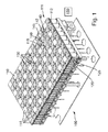
- Fig. 1 shows a sample distribution system 100.
- the sample distribution system 100 has a transport surface 110 on which a number of sample carriers 140 are movable.
- a transport surface 110 on which a number of sample carriers 140 are movable.
- only one sample carrier 140 with a sample container 145 contained therein in the form of a sample tube is shown by way of example.
- an impurity recognition device 111 On the transport surface 110 there is formed an impurity recognition device 111, which in the present case has a capacitive touch-sensitive surface 112 which is formed by means of two plates. Each of the two plates has an electrically conductive coating. Thus, a change in capacitance, which is triggered by an impurity 160 located on the pollution detection device 111, can be detected by suitable measuring devices, not shown.
- capacitive touch-sensitive surfaces With regard to the basic function of capacitive touch-sensitive surfaces, reference should also be made to the relevant specialist literature.
- the area 112 is divided into a plurality of fields 115.
- Each field 115 may be measured individually and independently of the other fields 115 in terms of its capacity. This makes it possible not only to detect but also to locate an impurity 160 on the transport surface 110.
- a number of electromagnetic actuators in the form of electromagnets 120 with respective cores 125 are arranged.
- the sample carrier 140 is a permanent magnet, so that by suitable control of the electromagnets 120, a force can be exerted on the sample carrier 140.
- the sample carrier 140 can be moved over the transport surface 110.
- a number of Hall sensors 130 are furthermore arranged on the transport surface 110.
- each of the panels 115 is associated with either an electromagnet 120 or no solenoid.
- the fields 115 are each square and are distributed adjacent to each other evenly over the transport surface 110.
- an impurity 160 is shown on the transport surface 110.
- the contaminant detection device 111 detects, by means of the capacitive touch-sensitive surface 112 on the corresponding field 115 on which the contaminant 160 is located, a change in capacitance between the two plates. Thus, the contaminant 160 is detected and located.
- an electronic control device 150 For monitoring the contamination detection device 111 and for controlling respective power supplies of the magnets 120, an electronic control device 150 is provided. This can be determined from the contamination detection device 111, i. From the surface 112 and their fields 115, signals detected and locate an impurity 160. As shown, the sample carrier 140 is immediately adjacent to the contaminant 160. In the present case, the controller 150 is configured to stop movement of the sample carrier 140 in such a case. Distributing the contaminant 160 across the transport surface 110 through the sample carrier 140 can be prevented in this way.
- the sample carrier 140 further has a surface 142 that is formed as an impurity detection sensor, wherein the respective contamination detection sensors of all sample carriers are components of the contamination detection device 111.
- the surface or the contamination detection sensor 142 may be formed as a capacitive sensor with two plates with respective electrically conductive coating.
- the sample carrier 140 may include wireless communication means configured to transmit information regarding a detected contaminant to the electronic controller 150. The movement of the sample carrier 140 can be immediately stopped for this case in order to avoid a further distribution of the contamination.
- the controller 150 is further configured to move sample carriers 140 moving on the transport surface 110 around a detected contaminant 160. For this purpose, predeterminable trajectories are recalculated in a suitable manner.
- Sample distribution system 100 is part of a laboratory automation system having a number of pre-analytical, analytical, and post-analytical stations, not shown, disposed adjacent to transport surface 110.
- the sample distribution system 100 serves to transport the sample containers between these stations.
Landscapes
- Chemical & Material Sciences (AREA)
- General Health & Medical Sciences (AREA)
- Life Sciences & Earth Sciences (AREA)
- Health & Medical Sciences (AREA)
- Analytical Chemistry (AREA)
- Biochemistry (AREA)
- Physics & Mathematics (AREA)
- General Physics & Mathematics (AREA)
- Immunology (AREA)
- Pathology (AREA)
- Chemical Kinetics & Catalysis (AREA)
- Electrochemistry (AREA)
- Automatic Analysis And Handling Materials Therefor (AREA)
- Non-Mechanical Conveyors (AREA)
Abstract
Description
- Die Erfindung betrifft ein Probenverteilungssystem mit einer Anzahl von Probenträgern, die zur Aufnahme eines oder mehrerer Probenbehälter ausgebildet sind, und ein Laborautomatisierungssystem mit einem solchen Probenverteilungssystem. Das Probenverteilungssystem ist dazu vorgesehen, Proben in Probenbehältern zu einer Mehrzahl von unterschiedlichen Stationen des Laborautomatisierungssystems zu transportieren.
- Das Dokument
WO 2013/064656 A1 zeigt ein Probenverteilungssystem mit einer Anzahl von Probenträgern, die dazu ausgebildet sind, einen Probenbehälter, beispielsweise in Form eines Probenröhrchens, aufzunehmen. In den Probenbehältern sind zu analysierende Proben, beispielsweise Blutproben, enthalten. Das Probenverteilungssystem weist weiter eine Transportfläche auf, die dazu ausgebildet ist, die Probenträger zu tragen. Durch elektromagnetische Aktuatoren können die Probenträger über die Transportfläche bewegt werden. - Es hat sich herausgestellt, dass bei gattungsgemäßen Probenverteilungssystemen Situationen auftreten können, in welchen Teile einer Probenflüssigkeit aus einem Probenbehälter heraus schwappen kann, wodurch eine Verunreinigung der Transportfläche hervorgerufen werden kann. Dies kann dazu führen, dass nachfolgend über die verunreinigte Stelle bewegte Probenträger ebenfalls verunreinigt werden und somit eine Verteilung der Verunreinigung über die Transportfläche sowie eine mögliche Kreuzkontamination erfolgt.
- Es ist deshalb eine Aufgabe der Erfindung, ein Probenverteilungssystem und ein Laborautomatisierungssystem vorzusehen, die in Bezug auf die Handhabung von Verunreinigungen verbessert sind. Dies wird erfindungsgemäß durch ein Probenverteilungssystem nach Anspruch 1 und ein Laborautomatisierungssystem nach Anspruch 9 gelöst. Der Inhalt der Ansprüche wird durch ausdrückliche Inbezugnahme zum Inhalt der Beschreibung gemacht.
- Die Erfindung betrifft ein Probenverteilungssystem, aufweisend:
- eine Anzahl von Probenträgern, die zur Aufnahme eines oder mehrerer Probenbehälter ausgebildet sind,
- eine Transportfläche, die dazu ausgebildet ist, die Probenträger zu tragen,
- Antriebsmittel, die dazu ausgebildet sind, die Probenträger auf der Transportfläche zu bewegen, und
- eine Verunreinigungserkennungsvorrichtung, die dazu ausgebildet ist, Verunreinigungen auf der Transportfläche zu erkennen.
- Mittels des erfindungsgemäßen Probenverteilungssystems kann eine Verunreinigung auf der Transportfläche erkannt werden, so dass in geeigneter Weise darauf reagiert werden kann.
- Die Verunreinigungserkennungsvorrichtung kann insbesondere dazu ausgebildet sein, Parameter wie Ort, Ausmaß, Typ, Fläche, Dicke und/oder eine andere Eigenschaft der Verunreinigung zu erkennen. Abhängig davon können beispielsweise entsprechende Maßnahmen in angepasster Weise eingeleitet werden.
- Gemäß einer Ausführung weist bei einem Probenverteilungssystem
- ein jeweiliger Probenträger mindestens ein magnetisch wirksames Element auf, das dazu ausgebildet ist, mit einem mittels mindestens eines elektromagnetischen Aktuators erzeugten Magnetfeld derart wechselzuwirken, dass eine Antriebskraft auf den Probenträger bewirkt wird,
- wobei die Antriebsmittel eine Anzahl von elektromagnetischen Aktuatoren aufweisen, die stationär unter der Transportfläche angeordnet sind, wobei die elektromagnetischen Aktuatoren dazu ausgebildet sind, einen Probenträger, der auf der Transportfläche angeordnet ist, durch Ausüben einer magnetischen Kraft auf den Probenträger zu bewegen, und
- wobei das Probenverteilungssystem eine Steuerungseinrichtung aufweist, die dazu ausgebildet ist, die unter der Transportfläche angeordneten elektromagnetischen Aktuatoren derart anzusteuern, dass sich ein jeweiliger Probenträger auf der Transportfläche, insbesondere zweidimensional, entlang einer vorgebbaren Bewegungsbahn bewegt.
- Bei einer derartigen Ausführung werden die Probenträger mittels unter der Transportfläche angeordneter elektromagnetischer Aktuatoren, insbesondere Elektromagnete, bewegt.
- Gemäß einer weiteren Ausführung
- sind die Antriebsmittel als Antriebseinrichtung in einem jeweiligen Probenträger ausgebildet,
- wobei das Probenverteilungssystem eine Steuerungseinrichtung aufweist, die dazu ausgebildet ist, die Antriebseinrichtung eines jeweiligen Probenträgers derart anzusteuern,
- Bei dieser Ausführung sind die Probenträger selbstfahrend ausgebildet. Zum Erhalten von Fahrbefehlen kann beispielsweise eine drahtlose Kommunikation verwendet werden. Die Probenträger können beispielsweise jeweils einen Elektromotor und geeignete Steuerungsmittel aufweisen, um sich selbständig über die Transportfläche zu bewegen.
- Gemäß einer Ausführung weist die Verunreinigungserkennungsvorrichtung eine Anzahl von Sensorfeldern auf, die auf der bzw. über die Transportfläche verteilt sind. Alternativ können die Sensorfelder auch unter der Transportfläche verteilt sein. Die Sensorfelder können gleichmäßig über die (auf/unter/in der) Transportfläche verteilt sein. Mittels der Sensorfelder kann erkannt werden, an welchem Ort auf der Transportfläche eine Verunreinigung vorliegt.
- Gemäß einer Ausführung weist ein jeweiliger Probenträger einen Verunreinigungssensor auf, wobei die jeweiligen Verunreinigungssensoren Bestandteil der Verunreinigungserkennungsvorrichtung sind. Dies kann alternativ oder zusätzlich zu Komponenten der Verunreinigungserkennungsvorrichtung auf der Transportfläche vorgesehen sein. Durch die Anordnung auf dem Probenträger kann ein Verunreinigungssensor bereits ein Warnsignal abgeben und entsprechende Maßnahmen auslösen, wenn eine Verunreinigung bislang nur auf dem Probenträger, jedoch noch nicht auf der Transportfläche angekommen ist. Durch geeignete Maßnahmen, beispielsweise Anhalten des Probenträgers, können weitere Kontaminationen verhindert werden.
- Gemäß einer Ausführung weist die Verunreinigungserkennungsvorrichtung eine kapazitive berührungsempfindliche Fläche auf. Unter einer kapazitiv berührungsempfindlichen Fläche wird eine Fläche verstanden, deren wirksame Kapazität sich in Abhängigkeit von einer Berührung bzw. Verschmutzung verändert. Die kapazitive Fläche kann derart ausgestaltet sein, dass eine Position bzw. ein Ort einer Berührung bzw. Verschmutzung bestimmbar ist. Mittels der kapazitiv berührungsempfindlichen Fläche können kapazitätsverändernde Verunreinigungen zuverlässig erkannt werden. Die berührungsempfindliche Fläche kann insbesondere auf oder unter der Transportfläche angeordnet sein. Sie kann in einzelne Felder unterteilt sein, um eine Positionsbestimmung der Verunreinigung zu ermöglichen.
- Gemäß einer möglichen Ausführung weist die Verunreinigungserkennungsvorrichtung eine erste und eine zweite (Kondensator-) Platte auf, welche jeweils elektrisch leitfähig sind oder elektrisch leitfähig beschichtet sind. Dies ermöglicht eine einfache und zuverlässige Erkennung einer Kapazitätsänderung aufgrund einer Verunreinigung. Eine solche Kombination zweier Platten kann sowohl auf der Transportfläche als auch auf einem Probenträger vorgesehen sein.
- Gemäß einer Ausführung steht die Steuerungseinrichtung in Signalverbindung mit der Verunreinigungserkennungsvorrichtung, wobei die Steuerungseinrichtung dazu ausgebildet ist, in Abhängigkeit von einer erkannten Verunreinigung die Bewegung der Probenträger zu steuern. Damit kann in geeigneter Weise auf eine erkannte Verunreinigung reagiert werden. Sofern die Verunreinigungserkennungsvorrichtung in einem Probenträger ausgebildet ist, kann beispielsweise eine Funkverbindung vorgesehen sein.
- Die Verunreinigungserkennungsvorrichtung kann insbesondere dazu ausgebildet sein, eine Position einer Verunreinigung auf der Transportfläche zu bestimmen, wobei die Steuerungseinrichtung dazu ausgebildet ist, die Bewegungsbahn eines jeweiligen Probenträgers derart zu bestimmen, dass diese nicht über die Position der Verunreinigung verläuft. Damit kann wirksam einer Verteilung der Verunreinigung und Kreuzkontaminationen entgegengewirkt werden.
- Die Verunreinigungserkennungsvorrichtung kann auch dazu ausgebildet sein, Parameter wie Ort, Ausmaß, Typ, Fläche, Dicke und/oder andere Eigenschaften einer Verunreinigung zu bestimmen, wobei die Steuerungseinrichtung auch derartige Eigenschaften bei einer Reaktion auf die Verunreinigung zur Bewegungssteuerung der Probenträger auf der Transportfläche verwenden kann.
- Beispielsweise kann eine Ausschlussfläche, beispielsweise ein Kreis mit einem bestimmten Radius oder ein Quadrat mit einer bestimmten Kantenlänge, um die Position der Verunreinigung herum festgelegt werden, wobei in diese Ausschlussfläche kein Probenträger mehr bewegt wird, bis die Verunreinigung behoben ist.
- Gemäß einer Ausführung kann die Steuerungseinrichtung dazu ausgebildet sein, eine eventuelle Bewegung von Probenträgern, welche sich an der Position der Verunreinigung oder in einem vorgegebenen Abstand dazu befinden, nach Erkennen der Verunreinigung zu stoppen. Damit kann verhindert werden, dass ein Probenträger, welcher sich unmittelbar benachbart zur Verunreinigung befindet und somit mit hoher Wahrscheinlichkeit mit der Verunreinigung kontaminiert wird, auf der Transportfläche weiterfährt und somit die Verunreinigung auf der Transportfläche verteilt. Beispielsweise können alle Probenträger innerhalb der weiter oben beschriebenen Ausschlussfläche angehalten werden. Diese Ausschlussfläche kann auch separat für den Zweck des Anhaltens von Probenträgern verwendet werden.
- Gemäß einer Ausführung ist die Steuerungseinrichtung dazu ausgebildet, bei einer erkannten Verunreinigung alle Probenträger zu stoppen bzw. anzuhalten. Damit kann eine besonders zuverlässige Verhinderung der Verbreitung der Verunreinigung erreicht werden. Außerdem ist diese Ausführung insbesondere dann anwendbar, wenn die Verunreinigungserkennungsvorrichtung nicht dazu ausgebildet ist, die Position einer Verunreinigung auf der Transportfläche zu erkennen.
- Das Laborautomatisierungssystem weist eine Anzahl (beispielsweise zwischen zwei und zwanzig) von präanalytischen und/oder analytischen und/oder postanalytischen Stationen auf, die dazu ausgebildet sind, Probenbehälter und/oder Proben, die in den Probenbehältern enthalten sind, zu bearbeiten oder zu verarbeiten. Das Bearbeiten bzw. Verarbeiten kann beispielsweise ein Lesen eines Barcodes, ein Entfernen einer Kappe auf dem Röhrchen, ein Zentrifugieren der Probe, ein Aliquotieren der Probe, ein Analysieren der Probe usw. umfassen. Das Laborautomatisierungssystem weist weiter ein oben genanntes Probenverteilungssystem zum Transportieren der Probenbehälter zwischen den präanalytischen, analytischen und postanalytischen Stationen auf.
- Die präanalytischen, analytischen und postanalytischen Stationen können beispielsweise mindestens eine Station aus der Menge folgender Stationen aufweisen: eine Kappenentfernungsstation zum Entfernen von Kappen bzw. Verschlüssen auf Probenröhrchen, eine Kappenaufbringstation zum Aufbringen von Kappen bzw. Verschlüssen auf Probenröhrchen, eine Aliquotierstation zum Aliquotieren von Proben, eine Zentrifugierstation zum Zentrifugieren von Proben, eine Archivierstation zum Archivieren von Proben, eine Pipettierstation zum Pipettieren, eine Sortierstation zum Sortieren von Proben bzw. Probenröhrchen, eine Probenröhrchentypbestimmungsstation zum Bestimmen eines Typs eines Probenröhrchens und eine Probenqualitätsbestimmungsstation zum Bestimmen einer Probenqualität.
- Die Erfindung wird nachfolgend unter Bezugnahme auf die Zeichnung detailliert beschrieben. Hierbei zeigt schematisch:
- Fig. 1
- ein Probenverteilungssystem.
-
Fig. 1 zeigt ein Probenverteilungssystem 100. Das Probenverteilungssystem 100 weist eine Transportfläche 110 auf, auf welcher eine Anzahl von Probenträgern 140 verfahrbar sind. Vorliegend ist exemplarisch lediglich ein Probenträger 140 mit einem darin enthaltenen Probenbehälter 145 in Form eines Probenröhrchens gezeigt. - Auf der Transportfläche 110 ist eine Verunreinigungserkennungsvorrichtung 111 ausgebildet, welche vorliegend eine kapazitive berührungsempfindliche Fläche 112 aufweist, die mittels zweier Platten ausgebildet ist. Jede der beiden Platten weist dabei eine elektrisch leitfähige Beschichtung auf. Damit kann eine Kapazitätsänderung, welche durch eine auf der Verunreinigungserkennungsvorrichtung 111 befindliche Verunreinigung 160 ausgelöst wird, durch geeignete, nicht gezeigte Messeinrichtungen erkannt werden. Hinsichtlich der grundsätzlichen Funktion von kapazitiv berührungsempfindlichen Flächen sei auch auf die einschlägige Fachliteratur verwiesen.
- Die Fläche 112 ist in eine Vielzahl von Feldern 115 aufgeteilt. Jedes Feld 115 kann einzeln und unabhängig von den anderen Feldern 115 hinsichtlich seiner Kapazität vermessen werden. Dies ermöglicht es, eine Verunreinigung 160 auf der Transportfläche 110 nicht nur zu erkennen, sondern auch zu lokalisieren.
- Unter der Fläche 112 ist eine Anzahl von elektromagnetischen Aktuatoren in Form von Elektromagneten 120 mit jeweiligen Kernen 125 angeordnet. In dem Probenträger 140 befindet sich ein Permanentmagnet, so dass durch geeignete Ansteuerung der Elektromagnete 120 eine Kraft auf den Probenträger 140 ausgeübt werden kann. Damit kann der Probenträger 140 über die Transportfläche 110 bewegt werden.
- Um eine Position eines Probenträgers 140 auf der Transportfläche 110 zu erkennen, ist weiterhin eine Anzahl von Hall-Sensoren 130 auf der Transportfläche 110 angeordnet.
- Wie gezeigt ist jedem der Felder 115 entweder ein Elektromagnet 120 oder kein Elektromagnet zugeordnet. Die Felder 115 sind jeweils quadratisch und sind aneinander angrenzend gleichmäßig über die Transportfläche 110 verteilt.
- Beispielhaft ist eine Verunreinigung 160 auf der Transportfläche 110 dargestellt. Die Verunreinigungserkennungsvorrichtung 111 detektiert mittels der kapazitiven berührungsempfindlichen Fläche 112 an dem entsprechenden Feld 115, auf welchem sich die Verunreinigung 160 befindet, eine Veränderung der Kapazität zwischen den beiden Platten. Damit ist die Verunreinigung 160 erkannt und lokalisiert.
- Zur Überwachung der Verunreinigungserkennungsvorrichtung 111 und zur Steuerung von jeweiligen Stromversorgungen der Magnete 120 ist eine elektronische Steuerungseinrichtung 150 vorgesehen. Diese kann anhand der von der Verunreinigungserkennungsvorrichtung 111, d.h. von der Fläche 112 bzw. deren Felder 115, gelieferten Signale eine Verunreinigung 160 erkennen und lokalisieren. Wie gezeigt befindet sich der Probenträger 140 unmittelbar benachbart zur Verunreinigung 160. Vorliegend ist die Steuerungseinrichtung 150 derart ausgebildet, dass sie in einem solchen Fall die Bewegung des Probenträgers 140 stoppt. Ein Verteilen der Verunreinigung 160 über die Transportfläche 110 durch den Probenträger 140 kann auf diese Weise verhindert werden.
- Der Probenträger 140 weist des Weiteren eine Oberfläche 142 auf, die als Verunreinigungserkennungssensor ausgebildet ist, wobei die jeweiligen Verunreinigungserkennungssensoren sämtlicher Probenträger Bestandteile der Verunreinigungserkennungsvorrichtung 111 sind.
- Die Oberfläche bzw. der Verunreinigungserkennungssensor 142 kann als kapazitiver Sensor mit zwei Platten mit jeweiliger elektrisch leitfähiger Beschichtung ausgebildet sein. Mittels des Verunreinigungserkennungssensors kann ein Überschwappen einer zumindest teilweise flüssigen Probe, die in dem Probenröhrchen 145 enthalten ist, bereits dann erkannt werden, bevor Bestandteile der Probe auf Transportfläche 110 gelangen.
- Der Probenträger 140 kann über drahtlose Datenübertragungseinrichtung verfügen, die dazu ausgebildet ist, Informationen betreffend eine detektierte Verunreinigung an die elektronische Steuerungseinrichtung 150 zu übertragen. Die Bewegung des Probenträgers 140 kann für diesen Fall unverzüglich gestoppt bzw. angehalten werden, um eine weitere Verteilung der Verunreinigung zu vermeiden.
- Die Steuerungseinrichtung 150 ist ferner dazu ausgebildet, Probenträger 140, welche sich auf der Transportfläche 110 bewegen, um eine erkannte Verunreinigung 160 herum zu bewegen. Hierzu werden vorgebbare Bewegungsbahnen in geeigneter Weise neu berechnet.
- Das Probenverteilungssystem 100 ist Bestandteil eines Laborautomatisierungssystems mit einer Anzahl von nicht näher dargestellten präanalytischen, analytischen und postanalytischen Stationen, die angrenzend an die Transportfläche 110 angeordnet sind. Das Probenverteilungssystem 100 dient zum Transport der Probenbehälter zwischen diesen Stationen.
Claims (9)
- Probenverteilungssystem (100), aufweisend:- eine Anzahl von Probenträgern (140), die zur Aufnahme eines oder mehrerer Probenbehälter (145) ausgebildet sind,- eine Transportfläche (110), die dazu ausgebildet ist, die Probenträger (140) zu tragen,- eine Anzahl von elektromagnetischen Aktuatoren (120), die stationär unter der Transportfläche (110) angeordnet sind, wobei die elektromagnetischen Aktuatoren (120) dazu ausgebildet sind, einen Probenträger (140), der auf der Transportfläche (110) angeordnet ist, durch Ausüben einer magnetischen Kraft auf den Probenträger (140) zu bewegen,- eine Steuerungseinrichtung (150), die dazu ausgebildet ist, die unter der Transportfläche (110) angeordneten elektromagnetischen Aktuatoren (120) derart anzusteuern, dass sich ein jeweiliger Probenträger (140) auf der Transportfläche (110) entlang einer vorgebbaren Bewegungsbahn bewegt, und- eine Verunreinigungserkennungsvorrichtung (111), die dazu ausgebildet ist, Verunreinigungen (160) auf der Transportfläche (110) zu erkennen.
- Probenverteilungssystem (100) nach Anspruch 1, dadurch gekennzeichnet, dass- die Verunreinigungserkennungsvorrichtung (111) eine Anzahl von Sensorfeldern (115) aufweist, die über die Transportfläche (110) verteilt sind.
- Probenverteilungssystem (100) nach Anspruch 1 oder 2, dadurch gekennzeichnet, dass- ein jeweiliger Probenträger (140) einen Verunreinigungssensor (142) aufweist, wobei die jeweiligen Verunreinigungssensoren (142) Bestandteil der Verunreinigungserkennungsvorrichtung (111) sind.
- Probenverteilungssystem (100) nach einem der vorhergehenden Ansprüche, dadurch gekennzeichnet, dass- die Verunreinigungserkennungsvorrichtung (111) eine kapazitive berührungsempfindliche Fläche (112) aufweist.
- Probenverteilungssystem (100) nach einem der vorhergehenden Ansprüche, dadurch gekennzeichnet, dass- die Steuerungseinrichtung (150) in Signalverbindung mit der Verunreinigungserkennungsvorrichtung (111) steht, wobei die Steuerungseinrichtung (150) dazu ausgebildet ist, in Abhängigkeit von einer erkannten Verunreinigung (160) die Bewegung der Probenträger (140) zu steuern.
- Probenverteilungssystem (100) nach Anspruch 5, dadurch gekennzeichnet, dass- die Verunreinigungserkennungsvorrichtung (111) dazu ausgebildet, eine Position einer Verunreinigung (160) auf der Transportfläche (110) zu bestimmen, wobei die Steuerungseinrichtung (150) dazu ausgebildet ist, die Bewegungsbahn eines jeweiligen Probenträgers (140) derart zu bestimmen, dass diese nicht über die Position der Verunreinigung (160) verläuft.
- Probenverteilungssystem (100) nach Anspruch 6, dadurch gekennzeichnet, dass- die Steuerungseinrichtung (150) dazu ausgebildet ist, Probenträger (140), welche sich an der Position der Verunreinigung (160) oder in einem vorgegebenen Abstand dazu befinden, nach Erkennen der Verunreinigung (160) anzuhalten.
- Probenverteilungssystem (100) nach einem der vorhergehenden Ansprüche, dadurch gekennzeichnet, dass- die Steuerungseinrichtung (150) dazu ausgebildet ist, bei einer erkannten Verunreinigung (160) alle Probenträger (140) anzuhalten.
- Laborautomatisierungssystem, aufweisend:- eine Anzahl von präanalytischen, analytischen und/oder postanalytischen Stationen, die dazu ausgebildet sind, Probenbehälter und/oder Proben, die in jeweiligen Probenbehältern enthalten sind, zu bearbeiten, und- ein Probenverteilungssystem zum Transportieren der Probenbehälter zwischen den präanalytischen, analytischen und/oder postanalytischen Stationen nach einem der vorhergehenden Ansprüche.
Priority Applications (3)
| Application Number | Priority Date | Filing Date | Title |
|---|---|---|---|
| EP14162952.7A EP2927695B1 (de) | 2014-03-31 | 2014-03-31 | Probenverteilungssystem und Laborautomatisierungssystem |
| JP2015049273A JP6055503B2 (ja) | 2014-03-31 | 2015-03-12 | 試料分配システムおよび実験室自動化システム |
| US14/665,390 US9658241B2 (en) | 2014-03-31 | 2015-03-23 | Sample distribution system and laboratory automation system |
Applications Claiming Priority (1)
| Application Number | Priority Date | Filing Date | Title |
|---|---|---|---|
| EP14162952.7A EP2927695B1 (de) | 2014-03-31 | 2014-03-31 | Probenverteilungssystem und Laborautomatisierungssystem |
Publications (2)
| Publication Number | Publication Date |
|---|---|
| EP2927695A1 true EP2927695A1 (de) | 2015-10-07 |
| EP2927695B1 EP2927695B1 (de) | 2018-08-22 |
Family
ID=50478208
Family Applications (1)
| Application Number | Title | Priority Date | Filing Date |
|---|---|---|---|
| EP14162952.7A Active EP2927695B1 (de) | 2014-03-31 | 2014-03-31 | Probenverteilungssystem und Laborautomatisierungssystem |
Country Status (3)
| Country | Link |
|---|---|
| US (1) | US9658241B2 (de) |
| EP (1) | EP2927695B1 (de) |
| JP (1) | JP6055503B2 (de) |
Families Citing this family (62)
| Publication number | Priority date | Publication date | Assignee | Title |
|---|---|---|---|---|
| DE102010028769A1 (de) | 2010-05-07 | 2011-11-10 | Pvt Probenverteiltechnik Gmbh | System zum Transportieren von Behältern zwischen unterschiedlichen Stationen und Behälterträger |
| EP2589966A1 (de) | 2011-11-04 | 2013-05-08 | Roche Diagnostics GmbH | Laborprobenverteilungssystem und entsprechendes Betriebsverfahren |
| EP2589967A1 (de) | 2011-11-04 | 2013-05-08 | Roche Diagnostics GmbH | Laborprobenverteilungssystem und entsprechendes Betriebsverfahren |
| EP2589968A1 (de) | 2011-11-04 | 2013-05-08 | Roche Diagnostics GmbH | Laborprobenverteilungssystem, Laborsystem und Betriebsverfahren |
| DE102014202843B3 (de) | 2014-02-17 | 2014-11-06 | Roche Pvt Gmbh | Transportvorrichtung, Probenverteilungssystem und Laborautomatisierungssystem |
| DE102014202838B3 (de) | 2014-02-17 | 2014-11-06 | Roche Pvt Gmbh | Transportvorrichtung, Probenverteilungssystem und Laborautomatierungssystem |
| EP2927163B1 (de) | 2014-03-31 | 2018-02-28 | Roche Diagnostics GmbH | Vertikalfördervorrichtung, Probenverteilungssystem und Laborautomatisierungssystem |
| EP2927167B1 (de) | 2014-03-31 | 2018-04-18 | F. Hoffmann-La Roche AG | Versandvorrichtung, Probenverteilungssystem und Laborautomatisierungssystem |
| EP2927168A1 (de) | 2014-03-31 | 2015-10-07 | Roche Diagniostics GmbH | Transportvorrichtung, Probenverteilungssystem und Laborautomatisierungssystem |
| EP2927625A1 (de) | 2014-03-31 | 2015-10-07 | Roche Diagniostics GmbH | Probenverteilungssystem und Laborautomatisierungssystem |
| EP2957914B1 (de) | 2014-06-17 | 2018-01-03 | Roche Diagnostics GmbH | Laborprobenverteilungssystem und Laborautomatisierungssystem |
| EP2977766A1 (de) * | 2014-07-24 | 2016-01-27 | Roche Diagniostics GmbH | Laborprobenverteilungssystem und Laborautomatisierungssystem |
| EP2995580A1 (de) | 2014-09-09 | 2016-03-16 | Roche Diagniostics GmbH | Laborprobenverteilungssystem und Laborautomatisierungssystem |
| EP2995960B1 (de) | 2014-09-09 | 2020-07-15 | Roche Diagniostics GmbH | Laborprobenverteilungssystem und Verfahren zur Kalibrierung von magnetischen Sensoren |
| US9952242B2 (en) | 2014-09-12 | 2018-04-24 | Roche Diagnostics Operations, Inc. | Laboratory sample distribution system and laboratory automation system |
| EP2995958A1 (de) | 2014-09-15 | 2016-03-16 | Roche Diagniostics GmbH | Verfahren zum Betrieb einer Laborprobe Verteilungssystem, Laborprobenverteilungssystems und Laborautomatisierungssystem |
| EP3006943B1 (de) | 2014-10-07 | 2020-04-22 | Roche Diagniostics GmbH | Modul für ein Laborprobenverteilungssystem, Laborprobenverteilungssystem und Laborautomatisierungssystem |
| EP3016116A1 (de) | 2014-11-03 | 2016-05-04 | Roche Diagniostics GmbH | Leiterplattenanordnung, Spule für ein Laborprobenverteilungssystem, Laborprobenverteilungssystem und Laborautomatisierungssystem |
| EP3070479B1 (de) | 2015-03-16 | 2019-07-03 | Roche Diagniostics GmbH | Transportträger, laborfrachtverteilungssystem und laborautomatisierungssystem |
| EP3537160B1 (de) | 2015-03-23 | 2020-08-12 | Roche Diagnostics GmbH | Laborprobenverteilungssystem und laborautomatisierungssystem |
| EP3096145B1 (de) | 2015-05-22 | 2019-09-04 | Roche Diagniostics GmbH | Verfahren zum betrieb eines laborautomatisierungssystems und laborautomatisierungssystem |
| EP3095739A1 (de) | 2015-05-22 | 2016-11-23 | Roche Diagniostics GmbH | Verfahren zum betrieb eines laborprobenverteilungssystems, laborprobenverteilungssystem und laborautomatisierungssystem |
| EP3096146A1 (de) | 2015-05-22 | 2016-11-23 | Roche Diagniostics GmbH | Verfahren zum betrieb eines laborprobenverteilungssystems, laborprobenverteilungssystem und laborautomatisierungssystem |
| EP3112874A1 (de) | 2015-07-02 | 2017-01-04 | Roche Diagnostics GmbH | Speichermodul, verfahren zum betrieb eines laborautomatisierungssystems und laborautomatisierungssystem |
| EP3121603A1 (de) | 2015-07-22 | 2017-01-25 | Roche Diagnostics GmbH | Probenbehälterträger, laborprobenverteilungssystem und laborautomatisierungssystem |
| EP3139175B1 (de) | 2015-09-01 | 2021-12-15 | Roche Diagnostics GmbH | Laborfrachtverteilungssystem, laborautomatisierungssystem und verfahren zum betrieb eines laborfrachtverteilungssystems |
| EP3153867B1 (de) | 2015-10-06 | 2018-11-14 | Roche Diagniostics GmbH | Verfahren zur konfiguration eines laborautomatisierungssystems, laborprobenverteilungssystem und laborautomatisierungssystem |
| EP3153866A1 (de) | 2015-10-06 | 2017-04-12 | Roche Diagnostics GmbH | Verfahren zur bestimmung einer übergabeposition und laborautomatisierungssystem |
| EP3156352B1 (de) | 2015-10-13 | 2019-02-27 | Roche Diagniostics GmbH | Laborprobenverteilungssystem und laborautomatisierungssystem |
| EP3156353B1 (de) | 2015-10-14 | 2019-04-03 | Roche Diagniostics GmbH | Verfahren zum drehen eines probenbehälterträgers, laborprobenverteilungssystem und laborautomatisierungssystem |
| EP3211429A1 (de) | 2016-02-26 | 2017-08-30 | Roche Diagnostics GmbH | Transportvorrichtung mit gefliester fahroberfläche |
| EP3211428A1 (de) | 2016-02-26 | 2017-08-30 | Roche Diagnostics GmbH | Transportvorrichtungseinheit für ein laborprobenverteilungssystem |
| EP3211430A1 (de) | 2016-02-26 | 2017-08-30 | Roche Diagnostics GmbH | Transportvorrichtung mit grundplattenmodulen |
| ES2900187T3 (es) | 2016-03-17 | 2022-03-16 | Siemens Healthcare Diagnostics Products Gmbh | Sistema de aviso para resultados de medición potencialmente erróneos en un analizador automático |
| CN109196363A (zh) | 2016-06-03 | 2019-01-11 | 豪夫迈·罗氏有限公司 | 实验室样品分配系统和实验室自动化系统 |
| EP3255519B1 (de) | 2016-06-09 | 2019-02-20 | Roche Diagniostics GmbH | Laborprobenverteilungssystem und verfahren zum betrieb eines laborprobenverteilungssystems |
| EP3260867A1 (de) | 2016-06-21 | 2017-12-27 | Roche Diagnostics GmbH | Verfahren zur bestimmung einer übergabeposition und laborautomatisierungssystem |
| JP6752350B2 (ja) | 2016-08-04 | 2020-09-09 | エフ.ホフマン−ラ ロシュ アーゲーF. Hoffmann−La Roche Aktiengesellschaft | ラボラトリ試料分配システム及びラボラトリ自動化システム |
| EP3509953A1 (de) | 2016-09-09 | 2019-07-17 | The Procter and Gamble Company | System und verfahren zum gleichzeitigen befüllen von behältern mit unterschiedlichen formen und/oder grössen |
| CN109661623A (zh) | 2016-09-09 | 2019-04-19 | 宝洁公司 | 用于在单条生产线上同时生产不同产品的方法 |
| US10996232B2 (en) | 2016-09-09 | 2021-05-04 | The Procter & Gamble Company | System and method for independently routing container-loaded vehicles to create different finished products |
| JP6810253B2 (ja) | 2016-09-09 | 2021-01-06 | ザ プロクター アンド ギャンブル カンパニーThe Procter & Gamble Company | 要求に基づいて製品を生産するためのシステム及び方法 |
| US10640249B2 (en) | 2016-09-09 | 2020-05-05 | The Procter & Gamble Company | Track system for creating finished products |
| CA3035965C (en) | 2016-09-09 | 2022-01-11 | The Procter & Gamble Company | System and method for simultaneously filling containers with different fluent compositions |
| US11584628B2 (en) | 2016-09-09 | 2023-02-21 | The Procter & Gamble Company | System and method for independently routing vehicles and delivering containers and closures to unit operation systems |
| EP3330717B1 (de) | 2016-12-01 | 2022-04-06 | Roche Diagnostics GmbH | Laborprobenverteilungssystem und laborautomatisierungssystem |
| EP3343232B1 (de) | 2016-12-29 | 2021-09-15 | Roche Diagnostics GmbH | Laborprobenverteilungssystem und laborautomatisierungssystem |
| EP3355065B1 (de) | 2017-01-31 | 2021-08-18 | Roche Diagnostics GmbH | Laborprobenverteilungssystem und laborautomatisierungssystem |
| EP3357842B1 (de) | 2017-02-03 | 2022-03-23 | Roche Diagnostics GmbH | Laborautomatisierungssystem |
| EP3410123B1 (de) | 2017-06-02 | 2023-09-20 | Roche Diagnostics GmbH | Verfahren zum betrieb eines laborprobenverteilungssystems, laborprobenverteilungssystem und laborautomatisierungssystem |
| EP3428653B1 (de) | 2017-07-13 | 2021-09-15 | Roche Diagnostics GmbH | Verfahren zum betreiben eines laborprobenverteilungssystems, laborprobenverteilungssystem und laborautomatisierungssystem |
| EP3456415B1 (de) | 2017-09-13 | 2021-10-20 | Roche Diagnostics GmbH | Probenbehälterträger, laborprobenverteilungssystem und laborautomatisierungssystem |
| EP3457144B1 (de) | 2017-09-13 | 2021-10-20 | Roche Diagnostics GmbH | Probenbehälterträger, laborprobenverteilungssystem und laborautomatisierungssystem |
| EP3537159B1 (de) | 2018-03-07 | 2022-08-31 | Roche Diagnostics GmbH | Verfahren zum betrieb eines laborprobenverteilungssystems, laborprobenverteilungssystem und laborautomatisierungssystem |
| EP3540443B1 (de) | 2018-03-16 | 2023-08-30 | Roche Diagnostics GmbH | Laborsystem, laborprobenverteilungssystem und laborautomationssystem |
| JP7304831B2 (ja) * | 2020-02-18 | 2023-07-07 | 株式会社日立ハイテク | 搬送装置及び搬送装置を有する検体分析システム |
| EP3925911B1 (de) | 2020-06-19 | 2023-05-24 | Roche Diagnostics GmbH | Laborprobenverteilungssystem und entsprechendes verfahren zum betrieb |
| EP3940388B1 (de) | 2020-07-15 | 2024-04-10 | Roche Diagnostics GmbH | Laborprobenverteilungssystem und verfahren zum betrieb davon |
| EP4001923B1 (de) * | 2020-11-23 | 2024-06-05 | Roche Diagnostics GmbH | Laborprobenverteilungssystem und laborautomatisierungssystem |
| US11747356B2 (en) | 2020-12-21 | 2023-09-05 | Roche Diagnostics Operations, Inc. | Support element for a modular transport plane, modular transport plane, and laboratory distribution system |
| JP7427114B2 (ja) * | 2020-12-23 | 2024-02-02 | 株式会社日立ハイテク | 検体搬送装置、および検体の搬送方法 |
| US20250085304A1 (en) * | 2021-08-24 | 2025-03-13 | Hitachi High-Tech Corporation | Sample conveying device and sample conveying method |
Citations (3)
| Publication number | Priority date | Publication date | Assignee | Title |
|---|---|---|---|---|
| JP2009300402A (ja) * | 2008-06-17 | 2009-12-24 | Olympus Corp | 分析装置及び分析方法 |
| WO2010129715A1 (en) * | 2009-05-05 | 2010-11-11 | Cypress Semiconductor Corporation | Spill-over detection method and system |
| WO2013064656A1 (en) | 2011-11-04 | 2013-05-10 | Roche Diagnostics Gmbh | Laboratory sample distribution system and corresponding method of operation |
Family Cites Families (185)
| Publication number | Priority date | Publication date | Assignee | Title |
|---|---|---|---|---|
| US3273727A (en) | 1966-09-20 | Load handling apparatus | ||
| US2653485A (en) | 1950-07-20 | 1953-09-29 | Ramsey Chain Company Inc | Silent chain |
| US3653485A (en) | 1971-03-05 | 1972-04-04 | Transportation Technology | An air bearing conveyor |
| US3901656A (en) | 1972-08-24 | 1975-08-26 | American Monitor Corp | Apparatus and method for preparing and presenting serum chemistries for analyzation |
| DE2722865C2 (de) | 1977-05-20 | 1986-06-19 | Krupp Polysius Ag, 4720 Beckum | Rohrpostförderanlage für Feingutproben |
| US4150666A (en) | 1977-06-27 | 1979-04-24 | Sherwood Medical Industries Inc. | Tube holder for blood collection tubes of different sizes |
| SU685591A1 (ru) | 1977-08-01 | 1979-09-15 | Украинский Государственный Институт По Проектированию Металлургических Заводов | Патрон пневмопочты |
| JPS56147209A (en) * | 1980-04-16 | 1981-11-16 | Hitachi Kiden Kogyo Ltd | Automatic steering method for unattended carrying vehicle |
| US4544068A (en) | 1983-08-16 | 1985-10-01 | The United States Of America As Represented By The Administrator Of The National Aeronautics And Space Administration | Laboratory glassware rack for seismic safety |
| JPS60223481A (ja) | 1984-04-18 | 1985-11-07 | Nippon Telegr & Teleph Corp <Ntt> | 磁気浮上案内装置 |
| JPS6181323A (ja) | 1984-09-27 | 1986-04-24 | Mitsubishi Chem Ind Ltd | 整列物体の移動装置 |
| GB2165515A (en) | 1984-10-12 | 1986-04-16 | Mitsubishi Chem Ind | Conveyor |
| JPS6194925A (ja) | 1984-10-12 | 1986-05-13 | Mitsubishi Chem Ind Ltd | 搬送用装置 |
| JPS61217434A (ja) | 1985-03-20 | 1986-09-27 | Mitsubishi Chem Ind Ltd | 搬送用装置 |
| JPS61174031A (ja) | 1985-01-29 | 1986-08-05 | Youichi Oohira | リニア誘導モ−タ形x−yアクチユエ−タを用いた分岐を目的とする搬送装置 |
| JPS62100161A (ja) | 1985-10-23 | 1987-05-09 | Shin Etsu Chem Co Ltd | 平面モ−タ |
| US4771237A (en) | 1986-02-19 | 1988-09-13 | Panametrics | Method and apparatus for calibrating a displacement probe using a polynomial equation to generate a displacement look-up table |
| JPS6331918A (ja) | 1986-07-16 | 1988-02-10 | フエコ・エンジニア−ド・システムズ・インコ−ポレ−テツド | 回転および引込可能な容器保持装置およびそのコンベア |
| JPS6348169A (ja) | 1986-08-14 | 1988-02-29 | Fuji Elelctrochem Co Ltd | 圧電アクチユエ−タ |
| JPH0239554Y2 (de) | 1986-11-15 | 1990-10-23 | ||
| JPS63290101A (ja) | 1987-05-22 | 1988-11-28 | Toshiba Corp | リニアモ−タ式搬送装置 |
| JPH01148966A (ja) | 1987-12-04 | 1989-06-12 | Hitachi Kiden Kogyo Ltd | 検体搬送装置 |
| JPH01266860A (ja) | 1988-04-19 | 1989-10-24 | Yukitaka Furukawa | 試験管を冷却することが出来る試験管保持器具 |
| JP2585747B2 (ja) | 1988-09-21 | 1997-02-26 | 株式会社ダイフク | リニアモータ利用の搬送設備 |
| JPH02163637A (ja) | 1988-12-16 | 1990-06-22 | Fuji Photo Film Co Ltd | 液体化学分析装置 |
| DE3909786A1 (de) | 1989-03-24 | 1990-09-27 | Schlafhorst & Co W | Vorrichtung zum transportieren von kopsen und huelsen zwischen im verlauf des transportes wechselnden ebenen |
| DE4011797C2 (de) | 1989-06-10 | 1998-02-12 | Schlafhorst & Co W | Transportsystem für eine automatische Textilmaschine zum gesteuerten Führen von Paletten entlang vorgegebener Transportwege |
| JPH03112393A (ja) | 1989-09-21 | 1991-05-13 | Kao Corp | 搬送装置 |
| JPH03192013A (ja) | 1989-12-21 | 1991-08-21 | Toshiba Corp | 表示装置 |
| EP0529157A1 (de) | 1991-08-22 | 1993-03-03 | Mitsubishi Jukogyo Kabushiki Kaisha | Wechselstrom-Transportsystem mit magnetischer Schwebewirkung |
| JPH0569350A (ja) | 1991-09-11 | 1993-03-23 | Toshiba Corp | 軌道走行式ロボツト設備の保全装置 |
| JPH05180847A (ja) | 1991-12-31 | 1993-07-23 | Hiranuma Sangyo Kk | 自動分析装置用サイクラ |
| DE69308493T2 (de) | 1992-06-29 | 1997-10-23 | Dade Int Inc | Träger für proberöhrchen |
| EP0648698B1 (de) | 1992-07-07 | 1998-01-07 | Ebara Corporation | Durch magnetische wirkung schwebende transportvorrichtung |
| JPH0626808A (ja) | 1992-07-09 | 1994-02-04 | Ebara Corp | センサターゲット |
| EP0590222A1 (de) | 1992-09-30 | 1994-04-06 | STMicroelectronics S.r.l. | Magnetischer Lagegeber |
| EP0601213A1 (de) | 1992-10-29 | 1994-06-15 | Hamilton Bonaduz AG | Vorrichtung zum Transportieren von Waren |
| JPH06148198A (ja) | 1992-11-05 | 1994-05-27 | Hitachi Ltd | 分析機器の汚染防止装置 |
| JPH06156730A (ja) | 1992-11-13 | 1994-06-03 | Ebara Corp | 搬送装置 |
| JP3387951B2 (ja) | 1993-01-19 | 2003-03-17 | 株式会社荏原製作所 | 基板保管装置 |
| JPH07228345A (ja) | 1994-02-14 | 1995-08-29 | Ebara Corp | トンネル搬送装置 |
| JP2574126B2 (ja) | 1994-02-28 | 1997-01-22 | 照明 伊藤 | 検体遠心分離処理方法およびその装置 |
| US5636548A (en) | 1994-05-16 | 1997-06-10 | Tesoro Alaska Petroleum Company | Analog hall-effect liquid level detector and method |
| US5523131A (en) | 1994-11-01 | 1996-06-04 | Innovative Premiums Inc. | Self-propelled table novelty device |
| IL118232A (en) | 1995-05-15 | 2001-07-24 | Smithkline Beecham Corp | Bottle holder |
| US5735387A (en) | 1995-07-14 | 1998-04-07 | Chiron Diagnostics Corporation | Specimen rack handling system |
| US5720377A (en) | 1995-07-14 | 1998-02-24 | Chiron Diagnostics Corporation | Magnetic conveyor system |
| EP0775650A1 (de) | 1995-11-24 | 1997-05-28 | André Dr. von Froreich | Fördersystem, insbesondere für Materialträger für den labormedizinischen Einsatz |
| US5788929A (en) | 1996-03-12 | 1998-08-04 | Nesti; Edmund D. | Sample temperature protection rack |
| JPH1159901A (ja) | 1997-08-11 | 1999-03-02 | Murata Mach Ltd | キャリヤー移動装置 |
| JP3444760B2 (ja) | 1997-09-11 | 2003-09-08 | 株式会社日立製作所 | 検体搬送システム |
| US6838051B2 (en) | 1999-05-03 | 2005-01-04 | Ljl Biosystems, Inc. | Integrated sample-processing system |
| US5897090A (en) | 1997-11-13 | 1999-04-27 | Bayer Corporation | Puck for a sample tube |
| GB2331838A (en) | 1997-11-24 | 1999-06-02 | Coolbox | Portable,thermoelectric,temperature controlled receptacles. |
| JPH11264828A (ja) | 1998-03-19 | 1999-09-28 | Hitachi Ltd | 検体搬送システム |
| JPH11304812A (ja) | 1998-04-20 | 1999-11-05 | Hitachi Ltd | 検体処理システム |
| JP3301965B2 (ja) | 1998-05-19 | 2002-07-15 | アロカ株式会社 | ラベル読取り装置 |
| CA2273729A1 (en) | 1998-07-14 | 2000-01-14 | Bayer Corporation | Robotics for transporting containers and objects within an automated analytical instrument and service tool for servicing robotics |
| US6279728B1 (en) | 1998-07-20 | 2001-08-28 | Norbert G Jung | Electro-magnetic conveyor |
| JP3930977B2 (ja) | 1998-07-31 | 2007-06-13 | 株式会社日立製作所 | 検体処理システム |
| JP3668618B2 (ja) | 1998-09-29 | 2005-07-06 | 株式会社日立製作所 | 自動分析装置 |
| JP2000105243A (ja) * | 1998-09-29 | 2000-04-11 | Hitachi Ltd | ラック搬送装置 |
| JP4136187B2 (ja) | 1999-05-14 | 2008-08-20 | シスメックス株式会社 | 検体移し替え装置 |
| US6062398A (en) | 1999-07-21 | 2000-05-16 | Thalmayr; Hermann | Insert for holding test tubes in a conveyor capsule of a pneumatic tube conveyor system |
| US6429016B1 (en) | 1999-10-01 | 2002-08-06 | Isis Pharmaceuticals, Inc. | System and method for sample positioning in a robotic system |
| JP3424623B2 (ja) | 1999-10-29 | 2003-07-07 | 日立エンジニアリング株式会社 | 検体仕分け装置 |
| EP1122194B1 (de) | 2000-02-01 | 2004-11-10 | Johnson & Johnson Vision Care, Inc. | Vorrichtung und Verfahren für automatisiertes Warenlager |
| JP2001240245A (ja) | 2000-03-01 | 2001-09-04 | Auto Cs Engineering Co Ltd | 圧縮空気による搬送システムおよび搬送装置 |
| US20040050836A1 (en) | 2000-09-29 | 2004-03-18 | Nesbitt Geoffrey John | Assembly of an integrated vessel transporter and at least one reaction vessel and integrated vessel transporter for transporting a chemical substance |
| DE10050085C1 (de) | 2000-10-10 | 2001-10-31 | Jochem Koetting | Verschlußelement und Verschlußsystem für Behältnisse und Gefäße |
| US6825041B2 (en) | 2001-03-16 | 2004-11-30 | Beckman Coulter, Inc. | Method and system for automated immunochemistry analysis |
| AUPR854301A0 (en) | 2001-10-29 | 2001-11-29 | Martin Gessner Pty Ltd | Conveying apparatus |
| US6571934B1 (en) | 2001-11-14 | 2003-06-03 | Dade Behring Inc. | Bi-directional magnetic sample rack conveying system |
| JP3527904B2 (ja) | 2002-02-28 | 2004-05-17 | 照明 伊藤 | 試験管ホルダー |
| JP4105164B2 (ja) | 2002-09-26 | 2008-06-25 | バイオパス・オートメーション・エル・エル・シー | 組織標本のハンドリングおよび包埋を自動化する機器および方法 |
| JP3675791B2 (ja) | 2002-11-01 | 2005-07-27 | 照明 伊藤 | バーコード化装置 |
| TWI249574B (en) | 2002-11-19 | 2006-02-21 | Sanyo Electric Co | Preserving device |
| GB2402481A (en) | 2003-06-04 | 2004-12-08 | Genial Genetic Solutions Ltd | Multi-well rotatable analyser |
| US7648835B2 (en) | 2003-06-06 | 2010-01-19 | Micronics, Inc. | System and method for heating, cooling and heat cycling on microfluidic device |
| JP3910157B2 (ja) | 2003-06-11 | 2007-04-25 | ファナック株式会社 | ロボット装置 |
| DE10340143A1 (de) | 2003-08-26 | 2005-03-31 | SSI Schäfer PEEM GmbH | Kommissionierplatz und Verfahren zum Kommissionieren |
| US20050079103A1 (en) | 2003-10-14 | 2005-04-14 | Merrit Jacobs | Moving evaporation control cover |
| US6971503B2 (en) * | 2003-11-26 | 2005-12-06 | Cynthia Thompson | Conveyor belt cleaning apparatus |
| JP4680935B2 (ja) | 2004-01-08 | 2011-05-11 | ジクスト、ベルンハルト | 冷凍材料の冷却保持用輸送容器 |
| US7078082B2 (en) | 2004-01-15 | 2006-07-18 | Sonoco Development, Inc. | Dual-functioning mechanism for startup during winding of web material and for splicing during unwinding |
| US7850914B2 (en) | 2004-03-05 | 2010-12-14 | Beckman Coulter, Inc. | Specimen-transport module for a multi-instrument clinical workcell |
| US7331474B2 (en) | 2004-03-05 | 2008-02-19 | Beckman Coulter, Inc. | Specimen-container rack for automated clinical instrument |
| US7028831B2 (en) | 2004-03-05 | 2006-04-18 | Beckman Coulter, Inc. | Magnetic specimen-transport system for automated clinical instrument |
| JP2005249740A (ja) | 2004-03-08 | 2005-09-15 | Olympus Corp | サンプルラック搬送装置及びサンプルラック搬送方法 |
| US7382258B2 (en) | 2004-03-19 | 2008-06-03 | Applera Corporation | Sample carrier device incorporating radio frequency identification, and method |
| JP3905094B2 (ja) | 2004-04-07 | 2007-04-18 | 株式会社アイディエス | 自走式検体ホルダの搬送システム |
| JP4098272B2 (ja) | 2004-04-26 | 2008-06-11 | 株式会社アイディエス | 試験管のバーコード読取り装置 |
| US20060000296A1 (en) | 2004-07-02 | 2006-01-05 | Salter Jason P | Synchronization of sample and data collection |
| JPWO2006006730A1 (ja) | 2004-07-15 | 2008-05-01 | 株式会社ニコン | 平面モータ装置、ステージ装置、露光装置及びデバイスの製造方法 |
| US7862579B2 (en) | 2004-07-28 | 2011-01-04 | Ethicon Endo-Surgery, Inc. | Electroactive polymer-based articulation mechanism for grasper |
| US20060246576A1 (en) | 2005-04-06 | 2006-11-02 | Affymetrix, Inc. | Fluidic system and method for processing biological microarrays in personal instrumentation |
| FR2888328B1 (fr) | 2005-07-08 | 2013-09-20 | Horiba Abx Sas | Procede automatise de preparation d'analyse d'echantillons de sang total et dispositif automatise pour sa mise en oeuvre |
| US7566168B2 (en) | 2005-08-19 | 2009-07-28 | Shake Awake Products, LLC | Apparatus and method for determining the amount of time until a desired temperature is reached |
| US8346382B2 (en) | 2005-08-25 | 2013-01-01 | Coldtrack, Llc | Hierarchical sample storage system |
| US20070116611A1 (en) | 2005-11-14 | 2007-05-24 | Demarco Nicholas | Fraction collection system |
| JP4113891B2 (ja) * | 2005-12-20 | 2008-07-09 | ジェイ・エス・ケー株式会社 | 静電容量型検出装置 |
| CN201045617Y (zh) | 2006-04-21 | 2008-04-09 | 北京赛科希德科技发展有限公司 | 用于全自动凝血测量的测试杯连续输送装置 |
| US7776270B2 (en) | 2006-04-25 | 2010-08-17 | Ecocap's S.R.L. | Resealer of test tubes for clinical analyses fed from ready-to-use containers of sealing tape |
| JP2007309675A (ja) | 2006-05-16 | 2007-11-29 | Olympus Corp | サンプルラック供給回収装置 |
| JP4586992B2 (ja) | 2006-05-23 | 2010-11-24 | 株式会社ダイフク | 物品処理設備 |
| JP2007322289A (ja) * | 2006-06-01 | 2007-12-13 | Olympus Corp | 搬送装置 |
| US7666366B2 (en) | 2006-07-10 | 2010-02-23 | Exxonmobil Chemical Patents Inc. | Internal loop reactor and Oxo process using same |
| DE102006032435A1 (de) | 2006-07-13 | 2008-01-17 | Sixt, Bernhard, Dr. | Transportbehälter zur Kühlhaltung von gefrorenem Gut |
| JP4336360B2 (ja) | 2006-09-20 | 2009-09-30 | 株式会社アイディエス | 検体前処理搬送装置 |
| DE102007013237A1 (de) | 2007-03-15 | 2008-09-18 | Joint Analytical Systems Gmbh | Lagersystem |
| US7681466B2 (en) | 2007-05-01 | 2010-03-23 | Siemens Healthcare Diagnostics Inc. | Programmable random access sample handler for use within and automated laboratory system |
| JP3133890U (ja) | 2007-05-16 | 2007-07-26 | 株式会社日立ハイテクノロジーズ | 検体処理システム |
| DE102007025822A1 (de) | 2007-06-02 | 2008-12-18 | Lars Bergmann | Kombinierbares Flächenelement mit einer Vielzahl von ansteuerbaren Wandlerelementen |
| EP2153295B1 (de) | 2007-06-06 | 2014-11-05 | Path | Chemische temperatursteuerung |
| CN101680548A (zh) | 2007-06-19 | 2010-03-24 | 株式会社开滋 | 轴封装置和使用该轴封装置的阀结构 |
| US8556564B2 (en) | 2007-06-26 | 2013-10-15 | Siemens Healthcare Diagnostics Inc. | Mobile sample storage and retrieval unit for a laboratory automated sample handling worksystem |
| KR101307859B1 (ko) | 2007-07-19 | 2013-09-12 | 삼성전자주식회사 | 생화학 분석기 및 그 내부 온도 제어 방법 |
| JP2009062188A (ja) | 2007-09-10 | 2009-03-26 | Tsubakimoto Chain Co | リニヤ誘導モータ形x−yアクチュエータを用いた仕分装置 |
| US20090128139A1 (en) | 2007-11-20 | 2009-05-21 | Drenth Joseph B | Magnet position locator |
| ITMI20072254A1 (it) | 2007-11-30 | 2009-06-01 | Dachi S R L | "impianto di identificazione, trasporto ed indirizzamento automatico di campioni di materiale biologico" |
| ITMI20072255A1 (it) | 2007-11-30 | 2009-06-01 | Dachi S R L | "apparato di carico e scarico automatico di provette di materiale biologico in un impianto di posta pneumatica" |
| ITFI20070275A1 (it) | 2007-12-07 | 2009-06-08 | Diesse Diagnostica Senese Spa | "dispositivo e metodo di analisi microbiologica di campioni biologici" |
| JP4863983B2 (ja) | 2007-12-13 | 2012-01-25 | 株式会社堀場製作所 | 試験管ホルダ及び試料吸引装置 |
| JP5258306B2 (ja) * | 2008-01-16 | 2013-08-07 | 株式会社ブリヂストン | ベルトモニタリングシステム |
| AT506886A1 (de) | 2008-05-16 | 2009-12-15 | Tgw Mechanics Gmbh | Verfahren und lagersystem zum konsolidieren von versandeinheiten |
| US20110172128A1 (en) | 2008-09-12 | 2011-07-14 | Anthony Davies | Multi-well device |
| US8459462B2 (en) | 2008-10-10 | 2013-06-11 | Quest Diagnostics Investments Incorporated | System and method for sorting specimen |
| WO2010065145A1 (en) | 2008-12-05 | 2010-06-10 | Leap Technologies, Inc. | System for preparing samples for analysis using a shock freezer |
| KR101748447B1 (ko) | 2009-01-23 | 2017-06-16 | 마그네모션, 인코포레이티드 | 쇼트블록 리니어 싱크로너스 모터 및 스위칭 메카니즘에 의해 작동되는 향상된 운송 시스템 |
| US8616134B2 (en) | 2009-01-23 | 2013-12-31 | Magnemotion, Inc. | Transport system powered by short block linear synchronous motors |
| JP5250050B2 (ja) | 2009-01-27 | 2013-07-31 | 株式会社日立ハイテクノロジーズ | 自動分析装置および自動分析方法 |
| GB2473868A (en) | 2009-09-28 | 2011-03-30 | Invitrogen Dynal As | Apparatus and method of automated processing of biological samples |
| BE1018828A3 (nl) | 2009-07-16 | 2011-09-06 | Praet Peter Van | Intelligent rek voor specimen buisjes en werkwijze om de buisjes in het rek te laden. |
| US7939484B1 (en) | 2009-10-27 | 2011-05-10 | Clariant International, Ltd. | Method for reducing the adhesion forces between hard surfaces and subsequently occurring soil |
| EP2327646B1 (de) | 2009-11-26 | 2012-02-08 | GLP systems GmbH | In einem Abzweig einer Transportbahn für Laborproben in einem analytischen Labor angeordnete Weiche |
| JP5372732B2 (ja) | 2009-12-28 | 2013-12-18 | シスメックス株式会社 | 検体分析装置および検体ラック搬送方法 |
| CN104597267B (zh) | 2010-01-21 | 2016-11-23 | 希森美康株式会社 | 样本分析装置 |
| US8141695B2 (en) * | 2010-01-29 | 2012-03-27 | Ecolab Usa Inc. | Clean conveyor sensing system |
| DE102010028769A1 (de) | 2010-05-07 | 2011-11-10 | Pvt Probenverteiltechnik Gmbh | System zum Transportieren von Behältern zwischen unterschiedlichen Stationen und Behälterträger |
| US8915421B2 (en) | 2010-08-13 | 2014-12-23 | Lear Sirous Lavi | Transfer, link, bind, specimen tube barcode information to RFID specimen transport puck in a continuous moving binding process method |
| WO2012032503A1 (en) | 2010-09-07 | 2012-03-15 | University Of Limerick | A liquid droplet dispenser |
| JP5715378B2 (ja) | 2010-10-28 | 2015-05-07 | シスメックス株式会社 | 検体処理システム |
| IT1403938B1 (it) | 2011-02-16 | 2013-11-08 | Inpeco Ip Ltd Ora Inpeco Holding Ltd | Apparato di interfacciamento tra un impianto di posta pneumatica e un sistema di alimentazione di contenitori di prodotti biologici verso un impianto di automazione di laboratorio. |
| US8624203B2 (en) * | 2011-02-23 | 2014-01-07 | JLT & Associates, Inc. | Conveyor sterilization |
| PT2502675E (pt) | 2011-03-25 | 2014-04-23 | Symbion Medical Systems S Rl | Suporte de recipiente e porta-recipiente |
| EP2518514B1 (de) | 2011-04-29 | 2014-06-18 | F. Hoffmann-La Roche AG | Verfahren zum Betreiben einer automatischen Probenarbeitszelle |
| JP6014123B2 (ja) * | 2011-05-13 | 2016-10-25 | ベックマン コールター, インコーポレイテッド | 研究室生成物輸送要素および経路配列 |
| CN103518137B (zh) * | 2011-05-13 | 2016-09-07 | 贝克曼考尔特公司 | 包括实验室产品传送元件的系统和方法 |
| US8920720B2 (en) | 2011-06-03 | 2014-12-30 | Rushabh Instruments, Inc. | Rotary tissue processor with configurable stations |
| WO2012170636A1 (en) | 2011-06-07 | 2012-12-13 | Magnemotion, Inc. | Versatile control of a linear synchronous motor propulsion system |
| EP2755037B1 (de) | 2011-09-05 | 2024-12-25 | Hitachi High-Tech Corporation | Automatische analysevorrichtung |
| US10012664B2 (en) | 2011-09-25 | 2018-07-03 | Theranos Ip Company, Llc | Systems and methods for fluid and component handling |
| EP2589967A1 (de) * | 2011-11-04 | 2013-05-08 | Roche Diagnostics GmbH | Laborprobenverteilungssystem und entsprechendes Betriebsverfahren |
| EP2589968A1 (de) | 2011-11-04 | 2013-05-08 | Roche Diagnostics GmbH | Laborprobenverteilungssystem, Laborsystem und Betriebsverfahren |
| KR20140091032A (ko) | 2011-11-07 | 2014-07-18 | 베크만 컬터, 인코포레이티드 | 검체 수송 시스템의 자기 감쇠 |
| DE102011090044A1 (de) | 2011-12-28 | 2013-07-04 | Siemens Healthcare Diagnostics Products Gmbh | Transportsystem und Verfahren zum Betrieb |
| EP2799884B1 (de) | 2011-12-28 | 2018-04-25 | Hitachi High-Technologies Corporation | Halter zur übertragung von probenröhrchen |
| EP2629100B1 (de) | 2012-02-15 | 2016-09-14 | GLP systems GmbH | Fördersystem für Materialproben, insbesondere medizinische Proben |
| JP2013172009A (ja) | 2012-02-21 | 2013-09-02 | Hitachi Ltd | フローはんだ付け装置およびはんだ液面調整方法 |
| US9664431B2 (en) | 2012-03-12 | 2017-05-30 | The World Egg Bank, Inc | Cryogenic sample holder |
| JP2013190400A (ja) | 2012-03-15 | 2013-09-26 | Hitachi High-Technologies Corp | 自動分析装置 |
| EP2834648A4 (de) | 2012-04-04 | 2015-12-23 | Siemens Healthcare Diagnostics | Verfahren zur verarbeitung von prioritätsproben zur bewahrung einer fifo-verarbeitungswarteschlange |
| EP2847109B1 (de) | 2012-05-11 | 2017-12-20 | Siemens Healthcare Diagnostics Inc. | Verfahren und system zum transport von probenröhrchen |
| US9952241B2 (en) | 2012-08-20 | 2018-04-24 | Siemens Healthcare Diagnostics Inc. | Methods and apparatus for ascertaining specimen and/or sample container characteristics while in transit |
| CA2887635C (en) | 2012-10-11 | 2021-01-26 | Siemens Healthcare Diagnostics Inc. | Automation maintenance carrier |
| CA2887643C (en) | 2012-10-11 | 2021-06-08 | Siemens Healthcare Diagnostics Inc. | Modular workcells for lab automation |
| CA2890131C (en) | 2012-11-01 | 2020-12-29 | Siemens Healthcare Diagnostics Inc. | Multiple carrier and sleeve tray |
| CA2903013C (en) | 2013-03-08 | 2021-05-11 | Siemens Healthcare Diagnostics Inc. | Tube characterization station |
| CH708820A1 (de) | 2013-11-07 | 2015-05-15 | Tecan Trading Ag | Inkubationskassette. |
| EP2887071B1 (de) | 2013-12-19 | 2018-12-05 | F. Hoffmann-La Roche AG | Lagerung und Bereitstellung von Gefäßhaltern |
| DE102014202838B3 (de) | 2014-02-17 | 2014-11-06 | Roche Pvt Gmbh | Transportvorrichtung, Probenverteilungssystem und Laborautomatierungssystem |
| DE102014202843B3 (de) | 2014-02-17 | 2014-11-06 | Roche Pvt Gmbh | Transportvorrichtung, Probenverteilungssystem und Laborautomatisierungssystem |
| US10493457B2 (en) | 2014-03-28 | 2019-12-03 | Brooks Automation, Inc. | Sample storage and retrieval system |
| EP2927167B1 (de) | 2014-03-31 | 2018-04-18 | F. Hoffmann-La Roche AG | Versandvorrichtung, Probenverteilungssystem und Laborautomatisierungssystem |
| EP2927168A1 (de) | 2014-03-31 | 2015-10-07 | Roche Diagniostics GmbH | Transportvorrichtung, Probenverteilungssystem und Laborautomatisierungssystem |
| EP2927163B1 (de) | 2014-03-31 | 2018-02-28 | Roche Diagnostics GmbH | Vertikalfördervorrichtung, Probenverteilungssystem und Laborautomatisierungssystem |
| EP2927625A1 (de) | 2014-03-31 | 2015-10-07 | Roche Diagniostics GmbH | Probenverteilungssystem und Laborautomatisierungssystem |
| EP2957914B1 (de) | 2014-06-17 | 2018-01-03 | Roche Diagnostics GmbH | Laborprobenverteilungssystem und Laborautomatisierungssystem |
| EP2988134A1 (de) | 2014-08-21 | 2016-02-24 | Roche Diagniostics GmbH | Probenbehälterträger für ein Laborprobenverteilungssystem, Laborprobenverteilungssystem und Laborautomatisierungssystem |
| EP2995960B1 (de) | 2014-09-09 | 2020-07-15 | Roche Diagniostics GmbH | Laborprobenverteilungssystem und Verfahren zur Kalibrierung von magnetischen Sensoren |
| US9952242B2 (en) | 2014-09-12 | 2018-04-24 | Roche Diagnostics Operations, Inc. | Laboratory sample distribution system and laboratory automation system |
| EP3006943B1 (de) | 2014-10-07 | 2020-04-22 | Roche Diagniostics GmbH | Modul für ein Laborprobenverteilungssystem, Laborprobenverteilungssystem und Laborautomatisierungssystem |
| EP3056907B1 (de) | 2015-02-11 | 2020-03-18 | F. Hoffmann-La Roche AG | Verfahren und vorrichtung zur handhabung von reagenzgläsern in einem laborautomatisierungssystem |
| EP3070479B1 (de) | 2015-03-16 | 2019-07-03 | Roche Diagniostics GmbH | Transportträger, laborfrachtverteilungssystem und laborautomatisierungssystem |
| EP3537160B1 (de) | 2015-03-23 | 2020-08-12 | Roche Diagnostics GmbH | Laborprobenverteilungssystem und laborautomatisierungssystem |
-
2014
- 2014-03-31 EP EP14162952.7A patent/EP2927695B1/de active Active
-
2015
- 2015-03-12 JP JP2015049273A patent/JP6055503B2/ja active Active
- 2015-03-23 US US14/665,390 patent/US9658241B2/en active Active
Patent Citations (3)
| Publication number | Priority date | Publication date | Assignee | Title |
|---|---|---|---|---|
| JP2009300402A (ja) * | 2008-06-17 | 2009-12-24 | Olympus Corp | 分析装置及び分析方法 |
| WO2010129715A1 (en) * | 2009-05-05 | 2010-11-11 | Cypress Semiconductor Corporation | Spill-over detection method and system |
| WO2013064656A1 (en) | 2011-11-04 | 2013-05-10 | Roche Diagnostics Gmbh | Laboratory sample distribution system and corresponding method of operation |
Also Published As
| Publication number | Publication date |
|---|---|
| EP2927695B1 (de) | 2018-08-22 |
| US9658241B2 (en) | 2017-05-23 |
| JP2015197437A (ja) | 2015-11-09 |
| US20150276781A1 (en) | 2015-10-01 |
| JP6055503B2 (ja) | 2016-12-27 |
Similar Documents
| Publication | Publication Date | Title |
|---|---|---|
| EP2927695B1 (de) | Probenverteilungssystem und Laborautomatisierungssystem | |
| EP2927163B1 (de) | Vertikalfördervorrichtung, Probenverteilungssystem und Laborautomatisierungssystem | |
| EP2907576B1 (de) | Transportvorrichtung, probenverteilungssystem und laborautomatisierungssystem | |
| EP3355064A1 (de) | Laborprobenverteilungssystem und laborautomatisierungssystem | |
| EP3465225B1 (de) | Laborprobenverteilungssystem und laborautomatisierungssystem | |
| EP2927625A1 (de) | Probenverteilungssystem und Laborautomatisierungssystem | |
| EP3037369B1 (de) | Laboranalysesystem | |
| EP3162443B1 (de) | Nadelführung mit zentrierung für septum-piercing | |
| EP2027926B1 (de) | Apparat zum Prozessieren von biologischem Material | |
| EP3073270A1 (de) | Laborprobenverteilungssystem und laborautomatisierungssystem | |
| EP2908139A2 (de) | Transportvorrichtung, Probenverteilungssystem und Laborautomatisierungssystem | |
| EP2927167A1 (de) | Versandvorrichtung, Probenverteilungssystem und Laborautomatisierungssystem | |
| EP3325211B1 (de) | Werkstückträger mit einem codeelement für eine fertigungsanlage | |
| EP2620775B1 (de) | Aufnahmemagazin | |
| EP2350676B1 (de) | Automatisierte analysevorrichtung mit einer automatischen pipettiervorrichtung und mit einem pipettierarm mit einem crash-sensor | |
| EP2927171A1 (de) | Vorrichtung zum Einbringen von Magneten | |
| WO2017001676A1 (de) | Pipettiervorrichtung mit bildverarbeitung | |
| EP3062113B1 (de) | Rotationsüberwachung | |
| EP4493496A1 (de) | Identifikation von bewegungsvorrichtungen eines linearelektroantrieb-förderers | |
| EP2371456B1 (de) | Transportkappe | |
| DE102016217377A1 (de) | Bearbeitungsmaschine mit mehreren Bearbeitungsstationen zum Bearbeiten von Körpern | |
| EP3282336B1 (de) | Fahrerlose transportvorrichtung und verfahren zur navigation und positionierung einer fahrerlosen transportvorrichtung | |
| DE212019000440U1 (de) | Automatisierbare Temperiervorrichtung | |
| EP2367009B1 (de) | Probenanalyse- und/oder Probenbearbeitungssystem | |
| DE102009040882B4 (de) | Sensor zur Erkennung eines Ziels und Verfahren zu dessen Montage |
Legal Events
| Date | Code | Title | Description |
|---|---|---|---|
| PUAI | Public reference made under article 153(3) epc to a published international application that has entered the european phase |
Free format text: ORIGINAL CODE: 0009012 |
|
| AK | Designated contracting states |
Kind code of ref document: A1 Designated state(s): AL AT BE BG CH CY CZ DE DK EE ES FI FR GB GR HR HU IE IS IT LI LT LU LV MC MK MT NL NO PL PT RO RS SE SI SK SM TR |
|
| AX | Request for extension of the european patent |
Extension state: BA ME |
|
| 17P | Request for examination filed |
Effective date: 20160322 |
|
| RBV | Designated contracting states (corrected) |
Designated state(s): AL AT BE BG CH CY CZ DE DK EE ES FI FR GB GR HR HU IE IS IT LI LT LU LV MC MK MT NL NO PL PT RO RS SE SI SK SM TR |
|
| STAA | Information on the status of an ep patent application or granted ep patent |
Free format text: STATUS: EXAMINATION IS IN PROGRESS |
|
| 17Q | First examination report despatched |
Effective date: 20170628 |
|
| GRAP | Despatch of communication of intention to grant a patent |
Free format text: ORIGINAL CODE: EPIDOSNIGR1 |
|
| STAA | Information on the status of an ep patent application or granted ep patent |
Free format text: STATUS: GRANT OF PATENT IS INTENDED |
|
| RIC1 | Information provided on ipc code assigned before grant |
Ipc: G01N 35/00 20060101ALN20180214BHEP Ipc: G01N 35/04 20060101ALN20180214BHEP Ipc: B65G 54/02 20060101ALI20180214BHEP Ipc: G01N 35/02 20060101AFI20180214BHEP |
|
| INTG | Intention to grant announced |
Effective date: 20180226 |
|
| RIC1 | Information provided on ipc code assigned before grant |
Ipc: G01N 35/02 20060101AFI20180216BHEP Ipc: B65G 54/02 20060101ALI20180216BHEP Ipc: G01N 35/00 20060101ALN20180216BHEP Ipc: G01N 35/04 20060101ALN20180216BHEP |
|
| GRAS | Grant fee paid |
Free format text: ORIGINAL CODE: EPIDOSNIGR3 |
|
| GRAA | (expected) grant |
Free format text: ORIGINAL CODE: 0009210 |
|
| STAA | Information on the status of an ep patent application or granted ep patent |
Free format text: STATUS: THE PATENT HAS BEEN GRANTED |
|
| RIN1 | Information on inventor provided before grant (corrected) |
Inventor name: SINZ, ACHIM Inventor name: RIETHER, CHRISTIAN |
|
| AK | Designated contracting states |
Kind code of ref document: B1 Designated state(s): AL AT BE BG CH CY CZ DE DK EE ES FI FR GB GR HR HU IE IS IT LI LT LU LV MC MK MT NL NO PL PT RO RS SE SI SK SM TR |
|
| REG | Reference to a national code |
Ref country code: GB Ref legal event code: FG4D Free format text: NOT ENGLISH |
|
| REG | Reference to a national code |
Ref country code: CH Ref legal event code: EP |
|
| REG | Reference to a national code |
Ref country code: AT Ref legal event code: REF Ref document number: 1033108 Country of ref document: AT Kind code of ref document: T Effective date: 20180915 |
|
| REG | Reference to a national code |
Ref country code: IE Ref legal event code: FG4D Free format text: LANGUAGE OF EP DOCUMENT: GERMAN |
|
| REG | Reference to a national code |
Ref country code: DE Ref legal event code: R096 Ref document number: 502014009246 Country of ref document: DE |
|
| REG | Reference to a national code |
Ref country code: NL Ref legal event code: MP Effective date: 20180822 |
|
| REG | Reference to a national code |
Ref country code: LT Ref legal event code: MG4D |
|
| PG25 | Lapsed in a contracting state [announced via postgrant information from national office to epo] |
Ref country code: NL Free format text: LAPSE BECAUSE OF FAILURE TO SUBMIT A TRANSLATION OF THE DESCRIPTION OR TO PAY THE FEE WITHIN THE PRESCRIBED TIME-LIMIT Effective date: 20180822 Ref country code: LT Free format text: LAPSE BECAUSE OF FAILURE TO SUBMIT A TRANSLATION OF THE DESCRIPTION OR TO PAY THE FEE WITHIN THE PRESCRIBED TIME-LIMIT Effective date: 20180822 Ref country code: GR Free format text: LAPSE BECAUSE OF FAILURE TO SUBMIT A TRANSLATION OF THE DESCRIPTION OR TO PAY THE FEE WITHIN THE PRESCRIBED TIME-LIMIT Effective date: 20181123 Ref country code: SE Free format text: LAPSE BECAUSE OF FAILURE TO SUBMIT A TRANSLATION OF THE DESCRIPTION OR TO PAY THE FEE WITHIN THE PRESCRIBED TIME-LIMIT Effective date: 20180822 Ref country code: NO Free format text: LAPSE BECAUSE OF FAILURE TO SUBMIT A TRANSLATION OF THE DESCRIPTION OR TO PAY THE FEE WITHIN THE PRESCRIBED TIME-LIMIT Effective date: 20181122 Ref country code: BG Free format text: LAPSE BECAUSE OF FAILURE TO SUBMIT A TRANSLATION OF THE DESCRIPTION OR TO PAY THE FEE WITHIN THE PRESCRIBED TIME-LIMIT Effective date: 20181122 Ref country code: IS Free format text: LAPSE BECAUSE OF FAILURE TO SUBMIT A TRANSLATION OF THE DESCRIPTION OR TO PAY THE FEE WITHIN THE PRESCRIBED TIME-LIMIT Effective date: 20181222 Ref country code: RS Free format text: LAPSE BECAUSE OF FAILURE TO SUBMIT A TRANSLATION OF THE DESCRIPTION OR TO PAY THE FEE WITHIN THE PRESCRIBED TIME-LIMIT Effective date: 20180822 Ref country code: FI Free format text: LAPSE BECAUSE OF FAILURE TO SUBMIT A TRANSLATION OF THE DESCRIPTION OR TO PAY THE FEE WITHIN THE PRESCRIBED TIME-LIMIT Effective date: 20180822 |
|
| PG25 | Lapsed in a contracting state [announced via postgrant information from national office to epo] |
Ref country code: HR Free format text: LAPSE BECAUSE OF FAILURE TO SUBMIT A TRANSLATION OF THE DESCRIPTION OR TO PAY THE FEE WITHIN THE PRESCRIBED TIME-LIMIT Effective date: 20180822 Ref country code: AL Free format text: LAPSE BECAUSE OF FAILURE TO SUBMIT A TRANSLATION OF THE DESCRIPTION OR TO PAY THE FEE WITHIN THE PRESCRIBED TIME-LIMIT Effective date: 20180822 Ref country code: LV Free format text: LAPSE BECAUSE OF FAILURE TO SUBMIT A TRANSLATION OF THE DESCRIPTION OR TO PAY THE FEE WITHIN THE PRESCRIBED TIME-LIMIT Effective date: 20180822 |
|
| PG25 | Lapsed in a contracting state [announced via postgrant information from national office to epo] |
Ref country code: EE Free format text: LAPSE BECAUSE OF FAILURE TO SUBMIT A TRANSLATION OF THE DESCRIPTION OR TO PAY THE FEE WITHIN THE PRESCRIBED TIME-LIMIT Effective date: 20180822 Ref country code: RO Free format text: LAPSE BECAUSE OF FAILURE TO SUBMIT A TRANSLATION OF THE DESCRIPTION OR TO PAY THE FEE WITHIN THE PRESCRIBED TIME-LIMIT Effective date: 20180822 Ref country code: CZ Free format text: LAPSE BECAUSE OF FAILURE TO SUBMIT A TRANSLATION OF THE DESCRIPTION OR TO PAY THE FEE WITHIN THE PRESCRIBED TIME-LIMIT Effective date: 20180822 Ref country code: PL Free format text: LAPSE BECAUSE OF FAILURE TO SUBMIT A TRANSLATION OF THE DESCRIPTION OR TO PAY THE FEE WITHIN THE PRESCRIBED TIME-LIMIT Effective date: 20180822 Ref country code: ES Free format text: LAPSE BECAUSE OF FAILURE TO SUBMIT A TRANSLATION OF THE DESCRIPTION OR TO PAY THE FEE WITHIN THE PRESCRIBED TIME-LIMIT Effective date: 20180822 |
|
| REG | Reference to a national code |
Ref country code: DE Ref legal event code: R097 Ref document number: 502014009246 Country of ref document: DE |
|
| PG25 | Lapsed in a contracting state [announced via postgrant information from national office to epo] |
Ref country code: SK Free format text: LAPSE BECAUSE OF FAILURE TO SUBMIT A TRANSLATION OF THE DESCRIPTION OR TO PAY THE FEE WITHIN THE PRESCRIBED TIME-LIMIT Effective date: 20180822 Ref country code: SM Free format text: LAPSE BECAUSE OF FAILURE TO SUBMIT A TRANSLATION OF THE DESCRIPTION OR TO PAY THE FEE WITHIN THE PRESCRIBED TIME-LIMIT Effective date: 20180822 Ref country code: DK Free format text: LAPSE BECAUSE OF FAILURE TO SUBMIT A TRANSLATION OF THE DESCRIPTION OR TO PAY THE FEE WITHIN THE PRESCRIBED TIME-LIMIT Effective date: 20180822 |
|
| PLBE | No opposition filed within time limit |
Free format text: ORIGINAL CODE: 0009261 |
|
| STAA | Information on the status of an ep patent application or granted ep patent |
Free format text: STATUS: NO OPPOSITION FILED WITHIN TIME LIMIT |
|
| 26N | No opposition filed |
Effective date: 20190523 |
|
| PG25 | Lapsed in a contracting state [announced via postgrant information from national office to epo] |
Ref country code: SI Free format text: LAPSE BECAUSE OF FAILURE TO SUBMIT A TRANSLATION OF THE DESCRIPTION OR TO PAY THE FEE WITHIN THE PRESCRIBED TIME-LIMIT Effective date: 20180822 |
|
| PG25 | Lapsed in a contracting state [announced via postgrant information from national office to epo] |
Ref country code: MC Free format text: LAPSE BECAUSE OF FAILURE TO SUBMIT A TRANSLATION OF THE DESCRIPTION OR TO PAY THE FEE WITHIN THE PRESCRIBED TIME-LIMIT Effective date: 20180822 |
|
| PG25 | Lapsed in a contracting state [announced via postgrant information from national office to epo] |
Ref country code: LU Free format text: LAPSE BECAUSE OF NON-PAYMENT OF DUE FEES Effective date: 20190331 |
|
| REG | Reference to a national code |
Ref country code: BE Ref legal event code: MM Effective date: 20190331 |
|
| PG25 | Lapsed in a contracting state [announced via postgrant information from national office to epo] |
Ref country code: IE Free format text: LAPSE BECAUSE OF NON-PAYMENT OF DUE FEES Effective date: 20190331 |
|
| PG25 | Lapsed in a contracting state [announced via postgrant information from national office to epo] |
Ref country code: BE Free format text: LAPSE BECAUSE OF NON-PAYMENT OF DUE FEES Effective date: 20190331 |
|
| PG25 | Lapsed in a contracting state [announced via postgrant information from national office to epo] |
Ref country code: TR Free format text: LAPSE BECAUSE OF FAILURE TO SUBMIT A TRANSLATION OF THE DESCRIPTION OR TO PAY THE FEE WITHIN THE PRESCRIBED TIME-LIMIT Effective date: 20180822 |
|
| PG25 | Lapsed in a contracting state [announced via postgrant information from national office to epo] |
Ref country code: MT Free format text: LAPSE BECAUSE OF FAILURE TO SUBMIT A TRANSLATION OF THE DESCRIPTION OR TO PAY THE FEE WITHIN THE PRESCRIBED TIME-LIMIT Effective date: 20180822 Ref country code: PT Free format text: LAPSE BECAUSE OF FAILURE TO SUBMIT A TRANSLATION OF THE DESCRIPTION OR TO PAY THE FEE WITHIN THE PRESCRIBED TIME-LIMIT Effective date: 20181222 |
|
| REG | Reference to a national code |
Ref country code: AT Ref legal event code: MM01 Ref document number: 1033108 Country of ref document: AT Kind code of ref document: T Effective date: 20190331 |
|
| PG25 | Lapsed in a contracting state [announced via postgrant information from national office to epo] |
Ref country code: AT Free format text: LAPSE BECAUSE OF NON-PAYMENT OF DUE FEES Effective date: 20190331 |
|
| PG25 | Lapsed in a contracting state [announced via postgrant information from national office to epo] |
Ref country code: CY Free format text: LAPSE BECAUSE OF FAILURE TO SUBMIT A TRANSLATION OF THE DESCRIPTION OR TO PAY THE FEE WITHIN THE PRESCRIBED TIME-LIMIT Effective date: 20180822 |
|
| PG25 | Lapsed in a contracting state [announced via postgrant information from national office to epo] |
Ref country code: HU Free format text: LAPSE BECAUSE OF FAILURE TO SUBMIT A TRANSLATION OF THE DESCRIPTION OR TO PAY THE FEE WITHIN THE PRESCRIBED TIME-LIMIT; INVALID AB INITIO Effective date: 20140331 |
|
| PG25 | Lapsed in a contracting state [announced via postgrant information from national office to epo] |
Ref country code: MK Free format text: LAPSE BECAUSE OF FAILURE TO SUBMIT A TRANSLATION OF THE DESCRIPTION OR TO PAY THE FEE WITHIN THE PRESCRIBED TIME-LIMIT Effective date: 20180822 |
|
| PGFP | Annual fee paid to national office [announced via postgrant information from national office to epo] |
Ref country code: CH Payment date: 20250401 Year of fee payment: 12 |
|
| REG | Reference to a national code |
Ref country code: CH Ref legal event code: U11 Free format text: ST27 STATUS EVENT CODE: U-0-0-U10-U11 (AS PROVIDED BY THE NATIONAL OFFICE) Effective date: 20260401 |
|
| PGFP | Annual fee paid to national office [announced via postgrant information from national office to epo] |
Ref country code: GB Payment date: 20260219 Year of fee payment: 13 |
|
| PGFP | Annual fee paid to national office [announced via postgrant information from national office to epo] |
Ref country code: DE Payment date: 20260219 Year of fee payment: 13 |
|
| PGFP | Annual fee paid to national office [announced via postgrant information from national office to epo] |
Ref country code: IT Payment date: 20260219 Year of fee payment: 13 |
|
| PGFP | Annual fee paid to national office [announced via postgrant information from national office to epo] |
Ref country code: FR Payment date: 20260219 Year of fee payment: 13 |