EP2795240B1 - Steuersystem zur ansteuerung eines motorischen verschlusselements eines kraftfahrzeugs - Google Patents
Steuersystem zur ansteuerung eines motorischen verschlusselements eines kraftfahrzeugs Download PDFInfo
- Publication number
- EP2795240B1 EP2795240B1 EP12826643.4A EP12826643A EP2795240B1 EP 2795240 B1 EP2795240 B1 EP 2795240B1 EP 12826643 A EP12826643 A EP 12826643A EP 2795240 B1 EP2795240 B1 EP 2795240B1
- Authority
- EP
- European Patent Office
- Prior art keywords
- sensor
- control system
- distance
- distance sensor
- vehicle component
- Prior art date
- Legal status (The legal status is an assumption and is not a legal conclusion. Google has not performed a legal analysis and makes no representation as to the accuracy of the status listed.)
- Not-in-force
Links
Images

Classifications
-
- E—FIXED CONSTRUCTIONS
- E05—LOCKS; KEYS; WINDOW OR DOOR FITTINGS; SAFES
- E05F—DEVICES FOR MOVING WINGS INTO OPEN OR CLOSED POSITION; CHECKS FOR WINGS; WING FITTINGS NOT OTHERWISE PROVIDED FOR, CONCERNED WITH THE FUNCTIONING OF THE WING
- E05F15/00—Power-operated mechanisms for wings
- E05F15/70—Power-operated mechanisms for wings with automatic actuation
- E05F15/73—Power-operated mechanisms for wings with automatic actuation responsive to movement or presence of persons or objects
-
- B—PERFORMING OPERATIONS; TRANSPORTING
- B60—VEHICLES IN GENERAL
- B60J—WINDOWS, WINDSCREENS, NON-FIXED ROOFS, DOORS, OR SIMILAR DEVICES FOR VEHICLES; REMOVABLE EXTERNAL PROTECTIVE COVERINGS SPECIALLY ADAPTED FOR VEHICLES
- B60J5/00—Doors
- B60J5/10—Doors arranged at the vehicle rear
- B60J5/101—Doors arranged at the vehicle rear for non-load transporting vehicles, i.e. family cars including vans
-
- E—FIXED CONSTRUCTIONS
- E05—LOCKS; KEYS; WINDOW OR DOOR FITTINGS; SAFES
- E05F—DEVICES FOR MOVING WINGS INTO OPEN OR CLOSED POSITION; CHECKS FOR WINGS; WING FITTINGS NOT OTHERWISE PROVIDED FOR, CONCERNED WITH THE FUNCTIONING OF THE WING
- E05F15/00—Power-operated mechanisms for wings
- E05F15/70—Power-operated mechanisms for wings with automatic actuation
-
- E—FIXED CONSTRUCTIONS
- E05—LOCKS; KEYS; WINDOW OR DOOR FITTINGS; SAFES
- E05F—DEVICES FOR MOVING WINGS INTO OPEN OR CLOSED POSITION; CHECKS FOR WINGS; WING FITTINGS NOT OTHERWISE PROVIDED FOR, CONCERNED WITH THE FUNCTIONING OF THE WING
- E05F15/00—Power-operated mechanisms for wings
- E05F15/70—Power-operated mechanisms for wings with automatic actuation
- E05F15/73—Power-operated mechanisms for wings with automatic actuation responsive to movement or presence of persons or objects
- E05F15/74—Power-operated mechanisms for wings with automatic actuation responsive to movement or presence of persons or objects using photoelectric cells
-
- G—PHYSICS
- G01—MEASURING; TESTING
- G01B—MEASURING LENGTH, THICKNESS OR SIMILAR LINEAR DIMENSIONS; MEASURING ANGLES; MEASURING AREAS; MEASURING IRREGULARITIES OF SURFACES OR CONTOURS
- G01B7/00—Measuring arrangements characterised by the use of electric or magnetic techniques
- G01B7/02—Measuring arrangements characterised by the use of electric or magnetic techniques for measuring length, width or thickness
- G01B7/023—Measuring arrangements characterised by the use of electric or magnetic techniques for measuring length, width or thickness for measuring distance between sensor and object
-
- G—PHYSICS
- G07—CHECKING-DEVICES
- G07C—TIME OR ATTENDANCE REGISTERS; REGISTERING OR INDICATING THE WORKING OF MACHINES; GENERATING RANDOM NUMBERS; VOTING OR LOTTERY APPARATUS; ARRANGEMENTS, SYSTEMS OR APPARATUS FOR CHECKING NOT PROVIDED FOR ELSEWHERE
- G07C9/00—Individual registration on entry or exit
- G07C9/00174—Electronically operated locks; Circuits therefor; Nonmechanical keys therefor, e.g. passive or active electrical keys or other data carriers without mechanical keys
- G07C9/00309—Electronically operated locks; Circuits therefor; Nonmechanical keys therefor, e.g. passive or active electrical keys or other data carriers without mechanical keys operated with bidirectional data transmission between data carrier and locks
-
- E—FIXED CONSTRUCTIONS
- E05—LOCKS; KEYS; WINDOW OR DOOR FITTINGS; SAFES
- E05Y—INDEXING SCHEME ASSOCIATED WITH SUBCLASSES E05D AND E05F, RELATING TO CONSTRUCTION ELEMENTS, ELECTRIC CONTROL, POWER SUPPLY, POWER SIGNAL OR TRANSMISSION, USER INTERFACES, MOUNTING OR COUPLING, DETAILS, ACCESSORIES, AUXILIARY OPERATIONS NOT OTHERWISE PROVIDED FOR, APPLICATION THEREOF
- E05Y2400/00—Electronic control; Electrical power; Power supply; Power or signal transmission; User interfaces
- E05Y2400/80—User interfaces
- E05Y2400/85—User input means
- E05Y2400/852—Sensors
-
- E—FIXED CONSTRUCTIONS
- E05—LOCKS; KEYS; WINDOW OR DOOR FITTINGS; SAFES
- E05Y—INDEXING SCHEME ASSOCIATED WITH SUBCLASSES E05D AND E05F, RELATING TO CONSTRUCTION ELEMENTS, ELECTRIC CONTROL, POWER SUPPLY, POWER SIGNAL OR TRANSMISSION, USER INTERFACES, MOUNTING OR COUPLING, DETAILS, ACCESSORIES, AUXILIARY OPERATIONS NOT OTHERWISE PROVIDED FOR, APPLICATION THEREOF
- E05Y2400/00—Electronic control; Electrical power; Power supply; Power or signal transmission; User interfaces
- E05Y2400/80—User interfaces
- E05Y2400/85—User input means
- E05Y2400/856—Actuation thereof
-
- E—FIXED CONSTRUCTIONS
- E05—LOCKS; KEYS; WINDOW OR DOOR FITTINGS; SAFES
- E05Y—INDEXING SCHEME ASSOCIATED WITH SUBCLASSES E05D AND E05F, RELATING TO CONSTRUCTION ELEMENTS, ELECTRIC CONTROL, POWER SUPPLY, POWER SIGNAL OR TRANSMISSION, USER INTERFACES, MOUNTING OR COUPLING, DETAILS, ACCESSORIES, AUXILIARY OPERATIONS NOT OTHERWISE PROVIDED FOR, APPLICATION THEREOF
- E05Y2400/00—Electronic control; Electrical power; Power supply; Power or signal transmission; User interfaces
- E05Y2400/80—User interfaces
- E05Y2400/85—User input means
- E05Y2400/856—Actuation thereof
- E05Y2400/858—Actuation thereof by body parts, e.g. by feet
-
- E—FIXED CONSTRUCTIONS
- E05—LOCKS; KEYS; WINDOW OR DOOR FITTINGS; SAFES
- E05Y—INDEXING SCHEME ASSOCIATED WITH SUBCLASSES E05D AND E05F, RELATING TO CONSTRUCTION ELEMENTS, ELECTRIC CONTROL, POWER SUPPLY, POWER SIGNAL OR TRANSMISSION, USER INTERFACES, MOUNTING OR COUPLING, DETAILS, ACCESSORIES, AUXILIARY OPERATIONS NOT OTHERWISE PROVIDED FOR, APPLICATION THEREOF
- E05Y2400/00—Electronic control; Electrical power; Power supply; Power or signal transmission; User interfaces
- E05Y2400/80—User interfaces
- E05Y2400/85—User input means
- E05Y2400/856—Actuation thereof
- E05Y2400/858—Actuation thereof by body parts, e.g. by feet
- E05Y2400/86—Actuation thereof by body parts, e.g. by feet by hand
-
- E—FIXED CONSTRUCTIONS
- E05—LOCKS; KEYS; WINDOW OR DOOR FITTINGS; SAFES
- E05Y—INDEXING SCHEME ASSOCIATED WITH SUBCLASSES E05D AND E05F, RELATING TO CONSTRUCTION ELEMENTS, ELECTRIC CONTROL, POWER SUPPLY, POWER SIGNAL OR TRANSMISSION, USER INTERFACES, MOUNTING OR COUPLING, DETAILS, ACCESSORIES, AUXILIARY OPERATIONS NOT OTHERWISE PROVIDED FOR, APPLICATION THEREOF
- E05Y2800/00—Details, accessories and auxiliary operations not otherwise provided for
- E05Y2800/40—Physical or chemical protection
-
- E—FIXED CONSTRUCTIONS
- E05—LOCKS; KEYS; WINDOW OR DOOR FITTINGS; SAFES
- E05Y—INDEXING SCHEME ASSOCIATED WITH SUBCLASSES E05D AND E05F, RELATING TO CONSTRUCTION ELEMENTS, ELECTRIC CONTROL, POWER SUPPLY, POWER SIGNAL OR TRANSMISSION, USER INTERFACES, MOUNTING OR COUPLING, DETAILS, ACCESSORIES, AUXILIARY OPERATIONS NOT OTHERWISE PROVIDED FOR, APPLICATION THEREOF
- E05Y2900/00—Application of doors, windows, wings or fittings thereof
- E05Y2900/50—Application of doors, windows, wings or fittings thereof for vehicles
- E05Y2900/53—Type of wing
- E05Y2900/546—Tailboards, tailgates or sideboards opening upwards
-
- E—FIXED CONSTRUCTIONS
- E06—DOORS, WINDOWS, SHUTTERS, OR ROLLER BLINDS IN GENERAL; LADDERS
- E06B—FIXED OR MOVABLE CLOSURES FOR OPENINGS IN BUILDINGS, VEHICLES, FENCES OR LIKE ENCLOSURES IN GENERAL, e.g. DOORS, WINDOWS, BLINDS, GATES
- E06B9/00—Screening or protective devices for wall or similar openings, with or without operating or securing mechanisms; Closures of similar construction
- E06B9/56—Operating, guiding or securing devices or arrangements for roll-type closures; Spring drums; Tape drums; Counterweighting arrangements therefor
- E06B9/68—Operating devices or mechanisms, e.g. with electric drive
- E06B2009/6809—Control
- E06B2009/6818—Control using sensors
- E06B2009/6836—Control using sensors sensing obstacle
Definitions
- the invention relates to a control system for controlling a motor-driven closure element of a motor vehicle according to the preamble of claim 1, a motor vehicle having such a control system according to claim 11 and a method for the operation of such a control system according to claim 12.
- closure elements may be, for example, doors such as side and rear doors, in particular sliding doors, flaps, in particular tailgates, trunk lids, engine hoods, load compartment floors or the like of a motor vehicle.
- closure element is to be understood in the present case.
- a comfort function which is becoming increasingly important today, is the automatic actuation of the motorized tailgate of a motor vehicle.
- a user-side operating event here a user-foot movement causes the motorized opening of the tailgate.
- a tailgate associated drive assembly For this purpose, a tailgate associated drive assembly, a sensor control and a distance sensor are provided.
- the sensor controller monitors the sensor signals for whether the above operator event exists. Depending on the result of this control event monitoring, a control of the drive arrangement is carried out accordingly.
- capacitive distance sensors can be used, which are equipped with at least one measuring electrode.
- An operating event triggers here a change in capacitance of the electrode arrangement, which can be easily detected electronically.
- Such a measuring electrode is regularly integrated in the rear apron of a motor vehicle and extends over the entire width of the motor vehicle.
- DE 10 2010 002 559 A1 discloses a control system for driving a motor closure element of a motor vehicle having an elongated distance sensor having regions of varying detection sensitivity. Difficulties may arise when motor vehicle components, in particular add-on parts, interfere with the sensory detection of the operating events or the measuring electrode are simply in the way. In such motor vehicle components It may be towbars, bike racks, exhaust systems o. The like. Act.
- the invention is based on the problem, the known control system in such a way and further develop that a possible disturbance of the sensory detection of operating events by certain vehicle components is avoided.
- the at least one distance sensor of the control system can be constructively designed so that its sensor operation is not or only slightly affected by the intrinsically disturbing vehicle component.
- the distance sensor in the region of the vehicle component has a blind section which has no sensitivity or a lower sensitivity compared with the area of the distance sensor adjoining the blind section.
- sensitivity is to be understood here in an expanded sense such that a change in sensitivity at the same distance from the user always entails a corresponding change in the sensor signal.
- no sensitivity in the above sense means that in the blind section no sensory detection takes place at all.
- blind portion is also to be understood in an expanded sense. It includes, as indicated above, not only a section without sensitivity, ie without sensory detection, but also a section with comparatively low sensitivity.
- the proposed solution ensures a high degree of robustness against a possible sensor fault by the relevant vehicle component and can be implemented in a very simple way.
- the distance sensor is equipped with a dummy section associated with the vehicle component, which is designed in such a way that the vehicle component can not be detected by the distance sensor and accordingly does not cause any disturbance of the sensory detection of the distance to a user.
- the blind portion has a shielding the area of the vehicle component with respect to the sensory detection shield.
- Such shielding may in principle cause the above reduction in sensitivity.
- the blind section is an interruption of the distance sensor along the sensor extension, so that a sensor module is arranged on both sides of the vehicle component.
- This interruption of the distance sensor is particularly advantageous insofar as the vehicle component can readily be accommodated within the blind portion without resulting in constructive overlaps between the vehicle component and distance sensor.
- a motor vehicle with a motor-driven closure element preferably with a motorized tailgate, a motorized side door, a sliding motorized door o.
- Claimed which is equipped with an above, proposed control system , On all versions that are suitable to describe the proposed motor vehicle, may be referenced.
- a user longitudinal movement along the sensor extension of the at least one distance sensor through the blind portion results in a pattern in the temporal sensor signal waveform, which is detected by the control system at least as part of an operating event.
- the control system at least as part of an operating event.
- the proposed control system is explained below with reference to a motor-driven closure element 1 of a motor vehicle, which is designed as a tailgate.
- closure element 1 as a tailgate of a motor vehicle is presently preferred.
- closure element reference should be made to the introductory part of the description. In that regard, all versions apply to a tailgate 1 according to all other types of closure elements.
- the tailgate 1 is associated with a drive assembly 2, by means of a motorized adjustment of the tailgate 1 between the in Fig. 1 in a solid line shown in the closed position and in Fig. 1 shown in dashed line open position is effected.
- At least one sensor control 3 is provided, which serves to detect operating events and, based thereon, control the motorized tailgate 1.
- the at least one sensor control 3 is assigned a higher-level tailgate control unit 4, which communicates via a bus system 5 with a central vehicle control or the like.
- the sensor signals to be evaluated go back to at least one elongate distance sensor 6, 7, here to exactly two elongate, parallel distance sensors 6, 7, each extending along a sensor extension.
- the sensor extension may be straight, curved, circular or the like.
- two distance sensors 6, 7 are provided which, as indicated above, extend substantially parallel to one another. In principle, it is also conceivable that more than two elongate distance sensors 6, 7 are provided. In the present case, in places only a single distance sensor 6, 7 the speech, which is to simplify. All relevant statements apply to the respective second distance sensor 6, 7 accordingly.
- the at least one sensor control 3 comes, as indicated above, the task to control the associated distance sensor 6, 7 and / or to evaluate the sensor signals.
- the at least one distance sensor 6, 7 is designed so that a distance a to a user B can be detected with it.
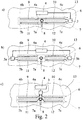
- FIG. 1 and 2 A synopsis of Fig. 1 and 2 shows that when installed control system, a vehicle component 8, here a trailer hitch 8, is arranged or arrangeable in the sensor extension.
- vehicle component 8 here the trailer hitch
- rangeable is meant that the vehicle component 8, here the trailer hitch, usually lose weight.
- Other vehicle components are conceivable in this context. Examples are bike carriers, exhaust systems o. The like ..
- Fig. 2 suggests that with a specific design of the at least one distance sensor 6, 7, the vehicle component 8 would be detected by the distance sensor 6, 7, which would disturb the sensory detection of the distance a to a user B. This would be the case in particular if the distance sensor 6, 7 would extend homogeneously over the entire vehicle width.
- the at least one distance sensor 6, 7 is designed such that it has a blind section 6a, 7a in the area of the vehicle component 8, which does not have any sensitivity. This is realized by an interruption of the distance sensor 6, 7 in the region of the vehicle component 8, as will be explained. In principle, however, it is also conceivable that the blind section 6a, 7a has a lower sensitivity compared to the area of the distance sensor 6, 7 adjoining the blind section 6a, 7a, as will also be explained. In any case, the disturbing influence of the vehicle component 8 is reduced to the sensor operation.
- the at least one distance sensor 6, 7 is designed such that it has a blind section 6a, 7a associated with the vehicle component 8 and thus the vehicle component 8 can not be detected by the distance sensor 6, 7. Accordingly, the vehicle component 8 can also cause no disturbance of the sensory detection of the distance a to a user B.
- the blind portion 6a, 7a ensures that the disturbing influence of the vehicle component 8 is suppressed to a certain extent on the respective measurement result.
- the statements "non-detectable" and “no disturbance” are in this case not in an ideal sense with regard to the relatively rough measuring conditions, but rather that in this variant the vehicle component 8 has no appreciable effect on the sensor operation due to the blind section.
- the illustrated embodiment of the distance sensor 6, 7 as a capacitive sensor has proven itself in practice. However, it can also be advantageous to use an inductive sensor. In principle, other sensor principles are applicable. It is conceivable, for example, that the distance sensor 6, 7 is a magnetic sensor.
- the capacitive distance sensor 6, 7 is an elongated measuring electrode 9, 10; 11, 12 associated, which extends along the respective sensor extension.
- Fig. 2 shows that the blind portion 6a, 7a here and preferably as an interruption of the distance sensor 6, 7 is configured.
- the extent of the blind section 6a, 7a along the sensor extension is at least 5%, and in particular at least 10% of the total length of the distance sensor 6,
- blind portion 6a, 7a a much larger extension of the blind portion 6a, 7a is conceivable, for example, if it is the case of the relevant vehicle component 8 is a bicycle rack o. The like.
- the design, in particular the extent of the blind section 6a, 7a, as indicated above, is preferably such that the influence of the relevant vehicle component 8 on the measurement result is no longer appreciable.
- the blind section 6a, 7a has a shield which shields the region of the vehicle component 8 with respect to the sensory detection.
- This can be provided for example by a kind of metal screen, a metallic sheathing or the like.
- the blind portion 6a, 7a is an above interruption of the distance sensor 6, 7 along the sensor extension, so that on both sides of the vehicle component 8, a sensor module 6b, 6c; 7b, 7c is arranged.
- the sensor modules 6b, 6c, 7b, 7c are each assigned a measuring electrode 9, 10, 11, 12 which follow the illustration in FIG Fig. 2 can be removed.
- the control of the sensor modules 6b, 6c, 7b, 7c is of particular importance in the present case.
- the sensor modules 6b, 6b arranged on both sides of the vehicle component 8 are; 7b, 7c of a distance sensor 6, 7 electrically contacted with each other.
- the two distance sensors 6, 7 associated with a common sensor control 3, which allows either a parallel control of the two distance sensors 6, 7 or an alternating control of the two distance sensors 6, 7.
- the sensor modules 6b, 6c, 7b, 7c of a distance sensor 6, 7 arranged on both sides of the vehicle component 8 are each assigned a separate sensor control.
- each measuring electrode 9, 10, 11, 12 may be assigned its own sensor control 3.
- the sensor modules 6b arranged on both sides of the vehicle component 8, 6c; 7b, 7c of a distance sensor 6, 7 a common sensor control 3 is assigned.
- the measuring electrodes 9, 10, 11, 12 may be electrically connected at least in part via plug-in connections before the connection to the sensor control 3 takes place. It is also conceivable, as shown in the drawing, that each measuring electrode 9, 10, 11, 12 is individually connected to the respective sensor control 3.
- the distance sensors 6, 7 are not homogeneous along their sensor extension, but have been provided with the blind portion 6a, 7a, affects a user longitudinal movement along the sensor extension on the measurement results. This can be used in the detection of the operating events, as will be explained.
- the motor vehicle shown is equipped with a body component 13, which may be, for example, a front / rear or side skirt.
- the distance sensors 6, 7 are arranged in the mounted state in or behind the body component 13. In the case of the body component 13 designed here as a rear apron, the distance sensor 6, 7 preferably extends at least over the essential width of the body component 13.
- the proposed solution can be applied to all types of closure elements 1. Also, the proposed solution can capture all types of user movement.
- a motor vehicle with a motor-driven closure element 1, in particular with a motorized tailgate, a motorized side door, a motorized sliding door o.
- a motorized tailgate which is equipped with a proposed control system for controlling the motor-driven closure element 1. All statements on the proposed tax system may be referred to.
- a method for the operation of the proposed control system is claimed. What is essential in the method is that a user longitudinal movement along the sensor extension of the at least one distance sensor 6, 7 through the blind portion 6a, 7a results in a pattern in the temporal sensor signal course, which is detected by the control system at least as part of an operating event.
- the user longitudinal movement leads to a jump signal change as soon as the user passes the vehicle component 8.
- This sudden change has a certain characteristic, which is taken into account during the recording of operating events.
Landscapes
- Physics & Mathematics (AREA)
- General Physics & Mathematics (AREA)
- Engineering & Computer Science (AREA)
- Computer Networks & Wireless Communication (AREA)
- Mechanical Engineering (AREA)
- Power-Operated Mechanisms For Wings (AREA)
- Measurement Of Length, Angles, Or The Like Using Electric Or Magnetic Means (AREA)
Description
- Die Erfindung betrifft ein Steuersystem zur Ansteuerung eines motorischen Verschlusselements eines Kraftfahrzeugs gemäß dem Oberbegriff von Anspruch 1, ein Kraftfahrzeug mit einem solchen Steuersystem gemäß Anspruch 11 sowie ein Verfahren für den Betrieb eines solchen Steuersystems gemäß Anspruch 12.
- Die heutigen Kraftfahrzeuge sind zunehmend mit motorisch betätigbaren Verschlusselementen ausgestattet. Bei solchen Verschlusselementen kann es sich beispielsweise um Türen wie Seiten- und Hecktüren, insbesondere Schiebetüren, Klappen, insbesondere Heckklappen, Heckdeckel, Motorhauben, Laderaumböden o. dgl. eines Kraftfahrzeugs handeln. Insoweit ist der Begriff "Verschlusselement" vorliegend weit zu verstehen.
- Eine Komfortfunktion, der heute zunehmende Bedeutung zukommt, ist die automatische Betätigung der motorischen Heckklappe eines Kraftfahrzeugs. Bei dem bekannten Steuersystem (
DE 20 2005 020 140 U1 ), von dem die Erfindung ausgeht, ist es vorgesehen, dass ein bedienerseitiges Bedienereignis, hier eine bedienerseitige Fußbewegung, das motorische Öffnen der Heckklappe bewirkt. - Hierfür sind eine der Heckklappe zugeordnete Antriebsanordnung, eine Sensorsteuerung sowie ein Abstandssensor vorgesehen. Die Sensorsteuerung überwacht die Sensorsignale daraufliin, ob das obige Bedienereignis vorliegt. In Abhängigkeit vom Ergebnis dieser Bedienereignisüberwachung wird entsprechend eine Ansteuerung der Antriebsanordnung vorgenommen.
- Zur Erfassung der obigen Bedienereignisse können kapazitive Abstandssensoren Einsatz finden, die mit mindestens einer Messelektrode ausgestattet sind. Ein Bedienereignis löst hier eine Kapazitätsänderung der Elektrodenanordnung aus, die sich leicht elektronisch erfassen lässt. Eine solche Messelektrode ist regelmäßig in die Heckschürze eines Kraftfahrzeugs integriert und erstreckt sich über die gesamte Breite des Kraftfahrzeugs.
-
DE 10 2010 002 559 A1 offenbart ein Steuersystem zur Ansteuerung eines motorischen Verschlusselements eines Kraftfahrzeugs mit einem länglichen Abstandssensor, der Bereiche mit wechselnder Erfassungssensitivität aufweist. Schwierigkeiten können sich ergeben, wenn Kraftfahrzeugkomponenten, insbesondere Anbauteile, die sensorische Erfassung der Bedienereignisse stören oder der Messelektrode schlicht im Weg sind. Bei solchen Kraftfahrzeugkomponenten kann es sich um Anhängerkupplungen, Fahrradständer, Abgasanlagen o. dgl. handeln. - Der Erfindung liegt das Problem zugrunde, das bekannte Steuersystem derart auszugestalten und weiterzubilden, dass eine eventuelle Störung der sensorischen Erfassung von Bedienereignissen durch bestimmte Fahrzeugkomponenten vermieden wird.
- Das obige Problem wird bei einem Steuersystem gemäß dem Oberbegriff von Anspruch 1 durch die Merkmale des kennzeichnenden Teils von Anspruch 1 gelöst.
- Vorschlagsgemäß ist erkannt worden, dass der mindestens eine Abstandssensor des Steuersystems konstruktiv so ausgelegt werden kann, dass sein Sensorbetrieb durch die an sich störende Fahrzeugkomponente nicht oder nur geringfügig beeinträchtigt wird.
- Im Einzelnen weist der Abstandssensor im Bereich der Fahrzeugkomponente einen Blindabschnitt auf, der keine Sensitivität oder verglichen mit dem an den Blindabschnitt angrenzenden Bereich des Abstandssensors eine geringere Sensitivität aufweist.
- Der Begriff "Sensitivität" ist hier in einem erweiterten Sinne derart zu verstehen, dass eine Änderung der Sensitivität bei identischem Abstand zu dem Benutzer stets eine entsprechende Änderung des Sensorsignals mit sich bringt. Die Formulierung "keine Sensitivität" bedeutet im obigen Sinne, dass im Blindabschnitt überhaupt keine sensorische Erfassung stattfindet.
- Der Begriff "Blindabschnitt" ist ebenfalls in einem erweiterten Sinne zu verstehen. Er umfasst wie oben angedeutet nicht nur einen Abschnitt ganz ohne Sensitivität, also ohne sensorische Erfassung, sondern auch einen Abschnitt mit vergleichsweise geringer Sensitivität.
- Die vorschlagsgemäße Lösung gewährleistet eine hohe Robustheit gegenüber einer eventuellen Sensorstörung durch die betreffende Fahrzeugkomponente und lässt sich auf denkbar einfache Weise realisieren.
- Vorschlagsgemäß ist der Abstandssensor mit einem der Fahrzeugkomponente zugeordneten Blindabschnitt ausgestattet, der so ausgelegt ist, dass die Fahrzeugkomponente durch den Abstandssensor nicht erfassbar ist und entsprechend keine Störung der sensorischen Erfassung des Abstands zu einem Benutzer verursacht.
- Bei der weiter bevorzugten Ausgestaltung gemäß Anspruch 5 ist es so, dass der Blindabschnitt eine den Bereich der Fahrzeugkomponente im Hinblick auf die sensorische Erfassung abschirmende Abschirmung aufweist. Eine solche Abschirmung kann grundsätzlich die obige Reduzierung der Sensitivität bewirken.
- In besonders bevorzugter und konstruktiv leicht zu realisierender Ausgestaltung wird gemäß Anspruch 6 vorgeschlagen, dass der Blindabschnitt eine Unterbrechung des Abstandssensors entlang der Sensorerstreckung ist, so dass beidseits der Fahrzeugkomponente ein Sensormodul angeordnet ist. Diese Unterbrechung des Abstandssensors ist insofern besonders vorteilhaft, als die Fahrzeugkomponente ohne weiteres innerhalb des Blindabschnitts untergebracht werden kann, ohne dass sich konstruktive Überschneidungen zwischen Fahrzeugkomponente und Abstandssensor ergeben.
- Nach einer weiteren Lehre gemäß Anspruch 11, der eigenständige Bedeutung zukommt, wird ein Kraftfahrzeug mit einem motorischen Verschlusselement, vorzugsweise mit einer motorischen Heckklappe, einer motorischen Seitentür, einer motorischen Schiebetür o. dgl., beansprucht, das mit einem obigen, vorschlagsgemäßen Steuersystem ausgestattet ist. Auf alle Ausführungen, die geeignet sind, das vorschlagsgemäße Kraftfahrzeug zu beschreiben, darf verwiesen werden.
- Nach einer weiteren Lehre gemäß Anspruch 12, der ebenfalls eigenständige Bedeutung zukommt, wird ein Verfahren für den Betrieb eines vorschlagsgemäßen Steuersystems beansprucht.
- Wesentlich nach dieser weiteren Lehre ist, dass eine Benutzer-Längsbewegung entlang der Sensorerstreckung des mindestens eines Abstandssensors durch dessen Blindabschnitt ein Muster im zeitlichen Sensorsignalverlauf ergibt, das von dem Steuersystem zumindest als Teil eines Bedienereignisses erfasst wird. Im Einzelnen lässt sich dann nicht nur ein Abstand zu einem Benutzer, sondern eine Bewegungsrichtung des Benutzers entlang der Sensorerstreckung, erfassen. Insoweit darf auf alle Ausführungen zu dem vorschlagsgemäßen Steuersystem verwiesen werden.
- Im Folgenden wird die Erfindung anhand einer lediglich ein Ausführungsbeispiel darstellenden Zeichnung näher erläutert. In der Zeichnung zeigt
- Fig. 1
- den Heckbereich eines Kraftfahrzeugs mit einem vorschlagsgemäßen Steuersystem zur Durchführung des vorschlagsgemäßen Verfahrens und
- Fig. 2
- in ganz schematischer Darstellung die Heckschürze des Heckbereichs gemäß
Fig. 1 in einer stirnseitigen Ansicht a) mit einem ersten vorschlagsgemäßen Steuersystem, b) mit einem zweiten vorschlagsgemäßen Steuersystem und c) mit einem dritten vorschlagsgemäßen Steuersystem. - Das vorschlagsgemäße Steuersystem wird im Folgenden anhand eines motorischen Verschlusselements 1 eines Kraftfahrzeugs erläutert, das als Heckklappe ausgestaltet ist.
- Die Ausgestaltung des Verschlusselements 1 als Heckklappe eines Kraftfahrzeugs ist vorliegend bevorzugt. Allerdings darf im Hinblick auf das weite Verständnis des Begriffs "Verschlusselement" auf den einleitenden Teil der Beschreibung verwiesen werden. Insoweit gelten alle Ausführungen zu einer Heckklappe 1 entsprechend für alle anderen Arten von Verschlusselementen.
- Der Heckklappe 1 ist eine Antriebsanordnung 2 zugeordnet, mittels der eine motorische Verstellung der Heckklappe 1 zwischen der in
Fig. 1 in durchgezogener Linie dargestellten Schließstellung und der inFig. 1 in gestrichelter Linie dargestellten Offenstellung bewirkbar ist. - Es ist ferner mindestens eine Sensorsteuerung 3 vorgesehen, die der Erfassung von Bedienereignissen und darauf basierend der Ansteuerung der motorischen Heckklappe 1 dient. Hier und vorzugsweise ist der mindestens einen Sensorsteuerung 3 ein übergeordnetes Heckklappensteuergerät 4 zugeordnet, das über ein Bussystem 5 mit einer zentralen Fahrzeugsteuerung o. dgl. kommuniziert. Vorzugsweise erfolgt die eigentliche Extraktion von Bedienereignissen aus den Sensorsignalen, insbesondere eine entsprechende Mustererkennung, in dem Heckklappensteuergerät 4. Denkbar ist aber auch, dass dies zumindest teilweise, insbesondere im Sinne einer Signal-Vorverarbeitung, in der mindestens einen Sensorsteuerung 3 erfolgt.
- Die auszuwertenden Sensorsignale gehen zurück auf mindestens einen länglichen Abstandssensor 6, 7, hier auf genau zwei längliche, parallel zueinander verlaufende Abstandssensoren 6, 7, die sich jeweils entlang einer Sensorerstreckung erstrecken. Die Sensorerstreckung kann gerade, gebogen, kreisförmig o. dgl. sein.
- Hier und vorzugsweise sind genau zwei Abstandssensoren 6, 7 vorgesehen, die sich wie oben angedeutet im Wesentlichen parallel zueinander erstrecken. Grundsätzlich ist es auch denkbar, dass mehr als zwei längliche Abstandssensoren 6, 7 vorgesehen sind. Vorliegend ist stellenweise von nur einem einzigen Abstandssensor 6, 7 die Rede, was der Vereinfachung dienen soll. Alle diesbezüglichen Ausführungen gelten für den jeweils zweiten Abstandssensor 6, 7 entsprechend.
- Der mindestens einen Sensorsteuerung 3 kommt wie oben angedeutet, die Aufgabe zu, den zugeordneten Abstandssensor 6, 7 anzusteuern und/oder dessen Sensorsignale auszuwerten. Der mindestens eine Abstandssensor 6, 7 ist so ausgelegt, dass sich mit ihm ein Abstand a zu einem Benutzer B erfassen lässt.
- Eine Zusammenschau der
Fig. 1 und2 zeigt, dass bei installiertem Steuersystem eine Fahrzeugkomponente 8, hier eine Anhängerkupplung 8, in der Sensorerstreckung angeordnet bzw. anordnenbar ist. Mit "anordnenbar" ist gemeint, dass sich die Fahrzeugkomponente 8, hier die Anhängerkupplung, in der Regel abnehmen lässt. Andere Fahrzeugkomponenten sind in diesem Zusammenhang denkbar. Beispiele hierfür sind Fahrradträger, Abgasanlagen o. dgl.. -
Fig. 2 lässt vermuten, dass bei bestimmter Auslegung des mindestens einen Abstandssensors 6, 7 die Fahrzeugkomponente 8 durch den Abstandssensor 6, 7 erfassbar wäre, was die sensorische Erfassung des Abstands a zu einem Benutzer B stören würde. Dies wäre insbesondere der Fall, wenn sich der Abstandssensor 6, 7 homogen über die gesamte Fahrzeugbreite erstrecken würde. - Hier und vorzugsweise ist der mindestens eine Abstandssensor 6, 7 jedoch so ausgelegt, dass er im Bereich der Fahrzeugkomponente 8 einen Blindabschnitt 6a, 7a aufweist, der keine Sensitivität aufweist. Dies ist durch eine Unterbrechung des Abstandssensors 6, 7 im Bereich der Fahrzeugkomponente 8 realisiert, wie noch erläutert wird. Grundsätzlich ist es aber auch denkbar, dass der Blindabschnitt 6a, 7a verglichen mit dem an den Blindabschnitt 6a, 7a angrenzenden Bereich des Abstandssensors 6, 7 eine geringere Sensitivität aufweist, wie ebenfalls noch erläutert wird. In jedem Fall wird damit der störende Einfluss der Fahrzeugkomponente 8 auf den Sensorbetrieb reduziert.
- In einer bevorzugten Variante ist der mindestens eine Abstandssensor 6, 7 so ausgelegt, dass er einen der Fahrzeugkomponente 8 zugeordneten Blindabschnitt 6a, 7a aufweist und dadurch die Fahrzeugkomponente 8 durch den Abstandssensor 6, 7 nicht erfassbar ist. Entsprechend kann die Fahrzeugkomponente 8 auch keine Störung der sensorischen Erfassung des Abstands a zu einem Benutzer B verursachen. Der Blindabschnitt 6a, 7a sorgt dafür, dass der störende Einfluss der Fahrzeugkomponente 8 auf das jeweilige Meßergebnis gewissermaßen ausgeblendet wird. Die Angaben "nicht erfassbar" und "keine Störung" sind vorliegend im Hinblick auf die relativ rauhen Meßbedingungen nicht in einem idealen Sinne, sondern so zu verstehen, dass bei dieser Variante die Fahrzeugkomponente 8 durch den Blindabschnitt keine spürbare Auswirkung auf den Sensorbetrieb hat.
- Die dargestellte Ausgestaltung des Abstandssensors 6, 7 als kapazitiver Sensor hat sich in der Praxis bewährt. Vorteilhaft kann aber auch die Anwendung eines induktiven Sensors sein. Grundsätzlich sind auch andere Sensorprinzipien anwendbar. Denkbar ist beispielsweise, dass es sich bei dem Abstandssensor 6, 7 um einen magnetischen Sensor handelt.
- Dem kapazitiven Abstandssensor 6, 7 ist eine längliche Messelektrode 9, 10; 11, 12 zugeordnet, die sich entlang der jeweiligen Sensorerstreckung erstreckt.
-
Fig. 2 zeigt, dass der Blindabschnitt 6a, 7a hier und vorzugsweise als Unterbrechung des Abstandssensors 6, 7 ausgestaltet ist. Ganz allgemein beträgt die Ausdehnung des Blindabschnitts 6a, 7a entlang der Sensorerstreckung mindestens 5 %, und insbesondere mindestens 10 % der Gesamtlänge des Abstandssensors 6, - 7. Grundsätzlich ist eine weitaus größere Ausdehnung des Blindabschnitts 6a, 7a denkbar, beispielsweise, wenn es sich bei der betreffenden Fahrzeugkomponente 8 um einen Fahrradträger o. dgl. handelt. Die Auslegung, insbesondere die Ausdehnung des Blindabschnitts 6a, 7a ist wie weiter oben angedeutet vorzugsweise so getroffen, dass der Einfluss der betreffenden Fahrzeugkomponente 8 auf das Messergebnis nicht mehr nennenswert ist.
- Bei einer einfach zu realisierenden Ausgestaltung weist der Blindabschnitt 6a, 7a eine den Bereich der Fahrzeugkomponente 8 im Hinblick auf die sensorische Erfassung abschirmende Abschirmung auf. Dies kann beispielsweise durch eine Art Metallschirm, eine metallische Ummantelung o. dgl. vorgesehen sein.
- In besonders bevorzugter Ausgestaltung ist es allerdings so, dass der Blindabschnitt 6a, 7a eine obige Unterbrechung des Abstandssensors 6, 7 entlang der Sensorerstreckung ist, so dass beidseits der Fahrzeugkomponente 8 ein Sensormodul 6b, 6c; 7b, 7c angeordnet ist. Den Sensormodulen 6b, 6c, 7b, 7c sind jeweils eine Messelektrode 9, 10, 11, 12 zugeordnet, die sich der Darstellung gemäß
Fig. 2 entnehmen lässt. - Der Ansteuerung der Sensormodule 6b, 6c, 7b, 7c kommt vorliegend ganz besondere Bedeutung zu.
- In einer besonders einfachen Variante sind die beidseits der Fahrzeugkomponente 8 angeordneten Sensormodule 6b, 6b; 7b, 7c eines Abstandssensors 6, 7 elektrisch miteinander kontaktiert. Dies bedeutet, dass die Messelektroden 9, 10 und die Messelektroden 11, 12 elektrisch miteinander kontaktiert sind, wie der Darstellung gemäß
Fig. 2a ) zu entnehmen ist. Dabei ist den beiden Abstandssensoren 6, 7 eine gemeinsame Sensorsteuerung 3 zugeordnet, die entweder eine parallele Ansteuerung der beiden Abstandssensoren 6, 7 oder eine abwechselnde Ansteuerung der beiden Abstandssensoren 6, 7 ermöglicht. - Denkbar ist aber auch, dass den beidseits der Fahrzeugkomponente 8 angeordneten Sensormodulen 6b, 6c, 7b, 7c eines Abstandssensors 6, 7 jeweils eine separate Sensorsteuerung zugeordnet ist. Beispielsweise kann jeder Messelektrode 9, 10, 11, 12 eine eigene Sensorsteuerung 3 zugeordnet sein. Denkbar ist aber auch, dass den beidseits der Fahrzeugkomponente 8 angeordneten Sensormodulen 6b, 6c; 7b, 7c eines Abstandssensors 6, 7 eine gemeinsame Sensorsteuerung 3 zugeordnet ist.
- Bei der in
Fig. 2b ) dargestellten und insoweit bevorzugten Ausgestaltung ist den auf einer Seite der Fahrzeugkomponente 8 angeordneten Sensormodulen 6b, 7b, 6c, 7c der mindestens zwei Abstandssensoren 6, 7 eine gemeinsame Sensorsteuerung 3a, 3b zugeordnet. - Denkbar ist schließlich, dass alle Messelektroden, 9, 10, 11, 12 der Abstandssensoren 6, 7 separat an eine Sensorsteuerung 3 angeschlossen sind. Das ist in
Fig. 2c ) dargestellt. - Je nach Steuerungsstruktur können die Messelektroden 9, 10, 11, 12 zumindest zum Teil über Steckverbindungen elektrisch verbunden sein, bevor der Anschluss an die Sensorsteuerung 3 erfolgt. Denkbar ist auch, wie in der Zeichnung dargestellt, dass jede Messelektrode 9, 10, 11, 12 einzeln an die jeweilige Sensorsteuerung 3 angeschlossen ist.
- Dadurch, dass die Abstandssensoren 6, 7 entlang deren Sensorerstreckung nicht homogen sind, sondern mit dem Blindabschnitt 6a, 7a, versehen worden sind, wirkt sich eine Benutzer-Längsbewegung entlang der Sensorerstreckung auf die Messergebnisse aus. Dies lässt sich bei der Erfassung der Bedienereignisse nutzen, wie noch erläutert wird.
- Das dargestellte Kraftfahrzeug ist mit einem Karosseriebauteil 13 ausgestattet, bei dem es sich beispielsweise um eine Front-/Heck- oder Seitenschürze handeln kann. Die Abstandssensoren 6, 7 sind im montierten Zustand in oder hinter dem Karosseriebauteil 13 angeordnet. Bei dem hier dargestellten, als Heckschürze ausgestalteten Karosseriebauteil 13 erstreckt sich der Abstandssensor 6, 7 vorzugsweise mindestens über die wesentliche Breite des Karosseriebauteils 13.
- Wie oben erläutert, kann die vorschlagsgemäße Lösung auf alle Arten von Verschlusselementen 1 angewendet werden. Auch können mit der vorschlagsgemäßen Lösung alle Arten von Benutzerbewegungen erfasst werden.
- Nach einer weiteren Lehre, der eigenständige Bedeutung zukommt, wird ein Kraftfahrzeug mit einem motorischen Verschlusselement 1, insbesondere mit einer motorischen Heckklappe, einer motorischen Seitentür, einer motorischen Schiebetür o. dgl. beansprucht, das mit einem vorschlagsgemäßen Steuersystem zur Ansteuerung des motorischen Verschlusselements 1 ausgestattet ist. Auf alle Ausführungen zu dem vorschlagsgemäßen Steuersystem darf verwiesen werden.
- Nach einer weiteren Lehre, der ebenfalls eigenständige Bedeutung zukommt, wird ein Verfahren für den Betrieb des vorschlagsgemäßen Steuersystems beansprucht. Wesentlich bei dem Verfahren ist, dass eine Benutzer-Längsbewegung entlang der Sensorerstreckung des mindestens einen Abstandssensors 6, 7 durch dessen Blindabschnitt 6a, 7a ein Muster im zeitlichen Sensorsignalverlauf ergibt, das von dem Steuersystem zumindest als Teil eines Bedienereignisses erfasst wird.
- In einer bevorzugten Variante, die sich am besten mit der Ausgestaltung gemäß
Fig. 2a ) realisieren lässt, führt die Benutzer-Längsbewegung zu einer sprunghaf ten Signaländerung, sobald der Benutzer die Fahrzeugkomponente 8 passiert. Dieser sprunghaften Änderung kommt eine gewisse Charakteristik zu, die im Rahmen der Erfassung von Bedienereignissen berücksichtigt wird. - Die weiter bevorzugten Varianten gemäß
Fig. 2b ) und c) ermöglichen es sogar, eine Bewegungsrichtung in der Benutzer-Längsbewegung zu erkennen, da die jeweiligen Messelektroden 9, 10, 11, 12 zumindest zum Teil separat angesteuert werden. Die Bewegungsrichtung in der Benutzer-Längsbewegung lässt sich ebenfalls vorteilhaft bei der Erfassung von Bedienereignissen nutzen.
Claims (12)
- Steuersystem zur Ansteuerung eines motorischen Verschlusselements (1) eines Kraftfahrzeugs, wobei zur Erfassung von Bedienereignissen mindestens eine Sensorsteuerung (3) und mindestens ein länglicher, sich entlang einer Sensorerstreckung erstreckender Abstandssensor (6, 7) vorgesehen sind, wobei die Sensorsteuerung (3) den zugeordneten Abstandssensor (6, 7) ansteuert und/oder dessen Sensorsignale auswertet und wobei der Abstandssensor (6, 7) einen Abstand (a) zu einem Benutzer (B) erfasst,
dadurch gekennzeichnet,
dass bei installiertem Steuersystem eine Fahrzeugkomponente (8) in oder entlang der Sensorerstreckung, insbesondere eine Anhängerkupplung o. dgl., angeordnet oder anordenbar ist, dass der Abstandssensor (6, 7) so ausgelegt ist, dass er im Bereich der Fahrzeugkomponente (8) einen Blindabschnitt (6a, 7a) aufweist, der keine Sensitivität oder verglichen mit dem an den Blindabschnitt (6a, 7a) angrenzenden Bereich des Abstandssensors (6, 7) eine geringere Sensitivität auf weist und dass wegen des Blindabschnitts (6a, 7a) die Fahrzeugkomponente (8) durch den Abstandssensor (6, 7) nicht erfassbar ist und keine Störung der sensorischen Erfassung des Abstands (a) zu einem Benutzer (B) verursacht. - Steuersystem nach Anspruch 1, dadurch gekennzeichnet, dass mindestens zwei längliche Abstandssensoren (6, 7) vorgesehen sind, die sich im Wesentlichen parallel zueinander erstrecken.
- Steuersytem nach einem der vorhergehenden Ansprüche, dadurch gekennzeichnet, dass der mindestens eine Abstandssensor (6, 7) als kapazitiver Sensor mit einer länglichen Meßelektrode (9-12) ausgestaltet ist.
- Steuersystem nach einem der vorhergehenden Ansprüche, dadurch gekennzeichnet, dass die Ausdehnung des Blindabschnitts (6a, 7a) entlang der Sensorerstreckung mindestens 5%, vorzugsweise mindestens 10% der Gesamtlänge des Abstandssensors (6, 7) beträgt.
- Steuersystem nach einem der vorhergehenden Ansprüche, dadurch gekennzeichnet, dass der Blindabschnitt (6a, 7b) eine den Bereich der Fahrzeugkomponente (8) im Hinblick auf die sensorische Erfassung abschirmende Abschirmung aufweist.
- Steuersystem nach einem der vorhergehenden Ansprüche, dadurch gekennzeichnet, dass der Blindabschnitt (6a, 7a) eine Unterbrechung des Abstandssensors (6, 7) entlang der Sensorerstreckung ist, so dass beidseits der Fahrzeugkomponente (8) ein Sensormodul (6b, 6c, 7b, 7c) angeordnet ist.
- Steuersystem nach einem der vorhergehenden Ansprüche, dadurch gekennzeichnet, dass die beidseits der Fahrzeugkomponente (8) angeordneten Sensormodule (6b, 6c, 7b, 7c) eines Abstandssensors (6, 7) elektrisch miteinander kontaktiert sind.
- Steuersystem nach einem der vorhergehenden Ansprüche, dadurch gekennzeichnet, dass den beidseits der Fahrzeugkomponente (8) angeordneten Sensormodulen (6b, 6c, 7b, 7c) eines Abstandssensors (6, 7) jeweils eine separate Sensorsteuerung (3) zugeordnet ist, oder, dass den beidseits der Fahrzeugkomponente (8) angeordneten Sensormodulen (6b, 6c, 7b, 7c) eines Abstandssensors eine gemeinsame Sensorsteuerung (3) zugeordnet ist.
- Steuersystem nach Anspruch 2 und ggf. nach einem der Ansprüche 3 bis 8, dadurch gekennzeichnet, dass den auf einer Seite der Fahrzeugkomponente angeordneten Sensormodulen (6b, 7b; 6c, 7c) der mindestens zwei Abstandssensoren (6, 7) eine gemeinsame Sensorsteuerung (3a, 3b) zugeordnet ist.
- Steuersystem nach einem der vorhergehenden Ansprüche, dadurch gekennzeichnet, dass der Abstandssensor (6, 7) in oder an einem Karosseriebauteil (13), insbesondere in oder an einer Front-, Heck oder Seitenschürze anordenbar ist, vorzugsweise, dass der Abstandssensor (6, 7) mindestens über die wesentlichen Breite des Karosseriebauteils (13) erstreckbar ist.
- Kraftfahrzeug mit einem motorischen Verschlusselement (1), insbesondere mit einer motorischen Heckklappe, einer motorischen Seitentür, einer motorischen Schiebetür o. dgl., und mit einem Steuersystem zur Ansteuerung des motorischen Verschlusselements (1) nach einem der vorhergehenden Ansprüche.
- Verfahren für den Betrieb eines Steuersystems nach einem der Ansprüche 1 bis 10, wobei eine Benutzer-Längsbewegung entlang der Sensorerstreckung des mindestens einen Abstandssensors (6, 7) durch dessen Blindabschnitt (6a, 7a) ein Muster im zeitlichen Sensorsignalverlauf ergibt, das von dem Steuersystem zumindest als Teil eines Bedienereignisses erfasst wird.
Priority Applications (1)
| Application Number | Priority Date | Filing Date | Title |
|---|---|---|---|
| EP17161057.9A EP3211363B8 (de) | 2011-12-21 | 2012-12-18 | Steuersystem zur ansteuerung eines motorischen verschlusselements eines kraftfahrzeugs und entsprechendes betriebsverfahren |
Applications Claiming Priority (2)
| Application Number | Priority Date | Filing Date | Title |
|---|---|---|---|
| DE102011121775A DE102011121775B3 (de) | 2011-12-21 | 2011-12-21 | Steuersystem |
| PCT/EP2012/005234 WO2013091839A2 (de) | 2011-12-21 | 2012-12-18 | Steuersystem |
Related Child Applications (2)
| Application Number | Title | Priority Date | Filing Date |
|---|---|---|---|
| EP17161057.9A Division EP3211363B8 (de) | 2011-12-21 | 2012-12-18 | Steuersystem zur ansteuerung eines motorischen verschlusselements eines kraftfahrzeugs und entsprechendes betriebsverfahren |
| EP17161057.9A Division-Into EP3211363B8 (de) | 2011-12-21 | 2012-12-18 | Steuersystem zur ansteuerung eines motorischen verschlusselements eines kraftfahrzeugs und entsprechendes betriebsverfahren |
Publications (2)
| Publication Number | Publication Date |
|---|---|
| EP2795240A2 EP2795240A2 (de) | 2014-10-29 |
| EP2795240B1 true EP2795240B1 (de) | 2017-06-28 |
Family
ID=47503361
Family Applications (2)
| Application Number | Title | Priority Date | Filing Date |
|---|---|---|---|
| EP12826643.4A Not-in-force EP2795240B1 (de) | 2011-12-21 | 2012-12-18 | Steuersystem zur ansteuerung eines motorischen verschlusselements eines kraftfahrzeugs |
| EP17161057.9A Active EP3211363B8 (de) | 2011-12-21 | 2012-12-18 | Steuersystem zur ansteuerung eines motorischen verschlusselements eines kraftfahrzeugs und entsprechendes betriebsverfahren |
Family Applications After (1)
| Application Number | Title | Priority Date | Filing Date |
|---|---|---|---|
| EP17161057.9A Active EP3211363B8 (de) | 2011-12-21 | 2012-12-18 | Steuersystem zur ansteuerung eines motorischen verschlusselements eines kraftfahrzeugs und entsprechendes betriebsverfahren |
Country Status (6)
| Country | Link |
|---|---|
| US (2) | US10563447B2 (de) |
| EP (2) | EP2795240B1 (de) |
| KR (1) | KR101657386B1 (de) |
| CN (1) | CN104246423B (de) |
| DE (1) | DE102011121775B3 (de) |
| WO (1) | WO2013091839A2 (de) |
Cited By (1)
| Publication number | Priority date | Publication date | Assignee | Title |
|---|---|---|---|---|
| CN115450526A (zh) * | 2022-08-11 | 2022-12-09 | 岚图汽车科技有限公司 | 一种尾门开启方法、系统、电子设备和计算机存储介质 |
Families Citing this family (23)
| Publication number | Priority date | Publication date | Assignee | Title |
|---|---|---|---|---|
| DE102011112274A1 (de) | 2011-09-05 | 2013-03-07 | Brose Fahrzeugteile Gmbh & Co. Kg, Hallstadt | Steuersystem |
| DE102011121775B3 (de) | 2011-12-21 | 2013-01-31 | Brose Fahrzeugteile Gmbh & Co. Kg, Hallstadt | Steuersystem |
| DE102012013065A1 (de) | 2012-07-02 | 2014-01-02 | Brose Fahrzeugteile Gmbh & Co. Kg, Hallstadt | Verfahren zur Ansteuerung einer Verschlusselementanordnung eines Kraftfahrzeugs |
| DE102013112418A1 (de) | 2013-11-12 | 2015-05-13 | Brose Fahrzeugteile Gmbh & Co. Kommanditgesellschaft, Hallstadt | Kapazitive Sensoranordnung eines Kraftfahrzeugs |
| DE102013114883A1 (de) | 2013-12-25 | 2015-06-25 | Brose Fahrzeugteile Gmbh & Co. Kommanditgesellschaft, Hallstadt | Steuersystem für eine motorische Verschlusselementanordnung eines Kraftfahrzeugs |
| DE102013114881A1 (de) | 2013-12-25 | 2015-06-25 | Brose Fahrzeugteile Gmbh & Co. Kommanditgesellschaft, Hallstadt | Steuersystem für eine motorische Verschlusselementanordnung eines Kraftfahrzeugs |
| DE102014117896A1 (de) | 2014-12-04 | 2016-06-23 | Brose Fahrzeugteile Gmbh & Co. Kg, Hallstadt | Verfahren zur Ansteuerung einer Schiebetüranordnung eines Kraftfahrzeugs |
| DE102014118318A1 (de) * | 2014-12-10 | 2016-06-16 | Valeo Schalter Und Sensoren Gmbh | Verfahren zum Erfassen eines Objekts in einem Öffnungsbereich einer Tür eines Kraftfahrzeugs, Fahrerassistenzsystem sowie Kraftfahrzeug |
| US9595144B2 (en) * | 2015-01-12 | 2017-03-14 | Honeywell International Inc. | Access monitor using wireless devices |
| DE102015112589A1 (de) | 2015-07-31 | 2017-02-02 | Brose Fahrzeugteile Gmbh & Co. Kommanditgesellschaft, Bamberg | Steuersystem für eine motorisch verstellbare Laderaumvorrichtung eines Kraftfahrzeugs |
| US10365753B2 (en) * | 2015-09-23 | 2019-07-30 | Vais Technology Ltd. | Hands-free power liftgate opener |
| DE102015119701A1 (de) | 2015-11-15 | 2017-05-18 | Brose Fahrzeugteile Gmbh & Co. Kommanditgesellschaft, Bamberg | Verfahren für den Betrieb einer kapazitiven Sensoranordnung eines Kraftfahrzeugs |
| JP6841164B2 (ja) * | 2017-05-30 | 2021-03-10 | アイシン精機株式会社 | 車両用非接触操作感知装置、及び静電容量センサ |
| KR102011197B1 (ko) * | 2017-06-20 | 2019-08-14 | 최준서 | 잠수함 탐지용 소나 |
| CN109693520B (zh) * | 2017-10-23 | 2021-01-12 | 宝沃汽车(中国)有限公司 | 追尾保护用尾门以及具有其的车辆 |
| DE102018110021B4 (de) * | 2018-04-26 | 2025-12-18 | Airbus Operations Gmbh | Vorrichtung zum Steuern einer Tür eines Transportmittels und Flugzeug |
| DE102019106853A1 (de) * | 2019-03-18 | 2020-09-24 | Brose Fahrzeugteile Se & Co. Kommanditgesellschaft, Bamberg | Steuersystem zur Ansteuerung einer Komfortfunktion eines Kraftfahrzeugs |
| JP7226091B2 (ja) * | 2019-05-22 | 2023-02-21 | 株式会社アイシン | センサブラケット |
| DE102019121280A1 (de) * | 2019-08-07 | 2021-02-11 | Kiekert Aktiengesellschaft | Verfahren und vorrichtung zum aufstellen eines kraftfahrzeugtürelements |
| US11847833B2 (en) | 2020-02-12 | 2023-12-19 | Strattec Security Corporation | Broad coverage non-contact obstacle detection |
| CN113086025B (zh) * | 2021-04-26 | 2022-04-15 | 长春捷翼汽车零部件有限公司 | 一种电动汽车的充电盖控制方法、设备及电动汽车 |
| US12466360B2 (en) * | 2023-07-18 | 2025-11-11 | Ford Global Technologies, Llc | Systems and methods for controlling vehicle rear closure |
| DE102023133967A1 (de) * | 2023-12-05 | 2025-06-05 | Brose Fahrzeugteile Se & Co. Kommanditgesellschaft, Bamberg | Verfahren zum Betrieb einer Verschlusselementanordnung eines Kraftfahrzeugs |
Family Cites Families (201)
| Publication number | Priority date | Publication date | Assignee | Title |
|---|---|---|---|---|
| US2127359A (en) * | 1936-11-24 | 1938-08-16 | Bertron G Harley | Coupling |
| JPS6018547B2 (ja) | 1977-05-13 | 1985-05-10 | 株式会社リコー | 静電記録針の電源スイツチ回路 |
| US4495330A (en) | 1983-05-25 | 1985-01-22 | General Electric Company | Crosslinkers for RTV compositions |
| US4595331A (en) | 1983-12-29 | 1986-06-17 | Adolph Coors Company | Automated railcar loader and method |
| US4867059A (en) | 1988-08-05 | 1989-09-19 | International Business Machines Corporation | Impact printer print mechanism and method of manufacture |
| US5394292A (en) | 1991-04-30 | 1995-02-28 | Tsuden Kabushiki Kaisha | Electronic car bumper |
| DE4133426A1 (de) | 1991-10-09 | 1993-04-15 | Bosch Gmbh Robert | Schaltungsanordnung zur auswertung und zum test eines kapazitiven sensors |
| DE4408468A1 (de) | 1994-03-12 | 1995-09-14 | Turck Werner Kg | Verfahren und Vorrichtung zur Individualisierung von galvanisch getrennten elektrisch leitfähigen Körpern |
| GB2295016A (en) | 1994-11-07 | 1996-05-15 | British Nuclear Fuels Plc | A transducer |
| DE9421122U1 (de) | 1994-11-10 | 1995-04-27 | Horst Siedle Kg, 78120 Furtwangen | Vorrichtung zur Bestimmung einer jeweiligen örtlichen Position eines Körpers |
| US5531498A (en) | 1994-12-01 | 1996-07-02 | Chrysler Corporation | Vehicle body with powered lift type tailgate |
| FR2740501B1 (fr) * | 1995-10-26 | 1998-06-19 | Valeo Securite Habitacle | Systeme mains libres de deverrouillage et/ou d'ouverture d'ouvrant de vehicule automobile |
| US6275146B1 (en) | 1996-04-23 | 2001-08-14 | Philip W. Kithil | Vehicle occupant sensing |
| WO1997039920A1 (en) | 1996-04-23 | 1997-10-30 | Advanced Safety Concepts, Inc. | Vehicle occupant sensing |
| US5844486A (en) | 1997-01-02 | 1998-12-01 | Advanced Safety Concepts, Inc. | Integral capacitive sensor array |
| FR2756990B1 (fr) | 1996-12-05 | 1999-06-11 | Schneider Electric Sa | Detecteur de proximite a amplificateur de reception rapide |
| US6535200B2 (en) | 1999-01-25 | 2003-03-18 | Harald Philipp | Capacitive position sensor |
| JP2001124861A (ja) | 1999-10-29 | 2001-05-11 | Nec Corp | 乗員検知システム及びアンテナ電極 |
| JP2001238761A (ja) | 2000-02-28 | 2001-09-04 | Johnson Controls Automotive Systems Corp | 車両用アームレスト構造 |
| US6337549B1 (en) | 2000-05-12 | 2002-01-08 | Anthony Gerald Bledin | Capacitive anti finger trap proximity sensor |
| US6323761B1 (en) | 2000-06-03 | 2001-11-27 | Sam Mog Son | Vehicular security access system |
| US20010054952A1 (en) | 2000-06-21 | 2001-12-27 | Desai Tejas B. | Automatic port operation |
| JP3754285B2 (ja) | 2000-09-27 | 2006-03-08 | 株式会社大井製作所 | ドアの自動開閉装置 |
| US6597284B2 (en) | 2000-11-29 | 2003-07-22 | Trw Inc. | Vehicle communication for tire sensor initiation and vehicle keyless entry via a shared resource |
| US6411054B1 (en) | 2000-12-15 | 2002-06-25 | Ford Global Technologies, Inc. | Obstruction detection system for power liftgate |
| US20020084675A1 (en) | 2000-12-28 | 2002-07-04 | Buchanan Harry Charles | Obstacle detection to the rear of a vehicle with a liftgate |
| DE10110493B4 (de) | 2001-03-05 | 2016-02-25 | Volkswagen Ag | Diebstahlsicherung von Kraftfahrzeugen |
| US6748308B2 (en) | 2001-03-30 | 2004-06-08 | Siemens Vdo Automotive Corporation | Automated closure system and method |
| DE10117935A1 (de) | 2001-04-10 | 2002-10-17 | Valeo Sicherheitssysteme Gmbh | Verfahren zum automatischen Betätigen einer Fahrzeugtür und Vorrichtung zur Durchführung dieses Verfahrens |
| US6719356B2 (en) | 2001-04-26 | 2004-04-13 | Litens Automotive | Powered opening mechanism and control system |
| US20030071738A1 (en) | 2001-05-10 | 2003-04-17 | Jean-Claude Joly | Seat occupancy sensor incorporated into a substrate and method of incorporating a wiring pattern into a substrate |
| GB2376075A (en) | 2001-06-01 | 2002-12-04 | Ab Automotive Electronics Ltd | Bumper proximity detector using capacitive sensor |
| US6946853B2 (en) | 2001-06-08 | 2005-09-20 | Intier Automotive Closures Inc. | Non-contact proximity sensor |
| US8225458B1 (en) | 2001-07-13 | 2012-07-24 | Hoffberg Steven M | Intelligent door restraint |
| JP3650375B2 (ja) | 2002-05-21 | 2005-05-18 | アイシン精機株式会社 | 車体用ドア装置 |
| DE10235925A1 (de) | 2002-08-06 | 2004-02-19 | Valeo Schalter Und Sensoren Gmbh | Fahrzeugumfeldüberwachungssystem und automatische Fahrzeugtüröffnungseinrichtung |
| US6774642B2 (en) | 2002-08-27 | 2004-08-10 | Delphi Technologies, Inc. | Capacitive angular position sensor |
| DE10254708A1 (de) | 2002-11-23 | 2004-06-03 | Adam Opel Ag | Verfahren zum fernbetätigten Öffnen bzw. Schließen einer heckseitigen Klappe eines Kraftfahrzeuges und Vorrichtung dazu |
| KR101046666B1 (ko) * | 2002-12-25 | 2011-07-06 | 에이씨티 엘에스아이 인크. | 정전 용량 검출형 근접 센서 |
| JP2004270142A (ja) | 2003-03-05 | 2004-09-30 | Mitsuba Corp | 車両用自動開閉装置 |
| US7343232B2 (en) | 2003-06-20 | 2008-03-11 | Geneva Aerospace | Vehicle control system including related methods and components |
| US20050114276A1 (en) | 2003-11-20 | 2005-05-26 | Hunter Valerie K. | Personal customization of stamps |
| DE102004008928A1 (de) | 2004-02-24 | 2005-09-08 | Bayerische Motoren Werke Ag | Verfahren zum Ankuppeln eines Anhängers unter Einsatz einer Fahrzeugniveauregulierung |
| FR2866612B1 (fr) | 2004-02-25 | 2006-05-05 | Renault Sas | Vehicule comportant un porte-charge |
| FR2868526B1 (fr) | 2004-04-06 | 2007-04-20 | Peugeot Citroen Automobiles Sa | Capteur de position d'un actionneur de soupape d'un moteur a combustion interne |
| JP4610300B2 (ja) | 2004-11-02 | 2011-01-12 | 富士通テン株式会社 | 車両用制御装置および車両用制御方法 |
| DE102004055982A1 (de) | 2004-11-19 | 2006-06-01 | Daimlerchrysler Ag | Schließsystem für ein Fahrzeug |
| DE102004057220B4 (de) | 2004-11-26 | 2011-07-21 | Audi Ag, 85057 | Verfahren und Vorrichtung zum Unterscheiden eines Anhängers von einer Trägereinrichtung am Heck eines Fahrzeugs |
| DE102005002046B4 (de) | 2005-01-14 | 2009-02-05 | Dorma Gmbh + Co. Kg | Schiebetür mit einem magnetischen Antriebssystem mit einem Wegmesssystem |
| US7354097B2 (en) | 2005-05-25 | 2008-04-08 | Gm Global Technology Operations, Inc. | Power-actuated closure system |
| DE102005032402B3 (de) | 2005-07-12 | 2006-09-28 | Daimlerchrysler Ag | Verfahren zum Nachweis einer Berechtigung zum Ver- oder Entriegeln eines Objekts sowie Sicherheitsvorrichtung |
| DE102005042402A1 (de) | 2005-09-06 | 2007-03-08 | Bayerische Motoren Werke Ag | Kraftfahrzeug mit automatisch öffnender Klappe |
| US8179435B2 (en) | 2005-09-28 | 2012-05-15 | Nissan Motor Co., Ltd. | Vehicle surroundings image providing system and method |
| US7217891B2 (en) | 2005-09-29 | 2007-05-15 | Delphi Technologies, Inc. | Capacitive sensing apparatus for a vehicle seat |
| JP2007155700A (ja) | 2005-11-09 | 2007-06-21 | Denso Corp | 車両用衝突検知装置 |
| DE102005055002B4 (de) | 2005-11-18 | 2024-05-16 | Bayerische Motoren Werke Aktiengesellschaft | Kraftfahrzeug mit automatisch öffnender beziehungsweise schließender Klappe |
| DE202005020140U1 (de) | 2005-12-22 | 2007-05-10 | BROSE SCHLIEßSYSTEME GMBH & CO. KG | Kraftfahrzeugtüranordnung |
| JP4935100B2 (ja) | 2006-02-13 | 2012-05-23 | アイシン精機株式会社 | 自動ドア及び自動シート連携システム、並びに操作方法 |
| JP2007228640A (ja) | 2006-02-21 | 2007-09-06 | Combi Corp | 揺動装置 |
| US8334906B2 (en) | 2006-05-24 | 2012-12-18 | Objectvideo, Inc. | Video imagery-based sensor |
| US7688013B2 (en) * | 2006-06-21 | 2010-03-30 | Flextronics Automotive Inc. | System and method for controlling speed of a closure member |
| JP2008007057A (ja) | 2006-06-30 | 2008-01-17 | Denso Corp | 車両最後部席制御システム |
| DE102006030986B4 (de) | 2006-07-03 | 2012-01-19 | Edscha Engineering Gmbh | Vorrichtung und Verfahren zur Steuerung einer Fahrzeugklappe oder einer Fahrzeugtür |
| US20080050550A1 (en) | 2006-08-28 | 2008-02-28 | Orth Margaret A | Contact and capacitive touch sensing controllers with electronic textiles and kits therefor |
| DE102007000713A1 (de) | 2006-09-08 | 2008-04-10 | Aisin Seiki K.K., Kariya | Kapazitätserfassungsgerät |
| DE102006044112A1 (de) | 2006-09-20 | 2008-03-27 | Hella Kgaa Hueck & Co. | Kraftfahrzeug mit einer Sensoranordnung |
| JP2008111886A (ja) | 2006-10-27 | 2008-05-15 | Digital Electronics Corp | 自動ドア、画面表示装置、画面表示制御プログラムおよびそのプログラムを記録したコンピュータ読み取り可能な記録媒体 |
| US20080122454A1 (en) | 2006-11-29 | 2008-05-29 | Aisin Seiki Kabushiki Kaisha | Capacitance detecting apparatus |
| JP2008203055A (ja) | 2007-02-20 | 2008-09-04 | Omron Corp | 静電容量センサ |
| JP2008238992A (ja) | 2007-03-28 | 2008-10-09 | Honda Motor Co Ltd | 静電容量型センサの取付け構造およびその組付け方法 |
| US8091280B2 (en) | 2007-06-01 | 2012-01-10 | GM Global Technology Operations LLC | Arms full vehicle closure activation apparatus and method |
| US7686378B2 (en) | 2007-06-01 | 2010-03-30 | Gm Global Technology Operations, Inc. | Power swinging side door system and method |
| FR2917771B1 (fr) | 2007-06-25 | 2009-09-04 | Valeo Securite Habitacle Sas | Procede securise de fermeture automatique d'un hayon de vehicule automobile |
| DE102007030496B4 (de) | 2007-06-30 | 2012-04-26 | Stabilus Gmbh | Kraftfahrzeug mit einer Laderaumschließklappe |
| DE102007035904B4 (de) | 2007-07-31 | 2009-09-17 | Continental Automotive Gmbh | Benutzeridentifizierungsvorrichtung |
| FR2920172B1 (fr) | 2007-08-21 | 2009-12-04 | Valeo Securite Habitacle | Procede de deverrouillage automatique d'un ouvrant de vehicule automobile pour systeme mains-libre et dispositif pour la mise en oeuvre du procede |
| MX2010002297A (es) | 2007-08-30 | 2012-09-19 | Flextronics Automotive Inc | Sistema y metodo para frenado dinamico de un sistema de cubierta de vehiculo. |
| JP5309515B2 (ja) | 2007-09-25 | 2013-10-09 | アイシン精機株式会社 | 車両用ドア開閉制御装置 |
| GB0718677D0 (en) | 2007-09-25 | 2007-10-31 | 3M Innovative Properties Co | Capacitive sensor and proximity detector using it |
| EP2187241B1 (de) | 2007-10-04 | 2018-09-19 | Fujikura Ltd. | Kapazitiver nährungssensor und vefahren zur näherungsdetektion |
| GB2454223B (en) | 2007-11-01 | 2011-09-21 | Haldex Brake Products Ltd | Vehicle stability control method |
| US7880481B2 (en) | 2007-12-19 | 2011-02-01 | Infineon Technologies Ag | Capacitive sensor and measurement system |
| JP2009175045A (ja) | 2008-01-25 | 2009-08-06 | Denso Corp | 周辺監視装置 |
| JP5177510B2 (ja) | 2008-03-27 | 2013-04-03 | アイシン精機株式会社 | 超音波センサ |
| DE102009017404A1 (de) * | 2008-04-29 | 2009-11-05 | Volkswagen Ag | Verfahren und Vorrichtung zur Betätigung einer Tür oder Klappe eines Fahrzeugs |
| US8723532B2 (en) | 2008-06-13 | 2014-05-13 | Koninklijke Philips N.V. | Capacitive proximity device and electronic device comprising the capacitive proximity device |
| DE102008035627A1 (de) | 2008-07-31 | 2010-02-11 | Gerd Reime | Vorrichtung zur kapazitiven Messung von Änderungen |
| DE102008041354A1 (de) | 2008-08-19 | 2010-02-25 | Robert Bosch Gmbh | Verfahren und Vorrichtung zum automatischen Öffnen einer Fahrzeugtüre oder dergleichen |
| US8058993B2 (en) | 2008-09-30 | 2011-11-15 | Infineon Technologies Ag | Capacitive detection systems and methods |
| JP2010101836A (ja) | 2008-10-27 | 2010-05-06 | Toyota Boshoku Corp | 布材及び物体検知システム |
| CN102203547A (zh) | 2008-10-31 | 2011-09-28 | 株式会社藤仓 | 静电容量型传感器 |
| DE102008044067A1 (de) | 2008-11-25 | 2010-05-27 | Huf Hülsbeck & Fürst Gmbh & Co. Kg | Kapazitiver Annäherungssensor mit einer Schirmelektrode und einer Diagnoseelektrode |
| DE102008063366B4 (de) | 2008-12-30 | 2022-04-28 | Huf Hülsbeck & Fürst Gmbh & Co. Kg | Einrichtung zum berührungslosen Betätigen einer Heckklappe eines Kraftfahrzeugs sowie Verfahren zum Betätigen einer Heckklappe eines Kraftfahrzeuges und Kraftfahrzeug |
| DE202009000907U1 (de) | 2009-01-23 | 2010-06-17 | Brose Fahrzeugteile Gmbh & Co. Kommanditgesellschaft, Hallstadt | Antriebsanordnung zur motorischen Verstellung eines Verstellelements eines Kraftfahrzeugs |
| FR2943190B1 (fr) | 2009-03-13 | 2016-12-30 | Valeo Securite Habitacle | Dispositif de declenchement d'une action sur un ouvrant de vehicule automobile |
| JP5569712B2 (ja) | 2009-03-30 | 2014-08-13 | アイシン精機株式会社 | ドア制御装置 |
| DE102009019673A1 (de) * | 2009-04-30 | 2010-11-04 | Hella Kgaa Hueck & Co. | Kraftfahrzeug mit wenigstens einer berührungslos bewegbaren Klappe |
| US9845629B2 (en) | 2009-08-21 | 2017-12-19 | Uusi, Llc | Vehicle keyless entry assembly having capacitance sensor operative for detecting objects |
| US9051769B2 (en) * | 2009-08-21 | 2015-06-09 | Uusi, Llc | Vehicle assembly having a capacitive sensor |
| DE102009041555A1 (de) | 2009-09-15 | 2010-06-17 | Daimler Ag | Verfahren und Vorrichtung zum Warnen eines Fahrzeugführers vor einem Objekt |
| DE102009041354A1 (de) | 2009-09-15 | 2010-05-20 | Daimler Ag | Schließeinrichtung für eine Tür eines Kraftwagens |
| DE102009047066A1 (de) | 2009-11-24 | 2011-05-26 | Robert Bosch Gmbh | Verfahren zur Warnung vor einem Objekt in der Umgebung eines Fahrzeugs sowie Fahrassistentensystem |
| DE102009055778B4 (de) | 2009-11-25 | 2021-05-27 | Audi Ag | Verfahren zum Betreiben eines Mechanismus zum Öffnen einer Heckklappe sowie Kraftfahrzeug mit einer Heckklappe |
| DE102009055426A1 (de) | 2009-12-30 | 2011-07-07 | Takata-Petri Ag, 63743 | Kapazitive Sensorbaugruppe |
| DE102010006213A1 (de) | 2010-01-29 | 2011-08-04 | Bayerische Motoren Werke Aktiengesellschaft, 80809 | Steuervorrichtung für ein Fahrzeug mit automatisch öffnender und/oder automatisch schließender Klappe |
| DE102010018164B4 (de) | 2010-02-01 | 2023-03-02 | Huf Hülsbeck & Fürst Gmbh & Co. Kg | Virtueller Schalter und Verfahren zum Betrieb eines solchen |
| DE102010009058A1 (de) | 2010-02-23 | 2011-08-25 | Brose Fahrzeugteile GmbH & Co. KG, Hallstadt, 96103 | Verfahren für den Betrieb des elektrischen Bordnetzes eines Kraftfahrzeugs |
| DE102010002559B4 (de) * | 2010-03-03 | 2025-08-14 | Huf Hülsbeck & Fürst Gmbh & Co. Kg | Kapazitive Sensorvorrichtung zur Schaltung einer Türöffnung an einem Kraftfahrzeug und Stoßfänger damit |
| DE102010011767A1 (de) | 2010-03-17 | 2011-09-22 | Brose Fahrzeugteile Gmbh & Co. Kg, Hallstadt | Verfahren zur sensorischen Erfassung eines Bedienereignisses |
| DE102010038687A1 (de) | 2010-07-30 | 2012-02-02 | Bayerische Motoren Werke Aktiengesellschaft | Steuervorrichtung für ein Fahrzeug mit automatisch schließender Klappe |
| DE102010034203B3 (de) | 2010-08-12 | 2011-11-10 | Brose Fahrzeugteile Gmbh & Co. Kommanditgesellschaft, Hallstadt | Antriebsanordnung zur motorischen Verstellung einer Klappenanordnung |
| DE102010045008B4 (de) | 2010-09-10 | 2013-02-28 | Brose Fahrzeugteile Gmbh & Co. Kommanditgesellschaft, Hallstadt | Kapazitiver Abstandssensor |
| DE102010037577B4 (de) * | 2010-09-16 | 2025-07-17 | Huf Hülsbeck & Fürst Gmbh & Co. Kg | Erfassungsverfahren für Betätigungsgesten und zugehöriges Kalibrierungsverfahren |
| WO2012043443A1 (ja) | 2010-09-28 | 2012-04-05 | 株式会社フジクラ | 静電容量センサ及び静電容量センサの故障判定方法 |
| DE102010048144A1 (de) | 2010-10-11 | 2011-07-28 | Daimler AG, 70327 | Kraftfahrzeug mit einer Überwachungseinrichtung zur Überwachung des Umgebungsbereichs des Fahrzeugs |
| KR101843825B1 (ko) | 2010-10-22 | 2018-05-14 | 후프 휼스벡 운트 휘르스트 게엠베하 운트 콤파니 카게 | 자동차에서 도어 개방을 스위칭하기 위한 정전용량 센서 장치 |
| DE102010049400A1 (de) | 2010-10-26 | 2012-04-26 | Brose Fahrzeugteile Gmbh & Co. Kommanditgesellschaft, Hallstadt | Sensoreinheit zum berührungslosen Betätigen einer Fahrzeugtür |
| DE102010054975B3 (de) | 2010-12-20 | 2012-02-23 | Brose Fahrzeugteile Gmbh & Co. Kg, Hallstadt | Verfahren für den Betrieb einer Klappenanordnung eines Kraftfahrzeugs |
| DE102010055297A1 (de) | 2010-12-21 | 2012-06-21 | Brose Fahrzeugteile Gmbh & Co. Kommanditgesellschaft, Hallstadt | Verfahren zur Erzeugung einer Bedienmeldung beim Auftreten eines Bedienereignisses |
| DE102011008277B4 (de) | 2011-01-11 | 2017-01-12 | Brose Fahrzeugteile Gmbh & Co. Kommanditgesellschaft, Bamberg | Sensoreinheit zum berührungslosen Betätigen einer Fahrzeugtür |
| US8788220B2 (en) | 2011-01-21 | 2014-07-22 | The United States Of America As Represented By The Secretary Of The Navy | Vehicle damage detection system |
| DE102011010620B4 (de) | 2011-02-08 | 2014-07-17 | Brose Fahrzeugteile Gmbh & Co. Kommanditgesellschaft, Hallstadt | Verfahren zum Messen einer Kapazität |
| DE102011004288A1 (de) | 2011-02-17 | 2012-08-23 | Robert Bosch Gmbh | Anordnung und Verfahren zur Verbindungsabrisserkennung an einem Schaltungsteil mit kapazitivem Verhalten |
| DE102011018847A1 (de) * | 2011-04-27 | 2012-10-31 | Brose Fahrzeugteile Gmbh & Co. Kommanditgesellschaft, Hallstadt | Verfahren zur Ansteuerung einer Verschlusselementanordnung eines Kraftfahrzeugs |
| DE102011018849B4 (de) | 2011-04-27 | 2015-07-23 | Brose Fahrzeugteile Gmbh & Co. Kommanditgesellschaft, Hallstadt | Verfahren zur Steuerung einer motorischen Klappenanordnung eines Kraftfahrzeugs |
| WO2012145865A1 (zh) | 2011-04-29 | 2012-11-01 | Yang Chang-Ming | 布料电子化的产品及方法 |
| DE102011051434A1 (de) * | 2011-06-29 | 2013-01-03 | Huf Hülsbeck & Fürst Gmbh & Co. Kg | Kapazitive Sensoranordnung und Verfahren zur Erfassung von Betätigungsgesten an einem Kraftfahrzeug |
| DE102011107279B4 (de) | 2011-07-15 | 2013-10-31 | Brose Fahrzeugteile Gmbh & Co. Kommanditgesellschaft, Hallstadt | Fehlervermeidung bei der gestengesteuerten Öffnung eines Kraftfahrzeug-Stellelements |
| DE102011111209A1 (de) | 2011-08-20 | 2013-02-21 | Brose Fahrzeugteile Gmbh & Co. Kommanditgesellschaft, Hallstadt | Türmodul mit integrierter Sensorelektrode |
| US8616563B2 (en) | 2011-08-25 | 2013-12-31 | Stealth Innovative Systems, Llc | Device for adjusting the height of a vehicle |
| DE102011112274A1 (de) | 2011-09-05 | 2013-03-07 | Brose Fahrzeugteile Gmbh & Co. Kg, Hallstadt | Steuersystem |
| DE102011053897A1 (de) * | 2011-09-23 | 2013-03-28 | Huf Hülsbeck & Fürst Gmbh & Co. Kg | Sensoranordnung zur Annäherungserkennung an einem Kraftfahrzeug |
| JP5904475B2 (ja) | 2011-10-10 | 2016-04-13 | ボルボ グループ ノース アメリカ,エルエルシー | ごみ運搬車制御システム及びごみ運搬車を制御する方法 |
| DE102011121775B3 (de) | 2011-12-21 | 2013-01-31 | Brose Fahrzeugteile Gmbh & Co. Kg, Hallstadt | Steuersystem |
| US8829949B2 (en) | 2012-01-17 | 2014-09-09 | Franc Zajc | Method and apparatus for driving a voltage controlled power switch device |
| US9791494B2 (en) | 2012-01-20 | 2017-10-17 | Lear Corporation | Apparatus and method for diagnostics of a capacitive sensor |
| EP2832182B1 (de) | 2012-03-28 | 2018-11-21 | BSH Hausgeräte GmbH | Induktionsheizvorrichtung |
| DE102012008530A1 (de) | 2012-05-02 | 2013-11-07 | Brose Fahrzeugteile Gmbh & Co. Kg, Hallstadt | Verfahren zur Ansteuerung einer Verschlusselementanordnung eines Kraftfahrzeugs |
| JP2013247020A (ja) | 2012-05-28 | 2013-12-09 | Toyota Boshoku Corp | 操作スイッチ |
| DE102012104915A1 (de) * | 2012-06-06 | 2013-12-12 | Huf Hülsbeck & Fürst Gmbh & Co. Kg | Kapazitive Sensoranordnung zur Schaltung einer Türöffnung an einem Kraftfahrzeug |
| DE102012013065A1 (de) | 2012-07-02 | 2014-01-02 | Brose Fahrzeugteile Gmbh & Co. Kg, Hallstadt | Verfahren zur Ansteuerung einer Verschlusselementanordnung eines Kraftfahrzeugs |
| DE102012014676A1 (de) | 2012-07-25 | 2014-01-30 | Brose Fahrzeugteile Gmbh & Co. Kg, Hallstadt | Verfahren zur Ansteuerung einer Verschlusselementanordnung insbesondere eines Kraftfahrzeugs |
| CN104718592B (zh) | 2012-07-30 | 2018-03-23 | 大陆汽车有限责任公司 | 集成到机械部件表面的电容感测节点 |
| DE102012107116A1 (de) | 2012-08-02 | 2014-02-06 | Brose Fahrzeugteile Gmbh & Co. Kommanditgesellschaft, Hallstadt | Verfahren zur Steuerung einer Verstellbewegung eines Fahrzeugschließelements mit Kollisionsvermeidung für einen Schlossbereich und Einklemmschutzsystem |
| FR2995432B1 (fr) | 2012-09-10 | 2015-08-21 | Continental Automotive France | Procede d'ouverture/fermeture d'ouvrant en acces main libre securise par detection de mouvement de membre inferieur d'utilisateur |
| GB201219261D0 (en) | 2012-10-26 | 2012-12-12 | Jaguar Cars | Vehicle access system and method |
| DE102013001066B4 (de) | 2013-01-23 | 2022-01-20 | Brose Fahrzeugteile Se & Co. Kommanditgesellschaft, Bamberg | Kapazitiver Näherungssensor |
| LU92149B1 (en) | 2013-02-07 | 2014-08-08 | Iee Sarl | Capacitive sensor |
| US20140277993A1 (en) | 2013-03-18 | 2014-09-18 | Donald William HOOKWAY | Motor Vehicle Lift Control System |
| DE102013006086A1 (de) | 2013-04-09 | 2014-01-02 | Daimler Ag | Augenbewegungsgesteuertes Authentifizierungssystem sowie Verfahren zur augenbewegungsgesteuerten Authentifizierung |
| DE102013010993A1 (de) * | 2013-07-02 | 2015-01-08 | Brose Fahrzeugteile Gmbh & Co. Kommanditgesellschaft, Hallstadt | Objekterfassungsvorrichtung für ein Fahrzeug |
| DE102013010994B4 (de) | 2013-07-02 | 2024-05-02 | Brose Fahrzeugteile Se & Co. Kommanditgesellschaft, Bamberg | Stellverfahren und Stellvorrichtung für eine Fahrzeugtür |
| DE102013110506A1 (de) | 2013-07-03 | 2015-01-08 | Huf Hülsbeck & Fürst Gmbh & Co. Kg | Erfassungsverfahren für Betätigungsgesten |
| JP6018547B2 (ja) | 2013-07-09 | 2016-11-02 | 大成ロテック株式会社 | 舗装機械 |
| JP2015031552A (ja) | 2013-08-01 | 2015-02-16 | アイシン精機株式会社 | 静電容量センサ |
| DE102013014824A1 (de) | 2013-09-10 | 2015-03-12 | Brose Fahrzeugteile Gmbh & Co. Kommanditgesellschaft, Hallstadt | Kapazitiver Sensor für ein Fahrzeug |
| DE102013110866A1 (de) | 2013-10-01 | 2015-04-02 | Brose Fahrzeugteile Gmbh & Co. Kommanditgesellschaft, Hallstadt | Kapazitive Sensoranordnung eines Kraftfahrzeugs |
| EP2860704B1 (de) | 2013-10-10 | 2016-04-27 | U-Shin France SAS | Verfahren zum Öffnen einer beweglichen Platte eines Kraftfahrzeugs und entsprechende Öffnungssteuervorrichtung |
| WO2015052667A1 (en) | 2013-10-11 | 2015-04-16 | Gentherm Canada Ltd. | Occupancy sensing with heating devices |
| DE102013018593B4 (de) | 2013-11-07 | 2022-04-21 | Brose Fahrzeugteile Se & Co. Kommanditgesellschaft, Bamberg | Verfahren zur Ansteuerung einer Verschlusselementanordnung eines Kraftfahrzeugs |
| DE102013018838A1 (de) | 2013-11-08 | 2015-05-13 | Brose Fahrzeugteile Gmbh & Co. Kommanditgesellschaft, Hallstadt | Fahrzeug mit einer Stellvorrichtung für eine Fahrzeugtür, Stellvorrichtung und Verwendung einer Stellvorrichtung |
| DE102013112418A1 (de) | 2013-11-12 | 2015-05-13 | Brose Fahrzeugteile Gmbh & Co. Kommanditgesellschaft, Hallstadt | Kapazitive Sensoranordnung eines Kraftfahrzeugs |
| DE102013022102A1 (de) * | 2013-12-23 | 2015-06-25 | Brose Fahrzeugteile Gmbh & Co. Kommanditgesellschaft, Hallstadt | Stellverfahren und Stellvorrichtung für ein Fahrzeugteil |
| DE102013114883A1 (de) | 2013-12-25 | 2015-06-25 | Brose Fahrzeugteile Gmbh & Co. Kommanditgesellschaft, Hallstadt | Steuersystem für eine motorische Verschlusselementanordnung eines Kraftfahrzeugs |
| DE102013114881A1 (de) * | 2013-12-25 | 2015-06-25 | Brose Fahrzeugteile Gmbh & Co. Kommanditgesellschaft, Hallstadt | Steuersystem für eine motorische Verschlusselementanordnung eines Kraftfahrzeugs |
| DE102014101201A1 (de) | 2014-01-31 | 2015-08-06 | Huf Hülsbeck & Fürst Gmbh & Co. Kg | Montagemodul für ein Kraftfahrzeug |
| EP2905901B1 (de) | 2014-02-06 | 2019-12-18 | Brose Fahrzeugteile GmbH & Co. Kommanditgesellschaft, Bamberg | Schaltungsanordnung und Verfahren zur Erfassung einer Kapazität und/oder einer Kapazitätsänderung eines kapazitiven Bauelements |
| DE102014101661A1 (de) | 2014-02-11 | 2015-08-13 | Brose Fahrzeugteile Gmbh & Co. Kommanditgesellschaft, Hallstadt | Verfahren zur Ansteuerung einer Verschlusselementanordnung eines Kraftfahrzeugs |
| JP2015176253A (ja) | 2014-03-13 | 2015-10-05 | オムロン株式会社 | ジェスチャ認識装置およびジェスチャ認識装置の制御方法 |
| JP5826310B2 (ja) * | 2014-02-20 | 2015-12-02 | 富士重工業株式会社 | 開閉制御機能を備える車両 |
| US9243441B2 (en) | 2014-02-28 | 2016-01-26 | Nissan North America, Inc. | System for remotely requesting activation of a vehicle function |
| US9243439B2 (en) | 2014-02-28 | 2016-01-26 | Nissan North America, Inc. | System for speech activated movement of a vehicle backdoor |
| JP2015176206A (ja) | 2014-03-13 | 2015-10-05 | オムロン株式会社 | 自動ドア制御装置および自動ドア制御方法 |
| DE102014204911B4 (de) | 2014-03-17 | 2018-02-01 | Volkswagen Aktiengesellschaft | Verfahren und Vorrichtung zum Betätigen eines Schließelements für ein Fahrzeug |
| US9399389B2 (en) * | 2014-03-17 | 2016-07-26 | Fca Us Llc | Reduced offset lift-gate applique |
| EP2930071B1 (de) | 2014-04-10 | 2018-11-14 | U-Shin France | Verfahren zum Öffnen einer beweglichen Platte eines Kraftfahrzeugs und entsprechende Öffnungssteuervorrichtung |
| DE102014007651A1 (de) * | 2014-05-23 | 2015-11-26 | Brose Fahrzeugteile Gmbh & Co. Kommanditgesellschaft, Hallstadt | Fahrzeugteil für den Außenbereich eines Kraftfahrzeugs und Kraftfahrzeug |
| US9598049B2 (en) | 2014-07-09 | 2017-03-21 | Toyota Motor Engineering & Manufacturing North America, Inc. | Hands free access system for a vehicle closure |
| DE102014010471A1 (de) | 2014-07-15 | 2014-12-18 | Daimler Ag | Laderaumabdeckungsanordnung |
| DE102014011703A1 (de) | 2014-08-07 | 2016-02-11 | Brose Fahrzeugteile Gmbh & Co. Kommanditgesellschaft, Hallstadt | Elektronische Baueinheit, insbesondere kapazitiver Näherungssensor |
| DE102014012652A1 (de) | 2014-08-21 | 2016-02-25 | Brose Fahrzeugteile Gmbh & Co. Kommanditgesellschaft, Hallstadt | Elektronische Baueinheit, insbesondere kapazitiver Näherungssensor für ein Fahrzeug |
| JP6234597B2 (ja) | 2014-09-22 | 2017-11-22 | 三菱電機株式会社 | 入力装置及びその制御方法 |
| FR3028061B1 (fr) | 2014-10-29 | 2016-12-30 | Fogale Nanotech | Dispositif capteur capacitif comprenant des electrodes ajourees |
| DE102014016422A1 (de) | 2014-11-07 | 2016-05-12 | Trw Automotive Safety Systems Gmbh | Vorrichtung und Verfahren zur Erfassung einer Lenkradberührung |
| US9580046B2 (en) | 2014-12-11 | 2017-02-28 | Ford Global Technologies, Llc | Entry assist system for a motor vehicle |
| US20180330886A1 (en) | 2015-01-15 | 2018-11-15 | Stretchsense Limited | Electromechanical device with improved connection |
| DE102015002128A1 (de) | 2015-02-19 | 2016-08-25 | Brose Fahrzeugteile Gmbh & Co. Kommanditgesellschaft, Hallstadt | Kapazitiver Näherungssensor für ein Kraftfahrzeug, Kollisionsschutzeinrichtung für ein Kraftfahrzeug und Kraftfahrzeug mit einem kapazitiven Näherungssensor |
| JP6338287B2 (ja) * | 2015-03-09 | 2018-06-06 | オムロンオートモーティブエレクトロニクス株式会社 | 車両ドア開閉制御装置 |
| DE102015112589A1 (de) | 2015-07-31 | 2017-02-02 | Brose Fahrzeugteile Gmbh & Co. Kommanditgesellschaft, Bamberg | Steuersystem für eine motorisch verstellbare Laderaumvorrichtung eines Kraftfahrzeugs |
| DE102015014211B3 (de) | 2015-11-04 | 2016-09-08 | Audi Ag | Unterstützungsvorrichtung für ein Beladen eines Kraftfahrzeugs |
| DE102015119701A1 (de) | 2015-11-15 | 2017-05-18 | Brose Fahrzeugteile Gmbh & Co. Kommanditgesellschaft, Bamberg | Verfahren für den Betrieb einer kapazitiven Sensoranordnung eines Kraftfahrzeugs |
| JP6711009B2 (ja) * | 2016-02-24 | 2020-06-17 | アイシン精機株式会社 | 車両用操作検出装置 |
| DE102016108702A1 (de) | 2016-05-11 | 2017-11-16 | Brose Fahrzeugteile Gmbh & Co. Kg, Bamberg | Verfahren zur Ansteuerung einer motorischen Verschlusselementanordnung eines Kraftfahrzeugs |
| US10246009B2 (en) | 2016-09-08 | 2019-04-02 | Magna Colsures Inc. | User notification of powered system activation during non-contact human activation |
| DE102016123646A1 (de) | 2016-12-07 | 2018-06-07 | Brose Fahrzeugteile Gmbh & Co. Kommanditgesellschaft, Bamberg | Messelektrode für einen kapazitiven Näherungssensor eines Kraftfahrzeugs |
| US10055916B1 (en) | 2017-01-31 | 2018-08-21 | Honda Motor Co., Ltd. | Remote vehicle access system |
| JP6560276B2 (ja) | 2017-02-21 | 2019-08-14 | アイシン精機株式会社 | 車両用操作検出装置 |
| JP2018145589A (ja) | 2017-03-01 | 2018-09-20 | オムロンオートモーティブエレクトロニクス株式会社 | 車両ドア開閉制御装置 |
| WO2018181322A1 (ja) | 2017-03-31 | 2018-10-04 | 株式会社ホンダアクセス | 車両用ドア開閉装置 |
| JP6510581B2 (ja) | 2017-03-31 | 2019-05-08 | 株式会社ホンダアクセス | 車両用ドア開閉装置 |
| JP7043003B2 (ja) | 2018-03-29 | 2022-03-29 | 豊田合成株式会社 | 車両用ドア開閉装置 |
-
2011
- 2011-12-21 DE DE102011121775A patent/DE102011121775B3/de active Active
-
2012
- 2012-12-18 EP EP12826643.4A patent/EP2795240B1/de not_active Not-in-force
- 2012-12-18 KR KR1020147020324A patent/KR101657386B1/ko not_active Expired - Fee Related
- 2012-12-18 WO PCT/EP2012/005234 patent/WO2013091839A2/de not_active Ceased
- 2012-12-18 CN CN201280070313.3A patent/CN104246423B/zh not_active Expired - Fee Related
- 2012-12-18 US US14/367,786 patent/US10563447B2/en active Active
- 2012-12-18 EP EP17161057.9A patent/EP3211363B8/de active Active
-
2020
- 2020-02-17 US US16/792,733 patent/US11384589B2/en active Active
Cited By (1)
| Publication number | Priority date | Publication date | Assignee | Title |
|---|---|---|---|---|
| CN115450526A (zh) * | 2022-08-11 | 2022-12-09 | 岚图汽车科技有限公司 | 一种尾门开启方法、系统、电子设备和计算机存储介质 |
Also Published As
| Publication number | Publication date |
|---|---|
| EP3211363A1 (de) | 2017-08-30 |
| KR101657386B1 (ko) | 2016-09-13 |
| US11384589B2 (en) | 2022-07-12 |
| US10563447B2 (en) | 2020-02-18 |
| EP3211363B8 (de) | 2020-04-08 |
| CN104246423A (zh) | 2014-12-24 |
| DE102011121775B3 (de) | 2013-01-31 |
| CN104246423B (zh) | 2018-02-27 |
| EP3211363B1 (de) | 2020-02-12 |
| WO2013091839A3 (de) | 2013-08-15 |
| WO2013091839A2 (de) | 2013-06-27 |
| US20210040788A1 (en) | 2021-02-11 |
| KR20140128964A (ko) | 2014-11-06 |
| EP2795240A2 (de) | 2014-10-29 |
| US20140373447A1 (en) | 2014-12-25 |
Similar Documents
| Publication | Publication Date | Title |
|---|---|---|
| DE102011121775B3 (de) | Steuersystem | |
| EP2753485B1 (de) | Steuersystem | |
| EP2844528B1 (de) | Verfahren zur ansteuerung einer verschlusselementanordnung eines kraftfahrzeugs | |
| EP3401168B1 (de) | Verfahren zur ansteuerung einer verschlusselementanordnung insbesondere eines kraftfahrzeugs | |
| DE102004041709B3 (de) | Fahrzeug mit automatisch öffnender Klappe | |
| DE102013018593A1 (de) | Verfahren zur Ansteuerung einer Verschlusselementanordnung eines Kraftfahrzeugs | |
| DE102013114881A1 (de) | Steuersystem für eine motorische Verschlusselementanordnung eines Kraftfahrzeugs | |
| DE102014101661A1 (de) | Verfahren zur Ansteuerung einer Verschlusselementanordnung eines Kraftfahrzeugs | |
| DE102017115586A1 (de) | Antriebsanordnung | |
| DE10322122B4 (de) | Kraftfahrzeug | |
| EP2635757B1 (de) | Verfahren für die motorische verstellung eines verstellelements eines kraftfahrzeugs | |
| DE102014018924B4 (de) | Vorrichtung zur berührungslosen Betätigung eines verstellbaren Fahrzeugteils | |
| DE102013018594B4 (de) | Verfahren zur Ansteuerung einer Verschlusselementenanordnung eines Kraftfahrzeugs | |
| DE102009038935A1 (de) | Erkennungseinrichtung für ein Schiebe- und/oder Hebedach eines Kraftwagens | |
| DE102014223796B4 (de) | Scharnier für einen Fußgängeraufprallschutz mit einer Befestigung für einen Aktuator | |
| DE102020213589B4 (de) | Verfahren zum Steuern einer vorzugsweise elektrischen Schiebetür | |
| DE102014018923A1 (de) | Vorrichtung zur berührungslosen Betätigung eines verstellbaren Fahrzeugteils | |
| DE102006058501A1 (de) | Scharnier zur gelenkigen Anbringung einer Klappe an einer Karosserie eines Kraftfahrzeugs | |
| WO2018206655A2 (de) | Steuersystem | |
| DE102012105363A1 (de) | Sensoranordnung zur Betätigungserfassung an einem Kraftfahrzeug | |
| DE202013012936U1 (de) | Steuerungsanordnung zur Ansteuerung einer Verschlusselementanordnung eines Kraftfahrzeugs | |
| DE102017011104A1 (de) | Schließbügelanordnung und Fahrzeug | |
| DE102012014677A1 (de) | Verfahren zur Ansteuerung einer Verschlusselementanordnung insbesondere eines Kraftfahrzeugs | |
| DE102005059460A1 (de) | Schleppkette | |
| WO2008110136A2 (de) | Vorrichtung zum erkennen einer einklemmgefahr und zum verhindern eines einklemmens eines objekts |
Legal Events
| Date | Code | Title | Description |
|---|---|---|---|
| PUAI | Public reference made under article 153(3) epc to a published international application that has entered the european phase |
Free format text: ORIGINAL CODE: 0009012 |
|
| 17P | Request for examination filed |
Effective date: 20140721 |
|
| AK | Designated contracting states |
Kind code of ref document: A2 Designated state(s): AL AT BE BG CH CY CZ DE DK EE ES FI FR GB GR HR HU IE IS IT LI LT LU LV MC MK MT NL NO PL PT RO RS SE SI SK SM TR |
|
| DAX | Request for extension of the european patent (deleted) | ||
| RAP1 | Party data changed (applicant data changed or rights of an application transferred) |
Owner name: BROSE FAHRZEUGTEILE GMBH & CO. KOMMANDITGESELLSCHA |
|
| GRAP | Despatch of communication of intention to grant a patent |
Free format text: ORIGINAL CODE: EPIDOSNIGR1 |
|
| RIC1 | Information provided on ipc code assigned before grant |
Ipc: E05F 15/73 20150101ALI20161221BHEP Ipc: B60J 5/10 20060101ALI20161221BHEP Ipc: G01B 7/02 20060101AFI20161221BHEP |
|
| INTG | Intention to grant announced |
Effective date: 20170123 |
|
| RBV | Designated contracting states (corrected) |
Designated state(s): AL AT BE BG CH CY CZ DK EE ES FI FR GB GR HR HU IE IS IT LI LT LU LV MC MK MT NL NO PL PT RO RS SE SI SK SM TR |
|
| REG | Reference to a national code |
Ref country code: DE Ref legal event code: R108 |
|
| GRAS | Grant fee paid |
Free format text: ORIGINAL CODE: EPIDOSNIGR3 |
|
| GRAA | (expected) grant |
Free format text: ORIGINAL CODE: 0009210 |
|
| AK | Designated contracting states |
Kind code of ref document: B1 Designated state(s): AL AT BE BG CH CY CZ DK EE ES FI FR GB GR HR HU IE IS IT LI LT LU LV MC MK MT NL NO PL PT RO RS SE SI SK SM TR |
|
| REG | Reference to a national code |
Ref country code: GB Ref legal event code: FG4D Free format text: NOT ENGLISH |
|
| REG | Reference to a national code |
Ref country code: CH Ref legal event code: EP |
|
| REG | Reference to a national code |
Ref country code: AT Ref legal event code: REF Ref document number: 905271 Country of ref document: AT Kind code of ref document: T Effective date: 20170715 |
|
| REG | Reference to a national code |
Ref country code: IE Ref legal event code: FG4D Free format text: LANGUAGE OF EP DOCUMENT: GERMAN |
|
| PG25 | Lapsed in a contracting state [announced via postgrant information from national office to epo] |
Ref country code: HR Free format text: LAPSE BECAUSE OF FAILURE TO SUBMIT A TRANSLATION OF THE DESCRIPTION OR TO PAY THE FEE WITHIN THE PRESCRIBED TIME-LIMIT Effective date: 20170628 Ref country code: NO Free format text: LAPSE BECAUSE OF FAILURE TO SUBMIT A TRANSLATION OF THE DESCRIPTION OR TO PAY THE FEE WITHIN THE PRESCRIBED TIME-LIMIT Effective date: 20170928 Ref country code: FI Free format text: LAPSE BECAUSE OF FAILURE TO SUBMIT A TRANSLATION OF THE DESCRIPTION OR TO PAY THE FEE WITHIN THE PRESCRIBED TIME-LIMIT Effective date: 20170628 Ref country code: GR Free format text: LAPSE BECAUSE OF FAILURE TO SUBMIT A TRANSLATION OF THE DESCRIPTION OR TO PAY THE FEE WITHIN THE PRESCRIBED TIME-LIMIT Effective date: 20170929 Ref country code: LT Free format text: LAPSE BECAUSE OF FAILURE TO SUBMIT A TRANSLATION OF THE DESCRIPTION OR TO PAY THE FEE WITHIN THE PRESCRIBED TIME-LIMIT Effective date: 20170628 |
|
| REG | Reference to a national code |
Ref country code: NL Ref legal event code: MP Effective date: 20170628 |
|
| REG | Reference to a national code |
Ref country code: LT Ref legal event code: MG4D |
|
| REG | Reference to a national code |
Ref country code: FR Ref legal event code: PLFP Year of fee payment: 6 |
|
| PG25 | Lapsed in a contracting state [announced via postgrant information from national office to epo] |
Ref country code: LV Free format text: LAPSE BECAUSE OF FAILURE TO SUBMIT A TRANSLATION OF THE DESCRIPTION OR TO PAY THE FEE WITHIN THE PRESCRIBED TIME-LIMIT Effective date: 20170628 Ref country code: RS Free format text: LAPSE BECAUSE OF FAILURE TO SUBMIT A TRANSLATION OF THE DESCRIPTION OR TO PAY THE FEE WITHIN THE PRESCRIBED TIME-LIMIT Effective date: 20170628 Ref country code: NL Free format text: LAPSE BECAUSE OF FAILURE TO SUBMIT A TRANSLATION OF THE DESCRIPTION OR TO PAY THE FEE WITHIN THE PRESCRIBED TIME-LIMIT Effective date: 20170628 Ref country code: SE Free format text: LAPSE BECAUSE OF FAILURE TO SUBMIT A TRANSLATION OF THE DESCRIPTION OR TO PAY THE FEE WITHIN THE PRESCRIBED TIME-LIMIT Effective date: 20170628 Ref country code: BG Free format text: LAPSE BECAUSE OF FAILURE TO SUBMIT A TRANSLATION OF THE DESCRIPTION OR TO PAY THE FEE WITHIN THE PRESCRIBED TIME-LIMIT Effective date: 20170928 |
|
| PG25 | Lapsed in a contracting state [announced via postgrant information from national office to epo] |
Ref country code: CZ Free format text: LAPSE BECAUSE OF FAILURE TO SUBMIT A TRANSLATION OF THE DESCRIPTION OR TO PAY THE FEE WITHIN THE PRESCRIBED TIME-LIMIT Effective date: 20170628 Ref country code: EE Free format text: LAPSE BECAUSE OF FAILURE TO SUBMIT A TRANSLATION OF THE DESCRIPTION OR TO PAY THE FEE WITHIN THE PRESCRIBED TIME-LIMIT Effective date: 20170628 Ref country code: RO Free format text: LAPSE BECAUSE OF FAILURE TO SUBMIT A TRANSLATION OF THE DESCRIPTION OR TO PAY THE FEE WITHIN THE PRESCRIBED TIME-LIMIT Effective date: 20170628 Ref country code: SK Free format text: LAPSE BECAUSE OF FAILURE TO SUBMIT A TRANSLATION OF THE DESCRIPTION OR TO PAY THE FEE WITHIN THE PRESCRIBED TIME-LIMIT Effective date: 20170628 |
|
| PG25 | Lapsed in a contracting state [announced via postgrant information from national office to epo] |
Ref country code: SM Free format text: LAPSE BECAUSE OF FAILURE TO SUBMIT A TRANSLATION OF THE DESCRIPTION OR TO PAY THE FEE WITHIN THE PRESCRIBED TIME-LIMIT Effective date: 20170628 Ref country code: PL Free format text: LAPSE BECAUSE OF FAILURE TO SUBMIT A TRANSLATION OF THE DESCRIPTION OR TO PAY THE FEE WITHIN THE PRESCRIBED TIME-LIMIT Effective date: 20170628 Ref country code: IS Free format text: LAPSE BECAUSE OF FAILURE TO SUBMIT A TRANSLATION OF THE DESCRIPTION OR TO PAY THE FEE WITHIN THE PRESCRIBED TIME-LIMIT Effective date: 20171028 Ref country code: ES Free format text: LAPSE BECAUSE OF FAILURE TO SUBMIT A TRANSLATION OF THE DESCRIPTION OR TO PAY THE FEE WITHIN THE PRESCRIBED TIME-LIMIT Effective date: 20170628 Ref country code: IT Free format text: LAPSE BECAUSE OF FAILURE TO SUBMIT A TRANSLATION OF THE DESCRIPTION OR TO PAY THE FEE WITHIN THE PRESCRIBED TIME-LIMIT Effective date: 20170628 |
|
| PG25 | Lapsed in a contracting state [announced via postgrant information from national office to epo] |
Ref country code: DK Free format text: LAPSE BECAUSE OF FAILURE TO SUBMIT A TRANSLATION OF THE DESCRIPTION OR TO PAY THE FEE WITHIN THE PRESCRIBED TIME-LIMIT Effective date: 20170628 |
|
| PLBE | No opposition filed within time limit |
Free format text: ORIGINAL CODE: 0009261 |
|
| STAA | Information on the status of an ep patent application or granted ep patent |
Free format text: STATUS: NO OPPOSITION FILED WITHIN TIME LIMIT |
|
| 26N | No opposition filed |
Effective date: 20180329 |
|
| REG | Reference to a national code |
Ref country code: CH Ref legal event code: PL |
|
| PG25 | Lapsed in a contracting state [announced via postgrant information from national office to epo] |
Ref country code: SI Free format text: LAPSE BECAUSE OF FAILURE TO SUBMIT A TRANSLATION OF THE DESCRIPTION OR TO PAY THE FEE WITHIN THE PRESCRIBED TIME-LIMIT Effective date: 20170628 |
|
| REG | Reference to a national code |
Ref country code: IE Ref legal event code: MM4A |
|
| PG25 | Lapsed in a contracting state [announced via postgrant information from national office to epo] |
Ref country code: MT Free format text: LAPSE BECAUSE OF FAILURE TO SUBMIT A TRANSLATION OF THE DESCRIPTION OR TO PAY THE FEE WITHIN THE PRESCRIBED TIME-LIMIT Effective date: 20170628 |
|
| REG | Reference to a national code |
Ref country code: BE Ref legal event code: MM Effective date: 20171231 |
|
| PG25 | Lapsed in a contracting state [announced via postgrant information from national office to epo] |
Ref country code: IE Free format text: LAPSE BECAUSE OF NON-PAYMENT OF DUE FEES Effective date: 20171218 |
|
| PG25 | Lapsed in a contracting state [announced via postgrant information from national office to epo] |
Ref country code: BE Free format text: LAPSE BECAUSE OF NON-PAYMENT OF DUE FEES Effective date: 20171231 Ref country code: CH Free format text: LAPSE BECAUSE OF NON-PAYMENT OF DUE FEES Effective date: 20171231 Ref country code: LI Free format text: LAPSE BECAUSE OF NON-PAYMENT OF DUE FEES Effective date: 20171231 |
|
| REG | Reference to a national code |
Ref country code: AT Ref legal event code: MM01 Ref document number: 905271 Country of ref document: AT Kind code of ref document: T Effective date: 20171218 |
|
| PG25 | Lapsed in a contracting state [announced via postgrant information from national office to epo] |
Ref country code: AT Free format text: LAPSE BECAUSE OF NON-PAYMENT OF DUE FEES Effective date: 20171218 |
|
| PG25 | Lapsed in a contracting state [announced via postgrant information from national office to epo] |
Ref country code: MC Free format text: LAPSE BECAUSE OF FAILURE TO SUBMIT A TRANSLATION OF THE DESCRIPTION OR TO PAY THE FEE WITHIN THE PRESCRIBED TIME-LIMIT Effective date: 20170628 Ref country code: HU Free format text: LAPSE BECAUSE OF FAILURE TO SUBMIT A TRANSLATION OF THE DESCRIPTION OR TO PAY THE FEE WITHIN THE PRESCRIBED TIME-LIMIT; INVALID AB INITIO Effective date: 20121218 |
|
| PG25 | Lapsed in a contracting state [announced via postgrant information from national office to epo] |
Ref country code: CY Free format text: LAPSE BECAUSE OF FAILURE TO SUBMIT A TRANSLATION OF THE DESCRIPTION OR TO PAY THE FEE WITHIN THE PRESCRIBED TIME-LIMIT Effective date: 20170628 |
|
| PG25 | Lapsed in a contracting state [announced via postgrant information from national office to epo] |
Ref country code: MK Free format text: LAPSE BECAUSE OF FAILURE TO SUBMIT A TRANSLATION OF THE DESCRIPTION OR TO PAY THE FEE WITHIN THE PRESCRIBED TIME-LIMIT Effective date: 20170628 |
|
| PG25 | Lapsed in a contracting state [announced via postgrant information from national office to epo] |
Ref country code: TR Free format text: LAPSE BECAUSE OF FAILURE TO SUBMIT A TRANSLATION OF THE DESCRIPTION OR TO PAY THE FEE WITHIN THE PRESCRIBED TIME-LIMIT Effective date: 20170628 |
|
| PG25 | Lapsed in a contracting state [announced via postgrant information from national office to epo] |
Ref country code: PT Free format text: LAPSE BECAUSE OF FAILURE TO SUBMIT A TRANSLATION OF THE DESCRIPTION OR TO PAY THE FEE WITHIN THE PRESCRIBED TIME-LIMIT Effective date: 20170628 |
|
| PG25 | Lapsed in a contracting state [announced via postgrant information from national office to epo] |
Ref country code: AL Free format text: LAPSE BECAUSE OF FAILURE TO SUBMIT A TRANSLATION OF THE DESCRIPTION OR TO PAY THE FEE WITHIN THE PRESCRIBED TIME-LIMIT Effective date: 20170628 |
|
| PGFP | Annual fee paid to national office [announced via postgrant information from national office to epo] |
Ref country code: FR Payment date: 20211115 Year of fee payment: 10 Ref country code: GB Payment date: 20211104 Year of fee payment: 10 |
|
| GBPC | Gb: european patent ceased through non-payment of renewal fee |
Effective date: 20221218 |
|
| PG25 | Lapsed in a contracting state [announced via postgrant information from national office to epo] |
Ref country code: GB Free format text: LAPSE BECAUSE OF NON-PAYMENT OF DUE FEES Effective date: 20221218 |
|
| PG25 | Lapsed in a contracting state [announced via postgrant information from national office to epo] |
Ref country code: FR Free format text: LAPSE BECAUSE OF NON-PAYMENT OF DUE FEES Effective date: 20221231 |
|
| PGFP | Annual fee paid to national office [announced via postgrant information from national office to epo] |
Ref country code: LU Payment date: 20231214 Year of fee payment: 12 |
|
| PG25 | Lapsed in a contracting state [announced via postgrant information from national office to epo] |
Ref country code: LU Free format text: LAPSE BECAUSE OF NON-PAYMENT OF DUE FEES Effective date: 20241218 |