EP2736360B1 - Inhalatorkomponente - Google Patents
Inhalatorkomponente Download PDFInfo
- Publication number
- EP2736360B1 EP2736360B1 EP12743375.3A EP12743375A EP2736360B1 EP 2736360 B1 EP2736360 B1 EP 2736360B1 EP 12743375 A EP12743375 A EP 12743375A EP 2736360 B1 EP2736360 B1 EP 2736360B1
- Authority
- EP
- European Patent Office
- Prior art keywords
- inhaler
- liquid material
- liquid container
- inhaler component
- capillary
- Prior art date
- Legal status (The legal status is an assumption and is not a legal conclusion. Google has not performed a legal analysis and makes no representation as to the accuracy of the status listed.)
- Active
Links
Images


Classifications
-
- A—HUMAN NECESSITIES
- A61—MEDICAL OR VETERINARY SCIENCE; HYGIENE
- A61M—DEVICES FOR INTRODUCING MEDIA INTO, OR ONTO, THE BODY; DEVICES FOR TRANSDUCING BODY MEDIA OR FOR TAKING MEDIA FROM THE BODY; DEVICES FOR PRODUCING OR ENDING SLEEP OR STUPOR
- A61M16/00—Devices for influencing the respiratory system of patients by gas treatment, e.g. ventilators; Tracheal tubes
- A61M16/10—Preparation of respiratory gases or vapours
- A61M16/1075—Preparation of respiratory gases or vapours by influencing the temperature
- A61M16/109—Preparation of respiratory gases or vapours by influencing the temperature the humidifying liquid or the beneficial agent
-
- A—HUMAN NECESSITIES
- A61—MEDICAL OR VETERINARY SCIENCE; HYGIENE
- A61M—DEVICES FOR INTRODUCING MEDIA INTO, OR ONTO, THE BODY; DEVICES FOR TRANSDUCING BODY MEDIA OR FOR TAKING MEDIA FROM THE BODY; DEVICES FOR PRODUCING OR ENDING SLEEP OR STUPOR
- A61M11/00—Sprayers or atomisers specially adapted for therapeutic purposes
- A61M11/04—Sprayers or atomisers specially adapted for therapeutic purposes operated by the vapour pressure of the liquid to be sprayed or atomised
- A61M11/041—Sprayers or atomisers specially adapted for therapeutic purposes operated by the vapour pressure of the liquid to be sprayed or atomised using heaters
-
- A—HUMAN NECESSITIES
- A24—TOBACCO; CIGARS; CIGARETTES; SIMULATED SMOKING DEVICES; SMOKERS' REQUISITES
- A24F—SMOKERS' REQUISITES; MATCH BOXES; SIMULATED SMOKING DEVICES
- A24F40/00—Electrically operated smoking devices; Component parts thereof; Manufacture thereof; Maintenance or testing thereof; Charging means specially adapted therefor
- A24F40/40—Constructional details, e.g. connection of cartridges and battery parts
- A24F40/42—Cartridges or containers for inhalable precursors
-
- A—HUMAN NECESSITIES
- A24—TOBACCO; CIGARS; CIGARETTES; SIMULATED SMOKING DEVICES; SMOKERS' REQUISITES
- A24F—SMOKERS' REQUISITES; MATCH BOXES; SIMULATED SMOKING DEVICES
- A24F40/00—Electrically operated smoking devices; Component parts thereof; Manufacture thereof; Maintenance or testing thereof; Charging means specially adapted therefor
- A24F40/40—Constructional details, e.g. connection of cartridges and battery parts
- A24F40/44—Wicks
-
- A—HUMAN NECESSITIES
- A24—TOBACCO; CIGARS; CIGARETTES; SIMULATED SMOKING DEVICES; SMOKERS' REQUISITES
- A24F—SMOKERS' REQUISITES; MATCH BOXES; SIMULATED SMOKING DEVICES
- A24F40/00—Electrically operated smoking devices; Component parts thereof; Manufacture thereof; Maintenance or testing thereof; Charging means specially adapted therefor
- A24F40/40—Constructional details, e.g. connection of cartridges and battery parts
- A24F40/46—Shape or structure of electric heating means
-
- A—HUMAN NECESSITIES
- A24—TOBACCO; CIGARS; CIGARETTES; SIMULATED SMOKING DEVICES; SMOKERS' REQUISITES
- A24F—SMOKERS' REQUISITES; MATCH BOXES; SIMULATED SMOKING DEVICES
- A24F40/00—Electrically operated smoking devices; Component parts thereof; Manufacture thereof; Maintenance or testing thereof; Charging means specially adapted therefor
- A24F40/40—Constructional details, e.g. connection of cartridges and battery parts
- A24F40/48—Fluid transfer means, e.g. pumps
- A24F40/485—Valves; Apertures
-
- A—HUMAN NECESSITIES
- A61—MEDICAL OR VETERINARY SCIENCE; HYGIENE
- A61M—DEVICES FOR INTRODUCING MEDIA INTO, OR ONTO, THE BODY; DEVICES FOR TRANSDUCING BODY MEDIA OR FOR TAKING MEDIA FROM THE BODY; DEVICES FOR PRODUCING OR ENDING SLEEP OR STUPOR
- A61M11/00—Sprayers or atomisers specially adapted for therapeutic purposes
- A61M11/04—Sprayers or atomisers specially adapted for therapeutic purposes operated by the vapour pressure of the liquid to be sprayed or atomised
- A61M11/041—Sprayers or atomisers specially adapted for therapeutic purposes operated by the vapour pressure of the liquid to be sprayed or atomised using heaters
- A61M11/042—Sprayers or atomisers specially adapted for therapeutic purposes operated by the vapour pressure of the liquid to be sprayed or atomised using heaters electrical
-
- A—HUMAN NECESSITIES
- A61—MEDICAL OR VETERINARY SCIENCE; HYGIENE
- A61M—DEVICES FOR INTRODUCING MEDIA INTO, OR ONTO, THE BODY; DEVICES FOR TRANSDUCING BODY MEDIA OR FOR TAKING MEDIA FROM THE BODY; DEVICES FOR PRODUCING OR ENDING SLEEP OR STUPOR
- A61M15/00—Inhalators
- A61M15/0001—Details of inhalators; Constructional features thereof
- A61M15/0021—Mouthpieces therefor
-
- A—HUMAN NECESSITIES
- A61—MEDICAL OR VETERINARY SCIENCE; HYGIENE
- A61M—DEVICES FOR INTRODUCING MEDIA INTO, OR ONTO, THE BODY; DEVICES FOR TRANSDUCING BODY MEDIA OR FOR TAKING MEDIA FROM THE BODY; DEVICES FOR PRODUCING OR ENDING SLEEP OR STUPOR
- A61M15/00—Inhalators
- A61M15/06—Inhaling appliances shaped like cigars, cigarettes or pipes
-
- A—HUMAN NECESSITIES
- A61—MEDICAL OR VETERINARY SCIENCE; HYGIENE
- A61M—DEVICES FOR INTRODUCING MEDIA INTO, OR ONTO, THE BODY; DEVICES FOR TRANSDUCING BODY MEDIA OR FOR TAKING MEDIA FROM THE BODY; DEVICES FOR PRODUCING OR ENDING SLEEP OR STUPOR
- A61M16/00—Devices for influencing the respiratory system of patients by gas treatment, e.g. ventilators; Tracheal tubes
- A61M16/10—Preparation of respiratory gases or vapours
- A61M16/14—Preparation of respiratory gases or vapours by mixing different fluids, one of them being in a liquid phase
- A61M16/142—Preparation of respiratory gases or vapours by mixing different fluids, one of them being in a liquid phase with semi-permeable walls separating the liquid from the respiratory gas
- A61M16/145—Preparation of respiratory gases or vapours by mixing different fluids, one of them being in a liquid phase with semi-permeable walls separating the liquid from the respiratory gas using hollow fibres
-
- A—HUMAN NECESSITIES
- A24—TOBACCO; CIGARS; CIGARETTES; SIMULATED SMOKING DEVICES; SMOKERS' REQUISITES
- A24F—SMOKERS' REQUISITES; MATCH BOXES; SIMULATED SMOKING DEVICES
- A24F40/00—Electrically operated smoking devices; Component parts thereof; Manufacture thereof; Maintenance or testing thereof; Charging means specially adapted therefor
- A24F40/10—Devices using liquid inhalable precursors
-
- A—HUMAN NECESSITIES
- A61—MEDICAL OR VETERINARY SCIENCE; HYGIENE
- A61M—DEVICES FOR INTRODUCING MEDIA INTO, OR ONTO, THE BODY; DEVICES FOR TRANSDUCING BODY MEDIA OR FOR TAKING MEDIA FROM THE BODY; DEVICES FOR PRODUCING OR ENDING SLEEP OR STUPOR
- A61M2205/00—General characteristics of the apparatus
- A61M2205/12—General characteristics of the apparatus with interchangeable cassettes forming partially or totally the fluid circuit
-
- A—HUMAN NECESSITIES
- A61—MEDICAL OR VETERINARY SCIENCE; HYGIENE
- A61M—DEVICES FOR INTRODUCING MEDIA INTO, OR ONTO, THE BODY; DEVICES FOR TRANSDUCING BODY MEDIA OR FOR TAKING MEDIA FROM THE BODY; DEVICES FOR PRODUCING OR ENDING SLEEP OR STUPOR
- A61M2205/00—General characteristics of the apparatus
- A61M2205/58—Means for facilitating use, e.g. by people with impaired vision
- A61M2205/583—Means for facilitating use, e.g. by people with impaired vision by visual feedback
-
- A—HUMAN NECESSITIES
- A61—MEDICAL OR VETERINARY SCIENCE; HYGIENE
- A61M—DEVICES FOR INTRODUCING MEDIA INTO, OR ONTO, THE BODY; DEVICES FOR TRANSDUCING BODY MEDIA OR FOR TAKING MEDIA FROM THE BODY; DEVICES FOR PRODUCING OR ENDING SLEEP OR STUPOR
- A61M2205/00—General characteristics of the apparatus
- A61M2205/82—Internal energy supply devices
- A61M2205/8206—Internal energy supply devices battery-operated
Definitions
- the term "inhaler” refers to both medical and non-medical inhalers.
- the term also refers to inhalers for the administration of medicaments and those substances that are not declared as medicines.
- the term also refers to smoking articles and cigarette replacement articles, such as those contained in European Patent Class A24F47 / 00B, insofar as these are intended to present to the user a vapor-air mixture and / or condensation aerosol.
- the term “inhaler” is not intended to make any restrictions on how the formed vapor-air mixture and / or condensation aerosol is supplied to the user or his body. The vapor-air mixture and / or condensation aerosol can be inhaled into the lungs, or even be delivered only to the oral cavity - without inhalation into the lungs.
- wicks, jacketed wicks or channels filled with wick material are not capillary columns.
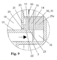
- WO 2010/045671 (Helmut Buchberger) describes an inhaler component for the intermittent, inhalation or train-synchronous formation of a vapor-air mixture or / and condensation aerosol, consisting of ( Fig. 9-12 and Figs. 17-18) a housing 3, a chamber 21 arranged in the housing 3, an air inlet opening 26 for the supply of air from the environment into the chamber 21, an electric heating element for the evaporation of a portion of a liquid material 16, the formed Steam in the chamber 21 mixes with the air supplied through the air inlet port 26 and forms the vapor-air mixture and / or condensation aerosol.
- the inhaler component further comprises a wick having a capillary structure, which wick forms a laminar structure 22 with the heating element and automatically re-energizes the heating element with the liquid material 16 after evaporation.
- the planar composite 22 is mounted with two end portions on two electrically conductive, plate-shaped contacts 23, on the surface of the heating element is electrically contacted simultaneously.
- the plate-shaped contacts may alternatively be formed by printed circuit boards or a common printed circuit board. At least one heated section of the planar composite 22 is arranged without contact in the chamber 21, and the capillary structure of the wick is largely free in the said section at least on one side 24 of the planar composite.
- the liquid container 4 has an openable closure 18, which is still closed before use.
- the openable closure 18 may be manually opened by a user, whereupon the liquid material 16 floods a reservoir 45 and wets the capillary gap 41.
- the capillary gap 41 draws the liquid material 16 from the liquid container 4 or reservoir 45 and transports it to the composite 22.
- the capillary gap 41 is basically formed by one of the two plate-shaped contacts 23 and a flat part 42 placed on top of these.
- a ventilation channel 52 is incorporated, which connects the reservoir 45 and the liquid container 4 with the chamber 21.
- the ventilation channel 52 causes a pressure equalization by each portion of liquid material 16, which passes into the capillary 41, is replaced immediately by a volume equal portion of air.
- the liquid container 4 is in the view after Fig. 9 above the composite 22 supporting, plate-shaped contacts 23 are arranged.
- This arrangement proves to be extremely cavity-demanding and causes the dimensions of the inhaler component to be relatively large.
- a further disadvantage is that the capillary gap 41 is very limited in its areal extent, insofar as in the vertical position of the capillary gap by the weight of acting in it liquid column in the reservoir 45, a negative pressure occurs, which must be compensated by the capillarity of the ventilation channel 52.
- the capillarity of the ventilation channel 52 is no longer sufficient to maintain equilibrium, the entire liquid material 16 in the liquid container 4 threatens to run out via the capillary gap 41.
- several composites are to be arranged next to each other (see Fig.
- the invention has for its object to overcome the above-mentioned disadvantages of the known from the prior art arrangement.
- the invention is in particular the object of an inhaler component of the type described in such a way that a comparatively compact overall arrangement can be achieved with a correspondingly small volume. Furthermore, capillary gaps with a larger areal extent should also be able to be provided.
- the capillary gap at least partially covers the liquid container in a view perpendicular to the carrier plate.
- the term "overlapping" also applies if further components are arranged between the capillary gap and the liquid container. Considering that the components forming the capillary gap require only little space perpendicular to the support plate, it is understood that space can be saved by the arrangement according to the invention.
- the composite at least partially covers the liquid container in a view perpendicular to the support plate.
- the term "overlapping" also applies if further components are arranged between the composite and the liquid container. If one observes that the composite is generally a relatively thin structure, it is clear that further space can be used to save space again.
- the carrier plate at least partially superimposed on the liquid container.
- the liquid container and the carrier plate are thus stacked one above the other. It is particularly advantageous in terms of construction if the liquid container has substantially the shape of a cuboid, and supports the carrier plate at least in sections on a side surface of the cuboid. As a result, the available space can be used in an optimal way.
- the carrier plate preferably consists of a printed circuit board, in particular of a multilayer so-called multilayer printed circuit board.
- the the electrical heating current to or dissipating interconnects can thus be divided into several layers, so that even very high heating currents can be transported largely lossless.
- the invention also relates to an inhaler comprising an inhaler component according to the invention as described above.
- the inhaler component can thus also be only a part, in particular a replaceable part of an inhaler.
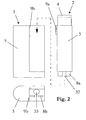
- Fig. 1 shows an inhaler according to the invention, the shape and size are designed so that the inhaler can be handled easily and conveniently by users. In volume, the inhaler is only about half the size of a pack of cigarettes.
- the inhaler exemplified consists basically of two parts, namely an inhaler part 1 and an inhaler component 2.
- the inhaler component 2 consists of a housing 3, which forms a tobacco pipe-like mouthpiece 4 on one end face.
- the housing 3 is preferably made of plastic.
- the inhaler component 2 contains a liquid material, which is electrically vaporized within the housing 3 and is converted into an inhalable vapor-air mixture and / or condensation aerosol.
- the formed vapor-air mixture and / or condensation aerosol is presented to the user via the mouthpiece 4.
- a liquid material are basically all substances and preparations into consideration, which evaporate largely free of residue under atmospheric conditions. This condition is fulfilled even if the respective substance or the respective preparation is diluted, for example, dissolved in water and / or ethanol, and the solution evaporates largely without residue.
- the aerosol particles produced by condensation generally have a mass median aerodynamic diameter (MMAD) of less than 2 ⁇ m and thereby also reach the alveoli.
- MMAD mass median aerodynamic diameter
- the inhaler according to the invention is particularly suitable for the administration of systemically active substances - in particular those active substances which display their main action in the central nervous system.
- nicotine is mentioned whose boiling point is 246 ° C.
- the nicotine-containing aerosol particles are precipitated predominantly in the bronchi and alveoli, where the active ingredient passes into the bloodstream in a flash. A few seconds later, the nicotine reaches Concentrated concentration of the brain and there can unfold the known effects.
- the inhaler part 1 consists of a main housing 5, which is preferably made of plastic again.
- the main body 5 includes at least a battery 6 and an electric circuit 7 (in FIG Fig. 1 shown in dashed lines) with switch 7a.
- the battery 6 and the electrical circuit 7 provide the necessary for the evaporation of the liquid material electrical energy.
- the battery 6 preferably consists of a rechargeable accumulator, for example of the type CGR18650K from the manufacturer Panasonic, www.industrial.panasonic.com. This is a cylindrical 18650 size lithium ion cell with a storage capacity of 1650mAh and a current carrying capacity of up to 30A. Comparable cells are also produced by other manufacturers, including Sony, Samsung, LG Chem, in large quantities.
- the inhaler part 1 and the inhaler component 2 in the specific embodiment are designed to be detachable from each other.
- This arrangement makes the inhaler part 1 reusable, which is basically useful, considering that firstly the inhaler part 1 does not come into contact with the liquid material, ie it is not contaminated with the liquid material, and secondly it contains components which are more durable As the components of the inhaler component 2.
- the inhaler component 2 after the liquid material is used up, disposed of properly by the user as a whole, and replaced by a new inhaler component 2.
- the inhaler component 2 thus represents a replaceable disposable article. Proper disposal is particularly indicated when the liquid material contains drugs or poisons such as nicotine.
- the mechanical coupling between the replaceable inhaler component 2 and the reusable inhaler part 1 takes place via tabs 8a and guide tabs 9a formed by the housing 3, which engage in corresponding plug sockets 8b and guide grooves 9b formed by the main housing 5 of the reusable inhaler part 1.
- the tabs 8a and sockets 8b simultaneously serve to introduce the electrical energy into the replaceable inhaler component 2 for evaporation of the liquid material, as will be shown in more detail below.
- Fig. 3a and Fig. 3b show different views of the interchangeable inhaler component 2.
- the Fig. 4-9 provide further information about the internal structure of the inhaler component 2.
- the housing 3 of the inhaler component 2 has a substantially cuboid shape.
- the essential components for the formation of the vapor-air mixture or / and Kondensationsaerosols include in particular the composites 10, which cause the evaporation of the liquid material.
- six composites 10 are arranged side by side, and the composites have a planar shape.
- the laminar composites 10 each consist of a wick and an electric heating element, which are connected to one another in a planar manner or integrated into one another in a planar manner.
- the laminar composites 10 may be formed, for example, by a metal foil and metal fabric layers sintered thereon. Instead of the metal fabric and open-cell metal foams can be used.
- the open-pored capillary structure of the fabric layers sintered onto the metal foil or the metal foam forms the wick, and the electrical resistance of the metal forms the heating element.
- Suitable metallic resistance materials are, for example, stainless steels such as AISI 304 or AISI 316 as well as heating conductor alloys, in particular NiCr alloys.
- the production of such laminar composites 10 belongs to the prior art and is for example in the already cited WO 2010/045671 (Helmut Buchberger) revealed in detail.
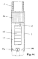
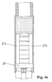
- Fig. 4b and Fig. 7 Best show the laminates 10 store with two end portions 10a, 10b on a support plate 11.
- the support plate 11 has a large recess 12, which is spanned by the bonds 10 without contact.
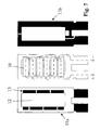
- the support plate 11 is designed in the concrete embodiment as a printed circuit board, in particular as a multilayer printed circuit board.
- As a material for the circuit board 11 are basically all known PCB materials, in particular the material types FR1 to FR5.
- the laminar composites 10 are electrically contacted in the region of the end sections 10a, 10b on printed conductors 13 of the printed circuit board 11. In Fig. 7 the tracks 13 are shown as black areas.
- the electrical contacting is preferably carried out by a foil-side soldering, optionally after pretreatment with a suitable flux.
- Stainless steels of the material qualities AISI 304 and AISI 316 can be soldered without problems, for example, using a soldering concentrate with the trade name "5050S-Nirosta" from Stannol GmbH, www.stannol.de.
- the electrical contacting may alternatively consist of an adhesive bond by means of an electrically conductive adhesive, for example by means of a silver-based epoxy-based adhesive.
- the assembly of the circuit board 11 with the laminar composites 10 and their contacting are fully automatic, with methods of the printed circuit board industry can be applied, which methods are otherwise suitable for mass production.
- the circuit board 11 projects out of the housing 3 in the form of the previously mentioned tabs 8a.
- the two tabs 8a serve to introduce the electrical energy into the inhaler component 2.
- the electrical energy is supplied to the composites 10 via the conductor tracks 13.
- the printed conductors 13 are arranged both on the front side 11a and on the rear side 11b of the printed circuit board 11, the front side 11a being the component side - this is the side on which the composites 10 are contacted.
- Further Conductor tracks can optionally also be arranged in intermediate layers.
- the individual interconnect layers are suitably connected to one another according to the prior art by means of so-called plated-through holes.
- Fig. 7 Furthermore, the current flow is shown. Accordingly, three composites 10 are connected in series in the concrete example in each case.
- the individual electrical resistances of the six composites 10 are of different sizes, for example by the thickness of the metal foil being varied accordingly. By this measure, the evaporation process similar to a cigarette can also be made dependent on the location.
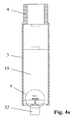
- a substantially plate-shaped, preferably made of plastic upper part 14 is placed (see Fig. 4c and Fig. 8-10 ).
- the upper part 14 has a recess 15, which correlates with respect to their size and arrangement with the recess 12 in the printed circuit board 11.
- the upper part 14 rests directly on the end sections 10a, 10b of the laminations 10.
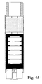
- the upper part 14 together with the printed circuit board 11 forms a capillary gap 16 whose inside width or gap width essentially corresponds to the thickness of the laminar laminates 10 (see FIG Fig. 9 and Fig. 10 ).
- the gap width is typically 0.2mm.
- Fig. 4d the areal extent of the capillary gap 16 is shown as a black area.
- the upper part 14 is fixed on the printed circuit board 11 by an adhesive connection, via two projections 14a, 14b and via a bracket 17.
- the printed circuit board 11 is mounted with its rear side 11b on a liquid container 19 containing the liquid material 18 (see FIG Fig. 4a / 4b . Fig. 8 and Fig. 10 ).
- the liquid container 19 or its wall is formed by the housing 3 and has a cuboid shape.
- the printed circuit board 11 is preferably fixed by means of an adhesive bond on the liquid container wall.
- the filling of the liquid container 19 with the liquid material 18 takes place at the factory at the end of the manufacturing process preferably via a small hole in the container wall (not shown) fully automatically by means of a cannula and a metering unit. The hole is closed after filling, for example sealed, and the whole inhaler component 2 is packaged airtight.
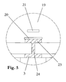
- the liquid container 19 has at its lower end two closely juxtaposed openings - the supply port 20 and the vent opening 21 (see Fig. 5 . Fig. 6 and Fig. 9 ).
- the supply opening 20 corresponds to a passage opening 22, which is formed by the edge of the circuit board 11 and an extension 23 of the liquid container wall (see Fig. 6 and Fig. 9 ).
- the extension 23 simultaneously forms a stop for the upper part 14.
- the extension 23 is supported via a web 24 on the housing 3.
- the supply of the capillary gap 16 with the liquid material 18 via the supply port 20 and the passage opening 22 and is driven by the capillary acting in the capillary 16 capillary forces.
- liquid material 18 In order for these capillary forces to act at all, it is necessary for the liquid material 18 to thoroughly wet all exposed surfaces. To ensure this, the affected components - these are the liquid container 19, the printed circuit board 11 together with composites 10 and the upper part 14 - to hydrophilize prior to assembly in a suitable process.
- Suitable processes are the hydrophilization in the oxygen plasma and the hydrophilization by means of plasma polymerization. Both processes, for example, by the company Diener electronic GmbH u. Co. KG, www.plasma.de, offered as part of contract work. The said company is also able to custom design and build appropriate, suitable for mass production facilities.
- the ventilation opening 21 corresponds to a ventilation groove 25 introduced into the printed circuit board 11, which in turn communicates via the recess 12 with an interior space which is at atmospheric pressure.
- the ventilation opening 21 and the ventilation groove 25 cause a pressure equalization, by replacing each portion of liquid material 18 which enters the capillary gap 16 with an equal volume of air.
- the sponges 27a, 27b receive condensate deposits formed in their pores from the vapor phase and prevent the inhalator component 2 from forming freely mobile condensate deposits which could impair the function of the inhaler component. Such condensate accumulations can also pose a problem from a hygienic point of view, in particular if they reach the oral cavity of a user via the mouthpiece 4.
- the sponges 27a, 27b preferably consist of a fine-pored fiber composite. Filtrona Fibertec GmbH, www.filtronafibertec.com, specializes in the production of such fiber composites using both triacetin-bound cellulose acetate fibers and thermally bonded polyolefin and polyester fibers.
- the sponges 27a, 27b bear on angle profiles 29a, 29b formed by a U-shaped support 29 (see FIG Fig. 4e and Fig. 10 ).
- the carrier 29 is joined to the upper part 14 by an adhesive connection.
- the carrier 29 together with angle sections 29a, 29b is preferably made of a hydrophobic plastic.
- the hydrophobic material acts as a liquid barrier and ensures that no liquid material 18 can reach the sponges 27a, 27b by capillary action.
- the angle sections 29a, 29b connecting leg 29c is on the upper part 14 side facing a recess 30 incorporated, which forms an air nozzle 31 together with the upper part 14 (see Fig. 9 and Fig. 10 ).
- the air nozzle 31 is, as will be shown in more detail later, the introduction of ambient air into the chamber 28. So that condensate deposits do not block the air nozzle 31, it is advisable to cover the Oberf kaue of the upper part 14 in the air nozzle 31 with a thin hydrophobic tape (not shown).
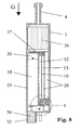
- the inhaler component 2 is supplied with ambient air to form the vapor / air mixture or / and condensation aerosol via a suction snorkel 32 formed by the housing 3 (see FIG Fig. 3a / 3b and Figure 8 ).
- the suction snorkel 32 is arranged on the side of the inhaler component 2 opposite the mouthpiece 4. This situation protects most from the Entry of rainwater.
- the suction snorkel 32 of the inhaler component 2 projects through a hole 33 formed through the main housing 5 of the inhaler part 1 (see FIG Fig. 2 ).
- In the intake snorkel 32 is a flow restrictor 34.
- the flow restrictor 34 has the purpose of creating a flow resistance which is similar to that of a cigarette, so that the user during a train feels a similar draw resistance as in a train on a cigarette. Specifically, the flow resistance should be at a flow rate of 1.05 L / min in the range 8-16 mbar and have a linear characteristic as possible.
- the flow restrictor 34 is required if the vapor-air mixture or / and condensation aerosol formed is to be supplied as in the case of a cigarette, namely as a pull into the oral cavity (tensile volume: approx. 20-80mL), optionally followed by inhalation into the lung , This mode of operation is recommended especially when the liquid material contains 18 nicotine.
- the flow restrictor 34 is eliminated if the inhaler is to permit direct pulmonary inhalation in a single step, as is the case with most medical inhalers.
- the flow restrictor 34 preferably consists of a cigarette filter-like fiber composite, wherein the density of the material is to be matched to the aforementioned flow characteristics.
- the material can in turn be obtained from Filtrona Fibertec GmbH, www.filtronafibertec.com.
- a user couples a new inhaler component 2 with the reusable inhaler part 1.
- the electrical circuit 7 registers the coupling and, if necessary, initiates certain preparatory operations, for example one or more evaporation cycles with the aim of to provide the composites 10 with fresh liquid material 18 and / or to produce stationary conditions. Once these operations are completed, the electrical circuit 7 signals, for example via a light emitting diode, the operational readiness of the inhaler.
- the user applies the mouthpiece 4 of the inhaler to the mouth and operates the switch 7a. At the same time he begins to pull the mouthpiece 4.
- the result generated negative pressure causes air from the environment flows into the intake snorkel 32.
- the flow bends at right angles (see arrows in Fig. 8 and Fig. 9 ) and opens into a plenum chamber 35, where the air collects and then evenly the slot-shaped air nozzle 31 is supplied.
- the air flow is accelerated in the air nozzle 31 and enters the chamber 28 at a high muzzle velocity.
- Actuation of the switch 7a causes the circuit 7 to turn on the heating current.
- the heating current is preferably switched by means of power MOSFET, wherein the supplied power can be adapted by a clocking (duty cycle) to the respective requirements. Within certain limits, this adaptation can also be carried out by the user via an interface, which makes it possible for him to influence the quantity of aerosol or smoke produced.
- the heating current is switched for a preset time period ("heating period"), which is typically 1.0-1.8 seconds.
- the heating current is supplied to the composites 10 via the tabs 8a and the printed conductors 13 of the printed circuit board 11 and causes a flash-like heating of the composites 10 and stored in the wicks liquid material 18, whereupon the liquid material 18 evaporates.
- the vapor is emitted into the chamber 28, where it mixes with the air flowing through the air nozzle 31.
- the arrangement and dimensioning of the air nozzle 31 causes a uniform and rapid flow over the composites 10. This ensures that the liberated from the composites 10 steam on all sides finds approximately the same mixing conditions, and the mixture of steam and air is intimately.
- the air causes cooling of the vapor, so that in addition a condensation aerosol can form, provided that the vaporized liquid material contains 18 substances with sufficiently low vapor pressure - so-called aerosol forming substances.
- a typical example of such aerosol forming substances is glycerol.
- the vapor-air mixture or / and condensation aerosol formed in the chamber 28 flows through one more time Cooler 36 before it is presented to the user via the mouthpiece 4 for inhalation (see Fig. 4e and Fig. 8 ).
- the cooler 36 may for example consist of a porous filling material, a non-woven fiber material or an open-cell foam material whose pores are flowed through by the formed vapor-air mixture or / and condensation aerosol.
- the cooler 36 may also be designed in several stages, with the individual cooler stages having different properties. If the material to be evaporated contains nicotine, it may be advantageous to coat the cooler material of at least one cooler stage with a suitable absorbent, for example with citric acid. The absorbent extracts from the flowing condensation aerosol highly volatile nicotine fractions, which would otherwise be deposited in the oral cavity and throat, which is neither pharmacokinetic nor organoleptically desirable. Flavoring agents such as menthol may also be added to the cooler material.
- Suitable non-woven fiber materials can be obtained, for example, from Freudenberg Nonwovens KG, www.freudenberg-filter.com.
- the material sold under the name Viledon® filter mats and consisting of polyolefin fibers is made to customer specification, wherein the material properties can be adjusted so that the end product for the fine particles of the condensation aerosol produced is largely permeable.
- a suitable foam material may be obtained, for example, from Dunlop Equipment, www.dunlop-equipment.com.
- the cited supplier offers Ni and NiCr foam under the product name Retimet® (Grade 80) with a porosity of 90-95% and a pore diameter of about 300 ⁇ m in sheet form up to thicknesses of 15mm.
- Ni foam and in particular NiCr foam are characterized by a high strength and by a high temperature and oxidation resistance. These characteristics suggest the comparatively expensive ones Metal foams at the end of the life of the Inhalatorkomponente 2 to recycle and reuse. If the liquid material contains 18 nicotine, the inhaler component 2 should in principle only be dispensed to the consumer against an adequate deposit. In this way it is ensured that the majority of contaminated with nicotine residues cooler 36, sponges 27a, 27b and liquid container 19 disposed of environmentally friendly and optionally recycled.
- the circuit 7 deactivates the switch 7a for a few seconds.
- the deactivation is indicated to the user by, for example, a light emitting diode and is required for the composites 10 to cool and for the wicks to re-soak with the liquid material 18.
- the liquid transport is originally induced by the capillarity of the composites 10 or their wicks.
- the wicks suck the liquid material 18 over the composite end portions 10a, 10b out of the capillary gap branches 16a, 16b (see FIG Fig. 4b and Fig. 10 ).
- the wicks are thus infiltrated from two sides.
- a nicotine-containing preparation of the liquid material 18 is disclosed, which was evaporated in prototypes (see Table 1).
- the condensation aerosol formed and administered in this case came with regard to the pharmacological, pharmacokinetic and organoleptic Effects very close to the smoke of a conventional cigarette. All listed ingredients are also found in cigarette smoke.
- the invention is of course not limited to one or more laminates 10 according to the embodiment just described.
- the composites 10 may also be formed linear or thread-like.
- the composites do not necessarily have to be even or straight, but rather can have any desired shape.
- the composites can also be electrically interconnected in any way.
- the invention also includes devices in which the liquid container 19 is arranged separable from the housing 3, so that the liquid container 19, as soon as it is empty, can be replaced by a new liquid container.
Landscapes
- Health & Medical Sciences (AREA)
- Engineering & Computer Science (AREA)
- General Health & Medical Sciences (AREA)
- Public Health (AREA)
- Anesthesiology (AREA)
- Biomedical Technology (AREA)
- Heart & Thoracic Surgery (AREA)
- Hematology (AREA)
- Life Sciences & Earth Sciences (AREA)
- Animal Behavior & Ethology (AREA)
- Veterinary Medicine (AREA)
- Pulmonology (AREA)
- Bioinformatics & Cheminformatics (AREA)
- Emergency Medicine (AREA)
- Containers And Packaging Bodies Having A Special Means To Remove Contents (AREA)
- Medicinal Preparation (AREA)
- Special Spraying Apparatus (AREA)
- Catching Or Destruction (AREA)
- Medical Preparation Storing Or Oral Administration Devices (AREA)
- Packages (AREA)
Description
- Die Erfindung betrifft eine Inhalatorkomponente für die Bildung eines Dampf-Luft-Gemisches oder/und Kondensationsaerosols durch Verdampfung eines flüssigen Materials und gegebenenfalls Kondensation des gebildeten Dampfes, umfassend:
- ein elektrisches Heizelement zur Verdampfung einer Portion des flüssigen Materials;
- einen Docht mit einer Kapillarstruktur, welcher Docht mit dem Heizelement einen Verbund bildet und das Heizelement selbsttätig mit dem flüssigen Material versorgt;
- eine Trägerplatte, vorzugsweise Leiterplatte, welche den Verbund trägt und auf welcher das Heizelement elektrisch kontaktiert ist;
- einen zumindest zum Teil durch die Trägerplatte gebildeten Kapillarspalt zur selbsttätigen Versorgung des Verbundes mit dem flüssigen Material, indem ein Endabschnitt des Dochts in den Kapillarspalt ragt;
- einen das flüssige Material enthaltenden Flüssigkeitsbehälter, von welchem der Kapillarspalt das flüssige Material bezieht.
- In der gegenständlichen Patentanmeldung bezieht sich der Begriff "Inhalator" auf medizinische wie nicht-medizinische Inhalatoren. Der Begriff bezieht sich ferner auf Inhalatoren zur Verabreichung von Arzneimitteln und solchen Stoffen, welche nicht als Arzneimittel deklariert sind. Der Begriff bezieht sich außerdem auf Rauchartikel und Zigarettenersatz-Artikel, wie sie beispielsweise in der Europäische Patentklasse A24F47/00B enthalten sind, soweit diese dazu bestimmt sind, dem Benutzer ein Dampf-Luft-Gemisch oder/und Kondensationsaerosol darzureichen. Der Begriff "Inhalator" soll auch keine Einschränkungen dahingehend machen, wie das gebildete Dampf-Luft-Gemisch oder/und Kondensationsaerosol dem Benutzer bzw. dessen Körper zugeführt wird. Das Dampf-Luft-Gemisch oder/und Kondensationsaerosol kann in die Lunge inhaliert werden, oder aber auch nur der Mundhöhle zugeführt werden - ohne Inhalation in die Lunge.
- Als "Kapillarspalt" gelte ein jeder Spalt, welcher allein aufgrund der Kapillarwirkung seiner Begrenzungswände einen Flüssigkeitstransport bewirkt. Dochte, ummantelte Dochte oder mit Dochtmaterial befüllte Kanäle sind keine Kapillarspalten.
- Die Verwendung des Singulars "Verbund" schließt das Vorhandensein mehrerer Verbunde nicht aus. Die Erfindung schließt Anordungen mit mehreren Verbunden explizit ein.
-
WO 2010/045671 (Helmut Buchberger) beschreibt eine Inhalatorkomponente für die intermittierende, inhalations- oder zugsynchrone Bildung eines Dampf-Luft-Gemisches oder/und Kondensationsaerosols, bestehend aus (Fig. 9-12 und Fig. 17-18) einem Gehäuse 3, eine im Gehäuse 3 angeordnete Kammer 21, eine Lufteinlaßöffnung 26 für die Zufuhr von Luft aus der Umgebung in die Kammer 21, ein elektrisches Heizelement zur Verdampfung einer Portion eines flüssigen Materials 16, wobei der gebildete Dampf sich in der Kammer 21 mit der durch die Lufteinlaßöffnung 26 zugeführten Luft mischt, und sich das Dampf-Luft-Gemisch oder/und Kondensationsaerosol bildet. Die Inhalatorkomponente umfaßt ferner einen Docht mit einer Kapillarstruktur, welcher Docht mit dem Heizelement einen flächigen Verbund 22 bildet und das Heizelement nach einer Verdampfung von neuem selbsttätig mit dem flüssigen Material 16 versorgt. Der flächige Verbund 22 lagert mit zwei Endabschnitten auf zwei elektrisch leitenden, plattenförmigen Kontakten 23, auf deren Oberfläche das Heizelement gleichzeitig elektrisch kontaktiert ist. Die plattenförmigen Kontakte können alternativ auch durch Leiterplatten oder eine gemeinsame Leiterplatte gebildet werden. Zumindest ein beheizter Abschnitt des flächigen Verbundes 22 ist berührungsfrei in der Kammer 21 angeordnet, und die Kapillarstruktur des Dochts liegt im besagten Abschnitt wenigstens auf einer Seite 24 des flächigen Verbundes weitgehend frei. Der flächige Verbund 22 bzw. dessen Docht ragt mit einem Ende in einen Kapillarspalt 41, welcher seinerseits mit einem das flüssige Material 16 enthaltenden Flüssigkeitsbehälter 4 kapillar gekoppelt bzw. koppelbar ist. Der Flüssigkeitsbehälter 4 weist einen offenbaren Verschluß 18 auf, welcher vor Gebrauch noch verschlossen ist. Der öffenbare Verschluß 18 kann von einem Benutzer manuell geöffnet werden, worauf das flüssige Material 16 ein Reservoir 45 flutet und den Kapillarspalt 41 benetzt. Der Kapillarspalt 41 zieht das flüssige Material 16 aus dem Flüssigkeitsbehälter 4 bzw. Reservoir 45 und transportiert es zum Verbund 22. Der Kapillarspalt 41 wird im Grunde durch einen der beiden plattenförmigen Kontakte 23 und ein auf diesen flächig aufgesetztes Oberteil 42 gebildet. Des Weiteren ist in den plattenförmigen Kontakt 23 ein Belüftungskanal 52 eingearbeitet, welcher das Reservoir 45 bzw. den Flüssigkeitsbehälter 4 mit der Kammer 21 verbindet. Der Belüftungskanal 52 bewirkt einen Druckausgleich, indem jede Portion flüssigen Materials 16, welche in den Kapillarspalt 41 gelangt, unmittelbar durch eine volumengleiche Portion Luft ersetzt wird. - Der Flüssigkeitsbehälter 4 ist in der Ansicht nach
Fig. 9 oberhalb der den Verbund 22 tragenden, plattenförmigen Kontakte 23 angeordnet. Diese Anordung erweist sich als ausgesprochen raümfordernd und führt dazu, daß die Abmessungen der Inhalatorkomponente relativ groß ausfallen. Ein weiterer Nachteil ist, daß der Kapillarspalt 41 in seiner flächigen Ausdehnung sehr limitiert ist, insofern als bei senkrechter Lage des Kapillarspalts durch das Gewicht der in ihm wirkenden Flüssigkeitssäule im Reservoir 45 ein Unterdruck auftritt, welcher durch die Kapillarität des Belüftungskanals 52 kompensiert werden muß. Reicht die Kapillarität des Belüftungskanals 52 jedoch nicht mehr aus, das Gleichgewicht zu halten, droht das gesamte flüssige Material 16 im Flüssigkeitsbehälter 4 über den Kapillarspalt 41 auszulaufen. Vor allem wenn mehrere Verbunde nebeneinander angeordnet werden sollen (vgl. Fig. 29), oder/und der Docht über zwei voneinander entfernt angeordneten Endabschnitten infiltriert werden soll, ist eine entsprechend große flächige Ausdehnung des Kapillarspalts 41 erforderlich, welche mit der zuvor beschriebenen Anordnung nachWO 2010/045671 aufgrund der aufgezeigten Wirkungen kaum realisierbar ist. - Der Erfindung liegt die Aufgabe zugrunde, die zuvor aufgezeigten Nachteile der aus dem Stand der Technik bekannten Anordnung zu beheben. Der Erfindung liegt insbesondere die Aufgabe zugrunde, eine Inhalatorkomponente der eingangs geschilderten Art so auszugestalten, daß eine vergleichsweise kompakte Gesamtanordnung mit einem entsprechend kleinen Bauvolumen erzielt werden kann. Ferner sollen auch Kapillarspalten mit einer größeren flächigen Ausdehnung vorgesehen werden können.
- Die Aufgabe wird durch die kennzeichnenden Merkmale des Patentanspruches 1 gelöst. Demnach ist vorgesehen, daß der Kapillarspalt den Flüssigkeitsbehälter in einer Ansicht senkrecht zur Trägerplatte außen zumindest teilweise überdeckt. Im Sinne der vorliegenden Erfindung gelte auch als "überdeckend", wenn zwischen dem Kapillarspalt und dem Flüssigkeitsbehälter noch weitere Bauteile angeordnet sind. Bedenkt man, daß die den Kapillarspalt bildenden Komponenten senkrecht zur Trägerplatte nur wenig Raum fordern, wird verständlich, daß durch die erfindungsgemäße Anordung Bauraum eingespart werden kann.
- In einer Weiterbildung der Erfindung ist vorgesehen, daß der Verbund den Flüssigkeitsbehälter in einer Ansicht senkrecht zur Trägerplatte zumindest teilweise überdeckt. Im Sinne der vorliegenden Erfindung gelte auch als "überdeckend", wenn zwischen dem Verbund und dem Flüssigkeitsbehälter noch weitere Bauteile angeordnet sind. Beachtet man, daß es sich beim Verbund in der Regel um ein relativ dünnes Gebilde handelt, leuchtet ein, daß durch diese weitere Überdeckung nochmals Bauraum eingespart werden kann.
- In einer bevorzugten Ausbildung der Erfindung ist vorgesehen, daß die Trägerplatte zumindest abschnittsweise auf dem Flüssigkeitsbehälter lagert. Der Flüssigkeitsbehälter und die Trägerplatte sind also übereinander gestapelt angeordnet. Konstruktiv besonders vorteilhaft ist es, wenn der Flüssigkeitsbehälter im Wesentlichen die Form eines Quaders hat, und die Trägerplatte zumindest abschnittsweise auf einer Seitenfläche des Quaders lagert. Hierdurch kann der zur Verfügung stehende Bauraum in optimaler Weise genutzt werden. Die Trägerplatte besteht vorzugsweise aus einer Leiterplatte, insbesondere aus einer mehrlagigen sogenannten Multilayer-Leiterplatte. Die den elektrischen Heizstrom zu- bzw. abführenden Leiterbahnen können dadurch nämlich auf mehrere Lagen aufgeteilt werden, so daß auch sehr hohe Heizströme weitgehend verlustfrei transportiert werden können.
- Die Erfindung betrifft außerdem einen Inhalator, umfassend eine erfindungsgemäße Inhalatorkomponente wie zuvor beschrieben. Die Inhalatorkomponente kann also auch nur ein Teil, insbesondere ein auswechselbares Teil eines Inhalators sein.
- Die Erfindung wird anhand eines Ausführungsbeispiels gemäß den Zeichnungen näher erläutert.
- Es zeigen:
-
Fig. 1 einen erfindungsgemäßen Inhalator in verschiedenen Ansichten; -
Fig. 2 den Inhalator nachFig. 1 mit einem wiederverwendbaren Inhalatorteil und einer auswechselbaren Inhalatorkomponente im entkoppelten Zustand; -
Fig. 3a undFig 3b die auswechselbare Inhalatorkomponente in verschiedenen Ansichten; -
Fig. 4a ,Fig. 4b ,Fig. 4c ,Fig. 4d undFig. 4e Schnittansichten der auswechselbaren Inhalatorkomponente längs der Linie A-A inFig. 3b in verschiedenen Montagezuständen; -
Fig. 5 das Detail a ausFig. 4a in einer vergrößerten Darstellung; -
Fig. 6 das Detail b ausFig. 4b in einer vergrößerten Darstellung; -
Fig. 7 eine als Multilayer-Leiterplatte ausgeführte Trägerplatte; -
Fig. 8 eine Schnittansicht der auswechselbaren Inhalatorkomponente längs der Linie B-B inFig. 3b ; -
Fig. 9 das Detail c ausFig. 8 in einer vergrößerten Darstellung; -
Fig. 10 eine Schnittansicht der auswechselbaren Inhalatorkomponente in Höhe der Verbunde längs der Linie C-C inFig. 3b . -
Fig. 1 zeigt einen erfindungsgemäßen Inhalator, dessen Form und Größe derart gestaltet sind, daß der Inhalator von Benutzern einfach und bequem gehandhabt werden kann. Volumenmäßig ist der Inhalator nur etwa halb so groß wie eine Zigarettenschachtel. Der beispielhaft dargestellte Inhalator besteht grundsätzlich aus zwei Teilen, nämlich aus einem Inhalatorteil 1 und einer Inhalatorkomponente 2. - Die Inhalatorkomponente 2 besteht aus einem Gehäuse 3, welches an einer Stirnseite ein tabakpfeifenartiges Mundstück 4 ausbildet. Das Gehäuse 3 ist vorzugsweise aus Kunststoff gefertigt. Die Inhalatorkomponente 2 beinhaltet ein flüssiges Material, welches innerhalb des Gehäuses 3 elektrisch verdampft wird und in ein inhalierbares Dampf-Luft-Gemisch oder/und Kondensationsaerosol übergeführt wird. Das gebildete Dampf-Luft-Gemisch oder/und Kondensationsaerosol wird dem Benutzer über das Mundstück 4 dargeboten. Als flüssiges Material kommen grundsätzlich alle Stoffe und Zubereitungen in Betracht, welche unter atmosphärischen Bedingungen weitgehend rückstandsfrei verdampfen. Diese Bedingung ist auch schon erfüllt, wenn der jeweilige Stoff oder die jeweilige Zubereitung verdünnt, beispielsweise in Wasser oder/ und Ethanol gelöst vorliegt und die Lösung weitgehend rückstandsfrei verdampft. Durch eine hinreichend hohe Verdünnung in einem leicht flüchtigen Lösungsmittel wie Wasser oder/und Ethanol können auch sonst schwer verdampfbare Stoffe die zuvor genannte Bedingung erfüllen, und eine thermische Zersetzung des flüssigen Materials vermieden oder deutlich verringert werden. Die durch Kondensation erzeugten Aerosolteilchen weisen in der Regel einen massemedianen aerodynamischen Durchmesser (MMAD) kleiner als 2µm auf und erreichen dadurch auch die Alveolen. Der erfindungsgemäße Inhalator eignet sich insbesondere für die Verabreichung von systemisch wirkenden Stoffen - insbesondere solchen Wirkstoffen, welche ihre Hauptwirkung im zentralen Nervensystem entfalten. Als Beispiel sei Nikotin erwähnt, dessen Siedepunkt bei 246°C liegt. Die nikotinhaltigen Aerosolpartikel werden vorwiegend in den Bronchien und Alveolen niedergeschlagen, wo der Wirkstoff blitzartig in den Blutkreislauf übergeht. Wenige Sekunden später erreicht das Nikotin in gebündelter Konzentration das Gehirn und kann dort die bekannten Wirkungen entfalten.
- Das Inhalatorteil 1 besteht aus einem Hauptgehäuse 5, welches vorzugsweise wieder aus Kunststoff gefertigt ist. Das Hauptgehäuse 5 beinhaltet zumindest eine Batterie 6 und einen elektrischen Schaltkreis 7 (in
Fig. 1 strichliert dargestellt) samt Schalter 7a. Die Batterie 6 und der elektrische Schaltkreis 7 stellen die für die Verdampfung des flüssigen Materials erforderliche elektrische Energie bereit. Die Batterie 6 besteht vorzugsweise aus einem wiederaufladbaren Akkumulator, beispielsweise vom Typ CGR18650K des Herstellers Panasonic, www.industrial.panasonic.com. Hierbei handelt es sich um eine zylindrische Lithium-Ionen-Zelle der Baugröße 18650 mit einer Speicherkapazität von 1650mAh und einer Strom-Belastbarkeit von bis zu 30A. Vergleichbare Zellen werden auch von anderen Herstellern, u.a. Sony, Samsung, LG Chem, in großen Stückzahlen gefertigt. - Wie die
Fig. 2 zeigt, sind das Inhalatorteil 1 und die Inhalatorkomponente 2 im konkreten Ausführungsbeispiel voneinander lösbar ausgeführt. Diese Anordnung macht das Inhalatorteil 1 wiederverwendbar, was grundsätzlich sinnvoll ist, wenn man in Betracht zieht, daß erstens das Inhalatorteil 1 mit dem flüssigen Material nicht in Berührung kommt, also nicht mit dem flüssigen Material kontaminiert wird, und zweitens Komponenten beinhaltet, welche langlebiger sind als die Bestandteile der Inhalatorkomponente 2. Die Inhalatorkomponente 2 wird, nachdem das flüssige Material aufgebraucht ist, vom Benutzer als Ganzes sachgerecht entsorgt, und durch eine neue Inhalatorkomponente 2 ersetzt. Die Inhalatorkomponente 2 stellt insofern einen auswechselbaren Einwegartikel dar. Eine sachgerechte Entsorgung ist vor allem dann angezeigt, wenn das flüssige Material Arzneimittel oder Gifte wie Nikotin enthält. Grundsätzlich wäre es natürlich auch denkbar, das Inhalatorteil 1 und die Inhalatorkomponente 2 einteilig, also voneinander untrennbar auszuführen. Diese Ausführungsform dürfte jedoch unwirtschaftlicher sein, weil in diesem Fall alle Teile und Komponenten des Inhalators, also der Inhalator als Ganzes einen Einwegartikel zur einmaligen Benutzung bildet. Selbstverständlich schließt die gegenständliche Erfindung auch diese Ausführungsform mit ein, wobei in diesem Fall der ganze Inhalator als Inhalatorkomponente aufzufassen ist. - Die mechanische Kopplung zwischen der auswechselbaren Inhalatorkomponente 2 und dem wiederverwendbaren Inhalatorteil 1 erfolgt über Steckzungen 8a und durch das Gehäuse 3 gebildete Führungsnasen 9a, welche in korrespondierende, durch das Hauptgehäuse 5 des wiederverwendbaren Inhalatorteils 1 gebildete Steckbuchsen 8b und Führungsnuten 9b eingreifen. Die Steckzungen 8a und Steckbuchsen 8b dienen gleichzeitig zur Einleitung der elektrischen Energie in die auswechselbare Inhalatorkomponente 2 zur Verdampfung des flüssigen Materials, wie nachfolgend noch detaillierter gezeigt wird.
-
Fig. 3a undFig. 3b zeigen verschiedene Ansichten der auswechselbaren Inhalatorkomponente 2. DieFig. 4-9 geben weiteren Aufschluss über den inneren Aufbau der Inhalatorkomponente 2. Demnach weist das Gehäuse 3 der Inhalatorkomponente 2 im Wesentlichen eine quaderförmige Gestalt auf. Im Inneren des quaderförmigen Gehäuses 3 befinden sich die für die Bildung des Dampf-Luft-Gemisches oder/und Kondensationsaerosols wesentlichen Komponenten. Zu diesen zählen insbesondere die Verbunde 10, welche die Verdampfung des flüssigen Materials bewirken. Im konkreten Ausführungsbeispiel sind sechs Verbunde 10 nebeneinander angeordnet, und die Verbunde haben eine flächige Gestalt. Die flächigen Verbunde 10 bestehen jeweils aus einem Docht und einem elektrischen Heizelement, welche miteinander flächig verbunden oder flächig ineinander integriert sind. Die flächigen Verbunde 10 können beispielsweise durch eine Metallfolie und darauf aufgesinterte Metallgewebelagen gebildet werden. Statt des Metallgewebes können auch offenporige Metallschäume Verwendung finden. Die offenporige Kapillarstruktur der auf die Metallfolie aufgesinterten Gewebelagen bzw. des Metallschaums bildet den Docht, und der elektrische Widerstand des Metalls bildet das Heizelement. Geeignete metallische Widerstandsmaterialien sind beispielsweise Edelstähle wie AISI 304 oder AISI 316 sowie Heizleiterlegierungen, insbesondere NiCr-Legierungen. Die Herstellung solcher flächigen Verbunde 10 zählt zum Stand der Technik und wird beispielsweise in der bereits zitiertenWO 2010/045671 (Helmut Buchberger) im Detail offenbart. - Wie
Fig. 4b undFig. 7 am besten zeigen, lagern die flächigen Verbunde 10 mit zwei Endabschnitten 10a, 10b auf einer Trägerplatte 11. Die Trägerplatte 11 weist eine große Ausnehmung 12 auf, welche von den Verbunden 10 berührungsfrei überspannt wird. Die Trägerplatte 11 ist im konkreten Ausführungsbeispiel als Leiterplatte, insbesondere als Multilayer-Leiterplatte ausgeführt. Als Material für die Leiterplatte 11 eignen sich grundsätzlich alle bekannten Leiterplatten-Werkstoffe, insbesondere die Werkstofftypen FR1 bis FR5. Die flächigen Verbunde 10 sind im Bereich der Endabschnitte 10a, 10b auf Leiterbahnen 13 der Leiterplatte 11 elektrisch kontaktiert. InFig. 7 sind die Leiterbahnen 13 als schwarze Flächen dargestellt. Im Fall der zuvor beschriebenen Metallfolien-Verbunde erfolgt die elektrische Kontaktierung vorzugsweise durch eine folienseitige Lötung, gegebenenfalls nach Vorbehandlung mit einem geeigneten Flussmittel. Edelstähle der Werkstoff-Qualitäten AISI 304 und AISI 316 können beispielsweise mit einem Lötkonzentrat mit der Handelbezeichnung "5050S-Nirosta" der Firma Stannol GmbH, www.stannol.de, problemlos gelötet werden. Die elektrische Kontaktierung kann alternativ aus einer Klebeverbindung mittels eines elektrisch leitenden Klebstoffes, zum Beispiel mittels eines silberhaltigen Klebers auf Epoxidbasis, bestehen. Die Bestückung der Leiterplatte 11 mit den flächigen Verbunden 10 sowie deren Kontaktierung erfolgen vollautomatisch, wobei Verfahren der Leiterplattenindustrie angewandt werden können, welche Verfahren sich im Übrigen auch für eine Massenfertigung eignen. - Die Leiterplatte 11 ragt aus dem Gehäuse 3 in Form der bereits früher erwähnten Steckzungen 8a heraus. Die beiden Steckzungen 8a dienen zur Einleitung der elektrischen Energie in die Inhalatorkomponente 2. Die elektrische Energie wird den Verbunden 10 über die Leiterbahnen 13 zugeführt. Nach
Fig. 7 sind die Leiterbahnen 13 sowohl auf der Vorderseite 11a als auch auf der Rückseite 11b der Leiterplatte 11 angeordnet, wobei die Vorderseite 11a die Bestückungsseite ist - das ist jene Seite, auf welcher die Verbunde 10 kontaktiert sind. Weitere Leiterbahnen können optional auch noch in Zwischenlagen angeordnet werden. Die einzelnen Leiterbahn-Lagen sind nach dem Stand der Technik mittels sogenannter Durchkontaktierungen zweckmäßig miteinander verbunden. InFig. 7 ist ferner der Stromfluß dargestellt. Demnach sind im konkreten Beispiel jeweils drei Verbunde 10 miteinander in Reihe geschaltet. Dadurch kann auf den resultierenden Heizwiderstand und damit auf die Heizleistung und Verdampfungrate in gewissen Grenzen Einfluß genommen werden. Es kann auch vorgesehen sein, daß die elektrischen Einzelwiderstände der sechs Verbunde 10 unterschiedlich groß sind, indem beispielsweise die Dicke der Metallfolie entsprechend variiert wird. Durch diese Maßnahme kann der Verdampfungsprozeß ähnlich wie in einer Zigarette auch vom Ort abhängig gemacht werden. - Auf die Vorderseite 11a der Leiterplatte 11 ist ein im Wesentlichen plattenförmiges, vorzugsweise aus Kunststoff bestehendes Oberteil 14 aufgesetzt (siehe
Fig. 4c undFig. 8-10 ). Das Oberteil 14 weist eine Aussparung 15 auf, welche hinsichtlich ihrer Größe und Anordnung mit der Ausnehmung 12 in der Leiterplatte 11 korreliert. Im einfachsten Fall lagert das Oberteil 14 direkt auf den Endabschnitten 10a, 10b der flächigen Verbunde 10. Hierdurch bildet das Oberteil 14 zusammen mit der Leiterplatte 11 einen Kapillarspalt 16, dessen lichte Weite bzw. Spaltbreite im Wesentlichen der Dicke der flächigen Verbunde 10 entspricht (sieheFig. 9 undFig. 10 ). Die Spaltbreite beträgt typischerweise 0,2mm. InFig. 4d ist die flächige Ausdehnung des Kapillarspalts 16 als schwarze Fläche dargestellt. Das Oberteil 14 ist auf der Leiterplatte 11 durch eine Klebeverbindung befestigt, und zwar über zwei Vorsprünge 14a, 14b und über einen Haltewinkel 17. - Die Leiterplatte 11 lagert mit ihrer Rückseite 11b auf einem das flüssige Material 18 enthaltenden Flüssigkeitsbehälter 19 (siehe
Fig. 4a /4b ,Fig. 8 undFig. 10 ). Der Flüssigkeitsbehälter 19 bzw. dessen Wand wird durch das Gehäuse 3 gebildet und weist eine quaderförmige Gestalt auf. Die Leiterplatte 11 ist vorzugsweise mittels einer Klebeverbindung auf der Flüssigkeitsbehälterwand befestigt. Die Befüllung des Flüssigkeitsbehälters 19 mit dem flüssigen Material 18 erfolgt werkseitig am Ende des Fertigungsprozesses vorzugsweise über ein kleines Loch in der Behälterwand (nicht dargestellt) vollautomatisch mittels einer Kanüle und einer Dosiereinheit. Das Loch wird nach der Befüllung verschlossen, zum Beispiel zugeschmolzen, und die ganze Inhalatorkomponente 2 luftdicht verpackt. - Der Flüssigkeitsbehälter 19 weist an seinem unteren Ende zwei eng nebeneinander angeordnete Öffnungen auf - die Versorgungsöffnung 20 und die Belüftungsöffnung 21 (siehe
Fig. 5 ,Fig. 6 undFig. 9 ). Die Versorgungsöffnung 20 korrespondiert mit einer Durchtrittsöffnung 22, welche durch den Rand der Leiterplatte 11 und einen Fortsatz 23 der Flüssigkeitsbehälterwand gebildet wird (sieheFig. 6 undFig. 9 ). Der Fortsatz 23 bildet gleichzeitig einen Anschlag für das Oberteil 14. Zur Aussteifung stützt sich der Fortsatz 23 über einen Steg 24 am Gehäuse 3 ab. Die Versorgung des Kapillarspalts 16 mit dem flüssigen Material 18 erfolgt über die Versorgungsöffnung 20 und die Durchtrittsöffnung 22 und wird durch die im Kapillarspalt 16 wirkenden Kapillarkräfte angetrieben. Damit diese Kapillarkräfte überhaupt wirken können, ist es erforderlich, daß das flüssige Material 18 sämtliche beaufschlagten Oberflächen gut benetzt. Um dies sicherzustellen, sind die betroffenen Bauteile - das sind der Flüssigkeitsbehälter 19, die Leiterplatte 11 samt Verbunden 10 und das Oberteil 14 - noch vor der Montage in einem geeigneten Prozeß zu hydrophilieren. Geeignete Prozesse sind das Hydrophilieren im Sauerstoff-Plasma sowie das Hydrophilieren mittels Plasmapolymerisation. Beide Prozesse werden beispielsweise von der Firma Diener electronic GmbH u. Co. KG, www.plasma.de, im Rahmen von Lohnaufträgen angeboten. Die genannte Firma ist außerdem in der Lage, entsprechende, auch für eine Massenfertigung taugliche Anlagen kundenspezifisch zu planen und zu errichten. - Die Belüftungsöffnung 21 korrespondiert mit einer in die Leiterplatte 11 eingebrachten Belüftungsnut 25, welche ihrerseits über die Ausnehmung 12 mit einem unter Atmosphärendruck stehenden Innenraum kommuniziert. Die Belüftungsöffnung 21 und die Belüftungsnut 25 bewirken einen Druckausgleich, indem jede Portion flüssigen Materials 18, welche in den Kapillarspalt 16 gelangt, unmittelbar durch eine volumengleiche Portion Luft ersetzt wird.
- Die überlappende Anordnung der Leiterplatte 11 und des Flüssigkeitsbehälters 19, sowie die zuvor beschriebene Anordnung der Versorgungsöffnung 20, der Durchtrittsöffnung 22 und der Belüftungsöffnung 21 gestatten es, eine vergleichsweise große Kapillarspaltfläche vorzusehen, welche erforderlich ist, wenn mehrere nebeneinander angeordnete Verbunde 10 mit dem flüssigen Material 18 zu versorgen sind. Die Gefahr, daß an irgendeiner Stelle durch das Wirken der Gravitation flüssiges Material 18 austritt, kann weitestgehend abgewendet werden. In der in
Fig. 8 dargestellten senkrechten Lage der Inhalatorkomponente 2 (ein Pfeil zeigt die Wirkrichtung der Gravitation an) herrscht in der Belüftungsöffnung 21 ännähernd Atmosphärendruck, da sich der Kapillarspalt 16 in Bezug auf die Durchtrittsöffnung 22 nach unten hin nicht weiter ausdehnt (vgl.Fig. 4d ). In einer auf den Kopf gestellten Lage der Inhalatorkomponente 2 (das Mundstück 4 weist nach unten) kann die Flüssigkeitssäule im Kapillarspalt 16 zwar einen Unterdruck induzieren, dieser kann jedoch auf das flüssige Material 18 im Flüssigkeitsbehälter 19 nicht zurückwirken, weil ein Luftpolster im Flüssigkeitsbehälter 19 die kapillare Kopplung unterbricht. Bei der werkseitigen Befüllung des Flüssigkeitsbehälters 19 ist lediglich darauf zu achten, daß ein kleines Luftvolumen 26 zur Bildung des Luftpolsters im Behälter verbleibt. - Bevor auf die Funktionsweise des erfindungsgemäßen Inhalators näher eingegangen wird, sollen im Folgenden noch weitere Bestandteile der Inhalatorkomponente 2 beschrieben werden. Auch wenn diese Bestandteile nicht unmittelbar erfindungsrelevant sein mögen, so trägt die Beschreibung derselben doch dazu bei, die Funktion der erfindungsgemäßen Inhalatorkomponente im Ganzen noch besser zu verstehen, und die Ausführbarkeit der Erfindung noch sicherer zu gewährleisten: zwischen dem Oberteil 14 und dem Gehäuse 3 sind zwei offenporige, saugfähige Schwämme 27a, 27b (siehe
Fig. 4e undFig. 10 ) angeordnet. Der Raum zwischen den Schwämmen bildet zusammen mit der Aussparung 15 eine Kammer 28 (vgl. auchFig. 8 ), in welcher die eigentliche Bildung des Dampf-Luft-Gemisches oder/und Kondensationsaerosols stattfindet. Die Schwämme 27a, 27b nehmen in ihren Poren aus der Dampfphase gebildete Kondensatablagerungen auf und verhindern, daß sich in der Inhalatorkomponente 2 frei bewegliche Kondensatansammlungen bilden, welche die Funktion der Inhalatorkomponente beeinträchtigen könnten. Solche Kondensatansammlungen können auch aus hygienischer Sicht ein Problem darstellen, insbesondere wenn sie über das Mundstück 4 in die Mundhöhle eines Benutzers gelangen. Die Schwämme 27a, 27b bestehen vorzugsweise aus einem feinporigen Faserverbund. Die Firma Filtrona Fibertec GmbH, www.filtronafibertec.com, ist auf die Herstellung solcher Faserverbunde spezialisiert, wobei sowohl mittels Triacetin gebundene Celluloseacetat-Fasern als auch thermisch gebundene Polyolefin- und Polyesterfasern verarbeitet weden. - Die Schwämme 27a, 27b lagern auf von einem U-förmigen Träger 29 gebildeten Winkelprofilen 29a, 29b (siehe
Fig. 4e undFig. 10 ). Der Träger 29 ist mit dem Oberteil 14 durch eine Klebeverbindung gefügt. Der Träger 29 samt Winkelprofilen 29a, 29b besteht vorzugsweise aus einem hydrophoben Kunststoff. Das hydrophobe Material wirkt wie eine Flüssigkeitssperre und stellt sicher, daß kein flüssiges Material 18 durch Kapillareffekte zu den Schwämmen 27a, 27b gelangen kann. In den die Winkelprofile 29a, 29b verbindenden Schenkel 29c ist auf der dem Oberteil 14 zugewandten Seite eine Vertiefung 30 eingearbeitet, welche zusammen mit dem Oberteil 14 eine Luftdüse 31 bildet (sieheFig. 9 undFig. 10 ). Die Luftdüse 31 dient, wie später noch näher dargestellt wird, der Einbringung von Umgebungsluft in die Kammer 28. Damit Kondensatablagerungen die Luftdüse 31 nicht blockieren, empfiehlt es sich, die Oberfäche des Oberteils 14 im Bereich der Luftdüse 31 mit einem dünnen hydrophoben Klebeband zu überkleben (nicht dargestellt). - Die Versorgung der Inhalatorkomponente 2 mit Umgebungsluft zur Bildung des Dampf-Luft-Gemisches oder/und Kondensationsaerosols erfolgt über einen durch das Gehäuse 3 gebildeten Ansaugschnorchel 32 (siehe
Fig. 3a /3b undFig.8 ). Der Ansaugschnorchel 32 ist auf der dem Mundstück 4 gegenüberliegenden Seite der Inhalatorkomponente 2 angeordnet. Diese Lage schützt am ehesten vor dem Eintritt von Regenwasser. Im gekoppelten Zustand ragt der Ansaugschnorchel 32 der Inhalatorkomponente 2 durch ein durch das Hauptgehäuse 5 des Inhalatorteils 1 gebildetes Loch 33 (sieheFig. 2 ). Im Ansaugschnorchel 32 befindet sich eine Strömungsdrossel 34. Die Strömungsdrossel 34 hat den Zweck, einen Strömungswiderstand zu erzeugen, welcher dem einer Zigarette ähnlich ist, so daß der Benutzer während eines Zuges einen ähnlichen Zugwiderstand verspürt wie bei einem Zug an einer Zigarette. Konkret sollte der Strömungswiderstand bei einem Durchfluß von 1,05 L/min im Bereich 8-16mbar liegen und eine möglichst lineare Charakteristik aufweisen. Die Strömungsdrossel 34 ist erforderlich, wenn das gebildete Dampf-Luft-Gemisch oder/und Kondensationsaerosol wie bei einer Zigarette zugeführt werden soll, nämlich als Zug in die Mundhöhle (Zugvolumen: ca. 20-80mL), gegebenenfalls gefolgt von einer Inhalation in die Lunge. Diese Betriebsweise empfiehlt sich vor allem dann, wenn das flüssige Material 18 Nikotin enthält. Die Strömungsdrossel 34 entfällt jedoch, wenn der Inhalator eine direkte Lungeninhalation in einem einzigen Schritt gestatten soll, wie dies bei den meisten medizinischen Inhalatoren der Fall ist. Die Strömungsdrossel 34 besteht vorzugsweise aus einem zigarettenfilterähnlichen Faserverbund, wobei die Dichte des Materials auf die zuvor genannte Durchflußcharakteristik abzustimmen ist. Das Material kann wiederum von der Firma Filtrona Fibertec GmbH, www.filtronafibertec.com, bezogen werden. - Im Folgenden soll die Funktion des Inhalators im Detail beschrieben werden: ein Benutzer koppelt eine neue Inhalatorkomponente 2 mit dem wiederverwendbaren Inhalatorteil 1. Der elektrische Schaltkreis 7 registriert die Kopplung und veranlaßt gegebenenfalls die Ausführung bestimmter vorbereitender Operationen, beispielsweise eines oder mehrerer Verdampfungszyklen mit dem Ziel, die Verbunde 10 mit frischem flüssigen Material 18 zu versorgen oder/und stationäre Bedingungen herzustellen. Sobald diese Operationen abgeschlossen sind, signalisiert der elektrische Schaltkreis 7 zum Beispiel über eine Leuchtdiode die Betriebsbereitschaft des Inhalators. Der Benutzer führt das Mundstück 4 des Inhalators an den Mund und betätigt den Schalter 7a. Gleichzeitig beginnt er am Mundstück 4 zu ziehen. Der hierdurch erzeugte Unterdruck bewirkt, daß Luft aus der Umgebung in den Ansaugschnorchel 32 strömt. Nachdem die Luft die Strömungsdrossel 34 durchsetzt hat, biegt die Strömung im rechten Winkel ab (siehe Pfeile in
Fig. 8 undFig. 9 ) und mündet in eine Plenumkammer 35, wo sich die Luft sammelt und sodann gleichmäßig der schlitzförmigen Luftdüse 31 zugeführt wird. Die Luftströmung wird in der Luftdüse 31 beschleunigt und tritt mit einer hohen Mündungsgeschwindigkeit in die Kammer 28 ein. - Die Betätigung des Schalters 7a bewirkt, daß der Schaltkreis 7 den Heizstrom einschaltet. Der Heizstrom wird vorzugsweise mittels Leistungs-MOSFET geschaltet, wobei die zugeführte Leistung durch eine Taktung (Duty Cycle) den jeweiligen Erfordernissen angepaßt werden kann. Diese Anpassung kann in bestimmten Grenzen auch durch den Benutzer über eine Schnittstelle erfolgen, wodurch es diesem ermöglicht wird, auf die erzeugte Aerosol- bzw. Rauchmenge Einfluß zu nehmen. Der Heizstrom wird für eine voreingestellte Zeitperiode ("Heizperiode") geschaltet, welche typischerweise 1,0-1,8 Sekunden beträgt. Der Heizstrom wird den Verbunden 10 über die Steckzungen 8a und die Leiterbahnen 13 der Leiterplatte 11 zugeführt und bewirkt eine blitzartige Aufheizung der Verbunde 10 und des in den Dochten gespeicherten flüssigen Materials 18, woraufhin das flüssige Material 18 verdampft. Der Dampf wird in die Kammer 28 emittiert, wo er sich mit der durch die Luftdüse 31 einströmenden Luft mischt. Die Anordnung und Dimensionierung der Luftdüse 31 bewirkt eine gleichmäßige und schnelle Überströmung der Verbunde 10. Hierdurch wird sichergestellt, daß der von den Verbunden 10 freigesetzte Dampf allseits annähernd gleiche Mischungsbedingungen vorfindet, und die Mischung von Dampf und Luft innig ist. Die Luft bewirkt eine Kühlung des Dampfes, so daß sich außerdem ein Kondensationsaerosol ausbilden kann, sofern das verdampfte flüssige Material 18 Substanzen mit hinreichend niedrigem Dampfdruck - sogenannte aerosolbildende Substanzen - enthält. Ein typisches Beispiel für solche aerosolbildenden Substanzen ist Glycerol.
- Das in der Kammer 28 gebildete Dampf-Luft-Gemisch oder/und Kondensationsaerosol durchströmt schließlich im Ausführungsbeispiel noch einen Kühler 36, bevor es dem Benutzer über das Mundstück 4 zur Inhalation dargeboten wird (siehe
Fig. 4e undFig. 8 ). Der Kühler 36 kann beispielsweise aus einem porösen Füllmaterial, einem vliesartigen Fasermaterial oder aus einem offenzelligen Schaummaterial bestehen, dessen Poren vom gebildeten Dampf-Luft-Gemisch oder/und Kondensationsaerosol durchströmt werden. Der Kühler 36 kann auch mehrstufig ausgeführt sein, wobei die einzelnen Kühlerstufen unterschiedliche Eigenschaften aufweisen. Enthält das zu verdampfende Material Nikotin, kann es von Vorteil sein, das Kühlermaterial zumindest einer Kühlerstufe mit einem geeigneten Absorbens, beispielsweise mit Zitronensäure zu beschichten. Das Absorbens entzieht dem durchströmenden Kondensationsaerosol leichtflüchtige Nikotinfraktionen, welche ansonsten in der Mundhöhle und im Rachen niedergeschlagen würden, was weder pharmakokinetisch noch organoleptisch wünschenswert ist. Dem Kühlermaterial können ferner Aromastoffe wie Menthol zugefügt werden. - Geeignete vliesartige Fasermaterialien können beispielsweise von der Firma Freudenberg Vliesstoffe KG, www.freudenberg-filter.com, bezogen werden. Das unter der Bezeichnung Viledon®-Filtermatten vertriebene und aus Polyolefinfasern bestehende Material wird nach Kundenspezifikation angefertigt, wobei die Materialeigenschaften so abgestimmt werden können, daß das Endprodukt für die feinen Partikel des erzeugten Kondensationsaerosols weitestgehend durchlässig ist. Ein geeignetes Schaummaterial kann zum Beispiel von der Firma Dunlop Equipment, www.dunlop-equipment.com bezogen werden. Der angeführte Lieferant bietet Ni- und NiCr-Schaum unter der Produktbezeichnung Retimet® (Grade 80) mit einer Porosität von 90-95% und einem Porendurchmesser von etwa 300µm in Plattenform bis zu Dicken von 15mm an. Nach mündlicher Mitteilung von Firmenvertretern können aus technologischer Sicht auch noch etwas feinporigere Schäume hergestellt werden. Die Metallschäume können außerdem durch Walzen zusätzlich verdichtet werden. Die Platten können durch Laserschneiden oder Drahterodieren weiterverarbeitet werden. Ni-Schaum und insbesondere NiCr-Schaum zeichnen sich durch eine hohe Festigkeit sowie durch eine hohe Temperatur- und Oxidationsbeständigkeit aus. Diese Eigenschaften legen es nahe, die vergleichsweise teuren Metallschäume am Ende der Nutzungsdauer der Inhalatorkomponente 2 zu recyclen und wiederzuverwenden. Enthält das flüssige Material 18 Nikotin, sollte die Inhalatorkomponente 2 grundsätzlich nur gegen ein angemessenes Pfand an den Verbraucher abgegeben werden. Auf diese Weise wird sichergestellt, daß der Großteil der mit Nikotinrückständen kontaminierten Kühler 36, Schwämme 27a, 27b und Flüssigkeitsbehälter 19 umweltgerecht entsorgt und gegebenenfalls wiederaufbereitet wird.
- Am Ende der Heizperiode deaktiviert der Schaltkreis 7 den Schalter 7a für ein paar Sekunden. Die Deaktivierung wird dem Benutzer zum Beispiel durch eine Leuchtdiode angezeigt und ist erforderlich, damit die Verbunde 10 abkühlen können, und die Dochte sich von neuem mit dem flüssigen Material 18 vollsaugen können. Der Flüssigkeitstransport wird ursprünglich durch die Kapillarität der Verbunde 10 bzw. deren Dochte induziert. Die Dochte saugen das flüssige Material 18 über die Verbund-Endabschnitte 10a, 10b aus den Kapillarspalt-Ästen 16a, 16b (siehe
Fig. 4b undFig. 10 ). Die Dochte werden also von zwei Seiten infiltriert. Die Entnahme von flüssigem Material 18 aus den Kapillarspalt-Ästen 16a, 16b induziert im Kapillarspalt 16 einen Kapillardruck, welcher bis in den Flüssigkeitsbehälter 19 zurückwirkt, wodurch flüssiges Material 18 aus dem Flüssigkeitsbehälter 19 über die Versorgungsöffnung 20 und die Durchtrittsöffnung 22 in den Kapillarspalt 16 nachströmen kann (siehe Pfeile inFig. 4b ). Die aus dem Flüssigkeitsbehälter 19 entnommene Menge flüssigen Materials 18 wird im Zuge eines Druckausgleichs durch eine äquivalente Menge Luft ersetzt. Der Druckausgleich erfolgt über die Belüftungsnut 25 und die Belüftungsöffnung 21. Sobald die Verbunde 10 bzw. Dochte vollständig mit dem flüssigen Material 18 infiltriert sind, steht der Inhalator für einen neuerlichen Verdampfungszyklus bereit. - Abschließend soll beispielhaft noch eine nikotinhaltige Zubereitung des flüssigen Materials 18 offenbart werden, welche in Prototypen verdampft wurde (siehe Tabelle 1). Das hierbei gebildete und verabreichte Kondensationsaerosol kam hinsichtlich der pharmakologischen, pharmakokinetischen sowie organoleptischen Wirkungen dem Rauch einer konventionellen Zigarette sehr nahe. Sämtliche aufgeführten Inhaltsstoffe finden sich auch im Zigarettenrauch wieder.
Tabelle 1: Stoff CAS-Nummer Massen-% Wasser 7732-18-5 52,92 Ethanol 64-17-5 3,80 Glycerol (E422) 56-81-5 40,10 Nikotin 54-11-5 1,60 Milchsäure (E270) 50-21-5 0,29 Bernsteinsäure (E363) 110-15-6 0,32 Benzoesäure (E210) 65-85-0 0,26 Essigsäure (E260) 64-19-7 0,71 Summe: 100,00 - Es sei noch darauf hingewiesen, daß die Erfindung selbstverständlich nicht auf einen oder mehrere flächige Verbunde 10 gemäß dem soeben beschriebenen Ausführungsbeispiel beschränkt ist. Die Verbunde 10 können ebenso linien- bzw. fadenförmig ausgebildet sein. Die Verbunde müssen auch nicht zwingend eben bzw. geradlinig sein, sondern können vielmehr jede beliebige Gestalt aufweisen. Die Verbunde können ferner in beliebiger Weise miteinander elektrisch verschaltet sein. Schließlich umfaßt die Erfindung auch Vorrichtungen, in welchen der Flüssigkeitsbehälter 19 vom Gehäuse 3 trennbar angeordnet ist, so daß der Flüssigkeitsbehälter 19, sobald er leer ist, durch einen neuen Flüssigkeitsbehälter ersetzt werden kann.
-
- 1
- wiederverwendbares Inhalatorteil
- 2
- auswechselbare Inhalatorkomponente
- 3
- Gehäuse
- 4
- Mundstück
- 5
- Hauptgehäuse
- 6
- Batterie
- 7
- elektrischer Schaltkreis
- 7a
- Schalter
- 8a
- Steckzungen
- 8b
- Steckbuchsen
- 9a
- Führungsnasen
- 9b
- Führungsnuten
- 10
- flächige Verbunde
- 10a, 10b
- Verbund-Endabschnitte
- 11
- Trägerplatte, Leiterplatte, Multilayer-Leiterplatte
- 11a
- Leiterplatten-Vorderseite
- 11b
- Leiterplatten-Rückseite
- 12
- Ausnehmung
- 13
- Leiterbahnen
- 14
- Oberteil
- 14a, 14b
- Vorsprünge
- 15
- Aussparung
- 16
- Kapillarspalt
- 16a, 16b
- Kapillarspalt-Äste
- 17
- Haltewinkel
- 18
- flüssiges Material
- 19
- Flüssigkeitsbehälter
- 20
- Versorgungsöffnung
- 21
- Belüftungsöffnung
- 22
- Durchtrittsöffnung
- 23
- Fortsatz
- 24
- Steg
- 25
- Belüftungsnut
- 26
- Luftvolumen, Luftpolster
- 27a, 27b
- offenporige, saugfähige Schwämme
- 28
- Kammer
- 29
- U-förmiger Träger
- 29a, 29b
- Winkelprofile
- 29c
- Schenkel
- 30
- Vertiefung
- 31
- Luftdüse
- 32
- Ansaugschnorchel
- 33
- Loch
- 34
- Strömungsdrossel
- 35
- Plenumkammer
- 36
- Kühler
Claims (5)
- Inhalatorkomponente für die Bildung eines Dampf-Luft-Gemisches oder/und Kondensationsaerosols durch Verdampfung eines flüssigen Materials (18) und gegebenenfalls Kondensation des gebildeten Dampfes, umfassend:ein elektrisches Heizelement zur Verdampfung einer Portion des flüssigen Materials (18);einen Docht mit einer Kapillarstruktur, welcher Docht mit dem Heizelement einen Verbund (10) bildet und das Heizelement selbsttätig mit dem flüssigen Material (18) versorgt;eine Trägerplatte (11), vorzugsweise Leiterplatte, welche den Verbund (10) trägt und auf welcher das Heizelement elektrisch kontaktiert ist;einen zumindest zum Teil durch die Trägerplatte (11) gebildeten Kapillarspalt (16) zur selbsttätigen Versorgung des Verbundes (10) mit dem flüssigen Material (18), indem ein Endabschnitt des Dochts in den Kapillarspalt (16) ragt;einen das flüssige Material (18) enthaltenden Flüssigkeitsbehälter (19), von welchem der Kapillarspalt (16) das flüssige Material (18) bezieht,dadurch gekennzeichnet, daß der Kapillarspalt (16) den Flüssigkeitsbehälter (19) in einer Ansicht senkrecht zur Trägerplatte (11) außen zumindest teilweise überdeckt.
- Inhalatorkomponente nach Anspruch 1, dadurch gekennzeichnet, daß der Verbund (10) den Flüssigkeitsbehälter (19) in einer Ansicht senkrecht zur Trägerplatte (11) zumindest teilweise überdeckt.
- Inhalatorkomponente nach Anspruch 1 oder 2, dadurch gekennzeichnet, daß die Trägerplatte (11) zumindest abschnittsweise auf dem Flüssigkeitsbehälter (19) lagert.
- Inhalatorkomponente nach Anspruch 3, dadurch gekennzeichnet, daß der Flüssigkeitsbehälter (19) im Wesentlichen die Form eines Quaders hat, und die Trägerplatte (11) zumindest abschnittsweise auf einer Seitenfläche des Quaders lagert.
- Inhalator, umfassend eine Inhalatorkomponente (2) nach einem der Ansprüche 1-4.
Priority Applications (5)
| Application Number | Priority Date | Filing Date | Title |
|---|---|---|---|
| EP15178588.8A EP3023017B1 (de) | 2011-07-27 | 2012-07-24 | Inhalatorkomponente |
| PL15178588T PL3023017T3 (pl) | 2011-07-27 | 2012-07-24 | Część składowa inhalatora |
| EP17197150.0A EP3305106B1 (de) | 2011-07-27 | 2012-07-24 | Inhalatorkomponente |
| PL12743375T PL2736360T3 (pl) | 2011-07-27 | 2012-07-24 | Część składowa inhalatora |
| PL17197150T PL3305106T3 (pl) | 2011-07-27 | 2012-07-24 | Część składowa inhalatora |
Applications Claiming Priority (2)
| Application Number | Priority Date | Filing Date | Title |
|---|---|---|---|
| ATA1095/2011A AT510837B1 (de) | 2011-07-27 | 2011-07-27 | Inhalatorkomponente |
| PCT/EP2012/003103 WO2013013808A1 (de) | 2011-07-27 | 2012-07-24 | Inhalatorkomponente |
Related Child Applications (3)
| Application Number | Title | Priority Date | Filing Date |
|---|---|---|---|
| EP17197150.0A Division EP3305106B1 (de) | 2011-07-27 | 2012-07-24 | Inhalatorkomponente |
| EP15178588.8A Division-Into EP3023017B1 (de) | 2011-07-27 | 2012-07-24 | Inhalatorkomponente |
| EP15178588.8A Division EP3023017B1 (de) | 2011-07-27 | 2012-07-24 | Inhalatorkomponente |
Publications (2)
| Publication Number | Publication Date |
|---|---|
| EP2736360A1 EP2736360A1 (de) | 2014-06-04 |
| EP2736360B1 true EP2736360B1 (de) | 2015-09-09 |
Family
ID=46614414
Family Applications (3)
| Application Number | Title | Priority Date | Filing Date |
|---|---|---|---|
| EP15178588.8A Active EP3023017B1 (de) | 2011-07-27 | 2012-07-24 | Inhalatorkomponente |
| EP12743375.3A Active EP2736360B1 (de) | 2011-07-27 | 2012-07-24 | Inhalatorkomponente |
| EP17197150.0A Active EP3305106B1 (de) | 2011-07-27 | 2012-07-24 | Inhalatorkomponente |
Family Applications Before (1)
| Application Number | Title | Priority Date | Filing Date |
|---|---|---|---|
| EP15178588.8A Active EP3023017B1 (de) | 2011-07-27 | 2012-07-24 | Inhalatorkomponente |
Family Applications After (1)
| Application Number | Title | Priority Date | Filing Date |
|---|---|---|---|
| EP17197150.0A Active EP3305106B1 (de) | 2011-07-27 | 2012-07-24 | Inhalatorkomponente |
Country Status (11)
| Country | Link |
|---|---|
| US (2) | US9623205B2 (de) |
| EP (3) | EP3023017B1 (de) |
| JP (2) | JP5778867B2 (de) |
| CN (2) | CN103781375B (de) |
| AR (1) | AR087370A1 (de) |
| AT (1) | AT510837B1 (de) |
| ES (3) | ES2896482T3 (de) |
| HU (2) | HUE028081T2 (de) |
| PL (3) | PL3305106T3 (de) |
| TW (1) | TW201317014A (de) |
| WO (1) | WO2013013808A1 (de) |
Families Citing this family (156)
| Publication number | Priority date | Publication date | Assignee | Title |
|---|---|---|---|---|
| US10244793B2 (en) | 2005-07-19 | 2019-04-02 | Juul Labs, Inc. | Devices for vaporization of a substance |
| AT507187B1 (de) | 2008-10-23 | 2010-03-15 | Helmut Dr Buchberger | Inhalator |
| CA3114582A1 (en) | 2010-12-22 | 2012-06-28 | Syqe Medical Ltd. | Method and system for drug delivery |
| AT510837B1 (de) | 2011-07-27 | 2012-07-15 | Helmut Dr Buchberger | Inhalatorkomponente |
| CN103491815B (zh) | 2011-02-11 | 2016-01-20 | 巴特马克有限公司 | 吸入器组件 |
| RU2595971C2 (ru) | 2011-09-06 | 2016-08-27 | Бритиш Америкэн Тобэкко (Инвестментс) Лимитед | Нагревание курительного материала |
| LT3811800T (lt) | 2011-09-06 | 2023-04-25 | Nicoventures Trading Limited | Rūkomosios medžiagos kaitinimas |
| AT511344B1 (de) | 2011-10-21 | 2012-11-15 | Helmut Dr Buchberger | Inhalatorkomponente |
| US20130255702A1 (en) | 2012-03-28 | 2013-10-03 | R.J. Reynolds Tobacco Company | Smoking article incorporating a conductive substrate |
| GB201207039D0 (en) | 2012-04-23 | 2012-06-06 | British American Tobacco Co | Heating smokeable material |
| GB2504076A (en) | 2012-07-16 | 2014-01-22 | Nicoventures Holdings Ltd | Electronic smoking device |
| GB2504075A (en) | 2012-07-16 | 2014-01-22 | Nicoventures Holdings Ltd | Electronic smoking device |
| US8881737B2 (en) | 2012-09-04 | 2014-11-11 | R.J. Reynolds Tobacco Company | Electronic smoking article comprising one or more microheaters |
| US10279934B2 (en) | 2013-03-15 | 2019-05-07 | Juul Labs, Inc. | Fillable vaporizer cartridge and method of filling |
| GB2513637A (en) | 2013-05-02 | 2014-11-05 | Nicoventures Holdings Ltd | Electronic cigarette |
| GB2513638A (en) | 2013-05-02 | 2014-11-05 | Nicoventures Holdings Ltd | Electronic cigarette |
| GB2513639A (en) | 2013-05-02 | 2014-11-05 | Nicoventures Holdings Ltd | Electronic cigarette |
| EP4430962A3 (de) | 2013-05-06 | 2024-11-20 | Juul Labs, Inc. | Nikotinsalzformulierungen für elektronische zigaretten und verfahren zur abgabe von nikotin |
| GB2514893B (en) | 2013-06-04 | 2017-12-06 | Nicoventures Holdings Ltd | Container |
| EP2835063B2 (de) | 2013-08-06 | 2025-11-19 | Fontem Ventures B.V. | Elektronische Rauchvorrichtung und Herstellungsverfahren dafür |
| EP3048911B1 (de) * | 2013-09-26 | 2022-07-20 | Altria Client Services LLC | Elektronischer rauchartikel |
| BE1022113B1 (fr) * | 2013-11-08 | 2016-02-16 | Serenity Sa | Cigarette electronique. |
| US10039321B2 (en) | 2013-11-12 | 2018-08-07 | Vmr Products Llc | Vaporizer |
| CN113142679B (zh) | 2013-12-05 | 2025-01-10 | 尤尔实验室有限公司 | 用于气雾剂装置的尼古丁液体制剂及其方法 |
| US10076139B2 (en) * | 2013-12-23 | 2018-09-18 | Juul Labs, Inc. | Vaporizer apparatus |
| CN106028846A (zh) | 2013-12-23 | 2016-10-12 | Pax实验室公司 | 蒸发装置系统和方法 |
| US10058129B2 (en) | 2013-12-23 | 2018-08-28 | Juul Labs, Inc. | Vaporization device systems and methods |
| GB201401519D0 (en) * | 2014-01-29 | 2014-03-12 | Batmark Ltd | Aerosol-forming member |
| TWI828016B (zh) | 2014-02-06 | 2024-01-01 | 美商尤爾實驗室有限公司 | 用於產生可吸入蒸汽之電子裝置及包括該電子裝置之系統及套件 |
| US12279646B2 (en) | 2014-02-06 | 2025-04-22 | Juul Labs, Inc. | Cartridge of vaporization device systems having unequal transverse cartridge dimensions |
| US10709173B2 (en) | 2014-02-06 | 2020-07-14 | Juul Labs, Inc. | Vaporizer apparatus |
| CN111904032B (zh) | 2014-02-10 | 2024-03-19 | 菲利普莫里斯生产公司 | 用于气溶胶生成系统的加热器组件和气溶胶生成系统 |
| MY179204A (en) * | 2014-02-10 | 2020-11-01 | Philip Morris Products Sa | Cartridge with a heater assembly for an aerosol-generating system |
| KR20250160216A (ko) * | 2014-02-10 | 2025-11-11 | 필립모리스 프로덕츠 에스.에이. | 유체 투과성 히터 조립체를 구비한 에어로졸 발생 시스템 |
| LT3104724T (lt) * | 2014-02-10 | 2019-04-10 | Philip Morris Products S.A. | Aerozolį generuojanti sistema, turinti šildytuvo konstrukciją ir kasetė aerozolį generuojančiai sistemai, turinčiai skysčiui laidžią šildymo konstrukciją |
| KR102825039B1 (ko) | 2014-02-10 | 2025-06-26 | 필립모리스 프로덕츠 에스.에이. | 에어로졸 발생 시스템용 유체 투과성 히터 조립체 및 에어로졸 발생 시스템용 유체 투과성 히터를 조립하기 위한 방법 |
| KR20230167768A (ko) | 2014-02-10 | 2023-12-11 | 필립모리스 프로덕츠 에스.에이. | 히터 조립체를 포함하고 있는 에어로졸 발생 시스템용 카트리지 |
| EP2941970B1 (de) * | 2014-04-28 | 2021-03-10 | Shenzhen First Union Technology Co., Ltd. | Aerosolinhalationsvorrichtung |
| GB201407426D0 (en) | 2014-04-28 | 2014-06-11 | Batmark Ltd | Aerosol forming component |
| WO2015165083A1 (zh) * | 2014-04-30 | 2015-11-05 | 吉瑞高新科技股份有限公司 | 电子烟以及电子烟组装方法 |
| WO2015167629A1 (en) * | 2014-04-30 | 2015-11-05 | Altria Client Services Inc. | Liquid aerosol formulation of an electronic smoking article |
| CN106536501A (zh) | 2014-05-27 | 2017-03-22 | R.J.雷诺兹烟草公司 | 烟碱盐、共晶体和盐共晶体络合物 |
| WO2016001921A2 (en) | 2014-06-30 | 2016-01-07 | Syqe Medical Ltd. | Method and device for vaporization and inhalation of isolated substances |
| BR112016030955B1 (pt) | 2014-06-30 | 2022-03-22 | Syqe Medical Ltd. | Dispositivo inalador |
| AU2015283593B2 (en) | 2014-06-30 | 2019-08-22 | Syqe Medical Ltd. | Drug dose cartridge for an inhaler device |
| US11298477B2 (en) | 2014-06-30 | 2022-04-12 | Syqe Medical Ltd. | Methods, devices and systems for pulmonary delivery of active agents |
| AU2015286578B2 (en) | 2014-07-11 | 2019-05-09 | Philip Morris Products S.A. | Aerosol-generating system comprising cartridge detection |
| PL3166425T3 (pl) | 2014-07-11 | 2018-10-31 | Philip Morris Products S.A. | Układ wytwarzania aerozolu zawierający usuwalny ogrzewacz |
| GB2528673B (en) * | 2014-07-25 | 2020-07-01 | Nicoventures Holdings Ltd | Aerosol provision system |
| CN104223362B (zh) * | 2014-08-20 | 2017-02-01 | 深圳麦克韦尔股份有限公司 | 吸入器 |
| US10765144B2 (en) | 2014-08-21 | 2020-09-08 | Rai Strategic Holdings, Inc. | Aerosol delivery device including a moveable cartridge and related assembly method |
| US9913493B2 (en) | 2014-08-21 | 2018-03-13 | Rai Strategic Holdings, Inc. | Aerosol delivery device including a moveable cartridge and related assembly method |
| PL4088594T3 (pl) * | 2014-09-17 | 2024-03-18 | Fontem Ventures B.V. | Urządzenie do przechowywania i odparowywania środka ciekłego |
| GB2533135B (en) | 2014-12-11 | 2020-11-11 | Nicoventures Holdings Ltd | Aerosol provision systems |
| US11478807B2 (en) | 2014-12-15 | 2022-10-25 | Philip Morris Products S.A. | Aerosol-generating system using the venturi effect to deliver substrate to a heating element |
| EP3232832A1 (de) | 2014-12-18 | 2017-10-25 | JT International SA | Behälter für eine aerosolerzeugungsvorrichtung |
| USD776051S1 (en) * | 2015-02-13 | 2017-01-10 | Yufei Wang | Electronic cigarette battery |
| GB201505593D0 (en) | 2015-03-31 | 2015-05-13 | British American Tobacco Co | Article for use with apparatus for heating smokable material |
| GB201505595D0 (en) | 2015-03-31 | 2015-05-13 | British American Tobacco Co | Cartridge for use with apparatus for heating smokeable material |
| GB201505597D0 (en) | 2015-03-31 | 2015-05-13 | British American Tobacco Co | Article for use with apparatus for heating smokable material |
| SG11201708002QA (en) | 2015-04-07 | 2017-10-30 | Philip Morris Products Sa | Sachet of aerosol-forming substrate, method of manufacturing same, and aerosol-generating device for use with sachet |
| GB201511359D0 (en) | 2015-06-29 | 2015-08-12 | Nicoventures Holdings Ltd | Electronic vapour provision system |
| GB201511349D0 (en) | 2015-06-29 | 2015-08-12 | Nicoventures Holdings Ltd | Electronic aerosol provision systems |
| GB201511358D0 (en) | 2015-06-29 | 2015-08-12 | Nicoventures Holdings Ltd | Electronic aerosol provision systems |
| GB201511361D0 (en) | 2015-06-29 | 2015-08-12 | Nicoventures Holdings Ltd | Electronic vapour provision system |
| US11924930B2 (en) | 2015-08-31 | 2024-03-05 | Nicoventures Trading Limited | Article for use with apparatus for heating smokable material |
| US20170055584A1 (en) | 2015-08-31 | 2017-03-02 | British American Tobacco (Investments) Limited | Article for use with apparatus for heating smokable material |
| GB2542838B (en) | 2015-10-01 | 2022-01-12 | Nicoventures Trading Ltd | Aerosol provision system |
| US10058125B2 (en) | 2015-10-13 | 2018-08-28 | Rai Strategic Holdings, Inc. | Method for assembling an aerosol delivery device |
| US20170119046A1 (en) | 2015-10-30 | 2017-05-04 | British American Tobacco (Investments) Limited | Apparatus for Heating Smokable Material |
| US9844233B2 (en) * | 2015-12-15 | 2017-12-19 | Smiss Technology Co., Ltd. | Airflow preheating device |
| US10092036B2 (en) | 2015-12-28 | 2018-10-09 | Rai Strategic Holdings, Inc. | Aerosol delivery device including a housing and a coupler |
| ES2874087T3 (es) | 2016-01-06 | 2021-11-04 | Syqe Medical Ltd | Tratamiento terapéutico con dosis bajas |
| US20170215478A1 (en) | 2016-01-28 | 2017-08-03 | Stratos Product Development Llc | Vapor delivery systems and methods |
| MX377347B (es) | 2016-02-11 | 2025-03-07 | Juul Labs Inc | Cartucho rellenable de vaporizador y metodo de relleno |
| MX388616B (es) | 2016-02-11 | 2025-03-20 | Juul Labs Inc | Cartuchos de fijacion segura para dispositivos vaporizadores |
| SG11201807028YA (en) | 2016-02-25 | 2018-09-27 | Juul Labs Inc | Vaporization device control systems and methods |
| US10172391B2 (en) * | 2016-03-11 | 2019-01-08 | Smiss Technology Co., Ltd. | Filter-type distillation suction apparatus |
| KR20210009450A (ko) | 2016-04-27 | 2021-01-26 | 니코벤처스 트레이딩 리미티드 | 전자 에어로졸 제공 시스템 및 전자 에어로졸 제공 시스템을 위한 증기화기 |
| CN205671479U (zh) * | 2016-04-27 | 2016-11-09 | 刘团芳 | 一种一体化电子烟 |
| USD849996S1 (en) | 2016-06-16 | 2019-05-28 | Pax Labs, Inc. | Vaporizer cartridge |
| USD836541S1 (en) | 2016-06-23 | 2018-12-25 | Pax Labs, Inc. | Charging device |
| USD851830S1 (en) | 2016-06-23 | 2019-06-18 | Pax Labs, Inc. | Combined vaporizer tamp and pick tool |
| CN105919164B (zh) * | 2016-06-23 | 2019-03-19 | 卓尔悦欧洲控股有限公司 | 雾化头、雾化器及电子烟 |
| RU2731921C2 (ru) * | 2016-07-25 | 2020-09-09 | Филип Моррис Продактс С.А. | Проницаемый для текучей среды нагревательный узел с крышкой |
| KR102523285B1 (ko) | 2016-07-25 | 2023-04-20 | 필립모리스 프로덕츠 에스.에이. | 히터 보호부를 갖는 에어로졸 발생 시스템용 카트리지 |
| US10485267B2 (en) | 2016-07-25 | 2019-11-26 | Altria Client Services Llc | Fluid permeable heater assembly with cap |
| US11660403B2 (en) | 2016-09-22 | 2023-05-30 | Juul Labs, Inc. | Leak-resistant vaporizer device |
| US10524508B2 (en) * | 2016-11-15 | 2020-01-07 | Rai Strategic Holdings, Inc. | Induction-based aerosol delivery device |
| UA128566C2 (uk) | 2016-12-16 | 2024-08-14 | Кт & Г Корпорейшон | Сигарета |
| US10765148B2 (en) * | 2016-12-27 | 2020-09-08 | Altria Client Services Llc | E-vaping device including e-vaping case with sliding mechanism for initiating vapor generation |
| US10758686B2 (en) | 2017-01-31 | 2020-09-01 | Altria Client Services Llc | Aerosol-generating device and aerosol-generating system |
| RU2749521C2 (ru) * | 2017-01-31 | 2021-06-11 | Филип Моррис Продактс С.А. | Устройство, генерирующее аэрозоль, и система, генерирующая аэрозоль |
| JP6915082B2 (ja) * | 2017-03-30 | 2021-08-04 | ケーティー・アンド・ジー・コーポレーション | エアロゾル生成装置、及びそれを収容するクレードル |
| RU2737855C1 (ru) | 2017-03-30 | 2020-12-03 | Кей Ти Энд Джи Корпорейшн | Устройство генерирования аэрозоля и держатель с возможностью размещения этого устройства |
| JP7180947B2 (ja) | 2017-04-11 | 2022-11-30 | ケーティー アンド ジー コーポレイション | エアロゾル生成装置、及びエアロゾル生成装置で喫煙制限機能を提供する方法 |
| WO2018190606A1 (ko) | 2017-04-11 | 2018-10-18 | 주식회사 케이티앤지 | 에어로졸 생성 장치 |
| CN115024512B (zh) | 2017-04-11 | 2025-09-19 | 韩国烟草人参公社 | 气溶胶生成装置 |
| EP3984393A1 (de) | 2017-04-11 | 2022-04-20 | KT&G Corporation | Aerosolerzeugungsvorrichtung und verfahren zur bereitstellung adaptiver rückkopplung durch pufferkennung |
| JP7082140B2 (ja) | 2017-04-11 | 2022-06-07 | ケーティー アンド ジー コーポレイション | パフ認識を介した適応的なフィードバックを提供するエアロゾル生成デバイス及びその方法 |
| US11622582B2 (en) | 2017-04-11 | 2023-04-11 | Kt&G Corporation | Aerosol generating device and method for providing adaptive feedback through puff recognition |
| US11432593B2 (en) | 2017-04-11 | 2022-09-06 | Kt&G Corporation | Device for cleaning smoking member, and smoking member system |
| US10285444B2 (en) | 2017-04-27 | 2019-05-14 | Rai Strategic Holdings, Inc. | Aerosol delivery device including a ceramic wicking element |
| DE102017111435B4 (de) * | 2017-05-24 | 2018-12-06 | Hauni Maschinenbau Gmbh | Verdampfereinheit für einen Inhalator und Verfahren zum Steuern einer Verdampfereinheit |
| WO2018217926A1 (en) | 2017-05-24 | 2018-11-29 | Vmr Products Llc | Flavor disk |
| KR102035313B1 (ko) | 2017-05-26 | 2019-10-22 | 주식회사 케이티앤지 | 히터 조립체 및 이를 구비한 에어로졸 생성 장치 |
| CN107184239A (zh) * | 2017-07-03 | 2017-09-22 | 青岛市妇女儿童医院 | 一种排气优良的房间隔缺损介入输送鞘 |
| CN109198724B (zh) * | 2017-07-04 | 2021-09-03 | 中国健康养生集团有限公司 | 一种低温加热烟的控制系统 |
| JP6940218B2 (ja) | 2017-08-09 | 2021-09-22 | ケーティー・アンド・ジー・コーポレーション | 電子タバコ制御方法及び装置 |
| CN116172276A (zh) | 2017-08-09 | 2023-05-30 | 韩国烟草人参公社 | 气溶胶生成装置及气溶胶生成装置控制方法 |
| MY195328A (en) | 2017-09-06 | 2023-01-13 | Kt & G Corp | Aerosol Generating Device |
| USD887632S1 (en) | 2017-09-14 | 2020-06-16 | Pax Labs, Inc. | Vaporizer cartridge |
| DE102017123870B4 (de) * | 2017-10-13 | 2019-05-09 | Hauni Maschinenbau Gmbh | Verdampfereinheit für einen Inhalator, insbesondere für ein elektronisches Zigarettenprodukt |
| WO2019104441A1 (en) * | 2017-12-02 | 2019-06-06 | Michael Alexander Trzecieski | Vaporizer device with removable cartridge and apparatus and method for filling removable cartridge |
| JP7752475B2 (ja) | 2018-01-30 | 2025-10-10 | フィリップ・モーリス・プロダクツ・ソシエテ・アノニム | 漏れが低減されたエアロゾル発生装置 |
| WO2019161089A1 (en) | 2018-02-14 | 2019-08-22 | Zenigata Llc | Vaporization system with integrated heaters |
| US11986590B2 (en) | 2018-06-26 | 2024-05-21 | Juul Labs, Inc. | Vaporizer wicking elements including a hollow core |
| DE102018127926A1 (de) * | 2018-07-09 | 2020-01-09 | Hauni Maschinenbau Gmbh | Verdampferkopf für einen Inhalator, insbesondere für ein elektronisches Zigarettenprodukt |
| KR102372858B1 (ko) * | 2018-07-19 | 2022-03-08 | 주식회사 케이티앤지 | 전자 증기화기 |
| CN211794315U (zh) | 2018-07-23 | 2020-10-30 | 尤尔实验室有限公司 | 用于蒸发器装置的料盒 |
| US11998043B2 (en) * | 2018-08-29 | 2024-06-04 | Air IP Holdings Limited | Water pipe with valveless suction tube |
| US11413409B2 (en) | 2018-09-12 | 2022-08-16 | Juul Labs, Inc. | Vaporizer including positive temperature coefficient of resistivity (PTCR) heating element |
| GB201815465D0 (en) * | 2018-09-24 | 2018-11-07 | Nerudia Ltd | Aerosol delivery device |
| US12075835B2 (en) | 2018-09-24 | 2024-09-03 | Imperial Tobacco Limited | Aerosol delivery device with support for maintaining position of aerosol generator portion |
| MX2021004144A (es) | 2018-10-15 | 2021-06-08 | Juul Labs Inc | Elemento de calentamiento. |
| US12256784B2 (en) | 2018-10-17 | 2025-03-25 | Juul Labs, Inc. | Cartridge for a vaporizer device |
| KR20250116182A (ko) * | 2018-10-17 | 2025-07-31 | 쥴 랩스, 인크. | 증발기 장치를 위한 카트리지 |
| EP3665768A1 (de) | 2018-10-19 | 2020-06-17 | Juul Labs, Inc. | Verdampferleistungssystem |
| CN209420955U (zh) * | 2018-11-14 | 2019-09-24 | 常州市派腾电子技术服务有限公司 | 一种电子烟 |
| US11344904B2 (en) * | 2019-02-19 | 2022-05-31 | Myra Hight | Storage container and dispenser |
| US11253001B2 (en) | 2019-02-28 | 2022-02-22 | Juul Labs, Inc. | Vaporizer device with vaporizer cartridge |
| CN113631056B (zh) | 2019-03-29 | 2025-01-07 | 尤尔实验室有限公司 | 用于蒸发器装置的料盒 |
| DE102019114473A1 (de) * | 2019-05-29 | 2020-12-03 | Hauni Maschinenbau Gmbh | Verdampfungsvorrichtung für einen elektrischen Inhalator |
| JP7553543B2 (ja) * | 2019-07-19 | 2024-09-18 | ジュール・ラブズ・インコーポレイテッド | 気化器デバイス用の濃縮物アダプタ |
| US12082603B2 (en) * | 2019-08-14 | 2024-09-10 | Altria Client Services Llc | Nicotine e-vaping section, and nicotine e-vaping device including nicotine e-vaping section |
| US11405983B2 (en) | 2019-08-14 | 2022-08-02 | Altria Client Services Llc | Non-nicotine e-vaping section, and non-nicotine e-vaping device including non-nicotine e-vaping section |
| WO2021053109A1 (en) * | 2019-09-20 | 2021-03-25 | Nerudia Limited | Smoking substitute component |
| EP3794994A1 (de) * | 2019-09-20 | 2021-03-24 | Nerudia Limited | Rauchersatzkomponente |
| CN110638101B (zh) | 2019-09-30 | 2024-07-05 | 深圳麦克韦尔科技有限公司 | 一种雾化器及电子雾化装置 |
| CN110613172B (zh) * | 2019-09-30 | 2023-04-18 | 深圳麦克韦尔科技有限公司 | 一种电子雾化装置及其雾化器 |
| CN216416020U (zh) | 2019-09-30 | 2022-05-03 | 深圳麦克韦尔科技有限公司 | 一种电子雾化装置及其雾化器 |
| GB201917454D0 (en) | 2019-11-29 | 2020-01-15 | Nicoventures Trading Ltd | Electronic aerosol provision system |
| GB202004701D0 (en) * | 2020-03-31 | 2020-05-13 | Nicoventures Holdings Ltd | Delivery system |
| GB202004731D0 (en) * | 2020-03-31 | 2020-05-13 | Nicoventures Trading Ltd | Delivery system |
| GB202004707D0 (en) * | 2020-03-31 | 2020-05-13 | Nicoventures Holdings Ltd | Delivery system |
| CA3179807A1 (en) | 2020-04-15 | 2021-10-21 | Juul Labs, Inc. | Cartridge for vaporizer device |
| JP2020127424A (ja) * | 2020-05-12 | 2020-08-27 | アール・エイ・アイ・ストラテジック・ホールディングス・インコーポレイテッド | 1つ以上のマイクロヒーターを備える電子喫煙物品 |
| DE102020121369B4 (de) * | 2020-08-13 | 2022-08-04 | Zerspanungstechnik Adrian e.K. | Verdampfereinrichtung für eine elektrische Zigarette |
| CN111954390A (zh) * | 2020-08-17 | 2020-11-17 | 龙岩金时裕电子有限公司 | 一种厚铜电路板制造方法 |
| CN113368344B (zh) * | 2021-05-26 | 2022-07-15 | 宁波易舒医疗科技有限公司 | 一种轴向驱动机构、自动注射装置及其使用方法 |
| CN113368343B (zh) * | 2021-05-26 | 2022-06-10 | 宁波易舒医疗科技有限公司 | 一种推力机构、应用该机构的自动注射装置及其使用方法 |
| CN115778016A (zh) * | 2021-09-09 | 2023-03-14 | 深圳麦克韦尔科技有限公司 | 一种雾化器及电子雾化装置 |
| CN115039920B (zh) * | 2022-07-04 | 2025-12-19 | 深圳市吉迩科技有限公司 | 一种金属毡雾化器及金属毡雾化装置 |
| DE102023130209A1 (de) * | 2023-11-01 | 2025-05-08 | Topas Gmbh Technologieorientierte Partikel-, Analysen- Und Sensortechnik | Nebelgenerator, Kit, Verfahren zur Nebelgenerierung sowie deren Verwendung |
| US12326840B1 (en) | 2024-07-26 | 2025-06-10 | The Huntington National Bank | Systems and methods to facilitate testing within sub-environments with respect to resource capacity data corresponding to cloud resources |
| US12288103B1 (en) | 2024-07-26 | 2025-04-29 | The Huntington National Bank | Systems and methods to facilitate adaptive resource capacity prediction and control using cloud infrastructures with a capacity prediction interface |
Family Cites Families (541)
| Publication number | Priority date | Publication date | Assignee | Title |
|---|---|---|---|---|
| US353327A (en) | 1886-11-30 | Match and cigarette box | ||
| FR960469A (de) | 1950-04-20 | |||
| US595070A (en) | 1897-12-07 | Ernest oldenbusch | ||
| DE594585C (de) | ||||
| US576653A (en) | 1897-02-09 | Combined match | ||
| US2057353A (en) | 1936-10-13 | Vaporizing unit fob therapeutic | ||
| US228598A (en) | 1880-06-08 | Chaunoey buckley | ||
| US799844A (en) | 1903-02-18 | 1905-09-19 | Mergott J E Co | Match-box or other receptacle. |
| US744074A (en) | 1903-02-18 | 1903-11-17 | Mergott J E Co | Match-box. |
| US885374A (en) | 1906-08-27 | 1908-04-21 | Edgar Pohlig | Dispensing-box. |
| GB190930472A (en) | 1909-12-30 | 1910-12-30 | Cecil Carr Nicholls | Combined Cartridge Tobacco and Cigar Case with Receptacle for Pipe Filler. |
| GB191100628A (en) | 1911-01-10 | 1911-11-16 | Samuel John Davis | Improvements in Cigarette Cases, Cigar Cases, Card Cases, Match Boxes, Needle Cases and the like. |
| GB191125575A (en) | 1911-11-16 | 1912-03-28 | Elwin Kendal Hill | Improvements in Inhalers, Respirators and the like. |
| GB191125763A (en) | 1911-11-18 | 1912-08-08 | Neville Ivens Spriggs | Improvements in or relating to Apparatus for Repairing Indiarubber Goods. |
| GB191311086A (en) | 1913-05-10 | 1913-09-18 | Edward Aisenstein | Improvements in, or relating to Cases for Holding Cigarettes and other Articles. |
| GB191325575A (en) | 1913-11-08 | 1914-06-18 | Arthur William Rammage | Trough Flooring or Decking for Bridges, Piers, Subways, Culverts, Buildings, and the like. |
| FR472030A (fr) | 1914-05-04 | 1914-11-19 | Henri Alphonse Berges | Étui à cigarettes automatique |
| US1163183A (en) | 1914-10-22 | 1915-12-07 | David Stoll | Cigarette-box. |
| GB110216A (en) | 1916-10-28 | 1917-10-18 | Harold Cooper | Improvements in Cigarette Boxes. |
| GB111454A (en) | 1917-08-30 | 1917-11-29 | Frederick Saunders Russell | Improvements in and connected with Cigarette and Cigar Cases. |
| GB120016A (en) | 1918-07-19 | 1918-10-24 | Alexander Mckellar | New or Improved Means for Facilitating the Withdrawal of Cigarettes or the like from their Cases. |
| GB160493A (en) | 1919-11-20 | 1921-03-21 | Louis Heaps | Improvements in cases for holding cigars, cigarettes, cards, matches, and other articles |
| GB163124A (en) | 1920-02-12 | 1921-05-12 | Alfred Dunhill | Improvements in cigarette cases, match boxes, card cases and other small boxes |
| US1436157A (en) | 1920-09-29 | 1922-11-21 | James I Fazio | Cigarette receptacle |
| GB215992A (en) | 1923-06-14 | 1924-05-22 | George Leonard Wilford | Improvements in or relating to smokers' cabinets or the like |
| GB220229A (en) | 1924-01-21 | 1924-08-14 | George Henry Cowell | Improvements relating to cigarette cases and like containers |
| GB268967A (en) | 1926-04-14 | 1927-04-14 | Lindsay Todd Richardson | Improvements in or relating to cigarette, cigar, match, card, and like cases or boxes |
| US1807936A (en) | 1928-04-09 | 1931-06-02 | Wilson S Saunders | Pocket case or container |
| US1937120A (en) | 1930-03-24 | 1933-11-28 | Evans Case Co | Cigarette container construction |
| US1815069A (en) | 1930-04-28 | 1931-07-21 | Joseph J Petro | Pocket cigarette case and dispenser |
| GB402064A (en) | 1932-05-17 | 1933-11-17 | Joseph Hodgkins | A new or improved cigarette case |
| US1937987A (en) | 1933-05-24 | 1933-12-05 | Isaac E Sexton | Container |
| GB507955A (en) | 1937-03-31 | 1939-06-23 | Georges Houlier | Improvements in cases for cigarettes, matches, pencils, or other small elongated objects |
| US2262318A (en) | 1940-07-24 | 1941-11-11 | Harold B Fox | Container |
| GB544329A (en) | 1941-07-04 | 1942-04-08 | Diana Berry | Improvements in the manufacture and design of mechanical lighters |
| US2371006A (en) | 1943-03-08 | 1945-03-06 | Raybestos Manhattan Inc | Oil burner wick |
| GB565574A (en) | 1944-01-04 | 1944-11-16 | Charles Bernhardt | Improvements in pyrophoric lighters |
| US2411946A (en) | 1944-07-28 | 1946-12-03 | Vogel Max | Container for cigarette packages or the like |
| US2483304A (en) | 1945-12-11 | 1949-09-27 | Vogel Rudolf | Container |
| GB611596A (en) | 1946-06-18 | 1948-11-01 | Jack Truro | Improvements in cigarette and like cases |
| US2522952A (en) | 1946-09-27 | 1950-09-19 | Krohn Joseph | Tobacco container |
| GB626888A (en) | 1946-11-05 | 1949-07-22 | Charles Nehrke | Improvements in boxes or containers for cosmetics, cigarettes, candies and the like |
| US2467923A (en) | 1947-08-25 | 1949-04-19 | Gifford H Allen | Cigarette case |
| US2658368A (en) | 1950-01-11 | 1953-11-10 | Bryn Mawr Smokers Novelty Co | Cigarette lighter |
| US2782910A (en) | 1955-10-27 | 1957-02-26 | Leibow Saul | Combination cigarette dispenser, support, and lighter |
| US2809634A (en) | 1956-08-07 | 1957-10-15 | Murai Hirotada | Inhaling and sniffing pipe |
| GB871869A (en) | 1956-11-23 | 1961-07-05 | Roger Liouville | Improved container for pencils, cigarettes or articles of like shape |
| US3111396A (en) | 1960-12-14 | 1963-11-19 | Gen Electric | Method of making a porous material |
| FR1292446A (fr) | 1961-05-12 | 1962-05-04 | Perfectionnements aux étuis à cigarettes | |
| US3165225A (en) | 1963-03-27 | 1965-01-12 | Drescher & Kiefer | Box cover support |
| GB1046183A (en) | 1964-05-12 | 1966-10-19 | Welwyn Electric Ltd. | Improvements in electrical resistors |
| US3431393A (en) | 1965-09-07 | 1969-03-04 | Dainippon Jochugiku Kk | Apparatus for vaporizing chemicals and perfumes by heating |
| US3402724A (en) | 1965-10-21 | 1968-09-24 | Lester L. Blount | Apparatus for withdrawal from tobacco habit |
| FR1481949A (fr) | 1965-12-10 | 1967-05-26 | Briquet automatique à gaz | |
| US3490718A (en) | 1967-02-01 | 1970-01-20 | Nasa | Capillary radiator |
| US3433632A (en) | 1967-06-30 | 1969-03-18 | Union Carbide Corp | Process for producing porous metal bodies |
| US3496336A (en) | 1967-10-25 | 1970-02-17 | Texas Instruments Inc | Electric heater |
| US3521643A (en) | 1968-02-26 | 1970-07-28 | Ernest Toth | Cigarette-simulating inhaler |
| US3604428A (en) | 1969-06-09 | 1971-09-14 | A K Moukaddem | Cigarette filter |
| DE1950439A1 (de) | 1969-10-07 | 1971-04-15 | Bbc Brown Boveri & Cie | Verfahren zur Herstellung einer Kapillarstruktur fuer Waermerohre |
| US3804100A (en) | 1971-11-22 | 1974-04-16 | L Fariello | Smoking pipe |
| US3743136A (en) | 1971-11-26 | 1973-07-03 | C Chambers | Selective closure for attachment to cigarette containers and the like |
| US3722742A (en) | 1971-12-27 | 1973-03-27 | Larrain C | Timed cigarette dispenser |
| AU6393173A (en) | 1972-10-23 | 1975-06-26 | Broken Hill Pty Co Ltd | Steel compacting and sintering ferrous metal flake powders to produce extruded wire particularly iron and stainless |
| US3861523A (en) | 1973-02-09 | 1975-01-21 | Mary Fountain | Case for cigarettes and cigarette substitute |
| CA989273A (en) | 1973-05-31 | 1976-05-18 | International Harvester Company | Hydraulic valve with open center metering notches |
| US3863803A (en) | 1974-01-16 | 1975-02-04 | Albino Valcic | Cigarette dispenser with swivel acting ejector |
| US3964902A (en) | 1974-02-27 | 1976-06-22 | The United States Of America As Represented By The United States National Aeronautics And Space Administration | Method of forming a wick for a heat pipe |
| US4031906A (en) | 1974-11-29 | 1977-06-28 | Lawrence Robert Knapp | Water pipe |
| DE2553613C3 (de) | 1975-11-28 | 1978-11-23 | Compur-Electronic Gmbh, 8000 Muenchen | Verfahren zur Vorbereitung von Meßflüssigkeiten |
| US4009713A (en) | 1976-04-23 | 1977-03-01 | Rama Corporation | Nebulizer |
| DE2653133A1 (de) | 1976-11-23 | 1978-05-24 | Lorant Dr Kovacs | Geraet zum simulieren des rauchens |
| US4190412A (en) | 1976-12-28 | 1980-02-26 | Tokai Seiki Co., Ltd. | Disposable cigarette gas lighter with snuffing cover |
| US4094119A (en) | 1977-03-18 | 1978-06-13 | The Risdon Manufacturing Company | Method of making a product for dispensing a volatile substance |
| US4193513A (en) * | 1977-04-19 | 1980-03-18 | Bull Glen C Jr | Non-aerosol type dispenser |
| US4161283A (en) | 1977-06-03 | 1979-07-17 | Sy Hyman | Article for the dispensing of volatiles |
| US4145001A (en) | 1977-09-15 | 1979-03-20 | American Can Company | Packaging for controlled release of volatile substances |
| US4214658A (en) | 1978-08-21 | 1980-07-29 | Simple Pleasures, Inc. | Smoking system |
| DE2940797A1 (de) | 1979-10-09 | 1981-04-23 | Andreas 4000 Düsseldorf Gardeweg | Zigarettenschachtel (behaelter) |
| JPS5687531A (en) | 1979-12-20 | 1981-07-16 | Mitsui Toatsu Chem Inc | Preparation of 3-substututed-2,3-dihalogenopropionic acid or derivative thereof |
| DE3102038A1 (de) | 1980-01-28 | 1981-12-10 | W.R. Grace & Co., 02140 Cambridge, Mass. | Polyurethanpolymeraminsalz als papieradditiv |
| JPS5752456A (en) | 1980-09-11 | 1982-03-27 | Matsushita Electric Industrial Co Ltd | Evaporating unit for liquid |
| US4878832A (en) | 1980-10-23 | 1989-11-07 | Lynch Michael B | Burner illuminator device |
| JPS5917068B2 (ja) | 1981-02-23 | 1984-04-19 | 福壽 十喜 | シラスとアルミナセメントを主成分とした樹脂含浸水硬性物体 |
| USD279508S (en) | 1981-05-20 | 1985-07-02 | Quickdraw Accessories, Inc. | Cigarette paper dispenser |
| US4449039A (en) | 1981-09-14 | 1984-05-15 | Nippondenso Co., Ltd. | Ceramic heater |
| DE3148335C2 (de) | 1981-12-07 | 1984-03-29 | Adam Dr. 8630 Coburg Müller | Verfahren zur Gewinnung von Aromastoffen aus Tabak und deren Verwendung |
| DE3218760A1 (de) | 1982-05-18 | 1983-12-01 | Adam Dr. 8630 Coburg Müller | Klares tabak-aromaoel, sowie verfahren zu seiner gewinnung aus einem tabakextrakt und dessen verwendung |
| JPS59106340A (ja) | 1982-12-13 | 1984-06-20 | Nissan Motor Co Ltd | フロアコンソ−ル |
| US4733794A (en) | 1983-06-23 | 1988-03-29 | Johnson & Johnson Products, Inc. | Hinged plastic container |
| US4503851A (en) | 1983-08-05 | 1985-03-12 | Klaus Braunroth | Disposable face mask with odor masking attachment |
| JPS6196765A (ja) | 1984-10-17 | 1986-05-15 | Toshiba Corp | 金属パタ−ン形成方法 |
| JPS6196763A (ja) | 1984-10-17 | 1986-05-15 | Fuji Electric Co Ltd | 半導体素子の制御回路 |
| US4588976A (en) | 1984-11-19 | 1986-05-13 | Microelettrica Scientifica S.P.S. | Resistors obtained from sheet material |
| BR6402132U (pt) | 1984-12-26 | 1986-07-08 | Label Artes Graficas Ltda | Cigarreira |
| US4676237A (en) | 1985-01-29 | 1987-06-30 | Boutade Worldwide Investments Nv | Inhaler device |
| DE3515775A1 (de) | 1985-05-02 | 1986-11-06 | Focke & Co (GmbH & Co), 2810 Verden | Verfahren und vorrichtung zum herstellen von packungen mit abgerundeten oder abgeschraegten kanten |
| US4677992A (en) | 1986-02-10 | 1987-07-07 | Bliznak Bedrich V | Smoking apparatus having convoluted filtering/heat-reduction passageway |
| US4735217A (en) | 1986-08-21 | 1988-04-05 | The Procter & Gamble Company | Dosing device to provide vaporized medicament to the lungs as a fine aerosol |
| US4830028A (en) | 1987-02-10 | 1989-05-16 | R. J. Reynolds Tobacco Company | Salts provided from nicotine and organic acid as cigarette additives |
| ZA88943B (en) | 1987-02-27 | 1988-08-10 | R.J. Reynolds Tobacco Company | Method for making a smoking article and components for use therein |
| US5052413A (en) | 1987-02-27 | 1991-10-01 | R. J. Reynolds Tobacco Company | Method for making a smoking article and components for use therein |
| GB2202422B (en) | 1987-03-23 | 1991-09-25 | Imp Tobacco Co Ltd | Smoking material and process for making same |
| USD322687S (en) | 1987-04-21 | 1991-12-24 | Fabriques De Tabac Reunies, S.A. | Pack for cigarettes |
| GB8713645D0 (en) | 1987-06-11 | 1987-07-15 | Imp Tobacco Ltd | Smoking device |
| US4793478A (en) | 1987-06-24 | 1988-12-27 | Brown & Williamson Tobacco Corporation | Cigarette package and the like |
| HU203198B (en) | 1987-10-26 | 1991-06-28 | Sandoz Ag | Process for producing pharmaceutical compositions having immunity-inhibiting, monokin-, particularly interleukin-1-inhibiting effect |
| US5497792A (en) * | 1987-11-19 | 1996-03-12 | Philip Morris Incorporated | Process and apparatus for the semicontinuous extraction of nicotine from tobacco |
| GB8803519D0 (en) | 1988-02-16 | 1988-03-16 | Emi Plc Thorn | Electrical connectors |
| US4947875A (en) | 1988-09-08 | 1990-08-14 | R. J. Reynolds Tobacco Company | Flavor delivery articles utilizing electrical energy |
| EP0358114A3 (de) | 1988-09-08 | 1990-11-14 | R.J. Reynolds Tobacco Company | Elektrisches Gerät zur Verabreichung von Aerosol |
| US4922901A (en) | 1988-09-08 | 1990-05-08 | R. J. Reynolds Tobacco Company | Drug delivery articles utilizing electrical energy |
| US4947874A (en) | 1988-09-08 | 1990-08-14 | R. J. Reynolds Tobacco Company | Smoking articles utilizing electrical energy |
| US4885129A (en) | 1988-10-24 | 1989-12-05 | The United States Of America As Represented By The Secretary Of The Air Force | Method of manufacturing heat pipe wicks |
| US4951659A (en) | 1988-11-04 | 1990-08-28 | Automatic Liquid Packaging, Inc. | Nebulizer with cooperating disengageable on-line heater |
| US4917301A (en) | 1988-11-15 | 1990-04-17 | International Flavors & Fragrances, Inc. | Container with microporous membrane for dispensing vapor from volatile liquid |
| US4923052A (en) | 1989-02-27 | 1990-05-08 | Englebert Gary L | Mechanical-fluid-retention platform |
| US4961438A (en) | 1989-04-03 | 1990-10-09 | Brown & Williamson Tobacco Corporation | Smoking device |
| US4923059A (en) | 1989-08-01 | 1990-05-08 | Philip Morris Incorporated | Hinged top cigarette box |
| AU637131B2 (en) | 1989-08-22 | 1993-05-20 | Tobacco Research And Development Institute Limited | Flip-top cartons |
| IT1231085B (it) | 1989-09-29 | 1991-11-12 | Zobele Ind Chim | Apparecchio per tenere lontano dalle persone insetti volatili, in particolare zanzare e procedimento di fabbricazione. |
| US5060671A (en) | 1989-12-01 | 1991-10-29 | Philip Morris Incorporated | Flavor generating article |
| US5408574A (en) | 1989-12-01 | 1995-04-18 | Philip Morris Incorporated | Flat ceramic heater having discrete heating zones |
| US5093894A (en) | 1989-12-01 | 1992-03-03 | Philip Morris Incorporated | Electrically-powered linear heating element |
| US5269327A (en) | 1989-12-01 | 1993-12-14 | Philip Morris Incorporated | Electrical smoking article |
| KR910021225A (ko) | 1990-02-27 | 1991-12-20 | 지.로보트 디 마르코 | 궐련 |
| US5099861A (en) | 1990-02-27 | 1992-03-31 | R. J. Reynolds Tobacco Company | Aerosol delivery article |
| US5247947A (en) | 1990-02-27 | 1993-09-28 | R. J. Reynolds Tobacco Company | Cigarette |
| US5027837A (en) | 1990-02-27 | 1991-07-02 | R. J. Reynolds Tobacco Company | Cigarette |
| US5390864A (en) | 1990-03-13 | 1995-02-21 | The Board Of Regents Of The University Of Nebraska | Apparatus for forming fine particles |
| US5167242A (en) | 1990-06-08 | 1992-12-01 | Kabi Pharmacia Aktiebolaq | Nicotine-impermeable container and method of fabricating the same |
| US5095921A (en) | 1990-11-19 | 1992-03-17 | Philip Morris Incorporated | Flavor generating article |
| US5179966A (en) | 1990-11-19 | 1993-01-19 | Philip Morris Incorporated | Flavor generating article |
| US5121881A (en) | 1991-01-04 | 1992-06-16 | Reckitt & Colman Inc. | Air-freshening liquid container |
| KR0178992B1 (ko) | 1991-02-13 | 1999-04-15 | 문정환 | 디램용 커패시터 유전체막 제조방법 |
| US5479948A (en) | 1993-08-10 | 1996-01-02 | Philip Morris Incorporated | Electrical smoking article having continuous tobacco flavor web and flavor cassette therefor |
| US5665262A (en) | 1991-03-11 | 1997-09-09 | Philip Morris Incorporated | Tubular heater for use in an electrical smoking article |
| US5530225A (en) | 1991-03-11 | 1996-06-25 | Philip Morris Incorporated | Interdigitated cylindrical heater for use in an electrical smoking article |
| US5505214A (en) | 1991-03-11 | 1996-04-09 | Philip Morris Incorporated | Electrical smoking article and method for making same |
| USD346878S (en) | 1991-03-25 | 1994-05-10 | Philip Morris Incorporated | Electrical cigarette |
| CN2092880U (zh) | 1991-05-22 | 1992-01-15 | 巫启源 | 多功能吸烟器 |
| JPH0548944A (ja) | 1991-08-19 | 1993-02-26 | Fuji Photo Film Co Ltd | グリツプホルダー |
| JPH05309136A (ja) | 1992-05-08 | 1993-11-22 | Nippon Carbureter Co Ltd | 呼吸ガス用加湿器 |
| US5322075A (en) | 1992-09-10 | 1994-06-21 | Philip Morris Incorporated | Heater for an electric flavor-generating article |
| US5498850A (en) | 1992-09-11 | 1996-03-12 | Philip Morris Incorporated | Semiconductor electrical heater and method for making same |
| US5357271A (en) | 1993-01-19 | 1994-10-18 | Intermec Corporation | Thermal printhead with enhanced laterla heat conduction |
| IT1266265B1 (it) | 1993-02-23 | 1996-12-27 | Gd Spa | Pacchetto rigido a coperchi incernierati per articoli da fumo,in particolare sigarette. |
| JPH06303837A (ja) | 1993-04-21 | 1994-11-01 | Kubota Corp | 自脱型コンバイン |
| US5666977A (en) | 1993-06-10 | 1997-09-16 | Philip Morris Incorporated | Electrical smoking article using liquid tobacco flavor medium delivery system |
| US5404890A (en) | 1993-06-11 | 1995-04-11 | R. J. Reynolds Tobacco Company | Cigarette filter |
| US5540241A (en) | 1993-07-22 | 1996-07-30 | Kim; Yong-Sik | Cigarette holder with filter |
| US5388574A (en) | 1993-07-29 | 1995-02-14 | Ingebrethsen; Bradley J. | Aerosol delivery article |
| US5448317A (en) | 1993-09-22 | 1995-09-05 | Tamway Corporation | Combination of foldable glasses and rigid compact container |
| JP3003543U (ja) | 1994-04-26 | 1994-10-25 | 郷商事株式会社 | 偏平ヒーター |
| DE19513878A1 (de) | 1995-04-12 | 1996-10-17 | Bosch Gmbh Robert | Verfahren und Vorrichtung zur Steuerung eines elektromagnetischen Verbrauchers |
| AR002035A1 (es) | 1995-04-20 | 1998-01-07 | Philip Morris Prod | Un cigarrillo, un cigarrillo y encendedor adaptados para cooperar entre si, un metodo para mejorar la entrega de aerosol de un cigarrillo, un material continuo de tabaco, un cigarrillo operativo, un metodo para manufacturar un material continuo, el material asi obtenido, un calentador, un metodo para formar un calentador y un sistema electrico para fumar |
| JP3003543B2 (ja) | 1995-04-28 | 2000-01-31 | 日本精機株式会社 | 電子式走行距離計 |
| JPH08299862A (ja) | 1995-05-11 | 1996-11-19 | Matsushita Seiko Co Ltd | 蒸気発生装置 |
| CN2220168Y (zh) | 1995-05-11 | 1996-02-21 | 王敬树 | 一种过滤烟斗 |
| US5636787A (en) | 1995-05-26 | 1997-06-10 | Gowhari; Jacob F. | Eyeglasses-attached aromatic dispensing device |
| DE19521431A1 (de) | 1995-06-16 | 1996-12-19 | Stockhausen Chem Fab Gmbh | Druckfähige Quellpaste und ihre Verwendung zur Kabelisolierung und zur Herstellung von Vliesen |
| US5649554A (en) | 1995-10-16 | 1997-07-22 | Philip Morris Incorporated | Electrical lighter with a rotatable tobacco supply |
| US5743251A (en) | 1996-05-15 | 1998-04-28 | Philip Morris Incorporated | Aerosol and a method and apparatus for generating an aerosol |
| WO1997048293A1 (fr) | 1996-06-17 | 1997-12-24 | Japan Tobacco Inc. | Parfumeur d'ambiance |
| DE19630619C2 (de) | 1996-07-29 | 1998-07-09 | Mueller Extract Co Gmbh | Im wesentlichen nikotinfreies Tabakaromaöl sowie Verfahren zu dessen Herstellung |
| DE19654945C2 (de) | 1996-07-29 | 1998-05-20 | Mueller Extract Co Gmbh | Im wesentlichen nikotinfreies Tabakaromaöl sowie Verfahren zu dessen Herstellung |
| FR2752291B1 (fr) | 1996-08-12 | 1998-09-25 | Centre Nat Etd Spatiales | Evaporateur capillaire pour boucle diphasique de transfert d'energie entre une source chaude et une source froide |
| US6040560A (en) | 1996-10-22 | 2000-03-21 | Philip Morris Incorporated | Power controller and method of operating an electrical smoking system |
| DE19644759A1 (de) | 1996-10-29 | 1998-04-30 | Focke & Co | Klappschachtel für Zigaretten |
| US5878752A (en) | 1996-11-25 | 1999-03-09 | Philip Morris Incorporated | Method and apparatus for using, cleaning, and maintaining electrical heat sources and lighters useful in smoking systems and other apparatuses |
| US5805599A (en) | 1996-12-04 | 1998-09-08 | At&T Corp. | Adaptive channel allocation system for communication network |
| USD392069S (en) | 1997-03-25 | 1998-03-10 | Music City Marketing, Inc. | Holder for smoking items and materials |
| SE510741E (sv) | 1997-04-07 | 2008-07-08 | Gibeck Ab Louis | Anordning och förfarande för tillförsel av behandlingsgas till människa eller djur genom förgasning av behandlingsvätska |
| US5875968A (en) | 1997-07-18 | 1999-03-02 | S. C. Johnson & Son, Inc. | Liquid air freshener dispenser device with nonporous capillary wicking function |
| KR100289448B1 (ko) | 1997-07-23 | 2001-05-02 | 미즈노 마사루 | 향미발생장치 |
| JP2984657B2 (ja) * | 1997-07-23 | 1999-11-29 | 日本たばこ産業株式会社 | 香味発生装置 |
| EP0893171B1 (de) | 1997-07-24 | 2001-10-17 | Toyota Jidosha Kabushiki Kaisha | Verfahren zum Herstellen einer Matrize für eine Biegepresse und zum Bestimmen der Niederhalterkräfte |
| US6638621B2 (en) | 2000-08-16 | 2003-10-28 | Lyotropic Therapeutics, Inc. | Coated particles, methods of making and using |
| DE29719509U1 (de) | 1997-11-04 | 1998-01-29 | Dehn, Walter, 21524 Brunstorf | Tabakrauchfilter |
| USD404201S (en) | 1998-01-28 | 1999-01-19 | Weatherchem Corporation | Sachet case |
| US6652804B1 (en) | 1998-04-17 | 2003-11-25 | Gkn Sinter Metals Gmbh | Method for producing an openly porous sintered metal film |
| US5967312A (en) | 1998-04-21 | 1999-10-19 | Jacobs; Patrick C. | Flip top smoking system |
| US5938017A (en) | 1998-05-04 | 1999-08-17 | Wik; Dennis O. | Article for assisting persons to quit smoking and method for same |
| US6095505A (en) | 1998-07-15 | 2000-08-01 | Pegasus Research Corporation | Patient-end humidifier |
| USD432263S (en) | 1998-08-04 | 2000-10-17 | Abdullah Issa | Combined cigarette and lighter case |
| US6234169B1 (en) | 1998-08-14 | 2001-05-22 | Arthur Slutsky | Inhaler |
| USD414892S (en) | 1998-10-03 | 1999-10-05 | Chen Shu-Fen | Carrying case box for cigarette |
| US6234167B1 (en) | 1998-10-14 | 2001-05-22 | Chrysalis Technologies, Incorporated | Aerosol generator and methods of making and using an aerosol generator |
| DE19854009C2 (de) | 1998-11-12 | 2001-04-26 | Reemtsma H F & Ph | System zur Bereitstellung eines inhalierbaren Aerosols |
| US6527166B1 (en) | 1998-12-10 | 2003-03-04 | Focke & Co. (Gmbh & Co.) | Box with a hinged lid, for cigarettes |
| ATE406797T1 (de) | 1998-12-16 | 2008-09-15 | Univ South Florida | Exo-s-mecamylamin-formulierung |
| USD438003S1 (en) | 1999-01-06 | 2001-02-27 | Philip Morris Incorporated | Carrying case |
| SE9900215D0 (sv) | 1999-01-26 | 1999-01-26 | Pharmacia & Upjohn Ab | New use |
| US6196218B1 (en) | 1999-02-24 | 2001-03-06 | Ponwell Enterprises Ltd | Piezo inhaler |
| USD436725S1 (en) | 1999-03-22 | 2001-01-30 | Graham Rogers | Container |
| EP1055428B1 (de) | 1999-05-25 | 2004-11-17 | USE Techno Corporation | Flüssige Zubereitung zum Verdampfen gegen Erhöhung des Blutzuckerspiegels und Verdampfer für dieselbe |
| IT1310436B1 (it) | 1999-09-01 | 2002-02-13 | Gd Spa | Pacchetto rigido per sigarette con coperchio incernierato. |
| US7112712B1 (en) | 1999-11-10 | 2006-09-26 | Protex Healthcare (Uk) Limited | Dressing |
| US6446793B1 (en) | 1999-11-12 | 2002-09-10 | John M. Layshock | Container for cigarettes and cigarette lighter |
| USD434217S (en) | 1999-11-22 | 2000-11-28 | 3M Innovative Properties Company | Receptacle |
| JP2001183080A (ja) | 1999-12-24 | 2001-07-06 | Furukawa Electric Co Ltd:The | 圧縮メッシュウイックの製造方法、および、圧縮メッシュウイックを備えた平面型ヒートパイプ |
| USD449521S1 (en) | 2000-01-12 | 2001-10-23 | Kendra Pinkus | Container |
| DE10001035A1 (de) | 2000-01-13 | 2001-07-26 | Bayer Ag | Wirkstoffchip mit integriertem Heizelement |
| USD441133S1 (en) | 2000-02-03 | 2001-04-24 | Single Stick, Inc. | Cigar/cigarette container |
| USD434979S (en) | 2000-02-09 | 2000-12-12 | Pro-Pack International Corp. | Small-item container |
| US6321757B1 (en) | 2000-02-18 | 2001-11-27 | Mccutcheon Paul Jerry | Cigarette pack and ash holder/extinguisher |
| JP2001248842A (ja) | 2000-03-08 | 2001-09-14 | Matsushita Electric Ind Co Ltd | 高周波加熱装置 |
| JP4740506B2 (ja) | 2000-03-23 | 2011-08-03 | フィリップ・モーリス・プロダクツ・インコーポレイテッド | 電気喫煙システムと方法 |
| JP2001299916A (ja) | 2000-04-18 | 2001-10-30 | Kao Corp | マスク型吸入器 |
| US7123768B2 (en) | 2000-04-26 | 2006-10-17 | Minolta Co., Ltd. | Apparatus and method for detecting a pattern |
| CA2351183C (en) | 2000-06-21 | 2008-07-29 | Fisher And Paykel Limited | Conduit with heated wick |
| IT1318093B1 (it) | 2000-06-30 | 2003-07-23 | Chemitronic S R L | Apparato ad acqua per il trattamento di prodotti industriali di scarto |
| US7020619B2 (en) | 2000-08-28 | 2006-03-28 | Thompson Daniel J | Method, system, and computer software program product for analyzing the efficiency of a complex process |
| EP1325299B1 (de) | 2000-09-29 | 2010-12-15 | Tormaxx GmbH | Gas- oder hitzemelder, gaserzeuger oder hitzeerzeuger, rauchgaserzeuger sowie verfahren zum prüfen eines gasmelders oder eines hitzemelders und verfahren zum prüfen eines rauchgasmelders |
| US8062098B2 (en) | 2000-11-17 | 2011-11-22 | Duescher Wayne O | High speed flat lapping platen |
| GB0028362D0 (en) | 2000-11-21 | 2001-01-03 | Optoplast Plc | Improvements in cases for personal accessories |
| US6501052B2 (en) | 2000-12-22 | 2002-12-31 | Chrysalis Technologies Incorporated | Aerosol generator having multiple heating zones and methods of use thereof |
| US6681998B2 (en) | 2000-12-22 | 2004-01-27 | Chrysalis Technologies Incorporated | Aerosol generator having inductive heater and method of use thereof |
| US6701921B2 (en) | 2000-12-22 | 2004-03-09 | Chrysalis Technologies Incorporated | Aerosol generator having heater in multilayered composite and method of use thereof |
| US7674429B2 (en) | 2001-01-22 | 2010-03-09 | Johnsondiversey, Inc. | Electrostatic disinfectant delivery |
| ITBO20010054A1 (it) | 2001-02-02 | 2002-08-02 | Gd Spa | Confezioni di tipo rigido per aticoli da fumo |
| CN2485265Y (zh) | 2001-05-21 | 2002-04-10 | 武汉烟草(集团)有限公司 | 半自动开启式香烟盒 |
| US7024723B2 (en) | 2001-06-15 | 2006-04-11 | Headwaters R&D, Inc. | Duster cleaning member for a vacuum cleaner |
| WO2003005045A1 (de) | 2001-07-05 | 2003-01-16 | Heigl, Cornelia | Handhabungsvorrichtung, insbesondere zum positionieren eines testkopfs an einer prüfeinrichtung |
| US20030005620A1 (en) | 2001-07-06 | 2003-01-09 | Ananth Gopal P. | Wick based liquid emanation system |
| PT2495004E (pt) | 2001-07-31 | 2014-07-24 | Philip Morris Products S A S | Método e aparelho para produzir um material volatilizado |
| US6640050B2 (en) | 2001-09-21 | 2003-10-28 | Chrysalis Technologies Incorporated | Fluid vaporizing device having controlled temperature profile heater/capillary tube |
| US20030064340A1 (en) | 2001-09-28 | 2003-04-03 | Pappas George G. | Flame-resistant sheet with candle wick support |
| GB0126150D0 (en) | 2001-10-31 | 2002-01-02 | Gw Pharma Ltd | A device method and resistive element for vaporising a substance |
| US6681769B2 (en) | 2001-12-06 | 2004-01-27 | Crysalis Technologies Incorporated | Aerosol generator having a multiple path heater arrangement and method of use thereof |
| US6530495B1 (en) | 2001-12-06 | 2003-03-11 | June G. Joseph | Storage container with multiple divided compartments |
| US6804458B2 (en) | 2001-12-06 | 2004-10-12 | Chrysalis Technologies Incorporated | Aerosol generator having heater arranged to vaporize fluid in fluid passage between bonded layers of laminate |
| US20030168057A1 (en) | 2001-12-14 | 2003-09-11 | Inhale Therapeutic Systems, Inc. | Electronically controllable aerosol delivery |
| USD466012S1 (en) | 2001-12-27 | 2002-11-26 | Mars, Incorporated | Package |
| US6561391B1 (en) | 2001-12-27 | 2003-05-13 | Mars, Incorporated | Dispenser package |
| USD470765S1 (en) | 2001-12-27 | 2003-02-25 | Mars, Incorporated | Package |
| CA2471732C (en) | 2001-12-28 | 2008-11-18 | Japan Tobacco Inc. | Smoking article |
| JP2003226577A (ja) | 2002-02-05 | 2003-08-12 | Kakuhiro Corp | 遠赤外線低温乾燥機 |
| WO2005049185A1 (en) | 2003-10-21 | 2005-06-02 | Vapore, Inc. | Improved capillary pumps for vaporization of liquids |
| DE10208189A1 (de) | 2002-02-20 | 2003-09-04 | Schmermund Verpackungstechnik | Verfahren zum Verpacken von Zigaretten und Zigarettenpackung |
| USD471804S1 (en) | 2002-03-12 | 2003-03-18 | Starbucks Corporation | Chewing gum tin |
| US6871792B2 (en) | 2002-03-22 | 2005-03-29 | Chrysalis Technologies Incorporated | Apparatus and method for preparing and delivering fuel |
| USD472012S1 (en) | 2002-04-15 | 2003-03-18 | Jimmy L. South | Ashtray |
| US6829044B2 (en) | 2002-04-24 | 2004-12-07 | Msp Corporation | Compact, high-efficiency condensation nucleus counter |
| US6830046B2 (en) | 2002-04-29 | 2004-12-14 | Hewlett-Packard Development Company, L.P. | Metered dose inhaler |
| DE10219464A1 (de) | 2002-04-30 | 2003-11-13 | Focke & Co | Zigarettenpackung |
| RU2311859C2 (ru) | 2002-05-13 | 2007-12-10 | Тинк! Глобал Б.В. | Ингалятор |
| ES2245404T3 (es) | 2002-05-13 | 2006-01-01 | Inhaleness B.V. | Inhalador. |
| SE0201669D0 (sv) | 2002-06-03 | 2002-06-03 | Pharmacia Ab | New formulation and use thereof |
| US7767698B2 (en) | 2002-06-03 | 2010-08-03 | Mcneil Ab | Formulation and use thereof |
| GB0215145D0 (en) | 2002-07-01 | 2002-08-07 | Reckitt Benckiser Uk Ltd | Electrical heated vapour dispensing apparatus |
| US7267120B2 (en) | 2002-08-19 | 2007-09-11 | Allegiance Corporation | Small volume nebulizer |
| PT1532152E (pt) | 2002-08-26 | 2007-02-28 | Neurocrine Biosciences Inc | Nova forma polifórmica do composto n-metil-n-(3-(3-2-tienilcarbonil[-pirazol-1,5-alfa]-pirimidin-7-il)acetamida, e composições e mátodos relacionados |
| KR100641725B1 (ko) | 2002-09-04 | 2006-11-10 | 니뽄 다바코 산교 가부시키가이샤 | 끽연용 필터 |
| CA2497845C (en) | 2002-09-06 | 2012-08-14 | Chrysalis Technologies Incorporated | Liquid aerosol formulations and aerosol generating devices and methods for generating aerosols |
| WO2004022242A1 (en) | 2002-09-06 | 2004-03-18 | Chrysalis Technologies Incorporated | Aerosol generating device and method of use thereof |
| ES2357566T3 (es) | 2002-09-06 | 2011-04-27 | Philip Morris Usa Inc. | Dispositivos generadores de aerosol y métodos para generar aerosoles con tamaños de partículas controlados. |
| JP4261851B2 (ja) | 2002-09-11 | 2009-04-30 | キヤノン株式会社 | 吸入装置および該吸入装置の制御方法 |
| US20040056651A1 (en) | 2002-09-19 | 2004-03-25 | Daniele Marietta Bersana | System for detecting a flip-lid position of a personal electronic device |
| US7719054B2 (en) | 2006-05-31 | 2010-05-18 | Advanced Analogic Technologies, Inc. | High-voltage lateral DMOS device |
| JP3093201U (ja) | 2002-10-03 | 2003-04-25 | 東京パイプ株式会社 | 携帯用灰皿 |
| USD493617S1 (en) | 2003-01-09 | 2004-08-03 | Vincenzo International | Hinged lid container |
| DE20310436U1 (de) | 2003-03-26 | 2003-12-11 | Ionto-Comed Gmbh | Gerät zur Kräuterbedampfung |
| US7101341B2 (en) | 2003-04-15 | 2006-09-05 | Ross Tsukashima | Respiratory monitoring, diagnostic and therapeutic system |
| CN100381083C (zh) | 2003-04-29 | 2008-04-16 | 韩力 | 一种非可燃性电子喷雾香烟 |
| US7100618B2 (en) | 2003-05-05 | 2006-09-05 | Armando Dominguez | Sensory smoking simulator |
| JP4300871B2 (ja) | 2003-05-09 | 2009-07-22 | 三菱マテリアル株式会社 | シート状多孔質金属体の製造方法 |
| JP2005013092A (ja) | 2003-06-26 | 2005-01-20 | Masakazu Ezure | 車載用携帯灰皿 |
| USD509732S1 (en) | 2003-07-01 | 2005-09-20 | Robin Staples | Mint tin |
| US7318659B2 (en) | 2004-03-03 | 2008-01-15 | S. C. Johnson & Son, Inc. | Combination white light and colored LED light device with active ingredient emission |
| KR20050037919A (ko) | 2003-10-20 | 2005-04-25 | (주)지엔씨 | 액체 증기 흡입 기구 |
| JP2005138773A (ja) | 2003-11-10 | 2005-06-02 | Kojima Press Co Ltd | 車載用灰皿 |
| WO2005049449A1 (en) | 2003-11-18 | 2005-06-02 | Yansong Shan | Healthy pleasurable inhalation device |
| CN2660914Y (zh) | 2003-11-19 | 2004-12-08 | 李军 | 烟盒 |
| DE10356925B4 (de) | 2003-12-05 | 2006-05-11 | Lts Lohmann Therapie-Systeme Ag | Inhalator für basische pharmazeutische Wirkstoffe sowie Verfahren für dessen Herstellung |
| FR2866029B1 (fr) | 2004-02-11 | 2006-05-26 | Dacral | Composition de revetement anti-corrosion en dispersion aqueuse comprenant un titanate et/ou un zirconate organique |
| US20050194013A1 (en) | 2004-03-02 | 2005-09-08 | Wright Milton F. | Hydrated lime tobacco smoke filter |
| CN2719043Y (zh) | 2004-04-14 | 2005-08-24 | 韩力 | 雾化电子烟 |
| PT1745247E (pt) | 2004-04-23 | 2016-02-10 | Philip Morris Products S A S | Geradores de aerossóis e métodos de produção de aerossóis |
| US7540286B2 (en) | 2004-06-03 | 2009-06-02 | Alexza Pharmaceuticals, Inc. | Multiple dose condensation aerosol devices and methods of forming condensation aerosols |
| WO2006004646A1 (en) | 2004-06-28 | 2006-01-12 | Nektar Therapeutics | Aerosol formulation comprising nicotine salt |
| US20060078477A1 (en) | 2004-09-08 | 2006-04-13 | Rickie Althouse | Methods and apparatus for a low-cost vapor-dispersing device |
| DE102004061883A1 (de) | 2004-12-22 | 2006-07-06 | Vishay Electronic Gmbh | Heizeinrichtung für ein Inhalationsgerät, Inhalationsgerät und Erwärmungsverfahren |
| AU2005318539B2 (en) | 2004-12-22 | 2009-01-08 | F. Hoffmann-La Roche Ag | Novel cyclohexane derivatives |
| US20060137681A1 (en) | 2004-12-28 | 2006-06-29 | Ric Investments, Llc. | Actuator for a metered dose inhaler |
| US8322350B2 (en) | 2004-12-30 | 2012-12-04 | Philip Morris Usa Inc. | Aerosol generator |
| US8851083B2 (en) | 2005-02-02 | 2014-10-07 | Oglesby & Butler Research & Development Limited | Device for vaporising vaporisable matter |
| CN101115901B (zh) | 2005-02-09 | 2011-06-15 | 思嗄茨讷工业株式会社 | 门开闭装置 |
| WO2006086655A1 (en) | 2005-02-11 | 2006-08-17 | Battelle Memorial Institute | Ehd aerosol dispensing device and spraying method |
| CH698603B1 (de) * | 2005-04-29 | 2009-09-15 | Burger Soehne Man Ag | Inhalator. |
| AU2006247491B2 (en) * | 2005-05-16 | 2012-11-01 | Vapore, Llc | Improved capillary force vaporizers |
| US20070215167A1 (en) | 2006-03-16 | 2007-09-20 | Evon Llewellyn Crooks | Smoking article |
| USD566890S1 (en) | 2005-08-16 | 2008-04-15 | Philip Morris Usa Inc. | Container |
| USD566329S1 (en) | 2005-08-16 | 2008-04-08 | Philip Morris Usa Inc. | Container |
| US7363828B2 (en) | 2005-08-25 | 2008-04-29 | Msp Corporation | Aerosol measurement by dilution and particle counting |
| US7186958B1 (en) | 2005-09-01 | 2007-03-06 | Zhao Wei, Llc | Inhaler |
| US20070102013A1 (en) | 2005-09-30 | 2007-05-10 | Philip Morris Usa Inc. | Electrical smoking system |
| US20070077399A1 (en) | 2005-09-30 | 2007-04-05 | Matthew Borowiec | Anti-fog film assemblies, method of manufacture, and articles made thereof |
| JP4789567B2 (ja) | 2005-10-04 | 2011-10-12 | キヤノン株式会社 | 液体吐出装置 |
| US7955179B2 (en) | 2005-10-25 | 2011-06-07 | Nok Corporation | Boot for universal joint |
| DE102005054344B3 (de) | 2005-11-15 | 2007-06-28 | Dräger Medical AG & Co. KG | Flüssigkeitsverdampfer |
| US7802569B2 (en) | 2005-12-22 | 2010-09-28 | Kaer Biotherapeutics Corporation | Aerosol processing and inhalation method and system for high dose rate aerosol drug delivery |
| WO2007079118A1 (en) | 2005-12-29 | 2007-07-12 | Molex Incorporated | Heating element connector assembly with press-fit terminals |
| GB0603135D0 (en) | 2006-02-16 | 2006-03-29 | British American Tobacco Co | Curved cigarette pack flap formation on curved surfaces |
| EP1820748A1 (de) | 2006-02-20 | 2007-08-22 | Philip Morris Products S.A. | Selbstbausatz eines wiederverschließbaren Behälters für Konsumgütern |
| CN100544620C (zh) | 2006-02-27 | 2009-09-30 | 何文天 | 卫生、防潮的自动烟盒 |
| USD616753S1 (en) | 2006-03-15 | 2010-06-01 | Mcneil-Ppc, Inc. | Container |
| US7389878B1 (en) | 2006-03-22 | 2008-06-24 | Torrico James R | Protective enclosure for an electronic data storage device |
| JP2007297124A (ja) | 2006-05-08 | 2007-11-15 | Toyota Auto Body Co Ltd | 蓋付き容器 |
| CN201067079Y (zh) | 2006-05-16 | 2008-06-04 | 韩力 | 仿真气溶胶吸入器 |
| CN101047532A (zh) | 2006-05-16 | 2007-10-03 | 华为技术有限公司 | 大众会议的方法 |
| USD549573S1 (en) | 2006-06-02 | 2007-08-28 | Hoffmann Neopac Ag | Container |
| USD545186S1 (en) | 2006-06-02 | 2007-06-26 | Hoffmann Neopac Ag | Container |
| US7796269B2 (en) | 2006-06-06 | 2010-09-14 | Morpho Detection, Inc. | Irregularly shaped actuator fingers for a micro-electromechanical system fabry-perot filter |
| EP2032266B1 (de) | 2006-06-09 | 2013-01-16 | Philip Morris Products S.A. | Indirekt beheizter kapillarer aerosolerzeuger |
| US20080006285A1 (en) | 2006-07-07 | 2008-01-10 | Abhik Roy | Cigar case |
| US8353298B2 (en) | 2006-07-12 | 2013-01-15 | Philip Morris Usa Inc. | Smoking article with impaction filter segment |
| ITBO20060535A1 (it) | 2006-07-13 | 2006-10-12 | Gd Spa | Pacchetto rigido con coperchio incernierato |
| US20090241947A1 (en) | 2006-07-20 | 2009-10-01 | Cnr- Consiglio Nazionale Delle Richerche | Apparatus for controlled and automatic medical gas dispensing |
| JP2008035742A (ja) | 2006-08-03 | 2008-02-21 | British American Tobacco Pacific Corporation | 揮発装置 |
| DE202006013439U1 (de) | 2006-09-01 | 2006-10-26 | W + S Wagner + Söhne Mess- und Informationstechnik GmbH & Co.KG | Vorrichtung zur Abgabe eines nikotinhaltigen Aerosols |
| CN2904674Y (zh) | 2006-09-14 | 2007-05-30 | 孔令超 | 自动烟盒 |
| US7518123B2 (en) * | 2006-09-25 | 2009-04-14 | Philip Morris Usa Inc. | Heat capacitor for capillary aerosol generator |
| US10092715B2 (en) | 2006-09-27 | 2018-10-09 | Niconovum Usa, Inc. | Directional use |
| DE102007026979A1 (de) | 2006-10-06 | 2008-04-10 | Friedrich Siller | Inhalationsvorrichtung |
| US7726320B2 (en) | 2006-10-18 | 2010-06-01 | R. J. Reynolds Tobacco Company | Tobacco-containing smoking article |
| US8042550B2 (en) | 2006-11-02 | 2011-10-25 | Vladimir Nikolaevich Urtsev | Smoke-simulating pipe |
| CN200966824Y (zh) | 2006-11-10 | 2007-10-31 | 韩力 | 吸入雾化装置 |
| US9061300B2 (en) | 2006-12-29 | 2015-06-23 | Philip Morris Usa Inc. | Bent capillary tube aerosol generator |
| WO2008088274A1 (en) | 2007-01-16 | 2008-07-24 | Pilgrimsfalken Ab | Portable cigarette ashes container with cigarette lighter |
| EP1961436B1 (de) | 2007-02-24 | 2016-08-24 | Roche Diabetes Care GmbH | Infusionssystem |
| ITBO20070137A1 (it) | 2007-03-01 | 2007-05-31 | Gd Spa | Pacchetto rigido multiplo per sigarette. |
| WO2008112661A2 (en) | 2007-03-09 | 2008-09-18 | Alexza Pharmaceuticals, Inc. | Heating unit for use in a drug delivery device |
| US20080223382A1 (en) | 2007-03-14 | 2008-09-18 | American Accessories International Llc | Litter disposal device |
| CN102014995B (zh) | 2007-03-30 | 2015-05-13 | 菲利普莫里斯生产公司 | 用于输送药剂的装置和方法 |
| USD575451S1 (en) | 2007-04-11 | 2008-08-19 | Wesley Steven Jones | Container for cigarettes |
| CN201023852Y (zh) | 2007-04-30 | 2008-02-20 | 江苏智思机械集团有限公司 | 金属烟盒 |
| EP1989946A1 (de) | 2007-05-11 | 2008-11-12 | Rauchless Inc. | Rauchartikel, Ladevorrichtung und Verwendungsverfahren |
| USD550455S1 (en) | 2007-05-21 | 2007-09-11 | Lucille Patille Barnhart | Secure card case |
| GB0712308D0 (en) | 2007-06-25 | 2007-08-01 | Kind Group Ltd | An inhalable composition |
| USD573889S1 (en) | 2007-07-02 | 2008-07-29 | Purdue Pharma L.P. | Container |
| NZ624271A (en) | 2007-07-31 | 2015-11-27 | Resmed Ltd | Heating element, humidifier for respiratory apparatus including heating element, and respiratory apparatus |
| DE102007047415B3 (de) | 2007-10-04 | 2009-04-02 | Dräger Medical AG & Co. KG | Flüssigkeitsverdampfer |
| USD615700S1 (en) | 2007-10-23 | 2010-05-11 | Souza Cruz S.A. | Cigarette package |
| WO2009069518A1 (ja) * | 2007-11-29 | 2009-06-04 | Japan Tobacco Inc. | エアロゾル吸引システム |
| DE102008005407A1 (de) | 2008-01-21 | 2009-07-23 | Focke & Co.(Gmbh & Co. Kg) | Verfahren und Vorrichtung zum Herstellen von Packungen für Zigaretten |
| FI121361B (fi) | 2008-01-22 | 2010-10-29 | Stagemode Oy | Tupakkatuote ja menetelmä sen valmistamiseksi |
| USD606854S1 (en) | 2008-02-28 | 2009-12-29 | Paul Greenhalgh | Child resistant container |
| EP2110033A1 (de) | 2008-03-25 | 2009-10-21 | Philip Morris Products S.A. | Verfahren zum Steuern der Bildung von Rauchbestandteilen in einem elektrischen Aerosolerzeugungssystem |
| US7946450B2 (en) | 2008-04-25 | 2011-05-24 | R.J. Reynolds Tobacco Company | Dispensing container |
| RU2360583C1 (ru) | 2008-04-28 | 2009-07-10 | Владимир Николаевич Урцев | Трубка для бездымного курения |
| EP2113178A1 (de) | 2008-04-30 | 2009-11-04 | Philip Morris Products S.A. | Elektrisch beheiztes Rauchsystem mit einem Element zur Flüssigkeitsspeicherung |
| CN201240612Y (zh) | 2008-05-06 | 2009-05-20 | 湖北中烟工业有限责任公司 | 滑动杠杆式自动开启烟盒 |
| US20090293892A1 (en) | 2008-05-30 | 2009-12-03 | Vapor For Life | Portable vaporizer for plant material |
| IT1391000B1 (it) | 2008-07-04 | 2011-10-27 | Marco Vecchi | Pacchetto e relativo fustellato |
| CN201238609Y (zh) | 2008-07-21 | 2009-05-20 | 北京格林世界科技发展有限公司 | 电子烟用电子雾化器 |
| US20100065653A1 (en) | 2008-08-01 | 2010-03-18 | Wingo James P | Wicks for dispensers of vaporizable materials |
| JP5258480B2 (ja) | 2008-09-26 | 2013-08-07 | 京セラ株式会社 | セラミックヒータ |
| AT507187B1 (de) | 2008-10-23 | 2010-03-15 | Helmut Dr Buchberger | Inhalator |
| WO2010047110A1 (ja) | 2008-10-24 | 2010-04-29 | パナソニック電工株式会社 | 弾性表面波霧化装置 |
| USD610983S1 (en) | 2008-11-22 | 2010-03-02 | Well Brain, International, Ltd. | Hearing aid portable charger |
| KR20100006995U (ko) | 2008-12-30 | 2010-07-08 | 조여언 | 액체 기화 흡입 장치 |
| USD636257S1 (en) | 2009-01-16 | 2011-04-19 | Wm. Wrigley Jr. Company | Comestible package |
| CN201379072Y (zh) | 2009-02-11 | 2010-01-13 | 韩力 | 一种改进的雾化电子烟 |
| UA97936C2 (ru) | 2009-02-23 | 2012-03-26 | Джапан Тобакко Инк. | Ненагревающее устройство для вдыхания аромата |
| RU2011138941A (ru) | 2009-02-23 | 2013-11-20 | Джапан Тобакко Инк. | Ненагреваемое устройство для всасывания табачного аромата |
| CN101518361B (zh) | 2009-03-24 | 2010-10-06 | 北京格林世界科技发展有限公司 | 高仿真电子烟 |
| CN201375023Y (zh) | 2009-04-15 | 2010-01-06 | 中国科学院理化技术研究所 | 一种采用电容供电的加热雾化电子烟 |
| CN201430913Y (zh) | 2009-04-23 | 2010-03-31 | 柳哲琦 | 仿真电子烟烟盒 |
| JP2011087569A (ja) | 2009-05-15 | 2011-05-06 | Jbs:Kk | 電子タバコ、および充電ユニット |
| EP2253233A1 (de) | 2009-05-21 | 2010-11-24 | Philip Morris Products S.A. | Elektrisch erhitztes Rauchsystem |
| USD611806S1 (en) | 2009-06-01 | 2010-03-16 | U.S. Smokeless Tobacco Company | Container for consumable goods |
| CN201592850U (zh) | 2009-06-02 | 2010-09-29 | 战静江 | 一种盛装烟卷盒 |
| CN101878958B (zh) | 2009-07-14 | 2012-07-18 | 方晓林 | 电子烟的雾化器 |
| CN101606758B (zh) | 2009-07-14 | 2011-04-13 | 方晓林 | 电子烟 |
| RU89927U1 (ru) | 2009-07-22 | 2009-12-27 | Владимир Николаевич Урцев | Трубка для бездымного курения |
| USD613904S1 (en) | 2009-08-18 | 2010-04-13 | Jianyong Wu | Charging electronic cigarette case |
| USD613903S1 (en) | 2009-08-18 | 2010-04-13 | Jianyong Wu | Charging electronic cigarette case |
| CN101648041A (zh) | 2009-09-02 | 2010-02-17 | 王成 | 一种医疗微孔雾化吸药器 |
| USD656094S1 (en) | 2009-09-11 | 2012-03-20 | Zongwen Wu | Portable backup power box of electronic cigarette |
| WO2011034723A1 (en) | 2009-09-16 | 2011-03-24 | Duke University | Improved device and method for delivery of a medicament |
| WO2011042212A1 (en) | 2009-10-09 | 2011-04-14 | Philip Morris Products S.A. | Aerosol generator including multi-component wick |
| EP2319334A1 (de) | 2009-10-27 | 2011-05-11 | Philip Morris Products S.A. | Rauchsystem mit einem Flüssigkeitsspeicherteil |
| EP2316286A1 (de) | 2009-10-29 | 2011-05-04 | Philip Morris Products S.A. | Elektrisch erhitztes Rauchsystem mit verbesserter Heizvorrichtung |
| EP2327318A1 (de) * | 2009-11-27 | 2011-06-01 | Philip Morris Products S.A. | Elektrisch erhitztes Rauchsystem mit interner oder externer Heizvorrichtung |
| US20100181387A1 (en) | 2009-12-01 | 2010-07-22 | Zaffaroni Alejandro C | Aerosol delivery system and uses thereof |
| EP2340729A1 (de) | 2009-12-30 | 2011-07-06 | Philip Morris Products S.A. | Verbessertes Heizgerät für ein elektrisch beheiztes Aerosolerzeugungssystem |
| EP2340730A1 (de) | 2009-12-30 | 2011-07-06 | Philip Morris Products S.A. | Geformtes Heizgerät für ein Aerosolerzeugungssystem |
| US8408390B2 (en) | 2010-01-28 | 2013-04-02 | Bryan R. Rennecamp | Smoking accessory |
| AT509046B1 (de) | 2010-03-10 | 2011-06-15 | Helmut Dr Buchberger | Flächiger verdampfer |
| AT508244B1 (de) * | 2010-03-10 | 2010-12-15 | Helmut Dr Buchberger | Inhalatorkomponente |
| CN201657770U (zh) | 2010-03-11 | 2010-12-01 | 关宏量 | 一种侧开式香烟盒 |
| RU94815U1 (ru) | 2010-03-18 | 2010-06-10 | Евгений Иванович Евсюков | Электронная сигарета |
| CN101843368A (zh) | 2010-04-02 | 2010-09-29 | 陈志平 | 电子雾化吸入器的吸嘴 |
| GB201007155D0 (en) | 2010-04-29 | 2010-06-09 | Jt Int Sa | Cigarette Pack |
| PL2563172T5 (pl) | 2010-04-30 | 2022-08-29 | Fontem Holdings 4 B.V. | Urządzenie elektroniczne do palenia |
| US8314591B2 (en) | 2010-05-15 | 2012-11-20 | Nathan Andrew Terry | Charging case for a personal vaporizing inhaler |
| US8550068B2 (en) | 2010-05-15 | 2013-10-08 | Nathan Andrew Terry | Atomizer-vaporizer for a personal vaporizing inhaler |
| US8869793B1 (en) | 2010-05-18 | 2014-10-28 | Idtx Systems, Inc. | Compact self-contained automated MDI adapters or units for ventilators |
| CN201830900U (zh) | 2010-06-09 | 2011-05-18 | 李永海 | 电子香烟的烟液雾化装置 |
| USD628469S1 (en) | 2010-06-10 | 2010-12-07 | Mcneil Ab | Container |
| JP5289389B2 (ja) | 2010-06-29 | 2013-09-11 | 三菱電機株式会社 | 加湿器 |
| USD631838S1 (en) | 2010-07-15 | 2011-02-01 | Cheng Uei Precision Industry Co., Ltd. | Portable charger |
| JP2012026933A (ja) | 2010-07-26 | 2012-02-09 | Yazaki Corp | 繊維シート体 |
| JP2012029633A (ja) | 2010-07-30 | 2012-02-16 | Jbs:Kk | 電子タバコ |
| ES2769576T3 (es) | 2010-08-23 | 2020-06-26 | Fraunhofer Ges Forschung | Partículas humidificadas que comprenden una sustancia terapéuticamente activa |
| ES2808149T3 (es) | 2010-08-24 | 2021-02-25 | Jt Int Sa | Dispositivo de inhalación que incluye controles de utilización de sustancias |
| JP5501905B2 (ja) | 2010-09-09 | 2014-05-28 | ダイニチ工業株式会社 | 加湿器 |
| AT510504B1 (de) | 2010-09-30 | 2014-03-15 | Schriebl Franz | Verfahren und vorrichtung zum entfernen von an gefässen oder behältern anhaftenden teilen |
| US9301547B2 (en) | 2010-11-19 | 2016-04-05 | Huizhou Kimree Technology Co., Ltd. Shenzhen Branch | Electronic cigarette, electronic cigarette smoke capsule and atomization device thereof |
| EP2454956A1 (de) | 2010-11-19 | 2012-05-23 | Philip Morris Products S.A. | Elektrisch beheiztes Rauchsystem mit mindestens zwei Einheiten |
| EA019736B1 (ru) | 2010-12-01 | 2014-05-30 | Евгений Иванович Евсюков | Ингаляционное устройство |
| US8978663B2 (en) | 2010-12-06 | 2015-03-17 | Kyle D. Newton | Charger package for electronic cigarette components |
| CN201860753U (zh) | 2010-12-09 | 2011-06-15 | 深圳市施美乐科技有限公司 | 一种电子香烟一次性雾化装置 |
| KR20120070731A (ko) | 2010-12-22 | 2012-07-02 | 송명호 | 전자담배용 카트리지 |
| EP2468118A1 (de) | 2010-12-24 | 2012-06-27 | Philip Morris Products S.A. | Aerosolerzeugungssystem mit Mitteln zur Deaktivierung von Verbrauchsmaterial |
| EP2468117A1 (de) | 2010-12-24 | 2012-06-27 | Philip Morris Products S.A. | Aerosolerzeugungssystem mit Mitteln zur Bestimmung der Erschöpfung eines Flüssigsubstrats |
| EP2468116A1 (de) | 2010-12-24 | 2012-06-27 | Philip Morris Products S.A. | Aerosolerzeugungssystem mit Mitteln zur Steuerung des Verbrauchs eines Flüssigsubstrats |
| RU103281U1 (ru) | 2010-12-27 | 2011-04-10 | Общество с ограниченной ответственностью "ПромКапитал" | Электронная сигарета |
| TWM405558U (en) | 2011-01-18 | 2011-06-11 | Asia Vital Components Co Ltd | Structure improvement of heat pipe |
| TWI407071B (zh) | 2011-01-18 | 2013-09-01 | Asia Vital Components Co Ltd | Thin heat pipe structure and manufacturing method thereof |
| USD649658S1 (en) | 2011-02-08 | 2011-11-29 | CSP Technolgies, Inc. | Vial |
| US20120199146A1 (en) | 2011-02-09 | 2012-08-09 | Bill Marangos | Electronic cigarette |
| CN103491815B (zh) | 2011-02-11 | 2016-01-20 | 巴特马克有限公司 | 吸入器组件 |
| AT510405B1 (de) | 2011-02-11 | 2012-04-15 | Helmut Dr Buchberger | Inhalatorkomponente |
| AT510837B1 (de) | 2011-07-27 | 2012-07-15 | Helmut Dr Buchberger | Inhalatorkomponente |
| GB201103091D0 (en) | 2011-02-23 | 2011-04-06 | British American Tobacco Co | A package for smoking articles |
| US8576382B2 (en) | 2011-03-22 | 2013-11-05 | Exelis, Inc. | Method and apparatus for controlling laser transmissions for enhanced safety |
| USD650738S1 (en) | 2011-03-31 | 2011-12-20 | Conair Corporation | Dual battery charger |
| CN102326869B (zh) | 2011-05-12 | 2013-04-03 | 陈志平 | 电子雾化吸入器的雾化嘴 |
| CN202122096U (zh) | 2011-05-27 | 2012-01-25 | 龙功运 | 电子香烟盒 |
| JP5598991B2 (ja) | 2011-06-03 | 2014-10-01 | 日本たばこ産業株式会社 | 香味発生装置 |
| KR20110006928U (ko) | 2011-06-10 | 2011-07-07 | 남동환 | 전자담배 |
| CN202172846U (zh) | 2011-06-17 | 2012-03-28 | 北京正美华信生物科技有限公司 | 一种带吸气自动感应的电子烟 |
| US8528569B1 (en) * | 2011-06-28 | 2013-09-10 | Kyle D. Newton | Electronic cigarette with liquid reservoir |
| US8307834B1 (en) | 2011-06-28 | 2012-11-13 | Palmerino Sr Jerome T | Cigarette case smoking cessation device |
| KR20130004985A (ko) | 2011-07-05 | 2013-01-15 | 조광현 | 전자담배에 적용될 수 있는 가열체 구조 및 이와 같은 가열체를 가진 기화 블록 |
| CN102389166B (zh) | 2011-08-02 | 2014-02-05 | 刘翔 | 一体式电子香烟 |
| EP2723429A4 (de) | 2011-08-16 | 2015-04-01 | Ploom Inc | Vorrichtung und verfahren für elektronische verdampfung bei niedriger temperatur |
| UA67598U (en) | 2011-08-26 | 2012-02-27 | Дмитрий Юрьевич Рогов | Electronic cigarette |
| GB201207054D0 (en) | 2011-09-06 | 2012-06-06 | British American Tobacco Co | Heating smokeable material |
| RU2606326C2 (ru) | 2011-09-06 | 2017-01-10 | Бритиш Америкэн Тобэкко (Инвестментс) Лимитед | Нагревание курительного материала |
| LT3811800T (lt) | 2011-09-06 | 2023-04-25 | Nicoventures Trading Limited | Rūkomosios medžiagos kaitinimas |
| RU2608712C2 (ru) | 2011-09-06 | 2017-01-23 | Бритиш Америкэн Тобэкко (Инвестментс) Лимитед | Изоляция |
| RU2595971C2 (ru) | 2011-09-06 | 2016-08-27 | Бритиш Америкэн Тобэкко (Инвестментс) Лимитед | Нагревание курительного материала |
| WO2013034453A1 (en) | 2011-09-06 | 2013-03-14 | British American Tobacco (Investments) Limited | Heating smokeable material |
| USD671678S1 (en) | 2011-09-22 | 2012-11-27 | Shenzhen Jieshibo Technology Co., Ltd. | Portable charging case for electronic cigarettes |
| USD671677S1 (en) | 2011-09-22 | 2012-11-27 | Shenzhen Jieshibo Technology Co., Ltd. | Portable charging case for electronic cigarettes |
| GB201116888D0 (en) | 2011-09-30 | 2011-11-16 | British American Tobacco Co | A package for smoking articles |
| US20130087160A1 (en) | 2011-10-06 | 2013-04-11 | Alexandru Gherghe | Electronic pipe personal vaporizer with concealed removable atomizer/ cartomizer |
| RU115629U1 (ru) | 2011-10-10 | 2012-05-10 | Сергей Павлович Кузьмин | Электронная сигарета |
| USD672642S1 (en) | 2011-10-12 | 2012-12-18 | Csp Technologies, Inc. | Container |
| AT511344B1 (de) | 2011-10-21 | 2012-11-15 | Helmut Dr Buchberger | Inhalatorkomponente |
| US8967155B2 (en) | 2011-11-03 | 2015-03-03 | Celanese Acetate Llc | Products of high denier per filament and low total denier tow bands |
| EP4101488B1 (de) | 2011-11-11 | 2026-02-25 | ResMed Pty Ltd | Maskenanordnung und system |
| EP3251532B1 (de) | 2011-11-28 | 2019-03-27 | Roka Sports Inc. | Schwimmanzug |
| UA113744C2 (xx) | 2011-12-08 | 2017-03-10 | Пристрій для утворення аерозолю з внутрішнім нагрівачем | |
| USD674539S1 (en) | 2011-12-16 | 2013-01-15 | Shenzhen Jieshibo Technology Co., Ltd. | Case for electronic cigarettes |
| CN103974640B (zh) | 2011-12-30 | 2017-03-08 | 菲利普莫里斯生产公司 | 具有改进的温度分布的气雾产生装置 |
| US9326547B2 (en) | 2012-01-31 | 2016-05-03 | Altria Client Services Llc | Electronic vaping article |
| KR20120025569A (ko) | 2012-02-01 | 2012-03-15 | 주식회사 손엔 | 기화 흡입 장치 |
| CA146843S (en) | 2012-02-13 | 2014-03-13 | Philip Morris Prod | Charging unit for an aerosol generator |
| CA146844S (en) | 2012-02-13 | 2014-03-13 | Philip Morris Prod | Charging unit for an aerosol generator |
| UA116199C2 (uk) | 2012-02-22 | 2018-02-26 | Олтріа Клайєнт Сервісиз Інк. | Електронний виріб для паління та поліпшений нагрівальний елемент |
| US20130248385A1 (en) | 2012-03-23 | 2013-09-26 | Njoy, Inc. | Electronic cigarette container |
| US20130255702A1 (en) | 2012-03-28 | 2013-10-03 | R.J. Reynolds Tobacco Company | Smoking article incorporating a conductive substrate |
| JP5978453B2 (ja) | 2012-04-01 | 2016-08-24 | 恵州市吉瑞科技有限公司深▲せん▼分公司 | 霧化装置及び電子タバコ |
| WO2013181796A1 (zh) | 2012-06-05 | 2013-12-12 | Liu Qiuming | 电子烟及其吸杆 |
| WO2013152873A1 (en) | 2012-04-12 | 2013-10-17 | Jt International Sa | Aerosol-generating devices |
| US20130284192A1 (en) | 2012-04-25 | 2013-10-31 | Eyal Peleg | Electronic cigarette with communication enhancements |
| KR200470732Y1 (ko) | 2012-05-14 | 2014-01-08 | 주식회사 손엔 | 기화 흡입 장치 및 상기 기화 흡입 장치에 적용되는 기화 부재 |
| TWI603682B (zh) | 2012-05-31 | 2017-11-01 | 菲利浦莫里斯製品股份有限公司 | 用於氣溶膠產生物品之功能性桿 |
| US9357802B2 (en) | 2012-06-20 | 2016-06-07 | Huizhou Kimree Technology Co., Ltd., Shenzhen Branch | Electronic cigarette case |
| CN204426680U (zh) | 2012-06-20 | 2015-07-01 | 惠州市吉瑞科技有限公司 | 电子烟盒 |
| WO2013189048A1 (zh) | 2012-06-20 | 2013-12-27 | Liu Qiuming | 电子烟及电子烟装置 |
| US10004259B2 (en) | 2012-06-28 | 2018-06-26 | Rai Strategic Holdings, Inc. | Reservoir and heater system for controllable delivery of multiple aerosolizable materials in an electronic smoking article |
| CN202722498U (zh) | 2012-06-29 | 2013-02-13 | 陈超 | 电子烟雾化器 |
| CN104105418A (zh) | 2012-07-03 | 2014-10-15 | 惠州市吉瑞科技有限公司 | 声控电子烟烟盒及电子烟装置 |
| GB2504074A (en) | 2012-07-16 | 2014-01-22 | Nicoventures Holdings Ltd | Electronic cigarette |
| GB2504076A (en) | 2012-07-16 | 2014-01-22 | Nicoventures Holdings Ltd | Electronic smoking device |
| GB2504077A (en) | 2012-07-16 | 2014-01-22 | Nicoventures Holdings Ltd | Electronic smoking device |
| GB2504075A (en) | 2012-07-16 | 2014-01-22 | Nicoventures Holdings Ltd | Electronic smoking device |
| RU122000U1 (ru) | 2012-07-18 | 2012-11-20 | Общество с ограниченной ответственностью "САМАРИН" | Электронная сигарета с изменяемым вкусом |
| KR101668170B1 (ko) | 2012-07-23 | 2016-10-20 | 킴르 하이테크 인코퍼레이티드 | 전자담배 |
| WO2014015463A1 (zh) | 2012-07-23 | 2014-01-30 | Liu Qiuming | 电子烟盒及电子烟装置 |
| RU121706U1 (ru) | 2012-08-10 | 2012-11-10 | Валентин Владимирович Ильин | Одноразовая электронная сигарета |
| CN202750708U (zh) | 2012-08-17 | 2013-02-27 | 深圳市愉康科技有限公司 | 电子烟的改良结构 |
| US9713687B2 (en) | 2012-08-21 | 2017-07-25 | Philip Morris Usa Inc. | Ventilator aerosol delivery system with transition adapter for introducing carrier gas |
| USD715760S1 (en) | 2012-08-29 | 2014-10-21 | Samsung Electronics Co., Ltd. | Wireless audio |
| USD716267S1 (en) | 2012-08-29 | 2014-10-28 | Samsung Electronics Co., Ltd. | Wireless audio |
| RU124120U1 (ru) | 2012-09-03 | 2013-01-20 | Андрей Олегович Козулин | Неперезаряжаемая (одноразовая) электронная сигарета |
| US8881737B2 (en) | 2012-09-04 | 2014-11-11 | R.J. Reynolds Tobacco Company | Electronic smoking article comprising one or more microheaters |
| US8910639B2 (en) | 2012-09-05 | 2014-12-16 | R. J. Reynolds Tobacco Company | Single-use connector and cartridge for a smoking article and related method |
| UA78167U (uk) | 2012-09-05 | 2013-03-11 | Евгений Владимирович Балюра | Одноразова електронна сигарета |
| PL2907397T3 (pl) | 2012-10-18 | 2018-04-30 | Japan Tobacco, Inc. | Inhalator aromatu typu niepalnego |
| US20140123989A1 (en) | 2012-11-05 | 2014-05-08 | The Safe Cig, Llc | Device and method for vaporizing a fluid |
| EP2941969A4 (de) | 2013-01-05 | 2016-07-20 | Huizhou Kimree Technology Co Ltd Shenzhen Branch | Vorrichtung mit einer elektronischen zigarette, elektronische zigarette und zerstäubungsvorrichtung dafür |
| US9532601B2 (en) | 2013-01-15 | 2017-01-03 | Huizhou Kimree Technology Co., Ltd., Shenzhen Branch | Electronic cigarette adopting organic cotton |
| US8794245B1 (en) | 2013-01-17 | 2014-08-05 | Njoy, Inc. | Aroma pack for an electronic cigarette |
| US8910640B2 (en) | 2013-01-30 | 2014-12-16 | R.J. Reynolds Tobacco Company | Wick suitable for use in an electronic smoking article |
| CN203072896U (zh) | 2013-01-31 | 2013-07-24 | 深圳市合元科技有限公司 | 电子烟用雾化器及电子烟 |
| DE202013100606U1 (de) | 2013-02-11 | 2013-02-27 | Ewwk Ug | Elektronische Zigarette oder Pfeife |
| US9993023B2 (en) | 2013-02-22 | 2018-06-12 | Altria Client Services Llc | Electronic smoking article |
| KR20160012104A (ko) | 2013-02-22 | 2016-02-02 | 알트리아 클라이언트 서비시즈 엘엘씨 | 전자 흡연 물품 |
| UA118101C2 (uk) | 2013-02-22 | 2018-11-26 | Олтріа Клайєнт Сервісиз Ллк | Електронний курильний виріб |
| US9277770B2 (en) | 2013-03-14 | 2016-03-08 | R. J. Reynolds Tobacco Company | Atomizer for an aerosol delivery device formed from a continuously extending wire and related input, cartridge, and method |
| US9877508B2 (en) | 2013-03-15 | 2018-01-30 | Altria Client Services Llc | Electronic cigarette |
| US20140261488A1 (en) | 2013-03-15 | 2014-09-18 | Altria Client Services Inc. | Electronic smoking article |
| US9609893B2 (en) | 2013-03-15 | 2017-04-04 | Rai Strategic Holdings, Inc. | Cartridge and control body of an aerosol delivery device including anti-rotation mechanism and related method |
| CN104994757B (zh) | 2013-03-15 | 2018-05-18 | 菲利普莫里斯生产公司 | 利用差温加热的气雾生成系统 |
| USD720884S1 (en) | 2013-04-12 | 2015-01-06 | Kimree Hi-Tech Inc. | Electronic cigarette case |
| USD723738S1 (en) | 2013-04-15 | 2015-03-03 | Kimree Hi-Tech Inc. | Electronic cigarette case |
| RU132318U1 (ru) | 2013-04-29 | 2013-09-20 | Андрей Олегович Козулин | Вэйпор (электронный ингалятор) |
| GB2513639A (en) | 2013-05-02 | 2014-11-05 | Nicoventures Holdings Ltd | Electronic cigarette |
| GB2513637A (en) | 2013-05-02 | 2014-11-05 | Nicoventures Holdings Ltd | Electronic cigarette |
| GB2513638A (en) | 2013-05-02 | 2014-11-05 | Nicoventures Holdings Ltd | Electronic cigarette |
| GB2513635A (en) | 2013-05-02 | 2014-11-05 | Nicoventures Holdings Ltd | Electronic cigarette |
| CN203329913U (zh) | 2013-05-07 | 2013-12-11 | 深圳市合元科技有限公司 | 一种有棉雾化器及电子烟 |
| GB2514893B (en) | 2013-06-04 | 2017-12-06 | Nicoventures Holdings Ltd | Container |
| CA154252S (en) | 2013-06-04 | 2014-09-30 | Nicoventures Holdings Ltd | Packaging |
| US10194689B2 (en) | 2013-06-04 | 2019-02-05 | Nicoventures Holdings Limited | Container |
| CN103960782B (zh) | 2013-09-29 | 2016-09-21 | 深圳麦克韦尔股份有限公司 | 电子烟 |
| USD737507S1 (en) | 2013-10-10 | 2015-08-25 | Kimree Hi-Tech Inc. | Electronic cigarette case |
| US10039321B2 (en) | 2013-11-12 | 2018-08-07 | Vmr Products Llc | Vaporizer |
| US9730276B2 (en) | 2013-11-19 | 2017-08-08 | Mhi Health Devices, Llc | Flat heating element comprising twists and bends and method thereby to relieve heating element stress |
| US20150181934A1 (en) | 2013-12-27 | 2015-07-02 | British American Tobacco (Investments) Limited | Apparatus for Heating Smokeable Material |
| GB201401519D0 (en) | 2014-01-29 | 2014-03-12 | Batmark Ltd | Aerosol-forming member |
| GB201401524D0 (en) | 2014-01-29 | 2014-03-12 | Batmark Ltd | Aerosol-forming member |
| GB201401520D0 (en) | 2014-01-29 | 2014-03-12 | Batmark Ltd | Aerosol-forming member |
| CN203986095U (zh) | 2014-04-03 | 2014-12-10 | 惠州市吉瑞科技有限公司 | 一种雾化器以及电子烟 |
| GB201407426D0 (en) | 2014-04-28 | 2014-06-11 | Batmark Ltd | Aerosol forming component |
| KR102468024B1 (ko) | 2014-04-30 | 2022-11-17 | 필립모리스 프로덕츠 에스.에이. | 에어로졸 발생 장치용 히터를 구비한 용기, 및 에어로졸 발생 장치 |
| CN204048047U (zh) | 2014-09-19 | 2014-12-31 | 湖北中烟工业有限责任公司 | 利用毛细作用的电子烟供液系统 |
| WO2016054796A1 (zh) | 2014-10-10 | 2016-04-14 | 深圳麦克韦尔股份有限公司 | 吸入器及其雾化组件 |
| CN204317492U (zh) | 2014-11-14 | 2015-05-13 | 深圳市合元科技有限公司 | 适用于液体基质的雾化装置及电子烟 |
| US10201198B2 (en) | 2014-12-23 | 2019-02-12 | Profit Royal Pharmaceutical Limited | Protective masks with coating comprising different electrospun fibers interweaved with each other, formulations forming the same, and method of producing thereof |
| CN204598339U (zh) | 2015-03-31 | 2015-08-26 | 东莞市国研电热材料有限公司 | 一种片状陶瓷发热体 |
| CN104983079A (zh) | 2015-07-30 | 2015-10-21 | 深圳市施美乐科技股份有限公司 | 基于陶瓷发热的智能温控型电子烟雾化装置及电子烟 |
| CN105310114B (zh) | 2015-10-21 | 2018-08-17 | 深圳麦克韦尔股份有限公司 | 电子烟及其雾化组件的制造方法 |
| CN205337599U (zh) | 2015-10-22 | 2016-06-29 | 深圳麦克韦尔股份有限公司 | 电子烟及其雾化组件和雾化元件 |
| CN205106385U (zh) | 2015-11-03 | 2016-03-30 | 张明军 | 电子烟雾化器用带导油功能的陶瓷加热体 |
-
2011
- 2011-07-27 AT ATA1095/2011A patent/AT510837B1/de not_active IP Right Cessation
-
2012
- 2012-07-24 HU HUE12743375A patent/HUE028081T2/en unknown
- 2012-07-24 ES ES17197150T patent/ES2896482T3/es active Active
- 2012-07-24 PL PL17197150T patent/PL3305106T3/pl unknown
- 2012-07-24 JP JP2014521981A patent/JP5778867B2/ja active Active
- 2012-07-24 HU HUE15178588A patent/HUE036026T2/hu unknown
- 2012-07-24 EP EP15178588.8A patent/EP3023017B1/de active Active
- 2012-07-24 CN CN201280037236.1A patent/CN103781375B/zh not_active Expired - Fee Related
- 2012-07-24 US US14/235,210 patent/US9623205B2/en active Active
- 2012-07-24 PL PL15178588T patent/PL3023017T3/pl unknown
- 2012-07-24 CN CN201610086101.4A patent/CN105597203B/zh active Active
- 2012-07-24 ES ES12743375.3T patent/ES2553238T3/es active Active
- 2012-07-24 PL PL12743375T patent/PL2736360T3/pl unknown
- 2012-07-24 WO PCT/EP2012/003103 patent/WO2013013808A1/de not_active Ceased
- 2012-07-24 EP EP12743375.3A patent/EP2736360B1/de active Active
- 2012-07-24 EP EP17197150.0A patent/EP3305106B1/de active Active
- 2012-07-24 ES ES15178588.8T patent/ES2659787T3/es active Active
- 2012-07-26 TW TW101126892A patent/TW201317014A/zh unknown
- 2012-07-27 AR ARP120102754A patent/AR087370A1/es not_active Application Discontinuation
-
2015
- 2015-07-09 JP JP2015137361A patent/JP6088589B2/ja active Active
-
2017
- 2017-03-09 US US15/454,156 patent/US11253671B2/en active Active
Also Published As
| Publication number | Publication date |
|---|---|
| CN105597203A (zh) | 2016-05-25 |
| US9623205B2 (en) | 2017-04-18 |
| WO2013013808A1 (de) | 2013-01-31 |
| AR087370A1 (es) | 2014-03-19 |
| AT510837B1 (de) | 2012-07-15 |
| EP3305106B1 (de) | 2021-09-08 |
| US11253671B2 (en) | 2022-02-22 |
| HK1219031A1 (zh) | 2017-03-24 |
| HK1191522A1 (zh) | 2014-08-01 |
| US20170173278A1 (en) | 2017-06-22 |
| ES2896482T3 (es) | 2022-02-24 |
| ES2553238T3 (es) | 2015-12-07 |
| TW201317014A (zh) | 2013-05-01 |
| CN103781375B (zh) | 2016-03-16 |
| PL3023017T3 (pl) | 2018-06-29 |
| HUE028081T2 (en) | 2016-11-28 |
| PL3305106T3 (pl) | 2022-02-07 |
| EP2736360A1 (de) | 2014-06-04 |
| ES2659787T3 (es) | 2018-03-19 |
| CN103781375A (zh) | 2014-05-07 |
| EP3023017A1 (de) | 2016-05-25 |
| JP2015198985A (ja) | 2015-11-12 |
| AT510837A4 (de) | 2012-07-15 |
| US20140202454A1 (en) | 2014-07-24 |
| EP3305106A1 (de) | 2018-04-11 |
| JP2014521419A (ja) | 2014-08-28 |
| CN105597203B (zh) | 2019-01-11 |
| PL2736360T3 (pl) | 2016-01-29 |
| JP5778867B2 (ja) | 2015-09-16 |
| EP3023017B1 (de) | 2017-11-15 |
| RU2014107155A (ru) | 2015-09-10 |
| JP6088589B2 (ja) | 2017-03-01 |
| HUE036026T2 (hu) | 2018-06-28 |
Similar Documents
| Publication | Publication Date | Title |
|---|---|---|
| EP2736360B1 (de) | Inhalatorkomponente | |
| EP2768327B1 (de) | Inhalatorkomponente | |
| EP2672847B1 (de) | Inhalatorkomponente | |
| AT510405B1 (de) | Inhalatorkomponente | |
| EP3117860B1 (de) | Inhalator | |
| DE202015008626U1 (de) | Elektrisches Inhalationsgerät und Speicherelement für ein elektrisches Inhalationsgerät | |
| DE102015121706A1 (de) | Speicherelement zum Bereitstellen und Abgeben einer Flüssigkeit in einer mobilen Vorrichtung |
Legal Events
| Date | Code | Title | Description |
|---|---|---|---|
| PUAI | Public reference made under article 153(3) epc to a published international application that has entered the european phase |
Free format text: ORIGINAL CODE: 0009012 |
|
| 17P | Request for examination filed |
Effective date: 20140227 |
|
| AK | Designated contracting states |
Kind code of ref document: A1 Designated state(s): AL AT BE BG CH CY CZ DE DK EE ES FI FR GB GR HR HU IE IS IT LI LT LU LV MC MK MT NL NO PL PT RO RS SE SI SK SM TR |
|
| DAX | Request for extension of the european patent (deleted) | ||
| GRAP | Despatch of communication of intention to grant a patent |
Free format text: ORIGINAL CODE: EPIDOSNIGR1 |
|
| RIC1 | Information provided on ipc code assigned before grant |
Ipc: A61M 15/06 20060101ALI20150220BHEP Ipc: A61M 11/04 20060101ALI20150220BHEP Ipc: A24F 47/00 20060101AFI20150220BHEP |
|
| INTG | Intention to grant announced |
Effective date: 20150325 |
|
| GRAS | Grant fee paid |
Free format text: ORIGINAL CODE: EPIDOSNIGR3 |
|
| GRAA | (expected) grant |
Free format text: ORIGINAL CODE: 0009210 |
|
| AK | Designated contracting states |
Kind code of ref document: B1 Designated state(s): AL AT BE BG CH CY CZ DE DK EE ES FI FR GB GR HR HU IE IS IT LI LT LU LV MC MK MT NL NO PL PT RO RS SE SI SK SM TR |
|
| REG | Reference to a national code |
Ref country code: GB Ref legal event code: FG4D Free format text: NOT ENGLISH |
|
| REG | Reference to a national code |
Ref country code: AT Ref legal event code: REF Ref document number: 747360 Country of ref document: AT Kind code of ref document: T Effective date: 20150915 Ref country code: CH Ref legal event code: EP |
|
| REG | Reference to a national code |
Ref country code: IE Ref legal event code: FG4D Free format text: LANGUAGE OF EP DOCUMENT: GERMAN |
|
| REG | Reference to a national code |
Ref country code: DE Ref legal event code: R096 Ref document number: 502012004493 Country of ref document: DE |
|
| REG | Reference to a national code |
Ref country code: RO Ref legal event code: EPE |
|
| REG | Reference to a national code |
Ref country code: ES Ref legal event code: FG2A Ref document number: 2553238 Country of ref document: ES Kind code of ref document: T3 Effective date: 20151207 |
|
| REG | Reference to a national code |
Ref country code: NL Ref legal event code: MP Effective date: 20150909 |
|
| PG25 | Lapsed in a contracting state [announced via postgrant information from national office to epo] |
Ref country code: LT Free format text: LAPSE BECAUSE OF FAILURE TO SUBMIT A TRANSLATION OF THE DESCRIPTION OR TO PAY THE FEE WITHIN THE PRESCRIBED TIME-LIMIT Effective date: 20150909 Ref country code: NO Free format text: LAPSE BECAUSE OF FAILURE TO SUBMIT A TRANSLATION OF THE DESCRIPTION OR TO PAY THE FEE WITHIN THE PRESCRIBED TIME-LIMIT Effective date: 20151209 Ref country code: FI Free format text: LAPSE BECAUSE OF FAILURE TO SUBMIT A TRANSLATION OF THE DESCRIPTION OR TO PAY THE FEE WITHIN THE PRESCRIBED TIME-LIMIT Effective date: 20150909 Ref country code: LV Free format text: LAPSE BECAUSE OF FAILURE TO SUBMIT A TRANSLATION OF THE DESCRIPTION OR TO PAY THE FEE WITHIN THE PRESCRIBED TIME-LIMIT Effective date: 20150909 Ref country code: GR Free format text: LAPSE BECAUSE OF FAILURE TO SUBMIT A TRANSLATION OF THE DESCRIPTION OR TO PAY THE FEE WITHIN THE PRESCRIBED TIME-LIMIT Effective date: 20151210 |
|
| REG | Reference to a national code |
Ref country code: LT Ref legal event code: MG4D |
|
| PG25 | Lapsed in a contracting state [announced via postgrant information from national office to epo] |
Ref country code: RS Free format text: LAPSE BECAUSE OF FAILURE TO SUBMIT A TRANSLATION OF THE DESCRIPTION OR TO PAY THE FEE WITHIN THE PRESCRIBED TIME-LIMIT Effective date: 20150909 Ref country code: SE Free format text: LAPSE BECAUSE OF FAILURE TO SUBMIT A TRANSLATION OF THE DESCRIPTION OR TO PAY THE FEE WITHIN THE PRESCRIBED TIME-LIMIT Effective date: 20150909 Ref country code: HR Free format text: LAPSE BECAUSE OF FAILURE TO SUBMIT A TRANSLATION OF THE DESCRIPTION OR TO PAY THE FEE WITHIN THE PRESCRIBED TIME-LIMIT Effective date: 20150909 |
|
| PG25 | Lapsed in a contracting state [announced via postgrant information from national office to epo] |
Ref country code: NL Free format text: LAPSE BECAUSE OF FAILURE TO SUBMIT A TRANSLATION OF THE DESCRIPTION OR TO PAY THE FEE WITHIN THE PRESCRIBED TIME-LIMIT Effective date: 20150909 |
|
| PG25 | Lapsed in a contracting state [announced via postgrant information from national office to epo] |
Ref country code: SK Free format text: LAPSE BECAUSE OF FAILURE TO SUBMIT A TRANSLATION OF THE DESCRIPTION OR TO PAY THE FEE WITHIN THE PRESCRIBED TIME-LIMIT Effective date: 20150909 Ref country code: EE Free format text: LAPSE BECAUSE OF FAILURE TO SUBMIT A TRANSLATION OF THE DESCRIPTION OR TO PAY THE FEE WITHIN THE PRESCRIBED TIME-LIMIT Effective date: 20150909 Ref country code: IS Free format text: LAPSE BECAUSE OF FAILURE TO SUBMIT A TRANSLATION OF THE DESCRIPTION OR TO PAY THE FEE WITHIN THE PRESCRIBED TIME-LIMIT Effective date: 20160109 Ref country code: CZ Free format text: LAPSE BECAUSE OF FAILURE TO SUBMIT A TRANSLATION OF THE DESCRIPTION OR TO PAY THE FEE WITHIN THE PRESCRIBED TIME-LIMIT Effective date: 20150909 |
|
| PG25 | Lapsed in a contracting state [announced via postgrant information from national office to epo] |
Ref country code: PT Free format text: LAPSE BECAUSE OF FAILURE TO SUBMIT A TRANSLATION OF THE DESCRIPTION OR TO PAY THE FEE WITHIN THE PRESCRIBED TIME-LIMIT Effective date: 20160111 |
|
| REG | Reference to a national code |
Ref country code: DE Ref legal event code: R097 Ref document number: 502012004493 Country of ref document: DE |
|
| PLBE | No opposition filed within time limit |
Free format text: ORIGINAL CODE: 0009261 |
|
| STAA | Information on the status of an ep patent application or granted ep patent |
Free format text: STATUS: NO OPPOSITION FILED WITHIN TIME LIMIT |
|
| REG | Reference to a national code |
Ref country code: FR Ref legal event code: PLFP Year of fee payment: 5 |
|
| 26N | No opposition filed |
Effective date: 20160610 |
|
| PG25 | Lapsed in a contracting state [announced via postgrant information from national office to epo] |
Ref country code: DK Free format text: LAPSE BECAUSE OF FAILURE TO SUBMIT A TRANSLATION OF THE DESCRIPTION OR TO PAY THE FEE WITHIN THE PRESCRIBED TIME-LIMIT Effective date: 20150909 Ref country code: SI Free format text: LAPSE BECAUSE OF FAILURE TO SUBMIT A TRANSLATION OF THE DESCRIPTION OR TO PAY THE FEE WITHIN THE PRESCRIBED TIME-LIMIT Effective date: 20150909 |
|
| REG | Reference to a national code |
Ref country code: HU Ref legal event code: AG4A Ref document number: E028081 Country of ref document: HU |
|
| PG25 | Lapsed in a contracting state [announced via postgrant information from national office to epo] |
Ref country code: BE Free format text: LAPSE BECAUSE OF NON-PAYMENT OF DUE FEES Effective date: 20160731 |
|
| PG25 | Lapsed in a contracting state [announced via postgrant information from national office to epo] |
Ref country code: MC Free format text: LAPSE BECAUSE OF FAILURE TO SUBMIT A TRANSLATION OF THE DESCRIPTION OR TO PAY THE FEE WITHIN THE PRESCRIBED TIME-LIMIT Effective date: 20150909 |
|
| REG | Reference to a national code |
Ref country code: IE Ref legal event code: MM4A |
|
| REG | Reference to a national code |
Ref country code: FR Ref legal event code: PLFP Year of fee payment: 6 |
|
| PG25 | Lapsed in a contracting state [announced via postgrant information from national office to epo] |
Ref country code: IE Free format text: LAPSE BECAUSE OF NON-PAYMENT OF DUE FEES Effective date: 20160724 |
|
| PG25 | Lapsed in a contracting state [announced via postgrant information from national office to epo] |
Ref country code: LU Free format text: LAPSE BECAUSE OF NON-PAYMENT OF DUE FEES Effective date: 20160724 |
|
| PG25 | Lapsed in a contracting state [announced via postgrant information from national office to epo] |
Ref country code: SM Free format text: LAPSE BECAUSE OF FAILURE TO SUBMIT A TRANSLATION OF THE DESCRIPTION OR TO PAY THE FEE WITHIN THE PRESCRIBED TIME-LIMIT Effective date: 20150909 Ref country code: CY Free format text: LAPSE BECAUSE OF FAILURE TO SUBMIT A TRANSLATION OF THE DESCRIPTION OR TO PAY THE FEE WITHIN THE PRESCRIBED TIME-LIMIT Effective date: 20150909 |
|
| PG25 | Lapsed in a contracting state [announced via postgrant information from national office to epo] |
Ref country code: MT Free format text: LAPSE BECAUSE OF FAILURE TO SUBMIT A TRANSLATION OF THE DESCRIPTION OR TO PAY THE FEE WITHIN THE PRESCRIBED TIME-LIMIT Effective date: 20150909 Ref country code: MK Free format text: LAPSE BECAUSE OF FAILURE TO SUBMIT A TRANSLATION OF THE DESCRIPTION OR TO PAY THE FEE WITHIN THE PRESCRIBED TIME-LIMIT Effective date: 20150909 |
|
| REG | Reference to a national code |
Ref country code: FR Ref legal event code: PLFP Year of fee payment: 7 |
|
| PG25 | Lapsed in a contracting state [announced via postgrant information from national office to epo] |
Ref country code: BG Free format text: LAPSE BECAUSE OF FAILURE TO SUBMIT A TRANSLATION OF THE DESCRIPTION OR TO PAY THE FEE WITHIN THE PRESCRIBED TIME-LIMIT Effective date: 20150909 |
|
| REG | Reference to a national code |
Ref country code: AT Ref legal event code: MM01 Ref document number: 747360 Country of ref document: AT Kind code of ref document: T Effective date: 20170724 |
|
| PG25 | Lapsed in a contracting state [announced via postgrant information from national office to epo] |
Ref country code: AL Free format text: LAPSE BECAUSE OF FAILURE TO SUBMIT A TRANSLATION OF THE DESCRIPTION OR TO PAY THE FEE WITHIN THE PRESCRIBED TIME-LIMIT Effective date: 20150909 |
|
| PG25 | Lapsed in a contracting state [announced via postgrant information from national office to epo] |
Ref country code: AT Free format text: LAPSE BECAUSE OF NON-PAYMENT OF DUE FEES Effective date: 20170724 |
|
| PGFP | Annual fee paid to national office [announced via postgrant information from national office to epo] |
Ref country code: ES Payment date: 20190823 Year of fee payment: 8 |
|
| REG | Reference to a national code |
Ref country code: DE Ref legal event code: R082 Ref document number: 502012004493 Country of ref document: DE Representative=s name: D YOUNG & CO LLP, DE |
|
| PGFP | Annual fee paid to national office [announced via postgrant information from national office to epo] |
Ref country code: TR Payment date: 20200723 Year of fee payment: 9 Ref country code: RO Payment date: 20200721 Year of fee payment: 9 |
|
| PGFP | Annual fee paid to national office [announced via postgrant information from national office to epo] |
Ref country code: PL Payment date: 20200720 Year of fee payment: 9 Ref country code: CH Payment date: 20200721 Year of fee payment: 9 Ref country code: HU Payment date: 20200823 Year of fee payment: 9 |
|
| REG | Reference to a national code |
Ref country code: GB Ref legal event code: 732E Free format text: REGISTERED BETWEEN 20210311 AND 20210317 |
|
| REG | Reference to a national code |
Ref country code: DE Ref legal event code: R081 Ref document number: 502012004493 Country of ref document: DE Owner name: NICOVENTURES TRADING LTD., GB Free format text: FORMER OWNER: BATMARK LTD., LONDON, GB |
|
| REG | Reference to a national code |
Ref country code: ES Ref legal event code: FD2A Effective date: 20220103 |
|
| PG25 | Lapsed in a contracting state [announced via postgrant information from national office to epo] |
Ref country code: ES Free format text: LAPSE BECAUSE OF NON-PAYMENT OF DUE FEES Effective date: 20200725 |
|
| REG | Reference to a national code |
Ref country code: CH Ref legal event code: PL |
|
| PG25 | Lapsed in a contracting state [announced via postgrant information from national office to epo] |
Ref country code: LI Free format text: LAPSE BECAUSE OF NON-PAYMENT OF DUE FEES Effective date: 20210731 Ref country code: HU Free format text: LAPSE BECAUSE OF NON-PAYMENT OF DUE FEES Effective date: 20210725 Ref country code: CH Free format text: LAPSE BECAUSE OF NON-PAYMENT OF DUE FEES Effective date: 20210731 |
|
| PG25 | Lapsed in a contracting state [announced via postgrant information from national office to epo] |
Ref country code: RO Free format text: LAPSE BECAUSE OF NON-PAYMENT OF DUE FEES Effective date: 20210724 |
|
| PG25 | Lapsed in a contracting state [announced via postgrant information from national office to epo] |
Ref country code: PL Free format text: LAPSE BECAUSE OF NON-PAYMENT OF DUE FEES Effective date: 20210724 |
|
| P01 | Opt-out of the competence of the unified patent court (upc) registered |
Effective date: 20230505 |
|
| PGFP | Annual fee paid to national office [announced via postgrant information from national office to epo] |
Ref country code: DE Payment date: 20250722 Year of fee payment: 14 |
|
| PGFP | Annual fee paid to national office [announced via postgrant information from national office to epo] |
Ref country code: IT Payment date: 20250721 Year of fee payment: 14 |
|
| PGFP | Annual fee paid to national office [announced via postgrant information from national office to epo] |
Ref country code: GB Payment date: 20250722 Year of fee payment: 14 |
|
| PGFP | Annual fee paid to national office [announced via postgrant information from national office to epo] |
Ref country code: FR Payment date: 20250725 Year of fee payment: 14 |