EP2702406B1 - Plasma- oder serumherstellung und entfernung von flüssigkeiten bei reduziertem druck - Google Patents
Plasma- oder serumherstellung und entfernung von flüssigkeiten bei reduziertem druck Download PDFInfo
- Publication number
- EP2702406B1 EP2702406B1 EP12723285.8A EP12723285A EP2702406B1 EP 2702406 B1 EP2702406 B1 EP 2702406B1 EP 12723285 A EP12723285 A EP 12723285A EP 2702406 B1 EP2702406 B1 EP 2702406B1
- Authority
- EP
- European Patent Office
- Prior art keywords
- skin
- less
- subject
- fluid
- blood
- Prior art date
- Legal status (The legal status is an assumption and is not a legal conclusion. Google has not performed a legal analysis and makes no representation as to the accuracy of the status listed.)
- Active
Links
Images


Classifications
-
- A—HUMAN NECESSITIES
- A61—MEDICAL OR VETERINARY SCIENCE; HYGIENE
- A61B—DIAGNOSIS; SURGERY; IDENTIFICATION
- A61B5/00—Measuring for diagnostic purposes; Identification of persons
- A61B5/14—Devices for taking samples of blood ; Measuring characteristics of blood in vivo, e.g. gas concentration within the blood, pH-value of blood
- A61B5/1405—Devices for taking blood samples
-
- A—HUMAN NECESSITIES
- A61—MEDICAL OR VETERINARY SCIENCE; HYGIENE
- A61B—DIAGNOSIS; SURGERY; IDENTIFICATION
- A61B5/00—Measuring for diagnostic purposes; Identification of persons
- A61B5/15—Devices for taking samples of blood
- A61B5/150007—Details
- A61B5/150053—Details for enhanced collection of blood or interstitial fluid at the sample site, e.g. by applying compression, heat, vibration, ultrasound, suction or vacuum to tissue; for reduction of pain or discomfort; Skin piercing elements, e.g. blades, needles, lancets or canulas, with adjustable piercing speed
- A61B5/150061—Means for enhancing collection
- A61B5/150099—Means for enhancing collection by negative pressure, other than vacuum extraction into a syringe by pulling on the piston rod or into pre-evacuated tubes
-
- A—HUMAN NECESSITIES
- A61—MEDICAL OR VETERINARY SCIENCE; HYGIENE
- A61B—DIAGNOSIS; SURGERY; IDENTIFICATION
- A61B5/00—Measuring for diagnostic purposes; Identification of persons
- A61B5/14—Devices for taking samples of blood ; Measuring characteristics of blood in vivo, e.g. gas concentration within the blood, pH-value of blood
- A61B5/1405—Devices for taking blood samples
- A61B5/1411—Devices for taking blood samples by percutaneous method, e.g. by lancet
-
- A—HUMAN NECESSITIES
- A61—MEDICAL OR VETERINARY SCIENCE; HYGIENE
- A61B—DIAGNOSIS; SURGERY; IDENTIFICATION
- A61B5/00—Measuring for diagnostic purposes; Identification of persons
- A61B5/14—Devices for taking samples of blood ; Measuring characteristics of blood in vivo, e.g. gas concentration within the blood, pH-value of blood
- A61B5/1405—Devices for taking blood samples
- A61B5/1438—Devices for taking blood samples using pre-evacuated means
-
- A—HUMAN NECESSITIES
- A61—MEDICAL OR VETERINARY SCIENCE; HYGIENE
- A61B—DIAGNOSIS; SURGERY; IDENTIFICATION
- A61B5/00—Measuring for diagnostic purposes; Identification of persons
- A61B5/145—Measuring characteristics of blood in vivo, e.g. gas concentration, pH value; Measuring characteristics of body fluids or tissues, e.g. interstitial fluid, cerebral tissue
- A61B5/14507—Measuring characteristics of blood in vivo, e.g. gas concentration, pH value; Measuring characteristics of body fluids or tissues, e.g. interstitial fluid, cerebral tissue specially adapted for measuring characteristics of body fluids other than blood
- A61B5/1451—Measuring characteristics of blood in vivo, e.g. gas concentration, pH value; Measuring characteristics of body fluids or tissues, e.g. interstitial fluid, cerebral tissue specially adapted for measuring characteristics of body fluids other than blood for interstitial fluid
- A61B5/14514—Measuring characteristics of blood in vivo, e.g. gas concentration, pH value; Measuring characteristics of body fluids or tissues, e.g. interstitial fluid, cerebral tissue specially adapted for measuring characteristics of body fluids other than blood for interstitial fluid using means for aiding extraction of interstitial fluid, e.g. microneedles or suction
-
- A—HUMAN NECESSITIES
- A61—MEDICAL OR VETERINARY SCIENCE; HYGIENE
- A61B—DIAGNOSIS; SURGERY; IDENTIFICATION
- A61B5/00—Measuring for diagnostic purposes; Identification of persons
- A61B5/145—Measuring characteristics of blood in vivo, e.g. gas concentration, pH value; Measuring characteristics of body fluids or tissues, e.g. interstitial fluid, cerebral tissue
- A61B5/14532—Measuring characteristics of blood in vivo, e.g. gas concentration, pH value; Measuring characteristics of body fluids or tissues, e.g. interstitial fluid, cerebral tissue for measuring glucose, e.g. by tissue impedance measurement
-
- A—HUMAN NECESSITIES
- A61—MEDICAL OR VETERINARY SCIENCE; HYGIENE
- A61B—DIAGNOSIS; SURGERY; IDENTIFICATION
- A61B5/00—Measuring for diagnostic purposes; Identification of persons
- A61B5/145—Measuring characteristics of blood in vivo, e.g. gas concentration, pH value; Measuring characteristics of body fluids or tissues, e.g. interstitial fluid, cerebral tissue
- A61B5/14539—Measuring characteristics of blood in vivo, e.g. gas concentration, pH value; Measuring characteristics of body fluids or tissues, e.g. interstitial fluid, cerebral tissue for measuring pH
-
- A—HUMAN NECESSITIES
- A61—MEDICAL OR VETERINARY SCIENCE; HYGIENE
- A61B—DIAGNOSIS; SURGERY; IDENTIFICATION
- A61B5/00—Measuring for diagnostic purposes; Identification of persons
- A61B5/145—Measuring characteristics of blood in vivo, e.g. gas concentration, pH value; Measuring characteristics of body fluids or tissues, e.g. interstitial fluid, cerebral tissue
- A61B5/14546—Measuring characteristics of blood in vivo, e.g. gas concentration, pH value; Measuring characteristics of body fluids or tissues, e.g. interstitial fluid, cerebral tissue for measuring analytes not otherwise provided for, e.g. ions, cytochromes
-
- A—HUMAN NECESSITIES
- A61—MEDICAL OR VETERINARY SCIENCE; HYGIENE
- A61B—DIAGNOSIS; SURGERY; IDENTIFICATION
- A61B5/00—Measuring for diagnostic purposes; Identification of persons
- A61B5/15—Devices for taking samples of blood
- A61B5/150007—Details
- A61B5/150015—Source of blood
- A61B5/150022—Source of blood for capillary blood or interstitial fluid
-
- A—HUMAN NECESSITIES
- A61—MEDICAL OR VETERINARY SCIENCE; HYGIENE
- A61B—DIAGNOSIS; SURGERY; IDENTIFICATION
- A61B5/00—Measuring for diagnostic purposes; Identification of persons
- A61B5/15—Devices for taking samples of blood
- A61B5/150007—Details
- A61B5/150206—Construction or design features not otherwise provided for; manufacturing or production; packages; sterilisation of piercing element, piercing device or sampling device
- A61B5/150213—Venting means
-
- A—HUMAN NECESSITIES
- A61—MEDICAL OR VETERINARY SCIENCE; HYGIENE
- A61B—DIAGNOSIS; SURGERY; IDENTIFICATION
- A61B5/00—Measuring for diagnostic purposes; Identification of persons
- A61B5/15—Devices for taking samples of blood
- A61B5/150007—Details
- A61B5/150206—Construction or design features not otherwise provided for; manufacturing or production; packages; sterilisation of piercing element, piercing device or sampling device
- A61B5/150221—Valves
-
- A—HUMAN NECESSITIES
- A61—MEDICAL OR VETERINARY SCIENCE; HYGIENE
- A61B—DIAGNOSIS; SURGERY; IDENTIFICATION
- A61B5/00—Measuring for diagnostic purposes; Identification of persons
- A61B5/15—Devices for taking samples of blood
- A61B5/150007—Details
- A61B5/150206—Construction or design features not otherwise provided for; manufacturing or production; packages; sterilisation of piercing element, piercing device or sampling device
- A61B5/150229—Pumps for assisting the blood sampling
-
- A—HUMAN NECESSITIES
- A61—MEDICAL OR VETERINARY SCIENCE; HYGIENE
- A61B—DIAGNOSIS; SURGERY; IDENTIFICATION
- A61B5/00—Measuring for diagnostic purposes; Identification of persons
- A61B5/15—Devices for taking samples of blood
- A61B5/150007—Details
- A61B5/150343—Collection vessels for collecting blood samples from the skin surface, e.g. test tubes, cuvettes
-
- A—HUMAN NECESSITIES
- A61—MEDICAL OR VETERINARY SCIENCE; HYGIENE
- A61B—DIAGNOSIS; SURGERY; IDENTIFICATION
- A61B5/00—Measuring for diagnostic purposes; Identification of persons
- A61B5/15—Devices for taking samples of blood
- A61B5/150007—Details
- A61B5/150358—Strips for collecting blood, e.g. absorbent
-
- A—HUMAN NECESSITIES
- A61—MEDICAL OR VETERINARY SCIENCE; HYGIENE
- A61B—DIAGNOSIS; SURGERY; IDENTIFICATION
- A61B5/00—Measuring for diagnostic purposes; Identification of persons
- A61B5/15—Devices for taking samples of blood
- A61B5/150007—Details
- A61B5/150374—Details of piercing elements or protective means for preventing accidental injuries by such piercing elements
- A61B5/150381—Design of piercing elements
- A61B5/150412—Pointed piercing elements, e.g. needles, lancets for piercing the skin
- A61B5/150419—Pointed piercing elements, e.g. needles, lancets for piercing the skin comprising means for capillary action
-
- A—HUMAN NECESSITIES
- A61—MEDICAL OR VETERINARY SCIENCE; HYGIENE
- A61B—DIAGNOSIS; SURGERY; IDENTIFICATION
- A61B5/00—Measuring for diagnostic purposes; Identification of persons
- A61B5/15—Devices for taking samples of blood
- A61B5/150007—Details
- A61B5/150374—Details of piercing elements or protective means for preventing accidental injuries by such piercing elements
- A61B5/150381—Design of piercing elements
- A61B5/150503—Single-ended needles
-
- A—HUMAN NECESSITIES
- A61—MEDICAL OR VETERINARY SCIENCE; HYGIENE
- A61B—DIAGNOSIS; SURGERY; IDENTIFICATION
- A61B5/00—Measuring for diagnostic purposes; Identification of persons
- A61B5/15—Devices for taking samples of blood
- A61B5/150007—Details
- A61B5/150755—Blood sample preparation for further analysis, e.g. by separating blood components or by mixing
-
- A—HUMAN NECESSITIES
- A61—MEDICAL OR VETERINARY SCIENCE; HYGIENE
- A61B—DIAGNOSIS; SURGERY; IDENTIFICATION
- A61B5/00—Measuring for diagnostic purposes; Identification of persons
- A61B5/15—Devices for taking samples of blood
- A61B5/150969—Low-profile devices which resemble patches or plasters, e.g. also allowing collection of blood samples for testing
-
- A—HUMAN NECESSITIES
- A61—MEDICAL OR VETERINARY SCIENCE; HYGIENE
- A61B—DIAGNOSIS; SURGERY; IDENTIFICATION
- A61B5/00—Measuring for diagnostic purposes; Identification of persons
- A61B5/15—Devices for taking samples of blood
- A61B5/150977—Arrays of piercing elements for simultaneous piercing
- A61B5/150984—Microneedles or microblades
-
- A—HUMAN NECESSITIES
- A61—MEDICAL OR VETERINARY SCIENCE; HYGIENE
- A61B—DIAGNOSIS; SURGERY; IDENTIFICATION
- A61B5/00—Measuring for diagnostic purposes; Identification of persons
- A61B5/15—Devices for taking samples of blood
- A61B5/151—Devices specially adapted for taking samples of capillary blood, e.g. by lancets, needles or blades
- A61B5/15101—Details
- A61B5/15103—Piercing procedure
- A61B5/15105—Purely manual piercing, i.e. the user pierces the skin without the assistance of any driving means or driving devices
-
- A—HUMAN NECESSITIES
- A61—MEDICAL OR VETERINARY SCIENCE; HYGIENE
- A61B—DIAGNOSIS; SURGERY; IDENTIFICATION
- A61B5/00—Measuring for diagnostic purposes; Identification of persons
- A61B5/15—Devices for taking samples of blood
- A61B5/151—Devices specially adapted for taking samples of capillary blood, e.g. by lancets, needles or blades
- A61B5/15142—Devices intended for single use, i.e. disposable
-
- A—HUMAN NECESSITIES
- A61—MEDICAL OR VETERINARY SCIENCE; HYGIENE
- A61B—DIAGNOSIS; SURGERY; IDENTIFICATION
- A61B5/00—Measuring for diagnostic purposes; Identification of persons
- A61B5/15—Devices for taking samples of blood
- A61B5/153—Devices specially adapted for taking samples of venous or arterial blood, e.g. with syringes
- A61B5/154—Devices using pre-evacuated means
-
- A—HUMAN NECESSITIES
- A61—MEDICAL OR VETERINARY SCIENCE; HYGIENE
- A61M—DEVICES FOR INTRODUCING MEDIA INTO, OR ONTO, THE BODY; DEVICES FOR TRANSDUCING BODY MEDIA OR FOR TAKING MEDIA FROM THE BODY; DEVICES FOR PRODUCING OR ENDING SLEEP OR STUPOR
- A61M1/00—Suction or pumping devices for medical purposes; Devices for carrying-off, for treatment of, or for carrying-over, body-liquids; Drainage systems
- A61M1/34—Filtering material out of the blood by passing it through a membrane, i.e. hemofiltration or diafiltration
- A61M1/3472—Filtering material out of the blood by passing it through a membrane, i.e. hemofiltration or diafiltration with treatment of the filtrate
- A61M1/3486—Biological, chemical treatment, e.g. chemical precipitation; treatment by absorbents
-
- A—HUMAN NECESSITIES
- A61—MEDICAL OR VETERINARY SCIENCE; HYGIENE
- A61M—DEVICES FOR INTRODUCING MEDIA INTO, OR ONTO, THE BODY; DEVICES FOR TRANSDUCING BODY MEDIA OR FOR TAKING MEDIA FROM THE BODY; DEVICES FOR PRODUCING OR ENDING SLEEP OR STUPOR
- A61M1/00—Suction or pumping devices for medical purposes; Devices for carrying-off, for treatment of, or for carrying-over, body-liquids; Drainage systems
- A61M1/36—Other treatment of blood in a by-pass of the natural circulatory system, e.g. temperature adaptation, irradiation ; Extra-corporeal blood circuits
- A61M1/3687—Chemical treatment
-
- B—PERFORMING OPERATIONS; TRANSPORTING
- B01—PHYSICAL OR CHEMICAL PROCESSES OR APPARATUS IN GENERAL
- B01L—CHEMICAL OR PHYSICAL LABORATORY APPARATUS FOR GENERAL USE
- B01L3/00—Containers or dishes for laboratory use, e.g. laboratory glassware; Droppers
- B01L3/50—Containers for the purpose of retaining a material to be analysed, e.g. test tubes
- B01L3/502—Containers for the purpose of retaining a material to be analysed, e.g. test tubes with fluid transport, e.g. in multi-compartment structures
- B01L3/5027—Containers for the purpose of retaining a material to be analysed, e.g. test tubes with fluid transport, e.g. in multi-compartment structures by integrated microfluidic structures, i.e. dimensions of channels and chambers are such that surface tension forces are important, e.g. lab-on-a-chip
- B01L3/502753—Containers for the purpose of retaining a material to be analysed, e.g. test tubes with fluid transport, e.g. in multi-compartment structures by integrated microfluidic structures, i.e. dimensions of channels and chambers are such that surface tension forces are important, e.g. lab-on-a-chip characterised by bulk separation arrangements on lab-on-a-chip devices, e.g. for filtration or centrifugation
-
- G—PHYSICS
- G01—MEASURING; TESTING
- G01N—INVESTIGATING OR ANALYSING MATERIALS BY DETERMINING THEIR CHEMICAL OR PHYSICAL PROPERTIES
- G01N33/00—Investigating or analysing materials by specific methods not covered by groups G01N1/00 - G01N31/00
- G01N33/18—Water
- G01N33/1826—Water organic contamination in water
-
- A—HUMAN NECESSITIES
- A61—MEDICAL OR VETERINARY SCIENCE; HYGIENE
- A61B—DIAGNOSIS; SURGERY; IDENTIFICATION
- A61B10/00—Other methods or instruments for diagnosis, e.g. instruments for taking a cell sample, for biopsy, for vaccination diagnosis; Sex determination; Ovulation-period determination; Throat striking implements
- A61B10/0045—Devices for taking samples of body liquids
-
- A—HUMAN NECESSITIES
- A61—MEDICAL OR VETERINARY SCIENCE; HYGIENE
- A61B—DIAGNOSIS; SURGERY; IDENTIFICATION
- A61B2562/00—Details of sensors; Constructional details of sensor housings or probes; Accessories for sensors
- A61B2562/02—Details of sensors specially adapted for in-vivo measurements
- A61B2562/0295—Strip shaped analyte sensors for apparatus classified in A61B5/145 or A61B5/157
-
- A—HUMAN NECESSITIES
- A61—MEDICAL OR VETERINARY SCIENCE; HYGIENE
- A61B—DIAGNOSIS; SURGERY; IDENTIFICATION
- A61B5/00—Measuring for diagnostic purposes; Identification of persons
- A61B5/145—Measuring characteristics of blood in vivo, e.g. gas concentration, pH value; Measuring characteristics of body fluids or tissues, e.g. interstitial fluid, cerebral tissue
- A61B5/1455—Measuring characteristics of blood in vivo, e.g. gas concentration, pH value; Measuring characteristics of body fluids or tissues, e.g. interstitial fluid, cerebral tissue using optical sensors, e.g. spectral photometrical oximeters
-
- A—HUMAN NECESSITIES
- A61—MEDICAL OR VETERINARY SCIENCE; HYGIENE
- A61B—DIAGNOSIS; SURGERY; IDENTIFICATION
- A61B5/00—Measuring for diagnostic purposes; Identification of persons
- A61B5/145—Measuring characteristics of blood in vivo, e.g. gas concentration, pH value; Measuring characteristics of body fluids or tissues, e.g. interstitial fluid, cerebral tissue
- A61B5/1486—Measuring characteristics of blood in vivo, e.g. gas concentration, pH value; Measuring characteristics of body fluids or tissues, e.g. interstitial fluid, cerebral tissue using enzyme electrodes, e.g. with immobilised oxidase
-
- A—HUMAN NECESSITIES
- A61—MEDICAL OR VETERINARY SCIENCE; HYGIENE
- A61M—DEVICES FOR INTRODUCING MEDIA INTO, OR ONTO, THE BODY; DEVICES FOR TRANSDUCING BODY MEDIA OR FOR TAKING MEDIA FROM THE BODY; DEVICES FOR PRODUCING OR ENDING SLEEP OR STUPOR
- A61M2202/00—Special media to be introduced, removed or treated
- A61M2202/04—Liquids
- A61M2202/0413—Blood
- A61M2202/0415—Plasma
-
- A—HUMAN NECESSITIES
- A61—MEDICAL OR VETERINARY SCIENCE; HYGIENE
- A61M—DEVICES FOR INTRODUCING MEDIA INTO, OR ONTO, THE BODY; DEVICES FOR TRANSDUCING BODY MEDIA OR FOR TAKING MEDIA FROM THE BODY; DEVICES FOR PRODUCING OR ENDING SLEEP OR STUPOR
- A61M2205/00—General characteristics of the apparatus
- A61M2205/33—Controlling, regulating or measuring
- A61M2205/3331—Pressure; Flow
- A61M2205/3334—Measuring or controlling the flow rate
-
- B—PERFORMING OPERATIONS; TRANSPORTING
- B01—PHYSICAL OR CHEMICAL PROCESSES OR APPARATUS IN GENERAL
- B01L—CHEMICAL OR PHYSICAL LABORATORY APPARATUS FOR GENERAL USE
- B01L2300/00—Additional constructional details
- B01L2300/06—Auxiliary integrated devices, integrated components
- B01L2300/0672—Integrated piercing tool
-
- B—PERFORMING OPERATIONS; TRANSPORTING
- B01—PHYSICAL OR CHEMICAL PROCESSES OR APPARATUS IN GENERAL
- B01L—CHEMICAL OR PHYSICAL LABORATORY APPARATUS FOR GENERAL USE
- B01L2300/00—Additional constructional details
- B01L2300/06—Auxiliary integrated devices, integrated components
- B01L2300/0681—Filter
-
- B—PERFORMING OPERATIONS; TRANSPORTING
- B01—PHYSICAL OR CHEMICAL PROCESSES OR APPARATUS IN GENERAL
- B01L—CHEMICAL OR PHYSICAL LABORATORY APPARATUS FOR GENERAL USE
- B01L2300/00—Additional constructional details
- B01L2300/08—Geometry, shape and general structure
- B01L2300/0809—Geometry, shape and general structure rectangular shaped
- B01L2300/0816—Cards, e.g. flat sample carriers usually with flow in two horizontal directions
-
- B—PERFORMING OPERATIONS; TRANSPORTING
- B01—PHYSICAL OR CHEMICAL PROCESSES OR APPARATUS IN GENERAL
- B01L—CHEMICAL OR PHYSICAL LABORATORY APPARATUS FOR GENERAL USE
- B01L2300/00—Additional constructional details
- B01L2300/08—Geometry, shape and general structure
- B01L2300/0861—Configuration of multiple channels and/or chambers in a single devices
- B01L2300/087—Multiple sequential chambers
-
- B—PERFORMING OPERATIONS; TRANSPORTING
- B01—PHYSICAL OR CHEMICAL PROCESSES OR APPARATUS IN GENERAL
- B01L—CHEMICAL OR PHYSICAL LABORATORY APPARATUS FOR GENERAL USE
- B01L2300/00—Additional constructional details
- B01L2300/08—Geometry, shape and general structure
- B01L2300/0861—Configuration of multiple channels and/or chambers in a single devices
- B01L2300/0874—Three dimensional network
-
- B—PERFORMING OPERATIONS; TRANSPORTING
- B01—PHYSICAL OR CHEMICAL PROCESSES OR APPARATUS IN GENERAL
- B01L—CHEMICAL OR PHYSICAL LABORATORY APPARATUS FOR GENERAL USE
- B01L2400/00—Moving or stopping fluids
- B01L2400/04—Moving fluids with specific forces or mechanical means
- B01L2400/0475—Moving fluids with specific forces or mechanical means specific mechanical means and fluid pressure
- B01L2400/0487—Moving fluids with specific forces or mechanical means specific mechanical means and fluid pressure fluid pressure, pneumatics
- B01L2400/049—Moving fluids with specific forces or mechanical means specific mechanical means and fluid pressure fluid pressure, pneumatics vacuum
-
- B—PERFORMING OPERATIONS; TRANSPORTING
- B01—PHYSICAL OR CHEMICAL PROCESSES OR APPARATUS IN GENERAL
- B01L—CHEMICAL OR PHYSICAL LABORATORY APPARATUS FOR GENERAL USE
- B01L2400/00—Moving or stopping fluids
- B01L2400/06—Valves, specific forms thereof
- B01L2400/0633—Valves, specific forms thereof with moving parts
- B01L2400/0655—Valves, specific forms thereof with moving parts pinch valves
-
- B—PERFORMING OPERATIONS; TRANSPORTING
- B01—PHYSICAL OR CHEMICAL PROCESSES OR APPARATUS IN GENERAL
- B01L—CHEMICAL OR PHYSICAL LABORATORY APPARATUS FOR GENERAL USE
- B01L2400/00—Moving or stopping fluids
- B01L2400/06—Valves, specific forms thereof
- B01L2400/0688—Valves, specific forms thereof surface tension valves, capillary stop, capillary break
-
- G—PHYSICS
- G01—MEASURING; TESTING
- G01N—INVESTIGATING OR ANALYSING MATERIALS BY DETERMINING THEIR CHEMICAL OR PHYSICAL PROPERTIES
- G01N33/00—Investigating or analysing materials by specific methods not covered by groups G01N1/00 - G01N31/00
- G01N33/18—Water
Definitions
- the present invention generally relates to the separation of blood within a device to form plasma or serum. In some embodiments, the present invention generally relates to the removal of fluids, such as blood, contained within a device.
- Plasma is the liquid component of blood in which blood cells are normally suspended. Serum is that portion of plasma in which clotting factors such as fibrinogens have been removed. Plasma (including serum) forms about 55% of the total volume of blood. It is mostly water (about 92-93% by volume) and contains dissolved proteins, glucose, clotting factors, mineral ions, hormones and carbon dioxide. While plasma may be prepared by spinning a tube of fresh blood containing an anti-coagulant in a centrifuge until the blood cells fall to the bottom of the tube, other techniques for producing plasma are still needed.
- Plasma or serum may be important, for instance, for testing or diagnostics, e.g., for infections, diabetes (e.g., sugar), AIDS (e.g., HIV), cancer (e.g., prostate-specific antigen), or other indications.
- diabetes e.g., sugar
- AIDS e.g., HIV
- cancer e.g., prostate-specific antigen
- plasma or serum may be important, for instance, for testing or diagnostics, e.g., for infections, diabetes (e.g., sugar), AIDS (e.g., HIV), cancer (e.g., prostate-specific antigen), or other indications.
- AIDS e.g., HIV
- cancer e.g., prostate-specific antigen
- WO 2005/000118 A1 discloses a sensor unit comprising a micro-needle attached to an elastic membrane, a ventilation passage and a capillary with a filter arrangement and a sensor system.
- the micro-needle moves downward and penetrates the surface of the skin. Air escapes during this step through the ventilation passage.
- the micro-needle retracts, creating reduced pressure in the sensor unit and drawing bodily fluid into the sensor unit. The fluid is guided directly onto a filter arrangement through a capillary, is filtered and then comes in contact with the sensor system.
- the present invention generally relates to the separation of blood within a device to form plasma or serum. In some embodiments, the present invention generally relates to the removal of fluids, such as blood, contained within a device. In one aspect, the present invention is generally directed to systems and methods for receiving blood from a subject and processing the blood to form plasma or serum. For example, a device may be applied to the skin of a subject to receive blood from the subject and pass the blood through a separation membrane, which separates the blood into plasma and a portion concentrated in blood cells. As another example, blood or plasma may be allowed to clot within the device and serum (the unclotted portion of the blood) may be received from the device.
- the device may contain, in some cases, a vacuum source such as a pre-packaged vacuum to facilitate receiving of blood and/or passage of the blood through the separation membrane to produce plasma or serum.
- a vacuum source such as a pre-packaged vacuum to facilitate receiving of blood and/or passage of the blood through the separation membrane to produce plasma or serum.
- plasma, serum, or other fluids may be removed from the device by inserting a needle into a portion of the device that has reduced pressure, expelling gas into the device through the needle, then withdrawing plasma, serum, or other fluids through the needle.
- the fluid within the device may be accessed without a using needle via venting manually, automatically, or by using a machine. Thereafter, fluid may be ejected, or it may be extracted using a syringe, pipette, etc.
- Certain aspects of the invention are generally directed to separating blood into plasma or serum, and a portion enriched in blood cells, for example, under vacuum or reduced pressure.
- a device such as a portable device, may include a vacuum chamber or other vacuum source having a pressure less than atmospheric or ambient pressure.
- the reduced pressure may be used to draw blood (or other suitable bodily fluids) into the device and/or through a membrane, such as a separation membrane.
- the membrane is used to separate the blood into a first portion formed of plasma or serum, and a second portion that is concentrated in blood cells.
- the device may be used to separate a relatively small amount of blood into plasma or serum and a portion concentrated in blood cells. For example, less than about 10 ml, less than about 5 ml, less than about 3 ml, less than about 2 ml, less than about 1.5 ml, less than about 1 ml, less than about 800 microliters, less than about 600 microliters, less than about 500 microliters, less than about 400 microliters, less than about 300 microliters, less than about 200 microliters, less than about 100 microliters, less than about 80 microliters, less than about 60 microliters, less than about 40 microliters, less than about 20 microliters, less than about 10 microliters, or less than about 1 microliter of blood may be received into the device and separated within the device.
- the plasma or serum can then be recovered from the device, for example, using a needle to remove at least a portion of the plasma or serum, and subjected to various diagnostics or testing protocols, for example, for the detection of infections, diabetes (e.g., sugar), AIDS (e.g., HIV), cancer (e.g., prostate-specific antigen), or other indications.
- the device may be relatively small, in contrast with machines (such as dialysis machines) that are typically used in plasmapheresis.
- the device may be handheld or be applied to the skin of a subject, e.g., using an adhesive, as is discussed below.
- the device may be self-contained in some embodiments, i.e., such that the device is able to function to withdraw blood (or other bodily fluids) from a subject and separate it to produce plasma or serum without requiring external connections such as an external source of vacuum, an external source of power, or the like.
- a vacuum source within the device e.g., a vacuum chamber, may be used to draw blood across the separation membrane to produce plasma or serum.
- the device is able to effectively produce a relatively small amount of plasma or serum without requiring a relatively large amount of blood and/or without requiring a centrifuge to produce plasma or serum from the received blood.
- at least about 30%, at least about 40%, at least about 50%, at least about 60%, at least about 70%, at least about 80%, or at least about 90% of the plasma or serum produced by the device may be received from the device, e.g., for use in subsequent testing or diagnostics.
- a relatively large volume of blood is received from a subject into a test tube (e.g., having a volume of at least 2 ml, at least 4 ml, at least 6 ml, or at least about 10 ml, such as in the VacutainerTM (Becton, Dickinson and company) or VacuetteTM (Greiner Bio-One GmBH) systems), then the test tube is processed (for example, via centrifugation) to separate the blood from the plasma or serum.
- a test tube e.g., having a volume of at least 2 ml, at least 4 ml, at least 6 ml, or at least about 10 ml, such as in the VacutainerTM (Becton, Dickinson and company) or VacuetteTM (Greiner Bio-One GmBH) systems
- serum may be produced without use of an anticoagulant within the device, although in other embodiments, the device may contain an anticoagulant to produce plasma.
- the membrane and/or the storage chamber may contain an anticoagulant to produce plasma.
- fluid that flows through a separation membrane into the storage chamber is free of blood cells and will ultimately clot in the storage chamber, thereby producing a liquid component, also known as serum.
- This serum can be collected via aspiration or other suitable method out of the storage chamber, leaving the blood clots in the storage chamber.
- many embodiments described herein may be used to produce plasma or serum, depending on the presence or absence of anticoagulant.
- the device may include a fluid transporter that receives fluid from a subject.
- the fluid transporter may include an applicator region where bodily fluids from the body accumulate, and a vacuum or reduced pressure may be used to withdraw the bodily fluids from the applicator region into the device, e.g., into a vacuum source or a storage chamber.
- the vacuum source may be larger than the applicator region.
- the fluid transporter may include an opening of any size and/or geometry that is constructed to receive fluid into the device.
- the opening may lie in a two-dimensional plane or the opening may include a three-dimensional cavity, hole, groove, slit, etc.
- the fluid transporter may also include a flow activator, such as one or more microneedles, arranged to cause fluid to be released from the subject, e.g., by piercing the skin of a subject.
- a flow activator such as one or more microneedles, arranged to cause fluid to be released from the subject, e.g., by piercing the skin of a subject.
- the enclosure can define at least part of a fluid transporter.
- a flow activator need not be included with all embodiments as the device may not necessarily employ a mechanism for causing fluid release from the subject.
- the device may receive fluid that has already been released due to another cause, such as a cut or an abrasion, fluid release due to a separate and independent device, such as a separate lancet, an open fluid access such as during a surgical operation, and so on.
- fluid may be introduced into the device via urination, spitting, pouring fluid into the device, etc.
- a flow activator may physically penetrate, pierce, and/or or abrade, chemically peel, corrode and/or irritate, release and/or produce electromagnetic, acoustic or other waves, other otherwise operate to cause fluid release from a subject.
- the flow activator may include a moveable mechanism, e.g., to move a needle, or may not require movement to function.
- the flow activator may include a jet injector or a "hypospray" that delivers fluid under pressure to a subject, a pneumatic system that delivers and/or receives fluid, a hygroscopic agent that adsorbs or absorbs fluid, a reverse iontophoresis system, a transducer that emits ultrasonic waves, or thermal, radiofrequency and/or laser energy, and so on, any of which need not necessarily require movement of a flow activator to cause fluid release from a subject.
- a jet injector or a "hypospray” that delivers fluid under pressure to a subject
- a pneumatic system that delivers and/or receives fluid
- a hygroscopic agent that adsorbs or absorbs fluid
- a reverse iontophoresis system a transducer that emits ultrasonic waves, or thermal, radiofrequency and/or laser energy, and so on, any of which need not necessarily require movement of a flow activator to cause fluid release from a subject.
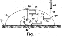
- device 10 is applied to the skin 15 of a subject.
- the device in this figure is self-contained, i.e., such that the device is able to function to withdraw blood from a subject to produce plasma or serum without requiring external connections such as an external source of vacuum, an external source of power, or the like. In other embodiments, however, the device need not be self-contained.
- flow activators 25 are deployed into skin 15 of the subject.
- the flow activators may include one or more needles or microneedles, or other flow activators as discussed in detail below. Copies of these documents are also included at the end of this application.
- the deployment of flow activators 25 into skin 15 of the subject may be accomplished using a deployment actuator 28, or by other techniques such as those described herein.
- the deployment actuator 28 may include suitable components to deploy the flow activators 25, such as a button, a switch, a lever, a slider, a dial, a compression spring, a Belleville spring, a servo, rotary or linear electric motor, and/or a pneumatic apparatus, or other suitable device.
- a vacuum or a reduced pressure less than atmospheric or ambient pressure may be used to facilitate the movement of blood 30 into the device, as follows.
- the vacuum may be contained within device 10, for example, within vacuum chamber 35.
- Blood 30 on the skin 15 of the subject may become exposed to the vacuum or reduced pressure, which causes the blood to enter device 10, e.g., through applicator region 40 into inlet 42 of channel 45, passing through membrane 50 towards storage chamber 33.
- Storage chamber 33 is located immediately on the other side of membrane 50 in this particular example, and can be used to collect plasma or serum that is produced by drawing blood 30 through membrane 50.
- Membrane 50 may be, for example, a separation membrane or a membrane that is permeable to fluids but is substantially impermeable to cells.
- Plasma or serum present within storage chamber 33 may be collected, e.g., for subsequent use and/or analysis.
- other components on the other side of membrane 50 may remain there, thereby forming a portion that is concentrated or enriched in blood cells, i.e., the concentration of blood cells in this portion may be higher than the initial concentration of blood cells in the blood received from the subject.
- blood spots may be produced on a blood spot membrane.
- channel 45 may have a small volume relative to the volume of a blood spot membrane which may be very porous and may collect fluid.
- the blood spot membrane is used to collect fluid.
- the blood spot membrane is not used to separate cells/plasma (as opposed to the separation membranes discussed earlier).
- Fluid may fill the blood spot membrane.
- a second hydrophobic membrane may be positioned on top of the collection membrane. Once fluid contacts the hydrophobic membrane, fluid collection ceases.
- the blood spot membrane may remain in the device to dry and is then removed from the device. Alternatively, the blood spot membrane may be removed from the device and dried outside of the device. In either case, vacuum is released prior to removal of the blood spot membrane.
- the plasma or serum may be removed from storage chamber 33 using any suitable technique.
- Any suitable technique One non-limiting example is now described. However, it should be understood that other techniques may be used instead of and/or in addition to the following, and that this technique may also be applied to remove blood (or other bodily fluids) from a device such as device 10, whether separation of the blood into plasma or serum has occurred or not. Examples of other suitable techniques are disclosed in U.S. Patent Application Serial No. 13/006,165, filed January 13,2011 , entitled "Sampling Device Interfaces," by Chickering, et al ..
- syringe 65 may be introduced through septum 60 to reach the storage chamber and/or a portion of the device that is in fluidic communication with storage chamber 33.
- syringe 65 may contain air, typically at atmospheric or ambient pressure, e.g., within needle 68 of syringe 65.
- the air may cause the plasma, serum, or other liquids to be moved or "blown" around the device, especially within storage chamber 33, and in some cases in a relatively uncontrolled fashion.
- vacuum chamber 35 may be separated from storage chamber 33 so that additional air can be introduced into device 10 without causing the plasma, serum, or other liquids within storage chamber 33 to be moved around within the device, e.g., exiting storage chamber 33.
- a second membrane 75 separates vacuum chamber 35 from storage chamber 33.
- Second membrane 75 may be selected so as to allow passage of gases but prevent the passage of liquids.
- second membrane 75 can be a relatively hydrophobic membrane, or a membrane that has a contact angle of at least 45° relative to an air/water interface. Other suitable membranes are discussed below.
- the present invention is generally directed to devices able to withdraw or extracting blood, interstitial fluid, or other bodily fluids from the skin of a subject, e.g., from the skin and/or from beneath the skin, or other mucosal surface, as well as methods of use thereof.
- the received fluid may be any suitable bodily fluid, such as interstitial fluid, other skin-associated material, mucosal material or fluid, whole blood, perspiration, saliva, plasma, serum, tears, lymph, urine, or any other bodily fluid, or combinations thereof.
- Substances received from a subject can include solid or semi-solid material such as skin, cells, or any other substance from the skin and/or beneath the skin of the subject.
- Substances that can be delivered to a subject in accordance with some embodiments of the invention include diagnostic substances, therapeutic substances such as drugs, and the like.
- Various embodiments of the invention are described below in the context of delivering or receiving a fluid, such as blood or interstitial fluid, from the skin and/or beneath the skin. It is to be understood that in all embodiments herein, regardless of the specific exemplary language used (e.g., withdrawing blood), the devices and methods of other embodiments of the invention can be used for receiving any substance from the skin and/or from beneath the skin of the subject, and/or for delivering any substance to the subject, e.g., to the skin and/or a location beneath the skin of the subject.
- the device may contain a flow activator (for example, one or more needles or microneedles). Examples of flow activators are discussed in detail below.
- the device may be used to pierce the skin of the subject, and fluid can then be delivered to and/or received from the skin of the subject.
- a flow activator for example, one or more needles or microneedles. Examples of flow activators are discussed in detail below.
- the device may be used to pierce the skin of the subject, and fluid can then be delivered to and/or received from the skin of the subject.
- references to withdrawing a fluid "from the skin” includes embodiments in which a fluid is delivered and/or received through the surface of the skin.
- a fluid may be delivered into or received from a layer of skin in one embodiment, while in another embodiment a fluid may be delivered into or received from a region just below the skin of the subject, e.g., passing through the surface of the skin, as opposed to other routes of administration such as oral delivery.
- the subject is usually human, although non-human subjects may be used in certain instances, for instance, other mammals such as a dog, a cat, a horse, a rabbit, a cow, a pig, a sheep, a goat, a rat (e.g., Rattus norvegicus ) , a mouse (e.g., Mus musculus), a guinea pig, a hamster, a primate (e.g., a monkey, a chimpanzee, a baboon, an ape, a gorilla, etc.), or the like.
- other mammals such as a dog, a cat, a horse, a rabbit, a cow, a pig, a sheep, a goat, a rat (e.g., Rattus norvegicus ) , a mouse (e.g., Mus musculus), a guinea pig, a hamster, a primate (e.
- blood received from a subject into a device may be separated within the device to form plasma or serum by passing the blood, or at least a portion thereof, through a separation membrane or a membrane that is permeable to fluids but is substantially impermeable to cells.
- the separation membrane can be any membrane able to separate blood passing therethrough into a first portion (passing through the membrane) that is enriched in plasma or serum, and a second portion (rejected by the membrane) concentrated in blood cells.
- the separation membrane may have a separation effectiveness during use (the separation effectiveness is the volume of plasma or serum that passes through the membrane relative to the starting volume of whole blood) of at least about 5%, at least about 10%, at least about 20%, at least about 40%, at least about 50%, at least about 55%, or at least about 60%.
- the separation membrane is selected to have a pore size smaller than the average or effective diameter of blood cells contained within the blood, including red blood cells and white blood cells.
- the pore size of the separation membrane may be less than about 30 micrometers, less than about 20 micrometers, less than about 10 micrometers, less than about 8 micrometers, less than about 6 micrometers, less than about 4 micrometers, less than about 3 micrometers, less than about 2 micrometers, less than about 1.5 micrometers, less than about 1 micrometer, less than about 0.5 micrometers, etc.
- the pore size may be between about 0.5 micrometers and about 2 micrometers, or between about 0.5 micrometers and about 1 micrometer.
- the separation membrane may have a thickness of less than about 1 mm, less than about 750 micrometers, less than about 500 micrometers, less than about 400 micrometers, less than about 350 micrometers, less than about 300 micrometers, less than about 250 micrometers, or less than about 200 micrometers.
- the separation membrane may be formed out of any suitable material.
- the separation membrane may be formed out of a material that promotes thrombolysis or inhibits clot formation, such as a polyester, and/or the separation membrane may be formed and/or coated with a biocompatible material, or at least a material that does not cause an active clotting response within the blood that the separation membrane is exposed to.
- the separation membrane can comprise or be formed from glass (e.g., glass fibers), and/or a polymer such as a polycarbonate, a polysulfone, a polyethersulfone, a polyarylethersulfone, a polyvinylpyrrolidone, a polypropylene, poly(2-methoxyethylacrylate), and/or a nitrocellulose, etc.
- the membrane may include a copolymer such as a graft copolymer (for example, poly(propylene-graft-2-methoxyethylacrylate)), e.g., including any one or more of these polymers and/or other suitable polymers.
- the separation membrane may be asymmetric, e.g., having a different separation effectiveness depending on which way blood is passed across the separation membrane to produce plasma.
- Many such separation membranes may be readily obtained commercially, such as Pall Vivid Plasma Separation Membrane (GF, GX, and GR), as well as other commercially available separation membranes.
- blood is moved towards the separation membrane using a suitable driving force to move the blood, for example, vacuum or other reduced pressure as is discussed herein.
- a fluidic portion of the blood is able to pass across the separation membrane to form plasma or serum on one side of the membrane, while other portions of the blood, e.g., red and white blood cells, are rejected by the membrane and thus form a portion that becomes concentrated in blood cells.
- serum may be produced if no anticoagulant is present, in accordance with certain embodiments.
- Either or both portions of the blood may be collected, e.g., in an appropriate storage chamber, for further use, analysis, storage, etc., as is discussed herein.
- blood may be drawn from a subject through an applicator region in the device.
- the applicator region may be positioned to collect a bodily fluid on the skin of the subject that is released by a flow activator.
- bodily fluids include blood or interstitial fluid, as is discussed herein.
- the flow activator may be applied to the skin, and optionally received from the skin, in order to cause the release of a bodily fluid to the applicator region of the device.
- a flow activator may include one or more needles or microneedles, a hygroscopic agent, etc., as is discussed herein.
- the flow activator can be centered with respect to the applicator region in certain embodiments; in other embodiments, however, the flow activator is not centered within the applicator region, and in some embodiments, the flow activator may not necessarily enter the applicator region.
- the applicator region may be any portion of the device that is sized and/or positioned to collect bodily fluids, and in some cases, the applicator region may have a relatively small size and/or volume.
- the volume of the applicator region is defined relative to the opening of the applicator region, or the portion of the applicator region that is adjacent the skin of the subject when the device is applied to the skin of the subject.
- the applicator region may be a recess or an indentation within the base of the device, which can receive a fluid from the surface of the skin.
- the applicator region may have any suitable shape.
- the applicator region can be generally hemispherical, semi-oval, rectangular, irregular, etc.
- the volume of the applicator region can be relatively small in some embodiments.
- the volume of the applicator region may be less than about 10 ml, less than about 8 ml, less than about 5 ml, less than about 3 ml, less than about 2 ml, less than about 1.5 ml, less than about 1 ml, less than about 800 microliters, less than about 600 microliters, less than about 500 microliters, less than about 400 microliters, less than about 300 microliters, less than about 200 microliters, or less than about 100 microliters. Smaller volumes may be desirable, for example, to minimize the amount of bodily fluid collected within the applicator region before the bodily fluid is able to be transported into the device, e.g., through an inlet within the applicator region into the device.
- the applicator region may have a small volume relative to a vacuum chamber contained within the device, e.g., in embodiments where a vacuum chamber is present in the device.
- the vacuum chamber may be a pre-packaged vacuum chamber as is discussed below.
- a relatively small applicator region will result in less gas being drawn into the vacuum chamber upon the creation of a fluid communication pathway between the vacuum source and the applicator region, e.g., as is discussed herein. This may allow more of the vacuum or reduced pressure to be able to draw more bodily fluid into the device.
- the ratio between the volume of the applicator region to the volume of the vacuum chamber can be at least about 1:5, at least about 1:8, at least about 1:10, at least about 1:12, at least about 1:15, etc.
- the applicator region may also contain one or more inlets for introduction of a bodily fluid from the subject into the device.
- the inlet can be an inlet to a fluid communication pathway, a channel such as a microfluidic channel, or the like, which may extend to the separation membrane, and/or to other portions of the device, e.g., such that fluids entering the inlet are able to reach the separation membrane, for example, under action of vacuum or reduced pressure being used to move the fluid towards the separation membrane.
- a fluid communication pathway a channel such as a microfluidic channel, or the like
- the fluid communication pathway into the device may proceed to, for example, a vacuum chamber, a storage or collection chamber, a separation membrane, a portion of the device containing a sensor, or the like, and/or one or more of these.
- a seal can be maniuplated to control the fluid communication pathway.
- the seal may be manipulated reversibly to open and close the fluid communication pathway.
- the seal may be a valve that can be opened and closed manually, automatically, with a machine, etc.
- the seal may also be manipulated irreversibly.
- the seal may be punctured to open the fluid communication pathway and unable to re-seal.
- the fluid communication pathway may include one or more microfluidic channels as discussed herein; for example, the fluid communication pathway may include one or more microfluidic channels having an average cross-sectional diameter of between about 100 and about 700 micrometers, or between about 300 and about 500 micrometers. Other examples of fluid communication pathways are discussed herein, including other channels and microfluidic channels.
- the inlet may be positioned in any suitable location within the applicator region, and one or more inlets may be present.
- an inlet (or at least a portion thereof) may be positioned relatively close to the skin of the subject.
- the inlet may be positioned such that at least a portion of the inlet is positioned within about 5 micrometers, within about 3 micrometers, within about 1 micrometer, within about 0.7 micrometers, within about 0.5 micrometers, or within about 0.3 micrometers of the skin or the opening of the applicator region.
- the inlet (or at least a portion thereof) may be positioned to be within about 50%, within about 30%, within about 20%, within about 10%, or within about 5% of the skin of the subject or the opening of the applicator region, where the percentage may be taken relative to the distance between the opening of the applicator region and a point within the applicator region perpendicularly furthest away from the opening.
- a seal or other suitable apparatus may be used to control a fluid communication pathway, for example, between the inlet and a vacuum chamber and/or a storage chamber.
- the seal may comprise a valve or a pierceable surface that can be opened.
- enabling fluid communication between a vacuum source and a fluid transporter opening need not necessarily involve the opening of a valve or other device that blocks flow, but instead may involve the creation of suitable vacuum to cause flow.
- the seal is reversible, i.e., the seal may also be used to end the fluid communication pathway (for example, a valve that can be opened or closed). In other embodiments, however, the seal is not reversible.
- the seal can be activated using any suitable technique, e.g., automatically, remotely, manually, etc.
- the seal may be self-activating, e.g., upon application to the skin of a subject.
- the seal may be activated once, or multiple times in some cases.
- the seal may be activated, for example, by pushing a button, flipping a switch, moving a slider, turning a dial, or the like.
- the subject, and/or another person may activate the seal.
- the seal, or at least a portion thereof may also serve as an activator, as discussed herein.
- Other examples of seals are discussed U.S. Provisional Patent Application Serial No. 61/480,977 , entitled “Delivering and/or Receiving Fluids," by Gonzales-Zugasti, et al ., filed on April 29,2011.
- a vacuum may be used to facilitate the withdraw of blood (or other bodily fluids) from the subject, and/or for causing the blood received from the subject to be separated within the device to form plasma or serum, and a portion concentrated in blood cells.
- the device may contain a suitable vacuum source.
- the vacuum source is one that is self-contained within the device, i.e., the device need not be connected to an external vacuum source (e.g., a house vacuum) during use of the device to withdraw blood, interstitial fluid, or other bodily fluids from the skin and/or from beneath the skin.
- relatively small vacuum chambers may be used, e.g., so that the device may have a relatively small size.
- the vacuum chamber may have a volume of less than about 25 ml, less than about 20 ml, less than about 15 ml, less than about 10 ml, less than about 5 ml, less than about 3 ml, less than about 2 ml, or less than about 1 ml.
- the vacuum source may include a vacuum chamber having a pressure less than atmospheric or ambient pressure before blood (or other fluid) is received into the device, i.e., the vacuum chamber is at a "negative pressure” (that is, negative relative to atmospheric or ambient pressure) or a "vacuum pressure” (or just having a “vacuum”).
- the vacuum in the vacuum chamber may be at least about 50 mmHg, at least about 100 mmHg, at least about 150 mmHg, at least about 200 mmHg, at least about 250 mmHg, at least about 300 mmHg, at least about 350 mmHg, at least about 400 mmHg, at least about 450 mmHg, at least about 500 mmHg, at least 550 mmHg, at least 600 mmHg, at least 650 mmHg, at least about 700 mmHg, or at least about 750 mmHg, i.e., below atmospheric or ambient pressure.
- the pressure within the vacuum is at a "reduced pressure" relative to atmospheric or ambient pressure, e.g., the vacuum chamber is a reduced pressure chamber.
- the vacuum chamber is a reduced pressure chamber.
- other pressures may be used and/or that different methods may be used to produce other pressures (greater than or less than atmospheric or ambient pressure).
- an external vacuum or a mechanical device may be used as the vacuum source; various additional examples are discussed in detail herein.
- the vacuum may be an external vacuum source, and/or the vacuum source may be self-contained within the device.
- vacuums of at least about 50 mmHg, at least about 100 mmHg, at least about 150 mmHg, at least about 200 mmHg, at least about 250 mmHg, at least about 300 mmHg, at least about 350 mmHg, at least about 400 mmHg, at least about 450 mmHg, at least about 500 mmHg, at least 550 mmHg, at least 600 mmHg, at least 650 mmHg, at least about 700 mmHg, or at least about 750 mmHg may be applied to the skin.
- vacuum refers to pressures that are below atmospheric or ambient pressure.
- the device may comprise an internal vacuum source, and/or be connectable to a vacuum source is external to the device, such as a vacuum pump or an external (line) vacuum source.
- vacuum may be created manually, e.g., by manipulating a syringe pump, a plunger, or the like, or the low pressure may be created mechanically or automatically, e.g., using a piston pump, a syringe, a bulb, a Venturi tube, manual (mouth) suction, etc., or the like.
- a device may be used to withdraw fluid using a vacuum without an external power and/or a vacuum source.
- vacuum examples include skin patches, strips, tapes, bandages, or the like.
- a skin patch may be contacted with the skin of a subject, and a vacuum created through a change in shape of a portion of the skin patch or other device (e.g., using a shape memory polymer), which may be used to deliver to and/or withdraw fluid from the skin and/or beneath the skin.
- a shape memory polymer may be shaped to be flat at a first temperature (e.g., room temperature) but curved at a second temperature (e.g., body temperature), and when applied to the skin, the shape memory polymer may alter from a flat shape to a curved shape, thereby creating a vacuum.
- a mechanical device may be used to create the vacuum, For example, springs, coils, expanding foam (e.g., from a compressed state), a shape memory polymer, shape memory metal, or the like may be stored in a compressed or wound state upon application to a subject, then released (e.g., unwinding, uncompressing, etc.), to mechanically create the vacuum.
- the device may be used to create a vacuum automatically, once activated, without any external control by a user.
- the device is "pre-packaged" with a suitable vacuum source (e.g., a pre-evacuated vacuum chamber); for instance, in one embodiment, the device may be applied to the skin and activated in some fashion to create and/or access the vacuum source.
- a chemical reaction may be used to create a vacuum, e.g., a reaction in which a gas is produced, which can be harnessed to provide the mechanical force to create a vacuum.
- a component of the device may be able to create a vacuum in the absence of mechanical force.
- the device may include a self-contained vacuum actuator, for example, chemical reactants, a deformable structure, a spring, a piston, etc.
- the device may be able to create a pressure differential (e.g. a vacuum).
- the device may contain a pressure differential chamber, such as a vacuum chamber or a pressurized chamber, that can be used to create a pressure differential.
- the pressure differential may be created by a pressure regulator.
- pressure regulator is a pressure controller component or system able to create a pressure differential between two or more locations.
- the pressure differential should be at least sufficient to urge or move fluid or other material in accordance with various embodiments of the invention as discussed herein, and the absolute pressures at the two or more locations are not important so long as their differential is appropriate, and their absolute values are reasonable for the purposes discussed herein.
- the pressure regulator may produce a pressure higher than atmospheric or ambient pressure in one location, relative to a lower pressure at another location (atmospheric or ambient pressure or some other pressure), where the differential between the pressures is sufficient to urge or move fluid in accordance with the invention.
- the regulator or controller will involve a pressure lower than atmospheric or ambient pressure (a vacuum) in one location, and a higher pressure at another location(s) (atmospheric or ambient pressure or a different pressure) where the differential between the pressures is sufficient to urge or move fluid in accordance with the invention.
- vacuum or "pressure”
- a vacuum chamber can be replaced in many instances with a pressure chamber, for creating a pressure differential suitable for urging the movement of fluid or other material.
- the pressure regulator may be an external source of vacuum (e.g. a lab, clinic, hospital, etc., house vacuum line or external vacuum pump), a mechanical device, a vacuum chamber, pre-packaged vacuum chamber, a pressurized chamber, or the like.
- vacuum may be created manually, e.g., by manipulating a syringe pump, a plunger, or the like, or the low pressure may be created mechanically or automatically, e.g., using a piston pump, a syringe, a bulb, a Venturi tube, manual (mouth) suction, etc., or the like.
- Vacuum chambers can be used in some embodiments, where the device contains, e.g., regions in which a vacuum exits or can be created (e.g. a variable volume chamber, a change in volume of which will affect vacuum or pressure).
- a vacuum chamber can include pre-evacuated (i.e., pre-packaged) chambers or regions, and/or self-contained actuators.
- a "self-contained" vacuum (or pressure) regulator means one that is associated with (e.g., on or within) the device, e.g. one that defines an integral part of the device, or is a separate component constructed and arranged to be specifically connectable to the particular device to form a pressure differential (i.e., not a connection to an external source of vacuum such as a hospital's, clinic's, or lab's house vacuum line, or a vacuum pump suitable for general use).
- the self-contained vacuum source may be actuated in some fashion to create a vacuum within the device.
- the self-contained vacuum source may include a piston, a syringe, a mechanical device such as a vacuum pump able to create a vacuum within the device, and/or chemicals or other reactants that can react to increase or decrease pressure which, with the assistance of mechanical or other means driven by the reaction, can form a pressure differential associated with a pressure regulator.
- Chemical reaction can also drive mechanical actuation with or without a change in pressure based on the chemical reaction itself.
- a self-contained vacuum source can also include an expandable foam, a shape memory material, or the like.
- One category of self-contained vacuum or pressure regulators of the invention includes self-contained assisted regulators. These are regulators that, upon actuation (e.g., the push of a button, or automatic actuation upon, e.g., removal from a package or urging a device against the skin), a vacuum or pressure associated with the device is formed where the force that pressurizes or evacuates a chamber is not the same as the actuation force.
- self-contained assisted regulators include chambers evacuated by expansion driven by a spring triggered by actuation, release of a shape-memory material or expandable material upon actuation, initiation of a chemical reaction upon actuation, or the like.
- Another category of self-contained vacuum or pressure regulators of the invention are devices that are not necessarily pre-packaged with pressure or vacuum, but which can be pressurized or evacuated, e.g. by a subject, health care professional at a hospital or clinic prior to use, e.g. by connecting a chamber of the device to a source of vacuum or pressure.
- the subject, or another person may actuate the device to create a pressure or vacuum within the device, for example, immediately prior to use of the device.
- the vacuum or pressure regulator may be a "pre-packaged" pressure or vacuum chamber in the device when used (i.e., the device can be provided ready for use by a subject or practitioner with an evacuated region on or in the device, without the need for any actuation to form the initial vacuum).
- a pre-packaged pressure or vacuum chamber regulator can, e.g., be a region evacuated (relative to atmospheric or ambient pressure) upon manufacture and/or at some point prior to the point at which it is used by a subject or practitioner. For example, a chamber is evacuated upon manufacture, or after manufacture but before delivery of the device to the user, e.g. the clinician or subject.
- the device contains a vacuum chamber having a vacuum of at least about 50 mmHg, at least about 100 mmHg, at least about 150 mmHg, at least about 200 mmHg, at least about 250 mmHg, at least about 300 mmHg, at least about 350 mmHg, at least about 400 mmHg, at least about 450 mmHg, at least about 500 mmHg, at least about 550 mmHg, at least about 600 mmHg, at least about 650 mmHg, at least about 700 mmHg, or at least about 750 mmHg below atmospheric or ambient pressure.
- a device of the present invention may not have an external power and/or a vacuum source.
- the device is "pre-loaded" with a suitable vacuum source; for instance, in one embodiment, the device may be applied to the skin and activated in some fashion to create and/or access the vacuum source.
- a device of the present invention may be contacted with the skin of a subject, and a vacuum created through a change in shape of a portion of the device (e.g., using a shape memory polymer), or the device may contain one or more sealed, self-contained vacuum chambers, where a seal is punctured in some manner to create a vacuum.
- a vacuum chamber may be in fluidic communication with one or more needles, and the reduced pressure can be used to move the skin towards the device, withdraw fluid from the skin and/or beneath the skin, or the like.
- a shape memory polymer may be shaped to be flat at a first temperature (e.g., room temperature) but curved at a second temperature (e.g., body temperature), and when applied to the skin, the shape memory polymer may alter from a flat shape to a curved shape, thereby creating a vacuum.
- a mechanical device may be used to create the vacuum, For example, springs, coils, expanding foam (e.g., from a compressed state), a shape memory polymer, shape memory metal, or the like may be stored in a compressed or wound released upon application to a subject, then released (e.g., unwinding, uncompressing, etc.), to mechanically create the vacuum.
- Non-limiting examples of shape-memory polymers and metals include Nitinol, compositions of oligo(epsilon-caprolactone)diol and crystallizable oligo(rho-dioxanone)diol, or compositions of oligo(epsilon-caprolactone)dimethacrylate and n -butyl acrylate.
- a chemical reaction may be used to create a vacuum, e.g., a reaction in which a gas is produced, which can be harnessed to provide the mechanical force to create a vacuum.
- the device may be used to create a vacuum automatically, once activated, without any external control by a user.
- the device contains a vacuum chamber that is also used as a storage chamber to receive blood, interstitial fluid, or other fluid received from the skin and/or beneath the skin of the subject into the device.
- a vacuum chamber that is also used as a storage chamber to receive blood, interstitial fluid, or other fluid received from the skin and/or beneath the skin of the subject into the device.
- blood received from a subject through or via the fluid transporter may enter the vacuum chamber due to its negative pressure (i.e., because the chamber has an internal pressure less than atmospheric or ambient pressure) to produce plasma or serum, and the blood, serum and/or plasma may be optionally stored in the device, e.g., within a storage or collection chamber, or within a vacuum chamber for later use.
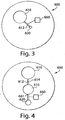
- a non-limiting example is illustrated in Fig. 3 .
- device 600 contains vacuum chamber 610, which is connected to flow activator 620 (which may be, e.g., one or more needles or microneedles).
- flow activator 620 which may be, e.g., one or more needles or microneedles.
- vacuum chamber 610 may be put into fluidic communication with flow activator 620.
- Flow activator 620 may accordingly cause negative pressure to be applied to the skin of the subject, for instance, due to the internal pressure within vacuum chamber 610.
- Blood received from the skin and/or beneath the skin via flow activator 620 may accordingly be drawn into the device and into vacuum chamber 610, e.g., through conduit 612.
- the blood may be passed across a separation membrane or a membrane that is permeable to fluids but is substantially impermeable to cells.
- the device may include separate vacuum chambers and storage chambers (e.g., chambers to store fluid such as blood, serum, or plasma from the skin and/or beneath the skin of the subject).
- the vacuum chamber and storage chambers may be in fluid communication, and may have any suitable arrangement.
- the vacuum from the vacuum chamber may be used, at least in part, to withdraw fluid from the skin and/or beneath the skin, which is then directed into a storage chamber, e.g., for later analysis or use, for example, as discussed below.
- blood may be received into the device, flowing towards a vacuum chamber, but the blood (or other fluid) may be prevented from entering the vacuum chamber.
- a material permeable to gas but not to a liquid such as blood or interstitial fluid may be used.
- the material may be a membrane such as a hydrophilic or hydrophobic membrane having a suitable porosity, a porous structure, a porous ceramic frit, a dissolvable interface (e.g., formed from a salt or a polymer, etc.), or the like.
- device 600 contains vacuum chamber 610 and storage chamber 615.
- Vacuum chamber 610 can be put in fluidic communication with storage chamber 615 via conduit 612, which contains material 614.
- Material 614 may be any material permeable to gas but not to a liquid in this example, e.g., material 614 may be a membrane such as a hydrophilic membrane or a hydrophobic membrane that has a porosity that allows gas exchange to occur but does not.allow the passage of blood or interstitial fluid from the skin and/or beneath the skin of the subject.
- the needle may be used for delivering to and/or receiving fluids or other materials from a subject, e.g., to or from the skin and/or beneath the skin.
- a vacuum chamber having a reduced pressure or an internal pressure less than atmospheric or ambient pressure prior to receiving blood or other bodily fluids (e.g., interstitial fluid) may be used to assist in the receiving of the fluid from the skin after the needle (or other flow activator) has penetrated the skin.
- the fluid received from the skin and/or beneath the skin may be collected in the vacuum chamber and/or in a storage chamber.
- the storage chamber may be separated from the vacuum chamber using a gas permeable membrane (e.g., one that is substantially impermeable to blood or other bodily fluids), a hydrophobic membrane, a hydrophilic membrane, a porous structure, a dissolvable interface, or the like, e.g., as is discussed herein.
- a gas permeable membrane e.g., one that is substantially impermeable to blood or other bodily fluids
- a hydrophobic membrane e.g., one that is substantially impermeable to blood or other bodily fluids
- hydrophilic membrane e.g., one that is substantially impermeable to blood or other bodily fluids
- porous structure e.g., as is discussed herein.
- the flow of blood (or other fluid, e.g., interstitial fluid) into the storage chamber may be controlled using a flow controller.
- the flow controller may be manually and/or automatically controlled to control the flow of blood.
- the flow controller may activate or deactivate when a certain amount or volume of fluid has entered the storage chamber in certain cases. For instance, the flow controller may stop blood flow after a predetermined amount or volume of blood has entered the storage chamber, and/or the flow controller may be able to control the internal pressure of the storage chamber, e.g., to a specific level, such as a predetermined level.
- suitable flow controllers for the device include, but are not limited to, a membrane, a valve, a dissolvable interface, a gate, or the like.
- device 600 includes a vacuum chamber 610 and a storage chamber 615. Fluid entering device 600 via flow activator 620 is prevented from entering storage chamber 615 due to flow controller 645 present within conduit 611. However, under suitable conditions, flow controller 645 may be opened, thereby allowing at least some fluid to enter storage chamber 615. In some cases, for instance, storage chamber 615 also contains at least a partial vacuum, although this vacuum may be greater or less than the pressure within chamber 610. In other embodiments, flow controller 645 may initially be open, or be externally controllable (e.g., via an actuator), or the like. In some cases, the flow controller may control the flow of fluid into the device such that, after collection, at least some vacuum is still present in the device.
- the device may be constructed and arranged to reproducibly obtain from the skin and/or from beneath the skin of the subject a controlled amount of fluid, e.g., a controlled amount or volume of blood or interstitial fluid.
- the amount of fluid reproducibly obtained from the skin and/or beneath the skin of the subject may be controlled, for example, using flow controllers, materials permeable to gas but not to liquids, membranes, valves, pumps, gates, microfluidic systems, or the like, as discussed herein.
- the volume of blood or other fluid obtained from the skin and/or beneath the skin of the subject need not be strictly a function of the initial vacuum pressure or volume within the device.
- a flow controller may initially be opened (e.g., manually, automatically, electronically, etc.) to allow fluid to begin entering the device; and when a predetermined condition is reached (e.g., when a certain volume or amount of blood or interstitial fluid has entered the device), the flow controller maybe closed at that point, even if some vacuum remains within the device.
- a predetermined condition e.g., when a certain volume or amount of blood or interstitial fluid has entered the device
- this control of fluid allows the amount of fluid reproducibly obtained from the skin and/or beneath the skin of the subject to be controlled to a great extent.
- the amount of fluid received from the skin and/or beneath the skin of the subject may be controlled to be less than about 1 ml, may be less than about 300 microliters, less than about 200 microliters, less than about 100 microliters, less than about 50 microliters, less than about 30 microliters, less than about 20 microliters, less than about 10 microliters, less than about 5 microliters, less than about 3 microliters, less than about 2 microliters, less than about 1 microliter, etc.
- the device may be connected to an external apparatus for determining at least a portion of the device, a fluid (e.g., plasma or serum) removed from the device, an analyte suspected of being present within the fluid, or the like.
- a fluid e.g., plasma or serum
- the device may be connected to an external analytical apparatus, and fluid removed from the device for later analysis, or the fluid may be analyzed within the device in situ, e.g., by adding one or more reaction entities to the device, for instance, to a storage chamber, or to analytical chamber within the device.
- the external apparatus may have a port or other suitable surface for mating with a port or other suitable surface on the device, and blood, interstitial fluid, or other fluid can be removed from the device using any suitable technique, e.g., using vacuum or pressure, etc.
- the blood or other fluid may be removed by the external apparatus, and optionally, stored and/or analyzed in some fashion.
- the device may include an exit port for removing a fluid from the device (e.g., blood).
- fluid contained within a storage chamber in the device may be removed from the device, and stored for later use or analyzed outside of the device.
- the exit port may be separate from the flow activator.
- exit port 670 and flow activator 620 in device 600 in Fig. 6 An example is shown with exit port 670 and flow activator 620 in device 600 in Fig. 6 .
- the exit port can be in fluidic communication with vacuum chamber 610.
- an exit port can be in fluidic communication with a vacuum chamber, which can also serve as a fluid reservoir in some cases.
- Other methods for removing blood, interstitial fluid, or other fluids from the device include, but are not limited to, removal using a vacuum line, a pipette, extraction through a septum instead of an exit port, or the like.
- the device may also be positioned in a centrifuge and subjected to various g forces (e.g., to a centripetal force of at least 50 g), e.g., to cause at separation of cells or other substances within a fluid within the device to occur.
- various g forces e.g., to a centripetal force of at least 50 g
- the liquid may be blood, plasma, serum, or other fluids contained within the device.
- a liquid such as plasma or serum may be removed from a storage chamber within the device.
- the storage chamber may also be a vacuum chamber, or the storage chamber may be one that is at least partially separated from a vacuum chamber, for example, by a membrane.
- a seal can be used to control a fluid communication pathway between the vacuum chamber and the storage chamber.
- a storage chamber containing a fluid such as plasma or serum can be in gaseous communication with the vacuum chamber, e.g., such that the pressures within the storage chamber and the vacuum chamber are substantially equal.
- the storage chamber and the vacuum chamber may not necessarily be in liquid communication with each other, for example, due to the presence of a membrane or other structure (e.g., a retaining wall) separating the storage chamber and the vacuum chamber.
- a membrane e.g., a retaining wall
- the membrane can be, for example, a hydrophobic membrane, or a membrane that is gas permeable but is substantially liquid impermeable.
- a needle e.g., of a syringe
- a needle may be inserted through a septum or other pierceable material into the storage chamber, and/or to a portion of the device in fluidic communication with the storage chamber, e.g., such that the needle can access a liquid within the storage chamber or in fluidic communication with the storage chamber.
- the needle may be inserted, e.g., manually or automatically by an external apparatus, e.g., as is described herein.
- the septum or other pierceable material may comprise, for example, silicone or another suitable material, and in some cases, can be re-sealed once the needle has been removed, e.g., to maintain the pressure within the device at a vacuum or reduced pressure.
- the needle can contain some residual gas (typically air).
- the gas from within the needle may be introduced into the device, e.g., into the storage chamber.
- the pressure of the gas within the needle is greater than the pressure within the storage chamber, and the difference in pressure and the introduction of gas from the needle into the storage chamber may cause liquids within the storage chamber to move within the device.
- the movement or flow of the liquids may be relatively uncontrolled within the device as the pressures within the device reequalize due to the presence of the needle and the gases contained therein.
- one or more membranes may be used to at least partially confine liquids within the storage chamber such that the liquids do not move around the device, and/or are permitted to only move around certain portions of the device, while gases may be permitted to move within the device, e.g., to substantially equalize pressures within the device.
- one or more membranes or other suitable structures may be used to contain a liquid, such as plasma or serum, within the storage chamber.
- the membranes may be selected, for example, to be substantially hydrophobic, and/or such that the membrane is gas permeable but is substantially liquid impermeable.
- the membrane may be selected to have a pore size that allows gaseous exchange to occur but is too small to allow substantial liquid penetration to occur (e.g., due to capillary action).
- the membrane may have a pore size of less than about 1000 micrometers, less than about 500 micrometers, less than about 300 micrometers, less than about 100 micrometers, less than about 50 micrometers, less than about 30 micrometers, less than about 10 micrometers, less than about 5 micrometers, less than about 3 micrometers, or less than about 1 micrometer.
- the membrane may be chosen to be substantially hydrophobic, e.g., if the liquid contained within the storage chamber is aqueous or hydrophilic.
- the hydrophobic membrane may exhibit a water/air contact angle of at least about 45° or at least about 90°.
- the membrane may be formed out of any suitable material.
- the membrane may include a polymer such as a copolymer.
- the membrane may include one or more polymers such as a polyamide, a polypropylene, a polyvinyl chloride, a polyvinylacetate, a nylon, a polyvinylidene fluoride (PVDF), a polytetrafluoroethylene (PTFE), acrylic, unsaturated polyester (UPE), or the like.
- polymeric membranes may be readily obtained commercially, such as Millipore Fluoropore PTFE, Sterlitech NY125P, Pall Versapor (e.g., 450R or 800R), Millipore SureVent DVSP, Millipore SureVent DOHP, Millipore SureVent UPHP, or any other suitable polymeric membrane.
- Millipore Fluoropore PTFE Sterlitech NY125P
- Pall Versapor e.g., 450R or 800R
- Millipore SureVent DVSP Millipore SureVent DOHP
- Millipore SureVent UPHP Millipore SureVent UPHP
- the membrane may be chosen to have an air flow rate of at least about 0.25 liter/(min cm 2 psi), and in some cases, at least about 0.275 liter/(min cm 2 psi), at least about 0.3 liter/(min cm 2 psi), at least about 0.4 liter/(min cm 2 psi), at least about 0.5 liter/(min cm 2 psi), at least about 0.6 liter/(min cm 2 psi), at least about 0.7 liter/(min cm 2 psi), at least about 0.8 liter/(min cm 2 psi), at least about 0.9 liter/(min cm 2 psi), at least about 1 liter/(min cm 2 psi), at least about 1.1 liter/(min cm 2 psi), at least about 1.2 liter/(min cm 2 psi), at least about 1.3 liter/(min cm 2 psi), or at least about 1.4 liter/(min cm 2 psi
- a membrane having a relatively high bubble point is desired, e.g., a bubble point of at least about 5 psi, at least about 10 psi, or at least about 15 psi as measured for either water or blood.
- the membrane may be used to form one or more surfaces defining the chamber for at least partially confining the liquid.
- the top surface 205 of chamber 202 is formed from such membranes, and when liquid 212 enters chamber 202 (e.g., from below), air (or other gases) can leave through the top surface, as is indicated by arrows 210.
- all of the surfaces 205, 207 of chamber 202 are formed from such membranes, thereby allowing air (or other gases) to leave from any or all of these surfaces, as indicated by arrows 210.
- Fig. 10 illustrates chambers having cylindrical configurations, this is by way of example only, and in other embodiments, other chamber configurations may be used, e.g., rectangular, cubical, spherical, etc.
- device 10 includes a storage chamber 33 containing a liquid therein 31 to be removed, for example, blood, plasma, serum, interstitial fluid, or the like.
- membrane 50 may be present, which prevents liquid 31 from exiting storage chamber 33 through channel 45.
- Channel 45 may be, for example, a channel through which liquid 31 initially entered into storage chamber 33.
- other suitable systems may be used to prevent liquid 31 from exiting storage chamber 33 through channel 45, for example, a valve such as a check valve or a flap valve, a gate, a pump, etc., may be used, such as described herein.
- vacuum chamber 70 which may be in gaseous communication with storage chamber 33, e.g., via membrane 75. Due to the presence of membrane 75, gases are able to pass between vacuum chamber 70 and storage chamber 33, although liquids such as liquid 31 are not able to enter vacuum chamber 70.
- Fig. 2A also shows needle 68, which may be used to withdraw liquid 31 from storage chamber 33.
- Needle 68 is to be inserted into device 10 through septum 60 into storage chamber 33 and/or into a portion of device 10 that is in fluidic or liquid communication with the liquid within storage chamber 33, as is shown in this figure.
- needle 68 may contain a gas, typically air, which may be at atmospheric or ambient pressure. This pressure may be greater than the pressure within storage chamber 33. Accordingly, once needle 68 is inserted into septum 60, the gas within needle 68 is able to leave needle 68 and enter storage chamber 33.
- the gas in some embodiments may leave needle 68 relatively violently or in an uncontrolled fashion, thereby "blowing around" liquid 31 within storage chamber 33, as is shown representatively in Fig. 2B .
- liquid 31 within storage chamber 33 is unable to leave the storage chamber, while gases are able to leave, e.g., entering vacuum chamber 70, until the pressures within needle 68, storage chamber 33, and vacuum chamber 70 have substantially equalized, so that liquid 31 no longer is moved or "blown around” due to any pressure imbalances within the device. Liquid 31 can then be drawn into needle 68 to be removed from device 10, as is shown in Fig. 2C .
- the device includes a fluid transporter able to withdraw fluid from the skin and/or beneath the skin of the subject into the device.
- fluid transporter is any component or combination of components that facilitates movement of a fluid from one portion of the device to another, and/or from the device to the skin of the subject or vice versa.
- a fluid transporter can be or include a hollow needle or a solid needle, or other flow activator, and/or a region (applicator region) into which blood or other fluid is introduced.
- the flow activator may include a moveable mechanism, e.g., to move a needle, or may not require movement to function.
- the flow activator may include a jet injector or a "hypospray" that delivers fluid under pressure to a subject, a pneumatic system that delivers and/or receives fluid, a hygroscopic agent that adsorbs or absorbs fluid, a reverse iontophoresis system, a transducer that emits ultrasonic waves, or thermal, radiofrequency and/or laser energy, and so on, any of which need not necessarily require movement of a flow activator to cause fluid release from a subject.
- a solid needle is used, and fluid migrates along the needle due to surface forces (e.g., capillary action), then the solid needle can be at least a part of a fluid transporter. If fluid (e.g.
- the enclosure can define a fluid transporter.
- the fluid transporter may include an applicator region such as is described herein (with or without a needle or other flow activator therein).
- Other components including partially or fully enclosed channels, microfluidic channels, tubes, wicking members, vacuum containers, etc. can be fluid transporters.
- the fluid may be received from and/or through the skin of a subject (or other mucosal surface).
- the fluid transporter may be, for example, one or more needles and/or microneedles, a hygroscopic agent, a cutter or other piercing element, an electrically-assisted system, or the like, e.g., as discussed in detail herein. If needles or microneedles are used, they may be solid or hollow, i.e., blood, interstitial fluid, or other fluid may travel in and/or around the needles or microneedles into the device.
- the needles or microneedles may also be removed from the skin of the subject, e.g., after insertion into the skin, for example, to increase the flow of blood or other fluids from the skin and/or beneath the skin of the subject.
- one or more needles or microneedles may be inserted into the skin and removed, and then a pressure gradient or a vacuum may be applied to the skin to withdraw a fluid, such as blood or interstitial fluid.
- the flow activator includes solid needles that are removed from the skin and a cup or channel may be used to direct the flow of blood or other bodily fluids.
- Non-limiting examples of flow activators include one or more needles and/or microneedles, a hygroscopic agent, a cutter or other piercing element, an electrically-assisted system, or any other systems as described herein. Additional examples of such techniques are described herein. It is to be understood that, generally, fluids may be received in a variety of ways, and various systems and methods for receiving fluid from the skin and/or beneath the skin are discussed below.
- techniques for piercing or altering the surface of the skin to transport a fluid are discussed, for example, using a needle such as a hypodermic needle or one or more microneedles, chemicals applied to the skin (e.g., penetration enhancers), jet injectors or other techniques such as those discussed below.
- a needle such as a hypodermic needle or one or more microneedles
- chemicals applied to the skin e.g., penetration enhancers
- jet injectors e.g., jet injectors or other techniques such as those discussed below.
- a needle such as a hypodermic needle can be used to withdraw fluid to or from the skin and/or beneath the skin.
- Hypodermic needles are well-known to those of ordinary skill in the art, and can be obtained commercially with a range of needle gauges.
- the needle may be in the 20-30 gauge range, or the needle may be 32 gauge, 33 gauge, 34 gauge, etc.
- needles there may be one or more needles, the needles may be of any suitable size and length, and the needles may each be solid or hollow.
- the needles may have any suitable cross-section (e.g., perpendicular to the direction of penetration), for example, circular, square, oval, elliptical, rectangular, rounded rectangle, triangular, polygonal, hexagonal, irregular, etc.
- the needle may have a length of less than about 5 mm, less than about 4 mm, less than about 3 mm, less than about 2 mm, less than about 1 mm, less than about 800 micrometers, less than 600 micrometers, less than 500 micrometers, less than 400 micrometers, less than about 300 micrometers, less than about 200 micrometers, less than about 175 micrometers, less than about 150 micrometers, less than about 125 micrometers, less than about 100 micrometers, less than about 75 micrometers, less than about 50 micrometers, less than about 10 micrometers, etc.
- the needle may also have a largest cross-sectional dimension of less than about 5 mm, less than about 4 mm, less than about 3 mm, less than about 2 mm, less than about 1 mm, less than about 800 micrometers, less than 600 micrometers, less than 500 micrometers, less than 400 micrometers, less than about 300 micrometers, less than about 200 micrometers, less than about 175 micrometers, less than about 150 micrometers, less than about 125 micrometers, less than about 100 micrometers, less than about 75 micrometers, less than about 50 micrometers, less than about 10 micrometers, etc.
- the needle may have a rectangular cross section having dimensions of 175 micrometers by 50 micrometers.
- the needle may have an aspect ratio of length to largest cross-sectional dimension of at least about 2:1, at least about 3:1, at least about 4:1, at least 5:1, at least about 7:1, at least about 10:1, at least about 15:1, at least about 20:1, at least about 25:1, at least about 30:1, etc.
- the needle is a microneedle.
- a microneedle will have an average cross-sectional dimension (e.g., diameter) of less than about a millimeter.
- microneedles such as those disclosed in U.S. Patent No. 6,334,856, issued January 1, 2002 , entitled “Microneedle Devices and Methods of Manufacture and Use Thereof," by Allen, et al. , may be used to withdraw fluids (or other materials) from a subject.
- the microneedles may be hollow or solid, and may be formed from any suitable material, e.g., metals, ceramics, semiconductors, organics, polymers, and/or composites.
- Examples include, but are not limited to, medical grade stainless steel, titanium, nickel, iron, gold, tin, chromium, copper, alloys of these or other metals, silicon, silicon dioxide, and polymers, including polymers of hydroxy acids such as lactic acid and glycolic acid polylactide, polyglycolide, polylactide-co-glycolide, and copolymers with polyethylene glycol, polyanhydrides, polyorthoesters, polyurethanes, polybutyric acid, polyvaleric acid, polylactide-co-caprolactone, polycarbonate, polymethacrylic acid, polyethylenevinyl acetate, polytetrafluorethylene, polymethyl methacrylate, polyacrylic acid, or polyesters.
- polymers of hydroxy acids such as lactic acid and glycolic acid polylactide, polyglycolide, polylactide-co-glycolide, and copolymers with polyethylene glycol, polyanhydrides, polyorthoesters, polyurethane
- more than one needle or microneedle may be used.
- arrays of needles or microneedles may be used, and the needles or microneedles may be arranged in the array in any suitable configuration, e.g., periodic, random, etc.
- the array may have 3 or more, 4 or more, 5 or more, 6 or more, 10 or more, 15 or more, 20 or more, 35 or more, 50 or more, 100 or more, or any other suitable number of needles or microneedles.
- the device may have at least 3 but no more than 5 needles or microneedles (or other flow activators), at least 6 but no more than 10 needles or microneedles, or at least 11 but no more than 20 needles or microneedles.
- a microneedle will have an average cross-sectional dimension (e.g., diameter) of less than about a micron.
- needles relative to the skin for these purposes including, in one embodiment, introducing needles into the skin at an angle, relative to the skin's surface, other than 90°, i.e., to introduce a needle or needles into the skin in a slanting fashion so as to limit the depth of penetration. In another embodiment, however, the needles may enter the skin at approximately 90°.
- the needles may be present in an array selected such that the density of needles within the array is between about 0.5 needles/mm 2 and about 10 needles/mm 2 , and in some cases, the density may be between about 0.6 needles/mm 2 and about 5 needles/mm 2 , between about 0.8 needles/mm 2 and about 3 needles/mm 2 , between about 1 needles/mm 2 and about 2.5 needles/mm 2 , or the like.
- the needles may be positioned within the array such that no two needles are closer than about 1 mm, about 0.9 mm, about 0.8 mm, about 0.7 mm, about 0.6 mm, about 0.5 mm, about 0.4 mm, about 0.3 mm, about 0.2 mm, about 0.1 mm, about 0.05 mm, about 0.03 mm, about 0.01 mm, etc.
- the needles may be chosen such that the area of the needles (determined by determining the area of penetration or perforation on the surface of the skin of the subject by the needles) allows for adequate flow of fluid to or from the skin and/or beneath the skin of the subject.
- the needles may be chosen to have smaller or larger areas (or smaller or large diameters), so long as the area of contact for the needles to the skin is sufficient to allow adequate blood flow from the skin of the subject to the device.
- the needles may be selected to have a combined skin-penetration area of at least about 500 nm 2 , at least about 1,000 nm 2 , at least about 3,000 nm 2 , at least about 10,000 nm 2 , at least about 30,000 nm 2 , at least about 100,000 nm 2 , at least about 300,000 nm 2 , at least about 1 microns 2 , at least about 3 microns 2 , at least about 10 microns 2 , at least about 30 microns 2 , at least about 100 microns 2 , at least about 300 microns 2 , at least about 500 microns 2 , at least about 1,000 microns 2 , at least about 2,000 microns 2 , at least about 2,500 microns 2 , at least about 3,000 microns 2 , at least about 5,000 microns 2 , at least about 8,000 microns 2 , at least about 10,000 microns 2 , at least about 35,000 microns 2 ,
- the needles or microneedles may have any suitable length, and the length may be, in some cases, dependent on the application. For example, needles designed to only penetrate the epidermis may be shorter than needles designed to also penetrate the dermis, or to extend beneath the dermis or the skin.
- the needles or microneedles may have a maximum penetration into the skin of no more than about 3 mm, no more than about 2 mm, no more than about 1.75 mm, no more than about 1.5 mm, no more than about 1.25 mm, no more than about 1 mm, no more than about 900 microns, no more than about 800 microns, no more than about 750 microns, no more than about 600 microns, no more than about 500 microns, no more than about 400 microns, no more than about 300 microns, no more than about 200 microns, no more than about 175 micrometers, no more than about 150 micrometers, no more than about 125 micrometers, no more than about 100 micrometers, no more than about 75 micrometers, no more than about 50 micrometers, etc.
- the needles or microneedles may be selected so as to have a maximum penetration into the skin of at least about 50 micrometers, at least about 100 micrometers, at least about 300 micrometers, at least about 500 micrometers, at least about 1 mm, at least about 2 mm, at least about 3 mm, etc.
- the needles may be coated.
- the needles may be coated with a substance that is delivered when the needles are inserted into the skin.
- the coating may comprise heparin, an anticoagulant, an anti-inflammatory compound, an analgesic, an anti-histamine compound, etc. to assist with the flow of blood from the skin of the subject, or the coating may comprise a drug or other therapeutic agent such as those described herein.
- the drug or other therapeutic agent may be one used for localized delivery (e.g., of or proximate the region to which the coated needles or microneedles are applied), and/or the drug or other therapeutic agent may be one intended for systemic delivery within the subject.
- the fluid is received manually, e.g., by manipulating a plunger on a syringe.
- the fluid can be received from the skin and/or beneath the skin mechanically or automatically, e.g., using a piston pump or the like.
- Fluid may also be received using vacuums such as those discussed herein.
- vacuum may be applied to a conduit, such as a needle, in fluidic communication with a bodily fluid in order to draw up at least a portion of the fluid from the skin.
- fluid is received using capillary action (e.g., using a microfluidic channel or hypodermic needle having a suitably narrow inner diameter).
- pressure may be applied to force fluid out of the needle.
- fluid may be received using a hygroscopic agent applied to the surface of the skin or proximate the skin.
- a device as described herein may contain a hygroscopic agent.
- pressure may be applied to drive the hygroscopic agent into the skin.
- Hygroscopic agents typically are able to attract water from the surrounding environment, for instance, through absorption or adsorption.
- Non-limiting examples of hygroscopic agents include sugar, honey, glycerol, ethanol, methanol, sulfuric acid, methamphetamine, iodine, many chloride and hydroxide salts, and a variety of other substances.
- hygroscopic agent may be chosen based on its physical or reactive properties, e.g., inertness or biocompatibility towards the skin of the subject, depending on the application.
- the device may comprise a cutter able to cut or pierce the surface of the skin.
- the cutter may comprise any mechanism able to create a path through which fluids may be received from the skin and/or beneath the skin.
- the cutter may comprise a hypodermic needle, a blade (e.g., a knife blade, a serrated blade, etc.), a piercing element (e.g., a lancet or a solid or a hollow needle), or the like, which can be applied to the skin to create a suitable conduit for the receiving of fluid from the skin and/or from beneath the skin.
- a cutter is used to create such a pathway and removed, then fluid may be received via this pathway.
- the cutter remains in place within the skin, and fluid may be received through a conduit within the cutter.
- fluid may be received using an electric charge.
- reverse iontophoresis may be used.
- reverse iontophoresis uses a small electric current to drive charged and highly polar compounds across the skin. Since the skin is negatively charged at physiologic pH, it acts as a permselective membrane to cations, and the passage of counterions across the skin induces an electroosmotic solvent flow that may carry neutral molecules in the anode-to-cathode direction. Components in the solvent flow may be analyzed as described elsewhere herein.
- a reverse iontophoresis apparatus may comprise an anode cell and a cathode cell, each in contact with the skin.
- the anode cell may be filled, for example, with an aqueous buffer solution (i.e., aqueous Tris buffer) having a pH greater than 4 and an electrolyte (i.e. sodium chloride).
- the cathode cell can be filled with aqueous buffer.
- a first electrode e.g., an anode
- a second electrode e.g., a cathode
- the electrodes are not in direct contact with the skin.
- a current may be applied to induce reverse iontophoresis, thereby withdrawing a fluid from the skin.
- the current applied may be, for example, greater than 0.01 mA, greater than 0.3 mA, greater than 0.1 mA, greater than 0.3 mA, greater than 0.5 mA, or greater than 1 mA. It should be understood that currents outside these ranges may be used as well.
- the current may be applied for a set period of time. For example, the current may be applied for greater. than 30 seconds, greater than 1 minute, greater than 5 minutes, greater than 30 minutes, greater than 1 hour, greater than 2 hours, or greater than 5 hours. It should be understood that times outside these ranges may be used as well.
- the device may comprise an apparatus for ablating the skin.
- ablation comprises removing a microscopic patch of stratum corneum (i.e., ablation forms a micropore), thus allowing access to bodily fluids.
- thermal, radiofrequency, and/or laser energy may be used for ablation.
- thermal ablation may be applied using a heating element.
- Radiofrequency ablation may be carried out using a frequency and energy capable of heating water and/or tissue.
- a laser may also be used to irradiate a location on the skin to remove a portion.
- the heat may be applied in pulses such that a steep temperature gradient exists essentially perpendicular to the surface of the skin.
- a temperature of at least 100 °C, at least 200 °C, at least 300 °C, or at least 400 °C may be applied for less than 1 second, less than 0.1 seconds, less than 0.01 seconds, less than 0.005 seconds, or less than 0.001 seconds.
- the device may comprise a mechanism for taking a solid sample of tissue.
- a solid tissue sample may be acquired by methods such as scraping the skin or cutting out a portion.
- Scraping may comprise a reciprocating action whereby an instrument is scraped along the surface of the skin in two or more directions.
- Scraping can also be accomplished by a rotating action, for example parallel to the surface of the skin and in one direction (i.e., with a roller drum) or parallel to the surface of the skin and in a circular manner (i.e., with a drilling instrument).
- a cutting mechanism may comprise a blade capable of making one or more incisions and a mechanism for removing a portion of tissue (i.e., by suction or mechanically picking up) or may use a pincer mechanism for cutting out a portion of tissue.
- a cutting mechanism may also function by a coring action. For example, a hollow cylindrical device can be penetrated into the skin such that a cylindrical core of tissue may be removed.
- a solid sample may be analyzed directly or may be liquefied prior to analysis. Liquefaction can comprise treatment with organic solvents, enzymatic solutions, surfactants, etc.
- the flow activator may be fastened on a support structure.
- the support structure can bring the flow activator to the skin, and in certain instances, insert the fluid transport into the skin.
- the flow activator can be moved mechanically, electrically (e.g., with the aid of a servo, which may be computer-controlled), pneumatically, via a piston, a screw, a mechanical linkage, or the like.
- the support structure can insert the flow activator into the skin at a speed of at least about 0.1 cm/s, at least about 0.3 cm/s, about 1 cm/s, at least about 3 cm/s, at least about 10 cm/s, at least about 30 cm/s, at least about 1 m/s, at least about 2 m/s, at least about 3 m/s, at least about 4 m/s, at least about 5 m/s, at least about 6 m/s, at least about 7 m/s, at least about 8 m/s, at least about 9 m/s, at least about 10 m/s, at least about 12 m/s, etc., at the point where the flow activator initially contacts the skin.
- relatively faster insertion speeds may increase the ability of the flow activator to penetrate the skin (without deforming the skin or causing the skin to move in response), and/or decrease the amount of pain felt by the application of the flow activator to the skin.
- Any suitable method of controlling the penetration speed into the skin may be used, include those described herein.
- the device may include a support structure for application to the skin of the subject.
- the support structure may be used, as discussed herein, for applying the flow activator to the surface of the skin of the subject, e.g., so that fluid may be received from the skin and/or beneath the skin of the subject.
- the support structure may immobilize the flow activator such that the flow activator cannot move relative to the support structure; in other cases, however, the flow activator may be able to move relative to the support structure.
- the flow activator is immobilized relative to the support structure, and the support structure is positioned within the device such that application of the device to the skin causes at least a portion of the flow activator to pierce the skin of the subject.
- the support structure includes a reversibly deformable structure.
- the support structure may move from a first position to a second position.
- the first position may be one where the support structure has immobilized relative thereto a flow activator that does not contact the skin (e.g., the flow activator may be contained within a recess), while the second position may be one where the flow activator does contact the skin, and in some cases, the flow activator may pierce the skin.
- the support structure may be moved using any suitable technique, e.g., manually, mechanically, electromagnetically, using a servo mechanism, or the like.
- the support structure may be moved from a first position to a second position by pushing a button on the device, which causes the support structure to move (either directly, or indirectly, e.g., through a mechanism linking the button with the support structure).
- Other mechanisms e.g., dials, levers, sliders, etc., as discussed herein
- the support structure may be moved from a first position to a second position automatically, for example, upon activation by a computer, upon remote activation, after a period of time has elapsed, or the like.
- a servo connected to the support structure is activated electronically, moving the support structure from the first position to the second position.
- the support structure may also be moved from the second position to the first position. For example, after fluid has been received from the skin and/or beneath the skin, e.g., using a flow activator the support structure may be moved, which may move the flow activator away from contact with the skin.
- the support structure may be moved from the second position to the first position using any suitable technique, including those described above, and the technique for moving the support structure from the second position to the first position may be the same or different as that moving the support structure from the first position to the second position.
- the device may include a flexible concave member or a reversibly deformable structure that is moveable between a first configuration and a second configuration.
- the first configuration may have a concave shape, such as a dome shape
- the second configuration may have a different shape, for example, a deformed shape (e.g., a "squashed dome"), a convex shape, an inverted concave shape, or the like.
- the flexible concave member (or a reversibly deformable structure) may be moved between the first configuration and the second configuration manually, e.g., by pushing on the flexible concave member using a hand or a finger, and/or the flexible concave member may be moved using an actuator such as is described herein.
- the flexible concave member may be able to spontaneously return from the second configuration back to the first configuration.
- the flexible concave member may not be able to return to the first configuration, for instance, in order to prevent accidental repeated uses of the flexible concave member.
- the flexible concave member in some embodiments, may be a reversibly deformable structure, although in other embodiments, it need not be.
- the flexible concave member may be mechanically coupled to one or more needles (e.g., microneedles), or other flow activators such as those discussed herein.
- the needle may be directly immobilized on the flexible concave member, or the needles can be mechanically coupled to the flexible concave member using bars, rods, levers, plates, springs, or other suitable structures.
- the needle (or other flow activator), in some embodiments, is mechanically coupled to the flexible concave member such that the needle is in a first position when the flexible concave member is in a first configuration and the needle is in a second position when the flexible concave member is in a second configuration.
- first position and the second position may be separated by relatively small distances.
- first position and the second position may be separated by a distance of less than about 10 mm, less than about 9 mm, less than about 8 mm, less than about 7 mm, less than about 6 mm, less than about 5 mm, less than about 4 mm, less than about 3 mm, or less than about 2 mm, etc.
- high speeds and/or accelerations such as those discussed herein can be achieved.
- a device may be placed into contact with the skin of a subject such that a recess or other suitable applicator region is proximate or in contact with the skin.
- the flexible concave member or reversibly deformable structure
- the flexible concave member is able to cause a needle (or other flow activator) to move to a second position within the recess or other applicator region and to contact or penetrate the skin of the subject.
- the device may also include a retraction mechanism able to move the needle (or other flow activator) away from the skin after the flexible concave member (or a reversibly deformable structure) reaches a second configuration.
- Retraction of the flexible concave member may, in some embodiments, be caused by the flexible concave member itself, e.g., spontaneously returning from the second configuration back to the first configuration, and/or the device may include a separate retraction mechanism, for example, a spring, an elastic member, a collapsible foam, or the like.
- the support structure may be able to draw skin towards the flow activator.
- the support structure may include a vacuum interface or region.
- the interface or region may be connected with a vacuum source (external and/or internal to the device), and when a vacuum is applied, skin may be drawn towards the support structure, e.g., for contact with a flow activator, such as one or more needles or microneedles.
- the device includes an interface that is able to apply vacuum to the skin.
- the interface may be, for example, a suction cup or a circular bowl that is placed on the surface of the skin, and vacuum applied to the interface to create a vacuum.
- the interface is part of a support structure, as discussed herein.
- the interface may be formed from any suitable material, e.g., glass, rubber, polymers such as silicone, polyurethane, nitrile rubber, EPDM rubber, neoprene, or the like.
- the seal between the interface and the skin may be enhanced (e.g., reducing leakage), for instance, using vacuum grease, petroleum jelly, a gel, or the like.
- the interface may be relatively small, for example, having a diameter of less than about 5 cm, less than about 4 cm, less than about 3 cm, less than about 2 cm, less than about 1 cm, less than about 5 mm, less than about 4 mm, less than about 3 mm, less than about 2 mm, or less than about 1 mm.
- the interface may be circular, although other shapes are also possible, for example, square, star-shaped (having 5, 6, 7, 8, 9, 10, 11, etc. points), tear-drop, oval, rectangular, or the like.
- the support structure may be able to draw skin towards the flow activator.
- the support structure may include a vacuum interface.
- the interface may be connected with a vacuum source (external and/or internal to the device), and when a vacuum is applied, skin may be drawn towards the support structure, e.g., for contact with a flow activator, such as with one or more needles or microneedles.
- the interface may also be selected, in some cases, to keep the size of the contact region below a certain area, e.g., to minimize pain or discomfort to the subject, for aesthetic reasons, or the like.
- the interface may be constructed out of any suitable material, e.g., glass, plastic, or the like.
- the device includes a reversibly deformable structure able to drive a flow activator or a substance transfer component into the skin, e.g., so that the flow activator can withdraw a fluid from the skin and/or from beneath the skin of a subject.
- the reversibly deformable structure may be a structure that can be deformed using unaided force (e.g., by a human pushing the structure), or other forces (e.g., electrically-applied forces, mechanical interactions or the like), but is able to restore its original shape after the force is removed or at least partially reduced.
- the structure may restore its original shape spontaneously, or some action (e.g., heating) may be needed to restore the structure to its original shape.
- the reversibly deformable structure may be formed out a suitable elastic material, in some cases.
- the structure may be formed from a plastic, a polymer, a metal, etc.
- the structure may have a concave or convex shape.
- the edges of the structure may be put under compressive stress such that the structure "bows" out to form a concave or convex shape.
- a person pushing against the concave or convex shape may deform the structure, but after the person stops pushing on the structure, the structure may be able to return to its original concave or convex shape, e.g., spontaneously or with the aid of other forces as previously discussed.
- the device may be bistable, i.e., having two different positions in which the device is stable.
- FIG. 7 schematically illustrates device 1100 in which a flow activator comprising a substance transfer component is driven by a reversibly deformable structure.
- device 1100 includes a housing 1102 defining a plurality of chambers and channels.
- a plurality of components that can be separable from and attachable to each other e.g., modular components
- device 1100 includes a surface 1104 for positioning the device proximate the skin of a subject during use.
- the device can include an adhesive layer 1106 where the adhesive is selected to be suitable for retaining the device in a relatively fixed position relative to the skin during use, but may allow for relatively easy removal of the device from the skin following use. Specific non-limiting examples of adhesives are discussed below. The adhesive also can be selected to assist in maintaining a vacuum within portions of the device proximate the skin as will be understood.
- device 1100 includes a substance transfer component 1108.
- the substance transfer component may be, for example, a flow activator and/or a skin insertion object as discussed herein. Specific non-limiting examples include one or more needles or microneedles, e.g., as shown in Fig. 7 .
- the substance transfer component can be, as described elsewhere herein, any of a variety of components able to withdraw a substance from the skin and/or from beneath the skin of a subject.
- the substance transfer component may include one or more needles and/or microneedles, a hygroscopic agent, a cutter or other piercing element, an electrically-assisted system, or the like.
- substance transfer component 1108 defines an array of microinsertion objects such as solid or hollow microneedles.
- substance transfer component 1108 is selected to have a particular size and profile for a particular use.
- the substance transfer component may include an array of insertion or microinsertion objects which, in the device illustrated, emanate from a base 1110 which will be described further below.
- a plurality of skin insertion objects define substance transfer component 1108 and are relatively small, and are relatively completely driven into the skin.
- skin insertion objects include needles or microneedles, e.g., as described in greater detail below.
- the skin insertion objects may be positioned to address the skin of the subject, each protruding from a base and defining a length from the base, and are able to be inserted into or through the skin to a depth essentially equal to their length but are prevented, by the base, from inserting at a depth greater than their length.
- the plurality of skin insertion objects have an average length (measured from the base) of no more than about 1,000 microns or more than about 2,000 microns, although lengths can differ between individual skin insertion objects.
- the skin insertion objects are of relatively uniform length, together defining an average length and each differing from the average length by no more than about 50%, about 40%, about 30%, about 10%, or about 5 % , e.g., relative to the average length.
- the average length of the skin insertion objects are no more than about 1,500 microns, no more than about 1,000 microns, no more than about 900 microns, no more than about 800 microns, no more than about 750 microns, no more than about 600 microns, no more than about 500 microns, no more than about 400 microns, or no more than about 350 microns.
- a triggering mechanism as discussed herein is provided that is able to move the skin insertion objects from a fully predeployed position to a fully deployed position with a force sufficient to insert the plurality of skin insertion object into or through the skin to an average depth of at least about 50% the average length of the plurality of skin insertion objects.
- the triggering mechanism is able to insert the plurality of skin insertion objects to an average depth of at least about 55%, at least about 60%, at least about 65%, at least about 70%, at least about 75%, at least about 80%, at least about 85%, at least about 90%, at least about 92%, about 94%, about 96%, or about 98% of the average length of the plurality of skin insertion objects.
- substance transfer component 1108 is mounted on a flexible structure 1112 which, as illustrated, is maintained relatively rigidly through various aspects of the device but which mounts substance transfer component 1108 flexibly for up/down movement relative to the skin.
- Flexible structure 1112 can be a membrane, a single or multi-layer structure selected from various polymers or the like to provide sufficient properties such as any combination of flexibility, elasticity, gas permeability or impermeability, fluid permeability or impermeability, or the like for desired operation.
- Portions of flexible structure 1112, substance transfer component 1108, and other interior walls of the device define a region 1114 which allows for movement of substance transfer component 1108 relative to the skin for receiving of a substance from the skin or beneath the skin, and, where a substance is received from the skin or from beneath the skin, region 1114 can serve as a reservoir for introduction of the substance into the device.
- region 1114 when positioned against the skin, can expose vacuum to that portion of the skin proximate surface 1104 of the device and abutting the chamber.
- Device 1100 also includes a transfer component actuator 1116 which, as illustrated, includes a proximate portion 1118 which can be addressed by a user of the device (who may be the same or different from the subject the device is administered to) and a distal portion 1120 for addressing substance transfer component 1108 via flexible structure 1112.
- Proximal portion 1118 and distal portion 1120 are, in the device illustrated, opposite ends of a single component but, as would be understood by those of ordinary skill in the art, the actuator can include a plurality of individual components operably linked in any way necessary to perform actuation as will be described.
- Fig. 7 is a cross-section of a device illustrating various components and channels within the device.
- actuator 1116 is directly connected to or otherwise operably linked to a reversibly deformable structure 1122 which, in the device illustrated, is in the form of a "snap dome," the function and use of which will be described below.
- the snap dome in this figure has an approximately circular profile.
- the structure may define an interior and a periphery which, if not circular, may include a plurality of tabs, protrusions, or the like sufficient for support of structure 1122 within the device.
- a plurality of tabs (or the essentially circular perimeter of) the device are supported within holders 1124, and the center, snap dome portion of the device is operably linked to actuator 1116, such that movement of the central portion of snap dome 1122 and the periphery of the snap dome can be controlled independently of each other.
- Holders 1124 are directly connected to or otherwise operably linked to an actuator retraction component 1126 which, in the device illustrated, can be a ring-shaped structure positioned under and supporting holders 1124.
- Holders 1124 can be individual holders and/or a ring-like structure surrounding the periphery of snap dome 1122.
- a series of one, two, or more support members (e.g., 1130) are positioned near the top of device 1100 and serve to define a series of channels for sample flow, vacuum control, or the like as will be described.
- region 1114 when the device is positioned against skin, can serve to expose a portion of the skin defined by the periphery of the region to a vacuum, to substance transfer component 1108 as it moves toward and/or away from the skin, and/or to transfer a substance from or to the subject.
- Region 1114 can house a substance for transfer to the subject, in the form of a pharmaceutical composition or the like, optionally loaded on substance transfer component 1108. Where blood and/or interstitial fluid is drawn from a subject, region 1114 can serve to introduce the substance into the device from the subject.
- a channel 1132 connects region 1114 to other portions of the device in this example.
- Channel 1132 can be used to deliver a substance to region 1114 for transfer to a subject, or for application of a vacuum to region 1114, and/or for receiving of a substance from a subject.
- the remainder of the description of device 1100 will be made within the context of receiving a substance such as blood and/or interstitial fluid from a subject, but it is to be understood that substances can also be delivered via various channels.
- Channel 1132 typically emanates in one direction from region 1114 although a plurality of channels can emanate from the region, arranged radially or otherwise relative to the center of the device.
- channel 1132 first passes laterally from the center of the device and then upwardly where, near the top of the device, it can, optionally, include one wall defining a window 1134 through which a user of the device can observe transfer of a substance, or through which analysis of a substance may occur. It can also itself define a reservoir, in whole or in part, or be connected to an internal or an external reservoir for maintaining, storing, and/or transferring a substance drawn from a subject. As shown here, it can be connected to a substance collection reservoir 1136 which, as illustrated, is a disc-shaped reservoir formed in the device housing and surrounding the center of the device including actuator 1116 and related components.
- Device 1100 illustrated as one example of devices provided by the invention, includes a vacuum chamber for applying a vacuum proximate the skin of a subject for withdrawing a substance from the skin.
- vacuum chamber 1138 is positioned in a central portion of the device surrounding actuator 1116, although it can be provided anywhere in or proximate the device.
- the vacuum chamber can be evacuated to an appropriate level just prior to use, or the device can be pre-packaged under vacuum as described elsewhere herein.
- vacuum chamber 1138 is in fluid communication with substance collection reservoir 1136 but, in its initial state and prior to use, a membrane or other component, such as support member 1128, separates channel 1132 connecting it to region 1102.
- a vacuum actuation component 1140 can be actuated to puncture the membrane or other component (e.g., 1128) and thereby connect vacuum chamber 1138 with channel 1132, at an appropriate time during use of the device.
- actuator 1116 and vacuum actuation component 1140 can be combined into a single button or operably linked so that only one operation is needed to actuate both the microinsertion objects and the vacuum.
- Reversibly deformable structure (or, as shown, a snap dome) 1122 can be provided in a variety of forms including a monostable or bistable configuration. In the embodiment illustrated, a bistable configuration is illustrated including first and second low energy or stable configurations separated by a relatively high energy or unstable configuration. As shown, the reversibly deformable structure 1122 is shown in a "cocked" or predeployed position.
- the reversibly deformable structure may be formed from any suitable material, for example, a metal such as stainless steel (e.g., 301, 301LN, 304, 304L, 304LN, 304H, 305, 312, 321, 321H, 316, 316L, 316LN, 316Ti, 317L, 409, 410, 430, 440A, 440B, 440C, 440F, 904L), carbon steel, spring steel, spring brass, phosphor bronze, beryllium copper, titanium, titanium alloy steels, chrome vanadium, nickel alloy steels (e.g., Monel 400, Monel K 500, Inconel 600, Inconel 718, Inconel x 750, etc.), a polymer (e.g., polyvinylchloride, polypropylene, polycarbonate, etc.), a composite or a laminate (e.g., comprising fiberglass, carbon fiber, bamboo, Ke
- the reversibly deformable structure may be of any shape and/or size.
- the reversibly deformable structure is a flexible concave member.
- the reversibly deformable structure may have a generally domed shape (e.g., as in a snap dome), and be circular (no legs), or the reversibly deformable structure may have other shapes, e.g., oblong, triangular (3 legs), square (4 legs), pentagonal (5 legs), hexagonal (6 legs), spider-legged, star-like, clover-shaped (with any number of lobes, e.g., 2, 3, 4, 5, etc.), or the like.
- the reversibly deformable structure may have, in some embodiments, a hole, dimple, or button in the middle.
- the reversibly deformable structure may also have a serrated disc or a wave shape.
- a flow activator or a substance transfer component may be mounted on the reversibly deformable structure. In other cases, however, the flow activator or substance transfer component is mounted on a separate structure which is driven or actuated upon movement of the reversibly deformable structure.
- the reversibly deformable structure is not planar, and has a portion that can be in a first position (a "cocked” or predeployed position) or a second position (a “fired” or deployed position), optionally separated by a relatively high energy configuration.
- first position and the second position are stable (i.e., the structure is bistable), although conversion between the first position and the second position requires the structure to proceed through an unstable configuration.
- the distance or separation between the first position and the second position is relatively small. Such distances or separations may be achieved using snap domes or other configurations such as those described herein, in contrast to springs or other devices which require longer translational or other movements.
- the perpendicular distance (i.e., in a direction away from the skin) in the reversibly deformable structure between the top of the structure and the bottom of the structure (excluding the substance transfer component) when the device containing the structure is placed on the skin of a subject may be no more than about 5 mm, no more than about 4 mm, no more than about 3 mm, no more than about 2 mm, no more than about 1 mm in some cases, no more than about 0.8 mm, no more than about 0.5 mm, or no more than about 0.3 mm. In one set of embodiments, the distance is between about 0.3 mm and about 1.5 mm.
- the reversibly deformable structure may have a greatest lateral dimension (parallel to the skin) when the device containing the structure is placed on the skin of a subject of no more than about 50 mm, no more than about 40 mm, no more than about 30 mm, no more than about 25 mm, no more than about 20 mm, no more than about 15 mm, no more than about 5 mm, no more than about 4 mm, no more than about 3 mm, no more than about 2 mm, no more than about 1 mm in some cases, no more than about 0.8 mm, no more than about 0.5 mm, or no more than about 0.3 mm.
- the distance is between about 0,3 mm and about 1.5 mm.
- the device may exhibit a relatively high success rate of receiving of fluid from various subjects.
- the success rate of receiving at least about 5 microliters of blood from a subject may be at least about 95%, at least about 97%, at least about 98%, at least about 99%, or at least about 100%, as compared to prior art devices (e.g., lancet devices) which typically have success rates of less than 95%.
- the volume may be at least about 0.1 microliters, at least about 0.3 microliters, at least about 0.5 microliters, at least about 1 microliter, at least about 3 microliters, at least about 5 microliters, or at least about 10 microliters.
- a population of subjects may be tested with both a prior art device and a device of the invention such that each subject is tested with both devices in a suitable location (e.g., the forearm) when determining success probabilities, where the population of subjects is randomly chosen.
- the population may be for example, at least 10, at least 100, at least 1,000, at least 10,000 or more individuals.
- Device 1100 is placed against the skin of a subject such that at least a portion of surface 1104 contacts the skin.
- a cover member (not shown) can cover surface 1104 of the device and can cover region 1114, to protect surface 1104 and region 1114 from contaminants, etc. optionally maintaining the interior of the device in a sterile condition.
- the cover can be peeled off or otherwise removed from the device, and the device placed against the skin, optionally adhering to the skin.
- Vacuum actuation component 1140 can be actuated to expose channel 1132 and region 1114 to vacuum at any time, including before, simultaneously, or after actuation of substance transfer component 1108.
- vacuum actuation component 1140 is actuated to apply vacuum to region 1114 prior to actuation to substance transfer component 1108, thereby to create a vacuum against the skin proximate region 1114 prior to use. Actuation of actuator 1116 can take place before or after deployment of vacuum.
- transfer component actuator 1116 When transfer component actuator 1116 is actuated by a user (e.g., when proximal portion 1118 is depressed downwardly as shown in the figure), distal portion 1120 engages substance transfer component 1108 (optionally via flexible structure 1112) to drive it toward the skin.
- substance transfer component 1108 optionally via flexible structure 1112
- foil 1128 is first broken, then component 1126 is compressed, before flexible structure 1112 is stretched and the reversibly deformable structure 1122 of the device fires or is actuated.
- Membranes or other members 1112, 1128, or 1130 may have, in some cases, sufficient flexibility and/or elasticity to allow actuator 1116 to drive substance transfer component 1108 sufficiently distally (downwardly, as shown) to engage the skin of the subject and carry out the desired function of the device.
- support member 1128 is a foil or the like used for the purpose of initially separating vacuum reservoir 1138 from channel 1132 (e.g., prior to use), when actuator 1116 is moved downwardly, vacuum actuation component 1140 may rupture support member 1128 proximate actuator 1116, or flexibly deform as need be, so long as member 1130 (or another component) serves to allow actuator 1116 to slide within the device while maintaining sufficient vacuum in vacuum reservoir 1138 and related channels for use of the device.
- substance transfer component 1108 e.g., insertion objects
- a vacuum can draw the substance into region 1114, through channel or channels 1132, and into substance collection reservoir 1136.
- actuator 1116 first urges structure 1122 from its first stable configuration to a relatively unstable configuration and beyond that point, at which point the structure 1122 rapidly moves to a second stable configuration associated with downward driving of actuator 1116 to quickly drive access substance transfer component 1108 into and/or through the skin.
- retraction component 1126 drives holder 1124 upwardly, retracting structure 1122 and actuator 1116 from substance transfer component 1108.
- actuator 1116 can be operably linked to transfer component 1108 and withdraw the transfer component, or it can move freely relative to substance transfer component 1108, whereby flexible structure 1112 (e.g., an elastic membrane) or other component can withdraw substance transfer component 1108 from the skin.
- retraction component 1126 can itself be a reversibly deformable structure such as a leaf spring, coil spring, foam, or the like.
- retraction component 1126 is first compressed and, depending upon the size and arrangement of components 1126, 1124, 1122, 1116 and 1108, during compression, substance transfer component 1108 can be driven downwardly to some extent.
- reversibly deformable structure 1122 can be urged from its first configuration through an unstable configuration.and can return to its second configuration, driving substance transfer component 1108 against the skin.
- retraction component 1126 can expand and, with structure 1122 optionally remaining in its second, downwardly-driven low-energy configuration, actuator 1116 can be retracted and substance transfer component 1108 retracted from the skin.
- device 1150 is illustrated schematically.
- Device 1150 is similar to and can be considered essentially identical to device 1100 in all aspects other than those described here with respect to Figs. 8A and 8B . As such, the reader will observe that not all components are provided, although other components similar to those of device 1100 can exist.
- One way in which device 1150 differs from device 1100 is that in device 1150, in the pre-deployment or post-deployment retracted configuration, membrane 1112 is drawn proximally (upwardly) as illustrated in Fig. 8B . Membrane 1112 is in a less-stressed lower-energy configuration as shown in Fig.
- Devices 1100, 1150, and other similar devices are one way to enact a triggering mechanism that can move a substance transfer component 1108 or other similar transfer component relative to the skin in particularly advantageous ways.
- triggering mechanisms include, in addition to the examples shown in Figs. 7 and 8 , blasting caps, explosives, other chemical reactions, solenoids or other electrical interactions, pneumatics (e.g., compressed air), other thermal interactions or mechanical interactions, or the like.
- the triggering mechanism may move transfer component 1108 from a fully predeployed position (e.g., as shown in Fig. 7 ) to a fully deployed position in which substance transfer component 1108 is fully engaged with the skin, in a short period of time.
- that period of time is less than about 0.01 seconds, and in other embodiments, less than about 0.009 seconds, less than about 0.008 seconds, less than about 0.007 seconds, less than about 0.006 seconds, less than about 0.005 seconds, less than about 0.004 seconds, less than about 0.003 seconds, less than about 0.002 seconds, less than about 0.001 seconds, less than about 0.0005 seconds, less than about 0.00025, or less than about 0.0001 seconds.
- substance transfer component 1108 moves quickly relative to skin during deployment via the triggering mechanism, reaching a speed of at least about 4 m/s, at least about 5 m/s, at least about 6 m/s, at least about 7 m/s, at least about 8 m/s, at least about 10 m/s, at least about 12 m/s, at least about 15 m/s, or at least about 20 m/s at the point at which substance transfer component 1108 first touches the skin during deployment.
- substance transfer component 1108 achieves relatively high accelerations due to the triggering mechanism, for example, at least about 4 m/s 2 , about 6 m/s 2 , about 8 m/s 2 , about 10 m/s 2 , about 12 m/s 2 , about 15 m/s 2 , or about 20 m/s 2 , at least about 30 m/s 2 , at least about 50 m/s 2 , at least about 100 m/s 2 , at least about 300 m/s 2 , at least about 500 m/s 2 , at least about 1,000 m/s 2 , at least about 3,000 m/s 2 , at least about 5,000 m/s 2 , at least about 10,000 m/s 2 , at least about 30,000 m/s 2 , at least about 50,000 m/s 2 , at least about 100,000 m/s 2 , at least about 200,000 m/s 2 , or at least about 300,000 m/s 2 .
- the substance transfer component 1108 is accelerated for relatively short periods of time, e.g., less than about 1 s, less than about 300 ms, less than about 100 ms, less than about 30 ms, less than about 10 ms, less than about 3 ms, or less than about 1 ms, and/or over relatively short distances, e.g., less than about 5 mm, less than about 4 mm, less than about 3 mm, less than about 2 mm, less than about 1 mm, less than about 800 micrometers, less than 600 micrometers, less than 500 micrometers, less than 400 micrometers, less than about 300 micrometers, less than about 200 micrometers, less than about 100 micrometers, less than about 50 micrometers, etc.
- relatively short periods of time e.g., less than about 1 s, less than about 300 ms, less than about 100 ms, less than about 30 ms, less than about 10 ms, less than about 3 ms, or less than
- substance transfer component 1108 As it moves relative to the skin via the triggering mechanism.
- substance transfer component 1108, at the point at which it first contacts the skin is driven by a force created at least in part by the triggering mechanism of at least about 6 micronewtons, about 8 micronewtons, about 10 micronewtons, about 12 micronewtons, or about 15 micronewtons.
- substance transfer component 1108 applies a pressure to the skin, during deployment caused by the triggering mechanism, of at least about 100 N/m 2 , at least about 300 N/m 2 , at least about 1,000 N/m 2 , at least about 3,000 N/m 2 , etc.
- the area can be measured as the area of skin displaced by the transfer component at full deployment, e.g., the area of the skin ruptured by the total of the cross sectional area of all substance transfer components inserted into the skin, at the top surface of the skin.
- the substance transfer component is forced into the skin via the triggering mechanism with a force sufficient to insert the substance transfer component into or through the skin to an average depth of at least about 60% of the substance transfer component (or the average length of the substance transfer components, if more than one is used, e.g., as in an array of needles or microneedles).
- the depth is at least about 65%, at least about 70%, at least about 75%, at least about 80%, at least about 85%, at least about 90%, or at least about 95% of the substance transfer component, e.g., the length of the needle or the microneedle inserted into the skin.
- Devices of the invention can provide significant advantage in some embodiments. For example, triggering mechanisms able to move substance transfer components in short time periods, and/or at high velocities, and/or with high forces, and/or with high pressure, and/or drive relatively short substance transfer components such as microinsertion objects or microneedles relatively deeply into the skin and/or through the skin, and/or any combination of the above can provide significant advantage.
- these features can provide better control of substance delivery or receiving.
- Better mechanical stability can be provided in some cases by shorter substance transfer components (e.g., bending and/or buckling can be avoided) and relatively shorter substance transfer components, designed to be driven relatively completely (for example, through nearly all of their entire length) into the skin may offer better control of penetration in some embodiments. If better control of penetration can be achieved, better delivery or receiving can also be achieved in some cases, for example, resulting in less pain or essentially painless deployment.
- substance transfer components are used to deliver a substance such as a pharmaceutical composition into or through the skin, more precise delivery can be provided, according to certain embodiments. More precise control over depth of insertion of the substance transfer components (e.g., by using devices designed to insert the substance transfer components essentially fully) yield more control over the amount of pharmaceutical substance inserted into the skin by the substance transfer components, in some embodiments. Furthermore, quick and/or high velocity, and/or high force and/or pressure application of microinsertion objects to the skin may in certain embodiments result in lower pain or painless deployment.
- FIG. 9A Another example is illustrates in Fig. 9A .
- a device 800 including a flow activator (e.g., microneedle array 833), a reversibly deformable structure (e.g., snap dome 832), an activator (e.g., activation button 831), a retraction mechanism (e.g., silicone foam 835), and structural components constructed from multiple layers of polycarbonate bonded together using a double-sided adhesive, such as 3M 1509 or 3M 1513 tape.
- the microneedle arrays can be bonded to laminated post 837 on the underside of a snap dome.
- Structural components 838, as well as post 837, are formed from polycarbonate and 3M 1509 or 3M 1513 adhesive.
- the arrays may range in needle number (4 to 28 needles), needle length (350 to 1000 micrometers), and/or arrangement (square, rectangular, and circular arrays), with array footprints of less than 3 mm in diameter, where the "footprint" is the area of the base to which the needles are attached.
- the device may be charged by setting the snap dome in a high energy position, placing the base of the device against the skin of a subject (with the needle tips pointing towards the skin), and pushing button 831 on the top of the device.
- silicone foam 835 compresses, positioning the needle tips in close proximity to the skin through opening 840.
- the force causes the button to collapse, which then translates to the back of the snap dome to cause it to move to a stable low energy state.
- the release of energy from the snap dome changing states accelerates the microneedle array forward through the opening in the base and inserts the needles into the skin.
- the silicone foam expands to its original height and retracts the needles from the skin in the process.
- This device includes a vacuum chamber comprising layers of polycarbonate, polyethylene terephthalate glycol (PETG), and silicone bonded together using a double-sided adhesive, such as 3M 1509 or 3M 1513 tape.
- the chamber is approximately 2.7 cm in diameter and 0.6 cm high, with cup opening 858 in the base that ranges from 3 to 7 mm in diameter.
- the vacuum chamber may be attached to the skin of a subject over the microneedle insertion site using adhesive 857, such as 3M 1509 or Katecho 10G hydrogel.
- a vacuum source i.e., vacuum pump, syringe, vacuum reservoir, etc.
- vacuum i.e., 30 to 70 kPa
- the application of vacuum causes blood to flow from the skin punctures into the vacuum chamber.
- the integrated device 800 includes a support structure 801 for application to the skin of the subject.
- the structure is constructed from multiple layers of polyethylene terephthalate glycol (PETG). These layers may be formed into the requisite geometry by machining sheet stock or injection molding.
- the individual layers are bonded together using double-sided adhesive, such as 3M 1513 tape, but may also be bonded using non-adhesive methods such as ultrasonic welding or laser welding.
- the support structure is attached to the skin of a subject using an adhesive 802, such as Katecho 10G hydrogel.
- the left side of the support structure in Fig. 9C houses the components necessary to insert a microneedle array into the skin.
- These components include a circular microneedle array of sixteen 750 micrometers long needles 803 actuated by the extraction activator 804 comprising a reversibly deformable structure (e.g., a snap dome 805), a button 806, and a foam return mechanism 807. Pressing the button initially compresses the foam, bringing the microneedles into close proximity with the skin, and then fires the snap dome, moving it from the first stable configuration to the second stable configuration. The movement of the snap dome accelerates and inserts the microneedles into the skin. Releasing the pressure on the button allows the foam to expand and retract the microneedles from the skin.
- the right side of the support structure shown in Fig. 9C comprises a self contained vacuum chamber 808 fluidically connected to a storage chamber 809.
- the storage chamber is fluidically connected to the extraction activator by a microfluidic channel 810. Pressing the button 811 breaks a seal and causes the fluidically connected components to be evacuated as well as reduces the pressure on the skin below the microneedle array. This reduced pressure urges blood from the skin into the microfluidic channel and into the storage chamber.
- the device may also contain an activator.
- the activator may be constructed and arranged to cause exposure of the flow activator to the skin upon activation of the activator.
- the activator may cause a chemical to be released to contact the skin, one or more needles or microneedles to be driven into the skin, a vacuum to be applied to the skin, a jet of fluid to be directed to the skin, or the like.
- the activator may be activated by the subject, and/or by another person (e.g., a health care provider), or the device itself may be self-activating, e.g., upon application to the skin of a subject.
- the activator may be activated once, or multiple times in some cases.
- the activator, or at least a portion thereof may also serve as a seal, as discussed herein.
- the device may be activated, for example, by pushing a button, flipping a switch, moving a slider, turning a dial, or the like.
- the subject, and/or another person may activate the activator.
- the device may be remotely activated.
- a health care provider may send an electromagnetic signal which is received by the device in order to activate the device, e.g., a wireless signal, a Bluetooth signal, an Internet signal, a radio signal, etc.
- an on-skin device can be in the form of a patch or the like, optionally including multiple layers for activation, sensing, fluid flow, etc.
- a patch or a device can be applied to a subject and a region of the patch or device activated (e.g., pushed, pressed, or tapped by a user) to inject a needle or a microneedle, or other flow activator, so as to access interstitial fluid or blood.
- the same or a different activation action can activate a vacuum source, open and/or close one or more of a variety of valves, or the like.
- the device can be a simple one in which it is applied to the skin and operates automatically (where e.g., application to the skin of the device allows access to interstitial fluid or blood, and delivers and/or withdraws fluid) or the patch or other device can be applied to the skin and one tapping or other activation action can cause fluid to flow through administration of one or more needles or microneedles (or other flow activator), opening of a valve, activation of vacuum, etc., or any combination thereof.
- Any number of activation actions can be carried out by a user repeatedly pushing, tapping, etc. a location or selectively, sequentially, and/or periodically activating a variety of switches.
- activation of one or more needles or microneedles, creation of suction blisters, opening and/or closing of valves, and other techniques to facilitate withdraw of a fluid can be carried out electronically or in other manners facilitated by the subject or by an outside controlling entity (e.g., another user of the device).
- an outside controlling entity e.g., another user of the device.
- a device or patch can be provided proximate the skin of a subject and a radio frequency, electromagnetic, or other signal can be provided by a nearby controller or a distant source to activate any of the needles, flow activators, blister devices, valves, or other components of the devices described so that receiving of a fluid can be carried out as desired.
- the device is of a relatively small size.
- the device may be sized such that it is wearable and/or carryable by a subject.
- the device may be self-contained, needing no wires, cables, tubes, external structural elements, or other external support.
- the device may be positioned on any suitable position of the subject, for example, on the arm or leg, on the back, on the abdomen, etc.
- the device may be a handheld device that is applied to the surface of the skin of a subject. In some cases, however, the device may be sufficiently small or portable that the subject can self-administer the device. In certain embodiments, the device may also be powered. In some instances, the device may be applied to the surface of the skin, and is not inserted into the skin. In other embodiments, however, at least a portion of the device may be inserted into the skin, for example, mechanically.
- the device may include a cutter, such as a hypodermic needle, a knife blade, a piercing element (e.g., a solid or hollow needle), or the like, as discussed herein.
- the device may be an electrical and/or a mechanical device applicable or affixable to the surface of the skin, e.g., using adhesive, or other techniques such as those described herein.
- the device may include a support structure that contains an adhesive that can be used to immobilize the device to the skin.
- the adhesive may be permanent or temporary, and may be used to affix the device to the surface of the skin.
- the adhesive may be any suitable adhesive, for example, a pressure sensitive adhesive, a contact adhesive, a permanent adhesive, a cyanoacrylate, glue, gum, hot melts, an epoxy, a hydrogel, a hydrocolloid, or the like.
- the adhesive is chosen to be biocompatible or hypoallergenic.
- the device may be mechanically held to the skin.
- the device may include mechanical elements such as straps, belts, buckles, strings, ties, elastic bands, or the like.
- a strap may be worn around the device to hold the device in place against the skin of the subject.
- a combination of these and/or other techniques may be used.
- the device may be affixed to a subject's arm or leg using adhesive and a strap.
- the device may be affixed or held onto the surface of the skin using any suitable technique, e.g., using adhesives, mechanical elements such as straps, belts, buckles, strings, ties, elastic bands, or the like.
- the device may be positioned on the subject such that the subject is able to move around (e.g., walking, exercising, typing, writing, drinking or eating, using the bathroom, etc.) while wearing the device.
- the device may have a mass and/or dimensions such that the subject is able to wear the device for at least about 5 minutes, and in some cases for longer periods of time, e.g., at least about 10 minutes, at least about 15 minutes, at least about 30 minutes, at least about 45 minutes, at least about 1 hour, at least about 3 hours, at least 5 hours, at least about 8 hours, at least about 1 day, at least about 2 days, at least about 4 days, at least about 1 week, at least about 2 weeks, at least about 4 weeks, etc.
- the device is relatively lightweight.
- the device may have a mass of no more than about 1 kg, no more than about 300 g, no more than about 150 g, no more than about 100 g, no more than about 50 g, no more than about 30 g, no more than about 25 g, no more than about 20 g, no more than about 10 g, no more than about 5 g, or no more than about 2 g.
- the device has a mass of between about 2 g and about 25 g, a mass of between about 2 g and about 10 g, a mass of between 10 g and about 50 g, a mass of between about 30 g and about 150 g, etc.
- the device in some cases, may be relatively small.
- the device may be constructed and arranged to lie relatively close to the skin.
- the device may have a largest vertical dimension, extending from the skin of the subject when the device is positioned on the skin, of no more than about 25 cm, no more than about 10 cm, no more than about 7 cm, no more than about 5 cm, no more than about 4 cm, no more than about 3 cm, no more than about 2 cm, no more than about 1 cm, no more than about 8 mm, no more than about 5 mm, no more than about 3 mm, no more than about 2 mm, no more than about 1 mm, or no more than about 0.5 mm.
- the device may have a largest vertical dimension of between about 0.5 cm and about 1 cm, between about 2 and about 3 cm, between about 2.5 cm and about 5 cm, between about 2 cm and about 7 cm, between about 0.5 mm and about 7 cm, etc.
- the device may have a relatively small size.
- the device may have a largest lateral dimension (e.g., parallel to the skin) of no more than about 25 cm, no more than about 10 cm, no more than about 7 cm, no more than about 5 cm, no more than about 3 cm, no more than about 2 cm, or no more than about 1 cm.
- the device may have a largest lateral dimension of between about 0.5 cm and about 1 cm, between about 2 and about 3 cm, between about 2.5 cm and about 5 cm, between about 2 cm and about 7 cm, etc.
- the device may have a largest lateral dimension of no more than about 5 cm, a largest vertical dimension of no more than about 1 cm, and a mass of no more than about 25 g; or the device may have a largest lateral dimension of no more than about 5 cm, a largest vertical dimension of no more than about 1 cm, and a mass of no more than about 25 g; etc.
- the device may contain a portion able to determine a fluid removed from the skin.
- a device can be applied to the skin, and activated to withdraw fluid from the skin and/or beneath the skin of the subject.
- the device, or a portion thereof may then be processed to determine the fluid and/or an analyte within the fluid, alone or with an external apparatus.
- fluid may be received from the device, and/or the device may contain sensors or agents able to determine the fluid and/or an analyte suspected of being contained in the fluid.
- a portion of the device may contain a sensor, or reagents able to interact with an analyte contained or suspected to be present within the received fluid from the skin of the subject, for example, a marker for a disease state.
- the sensor may determine plasma, serum, or blood that has been received from the subject.
- the sensor may be embedded within or integrally connected to the device, or positioned remotely but with physical, electrical, and/or optical connection with the device so as to be able to sense a chamber within or fluid from the device.
- the sensor may be in fluidic communication with fluid received from a subject, directly, via a microfluidic channel, an analytical chamber, etc.
- the sensor may be able to sense an analyte, e.g., one that is suspected of being in a fluid received from a subject.
- a sensor may be free of any physical connection with the device, but may be positioned so as to detect the results of interaction of electromagnetic radiation, such as infrared, ultraviolet, or visible light, which has been directed toward a portion of the device, e.g., a chamber within the device.
- a sensor may be positioned on or within the device, and may sense activity in a chamber by being connected optically to the chamber. Sensing communication can also be provided where the chamber is in communication with a sensor fluidly, optically or visually, thermally, pneumatically, electronically, or the like, so as to be able to sense a condition of the chamber.
- the sensor may be positioned downstream of a chamber, within a channel such a microfluidic channel, on an external apparatus, or the like.
- the invention provides, in certain embodiments, sensors able to determine an analyte. Such determination may occur within the skin, and/or externally of the subject, e.g., within a device on the surface of the skin, depending on the embodiment.
- Determine in this context, generally refers to the analysis of a species, for example, quantitatively or qualitatively, and/or the detection of the presence or absence of the species. “Determining” may also refer to the analysis of an interaction between two or more species, for example, quantitatively or qualitatively, and/or by detecting the presence or absence of the interaction, e.g. determination of the binding between two species.
- the species may be, for example, a bodily fluid and/or an analyte suspected of being present in the bodily fluid.
- Determining also means detecting or quantifying interaction between species or identifying or otherwise assessing one or more characteristics of the sample, such as the presence and/or concentration of one or more species, a physical and/or chemical property of the sample, etc.
- Fluids received from the skin and/or from beneath the skin of the subject will often contain various analytes within the body that are important for diagnostic purposes, for example, markers for various disease states, such as glucose (e.g., for diabetics); other example analytes include ions such as sodium, potassium, chloride, calcium, magnesium, and/or bicarbonate (e.g., to determine dehydration); gases such as carbon dioxide or oxygen; H + (i.e., pH); metabolites such as urea, blood urea nitrogen or creatinine; hormones such as estradiol, estrone, progesterone, progestin, testosterone, androstenedione, etc. (e.g., to determine pregnancy, illicit drug use, or the like); or cholesterol.
- markers for various disease states such as glucose (e.g., for diabetics)
- gases such as carbon dioxide or oxygen
- H + i.e., pH
- metabolites such as urea, blood urea nitrogen or creatinine
- hormones
- Still other examples include insulin, or hormone levels.
- Still other analytes include, but not limited to, high-density lipoprotein ("HDL”), low-density lipoprotein (“LDL”), albumin, alanine transaminase (“ALT”), aspartate transaminase (“AST”), alkaline phosphatase (“ALP”), bilirubin, lactate dehydrogenase, etc.
- HDL high-density lipoprotein
- LDL low-density lipoprotein
- ALT alanine transaminase
- AST aspartate transaminase
- ALP alkaline phosphatase
- bilirubin lactate dehydrogenase, etc.
- hCG beta-human chorionic gonadotrophin
- prothrombin e.g., for coagulation tests
- troponin, BNT or B-type natriuretic peptide, etc. e.g., as cardiac markers
- the sensor may be, for example, a pH sensor, an optical sensor, an oxygen sensor, a sensor able to detect the concentration of a substance, or the like.
- sensors useful in the invention include dye-based detection systems, affinity-based detection systems, microfabricated gravimetric analyzers, CCD cameras, optical detectors, optical microscopy systems, electrical systems, thermocouples and thermistors, pressure sensors, etc.
- the sensor can include a colorimetric detection system in some cases, which may be external to the device, or microfabricated into the device in certain cases.
- a colorimetric detection system if a dye or a fluorescent entity is used (e.g. in a particle), the colorimetric detection system may be able to detect a change or shift in the frequency and/or intensity of the dye or fluorescent entity.
- the device may include an ion selective electrode.
- the ion selective electrode may be able to determine a specific ion and/or ions such as K + , H + , Na + , Ag + , Pb 2+ , Cd 2+ , or the like.
- a potassium-selective electrode may include an ion exchange resin membrane, using valinomycin, a potassium channel, as the ion carrier in the membrane to provide potassium specificity.
- analytes examples include, but are not limited to, pH or metal ions, proteins, nucleic acids (e.g. DNA, RNA, etc.), drugs, sugars (e.g., glucose), hormones (e.g., estradiol, estrone, progesterone, progestin, testosterone, androstenedione, etc.), carbohydrates, or other analytes of interest.
- Other conditions that can be determined can include pH changes, which may indicate disease, yeast infection, periodontal disease at a mucosal surface, oxygen or carbon monoxide levels which indicate lung dysfunction, and drug levels, e.g., legal prescription levels of drugs such as coumadin, other drugs such as nicotine, or illegal drugs such as cocaine.
- analytes include those indicative of disease, such as cancer specific markers such as CEA and PSA, viral and bacterial antigens, and autoimmune indicators such as antibodies to double stranded DNA, indicative of Lupus. Still other conditions include exposure to elevated carbon monoxide, which could be from an external source or due to sleep apnea, too much heat (important in the case of babies whose internal temperature controls are not fully self-regulating) or from fever. Still other potentially suitable analytes include various pathogens such as bacteria or viruses, and/or markers produced by such pathogens.
- the senor may contain an antibody able to interact with a marker for a disease state, an enzyme such as glucose oxidase or glucose 1-dehydrogenase able to detect glucose, or the like.
- the analyte may be determined quantitatively or qualitatively, and/or the presence or absence of the analyte within the received fluid may be determined in some cases.
- Those of ordinary skill in the art will be aware of many suitable commercially-available sensors, and the specific sensor used may depend on the particular analyte being sensed.
- sensor techniques include pressure or temperature measurements, spectroscopy such as infrared, absorption, fluorescence, UV/visible, FTIR ("Fourier Transform Infrared Spectroscopy"), or Raman; piezoelectric measurements; immunoassays; electrical measurements, electrochemical measurements (e.g., ion-specific electrodes); magnetic measurements, optical measurements such as optical density measurements; circular dichroism; light scattering measurements such as quasielectric light scattering; polarimetry; refractometry; chemical indicators such as dyes; or turbidity measurements, including nephelometry.
- spectroscopy such as infrared, absorption, fluorescence, UV/visible, FTIR (“Fourier Transform Infrared Spectroscopy"), or Raman
- piezoelectric measurements such as infrared, absorption, fluorescence, UV/visible, FTIR (“Fourier Transform Infrared Spectroscopy"), or Raman
- piezoelectric measurements such as in
- a sensor in the device may be used to determine a condition of the blood, interstitial fluid, or other fluid present within the device.
- the sensor may indicate the condition of analytes commonly found within the blood or interstitial fluid, for example, O 2 , K + , hemoglobin, Na + , glucose, or the like.
- the sensor may determine the degree of hemolysis within blood contained within the device. Without wishing to be bound by any theory, it is believed that in some cases, hemolysis of red blood cells may cause the release of potassium ions and/or free hemoglobin into the blood.
- the device may indicate the usability of blood (or other fluid) contained within the device, e.g., by indicating the degree of stress or the amount of blood lysis.
- Other examples of devices suitable for indicating the usability of blood (or other fluid) contained within the device are also discussed herein (e.g., by indicating the amount of time blood has been contained in the device, the temperature history of the device, etc.).
- an analyte may be determined as an "on/off” or "normal/abnormal” situation. Detection of the analyte, for example, may be indicative that insulin is needed; a trip to the doctor to check cholesterol; ovulation is occurring; kidney dialysis is needed; drug levels are present (e.g., especially in the case of illegal drugs) or too high/too low (e.g., important in care of geriatrics in particular in nursing homes). As another embodiments, however, an analyte may be determined quantitatively.
- fluids received from the subject will often contain various analytes within the body that are important for diagnostic purposes, for example, markers for various disease states, such as glucose (e.g., for diabetics); other example analytes include ions such as sodium, potassium, chloride, calcium, magnesium, and/or bicarbonate (e.g., to determine dehydration); gases such as carbon dioxide or oxygen; H + (i.e., pH); metabolites such as urea, blood urea nitrogen or creatinine; hormones such as estradiol, estrone, progesterone, progestin, testosterone, androstenedione, etc. (e.g., to determine pregnancy, illicit drug use, or the like); or cholesterol.
- markers for various disease states such as glucose (e.g., for diabetics)
- gases such as carbon dioxide or oxygen
- H + i.e., pH
- metabolites such as urea, blood urea nitrogen or creatinine
- hormones such as estradiol, estrone
- certain embodiments of the present invention are generally directed at methods for receiving fluids from the body, and optionally determining one or more analytes within the received fluid.
- at least a portion of the fluid may be stored, and/or analyzed to determine one or more analytes, e.g., a marker for a disease state, or the like.
- the fluid received from the skin and/or beneath the skin may be subjected to such uses, and/or one or more materials previously delivered to the skin may be subject to such uses.
- analytes include various pathogens such as bacteria or viruses, and/or markers produced by such pathogens.
- pathogens such as bacteria or viruses
- markers produced by such pathogens include various markers produced by such pathogens.
- one or more analytes may be determined in some fashion, which may be useful in determining a past, present and/or future condition of the subject.
- the senor may be a test strip, for example, test strips that can be obtained commercially.
- test strips include, but are not limited to, glucose test strips, urine test strips, pregnancy test strips, or the like.
- a test strip will typically include a band, piece, or strip of paper or other material and contain one or more regions able to determine an analyte, e.g., via binding of the analyte to a diagnostic agent or a reaction entity able to interact with and/or associate with the analyte.
- the test strip may include various enzymes or antibodies, glucose oxidase and/or ferricyanide, or the like.
- the test strip may be able to determine, for example, glucose, cholesterol, creatinine, ketones, blood, protein, nitrite, pH, urobilinogen, bilirubin, leucocytes, luteinizing hormone, etc., depending on the type of test strip.
- the test strip may be used in any number of different ways.
- a test strip may be obtained commercially and inserted into the device, e.g., before or after withdrawing blood, interstitial fluid, or other fluids from a subject. At least a portion of the blood or other fluid may be exposed to the test strip to determine an analyte, e.g., in embodiments where the device uses the test strip as a sensor so that the device itself determines the analyte.
- the device may be sold with a test strip pre-loaded, or a user may need to insert a test strip in a device (and optionally, withdraw and replace the test strip between uses).
- the test strip may form an integral part of the device that is not removable by a user.
- the test strip may be removed from the device and determined externally, e.g., using other apparatuses able to determine the test strip, for example, commercially-available test strip readers.
- the device may include channels such as microfluidic channels.
- the microfluidic channels are in fluid communication with a flow activator that is used to deliver to and/or withdraw fluids from the skin and/or beneath the skin.
- the device may include a hypodermic needle or other needle (e.g., one or more microneedles) that can be inserted into the skin, and fluid may be delivered into or through the skin via the needle and/or received from the skin via the needle.
- the device may also include one or more microfluidic channels to contain fluid for delivery to the needle, e.g., from a source of fluid, and/or to withdraw fluid received from the skin and/or beneath the skin, e.g., for delivery to an analytical chamber within the device, to a reservoir for later analysis, or the like.
- fluid for delivery to the needle, e.g., from a source of fluid, and/or to withdraw fluid received from the skin and/or beneath the skin, e.g., for delivery to an analytical chamber within the device, to a reservoir for later analysis, or the like.
- more than one chamber may be present within the device, and in some cases, some or all of the chambers may be in fluidic communication, e.g., via channels such as microfluidic channels.
- the device may contain chambers for sensing an analyte, chambers for holding reagents, chambers for controlling temperature, chambers for controlling pH or other conditions, chambers for creating or buffering pressure or vacuum, chambers for controlling or dampening fluid flow, mixing chambers, or the like.
- the device may include a microfluidic channel.
- microfluidic “microfluidic,” “microscopic,” “microscale,” the “micro-” prefix (for example, as in “microchannel”), and the like generally refers to elements or articles having widths or diameters of less than about 1 mm, and less than about 100 microns (micrometers) in some cases.
- larger channels may be used instead of, or in conjunction with, microfluidic channels for any of the embodiments discussed herein.
- channels having widths or diameters of less than about 10 mm, less than about 9 mm, less than about 8 mm, less than about 7 mm, less than about 6 mm, less than about 5 mm, less than about 4 mm, less than about 3 mm, or less than about 2 mm may be used in certain instances.
- the element or article includes a channel through which a fluid can flow.
- specified widths can be a smallest width (i.e. a width as specified where, at that location, the article can have a larger width in a different dimension), or a largest width (i.e. where, at that location, the article has a width that is no wider than as specified, but can have a length that is greater).
- the microfluidic channel may have an average cross-sectional dimension (e.g., perpendicular to the direction of flow of fluid in the microfluidic channel) of less than about 1 mm, less than about 500 microns, less than about 300 microns, or less than about 100 microns.
- the microfluidic channel may have an average diameter of less than about 60 microns, less than about 50 microns, less than about 40 microns, less than about 30 microns, less than about 25 microns, less than about 10 microns, less than about 5 microns, less than about 3 microns, or less than about 1 micron.
- a “channel,” as used herein, means a feature on or in an article (e.g., a substrate) that at least partially directs the flow of a fluid.
- the channel may be formed, at least in part, by a single component, e.g. an etched substrate or molded unit.
- the channel can have any cross-sectional shape, for example, circular, oval, triangular, irregular, square or rectangular (having any aspect ratio), or the like, and can be covered or uncovered (i.e., open to the external environment surrounding the channel).
- at least one portion of the channel can have a cross-section that is completely enclosed, and/or the entire channel may be completely enclosed along its entire length with the exception of its inlet and outlet.
- a channel may have any aspect ratio (length to average cross-sectional dimension), e.g., an aspect ratio of at least about 2:1, more typically at least about 3:1, at least about 5:1, at least about 10:1, etc.
- a "cross-sectional dimension" in reference to a fluidic or microfluidic channel is measured in a direction generally perpendicular to fluid flow within the channel.
- a channel generally will include characteristics that facilitate control over fluid transport, e.g., structural characteristics and/or physical or chemical characteristics (hydrophobicity vs. hydrophilicity) and/or other characteristics that can exert a force (e.g., a containing force) on a fluid.
- the fluid within the channel may partially or completely fill the channel.
- the fluid may be held or confined within the channel or a portion of the channel in some fashion, for example, using surface tension (e.g., such that the fluid is held within the channel within a meniscus, such as a concave or convex meniscus).
- surface tension e.g., such that the fluid is held within the channel within a meniscus, such as a concave or convex meniscus.
- some (or all) of the channels may be of a particular size or less, for example, having a largest dimension perpendicular to fluid flow of less than about 5 mm, less than about 2 mm, less than about 1 mm, less than about 500 microns, less than about 200 microns, less than about 100 microns, less than about 60 microns, less than about 50 microns, less than about 40 microns, less than about 30 microns, less than about 25 microns, less than about 10 microns, less than about 3 microns, less than about 1 micron, less than about 300 nm, less than about 100 nm, less than about 30 nm, or less than about 10 nm or less in some cases.
- the channel is a capillary.
- blood, plasma, serum, interstitial fluid, or other bodily fluids may be stored within the device for later use and/or analysis.
- the device may include a storage chamber having an internal pressure less than atmospheric or ambient pressure prior to receiving blood, plasma, serum, interstitial fluid, or other bodily fluids.
- relatively small storage chambers may be used, e.g., so that the device may have a relatively small size.
- the storage chamber may have a volume of less than about 25 ml, less than about 20 ml, less than about 15 ml, less than about 10 ml, less than about 5 ml, less than about 3 ml, less than about 2 ml, or less than about 1 ml.
- the device may include an anticoagulant or a stabilizing agent for stabilizing the fluid received from the skin and/or beneath the skin, e.g., within the storage chamber.
- the fluid may be stored within the device for a certain period of time, and/or the device (or a portion thereof) may be moved or shipped to another location for analysis or later use.
- a device may contain anticoagulant or a stabilizing agent in a storage chamber. In some cases, more than one anticoagulant may be used, e.g., in the same storage chamber, or in more than one storage chamber.
- the device may include an anticoagulant or a stabilizing agent for stabilizing the fluid received from the skin and/or beneath the skin.
- an anticoagulant may be used for blood received from the skin.
- anticoagulants include, but are not limited to, heparin, citrate, thrombin, oxalate, ethylenediaminetetraacetic acid (EDTA), sodium polyanethol sulfonate, acid citrate dextrose.
- Other agents may be used in conjunction with or instead of anticoagulants, for example, stabilizing agents such as solvents, diluents, buffers, chelating agents, antioxidants, binding agents, preservatives, antimicrobials, or the like.
- preservatives include, for example, benzalkonium chloride, chlorobutanol, parabens, or thimerosal.
- antioxidants include ascorbic acid, glutathione, lipoic acid, uric acid, carotenes, alpha-tocopherol, ubiquinol, or enzymes such as catalase, superoxide dismutase, or peroxidases.
- microbials include, but are not limited to, ethanol or isopropyl alcohol, azides, or the like.
- chelating agents include, but are not limited to, ethylene glycol tetraacetic acid or ethylenediaminetetraacetic acid.
- buffers include phosphate buffers such as those known to ordinary skill in the art.
- At least a portion of the device may be colored to indicate the anticoagulant(s) contained within the device.
- the colors used may be identical or equivalent to that commercially used for VacutainersTM, VacuettesTM, or other commercially-available phlebotomy equipment.
- lavender and/or purple may indicate ethylenediaminetetraacetic acid
- light blue may indicate citrate
- dark blue may indicate ethylenediaminetetraacetic acid
- green may indicate heparin
- gray may indicate a fluoride and/or an oxalate
- orange may indicate a thrombin
- yellow may indicate sodium polyanethol sulfonate and/or acid citrate dextrose
- black may indicate citrate
- brown may indicate heparin, etc.
- other coloring systems may be used.
- the device carries a color indicative of a recommended bodily use site for the device, e.g., a first color indicative of a device suitable for placement on the back, a second color indicative of a device suitable for placement on a leg, a third color indicative of a device suitable for placement on the arm, etc.
- a device of the invention as discussed herein may be shipped to another location for analysis.
- the device may include an anticoagulant or a stabilizing agent contained within the device, e.g., within a storage chamber for the fluid.
- fluid such as blood or interstitial fluid received from the skin and/or beneath the skin may be delivered to a chamber (e.g., a storage chamber) within the device, then the device, or a portion of the device (e.g., a module) may be shipped to another location for analysis. Any form of shipping may be used, e.g., via mail.
- the device may be attached to a suitable external apparatus able to analyze a portion of the device (e.g., containing a fluid, such as blood, serum, or plasma), and/or the external apparatus may remove at least some of the blood, plasma, serum, or other fluid from the device for subsequent analysis and/or storage. In some cases, however, at least some analysis may be performed by the device itself, e.g., using one or more sensors, etc., contained within the device. In some cases, the chambers may be in fluidic communication with one or more flow activators and/or one or more microfluidic channels.
- the device may contain a chamber for collecting fluid received from a subject (e.g., for storage and/or later analysis), a chamber for containing a fluid for delivery to the subject (e.g., blood, saline, optionally containing drugs, hormones, vitamins, pharmaceutical agents, or the like), etc.
- a chamber for collecting fluid received from a subject e.g., for storage and/or later analysis
- a chamber for containing a fluid for delivery to the subject e.g., blood, saline, optionally containing drugs, hormones, vitamins, pharmaceutical agents, or the like
- a storage chamber may contain a reagent or a reaction entity able to react with an analyte suspected of being present in the blood (or other fluid, e.g., plasma or serum) entering the device, and in some cases, the reaction entity may be determined to determine the analyte.
- the determination may be made externally of the device, e.g., by determining a color change or a change in fluorescence, etc. The determination may be made by a person, or by an external apparatus able to analyze at least a portion of the device. In some cases, the determination may be made without removing blood, serum, or plasma from the device, e.g., from the storage chamber.
- the device may include one or more sensors (e.g., ion sensors such as K + sensors, colorimetric sensors, fluorescence sensors, etc.), and/or contain "windows" that allow light to penetrate the device.
- the windows may be formed of glass, plastic, etc., and may be selected to be at least partially transparent to one or a range of suitable wavelengths, depending on the analyte or condition to be determined.
- the entire device may be mounted in an external apparatus, and light from the external apparatus may pass through or otherwise interact with at least a portion of the device (e.g., be reflected or refracted via the device) to determine the analyte and/or the reaction entity.
- the device may be removed from the skin of the subject, e.g., by the subject or by another person.
- the entire device may be removed, or a portion of the device containing the storage reservoir may be removed from the device, and optionally replaced with another storage reservoir.
- the device may contain two or more modules, for example, a first module that is able to cause receiving of fluid from the skin into a storage reservoir, and a second module containing the storage module.
- the module containing the storage reservoir may be removed from the device.
- modules and modular systems are discussed herein; still other examples are discussed in U.S. Provisional Patent Application Serial No. 61/256,931, filed October 30,2009 , entitled "Modular Systems for Application to the Skin.
- the received fluid may then be sent to a clinical and/or laboratory setting, e.g., for analysis.
- the entire device may be sent to the clinical and/or laboratory setting; in other embodiments, however, only a portion of the device (e.g., a module containing a storage reservoir containing the fluid) may be sent to the clinical and/or laboratory setting.
- the fluid may be shipped using any suitable technique (e.g., by mail, by hand, etc.).
- the subject may give the fluid to appropriate personnel at a clinical visit. For instance, a doctor may prescribe a device as discussed above for use by the subject, and at the next doctor visit, the subject may give the doctor the received fluid, e.g., contained within a device or module.
- a subject having a condition such as a physiological condition to be analyzed (or other user, such as medical personnel) reads and/or otherwise determines a signal from a device.
- the device may transmit a signal indicative of a condition of the subject and/or the device.
- a signal produced by a device can be acquired in the form of a representation (e.g. a digitized signal, or the like) and transmitted to another entity for analysis and/or action.
- a signal can be produced by a device, e.g., based on a sensor reading of an analyte, based on fluid delivered to and/or received from the skin and/or beneath the skin, based on a condition of the device, or the like.
- the signal may represent any suitable data or image.
- the signal may represent the presence and/or concentration of an analyte in fluid received from a subject, the amount of fluid received from a subject and/or delivered to the subject, the number of times the device has been used, the battery life of the device, the amount of vacuum left in the device, the cleanliness or sterility of the device, the identify of the device (e.g., where multiple devices are given unique identification numbers, to prevent counterfeiting, accidental exchange of equipment to incorrect users, etc.), or the like.
- an image of the signal (e.g., a visual image or photograph) can be obtained and transmitted to a different entity (for example, a user can take a cell phone picture of a signal generated by the device and send it, via cell phone, the other entity).
- a different entity for example, a user can take a cell phone picture of a signal generated by the device and send it, via cell phone, the other entity.
- the other entity that the signal is transmitted to can be a human (e.g., a clinician) or a machine. In some cases, the other entity may be able to analyze the signal and take appropriate action.
- the other entity is a machine or processor that analyzes the signal and optionally sends a signal back to the device to give direction as to activity (e.g., a cell phone can be used to transmit an image of a signal to a processor which, under one set of conditions, transmits a signal back to the same cell phone giving direction to the user, or takes other action).
- Other actions can include automatic stimulation of the device or a related device to dispense a medicament or pharmaceutical, or the like.
- the signal to direct dispensing of a pharmaceutical can take place via the same used to transmit the signal to the entity (e.g., cell phone) or a different vehicle or pathway. Telephone transmission lines, wireless networks, Internet communication, and the like can also facilitate communication of this type.
- a device may be a glucose monitor.
- a signal may be generated by the device and an image of the signal captured by a cell phone camera and then transmitted via cell phone to a clinician. The clinician may then determine that the glucose (or e.g., insulin) level is appropriate or inappropriate and send a message indicating this back to the subject via cell phone.
- Information regarding the analysis can also be transmitted to the same or a different entity, or a different location simply by removing the device or a portion of the device from the skin of the subject and transferring it to a different location.
- a device can be used in connection with a subject to analyze presence and/or amount of a particular analyte.
- the device, or a portion of the device carrying a signal or signals indicative of the analysis or analyses can be removed and, e.g., attached to a record associated with the subject.
- a patch or other device can be worn by a subject to determine presence and/or amount of one or more analytes qualitatively, quantitatively, and/or over time. The subject can visit a clinician who can remove the patch or a portion of the patch (or other device) and attach it to a medical record associated with the subject.
- microfluidic channels e.g., microfluidic channels, chambers, etc.
- various components of the invention can be formed from solid materials, in which the channels can be formed via micromachining, film deposition processes such as spin coating and chemical vapor deposition, laser fabrication, photolithographic techniques, etching methods including wet chemical or plasma processes, and the like. See, for example, Scientific American, 248:44-55, 1983 (Angell , et al ).
- various components of the systems and devices of the invention can be formed of a polymer, for example, an elastomeric polymer such as polydimethylsiloxane-("PDMS"), polytetrafluoroethylene (“PTFE” or Teflon ® ), or the like.
- a microfluidic channel may be implemented by fabricating the fluidic system separately using PDMS or other soft lithography techniques (details of soft lithography techniques suitable for this embodiment are discussed in the references entitled " Soft Lithography,” by Younan Xia and George M. Whitesides, published in the Annual Review of Material Science, 1998, Vol.
- polyethylene terephthalate PET
- polyacrylate polymethacrylate
- polycarbonate polystyrene
- polyethylene polypropylene
- polyvinylchloride polyvinylchloride
- COC cyclic olefin copolymer
- polytetrafluoroethylene a fluorinated polymer
- a silicone such as polydimethylsiloxane, polyvinylidene chloride, bis-benzocyclobutene (“BCB”)
- BCB bis-benzocyclobutene
- polyimide polyimide
- polyester a fluorinated derivative of a polyimide, or the like.
- fluorinated derivative of a polyimide or the like.
- PETG polyethylene terephthalate glycol
- the ethylene glycol group that is normally part of the PET chain is partially substituted for cyclohexane dimethanol (e.g., approximately 15-35 mol% of the ethylene groups are replaced), which may, in some cases, slow down the crystallization of the polymer when injection molded to allow better processing.
- cyclohexane dimethanol e.g., approximately 15-35 mol% of the ethylene groups are replaced
- the device may also be formed from composite materials, for example, a composite of a polymer and a semiconductor material.
- various components of the invention are fabricated from polymeric and/or flexible and/or elastomeric materials, and can be conveniently formed of a hardenable fluid, facilitating fabrication via molding (e.g. replica molding, injection molding, cast molding, etc.).
- the hardenable fluid can be essentially any fluid that can be induced to solidify, or that spontaneously solidifies, into a solid capable of containing and/or transporting fluids contemplated for use in and with the fluidic network.
- the hardenable fluid comprises a polymeric liquid or a liquid polymeric precursor (i.e. a "prepolymer").
- Suitable polymeric liquids can include, for example, thermoplastic polymers, thermoset polymers, waxes, metals, or mixtures or composites thereof heated above their melting point.
- a suitable polymeric liquid may include a solution of one or more polymers in a suitable solvent, which solution forms a solid polymeric material upon removal of the solvent, for example, by evaporation.
- Such polymeric materials which can be solidified from, for example, a melt state or by solvent evaporation, are well known to those of ordinary skill in the art.
- a variety of polymeric materials, many of which are elastomeric, are suitable, and are also suitable for forming molds or mold masters, for embodiments where one or both of the mold masters is composed of an elastomeric material.
- a non-limiting list of examples of such polymers includes polymers of the general classes of silicone polymers, epoxy polymers, and acrylate polymers.
- Epoxy polymers are characterized by the presence of a three-membered cyclic ether group commonly referred to as an epoxy group, 1,2-epoxide, or oxirane.
- diglycidyl ethers of bisphenol A can be used, in addition to compounds based on aromatic amine, triazine, and cycloaliphatic backbones.
- Another example includes the well-known Novolac polymers.
- Non-limiting examples of silicone elastomers suitable for use according to the invention include those formed from precursors including the chlorosilanes such as methylchlorosilanes, ethylchlorosilanes, phenylchlorosilanes, etc.
- Silicone polymers are used in certain embodiments, for example, the silicone elastomer polydimethylsiloxane.
- Non-limiting examples of PDMS polymers include those sold under the trademark Sylgard by Dow Chemical Co., Midland, MI, and particularly Sylgard 182, Sylgard 184, and Sylgard 186.
- Silicone polymers including PDMS have several beneficial properties simplifying fabrication of the microfluidic structures of the invention. For instance, such materials are inexpensive, readily available, and can be solidified from a prepolymeric liquid via curing with heat.
- PDMSs are typically curable by exposure of the prepolymeric liquid to temperatures of about, for example, about 65 °C to about 75 °C for exposure times of, for example, about an hour.
- silicone polymers such as PDMS
- PDMS polymethyl methacrylate copolymer
- flexible (e.g., elastomeric) molds or masters can be advantageous in this regard.
- One advantage of forming structures such as microfluidic structures of the invention from silicone polymers, such as PDMS, is the ability of such polymers to be oxidized, for example by exposure to an oxygen-containing plasma such as an air plasma, so that the oxidized structures contain, at their surface, chemical groups capable of cross-linking to other oxidized silicone polymer surfaces or to the oxidized surfaces of a variety of other polymeric and non-polymeric materials.
- an oxygen-containing plasma such as an air plasma
- oxidized silicone such as oxidized PDMS can also be sealed irreversibly to a range of oxidized materials other than itself including, for example, glass, silicon, silicon oxide, quartz, silicon nitride, polyethylene, polystyrene, glassy carbon, and epoxy polymers, which have been oxidized in a similar fashion to the PDMS surface (for example, via exposure to an oxygen-containing plasm).
- Oxidation and sealing methods useful in the context of the present invention, as well as overall molding techniques, are described in the art, for example, in an article entitled " Rapid Prototyping of Microfluidic Systems and Polydimethylsiloxane," Anal. Chem., 70:474-480, 1998 (Duffy et al. ).
- microfluidic structures of the invention or interior, fluid-contacting surfaces
- these surfaces can be much more hydrophilic than the surfaces of typical elastomeric polymers (where a hydrophilic interior surface is desired).
- Such hydrophilic channel surfaces can thus be more easily filled and wetted with aqueous solutions than can structures comprised of typical, unoxidized elastomeric polymers or other hydrophobic materials.
- kits including one or more of the compositions previously discussed, e.g., a kit including a device for the delivery to and/or receiving of fluid from the skin and/or beneath the skin, a kit including a device able to create a pooled region of fluid within the skin of a subject, a kit including a device able to determine a fluid, or the like.
- a "kit,” as used herein, typically defines a package or an assembly including one or more of the compositions or devices of the invention, and/or other compositions or devices associated with the invention, for example, as previously described.
- the kit may include a device and one or more compositions for use with the device.
- compositions of the kit may be provided in liquid form (e.g., in solution), or in solid form (e.g., a dried powder). In certain cases, some of the compositions may be constitutable or otherwise processable (e.g., to an active form), for example, by the addition of a suitable solvent or other species, which may or may not be provided with the kit.
- compositions or components associated with the invention include, but are not limited to, solvents, surfactants, diluents, salts, buffers, emulsifiers, chelating agents, fillers, antioxidants, binding agents, bulking agents, preservatives, drying agents, antimicrobials, needles, syringes, packaging materials, tubes, bottles, flasks, beakers, dishes, frits, filters, rings, clamps, wraps, patches, containers, tapes, adhesives, and the like, for example, for using, administering, codifying, assembling, storing, packaging, preparing, mixing, diluting, and/or preserving the compositions components for a particular use, for example, to a sample and/or a subject.
- a kit of the invention may, in some cases, include instructions in any form that are provided in connection with the compositions of the invention in such a manner that one of ordinary skill in the art would recognize that the instructions are to be associated with the compositions of the invention.
- the instructions may include instructions for the use, modification, mixing, diluting, preserving, administering, assembly, storage, packaging, and/or preparation of the compositions and/or other compositions associated with the kit.
- the instructions may also include instructions for the delivery and/or administration of the compositions, for example, for a particular use, e.g., to a sample and/or a subject.
- the instructions may be provided in any form recognizable by one of ordinary skill in the art as a suitable vehicle for containing such instructions, for example, written or published, verbal, audible (e.g., telephonic), digital, optical, visual (e.g., videotape, DVD, etc.) or electronic communications (including Internet or web-based communications), provided in any manner.
- verbal e.g., telephonic
- digital e.g., optical, visual
- visual e.g., videotape, DVD, etc.
- electronic communications including Internet or web-based communications
- the present invention is directed to methods of promoting one or more embodiments of the invention as discussed herein.
- "promoted” includes all methods of doing business including, but not limited to, methods of selling, advertising, assigning, licensing, contracting, instructing, educating, researching, importing, exporting, negotiating, financing, loaning, trading, vending, reselling, distributing, repairing, replacing, insuring, suing, patenting, or the like that are associated with the systems, devices, apparatuses, articles, methods, compositions, kits, etc. of the invention as discussed herein.
- Methods of promotion can be performed by any party including, but not limited to, personal parties, businesses (public or private), partnerships, corporations, trusts, contractual or sub-contractual agencies, educational institutions such as colleges and universities, research institutions, hospitals or other clinical institutions, governmental agencies, etc.
- Promotional activities may include communications of any form (e.g., written, oral, and/or electronic communications, such as, but not limited to, e-mail, telephonic, Internet, Web-based, etc.) that are clearly associated with the invention.
- the method of promotion may involve one or more instructions.
- "instructions” can define a component of instructional utility (e.g., directions, guides, warnings, labels, notes, FAQs or "frequently asked questions,” etc.), and typically involve written instructions on or associated with the invention and/or with the packaging of the invention. Instructions can also include instructional communications in any form (e.g., oral, electronic, audible, digital, optical, visual, etc.), provided in any manner such that a user will clearly recognize that the instructions are to be associated with the invention, e.g., as discussed herein.
- a reference to "A and/or B", when used in conjunction with open-ended language such as “comprising” can refer, in one embodiment, to A only (optionally including elements other than B); in another embodiment, to B only (optionally including elements other than A); in yet another embodiment, to both A and B (optionally including other elements); etc.
- the phrase "at least one,” in reference to a list of one or more elements, should be understood to mean at least one element selected from any one or more of the elements in the list of elements, but not necessarily including at least one of each and every element specifically listed within the list of elements and not excluding any combinations of elements in the list of elements.
- This definition also allows that elements may optionally be present other than the elements specifically identified within the list of elements to which the phrase "at least one" refers, whether related or unrelated to those elements specifically identified.
- At least one of A and B can refer, in one embodiment, to at least one, optionally including more than one, A, with no B present (and optionally including elements other than B); in another embodiment, to at least one, optionally including more than one, B, with no A present (and optionally including elements other than A); in yet another embodiment, to at least one, optionally including more than one, A, and at least one, optionally including more than one, B (and optionally including other elements); etc.
Claims (15)
- Vorrichtung (10) zum Erhalten von Körperflüssigkeit, vorzugsweise Blut, von einem Subjekt, vorzugsweise einem menschlichen Subjekt, und Verarbeiten der Körperflüssigkeit, um Plasma oder Serum auszubilden, wobei die Vorrichtung Folgendes umfasst:eine Öffnung zum Einführen einer Körperflüssigkeit von dem Subjekt in die Vorrichtung;eine Trennmembran (50) in Fluidverbindung mit einem Einlass (42) auf einer ersten Seite der Membran, wobei die Trennmembran in der Lage ist, dahindurch passierendes Blut in einen ersten Teil, der an Plasma oder Serum angereichert ist, und einen verworfenen Teil, der in Blutzellen konzentriert ist, zu trennen;einen Unterdruckkammerregler, umfassend eine vorverpackte Unterdruckkammer (35) mit einem Druck, der vor dem Zeitpunkt, zu dem die Vorrichtung an dem Subjekt eingesetzt wird, geringer ist als der Umgebungsdruck; undeine Dichtung, die manipuliert werden kann, um einen Fluidkommunikationsweg zwischen der Unterdruckkammer und einer zweiten Seite der Trennmembran zu regeln.
- Vorrichtung nach Anspruch 1, wobei die Trennmembran:(a) ein Polymer umfasst; und/oder(b) ein Copolymer umfasst; und/oder(c) ein Pfropfcopolymer umfasst; und/oder(d) Polycarbonat umfasst; und/oder(e) ein Polysulfon umfasst; und/oder(f) ein Polyethersulfon umfasst; und/oder(g) ein Polyarylethersulfon umfasst; und/oder(h) ein Polyvinylpyrrolidon umfasst; und/oder(i) ein Polypropylen umfasst; und/oder(j) ein Poly(2-methoxyethylacrylat) umfasst; und/oder(k) eine Nitrocellulose umfasst; und/oder(l) einen durchschnittlichen Porendurchmesser von weniger als etwa 20 µm, vorzugsweise weniger als etwa 10 µm, vorzugsweise weniger als etwa 8 µm, vorzugsweise weniger als etwa 6 µm, vorzugsweise weniger als etwa 4 µm, vorzugsweise weniger als etwa 2 µm, vorzugsweise weniger als etwa 1 µm aufweist; und/oder(m) eine Fläche von weniger als 10 cm2, vorzugsweise weniger als 5 cm2, vorzugsweise weniger als 1 cm2, vorzugsweise weniger als 0,5 cm2, vorzugsweise weniger als 0,1 cm2 aufweist; und/oder(n) ein Antikoagulans enthält.
- Vorrichtung nach einem der Ansprüche 1-2, wobei der Einlass:(a) über einen Fluidkommunikationsweg in Fluidverbindung mit der Trennmembran steht; und/oder(b) über einen Kanal in Fluidverbindung mit der Trennmembran steht; und/oder(c) über einen Mikrofluidkanal mit der Trennmembran in Fluidverbindung steht, vorzugsweise wobei der Mikrofluidkanal einen durchschnittlichen Querschnittsdurchmesser zwischen etwa 100 und etwa 700 µm aufweist und/oder wobei der Mikrofluidkanal einen durchschnittlichen Querschnittsdurchmesser zwischen etwa 300 und etwa 500 µm aufweist; und/oder(d) in einem Applikatorbereich, der angeordnet ist, um Körperflüssigkeit von der Haut des Subjekts zu sammeln, angeordnet ist, vorzugsweise wobei der Applikatorbereich eine Öffnung neben der Haut des Subjekts umfasst, wenn die Vorrichtung auf der Haut des Subjekts aufgebracht wird, wobei der Einlass derart in dem Applikatorbereich angeordnet ist, dass wenigstens ein Teil des Einlasses innerhalb etwa 0,7 mm der Öffnung des Applikatorbereichs angeordnet ist.
- Vorrichtung nach einem der Ansprüche 1-3, wobei die Vorrichtung ferner einen Strömungsaktivator umfasst, vorzugsweise wobei die Vorrichtung ferner einen Applikatorbereich umfasst, der angeordnet ist, um Körperflüssigkeit auf der Haut des Subjekts zu sammeln, die von dem Strömungsaktivator freigegeben wird, wobei der Strömungsaktivator vorzugsweise eine oder mehrere Nadeln oder Mikronadeln umfasst, wobei vorzugsweise wenigstens einige der Nadeln und Mikronadeln massiv oder hohl sind.
- Vorrichtung nach einem der Ansprüche 1-4, wobei die Unterdruckkammer:(a) einen Druck aufweist, der vor dem Einführen einer Körperflüssigkeit von dem Subjekt in die Vorrichtung weniger als etwa 100 mmHg unterhalb des Umgebungsdrucks liegt, vorzugsweise wobei die Unterdruckkammer einen Druck aufweist, der vor dem Einführen einer Körperflüssigkeit von dem Subjekt in die Vorrichtung weniger als etwa 300 mmHg unterhalb des Umgebungsdrucks liegt; und/oder(b) ein Volumen von weniger als etwa 10 ml, vorzugsweise weniger als etwa 2 ml aufweist; und/oder(c) ein Antikoagulans enthält, vorzugsweise wobei das Antikoagulans Heparin und eines oder mehrere der Folgenden umfasst: Citrat, Thrombin, Oxalat, Ethylendiamintetraessigsäure (EDTA), Natriumpolyanetholsulfonat und Säure-Citrat-Dextrose.
- Vorrichtung nach einem der Ansprüche 1-5, ferner umfassend eine Aufbewahrungskammer in Fluidverbindung mit der zweiten Seite der Trennmembran, vorzugsweise wobei die Aufbewahrungskammer in Fluidverbindung mit der Unterdruckkammer steht oder wobei die Unterdruckkammer durch die Aufbewahrungskammer von der Trennmembran getrennt ist, vorzugsweise ferner umfassend eine zweite Membran, die die Aufbewahrungskammer und die Unterdruckkammer voneinander trennt, vorzugsweise wobei die zweite Membran gaspermeabel ist, aber im Wesentlichen flüssigkeitsundurchlässig ist und/oder wobei die zweite Membran im Wesentlichen hydrophob ist.
- Vorrichtung nach einem der Ansprüche 1-6, wobei die Vorrichtung:(a) eine größte Querabmessung von höchstens etwa 6 cm aufweist, wenn die Vorrichtung auf der Haut des Subjekts angeordnet ist; und/oder(b) eine größte Vertikalabmessung, die sich von der Haut des Subjekts aus weg erstreckt, wenn die Vorrichtung auf der Haut des Subjekts angeordnet ist, von höchstens etwa 4 cm aufweist; und/oder(c) eine Masse von höchstens etwa 25 g ohne das Erhalten von Körperflüssigkeit von der Haut des Subjekts in die Vorrichtung aufweist; und/oder(d) unabhängig ist; und/oder(e) ferner einen auf einer Oberfläche der Vorrichtung angeordneten Klebstoff umfasst, der auf die Haut des Subjekts aufgebracht wird, vorzugsweise wobei der Klebstoff ein Hydrogel umfasst.
- Vorrichtung nach einem der Ansprüche 1-7, wobei die Dichtung:(a) ein Ventil umfasst; und/oder(b) eine durchstechbare Oberfläche umfasst; und/oder(c) manuell betätigt wird, um einen Fluidkommunikationsweg zu regeln; und/oder(d) betätigt wird, um einen Fluidkommunikationsweg durch Drücken eines Knopfs zu regeln; und/oder(e) betätigt wird, um einen Fluidkommunikationsweg durch Umlegen eines Schalters zu regeln.
- Vorrichtung nach einem der Ansprüche 1-8, wobei der Fluidkommunikationsweg ein Antikoagulans enthält.
- Vorrichtung nach einem der Ansprüche 1-9, wobei die Unterdruckkammer:(a) eine Aufbewahrungskammer ist, vorzugsweise wobei die Aufbewahrungskammer ein Antikoagulans enthält; und/oder(b) ein Volumen von weniger als etwa 20 ml aufweist; und/oder(c) ein Volumen von weniger als etwa 30 ml aufweist; und/oder(d) ein Volumen von weniger als etwa 40 ml aufweist; und/oder(e) ein Volumen von weniger als etwa 50 ml aufweist.
- Vorrichtung nach Anspruch 6, wobei die zweite Membran:(a) einen Wasserkontaktwinkel von wenigstens etwa 45° aufweist; und/oder(b) einen Wasserkontaktwinkel von wenigstens etwa 90° aufweist; und/oder(c) ein Polyamid umfasst; und/oder(d) ein Polypropylen umfasst; und/oder;(e) ein Polyvinylchlorid umfasst; und/oder(f) ein Polyvinylacetat umfasst; und/oder(g) ein Polymer umfasst; und/oder(h) ein Copolymer umfasst.
- Vorrichtung nach Anspruch 6 oder 11, wobei die Aufbewahrungskammer:(a) ein Volumen von weniger als etwa 10 ml, vorzugsweise weniger als etwa 2 ml aufweist; und/oder(b) wenigstens teilweise mit einem Material beschichtet ist, das Thrombolyse fördert; und/oder(c) wenigstens teilweise mit einem Polyester beschichtet ist; und/oder(d) ein Antikoagulans enthält, vorzugsweise wobei das Antikoagulans Heparin umfasst und/oder wobei das Antikoagulans eines oder mehrere der Folgenden enthält: Citrat, Thrombin, Oxalat, Ethylendiamintetraessigsäure (EDTA), Natriumpolyanetholsulfonat und Säure-Citrat-Dextrose.
- Vorrichtung nach einem der Ansprüche 6, 11 oder 12, ferner Folgendes umfassend:(a) ein Septum in Fluidverbindung mit der Aufbewahrungskammer, vorzugsweise wobei das Septum Silicon umfasst; und/oder(b) eine durch eine Nadel manuell durchstechbare Oberfläche, wobei die Oberfläche in Fluidverbindung mit der Aufbewahrungskammer steht.
- Verfahren zum Herstellen von Plasma oder Serum aus Blut, wobei das Verfahren Folgendes umfasst:Aufbringen einer Vorrichtung nach Anspruch 1 auf die Haut eines Subjekts; undBewirken, dass die Vorrichtung nicht mehr als etwa 10 ml Blut von dem Subjekt erhält, wobei das von dem Subjekt erhaltene Blut in der Vorrichtung getrennt wird, um Plasma oder Serum auszubilden.
- Vorrichtung nach Anspruch 1, wobei die Trennmembran beim Gebrauch eine Trennungswirksamkeit von wenigstens etwa 5 %, vorzugsweise wenigstens etwa 10 %, vorzugsweise wenigstens etwa 20 %, vorzugsweise wenigstens etwa 40 %, vorzugsweise wenigstens etwa 50 %, vorzugsweise wenigstens etwa 55 %, vorzugsweise wenigstens etwa 60 % aufweist, wobei die Trennungswirksamkeit ein Volumen von Plasma oder Serum ist, das bezogen auf ein Ausgangsvolumen von Vollblut durch die Trennmembran passiert.
Priority Applications (1)
| Application Number | Priority Date | Filing Date | Title |
|---|---|---|---|
| EP17163266.4A EP3236259A1 (de) | 2011-04-29 | 2012-04-26 | Plasma- oder serumherstellung und entfernung von flüssigkeiten bei reduziertem druck |
Applications Claiming Priority (3)
| Application Number | Priority Date | Filing Date | Title |
|---|---|---|---|
| US201161480941P | 2011-04-29 | 2011-04-29 | |
| US201161549437P | 2011-10-20 | 2011-10-20 | |
| PCT/US2012/035152 WO2012149126A1 (en) | 2011-04-29 | 2012-04-26 | Plasma or serum production and removal of fluids under reduced pressure |
Related Child Applications (2)
| Application Number | Title | Priority Date | Filing Date |
|---|---|---|---|
| EP17163266.4A Division EP3236259A1 (de) | 2011-04-29 | 2012-04-26 | Plasma- oder serumherstellung und entfernung von flüssigkeiten bei reduziertem druck |
| EP17163266.4A Division-Into EP3236259A1 (de) | 2011-04-29 | 2012-04-26 | Plasma- oder serumherstellung und entfernung von flüssigkeiten bei reduziertem druck |
Publications (2)
| Publication Number | Publication Date |
|---|---|
| EP2702406A1 EP2702406A1 (de) | 2014-03-05 |
| EP2702406B1 true EP2702406B1 (de) | 2017-06-21 |
Family
ID=46148950
Family Applications (4)
| Application Number | Title | Priority Date | Filing Date |
|---|---|---|---|
| EP17163266.4A Withdrawn EP3236259A1 (de) | 2011-04-29 | 2012-04-26 | Plasma- oder serumherstellung und entfernung von flüssigkeiten bei reduziertem druck |
| EP17163359.7A Active EP3235429B1 (de) | 2011-04-29 | 2012-04-26 | Vorrichtungen und verfahren zur sammlung von blut eines patienten |
| EP12723285.8A Active EP2702406B1 (de) | 2011-04-29 | 2012-04-26 | Plasma- oder serumherstellung und entfernung von flüssigkeiten bei reduziertem druck |
| EP12723286.6A Revoked EP2701601B1 (de) | 2011-04-29 | 2012-04-26 | Vorrichtungen und verfahren zur sammlung und/oder manipulation von blutspuren oder anderen körperflüssigkeiten |
Family Applications Before (2)
| Application Number | Title | Priority Date | Filing Date |
|---|---|---|---|
| EP17163266.4A Withdrawn EP3236259A1 (de) | 2011-04-29 | 2012-04-26 | Plasma- oder serumherstellung und entfernung von flüssigkeiten bei reduziertem druck |
| EP17163359.7A Active EP3235429B1 (de) | 2011-04-29 | 2012-04-26 | Vorrichtungen und verfahren zur sammlung von blut eines patienten |
Family Applications After (1)
| Application Number | Title | Priority Date | Filing Date |
|---|---|---|---|
| EP12723286.6A Revoked EP2701601B1 (de) | 2011-04-29 | 2012-04-26 | Vorrichtungen und verfahren zur sammlung und/oder manipulation von blutspuren oder anderen körperflüssigkeiten |
Country Status (8)
| Country | Link |
|---|---|
| US (7) | US20120277629A1 (de) |
| EP (4) | EP3236259A1 (de) |
| JP (1) | JP2014516644A (de) |
| KR (1) | KR20140034200A (de) |
| CN (1) | CN103874461B (de) |
| AU (2) | AU2012249683A1 (de) |
| CA (1) | CA2833175A1 (de) |
| WO (2) | WO2012149134A1 (de) |
Families Citing this family (100)
| Publication number | Priority date | Publication date | Assignee | Title |
|---|---|---|---|---|
| GB0402131D0 (en) | 2004-01-30 | 2004-03-03 | Isis Innovation | Delivery method |
| JP5584202B2 (ja) | 2008-05-21 | 2014-09-03 | セラジェクト, インコーポレイテッド | 固溶体穿孔器パッチの製造方法及びその使用 |
| WO2012018486A2 (en) | 2010-07-26 | 2012-02-09 | Seventh Sense Biosystems, Inc. | Rapid delivery and/or receiving of fluids |
| WO2010101620A2 (en) | 2009-03-02 | 2010-09-10 | Seventh Sense Biosystems, Inc. | Systems and methods for creating and using suction blisters or other pooled regions of fluid within the skin |
| US20120277629A1 (en) | 2011-04-29 | 2012-11-01 | Seventh Sense Biosystems, Inc. | Systems and methods for collection and/or manipulation of blood spots or other bodily fluids |
| WO2011094573A1 (en) | 2010-01-28 | 2011-08-04 | Seventh Sense Biosystems, Inc. | Monitoring or feedback systems and methods |
| US9125625B2 (en) | 2010-06-10 | 2015-09-08 | The Regents Of The University Of California | Textile-based printable electrodes for electrochemical sensing |
| WO2011163347A2 (en) | 2010-06-23 | 2011-12-29 | Seventh Sense Biosystems, Inc. | Sampling devices and methods involving relatively little pain |
| WO2012009613A1 (en) | 2010-07-16 | 2012-01-19 | Seventh Sense Biosystems, Inc. | Low-pressure environment for fluid transfer devices |
| WO2012021801A2 (en) | 2010-08-13 | 2012-02-16 | Seventh Sense Biosystems, Inc. | Systems and techniques for monitoring subjects |
| WO2012064802A1 (en) | 2010-11-09 | 2012-05-18 | Seventh Sense Biosystems, Inc. | Systems and interfaces for blood sampling |
| EP2701600B1 (de) | 2011-04-29 | 2016-06-08 | Seventh Sense Biosystems, Inc. | Ausgabe und/oder aufnahme von flüssigkeiten |
| WO2012149155A1 (en) | 2011-04-29 | 2012-11-01 | Seventh Sense Biosystems, Inc. | Systems and methods for collecting fluid from a subject |
| US20130158468A1 (en) | 2011-12-19 | 2013-06-20 | Seventh Sense Biosystems, Inc. | Delivering and/or receiving material with respect to a subject surface |
| WO2013053022A1 (en) | 2011-10-12 | 2013-04-18 | The University Of Queensland | Delivery device |
| US11360076B2 (en) | 2012-03-30 | 2022-06-14 | Weavr Health Corp. | Methods and systems to collect a biological sample |
| WO2014039909A1 (en) | 2012-09-06 | 2014-03-13 | Theranos, Inc. | Systems, devices, and methods for bodily fluid sample collection |
| US9427184B2 (en) | 2012-09-06 | 2016-08-30 | Theranos, Inc. | Systems, devices, and methods for bodily fluid sample collection |
| US9636062B2 (en) | 2012-09-06 | 2017-05-02 | Theranos, Inc. | Systems, devices, and methods for bodily fluid sample collection |
| US20140358036A1 (en) * | 2012-12-05 | 2014-12-04 | Theranos, Inc. | Bodily Fluid Sample Collection and Transport |
| US10248765B1 (en) | 2012-12-05 | 2019-04-02 | Theranos Ip Company, Llc | Systems, devices, and methods for bodily fluid sample collection, transport, and handling |
| US9386948B2 (en) | 2012-12-05 | 2016-07-12 | Theranos, Inc. | Systems, devices, and methods for bodily fluid sample transport |
| US9861978B2 (en) | 2012-12-05 | 2018-01-09 | Boston Microfluidics, Inc. | Mechanically actuated vacuum controlled fluid collection |
| WO2014145330A2 (en) | 2013-03-15 | 2014-09-18 | Theranos, Inc. | Methods and devices for sample collection and sample separation |
| US9795929B2 (en) | 2013-03-15 | 2017-10-24 | Theranos, Inc. | Systems, devices, and methods for bodily fluid separation materials |
| US10542922B2 (en) | 2013-03-26 | 2020-01-28 | The Trustees Of Columbia University In The City Of New York | Fluid extraction and drug delivery system and methods using microneedles |
| ES2958415T3 (es) | 2013-04-15 | 2024-02-08 | Becton Dickinson Co | Dispositivo de separación de fluidos biológicos y sistema de separación y análisis de fluidos biológicos |
| US10238325B2 (en) | 2013-04-15 | 2019-03-26 | Becton, Dickinson And Company | Medical device for collection of a biological sample |
| ES2755490T3 (es) * | 2013-04-15 | 2020-04-22 | Becton Dickinson Co | Dispositivo de extracción de fluidos biológicos y sistema de separación de fluidos biológicos |
| JP6193474B2 (ja) | 2013-04-15 | 2017-09-06 | ベクトン・ディキンソン・アンド・カンパニーBecton, Dickinson And Company | 生体液採取移送装置ならびに生体液分離および検査システム |
| WO2014172234A1 (en) | 2013-04-15 | 2014-10-23 | Becton, Dickinson And Company | Biological fluid collection device and biological fluid separation and testing system |
| US9549700B2 (en) | 2013-04-15 | 2017-01-24 | Becton, Dickinson And Company | Biological fluid sampling transfer device and biological fluid separation and testing system |
| WO2014172239A1 (en) | 2013-04-15 | 2014-10-23 | Becton, Dickinson And Company | Biological fluid collection device and biological fluid separation and testing system |
| EP2986221B1 (de) * | 2013-04-15 | 2019-02-27 | Becton, Dickinson and Company | Vorrichtung zur entnahme biologischer flüssigkeitsproben |
| BR112015026159B1 (pt) | 2013-04-15 | 2022-10-25 | Becton, Dickinson And Company | Dispositivo de transferência de coleta de sangue, sistema de coleta de sangue e sistema de separação de sangue |
| EP2986218B1 (de) | 2013-04-15 | 2017-12-20 | Becton, Dickinson and Company | Entnahmevorrichtung für biologische flüssigkeit sowie trennungs- und testsystem für biologischen flüssigkeiten |
| MX2015014478A (es) | 2013-04-15 | 2016-02-05 | Becton Dickinson Co | Dispositivo de transferencia de fluidos biologicos y sistema de muestreo de fluidos biologicos. |
| ES2660315T3 (es) * | 2013-04-15 | 2018-03-21 | Becton, Dickinson And Company | Dispositivo de extracción de fluidos biológicos y sistema de separación de fluidos biológicos |
| WO2014172242A1 (en) | 2013-04-15 | 2014-10-23 | Becton, Dickinson And Company | Blood sampling transfer device and blood separation and testing system |
| CA2909363C (en) * | 2013-04-15 | 2017-06-13 | Becton, Dickinson And Company | Biological fluid collection device and biological fluid collection and testing system |
| WO2014172244A1 (en) | 2013-04-15 | 2014-10-23 | Becton, Dickinson And Company | Biological fluid separation device and biological fluid separation and testing system |
| US11358138B2 (en) | 2013-07-19 | 2022-06-14 | Boston Microfluidics Inc. | Fluid sample collection device |
| JP5830072B2 (ja) * | 2013-09-12 | 2015-12-09 | 一般社団法人健康科学リソースセンター | 体液採取デバイスおよび検査デバイス |
| WO2015138818A1 (en) | 2014-03-12 | 2015-09-17 | Theranos, Inc. | Systems, devices, and methods for bodily fluid sample collection |
| US10989706B2 (en) | 2014-08-01 | 2021-04-27 | Siemens Healthcare Diagnostics Inc. | Vacuum-assisted plasma separation |
| WO2016025709A1 (en) * | 2014-08-13 | 2016-02-18 | Oregon Health & Science University | Dried blood spot collection device |
| KR101626053B1 (ko) * | 2014-09-19 | 2016-06-01 | 연세대학교 산학협력단 | 원터치 유체 채취용 디바이스 |
| DK3201624T3 (da) * | 2014-09-30 | 2020-06-02 | Siemens Healthcare Diagnostics Inc | Indretning til detektion af hæmolyse, system og fremgangsmåde |
| CN104406831B (zh) * | 2014-11-21 | 2017-08-25 | 广东万事泰集团有限公司 | 血液分离装置、血液分离检测装置及分离检测方法 |
| EP3223946B1 (de) * | 2014-11-26 | 2019-01-02 | IMEC vzw | Flüssigkeitsanalysenvorrichtung und flüssigkeitsanalysenverfahren |
| US10722160B2 (en) | 2014-12-03 | 2020-07-28 | The Regents Of The University Of California | Non-invasive and wearable chemical sensors and biosensors |
| KR101677034B1 (ko) * | 2015-01-20 | 2016-11-17 | 계명대학교 산학협력단 | 통증을 감소시킬 수 있는 무통 주사 및 채혈 장치 |
| US11147954B2 (en) * | 2015-02-02 | 2021-10-19 | Vaxxas Pty Limited | Microprojection array applicator and method |
| WO2016180990A1 (en) * | 2015-05-14 | 2016-11-17 | General Electric Company | Device for separation and collection of plasma |
| US10371606B2 (en) | 2015-07-21 | 2019-08-06 | Theraos IP Company, LLC | Bodily fluid sample collection and transport |
| CN107771057B (zh) | 2015-08-06 | 2021-03-09 | 贝克顿·迪金森公司 | 生物流体收集装置和生物流体收集系统 |
| NZ739739A (en) * | 2015-08-12 | 2024-03-22 | Univ Of Tasmania | Liquid collection device |
| CN104998705A (zh) * | 2015-08-17 | 2015-10-28 | 山东省科学院海洋仪器仪表研究所 | 一种滤纸引导三明治微流控芯片及其加工方法 |
| GB2578075B (en) * | 2015-09-09 | 2020-08-26 | Drawbridge Health Inc | Systems, methods, and devices for sample collection, stabilization and preservation |
| US11247208B2 (en) | 2015-09-09 | 2022-02-15 | Labrador Diagnostics Llc | Methods and devices for sample collection and sample separation |
| US11103259B2 (en) | 2015-09-18 | 2021-08-31 | Vaxxas Pty Limited | Microprojection arrays with microprojections having large surface area profiles |
| US20170128934A1 (en) * | 2015-11-10 | 2017-05-11 | Neoteryx, Llc | Plasma extraction device |
| CN108601932A (zh) * | 2016-01-28 | 2018-09-28 | 株式会社理光 | 微针阵列和微针片 |
| EP3978903A1 (de) * | 2016-05-17 | 2022-04-06 | Sony Group Corporation | Partikelextraktionsvorrichtung und -verfahren |
| KR101711350B1 (ko) * | 2016-07-25 | 2017-03-02 | 김미영 | 피부용 수동식 인젝터기 |
| CN109996571B (zh) * | 2016-09-21 | 2022-11-29 | 塔索公司 | 体液到纤维衬底上的输送以及相关的系统和装置 |
| WO2018064775A1 (en) * | 2016-10-07 | 2018-04-12 | Xinyu Liu | A microfluidic analytical platform for autonomous immunoassays |
| US10653349B2 (en) | 2016-10-18 | 2020-05-19 | International Business Machines Corporation | Diagnostic apparatus |
| WO2018129056A1 (en) | 2017-01-04 | 2018-07-12 | The Research Foundation For The State University Of New York | Biomarker detection device |
| SG10201911874VA (en) | 2017-01-10 | 2020-02-27 | Drawbridge Health Inc | Devices, systems, and methods for sample collection |
| EP3372165A1 (de) * | 2017-03-07 | 2018-09-12 | Koninklijke Philips N.V. | Verbesserte entnahme mit angewandter energie |
| US11857966B1 (en) | 2017-03-15 | 2024-01-02 | Labrador Diagnostics Llc | Methods and devices for sample collection and sample separation |
| ES2960937T3 (es) | 2017-03-31 | 2024-03-07 | Vaxxas Pty Ltd | Dispositivo y método para recubrir superficies |
| JP7164548B2 (ja) * | 2017-05-09 | 2022-11-01 | アセンシア・ディアベティス・ケア・ホールディングス・アーゲー | 持続血糖モニターのためのセンサー組立体装置および方法 |
| US10906035B2 (en) * | 2017-05-30 | 2021-02-02 | Roche Molecular Systems, Inc. | Modified sample processing device |
| US11175128B2 (en) | 2017-06-13 | 2021-11-16 | Vaxxas Pty Limited | Quality control of substrate coatings |
| US11464957B2 (en) | 2017-08-04 | 2022-10-11 | Vaxxas Pty Limited | Compact high mechanical energy storage and low trigger force actuator for the delivery of microprojection array patches (MAP) |
| TWI695162B (zh) * | 2017-09-28 | 2020-06-01 | 美商伊路米納有限公司 | 流體施配器總成與用於將流體施配至流體匣中的方法 |
| KR20200085789A (ko) | 2017-10-27 | 2020-07-15 | 보스턴 마이크로플루이딕스, 인크. | 유체 샘플 수집 장치 |
| CN111491562A (zh) * | 2017-12-15 | 2020-08-04 | 皇家飞利浦有限公司 | 具有包括机械响应材料的微针的可穿戴或可插入设备 |
| US11484877B2 (en) | 2018-05-29 | 2022-11-01 | Weavr Health Corp. | Blood metering device with desiccant and support for storage media and inlay with flange |
| JP6871985B2 (ja) * | 2018-10-17 | 2021-05-19 | 日東電工株式会社 | 生体センサおよびその製造方法 |
| US11647932B2 (en) | 2018-10-17 | 2023-05-16 | Nitto Denko Corporation | Biosensor and method of manufacturing the same |
| US11772097B2 (en) | 2018-10-19 | 2023-10-03 | Renegadexbio, Pbc | Simultaneous spot test and storage of blood samples |
| GB2595060B (en) | 2018-10-23 | 2022-11-02 | Weavr Health Corp | Funnel with extension tube to augment blood collection device |
| DE102019200561A1 (de) * | 2019-01-17 | 2020-07-23 | Lts Lohmann Therapie-Systeme Ag | Träger |
| WO2020223710A1 (en) | 2019-05-02 | 2020-11-05 | Seventh Sense Biosystems, Inc. | Devices and methods for receiving fluids |
| CN109998561B (zh) * | 2019-05-15 | 2022-01-28 | 广西中医药大学附属瑞康医院 | 一次性凝血真空采血管 |
| US20230347057A1 (en) | 2020-05-01 | 2023-11-02 | Yourbio Health, Inc. | Vacuum generation devices and methods |
| EP4048152B1 (de) | 2020-07-29 | 2023-12-20 | Biolinq Incorporated | System zur kontinuierlichen analytüberwachung mit einer mikronadelanordnung |
| EP4291282A1 (de) * | 2021-02-11 | 2023-12-20 | 10X Technology LLC | Verfahren und vorrichtung zur herstellung einer spröden mikronadel |
| CN112790768B (zh) * | 2021-03-26 | 2022-02-22 | 德诺杰亿(北京)生物科技有限公司 | 一次性采血器 |
| US20220330860A1 (en) * | 2021-04-14 | 2022-10-20 | Neoenta LLC | Dermal patch system |
| CN116113454A (zh) | 2021-05-08 | 2023-05-12 | 比奥林股份有限公司 | 基于微针阵列的连续分析物监测装置的故障检测 |
| US20220369957A1 (en) * | 2021-05-19 | 2022-11-24 | Satio, Inc. | Self-contained dermal patch for blood analysis |
| US11877848B2 (en) | 2021-11-08 | 2024-01-23 | Satio, Inc. | Dermal patch for collecting a physiological sample |
| US11478175B1 (en) | 2021-10-20 | 2022-10-25 | Paulus Holdings Limited | Devices for collecting capillary blood and methods for same |
| US11510602B1 (en) * | 2021-11-08 | 2022-11-29 | Satio, Inc. | Dermal patch for collecting a physiological sample |
| FR3133922A1 (fr) | 2022-03-25 | 2023-09-29 | Belmont Diagnostics | Dispositif microfluidique d’obtention d’un mélange plasma-réactif et procédé de mise en œuvre |
| US11957465B2 (en) * | 2022-08-23 | 2024-04-16 | Reddrop Dx, Inc. | Accelerated ergonomic collection of capillary blood |
Citations (1)
| Publication number | Priority date | Publication date | Assignee | Title |
|---|---|---|---|---|
| WO2010101621A1 (en) * | 2009-03-02 | 2010-09-10 | Seventh Sense Biosystems, Inc. | Devices and methods for the analysis of an extractable medium |
Family Cites Families (663)
| Publication number | Priority date | Publication date | Assignee | Title |
|---|---|---|---|---|
| US2735671A (en) | 1956-02-21 | Time delay mechanism | ||
| BE577784A (de) | 1958-05-16 | |||
| US2976735A (en) | 1958-09-12 | 1961-03-28 | Gen Motors Corp | Mechanical time delay mechanism |
| US3072122A (en) | 1959-01-15 | 1963-01-08 | Rosenthal Sol Roy | Package for transcutaneous injection |
| US2961233A (en) | 1959-07-29 | 1960-11-22 | Honeywell Regulator Co | Time delay mechanism |
| US3339546A (en) | 1963-12-13 | 1967-09-05 | Squibb & Sons Inc | Bandage for adhering to moist surfaces |
| US3740421A (en) | 1966-09-19 | 1973-06-19 | Basf Wyandotte Corp | Polyoxyethylene-polyoxypropylene aqueous gels |
| US3519171A (en) | 1968-04-26 | 1970-07-07 | Continental Can Co | Dispensing container with metering and time delay valve mechanism |
| US3551554A (en) | 1968-08-16 | 1970-12-29 | Crown Zellerbach Corp | Enhancing tissue penetration of physiologically active agents with dmso |
| NL6816121A (de) | 1968-11-12 | 1970-05-14 | ||
| US3601861A (en) | 1969-05-20 | 1971-08-31 | Nitto Shoji Kk | Top comb mechanism of a combing machine |
| US3711606A (en) | 1970-09-02 | 1973-01-16 | Crown Zellerbach Corp | Enhancing tissue penetration of physiologically active steroidal agents with dmso |
| US3711602A (en) | 1970-10-30 | 1973-01-16 | Crown Zellerbach Corp | Compositions for topical application for enhancing tissue penetration of physiologically active agents with dmso |
| US3753432A (en) | 1971-03-10 | 1973-08-21 | L Guerra | Hypodermic syringe for blood tests |
| US3964482A (en) | 1971-05-17 | 1976-06-22 | Alza Corporation | Drug delivery device |
| US3761013A (en) | 1972-03-20 | 1973-09-25 | S Schuster | Double wall package for storing items in bacteria-free condition |
| US3908657A (en) | 1973-01-15 | 1975-09-30 | Univ Johns Hopkins | System for continuous withdrawal of blood |
| US4150744A (en) | 1976-02-27 | 1979-04-24 | Smith & Nephew Pharmaceuticals Ltd. | Packaging |
| US4103684A (en) | 1976-12-30 | 1978-08-01 | Aaron Ismach | Hydraulically powered hypodermic injector with adapters for reducing and increasing fluid injection force |
| DE2750454C3 (de) | 1977-11-11 | 1981-01-08 | Walter Sorstedt Kunststoff-Spritzgusswerk, 5223 Nuembrecht | Vorrichtung zur Blutentnahme |
| US4203520A (en) | 1978-08-28 | 1980-05-20 | Schuster Samuel J | Receptacle for receiving articles for storage in sterilized condition |
| US4253460A (en) | 1979-07-27 | 1981-03-03 | E. R. Squibb & Sons, Inc. | Ostomy adhesive |
| US4329999A (en) | 1980-03-03 | 1982-05-18 | Michael Phillips | Patient attached patch and method of making |
| CA1165240A (en) | 1980-07-09 | 1984-04-10 | The Procter & Gamble Company | Penetrating topical pharmaceutical compositions |
| US4437567A (en) | 1982-01-27 | 1984-03-20 | The Kendall Company | Sterile package and method of making |
| JPS5930854A (ja) | 1982-08-11 | 1984-02-18 | Teijin Ltd | ポリエステル組成物 |
| US4517978A (en) | 1983-01-13 | 1985-05-21 | Levin Paul D | Blood sampling instrument |
| DE3313074C2 (de) | 1983-04-12 | 1985-10-31 | Stephan, Eberhart, Prof. Dr., 3000 Hannover | Tragbares Entnahmegerät für Blut und andere Körperflüssigkeiten |
| US4537776A (en) | 1983-06-21 | 1985-08-27 | The Procter & Gamble Company | Penetrating topical pharmaceutical compositions containing N-(2-hydroxyethyl) pyrrolidone |
| US4557943A (en) | 1983-10-31 | 1985-12-10 | Advanced Semiconductor Materials America, Inc. | Metal-silicide deposition using plasma-enhanced chemical vapor deposition |
| JPH0830004B2 (ja) | 1983-11-14 | 1996-03-27 | コロンビア ラボラトリーズ インコーポレイテッド | 生物接着性組成物およびそれにより治療する方法 |
| US4605670A (en) | 1984-02-01 | 1986-08-12 | Nitto Electric Industrial Co., Ltd. | Method for percutaneously administering metoclopramide |
| GB8403304D0 (en) | 1984-02-08 | 1984-03-14 | Willett Int Ltd | Fluid application |
| US4553552A (en) | 1984-02-21 | 1985-11-19 | Valdespino Joseph M | Hemodialysis meter |
| DE3580384D1 (de) | 1984-04-09 | 1990-12-13 | Toyo Boseki | Praeparat mit verzoegerter freigabe zum aufbringen auf die schleimhaeute der mundhoehle. |
| DE3683657D1 (de) | 1985-01-29 | 1992-03-12 | Sekisui Chemical Co Ltd | Evakuiertes blutentnahmeroehrchen. |
| JPS61198061A (ja) | 1985-02-28 | 1986-09-02 | Sekisui Chem Co Ltd | ガスバリヤ−性包装体 |
| US4706676A (en) | 1985-02-11 | 1987-11-17 | The United States Of America As Represented By The Secretary Of The Army | Dermal substance collection device |
| US4627445A (en) | 1985-04-08 | 1986-12-09 | Garid, Inc. | Glucose medical monitoring system |
| US5279294A (en) | 1985-04-08 | 1994-01-18 | Cascade Medical, Inc. | Medical diagnostic system |
| EP0200508B1 (de) | 1985-04-27 | 1991-10-02 | Nitto Denko Corporation | Klebepflaster und Arzneimittel für die Mundhöhle |
| DE3524824A1 (de) * | 1985-07-11 | 1987-01-15 | Fresenius Ag | Vorrichtung zur probennahme und infusion |
| CA1264275A (en) | 1985-09-04 | 1990-01-09 | Wadley Technologies, Inc. | Stabilization of specimens for microbial analysis |
| US4756314A (en) | 1985-10-28 | 1988-07-12 | Alza Corporation | Sweat collection patch |
| US4764378A (en) | 1986-02-10 | 1988-08-16 | Zetachron, Inc. | Buccal drug dosage form |
| JPS6323670A (ja) | 1986-04-25 | 1988-01-30 | バイオ−ポリマ−ズ インコ−ポレ−テツド | 接着・被覆組成物とその使用方法 |
| DE3685024D1 (de) | 1986-06-20 | 1992-05-27 | Menarini Sas | Tragbare vorrichtung zur unmittelbaren blutentnahme. |
| CH670179A5 (de) | 1986-07-09 | 1989-05-12 | Gyger Fritz | |
| JPS63108264A (ja) | 1986-10-25 | 1988-05-13 | Nippon Telegr & Teleph Corp <Ntt> | 磁気免疫測定方法および該方法を実施するために使用する検査試薬片 |
| US4863970A (en) | 1986-11-14 | 1989-09-05 | Theratech, Inc. | Penetration enhancement with binary system of oleic acid, oleins, and oleyl alcohol with lower alcohols |
| JPS63132889A (ja) | 1986-11-21 | 1988-06-04 | Tanabe Seiyaku Co Ltd | キナゾリノン誘導体 |
| US5006342A (en) | 1986-12-22 | 1991-04-09 | Cygnus Corporation | Resilient transdermal drug delivery device |
| JPS63108264U (de) | 1986-12-27 | 1988-07-12 | ||
| US4980297A (en) * | 1987-02-27 | 1990-12-25 | Becton, Dickinson And Company | Device for the membrane separation of the components of a liquid sample |
| US4821733A (en) | 1987-08-18 | 1989-04-18 | Dermal Systems International | Transdermal detection system |
| US4820720A (en) | 1987-08-24 | 1989-04-11 | Alza Corporation | Transdermal drug composition with dual permeation enhancers |
| NL8702370A (nl) | 1987-10-05 | 1989-05-01 | Groningen Science Park | Werkwijze en stelsel voor glucosebepaling en daarvoor bruikbaar meetcelsamenstel. |
| US5014718A (en) * | 1988-01-22 | 1991-05-14 | Safety Diagnostics, Inc. | Blood collection and testing method |
| US4883068A (en) | 1988-03-14 | 1989-11-28 | Dec In Tech, Inc. | Blood sampling device and method |
| US4908404A (en) | 1988-08-22 | 1990-03-13 | Biopolymers, Inc. | Synthetic amino acid-and/or peptide-containing graft copolymers |
| US5441048A (en) | 1988-09-08 | 1995-08-15 | Sudor Partners | Method and apparatus for determination of chemical species in perspiration |
| US5438984A (en) | 1988-09-08 | 1995-08-08 | Sudor Partners | Apparatus and method for the collection of analytes on a dermal patch |
| US5076273A (en) | 1988-09-08 | 1991-12-31 | Sudor Partners | Method and apparatus for determination of chemical species in body fluid |
| US4957108A (en) | 1988-09-08 | 1990-09-18 | Sudor Partners | Method and apparatus for determination of chemical species in body fluid |
| US5465713A (en) | 1988-09-08 | 1995-11-14 | Sudor Partners | Energy-assisted transdermal collection patch for accelerated analyte collection and method of use |
| US5817012A (en) | 1988-09-08 | 1998-10-06 | Sudormed, Inc. | Method of determining an analyte |
| US5972386A (en) | 1995-12-19 | 1999-10-26 | Flinders Technologies Pty, Ltd. | Dry solid medium for storage and analysis of genetic material |
| US5108889A (en) | 1988-10-12 | 1992-04-28 | Thorne, Smith, Astill Technologies, Inc. | Assay for determining analyte using mercury release followed by detection via interaction with aluminum |
| US4973468A (en) | 1989-03-22 | 1990-11-27 | Cygnus Research Corporation | Skin permeation enhancer compositions |
| US5054499A (en) | 1989-03-27 | 1991-10-08 | Swierczek Remi D | Disposable skin perforator and blood testing device |
| US5145565A (en) | 1989-05-01 | 1992-09-08 | Spacelabs, Inc. | Contamination-free method and apparatus for measuring body fluid chemical parameters |
| US4971068A (en) | 1989-07-07 | 1990-11-20 | Bio-Plexus, Inc. | Blood vessel locating needle assembly with thermochromic indicator |
| US5574134A (en) | 1989-07-11 | 1996-11-12 | University Of Delaware | Polypeptide monomers, linearly extended and/or crosslinked forms thereof, and applications thereof |
| JPH0360645A (ja) | 1989-07-28 | 1991-03-15 | Safety Diagnostics Inc | 人間又は動物から安全かつ侵入程度が最小限の無痛状態にて血液成分を採取する方法及び装置 |
| US5036861A (en) | 1990-01-11 | 1991-08-06 | Sembrowich Walter L | Method and apparatus for non-invasively monitoring plasma glucose levels |
| CN2065878U (zh) * | 1990-01-15 | 1990-11-21 | 韩建礼 | 玻璃负压试管 |
| US5858188A (en) | 1990-02-28 | 1999-01-12 | Aclara Biosciences, Inc. | Acrylic microchannels and their use in electrophoretic applications |
| US5213568A (en) | 1990-03-30 | 1993-05-25 | Medtronic Inc. | Activity controlled electrotransport drug delivery device |
| US5161532A (en) | 1990-04-19 | 1992-11-10 | Teknekron Sensor Development Corporation | Integral interstitial fluid sensor |
| JP2567500B2 (ja) | 1990-06-21 | 1996-12-25 | 株式会社ニッショー | 真空採血管 |
| SE467442B (sv) | 1990-09-17 | 1992-07-20 | Anders Trell C O Apoteket | Engaangshylsa foer venoes provtagning enligt vakuumroersmetodiken |
| SE9101022D0 (sv) | 1991-01-09 | 1991-04-08 | Paal Svedman | Medicinsk suganordning |
| DK120991D0 (da) | 1991-06-21 | 1991-06-21 | Novo Nordisk As | Blodproevetager |
| US5402798A (en) | 1991-07-18 | 1995-04-04 | Swierczek; Remi | Disposable skin perforator and blood testing device |
| JPH0563506A (ja) | 1991-08-30 | 1993-03-12 | Sony Corp | 不平衡/平衡変換回路 |
| JPH07500995A (ja) | 1991-11-12 | 1995-02-02 | アクティムド・ラボラトリーズ・インコーポレイテッド | ランセット装置 |
| US5231993A (en) | 1991-11-20 | 1993-08-03 | Habley Medical Technology Corporation | Blood sampler and component tester with guide member |
| US6436078B1 (en) | 1994-12-06 | 2002-08-20 | Pal Svedman | Transdermal perfusion of fluids |
| US6048337A (en) | 1992-01-07 | 2000-04-11 | Principal Ab | Transdermal perfusion of fluids |
| JPH05188053A (ja) * | 1992-01-10 | 1993-07-27 | Sanwa Kagaku Kenkyusho Co Ltd | 血液から血清又は血漿成分を分離する器具 |
| JP2572823Y2 (ja) | 1992-02-13 | 1998-05-25 | 株式会社アドバンス | 簡易採血器 |
| US6235313B1 (en) | 1992-04-24 | 2001-05-22 | Brown University Research Foundation | Bioadhesive microspheres and their use as drug delivery and imaging systems |
| US5345070A (en) | 1992-09-25 | 1994-09-06 | Cobe Laboratories, Inc. | Radio frequency tubing sealer |
| WO1994013209A1 (en) | 1992-12-07 | 1994-06-23 | Hisamitsu Pharmaceutical Co., Inc. | Plaster for testing and method of testing |
| JP3494183B2 (ja) | 1993-08-10 | 2004-02-03 | 株式会社アドバンス | 簡易採血装置 |
| US5520727A (en) | 1993-08-16 | 1996-05-28 | The Regents Of University Of California | Aqueous algal-based phenolic type adhesives and glues |
| JP3035352B2 (ja) | 1993-08-24 | 2000-04-24 | メトリカ・インコーポレーテッド | 新規な使い捨て電子検定ディバイス |
| US5379895A (en) | 1993-09-13 | 1995-01-10 | Minnesota Mining And Manufacturing Company | Package for surgical device |
| US5582184A (en) | 1993-10-13 | 1996-12-10 | Integ Incorporated | Interstitial fluid collection and constituent measurement |
| US5342397A (en) | 1993-10-18 | 1994-08-30 | Ethicon, Inc. | Cutting edge and tapercut needles having a blunt tip |
| US5885211A (en) | 1993-11-15 | 1999-03-23 | Spectrix, Inc. | Microporation of human skin for monitoring the concentration of an analyte |
| US20020169394A1 (en) | 1993-11-15 | 2002-11-14 | Eppstein Jonathan A. | Integrated tissue poration, fluid harvesting and analysis device, and method therefor |
| US5445611A (en) | 1993-12-08 | 1995-08-29 | Non-Invasive Monitoring Company (Nimco) | Enhancement of transdermal delivery with ultrasound and chemical enhancers |
| US5458140A (en) | 1993-11-15 | 1995-10-17 | Non-Invasive Monitoring Company (Nimco) | Enhancement of transdermal monitoring applications with ultrasound and chemical enhancers |
| AU680075B2 (en) | 1993-12-07 | 1997-07-17 | Pal Svedman | Device for use in transdermal perfusion procedures |
| AT400802B (de) | 1993-12-16 | 1996-03-25 | Greiner & Soehne C A | Haltevorrichtung für ein blutprobenentnahmeröhrchen einer blutabnahmevorrichtung |
| US5443080A (en) | 1993-12-22 | 1995-08-22 | Americate Transtech, Inc. | Integrated system for biological fluid constituent analysis |
| JP3593553B2 (ja) | 1994-03-22 | 2004-11-24 | 株式会社アドバンス | 簡易採血装置 |
| GB9406255D0 (en) | 1994-03-29 | 1994-05-18 | Electrosols Ltd | Dispensing device |
| DE4415896A1 (de) | 1994-05-05 | 1995-11-09 | Boehringer Mannheim Gmbh | Analysesystem zur Überwachung der Konzentration eines Analyten im Blut eines Patienten |
| US5529581A (en) | 1994-05-17 | 1996-06-25 | International Technidyne Corporation | Lancet device for creating a skin incision |
| US5516487A (en) | 1994-06-22 | 1996-05-14 | Isolab, Inc. | Absorbent paper for liquid sampling and impregnated paper calibrators and controls |
| US6007845A (en) | 1994-07-22 | 1999-12-28 | Massachusetts Institute Of Technology | Nanoparticles and microparticles of non-linear hydrophilic-hydrophobic multiblock copolymers |
| US5552118A (en) | 1994-07-22 | 1996-09-03 | Critical Device Corporation | Needleless vacuum container port system |
| JPH0880291A (ja) | 1994-09-13 | 1996-03-26 | Koki Eng:Kk | 採血管の等圧パック構造 |
| US5560543A (en) | 1994-09-19 | 1996-10-01 | Board Of Regents, The University Of Texas System | Heat-resistant broad-bandwidth liquid droplet generators |
| US5504011A (en) | 1994-10-21 | 1996-04-02 | International Technidyne Corporation | Portable test apparatus and associated method of performing a blood coagulation test |
| IE72524B1 (en) | 1994-11-04 | 1997-04-23 | Elan Med Tech | Analyte-controlled liquid delivery device and analyte monitor |
| US5636640A (en) | 1995-02-06 | 1997-06-10 | Volunteers For Medical Engineering | Liquid sampling and test apparatus |
| CN1185747A (zh) | 1995-04-13 | 1998-06-24 | 阿德范斯德·西托梅特里克斯公司 | 自带真空装置的抽吸针及其使用方法和与其使用的接头 |
| JPH08317918A (ja) | 1995-05-25 | 1996-12-03 | Advance Co Ltd | 採血装置 |
| US6107102A (en) | 1995-06-07 | 2000-08-22 | Regents Of The University Of California | Therapeutic microdevices and methods of making and using same |
| US5811108A (en) | 1995-06-26 | 1998-09-22 | Goeringer; Leslie A. | Sun blocking tattoo sticker |
| WO1997009068A2 (en) | 1995-09-01 | 1997-03-13 | University Of Washington | Interactive molecular conjugates |
| US5682233A (en) | 1995-09-08 | 1997-10-28 | Integ, Inc. | Interstitial fluid sampler |
| AU7015096A (en) | 1995-09-08 | 1997-04-09 | Integ, Inc. | Body fluid sampler |
| US6614522B1 (en) | 1995-09-08 | 2003-09-02 | Integ, Inc. | Body fluid sampler |
| US6624882B2 (en) | 1995-09-08 | 2003-09-23 | Integ, Inc. | Methods of sampling body fluid |
| US5879367A (en) | 1995-09-08 | 1999-03-09 | Integ, Inc. | Enhanced interstitial fluid collection |
| US6044303A (en) | 1995-09-13 | 2000-03-28 | Empi Corp. | TENS device with electronic pain intensity scale |
| US5653739A (en) | 1995-09-13 | 1997-08-05 | Empi, Inc. | Electronic pain feedback system and method |
| US20020068357A1 (en) | 1995-09-28 | 2002-06-06 | Mathies Richard A. | Miniaturized integrated nucleic acid processing and analysis device and method |
| US6133318A (en) | 1995-11-15 | 2000-10-17 | Hart; Francis J. | Oxalic acid or oxalate compositions and methods for bacterial, viral, and other diseases or conditions |
| US5662127A (en) | 1996-01-17 | 1997-09-02 | Bio-Plas, Inc. | Self-contained blood withdrawal apparatus and method |
| US5985312A (en) | 1996-01-26 | 1999-11-16 | Brown University Research Foundation | Methods and compositions for enhancing the bioadhesive properties of polymers |
| GB9605867D0 (en) | 1996-03-20 | 1996-05-22 | Svedman Paul | Transdermal device |
| US6461644B1 (en) | 1996-03-25 | 2002-10-08 | Richard R. Jackson | Anesthetizing plastics, drug delivery plastics, and related medical products, systems and methods |
| US6126899A (en) | 1996-04-03 | 2000-10-03 | The Perkins-Elmer Corporation | Device for multiple analyte detection |
| US6001307A (en) * | 1996-04-26 | 1999-12-14 | Kyoto Daiichi Kagaku Co., Ltd. | Device for analyzing a sample |
| DE69714594T2 (de) | 1996-05-09 | 2003-04-24 | Novozymes As | Antimikrobielle peroxidase-zusammensetzungen |
| EP1579814A3 (de) | 1996-05-17 | 2006-06-14 | Roche Diagnostics Operations, Inc. | Verfahren und Vorrichtung zur Probenahme und Analyse von Körperflüssigkeit |
| US7235056B2 (en) | 1996-05-17 | 2007-06-26 | Amira Medical | Body fluid sampling device and methods of use |
| US6015392A (en) | 1996-05-17 | 2000-01-18 | Mercury Diagnostics, Inc. | Apparatus for sampling body fluid |
| WO1997042883A1 (en) | 1996-05-17 | 1997-11-20 | Mercury Diagnostics, Inc. | Disposable element for use in a body fluid sampling device |
| US5857983A (en) | 1996-05-17 | 1999-01-12 | Mercury Diagnostics, Inc. | Methods and apparatus for sampling body fluid |
| US5879311A (en) | 1996-05-17 | 1999-03-09 | Mercury Diagnostics, Inc. | Body fluid sampling device and methods of use |
| US5951492A (en) | 1996-05-17 | 1999-09-14 | Mercury Diagnostics, Inc. | Methods and apparatus for sampling and analyzing body fluid |
| US6340354B1 (en) | 1996-05-17 | 2002-01-22 | Christopher L Rambin | Automated compulsory blood extraction system |
| US5951493A (en) | 1997-05-16 | 1999-09-14 | Mercury Diagnostics, Inc. | Methods and apparatus for expressing body fluid from an incision |
| US6332871B1 (en) | 1996-05-17 | 2001-12-25 | Amira Medical | Blood and interstitial fluid sampling device |
| FR2749169B1 (fr) | 1996-06-04 | 1998-08-21 | Delab | Procede pour constituer une preparation injectable et dispositif pour la mise en oeuvre de ce procede |
| EP0914178B1 (de) | 1996-06-18 | 2003-03-12 | Alza Corporation | Vorrichtung zur verbesserung der transdermalen verabreichung von medikamenten oder der abnahme von körperflüssigkeiten |
| US5955096A (en) | 1996-06-25 | 1999-09-21 | Brown University Research Foundation | Methods and compositions for enhancing the bioadhesive properties of polymers using organic excipients |
| US6234990B1 (en) | 1996-06-28 | 2001-05-22 | Sontra Medical, Inc. | Ultrasound enhancement of transdermal transport |
| US6252129B1 (en) | 1996-07-23 | 2001-06-26 | Electrosols, Ltd. | Dispensing device and method for forming material |
| US6361944B1 (en) | 1996-07-29 | 2002-03-26 | Nanosphere, Inc. | Nanoparticles having oligonucleotides attached thereto and uses therefor |
| US5741138A (en) | 1996-08-12 | 1998-04-21 | The Procter & Gamble Company | Oral compositions |
| US5714390A (en) | 1996-10-15 | 1998-02-03 | Bio-Tech Imaging, Inc. | Cartridge test system for the collection and testing of blood in a single step |
| US6027459A (en) | 1996-12-06 | 2000-02-22 | Abbott Laboratories | Method and apparatus for obtaining blood for diagnostic tests |
| US6063039A (en) | 1996-12-06 | 2000-05-16 | Abbott Laboratories | Method and apparatus for obtaining blood for diagnostic tests |
| US7584108B2 (en) | 1996-12-23 | 2009-09-01 | Health Hero Network, Inc. | Network media access control system for encouraging patient compliance with a treatment plan |
| US6527716B1 (en) | 1997-12-30 | 2003-03-04 | Altea Technologies, Inc. | Microporation of tissue for delivery of bioactive agents |
| WO1998040735A1 (fr) * | 1997-03-12 | 1998-09-17 | Kyoto Daiichi Kagaku Co., Ltd. | Instrument d'analyse d'echantillon liquide |
| US6741877B1 (en) | 1997-03-04 | 2004-05-25 | Dexcom, Inc. | Device and method for determining analyte levels |
| US7041941B2 (en) | 1997-04-07 | 2006-05-09 | Patented Medical Solutions, Llc | Medical item thermal treatment systems and method of monitoring medical items for compliance with prescribed requirements |
| US6225123B1 (en) | 1997-04-30 | 2001-05-01 | Becton Dickinson And Company | Additive preparation and method of use thereof |
| ES2210761T3 (es) | 1997-05-21 | 2004-07-01 | The Board Of Trustees Of The Leland Stanford Junior University | Composicion y procedimiento para mejorar el transporte a traves de las membranas biologicas. |
| DE19833868A1 (de) | 1997-05-23 | 2000-05-04 | Wagner Wolfgang | Blutgewinnungseinrichtung |
| CN1261853A (zh) | 1997-07-07 | 2000-08-02 | 洛克泰特(R&D)有限公司 | 厌氧产品的容器 |
| US5951028A (en) | 1997-07-28 | 1999-09-14 | Land Roller, Inc. | Roller skate |
| US5876675A (en) | 1997-08-05 | 1999-03-02 | Caliper Technologies Corp. | Microfluidic devices and systems |
| US20020013538A1 (en) | 1997-09-30 | 2002-01-31 | David Teller | Method and apparatus for health signs monitoring |
| US6706000B2 (en) | 1997-11-21 | 2004-03-16 | Amira Medical | Methods and apparatus for expressing body fluid from an incision |
| US5964718A (en) | 1997-11-21 | 1999-10-12 | Mercury Diagnostics, Inc. | Body fluid sampling device |
| DE19824036A1 (de) | 1997-11-28 | 1999-06-02 | Roche Diagnostics Gmbh | Analytisches Meßgerät mit Stechhilfe |
| US6155992A (en) | 1997-12-02 | 2000-12-05 | Abbott Laboratories | Method and apparatus for obtaining interstitial fluid for diagnostic tests |
| US6918901B1 (en) | 1997-12-10 | 2005-07-19 | Felix Theeuwes | Device and method for enhancing transdermal agent flux |
| AU739616B2 (en) | 1997-12-11 | 2001-10-18 | Alza Corporation | Device for enhancing transdermal agent flux |
| JP2001525232A (ja) | 1997-12-11 | 2001-12-11 | アルザ・コーポレーション | 経皮物質の流れを増強するための装置 |
| US6162639A (en) | 1997-12-19 | 2000-12-19 | Amira Medical | Embossed test strip system |
| US8071384B2 (en) | 1997-12-22 | 2011-12-06 | Roche Diagnostics Operations, Inc. | Control and calibration solutions and methods for their use |
| CN1222334A (zh) | 1998-01-04 | 1999-07-14 | 山东龙冠医疗用品有限公司 | 一种可控自动采血器 |
| US7066884B2 (en) | 1998-01-08 | 2006-06-27 | Sontra Medical, Inc. | System, method, and device for non-invasive body fluid sampling and analysis |
| US6190315B1 (en) | 1998-01-08 | 2001-02-20 | Sontra Medical, Inc. | Sonophoretic enhanced transdermal transport |
| JP2000014662A (ja) * | 1998-01-22 | 2000-01-18 | Terumo Corp | 体液検査装置 |
| US6309887B1 (en) * | 1998-01-27 | 2001-10-30 | Flexsite Diagnostics, Inc. | Filter paper treatment for improved diagnostic assays |
| US6394952B1 (en) | 1998-02-03 | 2002-05-28 | Adeza Biomedical Corporation | Point of care diagnostic systems |
| ES2253876T3 (es) | 1998-02-17 | 2006-06-01 | Abbott Laboratories | Dispositivo de recogida y de control de liquido intersticial. |
| US6059736A (en) | 1998-02-24 | 2000-05-09 | Tapper; Robert | Sensor controlled analysis and therapeutic delivery system |
| US6132702A (en) | 1998-02-27 | 2000-10-17 | The Procter & Gamble Company | Oral care compositions comprising chlorite and methods |
| CN2331315Y (zh) | 1998-03-03 | 1999-08-04 | 黄鹏 | 一次性抽血器 |
| US6040135A (en) | 1998-03-06 | 2000-03-21 | Biosafe Laboratories, Inc. | Method for correcting for blood volume in a serum analyte determination |
| US6192890B1 (en) | 1998-03-31 | 2001-02-27 | David H Levy | Changeable tattoos |
| US6091975A (en) | 1998-04-01 | 2000-07-18 | Alza Corporation | Minimally invasive detecting device |
| JP3382853B2 (ja) | 1998-04-09 | 2003-03-04 | 松下電器産業株式会社 | 体液検査装置 |
| US6086545A (en) | 1998-04-28 | 2000-07-11 | Amira Medical | Methods and apparatus for suctioning and pumping body fluid from an incision |
| US8465425B2 (en) | 1998-04-30 | 2013-06-18 | Abbott Diabetes Care Inc. | Analyte monitoring device and methods of use |
| PT1077634E (pt) | 1998-05-13 | 2003-12-31 | Cygnus Therapeutic Systems | Monitorizacao de substancias fisiologicas a analisar |
| US6302855B1 (en) | 1998-05-20 | 2001-10-16 | Novo Nordisk A/S | Medical apparatus for use by a patient for medical self treatment of diabetes |
| DE29809191U1 (de) | 1998-05-20 | 1998-08-13 | Lre Technology Partner Gmbh | Teststreifen-Meßsystem |
| US6503231B1 (en) | 1998-06-10 | 2003-01-07 | Georgia Tech Research Corporation | Microneedle device for transport of molecules across tissue |
| US7344499B1 (en) | 1998-06-10 | 2008-03-18 | Georgia Tech Research Corporation | Microneedle device for extraction and sensing of bodily fluids |
| WO1999064580A1 (en) | 1998-06-10 | 1999-12-16 | Georgia Tech Research Corporation | Microneedle devices and methods of manufacture and use thereof |
| US5963136A (en) | 1998-07-15 | 1999-10-05 | O'brien; Charles Terrence | Interactive prescription compliance and life safety system |
| US7037277B1 (en) | 1998-07-21 | 2006-05-02 | Spectrx, Inc. | System and method for fluid management in a continuous fluid collection and sensor device |
| US6267724B1 (en) | 1998-07-30 | 2001-07-31 | Microfab Technologies, Inc. | Implantable diagnostic sensor |
| US6485703B1 (en) | 1998-07-31 | 2002-11-26 | The Texas A&M University System | Compositions and methods for analyte detection |
| US6532386B2 (en) | 1998-08-31 | 2003-03-11 | Johnson & Johnson Consumer Companies, Inc. | Electrotransort device comprising blades |
| US6063365A (en) | 1998-09-10 | 2000-05-16 | International Flavors & Fragrances Inc. | Application of film forming technology to fragrance control release systems; and resultant fragrance control release systems |
| JP2000116629A (ja) | 1998-10-15 | 2000-04-25 | Kdk Corp | 装着体 |
| US6468229B1 (en) | 1998-10-20 | 2002-10-22 | Abbott Laboratories | Apparatus and method for the collection of interstitial fluids |
| AUPP676898A0 (en) | 1998-10-26 | 1998-11-19 | Noble House Group Pty Ltd | Sampling first in blood collection |
| WO2000030592A1 (en) | 1998-11-20 | 2000-06-02 | The General Hospital Corporation | Permanent, removable tissue markings |
| US20040171980A1 (en) | 1998-12-18 | 2004-09-02 | Sontra Medical, Inc. | Method and apparatus for enhancement of transdermal transport |
| US6620123B1 (en) | 1999-12-17 | 2003-09-16 | Sontra Medical, Inc. | Method and apparatus for producing homogenous cavitation to enhance transdermal transport |
| EP1140275A1 (de) | 1998-12-18 | 2001-10-10 | Minimed Inc. | Einführvorrichtungen mit mikrostechelementen zum gebrauch in medizinischen vorrichtungen und methoden zu ihrem gebrauch |
| JP2002532130A (ja) | 1998-12-18 | 2002-10-02 | ソントラ・メディカル・インコーポレーテッド | 経皮輸送の改善の方法および装置 |
| SE9900378D0 (sv) | 1999-02-05 | 1999-02-05 | Forskarpatent I Syd Ab | Gels with shape memory |
| ITMS990002A1 (it) | 1999-02-12 | 2000-08-12 | Dino Cagetti | Valvola,per aghi sterili a doppia punta contrapposta,per il prelievodi sangue da inviare ai laboratori di analisi biochimiche,che permette |
| US6132449A (en) | 1999-03-08 | 2000-10-17 | Agilent Technologies, Inc. | Extraction and transportation of blood for analysis |
| US6368563B1 (en) | 1999-03-12 | 2002-04-09 | Integ, Inc. | Collection well for body fluid tester |
| JP4043135B2 (ja) | 1999-03-29 | 2008-02-06 | 株式会社東芝 | 機能素子および多成分多相系高分子成形体 |
| EP1171195B1 (de) | 1999-04-16 | 2005-03-16 | Johnson & Johnson Consumer Companies, Inc. | Vorrichtung zur iontophoretischen verabreichung von medikamenten mit internen sensoren |
| US6611707B1 (en) | 1999-06-04 | 2003-08-26 | Georgia Tech Research Corporation | Microneedle drug delivery device |
| CA2376128C (en) | 1999-06-04 | 2009-01-06 | Georgia Tech Research Corporation | Devices and methods for enhanced microneedle penetration of biological barriers |
| US6743211B1 (en) | 1999-11-23 | 2004-06-01 | Georgia Tech Research Corporation | Devices and methods for enhanced microneedle penetration of biological barriers |
| US6256533B1 (en) | 1999-06-09 | 2001-07-03 | The Procter & Gamble Company | Apparatus and method for using an intracutaneous microneedle array |
| US6379324B1 (en) | 1999-06-09 | 2002-04-30 | The Procter & Gamble Company | Intracutaneous microneedle array apparatus |
| US6925317B1 (en) | 1999-06-11 | 2005-08-02 | Spectrx, Inc. | Integrated alignment devices, system, and methods for efficient fluid extraction, substance delivery and other applications |
| US6152942A (en) | 1999-06-14 | 2000-11-28 | Bayer Corporation | Vacuum assisted lancing device |
| WO2000078212A1 (en) | 1999-06-18 | 2000-12-28 | University Of Virginia Patent Foundation | An apparatus for fluid transport and related method thereof |
| AU6115300A (en) | 1999-07-19 | 2001-02-05 | California Institute Of Technology | Detection of biomolecules by sensitizer-linked substrates |
| JP4191330B2 (ja) | 1999-08-03 | 2008-12-03 | 浜松ホトニクス株式会社 | 微量液滴形成方法及び微量液滴形成装置 |
| US7133717B2 (en) | 1999-08-25 | 2006-11-07 | Johnson & Johnson Consumer Companies, Inc. | Tissue electroperforation for enhanced drug delivery and diagnostic sampling |
| US6228100B1 (en) | 1999-10-25 | 2001-05-08 | Steven Schraga | Multi-use lancet device |
| CA2287757A1 (en) | 1999-10-29 | 2001-04-29 | Medical Plastic Devices M.P.D. Inc. | Disposable lancet |
| US6629057B2 (en) | 1999-11-05 | 2003-09-30 | Beckman Coulter, Inc. | Comprehensive verification systems and methods for analyzer-read clinical assays |
| US6406919B1 (en) | 1999-12-16 | 2002-06-18 | Biosafe Laboratories, Inc. | Whole blood collection device and method |
| PT1239775E (pt) | 1999-12-16 | 2005-05-31 | Alza Corp | Dispositivo para aumentar o fluxo transdermal de amostras de agentes |
| JP2001249996A (ja) | 1999-12-28 | 2001-09-14 | Sony Corp | ホームドクターシステム、血液収納用カプセルおよび注射装置 |
| DE10003507B4 (de) | 2000-01-27 | 2004-06-03 | Knoll, Meinhard, Prof. Dr. | Vorrichtung und Verfahren zur Entnahme von Flüssigkeiten aus körpereigenem Gewebe und Bestimmung von Stoffkonzentrationen in dieser Flüssigkeit |
| US6706159B2 (en) | 2000-03-02 | 2004-03-16 | Diabetes Diagnostics | Combined lancet and electrochemical analyte-testing apparatus |
| US6558361B1 (en) | 2000-03-09 | 2003-05-06 | Nanopass Ltd. | Systems and methods for the transport of fluids through a biological barrier and production techniques for such systems |
| US6465002B1 (en) | 2000-03-13 | 2002-10-15 | Brown University Research Foundation | Liquid crystalline polymers |
| US6612111B1 (en) | 2000-03-27 | 2003-09-02 | Lifescan, Inc. | Method and device for sampling and analyzing interstitial fluid and whole blood samples |
| US6798920B1 (en) | 2000-03-29 | 2004-09-28 | Xerox Corporation | Method for half tone phase matching at run boundaries |
| US7585412B2 (en) * | 2000-04-13 | 2009-09-08 | Transvivo, Inc. | Specialized hollow fiber membranes for plasmapheresis and ultrafiltration |
| US6548264B1 (en) | 2000-05-17 | 2003-04-15 | University Of Florida | Coated nanoparticles |
| DE10026172A1 (de) | 2000-05-26 | 2001-11-29 | Roche Diagnostics Gmbh | System zur Entnahme von Körperflüssigkeit |
| US6506168B1 (en) | 2000-05-26 | 2003-01-14 | Abbott Laboratories | Apparatus and method for obtaining blood for diagnostic tests |
| JP2001344352A (ja) | 2000-05-31 | 2001-12-14 | Toshiba Corp | 生活支援装置および生活支援方法および広告情報提供方法 |
| US6887202B2 (en) | 2000-06-01 | 2005-05-03 | Science Applications International Corporation | Systems and methods for monitoring health and delivering drugs transdermally |
| US6607513B1 (en) | 2000-06-08 | 2003-08-19 | Becton, Dickinson And Company | Device for withdrawing or administering a substance and method of manufacturing a device |
| US6409679B2 (en) | 2000-06-13 | 2002-06-25 | Pacific Paragon Investment Fund Ltd. | Apparatus and method for collecting bodily fluid |
| US20020076443A1 (en) | 2000-06-19 | 2002-06-20 | Stanley Stein | Multiple phase cross-linked compositions and uses thereof |
| US6540675B2 (en) | 2000-06-27 | 2003-04-01 | Rosedale Medical, Inc. | Analyte monitor |
| US6757558B2 (en) | 2000-07-06 | 2004-06-29 | Algodyne, Ltd. | Objective pain measurement system and method |
| US6603987B2 (en) | 2000-07-11 | 2003-08-05 | Bayer Corporation | Hollow microneedle patch |
| US6440096B1 (en) | 2000-07-14 | 2002-08-27 | Becton, Dickinson And Co. | Microdevice and method of manufacturing a microdevice |
| US6656147B1 (en) | 2000-07-17 | 2003-12-02 | Becton, Dickinson And Company | Method and delivery device for the transdermal administration of a substance |
| KR100902625B1 (ko) | 2000-08-15 | 2009-06-15 | 더 보드 오브 트러스티즈 오브 더 유니버시티 오브 일리노이 | 마이크로입자 |
| WO2002015778A1 (en) | 2000-08-18 | 2002-02-28 | Cygnus, Inc. | Analyte monitoring device alarm augmentation system |
| US6749575B2 (en) | 2001-08-20 | 2004-06-15 | Alza Corporation | Method for transdermal nucleic acid sampling |
| US8048386B2 (en) * | 2002-02-25 | 2011-11-01 | Cepheid | Fluid processing and control |
| JP4536890B2 (ja) * | 2000-09-12 | 2010-09-01 | テルモ株式会社 | 成分測定装置用チップおよび成分測定システム |
| WO2002030506A2 (en) | 2000-10-12 | 2002-04-18 | Ink Jet Technology Ltd. | Transdermal method |
| US6537243B1 (en) | 2000-10-12 | 2003-03-25 | Abbott Laboratories | Device and method for obtaining interstitial fluid from a patient for diagnostic tests |
| KR20030068136A (ko) | 2000-10-13 | 2003-08-19 | 알자 코포레이션 | 미세 돌기부로 피부를 천공하기 위한 장치 및 방법 |
| US7198603B2 (en) | 2003-04-14 | 2007-04-03 | Remon Medical Technologies, Inc. | Apparatus and methods using acoustic telemetry for intrabody communications |
| US7131987B2 (en) | 2000-10-16 | 2006-11-07 | Corium International, Inc. | Microstructures and method for treating and conditioning skin which cause less irritation during exfoliation |
| US6589562B1 (en) | 2000-10-25 | 2003-07-08 | Salvona L.L.C. | Multicomponent biodegradable bioadhesive controlled release system for oral care products |
| US6685921B2 (en) | 2000-10-25 | 2004-02-03 | The Procter & Gamble Company | Dental care compositions |
| US20050282774A1 (en) | 2000-10-31 | 2005-12-22 | Eek Bjorn C | Method and pharmaceutical to treat spinal discs |
| US20020112981A1 (en) | 2000-10-31 | 2002-08-22 | Cooper Michael B. | Package and delivery system for bone graft particles |
| WO2002045771A2 (en) | 2000-11-09 | 2002-06-13 | Biovalve Technologies, Inc. | Microneedle adapter |
| WO2002064193A2 (en) | 2000-12-14 | 2002-08-22 | Georgia Tech Research Corporation | Microneedle devices and production thereof |
| GB0030929D0 (en) | 2000-12-19 | 2001-01-31 | Inverness Medical Ltd | Analyte measurement |
| US7850663B2 (en) | 2001-01-12 | 2010-12-14 | Becton, Dickinson And Company | Medicament microdevice delivery system, cartridge and method of use |
| CN2462854Y (zh) * | 2001-01-19 | 2001-12-05 | 陈晖紘 | 人体工程学安全真空抽血针筒 |
| US20020099356A1 (en) | 2001-01-19 | 2002-07-25 | Unger Evan C. | Transmembrane transport apparatus and method |
| US6491902B2 (en) | 2001-01-29 | 2002-12-10 | Salvona Llc | Controlled delivery system for hair care products |
| US6890338B1 (en) | 2001-02-27 | 2005-05-10 | Origin Medsystems, Inc. | Method and apparatus for performing anastomosis using ring having tines with weak sections |
| US6854599B2 (en) | 2001-03-06 | 2005-02-15 | Musculoskeletal Transplant Foundation | Packaging system for frozen allograft tissue forms |
| JP2002272710A (ja) | 2001-03-16 | 2002-09-24 | Yamatake Corp | 液体採取装置 |
| CA2410812C (en) | 2001-03-29 | 2013-01-15 | Inverness Medical Limited | Integrated sample testing meter |
| US6861954B2 (en) | 2001-03-30 | 2005-03-01 | Bruce H. Levin | Tracking medical products with integrated circuits |
| WO2002084291A1 (fr) * | 2001-04-12 | 2002-10-24 | Arkray, Inc. | Instrument d'analyse de prelevement |
| US6783502B2 (en) | 2001-04-26 | 2004-08-31 | Phoenix Bioscience | Integrated lancing and analytic device |
| US6712792B2 (en) | 2001-05-02 | 2004-03-30 | Becton, Dickinson And Company | Flashback blood collection needle |
| US6591124B2 (en) | 2001-05-11 | 2003-07-08 | The Procter & Gamble Company | Portable interstitial fluid monitoring system |
| US6503209B2 (en) | 2001-05-18 | 2003-01-07 | Said I. Hakky | Non-invasive focused energy blood withdrawal and analysis system |
| US20020188223A1 (en) | 2001-06-08 | 2002-12-12 | Edward Perez | Devices and methods for the expression of bodily fluids from an incision |
| US6721586B2 (en) | 2001-06-12 | 2004-04-13 | Lifescan, Inc. | Percutaneous biological fluid sampling and analyte measurement devices and methods |
| US6501976B1 (en) | 2001-06-12 | 2002-12-31 | Lifescan, Inc. | Percutaneous biological fluid sampling and analyte measurement devices and methods |
| WO2003088851A1 (en) | 2001-06-12 | 2003-10-30 | Pelikan Technologies, Inc. | Tissue penetration device |
| US7025774B2 (en) | 2001-06-12 | 2006-04-11 | Pelikan Technologies, Inc. | Tissue penetration device |
| US6875613B2 (en) | 2001-06-12 | 2005-04-05 | Lifescan, Inc. | Biological fluid constituent sampling and measurement devices and methods |
| US7001344B2 (en) | 2001-06-12 | 2006-02-21 | Pelikan Technologies, Inc. | Blood sampling device with diaphragm actuated lancet |
| US6793632B2 (en) | 2001-06-12 | 2004-09-21 | Lifescan, Inc. | Percutaneous biological fluid constituent sampling and measurement devices and methods |
| US7749174B2 (en) | 2001-06-12 | 2010-07-06 | Pelikan Technologies, Inc. | Method and apparatus for lancet launching device intergrated onto a blood-sampling cartridge |
| ES2357485T3 (es) | 2001-06-12 | 2011-04-26 | Pelikan Technologies Inc. | Sistema de ánalisis de muestras de sangre integrado con módulo de toma de muestras de múltiples usos. |
| DE60238119D1 (de) | 2001-06-12 | 2010-12-09 | Pelikan Technologies Inc | Elektrisches betätigungselement für eine lanzette |
| AU2002312526A1 (en) | 2001-06-14 | 2003-01-02 | Killer App, Inc. | Viewer interactive event system |
| US6814707B2 (en) | 2001-06-20 | 2004-11-09 | Margie M. Collins | Blood collection safety device |
| US6749792B2 (en) | 2001-07-09 | 2004-06-15 | Lifescan, Inc. | Micro-needles and methods of manufacture and use thereof |
| US6766817B2 (en) | 2001-07-25 | 2004-07-27 | Tubarc Technologies, Llc | Fluid conduction utilizing a reversible unsaturated siphon with tubarc porosity action |
| GB2378753A (en) | 2001-08-17 | 2003-02-19 | Acaris Healthcare Solutions Pl | Collection and analysis of entrained components |
| US6908448B2 (en) | 2001-08-24 | 2005-06-21 | Dermisonics, Inc. | Substance delivery device |
| EP1423049A2 (de) | 2001-08-29 | 2004-06-02 | Roche Diagnostics GmbH | Drainageverfahren und -strukturen zur verwendung bei der probenentnahme von körperflüssigkeiten |
| US6881203B2 (en) | 2001-09-05 | 2005-04-19 | 3M Innovative Properties Company | Microneedle arrays and methods of manufacturing the same |
| AU2002333554C1 (en) | 2001-09-12 | 2008-12-11 | Becton, Dickinson And Company | Microneedle-based pen device for drug delivery and method for using same |
| EP1437093B1 (de) * | 2001-09-19 | 2011-05-04 | Terumo Kabushiki Kaisha | Gerät zur messung von komponenten und chips |
| AU2002327675A1 (en) | 2001-09-19 | 2003-04-01 | Biovalve Technologies, Inc. | Microneedles, microneedle arrays, and systems and methods relating to same |
| DE60239229D1 (de) | 2001-09-21 | 2011-03-31 | Valeritas Inc | Durch gasdruck betätigte mikronadel-anordnungen und damit zusammenhängende systeme und verfahren |
| MXPA04002446A (es) | 2001-09-26 | 2004-07-23 | Baxter Int | Preparacion de nanoparticulas de tamano de submicras mediante dispersion y remocion de la fase liquida o solvente. |
| US6723077B2 (en) | 2001-09-28 | 2004-04-20 | Hewlett-Packard Development Company, L.P. | Cutaneous administration system |
| EP1469903A2 (de) | 2001-09-28 | 2004-10-27 | BioValve Technologies, Inc. | Mikronadel mit membran |
| US6689100B2 (en) | 2001-10-05 | 2004-02-10 | Becton, Dickinson And Company | Microdevice and method of delivering or withdrawing a substance through the skin of an animal |
| US6939310B2 (en) | 2001-10-10 | 2005-09-06 | Lifescan, Inc. | Devices for physiological fluid sampling and methods of using the same |
| US7429258B2 (en) | 2001-10-26 | 2008-09-30 | Massachusetts Institute Of Technology | Microneedle transport device |
| AU2002348148B2 (en) | 2001-11-02 | 2008-07-10 | Meridian Medical Technologies, Inc. | A medicament container, a medicament dispensing kit for administering medication and a method for packaging the same |
| US7645253B2 (en) | 2001-11-16 | 2010-01-12 | National Quality Care, Inc. | Wearable ultrafiltration device |
| IL146776A (en) | 2001-11-27 | 2010-11-30 | Yoram Alroy | Device for blood sampling under vacuum conditions |
| AU2002360522A1 (en) | 2001-12-06 | 2003-06-23 | University Of Virginia Patent Foundation | An apparatus for fluid transport and related method thereof |
| JP2005513439A (ja) | 2001-12-17 | 2005-05-12 | パウダージェクト リサーチ リミテッド | 診断用センシング装置 |
| TWI288758B (en) | 2001-12-19 | 2007-10-21 | Ind Tech Res Inst | Thermal responsive, water-soluble polymers |
| US6952604B2 (en) | 2001-12-21 | 2005-10-04 | Becton, Dickinson And Company | Minimally-invasive system and method for monitoring analyte levels |
| US20030143746A1 (en) | 2002-01-31 | 2003-07-31 | Sage Burton H. | Self-calibrating body anayte monitoring system |
| US7004928B2 (en) | 2002-02-08 | 2006-02-28 | Rosedale Medical, Inc. | Autonomous, ambulatory analyte monitor or drug delivery device |
| DE20213607U1 (de) | 2002-02-21 | 2003-07-03 | Hartmann Paul Ag | Blutanalysegerät zur Bestimmung eines Analyten |
| US6660527B2 (en) | 2002-03-28 | 2003-12-09 | David Karl Stroup | Fluid-transfer collection assembly and method of using the same |
| US7115108B2 (en) | 2002-04-02 | 2006-10-03 | Becton, Dickinson And Company | Method and device for intradermally delivering a substance |
| US7047070B2 (en) | 2002-04-02 | 2006-05-16 | Becton, Dickinson And Company | Valved intradermal delivery device and method of intradermally delivering a substance to a patient |
| US6780171B2 (en) | 2002-04-02 | 2004-08-24 | Becton, Dickinson And Company | Intradermal delivery device |
| GB2388898B (en) | 2002-04-02 | 2005-10-05 | Inverness Medical Ltd | Integrated sample testing meter |
| GB0207944D0 (en) | 2002-04-05 | 2002-05-15 | Univ Cambridge Tech | Method of detection |
| US20040058458A1 (en) | 2002-04-18 | 2004-03-25 | The Regents Of The University Of Michigan | Modulated chemical sensors |
| US8267870B2 (en) | 2002-04-19 | 2012-09-18 | Sanofi-Aventis Deutschland Gmbh | Method and apparatus for body fluid sampling with hybrid actuation |
| US9795334B2 (en) | 2002-04-19 | 2017-10-24 | Sanofi-Aventis Deutschland Gmbh | Method and apparatus for penetrating tissue |
| US8372016B2 (en) | 2002-04-19 | 2013-02-12 | Sanofi-Aventis Deutschland Gmbh | Method and apparatus for body fluid sampling and analyte sensing |
| US7175642B2 (en) | 2002-04-19 | 2007-02-13 | Pelikan Technologies, Inc. | Methods and apparatus for lancet actuation |
| US7892183B2 (en) | 2002-04-19 | 2011-02-22 | Pelikan Technologies, Inc. | Method and apparatus for body fluid sampling and analyte sensing |
| US6825161B2 (en) | 2002-04-26 | 2004-11-30 | Salvona Llc | Multi component controlled delivery system for soap bars |
| US20030212344A1 (en) | 2002-05-09 | 2003-11-13 | Vadim Yuzhakov | Physiological sample collection devices and methods of using the same |
| US20030143113A2 (en) | 2002-05-09 | 2003-07-31 | Lifescan, Inc. | Physiological sample collection devices and methods of using the same |
| US7303726B2 (en) | 2002-05-09 | 2007-12-04 | Lifescan, Inc. | Minimal procedure analyte test system |
| US20030212423A1 (en) | 2002-05-09 | 2003-11-13 | Pugh Jerry T. | Analyte test element with molded lancing blade |
| US7343188B2 (en) | 2002-05-09 | 2008-03-11 | Lifescan, Inc. | Devices and methods for accessing and analyzing physiological fluid |
| US7335166B2 (en) * | 2002-05-22 | 2008-02-26 | Spectrx, Inc. | System and method for the extraction and monitoring of a biological fluid |
| JP2004008413A (ja) | 2002-06-05 | 2004-01-15 | Advance Co Ltd | 簡易採血器及び血液を採取する方法 |
| GB0213437D0 (en) | 2002-06-12 | 2002-07-24 | Univ Cranfield | Temporary tattoos: A novel vehicle for skin testing |
| US7185764B2 (en) | 2002-06-24 | 2007-03-06 | Macronix International Co., Ltd. | Wafer shipping device and storage method for preventing fluoridation in bonding pads |
| US6945952B2 (en) | 2002-06-25 | 2005-09-20 | Theraject, Inc. | Solid solution perforator for drug delivery and other applications |
| US20040010207A1 (en) | 2002-07-15 | 2004-01-15 | Flaherty J. Christopher | Self-contained, automatic transcutaneous physiologic sensing system |
| US20070100666A1 (en) | 2002-08-22 | 2007-05-03 | Stivoric John M | Devices and systems for contextual and physiological-based detection, monitoring, reporting, entertainment, and control of other devices |
| ES2537171T3 (es) | 2002-08-29 | 2015-06-03 | Becton Dickinson And Company | Micro-raspador con características de raspado controladas |
| US7163515B2 (en) | 2002-09-03 | 2007-01-16 | Mcnenny James H | Projectile blood collection device |
| US7148211B2 (en) | 2002-09-18 | 2006-12-12 | Genzyme Corporation | Formulation for lipophilic agents |
| WO2004033021A1 (en) | 2002-10-07 | 2004-04-22 | Biovalve Technologies, Inc. | Microneedle array patch |
| US7544185B2 (en) | 2002-10-07 | 2009-06-09 | Novo Nordisk A/S | Needle device comprising a plurality of needles |
| AU2003282545A1 (en) | 2002-10-09 | 2004-05-04 | Csp Technologies, Inc. | Lancet system including test strips and cassettes |
| US7964390B2 (en) | 2002-10-11 | 2011-06-21 | Case Western Reserve University | Sensor system |
| US7572237B2 (en) | 2002-11-06 | 2009-08-11 | Abbott Diabetes Care Inc. | Automatic biological analyte testing meter with integrated lancing device and methods of use |
| US6896666B2 (en) | 2002-11-08 | 2005-05-24 | Kochamba Family Trust | Cutaneous injection delivery under suction |
| US20040102717A1 (en) | 2002-11-26 | 2004-05-27 | Yan Qi | Disposable automatic safety assembly means for test and/or delivery |
| JP2004191336A (ja) | 2002-12-13 | 2004-07-08 | Advance Co Ltd | 検査用チップ |
| AU2003289047A1 (en) | 2002-12-13 | 2004-07-09 | Arkray, Inc. | Needle-insertion device |
| NZ587852A (en) | 2002-12-24 | 2012-02-24 | Rinat Neuroscience Corp | Anti-NGF antibodies and methods using same |
| US7231258B2 (en) | 2002-12-26 | 2007-06-12 | Medtronic Physio-Control Corp. | Communicating medical event information |
| US7481777B2 (en) | 2006-01-05 | 2009-01-27 | Roche Diagnostics Operations, Inc. | Lancet integrated test element tape dispenser |
| US7419638B2 (en) * | 2003-01-14 | 2008-09-02 | Micronics, Inc. | Microfluidic devices for fluid manipulation and analysis |
| CN2600055Y (zh) * | 2003-02-14 | 2004-01-21 | 高炳源 | 橡塑复合膜封装式负压采血管 |
| CA2877504C (en) | 2003-02-25 | 2017-07-25 | Bennie Thompson | Biopsy device with variable speed cutter advance |
| US20040163987A1 (en) | 2003-02-25 | 2004-08-26 | John Allen | Automatically opening medical device package and method of manufacture |
| EP1625386B8 (de) | 2003-03-24 | 2021-07-28 | Intuity Medical, Inc. | Vorrichtungen und verfahren zum nachweis von analytkonzentrationen |
| US20050070819A1 (en) | 2003-03-31 | 2005-03-31 | Rosedale Medical, Inc. | Body fluid sampling constructions and techniques |
| EP1470781A3 (de) | 2003-04-23 | 2005-01-05 | Matsushita Electric Industrial Co., Ltd. | Lanzette und Gehäuse dafür |
| US20050038669A1 (en) | 2003-05-02 | 2005-02-17 | Orametrix, Inc. | Interactive unified workstation for benchmarking and care planning |
| US7374949B2 (en) | 2003-05-29 | 2008-05-20 | Bayer Healthcare Llc | Diagnostic test strip for collecting and detecting an analyte in a fluid sample |
| US20040253185A1 (en) | 2003-06-12 | 2004-12-16 | Atrium Medical Corp. | Medicated ink |
| US8058077B2 (en) | 2003-06-20 | 2011-11-15 | Roche Diagnostics Operations, Inc. | Method for coding information on a biosensor test strip |
| KR100533598B1 (ko) | 2003-06-24 | 2005-12-07 | (주) 세원메디텍 | 혈구 유변계 |
| EP1621132B1 (de) | 2003-06-27 | 2007-03-07 | Ehrfeld Mikrotechnik AG in Insolvenz | Vorrichtung und Verfahren zur Probenahme und Analyse vor Körperflüssigkeiten |
| EP1522260A1 (de) | 2003-06-27 | 2005-04-13 | Ehrfeld Mikrotechnik AG | Vorrichtung zur Blutabnahme und gleichzeitigen quantitativen Bestimmung von Analyten im Blut |
| DE10345663A1 (de) | 2003-06-27 | 2005-01-20 | Senslab-Gesellschaft Zur Entwicklung Und Herstellung Bioelektrochemischer Sensoren Mbh | Diagnostisches oder analytisches Einmalgebrauchsmittel mit integrierter Lanzette |
| US7393345B2 (en) | 2003-07-18 | 2008-07-01 | Chang-Ming Yang | Sterilized safety syringe |
| US20050027176A1 (en) | 2003-07-31 | 2005-02-03 | Skymoon Research & Development, Llc | Optical in vivo analyte probe using embedded intradermal particles |
| US7172071B2 (en) | 2003-08-05 | 2007-02-06 | Biomet Manufacturing Corp. | Method and apparatus for use of a vacuum package for allograft material |
| WO2005046576A2 (en) | 2003-08-06 | 2005-05-26 | The General Hospital Corporation | Magnetic ink tissue markings |
| KR20110041579A (ko) | 2003-08-15 | 2011-04-21 | 애니머스 테크놀로지스 엘엘씨 | 생리적 분석물의 모니터링용 마이크로프로세서, 장치, 및 방법 |
| JP4359595B2 (ja) | 2003-09-02 | 2009-11-04 | 広司 早出 | グルコースセンサおよびグルコース濃度測定装置 |
| CA2537796C (en) | 2003-09-03 | 2013-12-03 | Life Patch International, Inc. | Personal diagnostic devices and related methods |
| US20050054907A1 (en) | 2003-09-08 | 2005-03-10 | Joseph Page | Highly portable and wearable blood analyte measurement system |
| US7291497B2 (en) | 2003-09-11 | 2007-11-06 | Theranos, Inc. | Medical device for analyte monitoring and drug delivery |
| US7617932B2 (en) | 2003-09-19 | 2009-11-17 | Diabetes Diagnostics, Inc. | Medical device package, kit and associated methods |
| US20050090766A1 (en) | 2003-10-24 | 2005-04-28 | Renzo Montanari | Tube for blood collecting with a vacuum method |
| CN100571643C (zh) | 2003-10-31 | 2009-12-23 | 阿尔扎公司 | 用于微凸起阵列的自驱动施加器 |
| US7413868B2 (en) | 2003-11-05 | 2008-08-19 | Trellis Bioscience, Inc. | Use of particulate labels in bioanalyte detection methods |
| JP4457229B2 (ja) | 2003-11-10 | 2010-04-28 | エイジェンシー フォー サイエンス, テクノロジー アンド リサーチ | マイクロニードルおよびマイクロニードルの製造 |
| WO2005046620A2 (en) | 2003-11-12 | 2005-05-26 | The General Hospital Corporation | Variable appearance tissue markings |
| US20050228313A1 (en) | 2003-12-04 | 2005-10-13 | University Technologies International Inc. | Fluid sampling, analysis and delivery system |
| US8364230B2 (en) | 2006-10-04 | 2013-01-29 | Dexcom, Inc. | Analyte sensor |
| AU2004296404A1 (en) | 2003-12-09 | 2005-06-23 | Spherics, Inc. | Bioadhesive polymers with catechol functionality |
| WO2005057175A2 (en) | 2003-12-09 | 2005-06-23 | Dexcom, Inc. | Signal processing for continuous analyte sensor |
| GB0329288D0 (en) | 2003-12-18 | 2004-01-21 | Inverness Medical Switzerland | Monitoring method and apparatus |
| US7361182B2 (en) | 2003-12-19 | 2008-04-22 | Lightnix, Inc. | Medical lancet |
| US8394328B2 (en) | 2003-12-31 | 2013-03-12 | Nipro Diagnostics, Inc. | Test strip container with integrated meter having strip coding capability |
| WO2005067863A1 (ja) | 2004-01-16 | 2005-07-28 | Terumo Kabushiki Kaisha | 包材および医療器具セット包装体 |
| JP2005211189A (ja) | 2004-01-28 | 2005-08-11 | Advance Co Ltd | 採血装置 |
| CN101189271A (zh) * | 2004-02-13 | 2008-05-28 | 北卡罗来纳大学查珀尔希尔分校 | 制造微流体设备的功能材料和新型方法 |
| JP2005245705A (ja) | 2004-03-03 | 2005-09-15 | Sekisui Chem Co Ltd | 分注器 |
| EP1730530A1 (de) | 2004-03-03 | 2006-12-13 | Bayer Technology Services GmbH | Analytische plattform und verfahren zur bildung von proteinexpressionsprofilen aus zellpopulationen |
| DE602004011688D1 (de) | 2004-03-05 | 2008-03-20 | Egomedical Swiss Ag | Analyttestsystem zur bestimmung der konzentration eines analyten in einer physiologischen flüssigkeit |
| US20050215923A1 (en) | 2004-03-26 | 2005-09-29 | Wiegel Christopher D | Fingertip conforming fluid expression cap |
| JP5301152B2 (ja) | 2004-04-07 | 2013-09-25 | ライナット ニューロサイエンス コーポレイション | 神経成長因子アンタゴニストを投与することによって骨癌の疼痛を処置するための方法 |
| RU2006139643A (ru) | 2004-04-09 | 2008-05-20 | Ресерч Тинк Тэнк, Инк. (Us) | Способ сбора, хранения и транспортировки биологических образцов и устройство для его осуществления |
| US9101302B2 (en) * | 2004-05-03 | 2015-08-11 | Abbott Diabetes Care Inc. | Analyte test device |
| US20050251152A1 (en) | 2004-05-05 | 2005-11-10 | Atrium Medical Corp. | Illuminated medicated ink marker |
| US20050261639A1 (en) | 2004-05-05 | 2005-11-24 | Atrium Medical Corp. | Medicated ink marker |
| KR101205396B1 (ko) | 2004-05-05 | 2012-11-27 | 벡톤 디킨슨 앤드 컴퍼니 | 압착-작동방식 의료용 천공 장치 |
| US7591806B2 (en) | 2004-05-18 | 2009-09-22 | Bai Xu | High-aspect-ratio microdevices and methods for transdermal delivery and sampling of active substances |
| US20050267422A1 (en) | 2004-05-26 | 2005-12-01 | Kriesel Marshall S | Fluid delivery apparatus |
| US20090318846A1 (en) | 2004-05-28 | 2009-12-24 | Georgia Tech Research Corporation | Methods and apparatus for surface ablation |
| EP1773444B1 (de) | 2004-06-10 | 2017-09-20 | 3M Innovative Properties Company | Vorrichtung und kit zur pflasterapplikation |
| US7299081B2 (en) | 2004-06-15 | 2007-11-20 | Abbott Laboratories | Analyte test device |
| DE102004030318B4 (de) | 2004-06-23 | 2009-04-02 | Henkel Ag & Co. Kgaa | Mehrkammer-Pouch |
| US7955347B2 (en) | 2004-06-25 | 2011-06-07 | Facet Technologies, Llc | Low cost safety lancet |
| US20060036187A1 (en) | 2004-06-30 | 2006-02-16 | Hester Vos | Devices, systems and methods for extracting bodily fluid and monitoring an analyte therein |
| US20060000710A1 (en) | 2004-06-30 | 2006-01-05 | Klaus Peter Weidenhaupt | Fluid handling methods |
| JP2006014789A (ja) * | 2004-06-30 | 2006-01-19 | Terumo Corp | 体液採取具および体液採取方法 |
| US20060001551A1 (en) | 2004-06-30 | 2006-01-05 | Ulrich Kraft | Analyte monitoring system with wireless alarm |
| KR20070043768A (ko) | 2004-07-01 | 2007-04-25 | 비보메디칼 인코포레이티드 | 비-침습성 포도당 측정 |
| JP5295561B2 (ja) | 2004-07-02 | 2013-09-18 | ザ ユニバーシティ コート オブ ザ ユニバーシティ オブ エジンバラ | 二流体連続性粒子安定化ゲル |
| JP3982522B2 (ja) | 2004-07-07 | 2007-09-26 | 三菱電機株式会社 | 商取引方法 |
| US8565848B2 (en) | 2004-07-13 | 2013-10-22 | Dexcom, Inc. | Transcutaneous analyte sensor |
| US8886272B2 (en) | 2004-07-13 | 2014-11-11 | Dexcom, Inc. | Analyte sensor |
| WO2006019823A2 (en) | 2004-07-15 | 2006-02-23 | Freedom-2, Llc | Modified tissue marking pigment and method for modifying tissue marking pigment |
| WO2006015299A2 (en) | 2004-07-30 | 2006-02-09 | Microchips, Inc. | Multi-reservoir device for transdermal drug delivery and sensing |
| US20060030790A1 (en) * | 2004-08-06 | 2006-02-09 | Braig James R | Sample element with barrier material and vacuum |
| WO2006016364A2 (en) | 2004-08-10 | 2006-02-16 | Hellman De Picciotto, Tania | Drug delivery devices |
| GB0427762D0 (en) | 2004-12-17 | 2005-01-19 | Functional Microstructures Ltd | Device and method for transport across barrier |
| US20060058602A1 (en) | 2004-08-17 | 2006-03-16 | Kwiatkowski Krzysztof C | Interstitial fluid analyzer |
| JP5032321B2 (ja) | 2004-08-31 | 2012-09-26 | ライフスキャン・スコットランド・リミテッド | 自動較正センサの製造方法 |
| CN101026996A (zh) | 2004-09-08 | 2007-08-29 | 阿列特斯医疗公司 | 传感器 |
| GB0420256D0 (en) | 2004-09-13 | 2004-10-13 | Cassells John M | Method and apparatus for sampling and analysis of fluids |
| JP2006109894A (ja) | 2004-10-12 | 2006-04-27 | Casio Comput Co Ltd | 血液成分測定装置 |
| US7775990B2 (en) | 2004-10-27 | 2010-08-17 | Abbott Laboratories | Blood expression device |
| EP1819283A4 (de) | 2004-10-28 | 2011-08-10 | Sontra Medical Corp | System und verfahren für die analyten-entnahme und analyse mit hydrogel |
| JP5502279B2 (ja) | 2004-10-28 | 2014-05-28 | エコー セラピューティクス, インコーポレイテッド | ヒドロゲルを使用した検体のサンプリングおよび分析のためのシステムおよび方法 |
| US20060091669A1 (en) | 2004-11-01 | 2006-05-04 | Becton, Dickinson And Company | Label system with fill line indicator |
| US8043480B2 (en) | 2004-11-10 | 2011-10-25 | The Regents Of The University Of Michigan | Methods for forming biodegradable nanocomponents with controlled shapes and sizes via electrified jetting |
| JP4690418B2 (ja) | 2004-11-10 | 2011-06-01 | ザ リージェンツ オブ ザ ユニバーシティ オブ ミシガン | 多相ナノ粒子 |
| US7947772B2 (en) | 2004-11-10 | 2011-05-24 | The Regents Of The University Of Michigan | Multiphasic nano-components comprising colorants |
| US8187708B2 (en) | 2004-11-10 | 2012-05-29 | The Regents Of The University Of Michigan | Microphasic micro-components and methods for controlling morphology via electrified jetting |
| AU2005314289A1 (en) | 2004-12-10 | 2006-06-15 | 3M Innovative Properties Company | Medical device |
| US7783383B2 (en) | 2004-12-22 | 2010-08-24 | Intelligent Hospital Systems Ltd. | Automated pharmacy admixture system (APAS) |
| US8934955B2 (en) | 2005-01-18 | 2015-01-13 | Stat Medical Devices, Inc. | Cartridge with lancets and test strips and testing device using the cartridge |
| DE102005003789A1 (de) | 2005-01-19 | 2006-07-27 | Roche Diagnostics Gmbh | Testeinheit für Einmaluntersuchungen einer Körperflüssigkeit |
| US20070054119A1 (en) | 2005-03-04 | 2007-03-08 | Piotr Garstecki | Systems and methods of forming particles |
| EP2412306B1 (de) | 2005-03-09 | 2017-08-30 | DELTA, Dansk Elektronik, Lys & Akustik | Dreidimensionale Klebevorrichtung mit darin eingebettetem mikroelektronischem System |
| JP2006280912A (ja) | 2005-03-10 | 2006-10-19 | Fuji Photo Film Co Ltd | 採血用穿刺針 |
| US20090054971A1 (en) | 2005-04-07 | 2009-02-26 | Terumo Kabushiki Kaisha | Drug eluting stent system and manufacturing process of drug eluting stent system |
| EP1709906A1 (de) | 2005-04-07 | 2006-10-11 | F. Hoffmann-La Roche Ag | Verfahren und Vorrichtung zur Entnahme von Körperflüssigkeit |
| US8206650B2 (en) | 2005-04-12 | 2012-06-26 | Chromedx Inc. | Joint-diagnostic spectroscopic and biosensor meter |
| GB0507838D0 (en) | 2005-04-18 | 2005-05-25 | Epsom & St Helier University H | A method of measuring the glomerular filtration rate of an human or animal patient, a self-use kit for providing blood samples for use in measuring glomerular |
| DE102005019306B4 (de) | 2005-04-26 | 2011-09-01 | Disetronic Licensing Ag | Energieoptimierte Datenübertragung eines medizinischen Geräts |
| US7775428B2 (en) | 2005-05-06 | 2010-08-17 | Berkun Kenneth A | Systems and methods for generating, reading and transferring identifiers |
| US20060264779A1 (en) | 2005-05-09 | 2006-11-23 | Kemp Timothy M | Fluidic medical devices and uses thereof |
| US20060257883A1 (en) | 2005-05-10 | 2006-11-16 | Bjoraker David G | Detection and measurement of hematological parameters characterizing cellular blood components |
| US20080269666A1 (en) | 2005-05-25 | 2008-10-30 | Georgia Tech Research Corporation | Microneedles and Methods for Microinfusion |
| WO2006130760A2 (en) * | 2005-05-31 | 2006-12-07 | Smart Medical Technologies, Llc | Systems for tracking and testing of medical specimens and data |
| KR100716015B1 (ko) | 2005-06-08 | 2007-05-08 | 유재천 | 란셋 장치 및 이를 이용한 혈액의 채취 및 주입 방법 |
| US20070129618A1 (en) | 2005-06-20 | 2007-06-07 | Daniel Goldberger | Blood parameter testing system |
| US20070031283A1 (en) | 2005-06-23 | 2007-02-08 | Davis Charles Q | Assay cartridges and methods for point of care instruments |
| AU2006261898B2 (en) | 2005-06-27 | 2011-11-03 | 3M Innovative Properties Company | Microneedle array applicator device |
| JP2008543528A (ja) | 2005-06-27 | 2008-12-04 | スリーエム イノベイティブ プロパティズ カンパニー | マイクロニードルカートリッジアセンブリ及び適用方法 |
| US20070004989A1 (en) | 2005-06-29 | 2007-01-04 | Parvinder Dhillon | Device for transdermal sampling |
| WO2007008824A2 (en) | 2005-07-11 | 2007-01-18 | Infotonics Technology Center, Inc. | Minimally invasive allergy testing system |
| WO2007009005A1 (en) | 2005-07-13 | 2007-01-18 | Intermec Ip Corp. | Noise reduction by image subtraction in an automatic data collection device, such as an image acquisition device |
| US20070031293A1 (en) | 2005-08-04 | 2007-02-08 | Beatty Christopher C | Method and apparatus for collecting and diluting a liquid sample |
| US20070078414A1 (en) | 2005-08-05 | 2007-04-05 | Mcallister Devin V | Methods and devices for delivering agents across biological barriers |
| TW200711630A (en) | 2005-08-12 | 2007-04-01 | Bayer Healthcare Llc | Integrated test system for monitoring bodily fluids |
| JP2007050100A (ja) | 2005-08-18 | 2007-03-01 | Rohm Co Ltd | 被検体採取チップ |
| US7609155B2 (en) | 2005-08-25 | 2009-10-27 | Hinkamp Thomas J | System providing medical personnel with immediate critical data for emergency treatments |
| CA2620943A1 (en) | 2005-09-02 | 2007-03-08 | Iomai Corporation | Devices for transcutaneous delivery of vaccines and transdermal delivery of drugs and uses thereof |
| GB0518843D0 (en) | 2005-09-15 | 2005-10-26 | Plastic Logic Ltd | A method of forming interconnects using a process of lower ablation |
| US20070185432A1 (en) | 2005-09-19 | 2007-08-09 | Transport Pharmaceuticals, Inc. | Electrokinetic system and method for delivering methotrexate |
| US20070066934A1 (en) | 2005-09-19 | 2007-03-22 | Transport Pharmaceuticals, Inc. | Electrokinetic delivery system and methods therefor |
| WO2007035833A2 (en) | 2005-09-21 | 2007-03-29 | Intermec Ip Corp. | Method, apparatus, and system for selecting and locating objects having radio frequency identification (rfid) tags |
| RU2008116614A (ru) | 2005-09-26 | 2009-11-10 | Конинклейке Филипс Электроникс Н.В. (Nl) | Отбор проб вещества и/или доставка вещества через кожу |
| US7704704B2 (en) | 2005-09-28 | 2010-04-27 | The Texas A&M University System | Implantable system for glucose monitoring using fluorescence quenching |
| EP3461406A1 (de) | 2005-09-30 | 2019-04-03 | Intuity Medical, Inc. | Kassette zur entnahme und analyse von körperflüssigkeiten mit mehreren stellen |
| GB2430880A (en) | 2005-10-04 | 2007-04-11 | Cambridge Biostability Ltd | Pharmaceutical compositions stabilized in glassy particles |
| US7499739B2 (en) | 2005-10-27 | 2009-03-03 | Smiths Medical Pm, Inc. | Single use pulse oximeter |
| CA2629193C (en) | 2005-11-18 | 2016-03-29 | 3M Innovative Properties Company | Coatable compositions, coatings derived therefrom and microarrays having such coatings |
| US20070123801A1 (en) | 2005-11-28 | 2007-05-31 | Daniel Goldberger | Wearable, programmable automated blood testing system |
| US20080200838A1 (en) | 2005-11-28 | 2008-08-21 | Daniel Goldberger | Wearable, programmable automated blood testing system |
| US20080014627A1 (en) | 2005-12-02 | 2008-01-17 | Cabochon Aesthetics, Inc. | Devices and methods for selectively lysing cells |
| EP1797822A1 (de) | 2005-12-15 | 2007-06-20 | Roche Diagnostics GmbH | Stechsystem zur Entnahme einer Körperflüssigkeit |
| EP2077128B1 (de) | 2005-12-23 | 2010-12-22 | Unomedical A/S | Injektionsvorrichtung |
| US7658728B2 (en) | 2006-01-10 | 2010-02-09 | Yuzhakov Vadim V | Microneedle array, patch, and applicator for transdermal drug delivery |
| US8333712B2 (en) | 2006-01-11 | 2012-12-18 | Canon Kabushiki Kaisha | Body fluid sampling device |
| JP5002266B2 (ja) | 2006-01-11 | 2012-08-15 | キヤノン株式会社 | 体液採取装置 |
| AU2007204589B2 (en) | 2006-01-12 | 2012-11-01 | Mycrolab Diagnostics Pty Ltd | New instrumentation systems and methods |
| US20070231355A1 (en) | 2006-01-23 | 2007-10-04 | L'oreal | Cosmetic composition comprising multiphasic particles |
| US20090215159A1 (en) | 2006-01-23 | 2009-08-27 | Quidel Corporation | Device for handling and analysis of a biological sample |
| US20070169411A1 (en) | 2006-01-25 | 2007-07-26 | Thiessen Randall J | Rotating bed gasifier |
| JP2009526232A (ja) | 2006-02-08 | 2009-07-16 | ベクトン・ディキンソン・アンド・カンパニー | 改良されたラベル処理装置及びそれに関連する方法 |
| JP2007209549A (ja) | 2006-02-09 | 2007-08-23 | Advance Co Ltd | 採血装置 |
| WO2007091671A1 (ja) | 2006-02-09 | 2007-08-16 | Matsushita Electric Industrial Co., Ltd. | 血液検査装置 |
| US8133191B2 (en) | 2006-02-16 | 2012-03-13 | Syneron Medical Ltd. | Method and apparatus for treatment of adipose tissue |
| CA2659773A1 (en) | 2006-02-21 | 2007-08-30 | Nanogen, Inc. | Methods and compositions for analyte detection |
| ES2871822T3 (es) | 2006-02-22 | 2021-11-02 | Dexcom Inc | Sensor de analito |
| US9119577B2 (en) | 2006-03-01 | 2015-09-01 | Home Access Health Corporation | Specimen collection device |
| JP2007236686A (ja) * | 2006-03-09 | 2007-09-20 | Terumo Corp | 包装体 |
| GB0605003D0 (en) | 2006-03-13 | 2006-04-19 | Microsample Ltd | Method and apparatus for piercing the skin and delivery or collection of liquids |
| JP4963849B2 (ja) | 2006-03-13 | 2012-06-27 | シスメックス株式会社 | 微細孔形成システム |
| US8114064B2 (en) | 2006-03-16 | 2012-02-14 | Calibra Medical, Inc. | Infusion device with piston pump |
| JPWO2007108513A1 (ja) | 2006-03-22 | 2009-08-06 | パナソニック株式会社 | バイオセンサーおよび成分濃度測定装置 |
| WO2007108519A1 (ja) | 2006-03-22 | 2007-09-27 | Matsushita Electric Industrial Co., Ltd. | 血液検査装置 |
| EP1998840A4 (de) | 2006-03-23 | 2012-02-29 | Becton Dickinson Co | System und verfahren zur besseren verwaltung und verwendung von diabetes-daten mittels drahtloser konnektivität zwischen patienten und gesundheitsleistungserbringern sowie diabetesverwaltungsinformationsspeicher |
| US20080154107A1 (en) | 2006-12-20 | 2008-06-26 | Jina Arvind N | Device, systems, methods and tools for continuous glucose monitoring |
| WO2007115291A2 (en) | 2006-04-04 | 2007-10-11 | Freedom-2, Inc. | Tissue markings with discrete absorption particles |
| JP2009532139A (ja) | 2006-04-07 | 2009-09-10 | ラジオメーター・メディカル・アー・ペー・エス | 電気化学センサユニットの取り付け装置 |
| SI1844710T1 (sl) | 2006-04-13 | 2009-02-28 | Haemedic Ab | Naprava z lanceto za punktiranje koĹľe |
| US9119945B2 (en) | 2006-04-20 | 2015-09-01 | 3M Innovative Properties Company | Device for applying a microneedle array |
| US7558622B2 (en) | 2006-05-24 | 2009-07-07 | Bao Tran | Mesh network stroke monitoring appliance |
| TW200744534A (en) | 2006-06-09 | 2007-12-16 | Univ Nat Chiao Tung | Microprobe array structure and manufacturing method thereof |
| WO2007149310A2 (en) | 2006-06-16 | 2007-12-27 | The Regents Of The University Of Michigan | Multiphasic biofunctional nano-components and methods for use thereof |
| US8167847B2 (en) | 2006-06-22 | 2012-05-01 | Excelsior Medical Corporation | Antiseptic cap and antiseptic cap equipped plunger and syringe barrel assembly |
| EP2043711A4 (de) | 2006-06-30 | 2017-08-30 | AbbVie Biotechnology Ltd | Automatische injektionsvorrichtung |
| JP2008022988A (ja) | 2006-07-19 | 2008-02-07 | Ritsumeikan | 採血装置 |
| US20090182306A1 (en) | 2006-07-21 | 2009-07-16 | Georgia Tech Research Corporation | Microneedle Devices and Methods of Drug Delivery or Fluid Withdrawal |
| KR100793615B1 (ko) | 2006-07-21 | 2008-01-10 | 연세대학교 산학협력단 | 생분해성 솔리드 마이크로니들 및 이의 제조방법 |
| EP2049900A2 (de) | 2006-07-31 | 2009-04-22 | The Charles Stark Draper Laboratory, Inc. | Fluoreszierender ionensensor auf quantumpunkt-basis |
| US7846110B2 (en) | 2006-08-03 | 2010-12-07 | Advanced Medical Products Gmbh | Self-contained test unit for testing body fluids |
| JP2008054884A (ja) | 2006-08-30 | 2008-03-13 | Setsunan Univ | 採液測定装置及び採液測定方法 |
| WO2008027316A2 (en) | 2006-08-31 | 2008-03-06 | Intermec Ip Corp. | Auto-focusing method for an automatic data collection device |
| EP2061434A2 (de) | 2006-09-08 | 2009-05-27 | The Regent of the University of California | Herstellungsform für polymer-mikro- und nanoteilchen |
| US9409176B2 (en) | 2006-09-08 | 2016-08-09 | Becton, Dickinson And Company | Sample container with physical fill-line indicator |
| DE602007010480D1 (de) | 2006-09-19 | 2010-12-23 | Panasonic Corp | Blutsensor und diesen enthaltendes blutuntersuchungsinstrument |
| US20080086051A1 (en) | 2006-09-20 | 2008-04-10 | Ethicon Endo-Surgery, Inc. | System, storage medium for a computer program, and method for displaying medical images |
| US20080077430A1 (en) | 2006-09-25 | 2008-03-27 | Singer Michael S | Systems and methods for improving medication adherence |
| JP4871083B2 (ja) * | 2006-09-27 | 2012-02-08 | テルモ株式会社 | 体液採取ユニット |
| US8968272B2 (en) | 2006-10-06 | 2015-03-03 | Lipocosm Llc | Closed system and method for atraumatic, low pressure, continuous harvesting, processing, and grafting of lipoaspirate |
| EP2077757A4 (de) | 2006-10-13 | 2010-02-17 | Noble House Group Pty Ltd | Mittel zur entnahme von blutproben aus einem tier |
| JP2008099988A (ja) | 2006-10-20 | 2008-05-01 | Olympus Corp | 採血装置 |
| JP2008099992A (ja) | 2006-10-20 | 2008-05-01 | Olympus Corp | 採血装置 |
| US20080215360A1 (en) | 2006-10-24 | 2008-09-04 | Kent Dicks | Systems and methods for medical data interchange interface |
| DE102006050909A1 (de) | 2006-10-28 | 2008-04-30 | Sulzer Chemtech Ag | Mehrkomponentenkartusche |
| FR2909001B1 (fr) | 2006-11-24 | 2009-12-18 | Bernard Perriere | Dispositif d'injection et de prelevement miniaturise et automatique a usage medical. |
| US7785301B2 (en) | 2006-11-28 | 2010-08-31 | Vadim V Yuzhakov | Tissue conforming microneedle array and patch for transdermal drug delivery or biological fluid collection |
| WO2008067467A2 (en) | 2006-11-29 | 2008-06-05 | West Pharmaceutical Services, Inc. | Syringe cartridge system |
| WO2008078808A1 (ja) | 2006-12-27 | 2008-07-03 | Medibic | 真空採血管 |
| IL185737A0 (en) | 2007-09-05 | 2008-01-06 | Sindolor Medical Ltd | A device and method for piercing a patient's skin with an injector whilst reducing pain caused by the piercing |
| PL216241B1 (pl) | 2007-01-10 | 2014-03-31 | Htl Strefa Społka Akcyjna | Urządzenie do nakłuwania skóry pacjenta |
| CA2676221C (en) | 2007-01-22 | 2016-12-20 | Corium International, Inc. | Applicators for microneedles |
| EP2144695A4 (de) * | 2007-01-24 | 2011-06-08 | Whatman Inc | Modifizierte poröse membranen, verfahren zur modifikation von membranporen sowie verwendungsverfahren dafür |
| US20080217391A1 (en) | 2007-01-31 | 2008-09-11 | Intellidot Corporation | Optical markings |
| JPWO2008096552A1 (ja) | 2007-02-09 | 2010-05-20 | パナソニック株式会社 | 血液検査装置 |
| EP2134260B1 (de) | 2007-03-07 | 2016-05-04 | Becton Dickinson and Company | Sichere blutabnahmeanordnung mit indikator |
| US7713196B2 (en) | 2007-03-09 | 2010-05-11 | Nellcor Puritan Bennett Llc | Method for evaluating skin hydration and fluid compartmentalization |
| US9068977B2 (en) | 2007-03-09 | 2015-06-30 | The Regents Of The University Of Michigan | Non-linear rotation rates of remotely driven particles and uses thereof |
| GB2448493B (en) | 2007-04-16 | 2009-10-14 | Dewan Fazlul Hoque Chowdhury | Microneedle transdermal delivery device |
| FR2915105A1 (fr) | 2007-04-19 | 2008-10-24 | Gambro Lundia Ab | Appareil medical de traitement des fluides et procede pour preparer un appareil medical de traitement des fluides. |
| CA2685474C (en) | 2007-04-30 | 2014-07-08 | Medtronic Minimed, Inc. | Reservoir filling, bubble management, and infusion medium delivery systems and methods with same |
| US8150505B2 (en) | 2007-05-03 | 2012-04-03 | Path Scientific, Llc | Method and apparatus for the formation of multiple microconduits |
| EP2152148A2 (de) | 2007-05-07 | 2010-02-17 | Medingo Ltd. | Kolbenausgabe von flüssigkeiten in den körper mit analytkonzentrationsüberwachung |
| US20080283603A1 (en) | 2007-05-14 | 2008-11-20 | Peter Barron | Barcode scanner operator interface |
| US20080300508A1 (en) | 2007-05-30 | 2008-12-04 | Inverness Medical Switzerland Gmbh | Diagnostic patch |
| AU2008262388A1 (en) | 2007-06-08 | 2008-12-18 | The Charles Stark Draper Laboratory, Inc. | Sensors for the detection of diols and carbohydrates using boronic acid chelators for glucose |
| US8172757B2 (en) | 2007-06-18 | 2012-05-08 | Sunnybrook Health Sciences Centre | Methods and devices for image-guided manipulation or sensing or anatomic structures |
| US7591791B2 (en) | 2007-06-21 | 2009-09-22 | Inverness Medical Switzerland Gmbh | Diagnostic thimble |
| DK2173407T3 (da) | 2007-07-02 | 2020-04-27 | Hoffmann La Roche | Anordning til indgivelse af lægemiddel |
| WO2009008267A1 (ja) | 2007-07-11 | 2009-01-15 | Konica Minolta Opto, Inc. | 体液収集装置および体液収集方法 |
| JPWO2009011138A1 (ja) | 2007-07-18 | 2010-09-16 | パナソニック株式会社 | 穿刺装置、血液検査装置及び穿刺方法 |
| EP2168481B1 (de) | 2007-07-18 | 2013-06-26 | Panasonic Corporation | Bluttestgerät |
| BRPI0813072A2 (pt) | 2007-07-21 | 2019-02-26 | Kim Stanley | sistema de lanceta |
| GB0716427D0 (en) | 2007-08-23 | 2007-10-03 | Smartsensor Telemed Ltd | Glucose tolerance test device |
| JP4891276B2 (ja) | 2007-08-23 | 2012-03-07 | テルモ株式会社 | 穿刺装置 |
| WO2009027950A2 (en) | 2007-08-29 | 2009-03-05 | Brighter Ab | A portable medical apparatus comprising sampling means, determining means and injecting means |
| US20090099427A1 (en) | 2007-10-12 | 2009-04-16 | Arkal Medical, Inc. | Microneedle array with diverse needle configurations |
| US20090101447A1 (en) | 2007-10-23 | 2009-04-23 | Terry Durham | Forklift Height Indicator |
| EP2052678A1 (de) | 2007-10-24 | 2009-04-29 | F. Hoffmann-Roche AG | Medizinisches System mit Verbrauchsmittel-Überwachung |
| WO2009055693A2 (en) | 2007-10-24 | 2009-04-30 | The Regents Of The University Of Michigan | Methods for forming biodegradable nanocomponents with controlled shapes and sizes via electrified jetting |
| FR2923151B1 (fr) | 2007-11-02 | 2010-09-03 | Commissariat Energie Atomique | Dispositif de prelevement sanguin comportant au moins un filtre . |
| US7592740B2 (en) | 2007-11-08 | 2009-09-22 | Roche Diagnostics Operations, Inc. | Miniature drug delivery pump with a piezoelectric drive system |
| US20090155838A1 (en) | 2007-11-28 | 2009-06-18 | Smart Tube, Inc. | Devices, systems and methods for the collection, stimulation, stabilization, and analysis of a biological sample |
| WO2009079589A2 (en) | 2007-12-17 | 2009-06-25 | New World Pharmaceuticals, Llc | Integrated intra-dermal delivery, diagnostic and communication system |
| EP2072523A1 (de) | 2007-12-20 | 2009-06-24 | Cognis IP Management GmbH | Alkylenoxid-Addukte aus Oligosacchariden |
| WO2009081405A2 (en) | 2007-12-25 | 2009-07-02 | Rapidx Ltd. | Devices and methods for reduced-pain blood sampling |
| US20090209883A1 (en) | 2008-01-17 | 2009-08-20 | Michael Higgins | Tissue penetrating apparatus |
| US7631760B2 (en) | 2008-02-07 | 2009-12-15 | Amcor Flexibles Healthcare, Inc. | Dual compartment pouch |
| EP2087840A1 (de) | 2008-02-11 | 2009-08-12 | F.Hoffmann-La Roche Ag | Vorrichtung und Verfahren zur Körperflüssigkeitsentnahme |
| WO2009105564A2 (en) | 2008-02-19 | 2009-08-27 | Xvasive, Inc. | Acupuncture and acupressure therapies |
| US20090216629A1 (en) | 2008-02-21 | 2009-08-27 | James Terry L | System and Method for Incentivizing a Healthcare Individual Through Music Distribution |
| WO2009104765A1 (ja) | 2008-02-21 | 2009-08-27 | テルモ株式会社 | 針穿刺痛低減機構付き穿刺具および針穿刺痛低減器具 |
| AU2009219678A1 (en) | 2008-02-27 | 2009-09-03 | Mon4D Ltd. | Device, system and method for modular analyte monitoring |
| CN101248998B (zh) * | 2008-03-31 | 2010-12-08 | 天津超然生物技术有限公司 | 一种真空采血管 |
| FR2929135A1 (fr) | 2008-03-31 | 2009-10-02 | Commissariat Energie Atomique | Dispositif d'aliquotage et de dispense d'un liquide |
| US20090259176A1 (en) | 2008-04-09 | 2009-10-15 | Los Gatos Research, Inc. | Transdermal patch system |
| US20090264720A1 (en) | 2008-04-17 | 2009-10-22 | The Cooper Health System | Wearable Automated Blood Sampling and Monitoring System |
| US8162922B2 (en) | 2008-05-07 | 2012-04-24 | Sacco John S | CUI-tagged catheter devices and system |
| JP5816080B2 (ja) | 2008-05-30 | 2015-11-17 | インテュイティ メディカル インコーポレイテッド | 体液採取装置及び採取部位インターフェイス |
| JP2011522616A (ja) | 2008-06-04 | 2011-08-04 | セブンス センス バイオシステムズ,インコーポレーテッド | シングルステップ診断のための組成物および方法 |
| EP2298173B1 (de) | 2008-06-05 | 2012-10-24 | Lightnix, Inc. | Punktionsnadelkartusche und punktionsvorrichtung |
| US9636051B2 (en) | 2008-06-06 | 2017-05-02 | Intuity Medical, Inc. | Detection meter and mode of operation |
| US8202240B2 (en) * | 2008-08-12 | 2012-06-19 | Caridianbct, Inc. | System and method for collecting plasma protein fractions from separated blood components |
| DE202008010918U1 (de) | 2008-08-15 | 2008-12-24 | Dienst, Michael | Einweg-Spritzensystem auf Blister-Basis zur Entnahme einer Körperblutprobe |
| CN101347384A (zh) * | 2008-08-29 | 2009-01-21 | 苏建强 | 内粘垫式膜封真空采血管 |
| BRPI0921997B8 (pt) | 2008-11-21 | 2021-07-27 | Terumo Corp | dispositivo para medição do componente de sangue |
| US20110288389A9 (en) | 2009-03-02 | 2011-11-24 | Seventh Sense Biosystems, Inc. | Oxygen sensor |
| US20220071534A9 (en) | 2009-03-02 | 2022-03-10 | Yourbio Health, Inc. | Delivering and/or receiving fluids |
| US20120277629A1 (en) | 2011-04-29 | 2012-11-01 | Seventh Sense Biosystems, Inc. | Systems and methods for collection and/or manipulation of blood spots or other bodily fluids |
| US20110172508A1 (en) | 2010-01-13 | 2011-07-14 | Seventh Sense Biosystems, Inc. | Sampling device interfaces |
| WO2012018486A2 (en) | 2010-07-26 | 2012-02-09 | Seventh Sense Biosystems, Inc. | Rapid delivery and/or receiving of fluids |
| US20110105952A1 (en) | 2009-10-30 | 2011-05-05 | Seventh Sense Biosystems, Inc. | Relatively small devices applied to the skin, modular systems, and methods of use thereof |
| US20100272652A1 (en) | 2009-03-26 | 2010-10-28 | Seventh Sense Biosystems, Inc. | Determination of tracers within subjects |
| EP2411067A1 (de) | 2009-03-26 | 2012-02-01 | Seventh Sense Biosystems, Inc. | Überwachung von implantaten und anderen vorrichtungen |
| JP2012523888A (ja) | 2009-04-15 | 2012-10-11 | シー・アール・バード・インコーポレーテッド | 統合された流体管理システムを有する生検機器 |
| EP2419401A2 (de) | 2009-04-17 | 2012-02-22 | XenoPort, Inc. | Gamma-aminobuttersäurederivate als gabab-rezeptorliganden |
| US8383044B2 (en) | 2009-07-09 | 2013-02-26 | Becton, Dickinson And Company | Blood sampling device |
| US8317812B2 (en) | 2009-07-29 | 2012-11-27 | Wah Leong Lum | Lancet device with lance retraction |
| AU2010280361B2 (en) | 2009-08-04 | 2015-10-08 | Pollogen Ltd. | Cosmetic skin rejuvination |
| US20110040208A1 (en) | 2009-08-11 | 2011-02-17 | Abbott Diabetes Care Inc. | Integrated lancet and test strip and methods of making and using same |
| KR20110017063A (ko) | 2009-08-13 | 2011-02-21 | (주)마이티시스템 | 란셋블록 및 란셋작동기 |
| US20130018279A1 (en) | 2009-09-01 | 2013-01-17 | Pathway Genomics | "blood sample collection apparatus and kits" |
| US20110105828A1 (en) | 2009-10-30 | 2011-05-05 | Magnetic Acupuncture, LLC | Methods of treating a body part |
| WO2011053787A2 (en) | 2009-10-30 | 2011-05-05 | Seventh Sense Biosystems, Inc. | Systems and methods for application to skin and control of actuation, delivery and/or perception thereof |
| EP2493537B1 (de) | 2009-10-30 | 2017-12-06 | Seventh Sense Biosystems, Inc. | Systeme und verfahren zur behandlung, desinfektion und/oder abschirmung der haut oder von auf der haut angebrachten vorrichtungen |
| WO2011065972A2 (en) | 2009-11-24 | 2011-06-03 | Seventh Sense Biosystems, Inc. | Patient-enacted sampling technique |
| EP2523706B1 (de) * | 2010-01-13 | 2019-08-21 | Seventh Sense Biosystems, Inc. | Schnelle ausgabe und/oder entnahme von flüssigkeiten |
| EP3243435A1 (de) | 2010-01-13 | 2017-11-15 | Seventh Sense Biosystems, Inc. | Schnittstellen für eine probenentnahmevorrichtung |
| US8460210B2 (en) | 2010-01-19 | 2013-06-11 | Christopher A. Jacobs | Vacuum assisted lancing system with controlled rate and method for blood extraction with minimal pain |
| WO2011094573A1 (en) | 2010-01-28 | 2011-08-04 | Seventh Sense Biosystems, Inc. | Monitoring or feedback systems and methods |
| BR112012020251A2 (pt) | 2010-02-12 | 2016-05-03 | Univ Northwestern | dispositivo de análise para a aquisição de amostra, tratamento e reação |
| US20110306853A1 (en) | 2010-03-19 | 2011-12-15 | Michael Darryl Black | Body fluid sampling/fluid delivery device |
| US9326725B2 (en) | 2010-03-30 | 2016-05-03 | Children's National Medical Center | Apparatus and method for human algometry |
| ES2734560T3 (es) | 2010-05-04 | 2019-12-10 | Corium Int Inc | Aplicadores para microagujas |
| US9539374B2 (en) | 2010-05-12 | 2017-01-10 | Haemonetics Corporation | Donated blood collection kit |
| WO2011163347A2 (en) | 2010-06-23 | 2011-12-29 | Seventh Sense Biosystems, Inc. | Sampling devices and methods involving relatively little pain |
| WO2012009613A1 (en) | 2010-07-16 | 2012-01-19 | Seventh Sense Biosystems, Inc. | Low-pressure environment for fluid transfer devices |
| WO2012021801A2 (en) | 2010-08-13 | 2012-02-16 | Seventh Sense Biosystems, Inc. | Systems and techniques for monitoring subjects |
| US20120041338A1 (en) | 2010-08-13 | 2012-02-16 | Seventh Sense Biosystems, Inc. | Clinical and/or consumer techniques and devices |
| US9241631B2 (en) | 2010-10-27 | 2016-01-26 | Dexcom, Inc. | Continuous analyte monitor data recording device operable in a blinded mode |
| WO2012064802A1 (en) | 2010-11-09 | 2012-05-18 | Seventh Sense Biosystems, Inc. | Systems and interfaces for blood sampling |
| AU2011349277A1 (en) | 2010-12-22 | 2013-06-27 | Valeritas, Inc. | Microneedle patch applicator |
| WO2012154362A1 (en) | 2011-04-11 | 2012-11-15 | Seventh Sense Biosysems, Inc. | Devices and methods for delivery and/or withdrawal of fluids and preservation of withdrawn fluids |
| US20130158468A1 (en) | 2011-12-19 | 2013-06-20 | Seventh Sense Biosystems, Inc. | Delivering and/or receiving material with respect to a subject surface |
| EP2701600B1 (de) | 2011-04-29 | 2016-06-08 | Seventh Sense Biosystems, Inc. | Ausgabe und/oder aufnahme von flüssigkeiten |
| WO2012149155A1 (en) | 2011-04-29 | 2012-11-01 | Seventh Sense Biosystems, Inc. | Systems and methods for collecting fluid from a subject |
| EP3335673A1 (de) | 2011-11-21 | 2018-06-20 | Biomimedica, Inc | Systeme zur verankerung orthopädischer implantate an knochen |
| US8628724B2 (en) | 2012-01-03 | 2014-01-14 | Charleston Area Medical Center, Inc. | Integrated needle and test strip with aspiration apparatus and method of use |
| US9033989B2 (en) | 2012-06-04 | 2015-05-19 | Depuy (Ireland) | Surgical cutting guide |
| US20140364711A1 (en) | 2013-03-27 | 2014-12-11 | AkibaH Health Corporation | All-in-one analyte sensor in a detachable external mobile device case |
| US20150157787A1 (en) | 2013-12-05 | 2015-06-11 | W. L. Gore & Associates, Inc. | Needle guide and related systems and methods |
| US9737251B2 (en) | 2014-05-28 | 2017-08-22 | Verily Life Sciences Llc | Needle-free blood draw |
| US20180008183A1 (en) | 2015-01-28 | 2018-01-11 | Seventh Sense Biosystems, Inc. | Devices and methods for delivering and/or receiving fluid |
| GB2578075B (en) | 2015-09-09 | 2020-08-26 | Drawbridge Health Inc | Systems, methods, and devices for sample collection, stabilization and preservation |
| CN109068979B (zh) | 2015-12-21 | 2021-08-20 | 塔索公司 | 用于流体收集中的致动和缩回的装置、系统和方法 |
| WO2017191221A1 (en) | 2016-05-04 | 2017-11-09 | Midge Medical Gmbh | Body fluid extraction device |
| US20190159709A1 (en) | 2016-07-29 | 2019-05-30 | Seventh Sense Biosystems, Inc. | Delivering and/or receiving fluids |
| KR102349487B1 (ko) | 2016-08-24 | 2022-01-10 | 벡톤 디킨슨 앤드 컴퍼니 | 혈액 샘플의 획득을 위한 장치 |
-
2012
- 2012-04-26 US US13/456,546 patent/US20120277629A1/en not_active Abandoned
- 2012-04-26 EP EP17163266.4A patent/EP3236259A1/de not_active Withdrawn
- 2012-04-26 CA CA2833175A patent/CA2833175A1/en not_active Abandoned
- 2012-04-26 KR KR1020137031337A patent/KR20140034200A/ko not_active Application Discontinuation
- 2012-04-26 CN CN201280021299.8A patent/CN103874461B/zh active Active
- 2012-04-26 AU AU2012249683A patent/AU2012249683A1/en not_active Abandoned
- 2012-04-26 WO PCT/US2012/035173 patent/WO2012149134A1/en active Application Filing
- 2012-04-26 WO PCT/US2012/035152 patent/WO2012149126A1/en active Application Filing
- 2012-04-26 EP EP17163359.7A patent/EP3235429B1/de active Active
- 2012-04-26 EP EP12723285.8A patent/EP2702406B1/de active Active
- 2012-04-26 US US13/456,505 patent/US9119578B2/en active Active
- 2012-04-26 EP EP12723286.6A patent/EP2701601B1/de not_active Revoked
- 2012-04-26 JP JP2014508547A patent/JP2014516644A/ja active Pending
-
2015
- 2015-07-22 US US14/805,678 patent/US10188335B2/en active Active
-
2016
- 2016-05-17 US US15/156,386 patent/US11253179B2/en active Active
- 2016-12-06 AU AU2016269418A patent/AU2016269418A1/en not_active Abandoned
-
2018
- 2018-12-12 US US16/218,441 patent/US20190336058A1/en not_active Abandoned
-
2021
- 2021-12-03 US US17/541,548 patent/US20220257158A1/en active Pending
-
2022
- 2022-01-13 US US17/575,493 patent/US20220313128A1/en active Pending
Patent Citations (1)
| Publication number | Priority date | Publication date | Assignee | Title |
|---|---|---|---|---|
| WO2010101621A1 (en) * | 2009-03-02 | 2010-09-10 | Seventh Sense Biosystems, Inc. | Devices and methods for the analysis of an extractable medium |
Also Published As
| Publication number | Publication date |
|---|---|
| AU2016269418A1 (en) | 2016-12-22 |
| WO2012149134A1 (en) | 2012-11-01 |
| WO2012149134A8 (en) | 2013-01-24 |
| JP2014516644A (ja) | 2014-07-17 |
| AU2012249683A1 (en) | 2013-11-14 |
| EP2702406A1 (de) | 2014-03-05 |
| EP3235429B1 (de) | 2023-06-07 |
| US20120275955A1 (en) | 2012-11-01 |
| CN103874461B (zh) | 2017-05-10 |
| WO2012149126A1 (en) | 2012-11-01 |
| CN103874461A (zh) | 2014-06-18 |
| US20220257158A1 (en) | 2022-08-18 |
| EP3236259A1 (de) | 2017-10-25 |
| US20120277629A1 (en) | 2012-11-01 |
| EP3235429A1 (de) | 2017-10-25 |
| US20190336058A1 (en) | 2019-11-07 |
| CA2833175A1 (en) | 2012-11-01 |
| US9119578B2 (en) | 2015-09-01 |
| US20150320349A1 (en) | 2015-11-12 |
| US20220313128A1 (en) | 2022-10-06 |
| US11253179B2 (en) | 2022-02-22 |
| EP3235429C0 (de) | 2023-06-07 |
| EP2701601B1 (de) | 2017-06-07 |
| KR20140034200A (ko) | 2014-03-19 |
| US20170127991A1 (en) | 2017-05-11 |
| US10188335B2 (en) | 2019-01-29 |
| EP2701601A1 (de) | 2014-03-05 |
Similar Documents
| Publication | Publication Date | Title |
|---|---|---|
| US20220257158A1 (en) | Plasma or serum production and removal of fluids under reduced pressure | |
| US20210259599A1 (en) | Systems and methods for collecting fluid from a subject | |
| US20230309873A1 (en) | Systems and interfaces for blood sampling | |
| US20230320661A1 (en) | Rapid delivery and/or withdrawal of fluids | |
| EP2523706B1 (de) | Schnelle ausgabe und/oder entnahme von flüssigkeiten | |
| US20120271125A1 (en) | Devices and methods for delivery and/or withdrawal of fluids and preservation of withdrawn fluids | |
| US20110172508A1 (en) | Sampling device interfaces |
Legal Events
| Date | Code | Title | Description |
|---|---|---|---|
| PUAI | Public reference made under article 153(3) epc to a published international application that has entered the european phase |
Free format text: ORIGINAL CODE: 0009012 |
|
| 17P | Request for examination filed |
Effective date: 20131113 |
|
| AK | Designated contracting states |
Kind code of ref document: A1 Designated state(s): AL AT BE BG CH CY CZ DE DK EE ES FI FR GB GR HR HU IE IS IT LI LT LU LV MC MK MT NL NO PL PT RO RS SE SI SK SM TR |
|
| DAX | Request for extension of the european patent (deleted) | ||
| 17Q | First examination report despatched |
Effective date: 20150630 |
|
| GRAP | Despatch of communication of intention to grant a patent |
Free format text: ORIGINAL CODE: EPIDOSNIGR1 |
|
| INTG | Intention to grant announced |
Effective date: 20160129 |
|
| RAP1 | Party data changed (applicant data changed or rights of an application transferred) |
Owner name: SEVENTH SENSE BIOSYSTEMS, INC. |
|
| REG | Reference to a national code |
Ref country code: DE Ref legal event code: R079 Ref document number: 602012033694 Country of ref document: DE Free format text: PREVIOUS MAIN CLASS: G01N0033490000 Ipc: A61B0010000000 |
|
| GRAP | Despatch of communication of intention to grant a patent |
Free format text: ORIGINAL CODE: EPIDOSNIGR1 |
|
| RIC1 | Information provided on ipc code assigned before grant |
Ipc: A61B 5/15 20060101ALI20160613BHEP Ipc: A61B 5/151 20060101ALI20160613BHEP Ipc: A61B 5/145 20060101ALI20160613BHEP Ipc: A61B 5/1455 20060101ALI20160613BHEP Ipc: A61M 1/34 20060101ALI20160613BHEP Ipc: A61B 10/00 20060101AFI20160613BHEP Ipc: A61B 5/154 20060101ALI20160613BHEP Ipc: B01L 3/00 20060101ALI20160613BHEP Ipc: A61M 1/36 20060101ALI20160613BHEP Ipc: A61B 5/1486 20060101ALI20160613BHEP |
|
| INTG | Intention to grant announced |
Effective date: 20160629 |
|
| GRAJ | Information related to disapproval of communication of intention to grant by the applicant or resumption of examination proceedings by the epo deleted |
Free format text: ORIGINAL CODE: EPIDOSDIGR1 |
|
| GRAP | Despatch of communication of intention to grant a patent |
Free format text: ORIGINAL CODE: EPIDOSNIGR1 |
|
| STAA | Information on the status of an ep patent application or granted ep patent |
Free format text: STATUS: GRANT OF PATENT IS INTENDED |
|
| INTC | Intention to grant announced (deleted) | ||
| INTG | Intention to grant announced |
Effective date: 20161118 |
|
| GRAS | Grant fee paid |
Free format text: ORIGINAL CODE: EPIDOSNIGR3 |
|
| RIN1 | Information on inventor provided before grant (corrected) |
Inventor name: MICHELMAN, MARK Inventor name: HORTON, KRISTIN Inventor name: BERNSTEIN, HOWARD Inventor name: CHICKERING, DONALD, E., III Inventor name: HAGHGOOIE, RAMIN Inventor name: DAVIS, SHAWN |
|
| GRAJ | Information related to disapproval of communication of intention to grant by the applicant or resumption of examination proceedings by the epo deleted |
Free format text: ORIGINAL CODE: EPIDOSDIGR1 |
|
| GRAL | Information related to payment of fee for publishing/printing deleted |
Free format text: ORIGINAL CODE: EPIDOSDIGR3 |
|
| STAA | Information on the status of an ep patent application or granted ep patent |
Free format text: STATUS: EXAMINATION IS IN PROGRESS |
|
| GRAR | Information related to intention to grant a patent recorded |
Free format text: ORIGINAL CODE: EPIDOSNIGR71 |
|
| INTC | Intention to grant announced (deleted) | ||
| STAA | Information on the status of an ep patent application or granted ep patent |
Free format text: STATUS: GRANT OF PATENT IS INTENDED |
|
| GRAA | (expected) grant |
Free format text: ORIGINAL CODE: 0009210 |
|
| STAA | Information on the status of an ep patent application or granted ep patent |
Free format text: STATUS: THE PATENT HAS BEEN GRANTED |
|
| INTG | Intention to grant announced |
Effective date: 20170509 |
|
| AK | Designated contracting states |
Kind code of ref document: B1 Designated state(s): AL AT BE BG CH CY CZ DE DK EE ES FI FR GB GR HR HU IE IS IT LI LT LU LV MC MK MT NL NO PL PT RO RS SE SI SK SM TR |
|
| REG | Reference to a national code |
Ref country code: GB Ref legal event code: FG4D |
|
| REG | Reference to a national code |
Ref country code: CH Ref legal event code: EP |
|
| REG | Reference to a national code |
Ref country code: IE Ref legal event code: FG4D |
|
| REG | Reference to a national code |
Ref country code: AT Ref legal event code: REF Ref document number: 902217 Country of ref document: AT Kind code of ref document: T Effective date: 20170715 |
|
| REG | Reference to a national code |
Ref country code: DE Ref legal event code: R096 Ref document number: 602012033694 Country of ref document: DE |
|
| REG | Reference to a national code |
Ref country code: NL Ref legal event code: MP Effective date: 20170621 |
|
| PG25 | Lapsed in a contracting state [announced via postgrant information from national office to epo] |
Ref country code: FI Free format text: LAPSE BECAUSE OF FAILURE TO SUBMIT A TRANSLATION OF THE DESCRIPTION OR TO PAY THE FEE WITHIN THE PRESCRIBED TIME-LIMIT Effective date: 20170621 Ref country code: NO Free format text: LAPSE BECAUSE OF FAILURE TO SUBMIT A TRANSLATION OF THE DESCRIPTION OR TO PAY THE FEE WITHIN THE PRESCRIBED TIME-LIMIT Effective date: 20170921 Ref country code: HR Free format text: LAPSE BECAUSE OF FAILURE TO SUBMIT A TRANSLATION OF THE DESCRIPTION OR TO PAY THE FEE WITHIN THE PRESCRIBED TIME-LIMIT Effective date: 20170621 Ref country code: GR Free format text: LAPSE BECAUSE OF FAILURE TO SUBMIT A TRANSLATION OF THE DESCRIPTION OR TO PAY THE FEE WITHIN THE PRESCRIBED TIME-LIMIT Effective date: 20170922 Ref country code: LT Free format text: LAPSE BECAUSE OF FAILURE TO SUBMIT A TRANSLATION OF THE DESCRIPTION OR TO PAY THE FEE WITHIN THE PRESCRIBED TIME-LIMIT Effective date: 20170621 |
|
| REG | Reference to a national code |
Ref country code: LT Ref legal event code: MG4D |
|
| REG | Reference to a national code |
Ref country code: AT Ref legal event code: MK05 Ref document number: 902217 Country of ref document: AT Kind code of ref document: T Effective date: 20170621 |
|
| PG25 | Lapsed in a contracting state [announced via postgrant information from national office to epo] |
Ref country code: SE Free format text: LAPSE BECAUSE OF FAILURE TO SUBMIT A TRANSLATION OF THE DESCRIPTION OR TO PAY THE FEE WITHIN THE PRESCRIBED TIME-LIMIT Effective date: 20170621 Ref country code: BG Free format text: LAPSE BECAUSE OF FAILURE TO SUBMIT A TRANSLATION OF THE DESCRIPTION OR TO PAY THE FEE WITHIN THE PRESCRIBED TIME-LIMIT Effective date: 20170921 Ref country code: LV Free format text: LAPSE BECAUSE OF FAILURE TO SUBMIT A TRANSLATION OF THE DESCRIPTION OR TO PAY THE FEE WITHIN THE PRESCRIBED TIME-LIMIT Effective date: 20170621 Ref country code: NL Free format text: LAPSE BECAUSE OF FAILURE TO SUBMIT A TRANSLATION OF THE DESCRIPTION OR TO PAY THE FEE WITHIN THE PRESCRIBED TIME-LIMIT Effective date: 20170621 Ref country code: RS Free format text: LAPSE BECAUSE OF FAILURE TO SUBMIT A TRANSLATION OF THE DESCRIPTION OR TO PAY THE FEE WITHIN THE PRESCRIBED TIME-LIMIT Effective date: 20170621 |
|
| PG25 | Lapsed in a contracting state [announced via postgrant information from national office to epo] |
Ref country code: AT Free format text: LAPSE BECAUSE OF FAILURE TO SUBMIT A TRANSLATION OF THE DESCRIPTION OR TO PAY THE FEE WITHIN THE PRESCRIBED TIME-LIMIT Effective date: 20170621 Ref country code: RO Free format text: LAPSE BECAUSE OF FAILURE TO SUBMIT A TRANSLATION OF THE DESCRIPTION OR TO PAY THE FEE WITHIN THE PRESCRIBED TIME-LIMIT Effective date: 20170621 Ref country code: CZ Free format text: LAPSE BECAUSE OF FAILURE TO SUBMIT A TRANSLATION OF THE DESCRIPTION OR TO PAY THE FEE WITHIN THE PRESCRIBED TIME-LIMIT Effective date: 20170621 Ref country code: SK Free format text: LAPSE BECAUSE OF FAILURE TO SUBMIT A TRANSLATION OF THE DESCRIPTION OR TO PAY THE FEE WITHIN THE PRESCRIBED TIME-LIMIT Effective date: 20170621 Ref country code: EE Free format text: LAPSE BECAUSE OF FAILURE TO SUBMIT A TRANSLATION OF THE DESCRIPTION OR TO PAY THE FEE WITHIN THE PRESCRIBED TIME-LIMIT Effective date: 20170621 |
|
| PG25 | Lapsed in a contracting state [announced via postgrant information from national office to epo] |
Ref country code: ES Free format text: LAPSE BECAUSE OF FAILURE TO SUBMIT A TRANSLATION OF THE DESCRIPTION OR TO PAY THE FEE WITHIN THE PRESCRIBED TIME-LIMIT Effective date: 20170621 Ref country code: IT Free format text: LAPSE BECAUSE OF FAILURE TO SUBMIT A TRANSLATION OF THE DESCRIPTION OR TO PAY THE FEE WITHIN THE PRESCRIBED TIME-LIMIT Effective date: 20170621 Ref country code: PL Free format text: LAPSE BECAUSE OF FAILURE TO SUBMIT A TRANSLATION OF THE DESCRIPTION OR TO PAY THE FEE WITHIN THE PRESCRIBED TIME-LIMIT Effective date: 20170621 Ref country code: SM Free format text: LAPSE BECAUSE OF FAILURE TO SUBMIT A TRANSLATION OF THE DESCRIPTION OR TO PAY THE FEE WITHIN THE PRESCRIBED TIME-LIMIT Effective date: 20170621 Ref country code: IS Free format text: LAPSE BECAUSE OF FAILURE TO SUBMIT A TRANSLATION OF THE DESCRIPTION OR TO PAY THE FEE WITHIN THE PRESCRIBED TIME-LIMIT Effective date: 20171021 |
|
| REG | Reference to a national code |
Ref country code: DE Ref legal event code: R097 Ref document number: 602012033694 Country of ref document: DE |
|
| REG | Reference to a national code |
Ref country code: FR Ref legal event code: PLFP Year of fee payment: 7 |
|
| PLBE | No opposition filed within time limit |
Free format text: ORIGINAL CODE: 0009261 |
|
| STAA | Information on the status of an ep patent application or granted ep patent |
Free format text: STATUS: NO OPPOSITION FILED WITHIN TIME LIMIT |
|
| PG25 | Lapsed in a contracting state [announced via postgrant information from national office to epo] |
Ref country code: DK Free format text: LAPSE BECAUSE OF FAILURE TO SUBMIT A TRANSLATION OF THE DESCRIPTION OR TO PAY THE FEE WITHIN THE PRESCRIBED TIME-LIMIT Effective date: 20170621 |
|
| 26N | No opposition filed |
Effective date: 20180322 |
|
| PG25 | Lapsed in a contracting state [announced via postgrant information from national office to epo] |
Ref country code: SI Free format text: LAPSE BECAUSE OF FAILURE TO SUBMIT A TRANSLATION OF THE DESCRIPTION OR TO PAY THE FEE WITHIN THE PRESCRIBED TIME-LIMIT Effective date: 20170621 |
|
| PG25 | Lapsed in a contracting state [announced via postgrant information from national office to epo] |
Ref country code: MC Free format text: LAPSE BECAUSE OF FAILURE TO SUBMIT A TRANSLATION OF THE DESCRIPTION OR TO PAY THE FEE WITHIN THE PRESCRIBED TIME-LIMIT Effective date: 20170621 |
|
| REG | Reference to a national code |
Ref country code: CH Ref legal event code: PL |
|
| REG | Reference to a national code |
Ref country code: BE Ref legal event code: MM Effective date: 20180430 |
|
| REG | Reference to a national code |
Ref country code: IE Ref legal event code: MM4A |
|
| PG25 | Lapsed in a contracting state [announced via postgrant information from national office to epo] |
Ref country code: LU Free format text: LAPSE BECAUSE OF NON-PAYMENT OF DUE FEES Effective date: 20180426 |
|
| PG25 | Lapsed in a contracting state [announced via postgrant information from national office to epo] |
Ref country code: CH Free format text: LAPSE BECAUSE OF NON-PAYMENT OF DUE FEES Effective date: 20180430 Ref country code: BE Free format text: LAPSE BECAUSE OF NON-PAYMENT OF DUE FEES Effective date: 20180430 Ref country code: LI Free format text: LAPSE BECAUSE OF NON-PAYMENT OF DUE FEES Effective date: 20180430 |
|
| PG25 | Lapsed in a contracting state [announced via postgrant information from national office to epo] |
Ref country code: IE Free format text: LAPSE BECAUSE OF NON-PAYMENT OF DUE FEES Effective date: 20180426 |
|
| PG25 | Lapsed in a contracting state [announced via postgrant information from national office to epo] |
Ref country code: MT Free format text: LAPSE BECAUSE OF NON-PAYMENT OF DUE FEES Effective date: 20180426 |
|
| PG25 | Lapsed in a contracting state [announced via postgrant information from national office to epo] |
Ref country code: TR Free format text: LAPSE BECAUSE OF FAILURE TO SUBMIT A TRANSLATION OF THE DESCRIPTION OR TO PAY THE FEE WITHIN THE PRESCRIBED TIME-LIMIT Effective date: 20170621 |
|
| PG25 | Lapsed in a contracting state [announced via postgrant information from national office to epo] |
Ref country code: PT Free format text: LAPSE BECAUSE OF FAILURE TO SUBMIT A TRANSLATION OF THE DESCRIPTION OR TO PAY THE FEE WITHIN THE PRESCRIBED TIME-LIMIT Effective date: 20170621 Ref country code: HU Free format text: LAPSE BECAUSE OF FAILURE TO SUBMIT A TRANSLATION OF THE DESCRIPTION OR TO PAY THE FEE WITHIN THE PRESCRIBED TIME-LIMIT; INVALID AB INITIO Effective date: 20120426 |
|
| PG25 | Lapsed in a contracting state [announced via postgrant information from national office to epo] |
Ref country code: MK Free format text: LAPSE BECAUSE OF NON-PAYMENT OF DUE FEES Effective date: 20170621 Ref country code: CY Free format text: LAPSE BECAUSE OF FAILURE TO SUBMIT A TRANSLATION OF THE DESCRIPTION OR TO PAY THE FEE WITHIN THE PRESCRIBED TIME-LIMIT Effective date: 20170621 |
|
| PG25 | Lapsed in a contracting state [announced via postgrant information from national office to epo] |
Ref country code: AL Free format text: LAPSE BECAUSE OF FAILURE TO SUBMIT A TRANSLATION OF THE DESCRIPTION OR TO PAY THE FEE WITHIN THE PRESCRIBED TIME-LIMIT Effective date: 20170621 |
|
| REG | Reference to a national code |
Ref country code: DE Ref legal event code: R081 Ref document number: 602012033694 Country of ref document: DE Owner name: YOURBIO HEALTH, INC., MEDFORD, US Free format text: FORMER OWNER: SEVENTH SENSE BIOSYSTEMS, INC., MEDFORD, MASS., US |
|
| P01 | Opt-out of the competence of the unified patent court (upc) registered |
Effective date: 20230509 |
|
| PGFP | Annual fee paid to national office [announced via postgrant information from national office to epo] |
Ref country code: FR Payment date: 20230425 Year of fee payment: 12 Ref country code: DE Payment date: 20230427 Year of fee payment: 12 |
|
| PGFP | Annual fee paid to national office [announced via postgrant information from national office to epo] |
Ref country code: GB Payment date: 20230427 Year of fee payment: 12 |