EP2620344B1 - Steuervorrichtung für fahrzeugreise - Google Patents
Steuervorrichtung für fahrzeugreise Download PDFInfo
- Publication number
- EP2620344B1 EP2620344B1 EP11826658.4A EP11826658A EP2620344B1 EP 2620344 B1 EP2620344 B1 EP 2620344B1 EP 11826658 A EP11826658 A EP 11826658A EP 2620344 B1 EP2620344 B1 EP 2620344B1
- Authority
- EP
- European Patent Office
- Prior art keywords
- accelerator pedal
- vehicle
- reaction force
- depressed angle
- intention
- Prior art date
- Legal status (The legal status is an assumption and is not a legal conclusion. Google has not performed a legal analysis and makes no representation as to the accuracy of the status listed.)
- Not-in-force
Links
Images


Classifications
-
- B—PERFORMING OPERATIONS; TRANSPORTING
- B60—VEHICLES IN GENERAL
- B60Q—ARRANGEMENT OF SIGNALLING OR LIGHTING DEVICES, THE MOUNTING OR SUPPORTING THEREOF OR CIRCUITS THEREFOR, FOR VEHICLES IN GENERAL
- B60Q9/00—Arrangement or adaptation of signal devices not provided for in one of main groups B60Q1/00 - B60Q7/00, e.g. haptic signalling
- B60Q9/008—Arrangement or adaptation of signal devices not provided for in one of main groups B60Q1/00 - B60Q7/00, e.g. haptic signalling for anti-collision purposes
-
- B—PERFORMING OPERATIONS; TRANSPORTING
- B60—VEHICLES IN GENERAL
- B60K—ARRANGEMENT OR MOUNTING OF PROPULSION UNITS OR OF TRANSMISSIONS IN VEHICLES; ARRANGEMENT OR MOUNTING OF PLURAL DIVERSE PRIME-MOVERS IN VEHICLES; AUXILIARY DRIVES FOR VEHICLES; INSTRUMENTATION OR DASHBOARDS FOR VEHICLES; ARRANGEMENTS IN CONNECTION WITH COOLING, AIR INTAKE, GAS EXHAUST OR FUEL SUPPLY OF PROPULSION UNITS IN VEHICLES
- B60K26/00—Arrangement or mounting of propulsion-unit control devices in vehicles
- B60K26/02—Arrangement or mounting of propulsion-unit control devices in vehicles of initiating means or elements
- B60K26/021—Arrangement or mounting of propulsion-unit control devices in vehicles of initiating means or elements with means for providing feel, e.g. by changing pedal force characteristics
-
- B—PERFORMING OPERATIONS; TRANSPORTING
- B60—VEHICLES IN GENERAL
- B60T—VEHICLE BRAKE CONTROL SYSTEMS OR PARTS THEREOF; BRAKE CONTROL SYSTEMS OR PARTS THEREOF, IN GENERAL; ARRANGEMENT OF BRAKING ELEMENTS ON VEHICLES IN GENERAL; PORTABLE DEVICES FOR PREVENTING UNWANTED MOVEMENT OF VEHICLES; VEHICLE MODIFICATIONS TO FACILITATE COOLING OF BRAKES
- B60T7/00—Brake-action initiating means
- B60T7/12—Brake-action initiating means for automatic initiation; for initiation not subject to will of driver or passenger
- B60T7/22—Brake-action initiating means for automatic initiation; for initiation not subject to will of driver or passenger initiated by contact of vehicle, e.g. bumper, with an external object, e.g. another vehicle, or by means of contactless obstacle detectors mounted on the vehicle
-
- B—PERFORMING OPERATIONS; TRANSPORTING
- B60—VEHICLES IN GENERAL
- B60W—CONJOINT CONTROL OF VEHICLE SUB-UNITS OF DIFFERENT TYPE OR DIFFERENT FUNCTION; CONTROL SYSTEMS SPECIALLY ADAPTED FOR HYBRID VEHICLES; ROAD VEHICLE DRIVE CONTROL SYSTEMS FOR PURPOSES NOT RELATED TO THE CONTROL OF A PARTICULAR SUB-UNIT
- B60W10/00—Conjoint control of vehicle sub-units of different type or different function
- B60W10/04—Conjoint control of vehicle sub-units of different type or different function including control of propulsion units
- B60W10/06—Conjoint control of vehicle sub-units of different type or different function including control of propulsion units including control of combustion engines
-
- B—PERFORMING OPERATIONS; TRANSPORTING
- B60—VEHICLES IN GENERAL
- B60W—CONJOINT CONTROL OF VEHICLE SUB-UNITS OF DIFFERENT TYPE OR DIFFERENT FUNCTION; CONTROL SYSTEMS SPECIALLY ADAPTED FOR HYBRID VEHICLES; ROAD VEHICLE DRIVE CONTROL SYSTEMS FOR PURPOSES NOT RELATED TO THE CONTROL OF A PARTICULAR SUB-UNIT
- B60W10/00—Conjoint control of vehicle sub-units of different type or different function
- B60W10/18—Conjoint control of vehicle sub-units of different type or different function including control of braking systems
- B60W10/184—Conjoint control of vehicle sub-units of different type or different function including control of braking systems with wheel brakes
-
- B—PERFORMING OPERATIONS; TRANSPORTING
- B60—VEHICLES IN GENERAL
- B60W—CONJOINT CONTROL OF VEHICLE SUB-UNITS OF DIFFERENT TYPE OR DIFFERENT FUNCTION; CONTROL SYSTEMS SPECIALLY ADAPTED FOR HYBRID VEHICLES; ROAD VEHICLE DRIVE CONTROL SYSTEMS FOR PURPOSES NOT RELATED TO THE CONTROL OF A PARTICULAR SUB-UNIT
- B60W30/00—Purposes of road vehicle drive control systems not related to the control of a particular sub-unit, e.g. of systems using conjoint control of vehicle sub-units
- B60W30/18—Propelling the vehicle
- B60W30/18009—Propelling the vehicle related to particular drive situations
- B60W30/18145—Cornering
-
- B—PERFORMING OPERATIONS; TRANSPORTING
- B60—VEHICLES IN GENERAL
- B60W—CONJOINT CONTROL OF VEHICLE SUB-UNITS OF DIFFERENT TYPE OR DIFFERENT FUNCTION; CONTROL SYSTEMS SPECIALLY ADAPTED FOR HYBRID VEHICLES; ROAD VEHICLE DRIVE CONTROL SYSTEMS FOR PURPOSES NOT RELATED TO THE CONTROL OF A PARTICULAR SUB-UNIT
- B60W50/00—Details of control systems for road vehicle drive control not related to the control of a particular sub-unit, e.g. process diagnostic or vehicle driver interfaces
- B60W50/08—Interaction between the driver and the control system
- B60W50/087—Interaction between the driver and the control system where the control system corrects or modifies a request from the driver
-
- B—PERFORMING OPERATIONS; TRANSPORTING
- B60—VEHICLES IN GENERAL
- B60W—CONJOINT CONTROL OF VEHICLE SUB-UNITS OF DIFFERENT TYPE OR DIFFERENT FUNCTION; CONTROL SYSTEMS SPECIALLY ADAPTED FOR HYBRID VEHICLES; ROAD VEHICLE DRIVE CONTROL SYSTEMS FOR PURPOSES NOT RELATED TO THE CONTROL OF A PARTICULAR SUB-UNIT
- B60W50/00—Details of control systems for road vehicle drive control not related to the control of a particular sub-unit, e.g. process diagnostic or vehicle driver interfaces
- B60W50/08—Interaction between the driver and the control system
- B60W50/10—Interpretation of driver requests or demands
-
- B—PERFORMING OPERATIONS; TRANSPORTING
- B60—VEHICLES IN GENERAL
- B60W—CONJOINT CONTROL OF VEHICLE SUB-UNITS OF DIFFERENT TYPE OR DIFFERENT FUNCTION; CONTROL SYSTEMS SPECIALLY ADAPTED FOR HYBRID VEHICLES; ROAD VEHICLE DRIVE CONTROL SYSTEMS FOR PURPOSES NOT RELATED TO THE CONTROL OF A PARTICULAR SUB-UNIT
- B60W50/00—Details of control systems for road vehicle drive control not related to the control of a particular sub-unit, e.g. process diagnostic or vehicle driver interfaces
- B60W50/08—Interaction between the driver and the control system
- B60W50/14—Means for informing the driver, warning the driver or prompting a driver intervention
- B60W50/16—Tactile feedback to the driver, e.g. vibration or force feedback to the driver on the steering wheel or the accelerator pedal
-
- B—PERFORMING OPERATIONS; TRANSPORTING
- B60—VEHICLES IN GENERAL
- B60K—ARRANGEMENT OR MOUNTING OF PROPULSION UNITS OR OF TRANSMISSIONS IN VEHICLES; ARRANGEMENT OR MOUNTING OF PLURAL DIVERSE PRIME-MOVERS IN VEHICLES; AUXILIARY DRIVES FOR VEHICLES; INSTRUMENTATION OR DASHBOARDS FOR VEHICLES; ARRANGEMENTS IN CONNECTION WITH COOLING, AIR INTAKE, GAS EXHAUST OR FUEL SUPPLY OF PROPULSION UNITS IN VEHICLES
- B60K26/00—Arrangement or mounting of propulsion-unit control devices in vehicles
- B60K26/02—Arrangement or mounting of propulsion-unit control devices in vehicles of initiating means or elements
- B60K26/021—Arrangement or mounting of propulsion-unit control devices in vehicles of initiating means or elements with means for providing feel, e.g. by changing pedal force characteristics
- B60K2026/023—Arrangement or mounting of propulsion-unit control devices in vehicles of initiating means or elements with means for providing feel, e.g. by changing pedal force characteristics with electrical means to generate counter force or torque
-
- B—PERFORMING OPERATIONS; TRANSPORTING
- B60—VEHICLES IN GENERAL
- B60W—CONJOINT CONTROL OF VEHICLE SUB-UNITS OF DIFFERENT TYPE OR DIFFERENT FUNCTION; CONTROL SYSTEMS SPECIALLY ADAPTED FOR HYBRID VEHICLES; ROAD VEHICLE DRIVE CONTROL SYSTEMS FOR PURPOSES NOT RELATED TO THE CONTROL OF A PARTICULAR SUB-UNIT
- B60W2520/00—Input parameters relating to overall vehicle dynamics
- B60W2520/10—Longitudinal speed
-
- B—PERFORMING OPERATIONS; TRANSPORTING
- B60—VEHICLES IN GENERAL
- B60W—CONJOINT CONTROL OF VEHICLE SUB-UNITS OF DIFFERENT TYPE OR DIFFERENT FUNCTION; CONTROL SYSTEMS SPECIALLY ADAPTED FOR HYBRID VEHICLES; ROAD VEHICLE DRIVE CONTROL SYSTEMS FOR PURPOSES NOT RELATED TO THE CONTROL OF A PARTICULAR SUB-UNIT
- B60W2540/00—Input parameters relating to occupants
- B60W2540/10—Accelerator pedal position
- B60W2540/106—Rate of change
-
- B—PERFORMING OPERATIONS; TRANSPORTING
- B60—VEHICLES IN GENERAL
- B60W—CONJOINT CONTROL OF VEHICLE SUB-UNITS OF DIFFERENT TYPE OR DIFFERENT FUNCTION; CONTROL SYSTEMS SPECIALLY ADAPTED FOR HYBRID VEHICLES; ROAD VEHICLE DRIVE CONTROL SYSTEMS FOR PURPOSES NOT RELATED TO THE CONTROL OF A PARTICULAR SUB-UNIT
- B60W2552/00—Input parameters relating to infrastructure
- B60W2552/30—Road curve radius
-
- B—PERFORMING OPERATIONS; TRANSPORTING
- B60—VEHICLES IN GENERAL
- B60W—CONJOINT CONTROL OF VEHICLE SUB-UNITS OF DIFFERENT TYPE OR DIFFERENT FUNCTION; CONTROL SYSTEMS SPECIALLY ADAPTED FOR HYBRID VEHICLES; ROAD VEHICLE DRIVE CONTROL SYSTEMS FOR PURPOSES NOT RELATED TO THE CONTROL OF A PARTICULAR SUB-UNIT
- B60W30/00—Purposes of road vehicle drive control systems not related to the control of a particular sub-unit, e.g. of systems using conjoint control of vehicle sub-units
- B60W30/14—Adaptive cruise control
- B60W30/143—Speed control
Definitions
- the present invention relates to a vehicle travel control apparatus (device) for determining the intention of a driver to adjust the vehicle speed of a vehicle (host vehicle) based on the depression of an accelerator pedal, which is caused by the driver with respect to a reaction force applied to the accelerator pedal from the vehicle while the vehicle is traveling, and for controlling the reaction force applied to the accelerator pedal based on a recommended speed, which is established depending on an external situation around the vehicle, or depending on information representing the traveling state of the vehicle.
- a vehicle travel control apparatus for determining the intention of a driver to adjust the vehicle speed of a vehicle (host vehicle) based on the depression of an accelerator pedal, which is caused by the driver with respect to a reaction force applied to the accelerator pedal from the vehicle while the vehicle is traveling, and for controlling the reaction force applied to the accelerator pedal based on a recommended speed, which is established depending on an external situation around the vehicle, or depending on information representing the traveling state of the vehicle.
- JP2009-262846A Japanese Laid-Open Patent Publication No. 2009-262846
- JP2009-262846A if the present vehicle speed of a moving vehicle is higher than a recommended speed that is estimated by a navigation system, then the vehicle travel control apparatus increases the reaction force applied to the accelerator pedal in order to bring the vehicle speed to the recommended speed.
- the vehicle travel control apparatus also determines the driver's intention to accelerate the vehicle, the driver's intention to decelerate the vehicle, the driver's intention to maintain the recommended speed, or the driver's intention to maintain the present vehicle speed, depending on the depression of the accelerator pedal, which is caused by the driver with respect to the increased reaction force.
- the vehicle travel control apparatus disclosed in JP2009-262846A is able to appropriately control driving of the vehicle depending on the intention of the driver to adjust the vehicle speed.
- JP04-236699A Japanese Laid-Open Patent Publication No. 04-236699
- JP2007-022238A Japanese Laid-Open Patent Publication No. 2007-022238
- JP04-236699A discloses a technique in which, based on information of a curved road (21) from a navigation system (22), an approaching speed is calculated depending on road characteristics such as the radius of curvature of the curved road. Further, if the actual speed of the vehicle is higher than the approaching speed, the driver is informed accordingly and the driver is instructed to reduce the vehicle speed or to automatically decelerate the vehicle (see Abstract).
- JP2007-022238A if while traveling straight the vehicle sees a decreasing distance to a leading vehicle (200), which is detected by a laser radar (10), the vehicle travel control apparatus automatically brakes the vehicle (see, for example, FIGS. 1 , 3 , 4 and 7).
- an approaching speed is used.
- the approaching speed may possibly become inappropriate on account of errors that occur when the navigation system detects the present position of the vehicle, or due to inaccuracies in the map information stored in the navigation system. If the approaching speed is inappropriate, then a warning or an automatic brake may not necessarily be triggered in a manner that is suitable for the driver, thereby tending to make the driver feel ill at ease.
- JP2007-022238A which discloses the features of the preamble of claim 1, since the accuracy of the range-finding radar may possibly vary depending on the external situation, a warning or an automatic brake may not necessarily be triggered in a manner that is suitable for the driver, thereby tending to make the driver feel ill at ease.
- the above problems are liable to arise in a traveling mode (e.g., an automatic cruising mode) of the vehicle, as well as due to external situations around the vehicle.
- a traveling mode e.g., an automatic cruising mode
- the present invention has been made in view of the aforementioned difficulties. It is an object of the present invention to provide a vehicle travel control apparatus, which is capable of more accurately determining (identifying) the intention of the driver to adjust the vehicle speed of a vehicle, and also of preventing the driver from feeling uncomfortable concerning the manner in which the driver operates an accelerator pedal.
- a vehicle travel control apparatus having the features of claim 1.
- the intention determining reaction force is applied to the accelerator pedal during the intention determining period, and the intention of the driver to adjust the vehicle speed is determined from the accelerator pedal depressed angle, which is produced by the driver during the intention determining period.
- the intention determining reaction force for determining the driver's intention which is smaller than the attention seeking reaction force, is applied to the accelerator pedal. Therefore, since the driver can be notified of a situation in which the host vehicle needs to be decelerated, which is automatically determined by the host vehicle depending on the external situation around the host vehicle or the traveling state of the host vehicle, the intention of the driver is given priority, even if the external situation or the traveling state determined by the host vehicle is recognized in error or goes against the intention of the driver.
- the host vehicle produces an attention seeking reaction force depending on the curvature of a curved road based on information from a navigation system or the like, or based on the intervehicular distance to a leading vehicle detected by a radar device.
- the host vehicle attempts to decelerate itself based on its own judgment.
- the information concerning the curved road from the navigation system is erroneous, or if the driver wants to accelerate the host vehicle and overtake the leading vehicle although the intervehicular distance to the leading vehicle is decreasing, then it is understood that the driver intends to accelerate the host vehicle or to maintain the vehicle speed.
- the intention determining reaction force is applied after the attention seeking reaction force has been applied, and the intention of the driver is determined based on an action of the driver at the time that the intention determining reaction force is applied.
- the intention of the driver to adjust the vehicle speed is given priority over the assistive action and notice from the host vehicle.
- the vehicle travel control apparatus preferably further comprises a target depressed angle setter for setting a target accelerator pedal depressed angle, which is the acce-lerator pedal depressed angle required to maintain a target cruising speed, which is a vehicle speed when the driver holds the accelerator pedal depressed angle within a predetermined range, and an attention seeking depressed angle setter for setting an attention seeking accelerator pedal depressed angle, which is the accelerator pedal depressed angle that is set to a value smaller than the target accelerator pedal depressed angle, as a threshold value for judging whether or not the driver's attention is to be sought.
- a target depressed angle setter for setting a target accelerator pedal depressed angle, which is the acce-lerator pedal depressed angle required to maintain a target cruising speed, which is a vehicle speed when the driver holds the accelerator pedal depressed angle within a predetermined range
- an attention seeking depressed angle setter for setting an attention seeking accelerator pedal depressed angle, which is the accelerator pedal depressed angle that is set to a value smaller than the target accelerator pedal depressed angle, as
- the reaction force controller applies a cruising reaction force to the accelerator pedal for maintaining the target cruising speed, and if the present vehicle speed detected by the vehicle speed sensor is greater than the recommended speed estimated by the recommended speed estimator by at least a predetermined value, and the present accelerator pedal depressed angle is greater than the attention seeking accelerator pedal depressed angle, the reaction force controller applies the attention seeking reaction force, which is greater than the cruising reaction force.
- the host vehicle when the host vehicle begins to travel in a constant-speed traveling mode at the target cruising speed, the host vehicle is able to judge whether or not to seek the driver's attention. Therefore, while the driver acts frequently on the accelerator pedal, the host vehicle does not seek the driver's attention. Accordingly, an attention seeking reaction force, which is not intended by the driver, is prevented from being applied frequently to the accelerator pedal.
- the intention determiner determines that the driver intends to decelerate the host vehicle.
- the vehicle travel control apparatus preferably further comprises an automatic brake controller. If the intention determiner determines that the driver intends to decelerate the host vehicle, the automatic brake controller automatically brakes the host vehicle in order to assist the driver in decelerating the host vehicle.
- the host vehicle can be brought more quickly to a constant-speed traveling mode at the target cruising speed.
- the intention determining reaction force is applied to the accelerator pedal during the intention determining period, whereupon the intention of the driver to adjust the vehicle speed is determined from the accelerator pedal depressed angle, which is produced by the driver during the intention determining period.
- the reaction force applied to the accelerator pedal is increased, thereby temporarily returning the accelerator pedal in order for the host vehicle to be automatically decelerated. Even in such a situation, returning of the accelerator pedal is prevented from being recognized in error as having been intended by the driver. Therefore, the intention of the driver to adjust the vehicle speed can be determined accurately.
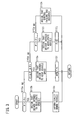
- FIG. 1 is a block diagram of a vehicle 10 incorporating therein a vehicle travel control apparatus 11 according to a first embodiment of the present invention.
- the vehicle 10 includes an accelerator pedal 12, a return spring 13 for applying a reaction force Forg (also referred to as an "original position returning force Forg") [N] as an original position returning force to the accelerator pedal 12, a depressed angle sensor 14 (accelerator pedal depressed angle sensor), a vehicle speed sensor 16 (speedometer), an automatic braking mechanism 18, a navigation system 20, an ECU (electronic control unit) 22, a reaction force applying mechanism 24, a vehicle speed control mechanism 26, and a radar device 28.
- the depressed angle sensor 14, the vehicle speed sensor 16, the radar device 28, the navigation system 20, the ECU 22, the vehicle speed control mechanism 26, and the reaction force applying mechanism 24 jointly make up the vehicle travel control apparatus 11.
- the vehicle speed sensor 16 measures a vehicle speed (present vehicle speed) V [km/h] of the vehicle 10, and outputs the measured vehicle speed V to the ECU 22.
- the automatic braking mechanism 18 includes a hydraulic pressure control mechanism 18A and a brake actuator 18B.
- the brake actuator 18B comprises disc brakes, etc., for applying braking forces to four road wheels (not shown) of the vehicle 10.
- the braking forces (braking hydraulic forces) generated by the brake actuator 18B are controlled by respective pressure regulators (not shown) in the hydraulic pressure control mechanism 18A.
- the hydraulic pressure control mechanism 18A generates a braking hydraulic pressure, which depends on the depressed angle of a brake pedal (not shown), and also generates a braking hydraulic pressure, which depends on a braking force command value output from an automatic brake controller 22C of the ECU 22 independently of the brake pedal.
- the hydraulic pressure control mechanism 18A outputs the generated braking hydraulic pressure to the brake actuator 18B.
- the navigation system 20 which is able to detect the position of the vehicle 10 in cooperation with a GPS (Global Positioning System), includes a memory 30 for storing information such as recommended speeds Vs [km/h] for certain roads.
- GPS Global Positioning System
- the recommended speed Vs refers to a speed for optimizing mileage depending on a given road situation, i.e., a so-called cruising speed, and also for limiting the speed for a road.
- the speed for optimizing mileage may be preset depending on the mileage performance of the vehicle 10, the gradient of the road, the type of road (asphalt road, gravel road, or other road), and whether or not the road has curves.
- cruising refers to a mode during which the vehicle travels continuously at a constant speed.
- traveling at a cruising speed refers to traveling at a constant speed in a most economical manner, i.e., traveling at the cruising speed.
- a recommended speed Vs can be guessed and determined, i.e., estimated, by a recommended speed estimator 22D of the ECU 22, from one or more of distance information representing the distance to a leading vehicle that can be detected by the radar device 28, information concerning operations of windshield wipers and a raindrop sensor, the history of past traffic accidents on a road, the actual driving speed on a road (which is calculated by a traffic management center from driving speeds of vehicles incorporating navigation systems on the road that have been sent to the traffic management center), a road environment (suburban area, urban area, residential area, or a school zone), the road width, the number of lanes on the road, road markings detected by image processing, and information concerning a coefficient of friction of the road.
- the recommended speed estimator 22D estimates as the recommended speed Vs a lower one of two recommended speeds Vs, i.e., a recommended speed Vs guessed and determined (estimated) depending on the position of the vehicle 10, which is detected by the navigation system 20 and sent to the recommended speed estimator 22D, or a recommended speed Vs determined based on an intervehicular distance to a leading vehicle, which is detected by the radar device 28, and a relative vehicle speed with respect to the leading vehicle.
- the ECU 22 also includes a reaction force controller 22B, which calculates a reaction force Fr applied to the accelerator pedal 12 using the recommended speed Vs and the present speed V, generates a control signal based on the calculated reaction force Fr, and applies a control signal to the reaction force applying mechanism 24 in order to enable the reaction force applying mechanism 24 to apply the reaction force Fr [N] to the accelerator pedal 12.
- a reaction force controller 22B which calculates a reaction force Fr applied to the accelerator pedal 12 using the recommended speed Vs and the present speed V, generates a control signal based on the calculated reaction force Fr, and applies a control signal to the reaction force applying mechanism 24 in order to enable the reaction force applying mechanism 24 to apply the reaction force Fr [N] to the accelerator pedal 12.
- reaction force applying mechanism 24 comprises a motor or the like, not shown, which is coupled to the accelerator pedal 12, and the reaction force applying mechanism 24 applies the reaction force Fr to the accelerator pedal 12 depending on the control signal received from the ECU 22.
- the vehicle speed control mechanism 26 includes a throttle valve, the opening of which is controlled by a so-called drive-by-wire system, and a transmission system.
- the ECU 22 operates as a function performing unit (function performing means), which performs various functions when a CPU executes programs stored in a memory 23 such as a ROM, etc., based on various input signals.
- the ECU 22 functions as an intention determiner 22A for determining the intention of the driver to adjust the vehicle speed, a reaction force controller 22B, an automatic brake controller 22C, a recommended speed estimator 22D, a target depressed angle setter (also referred to as a "target cruising speed/target depressed angle setter”) 22E, and an attention seeking depressed angle setter 22F.
- the memory 23 may comprise a flash memory, an EEPROM, a RAM, a hard disk, or the like.
- the vehicle travel control apparatus 11 is basically constructed and operates as described above.
- An operation sequence (processing sequence) of the intention determiner 22A for determining the intention of the driver to adjust the speed of the vehicle will be described in detail below with reference to the flowcharts shown in FIGS. 2 and 3 .
- step S101 while the vehicle 10 is traveling, the ECU 22 detects (acquires) the present vehicle speed V through the vehicle speed sensor 16, and detects (acquires) the present accelerator pedal depressed angle ⁇ through the depressed angle sensor 14.
- the vehicle speed V and the accelerator pedal depressed angle ⁇ are detected successively per each given time td, e.g., at each of times on the order of ms (milliseconds), while the flowchart shown in FIG. 2 is executed during traveling of the vehicle 10.
- step S102 the ECU 22, which also functions as a cruising mode determiner, judges whether or not the vehicle 10 is in a cruising mode (constant-speed traveling mode).
- the ECU 22 judges whether or not the vehicle 10 is in a constant-speed traveling mode during a certain time period by referring to the following inequalities (1) and (2).
- V - ⁇ V ⁇ V ⁇ V + ⁇ V ⁇ 1 where ⁇ V1 is a constant representing a very small speed.
- ⁇ - ⁇ ⁇ 1 ⁇ ⁇ ⁇ ⁇ + ⁇ ⁇ 1 where ⁇ 1 is a constant representing a very small accelerator pedal depressed angle.
- the ECU 22 repeats the process of step S101 and the judgment of step S102 for a certain period, e.g., 5 [sec].
- the ECU 22 decides that the vehicle 10 is in a cruising mode cruising at a constant speed when the present vehicle speed V is stable, with any deviations being maintained within a range of very small speeds of ⁇ ⁇ V1, and when the present accelerator pedal depressed angle ⁇ is stable, with any deviations being maintained in a range of very small accelerator pedal depressed angles of ⁇ 1.
- step S103 the ECU 22, which functions as the target cruising speed/target depressed angle setter 22E, sets, as a target speed (also referred to as a "target cruising speed") Vt, the present vehicle speed V of the vehicle 10 that is in the cruising mode (constant-speed traveling mode), and also sets the present accelerator pedal depressed angle ⁇ as a target accelerator pedal depressed angle (also referred to as a “target cruising accelerator pedal depressed angle”) ⁇ t.
- a target speed also referred to as a "target cruising speed”
- Vt the present vehicle speed V of the vehicle 10 that is in the cruising mode (constant-speed traveling mode)
- the present accelerator pedal depressed angle ⁇ as a target accelerator pedal depressed angle (also referred to as a "target cruising accelerator pedal depressed angle”) ⁇ t.
- step S104 the ECU 22 judges whether or not the present accelerator pedal depressed angle ⁇ exceeds the target accelerator pedal depressed angle ⁇ t. If the present accelerator pedal depressed angle ⁇ exceeds the target accelerator pedal depressed angle ⁇ t ( ⁇ > ⁇ t or ⁇ > ⁇ + ⁇ 2 where ⁇ 2 represents a margin), then in step S105, the reaction force controller 22B applies a cruising reaction force Ft to the accelerator pedal 12 through the reaction force applying mechanism 24.
- the recommended speed estimator 22D estimates a recommended speed Vs. If the navigation system 20 detects an approaching curved road in the travel direction, the navigation system 20 estimates a recommended speed Vs, which is lower than the present vehicle speed V. If the intervehicular distance to a leading vehicle is decreasing, then the radar device 28 estimates a recommended speed Vs, which is lower than the present vehicle speed V. If both of the recommended speeds Vs are estimated, then a lower one of the recommended speeds is selected as the recommended speed Vs.
- step S107 the ECU 22, which functions as an attention seeking depressed angle setter 22F, sets an attention seeking accelerator pedal depressed angle ⁇ c, which is an accelerator pedal depressed angle for driving at the estimated recommended speed Vs, according to the following equation (3).
- ⁇ c ⁇ t - ⁇ ⁇ 3
- ⁇ 3 represents the difference between the target accelerator pedal depressed angle 6t and the attention seeking accelerator pedal depressed angle ⁇ c.
- ⁇ 3 may be a constant value.
- step S108 in order to judge whether or not an attention seeking reaction force Fc should be applied, the ECU 22 judges whether or not the following inequalities (4) are satisfied.
- step S109 the ECU 22 applies an attention seeking reaction force Fc, which is considerably greater than the cruising reaction force Ft (Fc >> Ft) that was applied from step S105, for a predetermined period (attention seeking reaction force applying period), e.g., 1 [sec].
- Fc attention seeking reaction force
- the intention determining reaction force Fi is set to be smaller than the attention seeking reaction force Fc and greater than the cruising reaction force Ft.
- step S111 the ECU 22 acquires an accelerator pedal depressed angle ⁇ during the intention determining period Ti (hereinafter referred to as an "intention determining accelerator pedal depressed angle ⁇ i").
- the intention determining accelerator pedal depressed angle ⁇ i is represented by a value, which is produced by acquiring a prescribed number of accelerator pedal depressed angles ⁇ in respective given periods td during the intention determining period Ti, successively integrating maximum values of the accelerator pedal depressed angles ⁇ , and averaging the integration results with the number of the integrals, i.e., an average value representing the average of the integrals of the maximum values.
- a value (the aforementioned average value) upon elapse of the intention determining period Ti is used as the intention determining accelerator pedal depressed angle ⁇ i.
- a maximum value during the intention determining period Ti may be used as the intention determining accelerator pedal depressed angle ⁇ i.
- the intention determiner 22A determines the intention of the driver to adjust the vehicle speed based on the value of the intention determining accelerator pedal depressed angle ⁇ I, which has been acquired upon elapse of the intention determining period Ti, determines a reaction force Fr to be applied, and performs a control process for judging whether or not the vehicle 10 should be braked automatically by the automatic braking mechanism 18, i.e., performs a process for determining the driver's intention, and for controlling a reaction force and an automatic brake.
- FIG. 3 is a detailed flowchart of a process for determining the driver's intention and for controlling a reaction force and an automatic brake, which is carried out in step S112.
- steps S112a, 112d, 112g may be carried out in any desired order. Decisions to proceed to one of different alternative paths may be made not only by the if-branches shown in FIG. 3 , but also by using tables and characteristic diagrams.
- step S112a the intention determiner 22A judges whether or not the intention determining accelerator pedal depressed angle ⁇ i is smaller than the attention seeking accelerator pedal depressed angle ⁇ c. If the intention determining accelerator pedal depressed angle ⁇ i is smaller than the attention seeking accelerator pedal depressed angle ⁇ c, then in step S112b, the intention determiner 22A determines that the driver intends to decelerate the vehicle 10. In step S112c, the automatic brake controller 22C automatically brakes the vehicle 10 in order to assist the driver in decelerating the vehicle 10.
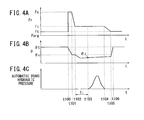
- a reaction force Fr at the origin i.e., the point of intersection between the time axis t and the reaction force Fr axis, represents the original position returning force Forg applied to the accelerator pedal 12.
- FIGS. 5A and 6A The same definition applies also to FIGS. 5A and 6A .
- step S108 the decision in step S108 is affirmative (step S108: YES), and in step S109, the attention seeking reaction force Fc begins to be applied to the accelerator pedal 12.
- the attention seeking reaction force Fc is continuously applied to the accelerator pedal 12 in step S109.
- the attention seeking reaction force Fc is sharply reduced.
- the intention determining reaction force Fi begins to be applied to the accelerator pedal 12. Basically, the intention determining reaction force Fi is applied continuously to the accelerator pedal 12 until time t103, at which point the intention determining period Ti elapses.
- the intention determiner 22A determines that the driver intends to decelerate the vehicle 10 in step S112b.
- the automatic brake controller 22C controls the automatic braking mechanism 18 so as to brake the vehicle 10 automatically between time t103 and time t104.
- the intention determining reaction force Fi is continuously applied to the accelerator pedal 12 until time t104 when automatic braking is ended, after which control returns to step S101.
- the cruising reaction force Ft is applied to the accelerator pedal 12, and the accelerator pedal depressed angle ⁇ increases again at time t105.
- the accelerator pedal depressed angle ⁇ converges to the target cruising accelerator pedal depressed angle ⁇ t.
- the recommended speed Vs is estimated as a low speed.
- the driver returns the accelerator pedal 12 according to the applied attention seeking reaction force Fc.
- the accelerator pedal depressed angle ⁇ becomes smaller than the attention seeking accelerator pedal depressed angle ⁇ c, the vehicle 10 is braked automatically in order to assist the driver in decelerating the vehicle 10.
- step S112d the intention determiner 22A judges whether or not the intention determining accelerator pedal depressed angle ⁇ i is within a range that is equal to or greater than the attention seeking accelerator pedal depressed angle ⁇ c, and equal to or smaller than the target cruising accelerator pedal depressed angle ⁇ t ( ⁇ t ⁇ ⁇ i ⁇ ⁇ c).
- step S112e the intention determiner 22A determines that the driver intends to maintain the present vehicle speed V.
- step S112f the reaction force controller 22B applies the cruising reaction force Ft to the accelerator pedal 12.
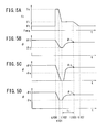
- a control process which is carried out when the driver intends to maintain the present vehicle speed V, will be described in detail below with reference to the timing charts shown in FIGS. 5A through 5D .
- the attention seeking reaction force Fc begins to be applied to the accelerator pedal 12.
- the attention seeking reaction force Fc is applied continuously to the accelerator pedal 12 during the period from time t100 to time t101.
- the attention seeking reaction force Fc is sharply reduced.
- the intention determining reaction force Fi begins to be applied to the accelerator pedal 12.
- the intention determining reaction force Fi is applied continuously to the accelerator pedal 12 until time t103, at which point the intention determining period Ti elapses.
- step S112e the intention determiner 22A determines that the driver intends or essentially intends to maintain the vehicle speed. As shown in FIG. 5A , during the period from time t103 to time t107, the intention determining reaction force Fi is restored to the cruising reaction force Ft.
- the transition (time-dependent change) of the accelerator pedal depressed angle ⁇ which is shown in FIG. 5D , indicates that the driver is imparting a load to the accelerator pedal 12 by placing the driver's foot thereon.
- the driver naturally depresses the accelerator pedal 12 as the reaction force decreases.
- steps S101 through S103 are executed in order to set the target cruising accelerator pedal depressed angle ⁇ t to the current new target cruising speed Vt (constant speed).
- step S112d the decision in step S112d is negative, then in step S112g, the intention determiner 22A judges whether or not the intention determining accelerator pedal depressed angle ⁇ i is equal to or greater than the target cruising accelerator pedal depressed angle ⁇ t. If the decision in step S112g is negative, then in step S112h, the intention determiner 22A determines that a control failure has occurred, stops the process for determining the driver's intention to adjust the vehicle speed, and indicates to the driver that a control failure has occurred through the navigation system 20 or the like.
- step S112g If the decision in step S112g is affirmative, then in step S112i, the intention determiner 22A determines that the driver intends to accelerate the vehicle 10. In step S112j, the reaction force controller 22B stops applying the reaction force Fr to the accelerator pedal 12.
- the attention seeking reaction force Fc begins to be applied to the accelerator pedal 12. During the period from time t100 to time t101, the attention seeking reaction force Fc is applied continuously to the accelerator pedal 12. During the period from time t101 to time t102, the attention seeking reaction force Fc is sharply reduced.
- the intention determining reaction force Fi begins to be applied to the accelerator pedal 12 in step S110. The intention determining reaction force Fi is applied continuously to the accelerator pedal 12 until time t103, at which point the intention determining period Ti elapses.
- step S112g YES
- the intention determiner 22A determines in step S112i that the driver intends to accelerate the vehicle.
- the transition (time-dependent change) of the accelerator pedal depressed angle ⁇ which is shown in FIG. 6C , indicates that the driver depresses the accelerator pedal 12 from time t100 while counteracting the attention seeking reaction force Fc.
- a new target cruising accelerator pedal depressed angle ⁇ t, as well as a new target cruising speed Vt also are established in steps S101 through S103.
- the vehicle travel control apparatus 11 includes the reaction force controller 22B (accelerator reaction force controller) for controlling the reaction force Fr that is applied to the accelerator pedal 12, the depressed angle sensor 14 (accelerator pedal depressed angle sensor) for detecting the accelerator pedal depressed angle ⁇ , which represents the depressed angle of the accelerator pedal 12, and the intention determiner 22A for determining the intention of the driver to adjust the vehicle speed based on the accelerator pedal depressed angle ⁇ detected by the depressed angle sensor 14.
- the reaction force controller 22B outputs the intention determining reaction force Fi, which serves as a reference, during the intention determining period Ti required in order to determine and verify the driver's intention.
- the intention determiner 22A determines the driver's intention to adjust the vehicle speed based on the accelerator pedal depressed angle ⁇ , which is detected by the depressed angle sensor 14 during the intention determining period Ti.
- the intention determining reaction force Fi is applied to the accelerator pedal 12 during the intention determining period Ti, and the intention of the driver to adjust the vehicle speed is determined from the accelerator pedal depressed angle ⁇ , which is produced by the driver during the intention determining period Ti.
- the vehicle travel control apparatus 11 also includes the recommended speed estimator 22D for estimating a recommended speed Vs for the vehicle 10 depending on the external situation around the vehicle 10 or the driving state of the vehicle 10, along with the vehicle speed sensor 16 for detecting the present vehicle speed V of the vehicle 10.
- the reaction force controller 22B judges whether or not it is necessary to seek the driver's attention based on the recommended speed Vs, which is estimated by the recommended speed estimator 22D, the present vehicle speed V, which is detected by the vehicle speed sensor 16, and the present accelerator pedal depressed angle ⁇ , which is detected by the depressed angle sensor 14. If the reaction force controller 22B determines that it is necessary to seek the attention of the driver, preferably, the attention seeking reaction force Fc is applied, and thereafter, the intention determining reaction force Fi is applied, which is smaller than the attention seeking reaction force Fc.
- the driver can be notified of an automatically determined situation in which the vehicle 10 needs to be decelerated. Since the driver's actual intention is confirmed after the driver's attention has been sought, the intention of the driver is given priority, even if the external situation or the driving state as determined by the vehicle 10 is recognized in error, or goes against the intention of the driver.
- the vehicle 10 applies the attention seeking reaction force Fc depending on the curvature of a curved road, based on information acquired from the navigation system 20 and the intervehicular distance to a leading vehicle, which is detected by the radar device 28. In other words, the vehicle 10 is decelerated based on a judgment made by the vehicle 10 itself.
- the intention determining reaction force Fi is applied, whereby the intention of the driver is determined based on the action or behavior of the driver during the time that the intention determining reaction force Fi is being applied.
- the intention of the driver to adjust the vehicle speed is given priority over the assistive action and notice from the vehicle 10.
- the vehicle travel control apparatus 11 also includes the target cruising speed/target depressed angle setter 22E for setting the target cruising accelerator pedal depressed angle ⁇ t, which is an accelerator pedal depressed angle ⁇ for maintaining the target cruising speed Vt, and which is a speed at which the driver maintains the accelerator pedal depressed angle ⁇ within a given range.
- the vehicle travel control apparatus 11 includes the attention seeking depressed angle setter 22F for setting the attention seeking accelerator pedal depressed angle ⁇ c, which is an accelerator pedal depressed angle ⁇ that serves as a threshold value, by which it is judged whether or not to seek the driver's attention.
- the reaction force controller 22B applies the cruising reaction force Ft to the accelerator pedal 12 in order to maintain the target cruising speed Vt. If the present vehicle speed V detected by the vehicle speed sensor 16 exceeds by a predetermined value the recommended speed Vs estimated by the recommended speed estimator 22D, and if the present accelerator pedal depressed angle ⁇ is greater than the attention seeking accelerator pedal depressed angle ⁇ c, then the reaction force controller 22B applies the attention seeking reaction force Fc, which is greater than the cruising reaction force Ft.
- the vehicle 10 when the vehicle 10 starts to travel in the cruising mode at the target cruising speed Vt, the vehicle 10 is capable of judging whether or not the attention of the driver should be sought. Therefore, while the driver acts frequently on the accelerator pedal 12, the vehicle 10 does not seek the driver's attention. Accordingly, an attention seeking reaction force Fc that is not intended by the driver is prevented from being applied frequently to the accelerator pedal 12.
- the intention determiner 22A determines that the driver intends to decelerate the vehicle 10 if the actual maximum value of the accelerator pedal depressed angle ⁇ during the intention determining period Ti is smaller than the attention seeking accelerator pedal depressed angle ⁇ c, which was set by the attention seeking depressed angle setter 22F.
- the driver's intention to decelerate the vehicle 10 can be determined.
- the vehicle travel control apparatus 11 also includes the automatic brake controller 22C, which brakes the vehicle 10 automatically in order to assist the driver in decelerating the vehicle 10, if the intention determiner 22A determines that the driver intends to decelerate the vehicle 10.
- the vehicle 10 when the intention determiner 22A determines that the driver intends to decelerate the vehicle 10, the vehicle 10 can be brought more quickly into a cruising mode at the target cruising speed Vt.
- the target depressed angle setter (target cruising speed/target depressed angle setter) 22E has set the target cruising speed Vt and the target cruising accelerator pedal depressed angle ⁇ t, if a situation such as a curved road or a leading vehicle, which prevents the vehicle 10 from continuing to travel at the target cruising speed Vt and maintain the target cruising accelerator pedal depressed angle ⁇ t, i.e., a situation that prevents the vehicle 10 from traveling at the target cruising speed Vt, is considered to be present at a location ahead in the direction of travel, then the set target cruising speed Vt and the set target cruising accelerator pedal depressed angle ⁇ t are stored in the memory 23 of the ECU 22.
- the speed V and the accelerator pedal depressed angle ⁇ change, respectively, from the target cruising speed Vt and the target cruising accelerator pedal depressed angle ⁇ t.
- the speed V drops and the accelerator pedal depressed angle ⁇ is reduced.
- the speed V rises and the accelerator pedal depressed angle ⁇ is increased.
- the target depressed angle setter (target cruising speed/target depressed angle setter) 22E reads the target cruising speed Vt and the target cruising accelerator pedal depressed angle ⁇ t, which are stored in the memory 23, and automatically restores (resets) the target cruising speed Vt and the target cruising accelerator pedal depressed angle ⁇ t.
- the vehicle travel control apparatus is capable of controlling driving of the vehicle 10 without causing the driver to feel uncomfortable.
Landscapes
- Engineering & Computer Science (AREA)
- Mechanical Engineering (AREA)
- Transportation (AREA)
- Automation & Control Theory (AREA)
- Chemical & Material Sciences (AREA)
- Combustion & Propulsion (AREA)
- Human Computer Interaction (AREA)
- Control Of Driving Devices And Active Controlling Of Vehicle (AREA)
- Auxiliary Drives, Propulsion Controls, And Safety Devices (AREA)
- Regulating Braking Force (AREA)
- Control Of Vehicle Engines Or Engines For Specific Uses (AREA)
- Controls For Constant Speed Travelling (AREA)
Claims (4)
- Fahrzeugfahrregelungs-/steuerungsvorrichtung, umfassend:eine Reaktionskraftregelungs-/steuerungseinheit (22B) zum Regeln/Steuern einer auf ein Gaspedal (12) anzuwendenden Reaktionskraft;einen Druckwinkelsensor (14) zum Erfassen eines Gaspedaldruckwinkels des Gaspedals (12);eine Absichtbestimmungseinheit (22A, 36A) zum Bestimmen einer Fahrzeuggeschwindigkeitanpassungsabsicht eines Fahrers basierend auf einem Gaspedaldruckwinkel, welcher durch den Druckwinkelsensor (14) erfasst wird; undeinen Fahrzeuggeschwindigkeitssensor (16) zum Erfassen einer aktuellen Fahrzeuggeschwindigkeit des Hostfahrzeugs,
dadurch gekennzeichnet, dass die Fahrzeugfahrregelungs-/steuerungsvorrichtung fernereine Richtgeschwindigkeitsberechnungseinheit (22D) zum Berechnen einer Richtgeschwindigkeit für ein Hostfahrzeug basierend auf einem externen Zustand um das Hostfahrzeug herum oder basierend auf einem Fahrzustand des Hostfahrzeugs umfasst,wobei die Reaktionskraftregelungs-/steuerungseinheit (22B) bewertet, ob es notwendig ist oder nicht, die Fahrerabsicht basierend auf der durch die Richtgeschwindigkeitsberechnungseinheit (22D) berechneten Richtgeschwindigkeit, der aktuellen, durch den Fahrzeuggeschwindigkeitssensor (16) erfassten Fahrzeuggeschwindigkeit und einem aktuellen, durch den Druckwinkelsensor (14) erfassten Gaspedaldruckwinkel zu ermitteln, und wenn die Reaktionskraftregelungs-/steuerungseinheit (22B) bestimmt, dass es notwendig ist, die Fahrerabsicht zu ermitteln, die Reaktionskraftregelungs-/steuerungseinheit (22B) eine Absichtermittlungsreaktionskraft auf das Gaspedal (12) für eine vorbestimmte Zeit anwendet, um ein Fahrzeug basierend auf einer Bewertung, welche durch das Fahrzeug selbst gemacht wird, zu bremsen und nachdem die Absichtermittlungsreaktionskraft auf eine Absichtbestimmungsreaktionskraft scharf reduziert wird, die Absichtbestimmungseinheit (22A) eine Absichtbestimmungsperiode einzustellen, welche erfordert wird, um die Fahrzeuggeschwindigkeitanpassungsabsicht des Fahrers zu bestimmen und die Reaktionskraftregelungs-/steuerungseinheit (22B) eine Absichtbestimmungsreaktionskraft anwendet, welche während einer Absichtbestimmungsperiode als eine Referenz dient und kleiner ist als die Absichtermittlungsreaktionskraft für die Absichtbestimmungsperiode, unddie Absichtbestimmungseinheit (22A) die Fahrzeuggeschwindigkeitanpassungsabsicht des Fahrers abhängig von dem Gaspedaldruckwinkel besimmt, welcher durch den Druckwinkelsensor (14) während der Absichtbestimmungsperiode erfasst wird. - Fahrzeugfahrregelungs-/steuerungsvorrichtung nach Anspruch 1, ferner umfassend:eine Soll-Druckwinkeleinstellungseinheit (22E) zum Einstellen eines Soll-Gaspedaldruckwinkels, welcher der Gaspedaldruckwinkel ist, welcher erfordert wird, um die Soll-Fahrgeschwindigkeit einzuhalten, welche eine Fahrzeuggeschwindigkeit ist, wenn der Fahrer den Gaspedaldruckwinkel innerhalb eines vorbestimmten Bereiches aufrechterhält; undeine Absichtermittlungsdruckwinkeleinstellungseinheit (22F) zum Einstellen eines Absichtermittlungsgaspedaldruckwinkels, welcher der Gaspedaldruckwinkel ist, welcher
auf einen Wert, welcher kleiner als der Soll-Gaspedaldruckwinkel ist, eingestellt wird, als ein Schwellenwert zum Bewerten, ob die Fahrerabsicht zu ermitteln ist oder nicht;wobei, wenn ein durch den Druckwinkelsensor (14) erfasster Ist-Gaspedaldruckwinkel größer ist als der durch die Soll-Druckwinkeleinstellungseinheit (22E) eingestellte Soll-Gaspedaldruckwinkel, die Reaktionskraftregelungs-/steuerungseinheit (22B) eine Fahrreaktionskraft, welche kleiner ist als die Absichtbestimmungsreaktionskraft, auf ein Gaspedal (12) anwendet, zum Aufrechterhalten der Soll-Fahrgeschwindigkeit, und, wenn die durch den Fahrzeuggeschwindigkeitssensor (16) erfasste, aktuelle Fahrgeschwindigkeit um wenigstens einem vorbestimmten Wert größer ist als die durch die Richtgeschwindigkeitsberechnungseinheit (22D) berechnete Richtgeschwindigkeit, und der aktuelle Gaspedaldruckwinkel größer ist als der Absichtermittlungsgaspedaldruckwinkel, die Reaktionskraftregelungs-/steuerungseinheit (22B) die Absichtermittlungsreaktionskraft anwendet, welche größer ist als die Absichtbestimmungsreaktionskraft. - Fahrzeugfahrregelungs-/steuerungsvorrichtung nach Anspruch 2, wobei, wenn ein Maximalwert des Ist-Gaspedaldruckwinkels in der Absichtbestimmungsperiode kleiner ist als der durch die Absichtermittlungsdruckwinkeleinstellungseinheit (22F) eingestellte Absichtermittlungsgaspedaldruckwinkel, die Absichtbestimmungseinheit (22A) bestimmt, dass der Fahrer beabsichtigt, das Hostfahrzeug zu bremsen.
- Fahrzeugfahrregelungs-/steuerungsvorrichtung nach Anspruch 3, ferner umfassend:eine automatische Bremsregelungs-/steuerungseinheit (22C);wobei, wenn die Absichtbestimmungseinheit (22A) bestimmt, dass der Fahrer beabsichtigt, das Hostfahrzeug zu bremsen, die automatische Bremsregelungs-/steuerungseinheit (22C) das Hostfahrzeug automatisch bremst, um dem Fahrer beim Bremsen des Hostfahrzeugs zu assistieren.
Applications Claiming Priority (3)
| Application Number | Priority Date | Filing Date | Title |
|---|---|---|---|
| JP2010211226 | 2010-09-21 | ||
| JP2010231376 | 2010-10-14 | ||
| PCT/JP2011/068461 WO2012039212A1 (ja) | 2010-09-21 | 2011-08-12 | 車両用走行制御装置 |
Publications (3)
| Publication Number | Publication Date |
|---|---|
| EP2620344A1 EP2620344A1 (de) | 2013-07-31 |
| EP2620344A4 EP2620344A4 (de) | 2014-10-08 |
| EP2620344B1 true EP2620344B1 (de) | 2015-12-16 |
Family
ID=45873706
Family Applications (1)
| Application Number | Title | Priority Date | Filing Date |
|---|---|---|---|
| EP11826658.4A Not-in-force EP2620344B1 (de) | 2010-09-21 | 2011-08-12 | Steuervorrichtung für fahrzeugreise |
Country Status (5)
| Country | Link |
|---|---|
| US (1) | US9061630B2 (de) |
| EP (1) | EP2620344B1 (de) |
| JP (1) | JP5689471B2 (de) |
| CN (1) | CN103209876B (de) |
| WO (1) | WO2012039212A1 (de) |
Families Citing this family (54)
| Publication number | Priority date | Publication date | Assignee | Title |
|---|---|---|---|---|
| EP2620344B1 (de) * | 2010-09-21 | 2015-12-16 | Honda Motor Co., Ltd. | Steuervorrichtung für fahrzeugreise |
| JP5916444B2 (ja) * | 2012-03-08 | 2016-05-11 | 日立建機株式会社 | 鉱山用車両 |
| JP5927717B2 (ja) * | 2012-03-30 | 2016-06-01 | 本田技研工業株式会社 | 走行制御装置 |
| JP5927720B2 (ja) * | 2012-06-22 | 2016-06-01 | 本田技研工業株式会社 | ペダル反力付与装置 |
| US8831809B2 (en) * | 2012-07-03 | 2014-09-09 | Ford Global Technologies, Llc | Method and system to avoid unintended engine on/offs for hybrid vehicles |
| DE112012007124T5 (de) * | 2012-11-13 | 2015-07-23 | Toyota Jidosha Kabushiki Kaisha | Fahrassistenzvorrichtung und Fahrassistenzverfahren |
| JP5733293B2 (ja) * | 2012-11-28 | 2015-06-10 | トヨタ自動車株式会社 | 走行制御装置 |
| JP5904157B2 (ja) * | 2013-05-21 | 2016-04-13 | トヨタ自動車株式会社 | 制御装置 |
| JP6167664B2 (ja) * | 2013-05-22 | 2017-07-26 | 三菱自動車工業株式会社 | 運転支援装置 |
| JP6167665B2 (ja) * | 2013-05-22 | 2017-07-26 | 三菱自動車工業株式会社 | 運転支援装置 |
| CN105247192B (zh) * | 2013-05-31 | 2018-11-16 | 日立汽车系统株式会社 | 车辆控制装置以及车辆控制方法 |
| JP6172451B2 (ja) * | 2013-08-12 | 2017-08-02 | マツダ株式会社 | 車両用制動装置 |
| WO2015025736A1 (ja) * | 2013-08-22 | 2015-02-26 | 本田技研工業株式会社 | アクセルペダル反力制御装置 |
| US8930124B1 (en) * | 2013-08-30 | 2015-01-06 | International Business Machines Corporation | Dynamic speed limit generation |
| AT514754B1 (de) * | 2013-09-05 | 2018-06-15 | Avl List Gmbh | Verfahren und Vorrichtung zur Optimierung von Fahrassistenzsystemen |
| CN106662021B (zh) * | 2014-09-19 | 2019-12-03 | 日立汽车系统株式会社 | 车辆控制装置和车辆控制方法 |
| KR101550638B1 (ko) * | 2014-09-22 | 2015-09-07 | 현대자동차 주식회사 | 차량 구동 제어 방법 및 시스템 |
| JP6396742B2 (ja) * | 2014-09-30 | 2018-09-26 | 本田技研工業株式会社 | 車両用運転操作誘導制御システム |
| JP2016084049A (ja) * | 2014-10-27 | 2016-05-19 | トヨタ自動車株式会社 | 車両走行制御装置 |
| JP6181678B2 (ja) * | 2015-01-29 | 2017-08-16 | トヨタ自動車株式会社 | 車両制動制御装置 |
| JP2016168985A (ja) * | 2015-03-16 | 2016-09-23 | トヨタ自動車株式会社 | 走行制御装置 |
| US9550495B2 (en) * | 2015-03-27 | 2017-01-24 | Intel Corporation | Technologies for assisting vehicles with changing road conditions |
| EP3109119B1 (de) * | 2015-06-23 | 2022-08-10 | Volvo Car Corporation | Verfahren und anordnung zur ermöglichung von sekundären aufgaben beim halbautomatischen fahren |
| KR101704221B1 (ko) * | 2015-06-24 | 2017-02-07 | 현대자동차주식회사 | 차량 주행 제어 방법 |
| CN105015544A (zh) * | 2015-07-27 | 2015-11-04 | 江苏大学 | 一种电动汽车全自动泊车过程中的车速控制系统及方法 |
| EP3151216A1 (de) * | 2015-10-01 | 2017-04-05 | Volvo Car Corporation | Verfahren um einen fahrer zu warnen und warnsystem |
| JP6613825B2 (ja) * | 2015-11-05 | 2019-12-04 | トヨタ自動車株式会社 | 車両制御装置 |
| JP6514634B2 (ja) * | 2015-12-25 | 2019-05-15 | 株式会社デンソー | 車両制御装置及び車両制御方法 |
| JP6878785B2 (ja) * | 2016-07-29 | 2021-06-02 | 日産自動車株式会社 | 制動制御方法及び制動制御装置 |
| JP6520877B2 (ja) * | 2016-09-20 | 2019-05-29 | トヨタ自動車株式会社 | 車両走行制御装置 |
| JP6646617B2 (ja) * | 2017-05-22 | 2020-02-14 | 本田技研工業株式会社 | 自動走行制御装置 |
| JP6972744B2 (ja) * | 2017-08-01 | 2021-11-24 | トヨタ自動車株式会社 | 運転支援装置 |
| JP6568559B2 (ja) * | 2017-09-13 | 2019-08-28 | 株式会社Subaru | 車両の走行制御装置 |
| FR3071219B1 (fr) * | 2017-09-15 | 2019-10-18 | Jtekt Europe | Procede d’optimisation d’un parametre indicateur de vitesse vehicule destine aux fonctions d’assistance de direction et aux fonctions de securisation |
| JP6796576B2 (ja) * | 2017-12-27 | 2020-12-09 | 本田技研工業株式会社 | 自動運転車両の走行制御装置 |
| JP6648384B2 (ja) * | 2018-02-26 | 2020-02-14 | 本田技研工業株式会社 | 車両制御装置、車両制御方法、およびプログラム |
| CN108357493A (zh) * | 2018-02-27 | 2018-08-03 | 牟特科技(北京)有限公司 | 一种车辆智能巡航的方法及装置 |
| JP6745851B2 (ja) * | 2018-09-18 | 2020-08-26 | 本田技研工業株式会社 | 車両の制御装置 |
| CN109250656A (zh) * | 2018-10-11 | 2019-01-22 | 广东白云学院 | 叉车的防碰撞系统、控制方法及叉车 |
| JP7143733B2 (ja) * | 2018-11-14 | 2022-09-29 | トヨタ自動車株式会社 | 環境状態推定装置、環境状態推定方法、環境状態推定プログラム |
| JP7168910B2 (ja) * | 2019-01-29 | 2022-11-10 | トヨタ自動車株式会社 | 車両走行制御装置 |
| JP2020138600A (ja) * | 2019-02-27 | 2020-09-03 | 本田技研工業株式会社 | 車両制御システム |
| JP2020169580A (ja) * | 2019-04-01 | 2020-10-15 | トヨタ自動車株式会社 | 車両の駆動力制御装置 |
| JP7140077B2 (ja) * | 2019-09-02 | 2022-09-21 | トヨタ自動車株式会社 | 衝突回避支援装置 |
| JP7215383B2 (ja) * | 2019-09-20 | 2023-01-31 | トヨタ自動車株式会社 | 車両用ペダル装置 |
| US11285949B2 (en) * | 2019-12-04 | 2022-03-29 | Hyundai Motor Company | Vehicle travel control system and control method therefor |
| US11352004B2 (en) | 2019-12-04 | 2022-06-07 | Hyundai Motor Company | Vehicle travel control system and control method therefor |
| CN113022564A (zh) * | 2019-12-25 | 2021-06-25 | 北京宝沃汽车股份有限公司 | 车速控制方法,装置,存储介质及电子设备 |
| AT523641B1 (de) | 2020-06-16 | 2021-10-15 | Avl List Gmbh | System zum Testen eines Fahrerassistenzsystems eines Fahrzeugs |
| AT524822B1 (de) | 2021-03-01 | 2024-08-15 | Avl List Gmbh | Verfahren zum Testen eines Fahrerassistenzsystems eines Fahrzeugs |
| CN113044021B (zh) * | 2021-04-28 | 2022-08-30 | 东风汽车集团股份有限公司 | 一种基于道路场景和驾驶意图的节油系统和控制方法 |
| JP7701826B2 (ja) * | 2021-07-30 | 2025-07-02 | 株式会社Subaru | 制動制御装置 |
| CN114103635A (zh) * | 2021-12-08 | 2022-03-01 | 安徽江淮汽车集团股份有限公司 | 车辆防误踩油门方法及系统 |
| CN116495002B (zh) * | 2023-04-27 | 2024-04-16 | 中国第一汽车股份有限公司 | 车辆行驶控制方法、装置、电子设备、存储介质及车辆 |
Family Cites Families (24)
| Publication number | Priority date | Publication date | Assignee | Title |
|---|---|---|---|---|
| JP3133770B2 (ja) | 1991-01-18 | 2001-02-13 | マツダ株式会社 | 自動車の走行システム |
| JP3451665B2 (ja) * | 1993-09-02 | 2003-09-29 | マツダ株式会社 | パワートレインの制御装置 |
| US6792344B2 (en) * | 1997-04-25 | 2004-09-14 | Hitachi, Ltd. | Automotive control apparatus and method |
| JP3671134B2 (ja) * | 2000-04-05 | 2005-07-13 | 株式会社豊田中央研究所 | タイヤパラメータ推定装置 |
| JP3785959B2 (ja) | 2001-07-19 | 2006-06-14 | 日産自動車株式会社 | 車両用走行制御装置 |
| JP2003237421A (ja) * | 2002-02-18 | 2003-08-27 | Nissan Motor Co Ltd | 車両の駆動力制御装置 |
| JP3573134B2 (ja) * | 2002-02-25 | 2004-10-06 | 日産自動車株式会社 | 車両用運転操作補助装置 |
| JP4186675B2 (ja) * | 2003-03-28 | 2008-11-26 | 日産自動車株式会社 | 車両走行制御装置 |
| JP4104532B2 (ja) * | 2003-11-10 | 2008-06-18 | 本田技研工業株式会社 | 車両制御装置 |
| JP4254501B2 (ja) * | 2003-11-20 | 2009-04-15 | 日産自動車株式会社 | 車両用運転操作補助装置および車両用運転操作補助装置を備えた車両 |
| JP4501592B2 (ja) * | 2004-08-24 | 2010-07-14 | トヨタ自動車株式会社 | 無段変速機を搭載した車両の制御装置 |
| JP2007022238A (ja) | 2005-07-14 | 2007-02-01 | Nissan Motor Co Ltd | 車両用運転操作補助装置および車両用運転操作補助装置を備えた車両 |
| JP4595725B2 (ja) * | 2005-07-20 | 2010-12-08 | トヨタ自動車株式会社 | 走行支援装置 |
| JP4765766B2 (ja) * | 2006-05-23 | 2011-09-07 | 日産自動車株式会社 | 車両用運転操作補助装置および車両用運転操作補助装置を備えた車両 |
| JP2008081006A (ja) * | 2006-09-28 | 2008-04-10 | Mitsubishi Electric Corp | 車両用走行制御装置 |
| JP5280092B2 (ja) * | 2008-04-28 | 2013-09-04 | 本田技研工業株式会社 | 車両用走行制御装置及び運転者意図検出方法 |
| JP5193290B2 (ja) | 2008-05-09 | 2013-05-08 | 本田技研工業株式会社 | 車両走行制御装置 |
| JP5130152B2 (ja) * | 2008-08-26 | 2013-01-30 | 本田技研工業株式会社 | 自動走行解除装置 |
| JP5137764B2 (ja) * | 2008-09-29 | 2013-02-06 | 株式会社アドヴィックス | 車両の速度制御装置 |
| JP2010076697A (ja) * | 2008-09-29 | 2010-04-08 | Advics Co Ltd | 車両の速度制御装置 |
| JP5556523B2 (ja) * | 2010-09-13 | 2014-07-23 | トヨタ自動車株式会社 | 車両の制御装置 |
| EP2620344B1 (de) * | 2010-09-21 | 2015-12-16 | Honda Motor Co., Ltd. | Steuervorrichtung für fahrzeugreise |
| DE102010041539A1 (de) * | 2010-09-28 | 2012-03-29 | Bayerische Motoren Werke Aktiengesellschaft | Fahrerassistenzsystem zur Unterstützung des Fahrers zum verbrauchskontrollierten Fahren |
| DE102010041544B4 (de) * | 2010-09-28 | 2023-05-04 | Bayerische Motoren Werke Aktiengesellschaft | Fahrerassistenzsystem zur Unterstützung des Fahrers zum verbrauchskontrollierten Fahren |
-
2011
- 2011-08-12 EP EP11826658.4A patent/EP2620344B1/de not_active Not-in-force
- 2011-08-12 US US13/823,795 patent/US9061630B2/en active Active
- 2011-08-12 JP JP2012534965A patent/JP5689471B2/ja not_active Expired - Fee Related
- 2011-08-12 CN CN201180044514.1A patent/CN103209876B/zh not_active Expired - Fee Related
- 2011-08-12 WO PCT/JP2011/068461 patent/WO2012039212A1/ja not_active Ceased
Also Published As
| Publication number | Publication date |
|---|---|
| CN103209876A (zh) | 2013-07-17 |
| EP2620344A4 (de) | 2014-10-08 |
| US20130173113A1 (en) | 2013-07-04 |
| JPWO2012039212A1 (ja) | 2014-02-03 |
| US9061630B2 (en) | 2015-06-23 |
| JP5689471B2 (ja) | 2015-03-25 |
| CN103209876B (zh) | 2016-01-06 |
| EP2620344A1 (de) | 2013-07-31 |
| WO2012039212A1 (ja) | 2012-03-29 |
Similar Documents
| Publication | Publication Date | Title |
|---|---|---|
| EP2620344B1 (de) | Steuervorrichtung für fahrzeugreise | |
| US11370430B2 (en) | Driving control apparatus for vehicle | |
| US11186278B2 (en) | Driving control apparatus for vehicle | |
| US11396294B2 (en) | Driving control apparatus for vehicle | |
| US11691651B2 (en) | Vehicle control apparatus and method | |
| EP1769962B1 (de) | Adaptives Geschwindigkeitsregelsystem für Kraftfahrzeug | |
| US7206686B2 (en) | System and method for detecting an object ahead of a vehicle and controlling the vehicle in response to the detected object | |
| EP3707046B1 (de) | Einstellen der längsbewegungssteuerung eines host-kraftfahrzeugs basierend auf der schätzung der fahrtrajektorie eines führenden kraftfahrzeugs | |
| JP7205761B2 (ja) | 車両の走行制御装置 | |
| JP5706698B2 (ja) | 自動車用自動減速装置 | |
| EP1065087A2 (de) | Fahrgeschwindigkeitsregelsystem zur optimierten Abstandsregelung | |
| US20090164083A1 (en) | Method for Speed Regulation of a Motor Vehicle in a Complex Traffic Situation | |
| JP2019215730A (ja) | 車両の運転支援装置 | |
| US20200171943A1 (en) | Reaction force control system for accelerator pedal | |
| US8897962B2 (en) | Reaction force control device | |
| JP4946212B2 (ja) | 走行支援装置 | |
| JP2021109558A (ja) | 車両走行制御装置 | |
| JP2008012951A (ja) | 車両用減速意志判定装置および走行制御装置 | |
| US20200139968A1 (en) | Vehicle control device | |
| Lee | Automatic speed control system for vehicle approaching and driving on a curve | |
| US12103524B1 (en) | Driving control method and driving control device | |
| JP2023537150A (ja) | 車両の縦方向速度の自動化された管理のための方法 | |
| JP5018411B2 (ja) | 車両用追従装置 | |
| JP2021008153A (ja) | 車両走行制御装置 | |
| WO2025134369A1 (ja) | 運転制御方法及び運転制御装置 |
Legal Events
| Date | Code | Title | Description |
|---|---|---|---|
| PUAI | Public reference made under article 153(3) epc to a published international application that has entered the european phase |
Free format text: ORIGINAL CODE: 0009012 |
|
| 17P | Request for examination filed |
Effective date: 20130319 |
|
| AK | Designated contracting states |
Kind code of ref document: A1 Designated state(s): AL AT BE BG CH CY CZ DE DK EE ES FI FR GB GR HR HU IE IS IT LI LT LU LV MC MK MT NL NO PL PT RO RS SE SI SK SM TR |
|
| DAX | Request for extension of the european patent (deleted) | ||
| A4 | Supplementary search report drawn up and despatched |
Effective date: 20140910 |
|
| RIC1 | Information provided on ipc code assigned before grant |
Ipc: B60W 10/184 20120101ALI20140904BHEP Ipc: B60W 50/16 20120101ALI20140904BHEP Ipc: B60T 7/22 20060101ALI20140904BHEP Ipc: B60K 26/02 20060101ALI20140904BHEP Ipc: B60W 30/18 20120101AFI20140904BHEP Ipc: B60W 50/10 20120101ALI20140904BHEP Ipc: B60W 10/06 20060101ALI20140904BHEP |
|
| REG | Reference to a national code |
Ref country code: DE Ref legal event code: R079 Ref document number: 602011022139 Country of ref document: DE Free format text: PREVIOUS MAIN CLASS: B60W0050080000 Ipc: B60W0030140000 |
|
| GRAP | Despatch of communication of intention to grant a patent |
Free format text: ORIGINAL CODE: EPIDOSNIGR1 |
|
| RIC1 | Information provided on ipc code assigned before grant |
Ipc: B60W 30/18 20120101ALI20150605BHEP Ipc: B60W 10/184 20120101ALI20150605BHEP Ipc: B60W 50/14 20120101ALI20150605BHEP Ipc: B60W 10/06 20060101ALI20150605BHEP Ipc: B60K 26/02 20060101ALI20150605BHEP Ipc: B60W 30/14 20060101AFI20150605BHEP Ipc: B60W 50/10 20120101ALI20150605BHEP Ipc: B60W 50/08 20120101ALI20150605BHEP Ipc: B60W 50/16 20120101ALI20150605BHEP |
|
| INTG | Intention to grant announced |
Effective date: 20150714 |
|
| GRAS | Grant fee paid |
Free format text: ORIGINAL CODE: EPIDOSNIGR3 |
|
| GRAA | (expected) grant |
Free format text: ORIGINAL CODE: 0009210 |
|
| AK | Designated contracting states |
Kind code of ref document: B1 Designated state(s): AL AT BE BG CH CY CZ DE DK EE ES FI FR GB GR HR HU IE IS IT LI LT LU LV MC MK MT NL NO PL PT RO RS SE SI SK SM TR |
|
| REG | Reference to a national code |
Ref country code: GB Ref legal event code: FG4D |
|
| REG | Reference to a national code |
Ref country code: CH Ref legal event code: EP |
|
| REG | Reference to a national code |
Ref country code: IE Ref legal event code: FG4D |
|
| REG | Reference to a national code |
Ref country code: AT Ref legal event code: REF Ref document number: 765418 Country of ref document: AT Kind code of ref document: T Effective date: 20160115 |
|
| REG | Reference to a national code |
Ref country code: DE Ref legal event code: R096 Ref document number: 602011022139 Country of ref document: DE |
|
| REG | Reference to a national code |
Ref country code: NL Ref legal event code: MP Effective date: 20151216 |
|
| REG | Reference to a national code |
Ref country code: LT Ref legal event code: MG4D |
|
| PG25 | Lapsed in a contracting state [announced via postgrant information from national office to epo] |
Ref country code: NO Free format text: LAPSE BECAUSE OF FAILURE TO SUBMIT A TRANSLATION OF THE DESCRIPTION OR TO PAY THE FEE WITHIN THE PRESCRIBED TIME-LIMIT Effective date: 20160316 Ref country code: HR Free format text: LAPSE BECAUSE OF FAILURE TO SUBMIT A TRANSLATION OF THE DESCRIPTION OR TO PAY THE FEE WITHIN THE PRESCRIBED TIME-LIMIT Effective date: 20151216 Ref country code: LT Free format text: LAPSE BECAUSE OF FAILURE TO SUBMIT A TRANSLATION OF THE DESCRIPTION OR TO PAY THE FEE WITHIN THE PRESCRIBED TIME-LIMIT Effective date: 20151216 |
|
| REG | Reference to a national code |
Ref country code: AT Ref legal event code: MK05 Ref document number: 765418 Country of ref document: AT Kind code of ref document: T Effective date: 20151216 |
|
| PG25 | Lapsed in a contracting state [announced via postgrant information from national office to epo] |
Ref country code: FI Free format text: LAPSE BECAUSE OF FAILURE TO SUBMIT A TRANSLATION OF THE DESCRIPTION OR TO PAY THE FEE WITHIN THE PRESCRIBED TIME-LIMIT Effective date: 20151216 Ref country code: RS Free format text: LAPSE BECAUSE OF FAILURE TO SUBMIT A TRANSLATION OF THE DESCRIPTION OR TO PAY THE FEE WITHIN THE PRESCRIBED TIME-LIMIT Effective date: 20151216 Ref country code: LV Free format text: LAPSE BECAUSE OF FAILURE TO SUBMIT A TRANSLATION OF THE DESCRIPTION OR TO PAY THE FEE WITHIN THE PRESCRIBED TIME-LIMIT Effective date: 20151216 Ref country code: NL Free format text: LAPSE BECAUSE OF FAILURE TO SUBMIT A TRANSLATION OF THE DESCRIPTION OR TO PAY THE FEE WITHIN THE PRESCRIBED TIME-LIMIT Effective date: 20151216 Ref country code: GR Free format text: LAPSE BECAUSE OF FAILURE TO SUBMIT A TRANSLATION OF THE DESCRIPTION OR TO PAY THE FEE WITHIN THE PRESCRIBED TIME-LIMIT Effective date: 20160317 Ref country code: SE Free format text: LAPSE BECAUSE OF FAILURE TO SUBMIT A TRANSLATION OF THE DESCRIPTION OR TO PAY THE FEE WITHIN THE PRESCRIBED TIME-LIMIT Effective date: 20151216 |
|
| PG25 | Lapsed in a contracting state [announced via postgrant information from national office to epo] |
Ref country code: IT Free format text: LAPSE BECAUSE OF FAILURE TO SUBMIT A TRANSLATION OF THE DESCRIPTION OR TO PAY THE FEE WITHIN THE PRESCRIBED TIME-LIMIT Effective date: 20151216 Ref country code: CZ Free format text: LAPSE BECAUSE OF FAILURE TO SUBMIT A TRANSLATION OF THE DESCRIPTION OR TO PAY THE FEE WITHIN THE PRESCRIBED TIME-LIMIT Effective date: 20151216 Ref country code: ES Free format text: LAPSE BECAUSE OF FAILURE TO SUBMIT A TRANSLATION OF THE DESCRIPTION OR TO PAY THE FEE WITHIN THE PRESCRIBED TIME-LIMIT Effective date: 20151216 |
|
| PG25 | Lapsed in a contracting state [announced via postgrant information from national office to epo] |
Ref country code: AT Free format text: LAPSE BECAUSE OF FAILURE TO SUBMIT A TRANSLATION OF THE DESCRIPTION OR TO PAY THE FEE WITHIN THE PRESCRIBED TIME-LIMIT Effective date: 20151216 Ref country code: SK Free format text: LAPSE BECAUSE OF FAILURE TO SUBMIT A TRANSLATION OF THE DESCRIPTION OR TO PAY THE FEE WITHIN THE PRESCRIBED TIME-LIMIT Effective date: 20151216 Ref country code: SM Free format text: LAPSE BECAUSE OF FAILURE TO SUBMIT A TRANSLATION OF THE DESCRIPTION OR TO PAY THE FEE WITHIN THE PRESCRIBED TIME-LIMIT Effective date: 20151216 Ref country code: EE Free format text: LAPSE BECAUSE OF FAILURE TO SUBMIT A TRANSLATION OF THE DESCRIPTION OR TO PAY THE FEE WITHIN THE PRESCRIBED TIME-LIMIT Effective date: 20151216 Ref country code: IS Free format text: LAPSE BECAUSE OF FAILURE TO SUBMIT A TRANSLATION OF THE DESCRIPTION OR TO PAY THE FEE WITHIN THE PRESCRIBED TIME-LIMIT Effective date: 20160416 Ref country code: RO Free format text: LAPSE BECAUSE OF FAILURE TO SUBMIT A TRANSLATION OF THE DESCRIPTION OR TO PAY THE FEE WITHIN THE PRESCRIBED TIME-LIMIT Effective date: 20151216 Ref country code: PT Free format text: LAPSE BECAUSE OF FAILURE TO SUBMIT A TRANSLATION OF THE DESCRIPTION OR TO PAY THE FEE WITHIN THE PRESCRIBED TIME-LIMIT Effective date: 20160418 |
|
| REG | Reference to a national code |
Ref country code: DE Ref legal event code: R097 Ref document number: 602011022139 Country of ref document: DE |
|
| PLBE | No opposition filed within time limit |
Free format text: ORIGINAL CODE: 0009261 |
|
| STAA | Information on the status of an ep patent application or granted ep patent |
Free format text: STATUS: NO OPPOSITION FILED WITHIN TIME LIMIT |
|
| PG25 | Lapsed in a contracting state [announced via postgrant information from national office to epo] |
Ref country code: DK Free format text: LAPSE BECAUSE OF FAILURE TO SUBMIT A TRANSLATION OF THE DESCRIPTION OR TO PAY THE FEE WITHIN THE PRESCRIBED TIME-LIMIT Effective date: 20151216 Ref country code: PL Free format text: LAPSE BECAUSE OF FAILURE TO SUBMIT A TRANSLATION OF THE DESCRIPTION OR TO PAY THE FEE WITHIN THE PRESCRIBED TIME-LIMIT Effective date: 20151216 |
|
| 26N | No opposition filed |
Effective date: 20160919 |
|
| PG25 | Lapsed in a contracting state [announced via postgrant information from national office to epo] |
Ref country code: BE Free format text: LAPSE BECAUSE OF FAILURE TO SUBMIT A TRANSLATION OF THE DESCRIPTION OR TO PAY THE FEE WITHIN THE PRESCRIBED TIME-LIMIT Effective date: 20151216 |
|
| PG25 | Lapsed in a contracting state [announced via postgrant information from national office to epo] |
Ref country code: SI Free format text: LAPSE BECAUSE OF FAILURE TO SUBMIT A TRANSLATION OF THE DESCRIPTION OR TO PAY THE FEE WITHIN THE PRESCRIBED TIME-LIMIT Effective date: 20151216 |
|
| REG | Reference to a national code |
Ref country code: DE Ref legal event code: R119 Ref document number: 602011022139 Country of ref document: DE |
|
| PG25 | Lapsed in a contracting state [announced via postgrant information from national office to epo] |
Ref country code: MC Free format text: LAPSE BECAUSE OF FAILURE TO SUBMIT A TRANSLATION OF THE DESCRIPTION OR TO PAY THE FEE WITHIN THE PRESCRIBED TIME-LIMIT Effective date: 20151216 |
|
| REG | Reference to a national code |
Ref country code: CH Ref legal event code: PL |
|
| GBPC | Gb: european patent ceased through non-payment of renewal fee |
Effective date: 20160812 |
|
| PG25 | Lapsed in a contracting state [announced via postgrant information from national office to epo] |
Ref country code: CH Free format text: LAPSE BECAUSE OF NON-PAYMENT OF DUE FEES Effective date: 20160831 Ref country code: LI Free format text: LAPSE BECAUSE OF NON-PAYMENT OF DUE FEES Effective date: 20160831 |
|
| REG | Reference to a national code |
Ref country code: FR Ref legal event code: ST Effective date: 20170428 |
|
| REG | Reference to a national code |
Ref country code: IE Ref legal event code: MM4A |
|
| PG25 | Lapsed in a contracting state [announced via postgrant information from national office to epo] |
Ref country code: FR Free format text: LAPSE BECAUSE OF NON-PAYMENT OF DUE FEES Effective date: 20160831 Ref country code: DE Free format text: LAPSE BECAUSE OF NON-PAYMENT OF DUE FEES Effective date: 20170301 Ref country code: IE Free format text: LAPSE BECAUSE OF NON-PAYMENT OF DUE FEES Effective date: 20160812 Ref country code: GB Free format text: LAPSE BECAUSE OF NON-PAYMENT OF DUE FEES Effective date: 20160812 |
|
| PG25 | Lapsed in a contracting state [announced via postgrant information from national office to epo] |
Ref country code: LU Free format text: LAPSE BECAUSE OF NON-PAYMENT OF DUE FEES Effective date: 20160812 |
|
| PG25 | Lapsed in a contracting state [announced via postgrant information from national office to epo] |
Ref country code: HU Free format text: LAPSE BECAUSE OF FAILURE TO SUBMIT A TRANSLATION OF THE DESCRIPTION OR TO PAY THE FEE WITHIN THE PRESCRIBED TIME-LIMIT; INVALID AB INITIO Effective date: 20110812 Ref country code: CY Free format text: LAPSE BECAUSE OF FAILURE TO SUBMIT A TRANSLATION OF THE DESCRIPTION OR TO PAY THE FEE WITHIN THE PRESCRIBED TIME-LIMIT Effective date: 20151216 |
|
| PG25 | Lapsed in a contracting state [announced via postgrant information from national office to epo] |
Ref country code: MK Free format text: LAPSE BECAUSE OF FAILURE TO SUBMIT A TRANSLATION OF THE DESCRIPTION OR TO PAY THE FEE WITHIN THE PRESCRIBED TIME-LIMIT Effective date: 20151216 Ref country code: TR Free format text: LAPSE BECAUSE OF FAILURE TO SUBMIT A TRANSLATION OF THE DESCRIPTION OR TO PAY THE FEE WITHIN THE PRESCRIBED TIME-LIMIT Effective date: 20151216 Ref country code: MT Free format text: LAPSE BECAUSE OF NON-PAYMENT OF DUE FEES Effective date: 20160831 |
|
| PG25 | Lapsed in a contracting state [announced via postgrant information from national office to epo] |
Ref country code: BG Free format text: LAPSE BECAUSE OF FAILURE TO SUBMIT A TRANSLATION OF THE DESCRIPTION OR TO PAY THE FEE WITHIN THE PRESCRIBED TIME-LIMIT Effective date: 20151216 |
|
| PG25 | Lapsed in a contracting state [announced via postgrant information from national office to epo] |
Ref country code: AL Free format text: LAPSE BECAUSE OF FAILURE TO SUBMIT A TRANSLATION OF THE DESCRIPTION OR TO PAY THE FEE WITHIN THE PRESCRIBED TIME-LIMIT Effective date: 20151216 |