EP2531789B1 - Kühlschrank und steuerungsverfahren dafür - Google Patents
Kühlschrank und steuerungsverfahren dafür Download PDFInfo
- Publication number
- EP2531789B1 EP2531789B1 EP11737253.2A EP11737253A EP2531789B1 EP 2531789 B1 EP2531789 B1 EP 2531789B1 EP 11737253 A EP11737253 A EP 11737253A EP 2531789 B1 EP2531789 B1 EP 2531789B1
- Authority
- EP
- European Patent Office
- Prior art keywords
- door
- light emitting
- sub
- refrigerator
- light
- Prior art date
- Legal status (The legal status is an assumption and is not a legal conclusion. Google has not performed a legal analysis and makes no representation as to the accuracy of the status listed.)
- Active
Links
Images


Classifications
-
- A—HUMAN NECESSITIES
- A47—FURNITURE; DOMESTIC ARTICLES OR APPLIANCES; COFFEE MILLS; SPICE MILLS; SUCTION CLEANERS IN GENERAL
- A47F—SPECIAL FURNITURE, FITTINGS, OR ACCESSORIES FOR SHOPS, STOREHOUSES, BARS, RESTAURANTS OR THE LIKE; PAYING COUNTERS
- A47F3/00—Show cases or show cabinets
- A47F3/04—Show cases or show cabinets air-conditioned, refrigerated
- A47F3/0404—Cases or cabinets of the closed type
- A47F3/0426—Details
- A47F3/0434—Glass or transparent panels
-
- A—HUMAN NECESSITIES
- A47—FURNITURE; DOMESTIC ARTICLES OR APPLIANCES; COFFEE MILLS; SPICE MILLS; SUCTION CLEANERS IN GENERAL
- A47F—SPECIAL FURNITURE, FITTINGS, OR ACCESSORIES FOR SHOPS, STOREHOUSES, BARS, RESTAURANTS OR THE LIKE; PAYING COUNTERS
- A47F3/00—Show cases or show cabinets
- A47F3/001—Devices for lighting, humidifying, heating, ventilation
-
- A—HUMAN NECESSITIES
- A47—FURNITURE; DOMESTIC ARTICLES OR APPLIANCES; COFFEE MILLS; SPICE MILLS; SUCTION CLEANERS IN GENERAL
- A47F—SPECIAL FURNITURE, FITTINGS, OR ACCESSORIES FOR SHOPS, STOREHOUSES, BARS, RESTAURANTS OR THE LIKE; PAYING COUNTERS
- A47F3/00—Show cases or show cabinets
- A47F3/005—Show cases or show cabinets with glass panels
-
- A—HUMAN NECESSITIES
- A47—FURNITURE; DOMESTIC ARTICLES OR APPLIANCES; COFFEE MILLS; SPICE MILLS; SUCTION CLEANERS IN GENERAL
- A47F—SPECIAL FURNITURE, FITTINGS, OR ACCESSORIES FOR SHOPS, STOREHOUSES, BARS, RESTAURANTS OR THE LIKE; PAYING COUNTERS
- A47F3/00—Show cases or show cabinets
- A47F3/04—Show cases or show cabinets air-conditioned, refrigerated
- A47F3/0404—Cases or cabinets of the closed type
- A47F3/0426—Details
- A47F3/043—Doors, covers
-
- F—MECHANICAL ENGINEERING; LIGHTING; HEATING; WEAPONS; BLASTING
- F25—REFRIGERATION OR COOLING; COMBINED HEATING AND REFRIGERATION SYSTEMS; HEAT PUMP SYSTEMS; MANUFACTURE OR STORAGE OF ICE; LIQUEFACTION SOLIDIFICATION OF GASES
- F25D—REFRIGERATORS; COLD ROOMS; ICE-BOXES; COOLING OR FREEZING APPARATUS NOT OTHERWISE PROVIDED FOR
- F25D11/00—Self-contained movable devices, e.g. domestic refrigerators
- F25D11/02—Self-contained movable devices, e.g. domestic refrigerators with cooling compartments at different temperatures
-
- F—MECHANICAL ENGINEERING; LIGHTING; HEATING; WEAPONS; BLASTING
- F25—REFRIGERATION OR COOLING; COMBINED HEATING AND REFRIGERATION SYSTEMS; HEAT PUMP SYSTEMS; MANUFACTURE OR STORAGE OF ICE; LIQUEFACTION SOLIDIFICATION OF GASES
- F25D—REFRIGERATORS; COLD ROOMS; ICE-BOXES; COOLING OR FREEZING APPARATUS NOT OTHERWISE PROVIDED FOR
- F25D23/00—General constructional features
- F25D23/02—Doors; Covers
- F25D23/025—Secondary closures
-
- F—MECHANICAL ENGINEERING; LIGHTING; HEATING; WEAPONS; BLASTING
- F25—REFRIGERATION OR COOLING; COMBINED HEATING AND REFRIGERATION SYSTEMS; HEAT PUMP SYSTEMS; MANUFACTURE OR STORAGE OF ICE; LIQUEFACTION SOLIDIFICATION OF GASES
- F25D—REFRIGERATORS; COLD ROOMS; ICE-BOXES; COOLING OR FREEZING APPARATUS NOT OTHERWISE PROVIDED FOR
- F25D23/00—General constructional features
- F25D23/02—Doors; Covers
- F25D23/028—Details
-
- F—MECHANICAL ENGINEERING; LIGHTING; HEATING; WEAPONS; BLASTING
- F25—REFRIGERATION OR COOLING; COMBINED HEATING AND REFRIGERATION SYSTEMS; HEAT PUMP SYSTEMS; MANUFACTURE OR STORAGE OF ICE; LIQUEFACTION SOLIDIFICATION OF GASES
- F25D—REFRIGERATORS; COLD ROOMS; ICE-BOXES; COOLING OR FREEZING APPARATUS NOT OTHERWISE PROVIDED FOR
- F25D23/00—General constructional features
- F25D23/02—Doors; Covers
- F25D23/04—Doors; Covers with special compartments, e.g. butter conditioners
-
- F—MECHANICAL ENGINEERING; LIGHTING; HEATING; WEAPONS; BLASTING
- F25—REFRIGERATION OR COOLING; COMBINED HEATING AND REFRIGERATION SYSTEMS; HEAT PUMP SYSTEMS; MANUFACTURE OR STORAGE OF ICE; LIQUEFACTION SOLIDIFICATION OF GASES
- F25D—REFRIGERATORS; COLD ROOMS; ICE-BOXES; COOLING OR FREEZING APPARATUS NOT OTHERWISE PROVIDED FOR
- F25D23/00—General constructional features
- F25D23/06—Walls
- F25D23/065—Details
-
- F—MECHANICAL ENGINEERING; LIGHTING; HEATING; WEAPONS; BLASTING
- F25—REFRIGERATION OR COOLING; COMBINED HEATING AND REFRIGERATION SYSTEMS; HEAT PUMP SYSTEMS; MANUFACTURE OR STORAGE OF ICE; LIQUEFACTION SOLIDIFICATION OF GASES
- F25D—REFRIGERATORS; COLD ROOMS; ICE-BOXES; COOLING OR FREEZING APPARATUS NOT OTHERWISE PROVIDED FOR
- F25D27/00—Lighting arrangements
- F25D27/005—Lighting arrangements combined with control means
-
- F—MECHANICAL ENGINEERING; LIGHTING; HEATING; WEAPONS; BLASTING
- F25—REFRIGERATION OR COOLING; COMBINED HEATING AND REFRIGERATION SYSTEMS; HEAT PUMP SYSTEMS; MANUFACTURE OR STORAGE OF ICE; LIQUEFACTION SOLIDIFICATION OF GASES
- F25D—REFRIGERATORS; COLD ROOMS; ICE-BOXES; COOLING OR FREEZING APPARATUS NOT OTHERWISE PROVIDED FOR
- F25D2201/00—Insulation
- F25D2201/10—Insulation with respect to heat
- F25D2201/14—Insulation with respect to heat using subatmospheric pressure
-
- F—MECHANICAL ENGINEERING; LIGHTING; HEATING; WEAPONS; BLASTING
- F25—REFRIGERATION OR COOLING; COMBINED HEATING AND REFRIGERATION SYSTEMS; HEAT PUMP SYSTEMS; MANUFACTURE OR STORAGE OF ICE; LIQUEFACTION SOLIDIFICATION OF GASES
- F25D—REFRIGERATORS; COLD ROOMS; ICE-BOXES; COOLING OR FREEZING APPARATUS NOT OTHERWISE PROVIDED FOR
- F25D2323/00—General constructional features not provided for in other groups of this subclass
- F25D2323/02—Details of doors or covers not otherwise covered
- F25D2323/021—French doors
-
- F—MECHANICAL ENGINEERING; LIGHTING; HEATING; WEAPONS; BLASTING
- F25—REFRIGERATION OR COOLING; COMBINED HEATING AND REFRIGERATION SYSTEMS; HEAT PUMP SYSTEMS; MANUFACTURE OR STORAGE OF ICE; LIQUEFACTION SOLIDIFICATION OF GASES
- F25D—REFRIGERATORS; COLD ROOMS; ICE-BOXES; COOLING OR FREEZING APPARATUS NOT OTHERWISE PROVIDED FOR
- F25D2323/00—General constructional features not provided for in other groups of this subclass
- F25D2323/02—Details of doors or covers not otherwise covered
- F25D2323/023—Door in door constructions
-
- F—MECHANICAL ENGINEERING; LIGHTING; HEATING; WEAPONS; BLASTING
- F25—REFRIGERATION OR COOLING; COMBINED HEATING AND REFRIGERATION SYSTEMS; HEAT PUMP SYSTEMS; MANUFACTURE OR STORAGE OF ICE; LIQUEFACTION SOLIDIFICATION OF GASES
- F25D—REFRIGERATORS; COLD ROOMS; ICE-BOXES; COOLING OR FREEZING APPARATUS NOT OTHERWISE PROVIDED FOR
- F25D2400/00—General features of, or devices for refrigerators, cold rooms, ice-boxes, or for cooling or freezing apparatus not covered by any other subclass
- F25D2400/18—Aesthetic features
-
- F—MECHANICAL ENGINEERING; LIGHTING; HEATING; WEAPONS; BLASTING
- F25—REFRIGERATION OR COOLING; COMBINED HEATING AND REFRIGERATION SYSTEMS; HEAT PUMP SYSTEMS; MANUFACTURE OR STORAGE OF ICE; LIQUEFACTION SOLIDIFICATION OF GASES
- F25D—REFRIGERATORS; COLD ROOMS; ICE-BOXES; COOLING OR FREEZING APPARATUS NOT OTHERWISE PROVIDED FOR
- F25D2400/00—General features of, or devices for refrigerators, cold rooms, ice-boxes, or for cooling or freezing apparatus not covered by any other subclass
- F25D2400/36—Visual displays
-
- F—MECHANICAL ENGINEERING; LIGHTING; HEATING; WEAPONS; BLASTING
- F25—REFRIGERATION OR COOLING; COMBINED HEATING AND REFRIGERATION SYSTEMS; HEAT PUMP SYSTEMS; MANUFACTURE OR STORAGE OF ICE; LIQUEFACTION SOLIDIFICATION OF GASES
- F25D—REFRIGERATORS; COLD ROOMS; ICE-BOXES; COOLING OR FREEZING APPARATUS NOT OTHERWISE PROVIDED FOR
- F25D25/00—Charging, supporting, and discharging the articles to be cooled
- F25D25/02—Charging, supporting, and discharging the articles to be cooled by shelves
- F25D25/024—Slidable shelves
- F25D25/025—Drawers
Definitions
- the present disclosure relates to a refrigerator and a method for controlling the refrigerator.
- Refrigerators repeatedly perform a refrigerating cycle to cool a refrigerating compartment or freezing compartment, so that foods can be freshly stored therein for a predetermined time.
- Such a refrigerator includes a main body defining a storage space, and a door selectively opening or closing the main body. An item is stored in the storage space, and the door can be opened to take out the stored item.
- the door should be opened to figure out the position of an item. At this point, cool air may flow out from the storage space.
- the temperature of the storage space may increase, items stored in the refrigerator may be degraded, and power consumption for cooling the storage space may be increased.
- FR 2881819 A describes a freezer having a door with an openable window for reaching in the freezer without opening the door.
- the window has double insulating glazings made of glass and separated by an inner gas gap.
- US4072486 A discloses a refrigerator having a door which is made of transparent, smoked gray Plexiglass.
- US 6059420 A describes a see-through refrigerator door having an outer transparent plane and an inner two-way mirror pane surrounded by an illumination unit to render the two-way mirror pane transparent in response to the actuation of a pressure switch.
- WO 2006/034068 A2 describes an anti-fog refrigeration door.
- US 2006 005484 A1 describes a refrigerated display case having a transparent insulating glazing unit.
- JP 2001 280820 A describes a refrigerator provided with an inner door pivoted rotatably inside the food storage chamber.
- the inner door has an inner pocket for storing foods or drinks in containers.
- KR 2000 0034754 A describes a refrigerator with a door having an inner pocket and a transparent window.
- the refrigerator of the invention necessarily comprises all the features mentioned in claim 1. Any statement, in the following description, suggesting that a feature mentioned in claim 1 is optional, should be ignored. In the following description, "embodiments" will be described. In case these embodiments are not in accordance with claim 1, they do not fall within the scope of the invention. In the same manner, any method mentioned below does not fall within the scope of protection of the present patent.
- Embodiments provide a refrigerator, which make it possible to see through the refrigerator from the outside.
- Embodiments also provide a refrigerator, which make it possible to perceive an item stored in the refrigerator by operating a light emitting part when a refrigerator door is closed.
- Embodiments also provide a refrigerator, which make it possible to selectively drive a viewing window and a display unit for displaying an operation state of the refrigerator.
- a refrigerator includes: a refrigerating compartment; a freezing compartment adjacent to the refrigerating compartment; and a door assembly selectively opening or closing each the refrigerating compartment and the freezing compartment, wherein the door assembly includes: a glass member defining a frontal exterior thereof and allowing an inside of the refrigerating compartment or the freezing compartment to be seen therethrough when the door assembly is closed; a deposition treated layer formed on a rear surface of the glass member to allow light to partially pass through the glass member; and a transparent plate spaced a predetermined distance from the glass member, wherein gas for insulation is injected in a space formed between the glass member and the transparent plate, and the space is sealed.
- a refrigerator in another embodiment, includes: a main body defining a storage compartment; a light emitting part configured to emit light to the storage compartment; and a door selectively opening or closing the storage compartment, wherein the door includes: an inner door part allowing the light from the light emitting part to pass therethrough; an outer door part allowing the light passing through the inner door part to selectively pass therethrough; and a gas layer for insulation which fills a space between the inner door part and the outer door part, wherein, when the light emitting part is turned on and the door is closed, an item inside the storage compartment is perceived from a frontal viewing of the door.
- a refrigerator in another embodiment, includes: a main body having a storage compartment for storing food stuff; a light emitting part configured to emit light to the storage compartment; a door opening or closing the storage compartment, the door having a viewing window allowing the light from the light emitting part to be released outwards; a display unit disposed on the door to display information regarding performance of the refrigerator; a viewing conversion input switch configured to input a command for operating the light emitting part and the display unit; and a control unit configured to turn the light emitting part on and stop the display unit from displaying the information, according to a signal from the viewing conversion input switch.
- a method for controlling a refrigerator comprising a main body having a storage compartment, a light emitting part illuminating the storage compartment, and a door selectively opening or closing the storage compartment includes: displaying preset information through a display unit disposed on the door; inputting a view converting command through a viewing conversion input switch disposed on the door; emitting light by operating the light emitting part according to the view converting command; and allowing the light emitted from the light emitting part to pass through a viewing window disposed on the door, such that food stuff within the storage compartment be seen through the viewing window from an outside of the refrigerator.
- the deposition-treated glass member is provided to the refrigerator door to show the storage space to the outside, a stored item to be taken out can be perceived without opening the refrigerator door.
- the refrigerator since the refrigerator includes the light emitting part to illuminate the storage space, the position of an item can be easily checked. Also, since the light emitting part can be selectively operated, user convenience can be improved and power consumption can be reduced.
- the refrigerator door includes the glass member and the transparent plate, and the insulating gas layer is disposed between the glass member and the transparent plate, the inside of the refrigerator can be seen through the refrigerator door from the outside, and the insulating performance of the refrigerator door can be ensured.
- the display unit for displaying an operation state of the refrigerator is provided to the refrigerator door, and selectively disappears such that an item stored in the storage compartment can be perceived through the viewing window, and further, the light emitting part emits light, thereby improving user convenience.
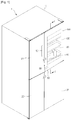
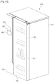
- FIG. 1 is a perspective view illustrating a refrigerator according to a first embodiment.
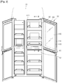
- FIG. 2 is a schematic view illustrating an open state of a door coupled with a second receiving part, according to the first embodiment.
- FIG. 3 is a schematic view illustrating an open state of the door without the second receiving part according to the first embodiment.
- FIG. 4 is a cross-sectional view taken along line II-II' of FIG. 3 .
- a refrigerator 1 includes a main body 10 that defines a freezing compartment 20 and a refrigerating compartment 30 as storage spaces.
- the freezing compartment 20 and the refrigerating compartment 30 are separated from each other by a partition 15, and are laterally arrayed in parallel.
- a first receiving part 70 for receiving items is disposed in the freezing compartment 20 and the refrigerating compartment 30.
- the first receiving part 70 includes a shelf.
- a first light emitting part 17 that emits light to the first receiving part 70 is disposed at the frontal edge portion of the main body 10.
- the first light emitting part 17 may be disposed around the frontal edge portion of the freezing compartment 20 and the refrigerating compartment 30, and may include a light emitting diode (LED).
- LED light emitting diode
- Compartment doors are rotatably disposed on the front surface of the main body 10 to selectively close the freezing compartment 20 and the refrigerating compartment 30.
- the compartment doors include a first freezing compartment door 21 and a second freezing compartment door 22, which close the freezing compartment 20.
- the second freezing compartment door 22 may be disposed under the first freezing compartment door 21.
- the compartment door further includes a first refrigerating compartment door 100 and a second refrigerating compartment door 32, which close the refrigerating compartment 30.
- the second refrigerating compartment door 32 may be disposed under the first refrigerating compartment door 100.
- Pressable opening-manipulators 40 may be disposed on the front surfaces of the freezing compartment doors 21 and 22 and the refrigerating compartment doors 32 and 100 to open the freezing compartment doors 21 and 22 and the refrigerating compartment doors 32 and 100.
- the front end of the main body 10 may be provided with opening mechanisms (not shown) that move in conjunction with the opening-manipulators 40.
- the opening mechanism moves a corresponding one of the doors 21, 22, 32 and 100 forward to open at least one portion of the freezing compartment 20 or the refrigerating compartment 30.
- a display unit 50 may be disposed on the first freezing compartment door 21 to display an operation state of the refrigerator 1 to the outside thereof.
- the display unit 50 may include input parts (not shown) to control an operation state of the refrigerator 1.
- a viewing window 105 may be disposed on the first refrigerating compartment door 100 to see the inside of the refrigerating compartment 30 from the outside thereof.
- the viewing window 105 may constitute at least one portion of the front surface of the first refrigerating compartment door 100.
- the first refrigerating compartment door 100 may be provided with a light emitting manipulator 90 that turns the first light emitting part 17 on.
- the light emitting manipulator 90 includes a button-type or touch-type input part.
- Sub-doors for receiving an item may be disposed behind the doors 21, 22, 100, and 32.
- the sub-doors include a sub-door provided to the freezing compartment 20 and a sub-door 80 provided to the refrigerating compartment 30, which may be rotatably connected to the front portions of the freezing compartment 20 and the refrigerating compartment 30, and may have a length corresponding to the length of the freezing compartment 20 and the length of the refrigerating compartment 30.
- the sub-doors are described with respect to the sub-door 80 provided to the refrigerating compartment 30, and the sub-door provided to the freezing compartment 20 may also be denoted by 80.
- the sub-door 80 may include a frame 81 having a size to be received in the freezing compartment 20 or the refrigerating compartment 30, a sub-door handle 82 protruding from the front surface of the frame 81, and second receiving parts.
- the frame 81 is tetragonal in which the second receiving part may be removably mounted.
- the sub-door handle 82 may horizontally extend on the front surface of the frame 81.
- the sub-door 80 may be removed from the freezing compartment doors 21 and 22 or the refrigerating compartment doors 32 and 100, and be disposed within the main body 10. That is, the sub-door 80 may be removed from the freezing compartment 20 or the refrigerating compartment 30 by rotating together with the freezing compartment doors 21 and 22 or the refrigerating compartment doors 32 and 100, or be disposed in the main body 10 when the freezing compartment doors 21 and 22 or the refrigerating compartment doors 32 and 100 are opened.
- the first refrigerating compartment door 100 and the first freezing compartment door 21 are provided with a door handle 60 that can be held to open the first refrigerating compartment door 100.
- the sub-door handle 82 is disposed behind the door handle 60, and may have a shape corresponding to the door handle 60.
- a third light emitting part 88 may be disposed within the sub-door handle 82.
- the third light emitting part 88 emits light to show the sub-door handle 82 in a dark indoor space.
- the sub-door handle 82 protrudes from approximately the central portion of the front surface of the sub-door 80, and may be integrally formed with the sub-door 80.
- a recess part may be recessed a predetermined depth upward from the bottom surface of the sub-door handle 82 to easily hold the sub-door handle 82.
- the front surface of the sub-door handle 82 is covered with the first refrigerating compartment door 100 and the first freezing compartment door 21, and thus, cannot be seen from the outside of the refrigerator 1.
- the recess part of the sub-door handle 82 can be held through a space formed between the first and second refrigerating compartment door 100 and 32 and a space formed between the first and second freezing compartment door 21 and 22.
- the doors 21, 22, 100, and 32 can be opened.
- the doors 21, 22, 100, and 32 and the sub-door 80 are simultaneously opened.
- the first and second refrigerating compartment doors 100 and 32 are closed, when the sub-door handle 82 is pulled out, the first and second refrigerating compartment doors 100 and 32 and the sub-door 80 are simultaneously opened.
- the first and second freezing compartment doors 21 and 22 are opened in the same manner as those of the first and second refrigerating compartment doors 100 and 32.
- the second receiving parts of the sub-door 80 may include a receiving basket 84 and a receiving drawer part 85 to receive items. When only the first and second refrigerating compartment doors 100 and 32 are opened, the receiving drawer part 85 can be pulled forward.
- the sub-door 80 includes a frontal edge portion 811 that constitutes a front border of the frame 81 when the sub-door 80 is disposed in the main body 10.
- the frontal edge portion 811 may be in close contact with the rear surfaces of the first and second refrigerating compartment doors 100 and 32 when the first and second refrigerating compartment doors 100 and 32 are closed.
- the inner surface of the frontal edge portion 811 is provided with a second light emitting part 87 that emits light to the center of the sub-door 80.
- the second light emitting part 87 may include an LED, and be operated by manipulating the light emitting manipulator 90.
- the second light emitting part 87 When the second light emitting part 87 is turned on, an item stored in the sub-door 80 can be seen from the outside through the viewing window 105.
- the light emitting manipulator 90 when the light emitting manipulator 90 is manipulated, the first light emitting part 17 and the second light emitting part 87 are turned on at the same time, which may be maintained for a preset time.
- the first and second light emitting parts 17 and 87 operate, items stored in the first receiving part 70 and the sub-door 80 can be seen from the outside through the viewing window 105.
- FIG. 5 is an exploded perspective view illustrating a first refrigerating compartment door according to the first embodiment.
- FIG. 6 is a cross-sectional view taken along line I-I' of FIG. 1 .
- the first refrigerating compartment door 100 includes an outer door part 110 defining an exterior of the first refrigerating compartment door 100, an inner door part 150 spaced rearward from the outer door part 110, and a door body 130 coupling the outer door part 110 and the inner door part 150 to each other.
- a border of the inner door part 150 is provided with a sealing member 160 that seals the space between the first refrigerating compartment door 100 and the sub-door 80.
- the outer door part 110 is provided with the viewing window 105 through which the inside of the refrigerator 1 can be seen from the outside.
- the outer door part 110 may be formed of transparent glass.
- the rear surface of the outer door part 110 is provided with a coupling surface 112 for coupling to the door body 130.
- the coupling surface 112 has a certain area along a border of the door body 130.
- the front surface of the door body 130 may be coupled to the coupling surface 112 using heat welding or supersonic welding.
- the present disclosure is not limited thereto, and thus, the door body 130 may be coupled to the outer door part 110 by a separate coupling member.
- the lower portion of the outer door part 110 is provided with a support 115 that supports the lower portion of the door body 130.
- the support 115 extends to the rear side of the outer door part 110.
- the door body 130 includes an insulating space 135 that has a hollow rectangle shape and functions as an insulating part for insulating the refrigerating compartment 30.
- the front portion of the insulating space 135 is covered by the outer door part 110.
- the outer door part 110 may be coupled to the front surface of the door body 130.
- the rear portion of the insulating space 135 is covered by the inner door part 150.
- the door body 130 includes a support rib 134 that supports the inner door part 150.
- the support rib 134 protrudes rearward around the insulating space 135.
- the inner door part 150 coupled to the rear portion of the door body 130 may be supported by at least one portion of the support rib 134. At this point, the inner door part 150 may be adhered to the support rib 134. In this case, the support rib 134 functions as a coupling rib.
- the insulating space 135 has a thickness corresponding to the thickness of the door body 130.
- an insulating gas layer may be formed in the insulating space 135.
- the insulating gas layer may include at least one of air, argon (Ar), and krypton (Kr), which have high insulating performance.
- the insulating space 135 may be maintained in a vacuum state. In this case, the insulating space 135 has no heat exchange medium, and thus, a heat exchange between the refrigerating compartment 30 and the outside can be minimized.
- a sealing coupling part 133 which is coupled with the sealing member 160, is disposed outside the support rib 134.
- the sealing member 160 is coupled to the sealing coupling part 133 to prevent a leakage of cool air through the space between the first refrigerating compartment door 100 and the sub-door 80.
- the door body 130 is provided with a door shoulder 132 that closely contacts the main body 10 when the first refrigerating compartment door 100 is closed on the main body 10.
- the door shoulder 132 mates with a main shoulder 19 (refer to FIG. 4 ), and is inclined in a certain direction.
- a sealing member may be disposed between the door shoulder 132 and the main shoulder 19.
- the inner door part 150 may include a transparent material to show the inside of the refrigerating compartment 30.
- the inner door part 150 may include a transparent plate that is formed of glass or plastic to fully transmit light.
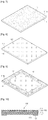
- FIGS. 7 to 9 are schematic views illustrating a process that is performed on an outer door part according to the first embodiment.
- FIG. 10 is a cross-sectional view illustrating a configuration of an outer door part according to the first embodiment.
- the glass member 111 may be formed of a transparent material.
- the transparent material may be defined as a material capable of fully transmitting light.
- a lamination treated layer 112 may be formed on a front surface 111a constituting the front surface of the glass member 111.
- the lamination treated layer 112 may be formed through a glass lamination process.
- the glass lamination process is a method for expressing various feelings according to lighting or a viewing angle, in which glass ink is applied on the glass member 111 and then is heated at a temperature ranging from about 600°C to about 700°C such that the glass ink soaks in the glass member 111.
- the lamination treated layer 112 includes a lamination layer 113, a reflective lamination layer 114, and a protective coating part 115.
- the lamination layer 113 may be printed using a silk screen lamination method, the so-called screen process.
- the silk screen lamination method makes it possible to freely express various colors and use various base materials, and is not limited in size and material.
- the front surface 111a of the glass member 111 may be colored silver or blue.
- the reflective lamination layer 114 is disposed on the upper side of the lamination layer 113 such that a color printed on the lamination layer 113 is displayed through the glass member 111 without a distortion. That is, the reflective lamination layer 114 is configured to increase the color reflectivity of light passing through the lamination layer 113.
- the reflective lamination layer 114 and the lamination layer 113 may reduce the transparency of the glass member 111.
- the reflective lamination layer 114 has a thickness ranging from about 10 ⁇ m to about 40 ⁇ m to reflect most of light passing through the lamination layer 113. When the reflectivity of light is improved, the intensity of the light reflected through the lamination layer 113 increases, and thus, a color of the lamination layer 113 is more vivid.
- a gradation effect of the glass member 111 can be attained using the reflective lamination layer 114.
- the protective coating part 115 may be formed of epoxy resin to protect the lamination layer 113 and the reflective lamination layer 114.
- the protective coating part 115 may be formed through laminating on the upper portion of the reflection lamination layer 114.
- the lamination treated layer 112 configured as described above has a predetermined color to screen the transparent glass member 111 to a predetermined extent, and thus, a predetermined pattern is formed on the glass member 111.
- the term 'screen' denotes making the glass member 111 opaque to a predetermined extent.
- a deposition process is performed on a rear surface 11 1b of the glass member 111.
- a deposition treated layer 116 is formed on the rear surface 11 1b.
- the term 'deposition treated' denotes processing an uneven surface of the glass member 111 to form an even (smooth) surface, and coloring a surface of the glass member 111. Since the deposition treated layer 116 is disposed on the glass member 111, a portion of light can be emitted from the inside of the refrigerating compartment 30 to the outside.
- the deposition treated layer 116 may be formed through an evaporation process.
- a metal source is heated, melted, and evaporated at a high temperature to be deposited on a base material (a wafer), that is, on the glass member 111.
- the evaporation process uses a principle that, when a metal is heated and evaporated at a high temperature for a short time, metal particles come out from the evaporated metal and are attached to a surface of a low temperature base material to form a thin metal film thereon.
- An electron beam may be used as an evaporating member in the evaporation process.
- a multi layer of a metal or metal oxide is heated, melted, and evaporated by the electron beam to form a film on a surface of a base material. Since the metal oxidizes at high temperature in the evaporation process, the evaporation process is performed in a vacuum state, and thus, may be called a vacuum evaporation process.
- the deposition treated layer 116 when the deposition treated layer 116 is formed on the glass member 111, an uneven surface of the glass member 111 is changed to a smooth surface, and thus, the outer door part 110 looks more luxurious.
- the metal or metal oxide may include SiO 2 or TiO 2 .
- the glass member 111 When SiO 2 is used as a source material to be deposited on the glass member 111, the glass member 111 may be colored approximately in blue. When TiO 2 is used as a source material to be deposited on the glass member 111, the glass member 110 may be colored approximately in silver. As described above, when SiO 2 or TiO 2 is used as a source material to be deposited on the glass member 111, the glass member 111 can be variously colored, and thus, the outer door part 110 can have a fancy color.
- direct glare of light emitted from the first light emitting part 17 and the second light emitting part 87 can be prevented. That is, since the transparency of the glass member 111 is decreased (increase of opacity), light emitted from the first light emitting part 17 and the second light emitting part 87 is perceived as soft light from the outside. Through the evaporation process, the glass member 111 is improved in hardness and corrosion resistance, and is more resistant to temperature and humidity variations. Although the rear surface 111b of the outer door part 110 is exposed to gas in the insulating space 135 for a long time, discoloration or decoloration thereof can be prevented.
- a sputtering process may be used as a depositing process for the glass member 111.
- plasma is formed by a high voltage generated from a voltage generating device such that plasma ions collide with a target to attach metal atoms to a base material, that is, to a surface of the glass member 111, thereby forming a metal film.
- argon (Ar+) gas may be used to form the plasma ions
- stannum (Sn) may be used as the target.
- the argon gas is ionized by a high voltage and collides with the stannum, particles coming out from the stannum are attached to the glass member 111 to form a metal film.
- aluminum (Al) may be used as the target. In this case, the argon gas collides with the aluminum, and particles coming out from the aluminum are attached to the glass member 111 to form a metal film.
- a screening layer 117 is formed on a border of the rear surface 111b.
- the screening layer 117 may be formed through the above-described lamination process, and may further make the glass member 111 opaque.
- the lamination process may be performed at several times for the screening layer 117 to effectively screen the glass member 111.
- the screening layer 117 formed on the rear surface 111b prevents the emission of light from the first and second light emitting parts 17 and 87 to the outside. That is, light emitted from the first and second light emitting parts 17 and 87 is reflected by the screening layer 117. Thus, the light emitted from the first and second light emitting parts 17 and 87 can be transmitted through the region of the deposition treated layer 116 except for the screening layer 117. As described above, since the deposition treated layer 116 has a predetermined color and opacity, the light emitted from the first and second light emitting parts 17 and 87 partially pass through the deposition treated layer 116.
- the viewing window 105 for showing the inside of the refrigerating compartment 30 may correspond to the region of the deposition treated layer 116.
- the light emitting manipulator 90 may be pressed to perceive items stored in the refrigerating compartment 30, that is, in the first receiving part 70 and the second receiving part of the sub-door 80.
- the first light emitting part 17 and the second light emitting part 87 may be turned on, and light emitted therefrom is transmitted by the inner door part 150 and the outer door part 110 which are formed of transparent materials, and is emitted to the outside.
- the deposition treated layer 116 and the lamination treated layer 112 which have predetermined colors and opacity, are disposed on the outer door part 110, a portion of the light emitted from the first and second light emitting parts 17 and 87 is reflected from the outer door part 110, and the other thereof is transmitted by the viewing window 105, and thus, is softly emitted to the outside.
- the items stored in the first receiving part 70 and the sub-door 80 can be perceived from the outside.
- the first light emitting part 17 and the second light emitting part 87 may be turned off, thereby reducing the power consumption thereof.
- the viewing window 105 is provided to the first refrigerating compartment door 100 in the current embodiment, the viewing window 105 may be provided to one of the first and second freezing compartment doors 21 and 22 according to another embodiment.
- an item stored in the freezing compartment 20 can be perceived from the outside.
- FIG. 11 is a perspective view illustrating a configuration of a refrigerator according to the second embodiment.
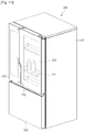
- FIG. 12 is a perspective view illustrating a configuration of a refrigerator according to a third embodiment.
- a refrigerator 200 includes a main body 210 defining a storage compartment, and doors 220 and 230 closing the storage compartment.
- the storage compartment includes a refrigerating compartment for storing an item under refrigeration, and a freezing compartment for storing an item under freezing.
- the doors 220 and 230 include refrigerating compartment doors (also denoted by 220) rotatably coupled to the front portion of the refrigerating compartment, and a freezing compartment door (also denoted by 230) closing the front portion of the freezing compartment.
- the refrigerator 200 is a bottom freezer type refrigerator in which a refrigerating compartment is disposed over a freezing compartment.
- the refrigerating compartment door 220 is provided with a viewing window 225 to perceive a receiving part 227 provided to the refrigerating compartment, from the outside of the refrigerator 200. Since the viewing window 225 is the same in configuration as the viewing window 105, a description thereof will be omitted.
- the lower portion of the refrigerating compartment door 220 is provided with a light emitting manipulator 250 that is manipulated to operate a light emitting part disposed in the refrigerating compartment.
- the light emitting part is disposed in the refrigerating compartment to emit light to an item stored in the receiving part 227.
- an item disposed in the refrigerating compartment can be perceived through the viewing window 225 by manipulating the light emitting manipulator 250 without opening the refrigerating compartment door 220.
- a refrigerator 300 includes a main body 310 defining a storage compartment, and doors 320 and 330 closing the storage compartment.
- the storage compartment includes a refrigerating compartment for storing an item under refrigeration, and a freezing compartment for storing an item under freezing.
- the doors 320 and 330 include a refrigerating compartment door (also denoted by 320) and a freezing compartment door (also denoted by 330), which are rotatably coupled to the front portions of the refrigerating compartment and the freezing compartment, respectively.
- the refrigerator 300 is a side by side type refrigerator in which a refrigerating compartment and a freezing compartment are disposed on the left and right sides.
- the refrigerating compartment door 320 is provided with a viewing window 325 to perceive a receiving part 327 provided to the refrigerating compartment, from the outside of the refrigerator 300. Since the viewing window 325 is the same in configuration as the viewing window 105, a description thereof will be omitted.
- the freezing compartment door 330 is provided with a light emitting manipulator 350 that can be manipulated to operate a light emitting part disposed in the refrigerating compartment.
- a display unit 340 for displaying an operation state of the refrigerator 300, an input part 342 for inputting a predetermined command for operating the refrigerator 300 are disposed at a side of the light emitting manipulator 350.
- an item disposed in the refrigerating compartment can be perceived through the viewing window 325 by manipulating the light emitting manipulator 350 without opening the refrigerating compartment door 320.
- the viewing window 325 is provided to the refrigerating compartment door 320 according to the current embodiment, the viewing window 325 may be provided to the freezing compartment door 330 according to another embodiment. In this case, an item disposed in the freezing compartment can be perceived from the outside without opening the freezing compartment door 330. In this case, the light emitting manipulator 350 may be provided to the refrigerating compartment door 320.
- FIG. 13 is a perspective view illustrating a refrigerator according to a fourth embodiment.
- FIGS. 14 and 15 are cross-sectional views illustrating a driving unit for driving a display unit of a refrigerator according to the fourth embodiment.
- FIG. 16 is a perspective view illustrating an operation of a viewing window of the refrigerator according to the fourth embodiment.
- the first refrigerating compartment door 100 includes the display unit 50 for displaying an operation state of a refrigerator, the light emitting manipulator 90 for manipulating the first and second light emitting parts 17 and 87 and the display unit 50, and input parts 92 for commanding the refrigerator to operate.
- the display unit 50 may be disposed in a region corresponding to the viewing window 105.
- the display unit 50 is displayed to the outside of the refrigerator, and it is difficult to see the inside of the refrigerating compartment 30.
- the input part 92 is manipulated to input a command for operating the refrigerator, for example, a command for controlling a temperature of the freezing compartment 20 and a temperature of the refrigerating compartment 30, and a command for operating a special refrigerating compartment.
- the display unit 50 or the first and second light emitting parts 17 and 87 may be selectively turned on or off.
- An operation (control) method related with these on/off operations will be described later with reference to drawings.
- the rear surface of the first refrigerating compartment door 100 is provided with a driving unit 400 for driving the display unit 50.
- the driving unit 400 may be disposed in the insulating space 135.
- the driving unit 400 includes: an upper plate 420 and a lower plate 460, which spaced apart from each other and are vertically arrayed; a first transparent conductor 430 disposed under the upper plate 420; a second transparent conductor 450 disposed over the lower plate 460; and a liquid crystal layer 440 disposed between the first and second transparent conductors 430 and 450.
- the upper plate 420 and the lower plate 460 may be formed of transparent glass or plastic, which fully transmit light.
- the first and second transparent conductors 430 and 450 are transparent electrodes for driving the liquid crystal layer 440, and may be formed of indium tin oxide (ITO).
- the first and second transparent conductors 430 and 450 may have predetermined conductivity and transmissivity.
- the first and second transparent conductors 430 and 450 may be driven as positive and negative electrodes by power supplied from a power supply 490, and thus, an alignment of the liquid crystal layer 440 is determined in a predetermined direction according to the driving of the first and second transparent conductors 430 and 450.
- the first and second transparent conductors 430 and 450 may constitute one of pixels including a plurality of electrodes. When power is applied to a part of the electrodes, an alignment of the liquid crystal layer 440 corresponding to the part of the electrodes is determined in a predetermined direction.
- a character or a numeral displayed on the display unit 50 is expressed in a specific shape by the driving of the first and second transparent conductors 430 and 450 constituted in a pixel unit, and the driving of the liquid crystal layer 440 corresponding to the first and second transparent conductors 430 and 450.
- a vibration direction of light may be determined according to an alignment degree of the liquid crystal layer 440, for example, according to an alignment angle from a vertical axis.
- a first polarizing plate 412 is disposed over the upper plate 420, and a second polarizing plate 414 is disposed under the lower plate 460, and uses polarization as a property of light to transmit light having only a predetermined direction.
- light passing through the first polarizing plate 412 may be polarized vertically with respect to an optical axis
- light passing through the second polarizing plate 414 may be polarized horizontally with respect to the optical axis.
- the liquid crystal layer 440, the first and second transparent conductors 430 and 450, the first and second polarizing plates 212 and 214, and the upper and lower plates 420 and 460 may constitute an LCD panel.
- Backlights 480 for emitting light and a light guide panel 470 are disposed under the second polarizing plate 414.
- the light guide panel 470 is disposed between the backlights 480 to guide light emitted from the back light units 480 to the LCD panel, that is, to the liquid crystal layer 440.
- the backlights 480 and the light guide panel 470 may constitute a backlight unit.
- the light guide panel 470 uniformly transmits the light to the liquid crystal layer 440.
- the light transmitted by the light guide panel 470 is filtered by the second polarizing plate 414, so that only light having a first direction passes through the second polarizing plate 414.
- the light passing through the second polarizing plate 414 is transmitted to the liquid crystal layer 440 through the lower plate 460.
- the liquid crystal layer 440 is driven by the first and second transparent conductors 430 and 450, and an alignment thereof is determined in a preset direction.
- the light passing through the liquid crystal layer 440 may change its direction to a direction different from the first direction.
- the light is transmitted from the liquid crystal layer 440 to the upper plate 420 and the first polarizing plate 412. At this point, only light having a second direction passes through the first polarizing plate 412.
- a vibration direction of the light passing through the liquid crystal layer 440 is the same as the second direction of the first polarizing plate 412, the light entirely passes through the first polarizing plate 412, and thus, a white color can be seen.
- a vibration direction of the light passing through the liquid crystal layer 440 is perpendicular to the second direction of the first polarizing plate 412, the light is blocked by the first polarizing plate 412, and thus, a black color can be seen.
- a white or black color can be seen on the display unit 50 according to an alignment of the liquid crystal layer 440 and a vibration direction of light emitted from the backlights 480.
- a color filter may be disposed on the upper plate 420. In this case, light passing through the upper plate 420 may have a predetermined color.
- a character (numeral) or a figure displayed on the display unit 50 may be formed by driving of the liquid crystal layer 440 and the filtering of light through the first and second polarizing plates 412 and 414.
- the display unit 50 When power applied to the first and second transparent conductors 430 and 450 is cut off, and the backlights 480 are turned off, light just passes through the driving unit 400. In this case, information (character and figure) to be displayed through the display unit 50 are transparent, and thus, is invisible on the first refrigerating compartment door 100.
- the display unit 50 transmits the light to the outside of the first refrigerating compartment door 100.
- the display unit 50 is invisible on the first refrigerating compartment door 100, and items stored in the first receiving part 70 and the sub-door 80 can be seen through the viewing window 105 from the outside.
- the display unit 50 is displayed on the first refrigerating compartment door 100.
- the light emitting manipulator 90 may be pressed to perceive items stored in the refrigerating compartment 30, that is, in the first receiving part 70 and the second receiving part (also denoted by 80).
- the first and second light emitting parts 17 and 87 may be turned on, and light emitted from the first and second light emitting parts 17 and 87 may be transmitted to the outside by the transparent inner door part 150 and the transparent outer door part 110.
- the light emitting manipulator 90 may be manipulated to perceive an item in the refrigerating compartment 30, the light emitting manipulator 90 may be called a viewing conversion input switch.
- the deposition treated layer 116 and the lamination treated layer 112 which have predetermined colors and opacity, are disposed on the outer door part 110, a portion of light emitted from the first and second light emitting parts 17 and 87 is reflected from the outer door part 110, and the other is emitted through the viewing window 105, and thus, soft light is emitted to the outside.
- the items stored in the first receiving part 70 and the sub-door 80 can be perceived from the outside.
- the first light emitting part 17 and the second light emitting part 87 may be turned off, thereby reducing the power consumption thereof.
- the viewing window 105 is provided to the first refrigerating compartment door 100 in the current embodiment, the viewing window 105 may be provided to one of the first and second freezing compartment doors 21 and 22 according to another embodiment.
- an item stored in the freezing compartment 20 can be perceived from the outside.
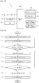
- FIG. 17 is a block diagram illustrating a configuration of a refrigerator according to an embodiment.
- FIG. 18 is a flowchart illustrating a method for controlling a refrigerator according to an embodiment.
- the refrigerator 1 includes the input part 92 for inputting a predetermined command to the display unit 50, the light emitting manipulator 90 for turning the first and second light emitting parts 17 and 87 on to perceive an item stored in the refrigerating compartment 30, and a timer 320 used to count a duration time that the light emitting manipulator 90 is stayed on.
- the refrigerator 1 includes the driving unit 400 for driving the display unit 50, the first light emitting part 17 for emitting light to the first receiving part 70, and the second light emitting part 87 for emitting light to the receiving part 80.
- the driving unit 400 includes the power supply 490 for applying power to the first and second transparent conductors 430 and 450, and the backlights 480 disposed behind the liquid crystal layer 440 to emit predetermined light.
- the refrigerator 1 includes a control unit 300.
- the control unit 300 controls the driving unit 400 and the first and second light emitting parts 17 and 87 according to commands input from the input part 92 and the light emitting manipulator 90.
- the display unit 50 When the first refrigerating compartment door 100 is closed in operation S11, the display unit 50 is turned on to display an operation state of a refrigerator on the front side of the viewing window 105.
- the display unit 50 may be turned on even when the first refrigerating compartment door 100 is opened.
- the driving unit 400 is driven to apply power to the power supply 490, and the backlights 480 emit light to the light guide panel 470, the display unit 50 is turned on in operation S12.
- Light emitted from the first and second light emitting parts 17 and 87 passes through the driving unit 400, the display unit 50, and the viewing window 105, and is emitted to the outside. At this point, the items stored in the first and second receiving parts 70 and 80 can be shown to the outside in operation S16.
- operation S12 is repeated. That is, the display unit 50 stays on.
- the driving unit 400 is operated again to turn the display unit 50 on in operation S19. That is, power is applied to the power supply 490 to drive the first and second transparent conductors 430 and 450 and the liquid crystal layer 440, and light is emitted from the backlights 480 to the liquid crystal layer 440.
- the time measured by the timer 320 is not over the set time, the items are continually shown to the outside.
- an operation state of the refrigerator 1 can be checked.
- the light emitting manipulator 90 is manipulated to perceive an item in the refrigerator 1, the display unit 50 disappears, and the first and second light emitting parts 17 and 87 are operated.
- the refrigerator 1 can be conveniently used, thereby satisfying users.
- a lining layer having high coefficient of friction may be attached to a wheel of an auxiliary wheel to prevent a slip, or a rough surface such as knurling may be provided thereto, or a plurality of wheels may be combined.
Landscapes
- Engineering & Computer Science (AREA)
- Physics & Mathematics (AREA)
- Thermal Sciences (AREA)
- Chemical & Material Sciences (AREA)
- Combustion & Propulsion (AREA)
- Mechanical Engineering (AREA)
- General Engineering & Computer Science (AREA)
- Cold Air Circulating Systems And Constructional Details In Refrigerators (AREA)
- Refrigerator Housings (AREA)
Claims (14)
- Kühlschrank, der Folgendes umfasst:einen Hauptkörper (10), der ein Vorratsfach (20, 30) definiert;ein lichtemittierendes Element (17, 87), das ein erstes lichtemittierendes Element (17) zum Emittieren von Licht in das Vorratsfach (20, 30) aufweist;eine Tür (21, 22, 32, 100), die das Vorratsfach (20, 30) wahlweise öffnet oder schließt und mit einem Sichtfenster (105) versehen ist, um einen Innenraum des Vorratsfachs von außen betrachten zu können; undeine zusätzliche Tür (80) zum Aufnehmen eines Gegenstands, die hinter der Tür (21, 22,32, 100) angeordnet ist, wobei die zusätzliche Tür (80) einen Rahmen (81) und einen vorderen Kantenabschnitt (811), der eine vordere Grenze des Rahmens (81) bildet, umfasst;wobei die Tür (21, 22, 32, 100) Folgendes umfasst:ein inneres Türelement (150), das Licht von dem lichtemittierenden Element (17,87) durchlässt;ein äußeres Türelement (110), das Licht, das durch das innere Türelement (150) gelangt ist, durchlässt und das mit dem Sichtfenster (105) versehen ist; undeinen Zwischenraum zwischen dem inneren Türelement (150) und dem äußeren Türelement (110), der mit Gas zur Isolierung gefüllt ist,wobei das lichtemittierende Element (17, 87) ein zweites lichtemittierendes Element (87) aufweist, das an einer inneren Oberfläche des vorderen Kantenabschnitts (811) der zusätzlichen Tür (80) vorgesehen ist und konfiguriert ist, Licht zur Mitte der zusätzlichen Tür (80) zu emittieren, undwobei dann, wenn das lichtemittierende Element (17, 87) eingeschaltet ist und die Tür (21, 22, 32, 100) geschlossen ist, bei einer frontalen Betrachtung der Tür ein Gegenstand in dem Vorratsfach (20, 30) durch das Sichtfenster (105) wahrgenommen werden kann.
- Kühlschrank nach Anspruch 1, wobei das äußere Türelement (110) Folgendes umfasst:ein lichtdurchlässiges Glaselement (111); undeine abgeschiedene Schicht (116), die auf einer Oberfläche (111a) des Glaselements (111) ausgebildet ist.
- Kühlschrank nach Anspruch 2, wobei das äußere Türelement (110) ferner Folgendes umfasst:eine durch Laminieren erzeugte Schicht (112), die an der äußeren Oberfläche (111b) des Glaselements (111) angeordnet ist, um zu ermöglichen, dass eine zuvor ausgewählte Farbe sichtbar ist; undeine Schutzschicht (117), die auf einen Teil der durch Abscheiden erzeugten Schicht (112) gedruckt ist, um Licht von dem lichtemittierenden Element (17, 87) zu reflektieren,wobei eine innere Fläche des Glaselements (111), die durch die Schutzschicht (117) gebildet ist, als das Sichtfenster (105) definiert ist.
- Kühlschrank nach Anspruch 1, wobei die Tür (21, 22, 32, 100) ferner einen Türkörper (130) umfasst, der zwischen dem inneren Türelement (150) und dem äußeren Türelement (110) angeordnet ist,
wobei der Türkörper (130) mit einer Schulter (132) ausgebildet ist, die mit dem Hauptkörper (10) in direktem Kontakt ist. - Kühlschrank nach Anspruch 1, wobei die zusätzliche Tür (80) so konfiguriert ist, dass sie sich an einer Rückseite der Tür (21, 22, 32, 100) dreht.
- Kühlschrank nach Anspruch 5, wobei eine Drehachse der Tür (21, 22, 32, 100) parallel zu einer Drehachse der zusätzlichen Tür (80) verläuft und wobei eine Drehrichtung der Tür (21, 22, 32, 100) gleich jener der zusätzlichen Tür (80) ist.
- Kühlschrank nach Anspruch 6, der ferner Folgendes umfasst:ein Griffelement (82), das an einem vorderen Teil der zusätzlichen Tür (80) ausgebildet ist; undein drittes lichtemittierendes Element (88), das in dem Griffelement (82) montiert ist.
- Kühlschrank nach Anspruch 1, wobei der Rahmen (81) eine Größe hat, derart, dass er in dem Vorratsfach (20,30) aufgenommen werden kann.
- Kühlschrank nach Anspruch 8, wobei der Rahmen (81) tetragonal ist, wobei ein Element zum Aufnehmen eines Gegenstands bei der zusätzlichen Tür (80) abnehmbar montiert ist.
- Kühlschrank nach Anspruch 1, der ferner Folgendes umfasst:
ein erstes lichtemittierendes Element (17), das an einem vorderen Kantenabschnitt des Hauptkörpers (10) angeordnet ist. - Kühlschrank nach Anspruch 10, wobei das erste lichtemittierende Element und das zweite lichtemittierende Element so konfiguriert sind, dass sie durch Betätigung eines Bedienelements (90) zum Emittieren von Licht gleichzeitig eingeschaltet werden.
- Kühlschrank nach Anspruch 10, wobei dann, wenn eine festgelegte Zeitspanne verstrichen ist, das erste lichtemittierende Element (17) und das zweite lichtemittierende Element (87) ausgeschaltet werden.
- Kühlschrank nach Anspruch 1, wobei die zusätzliche Tür (80) an dem Kühlfach (30) vorgesehen ist.
- Kühlschrank nach Anspruch 1, wobei das innere Türelement (150) eine lichtdurchlässige Platte umfasst, die aus Glas oder Kunststoff gebildet ist.
Priority Applications (5)
| Application Number | Priority Date | Filing Date | Title |
|---|---|---|---|
| EP17162812.6A EP3205957B1 (de) | 2010-02-01 | 2011-01-19 | Kühlschrank |
| EP17162819.1A EP3232145B1 (de) | 2010-02-01 | 2011-01-19 | Kühlschrank |
| EP22190935.1A EP4109016A1 (de) | 2010-02-01 | 2011-01-19 | Kühlschrank |
| EP19200363.0A EP3614081B1 (de) | 2010-02-01 | 2011-01-19 | Kühlschrank |
| EP17162829.0A EP3205958B1 (de) | 2010-02-01 | 2011-01-19 | Kühlschrank |
Applications Claiming Priority (3)
| Application Number | Priority Date | Filing Date | Title |
|---|---|---|---|
| KR1020100008978A KR101297029B1 (ko) | 2010-02-01 | 2010-02-01 | 냉장고 및 냉장고의 제어방법 |
| KR1020100008977A KR101325818B1 (ko) | 2010-02-01 | 2010-02-01 | 냉장고 |
| PCT/KR2011/000374 WO2011093614A2 (en) | 2010-02-01 | 2011-01-19 | Refrigerator and method for controlling the same |
Related Child Applications (9)
| Application Number | Title | Priority Date | Filing Date |
|---|---|---|---|
| EP17162819.1A Division EP3232145B1 (de) | 2010-02-01 | 2011-01-19 | Kühlschrank |
| EP17162819.1A Division-Into EP3232145B1 (de) | 2010-02-01 | 2011-01-19 | Kühlschrank |
| EP17162829.0A Division EP3205958B1 (de) | 2010-02-01 | 2011-01-19 | Kühlschrank |
| EP17162829.0A Division-Into EP3205958B1 (de) | 2010-02-01 | 2011-01-19 | Kühlschrank |
| EP17162812.6A Division EP3205957B1 (de) | 2010-02-01 | 2011-01-19 | Kühlschrank |
| EP17162812.6A Division-Into EP3205957B1 (de) | 2010-02-01 | 2011-01-19 | Kühlschrank |
| EP22190935.1A Division EP4109016A1 (de) | 2010-02-01 | 2011-01-19 | Kühlschrank |
| EP19200363.0A Division EP3614081B1 (de) | 2010-02-01 | 2011-01-19 | Kühlschrank |
| EP19200363.0A Division-Into EP3614081B1 (de) | 2010-02-01 | 2011-01-19 | Kühlschrank |
Publications (3)
| Publication Number | Publication Date |
|---|---|
| EP2531789A2 EP2531789A2 (de) | 2012-12-12 |
| EP2531789A4 EP2531789A4 (de) | 2018-04-18 |
| EP2531789B1 true EP2531789B1 (de) | 2020-05-13 |
Family
ID=44319959
Family Applications (6)
| Application Number | Title | Priority Date | Filing Date |
|---|---|---|---|
| EP17162829.0A Active EP3205958B1 (de) | 2010-02-01 | 2011-01-19 | Kühlschrank |
| EP11737253.2A Active EP2531789B1 (de) | 2010-02-01 | 2011-01-19 | Kühlschrank und steuerungsverfahren dafür |
| EP22190935.1A Pending EP4109016A1 (de) | 2010-02-01 | 2011-01-19 | Kühlschrank |
| EP19200363.0A Active EP3614081B1 (de) | 2010-02-01 | 2011-01-19 | Kühlschrank |
| EP17162812.6A Active EP3205957B1 (de) | 2010-02-01 | 2011-01-19 | Kühlschrank |
| EP17162819.1A Active EP3232145B1 (de) | 2010-02-01 | 2011-01-19 | Kühlschrank |
Family Applications Before (1)
| Application Number | Title | Priority Date | Filing Date |
|---|---|---|---|
| EP17162829.0A Active EP3205958B1 (de) | 2010-02-01 | 2011-01-19 | Kühlschrank |
Family Applications After (4)
| Application Number | Title | Priority Date | Filing Date |
|---|---|---|---|
| EP22190935.1A Pending EP4109016A1 (de) | 2010-02-01 | 2011-01-19 | Kühlschrank |
| EP19200363.0A Active EP3614081B1 (de) | 2010-02-01 | 2011-01-19 | Kühlschrank |
| EP17162812.6A Active EP3205957B1 (de) | 2010-02-01 | 2011-01-19 | Kühlschrank |
| EP17162819.1A Active EP3232145B1 (de) | 2010-02-01 | 2011-01-19 | Kühlschrank |
Country Status (9)
| Country | Link |
|---|---|
| US (11) | US9046294B2 (de) |
| EP (6) | EP3205958B1 (de) |
| CN (1) | CN102472555A (de) |
| AU (1) | AU2011210123B2 (de) |
| BR (1) | BR112012006216B1 (de) |
| CA (1) | CA2760815A1 (de) |
| MX (1) | MX2011013055A (de) |
| RU (1) | RU2513414C1 (de) |
| WO (1) | WO2011093614A2 (de) |
Families Citing this family (95)
| Publication number | Priority date | Publication date | Assignee | Title |
|---|---|---|---|---|
| EP3205958B1 (de) * | 2010-02-01 | 2019-11-13 | LG Electronics Inc. | Kühlschrank |
| DE202011000856U1 (de) * | 2011-04-13 | 2011-08-10 | Flextronics Automotive Gmbh & Co.Kg | Anzeigevorrichtung für die Kühlschranktemperatur |
| US9052536B2 (en) * | 2011-05-10 | 2015-06-09 | Anthony, Inc. | Display case door with transparent LCD panel |
| US10252490B2 (en) | 2011-07-18 | 2019-04-09 | Rilco Manufacturing Company, Inc. | Method and system for reinforced pipe insulation |
| DE102011079796B4 (de) | 2011-07-26 | 2015-08-13 | Flextronics Automotive Gmbh & Co.Kg | Verfahren zur Ermittlung von PWM-Werten für LED-Module |
| EP4209737A1 (de) * | 2011-08-05 | 2023-07-12 | LG Electronics Inc. | Kühlschrank mit innentür |
| DE102012201089A1 (de) * | 2012-01-25 | 2013-07-25 | BSH Bosch und Siemens Hausgeräte GmbH | Kältegerät mit einem kältefach |
| NL1039440C2 (nl) * | 2012-03-06 | 2013-09-09 | Polyplastic Groep B V | Koelinrichting en toegangsdeur. |
| ES1077250Y (es) * | 2012-04-18 | 2012-09-18 | Crambo Sa | Maquina de venta con elemento lcd translucido incorporado |
| DE102012208599A1 (de) * | 2012-05-23 | 2013-11-28 | BSH Bosch und Siemens Hausgeräte GmbH | Kältegerät, insbesondere Haushaltskältegerät |
| CN103423957B (zh) * | 2012-05-23 | 2017-03-01 | 海尔集团公司 | 冰箱信息读取提示方法及系统 |
| US9366394B2 (en) | 2012-06-27 | 2016-06-14 | Flextronics Ap, Llc | Automotive LED headlight cooling system |
| DE102012213979A1 (de) * | 2012-08-07 | 2014-02-13 | BSH Bosch und Siemens Hausgeräte GmbH | Kältegerät mit Eisbereiter |
| GB201216928D0 (en) | 2012-09-21 | 2012-11-07 | I2R Medical Ltd | Portable medical device system |
| KR102025734B1 (ko) * | 2012-11-09 | 2019-09-27 | 삼성전자주식회사 | 냉장고 및 그 내부 도어의 제조 방법 |
| KR102025177B1 (ko) * | 2012-11-09 | 2019-09-26 | 삼성전자주식회사 | 냉장고 및 그 내부 도어의 제조 방법 |
| KR101860713B1 (ko) * | 2013-02-23 | 2018-05-24 | 삼성전자주식회사 | 슬라이딩 장치 및 이를 갖는 냉장고 |
| US9748460B2 (en) | 2013-02-28 | 2017-08-29 | Flextronics Ap, Llc | LED back end assembly and method of manufacturing |
| US9574817B2 (en) * | 2013-03-15 | 2017-02-21 | Helmer, Inc. | Medical products storage device with viewing window having variable opacity |
| KR101728196B1 (ko) | 2013-04-26 | 2017-04-18 | 엘지전자 주식회사 | 냉장고 |
| KR102218918B1 (ko) * | 2013-06-14 | 2021-02-23 | 엘지전자 주식회사 | 냉장고 |
| WO2015105332A1 (ko) | 2014-01-07 | 2015-07-16 | 삼성전자주식회사 | 냉장고 |
| JP6406748B2 (ja) * | 2014-01-27 | 2018-10-17 | 株式会社ミヤデン | 電気冷蔵庫 |
| KR102186243B1 (ko) * | 2014-02-28 | 2020-12-03 | 엘지전자 주식회사 | 냉장고 |
| DE102014206723A1 (de) * | 2014-04-08 | 2015-10-08 | BSH Hausgeräte GmbH | Tür mit transparenten Platten für ein Haushaltskältegerät sowie Haushaltskältegerät |
| JP6227500B2 (ja) * | 2014-08-07 | 2017-11-08 | 日立アプライアンス株式会社 | 冷蔵庫 |
| DE202014104855U1 (de) * | 2014-10-13 | 2016-01-15 | Rehau Ag + Co | Tür, insbesondere für ein Kühl- und / oder Gefriergerät |
| KR101646514B1 (ko) * | 2014-10-15 | 2016-08-08 | 엘지전자 주식회사 | 냉장고 |
| KR20160045545A (ko) | 2014-10-17 | 2016-04-27 | 엘지전자 주식회사 | 냉장고 |
| DE102015203150A1 (de) * | 2015-02-23 | 2016-08-25 | BSH Hausgeräte GmbH | Haushaltskältegerät und Verfahren zum Betreiben eines Haushaltskältegerätes |
| DE102015003018B4 (de) * | 2015-03-06 | 2019-03-28 | Emz-Hanauer Gmbh & Co. Kgaa | Kühl- oder/und Gefrierschrank mit türseitig angeordneter Leuchtvorrichtung |
| CN111426124A (zh) | 2015-06-11 | 2020-07-17 | Lg 电子株式会社 | 冰箱 |
| KR102098689B1 (ko) | 2015-07-08 | 2020-04-08 | 삼성전자주식회사 | 냉장고 |
| KR102562149B1 (ko) * | 2015-07-14 | 2023-08-01 | 엘지전자 주식회사 | 냉장고용 도어 및 냉장고 |
| US10228182B2 (en) * | 2015-07-15 | 2019-03-12 | Lg Electronics Inc. | Door for home appliance, home appliance, and method for manufacturing the same |
| DE102015213319A1 (de) * | 2015-07-16 | 2017-01-19 | BSH Hausgeräte GmbH | Kältegerät mit einer Entnahmetür |
| CN105318636A (zh) * | 2015-11-06 | 2016-02-10 | 上海九山电子科技有限公司 | 半透明液晶显示冷柜门 |
| KR102417751B1 (ko) * | 2015-11-12 | 2022-07-07 | 삼성전자주식회사 | 냉장고 |
| KR101954874B1 (ko) | 2016-01-05 | 2019-05-30 | 엘지전자 주식회사 | 냉장고 |
| KR101916720B1 (ko) | 2016-01-05 | 2018-11-08 | 엘지전자 주식회사 | 배터리 모듈 및 그 제조방법, 배터리 모듈을 이용한 전기 자동차 |
| TW201725351A (zh) * | 2016-01-05 | 2017-07-16 | Lwo Technology Co Ltd | 電器的門板裝置 |
| KR101810760B1 (ko) | 2016-01-05 | 2017-12-19 | 엘지전자 주식회사 | 냉장고 및 냉장고의 제어 방법 |
| KR101856835B1 (ko) | 2016-01-05 | 2018-05-10 | 엘지전자 주식회사 | 냉장고 |
| CN105627676A (zh) * | 2016-03-01 | 2016-06-01 | 上海九山电子科技有限公司 | 自带半透明液晶发光结构的冷柜门及其制造方法 |
| EP3441705B1 (de) * | 2016-04-04 | 2022-03-30 | LG Electronics Inc. | Haushaltsgerät |
| CN106016889A (zh) * | 2016-05-20 | 2016-10-12 | 青岛海尔股份有限公司 | 冰箱及其制造方法 |
| JP6326450B2 (ja) * | 2016-06-02 | 2018-05-16 | 日立アプライアンス株式会社 | 冷蔵庫 |
| US9696084B1 (en) * | 2016-09-15 | 2017-07-04 | Haier Us Appliance Solutions, Inc. | Light switch for door in door refrigerator |
| KR102345097B1 (ko) * | 2016-11-29 | 2021-12-31 | 엘지전자 주식회사 | 냉장고 |
| KR102601889B1 (ko) * | 2016-12-12 | 2023-11-15 | 엘지전자 주식회사 | 냉장고 |
| KR102602658B1 (ko) * | 2016-12-12 | 2023-11-16 | 엘지전자 주식회사 | 냉장고 |
| US10295248B2 (en) * | 2017-01-09 | 2019-05-21 | Electrolux Home Products, Inc. | Refrigerator with glass door |
| JP2018123996A (ja) * | 2017-01-31 | 2018-08-09 | 東芝ライフスタイル株式会社 | 冷蔵庫 |
| KR102259753B1 (ko) | 2017-03-24 | 2021-06-02 | 엘지전자 주식회사 | 냉장고 |
| US10684065B2 (en) * | 2017-06-26 | 2020-06-16 | Samsung Electronics Co., Ltd. | Refrigerator |
| US10672032B2 (en) | 2017-08-10 | 2020-06-02 | Cooler Screens Inc. | Intelligent marketing and advertising platform |
| US12118510B2 (en) | 2017-08-10 | 2024-10-15 | Cooler Screens Inc. | Intelligent marketing and advertising platform |
| US11768030B2 (en) | 2017-08-10 | 2023-09-26 | Cooler Screens Inc. | Smart movable closure system for cooling cabinet |
| US11763252B2 (en) | 2017-08-10 | 2023-09-19 | Cooler Screens Inc. | Intelligent marketing and advertising platform |
| US11698219B2 (en) | 2017-08-10 | 2023-07-11 | Cooler Screens Inc. | Smart movable closure system for cooling cabinet |
| US10769666B2 (en) | 2017-08-10 | 2020-09-08 | Cooler Screens Inc. | Intelligent marketing and advertising platform |
| CA3087353A1 (en) | 2018-01-17 | 2019-07-25 | Anthony, Inc. | Door for mounting a removable electronic display |
| US20190316826A1 (en) * | 2018-04-13 | 2019-10-17 | Haier Us Appliance Solutions, Inc. | Side-by-side refrigerator appliance with freezer in door |
| EP3575715B1 (de) | 2018-05-28 | 2025-06-25 | LG Electronics Inc. | Kühlschrank |
| CN109442840A (zh) * | 2018-10-31 | 2019-03-08 | 郑州韦尔特生物科技有限公司 | 一种生物技术用细胞培养冷藏箱 |
| CN111121382B (zh) * | 2018-12-13 | 2025-02-14 | 宁波泰格莱特灯具有限公司 | 一种可连接冷柜灯 |
| US11386621B2 (en) * | 2018-12-31 | 2022-07-12 | Whirlpool Corporation | Augmented reality feedback of inventory for an appliance |
| US10514722B1 (en) | 2019-03-29 | 2019-12-24 | Anthony, Inc. | Door for mounting a removable electronic display |
| IT201900005460A1 (it) * | 2019-04-09 | 2020-10-09 | Paolo Michele Soggiu | Sportello di un’apparecchiatura di conservazione a bassa temperatura del settore alimentare |
| US11116333B2 (en) | 2019-05-07 | 2021-09-14 | Carrier Corporation | Refrigerated display cabinet including microchannel heat exchangers |
| US11559147B2 (en) | 2019-05-07 | 2023-01-24 | Carrier Corporation | Refrigerated display cabinet utilizing a radial cross flow fan |
| US11000133B2 (en) * | 2019-09-27 | 2021-05-11 | Pepsico, Inc. | Vacuum-insulated cooler |
| KR20220099951A (ko) * | 2019-11-28 | 2022-07-14 | 엘지전자 주식회사 | 냉장고 |
| AU2020396667B2 (en) | 2019-12-05 | 2024-04-11 | Lg Electronics Inc. | Refrigerator |
| US11473835B2 (en) * | 2020-04-06 | 2022-10-18 | Electrolux Home Products, Inc. | Glass front door with embedded user interface |
| KR20220030124A (ko) * | 2020-09-02 | 2022-03-10 | 엘지전자 주식회사 | 냉장고 |
| JP1720852S (ja) * | 2020-11-12 | 2022-07-28 | 履物洗浄・手入れ用キャビネット | |
| JP1720847S (ja) * | 2020-11-12 | 2022-07-27 | 履物手入れ機 | |
| USD1093035S1 (en) * | 2020-11-13 | 2025-09-16 | Lg Electronics Inc. | Footwear care machine |
| US11668513B2 (en) | 2020-12-01 | 2023-06-06 | Electrolux Home Products, Inc. | Staged access door for a home appliance |
| US11215391B1 (en) | 2020-12-01 | 2022-01-04 | Electrolux Home Products, Inc. | Staged access door for a home appliance |
| US11768025B2 (en) * | 2021-02-11 | 2023-09-26 | Stephanie E Thoen | Compartment drawer refrigerator freezer |
| AU2022205217B2 (en) * | 2021-07-13 | 2024-05-30 | Lg Electronics Inc. | Panel assembly for a home appliance and home appliance therewith |
| KR20230011155A (ko) * | 2021-07-13 | 2023-01-20 | 엘지전자 주식회사 | 냉장고 및 가전기기 |
| JP7728667B2 (ja) * | 2021-08-02 | 2025-08-25 | 富士フイルム株式会社 | 筐体構造、及び画像形成装置 |
| CN114870320A (zh) * | 2021-08-10 | 2022-08-09 | 广东飞匠科技有限公司 | 具有u形弹性杆的弹跳型装置 |
| KR20230071576A (ko) * | 2021-11-16 | 2023-05-23 | 엘지전자 주식회사 | 가전기기 |
| US12429275B2 (en) * | 2021-11-16 | 2025-09-30 | Lg Electronics Inc. | Home appliance |
| KR20230071579A (ko) * | 2021-11-16 | 2023-05-23 | 엘지전자 주식회사 | 가전 기기 |
| CN116138599A (zh) * | 2021-11-19 | 2023-05-23 | 青岛海高设计制造有限公司 | 冰箱 |
| KR20230092118A (ko) * | 2021-12-17 | 2023-06-26 | 엘지전자 주식회사 | 냉장고 및 가전기기 |
| USD1099993S1 (en) | 2022-02-07 | 2025-10-28 | Pepsico, Inc. | Cooler |
| US12460826B2 (en) | 2022-12-21 | 2025-11-04 | Bsh Home Appliances Corporation | Interlocking dual side hinge door for a domestic kitchen appliance |
| KR20250130145A (ko) * | 2024-02-23 | 2025-09-01 | 엘지전자 주식회사 | 가전기기용 도어 및 이를 포함하는 가전기기 |
| JP7714273B1 (ja) * | 2025-02-14 | 2025-07-29 | 株式会社シンシ | 冷蔵庫用ドア及び冷蔵庫 |
Family Cites Families (158)
| Publication number | Priority date | Publication date | Assignee | Title |
|---|---|---|---|---|
| US215064A (en) | 1879-05-06 | Improvement in slide and steam valves | ||
| US1275511A (en) * | 1918-02-23 | 1918-08-13 | James Welch | Refrigerator. |
| US1927398A (en) | 1933-01-07 | 1933-09-19 | Harold A Glasser | Refrigerator |
| US2150064A (en) * | 1933-02-08 | 1939-03-07 | Boots | Refrigerator |
| US2131680A (en) | 1934-02-05 | 1938-09-27 | Crosley Radio Corp | Refrigerator |
| US2122680A (en) * | 1934-03-08 | 1938-07-05 | William F Dart | Refrigeration means |
| US2051132A (en) | 1934-03-08 | 1936-08-18 | Crosley Radio Corp | Refrigerator door |
| US2095811A (en) | 1934-03-30 | 1937-10-12 | Kelvinator Corp | Refrigerating apparatus |
| US2112771A (en) | 1934-03-30 | 1938-03-29 | Nash Kelvinator Corp | Refrigerating apparatus |
| US2046909A (en) | 1934-09-26 | 1936-07-07 | Merrill H Terry | Refrigerator door |
| US2135878A (en) | 1935-07-05 | 1938-11-08 | Nash Kelvinator Corp | Refrigerating apparatus |
| US2130617A (en) | 1936-03-23 | 1938-09-20 | Hazel L Groves | Refrigerator |
| US2129923A (en) | 1936-11-18 | 1938-09-13 | Fairbanks Morse & Co | Refrigerator cabinet |
| US2213274A (en) | 1937-10-07 | 1940-09-03 | Alexander L Flamm | Refrigerator |
| US2276937A (en) | 1941-05-06 | 1942-03-17 | Cordova Arturo | Refrigerator |
| US2339085A (en) * | 1943-04-10 | 1944-01-11 | Gen Electric | Refrigerator |
| US2381598A (en) * | 1944-03-18 | 1945-08-07 | Philco Corp | Refrigerator cabinet construction |
| US2453387A (en) * | 1947-01-04 | 1948-11-09 | Philco Corp | Article supporting closure for cabinets |
| US2653851A (en) * | 1947-05-03 | 1953-09-29 | Avco Mfg Corp | Cabinet having improved means for facilitating opening doors singly or in multiple |
| US2644882A (en) * | 1950-10-28 | 1953-07-07 | Int Harvester Co | Illuminated handle for refrigerated cabinet doors |
| US2692813A (en) | 1951-03-22 | 1954-10-26 | Peter A Toronto | Auxiliary refrigerator shelf |
| US2942438A (en) * | 1955-11-23 | 1960-06-28 | Gen Motors Corp | Refrigerator |
| US2995649A (en) * | 1958-03-26 | 1961-08-08 | Westinghouse Electric Corp | Refrigeration apparatus |
| US3086830A (en) * | 1960-06-09 | 1963-04-23 | Malia John Peter | Compartmentalized refrigerator |
| US3140134A (en) | 1961-12-21 | 1964-07-07 | Mark A Nairn | Cabinet |
| FR1347720A (fr) * | 1962-10-15 | 1964-01-04 | Disposition d'armoires à capacités multiples | |
| US3218111A (en) * | 1964-01-27 | 1965-11-16 | Gen Motors Corp | Refrigerating apparatus |
| US3314196A (en) * | 1965-04-23 | 1967-04-18 | Gen Motors Corp | Insulated door |
| US3389424A (en) | 1966-11-14 | 1968-06-25 | Whirlpool Co | Reversible hinges for refrigerator door |
| US3510986A (en) | 1968-10-01 | 1970-05-12 | Kason Hardware Corp | Self-closing hinged doors and hinges therefor |
| US3726578A (en) * | 1971-11-12 | 1973-04-10 | Gen Electric | Convertible side-by-side refrigerator |
| US3836221A (en) * | 1973-10-09 | 1974-09-17 | Gen Motors Corp | Refrigerator door with removably mounted radio |
| US4072486A (en) * | 1976-11-03 | 1978-02-07 | Ruth Joseph | See-through, smoked gray, plexiglass refrigerator door |
| US4087140A (en) | 1977-04-14 | 1978-05-02 | Whirlpool Corporation | Magnetic latch - movable ice receptacle |
| CA1126785A (en) | 1978-10-13 | 1982-06-29 | Jose Massana Canals | Personal security door arrangement |
| JPS56164495U (de) | 1980-05-10 | 1981-12-05 | ||
| JPS56164495A (en) | 1980-05-20 | 1981-12-17 | Ricoh Kk | Signal detecting circuit |
| US4382177A (en) * | 1980-09-15 | 1983-05-03 | Heaney James J | Substantially transparent insulating anti-condensation structure |
| US4368622A (en) | 1981-05-14 | 1983-01-18 | General Electric Company | Refrigerator with through-the-door quick-chilling service |
| DE3215607A1 (de) | 1982-04-27 | 1983-10-27 | Paul Hettich & Co, 4983 Kirchlengern | Schrank mit einer aus einerinnentuer und einer aussentuer bestehenden doppeltuer. |
| US4728915A (en) | 1986-03-18 | 1988-03-01 | Matsushita Electronics Corporation | Deflection yoke for a color cathode ray tube |
| KR900008203Y1 (ko) | 1986-09-02 | 1990-09-03 | 삼성전자 주식회사 | 냉장고 좌우 가변 힌지구조 |
| JPS63142682A (ja) | 1986-12-05 | 1988-06-15 | Fujitsu Ltd | 電界効果半導体装置 |
| JPS63142682U (de) | 1987-03-09 | 1988-09-20 | ||
| US5048233A (en) * | 1987-05-01 | 1991-09-17 | Northland Corporation | Refrigerator door and method of manufacturing same |
| JPS63295034A (ja) | 1987-05-28 | 1988-12-01 | Sanshu Press Kogyo Kk | ポリvプーリの製造方法 |
| US4893902A (en) | 1987-06-25 | 1990-01-16 | Allied-Signal Inc. | Dual-pane thermal window with liquid crystal shade |
| US5111618A (en) * | 1989-12-11 | 1992-05-12 | Ardco, Inc. | Refrigerator door assembly with stylized substantially all glass front |
| KR930000043Y1 (ko) | 1991-01-29 | 1993-01-09 | 삼성전자 주식회사 | 복합 냉장고의 신선실 구조 |
| ES1017395Y (es) * | 1991-05-13 | 1992-06-16 | S.A. De Fabricantes De Electrodomesticos (Safel) | Tirador de puerta de frigorifico. |
| US5486044A (en) * | 1992-02-10 | 1996-01-23 | Bennett; James L. | Cooler door display rack |
| JPH0666473A (ja) | 1992-08-15 | 1994-03-08 | Matsumoto Sakiko | 冷蔵庫・冷凍庫の二重扉 |
| US5376455A (en) * | 1993-10-05 | 1994-12-27 | Guardian Industries Corp. | Heat-treatment convertible coated glass and method of converting same |
| KR960011364B1 (ko) | 1993-12-02 | 1996-08-22 | 삼성건설 주식회사 | 철골철근 콘크리트보의 하부형틀 고정방법 |
| US5412839A (en) * | 1994-01-07 | 1995-05-09 | General Electric Company | Soft touch appliance handle assembly |
| KR970007503B1 (ko) | 1994-09-15 | 1997-05-09 | 엘지전자 주식회사 | 냉장고의 도어잠금장치 |
| US5589958A (en) * | 1995-02-09 | 1996-12-31 | Lieb; Joseph A. | Kitchen ensemble having windows with controllable opacity |
| US5600966A (en) * | 1995-05-19 | 1997-02-11 | Forma Scientific, Inc. | Ultra low temperature split door freezer |
| JPH0961045A (ja) * | 1995-08-24 | 1997-03-07 | Takashi Wakabayashi | 冷蔵庫 |
| US5830529A (en) * | 1996-01-11 | 1998-11-03 | Ross; Gregory E. | Perimeter coating alignment |
| JPH109757A (ja) | 1996-06-26 | 1998-01-16 | Matsushita Refrig Co Ltd | 冷蔵庫 |
| KR19980052430A (ko) | 1996-12-24 | 1998-09-25 | 김영환 | 캐패시터 내장형 패키지 장치 |
| BR9806016A (pt) | 1997-07-03 | 1999-10-13 | Gen Electric | Centro de refrigeração modular para compartimento de alimento fresco em um refrigerador |
| JPH11136111A (ja) | 1997-10-30 | 1999-05-21 | Sony Corp | 高周波回路 |
| KR19990039593A (ko) | 1997-11-13 | 1999-06-05 | 윤종용 | 포토레지스트 플로우 공정에 사용되는 배기장치 |
| KR19990042339A (ko) * | 1997-11-26 | 1999-06-15 | 윤종용 | 냉장고 |
| KR19990062159A (ko) | 1997-12-31 | 1999-07-26 | 윤종용 | 냉장고 |
| KR19990037440U (ko) * | 1998-03-05 | 1999-10-05 | 윤종용 | 냉장고 |
| KR200314145Y1 (ko) | 1998-04-11 | 2003-08-21 | 삼성전자주식회사 | 냉장고의홈바록킹장치 |
| US6085542A (en) * | 1998-06-30 | 2000-07-11 | Maytag Corporation | Refrigerator door storage system |
| US5966963A (en) | 1998-07-30 | 1999-10-19 | Kovalaske; Kenneth A. | Refrigerator with a third door |
| JP2000065459A (ja) * | 1998-08-25 | 2000-03-03 | Fujitsu General Ltd | 冷凍冷蔵庫 |
| DE19844046C2 (de) | 1998-09-25 | 2001-08-23 | Schott Glas | Mehrscheibenisolierglas |
| KR100301632B1 (ko) | 1998-11-30 | 2001-11-22 | 전주범 | 투명창을구비한냉장고 |
| US6059420A (en) * | 1999-02-17 | 2000-05-09 | Rogers; Thomas | See through refrigerator door construction |
| JP2000241070A (ja) * | 1999-02-22 | 2000-09-08 | Kazuichi Kusakabe | 冷蔵室内が見える家庭用冷蔵庫 |
| US7976916B2 (en) | 1999-05-25 | 2011-07-12 | Saint-Gobain Vitrage | Refrigerated display case having a transparent insulating glazing unit |
| KR200164322Y1 (ko) | 1999-07-13 | 2000-02-15 | 삼성전자주식회사 | 냉장고의 보조도어용 힌지 |
| US6193340B1 (en) | 1999-08-03 | 2001-02-27 | Geographics, Inc. | Snap-together file storage system |
| KR200168373Y1 (ko) * | 1999-08-30 | 2000-02-15 | 이정희 | 절전형 냉장고 |
| KR100596533B1 (ko) | 1999-09-04 | 2006-07-06 | 삼성전자주식회사 | 냉장고의 도어 핸들장치 |
| JP2001108357A (ja) | 1999-10-04 | 2001-04-20 | Hideyuki Machida | 冷蔵庫 |
| KR20010037549A (ko) | 1999-10-18 | 2001-05-15 | 구자홍 | 내부 투시기능을 구비한 냉장고 |
| US6406108B1 (en) * | 1999-11-05 | 2002-06-18 | Specialty Equipment Companies, Inc. | Display case with door-mounted internal lighting |
| JP2001280821A (ja) * | 2000-03-29 | 2001-10-10 | Mikio Ryuzaki | 中身の見える冷蔵庫 |
| JP2001280820A (ja) * | 2000-03-31 | 2001-10-10 | Sanyo Electric Co Ltd | 冷蔵庫 |
| KR100408201B1 (ko) | 2000-04-19 | 2003-12-01 | 일동화학 주식회사 | 아지도기를 고분자 측쇄에 가지는 수용성 포토레지스터고분자 및 이의 제조방법 |
| US20020060511A1 (en) | 2000-11-23 | 2002-05-23 | Jian Ma | Glass-door icebox |
| DE10115196A1 (de) * | 2001-03-27 | 2002-10-17 | Pilkington Deutschland Ag | Glasscheibe als Vorprodukt für eine thermisch vorgespannte und/oder gebogene Glasscheibe mit Sonnenschutz- und/oder Low-E-Beschichtung |
| KR100376167B1 (ko) | 2001-04-18 | 2003-03-15 | 삼성전자주식회사 | 냉온장고 |
| JP3336000B1 (ja) | 2001-04-25 | 2002-10-21 | 株式会社日立製作所 | 冷蔵庫 |
| US6833158B2 (en) | 2001-08-09 | 2004-12-21 | Canon Kabushiki Kaisha | Coating apparatus and coating method of liquid for protection of recorded product, and protection process of recorded product |
| DE10207990A1 (de) * | 2002-02-25 | 2003-09-04 | Bsh Bosch Siemens Hausgeraete | Einbaukältegerät mit lichtdurchlässiger Tür |
| KR100887575B1 (ko) * | 2002-04-22 | 2009-03-09 | 엘지전자 주식회사 | 이중도어를 구비한 냉장고 |
| KR20030083813A (ko) | 2002-04-22 | 2003-11-01 | 엘지전자 주식회사 | 이중도어를 구비한 냉장고 |
| KR100884946B1 (ko) | 2002-05-29 | 2009-02-23 | 엘지전자 주식회사 | 김치 냉장고 |
| EP1581777B1 (de) * | 2002-12-31 | 2010-09-22 | Arçelik A.S. | Kühlschrank |
| JP2004211977A (ja) * | 2003-01-06 | 2004-07-29 | Sanyo Electric Co Ltd | 内扉付き貯蔵庫 |
| JP2004225968A (ja) | 2003-01-21 | 2004-08-12 | Mitsubishi Automob Eng Co Ltd | 冷蔵庫 |
| US6722142B1 (en) * | 2003-02-07 | 2004-04-20 | Sub-Zero Freezer Company, Inc. | Refrigerated enclosure |
| US7186969B2 (en) * | 2003-02-12 | 2007-03-06 | Mitutoyo Corporation | Optical configuration for imaging-type optical encoders |
| TR200502342T1 (tr) * | 2003-03-24 | 2005-09-21 | Arçeli̇k Anoni̇m Şi̇rketi̇ | Ev cihazı |
| DE10324854A1 (de) * | 2003-06-02 | 2004-12-23 | BSH Bosch und Siemens Hausgeräte GmbH | Tür mit Isolierverglasung und damit ausgestattetes Haushaltsgerät |
| CA2438766C (en) | 2003-08-29 | 2008-12-30 | Maytag Corporation | Refrigerator incorporating french doors with rotating mullion bar |
| JP4334401B2 (ja) * | 2003-10-21 | 2009-09-30 | 三洋電機株式会社 | 低温貯蔵庫 |
| CN100397009C (zh) | 2003-12-12 | 2008-06-25 | 乐金电子(天津)电器有限公司 | 冰箱的冷藏室瓶框门安装结构 |
| US7111363B2 (en) | 2004-02-26 | 2006-09-26 | Lotte Engineering & Machinery Mfg., Co., Ltd. | Door hinge structure for refrigerator |
| KR20050111094A (ko) | 2004-05-21 | 2005-11-24 | 삼성전자주식회사 | 냉장고 |
| JP2006038437A (ja) | 2004-07-24 | 2006-02-09 | Haruo Wakabayashi | 冷蔵庫 |
| JP4208783B2 (ja) * | 2004-07-28 | 2009-01-14 | キヤノン株式会社 | 画像処理装置および設定時刻調整方法およびプログラム |
| US7360374B2 (en) * | 2004-08-11 | 2008-04-22 | Larose Jr Leo D | Refrigerated display merchandiser with light filter |
| US7673467B2 (en) * | 2004-08-11 | 2010-03-09 | Larose Jr Leo D | Refrigerated display merchandiser with light filter |
| CN101035945A (zh) * | 2004-08-27 | 2007-09-12 | 阿塞里克股份有限公司 | 家用设备 |
| NZ554581A (en) * | 2004-09-20 | 2011-03-31 | Agc Flat Glass Na Inc | Anti-fog refrigeration door and method of making the same |
| ITMI20040455U1 (it) * | 2004-10-08 | 2005-01-08 | Thermo Glass Door S P A | Anta luminosa per espositori in particolare per frigoriferi provvisti di detta anta |
| DE202004019865U1 (de) | 2004-11-29 | 2006-04-06 | Liebherr-Hausgeräte Lienz Gmbh | Kühl- und/oder Gefriergerät |
| US8092660B2 (en) * | 2004-12-03 | 2012-01-10 | Cardinal Cg Company | Methods and equipment for depositing hydrophilic coatings, and deposition technologies for thin films |
| US8562089B2 (en) * | 2005-01-12 | 2013-10-22 | Whirlpool Corporation | Refrigerator shelf retainer and divider assembly for tall packages |
| DE202005002231U1 (de) * | 2005-01-25 | 2006-06-08 | Liebherr-Hausgeräte Ochsenhausen GmbH | Kühl- und/oder Gefriergerät |
| FR2881819B1 (fr) * | 2005-02-09 | 2012-11-23 | Saint Gobain | Guichet ouvrant en verre pour une installation refrigeree telle qu'un refrigerateur et installation refrigeree equipee d'un tel guichet |
| DE102005016566A1 (de) * | 2005-04-11 | 2006-10-12 | BSH Bosch und Siemens Hausgeräte GmbH | Verfahren zum Waschen von schrumpfgefährdeten Textilien und Waschmaschine zum Durchführen desselben |
| KR20060116349A (ko) * | 2005-05-09 | 2006-11-15 | 엘지전자 주식회사 | 냉장고의 홈바도어 |
| DE102005021590A1 (de) * | 2005-05-10 | 2006-11-16 | BSH Bosch und Siemens Hausgeräte GmbH | Kältegerät mit Rahmenheizung |
| KR100733309B1 (ko) | 2005-05-20 | 2007-06-28 | 엘지전자 주식회사 | 냉장고의 도어 개폐 장치 |
| US20070018548A1 (en) | 2005-05-27 | 2007-01-25 | Maytag Corporation | Refrigerator storage system |
| DE102005027200A1 (de) * | 2005-06-13 | 2007-02-08 | BSH Bosch und Siemens Hausgeräte GmbH | Hausgerätetür |
| CA2623126A1 (en) | 2005-09-20 | 2007-03-29 | Agc Flat Glass North America, Inc. | Anti-fog refrigeration door and method of making the same |
| BRPI0616377A2 (pt) | 2005-09-20 | 2011-06-21 | Agc Flat Glass Na Inc | porta de refrigeração antinévoa e método de feitura da mesma |
| DE102005055682A1 (de) * | 2005-11-22 | 2007-05-24 | Giesecke & Devrient Gmbh | Vorrichtung für die Überprüfung der Echtheit von Banknoten |
| DE102005057154A1 (de) * | 2005-11-30 | 2007-05-31 | BSH Bosch und Siemens Hausgeräte GmbH | Haushaltsgerät mit einem von einer Glastür her beleuchteten Innenraum |
| US7568358B2 (en) * | 2006-01-09 | 2009-08-04 | Maytag Corporation | Control for a refrigerator door dispenser light |
| US20080020387A1 (en) * | 2006-03-31 | 2008-01-24 | Lawrence Donald G | Biomarker-optimized adhd treatment |
| KR101357496B1 (ko) * | 2006-07-05 | 2014-02-03 | 엘지전자 주식회사 | 냉장고의 입력장치 |
| KR101275568B1 (ko) * | 2006-10-24 | 2013-06-14 | 엘지전자 주식회사 | 자동홈바 |
| KR101291206B1 (ko) * | 2007-02-26 | 2013-07-31 | 삼성전자주식회사 | 냉장고 |
| KR101347575B1 (ko) * | 2007-03-28 | 2014-01-03 | 삼성전자주식회사 | 디스플레이장치 |
| KR20080090783A (ko) * | 2007-04-06 | 2008-10-09 | 삼성전자주식회사 | 냉장고 |
| KR20080108686A (ko) * | 2007-06-11 | 2008-12-16 | 주식회사 대우일렉트로닉스 | 냉장고 투시창 자동제어 시스템 및 그 자동제어 방법 |
| KR20090014048A (ko) * | 2007-08-03 | 2009-02-06 | 엘지전자 주식회사 | 전자제품의 트림킷 도어 어셈블리 |
| WO2009027443A2 (en) * | 2007-08-31 | 2009-03-05 | Arcelik Anonim Sirketi | A cooling device |
| US7820309B2 (en) * | 2007-09-14 | 2010-10-26 | Cardinal Cg Company | Low-maintenance coatings, and methods for producing low-maintenance coatings |
| JP2009103395A (ja) | 2007-10-25 | 2009-05-14 | Mitsubishi Electric Corp | 冷蔵庫 |
| WO2009061069A1 (en) * | 2007-11-05 | 2009-05-14 | Lg Electronics Inc. | Refrigerator and opening/closing door thereof |
| JP5340582B2 (ja) * | 2007-11-22 | 2013-11-13 | 三洋電機株式会社 | ショーケース |
| KR101203424B1 (ko) | 2008-01-11 | 2012-11-21 | 삼성전자주식회사 | 냉장고 |
| KR101517230B1 (ko) * | 2008-02-21 | 2015-05-04 | 엘지전자 주식회사 | 냉장고 및 냉장고 도어 |
| KR101455861B1 (ko) * | 2008-02-21 | 2014-11-03 | 엘지전자 주식회사 | 냉장고 및 냉장고 도어 핸들 |
| JP2009236366A (ja) * | 2008-03-26 | 2009-10-15 | Nikkei Panel System Kk | 冷蔵庫 |
| US20090244884A1 (en) | 2008-03-31 | 2009-10-01 | True Manufacturing Co. Inc. | Glass door merchandiser having led lights and mounting assembly therefor |
| KR20090105246A (ko) * | 2008-04-02 | 2009-10-07 | 엘지전자 주식회사 | 냉장고의 외장부품 |
| EP2308244B1 (de) | 2008-07-28 | 2012-05-30 | Koninklijke Philips Electronics N.V. | Audiosystem und betriebsverfahren dafür |
| KR101602431B1 (ko) | 2008-11-05 | 2016-03-10 | 삼성전자 주식회사 | 냉장고 |
| DE102008044302A1 (de) | 2008-12-03 | 2010-06-10 | BSH Bosch und Siemens Hausgeräte GmbH | Kältegerätekorpus mit Innenbeleuchtung |
| KR20100122155A (ko) * | 2009-05-12 | 2010-11-22 | 엘지전자 주식회사 | 냉장고 |
| KR20100122152A (ko) * | 2009-05-12 | 2010-11-22 | 엘지전자 주식회사 | 냉장고 |
| KR101307681B1 (ko) * | 2009-06-03 | 2013-09-12 | 엘지전자 주식회사 | 냉장고 |
| EP2267386A3 (de) * | 2009-06-22 | 2014-01-29 | Samsung Electronics Co., Ltd. | Kühlschrank |
| EP3205958B1 (de) * | 2010-02-01 | 2019-11-13 | LG Electronics Inc. | Kühlschrank |
-
2011
- 2011-01-19 EP EP17162829.0A patent/EP3205958B1/de active Active
- 2011-01-19 EP EP11737253.2A patent/EP2531789B1/de active Active
- 2011-01-19 EP EP22190935.1A patent/EP4109016A1/de active Pending
- 2011-01-19 US US13/390,946 patent/US9046294B2/en active Active
- 2011-01-19 EP EP19200363.0A patent/EP3614081B1/de active Active
- 2011-01-19 WO PCT/KR2011/000374 patent/WO2011093614A2/en not_active Ceased
- 2011-01-19 EP EP17162812.6A patent/EP3205957B1/de active Active
- 2011-01-19 CN CN2011800026364A patent/CN102472555A/zh active Pending
- 2011-01-19 MX MX2011013055A patent/MX2011013055A/es active IP Right Grant
- 2011-01-19 RU RU2011147478/13A patent/RU2513414C1/ru active
- 2011-01-19 AU AU2011210123A patent/AU2011210123B2/en active Active
- 2011-01-19 CA CA2760815A patent/CA2760815A1/en not_active Abandoned
- 2011-01-19 BR BR112012006216-6A patent/BR112012006216B1/pt active IP Right Grant
- 2011-01-19 EP EP17162819.1A patent/EP3232145B1/de active Active
-
2015
- 2015-05-29 US US14/724,980 patent/US9510696B2/en active Active
- 2015-10-29 US US14/926,498 patent/US9516955B2/en active Active
- 2015-11-05 US US14/933,313 patent/US9516956B2/en active Active
-
2016
- 2016-07-15 US US15/212,123 patent/US10271668B2/en active Active
-
2019
- 2019-03-11 US US16/298,119 patent/US10568441B2/en active Active
- 2019-03-11 US US16/298,145 patent/US10575661B2/en active Active
- 2019-03-11 US US16/298,097 patent/US10568440B2/en not_active Ceased
- 2019-06-24 US US16/449,853 patent/US10758063B2/en active Active
-
2020
- 2020-01-17 US US16/745,811 patent/US10856672B2/en active Active
-
2022
- 2022-02-18 US US17/675,332 patent/USRE50294E1/en active Active
Non-Patent Citations (1)
| Title |
|---|
| None * |
Also Published As
Similar Documents
| Publication | Publication Date | Title |
|---|---|---|
| USRE50294E1 (en) | Refrigerator and method for controlling the same | |
| EP3553428B1 (de) | Kühlschrank | |
| KR101297029B1 (ko) | 냉장고 및 냉장고의 제어방법 |
Legal Events
| Date | Code | Title | Description |
|---|---|---|---|
| PUAI | Public reference made under article 153(3) epc to a published international application that has entered the european phase |
Free format text: ORIGINAL CODE: 0009012 |
|
| 17P | Request for examination filed |
Effective date: 20111104 |
|
| AK | Designated contracting states |
Kind code of ref document: A2 Designated state(s): AL AT BE BG CH CY CZ DE DK EE ES FI FR GB GR HR HU IE IS IT LI LT LU LV MC MK MT NL NO PL PT RO RS SE SI SK SM TR |
|
| DAX | Request for extension of the european patent (deleted) | ||
| RIC1 | Information provided on ipc code assigned before grant |
Ipc: F25D 23/02 20060101AFI20171106BHEP Ipc: F25D 29/00 20060101ALI20171106BHEP Ipc: F25D 23/06 20060101ALI20171106BHEP Ipc: F25D 23/04 20060101ALI20171106BHEP Ipc: F25D 25/02 20060101ALN20171106BHEP Ipc: F25D 27/00 20060101ALI20171106BHEP |
|
| A4 | Supplementary search report drawn up and despatched |
Effective date: 20180315 |
|
| RIC1 | Information provided on ipc code assigned before grant |
Ipc: F25D 29/00 20060101ALI20180309BHEP Ipc: F25D 23/04 20060101ALI20180309BHEP Ipc: F25D 25/02 20060101ALN20180309BHEP Ipc: F25D 23/06 20060101ALI20180309BHEP Ipc: F25D 27/00 20060101ALI20180309BHEP Ipc: F25D 23/02 20060101AFI20180309BHEP |
|
| STAA | Information on the status of an ep patent application or granted ep patent |
Free format text: STATUS: EXAMINATION IS IN PROGRESS |
|
| 17Q | First examination report despatched |
Effective date: 20190418 |
|
| GRAP | Despatch of communication of intention to grant a patent |
Free format text: ORIGINAL CODE: EPIDOSNIGR1 |
|
| STAA | Information on the status of an ep patent application or granted ep patent |
Free format text: STATUS: GRANT OF PATENT IS INTENDED |
|
| RIC1 | Information provided on ipc code assigned before grant |
Ipc: F25D 23/02 20060101AFI20191129BHEP Ipc: F25D 29/00 20060101ALI20191129BHEP Ipc: F25D 27/00 20060101ALI20191129BHEP Ipc: F25D 23/06 20060101ALI20191129BHEP Ipc: F25D 25/02 20060101ALN20191129BHEP Ipc: F25D 23/04 20060101ALI20191129BHEP |
|
| INTG | Intention to grant announced |
Effective date: 20191217 |
|
| RAP1 | Party data changed (applicant data changed or rights of an application transferred) |
Owner name: LG ELECTRONICS INC. |
|
| GRAS | Grant fee paid |
Free format text: ORIGINAL CODE: EPIDOSNIGR3 |
|
| GRAA | (expected) grant |
Free format text: ORIGINAL CODE: 0009210 |
|
| STAA | Information on the status of an ep patent application or granted ep patent |
Free format text: STATUS: THE PATENT HAS BEEN GRANTED |
|
| AK | Designated contracting states |
Kind code of ref document: B1 Designated state(s): AL AT BE BG CH CY CZ DE DK EE ES FI FR GB GR HR HU IE IS IT LI LT LU LV MC MK MT NL NO PL PT RO RS SE SI SK SM TR |
|
| REG | Reference to a national code |
Ref country code: GB Ref legal event code: FG4D |
|
| REG | Reference to a national code |
Ref country code: CH Ref legal event code: EP |
|
| REG | Reference to a national code |
Ref country code: DE Ref legal event code: R096 Ref document number: 602011066838 Country of ref document: DE |
|
| REG | Reference to a national code |
Ref country code: AT Ref legal event code: REF Ref document number: 1270829 Country of ref document: AT Kind code of ref document: T Effective date: 20200615 |
|
| REG | Reference to a national code |
Ref country code: LT Ref legal event code: MG4D |
|
| REG | Reference to a national code |
Ref country code: NL Ref legal event code: MP Effective date: 20200513 |
|
| PG25 | Lapsed in a contracting state [announced via postgrant information from national office to epo] |
Ref country code: PT Free format text: LAPSE BECAUSE OF FAILURE TO SUBMIT A TRANSLATION OF THE DESCRIPTION OR TO PAY THE FEE WITHIN THE PRESCRIBED TIME-LIMIT Effective date: 20200914 Ref country code: FI Free format text: LAPSE BECAUSE OF FAILURE TO SUBMIT A TRANSLATION OF THE DESCRIPTION OR TO PAY THE FEE WITHIN THE PRESCRIBED TIME-LIMIT Effective date: 20200513 Ref country code: IS Free format text: LAPSE BECAUSE OF FAILURE TO SUBMIT A TRANSLATION OF THE DESCRIPTION OR TO PAY THE FEE WITHIN THE PRESCRIBED TIME-LIMIT Effective date: 20200913 Ref country code: SE Free format text: LAPSE BECAUSE OF FAILURE TO SUBMIT A TRANSLATION OF THE DESCRIPTION OR TO PAY THE FEE WITHIN THE PRESCRIBED TIME-LIMIT Effective date: 20200513 Ref country code: GR Free format text: LAPSE BECAUSE OF FAILURE TO SUBMIT A TRANSLATION OF THE DESCRIPTION OR TO PAY THE FEE WITHIN THE PRESCRIBED TIME-LIMIT Effective date: 20200814 Ref country code: NO Free format text: LAPSE BECAUSE OF FAILURE TO SUBMIT A TRANSLATION OF THE DESCRIPTION OR TO PAY THE FEE WITHIN THE PRESCRIBED TIME-LIMIT Effective date: 20200813 Ref country code: LT Free format text: LAPSE BECAUSE OF FAILURE TO SUBMIT A TRANSLATION OF THE DESCRIPTION OR TO PAY THE FEE WITHIN THE PRESCRIBED TIME-LIMIT Effective date: 20200513 |
|
| PG25 | Lapsed in a contracting state [announced via postgrant information from national office to epo] |
Ref country code: BG Free format text: LAPSE BECAUSE OF FAILURE TO SUBMIT A TRANSLATION OF THE DESCRIPTION OR TO PAY THE FEE WITHIN THE PRESCRIBED TIME-LIMIT Effective date: 20200813 Ref country code: LV Free format text: LAPSE BECAUSE OF FAILURE TO SUBMIT A TRANSLATION OF THE DESCRIPTION OR TO PAY THE FEE WITHIN THE PRESCRIBED TIME-LIMIT Effective date: 20200513 Ref country code: RS Free format text: LAPSE BECAUSE OF FAILURE TO SUBMIT A TRANSLATION OF THE DESCRIPTION OR TO PAY THE FEE WITHIN THE PRESCRIBED TIME-LIMIT Effective date: 20200513 Ref country code: HR Free format text: LAPSE BECAUSE OF FAILURE TO SUBMIT A TRANSLATION OF THE DESCRIPTION OR TO PAY THE FEE WITHIN THE PRESCRIBED TIME-LIMIT Effective date: 20200513 |
|
| REG | Reference to a national code |
Ref country code: AT Ref legal event code: MK05 Ref document number: 1270829 Country of ref document: AT Kind code of ref document: T Effective date: 20200513 |
|
| PG25 | Lapsed in a contracting state [announced via postgrant information from national office to epo] |
Ref country code: NL Free format text: LAPSE BECAUSE OF FAILURE TO SUBMIT A TRANSLATION OF THE DESCRIPTION OR TO PAY THE FEE WITHIN THE PRESCRIBED TIME-LIMIT Effective date: 20200513 Ref country code: AL Free format text: LAPSE BECAUSE OF FAILURE TO SUBMIT A TRANSLATION OF THE DESCRIPTION OR TO PAY THE FEE WITHIN THE PRESCRIBED TIME-LIMIT Effective date: 20200513 |
|
| PG25 | Lapsed in a contracting state [announced via postgrant information from national office to epo] |
Ref country code: EE Free format text: LAPSE BECAUSE OF FAILURE TO SUBMIT A TRANSLATION OF THE DESCRIPTION OR TO PAY THE FEE WITHIN THE PRESCRIBED TIME-LIMIT Effective date: 20200513 Ref country code: AT Free format text: LAPSE BECAUSE OF FAILURE TO SUBMIT A TRANSLATION OF THE DESCRIPTION OR TO PAY THE FEE WITHIN THE PRESCRIBED TIME-LIMIT Effective date: 20200513 Ref country code: DK Free format text: LAPSE BECAUSE OF FAILURE TO SUBMIT A TRANSLATION OF THE DESCRIPTION OR TO PAY THE FEE WITHIN THE PRESCRIBED TIME-LIMIT Effective date: 20200513 Ref country code: RO Free format text: LAPSE BECAUSE OF FAILURE TO SUBMIT A TRANSLATION OF THE DESCRIPTION OR TO PAY THE FEE WITHIN THE PRESCRIBED TIME-LIMIT Effective date: 20200513 Ref country code: SM Free format text: LAPSE BECAUSE OF FAILURE TO SUBMIT A TRANSLATION OF THE DESCRIPTION OR TO PAY THE FEE WITHIN THE PRESCRIBED TIME-LIMIT Effective date: 20200513 Ref country code: CZ Free format text: LAPSE BECAUSE OF FAILURE TO SUBMIT A TRANSLATION OF THE DESCRIPTION OR TO PAY THE FEE WITHIN THE PRESCRIBED TIME-LIMIT Effective date: 20200513 Ref country code: ES Free format text: LAPSE BECAUSE OF FAILURE TO SUBMIT A TRANSLATION OF THE DESCRIPTION OR TO PAY THE FEE WITHIN THE PRESCRIBED TIME-LIMIT Effective date: 20200513 |
|
| REG | Reference to a national code |
Ref country code: DE Ref legal event code: R097 Ref document number: 602011066838 Country of ref document: DE |
|
| PG25 | Lapsed in a contracting state [announced via postgrant information from national office to epo] |
Ref country code: SK Free format text: LAPSE BECAUSE OF FAILURE TO SUBMIT A TRANSLATION OF THE DESCRIPTION OR TO PAY THE FEE WITHIN THE PRESCRIBED TIME-LIMIT Effective date: 20200513 Ref country code: PL Free format text: LAPSE BECAUSE OF FAILURE TO SUBMIT A TRANSLATION OF THE DESCRIPTION OR TO PAY THE FEE WITHIN THE PRESCRIBED TIME-LIMIT Effective date: 20200513 |
|
| PLBE | No opposition filed within time limit |
Free format text: ORIGINAL CODE: 0009261 |
|
| STAA | Information on the status of an ep patent application or granted ep patent |
Free format text: STATUS: NO OPPOSITION FILED WITHIN TIME LIMIT |
|
| 26N | No opposition filed |
Effective date: 20210216 |
|
| PG25 | Lapsed in a contracting state [announced via postgrant information from national office to epo] |
Ref country code: SI Free format text: LAPSE BECAUSE OF FAILURE TO SUBMIT A TRANSLATION OF THE DESCRIPTION OR TO PAY THE FEE WITHIN THE PRESCRIBED TIME-LIMIT Effective date: 20200513 |
|
| PG25 | Lapsed in a contracting state [announced via postgrant information from national office to epo] |
Ref country code: MC Free format text: LAPSE BECAUSE OF FAILURE TO SUBMIT A TRANSLATION OF THE DESCRIPTION OR TO PAY THE FEE WITHIN THE PRESCRIBED TIME-LIMIT Effective date: 20200513 |
|
| REG | Reference to a national code |
Ref country code: CH Ref legal event code: PL |
|
| PG25 | Lapsed in a contracting state [announced via postgrant information from national office to epo] |
Ref country code: LU Free format text: LAPSE BECAUSE OF NON-PAYMENT OF DUE FEES Effective date: 20210119 |
|
| REG | Reference to a national code |
Ref country code: BE Ref legal event code: MM Effective date: 20210131 |
|
| PG25 | Lapsed in a contracting state [announced via postgrant information from national office to epo] |
Ref country code: CH Free format text: LAPSE BECAUSE OF NON-PAYMENT OF DUE FEES Effective date: 20210131 Ref country code: LI Free format text: LAPSE BECAUSE OF NON-PAYMENT OF DUE FEES Effective date: 20210131 |
|
| PG25 | Lapsed in a contracting state [announced via postgrant information from national office to epo] |
Ref country code: IE Free format text: LAPSE BECAUSE OF NON-PAYMENT OF DUE FEES Effective date: 20210119 |
|
| PG25 | Lapsed in a contracting state [announced via postgrant information from national office to epo] |
Ref country code: BE Free format text: LAPSE BECAUSE OF NON-PAYMENT OF DUE FEES Effective date: 20210131 |
|
| PG25 | Lapsed in a contracting state [announced via postgrant information from national office to epo] |
Ref country code: HU Free format text: LAPSE BECAUSE OF FAILURE TO SUBMIT A TRANSLATION OF THE DESCRIPTION OR TO PAY THE FEE WITHIN THE PRESCRIBED TIME-LIMIT; INVALID AB INITIO Effective date: 20110119 Ref country code: CY Free format text: LAPSE BECAUSE OF FAILURE TO SUBMIT A TRANSLATION OF THE DESCRIPTION OR TO PAY THE FEE WITHIN THE PRESCRIBED TIME-LIMIT Effective date: 20200513 |
|
| P01 | Opt-out of the competence of the unified patent court (upc) registered |
Effective date: 20230524 |
|
| PG25 | Lapsed in a contracting state [announced via postgrant information from national office to epo] |
Ref country code: MK Free format text: LAPSE BECAUSE OF FAILURE TO SUBMIT A TRANSLATION OF THE DESCRIPTION OR TO PAY THE FEE WITHIN THE PRESCRIBED TIME-LIMIT Effective date: 20200513 |
|
| PG25 | Lapsed in a contracting state [announced via postgrant information from national office to epo] |
Ref country code: MT Free format text: LAPSE BECAUSE OF FAILURE TO SUBMIT A TRANSLATION OF THE DESCRIPTION OR TO PAY THE FEE WITHIN THE PRESCRIBED TIME-LIMIT Effective date: 20200513 |
|
| PG25 | Lapsed in a contracting state [announced via postgrant information from national office to epo] |
Ref country code: TR Free format text: LAPSE BECAUSE OF FAILURE TO SUBMIT A TRANSLATION OF THE DESCRIPTION OR TO PAY THE FEE WITHIN THE PRESCRIBED TIME-LIMIT Effective date: 20200513 |
|
| PGFP | Annual fee paid to national office [announced via postgrant information from national office to epo] |
Ref country code: GB Payment date: 20251208 Year of fee payment: 16 |
|
| PGFP | Annual fee paid to national office [announced via postgrant information from national office to epo] |
Ref country code: FR Payment date: 20251209 Year of fee payment: 16 |
|
| PGFP | Annual fee paid to national office [announced via postgrant information from national office to epo] |
Ref country code: DE Payment date: 20251208 Year of fee payment: 16 |
|
| PGFP | Annual fee paid to national office [announced via postgrant information from national office to epo] |
Ref country code: IT Payment date: 20251209 Year of fee payment: 16 |