EP2340705B1 - Vorrichtung zur Herstellung von gepfropften Sämlingen - Google Patents
Vorrichtung zur Herstellung von gepfropften Sämlingen Download PDFInfo
- Publication number
- EP2340705B1 EP2340705B1 EP10195034.3A EP10195034A EP2340705B1 EP 2340705 B1 EP2340705 B1 EP 2340705B1 EP 10195034 A EP10195034 A EP 10195034A EP 2340705 B1 EP2340705 B1 EP 2340705B1
- Authority
- EP
- European Patent Office
- Prior art keywords
- seedling
- unit
- scion
- stock
- holding
- Prior art date
- Legal status (The legal status is an assumption and is not a legal conclusion. Google has not performed a legal analysis and makes no representation as to the accuracy of the status listed.)
- Not-in-force
Links
Images













Classifications
-
- A—HUMAN NECESSITIES
- A01—AGRICULTURE; FORESTRY; ANIMAL HUSBANDRY; HUNTING; TRAPPING; FISHING
- A01G—HORTICULTURE; CULTIVATION OF VEGETABLES, FLOWERS, RICE, FRUIT, VINES, HOPS OR SEAWEED; FORESTRY; WATERING
- A01G2/00—Vegetative propagation
- A01G2/30—Grafting
- A01G2/32—Automatic apparatus therefor
-
- A—HUMAN NECESSITIES
- A01—AGRICULTURE; FORESTRY; ANIMAL HUSBANDRY; HUNTING; TRAPPING; FISHING
- A01G—HORTICULTURE; CULTIVATION OF VEGETABLES, FLOWERS, RICE, FRUIT, VINES, HOPS OR SEAWEED; FORESTRY; WATERING
- A01G2/00—Vegetative propagation
- A01G2/30—Grafting
- A01G2/35—Cutting; Inserting
Definitions
- the present invention relates to a grafted seedling producing device for cutting a seedling to graft a stock and a scion in a grafted seedling processing apparatus.
- a grafted seedling processing apparatus which is configured in such a manner that left and right cutting processing units are arranged in the middle of conveying trips of left and right conveying arms, respectively, in which the left and right conveying arms make rotations to convey a seedling to be used as a stock and a seedling to be used as a scion held at side supply bases that serve as seedling receiving holders respectively arranged at the left and the right sides to a joining unit at the center and configured to operate in such a manner that a rotating cutter operates at each of the cutting processing units when the seedling reaches the cutting processing unit by the conveying arm.
- the cutting processing unit it is possible to set a distance from the conveying arm, a position of height of a cutting plane, and an inclination angle of the cutting plane by adjusting a trajectory of the rotating cutter for each of the stock and the scion. Therefore, it is possible to perform full automatic grafted seedling processing by cutting embryonic stems of the seedlings respectively held at the left and right conveying arms at positions close to binding edges and joining the seedlings with a clip after aligning both cutting planes at the joining unit at a subsequent stage.
- JP 06-181633 A relates to an automatic grafting apparatus.
- the automatic grafting apparatus is provided with a seedling carrying and feeding mechanism for each carrying a scion seedling and a rootstock seedling and feeding these seedlings to a graft apparatus body, a seedling take-out mechanism for taking out the seedling from the seedling carrying and feeding mechanism, a seedling direction control mechanism for turning contyledon developing direction of seedling taken out by the seedling take out mechanism to a prescribed direction, a seedling positioning and carrying mechanism for carrying out positioning in the vertical direction of hypocotyl of seedling and carrying the seedling, a holding and carrying mechanism for holding and carrying the seedling in which positioning in the developing direction of the cotyledon and the vertical direction of hypocotyl was carried out, a cutting mechanism for cutting the seedling held by the holding and carrying mechanism, a joining mechanism for fixing cut faces of the scion seedling and the rootstock seedling cut by the cutting mechanism in joined state by automatically feeding a clip thereto and a discharge mechanism for
- An object of the present invention is to provide a grafted seedling producing device with which it is possible to align cutting planes in an accurate manner when joining seedlings by cutting them in a precise manner and to increase a proportion of grafted seedlings with satisfactory joining by preventing a joining failure of the grafted seedling, as defined in independent claim 1.
- Preferred embodiments of the grafted seedling producing device are defined in the dependent claims 2 to 10.
- each of the stock cutting unit and the scion cutting unit is configured to cut the embryonic stem at a portion near the seedling holding position, in the stock cutting unit, the stock blade cuts the embryonic stem by an upward movement on the stock cutter trajectory in an inclined straight line shape, and in the scion cutting unit, the scion blade cuts the embryonic stem by a downward movement on the scion cutter trajectory in an inclined straight line shape.
- the stock seedling holding unit includes an arm that presses a cotyledon from above on an embryonic stem receiving portion, and a leaf blowing guide that receives and blows an unnecessary leaf that is cut by the stock blade of the stock cutting unit.
- the joining unit is configured to join the stock seedling and the scion seedling with a clip supplied from a clip supply unit, and the joining unit includes a correction and prevention guide that performs an operation of correcting and preventing a position misalignment of the seedling and the clip by having a contact with a distal end of the clip supplied from the clip supply unit.
- the grafted seedling producing device further includes a loading unit for loading the stock seedling or a loading unit for loading the scion seedling.
- the loading unit includes a conveying mechanism that conveys a cell tray in which a plurality of seedlings are arranged sequentially by an arrangement pitch, a holding arm that fetches a seedling conveyed by the conveying mechanism, and a lateral conveying mechanism that moves the holding arm, the holding arm holds an embryonic stem of the seedling in a state of having a space for accommodating it in a rotatable manner, the lateral conveying mechanism is configured to supply the seedling held by the holding arm to a main unit for grafting the scion seedling and the stock seedling.
- the grafted seedling producing device further includes: a supply arm that receives the seedling from the holding arm; and a shutter that corrects a direction of a cotyledon of the seedling with a swing operation of the holding arm when the supply arm receives the seedling, and the shutter includes a weight and is configured to rotate around an upper supporting point, being provided at a position where the shutter moves by opening and closing of the holding arm.
- the grafted seedling producing device further includes a loading unit for loading the stock seedling or a loading unit for loading the scion seedling.
- the loading unit includes a conveying mechanism that conveys a cell tray in which a plurality of seedlings are arranged sequentially by an arrangement pitch, a holding arm that fetches a seedling conveyed by the conveying mechanism, and a lateral conveying mechanism that moves the holding arm, the holding arm holds an embryonic stem of the seedling in a state of having a space for accommodating it in a rotatable manner, the lateral conveying mechanism is configured to supply the seedling held by the holding arm to a main unit for grafting the scion seedling and the stock seedling.
- the grafted seedling producing device further includes: a supply arm that receives the seedling from the holding arm; and an aligning plate and a second aligning plate for aligning a direction of a cotyledon of the seedling with a swing operation of the holding arm when the supply arm receives the seedling, and when aligning the direction of the cotyledon of the seedling exclusively with the aligning plate, the grafted seedling producing device further comprises a hoist cylinder that retracts the second aligning plate from a conveying area of the seedling by the holding arm.
- the grafted seedling producing device further includes a loading unit for loading the stock seedling and a loading unit for loading the scion seedling.
- the loading unit includes a conveying mechanism that conveys a cell tray in which a plurality of seedlings are arranged sequentially by an arrangement pitch, a holding arm that fetches a seedling conveyed by the conveying mechanism, and a lateral conveying mechanism that moves the holding arm, the holding arm holds an embryonic stem of the seedling in a state of having a space for accommodating it in a rotatable manner, the lateral conveying mechanism is configured to supply the seedling held by the holding arm to a main unit for grafting the scion seedling and the stock seedling.
- the grafted seedling producing device further includes: a supply arm that receives the seedling from the holding arm; and an aligning plate for aligning a direction of a cotyledon of the seedling with a swing operation of the holding arm when the supply arm receives the seedling, and number of swings of the holding arm is configured to be set separately for the stock side and the scion side.
- the grafted seedling producing device further includes a loading unit for loading the stock seedling and a loading unit for loading the scion seedling.
- the loading unit includes a conveying mechanism that conveys a cell tray in which a plurality of seedlings are arranged sequentially by an arrangement pitch, a holding arm that fetches a seedling conveyed by the conveying mechanism, and a lateral conveying mechanism that moves the holding arm, the holding arm holds an embryonic stem of the seedling in a state of having a space for accommodating it in a rotatable manner, the lateral conveying mechanism is configured to supply the seedling held by the holding arm to a main unit for grafting the scion seedling and the stock seedling.
- the grafted seedling producing device further includes: a supply arm that receives the seedling from the holding arm; and an aligning plate for aligning a direction of a cotyledon of the seedling with a swing operation of the holding arm when the supply arm receives the seedling, arranged in an inclined manner with a lower portion on the holding arm side and an upper portion an opposite side to the holding arm.
- the grafted seedling producing device further includes a scion seedling supply base that is configured with a supply arm on an upper side and an auxiliary arm on a lower side for holding the seedling.
- a holding of the supply arm and the auxiliary arm is configured to be released at a time when the scion seedling holding unit starts to be stretched to hold the seedling
- the grafted seedling producing device further comprises a scion seedling guide that keeps a position of the embryonic stem from being misaligned from a release of the holding of the holding of the supply arm and the auxiliary arm until the scion seedling holding unit holds the scion seedling
- the scion seedling guide is configured to become active from an opposite side to the scion seedling holding unit on the seedling before the scion seedling holding unit holds the scion seedling, an inactive when the scion seedling holding unit completely moves away from the scion seedling supply base after holding the scion seedling.
- the stock seedling holding unit includes a conveying arm and a seedling guide that can be stretched and retracted by a cylinder down the conveying arm (73a), the seedling guide is configure to position the seedling by having a contact with the embryonic stem of the seedling when receiving the seedling from a stock seedling supply base in a stretched state, prevent bending of the embryonic stem of the seedling and a position misalignment when cutting the seedling in a state of having a contact with the embryonic stem, become a bumping plate for preventing the embryonic stem of the seedling from separating when cutting a root by a root cutting device, and move away from the seedling in a retracted state when joining the seedlings.
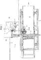
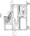
- Figs. 1 and 2 are a plan view and a side view of a right half of a grafted seedling producing device 1 according to an embodiment of the present invention, respectively.
- the grafted seedling producing device 1 is configured in a substantially symmetric manner with respect to a grafting robot main unit 1a that performs a grafting of a scion and a stock by symmetrically arranging, at both sides of the grafting robot main unit 1a ( Fig.
- left and right loading units 2 and 2 that respectively loads grafting seedlings
- left and right pre-processing units 3 and 3 that respectively pre-processes the grafting seedlings received from the loading units 2 and 2
- a joining processing unit 7 that receives a scion and a stock that are pre-processed and joins the scion and stock
- a grafted seedling delivery unit 8 that delivers a grafted seedling obtained by joining the scion and the stock toward a front side of a machine body.
- left and right relay units 9 and 9 for temporarily storing seedlings W for grafting are arranged to deliver the seedlings W respectively between the left and right loading units 2 and 2 and the left and right pre-processing units 3 and 3.
- the loading unit 2 includes a conveying mechanism 11 that sequentially conveys a scion seedling W to the front side, a holding arm 12 that holds and fetches the scion seedling W on the conveying mechanism 11 in a separate manner, and a lateral conveying mechanism 13 that supports the holding arm 12 in a movable manner in the lateral direction.
- the conveying mechanism 11 is configured with a belt conveyer or the like that makes a conveying operation along the lateral direction of the grafting robot main unit 1a, and conveys the scion seedling W to a predetermined position by conveying a cell tray in which a plurality of scion seedlings W grown in a seedling pot until a cotyledon sprouts in a dicotyledonous shape are arranged in a lattice shape by an arrangement pitch.
- the holding arm 12 is configured to cut a root side of an embryonic stem of the scion seedling W while holding it on the conveying mechanism 11 in a separate manner, holds the scion seedling W in a state of having a space for accommodating it in a rotatable manner with the embryonic stem in a standing position, and moves back and forth via a back-and-forth moving mechanism 12b to handle the scion seedling W with the conveying mechanism 11 or the relay unit 9.
- the lateral conveying mechanism 13 is constituted by a linear slider or the like that can control a lateral position of the holding arm 12 in a range until a position of reaching the front of the relay unit 9 by traversing the conveying mechanism 11.
- the lateral conveying mechanism 13 makes the holding arm 12 serve as a transversal conveying holding arm that supplies the seedling to the grafting robot main unit 1a.
- the relay unit 9 includes a supply arm 9a that is a switchable holding mechanism that pinches the scion seedling W received from the holding arm 12 in an opening and closing manner and a cotyledon aligning member 16 that aligns a sprouting axial line direction of cotyledons L and L when receiving the scion seedling W from the holding arm 12.
- the cotyledon aligning member 16 is configured in such a manner that its mounting position can be selected in the relay unit 9, with an aligning unit including a longitudinal direction aligning unit 17 and a lateral direction aligning unit 18 for aligning the sprouting axial line direction of the cotyledons L and L of a seedling received from the holding arm 12 at a predetermined angle.
- the cotyledon aligning member 16 is configured to be fixed to the relay unit 9 with a first mounting screw 16a at a position selected from two mounting positions having an angle difference of 90 degrees in a planar view, forming the longitudinal direction aligning unit 17 that aligns the sprouting axial line direction of the cotyledons in the longitudinal direction of the relay unit 9 and the lateral direction aligning unit 18 that aligns the sprouting axial line direction of the cotyledons in the lateral direction of the relay unit 9, corresponding to the mounting position of the cotyledon aligning member 16, at back and front positions of the cotyledon aligning member 16.
- the longitudinal direction aligning unit 17 is a plate-shaped member elongated in the longitudinal direction of the relay unit 9 from an inclined portion 17a located apart from the cotyledon aligning member 16 toward the front side of the relay unit 9 to a side portion of the relay unit 9, which aligns the sprouting axial line direction of the cotyledons L and L in the longitudinal direction of the relay unit 9 by bringing side edges of the cotyledons L and L into contact with the longitudinal direction aligning unit 17 using the inclined portion 17a as a guide when the relay unit 9 receives the scion seedling from the holding arm 12 in the front.
- the longitudinal direction aligning unit 17 can support scion seedlings having different cotyledon sizes by adjusting a distance from an embryonic stem A.
- the lateral direction aligning unit 18 is a plate-shaped member extending in the lateral direction of the relay unit 9, being configured with a lateral inclined portion 18a with a center portion projected, which aligns the sprouting axial line direction of the cotyledons L and L in the lateral direction of the relay unit 9 by bringing front edges of the cotyledons L and L into contact with the lateral direction aligning unit 18 using the lateral inclined portion 18a as a guide when the relay unit 9 receives the scion seedling from the holding arm 12 in the front.
- the cotyledon aligning member 16 having the above configuration is mounted longitudinally on a side position of the relay unit 9 to use the longitudinal direction aligning unit 17, so that it is possible to align the sprouting axial line direction in the front direction of the relay unit 9 by bringing the side edge of the cotyledon L into contact with the longitudinal direction aligning unit 17 using the inclined portion 17a as a guide when the relay unit 9 receives the scion seedling from the holding arm 12 in the front.
- the longitudinal direction aligning unit 17 is applied to a grafting process in which a relation between sprouting axial lines of the scion and the stock shows an angle difference of 90 degrees, which means that, for a seedling having a cross-sectional shape of its embryonic stem close to a rectangular shape or a circular shape, such as a cucumber seedling and a melon seedling, it is possible to produce a grafted seedling with which each of the cotyledons can be exposed to the sunlight by setting the cotyledon sprouting axial line directions with an angle difference of 90 degrees.
- the cotyledon aligning member 16 is mounted at a transversal position of the relay unit 9 to use the lateral direction aligning unit 18, so that it is possible to align the sprouting axial line direction in the lateral direction of the relay unit 9 by bringing the front edges of the cotyledons L and L into contact with the lateral direction aligning unit 18 using the lateral inclined portion 18a as a guide when the relay unit 9 receives the scion seedling from the holding arm 12 in the front.
- the lateral direction aligning unit 18 is applied to a grafting process in which the sprouting axial lines of the scion and the stock match each other, which means that, for a seedling having a cross-sectional shape of its embryonic stem close to an elliptical shape, such as a watermelon seedling, it is possible to produce a grafted seedling with which a joining area of the scion and the stock can be maximized by matching the cotyledon sprouting axial line directions.
- either one of the two aligning units, the longitudinal direction aligning unit 17 and the lateral direction aligning unit 18, is selected by switching the mounting position of the cotyledon aligning member 16, so that the cotyledon sprouting axial line direction of the scion or the stock can be switched. Therefore, with the grafted seedling producing device 1, it is possible to effectively perform the grafting process in a general manner by switching the sprouting axial line direction to be aligned for various seedlings having a cotyledon that sprouts in a dicotyledonous shape by a simple configuration using a cotyledon aligning member of which the mounting position can be selected.
- a cotyledon aligning member 21 of another example is configured to be fixed to the relay unit 9 with a second mounting screw (not shown) at a position selected from two mounting positions having an angle difference of 90 degrees in a planar view, forming a longitudinal direction aligning unit 22 of the another example that aligns the sprouting axial line directions of the cotyledons in the longitudinal direction of the relay unit 9 and a lateral direction aligning unit 23 of the another example that aligns the sprouting axial line directions of the cotyledons in the lateral direction of the relay unit 9, corresponding to the mounting position of the cotyledon aligning member 21, at back and front positions of the cotyledon aligning member 21.
- the longitudinal direction aligning unit 22 of the another example is a plate-shaped member elongated along a side portion of the relay unit 9 with a second roller 22a located apart from the cotyledon aligning member 21 toward the front side of the relay unit 9, which aligns the cotyledon sprouting axial line direction in the longitudinal direction of the relay unit 9 by bringing a side edge of the cotyledon L into contact with the longitudinal direction aligning unit 22 using the second roller 22a as a guide when the relay unit 9 receives the scion seedling from the holding arm 12 in the front.
- the longitudinal direction aligning unit 22 can support scion seedlings having different cotyledon sizes by adjusting a contact position of the cotyledon.
- the lateral direction aligning unit 23 of the another example a plate-shaped member extending in the lateral direction of the relay unit 9 with a center portion projected, which aligns the sprouting axial line directions of the cotyledons L and L in the lateral direction of the relay unit 9 by bringing front edges of the cotyledons L and L into contact with the lateral direction aligning unit 23 using a lateral inclined portion as a guide when the relay unit 9 receives the scion seedling from the holding arm 12 in the front.
- the lateral direction aligning unit 23 can support scion seedlings having different cotyledon sizes by adjusting a contact position of the cotyledon.
- the cotyledon aligning member 21 of the another example is mounted longitudinally on a side position of the relay unit 9 to use the longitudinal direction aligning unit 22 of the another example, and a longitudinal aligning member 14, which will be described later, formed with a plate-shaped member elongated in the longitudinal direction along the holding arm 12 is fixed to be used as a stopper in the longitudinal direction.
- a first roller 14a is provided on a distal end position of the longitudinal aligning member 14 to guide the cotyledon.
- the relay unit 9 When the relay unit 9 receives the scion seedling from the holding arm 12 in the front by moving forward the holding arm 12, the sprouting axial line directions of the cotyledons L and L are guided in the longitudinal direction by the longitudinal aligning member 14 that is fixed at a side position of the holding arm 12 as a stopper, and by bringing side edges of the cotyledons L and L into contact with the longitudinal direction aligning unit 22 of the another example using the second roller 22a of the relay unit 9 as a guide, it is possible to align the sprouting axial line direction in the front direction of the relay unit 9.
- the cotyledon aligning member 21 is mounted at a transversal position of the relay unit 9 to use the lateral direction aligning unit 23 of the another example, so that it is possible to align the sprouting axial line direction in the lateral direction of the relay unit 9 by bringing the front edges of the cotyledons L and L into contact with the lateral direction aligning unit 23 using the lateral inclined portion as a guide when the relay unit 9 receives the scion seedling from the holding arm 12 in the front.
- either one of the two aligning units, the longitudinal direction aligning unit 22 of the another example and the lateral direction aligning unit 23 of the another example is selected by switching the mounting position of the cotyledon aligning member 21 of the another example, in the same manner as the cotyledon aligning member 16, so that the cotyledon sprouting axial line direction of the scion or the stock can be switched.
- the grafted seedling producing device 1 it is possible to effectively perform the grafting process in a general manner by switching the sprouting axial line direction to be aligned for various seedlings having a cotyledon that sprouts in a dicotyledonous shape by a simple configuration using a cotyledon aligning member of which the mounting position can be selected.
- an intermediate aligning unit is installed to perform pre-processing to align the cotyledon in the longitudinal direction prior to the alignment of the cotyledon in the relay unit 9.
- an intermediate aligning unit 31 is provided at a lateral conveying end position of the holding arm 12.
- the intermediate aligning unit 31 is a plate-shaped member elongated in a lateral direction viewed from the lateral conveying direction of the holding arm 12 with an intermediate inclined portion 31a with a center portion projected, which is formed in the same manner as the lateral direction aligning unit 18, and aligns the sprouting axial line directions of the cotyledons L and L in the lateral direction of the intermediate aligning unit 31, that is, in the longitudinal direction of the relay unit 9, by bringing front edges of the cotyledons L and L into contact with the intermediate aligning unit 31 using the intermediate inclined portion 31a as a guide when the intermediate aligning unit 31 receives the scion seedling from the holding arm 12 in the front.
- the cotyledon aligning method for the scion seedling W using the intermediate aligning unit 31 includes fixing the longitudinal direction aligning unit 22 for preliminary alignment that aligns the cotyledons L and L in the longitudinal direction at the side position of the holding arm 12, performing a lateral movement P1 to the intermediate aligning unit 31 at the lateral conveying end position at the maximum speed by the lateral conveying mechanism 13 while the holding arm 12 separately holds the scion seedling W on the conveying mechanism 11 after mounting the cotyledon aligning member 16 on the relay unit 9 such that the longitudinal direction aligning unit 17 is to be used, performing a lateral movement P2 to return to the front position of the relay unit 9, and performing a longitudinal movement P3 for moving the holding arm 12 to the relay unit 9 by the back-and-forth moving mechanism 12b.
- the lateral conveying mechanism 13 is configured to control the movement speed to low right before the intermediate aligning unit 31, and the intermediate aligning unit 31 is configured to be hoistable down to a standby position when it is not used.
- the longitudinal aligning member 14 and the longitudinal direction aligning unit 22 of the another example are arranged as two guide plates to align the cotyledons L and L in the longitudinal direction in the relay unit 9, and a swing conveying operation of the holding arm 12 is performed in a state in which the first roller 14a and the second roller 22a come close to each other, that is, the scion seedling in the holding arm 12 is delivered to the relay unit 9 by performing a forward movement P11 and a backward movement P12 and then a forward movement P13 of the holding arm 12 again.
- an alignment is performed by conveying a seedling by the lateral conveying mechanism 13 to an alignment plate installed at a conveying direction end point passing a position of the relay unit 9 after fetching the seedling, so that a conveying distance is long because the seedling is to be returned to the position of the relay unit 9, causing a startup loss time due to an increase of the number of conveyances, the processing speed is slow, and different programs are required for a watermelon and a cucumber having different alignment directions.
- the above swing alignment it is possible to cut down the cost from enhancement of the processing speed, generalization of the program, and reduction of the lateral conveyance strokes.
- a seedling is fetched by the holding arm 12 from a seedling raising tray by setting a pullout lever 12u, and a control of direction and height of a leaf is performed by the longitudinal aligning member 14 and the first roller 14a mounted at a higher position on the side of the holding arm 12.
- the start state and the end state of the fetching operation are shown in Figs. 10A and 10B , respectively.
- the longitudinal aligning member 14 serves as a stopper for positioning rotating cotyledons L and L at stop positions, and the preliminary alignment of the cotyledons L and L of the scion seedling W is performed by arranging the first roller 14a at a position where the cotyledon L bumps when the seedling is pulled back by the holding arm 12 at the front position.
- an alignment of a scion of a cucumber or a melon is performed by using a method by a contact with a linear actuator of the lateral conveying mechanism 13, in which there is no swinging process for the stock and the contact, and the contact is made at a low speed.
- a longitudinal aligning member 14 it is possible to perform a certain level of preliminary alignment to set a direction of the cotyledon.
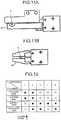
- the supply arm 9a in which a semicircular gap or a circular gap formed by left and right semicircles is formed to hold the seedling in a state of having a space for the embryonic stem to move to adjust a holding height of the seedling and an auxiliary arm 9b that holds the embryonic stem A under the supply arm 9a in a contacting manner are provided, and including the holding arm 12 and a cutting arm 12a under the holding arm 12, the operation is controlled by a first process to a fifth process, as shown in a process chart of a delivery operation in Fig. 12 .
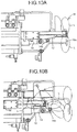
- the scion seedling W held by the holding arm 12 and the cutting arm 12a (the first process) is held by the supply arm 9a and the auxiliary arm 9b of the relay unit 9 (the second process) at the time of delivery, as shown in a plan view and a side view of Figs. 13A and 13B , respectively.
- the seedling is delivered by opening the holding arm 12 and the cutting arm 12a (the third process), as shown in Fig. 14A
- the height of the seedling is positioned by performing opening and closing of the auxiliary arm 9b once (the fourth process), as shown in Fig. 14B
- the operation is controlled to stand by for the next process by holding the seedling with the supply arm 9a and the auxiliary arm 9b again (the fifth process).
- the auxiliary arm 9b is opened, and then opening of the holding arm 12 and closing of the auxiliary arm 9b are synchronized with each other.
- the scion seedling is in a free state in a broad slit of the supply arm 9a at the time of delivering the seedling, so that if the cotyledon is stuck to the holding arm 12, a direction of the aligned cotyledon is changed.
- the scion seedling does not require a severe positioning of the height as the stock seedling, and in actual cases, a positioning process is applied to the stock seedling in which both upper and lower arms are brought into contact with the seedling and the lower arm is pulled down by a cylinder.
- this positioning process cannot be applied to the scion seedling because the scion seedling is narrower and weaker than the stock seedling, so that the positioning of the height of the scion seedling can be performed by the above method.
- a back-and-forth moving operation of the holding arm 12 shown in Figs. 15A and 15B is performed more than usual, for example, three times if the usual case is two times.
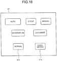
- a switching between the overgrown case and the normal case is performed by a mode select with a "normal" switch 41a and an "overgrown" switch 41b on an operation panel 41 shown in an overview thereof in Fig 16 (it is configured that, if the mode is not selected when pressing a start switch, an input from the start switch is ignored), and before delivering the seedling from the holding arm 12, the back-and-forth moving operation of the holding arm 12 is performed two times in the normal mode and three times in the overgrown mode, for example, according to the selected mode by a back-and-forth movement control process shown in a flowchart of Fig. 17 .
- a pre-aligning unit 51 that aligns the cotyledons L and L in the lateral direction along the conveying direction of the lateral conveying mechanism 13 is provided.
- the pre-aligning unit 51 includes a pre-aligning plate 52 for aligning the seedling in advance and a reverse roller 53.
- a supporting point 53a of the reverse roller 53 is configured with a spring for changing a bump strength (contacting strength) depending on a stiffness of the seedling.
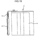
- a relay aligning plate 61 that aligns the cotyledon in the longitudinal direction is provided until a height position of the holding arm 12 in which a synthetic resin rubber 62 is patched on a surface that serves as a guide for the cotyledon. Furthermore, a distal end portion 12c of the holding arm 12 that conveys the seedling, which faces the relay aligning plate 61 is R-shaped, and the synthetic resin rubber 62 is arranged at the height position of the holding arm 12 such that the holding arm 12 is stopped during its opening operation.
- the relay alignment plate 61 having the above configuration does not require a clearance that serves as a space for opening and closing operation at a side of the holding arm 12 according to a conventional configuration, it is possible to improve the precision of aligning the cotyledon by preventing an alignment failure caused by the cotyledon entering into the clearance or a damage to the cotyledon caused when the holding arm performs an operation in the longitudinal direction.
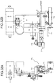
- the grafted seedling processing apparatus includes a grafting processing unit 74 employing a grafting robot that is arranged at the center to perform a joining of a stock seedling and a scion seedling in an automatic manner, left and right loading units 2 and 2 employing conveyors for conveying cell trays of the stock seedling and the scion seedling at left and right sides, respectively, a clip supply unit 74a that supplies a clip for fixing the joined stock seedling and scion seedling from behind the grafting processing unit 74, a grafted seedling delivery unit 4 that delivers a grafted seedling obtained by joining the stock seedling and the scion seedling, extending ahead from the front of the grafting processing unit 74.
- a grafting processing unit 74 employing a grafting robot that is arranged at the center to perform a joining of a stock seedling and a scion seedling in an automatic manner
- left and right loading units 2 and 2 employing conveyors for conveying cell trays of the stock
- the grafting processing unit 74 receives the stock seedling and the scion seedling from lateral conveyance holding arms (not shown) respectively conveying the stock seedling and the scion seedling in the cell trays from the left and right loading units in a transversal manner.
- the grafting processing unit 74 cuts the stock seedling and the scion seedling and joins them to obtain a grafted seedling, and fixes the grafted seedling with a clip received from the clip supply unit 74a.
- the grafted seedling obtained in this manner is then delivered from the grafted seedling delivery unit 4.
- the grafting processing unit 74 has a stock handling unit on its left half side and a scion handling unit on its right half side, including left and right seedling supply bases 11L and 11R at left and right side end portions, which receive and hold a stock seedling and a scion seedling from the loading units 2 and 2 via a transversal conveying mechanism (not shown), respectively, a joining unit 75 that joins and fixes the stock and the scion at the center position with a clip received from the clip supply unit 74a on the rear side, rotary conveying units 73L and 73R that respectively serve as left and right seedling holding devices using left and right rotary arms that rotate to convey the seedlings each including a conveying arm 73a for pinching the seedling from each of the seedling supply bases 11L and 11R to the
- a roller arm 77 for pressing the cotyledon is provided above the left cutting unit 76L for the stock.
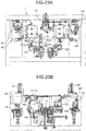
- Reference numerals 18L and 18R indicate second aligning plates
- reference numerals 19L and 19R indicate hoist cylinders
- reference numeral 20 indicates a root cutting device.
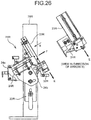
- the left and right cutting units 76L and 76R respectively include cutter bases 22L and 22R respectively mounted on two supporting pillars 78L and 78R that are standing at left and right sides, cutter units 23L and 23R each performing a cutting operation in a predetermined cutter trajectory, and slide supporting units 24L and 24R that respectively perform back-and-forth moving operations of the cutter units 23L and 23R for every cutting operation.
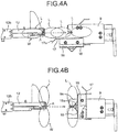
- the cutter unit 23L for the stock includes a blade 31L in a razor shape arranged at its end, which performs a cutting operation in a cutter trajectory C for the stock in a straight line inclined toward the rotary conveying unit 73L for the stock at the back side and a pressing member 32L for the stock, which presses a cutting target at an advance position where the cutter unit 23L is advanced by the slide supporting unit 24L that serves as a supporting unit for the stock to perform the cutting operation.
- the pressing member 32L is arranged at a position ahead of a cutting portion of the cutting target that is held by the rotary conveying unit 73L, that is, a position to press and fix a portion exceeding a crossing portion of the cutter trajectory.
- the slide supporting unit 24L is configured with a height adjusting unit 24a and an angle adjusting unit 24b to adjust a height position and an advance direction D of the cutter unit 23L.
- the roller arm 77 is configured to interlock and rotate by a rotary actuator to press the cotyledon with a sponge roller 77a from above corresponding in response to a cutting operation of the cutter unit 23L.
- a leaf blowing guide 33 of a leaf spring shape to receive an unnecessary leaf that is cut and to blow the unnecessary leaf in a predetermined direction and a transparent cover 34 to protect a cylinder near a point of fall of the leaf are provided on an opposite side to the cutting target across the blade 31L, to prevent the leaf from entering into the cylinder and to have a visual contact with an operation of the cylinder.
- the leaf blowing guide 33 is more inclined than the cutting trajectory of the blade 31L from the embryonic stem of the seedling, and discharges the unnecessary leaf from the cutting trajectory obliquely downward on the opposite side to the leaf blowing guide 33 by receiving a part of unnecessary leaves moving in a cutting direction (an upper direction) by the cutting.
- the cutter unit 23R for the scion includes a blade 31R in a razor shape arranged at its end, which performs a cutting operation in a cutter trajectory E for the scion in a straight line inclined toward the rotary conveying unit 73R for the scion at the back side and a pressing member 32R for the scion, which presses a cutting target at an advanced position where the cutter unit 23R is advanced by the slide supporting unit 24R that serves as a supporting unit for the scion to perform the cutting operation.
- the pressing member 32R is arranged at a position ahead of a cutting portion of the cutting target that is held by the rotary conveying unit 73R, that is, a position to press and fix a portion exceeding a crossing portion of the cutter trajectory.
- the slide supporting unit 24R is configured with a height adjusting unit 24a and an angle adjusting unit 24b to adjust a height position and an advance direction F of the cutter unit 23R.
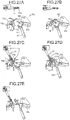
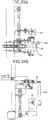
- FIG. 27A A cutting operation of each of the left and right cutting units 76L and 76R is explained in detail.
- the rotary conveying unit 73L is positioned to make the seedling in the conveying arm 73a reach the cutter unit 23L at a retracted position, at a step 2 ( Fig. 27B ), the cutter unit 23L is advanced to an advance position by the slide supporting unit 24L so that the pressing member 32L is positioned at a portion ahead of the cutting position, at a step 3 ( Fig.
- the cotyledon is pressed against an embryonic stem receiving portion 73b by a rotation of the sponge roller 77a of the roller arm 77, at a step 4 ( Fig. 27D ), the blade 31L of the cutter unit 23L cuts the crossing portion of the cutter trajectory of the embryonic stem, and at a step 5 ( Fig. 27E ), the cutter unit 23L is retracted by the slide supporting unit 24L, by which the cutting operation is completed.
- the rotary conveying unit 73R is positioned to make the seedling in the conveying arm 73a reach the cutter unit 23R at a retracted position
- the cutter unit 23R is advanced to an advance position by the slide supporting unit 24R so that the pressing member 32R is positioned at a portion ahead of the cutting position
- the blade 31R of the cutter unit 23R cuts the crossing portion of the cutter trajectory of the embryonic stem
- the cutter unit 23R is retracted by the slide supporting unit 24R, by which the cutting operation is completed.
- the cutter units 23L and 23R can be advanced and retracted via the slide supporting units 24L and 24R, respectively, and by performing cutting operations of the predetermined cutting trajectories C and E at the advance positions, respectively, cuts portions where the embryonic stems cross the cutter trajectories for the seedlings pinched by the rotary conveying units 73L and 73R reaching the cutter units 23L and 23R, respectively.
- the pressing members 32L and 32R are advanced by the advance operations of the cutter units 23L and 23R, and by the pressing members 32L and 32R pressing the portions ahead of the cutting positions of the seedlings pinched by the rotary conveying units 73L and 73R against the holding sides, the cutting targets are positions and cut.
- the cutting device for the grafted seedling processing because the portions ahead of the cutting positions of the embryonic stems of the seedlings held by the seedling holding device composed of the rotary conveying units 73L and 73R are positioned by the pressing members 32L and 32R, respectively, and the blades 31L and 31R of the cutter units perform the cutting operations for cutting the embryonic stem S between the seedling holding device and the pressing portion, it is possible to form cutting planes with a high precision along the cutting trajectories C and E.
- a weight 35a on a shutter 35 that moves when opening and closing the arm, it is possible to adjust the shutter 35 to the seedling according to a size of the cotyledon of the seedling by making the shutter 35 rotate around an upper supporting point against a gravitational force of the weight 35a when aligning the seedling by correcting a direction of the cotyledon by bringing the cotyledon into contact with the shutter 35.
- the shutter 35 When there is no seedling supplied or when it is not necessary to rotate the shutter 35 because the cotyledon is too small, the shutter 35 is returned to a desired setting position by the weight 35a.
- the weight of the weight 35a can be adjusted by removing or changing the weight 35a depending on the strength or type of the seedling.
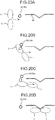
- the direction of the cotyledon is aligned between an aligning plate 42 provided on the seedling supply base 11R and a second aligning plate 18R provided in a grafting device that performs an up-and-down operation (see Figs. 23A and 23B ) for the watermelon, and the direction of the cotyledon is aligned by a contact of the aligning plate 42 of the seedling supply base 11R with an R portion, where its switching can be set on an operation panel.
- the direction of the cotyledon is preliminarily corrected to face the lateral direction by making the cotyledon of the seedling have a contact with the second aligning plate 18R at an end of the lateral movement of the transversal conveyance holding arm, and the direction of the cotyledon of the seedling is aligned by a plurality of times of contacts of the cotyledon with the aligning plate 42 with a longitudinal back-and-forth movement of the holding arm after that.
- a seeding is performed in advance in such a manner that the cotyledon of the seedling faces a longitudinal direction of a cell tray. Because a raised seedling substantially faces the longitudinal direction of the cell tray, the direction of the cotyledon of the seedling is aligned by hoisting up the second aligning plate 18R by an operation of the hoist cylinder (see Figs. 23A and 23B. Fig.
- the second aligning plate 18R can be switched between an operation position and a retracted position by operating the hoist cylinder 19R on an operation panel.
- the seedling As for a swinging operation in a postural control when delivering the seedling to the seedling supply base, the seedling is subject to the postural control focusing on a height direction for the scion and a direction of the cotyledon for the stock. Therefore, because the number of necessary swings is different for each of the left and right seedling supply bases 11L and 11R, the number of swings can be set separately on the operation panel.
- the configuration can be taken such that a tolerance of the direction of the cotyledon of the seedling is decreased by the seedling moving downward (the height control is performed) as a repetition of the swing operation.
- the cotyledon of the seedling can be aligned to a desired direction gradually with the repetition of the swing operation, so that it is possible to prevent the seedling from being damaged by a sudden change of the direction of the cotyledon of the seedling at the aligning plate.
- the seedling supply base 11R for the scion seedling is configured with a supply arm 36 and an auxiliary arm 37, so that after the swing operation of the transversal conveyance holding arm, the supply arm 36 and the auxiliary arm 37 hold the seedling supplied to the seedling supply base 11R from the transversal conveyance holding arm, and in order to convey the seedling by the rotary conveying unit 73R, the holding of the supply arm 36 and the auxiliary arm 37 is released at the time when the rotary conveying unit 73R starts to be stretched to hold the seedling. Therefore, because the posture of the seedling becomes improper from the release of the supply arm 36 and the auxiliary arm 37 until the holding arm of the rotary conveying unit 73R holds the seedling, there is a possibility that the position of the embryonic stem becomes misaligned.
- a scion seedling guide 38 to control the posture of the seedling is provided, such that the position of the embryonic stem is kept aligned when the holding arm of the rotary conveying unit 73R receives the seedling (the auxiliary arm 37 is opened to deliver the seedling).
- the scion seedling guide 38 becomes in an active state when the rotary conveying unit 73R faces the seedling supply base 11R before the arm holds the seedling, in an inactive state when the rotary conveying unit 73R completely moves away from the seedling supply base 11R portion after holding the seedling, so that the scion seedling guide 38 becomes active from the opposite side to the rotary conveying unit 73R on the seedling without affecting the conveyance of the seedling by the rotary conveying unit 73R and becomes inactive when the seedling is supplied from the transversal conveyance holding arm to the seedling supply base 11R without affecting the supply of the seedling.
- the seedling supply base 11L for the stock seedling includes a pair of pull-down arms 39 and a pull-down mechanism for aligning the height of the seedling by engaging a cylinder 63 with a plate 40.
- a speed of pulling down and a resistance applied to the seedling at the time of pull-down are kept constant by providing a pull-down guide 64 on the opposite side to the cylinder 63 in proximity across the stock seedling.
- the cylinder 63 is provided on the clip supply unit 74a side in opposite to the stock seedling supplied to the seedling supply base 11L, it is possible to avoid an interruption with the transversal conveyance holding arm that supplies the seedling to the seedling supply base 11L by moving from the other side.
- the rotary conveying unit 73L includes a seedling guide 72 that can be stretched and retracted by a cylinder 72a down the conveying arm 73a.
- the seedling guide 72 serves as a positioning guide for the seedling by having a contact with the embryonic stem of the seedling when receiving the seedling from the seedling supply base 11L in a stretched state, a member for preventing bending of the embryonic stem of the seedling and a position misalignment when cutting the seedling in a state of having a contact with the embryonic stem, and a bumping plate for preventing the embryonic stem of the seedling from separating when cutting the root.
- the seedling guide 72 becomes in a retracted state when joining the seedlings and moves away from the seedling.
- the joining unit 75 includes a guide 82 for correction and prevention (on the opposite side to the root cutting device 20 for the stock seedling (see Figs. 23A and 23B )) provided from the scion side that becomes a reference for a joining center.
- the guide 82 can be operated via a pressing plate 82a that receives a rotation of a rotary actuator 81.
- the guide 82 is brought into contact with a distal end of a supplied clip, so that a correction guide is formed, which corrects and prevents a position misalignment of the seedling and the clip when applying the clip on the seedlings.
- the present invention has the following effects.
- the stock cutter unit performs a cutting operation by a predetermined stock cutter trajectory
- the embryonic stem of the stock seedling is cut at a portion that crosses the stock cutter trajectory by pinching and holding the seedling with the stock seedling holding unit reaching the stock cutter unit
- the stock cutter unit can move back and forth via the supporting unit for the stock and presses a portion ahead of the cutting position of the embryonic stem extending from the stock seedling holding unit by the stock pressing member at the advance position, to position the seedling by pressing the embryonic stem against the stock seedling holding unit side.
- the portion ahead of the cutting position of the embryonic stem of the stock seedling held by the stock seedling holding unit is positioned by the stock pressing member with an advance operation of the stock cutter unit, and the stock cutter unit performs the cutting operation on the embryonic stem between the stock seedling holding unit and the pressing portion of the stock, it is possible to form a highly precise cutting plane along the stock cutter trajectory.
- the cutting planes can be matched in an accurate manner when joining the stock and the scion, it is possible to increase the proportion of grafted seedlings with satisfactory joining by preventing a joining failure of the grafted seedling.
- the scion cutter unit performs a cutting operation by a predetermined scion cutter trajectory
- the embryonic stem of the scion seedling is cut at a portion that crosses the scion cutter trajectory by pinching and holding the seedling with the scion seedling holding unit reaching the scion cutter unit
- the scion cutter unit can move back and forth via the supporting unit for the scion and presses a portion ahead of the cutting position of the embryonic stem extending from the scion seedling holding unit by the scion pressing member at the advance position, to position the seedling by pressing the embryonic stem against the scion seedling holding unit side.
- the portion ahead of the cutting position of the embryonic stem of the scion seedling held by the scion seedling holding unit is positioned by the scion pressing member with an advance operation of the scion cutter unit, and the scion cutter unit performs the cutting operation on the embryonic stem between the scion seedling holding unit and the pressing portion of the scion, it is possible to form a highly precise cutting plane along the scion cutter trajectory.
- the cutting planes can be matched in an accurate manner when joining the stock and the scion, it is possible to increase the proportion of grafted seedlings with satisfactory joining by preventing a joining failure of the grafted seedling.
- the correction and prevention guide can correct and prevent a position misalignment of the seedling and the clip by having a contact with a distal end of the clip supplied from the clip supply unit, it is possible to increase the proportion of grafted seedlings with satisfactory joining by further preventing a joining failure of the grafted seedling.
- the scion seedling and the stock seedling can be supplied to the main unit after correcting the direction of the cotyledon of the seedling by the shutter. Furthermore, it is possible to adjust the shutter to the seedling according to a size of the cotyledon of the seedling by making the shutter rotate around an upper supporting point against a gravitational force of the weight. In addition, when there is no seedling supplied or when it is not necessary to rotate the shutter 35 because the cotyledon is too small, it is possible to return the shutter to a desired setting position by the weight. Therefore, it is possible to increase the proportion of grafted seedlings with satisfactory joining by further preventing a joining failure of the grafted seedling.
- the direction of the cotyledon is preliminarily corrected by making the cotyledon of the seedling have a contact with the second aligning plate, and the direction of the cotyledon of the seedling is aligned by a contact of the cotyledon with the aligning plate with a movement of the holding arm after that.
- a tolerance of the direction of the cotyledon of the seedling is decreased by the seedling moving downward as a repetition of the swing operation when aligning the direction of the cotyledon of the seedling, and it is possible to align the cotyledon of the seedling to a desired direction gradually with the repetition of the swing operation, so that it is possible to prevent the seedling from being damaged by a sudden change of the direction of the cotyledon of the seedling at the aligning plate. Therefore, it is possible to increase the proportion of grafted seedlings with satisfactory joining by further preventing a joining failure of the grafted seedling.
- the scion seedling guide becomes active from the opposite side to the scion seedling holding unit on the scion seedling without affecting the conveyance of the seedling by the scion seedling holding unit and becomes inactive when the scion seedling is supplied to the scion seedling supply base without affecting the supply of the seedling, it is possible to prevent the position of the embryonic stem from being misaligned from an improper posture of the seedling from the release of the supply arm and the auxiliary arm until the holding arm of the scion seedling holding unit holds the seedling. Therefore, it is possible to increase the proportion of grafted seedlings with satisfactory joining by further preventing a joining failure of the grafted seedling.
- the seedling guide can serve as a positioning guide for the seedling by having a contact with the embryonic stem of the stock seedling when receiving the stock seedling from the stock seedling supply base in a stretched state, a member for preventing bending of the embryonic stem of the seedling and a position misalignment when cutting the seedling in a state of having a contact with the embryonic stem, and a bumping plate for preventing the embryonic stem of the seedling from separating when cutting the root, and to become in a retracted state when joining the seedlings and move away from the seedling. Therefore, it is possible to increase the proportion of grafted seedlings with satisfactory joining by further preventing a joining failure of the grafted seedling.
Landscapes
- Life Sciences & Earth Sciences (AREA)
- Botany (AREA)
- Developmental Biology & Embryology (AREA)
- Environmental Sciences (AREA)
- Cultivation Of Plants (AREA)
- Transplanting Machines (AREA)
- Cultivation Receptacles Or Flower-Pots, Or Pots For Seedlings (AREA)
- Lining Or Joining Of Plastics Or The Like (AREA)
Claims (10)
- Gepfropfte Sämling-Erzeugungsvorrichtung, die Folgendes umfasst:eine Unterlagesämling-Halteeinheit (73L), die einen Unterlagesämling hält und befördert;eine Unterlage-Schneideeinheit (76L), die den von der Unterlagesämling-Halteeinheit (73L) gehaltenen Unterlagesämling schneidet; undeine Verbindungseinheit (75), die den von der Unterlagesämling-Halteeinheit (73L) beförderten Unterlagesämling und einen Pfropfreissämling verbindet; wobeidie Unterlage-Schneideeinheit (76L) eine Unterlage-Messereinheit (23L) enthält, die eine Unterlageklinge (31L) zum Schneiden des Unterlagesämlings mit einer vorbestimmten Unterlagemesserbahn (C) enthält, die Unterlagesämling-Halteeinheit (73L) einen embryonalen Stamm (S) eines Sämlings zum Aufpfropfen an einer vorbestimmten Position auf der Unterlagemesserbahn (C) in einer vertikalen Stellung hält, dadurch gekennzeichnet, dass die Unterlage-Schneideeinheit (76L) ferner Folgendes enthält:eine Trageinheit (24L), die konfiguriert ist, die Unterlage-Messereinheit (23L) zum Schneiden in der Nähe der Unterlagesämling-Halteeinheit (73L) von einer eingefahrenen Position zu einer ausgefahrenen Position auszufahren, undein Unterlageanpresselement (32L), das in der ausgefahrenen Position einen Abschnitt, der sich vor einer Abschneideposition des embryonalen Stamms (S) befindet, von einer Sämling-Halteposition gegen die Seite der Unterlagesämling-Halteeinheit (73L) anpresst und befestigt.
- Gepfropfte Sämling-Erzeugungsvorrichtung nach Anspruch 1, wobei die gepfropfte Sämling-Erzeugungsvorrichtung ferner Folgendes enthält:eine Pfropfreissämling-Halteeinheit (73R), die einen Pfropfreissämling hält und befördert, undeine Pfropfreis-Schneideeinheit (76R), die den von der Pfropfreissämling-Halteeinheit (73R) gehaltenen Pfropfreissämling schneidet,wobei die Verbindungseinheit (75) den von der Pfropfreissämling-Halteeinheit (73R) beförderten Pfropfreissämling und den Unterlagesämling verbindet, die Pfropfreis-Schneideeinheit (76R) eine Pfropfreis-Messereinheit (23R) enthält, die eine Pfropfreis-Klinge (31R) zum Schneiden des Pfropfreissämlings mit einer vorbestimmten Pfropfreismesserbahn (E) enthält, die Pfropfreissämling-Halteeinheit (73R) einen embryonischen Stamm (S) eines Sämlings zum Aufpfropfen an einer vorbestimmten Position auf der Pfropfreismesserbahn (E) in einer vertikalen Stellung hält, wobei die Pfropfreis-Schneideeinheit (76R) Folgendes enthält:eine Trageinheit (24R), die konfiguriert ist, die Pfropfreis-Messereinheit (23R) zum Schneiden in der Nähe der Pfropfreissämling-Halteeinheit (73R) von einer eingefahrenen Position zu einer ausgefahrenen Position auszufahren, undein Pfropfreis-Anpresselement (32R), das in der ausgefahrenen Position einen Abschnitt, der sich vor einer Abschneideposition des embryonalen Stamms (S) befindet, von einer Sämling-Halteposition gegen die Seite der Pfropfreissämling-Halteeinheit (73R) anpresst und befestigt, wobeisowohl die Unterlage-Schneideeinheit (76L) als auch die Pfropfreis-Schneideeinheit (76R) konfiguriert sind, den embryonischen Stamm (S) an einem Abschnitt in der Nähe der Sämlinghalteposition abzuschneiden,die Unterlageklinge (31L) in der Unterlage-Schneideeinheit (76L) den embryonischen Stamm (S) mit einer Aufwärtsbewegung auf der Unterlagemesserbahn (C) in einer geneigten geraden Linienform abschneidet, unddie Pfropfreisklinge (31R) in der Pfropfreis-Schneideeinheit (76R) den embryonischen Stamm (S) mit einer Abwärtsbewegung auf der Pfropfreismesserbahn (E) in einer geneigten geraden Linienform abschneidet.
- Gepfropfte Sämling-Erzeugungsvorrichtung nach Anspruch 1 oder 2, wobei
die Unterlagesämling-Halteeinheit (73L) einen Arm (77) enthält, der ein Keimblatt von oben auf einen embryonischen Stamm-Aufnahmeabschnitt (73b) presst, und
eine Blattblasführung (33), die ein überflüssiges Blatt, das von der Unterlageklinge (31L) der Unterlage-Schneideeinheit (76L) abgeschnitten worden ist, aufnimmt und wegbläst. - Gepfropfte Sämling-Erzeugungsvorrichtung nach einem der Ansprüche 1 bis 3,
wobei die Verbindungseinheit (75) konfiguriert ist, den Unterlagesämling und den Pfropfreissämling mit einer Klammer, die von einer Klammerzuführeinheit (74a) zugeführt wird, zu verbinden, und
die Verbindungseinheit (75) eine Korrektur- und Verhinderungsführung (82) enthält, die einen Vorgang des Korrigierens und Verhinderns eines Positionsversatzes des Sämlings und der Klammer durchführt, indem sie sich im Kontakt mit einem distalen Ende der von der Klammerzuführeinheit (74a) zugeführten Klammer befindet. - Gepfropfte Sämling-Erzeugungsvorrichtung nach einem der Ansprüche 1 bis 4, die ferner eine Ladeeinheit (2) zum Laden des Unterlagesämlings oder eine Ladeeinheit (2) zum Laden des Pfropfreissämlings umfasst, wobei
die Ladeeinheit Folgendes enthält:einen Beförderungsmechanismus (11), der eine Aussaatplatte, in der mehrere Sämlinge (W) durch eine Anordnungsteilung sequentiell angeordnet sind, befördert,einen Haltearm (12), der einen von dem Beförderungsmechanismus (11) beförderten Sämling (W) holt, undeinen seitlichen Beförderungsmechanismus (13), der den Haltearm (12) bewegt, wobeider Haltearm (12) einen embryonischen Stamm des Sämlings derart hält, dass er einen Raum aufweist, um diesen drehbar aufzunehmen,der seitliche Beförderungsmechanismus (13) konfiguriert ist, den von dem Haltearm (12) gehaltenen Sämling (W) zum Pfropfen des Pfropfreissämlings und des Unterlagesämlings einer Haupteinheit (1a) zuzuführen,die gepfropfte Sämling-Erzeugungsvorrichtung ferner Folgendes umfasst:einen Zuführarm (9a), der den Sämling von dem Haltearm (12) aufnimmt; undeine Verschlussblende (35), die eine Richtung eines Keimblatts des Sämlings mit einem Schwingvorgang des Haltearms (12) korrigiert, wenn der Zuführarm (9a) den Sämling aufnimmt, unddie Verschlussblende (35) ein Gewicht (35a) enthält und konfiguriert ist, sich um einen oberen Tragpunkt zu drehen, der an einer Position vorgesehen ist, an der die Verschlussblende (35) durch Öffnen und Schließen des Haltearms (12) bewegt wird. - Gepfropfte Sämling-Erzeugungsvorrichtung nach einem der Ansprüche 1 bis 4, die ferner eine Ladeeinheit (2) zum Laden des Unterlagesämlings oder eine Ladeeinheit (2) zum Laden des Pfropfreissämlings umfasst, wobei
die Ladeeinheit Folgendes enthält:einen Beförderungsmechanismus (11), der eine Aussaatplatte, in der mehrere Sämlinge (W) durch eine Anordnungsteilung sequentiell angeordnet sind, befördert,einen Haltearm (12), der einen von dem Beförderungsmechanismus (11) beförderten Sämling (W) holt, undeinen seitlichen Beförderungsmechanismus (13), der den Haltearm (12) bewegt, wobeider Haltearm (12) einen embryonischen Stamm des Sämlings derart hält, dass er einen Raum aufweist, um diesen drehbar aufzunehmen,der seitliche Beförderungsmechanismus (13) konfiguriert ist, den von dem Haltearm (12) gehaltenen Sämling (W) zum Pfropfen des Pfropfreissämlings und des Unterlagesämlings einer Haupteinheit (1a) zuzuführen,die gepfropfte Sämling-Erzeugungsvorrichtung ferner Folgendes umfasst:einen Zuführarm (9a), der den Sämling von dem Haltearm (12) aufnimmt; undeine Ausrichtplatte (42) und eine zweite Ausrichtplatte (18R) zum Ausrichten einer Richtung eines Keimblattes des Sämlings mit einem Schwingvorgang des Haltearms (12), wenn der Zuführarm (9a) den Sämling aufnimmt, unddie gepfropfte Sämling-Erzeugungsvorrichtung beim Ausrichten der Richtung des Keimblattes des Sämlings ausschließlich mit der Ausrichtplatte (42) ferner einen Hubzylinder (19R) umfasst, der die zweite Ausrichtplatte (18R) mit dem Haltearm (12) von einem Beförderungsbereich des Sämlings zurückfährt. - Gepfropfte Sämling-Erzeugungsvorrichtung nach einem der Ansprüche 1 bis 4, die ferner eine Ladeeinheit (2) zum Laden des Unterlagesämlings oder eine Ladeeinheit (2) zum Laden des Pfropfreissämlings umfasst, wobei
die Ladeeinheit Folgendes enthält:einen Beförderungsmechanismus (11), der eine Aussaatplatte, in der mehrere Sämlinge (W) durch eine Anordnungsteilung sequentiell angeordnet sind, befördert,einen Haltearm (12), der einen von dem Beförderungsmechanismus (11) beförderten Sämling (W) holt, undeinen seitlichen Beförderungsmechanismus (13), der den Haltearm (12) bewegt, wobeider Haltearm (12) einen embryonischen Stamm des Sämlings derart hält, dass er einen Raum aufweist, um diesen drehbar aufzunehmen,der seitliche Beförderungsmechanismus (13) konfiguriert ist, den von dem Haltearm (12) gehaltenen Sämling (W) zum Pfropfen des Pfropfreissämlings und des Unterlagesämlings einer Haupteinheit (1a) zuzuführen,die gepfropfte Sämling-Erzeugungsvorrichtung ferner Folgendes umfasst:einen Zuführarm (9a), der den Sämling von dem Haltearm (12) aufnimmt; undeine Ausrichtplatte (42) zum Ausrichten einer Richtung eines Keimblattes des Sämlings mit einem Schwingvorgang des Haltearms (12), wenn der Zuführarm (9a) den Sämling aufnimmt, unddie Zahl der Schwünge des Haltearms (12) konfiguriert ist, für die Unterlageseite und die Pfropfreisseite getrennt eingestellt zu werden. - Gepfropfte Sämling-Erzeugungsvorrichtung nach einem der Ansprüche 1 bis 4, die ferner eine Ladeeinheit (2) zum Laden des Unterlagesämlings oder eine Ladeeinheit (2) zum Laden des Pfropfreissämlings umfasst, wobei
die Ladeeinheit Folgendes enthält:einen Beförderungsmechanismus (11), der eine Aussaatplatte, in der mehrere Sämlinge (W) durch eine Anordnungsteilung sequentiell angeordnet sind, befördert,einen Haltearm (12), der einen von dem Beförderungsmechanismus (11) beförderten Sämling (W) holt, undeinen seitlichen Beförderungsmechanismus (13), der den Haltearm (12) bewegt, wobeider Haltearm (12) einen embryonischen Stamm des Sämlings derart hält, dass er einen Raum aufweist, um diesen drehbar aufzunehmen,der seitliche Beförderungsmechanismus (13) konfiguriert ist, den von dem Haltearm (12) gehaltenen Sämling (W) zum Pfropfen des Pfropfreissämlings und des Unterlagesämlings einer Haupteinheit (1a) zuzuführen,die gepfropfte Sämling-Erzeugungsvorrichtung ferner Folgendes umfasst:einen Zuführarm (9a), der den Sämling von dem Haltearm (12) aufnimmt; undeine Ausrichtplatte (42) zum Ausrichten einer Richtung eines Keimblattes des Sämlings mit einem Schwingvorgang des Haltearms (12), wenn der Zuführarm (9a) den Sämling aufnimmt, wobei die Ausrichtplatte (42) geneigt angeordnet ist, wobei sich ein unterer Abschnitt auf der Seite des Haltearms (12) und ein oberer Abschnitt auf der dem Haltearm (12) gegenüberliegenden Seite befindet. - Gepfropfte Sämling-Erzeugungsvorrichtung nach einem der Ansprüche 2 und 4 bis 8, die ferner eine Pfropfreissämling-Zuführbasis (11R) umfasst, die zum Halten des Sämlings auf einer oberen Seite mit einem Zuführarm (36) und auf einer unteren Seite mit einem Hilfsarm (37) konfiguriert ist, wobei
ein Halten des Zuführarms (36) und des Hilfsarms (37) konfiguriert ist, an einem Zeitpunkt gelöst zu werden, an dem die Pfropfreissämling-Halteeinheit (73R) beginnt, gestreckt zu werden, um den Sämling zu halten,
die gepfropfte Sämling-Erzeugungsvorrichtung ferner eine Pfropfreissämling-Führung (38) umfasst, die verhindert, dass eine Position des embryonischen Stamms von einem Lösen des Haltens des Zuführarms (36) und des Hilfsarms (37) versetzt wird, bis die Pfropfreissämling-Halteeinheit (73R) den Pfropfreissämling hält,
die Pfropfreissämling-Führung (38) konfiguriert ist, von einer der Pfropfreissämling-Halteeinheit (73R) gegenüberliegenden Seite an dem Sämling aktiv zu werden bevor die Pfropfreissämling-Halteeinheit (73R) den Pfropfreissämling hält, und inaktiv zu werden, wenn die Pfropfreissämling-Halteeinheit (73R) nach dem Halten des Pfropfreissämlings vollständig von der Pfropfreissämling-Zuführbasis (11R) weg bewegt wird. - Gepfropfte Sämling-Erzeugungsvorrichtung nach einem der Ansprüche 1 bis 9, wobei
die Unterlagesämling-Halteeinheit (73L) einen Beförderungsarm (73a) und eine Sämlingsführung (72) enthält, die durch einen Zylinder (72a) den Beförderungsarm (73a) entlang ausgestreckt und zurückgefahren werden können,
die Sämlingsführung (72) konfiguriert ist, den Sämling zu positionieren, indem sie sich in Kontakt mit dem embryonischen Stamm des Sämlings befindet, wenn sie in einem ausgestreckten Zustand den Sämling von einer Unterlagesämling-Zuführbasis (11L) aufnimmt, beim Schneiden des Sämlings, wenn dieser sich im Kontakt mit dem embryonischen Stamm befindet, das Biegen des embryonischen Stammes des Sämlings und einen Positionsversatz zu verhindern, eine Aufprallplatte zu werden, um zu verhindern, dass der embryonische Stamm des Sämlings beim Abschneiden einer Wurzel mit einer Wurzelschneidevorrichtung (20) getrennt wird, und sich in einem zurückgefahrenem Zustand von dem Sämling wegzubewegen, wenn die Sämlinge verbunden werden.
Applications Claiming Priority (1)
| Application Number | Priority Date | Filing Date | Title |
|---|---|---|---|
| JP2009296900A JP5613940B2 (ja) | 2009-12-28 | 2009-12-28 | 接木苗処理用切断装置 |
Publications (3)
| Publication Number | Publication Date |
|---|---|
| EP2340705A2 EP2340705A2 (de) | 2011-07-06 |
| EP2340705A3 EP2340705A3 (de) | 2014-06-18 |
| EP2340705B1 true EP2340705B1 (de) | 2018-10-17 |
Family
ID=44022985
Family Applications (1)
| Application Number | Title | Priority Date | Filing Date |
|---|---|---|---|
| EP10195034.3A Not-in-force EP2340705B1 (de) | 2009-12-28 | 2010-12-15 | Vorrichtung zur Herstellung von gepfropften Sämlingen |
Country Status (6)
| Country | Link |
|---|---|
| US (1) | US8381433B2 (de) |
| EP (1) | EP2340705B1 (de) |
| JP (1) | JP5613940B2 (de) |
| KR (1) | KR101257281B1 (de) |
| CN (1) | CN102106238B (de) |
| ES (1) | ES2699096T3 (de) |
Families Citing this family (16)
| Publication number | Priority date | Publication date | Assignee | Title |
|---|---|---|---|---|
| NL1038539C2 (en) * | 2011-01-24 | 2012-07-31 | Iso Groep Machb B V | Graft element, system and method for joining plant stern sections using such graft element, and system and method for preparing such graft element. |
| JP5962066B2 (ja) * | 2012-02-29 | 2016-08-03 | 井関農機株式会社 | 接木苗製造装置 |
| CN103053345B (zh) * | 2013-01-24 | 2014-01-01 | 聊城大学 | 一种苗木嫁接机器人嫁接苗木捆绑装置 |
| CN105123284A (zh) * | 2015-08-28 | 2015-12-09 | 北京农业智能装备技术研究中心 | 苗切削装置 |
| CN105660202B (zh) * | 2016-02-26 | 2018-09-14 | 北京农业智能装备技术研究中心 | 瓜类砧木苗子叶切除装置 |
| CA3033472A1 (en) * | 2016-08-12 | 2018-02-15 | National University Corporation Nagoya University | Grafting apparatus, sowing apparatus, grafted seedling production method, and grafted seedling production system |
| CN106665134A (zh) * | 2017-02-16 | 2017-05-17 | 江苏省农业科学院 | 穴盘嫁接秧苗砧木切削装置 |
| KR102000478B1 (ko) * | 2017-11-08 | 2019-10-01 | 대한민국 | 접목 시스템 및 접목 방법 |
| CN108093916A (zh) * | 2017-12-25 | 2018-06-01 | 大连民族大学 | 一种文冠果低产林良种化改造方法 |
| CN108886996B (zh) * | 2018-09-12 | 2024-05-24 | 常宁市山茶油生态农业开发有限公司 | 一种自动上料的嫁接夹持与切割装置及其嫁接方法 |
| CN109089587B (zh) * | 2018-09-12 | 2024-01-30 | 聊城大学 | 一种实现废料收集的嫁接夹持与切割机构 |
| KR102262213B1 (ko) * | 2019-11-19 | 2021-06-07 | 박창민 | 접목용 접수 가공기 |
| CN113711791A (zh) * | 2021-08-18 | 2021-11-30 | 金华市农业科学研究院(浙江省农业机械研究院) | 一种苗株嫁接装置 |
| CN113994824B (zh) * | 2022-01-04 | 2022-03-18 | 北京市农林科学院智能装备技术研究中心 | 一种穴盘自动取苗装置 |
| CN114467529B (zh) * | 2022-03-08 | 2023-05-26 | 聊城大学 | 一种机械嫁接用苗木夹持机构 |
| CN115245083B (zh) * | 2022-08-24 | 2023-09-12 | 江西省鑫隆农业发展有限公司 | 一种石菖蒲的温室大棚育苗方法 |
Citations (1)
| Publication number | Priority date | Publication date | Assignee | Title |
|---|---|---|---|---|
| KR20030059757A (ko) * | 2003-05-21 | 2003-07-10 | 박규식 | 과채류접목장치 |
Family Cites Families (26)
| Publication number | Priority date | Publication date | Assignee | Title |
|---|---|---|---|---|
| JPH07115310B2 (ja) | 1989-06-09 | 1995-12-13 | 株式会社ダイフク | 昇降作業台のセンタリング装置 |
| JP2836163B2 (ja) | 1989-12-21 | 1998-12-14 | 住友電気工業株式会社 | 流量制御弁 |
| JP2769745B2 (ja) * | 1990-11-27 | 1998-06-25 | 生物系特定産業技術研究推進機構 | 接木装置における接木苗排出方法 |
| JP3010775B2 (ja) | 1991-04-01 | 2000-02-21 | 井関農機株式会社 | 接木苗製造装置 |
| JP3134463B2 (ja) * | 1992-02-05 | 2001-02-13 | 井関農機株式会社 | 接木苗製造機における苗切断装置 |
| JPH06181633A (ja) * | 1992-02-26 | 1994-07-05 | Seibutsukei Tokutei Sangyo Gijutsu Kenkyu Suishin Kiko | 自動接木装置 |
| JP3223578B2 (ja) | 1992-06-19 | 2001-10-29 | 井関農機株式会社 | 接木ロボット |
| JP3198633B2 (ja) * | 1992-06-24 | 2001-08-13 | 井関農機株式会社 | 接木苗製造機における苗寄せ装置 |
| JP3200970B2 (ja) * | 1992-06-24 | 2001-08-20 | 井関農機株式会社 | 接木ロボット |
| JPH06327351A (ja) * | 1993-05-26 | 1994-11-29 | Iseki & Co Ltd | 接木ロボット |
| JP3277620B2 (ja) | 1993-07-16 | 2002-04-22 | 井関農機株式会社 | スイカの接木ロボット |
| JP3415306B2 (ja) * | 1994-12-27 | 2003-06-09 | ヤンマー農機株式会社 | 接ぎ木用苗の切断方法及びその装置 |
| JP3566378B2 (ja) * | 1995-03-03 | 2004-09-15 | ヤンマー農機株式会社 | 苗の接ぎ木方法 |
| JPH09294469A (ja) | 1996-05-08 | 1997-11-18 | Iseki & Co Ltd | 接木機械の苗整列装置 |
| KR100216377B1 (ko) * | 1997-01-28 | 1999-08-16 | 황헌 | 육묘 자동 접목장치를 이용한 호접방법 |
| JP3620201B2 (ja) | 1997-03-03 | 2005-02-16 | 井関農機株式会社 | 苗整列搬送手段を備えた自動接ぎ木装置 |
| US6148560A (en) * | 1998-05-01 | 2000-11-21 | Vinifera, Inc. | Grafting machine |
| CN1284436C (zh) * | 2003-11-21 | 2006-11-15 | 中国农业大学 | 自动嫁接装置 |
| KR100614243B1 (ko) * | 2004-03-24 | 2006-08-18 | 대한민국 | 과채류접목로봇 |
| CN1292637C (zh) * | 2004-03-25 | 2007-01-03 | 中国农业大学 | 苗木自动嫁接装置 |
| JP4857414B2 (ja) | 2005-03-04 | 2012-01-18 | 井関農機株式会社 | 接木苗製造装置 |
| JP4857415B2 (ja) | 2005-03-04 | 2012-01-18 | 井関農機株式会社 | 接木苗製造装置 |
| JP2007074930A (ja) * | 2005-09-12 | 2007-03-29 | Yanmar Agricult Equip Co Ltd | 接ぎ木苗製造システム |
| JP4857416B2 (ja) * | 2006-05-12 | 2012-01-18 | 独立行政法人農業・食品産業技術総合研究機構 | 接木方法 |
| JP4888144B2 (ja) | 2007-02-06 | 2012-02-29 | 井関農機株式会社 | 接木苗製造装置 |
| CN101352131B (zh) * | 2008-09-12 | 2011-02-16 | 华南农业大学 | 全自动瓜科果蔬嫁接装置 |
-
2009
- 2009-12-28 JP JP2009296900A patent/JP5613940B2/ja active Active
-
2010
- 2010-11-15 KR KR1020100113340A patent/KR101257281B1/ko not_active Expired - Fee Related
- 2010-11-30 US US12/956,261 patent/US8381433B2/en not_active Expired - Fee Related
- 2010-12-15 EP EP10195034.3A patent/EP2340705B1/de not_active Not-in-force
- 2010-12-15 ES ES10195034T patent/ES2699096T3/es active Active
- 2010-12-15 CN CN2010105906635A patent/CN102106238B/zh not_active Expired - Fee Related
Patent Citations (1)
| Publication number | Priority date | Publication date | Assignee | Title |
|---|---|---|---|---|
| KR20030059757A (ko) * | 2003-05-21 | 2003-07-10 | 박규식 | 과채류접목장치 |
Also Published As
| Publication number | Publication date |
|---|---|
| EP2340705A3 (de) | 2014-06-18 |
| KR20110076756A (ko) | 2011-07-06 |
| KR101257281B1 (ko) | 2013-04-23 |
| US20110154730A1 (en) | 2011-06-30 |
| CN102106238B (zh) | 2012-11-14 |
| ES2699096T3 (es) | 2019-02-07 |
| EP2340705A2 (de) | 2011-07-06 |
| CN102106238A (zh) | 2011-06-29 |
| JP5613940B2 (ja) | 2014-10-29 |
| US8381433B2 (en) | 2013-02-26 |
| JP2011135801A (ja) | 2011-07-14 |
Similar Documents
| Publication | Publication Date | Title |
|---|---|---|
| EP2340705B1 (de) | Vorrichtung zur Herstellung von gepfropften Sämlingen | |
| KR100839902B1 (ko) | 접목묘 제조 장치 | |
| CZ298650B6 (cs) | Posouvací zarízení | |
| FR2532298A1 (fr) | Appareil et procede pour la decoupe des bords d'une feuille de verre | |
| JP2019192641A (ja) | ケーブルのケーブル端部を保持するためのケーブル端部保持装置、ケーブルのケーブル端部を位置決めする方法、およびケーブルを組み立てるためのケーブル組立機 | |
| JP2011135800A (ja) | クリップ供給部付き接木苗処理装置 | |
| KR101412220B1 (ko) | 닭 가슴살 추출기 | |
| US6220119B1 (en) | Wire stripper for sheathed electrical cables | |
| JP2009089692A (ja) | 収穫機 | |
| JP4857414B2 (ja) | 接木苗製造装置 | |
| JP6007893B2 (ja) | 苗切断装置 | |
| JP4482651B2 (ja) | 苗供給装置 | |
| JP2000279020A (ja) | コンバインの株元挾持搬送装置 | |
| JP2015119653A5 (de) | ||
| JP4389054B2 (ja) | 野菜収穫機 | |
| JP4605197B2 (ja) | 野菜収穫機 | |
| JP3542728B2 (ja) | 電線取出装置 | |
| JP2008212052A (ja) | 接木処理用苗取出装置 | |
| JP2006238806A (ja) | 接木苗製造装置 | |
| JP2008187964A (ja) | 接木苗製造装置 | |
| JP3704791B2 (ja) | 自動接木装置 | |
| JPH10150852A (ja) | 接ぎ木装置における掻上げ装置 | |
| JPH07184476A (ja) | 接木装置における苗切断装置 | |
| JP3261350B2 (ja) | 根菜類収穫機 | |
| JPH09271229A (ja) | 自走式根菜収穫機の搬送装置 |
Legal Events
| Date | Code | Title | Description |
|---|---|---|---|
| PUAI | Public reference made under article 153(3) epc to a published international application that has entered the european phase |
Free format text: ORIGINAL CODE: 0009012 |
|
| 17P | Request for examination filed |
Effective date: 20110201 |
|
| AK | Designated contracting states |
Kind code of ref document: A2 Designated state(s): AL AT BE BG CH CY CZ DE DK EE ES FI FR GB GR HR HU IE IS IT LI LT LU LV MC MK MT NL NO PL PT RO RS SE SI SK SM TR |
|
| AX | Request for extension of the european patent |
Extension state: BA ME |
|
| PUAL | Search report despatched |
Free format text: ORIGINAL CODE: 0009013 |
|
| AK | Designated contracting states |
Kind code of ref document: A3 Designated state(s): AL AT BE BG CH CY CZ DE DK EE ES FI FR GB GR HR HU IE IS IT LI LT LU LV MC MK MT NL NO PL PT RO RS SE SI SK SM TR |
|
| AX | Request for extension of the european patent |
Extension state: BA ME |
|
| RIC1 | Information provided on ipc code assigned before grant |
Ipc: A01G 1/06 20060101AFI20140512BHEP |
|
| REG | Reference to a national code |
Ref country code: DE Ref legal event code: R079 Ref document number: 602010054370 Country of ref document: DE Free format text: PREVIOUS MAIN CLASS: A01G0001060000 Ipc: A01G0002320000 |
|
| GRAP | Despatch of communication of intention to grant a patent |
Free format text: ORIGINAL CODE: EPIDOSNIGR1 |
|
| RIC1 | Information provided on ipc code assigned before grant |
Ipc: A01G 2/32 20180101AFI20180320BHEP |
|
| INTG | Intention to grant announced |
Effective date: 20180418 |
|
| RAP1 | Party data changed (applicant data changed or rights of an application transferred) |
Owner name: ISEKI & CO., LTD. |
|
| GRAS | Grant fee paid |
Free format text: ORIGINAL CODE: EPIDOSNIGR3 |
|
| GRAJ | Information related to disapproval of communication of intention to grant by the applicant or resumption of examination proceedings by the epo deleted |
Free format text: ORIGINAL CODE: EPIDOSDIGR1 |
|
| GRAL | Information related to payment of fee for publishing/printing deleted |
Free format text: ORIGINAL CODE: EPIDOSDIGR3 |
|
| GRAR | Information related to intention to grant a patent recorded |
Free format text: ORIGINAL CODE: EPIDOSNIGR71 |
|
| GRAA | (expected) grant |
Free format text: ORIGINAL CODE: 0009210 |
|
| INTC | Intention to grant announced (deleted) | ||
| AK | Designated contracting states |
Kind code of ref document: B1 Designated state(s): AL AT BE BG CH CY CZ DE DK EE ES FI FR GB GR HR HU IE IS IT LI LT LU LV MC MK MT NL NO PL PT RO RS SE SI SK SM TR |
|
| INTG | Intention to grant announced |
Effective date: 20180910 |
|
| REG | Reference to a national code |
Ref country code: GB Ref legal event code: FG4D |
|
| REG | Reference to a national code |
Ref country code: CH Ref legal event code: EP |
|
| REG | Reference to a national code |
Ref country code: IE Ref legal event code: FG4D |
|
| REG | Reference to a national code |
Ref country code: DE Ref legal event code: R096 Ref document number: 602010054370 Country of ref document: DE Ref country code: AT Ref legal event code: REF Ref document number: 1052861 Country of ref document: AT Kind code of ref document: T Effective date: 20181115 |
|
| REG | Reference to a national code |
Ref country code: NL Ref legal event code: FP |
|
| REG | Reference to a national code |
Ref country code: ES Ref legal event code: FG2A Ref document number: 2699096 Country of ref document: ES Kind code of ref document: T3 Effective date: 20190207 |
|
| REG | Reference to a national code |
Ref country code: LT Ref legal event code: MG4D |
|
| REG | Reference to a national code |
Ref country code: AT Ref legal event code: MK05 Ref document number: 1052861 Country of ref document: AT Kind code of ref document: T Effective date: 20181017 |
|
| PG25 | Lapsed in a contracting state [announced via postgrant information from national office to epo] |
Ref country code: LV Free format text: LAPSE BECAUSE OF FAILURE TO SUBMIT A TRANSLATION OF THE DESCRIPTION OR TO PAY THE FEE WITHIN THE PRESCRIBED TIME-LIMIT Effective date: 20181017 Ref country code: FI Free format text: LAPSE BECAUSE OF FAILURE TO SUBMIT A TRANSLATION OF THE DESCRIPTION OR TO PAY THE FEE WITHIN THE PRESCRIBED TIME-LIMIT Effective date: 20181017 Ref country code: LT Free format text: LAPSE BECAUSE OF FAILURE TO SUBMIT A TRANSLATION OF THE DESCRIPTION OR TO PAY THE FEE WITHIN THE PRESCRIBED TIME-LIMIT Effective date: 20181017 Ref country code: PL Free format text: LAPSE BECAUSE OF FAILURE TO SUBMIT A TRANSLATION OF THE DESCRIPTION OR TO PAY THE FEE WITHIN THE PRESCRIBED TIME-LIMIT Effective date: 20181017 Ref country code: HR Free format text: LAPSE BECAUSE OF FAILURE TO SUBMIT A TRANSLATION OF THE DESCRIPTION OR TO PAY THE FEE WITHIN THE PRESCRIBED TIME-LIMIT Effective date: 20181017 Ref country code: BG Free format text: LAPSE BECAUSE OF FAILURE TO SUBMIT A TRANSLATION OF THE DESCRIPTION OR TO PAY THE FEE WITHIN THE PRESCRIBED TIME-LIMIT Effective date: 20190117 Ref country code: AT Free format text: LAPSE BECAUSE OF FAILURE TO SUBMIT A TRANSLATION OF THE DESCRIPTION OR TO PAY THE FEE WITHIN THE PRESCRIBED TIME-LIMIT Effective date: 20181017 Ref country code: NO Free format text: LAPSE BECAUSE OF FAILURE TO SUBMIT A TRANSLATION OF THE DESCRIPTION OR TO PAY THE FEE WITHIN THE PRESCRIBED TIME-LIMIT Effective date: 20190117 Ref country code: IS Free format text: LAPSE BECAUSE OF FAILURE TO SUBMIT A TRANSLATION OF THE DESCRIPTION OR TO PAY THE FEE WITHIN THE PRESCRIBED TIME-LIMIT Effective date: 20190217 |
|
| PG25 | Lapsed in a contracting state [announced via postgrant information from national office to epo] |
Ref country code: RS Free format text: LAPSE BECAUSE OF FAILURE TO SUBMIT A TRANSLATION OF THE DESCRIPTION OR TO PAY THE FEE WITHIN THE PRESCRIBED TIME-LIMIT Effective date: 20181017 Ref country code: GR Free format text: LAPSE BECAUSE OF FAILURE TO SUBMIT A TRANSLATION OF THE DESCRIPTION OR TO PAY THE FEE WITHIN THE PRESCRIBED TIME-LIMIT Effective date: 20190118 Ref country code: PT Free format text: LAPSE BECAUSE OF FAILURE TO SUBMIT A TRANSLATION OF THE DESCRIPTION OR TO PAY THE FEE WITHIN THE PRESCRIBED TIME-LIMIT Effective date: 20190217 Ref country code: AL Free format text: LAPSE BECAUSE OF FAILURE TO SUBMIT A TRANSLATION OF THE DESCRIPTION OR TO PAY THE FEE WITHIN THE PRESCRIBED TIME-LIMIT Effective date: 20181017 Ref country code: SE Free format text: LAPSE BECAUSE OF FAILURE TO SUBMIT A TRANSLATION OF THE DESCRIPTION OR TO PAY THE FEE WITHIN THE PRESCRIBED TIME-LIMIT Effective date: 20181017 |
|
| REG | Reference to a national code |
Ref country code: DE Ref legal event code: R097 Ref document number: 602010054370 Country of ref document: DE |
|
| PG25 | Lapsed in a contracting state [announced via postgrant information from national office to epo] |
Ref country code: CZ Free format text: LAPSE BECAUSE OF FAILURE TO SUBMIT A TRANSLATION OF THE DESCRIPTION OR TO PAY THE FEE WITHIN THE PRESCRIBED TIME-LIMIT Effective date: 20181017 Ref country code: IT Free format text: LAPSE BECAUSE OF FAILURE TO SUBMIT A TRANSLATION OF THE DESCRIPTION OR TO PAY THE FEE WITHIN THE PRESCRIBED TIME-LIMIT Effective date: 20181017 Ref country code: DK Free format text: LAPSE BECAUSE OF FAILURE TO SUBMIT A TRANSLATION OF THE DESCRIPTION OR TO PAY THE FEE WITHIN THE PRESCRIBED TIME-LIMIT Effective date: 20181017 |
|
| REG | Reference to a national code |
Ref country code: CH Ref legal event code: PL |
|
| PLBE | No opposition filed within time limit |
Free format text: ORIGINAL CODE: 0009261 |
|
| STAA | Information on the status of an ep patent application or granted ep patent |
Free format text: STATUS: NO OPPOSITION FILED WITHIN TIME LIMIT |
|
| PG25 | Lapsed in a contracting state [announced via postgrant information from national office to epo] |
Ref country code: SK Free format text: LAPSE BECAUSE OF FAILURE TO SUBMIT A TRANSLATION OF THE DESCRIPTION OR TO PAY THE FEE WITHIN THE PRESCRIBED TIME-LIMIT Effective date: 20181017 Ref country code: SM Free format text: LAPSE BECAUSE OF FAILURE TO SUBMIT A TRANSLATION OF THE DESCRIPTION OR TO PAY THE FEE WITHIN THE PRESCRIBED TIME-LIMIT Effective date: 20181017 Ref country code: LU Free format text: LAPSE BECAUSE OF NON-PAYMENT OF DUE FEES Effective date: 20181215 Ref country code: MC Free format text: LAPSE BECAUSE OF FAILURE TO SUBMIT A TRANSLATION OF THE DESCRIPTION OR TO PAY THE FEE WITHIN THE PRESCRIBED TIME-LIMIT Effective date: 20181017 Ref country code: EE Free format text: LAPSE BECAUSE OF FAILURE TO SUBMIT A TRANSLATION OF THE DESCRIPTION OR TO PAY THE FEE WITHIN THE PRESCRIBED TIME-LIMIT Effective date: 20181017 Ref country code: RO Free format text: LAPSE BECAUSE OF FAILURE TO SUBMIT A TRANSLATION OF THE DESCRIPTION OR TO PAY THE FEE WITHIN THE PRESCRIBED TIME-LIMIT Effective date: 20181017 |
|
| REG | Reference to a national code |
Ref country code: IE Ref legal event code: MM4A |
|
| 26N | No opposition filed |
Effective date: 20190718 |
|
| GBPC | Gb: european patent ceased through non-payment of renewal fee |
Effective date: 20190117 |
|
| REG | Reference to a national code |
Ref country code: BE Ref legal event code: MM Effective date: 20181231 |
|
| PG25 | Lapsed in a contracting state [announced via postgrant information from national office to epo] |
Ref country code: SI Free format text: LAPSE BECAUSE OF FAILURE TO SUBMIT A TRANSLATION OF THE DESCRIPTION OR TO PAY THE FEE WITHIN THE PRESCRIBED TIME-LIMIT Effective date: 20181017 Ref country code: IE Free format text: LAPSE BECAUSE OF NON-PAYMENT OF DUE FEES Effective date: 20181215 Ref country code: FR Free format text: LAPSE BECAUSE OF NON-PAYMENT OF DUE FEES Effective date: 20181217 |
|
| PG25 | Lapsed in a contracting state [announced via postgrant information from national office to epo] |
Ref country code: BE Free format text: LAPSE BECAUSE OF NON-PAYMENT OF DUE FEES Effective date: 20181231 |
|
| PG25 | Lapsed in a contracting state [announced via postgrant information from national office to epo] |
Ref country code: GB Free format text: LAPSE BECAUSE OF NON-PAYMENT OF DUE FEES Effective date: 20190117 Ref country code: CH Free format text: LAPSE BECAUSE OF NON-PAYMENT OF DUE FEES Effective date: 20181231 Ref country code: LI Free format text: LAPSE BECAUSE OF NON-PAYMENT OF DUE FEES Effective date: 20181231 |
|
| PG25 | Lapsed in a contracting state [announced via postgrant information from national office to epo] |
Ref country code: MT Free format text: LAPSE BECAUSE OF NON-PAYMENT OF DUE FEES Effective date: 20181215 |
|
| PG25 | Lapsed in a contracting state [announced via postgrant information from national office to epo] |
Ref country code: TR Free format text: LAPSE BECAUSE OF FAILURE TO SUBMIT A TRANSLATION OF THE DESCRIPTION OR TO PAY THE FEE WITHIN THE PRESCRIBED TIME-LIMIT Effective date: 20181017 |
|
| PG25 | Lapsed in a contracting state [announced via postgrant information from national office to epo] |
Ref country code: HU Free format text: LAPSE BECAUSE OF FAILURE TO SUBMIT A TRANSLATION OF THE DESCRIPTION OR TO PAY THE FEE WITHIN THE PRESCRIBED TIME-LIMIT; INVALID AB INITIO Effective date: 20101215 Ref country code: MK Free format text: LAPSE BECAUSE OF NON-PAYMENT OF DUE FEES Effective date: 20181017 Ref country code: CY Free format text: LAPSE BECAUSE OF FAILURE TO SUBMIT A TRANSLATION OF THE DESCRIPTION OR TO PAY THE FEE WITHIN THE PRESCRIBED TIME-LIMIT Effective date: 20181017 |
|
| PGFP | Annual fee paid to national office [announced via postgrant information from national office to epo] |
Ref country code: ES Payment date: 20210118 Year of fee payment: 11 |
|
| PGFP | Annual fee paid to national office [announced via postgrant information from national office to epo] |
Ref country code: DE Payment date: 20211102 Year of fee payment: 12 |
|
| REG | Reference to a national code |
Ref country code: ES Ref legal event code: FD2A Effective date: 20230224 |
|
| PG25 | Lapsed in a contracting state [announced via postgrant information from national office to epo] |
Ref country code: ES Free format text: LAPSE BECAUSE OF NON-PAYMENT OF DUE FEES Effective date: 20211216 |
|
| REG | Reference to a national code |
Ref country code: DE Ref legal event code: R119 Ref document number: 602010054370 Country of ref document: DE |
|
| PG25 | Lapsed in a contracting state [announced via postgrant information from national office to epo] |
Ref country code: DE Free format text: LAPSE BECAUSE OF NON-PAYMENT OF DUE FEES Effective date: 20230701 |
|
| PGFP | Annual fee paid to national office [announced via postgrant information from national office to epo] |
Ref country code: NL Payment date: 20231116 Year of fee payment: 14 |
|
| REG | Reference to a national code |
Ref country code: NL Ref legal event code: MM Effective date: 20250101 |
|
| PG25 | Lapsed in a contracting state [announced via postgrant information from national office to epo] |
Ref country code: NL Free format text: LAPSE BECAUSE OF NON-PAYMENT OF DUE FEES Effective date: 20250101 |