EP2330302A1 - Zylindervorrichtung - Google Patents
Zylindervorrichtung Download PDFInfo
- Publication number
- EP2330302A1 EP2330302A1 EP09813170A EP09813170A EP2330302A1 EP 2330302 A1 EP2330302 A1 EP 2330302A1 EP 09813170 A EP09813170 A EP 09813170A EP 09813170 A EP09813170 A EP 09813170A EP 2330302 A1 EP2330302 A1 EP 2330302A1
- Authority
- EP
- European Patent Office
- Prior art keywords
- valve
- side chamber
- rod
- cylinder device
- cylinder
- Prior art date
- Legal status (The legal status is an assumption and is not a legal conclusion. Google has not performed a legal analysis and makes no representation as to the accuracy of the status listed.)
- Granted
Links
- 239000007788 liquid Substances 0.000 claims abstract description 70
- 230000000149 penetrating effect Effects 0.000 claims description 2
- 238000013016 damping Methods 0.000 description 22
- 230000008602 contraction Effects 0.000 description 12
- 238000000034 method Methods 0.000 description 10
- 230000004043 responsiveness Effects 0.000 description 9
- 238000004891 communication Methods 0.000 description 8
- 239000003921 oil Substances 0.000 description 8
- 238000012423 maintenance Methods 0.000 description 7
- 238000010586 diagram Methods 0.000 description 6
- 230000000694 effects Effects 0.000 description 5
- 238000004519 manufacturing process Methods 0.000 description 5
- 230000008901 benefit Effects 0.000 description 4
- 230000006866 deterioration Effects 0.000 description 4
- 230000004323 axial length Effects 0.000 description 3
- 239000010720 hydraulic oil Substances 0.000 description 3
- 230000006872 improvement Effects 0.000 description 3
- 230000009467 reduction Effects 0.000 description 3
- 230000008859 change Effects 0.000 description 2
- 230000006835 compression Effects 0.000 description 2
- 238000007906 compression Methods 0.000 description 2
- 230000018109 developmental process Effects 0.000 description 2
- 238000006073 displacement reaction Methods 0.000 description 2
- 238000011084 recovery Methods 0.000 description 2
- 230000006641 stabilisation Effects 0.000 description 2
- 238000011105 stabilization Methods 0.000 description 2
- 230000001629 suppression Effects 0.000 description 2
- 238000011144 upstream manufacturing Methods 0.000 description 2
- 230000001595 contractor effect Effects 0.000 description 1
- 230000006837 decompression Effects 0.000 description 1
- 238000007599 discharging Methods 0.000 description 1
- 230000035515 penetration Effects 0.000 description 1
- 230000008569 process Effects 0.000 description 1
- 230000004044 response Effects 0.000 description 1
- 238000004804 winding Methods 0.000 description 1
Images


Classifications
-
- B—PERFORMING OPERATIONS; TRANSPORTING
- B61—RAILWAYS
- B61F—RAIL VEHICLE SUSPENSIONS, e.g. UNDERFRAMES, BOGIES OR ARRANGEMENTS OF WHEEL AXLES; RAIL VEHICLES FOR USE ON TRACKS OF DIFFERENT WIDTH; PREVENTING DERAILING OF RAIL VEHICLES; WHEEL GUARDS, OBSTRUCTION REMOVERS OR THE LIKE FOR RAIL VEHICLES
- B61F5/00—Constructional details of bogies; Connections between bogies and vehicle underframes; Arrangements or devices for adjusting or allowing self-adjustment of wheel axles or bogies when rounding curves
- B61F5/02—Arrangements permitting limited transverse relative movements between vehicle underframe or bolster and bogie; Connections between underframes and bogies
- B61F5/22—Guiding of the vehicle underframes with respect to the bogies
- B61F5/24—Means for damping or minimising the canting, skewing, pitching, or plunging movements of the underframes
- B61F5/245—Means for damping or minimising the canting, skewing, pitching, or plunging movements of the underframes by active damping, i.e. with means to vary the damping characteristics in accordance with track or vehicle induced reactions, especially in high speed mode
-
- F—MECHANICAL ENGINEERING; LIGHTING; HEATING; WEAPONS; BLASTING
- F15—FLUID-PRESSURE ACTUATORS; HYDRAULICS OR PNEUMATICS IN GENERAL
- F15B—SYSTEMS ACTING BY MEANS OF FLUIDS IN GENERAL; FLUID-PRESSURE ACTUATORS, e.g. SERVOMOTORS; DETAILS OF FLUID-PRESSURE SYSTEMS, NOT OTHERWISE PROVIDED FOR
- F15B11/00—Servomotor systems without provision for follow-up action; Circuits therefor
- F15B11/02—Systems essentially incorporating special features for controlling the speed or actuating force of an output member
- F15B11/024—Systems essentially incorporating special features for controlling the speed or actuating force of an output member by means of differential connection of the servomotor lines, e.g. regenerative circuits
-
- F—MECHANICAL ENGINEERING; LIGHTING; HEATING; WEAPONS; BLASTING
- F15—FLUID-PRESSURE ACTUATORS; HYDRAULICS OR PNEUMATICS IN GENERAL
- F15B—SYSTEMS ACTING BY MEANS OF FLUIDS IN GENERAL; FLUID-PRESSURE ACTUATORS, e.g. SERVOMOTORS; DETAILS OF FLUID-PRESSURE SYSTEMS, NOT OTHERWISE PROVIDED FOR
- F15B11/00—Servomotor systems without provision for follow-up action; Circuits therefor
- F15B11/02—Systems essentially incorporating special features for controlling the speed or actuating force of an output member
- F15B11/028—Systems essentially incorporating special features for controlling the speed or actuating force of an output member for controlling the actuating force
-
- F—MECHANICAL ENGINEERING; LIGHTING; HEATING; WEAPONS; BLASTING
- F15—FLUID-PRESSURE ACTUATORS; HYDRAULICS OR PNEUMATICS IN GENERAL
- F15B—SYSTEMS ACTING BY MEANS OF FLUIDS IN GENERAL; FLUID-PRESSURE ACTUATORS, e.g. SERVOMOTORS; DETAILS OF FLUID-PRESSURE SYSTEMS, NOT OTHERWISE PROVIDED FOR
- F15B13/00—Details of servomotor systems ; Valves for servomotor systems
- F15B13/02—Fluid distribution or supply devices characterised by their adaptation to the control of servomotors
- F15B13/021—Valves for interconnecting the fluid chambers of an actuator
-
- F—MECHANICAL ENGINEERING; LIGHTING; HEATING; WEAPONS; BLASTING
- F15—FLUID-PRESSURE ACTUATORS; HYDRAULICS OR PNEUMATICS IN GENERAL
- F15B—SYSTEMS ACTING BY MEANS OF FLUIDS IN GENERAL; FLUID-PRESSURE ACTUATORS, e.g. SERVOMOTORS; DETAILS OF FLUID-PRESSURE SYSTEMS, NOT OTHERWISE PROVIDED FOR
- F15B15/00—Fluid-actuated devices for displacing a member from one position to another; Gearing associated therewith
- F15B15/08—Characterised by the construction of the motor unit
- F15B15/14—Characterised by the construction of the motor unit of the straight-cylinder type
- F15B15/149—Fluid interconnections, e.g. fluid connectors, passages
-
- F—MECHANICAL ENGINEERING; LIGHTING; HEATING; WEAPONS; BLASTING
- F15—FLUID-PRESSURE ACTUATORS; HYDRAULICS OR PNEUMATICS IN GENERAL
- F15B—SYSTEMS ACTING BY MEANS OF FLUIDS IN GENERAL; FLUID-PRESSURE ACTUATORS, e.g. SERVOMOTORS; DETAILS OF FLUID-PRESSURE SYSTEMS, NOT OTHERWISE PROVIDED FOR
- F15B21/00—Common features of fluid actuator systems; Fluid-pressure actuator systems or details thereof, not covered by any other group of this subclass
- F15B21/14—Energy-recuperation means
-
- F—MECHANICAL ENGINEERING; LIGHTING; HEATING; WEAPONS; BLASTING
- F16—ENGINEERING ELEMENTS AND UNITS; GENERAL MEASURES FOR PRODUCING AND MAINTAINING EFFECTIVE FUNCTIONING OF MACHINES OR INSTALLATIONS; THERMAL INSULATION IN GENERAL
- F16F—SPRINGS; SHOCK-ABSORBERS; MEANS FOR DAMPING VIBRATION
- F16F15/00—Suppression of vibrations in systems; Means or arrangements for avoiding or reducing out-of-balance forces, e.g. due to motion
- F16F15/02—Suppression of vibrations of non-rotating, e.g. reciprocating systems; Suppression of vibrations of rotating systems by use of members not moving with the rotating systems
- F16F15/023—Suppression of vibrations of non-rotating, e.g. reciprocating systems; Suppression of vibrations of rotating systems by use of members not moving with the rotating systems using fluid means
- F16F15/027—Suppression of vibrations of non-rotating, e.g. reciprocating systems; Suppression of vibrations of rotating systems by use of members not moving with the rotating systems using fluid means comprising control arrangements
-
- F—MECHANICAL ENGINEERING; LIGHTING; HEATING; WEAPONS; BLASTING
- F15—FLUID-PRESSURE ACTUATORS; HYDRAULICS OR PNEUMATICS IN GENERAL
- F15B—SYSTEMS ACTING BY MEANS OF FLUIDS IN GENERAL; FLUID-PRESSURE ACTUATORS, e.g. SERVOMOTORS; DETAILS OF FLUID-PRESSURE SYSTEMS, NOT OTHERWISE PROVIDED FOR
- F15B1/00—Installations or systems with accumulators; Supply reservoir or sump assemblies
- F15B1/26—Supply reservoir or sump assemblies
-
- F—MECHANICAL ENGINEERING; LIGHTING; HEATING; WEAPONS; BLASTING
- F15—FLUID-PRESSURE ACTUATORS; HYDRAULICS OR PNEUMATICS IN GENERAL
- F15B—SYSTEMS ACTING BY MEANS OF FLUIDS IN GENERAL; FLUID-PRESSURE ACTUATORS, e.g. SERVOMOTORS; DETAILS OF FLUID-PRESSURE SYSTEMS, NOT OTHERWISE PROVIDED FOR
- F15B15/00—Fluid-actuated devices for displacing a member from one position to another; Gearing associated therewith
- F15B15/08—Characterised by the construction of the motor unit
- F15B15/14—Characterised by the construction of the motor unit of the straight-cylinder type
- F15B15/1423—Component parts; Constructional details
- F15B15/1428—Cylinders
-
- F—MECHANICAL ENGINEERING; LIGHTING; HEATING; WEAPONS; BLASTING
- F15—FLUID-PRESSURE ACTUATORS; HYDRAULICS OR PNEUMATICS IN GENERAL
- F15B—SYSTEMS ACTING BY MEANS OF FLUIDS IN GENERAL; FLUID-PRESSURE ACTUATORS, e.g. SERVOMOTORS; DETAILS OF FLUID-PRESSURE SYSTEMS, NOT OTHERWISE PROVIDED FOR
- F15B2211/00—Circuits for servomotor systems
- F15B2211/30—Directional control
- F15B2211/305—Directional control characterised by the type of valves
- F15B2211/30505—Non-return valves, i.e. check valves
-
- F—MECHANICAL ENGINEERING; LIGHTING; HEATING; WEAPONS; BLASTING
- F15—FLUID-PRESSURE ACTUATORS; HYDRAULICS OR PNEUMATICS IN GENERAL
- F15B—SYSTEMS ACTING BY MEANS OF FLUIDS IN GENERAL; FLUID-PRESSURE ACTUATORS, e.g. SERVOMOTORS; DETAILS OF FLUID-PRESSURE SYSTEMS, NOT OTHERWISE PROVIDED FOR
- F15B2211/00—Circuits for servomotor systems
- F15B2211/30—Directional control
- F15B2211/305—Directional control characterised by the type of valves
- F15B2211/3056—Assemblies of multiple valves
- F15B2211/30565—Assemblies of multiple valves having multiple valves for a single output member, e.g. for creating higher valve function by use of multiple valves like two 2/2-valves replacing a 5/3-valve
- F15B2211/3058—Assemblies of multiple valves having multiple valves for a single output member, e.g. for creating higher valve function by use of multiple valves like two 2/2-valves replacing a 5/3-valve having additional valves for interconnecting the fluid chambers of a double-acting actuator, e.g. for regeneration mode or for floating mode
-
- F—MECHANICAL ENGINEERING; LIGHTING; HEATING; WEAPONS; BLASTING
- F15—FLUID-PRESSURE ACTUATORS; HYDRAULICS OR PNEUMATICS IN GENERAL
- F15B—SYSTEMS ACTING BY MEANS OF FLUIDS IN GENERAL; FLUID-PRESSURE ACTUATORS, e.g. SERVOMOTORS; DETAILS OF FLUID-PRESSURE SYSTEMS, NOT OTHERWISE PROVIDED FOR
- F15B2211/00—Circuits for servomotor systems
- F15B2211/30—Directional control
- F15B2211/315—Directional control characterised by the connections of the valve or valves in the circuit
- F15B2211/31523—Directional control characterised by the connections of the valve or valves in the circuit being connected to a pressure source and an output member
- F15B2211/31529—Directional control characterised by the connections of the valve or valves in the circuit being connected to a pressure source and an output member having a single pressure source and a single output member
-
- F—MECHANICAL ENGINEERING; LIGHTING; HEATING; WEAPONS; BLASTING
- F15—FLUID-PRESSURE ACTUATORS; HYDRAULICS OR PNEUMATICS IN GENERAL
- F15B—SYSTEMS ACTING BY MEANS OF FLUIDS IN GENERAL; FLUID-PRESSURE ACTUATORS, e.g. SERVOMOTORS; DETAILS OF FLUID-PRESSURE SYSTEMS, NOT OTHERWISE PROVIDED FOR
- F15B2211/00—Circuits for servomotor systems
- F15B2211/50—Pressure control
- F15B2211/505—Pressure control characterised by the type of pressure control means
- F15B2211/50509—Pressure control characterised by the type of pressure control means the pressure control means controlling a pressure upstream of the pressure control means
- F15B2211/50518—Pressure control characterised by the type of pressure control means the pressure control means controlling a pressure upstream of the pressure control means using pressure relief valves
-
- F—MECHANICAL ENGINEERING; LIGHTING; HEATING; WEAPONS; BLASTING
- F15—FLUID-PRESSURE ACTUATORS; HYDRAULICS OR PNEUMATICS IN GENERAL
- F15B—SYSTEMS ACTING BY MEANS OF FLUIDS IN GENERAL; FLUID-PRESSURE ACTUATORS, e.g. SERVOMOTORS; DETAILS OF FLUID-PRESSURE SYSTEMS, NOT OTHERWISE PROVIDED FOR
- F15B2211/00—Circuits for servomotor systems
- F15B2211/50—Pressure control
- F15B2211/515—Pressure control characterised by the connections of the pressure control means in the circuit
- F15B2211/5159—Pressure control characterised by the connections of the pressure control means in the circuit being connected to an output member and a return line
-
- F—MECHANICAL ENGINEERING; LIGHTING; HEATING; WEAPONS; BLASTING
- F15—FLUID-PRESSURE ACTUATORS; HYDRAULICS OR PNEUMATICS IN GENERAL
- F15B—SYSTEMS ACTING BY MEANS OF FLUIDS IN GENERAL; FLUID-PRESSURE ACTUATORS, e.g. SERVOMOTORS; DETAILS OF FLUID-PRESSURE SYSTEMS, NOT OTHERWISE PROVIDED FOR
- F15B2211/00—Circuits for servomotor systems
- F15B2211/70—Output members, e.g. hydraulic motors or cylinders or control therefor
- F15B2211/705—Output members, e.g. hydraulic motors or cylinders or control therefor characterised by the type of output members or actuators
- F15B2211/7051—Linear output members
- F15B2211/7053—Double-acting output members
-
- F—MECHANICAL ENGINEERING; LIGHTING; HEATING; WEAPONS; BLASTING
- F15—FLUID-PRESSURE ACTUATORS; HYDRAULICS OR PNEUMATICS IN GENERAL
- F15B—SYSTEMS ACTING BY MEANS OF FLUIDS IN GENERAL; FLUID-PRESSURE ACTUATORS, e.g. SERVOMOTORS; DETAILS OF FLUID-PRESSURE SYSTEMS, NOT OTHERWISE PROVIDED FOR
- F15B2211/00—Circuits for servomotor systems
- F15B2211/70—Output members, e.g. hydraulic motors or cylinders or control therefor
- F15B2211/76—Control of force or torque of the output member
-
- F—MECHANICAL ENGINEERING; LIGHTING; HEATING; WEAPONS; BLASTING
- F15—FLUID-PRESSURE ACTUATORS; HYDRAULICS OR PNEUMATICS IN GENERAL
- F15B—SYSTEMS ACTING BY MEANS OF FLUIDS IN GENERAL; FLUID-PRESSURE ACTUATORS, e.g. SERVOMOTORS; DETAILS OF FLUID-PRESSURE SYSTEMS, NOT OTHERWISE PROVIDED FOR
- F15B2211/00—Circuits for servomotor systems
- F15B2211/80—Other types of control related to particular problems or conditions
- F15B2211/86—Control during or prevention of abnormal conditions
- F15B2211/8613—Control during or prevention of abnormal conditions the abnormal condition being oscillations
-
- Y—GENERAL TAGGING OF NEW TECHNOLOGICAL DEVELOPMENTS; GENERAL TAGGING OF CROSS-SECTIONAL TECHNOLOGIES SPANNING OVER SEVERAL SECTIONS OF THE IPC; TECHNICAL SUBJECTS COVERED BY FORMER USPC CROSS-REFERENCE ART COLLECTIONS [XRACs] AND DIGESTS
- Y10—TECHNICAL SUBJECTS COVERED BY FORMER USPC
- Y10T—TECHNICAL SUBJECTS COVERED BY FORMER US CLASSIFICATION
- Y10T137/00—Fluid handling
- Y10T137/8593—Systems
- Y10T137/87265—Dividing into parallel flow paths with recombining
- Y10T137/87507—Electrical actuator
Definitions
- the present invention relates to an improved cylinder device.
- This type of cylinder devices is conventionally known to be applied to, for example, a railroad vehicle to suppress vibrations in lateral direction relative to an advancing direction of a vehicle body by being interposed between the vehicle body and a truck.
- Such a cylinder device is disclosed, for example, in Japanese Patent Application Laid-Open No. 2005-7944 or 2006-137294 , and is constituted as a double-rod type, including, as shown in Fig. 6 , a cylinder 100, a piston 101 slidably inserted into the cylinder 100, a rod 102 inserted into the cylinder 100 with a middle portion thereof being connected to the piston 101, and a hydraulic circuit 105 for selectively supplying pressure oil to one of two working chambers 103 and 104 partitioned by the piston 101 within the cylinder 100.
- the hydraulic circuit 105 includes a two-way discharge pump 107 normally and reversely rotated by a motor 106, a pair of flow passages 108 and 109 connecting the pump 107 to the working chambers 103 and 104 respectively, on-off valves 110 and 111 provided respectively in the middle of the flow passages 108 and 109, an accumulator 112 performing volumetric compensation in oil temperature change or the like, and a low-pressure priority shuttle valve 113 connected to the flow passages 108 and 109 in parallel to the pump 107 to connect the low-pressure side of the working chambers 103 and 104 to the accumulator 112.
- the pump 107 is driven to supply the pressure oil to the flow passage 109, and the on off valves 110 and 111 are opened.
- the pressure oil is then supplied to the right working chamber 104 to press the piston 101 to the left, whereby the rod 102 is driven to the left.
- the rod 102 can be driven to the right by reversely rotating the pump 107.
- the above-mentioned cylinder device must be configured to prevent both ends of the rod from submerging in the cylinder during stroking due to its double-rod structure, or the rod length (the axial length of the rod) must be set twice or more the cylinder length (the axial length of the cylinder) if the axial length of the piston and a rod guide provided at both ends of the cylinder to pivotally support the rod is ignored.
- the resulting extended overall length of the cylinder device leads to a drawback in terms of mountability on various vehicles including railroad vehicle.
- the conventional cylinder device configured to simply introduce and discharge oil to and from each working chamber during operation has a structure difficult to spontaneously discharge the gas out of the working chambers by the operation of the device.
- the assembling process of the cylinder device requires consideration for high-level deaeration of the oil to be injected as occasion demands, in addition to assembling in oil or assembling under vacuumed environment and, at any rate, the cylinder device has a drawback on the productivity and requires an increased cost. Further, the cylinder device is forced to be periodically maintained, since the gas cannot be spontaneously discharged once entrapped into the working chambers as described above, and the only way to recover the performance is a maintenance involving disassembling or the like. Therefore, the cost burden can be increased also in terms of maintenance, in addition to the necessity of labor hour.
- a low-pressure priority shuttle valve is provided within the circuit to avoid, in operation of the cylinder device, staying of pressure within the cylinder or negative pressure in the low-pressure side working chamber and further to stabilize the generated thrust by allowing the low-pressure side working chamber to communicate with an accumulator,.
- the valve element of this low-pressure priority shuttle valve collides on a valve seat and rattles with each switching of the working direction of the cylinder device, and this harsh rattling noise can give a sense of discomfort or uneasiness to vehicle occupants.
- the present invention has been achieved to improve the above-mentioned drawbacks, and one of the objects of the present invention is to improve the mountability on vehicles of a cylinder device. Another object of the present invention is to attain improvement in productivity and reduction in cost in terms of manufacturing and maintenance of the cylinder device. A further object of the present invention is to improve the calmness of the cylinder device, and an additional object of the present invention is to improve the economic performance of the cylinder device.
- a cylinder device includes: a cylinder; a piston inserted slidably into the cylinder; a rod inserted into the cylinder and connected to the piston; a rod-side chamber and a piston-side chamber partitioned by the piston within the cylinder; a tank; a first on-off valve provided in the middle of a first passage allowing the rod-side chamber to communicate with the piston-side chamber; a second on-off valve provided in the middle of a second passage allowing the piston-side chamber to communicate with the tank; and a pump for supplying liquid to the rod-side chamber.
- the stroke length can be easily secured, compared with the double-rod cylinder device, since it is set to a single-rod type, and the overall length of the cylinder device can be reduced to improve the mountability on various vehicles including railroad vehicle.
- the manufacture of the cylinder device can be performed without constraints as assembling in liquid or assembling under vacuumed environment, and the high-level deaeration of liquid is also dispensed with, the reduction in manufacturing cost can be attained in addition to the improvement in productivity.
- the cylinder device is improved in the calmness without the problem of rattling of the low-pressure priority shuttle valve, and can be mounted on a vehicle without giving a sense of unpleasant or uneasiness to the vehicle occupants.
- the pump discharges only in one direction without capacitive fluctuations in rotation switching, an inexpensive pump can be employed, and since the high responsiveness in switching of rotating direction is not required for the motor that is the driving source of the pump, an inexpensive motor can be employed. Consequently, the cylinder device is reduced in the cost as the whole, and improved in the economic efficiency.
- This cylinder device when forcedly extended and contracted by external force, can behave as a damper by stopping the drive of the pump, and can suppress the vibration of a vibration control object by semiactive control typified by skyhook semiactive control, as well as suppressing the vibration of the vibration control object by the active control by the behavior as actuator.
- the cylinder device can be controlled by selecting, of the active control and the semiactive control, the one most suitable to vibration suppression according to the vibration mode, the vibration suppressing effect on the vibration control object is improved.
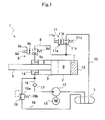
- a cylinder device 1 is basically constituted as a single-rod cylinder device, as shown in Fig. 1 , which includes a cylinder 2; a piston 3 inserted slidably into the cylinder 2; a rod 4 inserted into the cylinder 2 and connected to the piston 3; a rod-side chamber 5 and a piston-side chamber 6 partitioned by the piston 3 within the cylinder 2; a tank 7; a first on-off valve 9 provided in the middle of a first passage 8 allowing the rod-side chamber 5 to communicate with the piston-side chamber 6; a second on-off valve 11 provided in the middle of a second passage 10 allowing the piston-side chamber 6 to communicate with the tank 7; and a pump 12 for supplying liquid to the rod-side chamber 5.
- the rod-side chamber 5 and the piston-side chamber 6 are filled with liquid such as hydraulic oil, and the tank 7 is filled with gas in addition to the liquid.
- the inside of the tank 7 does not have to be in a pressurized state particularly by filling the gas with pressure
- the cylinder device 1 can be driven to extend by laying the first passage 8 in a communicating state by the first on-off valve 9 and driving the pump 12 with the second on-off valve 11 being closed, and the cylinder device 1 can be driven to contract by laying the second passage 10 in a communicating state and driving the pump 12 with the first on-off valve 9 being closed.
- the cylinder 2 has a cylindrical shape with the right end in Fig. 1 being closed by a lid 13, and an annular rod guide 14 being attached to the left end in Fig. 1 .
- the rod 4 to be inserted movably into the cylinder 2 is inserted slidably into the rod guide 14.
- One end of the rod 4 is protruded out of the cylinder 2, and the other end within the cylinder 2 is connected to the piston 3 similarly inserted slidably into the cylinder 2.
- the gap between the outer circumference of the rod 4 and the cylinder 2 is sealed by a seal member not shown, whereby the inside of the cylinder 2 is maintained in a sealed state.
- the rod-side chamber 5 and the piston-side chamber 6 partitioned by the piston 3 within the cylinder 2 are filled with hydraulic oil as the liquid as described above.
- the sectional area of the rod 4 is set to a half of the sectional area of the piston 3, so that the pressure receiving area on the rod-side chamber 5 side in the piston 3 is a half of the pressure receiving area on the piston-side chamber 6 side.
- the rod-side chamber 5 is in communication with the piston-side chamber 6 to equalize the pressures within the rod-side chamber 5 and the piston-side chamber 6 to each other, and a thrust obtained by multiplying the pressure receiving area difference between the rod-side chamber 5 side and the piston-side chamber 6 side in the piston 3 by the above-mentioned pressure is generated, and when the cylinder device 1 is driven to contract reversely, a thrust obtained by multiplying the pressure of the rod-side chamber 5 by the pressure receiving area on the rod-side chamber 5 side in the piston 3 is generated since the communication between the rod-side chamber 5 and the piston-side chamber 6 is interrupted, and the piston-side chamber 6 is in communication with the tank 7.
- the generated thrust of the cylinder device 1 thus corresponds to a value obtained by multiplying a half of the sectional area of the piston 3 by the pressure of the rod-side chamber 5 in both the extension and the contraction. Therefore, the thrust of the cylinder device 1 can be controlled by controlling the pressure of the rod-side chamber 5 in both the extending drive and the contracting drive.
- the pressure receiving area on the rod-side chamber 5 side in the piston 3 is set to a half of the pressure receiving area on the piston-side chamber 6 side, the following advantages are provided: the control is simplified when the same thrust is generated on both extending side and contracting side since the pressure of the rod-side chamber 5 is the same on both the extending side and the contracting side and, in addition, the same responsiveness is secured on both the extending side and contracting side since the flow rate to displacement is the same. Even if the pressure receiving area on the rod-side chamber 5 side in the piston 3 is not set to a half of the pressure receiving area on the piston-side chamber 6 side, the thrusts on both the extending and contracting sides of the cylinder device 1 can be controlled by the pressure of the rod-side chamber 5.
- a lid 13 for closing the left end of the rod 4 and the right end of the cylinder 2 in Fig. 1 includes an attachment portion not shown, so that the cylinder device 1 can be interposed between a vehicle body and an axle in a vehicle.
- the rod-side chamber 5 and the piston-side chamber 6 are allowed to communicate with each other by the first passage 8, and the first on-off valve 9 is provided in the middle of the first passage 8.
- the first passage 8 may be provided in the piston 3 although the communication between the rod-side chamber 5 and the piston-side chamber 6 is performed outside the cylinder 2.
- the first on-off valve 9 is composed of a solenoid on-off valve in this embodiment, including a valve 9a which includes a communicating position 9b for opening the first passage 8 to allow the rod-side chamber 5 to communicate with the piston-side chamber 6 and an interrupting position 9c for interrupting the communication of the rod-side chamber 5 with the piston-side chamber 6; a spring 9d which biases the valve 9a so as to be located at the interrupting position 9c; and a solenoid 9e which switches the valve 9a to the communicating position 9b against the spring 9d in current-carrying.
- a solenoid on-off valve in this embodiment, including a valve 9a which includes a communicating position 9b for opening the first passage 8 to allow the rod-side chamber 5 to communicate with the piston-side chamber 6 and an interrupting position 9c for interrupting the communication of the rod-side chamber 5 with the piston-side chamber 6; a spring 9d which biases the valve 9a so as to be located at the interrupting position 9c; and a sole
- the piston-side chamber 6 and the tank 7 are allowed to communicate with each other by the second passage 10, and the second on-off valve 11 is provided in the middle of the second passage 10.
- the second on-off valve 11 is composed of a solenoid on-off valve in this embodiment, including a valve 11a which includes a communicating position 11b for opening the second passage 10 to allow the piston-side chamber 6 to communicate with the tank 7 and an interrupting position 11c for interrupting the communication of the piston-side chamber 6 with the tank 7; a spring 11d which biases the valve 11a so as to be located at the interrupting position 11c; and a solenoid 11e which switches the valve 11a to the communicating position 11b against the spring 11d in current-carrying.
- the pump 12 is driven by a motor 15 in this embodiment.
- the pump 12 is configured to discharge liquid only in one direction with a discharge port being allowed to communicate with the rod-side chamber 5 by a supply passage 16 and a suction port being allowed to communicate with the tank 7, so that it sucks, when driven by the motor 15, liquid from the tank 7 and discharges the liquid to the rod-side chamber 5.
- the pump 12 is free from problems such as the change in discharge quantity in rotation switching since it only discharges the liquid in one direction without the switching operation of rotating direction as described above, and an inexpensive gear pump or the like can be employed. Further, since the rotating direction of the pump 12 is regularly constant, no high responsiveness to rotation switching is required for the motor 15 as the drive source for driving the pump 12, and an inexpensive one can be used as the motor 15 to this extent.
- a check valve 17 is provided in the middle of the supply passage 16 to arrest the backflow of the liquid from the rod-side chamber 5 to the pump 12.
- the rod-side chamber 5 is connected to the tank 7 through a passage 18, and a relief valve 19 is provided in the middle of the passage 18 to open the passage 18 at a preset valve opening pressure.
- the relief valve 19 is configured so that, when the pressure of the rod-side chamber 5 on the upstream side of the passage 18 to be applied onto a valve element 19a exceeds the valve opening pressure, a thrust resulting from the above-mentioned pressure which presses the valve element 19a in the direction of opening the passage 18 overcomes the biasing force of the spring 19b biasing the valve element 19a in the direction of interrupting the passage 18 to retreat the valve element 19a, whereby the passage 18 is opened.
- the relief valve 19 opens the passage 18, if the pressure of the rod-side chamber 5 exceeds the valve opening pressure due to an extending/contracting-directional excessive input to the cylinder device 1, regardless of the opening and closing state of the first on-off valve 9 and the second on-off valve 11, to allow the rod-side chamber 5 to communicate with the tank 7, whereby the pressure within the rod-side chamber 5 is released to the tank 7 to protect the overall system of the cylinder device 1.
- the thrust of the cylinder device 1 can be controlled to a desired value by on/off- controlling the first on-off valve 9 and the second on-off valve 11 to adjust the pressure of the rod-side chamber 5.
- the motor 15 is driven with the first on-off valve 9 being at the communicating position 9b to supply the liquid from the pump 12 into the cylinder 2.
- the liquid is supplied from the pump 12 to both the rod-side chamber 5 and the piston-side chamber 6 which are in communication with each other to press the piston 3 to the left in Fig. 1 , whereby the cylinder device 1 develops extending operation.
- the second on-off valve 11 is opened and closed to adjust the pressure of the rod-side chamber 5 so that the value obtained by multiplying the pressure of the rod-side chamber 5 by the pressure receiving area difference between the piston-side chamber 6 side and the rod-side chamber 5 side in the piston 3 is equalized to the desired thrust. Since the pressure of the piston-side chamber 6 is equal to the pressure of the rod-side chamber 5, the pressure of the piston-side chamber 6 is also controlled by controlling the pressure of the rod-side chamber 5.
- the thrust in the extending direction of the cylinder device 1 can be obtained as designed by opening the second on-off valve 11, when the pressure of the rod-side chamber 5 is too high to obtain the desired thrust, to release the pressures of the piston-side chamber 6 and the rod-side chamber 5 to the tank 7, and closing the second on-off valve 11, when the pressure of the rod-side chamber 5 is too low to obtain the desired thrust to the contrary, to raise the pressures of the piston-side chamber 6 and the rod-side chamber 5 through the liquid supply from the pump 12. Therefore, this control can be performed by sensing the pressure of only the rod-side chamber 5.
- a desired extending-directional thrust opposing it can be obtained by on/off-controlling the second on-off valve 11 in a state where the liquid is supplied from the pump 12 into the cylinder 2 by driving the motor 15 with the first on-off valve 9 being at the communicating position 9b similarly to the case where the extending-directional thrust is obtained with extension. Since the cylinder device 1 is in a state in which it exerts no thrust more than external force in this case, it is only necessary to cause the cylinder device 1 to function as damper. Therefore, the desired thrust can be obtained even by on/off-controlling the second on-off valve 11 with the first on-off valve 9 being at the communicating position 9b while stopping the liquid supply from the pump 12.
- the motor 15 is driven with the second on-off valve 11 being at the communicating position 11b to supply the liquid from the pump 12 into the cylinder 2.
- the first on-off valve 9 is opened and closed to adjust the pressure of the rod-side chamber 5 so that the value obtained by multiplying the pressure of the rod-side chamber 5 by the pressure receiving area of the rod-side chamber 5 side in the piston 3 is equalized to the desired thrust.
- the thrust in the contracting direction of the cylinder device 1 can be obtained as designed by opening the first on-off valve 9, when the pressure of the rod-side chamber 5 is too high to obtain a desired thrust, to release the pressure of the rod-side chamber 5 to the tank 7 through the opened second passage 10, and closing the first on-off valve 9, when the pressure of the rod-side chamber 5 is too low to obtain the desired thrust to the contrary, to raise the pressure of the rod-side chamber 5 through the liquid supply from the tank 12.
- a desired contracting-directional thrust opposing it can be obtained by on/off-controlling the first on-off valve 11 in a state where the liquid is supplied from the pump 12 into the cylinder 2 by driving the motor 15 with the second on-off valve 11 being at the communicating position 11b to supply the liquid from the pump 12 into the cylinder 2, similarly to the case where the contracting-directional thrust is obtained with contraction.
- the cylinder device 1 since the cylinder device 1 is in a state where it exerts no thrust more than external force, it is only necessary to cause the cylinder device 1 to function as damper. Therefore, the desired thrust can be obtained even by on/off-controlling the first on-off valve 9 with the second on-off valve 11 being at the communicating position 11b while interrupting the liquid supply from the pump 12.
- the cylinder device 1 fulfills the function as actuator in this manner. Since this cylinder device 1 is set to the single-rod type, the stroke length can be easily secured, compared with the double-rod cylinder device, and the overall length of the cylinder device can be reduced to improve the mountability on various vehicles including railroad vehicle.
- the manufacture of the cylinder device 1 can be performed without constraints such as assembling in liquid or assembling under vacuumed environment, and the high-level deaeration of liquid is also dispensed with, the reduction in manufacturing cost can be attained in addition to the improvement in productivity.
- the cylinder device 1 is improved in the calmness without the problem of rattling of the low-pressure priority shuttle valve, and can be mounted on a vehicle without giving a sense of unpleasant or uneasiness to the vehicle occupants.
- the pump 12 discharges only in one direction without capacitive fluctuations in rotation switching, an inexpensive pump 12 can be employed, and since the high responsiveness in switching of rotating direction is not required for the motor 15 that is the driving source of the pump 12, an inexpensive motor 15 can be employed. Consequently, the cylinder device 1 is reduced in the cost as the whole, and improved in the economic efficiency.
- This cylinder device 1 when forcedly extended and contracted by external force, can behave as a damper by stopping the drive of the pump 12, and can suppress the vibration of a vibration control object by semiactive control typified by skyhook semiactive control, as well as suppressing the vibration of the vibration control object by the active control by the behavior as actuator.
- the cylinder device 1 can be controlled by selecting, of the active control and the semiactive control, the one most suitable to vibration suppression according to the vibration mode, the vibration suppressing effect on the vibration control object is improved.
- the cylinder device 1 When the cylinder device 1 is operated as the damper to execute the skyhook semiactive control, the cylinder device 1 is controlled to exert a thrust obtained by multiplying a skyhook damping factor by a relative speed of the cylinder 2 and the rod 4 of the cylinder device 1 when the vibrating direction of the vibration control object is matched to the relative direction of the cylinder device 1, and to minimize the thrust of the cylinder device 1 as much as possible when the vibrating direction of the vibration control object is differed from the relative direction of the cylinder device 1.
- control can be performed by on/off-controlling the first on-off valve 9 and the second on-off valve 11 so as to satisfy the above-mentioned condition, and the thrust of the cylinder device 1 can be minimized by locating both the first on-off valve 9 and the second on-off valve 11 at the communicating positions 9b and 11b.
- the check valve 17 is provided in the middle of the supply passage 16 on the downstream of the pump 12, the backflow of the liquid from the rod-side chamber 5 to the pump 12 is arrested even if the cylinder device 1 is forcedly extended and contracted by external force.
- a thrust more than the thrust by the torque of the motor M can be obtained by opening and closing the first on-off valve 9 and the second on-off valve 11 to operate the cylinder device 1 as damper.
- the thrust of the cylinder device can be controlled to a desired value by adjusting the pressure of the rod-side chamber 5 through control of the torque of the motor 15.
- the check valve 17 provided in the supply passage 16 can be abolished as in a cylinder device 1a as one modified example of the one embodiment shown in Fig. 2 .
- the motor 15 is driven with the first on-off valve 9 being at the communicating position 9b and the second on-off valve 11 being at the interrupting position 11c to supply the liquid from the pump 12 into the cylinder 2.
- the liquid is supplied from the pump 12 to both the rod-side chamber 5 and the piston-side chamber 6 which are in communication with each other to press the piston 3 to the left in Fig. 2 , whereby the cylinder device 1a develops extending operation.
- the torque of the motor 15 is adjusted to control the pressure of the rod-side chamber 5 so that the value obtained by multiplying the pressure of the rod-side chamber 5 by the pressure receiving area difference between the piston-side chamber 6 side and the rod-side chamber 5 side in the piston 3 is equalized to the desired thrust.
- the pressure of the rod-side chamber 5 can be controlled by adjusting the torque of the motor 15 which is proportional to the discharge pressure of the pump 12.
- the thrust in the extending direction of the cylinder device 1a can be obtained as designed by reducing the torque of the motor 15, when the pressure of the rod-side chamber 5 is too high to obtain a desired thrust, to reduce the pressure of the rod-side chamber 5, and increasing the torque of the motor 15, when the pressure of the rod-side chamber 5 is too low to obtain the desired thrust to the contrary, to raise the pressure of the piston-side chamber 6 and the rod-side chamber 5.
- this control can performed by directly sensing the torque of the motor 15 or sensing the current carried to a winding wire of the motor 15 to obtain the generation torque of the motor 15.
- a desired extending-directional thrust opposing it can be obtained by adjusting the torque of the motor 15 with the first on-off valve 9 being at the communicating position 9b and the second on-off valve 11 being at the interrupting position 11c, similarly to the case where the extending-directional thrust is obtained with extension.
- the motor 15 is never driven to reversely rotate since the motor 15 is regularly instructed to normally rotate the pump 12 in spite of the reverse rotation of the motor 15 and the pump 12.
- the cylinder device 1a since the cylinder device 1a is in a state where it exerts no thrust more than external force, it is only necessary to cause the cylinder device 1a to function as damper. Therefore, the desired thrust can be obtained even by on/off-controlling the second on-off valve 11 with the first on-off valve 9 being at the communicating position 9b while interrupting the liquid supply from the pump 12.
- the motor 15 is driven with the first on-off valve 9 being at the interrupting position 9c and the second on-off valve 11 being at the communicating position 11b to supply the liquid from the pump 12 into the cylinder 2.
- the torque of the motor 15 is adjusted to control the pressure of the rod-side chamber 5 so that the value obtained by multiplying the pressure of the rod-side chamber 5 by the pressure receiving area on the rod-side chamber 5 side in the piston 3 is equalized to the desired thrust.
- the thrust in the contracting direction of the cylinder device 1a can be obtained as designed by reducing the torque of the motor 15, when the pressure of the rod-side chamber 5 is too high to obtain the desired thrust, to reduce the pressure of the rod-side chamber 5, and increasing the torque of the motor 15, when the pressure of the rod-side chamber 5 is too small to obtain the desired thrust, to raise the pressure of the rod-side chamber 5.
- a desired contracting-directional thrust force opposing it can be obtained by adjusting the torque of the motor 15 with the first on-off valve 9 being at the interrupting position 9c and the second on-off valve 11 being at the communicating position 11b, similarly to the case where the contracting-directional thrust is obtained with contraction.
- the cylinder device 1a since the cylinder device 1a in a state where it exerts no thrust more than external force, it is only necessary to cause the cylinder device 1a to function as damper. Therefore, the desired thrust force can be obtained even by on/off-controlling the first on-off valve 9 with the second on-off valve 11 being at the communicating position 11b while interrupting the liquid supply from the pump 12.
- the cylinder device 1a can fulfill the function as actuator also by controlling the torque of the motor 15, and can produce various function effects in the cylinder device 1 of the one embodiment described above since it has the same principle of thrust generation with increased variations of control method.
- This cylinder device 1a also, when forcedly extended and contracted by external force, can behave as a damper and can suppress the vibration of a vibration control object by semiactive control, as well as suppressing the vibration of the vibration control object by the active control by the behavior as actuator.
- a cylinder device 1b as the other modified example of the one embodiment shown in Fig. 3 is described.
- the passage 18 and the relief valve 19 in the cylinder device 1 of the one embodiment are abolished
- the rod-side chamber 5 is connected to the tank 7 through a discharge passage 21 instead
- a variable relief valve 22 capable of changing valve opening pressure is provided in the middle of the discharge passage 21.
- the variable relief valve 22 includes a valve element 22a provided in the middle of the discharge passage 21; a spring 22b which biases the valve element 22a to interrupt the discharge passage 21; and a proportional solenoid 22c which generates a thrust opposed to the spring 22b in current-carrying, and can adjust the valve opening pressure by adjusting the current to be carried to the proportional solenoid 22c.
- variable relief valve 22 is configured so that, when the pressure of the rod-side chamber 5 on the upstream side of the discharge passage 21 to be applied onto the valve element 22a exceeds a relief pressure, the resultant force of a thrust resulting from the above-mentioned pressure which presses the valve element 22a in the direction of opening the discharge passage 21 and a thrust by the proportional solenoid 22c overcomes the biasing force of the spring 22b biasing the valve element 22a in the direction of interrupting the discharge passage 21 to retreat the valve element 22a, whereby the discharge passage 21 is opened.
- the thrust generated by the proportional solenoid 22c can be increased by increasing the amount of current to be supplied to the proportional solenoid 22c, and the valve opening pressure is minimized when the current is supplied to the proportional solenoid 22c to a maximum extent, and maximized when no current is supplied to the proportional solenoid 22c.
- variable relief valve 22 is configured to open the discharge passage 21, if the pressure of the rod-side chamber 5 exceeds the valve opening pressure due to excessive extending-directional input to the cylinder device 1b, regardless of the opening and closing state of the first on-off valve 9 and the second on-off valve 11, to allow the rod-side chamber 5 to communicate with the tank 7 to release the pressure in the rod-side chamber 5 to the tank 7, whereby the overall system of the cylinder device 1b is protected.
- the thrust of the cylinder device 1b when caused to operate as actuator, can be controlled by controlling the pressure of the rod-side chamber 5 through adjustment of the valve opening pressure of the variable relief valve 22, in addition to the above-mentioned two concrete methods. That is, the pressure of the rod-side chamber 5 is controlled by the variable relief valve 22, and the direction of thrust is determined by the first on-off valve 9 and the second on-off valve 11.
- the motor 15 is driven with the first on-off valve 9 being at the communicating position 9b and the second on-off valve 11 being at the interrupting position 11c to supply the liquid from the pump 12 into the cylinder 2.
- the current of the proportional solenoid 22c is adjusted to control the valve opening pressure so that the value obtained by multiplying the valve opening pressure of the variable relief valve 22 by the pressure receiving area difference between the piston-side chamber 6 side and the rod-side chamber 5 side in the piston 3 is equalized to the desired thrust.
- variable relief valve 22 since the variable relief valve 22 is opened, when the pressure of the rod-side chamber 5 that is equal to the pressure of the piston-side chamber 6 exceeds the valve opening pressure of the variable relief valve 22, to release the pressures of the piston-side chamber 6 and the rod-side chamber 5 to the tank 7, and the variable relief valve 22 is closed, when the pressure of the rod-side chamber 5 is below the valve opening pressure of the variable relief valve 22, to raise the pressure of the piston-side chamber 6 and the rod-side chamber 5 through the liquid supply from the pump 12, the pressure of the piston-side chamber 6 and the rod-side chamber 5 is consequently controlled to the valve opening pressure of the variable relief valve 22, whereby the thrust in the extending direction of the cylinder device 1b can be obtained as designed.
- this control can be performed by acquiring a relationship between the current of the proportional solenoid 22c and the valve opening pressure in the variable relief valve 22, and open-loop control can be performed. Further, feedback control may be performed by use of a current loop while sensing the current-carrying amount to the proportional solenoid 22c, and the feedback control can be performed also by sensing the pressure of the rod-side chamber 5.
- a desired extending-directional thrust opposing it can be obtained by adjusting the valve opening pressure of the variable relief valve 22 in a state where the liquid is supplied from the pump 12 into the cylinder 2 by driving the motor 15 with the first on-off valve 9 being at the communicating position 9b and the second on-off valve 11 being at the interrupting position 11c, similarly to the case where the extending-directional thrust is obtained with extension.
- the desired thrust can be obtained even by controlling the valve opening pressure of the variable relief valve 22 with the first on-off valve 9 being at the communicating position 9b and the second on-off valve 11 being at the interrupting position 11c while interrupting the liquid supply from the pump 12.
- the motor 15 is driven with the first on-off valve 9 being at the interrupting position 9c and the second on-off valve 11 being at the communicating position 11b to supply the liquid from the pump 12 into the cylinder 2.
- the amount of current of the proportional solenoid 22c is adjusted to control the valve opening pressure so that the value obtained by multiplying the valve opening pressure of the variable relief valve 22 by the pressure receiving area on the rod-side chamber 5 side in the piston 3 is equalized to the desired thrust.
- variable relief valve 22 since the variable relief valve 22 is opened, when the pressure of the rod-side chamber 5 exceeds the valve opening pressure of the variable relief valve 22, to release the pressure to the tank 7, and the variable relief valve 22 is closed, when the pressure of the rod-side chamber 5 is below the valve opening pressure of the variable relief valve 22, to raise the pressure of the rod-side chamber 5 through the liquid supply from the pump 12, the pressure of the rod-side chamber 5 is consequently controlled to the valve opening pressure of the variable relief valve 22, whereby the thrust in the extending direction of the cylinder device 1b can be obtained as designed.
- the piston-side chamber 6 never interferes with the contracting operation of the cylinder device 1b since it is allowed to communicate with the tank 7 by the communicating position 11b of the second on-off valve 11.
- a desired contracting-directional thrust opposing it can be obtained by adjusting the valve opening pressure of the variable relief valve 22 in a state where the liquid is supplied from the pump 12 into the cylinder 2 by driving the motor 15 with the first on-off valve 9 being at the interrupting position 9c and the second on-off valve 11 being at the communicating position 11b, similarly to the case where the contracting-directional thrust is obtained with contraction.
- the cylinder device 1b since the cylinder device 1b is in a state where it exerts no thrust more than external force, it is only necessary to cause the cylinder device 1b to function as damper. Therefore, the desired thrust can be obtained even by controlling the valve opening pressure of the variable relief valve 22 with the first on-off valve 9 being at the interrupting position 9c and the second on-off valve 11 being at the communicating position 11b while interrupting the liquid supply from the pump 12.
- the thrust can be controlled by controlling the valve opening pressure of the variable relief valve 22, in addition to the control methods of the cylinder devices 1 and 1a of the one embodiment and the one modified example thereof, so that the function as actuator can be fulfilled.
- the cylinder device 1b can provide various function effects in the cylinder device 1 of the above-mentioned embodiment since it has the same principle of thrust generation with increased variations of the control method.
- the magnitude of thrust can be controlled by controlling the valve opening pressure of the variable relief valve 22, the advantage that the thrust of the cylinder device 1b can be adjusted, without particular sensing of other state quantities, only by acquiring the amount of current to be supplied to the proportional solenoid 22c and the valve opening pressure can be enjoyed.
- this cylinder device 1b also, when forcedly extended and contracted by external force, can behave as a damper by stopping the drive of the pump 12 to adjust the thrust by controlling the valve opening pressure of the variable relief valve 22, and thus can suppress the vibration of the vibration control object by skyhook semiactive control, as well as suppressing the vibration of the vibration control object by the active control by the behavior as actuator.
- the thrust of the cylinder device 1b can be minimized by locating both the first on-off valve 9 and the second on-off valve 11 at the communicating positions 9b and 11b.
- a cylinder device 1c as an additional modified example of the one embodiment shown in Fig. 4 is described.
- the first on-off valve 9 and the second on-off valve 11 of the cylinder device 1b of the other modified example of the one embodiment are replaced by a first on-off valve 23 and a second on-off valve 24 respectively.
- the first on-off valve 23 is composed of a solenoid on-off valve in this embodiment, including a valve 23a including a communicating position 23b for opening the first passage 8 to allow the rod-side chamber 5 to communicate with the piston-side chamber 6 and an interrupting position 23c for permitting only the flow from the piston-side chamber 6 to the rod-side chamber 5; a spring 23d which biases the valve 23a to be located at the interruption position 23c; and a solenoid 23e which switches the valve 23a to the communicating position 23b against the spring 23d in current-carrying.
- the second on-off valve 24 provided in the middle of the second passage 10 is composed of a solenoid on-off valve in this embodiment, including a valve 24a including a communicating position 24b for opening the second passage 10 to allow the piston-side chamber 6 to communicate with the tank 7 and an interrupting position 24c for permitting only the flow from the tank 7 to the piston-side chamber 6; a spring 24d which biases the valve 24a to be located at the interruption position 24c; and a solenoid 24e which switches the valve 24a to the communicating position 24b against the spring 24d in current-carrying.
- a solenoid on-off valve in this embodiment, including a valve 24a including a communicating position 24b for opening the second passage 10 to allow the piston-side chamber 6 to communicate with the tank 7 and an interrupting position 24c for permitting only the flow from the tank 7 to the piston-side chamber 6; a spring 24d which biases the valve 24a to be located at the interruption position 24c; and a solenoid 24e which switches the valve 24a to
- the cylinder device 1c in a state where the first on-off valve 23 is located at the interrupting position 23c and the second on-off valve 24 is located at the interrupting position 24c, the cylinder device 1c, when forcedly extended and contracted by external force, behaves as a damper the damping force of which is adjusted by the variable relief valve 22. More specifically, when the cylinder device 1c is extended, the capacity of the piston-side chamber 6 is extended to suck the liquid from the tank 7 through the interrupting position 24c of the second on-off value 24, while the rod-side chamber 5 is compressed to discharge the liquid to the tank 7 through the discharge passage 21.
- the damping force of suppressing the extension of the cylinder device 1c is developed by presenting a resistance to this flow of liquid in the discharge passage 21 by the variable relief valve 22.
- the piston-side chamber 6 is compressed to cause the liquid in the piston-side chamber 6 to flow into the extending rod-side chamber 5 through the interrupting position 23c of the first on-off valve 23, and the surplus liquid within the cylinder 2 which corresponds to the penetrating volume of the rod 4 into the cylinder 2 is discharged to the tank 7 through the discharge passage 21.
- the flow of liquid is a one-way flow circulating in order through the piston-side chamber 6, the rod-side chamber 5 and the tank 7, and the damping force of suppressing the compression of the cylinder device 1c is developed by presenting a resistance, when the liquid discharged from the cylinder 2 by the extending and contracting operation of the cylinder device 1c is passed through the discharge passage 21, to this flow of liquid by the variable relief valve 22. That is, the cylinder device 1c behaves as a uniflow damper when both the first on-off valve 23 and the second on-off valve 24 are located at the interrupting positions 23c and 24c.
- the device 1c since the valves 23a and 24a of the first on-off valve 23 and the second on-off valve 24 are pressed by the springs 23d and 24d and located respectively at the interrupting positions 23c and 24c in the event of current-carrying failure, and the variable relief valve 22 behaves as a pressure control valve with the valve opening pressure being maximized, the device 1c can automatically behave as a passive damper in the event of failure such as current-carrying failure.
- the thus-configured cylinder device 1 Since the damping forces generated in both extension and contraction can be equalized, if the piston speed is the same in both the extension and the contraction, by setting the pressure receiving area on the rod-side chamber 5 side in the piston 3 to a half of the pressure receiving area on the piston-side chamber 6 side, the thus-configured cylinder device 1, particularly, can be most suitably applied to a vibration control object having no polarity in vibrating direction such as relative vibrations of a vehicle body and a truck in railroad vehicle.
- the interrupting position 23c of the first on-off valve 23 behaves as a flow straightening passage which permits only the flow of liquid from the piston-side chamber 6 to the rod-side chamber 5 in cooperation with the first passage 8
- the interrupting position 24c of the second on-off valve 23 behaves as a suction passage which permits only the flow of liquid from the tank 7 to the piston-side chamber 6 in cooperation with the second passage 10.
- the flow straightening passage may adopt a structure in which a passage allowing the piston-side chamber 6 to communicate with the rod-side chamber 5 is provided independently from the first passage 8 with a check valve being provided in the middle of the passage, although it can be consolidated to the interrupting position 23c of the first on-off valve 23 and the first passage 8, and may be provided, for example, on the piston 3.
- the suction passage may also adopt a structure in which a passage allowing the piston-side chamber 6 to communicate with the tank 7 is provided independently from the second passage 10 with a check valve being provided in the middle of the passage, although it can be consolidated to the interrupting position 24c of the second on-off valve 24 and the second passage 10, and may be provided, for example, on the lid 13.
- the rod-side chamber 5 is connected to the tank 7 through a limiting passage 25, and an orifice 26 is provided in the middle of the limiting passage 25 to present a resistance to the flow of liquid passing therethrough.
- the cylinder device 1c When the cylinder device 1c is assembled, the cylinder device 1c is operated to extend and contract as it is in a uniflow damper state by closing the first on-off valve 23, the second on-off valve 24 and the variable relief valve 22 to circulate the liquid to the cylinder 2 and the tank 7 through the limiting passage 25, whereby deaeration of the cylinder 2 can be performed by discharging liquid with the probability of gas entrapment to the tank 7 and sucking liquid free from the probability of gas entrapment from the tank 7 to the cylinder 2.
- the limiting passage 25 behaves as a deaerating passage, so that the flow rate passing through the limiting passage 25 is largely limited, in general operation, by the orifice 26 as resistance, and the loss in passage of the liquid through the limiting passage 25 is minimized when the cylinder device 1c is caused to function as actuator.
- the damping force may be generated by the orifice 26 in cooperation with the variable relief valve 22 and, further, development of damping force can be surely performed by the orifice 26 alone in a state such that the variable relief valve 22 cannot be opened.
- the above-mentioned limiting passage 25 and orifice 26 can be provided within the circuit of each of the cylinder devices 1, 1a and 1b of the above-mentioned embodiments.
- the cylinder device 1c of the other embodiment can be controlled to operate as actuator by the same method as that of the above-mentioned cylinder device 1b. That is, the magnitude and direction of thrust may be controlled only by on/off-control of the first on-off valve 23 and the second on-off valve 24, or the direction of thrust may be controlled by the first on-off valve 23 and the second on-off valve 24 while controlling the magnitude of thrust by the torque control of the motor 15, or the direction of thrust is controlled by the first on-off valve 23 and the second on-off valve 24 while controlling the magnitude of thrust by the valve opening pressure of the variable relief valve 22.
- a desired thrust can be obtained by interrupting the liquid supply from the pump 12 and controlling the valve opening pressure of the variable relief valve 22 with the second on-off valve 24 being at the interrupting position 24c. Since the first on-off valve 23 permits the flow of liquid from the piston-side chamber 6 to the rod-side chamber 5 by the interrupting position 23c, and allows contraction of the cylinder device 1c even when it is located at the interrupting position 23c, the first on-off valve 23 can be located at any of the communicating position 23b and the interrupting position 23c when the cylinder device 1c is caused to perfectly behave as a passive damper without skyhook semiactive control which will be described below.
- a desired thrust can be obtained by interrupting the liquid supply from the pump 12 and controlling the valve opening pressure of the variable relief valve 22 with the first on-off valve 23 being at the interrupting position 23c.
- the second on-off valve 24 permits the flow of liquid from the tank 7 to the piston-side chamber 6 by the interrupting position 24c, and allows extension of the cylinder device 1c even if it is located at the interrupting position 24c, the second on-off valve 24 can be located at any of the communicating position 24b and the interrupting position 24c when the cylinder device 1c is caused to perfectly behave as a passive damper without the skyhook semiactive control to be described below.
- the cylinder device 1c of the other modified example also can fulfill the function as actuator, since the variable relief valve 22 is provided in the middle of the discharge passage 21 allowing the rod-side chamber 5 to communicate with the tank 7, by optionally selecting one of the control methods of the cylinder devices 1, 1a and 1b of the above-mentioned embodiments.
- the cylinder device 1c can develop various function effects in the cylinder device 1 of the one embodiment described above since it has the same structure of thrust generation as the cylinder device 1 with increased variations of control method.
- the magnitude of thrust can be similarly controlled by controlling the valve opening pressure of the variable relief valve 22, the advantage that the thrust of the cylinder device 1b can be adjusted without particular sensing only by acquiring the amount of current to be supplied to the proportional solenoid 22c and the valve opening pressure can be enjoyed also in this case.
- the cylinder device 1c when forcedly extended and contracted by external force, can be caused to behave as a passive uniflow damper without control of the first on-off valve 23 and the second on-off valve 24 since the flow straightening passage and the suction passage are not particularly provided, and can surely develop the damper function in the event of current-carrying failure.
- the cylinder device 1c can behave as the actuator by driving the pump 12 and also as the damper by stopping the drive of the pump 12 to adjust the thrust through control of the valve opening pressure of the variable relief valve 22. Therefore, this cylinder device can suppress the vibration of the vibration control object not only by the active control by the behavior as actuator but also by the skyhook semiactive control.
- the first on-off valve 23 is located at the communicating position 23b, and the second on-off valve 24 are located at the interrupting position 24c, and when the thrust of the cylinder device 1c is minimized in contracting operation, the first on-off valve 23 is located at the interrupting position 23c, and the second on-off valve 24 is located at the communicating position 24b respectively.
- the damping force can be exerted in extending operation to suppress it by locating the first on-off valve 23 at the interrupting position 23c and locating the second on-off valve 24 at the communicating position 24c, and if only the extending and contracting direction of the cylinder device 1c is switched without switching of the vibrating direction of the vibration control object, the damping force of the cylinder device 1c is minimized or the vibration control object is never excited since the first on-off valve 23 is at the interrupting position 23c and the second on-off valve 24 is at the communicating position 24c.
- the damping force can be exerted to suppress it by locating the first on-off valve 23 at the communicating position 23b and locating the second on-off valve 24 at the interrupting position 24b, and if only the extending and contracting direction of the cylinder device 1c is switched without switching of the vibrating direction of the vibration control object, the damping force of the cylinder device 1c is minimized or the vibration control object is never excited since the first on-off valve 23 is at the communicating position 23c and the second on-off valve 24 is at the interrupting position 23b.
- the operation load on the skyhook semiactive control is reduced, and the control of the first on-off valve 23 and the second on-off valve 24 is simplified, since the control device 1c mechanically conforms the damping force to zero in the skyhook semiactive control, without polarity determination by the Carnap's theory when the vibrating direction of the vibration control object is differed from the relative direction of the cylinder device 1.
- an outer cylinder 27 is provided on the outer circumference of the cylinder 2, and the tank 7 is provided between the cylinder 2 and the outer cylinder 27.
- the limiting passage 25 and the orifice 26 can be provided in the upper thickness in Fig. 4 of the cylinder 2, whereby when the cylinder device 1c is horizontally placed as shown in the drawing, the gas entrapped into the cylinder 2 can be rapidly discharged to the tank 7 to enjoy the advantage that the deterioration in responsiveness of the cylinder device 1c can be instantaneously resolved.
- the outer cylinder 27 can be applied to each of the above-mentioned embodiments.
- variable relief valve 22 in the above-mentioned cylinder devices 1b and 1c can be changed to a variable relief valve 30 shown in Fig. 5 .
- the variable relief valve 30 of Fig. 5 includes a proportional solenoid 31; a damping passage 32 connected to the middle of the discharge passage 21; a relief passage 33 juxtaposed with the damping passage 32; a selector valve element 34 biased to open the damping passage 32 and set to close the damping passage 32 in current-carrying to a proportional solenoid, the selector valve element presenting a resistance to the flow of liquid when the damping passage is opened; and a relief valve element 35 biased to close the relief passage 33, the valve opening pressure of which is reduced according to the current-carrying amount in the current-carrying to the proportional solenoid.
- a pushrod 36 extending toward the relief valve element 35 is connected to the selector valve element 34, and when current is carried to the proportional solenoid 31, the selector valve element 34 is pressed by the proportional solenoid 31 and switched to an interrupting position, and the pushrod 36 is allowed to abut on the relief valve element 35, whereby the thrust of the proportional solenoid 31 can be applied onto the relief valve element 35.
- the valve opening pressure of the relief valve element 35 can be controlled by adjusting the current-carrying amount to the proportional solenoid 31.
- variable relief valve 30 behaves as a throttle valve since the selector valve element 34 opens the damping passage 32 to present a resistance to the flow of hydraulic oil passing therethrough, and the relief valve element 35 with the valve opening pressure being maximized opens the relief passage 33, in response to an excessive input, to fulfill the relief function.
- the relief valve element 35 opens the relief valve 33 at the valve opening pressure adjusted according to the current-carrying amount to the proportional solenoid 31, since the selector valve element 34 interrupts the damping passage 32, to fulfill the relief function.
- the magnitude of the thrust as actuator of the cylinder devices 1b and 1c can be controlled also by use of such a proportional solenoid variable relief valve 30 to respond to both the active control and the semiactive control. Further, since this valve behaves as a throttle valve in the event of failure, the cylinder device 1c, when this valve is applied to the cylinder device 1c, can behave as a passive damper which develops a damping force by the variable relief valve 30 behaving as the throttle valve. Thus, the damping characteristics in the event of failure can be set not to the characteristics of the relief valve but to characteristics depending on various throttle valves, and damping forces further suitable to vibrations of railroad vehicle can be exerted.
- the present invention can be applied to, for example, cylinder devices to be mounted on various vehicles including railroad vehicle.
Applications Claiming Priority (2)
| Application Number | Priority Date | Filing Date | Title |
|---|---|---|---|
| JP2008234372A JP5364323B2 (ja) | 2008-09-12 | 2008-09-12 | シリンダ装置 |
| PCT/JP2009/066049 WO2010030025A1 (ja) | 2008-09-12 | 2009-09-09 | シリンダ装置 |
Publications (3)
| Publication Number | Publication Date |
|---|---|
| EP2330302A1 true EP2330302A1 (de) | 2011-06-08 |
| EP2330302A4 EP2330302A4 (de) | 2016-11-02 |
| EP2330302B1 EP2330302B1 (de) | 2020-04-29 |
Family
ID=42005274
Family Applications (1)
| Application Number | Title | Priority Date | Filing Date |
|---|---|---|---|
| EP09813170.9A Active EP2330302B1 (de) | 2008-09-12 | 2009-09-09 | Zylindervorrichtung |
Country Status (8)
| Country | Link |
|---|---|
| US (1) | US9352759B2 (de) |
| EP (1) | EP2330302B1 (de) |
| JP (1) | JP5364323B2 (de) |
| KR (1) | KR101319641B1 (de) |
| CN (1) | CN102149925B (de) |
| ES (1) | ES2791701T3 (de) |
| TW (1) | TWI475161B (de) |
| WO (1) | WO2010030025A1 (de) |
Cited By (5)
| Publication number | Priority date | Publication date | Assignee | Title |
|---|---|---|---|---|
| US20140196627A1 (en) * | 2011-06-20 | 2014-07-17 | Kayaba Industry Co., Ltd. | Railcar damping device |
| EP2743152A4 (de) * | 2011-08-11 | 2015-05-20 | Kayaba Industry Co Ltd | Schwingungsdämpfungsvorrichtung für ein schienenfahrzeug |
| EP2848820A4 (de) * | 2012-08-13 | 2016-02-24 | Kyb Corp | Stellglied |
| EP2868931A4 (de) * | 2012-09-03 | 2016-03-09 | Kyb Corp | Stellglied |
| EP3351795A4 (de) * | 2015-09-14 | 2019-05-08 | KYB Corporation | Pumpeneinheit und aktuator |
Families Citing this family (46)
| Publication number | Priority date | Publication date | Assignee | Title |
|---|---|---|---|---|
| JP5427082B2 (ja) * | 2010-03-24 | 2014-02-26 | カヤバ工業株式会社 | 鉄道車両用制振装置 |
| JP5486367B2 (ja) * | 2010-03-24 | 2014-05-07 | カヤバ工業株式会社 | アクチュエータユニット |
| JP5427081B2 (ja) * | 2010-03-24 | 2014-02-26 | カヤバ工業株式会社 | 鉄道車両用制振装置 |
| JP5391119B2 (ja) * | 2010-03-24 | 2014-01-15 | カヤバ工業株式会社 | アクチュエータユニット |
| JP5627096B2 (ja) * | 2010-10-05 | 2014-11-19 | 日本車輌製造株式会社 | 鉄道車両の制振用ダンパ |
| CN102001039A (zh) * | 2010-10-19 | 2011-04-06 | 昆山昆江数控机床有限公司 | 机床主轴往复运动控制系统 |
| JP5822335B2 (ja) * | 2011-05-30 | 2015-11-24 | Kyb株式会社 | 鉄道車両用制振装置 |
| JP5756351B2 (ja) * | 2011-06-20 | 2015-07-29 | カヤバ工業株式会社 | 鉄道車両用制振装置 |
| JP5662881B2 (ja) * | 2011-06-20 | 2015-02-04 | カヤバ工業株式会社 | 鉄道車両用制振装置 |
| KR101054811B1 (ko) * | 2011-07-12 | 2011-08-05 | (주)대우건설 | 복동식 준능동형 진동 저감장치 |
| WO2013015358A1 (ja) * | 2011-07-28 | 2013-01-31 | 日立オートモティブシステムズ株式会社 | 鉄道車両用ダンパ |
| JP5564523B2 (ja) | 2012-03-14 | 2014-07-30 | カヤバ工業株式会社 | 鉄道車両用制振装置 |
| ITMI20120476A1 (it) * | 2012-03-26 | 2013-09-27 | Danieli Off Mecc | Sistema di smorzamento di vibrazioni mediante un sistema di attuazione idraulico |
| US20130305916A1 (en) * | 2012-05-17 | 2013-11-21 | PHD. Inc. | Pneumatic cylinder with pressure moderator |
| DE102012013462A1 (de) * | 2012-07-09 | 2014-01-09 | Zf Friedrichshafen Ag | Energie rekuperierender Fluidschwingungsdämpfer |
| US20140033909A1 (en) * | 2012-08-03 | 2014-02-06 | Robert M. Murphy | Methods and apparatus to control movement of a component |
| JP5543996B2 (ja) | 2012-08-13 | 2014-07-09 | カヤバ工業株式会社 | アクチュエータ |
| JP5731453B2 (ja) * | 2012-08-24 | 2015-06-10 | カヤバ工業株式会社 | ダンパ |
| WO2014081353A1 (en) * | 2012-11-20 | 2014-05-30 | Volvo Construction Equipment Ab | Pressurized medium assembly |
| JP5552174B1 (ja) | 2013-02-15 | 2014-07-16 | カヤバ工業株式会社 | アクチュエータ |
| JP5572236B1 (ja) * | 2013-02-18 | 2014-08-13 | カヤバ工業株式会社 | アクチュエータ |
| JP5608252B2 (ja) * | 2013-02-26 | 2014-10-15 | カヤバ工業株式会社 | アクチュエータ |
| EP3040251B1 (de) * | 2013-08-28 | 2018-10-17 | Nippon Steel & Sumitomo Metal Corporation | Verfahren zur verringerung des seitlichen drucks in einem schienenfahrzeug |
| JP6134238B2 (ja) * | 2013-09-11 | 2017-05-24 | Kyb株式会社 | 緩衝器 |
| JP2015147502A (ja) * | 2014-02-06 | 2015-08-20 | 日本車輌製造株式会社 | 鉄道車両の制振用ダンパ |
| JP6397220B2 (ja) * | 2014-05-12 | 2018-09-26 | Kyb株式会社 | シリンダ装置 |
| JP6306940B2 (ja) | 2014-05-23 | 2018-04-04 | Kyb株式会社 | シリンダ装置 |
| JP6336822B2 (ja) * | 2014-05-23 | 2018-06-06 | Kyb株式会社 | シリンダ装置 |
| JP6363934B2 (ja) * | 2014-10-17 | 2018-07-25 | Kyb株式会社 | シリンダ装置 |
| JP6450278B2 (ja) * | 2015-08-03 | 2019-01-09 | Kyb株式会社 | 鉄道車両用制振装置 |
| JP6018675B2 (ja) * | 2015-08-24 | 2016-11-02 | Kyb株式会社 | 鉄道車両用制振装置 |
| EP3252360B1 (de) | 2016-06-03 | 2018-12-12 | Alfa Laval Corporate AB | Steuerung der zufuhr von luft an ein pneumatisches ventilstellglied |
| JP6833358B2 (ja) * | 2016-06-23 | 2021-02-24 | 日本車輌製造株式会社 | 鉄道車両の制振装置 |
| DE102016113882A1 (de) * | 2016-07-27 | 2018-02-01 | Moog Gmbh | Elektro-hydrostatisches Antriebssystem |
| JP6725356B2 (ja) * | 2016-07-29 | 2020-07-15 | Kyb株式会社 | 鉄道車両用制振装置 |
| JP6231630B1 (ja) * | 2016-08-12 | 2017-11-15 | Kyb株式会社 | 鉄道車両用制振装置 |
| JP6879695B2 (ja) * | 2016-08-30 | 2021-06-02 | Kyb株式会社 | セミアクティブダンパ |
| CN110997125B (zh) * | 2017-08-01 | 2021-09-24 | 本田技研工业株式会社 | 液体混合装置和液体混合方法 |
| WO2019031562A1 (ja) * | 2017-08-08 | 2019-02-14 | 宇部興産機械株式会社 | 押出プレスのシャー装置 |
| JP2019034620A (ja) * | 2017-08-14 | 2019-03-07 | Kyb株式会社 | 鉄道車両用制振装置 |
| GB2566545B (en) * | 2017-09-19 | 2020-01-01 | Jaguar Land Rover Ltd | An actuator system |
| CN110374950B (zh) * | 2019-06-20 | 2021-02-09 | 中车青岛四方机车车辆股份有限公司 | 减振器的油路控制方法及油路结构、减振器、车辆 |
| US11480165B2 (en) * | 2019-09-19 | 2022-10-25 | Oshkosh Corporation | Reciprocating piston pump comprising a housing defining a first chamber and a second chamber cooperating with a first piston and a second piston to define a third chamber and a fourth chamber |
| CN114151394A (zh) * | 2020-09-07 | 2022-03-08 | 北京机械设备研究所 | 一种基于伺服阀对称控制的非对称油缸液压伺服机构 |
| CN113090610B (zh) * | 2021-03-12 | 2022-08-12 | 上海卫星工程研究所 | 一种贴片式压电螺杆泵液压直线作动器及其驱动方法 |
| CN114278642A (zh) * | 2021-12-24 | 2022-04-05 | 扬州大山液压气动制造有限公司 | 一种船用起吊常闭气缸 |
Family Cites Families (24)
| Publication number | Priority date | Publication date | Assignee | Title |
|---|---|---|---|---|
| US2918795A (en) * | 1955-09-06 | 1959-12-29 | Ramsey Corp | Electro-hydraulic actuating cylinder |
| JPS6024965Y2 (ja) * | 1975-12-04 | 1985-07-26 | マメトラ農機株式会社 | 油圧装置 |
| US4049017A (en) * | 1976-04-12 | 1977-09-20 | Henry Valve Company | Adjustable relief valve |
| JPS52162180U (de) | 1976-06-02 | 1977-12-08 | ||
| US4359931A (en) * | 1981-01-19 | 1982-11-23 | The Warner & Swasey Company | Regenerative and anticavitation hydraulic system for an excavator |
| JPS62292982A (ja) * | 1986-06-11 | 1987-12-19 | Hitachi Constr Mach Co Ltd | 高速電磁弁装置 |
| GB2230876B (en) * | 1989-04-22 | 1993-04-07 | Howden Machinery | Hydraulic control or testing apparatus |
| JPH06117417A (ja) * | 1992-10-07 | 1994-04-26 | Hitachi Constr Mach Co Ltd | パイロット回路 |
| JPH0826672A (ja) * | 1994-07-18 | 1996-01-30 | Kobe Steel Ltd | 油圧タグライン装置 |
| JP2000081003A (ja) * | 1998-09-03 | 2000-03-21 | Hitachi Zosen Corp | シングルロッド形液圧式シリンダの制御装置 |
| DE69926724T2 (de) * | 1999-03-19 | 2006-05-18 | Kayaba Kogyo K.K. | Roll-Dämpfer für ein Schienenfahrzeug und Dämpfungsverfahren |
| JP3615459B2 (ja) * | 2000-04-18 | 2005-02-02 | 株式会社嶋田 | 油圧シリンダユニット |
| US6575484B2 (en) | 2001-07-20 | 2003-06-10 | Husco International, Inc. | Dual mode regenerative suspension for an off-road vehicle |
| JP2003139108A (ja) * | 2001-11-07 | 2003-05-14 | Shimadzu Corp | 油圧アクチュエータ |
| US6824153B2 (en) * | 2002-06-21 | 2004-11-30 | Kayaba Industry Co., Ltd. | Steering device |
| JP2005133902A (ja) * | 2003-10-31 | 2005-05-26 | Hitachi Ltd | 油圧シリンダ |
| JP2005307794A (ja) | 2004-04-20 | 2005-11-04 | Matsushita Electric Ind Co Ltd | 圧縮機の防振装置 |
| JP4446822B2 (ja) * | 2004-07-13 | 2010-04-07 | 日立建機株式会社 | 作業車両の油圧駆動装置 |
| JP2006137294A (ja) | 2004-11-12 | 2006-06-01 | Hitachi Ltd | 鉄道車両の振動制御装置 |
| US7269944B2 (en) * | 2005-09-30 | 2007-09-18 | Caterpillar Inc. | Hydraulic system for recovering potential energy |
| JP4868829B2 (ja) * | 2005-11-11 | 2012-02-01 | 公益財団法人鉄道総合技術研究所 | 鉄道車両の制振装置 |
| JP2007205416A (ja) * | 2006-01-31 | 2007-08-16 | Hitachi Ltd | 油圧シリンダ |
| JP4727488B2 (ja) * | 2006-04-03 | 2011-07-20 | 日立建機株式会社 | 作業車両の操舵制御装置 |
| US7849688B2 (en) * | 2006-12-21 | 2010-12-14 | Caterpillar Inc | Method and apparatus for retarding an engine |
-
2008
- 2008-09-12 JP JP2008234372A patent/JP5364323B2/ja active Active
-
2009
- 2009-09-09 ES ES09813170T patent/ES2791701T3/es active Active
- 2009-09-09 WO PCT/JP2009/066049 patent/WO2010030025A1/ja active Application Filing
- 2009-09-09 KR KR1020117004422A patent/KR101319641B1/ko active IP Right Grant
- 2009-09-09 EP EP09813170.9A patent/EP2330302B1/de active Active
- 2009-09-09 US US13/063,608 patent/US9352759B2/en active Active
- 2009-09-09 CN CN200980135460.2A patent/CN102149925B/zh active Active
- 2009-09-10 TW TW098130504A patent/TWI475161B/zh not_active IP Right Cessation
Non-Patent Citations (1)
| Title |
|---|
| See references of WO2010030025A1 * |
Cited By (10)
| Publication number | Priority date | Publication date | Assignee | Title |
|---|---|---|---|---|
| US20140196627A1 (en) * | 2011-06-20 | 2014-07-17 | Kayaba Industry Co., Ltd. | Railcar damping device |
| RU2573532C2 (ru) * | 2011-06-20 | 2016-01-20 | Каяба Индастри Ко., Лтд. | Амортизирующее устройство железнодорожного вагона |
| US9358990B2 (en) * | 2011-06-20 | 2016-06-07 | Kyb Corporation | Railcar damping device |
| RU2573532C9 (ru) * | 2011-06-20 | 2016-09-27 | Каяба Индастри Ко., Лтд. | Амортизирующее устройство железнодорожного вагона |
| EP2743152A4 (de) * | 2011-08-11 | 2015-05-20 | Kayaba Industry Co Ltd | Schwingungsdämpfungsvorrichtung für ein schienenfahrzeug |
| US9328789B2 (en) | 2011-08-11 | 2016-05-03 | Kyb Corporation | Vibration damping device for railway vehicle |
| EP2848820A4 (de) * | 2012-08-13 | 2016-02-24 | Kyb Corp | Stellglied |
| EP2868931A4 (de) * | 2012-09-03 | 2016-03-09 | Kyb Corp | Stellglied |
| US9476436B2 (en) | 2012-09-03 | 2016-10-25 | Kyb Corporation | Actuator |
| EP3351795A4 (de) * | 2015-09-14 | 2019-05-08 | KYB Corporation | Pumpeneinheit und aktuator |
Also Published As
| Publication number | Publication date |
|---|---|
| KR101319641B1 (ko) | 2013-10-17 |
| JP5364323B2 (ja) | 2013-12-11 |
| JP2010065797A (ja) | 2010-03-25 |
| ES2791701T3 (es) | 2020-11-05 |
| US20110192157A1 (en) | 2011-08-11 |
| US9352759B2 (en) | 2016-05-31 |
| EP2330302B1 (de) | 2020-04-29 |
| KR20110052661A (ko) | 2011-05-18 |
| TWI475161B (zh) | 2015-03-01 |
| EP2330302A4 (de) | 2016-11-02 |
| CN102149925B (zh) | 2014-12-10 |
| WO2010030025A1 (ja) | 2010-03-18 |
| TW201020414A (en) | 2010-06-01 |
| CN102149925A (zh) | 2011-08-10 |
Similar Documents
| Publication | Publication Date | Title |
|---|---|---|
| US9352759B2 (en) | Cylinder device | |
| JP2628947B2 (ja) | 能動型懸架装置の油圧制御装置 | |
| US9580115B2 (en) | Vehicle seat or vehicle cab with a suspension system, and utility vehicle | |
| US9476436B2 (en) | Actuator | |
| KR101916612B1 (ko) | 철도용 제진 장치 | |
| KR101718640B1 (ko) | 액추에이터 유닛 | |
| EP3463941B1 (de) | Fahrzeugaufhängung mit regenerativem hydraulischem stossdämpfer und mit einem system zur einstellung der position des fahrzeugs | |
| JPH01122717A (ja) | 能動型サスペンション装置 | |
| WO2014027576A1 (ja) | アクチュエータ | |
| KR20130087544A (ko) | 철도 차량용 제진 장치 | |
| KR101718268B1 (ko) | 액추에이터 유닛 | |
| JP2628948B2 (ja) | 能動型懸架装置の油圧制御装置 | |
| WO2012176758A1 (ja) | 鉄道車両用制振装置 | |
| JP6361414B2 (ja) | 車両のサスペンション装置 | |
| KR20180054803A (ko) | 진동 댐퍼, 진동 댐퍼의 작동 방법, 제어 장치, 및 자동차 | |
| JP2021099123A (ja) | 緩衝器 | |
| CN115450985A (zh) | 气缸装置 | |
| CN116658560A (zh) | 气缸装置 | |
| CN110998131A (zh) | 气缸装置和铁路车辆用减震装置 | |
| WO2022022857A3 (en) | Ride control for work machines | |
| JP5391119B2 (ja) | アクチュエータユニット | |
| JPH06255335A (ja) | 流体圧式サスペンション |
Legal Events
| Date | Code | Title | Description |
|---|---|---|---|
| PUAI | Public reference made under article 153(3) epc to a published international application that has entered the european phase |
Free format text: ORIGINAL CODE: 0009012 |
|
| 17P | Request for examination filed |
Effective date: 20110328 |
|
| AK | Designated contracting states |
Kind code of ref document: A1 Designated state(s): AT BE BG CH CY CZ DE DK EE ES FI FR GB GR HR HU IE IS IT LI LT LU LV MC MK MT NL NO PL PT RO SE SI SK SM TR |
|
| AX | Request for extension of the european patent |
Extension state: AL BA RS |
|
| DAX | Request for extension of the european patent (deleted) | ||
| RAP1 | Party data changed (applicant data changed or rights of an application transferred) |
Owner name: KYB CORPORATION |
|
| RA4 | Supplementary search report drawn up and despatched (corrected) |
Effective date: 20161006 |
|
| RIC1 | Information provided on ipc code assigned before grant |
Ipc: F15B 13/02 20060101ALI20160929BHEP Ipc: F15B 15/14 20060101ALI20160929BHEP Ipc: F15B 1/26 20060101ALI20160929BHEP Ipc: F15B 11/028 20060101ALI20160929BHEP Ipc: B61F 5/24 20060101ALI20160929BHEP Ipc: F15B 11/024 20060101AFI20160929BHEP |
|
| STAA | Information on the status of an ep patent application or granted ep patent |
Free format text: STATUS: EXAMINATION IS IN PROGRESS |
|
| 17Q | First examination report despatched |
Effective date: 20171010 |
|
| GRAP | Despatch of communication of intention to grant a patent |
Free format text: ORIGINAL CODE: EPIDOSNIGR1 |
|
| STAA | Information on the status of an ep patent application or granted ep patent |
Free format text: STATUS: GRANT OF PATENT IS INTENDED |
|
| INTG | Intention to grant announced |
Effective date: 20191120 |
|
| INTG | Intention to grant announced |
Effective date: 20191125 |
|
| GRAS | Grant fee paid |
Free format text: ORIGINAL CODE: EPIDOSNIGR3 |
|
| GRAA | (expected) grant |
Free format text: ORIGINAL CODE: 0009210 |
|
| STAA | Information on the status of an ep patent application or granted ep patent |
Free format text: STATUS: THE PATENT HAS BEEN GRANTED |
|
| AK | Designated contracting states |
Kind code of ref document: B1 Designated state(s): AT BE BG CH CY CZ DE DK EE ES FI FR GB GR HR HU IE IS IT LI LT LU LV MC MK MT NL NO PL PT RO SE SI SK SM TR |
|
| REG | Reference to a national code |
Ref country code: GB Ref legal event code: FG4D |
|
| REG | Reference to a national code |
Ref country code: CH Ref legal event code: EP |
|
| REG | Reference to a national code |
Ref country code: DE Ref legal event code: R096 Ref document number: 602009061906 Country of ref document: DE |
|
| REG | Reference to a national code |
Ref country code: AT Ref legal event code: REF Ref document number: 1263738 Country of ref document: AT Kind code of ref document: T Effective date: 20200515 |
|
| REG | Reference to a national code |
Ref country code: IE Ref legal event code: FG4D |
|
| REG | Reference to a national code |
Ref country code: NL Ref legal event code: MP Effective date: 20200429 |
|
| REG | Reference to a national code |
Ref country code: LT Ref legal event code: MG4D |
|
| PG25 | Lapsed in a contracting state [announced via postgrant information from national office to epo] |
Ref country code: FI Free format text: LAPSE BECAUSE OF FAILURE TO SUBMIT A TRANSLATION OF THE DESCRIPTION OR TO PAY THE FEE WITHIN THE PRESCRIBED TIME-LIMIT Effective date: 20200429 Ref country code: LT Free format text: LAPSE BECAUSE OF FAILURE TO SUBMIT A TRANSLATION OF THE DESCRIPTION OR TO PAY THE FEE WITHIN THE PRESCRIBED TIME-LIMIT Effective date: 20200429 Ref country code: GR Free format text: LAPSE BECAUSE OF FAILURE TO SUBMIT A TRANSLATION OF THE DESCRIPTION OR TO PAY THE FEE WITHIN THE PRESCRIBED TIME-LIMIT Effective date: 20200730 Ref country code: IS Free format text: LAPSE BECAUSE OF FAILURE TO SUBMIT A TRANSLATION OF THE DESCRIPTION OR TO PAY THE FEE WITHIN THE PRESCRIBED TIME-LIMIT Effective date: 20200829 Ref country code: SE Free format text: LAPSE BECAUSE OF FAILURE TO SUBMIT A TRANSLATION OF THE DESCRIPTION OR TO PAY THE FEE WITHIN THE PRESCRIBED TIME-LIMIT Effective date: 20200429 Ref country code: NO Free format text: LAPSE BECAUSE OF FAILURE TO SUBMIT A TRANSLATION OF THE DESCRIPTION OR TO PAY THE FEE WITHIN THE PRESCRIBED TIME-LIMIT Effective date: 20200729 Ref country code: PT Free format text: LAPSE BECAUSE OF FAILURE TO SUBMIT A TRANSLATION OF THE DESCRIPTION OR TO PAY THE FEE WITHIN THE PRESCRIBED TIME-LIMIT Effective date: 20200831 |
|
| PGFP | Annual fee paid to national office [announced via postgrant information from national office to epo] |
Ref country code: FR Payment date: 20200910 Year of fee payment: 12 Ref country code: GB Payment date: 20200918 Year of fee payment: 12 |
|
| REG | Reference to a national code |
Ref country code: ES Ref legal event code: FG2A Ref document number: 2791701 Country of ref document: ES Kind code of ref document: T3 Effective date: 20201105 |
|
| REG | Reference to a national code |
Ref country code: AT Ref legal event code: MK05 Ref document number: 1263738 Country of ref document: AT Kind code of ref document: T Effective date: 20200429 |
|
| PG25 | Lapsed in a contracting state [announced via postgrant information from national office to epo] |
Ref country code: BG Free format text: LAPSE BECAUSE OF FAILURE TO SUBMIT A TRANSLATION OF THE DESCRIPTION OR TO PAY THE FEE WITHIN THE PRESCRIBED TIME-LIMIT Effective date: 20200729 Ref country code: HR Free format text: LAPSE BECAUSE OF FAILURE TO SUBMIT A TRANSLATION OF THE DESCRIPTION OR TO PAY THE FEE WITHIN THE PRESCRIBED TIME-LIMIT Effective date: 20200429 Ref country code: LV Free format text: LAPSE BECAUSE OF FAILURE TO SUBMIT A TRANSLATION OF THE DESCRIPTION OR TO PAY THE FEE WITHIN THE PRESCRIBED TIME-LIMIT Effective date: 20200429 |
|
| PGFP | Annual fee paid to national office [announced via postgrant information from national office to epo] |
Ref country code: IT Payment date: 20200915 Year of fee payment: 12 |
|
| PG25 | Lapsed in a contracting state [announced via postgrant information from national office to epo] |
Ref country code: NL Free format text: LAPSE BECAUSE OF FAILURE TO SUBMIT A TRANSLATION OF THE DESCRIPTION OR TO PAY THE FEE WITHIN THE PRESCRIBED TIME-LIMIT Effective date: 20200429 |
|
| PG25 | Lapsed in a contracting state [announced via postgrant information from national office to epo] |
Ref country code: AT Free format text: LAPSE BECAUSE OF FAILURE TO SUBMIT A TRANSLATION OF THE DESCRIPTION OR TO PAY THE FEE WITHIN THE PRESCRIBED TIME-LIMIT Effective date: 20200429 Ref country code: DK Free format text: LAPSE BECAUSE OF FAILURE TO SUBMIT A TRANSLATION OF THE DESCRIPTION OR TO PAY THE FEE WITHIN THE PRESCRIBED TIME-LIMIT Effective date: 20200429 Ref country code: EE Free format text: LAPSE BECAUSE OF FAILURE TO SUBMIT A TRANSLATION OF THE DESCRIPTION OR TO PAY THE FEE WITHIN THE PRESCRIBED TIME-LIMIT Effective date: 20200429 Ref country code: CZ Free format text: LAPSE BECAUSE OF FAILURE TO SUBMIT A TRANSLATION OF THE DESCRIPTION OR TO PAY THE FEE WITHIN THE PRESCRIBED TIME-LIMIT Effective date: 20200429 Ref country code: RO Free format text: LAPSE BECAUSE OF FAILURE TO SUBMIT A TRANSLATION OF THE DESCRIPTION OR TO PAY THE FEE WITHIN THE PRESCRIBED TIME-LIMIT Effective date: 20200429 Ref country code: SM Free format text: LAPSE BECAUSE OF FAILURE TO SUBMIT A TRANSLATION OF THE DESCRIPTION OR TO PAY THE FEE WITHIN THE PRESCRIBED TIME-LIMIT Effective date: 20200429 |
|
| PGFP | Annual fee paid to national office [announced via postgrant information from national office to epo] |
Ref country code: ES Payment date: 20201015 Year of fee payment: 12 |
|
| REG | Reference to a national code |
Ref country code: DE Ref legal event code: R097 Ref document number: 602009061906 Country of ref document: DE |
|
| PG25 | Lapsed in a contracting state [announced via postgrant information from national office to epo] |
Ref country code: SK Free format text: LAPSE BECAUSE OF FAILURE TO SUBMIT A TRANSLATION OF THE DESCRIPTION OR TO PAY THE FEE WITHIN THE PRESCRIBED TIME-LIMIT Effective date: 20200429 Ref country code: PL Free format text: LAPSE BECAUSE OF FAILURE TO SUBMIT A TRANSLATION OF THE DESCRIPTION OR TO PAY THE FEE WITHIN THE PRESCRIBED TIME-LIMIT Effective date: 20200429 |
|
| PLBE | No opposition filed within time limit |
Free format text: ORIGINAL CODE: 0009261 |
|
| STAA | Information on the status of an ep patent application or granted ep patent |
Free format text: STATUS: NO OPPOSITION FILED WITHIN TIME LIMIT |
|
| 26N | No opposition filed |
Effective date: 20210201 |
|
| PG25 | Lapsed in a contracting state [announced via postgrant information from national office to epo] |
Ref country code: MC Free format text: LAPSE BECAUSE OF FAILURE TO SUBMIT A TRANSLATION OF THE DESCRIPTION OR TO PAY THE FEE WITHIN THE PRESCRIBED TIME-LIMIT Effective date: 20200429 |
|
| REG | Reference to a national code |
Ref country code: CH Ref legal event code: PL |
|
| PG25 | Lapsed in a contracting state [announced via postgrant information from national office to epo] |
Ref country code: SI Free format text: LAPSE BECAUSE OF FAILURE TO SUBMIT A TRANSLATION OF THE DESCRIPTION OR TO PAY THE FEE WITHIN THE PRESCRIBED TIME-LIMIT Effective date: 20200429 |
|
| REG | Reference to a national code |
Ref country code: BE Ref legal event code: MM Effective date: 20200930 |
|
| PG25 | Lapsed in a contracting state [announced via postgrant information from national office to epo] |
Ref country code: LU Free format text: LAPSE BECAUSE OF NON-PAYMENT OF DUE FEES Effective date: 20200909 |
|
| PG25 | Lapsed in a contracting state [announced via postgrant information from national office to epo] |
Ref country code: CH Free format text: LAPSE BECAUSE OF NON-PAYMENT OF DUE FEES Effective date: 20200930 Ref country code: BE Free format text: LAPSE BECAUSE OF NON-PAYMENT OF DUE FEES Effective date: 20200930 Ref country code: LI Free format text: LAPSE BECAUSE OF NON-PAYMENT OF DUE FEES Effective date: 20200930 Ref country code: IE Free format text: LAPSE BECAUSE OF NON-PAYMENT OF DUE FEES Effective date: 20200909 |
|
| GBPC | Gb: european patent ceased through non-payment of renewal fee |
Effective date: 20210909 |
|
| PG25 | Lapsed in a contracting state [announced via postgrant information from national office to epo] |
Ref country code: TR Free format text: LAPSE BECAUSE OF FAILURE TO SUBMIT A TRANSLATION OF THE DESCRIPTION OR TO PAY THE FEE WITHIN THE PRESCRIBED TIME-LIMIT Effective date: 20200429 Ref country code: MT Free format text: LAPSE BECAUSE OF FAILURE TO SUBMIT A TRANSLATION OF THE DESCRIPTION OR TO PAY THE FEE WITHIN THE PRESCRIBED TIME-LIMIT Effective date: 20200429 Ref country code: CY Free format text: LAPSE BECAUSE OF FAILURE TO SUBMIT A TRANSLATION OF THE DESCRIPTION OR TO PAY THE FEE WITHIN THE PRESCRIBED TIME-LIMIT Effective date: 20200429 |
|
| PG25 | Lapsed in a contracting state [announced via postgrant information from national office to epo] |
Ref country code: MK Free format text: LAPSE BECAUSE OF FAILURE TO SUBMIT A TRANSLATION OF THE DESCRIPTION OR TO PAY THE FEE WITHIN THE PRESCRIBED TIME-LIMIT Effective date: 20200429 |
|
| PG25 | Lapsed in a contracting state [announced via postgrant information from national office to epo] |
Ref country code: GB Free format text: LAPSE BECAUSE OF NON-PAYMENT OF DUE FEES Effective date: 20210909 Ref country code: FR Free format text: LAPSE BECAUSE OF NON-PAYMENT OF DUE FEES Effective date: 20210930 |
|
| PG25 | Lapsed in a contracting state [announced via postgrant information from national office to epo] |
Ref country code: IT Free format text: LAPSE BECAUSE OF NON-PAYMENT OF DUE FEES Effective date: 20210909 |
|
| REG | Reference to a national code |
Ref country code: ES Ref legal event code: FD2A Effective date: 20221107 |
|
| PG25 | Lapsed in a contracting state [announced via postgrant information from national office to epo] |
Ref country code: ES Free format text: LAPSE BECAUSE OF NON-PAYMENT OF DUE FEES Effective date: 20210910 |
|
| PGFP | Annual fee paid to national office [announced via postgrant information from national office to epo] |
Ref country code: DE Payment date: 20230920 Year of fee payment: 15 |