EP2310246B1 - Säulenstruktur eines fahrzeugs und herstellungsverfahren dafür - Google Patents
Säulenstruktur eines fahrzeugs und herstellungsverfahren dafür Download PDFInfo
- Publication number
- EP2310246B1 EP2310246B1 EP09785979.7A EP09785979A EP2310246B1 EP 2310246 B1 EP2310246 B1 EP 2310246B1 EP 09785979 A EP09785979 A EP 09785979A EP 2310246 B1 EP2310246 B1 EP 2310246B1
- Authority
- EP
- European Patent Office
- Prior art keywords
- weak portion
- portions
- weak
- pillar structure
- reinforcement member
- Prior art date
- Legal status (The legal status is an assumption and is not a legal conclusion. Google has not performed a legal analysis and makes no representation as to the accuracy of the status listed.)
- Active
Links
Images











Classifications
-
- B—PERFORMING OPERATIONS; TRANSPORTING
- B62—LAND VEHICLES FOR TRAVELLING OTHERWISE THAN ON RAILS
- B62D—MOTOR VEHICLES; TRAILERS
- B62D25/00—Superstructure or monocoque structure sub-units; Parts or details thereof not otherwise provided for
- B62D25/04—Door pillars ; windshield pillars
-
- B—PERFORMING OPERATIONS; TRANSPORTING
- B62—LAND VEHICLES FOR TRAVELLING OTHERWISE THAN ON RAILS
- B62D—MOTOR VEHICLES; TRAILERS
- B62D21/00—Understructures, i.e. chassis frame on which a vehicle body may be mounted
- B62D21/15—Understructures, i.e. chassis frame on which a vehicle body may be mounted having impact absorbing means, e.g. a frame designed to permanently or temporarily change shape or dimension upon impact with another body
- B62D21/157—Understructures, i.e. chassis frame on which a vehicle body may be mounted having impact absorbing means, e.g. a frame designed to permanently or temporarily change shape or dimension upon impact with another body for side impacts
-
- B—PERFORMING OPERATIONS; TRANSPORTING
- B62—LAND VEHICLES FOR TRAVELLING OTHERWISE THAN ON RAILS
- B62D—MOTOR VEHICLES; TRAILERS
- B62D25/00—Superstructure or monocoque structure sub-units; Parts or details thereof not otherwise provided for
- B62D25/02—Side panels
- B62D25/025—Side sills thereof
-
- Y—GENERAL TAGGING OF NEW TECHNOLOGICAL DEVELOPMENTS; GENERAL TAGGING OF CROSS-SECTIONAL TECHNOLOGIES SPANNING OVER SEVERAL SECTIONS OF THE IPC; TECHNICAL SUBJECTS COVERED BY FORMER USPC CROSS-REFERENCE ART COLLECTIONS [XRACs] AND DIGESTS
- Y10—TECHNICAL SUBJECTS COVERED BY FORMER USPC
- Y10T—TECHNICAL SUBJECTS COVERED BY FORMER US CLASSIFICATION
- Y10T29/00—Metal working
- Y10T29/49—Method of mechanical manufacture
- Y10T29/49616—Structural member making
- Y10T29/49622—Vehicular structural member making
Definitions
- the invention relates to a pillar structure applied to a vehicle, such as an automobile, and a method for manufacturing the pillar structure.
- JP-A-10-17933 describes a pillar structure for preventing a local deformation of a pillar when a vehicle is hit on the side.
- a reinforcement member of the pillar is quenched to have a strength distribution similar to an impact load distribution.
- a pillar structure according to the preamble of claim 1 is known from US 2005/023862 A1 and a method according to the preamble of claim 22 is known from EP 1 457 576 A .
- the above object is solved with a pillar structure having the features of claim 1 and a method having the features of claim 22.
- the pillar structure of a vehicle according to the present invention includes: a pillar that includes a first weak portion and a second weak portion, wherein the second weak portion is located above the first weak portion.
- the pillar bends at least at two portions, that is, the first weak portion and the second weak portion, so it is possible to reduce the bending moment generated in the pillar.
- the pillar structure it is possible to control deformation of the pillar in the event of a side collision while ensuring the strength of the pillar.
- the pillar may have a protrusion, that protrudes outward from the pillar in a vehicle width direction, between the first weak portion and the second weak portion.
- the strength of the first weak portion is lower than the strength of the second weak portion.
- the first weak portion may be located below an acting portion at which external force is assumed to act on the pillar from an outer side in a vehicle width direction, and the second weak portion may be located above the acting portion.
- the pillar includes an outer shell and a reinforcement member arranged in the outer shell, and the first weak portion and the second weak portion are respectively implemented by weakened portions in the reinforcement member.
- the weakened portions in the reinforcement member may be implemented by beads formed in the reinforcement member.
- a difference in strength between the first weak portion and the second weak portion may be implemented by at least any one of the size of the beads, the number of the beads, and the thickness of the reinforcement member in which the beads are formed.
- each of the weakened portions in the reinforcement member may be implemented by at least one of a bead or a harness fitting hole, which is formed in the reinforcement member.
- the reinforcement member may have portions to which a first hinge and a second hinge of a door are attached, the first hinge may be attached between the first weak portion and the second weak portion, and the second hinge may be attached above the second weak portion.
- the ratio of a distance between the second weak portion and the first hinge to a distance between the first weak portion and the first hinge may range from 1:1 to 2:1.
- At least one of the first hinge and the second hinge may project in a vehicle width direction of the vehicle.
- an end portion of a door beam may be arranged in correspondence with at least one of the first weak portion and the second weak portion.
- At least one of the first weak portion and the second weak portion may include a load input member that facilitate a load to be input to the at least one of the first weak portion and the second weak portion when external force acts on the vehicle from an outer side in a vehicle width direction.
- a shock-absorbing member may be attached between the first weak portion and the second weak portion.
- the pillar may be configured so that, when external force acts on a portion between the first weak portion and the second weak portion from an outer side in a vehicle width direction, a displacement of the portion between the first weak portion and the second weak portion is maximal.
- the pillar may include an outer shell and a reinforcement member arranged in the outer shell, and the reinforcement member may have non-quenched portions formed at an upper portion and a lower portion with respect to a portion to which a lower hinge of a door is attached, and quenched portions formed at portions other than the upper portion and the lower portion, wherein the first weak portion and the second weak portion may be implemented by the non-quenched portions.
- the reinforcement member has the non-quenched portions formed at the upper portion and the lower portion with respect to the portion to which the lower hinge is attached, so it is possible to easily and reliably provide the pillar with the first weak portion and the second weak portion. Then, when the vehicle is hit on the side, the reinforcement member bends at the upper and lower portions with respect to the portion to which the lower hinge is attached, so it is possible to reduce the bending moment generated in the reinforcement member.
- the pillar may include an outer shell and a reinforcement member arranged in the outer shell, and the first weak portion and the second weak portion may be implemented by non-quenched portions.
- non-quenched portions may be formed in the reinforcement member to project toward the outer shell.
- the reinforcement member may be manufactured in such a manner that, when the reinforcement member is quenched, flow of cooling water to portions of the heated reinforcement member, corresponding to the quenched portions, is increased as compared with flow of cooling water to portions of the heated reinforcement member, corresponding to the non-quenched portions.
- the quenching densities of the portions of the reinforcement member, corresponding to the non-quenched portions are lower than the quenching densities of the portions of the reinforcement member, corresponding to the quenched portions, so it is possible to reliably form the non-quenched portions at the upper portion and the lower portion of the reinforcement member with respect to the portion to which the lower hinge of the door is attached.
- the reinforcement member may be manufactured in such a manner that the portions corresponding to the non-quenched portions are formed to project, gaps between a hot stamping die and the portions corresponding to the non-quenched portions are narrower than gaps between the die and the portions corresponding to the quenched portions and then flow of the cooling water to the portions corresponding to the quenched portions is increased as compared with flow of the cooling water to the portions corresponding to the non-quenched portions.
- the reinforcement member may be manufactured in such a manner that cooling water supply holes are formed in a hot stamping die in correspondence with the quenched portions, cooling water drain holes are formed in the die in correspondence with boundaries between the quenched portions and the non-quenched portions and then flow of the cooling water to the portions corresponding to the quenched portions is increased as compared with flow of the cooling water to the portions corresponding to the non-quenched portions.
- the ground height of the first weak portion and the ground height of the second weak portion may be determined on the basis of a height at which external force is assumed to act on the vehicle from an outer side in a vehicle width direction.
- the ground height of the first weak portion and the ground height of the second weak portion may be determined on the basis of a bumper height of a typical vehicle.
- FIG 1 is an exploded perspective view of a center pillar structure, which is a first embodiment of the pillar structure of a vehicle according to the invention.
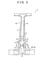
- FIG 2 is a side view of the center pillar structure shown in FIG 1 .
- the center pillar structure 1 of a vehicle such as an automobile, includes a center pillar 10.
- the center pillar 10 includes an outer panel 15, an inner panel 16, an outer reinforcement 2 and hinge reinforcements 13 and 14.
- the outer panel 15 and the inner panel 16 extend from a rocker to a roof side rail.
- the outer reinforcement 2 and the hinge reinforcements 13 and 14 are arranged in an internal space defined by the outer panel 15 and the inner panel 16.
- the outer panel 15 may be regarded as an outer shell member according to the aspect of the invention.
- the inner panel 16 may be regarded as an outer shell member according to the aspect of the invention.
- the outer reinforcement 2 may be regarded as a reinforcement member according to the aspect of the invention.
- the outer reinforcement 2 is formed so that high-tensile steel plates are jointed at a laser welding seam 3 as a boundary.
- the lower end portion of the outer reinforcement 2 is connected to the rocker, and the upper end portion of the outer reinforcement 2 is connected to the roof side rail.
- the strength of the lower high-tensile steel plate with respect to the laser welding seam 3 is lower than the strength of the upper high-tensile steel plate with respect to the laser welding seam 3 in such a manner that, for example, the thickness of the lower high-tensile steel plate is made thinner. That is, in the outer reinforcement 2, the portion on the lower side of the laser welding seam 3 is weaker than the portion on the upper side of the laser welding seam 3.
- the outer reinforcement 2 has beads 11 and 12 such that a pair of outer edge lines 2c formed by an outer wall 2a and a pair of side walls 2b are cut out.
- the beads 11 are located below the laser welding seam 3, and the beads 12 are located above the laser welding seam 3.
- the center pillar 10 has a weak portion 17 and a weak portion 18.
- the weak portion 17 is implemented by the beads 11.
- the weak portion 18 is implemented by the beads 12.
- the beads 11 and 12 may be regarded as weakened portions in the reinforcement member according to the aspect of the invention.
- the weak portion 17 may be regarded as a first weak portion according to the aspect of the invention.
- the weak portion 18 may be regarded as a second weak portion according to the aspect of the invention.
- a lower hinge 4 for a door is attached to a portion between the beads 11 and the beads 12, and an upper hinge 5 for the door is attached to a portion on the upper side of the beads 12. That is, the center pillar structure 1 includes the lower hinge 4, which is a protrusion between the weak portion 17 and the weak portion 18, and the protrusion protrudes outward from the center pillar 10 in the vehicle width direction.
- the hinge reinforcement 13 is arranged on the inner side of the outer reinforcement 2 in correspondence with a portion of the outer reinforcement 2, to which the lower hinge 4 is attached.
- the hinge reinforcement 14 is arranged on the inner side of the outer reinforcement 2 so as to extend from a portion of the outer reinforcement 2, to which the upper hinge 5 is attached, to an upper end portion of the outer reinforcement 2.
- the laser welding seam 3 is located between the portion, to which the lower hinge 4 is attached, and the beads 12; however, the laser welding seam 3 may be located between the portion, to which the lower hinge 4 is attached, and the beads 11.
- the graph with projections and depressions at the right side in FIG. 3 shows a strength distribution of the center pillar structure 1.
- the strength of the center pillar 10 is locally low at the weak portion 17 and at the weak portion 18. Therefore, when the vehicle is hit on the side, the center pillar 10 bends at the weak portion 17 and at the weak portion 18, and therefore the vehicle colliding advances substantially horizontally. This can reduce the bending moment generated in the center pillar 10 due to the advancement of the colliding vehicle, so it is possible to control deformation of the center pillar 10 in the event of a side collision while ensuring the strength of the center pillar 10.
- the strength of the center pillar 10 is varied by a large amount between the upper side and the lower side with respect to the lower end portion of the hinge reinforcement 14. This can remarkably localize a decrease in strength of the upper weak portion 18.
- the weak portion 17 and the weak portion 18 are implemented by the beads 11 and beads 12 of the outer reinforcement 2, so it is possible to easily and reliably provide the center pillar 10 with the weak portion 17 and the weak portion 18.
- the strength is minimal at the weak portion 17 and at the weak portion 18; however, the strength does not need to be minimal as long as the strength is locally low at the weak portion 17 and at the weak portion 18.
- the lower hinge 4 or an assumed load input region (acting portion at which external force is assumed to act on the center pillar 10 from the outer side in the vehicle width direction) may be located at a ground height of 400 mm to 500 mm. This is based on the bumper height of a typical vehicle. Alternatively, the lower hinge 4 or the assumed load input region may be located at a height that at least partially or entirely falls within the bumper height of the host vehicle.
- Table 1 GROUND HEIGHT (mm) MOST DESIRABLE RANGE MINIMUM MAXIMUM UPPER WEAK PORTION 18 500 TO 550 500 600 LOWER HINGE 4 OR ASSUMED LOAD INPUT REGION 400 TO 500 300 600 LOWER WEAK PORTION 17 350 TO 400 300 400
- the assumed load input region is a region in which a load acts from an object that is assumed to collide at the time of design, and may be, for example, a region corresponding to the bumper height.
- the weak portion 17 and the weak portion 18 may be located in the middle of the assumed load input region or so as to place the entire assumed load input region in between from above and below.
- the ratio of the "distance between the upper weak portion 18 and the lower hinge 4" to the "distance between the lower weak portion 17 and the lower hinge 4" may be a range from 1:1 to 2:1.
- 1:1 it is possible to reliably deform the portion between the weak portion 17 and the weak portion 18 so as to be substantially parallel to the vertical direction when the vehicle is hit on the side.
- 2:1 the bending point approaches the middle portion of the center pillar 10 without significantly losing the parallelism between the vertical direction and the portion between the weak portion 17 and the weak portion 18.
- the lower hinge 4 which is a protrusion that protrudes outward from the center pillar 10 in the vehicle width direction between the weak portion 17 and the weak portion 18, will be described.
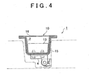
- FIG. 4 is a cross-sectional view of the center pillar structure 1, taken along the line IV-IV in FIG 2 .
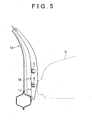
- FIG 5 is a front view of the center pillar structure 1 shown in FIG 1 .
- the lower hinge 4 protrudes outward from the center pillar 10 in the vehicle width direction between the weak portion 17 and the weak portion 18. Therefore, it is possible to easily concentrate a load on the portion between the weak portion 17 and the weak portion 18 in the initial stage of a collision with an object, such as the other vehicle V, and, as a result, it is possible to deform that portion desirably.
- the hinge reinforcement 13 is arranged on the inner side of the outer reinforcement 2 in correspondence with a portion of the outer reinforcement 2, to which the lower hinge 4 is attached. By doing so, it is possible to relatively increase the strength of the portion between the weak portion 17 and the weak portion 18 as compared with the strength of the weak portion 17 or the strength of the weak portion 18.
- the thickness of the high-tensile steel plate is, for example, varied between above and below the laser welding seam 3 to increase the weakness of the portion on the lower side of the laser welding seam 3 as compared with the portion on the upper side of the laser welding seam 3.
- the outer reinforcement 2 has the beads 11 and the beads 12. The beads 11 are located below the laser welding seam 3. The beads 12 are located above the laser welding seam 3. Thus, the strength of the weak portion 17 formed below the laser welding seam 3 is lower than the weak portion 18 formed above the laser welding seam 3.
- the strength of the lower weak portion 17 may be decreased as compared with the strength of the upper weak portion 18.
- the center pillar 10 bends at the lower weak portion 17 in the initial stage in which the other vehicle V (that is the vehicle colliding) collides with the side of the host vehicle as shown in FIG 6A , and, thereafter, the center pillar 10 bends at the upper weak portion 18 as shown in FIG 6B . Therefore, the other vehicle V advances substantially horizontally, and the portion between the weak portion 17 and the weak portion 18 deforms to be substantially parallel to the vertical direction. Thus, it is possible to reduce the bending moment generated in the center pillar 10 due to advancement of the other vehicle V.
- the strength of the upper weak portion 18 may be decreased as compared with the strength of the lower weak portion 17, or the strength of the upper weak portion 18 may be equivalent to the strength of the lower weak portion 17.
- FIG 7 is a cross-sectional view of a center pillar structure that has the load input member 19.
- FIG 8 is a perspective view of the center pillar structure that has the load input member 19.
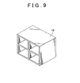
- FIG 9 is a perspective view of the load input member 19.
- the load input member 19 is arranged in a front door 31 so as to face the lower weak portion 17 in the vehicle width direction.
- the load input member 19 is, for example, made of resin and has a block shape.
- the load input member 19 is hollowed for reduction in weight.
- the strength of the load input member 19 is higher than the strength of the outer reinforcement 2, and is lower than the bonding strength between the rocker and the outer reinforcement.
- the load concentrates on the lower hinge 4 and then the load input member 19 facilitates a local load to be input to the weak portion 17.
- the center pillar 10 to initially bend at the lower weak portion 17 and subsequently bend at the upper weak portion 18.
- the other vehicle V advances substantially horizontally, and the portion between the weak portion 17 and the weak portion 18 deforms to be substantially parallel to the vertical direction.
- the load input member 19 may be arranged in correspondence with at least one of the weak portion 17 and the weak portion 18.
- the strength of the load input member 19 arranged in correspondence with the upper weak portion 18 and the strength of the load input member 19 arranged in correspondence with the lower weak portion 7 are varied to thereby making it possible to control local loads input respectively to the weak portion 17 and the weak portion 18.
- the load input member 19 may be arranged in a rear door 32.
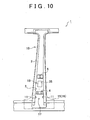
- FIG 10 is a side view of a center pillar structure that has the weak portion implemented by the harness fitting hole 35.
- FIG 11 is a cross-sectional view of the center pillar structure that has the weak portion implemented by the harness fitting hole.
- the harness fitting hole 35 is formed in the center pillar 10 between the portion to which the lower hinge 4 is attached and the portion to which the upper hinge 5 is attached.
- a harness 34 is attached to the harness fitting hole 35 and holds a wire 33 associated with a power window, a door lock, and the like. In this way, the upper weak portion 18 may be implemented by the harness fitting hole 35 instead of the beads 12.
- harness fitting hole 35 is formed on the lower side with respect to the portion of the center pillar 10, to which the lower hinge 4 is attached, and the lower weak portion 17 is implemented by the harness fitting hole 35 instead of the beads 11.
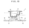
- FIG 12 is a side view of a center pillar structure that has door beams having end portions arranged in correspondence with the weak portions.
- FIG 13 is a cross-sectional view of the center pillar structure that has the door beams having the end portions arranged in correspondence with the weak portions.
- a rear end portion 36a of a front door beam 36 is arranged in the front door 31 so as to face the lower weak portion 17 in the vehicle width direction
- a front end portion 37a of a rear door beam 37 is arranged in the rear door 32 so as to face the upper weak portion 18 in the vehicle width direction.
- the door beams 36 and 37 are reinforcement members for absorbing energy when the vehicle is hit on the side.
- the load concentrates on the lower hinge 4 and then the rear end portion 36a of the front door beam 36 facilitates a local load to be input to the lower weak portion 17, while the front end portion 37a of the rear door beam 37 facilitates a local load to be input to the upper weak portion 18.
- the other vehicle V collides with the middle of the front door 31 or the middle of the rear door 37 with an offset frontward or rearward from the center pillar 10, it is possible to reliably bend the center pillar 10 at the weak portion 17 and at the weak portion 18.
- the rear end portion 36a of the front door beam 36 is arranged in correspondence with the upper weak portion 18, and the front end portion 37a of the rear door beam 37 is arranged in correspondence with the lower weak portion 17.
- the rear end portion 36a of the front door beam 36 or the front end portion 37a of the rear door beam 37 may be arranged in correspondence with at least one of the weak portion 17 and the weak portion 18.
- the rear end portion 36a of the front door beam 36 or the front end portion 37a of the rear door beam 37, which is arranged in correspondence with the lower weak portion 17, may be located at a height equivalent to that of the lower weak portion 17 or may be located in an assumed load input region that is set slightly above the lower weak portion 17.
- the portion between the weak portion 17 and the weak portion 18 deforms to be substantially parallel to the vertical direction when the vehicle is hit on the side, for example, it is possible to prevent a situation that the center pillar bends only at the portion corresponding to the lower weak portion 17 and then that portion protrudes into a cabin of the vehicle.
- the center pillar bends only at the portion corresponding to the lower weak portion 17 when the center pillar 10 bends both at the weak portion 17 and at the weak portion 18 and then the portion between the weak portion 17 and the weak portion 18 deforms to be substantially parallel to the vertical direction, it is possible to suppress a speed at which the deformed portion of the center pillar 10 is displaced.
- the center pillar 10 may be configured so that, when external force acts on the portion between the weak portion 17 and the weak portion 18 from the outside in the vehicle width direction, a displacement of the portion between the weak portion 17 and the weak portion 18 is maximal.
- the center pillar 10 may be configured so that the portion between the weak portion 17 and the weak portion 18 deforms into a curved shape having a tangent line that is substantially parallel to the vertical direction.
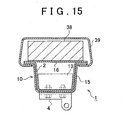
- shock-absorbing member 38 arranged in correspondence with the portion between the weak portion 17 and the weak portion 18 will be described.
- FIG 15 is a cross-sectional view of a center pillar structure that has the shock-absorbing member 38.
- a pillar garnish 39 is attached onto the inner side (cabin side) of the center pillar 10.
- the shock-absorbing member 38 is, for example, made of urethane foam.
- the shock-absorbing member 38 is arranged in the pillar garnish 39 so as to face the portion between the weak portion 17 and the weak portion 18 in the vehicle width direction. Thus, even when the portion between the weak portion 17 and the weak portion 18 deforms into the cabin at the time when the vehicle is hit on the side, the shock may be reduced.
- shock-absorbing member 38 may be attached to a seat side surface, or the like, as long as the shock-absorbing member 38 is arranged on the inner side with respect to the center pillar 10 in correspondence with the portion between the weak portion 17 and the weak portion 18.
- FIG 16 is a perspective view of a center pillar structure, which is a second embodiment of the pillar structure of a vehicle according to the invention.
- FIG 17 is a front view of the center pillar structure shown in FIG 16 .
- the center pillar structure 1 includes an outer reinforcement 2.
- the outer reinforcement 2 is formed so that high-tensile steel plates are jointed via a laser welding seam 3.
- the upper end portion of the outer reinforcement 2 is connected to a roof side rail, and the lower end portion of the outer reinforcement 2 is connected to a rocker.
- An outward projected non-quenched portion 6 is formed in the outer reinforcement 2 between a portion to which a lower hinge 4 of a door is attached and a portion to which an upper hinge 5 of the door is attached.
- an outward projected non-quenched portion 7 is formed in the outer reinforcement 2 between the portion to which the lower hinge 4 is attached and a portion connected to the rocker.
- the non-quenched portions 6 and 7 are formed in the outer reinforcement 2 at the upper and lower portions with respect to the portion to which the lower hinge 4 is attached, while quenched portions 8 are formed in the outer reinforcement 2 at portions other than the non-quenched portions 6 and 7.
- portions corresponding to the weak portion 17 and the weak portion 18 according to the first embodiment are implemented respectively by the non-quenched portion 7 and the non-quenched portion 6.
- the center pillar structure 1 by forming the non-quenched portions 6 and 7 in the outer reinforcement 2 at the upper and lower portions with respect to the portion to which the lower hinge 4 is attached, it is possible to easily form buckling points (bending points) in the event of a side collision. Then, when the vehicle is hit on the side, the outer reinforcement 2 bends at the upper and lower portions with respect to the portion to which the lower hinge 4 is attached, so it is possible to reduce the bending moment generated in the outer reinforcement 2 due to advancement of the other vehicle. Thus, with the center pillar structure 1, it is possible to control deformation of the center pillar in the event of a side collision while ensuring the strength of the center pillar.
- FIG 18A shows an outer reinforcement 102 in which one point, that is, an upper portion with respect to the portion to which the lower hinge 4 is attached, becomes a buckling point B when the vehicle is hit on the side.
- FIG 18B shows the outer reinforcement 2 according to the second embodiment in which two points, that is, the upper and lower portions with respect to the portion to which the lower hinge 4 is attached, become buckling points B when the vehicle is hit on the side. Note that, in the outer reinforcement 2 shown in FIG. 18B , the strength of the non-quenched portion 7 is lower than the strength of the non-quenched portion 6.
- FIG 19A to FIG 19C respectively show the deformed outer reinforcement 102 shown in FIG. 18A , a bending moment diagram and shear force diagram of the deformed outer reinforcement 102 shown in FIG 18A .
- FIG 20A, FIG. 20B and FIG. 20C respectively show the deformed outer reinforcement 2 shown in FIG 18B , a bending moment diagram and shear force diagram of the deformed outer reinforcement 2 shown in FIG 18B .
- M B indicates a moment applied to the buckling point B.
- Fy indicates an impact reaction force generated by the outer reinforcement
- Fy B is a reaction force generated by bending within Fy.
- the outer reinforcement 102 generates an impact reaction force in the event of a side collision by a relatively large bending and a relatively small axial force
- the outer reinforcement 2 generates an impact reaction force in the event of a side collision by a relatively small bending and a relatively large axial force
- a moment input to a beltline portion reduces. Therefore, it is possible to reduce reinforcement at the beltline portion, and it is possible to reduce the weight and cost of the center pillar.
- a high-tensile steel plate 2a which will be the outer reinforcement 2
- the high-tensile steel plate 2a is stamped and heated with a cope (die) 21 and a drag (die) 22 for hot stamping.
- gaps between the cope 21 and drag 22 and the high-tensile steel plate 2a are appropriately controlled so that gaps between the cope 21 and portions 6a and 7a corresponding to the non-quenched portions 6 and 7 in the high-tensile steel plate 2a are narrower than gaps between the cope 21 and portions 8a corresponding to the quenched portions 8 in the high-tensile steel plate 2a.
- the cope 21 is brought into close contact with the portions 6a and 7a corresponding to the non-quenched portions 6 and 7.
- cooling water is supplied through cooling water supply holes 21a, formed in the cope 21, into the gaps between the cope 21 and the portions 8a corresponding to the quenched portions 8.
- the cope 21 is in close contact with the portions 6a and 7a corresponding to the non-quenched portions 6 and 7. Therefore, as shown in FIG. 22 , cooling water does not flow to the portions 6a and 7a corresponding to the non-quenched portions 6 and 7, and cooling water flows only to the portions 8a corresponding to the quenched portions 8.
- the thus formed outer reinforcement 2 is used to manufacture the center pillar structure 1.
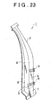
- FIG 23 is a perspective view of a center pillar structure, which is a third embodiment of the pillar structure of a vehicle according to the invention.
- the center pillar structure 1 according to the third embodiment differs from the above described center pillar structure 1 according to the second embodiment in that non-quenched portions 6 and 7 are not projected in the outer reinforcement 2.
- the center pillar structure 1 is manufactured as follows. That is, as shown in FIG. 24 and FIG 25 , a high-tensile steel plate 2a, which will be the outer reinforcement 2, is prepared, and then the high-tensile steel plate 2a is stamped and heated with a cope (die) 21 and a drag (die) 22 for hot stamping. Subsequently, cooling water is supplied through cooling water supply holes 21a into gaps between the cope 21 and the portions 8a corresponding to the quenched portions 8. The cooling water supply holes 21a are formed in the cope 21 at portions in correspondence with the quenched portions 8. The supplied cooling water is drained outside through cooling water drain holes 21b.
- the cooling water drain holes 21b are formed in the cope 21 at portions in correspondence with boundaries between the quenched portions 8 and the non-quenched portions 6 and 7. Thus, no cooling water flows to the portions 6a and 7a corresponding to the non-quenched portions 6 and 7, and cooling water flows only to the portions 8a corresponding to the quenched portions 8. Hence, only the portions 8a are quenched by rapid cooling. Then, the thus formed outer reinforcement 2 is used to manufacture the center pillar structure 1.
- a pair of outer edge line portions respectively have the beads 11 and 12.
- the number of beads 12 formed in the upper portion with respect to the portion to which the lower hinge 4 is attached is larger than the number of beads 11 formed in the lower portion with respect to the portion to which the lower hinge 4 is attached, while, on the other hand, the thickness and material are varied between the lower portion and the upper portion.
- the strength of the member of the upper portion with respect to the laser welding seam 3 is higher than the strength of the member of the lower portion with respect to the laser welding seam 3. In this case, it is not necessary to joint high-tensile steel plates at the laser welding seam 3 as a boundary in order to form the outer reinforcement 2.
- a bead 12 is formed to extend over a pair of outer edge line portions, and beads 11 are formed respectively at the pair of outer edge line portions.
- a lower end portion of the hinge reinforcement 14 that extends along the inner surface of the outer wall of the outer reinforcement 2 is elongated to the inner side of the bead 12.
- the pillar structure of a vehicle according to the aspect of the invention is not necessarily limited to a center pillar structure, and the number of weak portions of the pillar is not limited to two.
- the weak portion may be implemented not only by the shape of a member that constitutes the pillar but also by changing the material of a member that constitutes the pillar, adjusting the thickness of the material of the member, a degree to which the material of the member is quenched, the plastic effect of the material of the member, or the like.
Landscapes
- Engineering & Computer Science (AREA)
- Chemical & Material Sciences (AREA)
- Combustion & Propulsion (AREA)
- Transportation (AREA)
- Mechanical Engineering (AREA)
- Body Structure For Vehicles (AREA)
Claims (22)
- Säulenstruktur eines Fahrzeugs, mit:einer Säule, die einen ersten Schwächungsabschnitt (17) und einen zweiten Schwächungsabschnitt (18) aufweist, wobeider zweite Schwächungsabschnitt (18) sich über dem ersten Schwächungsabschnitt (17) befindet, wobeidie Festigkeit des ersten Schwächungsabschnitts (17) niedriger als die Festigkeit des zweiten Schwächungsabschnitts (18) ist; dadurch gekennzeichnet, dassdie Säule eine Außenschale (15, 16), die sich von einem Schweller zu einer dachseitigen Schiene des Fahrzeugs erstreckt, und ein Verstärkungselement (2) aufweist, das in der Außenschale (15, 16) angeordnet ist; undder erste Schwächungsabschnitt (17) und der zweite Schwächungsabschnitt (18) jeweils durch geschwächte Abschnitte (11, 12) in dem Verstärkungselement (2) implementiert sind, wobeiein Lasteinbringungselement (19) in Übereinstimmung mit zumindest einem von dem ersten Schwächungsabschnitt (17) und dem zweiten Schwächungsabschnitt (18) angeordnet ist, unddie Festigkeit des Lasteinbringungselements (19) höher als die Festigkeit des Verstärkungselements (2) und niedriger als die Fügefestigkeit zwischen dem Schweller und dem Verstärkungselement (2) ist.
- Säulenstruktur eines Fahrzeugs gemäß Anspruch 1, wobei die Säule zwischen dem ersten Schwächungsabschnitt (17) und dem zweiten Schwächungsabschnitt (18) einen Vorsprung hat, der von der Säule in einer Fahrzeugbreitenrichtung nach Außen vorsteht.
- Säulenstruktur eines Fahrzeugs gemäß Anspruch 1 oder 2, wobei
der erste Schwächungsabschnitt (17) sich unter einem Wirkungsabschnitt befindet, von dem angenommen wird, dass an ihm eine externe Kraft an der Säule von einer Außenseite in einer Richtung der Breite des Fahrzeugs wirkt, und
der erste Schwächungsabschnitt (18) sich über dem Wirkungsabschnitt befindet. - Säulenstruktur eines Fahrzeugs gemäß einem der Ansprüche 1 bis 3, wobei die geschwächten Abschnitte (11, 12) in dem Verstärkungselement (2) durch Sicken implementiert sind, die in dem Verstärkungselement (2) ausgebildet sind.
- Säulenstruktur eines Fahrzeugs gemäß Anspruch 4, wobei eine Differenz der Festigkeit zwischen dem ersten Schwächungsabschnitt (17) und dem zweiten Schwächungsabschnitt (18) durch zumindest eines aus der Abmessung der Sicken, der Anzahl der Sicken und der Dicke des Verstärkungselements (2), in dem die Sicken ausgebildet sind, implementiert ist.
- Säulenstruktur eines Fahrzeugs gemäß einem der Ansprüche 1 bis 3, wobei jeder der geschwächten Abschnitte (11, 12) in dem Verstärkungselement (2) zumindest durch eine Sicke und/oder ein Kabelstrangeinsatzloch (35), das in dem Verstärkungselement (2) ausgebildet ist, implementiert sind.
- Säulenstruktur eines Fahrzeugs gemäß einem der Ansprüche 1 bis 6, wobei
das Verstärkungselement (2) Abschnitte hat, an denen ein erstes Gelenk (4) und ein zweites Gelenk (5) einer Tür angebracht sind;
das erste Gelenk (4) zwischen dem ersten Schwächungsabschnitt (17) und dem zweiten Schwächungsabschnitt (18) angebracht ist; und
das zweite Gelenk (5) über dem zweiten Schwächungsabschnitt (18) angebracht ist. - Säulenstruktur eines Fahrzeugs gemäß Anspruch 7, wobei das Verhältnis aus einem Abstand zwischen dem zweiten Schwächungsabschnitt (18) und dem ersten Gelenk (4) zu einem Abstand zwischen dem ersten Schwächungsabschnitt (17) und dem ersten Gelenk (4) in einem Bereich von 1:1 bis 2:1 liegt.
- Säulenstruktur eines Fahrzeugs gemäß Anspruch 7 oder 8, wobei zumindest eines von dem ersten Gelenk (4) und dem zweiten Gelenk (5) in einer Fahrzeugbreitenrichtung des Fahrzeugs vorragt.
- Säulenstruktur eines Fahrzeugs gemäß einem der Ansprüche 1 bis 9, wobei ein Endabschnitt eines Türbalkens (36, 37) in Übereinstimmung mit zumindest einem von dem ersten Schwächungsabschnitt (17) und dem zweiten Schwächungsabschnitt (18) angeordnet ist.
- Säulenstruktur eines Fahrzeugs gemäß einem der Ansprüche 1 bis 10, wobei zumindest einer von dem ersten Schwächungsabschnitt und dem zweiten Schwächungsabschnitt ein Lasteinbringungselement (19) aufweist, das einer Last erleichtert, in den zumindest einen von dem ersten Schwächungsabschnitt (17) und dem zweiten Schwächungsabschnitt (18) eingebracht zu werden, wenn an dem Fahrzeug von einer Außenseite in einer Fahrzeugbreitenrichtung eine externe Kraft wirkt.
- Säulenstruktur eines Fahrzeugs gemäß einem der Ansprüche 1 bis 11, wobei ein stoßabsorbierendes Element (38) zwischen dem ersten Schwächungsabschnitt (17) und dem zweiten Schwächungsabschnitt (18) angebracht ist.
- Säulenstruktur eines Fahrzeugs gemäß einem der Ansprüche 1 bis 12, wobei dann, wenn an einem Abschnitt zwischen dem ersten Schwächungsabschnitt (17) und dem zweiten Schwächungsabschnitt (18) von einer Außenseite in einer Fahrzeugbreitenrichtung eine externe Kraft wirkt, eine Verschiebung des Abschnitts zwischen dem ersten Schwächungsabschnitt (17) und dem zweiten Schwächungsabschnitt (18) maximal ist.
- Säulenstruktur eines Fahrzeugs gemäß einem der Ansprüche 1 bis 13, wobei
die Säule eine Außenschale (15, 16) und ein Verstärkungselement (2) aufweist, das in der Außenschale (15, 16) angeordnet ist; und
das Verstärkungselement (2) nicht abgeschreckte Abschnitte (6, 7), die mit Bezug auf einen Abschnitt, an dem ein unteres Gelenk (4) einer Tür angebracht ist, an einem oberen Abschnitt (6) und einem unteren Abschnitt (7) ausgebildet sind, und abgeschreckte Abschnitte (8) hat, die an Abschnitten ausgebildet sind, die sich von dem oberen Abschnitt (6) und dem unteren Abschnitt (7) unterscheiden, wobei der erste Schwächungsabschnitt (17) und der zweite Schwächungsabschnitt (18) durch die nicht abgeschreckten Abschnitte (6, 7) implementiert sind. - Säulenstruktur eines Fahrzeugs gemäß einem der Ansprüche 1 bis 13, wobei
die Säule eine Außenschale (15, 16) und ein Verstärkungselement (2) aufweist, das in der Außenschale (15, 16) angeordnet ist; und
der erste Schwächungsabschnitt (17) und der zweite Schwächungsabschnitt (18) durch nicht abgeschreckte Abschnitte (6, 7) implementiert sind. - Säulenstruktur eines Fahrzeugs gemäß Anspruch 14 oder 15, wobei die nicht abgeschreckten Abschnitte (6, 7) in dem Verstärkungselement (2) so ausgebildet sind, dass sie in Richtung der Außenschale (15, 16) vorragen.
- Säulenstruktur eines Fahrzeugs gemäß einem der Ansprüche 14 bis 16, wobei dann, wenn das Verstärkungselement (2) abgeschreckt wird, ein Kühlwasserstrom zu Abschnitten des erwärmten Verstärkungselements (2), die den abgeschreckten Abschnitten (8) entsprechen, verglichen mit einem Kühlwasserstrom zu Abschnitten des erwärmten Verstärkungselements (2), die den nicht abgeschreckten Abschnitten (6, 7) entsprechen, vergrößert ist.
- Säulenstruktur eines Fahrzeugs gemäß Anspruch 17, wobei die den nicht abgeschreckten Abschnitten (6, 7) entsprechenden Abschnitte so ausgebildet sind, dass sie vorragen, wobei Spalten zwischen einer Heißprägeform und den den nicht abgeschreckten Abschnitten (6, 7) entsprechenden Abschnitten enger als Spalten zwischen der Form und den den abgeschreckten Abschnitten (8) entsprechenden Abschnitten sind, und dann der Kühlwasserstrom zu den den abgeschreckten Abschnitten (8) entsprechenden Abschnitten verglichen mit dem Kühlwasserstrom zu den den nicht abgeschreckten Abschnitten (6, 7) entsprechenden Abschnitten vergrößert wird.
- Säulenstruktur eines Fahrzeugs gemäß Anspruch 7, wobei Kühlwasserzuführlöcher in einer Heißprägeform in Übereinstimmung mit den abgeschreckten Abschnitten (8) ausgebildet sind, Kühlwasserablasslöcher in der Form in Übereinstimmung mit Grenzen zwischen den abgeschreckten Abschnitten (8) und den nicht abgeschreckten Abschnitten (6, 7) ausgebildet sind, und dann der Kühlwasserstrom zu den den abgeschreckten Abschnitten (8) entsprechenden Abschnitten verglichen mit dem Kühlwasserstrom zu den den nicht abgeschreckten Abschnitten (6, 7) entsprechenden Abschnitten vergrößert wird.
- Säulenstruktur eines Fahrzeugs gemäß einem der Ansprüche 1 bis 19, wobei die Bodenhöhe des ersten Schwächungsabschnitts (17) und die Bodenhöhe des zweiten Schwächungsabschnitts (18) auf Grundlage einer Höhe bestimmt sind, von der angenommen wird, dass dort die externe Kraft von einer Außenseite in einer Fahrzeugbreitenrichtung an dem Fahrzeug wirkt.
- Säulenstruktur eines Fahrzeugs gemäß Anspruch 20, wobei die Bodenhöhe des ersten Schwächungsabschnitts (17) und die Bodenhöhe des zweiten Schwächungsabschnitts (18) auf Grundlage einer Stoßfängerhöhe eines Fahrzeugs bestimmt sind.
- Verfahren zum Herstellen einer Säulenstruktur, die eine Säule mit einer sich von einem Schweller zu einer dachseitigen Schiene des Fahrzeugs erstreckenden Außenschale (15, 16) und einem in der Außenschale (15, 16) angeordneten Verstärkungselement (2) aufweist, mit:beim Abschrecken des Verstärkungselements (2) Vergrößern des Kühlwasserstroms zu Abschnitten des erwärmten Verstärkungselements (2), die sich in dem erwärmten Verstärkungselement (2)von einem oberen Abschnitt (6) und einem unteren Abschnitt (7) mit Bezug auf einen Abschnitt, an dem ein unteres Gelenk (4) einer Tür angebracht ist, unterscheiden, und zwar verglichen mit dem oberen Abschnitt (6) und dem unteren Abschnitt (7); undVersehen der Säule mit einem ersten Schwächungsabschnitt (17) und einem zweiten Schwächungsabschnitt (18), der sich über dem ersten Schwächungsabschnitt (17) befindet, derart, dass der obere Abschnitt (6) und der untere Abschnitt (7) als nicht abgeschreckte Abschnitte (6, 7) ausgebildet sind, und die sich von dem oberen Abschnitt (6) und dem unteren Abschnitt (7) unterscheidenden Abschnitte als abgeschreckte Abschnitte (8) ausgebildet sind; gekennzeichnet durchFestlegen der Festigkeit des ersten Schwächungsabschnitts (17) niedriger als die Festigkeit des zweiten Schwächungsabschnitts (18), wobei der erste Schwächungsabschnitt (17) und der zweite Schwächungsabschnitt (18) jeweils durch geschwächte Abschnitte (11, 12) in dem Verstärkungselement (2) implementiert sind,Anordnen eines Lasteinbringungselements (19) in Übereinstimmung mit zumindest einem von dem ersten Schwächungsabschnitt (17) und dem zweiten Schwächungsabschnitt (18), wobei die Festigkeit des Lasteinbringungselements (19) höher als die Festigkeit des Verstärkungselements (2) und niedriger als die Fügefestigkeit zwischen dem Schweller und dem Verstärkungselement (2) ist.
Applications Claiming Priority (2)
| Application Number | Priority Date | Filing Date | Title |
|---|---|---|---|
| JP2008183100A JP5131065B2 (ja) | 2008-07-14 | 2008-07-14 | 車両のピラー構造及びその製造方法。 |
| PCT/IB2009/006139 WO2010007481A1 (en) | 2008-07-14 | 2009-07-02 | Pillar structure of vehicle and method for manufacturing the same |
Publications (2)
| Publication Number | Publication Date |
|---|---|
| EP2310246A1 EP2310246A1 (de) | 2011-04-20 |
| EP2310246B1 true EP2310246B1 (de) | 2014-09-24 |
Family
ID=41152366
Family Applications (1)
| Application Number | Title | Priority Date | Filing Date |
|---|---|---|---|
| EP09785979.7A Active EP2310246B1 (de) | 2008-07-14 | 2009-07-02 | Säulenstruktur eines fahrzeugs und herstellungsverfahren dafür |
Country Status (5)
| Country | Link |
|---|---|
| US (1) | US8480163B2 (de) |
| EP (1) | EP2310246B1 (de) |
| JP (1) | JP5131065B2 (de) |
| CN (1) | CN102099239B (de) |
| WO (1) | WO2010007481A1 (de) |
Cited By (2)
| Publication number | Priority date | Publication date | Assignee | Title |
|---|---|---|---|---|
| FR3118751A1 (fr) | 2021-01-13 | 2022-07-15 | Psa Automobiles Sa | Véhicule à structure à élément à raideur variable |
| FR3141132A1 (fr) | 2022-10-19 | 2024-04-26 | Psa Automobiles Sa | Renfort de pied central et pied central pour véhicule automobile. |
Families Citing this family (73)
| Publication number | Priority date | Publication date | Assignee | Title |
|---|---|---|---|---|
| SE533528C2 (sv) * | 2009-12-13 | 2010-10-19 | Gestamp Hardtech Ab | B-stolpe för fordon |
| JP5478314B2 (ja) * | 2010-03-23 | 2014-04-23 | 本田技研工業株式会社 | 車体側部構造 |
| JP5460402B2 (ja) * | 2010-03-23 | 2014-04-02 | 本田技研工業株式会社 | 車体側部構造 |
| JP5478313B2 (ja) * | 2010-03-23 | 2014-04-23 | 本田技研工業株式会社 | 車体側部構造 |
| JP5478312B2 (ja) * | 2010-03-23 | 2014-04-23 | 本田技研工業株式会社 | 車体側部構造 |
| JP5585166B2 (ja) * | 2010-03-30 | 2014-09-10 | マツダ株式会社 | 樹脂構造体を内蔵したセンタピラー構造 |
| JP5459029B2 (ja) * | 2010-04-08 | 2014-04-02 | トヨタ自動車株式会社 | 車両用のピラー構造および車両用ピラー製造方法 |
| JP5484175B2 (ja) * | 2010-04-23 | 2014-05-07 | 本田技研工業株式会社 | 車両のセンターピラー構造 |
| IT1400618B1 (it) * | 2010-05-12 | 2013-06-14 | Sistemi Sospensioni Spa | Elemento strutturale in materiale composito, particolarmente per sospensione di veicolo |
| JP5506551B2 (ja) * | 2010-06-03 | 2014-05-28 | ユニプレス株式会社 | 自動車車体のピラー構造 |
| WO2012026028A1 (ja) * | 2010-08-26 | 2012-03-01 | トヨタ自動車株式会社 | 車体のロッカ構造 |
| JP2012101648A (ja) * | 2010-11-09 | 2012-05-31 | Toyota Motor Corp | 車両の骨格構造、骨格補強構造、ピラー構造及び部品製造方法 |
| JP5533594B2 (ja) * | 2010-11-25 | 2014-06-25 | トヨタ自動車株式会社 | 車両のピラー構造 |
| JP5691460B2 (ja) * | 2010-12-07 | 2015-04-01 | トヨタ自動車株式会社 | 車両のピラー構造 |
| US8757709B2 (en) * | 2010-12-20 | 2014-06-24 | Tesla Motors, Inc. | Reinforced B-pillar assembly with reinforced rocker joint |
| US20140191539A1 (en) * | 2011-05-26 | 2014-07-10 | Toyota Jidosha Kabushiki Kaisha | Method of forming header extension, and vehicle structure |
| JP2013023038A (ja) * | 2011-07-19 | 2013-02-04 | Toyota Motor East Japan Inc | 車両用センターピラー |
| FR2979608B1 (fr) * | 2011-09-05 | 2013-10-04 | Peugeot Citroen Automobiles Sa | Dispositif de renfort lateral a couches de renfort pour un montant a mi longueur d'un cote de caisse de vehicule automobile |
| WO2013038505A1 (ja) * | 2011-09-13 | 2013-03-21 | トヨタ自動車株式会社 | 車両のピラー構造 |
| DE102011054909A1 (de) * | 2011-10-28 | 2013-05-02 | Benteler Automobiltechnik Gmbh | Verfahren zur Herstellung eines Kraftfahrzeugbauteils sowie nach dem Verfahren hergestelltes Kraftfahrzeugbauteil |
| US9045164B2 (en) * | 2011-11-30 | 2015-06-02 | Toyota Jidosha Kabushiki Kaisha | Vehicle body structure |
| DE102011120519A1 (de) * | 2011-12-08 | 2013-06-13 | GM Global Technology Operations LLC (n. d. Gesetzen des Staates Delaware) | Verstärkung für eine Fahrzeugsäule, insbesodnere die B-Säule eines Fahrzeuges |
| JP6178546B2 (ja) * | 2012-04-27 | 2017-08-09 | 日産自動車株式会社 | 車体構造 |
| WO2013161611A1 (ja) * | 2012-04-27 | 2013-10-31 | 日産自動車株式会社 | 対側突荷重伝達構造 |
| WO2013177377A1 (en) * | 2012-05-24 | 2013-11-28 | Zephyros, Inc. | Vehicle body structure cut zones |
| SE1200459A1 (sv) * | 2012-07-25 | 2013-04-23 | Gestamp Hardtech Ab | B-stolpe och sätt att tillverka sådan |
| DE102012015463B4 (de) * | 2012-08-07 | 2020-09-17 | Volkswagen Aktiengesellschaft | Karosseriesäule, insbesondere B-Säule für ein Fahrzeug |
| MX368291B (es) | 2012-09-06 | 2019-09-26 | Etxetar Sa | Procedimiento y sistema para el endurecimiento por laser de una superficie de una pieza de trabajo. |
| JP6136233B2 (ja) * | 2012-12-19 | 2017-05-31 | スズキ株式会社 | 車両のセンターピラー下部車体構造 |
| US9090287B2 (en) * | 2013-01-14 | 2015-07-28 | GM Global Technology Operations LLC | Vehicle structural support member reinforced with ultra high strength laminate |
| DE102013002421B4 (de) * | 2013-02-11 | 2017-05-11 | Audi Ag | B-Säule, für ein Kraftfahrzeug |
| DE202013004133U1 (de) * | 2013-05-02 | 2014-08-04 | Gm Global Technology Operations, Llc | Hinterwagen für ein Kraftfahrzeug mit einer Verstärkungsstruktur |
| JP6285675B2 (ja) * | 2013-09-19 | 2018-02-28 | アイシン高丘株式会社 | センターピラー補強部材 |
| WO2015049949A1 (ja) * | 2013-10-01 | 2015-04-09 | 本田技研工業株式会社 | 自動車の車体構造 |
| US10023237B2 (en) * | 2013-11-15 | 2018-07-17 | Autotech Engineering A.I.E. | Beam for producing a metal framework |
| DE102014201198B3 (de) * | 2014-01-23 | 2015-05-28 | Volkswagen Aktiengesellschaft | Karosseriesäule, insbesondere B-Säule für ein Fahrzeug |
| JP6213314B2 (ja) * | 2014-03-07 | 2017-10-18 | 新日鐵住金株式会社 | ドアインパクトビームおよびその製造法 |
| JP2014141256A (ja) * | 2014-04-10 | 2014-08-07 | Toyota Motor Corp | ピラー構造及びピラー構造製造方法 |
| JP5975058B2 (ja) * | 2014-04-15 | 2016-08-23 | トヨタ自動車株式会社 | ピラー構造及び車両側部構造 |
| DE102014209816A1 (de) * | 2014-05-22 | 2015-11-26 | Bayerische Motoren Werke Aktiengesellschaft | Türsäule einer Kraftwagenkarosserie in Schalenbauweise |
| DE102014112740A1 (de) * | 2014-09-04 | 2016-03-10 | Voestalpine Stahl Gmbh | B-Säule |
| JP6029639B2 (ja) * | 2014-11-11 | 2016-11-24 | 本田技研工業株式会社 | 車体側部構造 |
| CN104477249A (zh) * | 2014-12-03 | 2015-04-01 | 力帆实业(集团)股份有限公司 | 汽车的b柱加强组件 |
| DE102014018862B4 (de) * | 2014-12-16 | 2018-08-30 | Audi Ag | Fahrzeugsäule für eine Fahrzeugkarosserie |
| US9630652B2 (en) * | 2015-03-04 | 2017-04-25 | Fca Us Llc | Vehicle pillar reinforcement construction for side impact |
| JP6226335B2 (ja) | 2015-03-16 | 2017-11-08 | 本田技研工業株式会社 | 車体構造 |
| US10864603B2 (en) | 2015-03-17 | 2020-12-15 | Ikergune A.I.E. | Method and system for heat treatment of sheet metal |
| JP6476035B2 (ja) * | 2015-03-31 | 2019-02-27 | 株式会社Subaru | 車両のピラー構造 |
| US10464511B2 (en) * | 2015-07-08 | 2019-11-05 | Nippon Steel Corporation | Bumper reinforcement and vehicle including the same |
| US9676420B2 (en) * | 2015-09-02 | 2017-06-13 | Tesla, Inc. | B-pillar deformation mode |
| CN105350865A (zh) * | 2015-11-06 | 2016-02-24 | 美环五金门部件(平湖)有限公司 | 一种门框中档 |
| JP6493184B2 (ja) * | 2015-12-04 | 2019-04-03 | トヨタ自動車株式会社 | 車両側部構造 |
| DE102015225689B3 (de) * | 2015-12-17 | 2017-01-26 | Volkswagen Aktiengesellschaft | Karosseriesäule, insbesondere B-Säule, für ein Fahrzeug |
| US10807648B2 (en) | 2016-01-22 | 2020-10-20 | Futaba Industrial Co., Ltd. | Frame |
| FR3051760B1 (fr) * | 2016-05-24 | 2018-06-15 | Renault S.A.S | Structure de pied milieu pourvu d'un element de renfort |
| US9969434B2 (en) * | 2016-09-01 | 2018-05-15 | Ford Global Technologies, Llc | Vehicle body B-pillar assembly with cell member |
| US9994258B2 (en) * | 2016-10-07 | 2018-06-12 | Hyundai Motor Company | Vehicle body side reinforcement assembly of vehicle |
| JP6555303B2 (ja) * | 2017-07-28 | 2019-08-07 | マツダ株式会社 | 車両の側部車体構造 |
| JP6966297B2 (ja) * | 2017-11-20 | 2021-11-10 | 株式会社Subaru | 車体構造 |
| US10479411B2 (en) | 2018-01-31 | 2019-11-19 | Toyota Motor Engineering & Manufacturing North America, Inc. | Structurally reinforced vehicle body |
| KR102598951B1 (ko) * | 2018-09-12 | 2023-11-07 | 현대자동차주식회사 | 필러 보강구조 |
| JP7137133B2 (ja) * | 2018-09-27 | 2022-09-14 | マツダ株式会社 | 車両の側部車体構造 |
| US10953929B2 (en) | 2018-11-09 | 2021-03-23 | Honda Motor Co., Ltd. | Shear plate for a side sill |
| FR3092069B1 (fr) * | 2019-01-28 | 2025-04-11 | Psa Automobiles Sa | Renfort de pilier pour véhicule automobile comportant un biseau |
| JP7236303B2 (ja) * | 2019-03-27 | 2023-03-09 | 日産自動車株式会社 | 車体のピラー構造 |
| JP7172867B2 (ja) * | 2019-06-14 | 2022-11-16 | マツダ株式会社 | 側部車体構造 |
| JP7367388B2 (ja) * | 2019-08-26 | 2023-10-24 | マツダ株式会社 | 車両の側部車体構造 |
| US12030105B2 (en) * | 2019-09-25 | 2024-07-09 | Nippon Steel Corporation | Structural member, structural member manufacturing method, and structural member manufacturing device |
| US11208151B2 (en) | 2020-01-24 | 2021-12-28 | Toyota Motor Engineering & Manufacturing North America, Inc. | Pillar apparatus for use with vehicles |
| CN112249166A (zh) * | 2020-09-14 | 2021-01-22 | 阿尔特汽车技术股份有限公司 | 一种b柱下铰链加强板组件 |
| CN114435481B (zh) * | 2020-11-02 | 2023-04-25 | 本田技研工业(中国)投资有限公司 | 一种用于车辆的b柱 |
| FR3121115A1 (fr) * | 2021-03-23 | 2022-09-30 | Psa Automobiles Sa | Véhicule à structure à élément à déformation variable |
| JP7824093B2 (ja) * | 2022-02-24 | 2026-03-04 | 株式会社Subaru | 車体構造部材及び車体構造 |
Family Cites Families (27)
| Publication number | Priority date | Publication date | Assignee | Title |
|---|---|---|---|---|
| JPH0794311B2 (ja) | 1988-10-11 | 1995-10-11 | 三菱電機株式会社 | エレベータ表示装置 |
| JP3173539B2 (ja) * | 1993-08-30 | 2001-06-04 | 日産自動車株式会社 | 自動車のセンタピラー補強構造 |
| JP3335781B2 (ja) * | 1994-08-31 | 2002-10-21 | 富士重工業株式会社 | 車両のセンタピラー部全周閉断面構造 |
| JP3216479B2 (ja) | 1995-05-16 | 2001-10-09 | トヨタ自動車株式会社 | 自動車のセンタピラー補強構造 |
| JPH09175428A (ja) | 1995-12-25 | 1997-07-08 | Toyota Autom Loom Works Ltd | 自動車のセンタピラー構造 |
| JP3305952B2 (ja) | 1996-06-28 | 2002-07-24 | トヨタ自動車株式会社 | センターピラーリーンフォースの高周波焼入れ強化方法 |
| KR20010049950A (ko) * | 1999-08-05 | 2001-06-15 | 제임스 이. 미러 | 차체의 프레임구조 |
| JP3876279B2 (ja) * | 2001-05-24 | 2007-01-31 | ダイハツ工業株式会社 | 自動車のピラー補強構造 |
| WO2003046230A1 (fr) | 2001-11-27 | 2003-06-05 | Kikuchi Co., Ltd. | Moulage a la presse, procede de trempe haute frequence associe et systeme de trempe haute frequence associe |
| JP4208044B2 (ja) * | 2001-11-27 | 2009-01-14 | 菊池プレス工業株式会社 | 車体用センターピラー |
| JP2003239018A (ja) * | 2001-12-13 | 2003-08-27 | Kikuchi Co Ltd | プレス成形品の焼入れ方法及び焼入れ装置 |
| JP3674586B2 (ja) | 2002-01-16 | 2005-07-20 | 日産自動車株式会社 | 車体フレームの補強構造 |
| JP2003312536A (ja) | 2002-04-23 | 2003-11-06 | Nissan Motor Co Ltd | 車体骨格フレームの補強構造 |
| JP2005067582A (ja) | 2003-08-01 | 2005-03-17 | Nissan Motor Co Ltd | 車体構造 |
| JP4151527B2 (ja) | 2003-09-03 | 2008-09-17 | 日産自動車株式会社 | 車体側面構造 |
| JP4470494B2 (ja) * | 2004-01-13 | 2010-06-02 | 日産自動車株式会社 | 車体構造 |
| JP4449758B2 (ja) * | 2005-01-21 | 2010-04-14 | 三菱自動車工業株式会社 | 車体構造 |
| US7152914B2 (en) * | 2005-03-21 | 2006-12-26 | Gm Global Technology Operations, Inc. | Vehicle center pillar structure |
| JP4483843B2 (ja) * | 2006-09-11 | 2010-06-16 | 日産自動車株式会社 | 車体骨格フレームの補強構造 |
| JP4917932B2 (ja) * | 2007-03-20 | 2012-04-18 | 本田技研工業株式会社 | 車体側部構造 |
| JP4445522B2 (ja) * | 2007-06-20 | 2010-04-07 | 豊田鉄工株式会社 | 車両用センターピラーの補強部材 |
| BRPI0805842A2 (pt) * | 2007-10-17 | 2011-08-30 | Toyota Motor Co Ltd | artigo moldado para membro estrutural do corpo de veìculo |
| SE0702513L (sv) * | 2007-11-15 | 2009-04-28 | Gestamp Hardtech Ab | B-stolpe till fordon |
| JP5104264B2 (ja) * | 2007-12-07 | 2012-12-19 | トヨタ車体株式会社 | 自動車のピラー構造 |
| JP5407372B2 (ja) * | 2009-01-30 | 2014-02-05 | マツダ株式会社 | 車両の側部車体構造 |
| JP5327614B2 (ja) * | 2009-03-31 | 2013-10-30 | スズキ株式会社 | 車体のピラー構造 |
| KR101163872B1 (ko) * | 2010-04-29 | 2012-07-09 | 기아자동차주식회사 | 3도어 차량의 센터 필라 어셈블리 |
-
2008
- 2008-07-14 JP JP2008183100A patent/JP5131065B2/ja active Active
-
2009
- 2009-07-02 US US13/003,497 patent/US8480163B2/en active Active
- 2009-07-02 EP EP09785979.7A patent/EP2310246B1/de active Active
- 2009-07-02 WO PCT/IB2009/006139 patent/WO2010007481A1/en not_active Ceased
- 2009-07-02 CN CN200980127698.0A patent/CN102099239B/zh active Active
Cited By (3)
| Publication number | Priority date | Publication date | Assignee | Title |
|---|---|---|---|---|
| FR3118751A1 (fr) | 2021-01-13 | 2022-07-15 | Psa Automobiles Sa | Véhicule à structure à élément à raideur variable |
| WO2022152988A1 (fr) | 2021-01-13 | 2022-07-21 | Psa Automobiles Sa | Véhicule à structure à élément à raideur variable |
| FR3141132A1 (fr) | 2022-10-19 | 2024-04-26 | Psa Automobiles Sa | Renfort de pied central et pied central pour véhicule automobile. |
Also Published As
| Publication number | Publication date |
|---|---|
| JP5131065B2 (ja) | 2013-01-30 |
| US20110133515A1 (en) | 2011-06-09 |
| US8480163B2 (en) | 2013-07-09 |
| EP2310246A1 (de) | 2011-04-20 |
| WO2010007481A1 (en) | 2010-01-21 |
| CN102099239B (zh) | 2014-01-22 |
| CN102099239A (zh) | 2011-06-15 |
| JP2010018254A (ja) | 2010-01-28 |
Similar Documents
| Publication | Publication Date | Title |
|---|---|---|
| EP2310246B1 (de) | Säulenstruktur eines fahrzeugs und herstellungsverfahren dafür | |
| JP5407372B2 (ja) | 車両の側部車体構造 | |
| EP2509849B2 (de) | B-säule für ein fahrzeug | |
| JP4286884B2 (ja) | 自動車の車体構造 | |
| US7887122B2 (en) | One-piece shotgun with impact energy absorber | |
| US10967909B2 (en) | Side vehicle-body structure of vehicle | |
| JP5407367B2 (ja) | 車両の側部車体構造 | |
| KR20090118086A (ko) | 측면 충돌 성능을 강화시킨 자동차용 도어 | |
| WO2016140744A1 (en) | Vehicle pillar reinforcement construction for side impact | |
| EP4190646A1 (de) | Strukturelement für eine automobilkarosserie | |
| JP2010195187A (ja) | 車両用衝突補強材 | |
| US20250128767A1 (en) | Vehicle body structure, and method for designing vehicle body structure | |
| US20230001870A1 (en) | Vehicle beam component and assembly | |
| JP4668007B2 (ja) | 自動車のセンターピラー補強構造 | |
| JP5054467B2 (ja) | 車両の側部車体構造 | |
| JP2007055414A (ja) | 車両用エネルギ吸収ビーム及び車両用ドア構造 | |
| EP4190645B1 (de) | Strukturelement einer fahrzeugkarosserie | |
| US11554813B2 (en) | Front pillar upper structure | |
| CN118683630A (zh) | 车身下部结构 | |
| JP2024004063A (ja) | 車両のセンタピラー |
Legal Events
| Date | Code | Title | Description |
|---|---|---|---|
| PUAI | Public reference made under article 153(3) epc to a published international application that has entered the european phase |
Free format text: ORIGINAL CODE: 0009012 |
|
| 17P | Request for examination filed |
Effective date: 20110105 |
|
| AK | Designated contracting states |
Kind code of ref document: A1 Designated state(s): AT BE BG CH CY CZ DE DK EE ES FI FR GB GR HR HU IE IS IT LI LT LU LV MC MK MT NL NO PL PT RO SE SI SK SM TR |
|
| AX | Request for extension of the european patent |
Extension state: AL BA RS |
|
| DAX | Request for extension of the european patent (deleted) | ||
| 17Q | First examination report despatched |
Effective date: 20120510 |
|
| RAP1 | Party data changed (applicant data changed or rights of an application transferred) |
Owner name: TOYOTA JIDOSHA KABUSHIKI KAISHA |
|
| GRAP | Despatch of communication of intention to grant a patent |
Free format text: ORIGINAL CODE: EPIDOSNIGR1 |
|
| INTG | Intention to grant announced |
Effective date: 20140411 |
|
| GRAS | Grant fee paid |
Free format text: ORIGINAL CODE: EPIDOSNIGR3 |
|
| GRAA | (expected) grant |
Free format text: ORIGINAL CODE: 0009210 |
|
| AK | Designated contracting states |
Kind code of ref document: B1 Designated state(s): AT BE BG CH CY CZ DE DK EE ES FI FR GB GR HR HU IE IS IT LI LT LU LV MC MK MT NL NO PL PT RO SE SI SK SM TR |
|
| REG | Reference to a national code |
Ref country code: GB Ref legal event code: FG4D |
|
| REG | Reference to a national code |
Ref country code: CH Ref legal event code: EP |
|
| REG | Reference to a national code |
Ref country code: AT Ref legal event code: REF Ref document number: 688478 Country of ref document: AT Kind code of ref document: T Effective date: 20141015 |
|
| REG | Reference to a national code |
Ref country code: IE Ref legal event code: FG4D |
|
| REG | Reference to a national code |
Ref country code: DE Ref legal event code: R096 Ref document number: 602009026848 Country of ref document: DE Effective date: 20141106 |
|
| PG25 | Lapsed in a contracting state [announced via postgrant information from national office to epo] |
Ref country code: LT Free format text: LAPSE BECAUSE OF FAILURE TO SUBMIT A TRANSLATION OF THE DESCRIPTION OR TO PAY THE FEE WITHIN THE PRESCRIBED TIME-LIMIT Effective date: 20140924 Ref country code: SE Free format text: LAPSE BECAUSE OF FAILURE TO SUBMIT A TRANSLATION OF THE DESCRIPTION OR TO PAY THE FEE WITHIN THE PRESCRIBED TIME-LIMIT Effective date: 20140924 Ref country code: NO Free format text: LAPSE BECAUSE OF FAILURE TO SUBMIT A TRANSLATION OF THE DESCRIPTION OR TO PAY THE FEE WITHIN THE PRESCRIBED TIME-LIMIT Effective date: 20141224 Ref country code: GR Free format text: LAPSE BECAUSE OF FAILURE TO SUBMIT A TRANSLATION OF THE DESCRIPTION OR TO PAY THE FEE WITHIN THE PRESCRIBED TIME-LIMIT Effective date: 20141225 Ref country code: FI Free format text: LAPSE BECAUSE OF FAILURE TO SUBMIT A TRANSLATION OF THE DESCRIPTION OR TO PAY THE FEE WITHIN THE PRESCRIBED TIME-LIMIT Effective date: 20140924 |
|
| REG | Reference to a national code |
Ref country code: LT Ref legal event code: MG4D Ref country code: NL Ref legal event code: VDEP Effective date: 20140924 |
|
| PG25 | Lapsed in a contracting state [announced via postgrant information from national office to epo] |
Ref country code: LV Free format text: LAPSE BECAUSE OF FAILURE TO SUBMIT A TRANSLATION OF THE DESCRIPTION OR TO PAY THE FEE WITHIN THE PRESCRIBED TIME-LIMIT Effective date: 20140924 Ref country code: HR Free format text: LAPSE BECAUSE OF FAILURE TO SUBMIT A TRANSLATION OF THE DESCRIPTION OR TO PAY THE FEE WITHIN THE PRESCRIBED TIME-LIMIT Effective date: 20140924 Ref country code: CY Free format text: LAPSE BECAUSE OF FAILURE TO SUBMIT A TRANSLATION OF THE DESCRIPTION OR TO PAY THE FEE WITHIN THE PRESCRIBED TIME-LIMIT Effective date: 20140924 |
|
| REG | Reference to a national code |
Ref country code: AT Ref legal event code: MK05 Ref document number: 688478 Country of ref document: AT Kind code of ref document: T Effective date: 20140924 |
|
| PG25 | Lapsed in a contracting state [announced via postgrant information from national office to epo] |
Ref country code: NL Free format text: LAPSE BECAUSE OF FAILURE TO SUBMIT A TRANSLATION OF THE DESCRIPTION OR TO PAY THE FEE WITHIN THE PRESCRIBED TIME-LIMIT Effective date: 20140924 |
|
| REG | Reference to a national code |
Ref country code: DE Ref legal event code: R084 Ref document number: 602009026848 Country of ref document: DE |
|
| PG25 | Lapsed in a contracting state [announced via postgrant information from national office to epo] |
Ref country code: RO Free format text: LAPSE BECAUSE OF FAILURE TO SUBMIT A TRANSLATION OF THE DESCRIPTION OR TO PAY THE FEE WITHIN THE PRESCRIBED TIME-LIMIT Effective date: 20140924 Ref country code: PT Free format text: LAPSE BECAUSE OF FAILURE TO SUBMIT A TRANSLATION OF THE DESCRIPTION OR TO PAY THE FEE WITHIN THE PRESCRIBED TIME-LIMIT Effective date: 20150126 Ref country code: CZ Free format text: LAPSE BECAUSE OF FAILURE TO SUBMIT A TRANSLATION OF THE DESCRIPTION OR TO PAY THE FEE WITHIN THE PRESCRIBED TIME-LIMIT Effective date: 20140924 Ref country code: IS Free format text: LAPSE BECAUSE OF FAILURE TO SUBMIT A TRANSLATION OF THE DESCRIPTION OR TO PAY THE FEE WITHIN THE PRESCRIBED TIME-LIMIT Effective date: 20150124 Ref country code: ES Free format text: LAPSE BECAUSE OF FAILURE TO SUBMIT A TRANSLATION OF THE DESCRIPTION OR TO PAY THE FEE WITHIN THE PRESCRIBED TIME-LIMIT Effective date: 20140924 Ref country code: EE Free format text: LAPSE BECAUSE OF FAILURE TO SUBMIT A TRANSLATION OF THE DESCRIPTION OR TO PAY THE FEE WITHIN THE PRESCRIBED TIME-LIMIT Effective date: 20140924 Ref country code: SK Free format text: LAPSE BECAUSE OF FAILURE TO SUBMIT A TRANSLATION OF THE DESCRIPTION OR TO PAY THE FEE WITHIN THE PRESCRIBED TIME-LIMIT Effective date: 20140924 |
|
| REG | Reference to a national code |
Ref country code: GB Ref legal event code: 746 Effective date: 20150424 |
|
| PG25 | Lapsed in a contracting state [announced via postgrant information from national office to epo] |
Ref country code: AT Free format text: LAPSE BECAUSE OF FAILURE TO SUBMIT A TRANSLATION OF THE DESCRIPTION OR TO PAY THE FEE WITHIN THE PRESCRIBED TIME-LIMIT Effective date: 20140924 Ref country code: PL Free format text: LAPSE BECAUSE OF FAILURE TO SUBMIT A TRANSLATION OF THE DESCRIPTION OR TO PAY THE FEE WITHIN THE PRESCRIBED TIME-LIMIT Effective date: 20140924 |
|
| REG | Reference to a national code |
Ref country code: DE Ref legal event code: R084 Ref document number: 602009026848 Country of ref document: DE Effective date: 20150417 |
|
| REG | Reference to a national code |
Ref country code: DE Ref legal event code: R097 Ref document number: 602009026848 Country of ref document: DE |
|
| PG25 | Lapsed in a contracting state [announced via postgrant information from national office to epo] |
Ref country code: DK Free format text: LAPSE BECAUSE OF FAILURE TO SUBMIT A TRANSLATION OF THE DESCRIPTION OR TO PAY THE FEE WITHIN THE PRESCRIBED TIME-LIMIT Effective date: 20140924 |
|
| PLBE | No opposition filed within time limit |
Free format text: ORIGINAL CODE: 0009261 |
|
| STAA | Information on the status of an ep patent application or granted ep patent |
Free format text: STATUS: NO OPPOSITION FILED WITHIN TIME LIMIT |
|
| PG25 | Lapsed in a contracting state [announced via postgrant information from national office to epo] |
Ref country code: IT Free format text: LAPSE BECAUSE OF FAILURE TO SUBMIT A TRANSLATION OF THE DESCRIPTION OR TO PAY THE FEE WITHIN THE PRESCRIBED TIME-LIMIT Effective date: 20140924 |
|
| 26N | No opposition filed |
Effective date: 20150625 |
|
| PG25 | Lapsed in a contracting state [announced via postgrant information from national office to epo] |
Ref country code: SI Free format text: LAPSE BECAUSE OF FAILURE TO SUBMIT A TRANSLATION OF THE DESCRIPTION OR TO PAY THE FEE WITHIN THE PRESCRIBED TIME-LIMIT Effective date: 20140924 Ref country code: MC Free format text: LAPSE BECAUSE OF FAILURE TO SUBMIT A TRANSLATION OF THE DESCRIPTION OR TO PAY THE FEE WITHIN THE PRESCRIBED TIME-LIMIT Effective date: 20140924 |
|
| REG | Reference to a national code |
Ref country code: CH Ref legal event code: PL |
|
| PG25 | Lapsed in a contracting state [announced via postgrant information from national office to epo] |
Ref country code: LU Free format text: LAPSE BECAUSE OF FAILURE TO SUBMIT A TRANSLATION OF THE DESCRIPTION OR TO PAY THE FEE WITHIN THE PRESCRIBED TIME-LIMIT Effective date: 20150702 |
|
| REG | Reference to a national code |
Ref country code: IE Ref legal event code: MM4A |
|
| PG25 | Lapsed in a contracting state [announced via postgrant information from national office to epo] |
Ref country code: LI Free format text: LAPSE BECAUSE OF NON-PAYMENT OF DUE FEES Effective date: 20150731 Ref country code: CH Free format text: LAPSE BECAUSE OF NON-PAYMENT OF DUE FEES Effective date: 20150731 |
|
| REG | Reference to a national code |
Ref country code: FR Ref legal event code: PLFP Year of fee payment: 8 |
|
| PG25 | Lapsed in a contracting state [announced via postgrant information from national office to epo] |
Ref country code: IE Free format text: LAPSE BECAUSE OF NON-PAYMENT OF DUE FEES Effective date: 20150702 |
|
| PG25 | Lapsed in a contracting state [announced via postgrant information from national office to epo] |
Ref country code: MT Free format text: LAPSE BECAUSE OF FAILURE TO SUBMIT A TRANSLATION OF THE DESCRIPTION OR TO PAY THE FEE WITHIN THE PRESCRIBED TIME-LIMIT Effective date: 20140924 |
|
| PG25 | Lapsed in a contracting state [announced via postgrant information from national office to epo] |
Ref country code: SM Free format text: LAPSE BECAUSE OF FAILURE TO SUBMIT A TRANSLATION OF THE DESCRIPTION OR TO PAY THE FEE WITHIN THE PRESCRIBED TIME-LIMIT Effective date: 20140924 Ref country code: BG Free format text: LAPSE BECAUSE OF FAILURE TO SUBMIT A TRANSLATION OF THE DESCRIPTION OR TO PAY THE FEE WITHIN THE PRESCRIBED TIME-LIMIT Effective date: 20140924 Ref country code: HU Free format text: LAPSE BECAUSE OF FAILURE TO SUBMIT A TRANSLATION OF THE DESCRIPTION OR TO PAY THE FEE WITHIN THE PRESCRIBED TIME-LIMIT; INVALID AB INITIO Effective date: 20090702 |
|
| REG | Reference to a national code |
Ref country code: FR Ref legal event code: PLFP Year of fee payment: 9 |
|
| PG25 | Lapsed in a contracting state [announced via postgrant information from national office to epo] |
Ref country code: TR Free format text: LAPSE BECAUSE OF FAILURE TO SUBMIT A TRANSLATION OF THE DESCRIPTION OR TO PAY THE FEE WITHIN THE PRESCRIBED TIME-LIMIT Effective date: 20140924 |
|
| PG25 | Lapsed in a contracting state [announced via postgrant information from national office to epo] |
Ref country code: BE Free format text: LAPSE BECAUSE OF FAILURE TO SUBMIT A TRANSLATION OF THE DESCRIPTION OR TO PAY THE FEE WITHIN THE PRESCRIBED TIME-LIMIT Effective date: 20140924 |
|
| REG | Reference to a national code |
Ref country code: FR Ref legal event code: PLFP Year of fee payment: 10 |
|
| PG25 | Lapsed in a contracting state [announced via postgrant information from national office to epo] |
Ref country code: MK Free format text: LAPSE BECAUSE OF FAILURE TO SUBMIT A TRANSLATION OF THE DESCRIPTION OR TO PAY THE FEE WITHIN THE PRESCRIBED TIME-LIMIT Effective date: 20140924 |
|
| P01 | Opt-out of the competence of the unified patent court (upc) registered |
Effective date: 20230427 |
|
| PGFP | Annual fee paid to national office [announced via postgrant information from national office to epo] |
Ref country code: GB Payment date: 20250508 Year of fee payment: 17 |
|
| PGFP | Annual fee paid to national office [announced via postgrant information from national office to epo] |
Ref country code: FR Payment date: 20250508 Year of fee payment: 17 |
|
| PGFP | Annual fee paid to national office [announced via postgrant information from national office to epo] |
Ref country code: DE Payment date: 20250507 Year of fee payment: 17 |