EP1876029A1 - Thermotransferbildempfangspapier und verfahren zur herstellung von thermotransferbildempfangspapier - Google Patents
Thermotransferbildempfangspapier und verfahren zur herstellung von thermotransferbildempfangspapier Download PDFInfo
- Publication number
- EP1876029A1 EP1876029A1 EP06745520A EP06745520A EP1876029A1 EP 1876029 A1 EP1876029 A1 EP 1876029A1 EP 06745520 A EP06745520 A EP 06745520A EP 06745520 A EP06745520 A EP 06745520A EP 1876029 A1 EP1876029 A1 EP 1876029A1
- Authority
- EP
- European Patent Office
- Prior art keywords
- image receiving
- layer
- thermal transfer
- receiving layer
- resin
- Prior art date
- Legal status (The legal status is an assumption and is not a legal conclusion. Google has not performed a legal analysis and makes no representation as to the accuracy of the status listed.)
- Granted
Links
- 238000012546 transfer Methods 0.000 title claims abstract description 277
- 238000000034 method Methods 0.000 title claims abstract description 199
- 230000008569 process Effects 0.000 title claims abstract description 96
- 229920005989 resin Polymers 0.000 claims abstract description 240
- 239000011347 resin Substances 0.000 claims abstract description 240
- 229920001296 polysiloxane Polymers 0.000 claims abstract description 207
- 239000000758 substrate Substances 0.000 claims abstract description 96
- 239000011230 binding agent Substances 0.000 claims abstract description 35
- 238000009413 insulation Methods 0.000 claims description 181
- 239000000945 filler Substances 0.000 claims description 126
- 229920001225 polyester resin Polymers 0.000 claims description 85
- 239000004645 polyester resin Substances 0.000 claims description 85
- 229920005992 thermoplastic resin Polymers 0.000 claims description 84
- 239000002245 particle Substances 0.000 claims description 69
- 238000004519 manufacturing process Methods 0.000 claims description 66
- 238000010030 laminating Methods 0.000 claims description 33
- 238000009826 distribution Methods 0.000 claims description 31
- 238000011282 treatment Methods 0.000 claims description 29
- 229920002050 silicone resin Polymers 0.000 claims description 12
- 239000010419 fine particle Substances 0.000 claims description 10
- 238000003475 lamination Methods 0.000 claims description 5
- 238000007639 printing Methods 0.000 abstract description 16
- 239000010410 layer Substances 0.000 description 549
- -1 polysiloxane structure Polymers 0.000 description 61
- 230000000052 comparative effect Effects 0.000 description 41
- 239000000203 mixture Substances 0.000 description 36
- 239000000853 adhesive Substances 0.000 description 28
- 239000000975 dye Substances 0.000 description 28
- 125000000524 functional group Chemical group 0.000 description 28
- 230000001070 adhesive effect Effects 0.000 description 27
- 239000000123 paper Substances 0.000 description 27
- 239000003795 chemical substances by application Substances 0.000 description 26
- 229920001577 copolymer Polymers 0.000 description 21
- 229920002545 silicone oil Polymers 0.000 description 21
- 239000012790 adhesive layer Substances 0.000 description 20
- 239000000463 material Substances 0.000 description 20
- 239000011800 void material Substances 0.000 description 19
- LYCAIKOWRPUZTN-UHFFFAOYSA-N Ethylene glycol Chemical compound OCCO LYCAIKOWRPUZTN-UHFFFAOYSA-N 0.000 description 17
- 238000001125 extrusion Methods 0.000 description 16
- VTYYLEPIZMXCLO-UHFFFAOYSA-L Calcium carbonate Chemical compound [Ca+2].[O-]C([O-])=O VTYYLEPIZMXCLO-UHFFFAOYSA-L 0.000 description 14
- 229920000642 polymer Polymers 0.000 description 13
- 241000894007 species Species 0.000 description 13
- MTHSVFCYNBDYFN-UHFFFAOYSA-N diethylene glycol Chemical compound OCCOCCO MTHSVFCYNBDYFN-UHFFFAOYSA-N 0.000 description 12
- 150000001875 compounds Chemical class 0.000 description 11
- 239000003921 oil Substances 0.000 description 11
- 235000019198 oils Nutrition 0.000 description 11
- 239000002253 acid Substances 0.000 description 10
- 150000002148 esters Chemical class 0.000 description 10
- 239000007787 solid Substances 0.000 description 10
- NIXOWILDQLNWCW-UHFFFAOYSA-M Acrylate Chemical compound [O-]C(=O)C=C NIXOWILDQLNWCW-UHFFFAOYSA-M 0.000 description 9
- VYPSYNLAJGMNEJ-UHFFFAOYSA-N Silicium dioxide Chemical compound O=[Si]=O VYPSYNLAJGMNEJ-UHFFFAOYSA-N 0.000 description 9
- 230000008901 benefit Effects 0.000 description 9
- 229920000728 polyester Polymers 0.000 description 9
- 239000011241 protective layer Substances 0.000 description 9
- 230000035945 sensitivity Effects 0.000 description 9
- VGGSQFUCUMXWEO-UHFFFAOYSA-N Ethene Chemical compound C=C VGGSQFUCUMXWEO-UHFFFAOYSA-N 0.000 description 8
- 239000005977 Ethylene Substances 0.000 description 8
- 229920000297 Rayon Polymers 0.000 description 8
- PPBRXRYQALVLMV-UHFFFAOYSA-N Styrene Chemical compound C=CC1=CC=CC=C1 PPBRXRYQALVLMV-UHFFFAOYSA-N 0.000 description 8
- 239000003054 catalyst Substances 0.000 description 8
- 239000000470 constituent Substances 0.000 description 8
- 239000004014 plasticizer Substances 0.000 description 8
- 239000004925 Acrylic resin Substances 0.000 description 7
- 239000004952 Polyamide Substances 0.000 description 7
- 239000004721 Polyphenylene oxide Substances 0.000 description 7
- 229910000019 calcium carbonate Inorganic materials 0.000 description 7
- 235000010216 calcium carbonate Nutrition 0.000 description 7
- 229960003563 calcium carbonate Drugs 0.000 description 7
- 230000000694 effects Effects 0.000 description 7
- 239000012948 isocyanate Substances 0.000 description 7
- 229920002647 polyamide Polymers 0.000 description 7
- 229920000570 polyether Polymers 0.000 description 7
- 229920000139 polyethylene terephthalate Polymers 0.000 description 7
- 239000005020 polyethylene terephthalate Substances 0.000 description 7
- 239000011148 porous material Substances 0.000 description 7
- 229920002554 vinyl polymer Polymers 0.000 description 7
- 229920000178 Acrylic resin Polymers 0.000 description 6
- 239000004743 Polypropylene Substances 0.000 description 6
- KKEYFWRCBNTPAC-UHFFFAOYSA-N Terephthalic acid Chemical compound OC(=O)C1=CC=C(C(O)=O)C=C1 KKEYFWRCBNTPAC-UHFFFAOYSA-N 0.000 description 6
- XLOMVQKBTHCTTD-UHFFFAOYSA-N Zinc monoxide Chemical compound [Zn]=O XLOMVQKBTHCTTD-UHFFFAOYSA-N 0.000 description 6
- NIXOWILDQLNWCW-UHFFFAOYSA-N acrylic acid group Chemical group C(C=C)(=O)O NIXOWILDQLNWCW-UHFFFAOYSA-N 0.000 description 6
- TZCXTZWJZNENPQ-UHFFFAOYSA-L barium sulfate Chemical compound [Ba+2].[O-]S([O-])(=O)=O TZCXTZWJZNENPQ-UHFFFAOYSA-L 0.000 description 6
- 238000011156 evaluation Methods 0.000 description 6
- QQVIHTHCMHWDBS-UHFFFAOYSA-N isophthalic acid Chemical compound OC(=O)C1=CC=CC(C(O)=O)=C1 QQVIHTHCMHWDBS-UHFFFAOYSA-N 0.000 description 6
- 238000002844 melting Methods 0.000 description 6
- 125000002496 methyl group Chemical group [H]C([H])([H])* 0.000 description 6
- 229920001155 polypropylene Polymers 0.000 description 6
- 239000001993 wax Substances 0.000 description 6
- 239000002250 absorbent Substances 0.000 description 5
- 230000002745 absorbent Effects 0.000 description 5
- 125000001931 aliphatic group Chemical group 0.000 description 5
- 230000015572 biosynthetic process Effects 0.000 description 5
- 230000000740 bleeding effect Effects 0.000 description 5
- 238000009792 diffusion process Methods 0.000 description 5
- 230000007246 mechanism Effects 0.000 description 5
- 239000012766 organic filler Substances 0.000 description 5
- 239000000049 pigment Substances 0.000 description 5
- 229920005668 polycarbonate resin Polymers 0.000 description 5
- 239000004431 polycarbonate resin Substances 0.000 description 5
- 229920000098 polyolefin Polymers 0.000 description 5
- 229920005672 polyolefin resin Polymers 0.000 description 5
- 229920005990 polystyrene resin Polymers 0.000 description 5
- JHWNWJKBPDFINM-UHFFFAOYSA-N Laurolactam Chemical compound O=C1CCCCCCCCCCCN1 JHWNWJKBPDFINM-UHFFFAOYSA-N 0.000 description 4
- 229920003298 Nucrel® Polymers 0.000 description 4
- 229920000299 Nylon 12 Polymers 0.000 description 4
- 239000004698 Polyethylene Substances 0.000 description 4
- 239000004793 Polystyrene Substances 0.000 description 4
- XUIMIQQOPSSXEZ-UHFFFAOYSA-N Silicon Chemical compound [Si] XUIMIQQOPSSXEZ-UHFFFAOYSA-N 0.000 description 4
- GWEVSGVZZGPLCZ-UHFFFAOYSA-N Titan oxide Chemical compound O=[Ti]=O GWEVSGVZZGPLCZ-UHFFFAOYSA-N 0.000 description 4
- WERYXYBDKMZEQL-UHFFFAOYSA-N butane-1,4-diol Chemical compound OCCCCO WERYXYBDKMZEQL-UHFFFAOYSA-N 0.000 description 4
- 239000012461 cellulose resin Substances 0.000 description 4
- 230000008859 change Effects 0.000 description 4
- 239000004927 clay Substances 0.000 description 4
- 239000011248 coating agent Substances 0.000 description 4
- 238000000576 coating method Methods 0.000 description 4
- WGCNASOHLSPBMP-UHFFFAOYSA-N hydroxyacetaldehyde Natural products OCC=O WGCNASOHLSPBMP-UHFFFAOYSA-N 0.000 description 4
- 239000004611 light stabiliser Substances 0.000 description 4
- 230000008018 melting Effects 0.000 description 4
- SLCVBVWXLSEKPL-UHFFFAOYSA-N neopentyl glycol Chemical compound OCC(C)(C)CO SLCVBVWXLSEKPL-UHFFFAOYSA-N 0.000 description 4
- 229920001778 nylon Polymers 0.000 description 4
- 229920006122 polyamide resin Polymers 0.000 description 4
- 229920001707 polybutylene terephthalate Polymers 0.000 description 4
- 229920000573 polyethylene Polymers 0.000 description 4
- 229920002223 polystyrene Polymers 0.000 description 4
- 229910052710 silicon Inorganic materials 0.000 description 4
- 239000010703 silicon Substances 0.000 description 4
- 239000000377 silicon dioxide Substances 0.000 description 4
- 238000000859 sublimation Methods 0.000 description 4
- 230000008022 sublimation Effects 0.000 description 4
- 239000000126 substance Substances 0.000 description 4
- 230000008093 supporting effect Effects 0.000 description 4
- BFKJFAAPBSQJPD-UHFFFAOYSA-N tetrafluoroethene Chemical group FC(F)=C(F)F BFKJFAAPBSQJPD-UHFFFAOYSA-N 0.000 description 4
- 125000000954 2-hydroxyethyl group Chemical group [H]C([*])([H])C([H])([H])O[H] 0.000 description 3
- 239000005995 Aluminium silicate Substances 0.000 description 3
- OFOBLEOULBTSOW-UHFFFAOYSA-N Malonic acid Chemical compound OC(=O)CC(O)=O OFOBLEOULBTSOW-UHFFFAOYSA-N 0.000 description 3
- 239000004594 Masterbatch (MB) Substances 0.000 description 3
- 239000004677 Nylon Substances 0.000 description 3
- 229910019142 PO4 Inorganic materials 0.000 description 3
- 239000004372 Polyvinyl alcohol Substances 0.000 description 3
- 229920001328 Polyvinylidene chloride Polymers 0.000 description 3
- DNIAPMSPPWPWGF-UHFFFAOYSA-N Propylene glycol Chemical compound CC(O)CO DNIAPMSPPWPWGF-UHFFFAOYSA-N 0.000 description 3
- 239000011354 acetal resin Substances 0.000 description 3
- PNEYBMLMFCGWSK-UHFFFAOYSA-N aluminium oxide Inorganic materials [O-2].[O-2].[O-2].[Al+3].[Al+3] PNEYBMLMFCGWSK-UHFFFAOYSA-N 0.000 description 3
- 235000012211 aluminium silicate Nutrition 0.000 description 3
- 125000003118 aryl group Chemical group 0.000 description 3
- 229940092690 barium sulfate Drugs 0.000 description 3
- 125000000484 butyl group Chemical group [H]C([*])([H])C([H])([H])C([H])([H])C([H])([H])[H] 0.000 description 3
- 238000006243 chemical reaction Methods 0.000 description 3
- 239000003086 colorant Substances 0.000 description 3
- 239000002270 dispersing agent Substances 0.000 description 3
- 125000003700 epoxy group Chemical group 0.000 description 3
- 230000009477 glass transition Effects 0.000 description 3
- 229920001519 homopolymer Polymers 0.000 description 3
- 239000011256 inorganic filler Substances 0.000 description 3
- 229910003475 inorganic filler Inorganic materials 0.000 description 3
- NLYAJNPCOHFWQQ-UHFFFAOYSA-N kaolin Chemical compound O.O.O=[Al]O[Si](=O)O[Si](=O)O[Al]=O NLYAJNPCOHFWQQ-UHFFFAOYSA-N 0.000 description 3
- 238000005192 partition Methods 0.000 description 3
- 230000002093 peripheral effect Effects 0.000 description 3
- 239000010452 phosphate Substances 0.000 description 3
- 229920002492 poly(sulfone) Polymers 0.000 description 3
- 229920006324 polyoxymethylene Polymers 0.000 description 3
- 229920002451 polyvinyl alcohol Polymers 0.000 description 3
- 229920000915 polyvinyl chloride Polymers 0.000 description 3
- 239000004800 polyvinyl chloride Substances 0.000 description 3
- 239000005033 polyvinylidene chloride Substances 0.000 description 3
- 230000003405 preventing effect Effects 0.000 description 3
- 239000000243 solution Substances 0.000 description 3
- 229920003002 synthetic resin Polymers 0.000 description 3
- 239000000454 talc Substances 0.000 description 3
- 229910052623 talc Inorganic materials 0.000 description 3
- 235000012222 talc Nutrition 0.000 description 3
- 238000012360 testing method Methods 0.000 description 3
- OGIDPMRJRNCKJF-UHFFFAOYSA-N titanium oxide Inorganic materials [Ti]=O OGIDPMRJRNCKJF-UHFFFAOYSA-N 0.000 description 3
- 235000014692 zinc oxide Nutrition 0.000 description 3
- 239000011787 zinc oxide Substances 0.000 description 3
- 229960001296 zinc oxide Drugs 0.000 description 3
- FKTHNVSLHLHISI-UHFFFAOYSA-N 1,2-bis(isocyanatomethyl)benzene Chemical compound O=C=NCC1=CC=CC=C1CN=C=O FKTHNVSLHLHISI-UHFFFAOYSA-N 0.000 description 2
- SMZOUWXMTYCWNB-UHFFFAOYSA-N 2-(2-methoxy-5-methylphenyl)ethanamine Chemical compound COC1=CC=C(C)C=C1CCN SMZOUWXMTYCWNB-UHFFFAOYSA-N 0.000 description 2
- WSQZNZLOZXSBHA-UHFFFAOYSA-N 3,8-dioxabicyclo[8.2.2]tetradeca-1(12),10,13-triene-2,9-dione Chemical compound O=C1OCCCCOC(=O)C2=CC=C1C=C2 WSQZNZLOZXSBHA-UHFFFAOYSA-N 0.000 description 2
- NLHHRLWOUZZQLW-UHFFFAOYSA-N Acrylonitrile Chemical compound C=CC#N NLHHRLWOUZZQLW-UHFFFAOYSA-N 0.000 description 2
- 239000004593 Epoxy Substances 0.000 description 2
- 239000004716 Ethylene/acrylic acid copolymer Substances 0.000 description 2
- 239000005057 Hexamethylene diisocyanate Substances 0.000 description 2
- 229920000877 Melamine resin Polymers 0.000 description 2
- CERQOIWHTDAKMF-UHFFFAOYSA-N Methacrylic acid Chemical compound CC(=C)C(O)=O CERQOIWHTDAKMF-UHFFFAOYSA-N 0.000 description 2
- 229920002292 Nylon 6 Polymers 0.000 description 2
- 229920002302 Nylon 6,6 Polymers 0.000 description 2
- ATUOYWHBWRKTHZ-UHFFFAOYSA-N Propane Chemical class CCC ATUOYWHBWRKTHZ-UHFFFAOYSA-N 0.000 description 2
- ATJFFYVFTNAWJD-UHFFFAOYSA-N Tin Chemical compound [Sn] ATJFFYVFTNAWJD-UHFFFAOYSA-N 0.000 description 2
- 229910021536 Zeolite Inorganic materials 0.000 description 2
- UKLDJPRMSDWDSL-UHFFFAOYSA-L [dibutyl(dodecanoyloxy)stannyl] dodecanoate Chemical group CCCCCCCCCCCC(=O)O[Sn](CCCC)(CCCC)OC(=O)CCCCCCCCCCC UKLDJPRMSDWDSL-UHFFFAOYSA-L 0.000 description 2
- 230000002159 abnormal effect Effects 0.000 description 2
- DHKHKXVYLBGOIT-UHFFFAOYSA-N acetaldehyde Diethyl Acetal Natural products CCOC(C)OCC DHKHKXVYLBGOIT-UHFFFAOYSA-N 0.000 description 2
- 150000007513 acids Chemical class 0.000 description 2
- 239000000654 additive Substances 0.000 description 2
- 230000000996 additive effect Effects 0.000 description 2
- WNLRTRBMVRJNCN-UHFFFAOYSA-N adipic acid Chemical compound OC(=O)CCCCC(O)=O WNLRTRBMVRJNCN-UHFFFAOYSA-N 0.000 description 2
- 125000003277 amino group Chemical group 0.000 description 2
- 239000002216 antistatic agent Substances 0.000 description 2
- 229960005069 calcium Drugs 0.000 description 2
- 229910052791 calcium Inorganic materials 0.000 description 2
- VPKDCDLSJZCGKE-UHFFFAOYSA-N carbodiimide group Chemical group N=C=N VPKDCDLSJZCGKE-UHFFFAOYSA-N 0.000 description 2
- 235000019241 carbon black Nutrition 0.000 description 2
- 239000006229 carbon black Substances 0.000 description 2
- 229940105289 carbon black Drugs 0.000 description 2
- 125000003178 carboxy group Chemical group [H]OC(*)=O 0.000 description 2
- 229920002678 cellulose Polymers 0.000 description 2
- 239000001913 cellulose Substances 0.000 description 2
- 229920006026 co-polymeric resin Polymers 0.000 description 2
- 238000004132 cross linking Methods 0.000 description 2
- HNPSIPDUKPIQMN-UHFFFAOYSA-N dioxosilane;oxo(oxoalumanyloxy)alumane Chemical compound O=[Si]=O.O=[Al]O[Al]=O HNPSIPDUKPIQMN-UHFFFAOYSA-N 0.000 description 2
- 239000006185 dispersion Substances 0.000 description 2
- 239000008151 electrolyte solution Substances 0.000 description 2
- RTZKZFJDLAIYFH-UHFFFAOYSA-N ether Substances CCOCC RTZKZFJDLAIYFH-UHFFFAOYSA-N 0.000 description 2
- 239000005038 ethylene vinyl acetate Substances 0.000 description 2
- 238000004299 exfoliation Methods 0.000 description 2
- 238000007756 gravure coating Methods 0.000 description 2
- 238000010438 heat treatment Methods 0.000 description 2
- RRAMGCGOFNQTLD-UHFFFAOYSA-N hexamethylene diisocyanate Chemical compound O=C=NCCCCCCN=C=O RRAMGCGOFNQTLD-UHFFFAOYSA-N 0.000 description 2
- 230000006872 improvement Effects 0.000 description 2
- 239000004615 ingredient Substances 0.000 description 2
- 229920000554 ionomer Polymers 0.000 description 2
- 239000000314 lubricant Substances 0.000 description 2
- 239000000178 monomer Substances 0.000 description 2
- KYTZHLUVELPASH-UHFFFAOYSA-N naphthalene-1,2-dicarboxylic acid Chemical compound C1=CC=CC2=C(C(O)=O)C(C(=O)O)=CC=C21 KYTZHLUVELPASH-UHFFFAOYSA-N 0.000 description 2
- BDJRBEYXGGNYIS-UHFFFAOYSA-N nonanedioic acid Chemical compound OC(=O)CCCCCCCC(O)=O BDJRBEYXGGNYIS-UHFFFAOYSA-N 0.000 description 2
- 230000000704 physical effect Effects 0.000 description 2
- 229920001200 poly(ethylene-vinyl acetate) Polymers 0.000 description 2
- 229920002037 poly(vinyl butyral) polymer Polymers 0.000 description 2
- 229920000058 polyacrylate Polymers 0.000 description 2
- 229920001721 polyimide Polymers 0.000 description 2
- 229920000306 polymethylpentene Polymers 0.000 description 2
- 239000011116 polymethylpentene Substances 0.000 description 2
- 239000004814 polyurethane Substances 0.000 description 2
- 229920002635 polyurethane Polymers 0.000 description 2
- 239000000843 powder Substances 0.000 description 2
- 230000009257 reactivity Effects 0.000 description 2
- 229920006395 saturated elastomer Polymers 0.000 description 2
- CXMXRPHRNRROMY-UHFFFAOYSA-N sebacic acid Chemical compound OC(=O)CCCCCCCCC(O)=O CXMXRPHRNRROMY-UHFFFAOYSA-N 0.000 description 2
- 239000002356 single layer Substances 0.000 description 2
- 239000002904 solvent Substances 0.000 description 2
- 239000004094 surface-active agent Substances 0.000 description 2
- 239000000057 synthetic resin Substances 0.000 description 2
- 238000007669 thermal treatment Methods 0.000 description 2
- 229960005196 titanium dioxide Drugs 0.000 description 2
- VZCYOOQTPOCHFL-UHFFFAOYSA-N trans-butenedioic acid Natural products OC(=O)C=CC(O)=O VZCYOOQTPOCHFL-UHFFFAOYSA-N 0.000 description 2
- 239000002966 varnish Substances 0.000 description 2
- 125000000391 vinyl group Chemical group [H]C([*])=C([H])[H] 0.000 description 2
- XLYOFNOQVPJJNP-UHFFFAOYSA-N water Substances O XLYOFNOQVPJJNP-UHFFFAOYSA-N 0.000 description 2
- 239000012463 white pigment Substances 0.000 description 2
- 239000010457 zeolite Substances 0.000 description 2
- IMYZYCNQZDBZBQ-UHFFFAOYSA-N (+-)-8-(cis-3-octyl-oxiranyl)-octanoic acid Natural products CCCCCCCCC1OC1CCCCCCCC(O)=O IMYZYCNQZDBZBQ-UHFFFAOYSA-N 0.000 description 1
- MSWMMXSNEVDUKZ-UHFFFAOYSA-N 1,1,3-trimethyl-3-phenyl-2h-indene-4,5-dicarboxylic acid Chemical compound C1=CC(C(O)=O)=C(C(O)=O)C2=C1C(C)(C)CC2(C)C1=CC=CC=C1 MSWMMXSNEVDUKZ-UHFFFAOYSA-N 0.000 description 1
- VZXTWGWHSMCWGA-UHFFFAOYSA-N 1,3,5-triazine-2,4-diamine Chemical compound NC1=NC=NC(N)=N1 VZXTWGWHSMCWGA-UHFFFAOYSA-N 0.000 description 1
- KPAPHODVWOVUJL-UHFFFAOYSA-N 1-benzofuran;1h-indene Chemical compound C1=CC=C2CC=CC2=C1.C1=CC=C2OC=CC2=C1 KPAPHODVWOVUJL-UHFFFAOYSA-N 0.000 description 1
- VEORPZCZECFIRK-UHFFFAOYSA-N 3,3',5,5'-tetrabromobisphenol A Chemical class C=1C(Br)=C(O)C(Br)=CC=1C(C)(C)C1=CC(Br)=C(O)C(Br)=C1 VEORPZCZECFIRK-UHFFFAOYSA-N 0.000 description 1
- CWVGVVRNVAMUCO-UHFFFAOYSA-N 3,3,5,5-tetramethyl-4-phenylcyclohexane-1,1-dicarboxylic acid Chemical compound CC1(C)CC(C(O)=O)(C(O)=O)CC(C)(C)C1C1=CC=CC=C1 CWVGVVRNVAMUCO-UHFFFAOYSA-N 0.000 description 1
- BJLUCDZIWWSFIB-UHFFFAOYSA-N 5-tert-butylbenzene-1,3-dicarboxylic acid Chemical compound CC(C)(C)C1=CC(C(O)=O)=CC(C(O)=O)=C1 BJLUCDZIWWSFIB-UHFFFAOYSA-N 0.000 description 1
- GZVHEAJQGPRDLQ-UHFFFAOYSA-N 6-phenyl-1,3,5-triazine-2,4-diamine Chemical compound NC1=NC(N)=NC(C=2C=CC=CC=2)=N1 GZVHEAJQGPRDLQ-UHFFFAOYSA-N 0.000 description 1
- RSWGJHLUYNHPMX-UHFFFAOYSA-N Abietic-Saeure Natural products C12CCC(C(C)C)=CC2=CCC2C1(C)CCCC2(C)C(O)=O RSWGJHLUYNHPMX-UHFFFAOYSA-N 0.000 description 1
- QTBSBXVTEAMEQO-UHFFFAOYSA-M Acetate Chemical compound CC([O-])=O QTBSBXVTEAMEQO-UHFFFAOYSA-M 0.000 description 1
- HRPVXLWXLXDGHG-UHFFFAOYSA-N Acrylamide Chemical compound NC(=O)C=C HRPVXLWXLXDGHG-UHFFFAOYSA-N 0.000 description 1
- OYPRJOBELJOOCE-UHFFFAOYSA-N Calcium Chemical compound [Ca] OYPRJOBELJOOCE-UHFFFAOYSA-N 0.000 description 1
- 229920001747 Cellulose diacetate Polymers 0.000 description 1
- 229920003043 Cellulose fiber Polymers 0.000 description 1
- 229920000089 Cyclic olefin copolymer Polymers 0.000 description 1
- YCKRFDGAMUMZLT-UHFFFAOYSA-N Fluorine atom Chemical compound [F] YCKRFDGAMUMZLT-UHFFFAOYSA-N 0.000 description 1
- VZCYOOQTPOCHFL-OWOJBTEDSA-N Fumaric acid Natural products OC(=O)\C=C\C(O)=O VZCYOOQTPOCHFL-OWOJBTEDSA-N 0.000 description 1
- 239000013032 Hydrocarbon resin Substances 0.000 description 1
- UFHFLCQGNIYNRP-UHFFFAOYSA-N Hydrogen Chemical compound [H][H] UFHFLCQGNIYNRP-UHFFFAOYSA-N 0.000 description 1
- CERQOIWHTDAKMF-UHFFFAOYSA-M Methacrylate Chemical compound CC(=C)C([O-])=O CERQOIWHTDAKMF-UHFFFAOYSA-M 0.000 description 1
- OKKJLVBELUTLKV-UHFFFAOYSA-N Methanol Chemical group OC OKKJLVBELUTLKV-UHFFFAOYSA-N 0.000 description 1
- 229920000305 Nylon 6,10 Polymers 0.000 description 1
- 239000002033 PVDF binder Substances 0.000 description 1
- 239000004696 Poly ether ether ketone Substances 0.000 description 1
- 239000004695 Polyether sulfone Substances 0.000 description 1
- 239000004697 Polyetherimide Substances 0.000 description 1
- 239000002202 Polyethylene glycol Substances 0.000 description 1
- 239000004642 Polyimide Substances 0.000 description 1
- KHPCPRHQVVSZAH-HUOMCSJISA-N Rosin Natural products O(C/C=C/c1ccccc1)[C@H]1[C@H](O)[C@@H](O)[C@@H](O)[C@@H](CO)O1 KHPCPRHQVVSZAH-HUOMCSJISA-N 0.000 description 1
- 229920001807 Urea-formaldehyde Polymers 0.000 description 1
- BZHJMEDXRYGGRV-UHFFFAOYSA-N Vinyl chloride Chemical compound ClC=C BZHJMEDXRYGGRV-UHFFFAOYSA-N 0.000 description 1
- 229920002433 Vinyl chloride-vinyl acetate copolymer Polymers 0.000 description 1
- XMUZQOKACOLCSS-UHFFFAOYSA-N [2-(hydroxymethyl)phenyl]methanol Chemical compound OCC1=CC=CC=C1CO XMUZQOKACOLCSS-UHFFFAOYSA-N 0.000 description 1
- YIMQCDZDWXUDCA-UHFFFAOYSA-N [4-(hydroxymethyl)cyclohexyl]methanol Chemical compound OCC1CCC(CO)CC1 YIMQCDZDWXUDCA-UHFFFAOYSA-N 0.000 description 1
- 238000005299 abrasion Methods 0.000 description 1
- 238000010521 absorption reaction Methods 0.000 description 1
- 150000001241 acetals Chemical class 0.000 description 1
- 150000001252 acrylic acid derivatives Chemical class 0.000 description 1
- 125000005396 acrylic acid ester group Chemical group 0.000 description 1
- BAPJBEWLBFYGME-UHFFFAOYSA-N acrylic acid methyl ester Natural products COC(=O)C=C BAPJBEWLBFYGME-UHFFFAOYSA-N 0.000 description 1
- 239000001361 adipic acid Substances 0.000 description 1
- 235000011037 adipic acid Nutrition 0.000 description 1
- 150000001279 adipic acids Chemical class 0.000 description 1
- 125000002723 alicyclic group Chemical group 0.000 description 1
- 229920006271 aliphatic hydrocarbon resin Polymers 0.000 description 1
- 150000001336 alkenes Chemical class 0.000 description 1
- 125000000217 alkyl group Chemical group 0.000 description 1
- 229920006272 aromatic hydrocarbon resin Polymers 0.000 description 1
- 229920001400 block copolymer Polymers 0.000 description 1
- DQXBYHZEEUGOBF-UHFFFAOYSA-N but-3-enoic acid;ethene Chemical compound C=C.OC(=O)CC=C DQXBYHZEEUGOBF-UHFFFAOYSA-N 0.000 description 1
- CDQSJQSWAWPGKG-UHFFFAOYSA-N butane-1,1-diol Chemical compound CCCC(O)O CDQSJQSWAWPGKG-UHFFFAOYSA-N 0.000 description 1
- QHIWVLPBUQWDMQ-UHFFFAOYSA-N butyl prop-2-enoate;methyl 2-methylprop-2-enoate;prop-2-enoic acid Chemical compound OC(=O)C=C.COC(=O)C(C)=C.CCCCOC(=O)C=C QHIWVLPBUQWDMQ-UHFFFAOYSA-N 0.000 description 1
- LUZSPGQEISANPO-UHFFFAOYSA-N butyltin Chemical class CCCC[Sn] LUZSPGQEISANPO-UHFFFAOYSA-N 0.000 description 1
- 239000011575 calcium Substances 0.000 description 1
- 238000003490 calendering Methods 0.000 description 1
- 239000004204 candelilla wax Substances 0.000 description 1
- 235000013868 candelilla wax Nutrition 0.000 description 1
- 229940073532 candelilla wax Drugs 0.000 description 1
- 229910052799 carbon Inorganic materials 0.000 description 1
- 150000001733 carboxylic acid esters Chemical class 0.000 description 1
- 239000004203 carnauba wax Substances 0.000 description 1
- 235000013869 carnauba wax Nutrition 0.000 description 1
- 229920002301 cellulose acetate Polymers 0.000 description 1
- 239000013522 chelant Substances 0.000 description 1
- KRKNYBCHXYNGOX-UHFFFAOYSA-N citric acid Chemical class OC(=O)CC(O)(C(O)=O)CC(O)=O KRKNYBCHXYNGOX-UHFFFAOYSA-N 0.000 description 1
- 229910052570 clay Inorganic materials 0.000 description 1
- 239000002131 composite material Substances 0.000 description 1
- 238000003851 corona treatment Methods 0.000 description 1
- 230000003247 decreasing effect Effects 0.000 description 1
- 230000007547 defect Effects 0.000 description 1
- AYOHIQLKSOJJQH-UHFFFAOYSA-N dibutyltin Chemical class CCCC[Sn]CCCC AYOHIQLKSOJJQH-UHFFFAOYSA-N 0.000 description 1
- 239000000539 dimer Substances 0.000 description 1
- 125000000118 dimethyl group Chemical group [H]C([H])([H])* 0.000 description 1
- KPUWHANPEXNPJT-UHFFFAOYSA-N disiloxane Chemical class [SiH3]O[SiH3] KPUWHANPEXNPJT-UHFFFAOYSA-N 0.000 description 1
- 238000001035 drying Methods 0.000 description 1
- 239000003792 electrolyte Substances 0.000 description 1
- 239000000839 emulsion Substances 0.000 description 1
- 239000003822 epoxy resin Substances 0.000 description 1
- 125000004185 ester group Chemical group 0.000 description 1
- 229920006242 ethylene acrylic acid copolymer Polymers 0.000 description 1
- 230000001747 exhibiting effect Effects 0.000 description 1
- 229910052731 fluorine Inorganic materials 0.000 description 1
- 239000011737 fluorine Substances 0.000 description 1
- 125000003709 fluoroalkyl group Chemical group 0.000 description 1
- 239000001530 fumaric acid Substances 0.000 description 1
- 239000011086 glassine Substances 0.000 description 1
- 150000002334 glycols Chemical class 0.000 description 1
- 229920000578 graft copolymer Polymers 0.000 description 1
- 230000005484 gravity Effects 0.000 description 1
- LNEPOXFFQSENCJ-UHFFFAOYSA-N haloperidol Chemical compound C1CC(O)(C=2C=CC(Cl)=CC=2)CCN1CCCC(=O)C1=CC=C(F)C=C1 LNEPOXFFQSENCJ-UHFFFAOYSA-N 0.000 description 1
- 238000009998 heat setting Methods 0.000 description 1
- IUJAMGNYPWYUPM-UHFFFAOYSA-N hentriacontane Chemical compound CCCCCCCCCCCCCCCCCCCCCCCCCCCCCCC IUJAMGNYPWYUPM-UHFFFAOYSA-N 0.000 description 1
- HCDGVLDPFQMKDK-UHFFFAOYSA-N hexafluoropropylene Chemical group FC(F)=C(F)C(F)(F)F HCDGVLDPFQMKDK-UHFFFAOYSA-N 0.000 description 1
- ACCCMOQWYVYDOT-UHFFFAOYSA-N hexane-1,1-diol Chemical compound CCCCCC(O)O ACCCMOQWYVYDOT-UHFFFAOYSA-N 0.000 description 1
- 229920001903 high density polyethylene Polymers 0.000 description 1
- 239000004700 high-density polyethylene Substances 0.000 description 1
- 229920006270 hydrocarbon resin Polymers 0.000 description 1
- 239000001257 hydrogen Substances 0.000 description 1
- 229910052739 hydrogen Inorganic materials 0.000 description 1
- 239000011810 insulating material Substances 0.000 description 1
- 230000003993 interaction Effects 0.000 description 1
- 150000002513 isocyanates Chemical class 0.000 description 1
- NIMLQBUJDJZYEJ-UHFFFAOYSA-N isophorone diisocyanate Chemical compound CC1(C)CC(N=C=O)CC(C)(CN=C=O)C1 NIMLQBUJDJZYEJ-UHFFFAOYSA-N 0.000 description 1
- 239000012939 laminating adhesive Substances 0.000 description 1
- 239000000944 linseed oil Substances 0.000 description 1
- 235000021388 linseed oil Nutrition 0.000 description 1
- 239000006194 liquid suspension Substances 0.000 description 1
- 229920001684 low density polyethylene Polymers 0.000 description 1
- 239000004702 low-density polyethylene Substances 0.000 description 1
- 239000011976 maleic acid Substances 0.000 description 1
- 229910044991 metal oxide Inorganic materials 0.000 description 1
- 150000004706 metal oxides Chemical class 0.000 description 1
- 229920003145 methacrylic acid copolymer Polymers 0.000 description 1
- 229940117841 methacrylic acid copolymer Drugs 0.000 description 1
- LAQFLZHBVPULPL-UHFFFAOYSA-N methyl(phenyl)silicon Chemical compound C[Si]C1=CC=CC=C1 LAQFLZHBVPULPL-UHFFFAOYSA-N 0.000 description 1
- 230000004048 modification Effects 0.000 description 1
- 238000012986 modification Methods 0.000 description 1
- 239000003607 modifier Substances 0.000 description 1
- RXOHFPCZGPKIRD-UHFFFAOYSA-N naphthalene-2,6-dicarboxylic acid Chemical compound C1=C(C(O)=O)C=CC2=CC(C(=O)O)=CC=C21 RXOHFPCZGPKIRD-UHFFFAOYSA-N 0.000 description 1
- ZMHZSHHZIKJFIR-UHFFFAOYSA-N octyltin Chemical class CCCCCCCC[Sn] ZMHZSHHZIKJFIR-UHFFFAOYSA-N 0.000 description 1
- JRZJOMJEPLMPRA-UHFFFAOYSA-N olefin Natural products CCCCCCCC=C JRZJOMJEPLMPRA-UHFFFAOYSA-N 0.000 description 1
- 230000003287 optical effect Effects 0.000 description 1
- 125000000962 organic group Chemical group 0.000 description 1
- 239000011087 paperboard Substances 0.000 description 1
- 239000012188 paraffin wax Substances 0.000 description 1
- 239000011088 parchment paper Substances 0.000 description 1
- 239000003208 petroleum Substances 0.000 description 1
- 239000013034 phenoxy resin Substances 0.000 description 1
- 229920006287 phenoxy resin Polymers 0.000 description 1
- 150000003017 phosphorus Chemical class 0.000 description 1
- 150000003021 phthalic acid derivatives Chemical class 0.000 description 1
- 229920001490 poly(butyl methacrylate) polymer Polymers 0.000 description 1
- 229920002493 poly(chlorotrifluoroethylene) Polymers 0.000 description 1
- 229920001483 poly(ethyl methacrylate) polymer Polymers 0.000 description 1
- 229920003229 poly(methyl methacrylate) Polymers 0.000 description 1
- 229920001515 polyalkylene glycol Polymers 0.000 description 1
- 239000004417 polycarbonate Substances 0.000 description 1
- 229920000515 polycarbonate Polymers 0.000 description 1
- 239000005023 polychlorotrifluoroethylene (PCTFE) polymer Substances 0.000 description 1
- 229920000647 polyepoxide Polymers 0.000 description 1
- 229920006393 polyether sulfone Polymers 0.000 description 1
- 229920002530 polyetherether ketone Polymers 0.000 description 1
- 229920001601 polyetherimide Polymers 0.000 description 1
- 229920001223 polyethylene glycol Polymers 0.000 description 1
- 229920013716 polyethylene resin Polymers 0.000 description 1
- 239000009719 polyimide resin Substances 0.000 description 1
- 230000000379 polymerizing effect Effects 0.000 description 1
- 229920001451 polypropylene glycol Polymers 0.000 description 1
- 239000011118 polyvinyl acetate Substances 0.000 description 1
- 229920002689 polyvinyl acetate Polymers 0.000 description 1
- 229920002620 polyvinyl fluoride Polymers 0.000 description 1
- 229920002981 polyvinylidene fluoride Polymers 0.000 description 1
- 125000002924 primary amino group Chemical group [H]N([H])* 0.000 description 1
- 239000001294 propane Substances 0.000 description 1
- QQONPFPTGQHPMA-UHFFFAOYSA-N propylene Natural products CC=C QQONPFPTGQHPMA-UHFFFAOYSA-N 0.000 description 1
- 125000004805 propylene group Chemical group [H]C([H])([H])C([H])([*:1])C([H])([H])[*:2] 0.000 description 1
- 239000011342 resin composition Substances 0.000 description 1
- 230000000452 restraining effect Effects 0.000 description 1
- 125000000467 secondary amino group Chemical group [H]N([*:1])[*:2] 0.000 description 1
- 239000000741 silica gel Substances 0.000 description 1
- 229910002027 silica gel Inorganic materials 0.000 description 1
- HBMJWWWQQXIZIP-UHFFFAOYSA-N silicon carbide Chemical compound [Si+]#[C-] HBMJWWWQQXIZIP-UHFFFAOYSA-N 0.000 description 1
- 229910010271 silicon carbide Inorganic materials 0.000 description 1
- 235000012239 silicon dioxide Nutrition 0.000 description 1
- 229920002379 silicone rubber Polymers 0.000 description 1
- 239000004945 silicone rubber Substances 0.000 description 1
- 238000004513 sizing Methods 0.000 description 1
- 239000003549 soybean oil Substances 0.000 description 1
- 235000012424 soybean oil Nutrition 0.000 description 1
- 150000003457 sulfones Chemical class 0.000 description 1
- 229920006174 synthetic rubber latex Polymers 0.000 description 1
- 150000003505 terpenes Chemical class 0.000 description 1
- 235000007586 terpenes Nutrition 0.000 description 1
- 238000007651 thermal printing Methods 0.000 description 1
- 230000008542 thermal sensitivity Effects 0.000 description 1
- 125000003396 thiol group Chemical group [H]S* 0.000 description 1
- 235000010215 titanium dioxide Nutrition 0.000 description 1
- KHPCPRHQVVSZAH-UHFFFAOYSA-N trans-cinnamyl beta-D-glucopyranoside Natural products OC1C(O)C(O)C(CO)OC1OCC=CC1=CC=CC=C1 KHPCPRHQVVSZAH-UHFFFAOYSA-N 0.000 description 1
- 125000005590 trimellitic acid group Chemical class 0.000 description 1
- 229920006337 unsaturated polyester resin Polymers 0.000 description 1
- 230000000007 visual effect Effects 0.000 description 1
- 238000004383 yellowing Methods 0.000 description 1
Images


Classifications
-
- B—PERFORMING OPERATIONS; TRANSPORTING
- B41—PRINTING; LINING MACHINES; TYPEWRITERS; STAMPS
- B41M—PRINTING, DUPLICATING, MARKING, OR COPYING PROCESSES; COLOUR PRINTING
- B41M5/00—Duplicating or marking methods; Sheet materials for use therein
- B41M5/50—Recording sheets characterised by the coating used to improve ink, dye or pigment receptivity, e.g. for ink-jet or thermal dye transfer recording
- B41M5/52—Macromolecular coatings
-
- B—PERFORMING OPERATIONS; TRANSPORTING
- B41—PRINTING; LINING MACHINES; TYPEWRITERS; STAMPS
- B41M—PRINTING, DUPLICATING, MARKING, OR COPYING PROCESSES; COLOUR PRINTING
- B41M5/00—Duplicating or marking methods; Sheet materials for use therein
- B41M5/26—Thermography ; Marking by high energetic means, e.g. laser otherwise than by burning, and characterised by the material used
- B41M5/40—Thermography ; Marking by high energetic means, e.g. laser otherwise than by burning, and characterised by the material used characterised by the base backcoat, intermediate, or covering layers, e.g. for thermal transfer dye-donor or dye-receiver sheets; Heat, radiation filtering or absorbing means or layers; combined with other image registration layers or compositions; Special originals for reproduction by thermography
- B41M5/42—Intermediate, backcoat, or covering layers
-
- B—PERFORMING OPERATIONS; TRANSPORTING
- B41—PRINTING; LINING MACHINES; TYPEWRITERS; STAMPS
- B41M—PRINTING, DUPLICATING, MARKING, OR COPYING PROCESSES; COLOUR PRINTING
- B41M2205/00—Printing methods or features related to printing methods; Location or type of the layers
- B41M2205/12—Preparation of material for subsequent imaging, e.g. corona treatment, simultaneous coating, pre-treatments
-
- B—PERFORMING OPERATIONS; TRANSPORTING
- B41—PRINTING; LINING MACHINES; TYPEWRITERS; STAMPS
- B41M—PRINTING, DUPLICATING, MARKING, OR COPYING PROCESSES; COLOUR PRINTING
- B41M2205/00—Printing methods or features related to printing methods; Location or type of the layers
- B41M2205/32—Thermal receivers
-
- B—PERFORMING OPERATIONS; TRANSPORTING
- B41—PRINTING; LINING MACHINES; TYPEWRITERS; STAMPS
- B41M—PRINTING, DUPLICATING, MARKING, OR COPYING PROCESSES; COLOUR PRINTING
- B41M2205/00—Printing methods or features related to printing methods; Location or type of the layers
- B41M2205/38—Intermediate layers; Layers between substrate and imaging layer
-
- B—PERFORMING OPERATIONS; TRANSPORTING
- B41—PRINTING; LINING MACHINES; TYPEWRITERS; STAMPS
- B41M—PRINTING, DUPLICATING, MARKING, OR COPYING PROCESSES; COLOUR PRINTING
- B41M5/00—Duplicating or marking methods; Sheet materials for use therein
- B41M5/26—Thermography ; Marking by high energetic means, e.g. laser otherwise than by burning, and characterised by the material used
- B41M5/40—Thermography ; Marking by high energetic means, e.g. laser otherwise than by burning, and characterised by the material used characterised by the base backcoat, intermediate, or covering layers, e.g. for thermal transfer dye-donor or dye-receiver sheets; Heat, radiation filtering or absorbing means or layers; combined with other image registration layers or compositions; Special originals for reproduction by thermography
- B41M5/42—Intermediate, backcoat, or covering layers
- B41M5/44—Intermediate, backcoat, or covering layers characterised by the macromolecular compounds
-
- B—PERFORMING OPERATIONS; TRANSPORTING
- B41—PRINTING; LINING MACHINES; TYPEWRITERS; STAMPS
- B41M—PRINTING, DUPLICATING, MARKING, OR COPYING PROCESSES; COLOUR PRINTING
- B41M5/00—Duplicating or marking methods; Sheet materials for use therein
- B41M5/50—Recording sheets characterised by the coating used to improve ink, dye or pigment receptivity, e.g. for ink-jet or thermal dye transfer recording
- B41M5/52—Macromolecular coatings
- B41M5/5263—Macromolecular coatings characterised by the use of polymers obtained otherwise than by reactions only involving carbon-to-carbon unsaturated bonds
- B41M5/5272—Polyesters; Polycarbonates
-
- Y—GENERAL TAGGING OF NEW TECHNOLOGICAL DEVELOPMENTS; GENERAL TAGGING OF CROSS-SECTIONAL TECHNOLOGIES SPANNING OVER SEVERAL SECTIONS OF THE IPC; TECHNICAL SUBJECTS COVERED BY FORMER USPC CROSS-REFERENCE ART COLLECTIONS [XRACs] AND DIGESTS
- Y10—TECHNICAL SUBJECTS COVERED BY FORMER USPC
- Y10T—TECHNICAL SUBJECTS COVERED BY FORMER US CLASSIFICATION
- Y10T428/00—Stock material or miscellaneous articles
- Y10T428/24—Structurally defined web or sheet [e.g., overall dimension, etc.]
- Y10T428/24802—Discontinuous or differential coating, impregnation or bond [e.g., artwork, printing, retouched photograph, etc.]
-
- Y—GENERAL TAGGING OF NEW TECHNOLOGICAL DEVELOPMENTS; GENERAL TAGGING OF CROSS-SECTIONAL TECHNOLOGIES SPANNING OVER SEVERAL SECTIONS OF THE IPC; TECHNICAL SUBJECTS COVERED BY FORMER USPC CROSS-REFERENCE ART COLLECTIONS [XRACs] AND DIGESTS
- Y10—TECHNICAL SUBJECTS COVERED BY FORMER USPC
- Y10T—TECHNICAL SUBJECTS COVERED BY FORMER US CLASSIFICATION
- Y10T428/00—Stock material or miscellaneous articles
- Y10T428/31504—Composite [nonstructural laminate]
- Y10T428/31652—Of asbestos
- Y10T428/31663—As siloxane, silicone or silane
Definitions
- the present invention relates to a thermal transfer image receiving sheet used in an image forming method based on a thermal transfer process; and more specifically, to a thermal transfer image receiving sheet excellent in releasability even after an image is printed plural times.
- the invention also relates to a thermal transfer image receiving sheet used in the state that the sheet is stacked on a thermal transfer sheet for sublimation transfer, and a method for manufacturing the same.
- the invention relates to a thermal transfer image receiving sheet which can widely be used in fields of various color printers, such as a video printer, and is high in print density and good in productivity, and a method for manufacturing the same.
- an image forming method based on a thermal transfer process has been known as one of the color or monochromic image forming techniques.
- the method has widely been used as a means making it possible to give high quality images with ease.
- the thermal transfer process is a process of preparing a thermal transfer sheet having a dye exhibiting a specific thermophysical property and using a thermal printing means such as a thermal head or a laser to transfer the dye from the thermal transfer sheet to a thermal transfer image receiving sheet, thereby forming an image.
- a thermal transfer process has advantages that the size of devices can be reduced and costs can be also reduced.
- the thermal transfer process is roughly classified into two manners of a thermofusion manner and a thermal diffusion transfer manner on the basis for the mechanism of transferring a dye from a thermal transfer sheet to a thermal transfer image receiving sheet.
- the thermofusion manner is a manner of using a thermal transfer sheet having a thermally-melting dye and transferring the thermally-melting dye onto a thermal transfer image receiving sheet using the melting transfer mechanism occurred by thermal treatment, thereby forming an image.
- the thermal diffusion transfer manner is a manner of using a thermal transfer sheet having a thermally-diffusing dye and transferring the thermally-diffusing dye onto a thermal transfer image receiving sheet using the thermal diffusion transfer mechanism occurred by thermal treatment, thereby forming an image.
- the amount of the thermally-diffusing dye transferred onto the thermal transfer image receiving sheet can be arbitrarily adjusted by controlling the degree of the heating added to the thermal transfer sheet; therefore, the manner has features that an image which is excellent in reproducibility of intermediate colors and has a fine gradation can be formed and full color images are advantageously formed. Because of such advantages, thermal transfer technique in the thermal diffusion transfer manner is widely used in photographs for business use, printers for personal computers, video printers, and others.
- a thermal transfer image receiving sheet used in such a thermal transfer manner is required to exhibit excellent releasability regarding a thermal transfer sheet in order to form a highly fine image. If its image receiving layer is low in releasability, a dye binder in the thermal transfer sheet is easily melted and bonded onto the image receiving layer. Thus, at the time of printing, release sounds may become large. As the case may be, the dye binder is completely melted and bonded thereto so as to cause a problem that a printed matter is not normally discharged from the printer, and other problems.
- thermal transfer manner images are formed ordinarily by subtractive color process; thus, dyes of yellow, magenta, and cyan are successively printed onto a thermal transfer image receiving sheet. Accordingly, onto the thermal transfer image receiving sheet, at least threeprintingprocesses are performed. It is therefore insufficient that the sheet is merely excellent in releasability, and it is necessary that the sheet has such release stability that excellent releasability can be kept in any one of the three printing processes.
- a protective layer is transferred after the formation of the image in order to give durability thereto, it is necessary that the sheet is excellent in releasability in the three printing processes and further has adhesiveness onto the protective layer to be formed thereafter.
- a method of improving such releasability and release stability there is generally used a method of incorporating a releasing agent having a function of improving the releasability into the image receiving layer.
- Patent Document 1 discloses a method of adding a releasing agent made of a silicone oil to an image receiving layer in order to improve the releasability between a thermal transfer image receiving sheet and a thermal transfer sheet. Such a method makes it possible to improve the releasability because of the use of the silicone oil; however, the method has a problem that the release stability is insufficient. Moreover, when the image receiving layer is formed by a melt-extrusion process, the silicone oil bleeds out largely in the process so as to cause a problem of lowering the image quality of a printed image.
- a print image high in image quality is formed onto an image receiving layer at a high speed.
- a thermal transfer image receiving sheet in which an image receiving layer made mainly of a resin which can be dyed (or a resin to which a dye can be bonded) is formed on a substrate sheet.
- the substrate sheet a piece of coated paper, art paper or the like, which has a relatively high thermal conductivity, there remains a problem that the sheet is low in sensitivity in receiving an image forming dye.
- Patent Document 2 As a countermeasure against such problems, it is known as described in Patent Document 2 that the following film is used as the substrate of an image receiving layer: a bi-axially drawn film which is made mainly of a thermoplastic resin, such as polyolefin, and has voids or pores.
- the image receiving layer, in which such a film is used as its substrate has advantages that homogeneous and highly-densed images can be obtained since the sheet has an even thickness, flexibility and a smaller thermal conductivity than paper made of cellulose fiber, and others.
- the use of the film gives disadvantages that the formation of an image receiving layer, and the lamination thereof onto a core member, and other processes are further required so that the production efficiency is insufficient and product costs also increase largely.
- Patent Document 3 describes a thermal transfer image receiving member which is used in combination with a dye-supplying material which contains a thermally-transferable dye and which has an image receiving layer for receiving the thermally-transferred dye, in which the image receiving layer is a layer of a film obtained by forming a polyester or resins made mainly of a polyester into a film by melt-extrusion and then drawing the film at a draw ratio by area of 1.2 to 3.6 (inclusive).
- the above-mentioned image receiving layer is insufficient in thermal insulation performance since the layer has no pores or voids.
- the printed image density is not at a satisfactory level.
- the invention has been made, and a main object thereof is to: provide a thermal transfer image receiving sheet excellent in releasability even after printing by a thermal transfer process is performed plural times; and to solve a fall in sensitivity in the case of using, as a substrate sheet, a piece of pulp paper such as coated paper, and a fall in productivity, an increase in costs, and other drawbacks in the case of using a laminate-stuck sheet made of void-containing bi-axially drawn sheet and a core member, so as to provide an inexpensive thermal transfer image receiving sheet which has such a high performance that a highly-dense and high-resolution image can be obtained without generating density unevenness or dot omission, and which is good in productivity.
- the present invention provides a thermal transfer image receiving sheet, comprising: a substrate sheet; and an image receiving layer which is formed on the substrate sheet and comprising a binder resin, a high molecular weight silicone, and a low molecular weight-modified silicone, characterized in that a kinematic viscosity of the high molecular weight silicone is 500000 mm 2 /s or more, and a kinematic viscosity of the low molecular weight-modified silicone ranges from 100 mm 2 /s to 100000 mm 2 /s.
- the image receiving layer comprises the low molecular weight-modified silicone, which has a kinematic viscosity of 100 mm 2 /s to 100000 mm 2 /s, thereby making it possible to render the image receiving layer a layer excellent in releasability.
- the image receiving layer comprises the high molecular weight silicone, which has a kinematic viscosity of 500000 mm 2 /s or more, thereby making it possible to restrain the low molecular weight-modified silicone from bleeding out from the image receiving layer.
- a change in the releasability based on image-printing can be restrained. Accordingly, the invention makes it possible to give a thermal transfer image receiving sheet excellent in release stability, with which releasability is not damaged even after printing is made plural times.
- the mass ratio of the high molecular weight silicone to the low molecular weight-modified silicone in the image receiving layer preferably ranges from 1 : 4 to 4 : 1 .
- the thermal transfer image receiving sheet of the invention can be made further excellent in releasability and release stability.
- the present invention further provides a method for manufacturing a thermal transfer image receiving sheet, comprising: an image receiving layer forming process of melt-extruding an image receiving layer forming resin which comprises a binder resin, a high molecular weight silicone and a low molecular weight-modified silicone, thereby forming an image receiving layer; and a laminating process of laminating the image receiving layer formed in the image receiving layer forming process and a substrate sheet, thereby manufacturing a thermal transfer image receiving sheet, in which the image receiving layer is laminated on the substrate sheet, characterized in that a kinematic viscosity of the high molecular weight silicone is 500000 mm 2 /s or more, and a kinematic viscosity of the low molecular weight-modified silicone ranges from 100 mm 2 /s to 100000 mm 2 /s.
- the image receiving layer forming resin comprises the high molecular weight silicone, which has the kinematic viscosity of 500000 mm 2 /s or more, and the low molecular weight-modified silicone, which has the kinematic viscosity of 100 mm 2 /s to 100000 mm 2 /s, thereby making it possible to restrain the low molecular weight-modified silicone from bleeding out when the resin is melt-extruded. It is therefore possible to manufacture a highly-productive thermal transfer image receiving sheet excellent in releasability and release stability.
- the image receiving layer forming process is a process of melt-coextruding the image receiving layer forming resin, and a thermal insulation layer forming resin comprisinga thermoplastic resin and at least one of an incompatible resin which is incompatible with the thermoplastic resin or a filler, thereby forming an image receiving layer laminate, in which the image receiving layer and a thermal insulation layer are laminated
- the laminating process is a process of performing the lamination to cause the thermal insulation layer of the image receiving layer laminate and the substrate sheet to be bonded to each other, and further characterized in that the process further comprises a drawing process of drawing the image receiving layer laminate between the image receiving layer forming process and the laminating process.
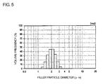
- the present invention still further provides a thermal transfer image receiving sheet having at least a thermal insulation layer and an image receiving layer, characterized in that the sheet is made of a film laminate obtained by: melt-coextruding the thermal insulation layer which comprises a thermoplastic resin and a filler, and the image receiving layer which comprises a thermoplastic resin to form a film; and subsequently subjecting the film to drawing treatment, and further characterized in that an average particle diameter of the filler according to the Coulter Counter method is from 1 ⁇ m to 4 ⁇ m, and the following particle size distribution is generated: an amount of the filler which is 1 ⁇ m or less in size is 15% or less, and an amount of the filler which is 3 ⁇ m or more in size is 15% or less.
- thermoplastic resin used in at least one of the thermal insulation layer and the image receiving layer is preferably a polyester resin.
- the filler in the thermal insulation layer is preferably made of plurality of silicone resin-fine particles or plurality of silicone resin coated fine particles.
- a side of the thermal insulation layer of the film laminate and the substrate sheet may be melt-extruded and laminated onto each other.
- the present invention also provides a thermal transfer image receiving sheet comprising at least an adhesion-improving layer, a thermal insulation layer and an image receiving layer formed in this order, characterized in that the sheet is made of a film laminate obtained by: melt-coextruding the adhesion-improving layer which comprises a thermoplastic resin, the thermal insulation layer which comprises a thermoplastic resin and a filler, and the image receiving layer which comprises a thermoplastic resin to forma film; and subsequently subjecting the film to drawing treatment, and further characterized in that an average particle diameter of the filler according to the Coulter Counter method is from 1 ⁇ m to 4 ⁇ m, and the following particle size distribution is generated: an amount of the filler which is 1 ⁇ m or less in size is 15% or less, and an amount of the filler which is 3 ⁇ m or more in size is 15% or less.
- thermoplastic resin used in at least one of the adhesion-improving layer, the thermal insulation layer, and the image receiving layer is preferably a polyester resin.
- a side of the adhesion-improving layer of the film laminate and the substrate sheet may be melt-extruded and laminated onto each other.
- the above-mentioned image receiving layer preferably comprises an amorphous polyester resin.
- the image receiving layer comprises the amorphous polyester resin, the dyeability of the image receiving layer is improved so that the density of a printed image is improved.
- the draw ratio by area in the drawing treatment is between 3.6 or more to 25 or less.
- the present invention further provides a method for manufacturing a thermal transfer image receiving sheet comprising at least a thermal insulation layer and an image receiving layer, characterized in that: the thermal insulation layer which comprises a thermoplastic resin and a filler, and the image receiving layer which comprises a thermoplastic resin are melt-coextruded to form a film; and the film is subsequently subjected to drawing treatment to form a film laminate; and further characterized in that an average particle diameter of the filler used according to the Coulter Counter method is from 1 ⁇ m to 4 ⁇ m, and the following particle size distribution is generated: an amount of the filler which is 1 ⁇ m or less in size is 15% or less, and an amount of the filler which is 3 ⁇ m or more in size is 15% or less.
- thermoplastic resin used in at least one of the above-mentioned thermal insulation layer and the above-mentioned image receiving layer is preferably a polyester resin.
- the present invention still further provides a method for manufacturing a thermal transfer image receiving sheet, in which the thermal insulation layer and the image receiving layer are formed on a substrate sheet, characterized in that the film laminate mentioned in the above embodiment is formed, and a side of the thermal insulation layer of the laminate and the substrate sheet are subsequently melt-extruded and laminated onto each other.
- the invention also provides a method for manufacturing a thermal transfer image receiving sheet comprising at least an adhesion-improving layer, a thermal insulation layer, and an image receiving layer formed in this order, characterized in that the adhesion-improving layer which comprises a thermoplastic resin, the thermal insulation layer which comprises a thermoplastic resin and a filler, and the image receiving layer which comprises a thermoplastic resin are melt-coextruded to form a film; and subsequently the film is subjected to drawing treatment to form a film laminate; and further characterized in that an average particle diameter of the filler used according to the Coulter Counter method is from 1 ⁇ m to 4 ⁇ m, and the following particle size distribution is generated: an amount of the filler which is 1 ⁇ m or less in size is 15% or less, and an amount of the filler which is 3 ⁇ m or more in size is 15% or less.
- thermoplastic resin used in at least one of the adhesion-improving layer, the thermal insulation layer and the image receiving layer disclosed in the above-mentioned embodiment is a polyester resin.
- the present invention provides a method for manufacturing a thermal transfer image receiving sheet, in which the adhesion-improving layer, the thermal insulation layer and the image receiving layer are formed on a substrate sheet in this order, characterized in that the film laminate disclosed in the above-mentioned embodiment is formed, and a side of the adhesion-improving layer of the laminate and the substrate sheet are subsequently melt-extruded and laminated onto each other.
- the draw ratio by area in the above-mentioned drawing treatment is preferably between 3.6 or more to 25 or less.
- the present invention achieves the effect of providing a thermal transfer image receiving sheet excellent in releasability even after printing is performed plural times. Further, the invention achieves the effects of solving a fall in sensitivity in the case of using, as a substrate sheet, a pieceof pulppapersuchas coatedpaper, anda fall inproductivity, an increase in costs, and other drawbacks in the case of using a laminate-stuck sheet made of void-containing bi-axially drawn sheet and a core member, so as to provide an inexpensive thermal transfer image receiving sheet which has such a high performance that a highly-dense and high-resolution image can be obtained without generating density unevenness or dot omission, and which is good in productivity.
- thermal transfer image receiving sheet of the invention and the method thereof for manufacturing a thermal transfer image receiving sheet will be described hereinafter.
- thermal transfer image receiving sheet of the invention and the method thereof for manufacturing a thermal transfer image receiving sheet can be classified into two embodiments in accordance with the form thereof.
- thermal transfer image receiving sheet of the invention and the method thereof for manufacturing a thermal transfer image receiving sheet will be divided into each of the embodiments, and described.
- thermal transfer image receiving sheet and a method for manufacturing a thermal transfer image receiving sheet according to a first embodiment of the invention are described.
- the thermal transfer image receiving sheet of the present embodiment comprises: a substrate sheet; and an image receiving layer which is formed on the substrate sheet and comprising a binder resin, a high molecular weight silicone, and a low molecular weight-modified silicone, characterized in that a kinematic viscosity of the high molecular weight silicone is 500000 mm 2 /s or more, and a kinematic viscosity of the low molecular weight-modified silicone ranges from 100 mm 2 /s to 100000 mm 2 /s .
- FIG. 1 is a schematic sectional view illustrating an example of the thermal transfer image receiving sheet according to the embodiment.
- a thermal transfer image receiving sheet 10 according to the embodiment is composed of a substrate sheet 1 and an image receiving layer 2 formed on the substrate sheet 1.
- the image receiving layer 2 contains a binder resin, a high molecular weight silicone having a kinematic viscosity of 500000 mm 2 /s or more, and a low molecular weight-modif ied silicone having a kinematic viscosity ranging from 100 mm 2 /s to 100000 mm 2 /s.
- the thermal transfer image receiving sheet according to the embodiment may have a layer other than the substrate sheet and the image receiving layer.
- FIG. 2 is a schematic sectional view illustrating another example of the thermal transfer image receiving sheet according to the embodiment.
- a thermal transfer image receiving sheet 10' according to the embodiment has a thermal insulation layer 3 and an adhesive layer 4 between a substrate sheet 1 and an image receiving layer 2, and further a rear face layer 5 may be formed on the face of the substrate sheet 1 opposite to the face thereof on which the image receiving layer 2 is formed.
- the image receiving layer contains the low molecular weight-modified silicone and the high molecular weight silicone, whereby the release stability can be improved.
- the mechanism that the image receiving layer contains the lowmolecular weight-modified silicone and the high molecular weight silicone, whereby the release stability can be improved as described above is unclear, but the improvement would be based on the following mechanism.
- the silicone When the low molecular weight-modified silicone is present on the face of the image receiving layer, the surface energy of the image receiving layer can be lowered; thus, the image receiving layer has a high releasability. However, the silicone bleeds out to the surface of the image receiving layer since the silicon has a low molecular weight. Thus, the silicone has a drawback that when a dye is printed onto the image receiving layer, the silicone is transferred onto a thermal transfer sheet. Accordingly, when the low molecular weight-modified silicone is used alone, there is caused a problem that the releasability of the image receiving layer is lowered by printing an image only one time.
- the high molecular weight silicone has a large molecular weight; thus, when a dye is printed onto the image receiving layer, the silicone is less transferred onto the thermal transfer sheet. For this reason, the releasability of the image receiving layer is hardly changed by printing an image one time.
- the high molecular weight silicone has a drawback that the silicone is poorer in the function of lowering the surface energy of the image receiving layer than that of the low molecular weight-modified silicone. Accordingly, when the high molecular weight silicone is used alone, there is caused a problem that a desired releasability cannot be obtained.
- the low molecular weight-modified silicone and the high molecular weight silicone are common in that they have Si. Thus, when these are used in a mixture form, the low molecular weight-modified silicone and the high molecular weight silicone interact with each other through Si.
- the image receiving layer has the low molecular weight-modified silicone and the high molecular weight silicone together, thereby making it possible to prevent the high molecular weight silicone and the low molecular weight-modified silicone from being transferred onto a thermal transfer sheet by the interaction. As a result, an excellent release stability would be able to be expressed.
- the low molecular weight-modified silicone is used as a low molecular weight silicone in the embodiment is that: the silicon has weak compatibility with the image receiving layer resin by the modification, so that the silicone is appropriately restrained from bleeding out when the resin is extruded into a film, when the resin is thermally set after drawn, or when the dye is transferred; therefore, the silicone is present with good balance in the image receiving layer surface, so that a good releasability can be given to the image receiving layer.
- the use of the low molecular weight-modified silicone can produce the following expectations: when a protective layer is transferred after the formation of an image, the bleeding-out of the silicone, which hinders the adhesiveness to the protective layer, is restrained; and the adhesiveness of the protective layer is improved due to the improving effect in the compatibility with the protective layer by using the organically-modified silicone.
- the thermal transfer image receiving sheet according to the embodiment has a substrate sheet and an image receiving layer. Each of the constituents of the thermal transfer image receiving sheet according to the embodiment will be described in detail hereinafter.
- the image receiving layer used in the embodiment is a layer containing a binder resin, a high molecular weight silicone, and a low molecular weight-modified silicone.
- the layer has a function of receiving a dye transferred from a thermal transfer sheet when the thermal transfer image receiving sheet according to the embodiment is used to form an image.
- the high molecular weight silicone used in the embodiment is described.
- the high molecular weight silicone used in the embodiment is characterized by having a kinematic viscosity of 500000 mm 2 /s or more.
- the reason why the kinematic viscosity of the high molecular weight silicone is specified as described in the embodiment is that if the kinematic viscosity is less than 500000 mm 2 /s, the mobility of the high molecular weight silicone in the image receiving layer becomes high so that the function of restraining the low molecular weight-modified silicone, which will be described below, from bleeding out becomes insufficient.
- the kinematic viscosity of the high molecular weight silicone is 500000 mm 2 /s or more in the embodiment.
- the high molecular weight silicone which is in a solid form can also be preferably used.
- the kinematic viscosity of the high molecular weight silicone is in particular preferably 10000000 mm 2 /s or more.
- the kinematic viscosity of the high molecular weight silicone in the embodiment means a value measured at a temperature of 25°C by a viscosity measuring method described in JIS Z8803 unless especially described otherwise.
- the kinematic viscosity can be measured with, for example, a single cylinder type rotary viscometer TVB33H(U) manufactured by Toki Sangyo Co., Ltd.
- the high molecular weight silicone used in the embodiment is not particularly limited as long as the silicone has a polysiloxane structure.
- the silicone is preferably a silicone having compatibility with the binder resin, which will be described later.
- the high molecular weight silicone used in the embodiment may be an unmodified silicone (straight silicone) or a modified silicone. In the embodiment, only one species may be used or two or more species may be used in a mixture form as the high molecular weight silicone.
- unmodified silicone examples include dimethylsilicone, methylphenylsilicone, and methylhydrogensilicone.
- the modified silicone is not particularly limited as long as the silicone has a polysiloxane structure having an organic functional group. It is preferred to use a silicone having a structure, in which methyl groups of dimethyl silicone are partially substituted (modified) with an organic functional group.
- Examples of a modified silicone having such a structure include: a side chain type modified silicone, in which organic functional groups are bonded to a part of side chains of a polysiloxane; a both-terminal type modified silicone, in which organic functional groups are bounded to both terminals of a polysiloxane; a single-terminal type modified silicone, in which an organic functional group is bonded to either one terminal of a polysiloxane; a side-chain both-terminal type modified silicone, in which organic functional groups are bonded to a part of side chains of a polysiloxane and both terminals thereof; a side-chain single-terminal type modified silicone, in which organic functional groups are bonded to a part of side chains of a polysiloxane and one out of terminals thereof; and a main chain type modified silicone, in which an organic functional group is bonded to the main chain of a polysiloxane.
- any one of modified silicones having these structures can be preferably used.
- modified silicones having the above-mentioned structures may be used alone or may be used in the form of a mixture of two or more thereof.
- the organic functional group(s) is/are not particularly limited as long as the group (s) can give a desired releasability to the thermal transfer image receiving sheet according to the embodiment.
- Such organic groups are roughly classified into reactive functional groups, which have reactivity, and unreactive functional groups, which have no reactivity.
- any one of the reactive functional groups and the unreactive functional groups can be preferably used.
- Examples of the reactive functional groups used in the embodiment include amino groups, which may be primary amino groups or secondary amino groups, epoxy groups, carboxyl groups, carbinol groups, mercapto groups, and (meth)acrylic groups.
- unreactive functional groups used in the embodiment include polyether groups, methylstyryl groups, alkyl groups, higher aliphatic acid ester groups, and fluorine-containing functional groups (such as fluoroalkyl groups) .
- the modified silicone used in the embodiment may be a silicone to which a single organic functional group species is bonded, or a silicone to which two or more organic functional group species are bonded.
- the silicone to which the two or more species are bonded may be a silicone to which only reactive functional groups are bonded, or a silicone to which a reactive functional group and an unreactive functional group are bonded.
- modified silicone used in the embodiment there can be used an organic condensed polymer, or a silicone modified polymer, in which an addition polymer (such as polyolefin, polyester, acryl, or ethylene vinyl acetate) is grafted or blocked.
- an addition polymer such as polyolefin, polyester, acryl, or ethylene vinyl acetate
- silicone modified polymer gives an advantage that the compatibility with the binder resin, which will be described later, can be improved.
- the high molecular weight silicone used preferably in the embodiment include dimethylsilicone, methylphenylsiclione, acryl-modified silicone, to which a (meth) acrylic group is bonded, polyester modified silicone, and polypropylene modified silicone, to which a polypropylene group is bonded.
- the content of the high molecular weight silicone contained in the image receiving layer in the embodiment is not particularly limited as long as the content is in such a range that a desired release stability can be given to the thermal transfer image receiving sheet according to the embodiment. It is advisable to decide the content appropriately in accordance with factors such as the kind of the high molecular weight silicone, the kind of the low molecular weight-modified silicone, and which will be described later.
- the content of the high molecular weight silicone in the embodiment is preferably from 0.1 to 10 parts by weight, in particular preferably from 0.5 to 3 parts by weight for 100 parts by weight of the binder resin contained in the image receiving layer.
- the ratio of the content of the high molecular weight silicone in the image receiving layer to that of the low molecular weight-modified silicone, which will be described later, therein is not particularly limited as long as the ratio is in such a range that desired releasability and release stability can be given to the thermal transfer image receiving sheet according to the embodiment. It is advisable to decide the ratio appropriately in accordance with the factors such as kinds of the high molecular weight silicone and the low molecular weight-modified silicone, and the kind of the binder.
- the mass ratio of the high molecular weight silicone to the low molecular weight-modified silicone ranges preferably from 1:4 to 4:1, more preferably from 1:3 to 3:1, in particular preferably from 1:1.
- the low molecular weight-modified silicone used in the embodiment is a silicone mainly having a function of lowering the surface energy of the image receiving layer to improve the releasability of the thermal transfer image receiving sheet according to the embodiment, as described above.
- the silicone is characterized by having a kinematic viscosity of 100 mm 2 /s to 100000 mm 2 /s.
- the reason why the kinematic viscosity of the lowmolecular weight-modified silicone is specified as described above in the embodiment is that: if a silicone which is not organically modified is used and the kinematic viscosity thereof is less than 100 mm 2 /s, the low molecular weight-modified silicone may bleed out from the image receiving layer in accordance with the kind of the high molecular weight silicone and others when the dye is transferred; and if the kinematic viscosity is 100000 mm 2 /s or more, a desired releasability may not be given to the thermal transfer image receiving sheet of the embodiment depending on the kind of the binder resin contained in the image receiving layer, and others.
- the kinematic viscosity of the low molecular weight-modified silicone in the embodiment is not particularly limited as long as the viscosity is in the above-mentioned range.
- the kinematic viscosity is preferably from 300 mm 2 /s to 50000 mm 2 /s, in particular preferably from 1000 mm 2 /s to 30000 mm 2 /s.
- the kinematic viscosity of the low molecular weight-modified silicone in the embodiment means a value at 25°C unless especially described otherwise.
- the measuring method of the kinematic viscosity is equal to that of the kinematic viscosity of the high molecular weight silicone. Thus, description thereof is not repeated herein.
- the low molecular weight-modified silicone used in the embodiment is not particularly limited as long as the silicone has a polysiloxane structure having an organic functional group.
- the structure and the organic functional group of this low molecular weight-modified silicone are equivalent to those described in the above-mentioned item of "(1) High molecular weight silicone". Thus, description thereof is not repeated herein.
- the low molecular weight-modified silicone used in the invention only one species thereof may be used, or two or more species may be used in a mixture form.
- the low molecular weight-modified silicone used in the embodiment include modified silicone , in which a polyether group and an amino group are bonded to each other, polyether modified silicone, and epoxy modified silicone, which are not likely to cause a fall in print sensitivity of the image receiving layer or in the surface property thereof.
- polyether modified silicone is in particular preferably used.
- Polyether groups of polyether modified silicone are partially discomposed by heat (180 °C or higher) at the time of the extruding.
- the remaining polyether groups can keep compatibility-balance with the binder resin, which will be described later; therefore, the bleeding-out is appropriately restrained when the image receiving layer resin is extruded into a film, when the resin is thermally set after drawn, or when the dye is transferred, as described above. For this reason, the silicones can be present with good balance in the image receiving layer surface so that a good releasability can be given to the image receiving layer.
- the content of the low molecular weight-modified silicone contained in the image receiving layer in the invention is not particularly limited as long as the content is in such a range that a desired releasability can be given to the thermal transfer image receiving sheet of the embodiment. It is advisable to decide the content appropriately in accordance with the kinds of the high molecular weight silicone and the low molecular weight-modified silicone, and others.
- the content of the low molecular weight-modified silicone is preferably from 0.1 to 10 parts by weight, in particular preferably from 0.5 to 3 parts by weight for 100 parts by weight of the binder resin contained in the image receiving layer.
- the binder resin used in the embodiment is a resin mainly having a function of giving self supporting properties to the image receiving layer in the embodiment.
- the glass transition temperature thereof is preferably from 50 °C to 100 °C, in particular preferably from 70 °C to 85 °C.
- the weight-average molecular weight (Mw) is preferably 11000 or more, in particular preferably 15000 or more. If the weight-average molecular weight of the binder resin is lower than the range, the elasticity or the heat resistance of the image receiving layer lowers so that it may become difficult to keep releasability between a thermal transfer sheet and the thermal transfer image receiving sheet of the embodiment. Moreover, if the weight-average molecular weight is more than the range, the adhesiveness to the substrate sheet, which will be described later, may deteriorate.
- the weight-average molecular weight in the embodiment can be obtained by, for example, the GPC method.
- binder resins such as polypropylene; halogenated polymers such as polyvinyl chloride, vinylchloride/vinyl acetate copolymer, and polyvinylidene chloride; vinyl polymers such as polyvinyl acetate, ethylene/vinyl acetate copolymer, and polyacrylic ester; polyester resins such as polyethylene terephthalate, and polybutylene terephthalate; polystyrene resins; polyamide resins; copolymer resins each made from an olefin such as ethylene or propylene, and a different vinyl monomer; ionomers; cellulose resins such as cellulose diacetate; polycarbonate resins; phenoxy resins; epoxy resins; polyvinyl acetal resins; and polyvinyl alcohol resins.
- polyolefin resins such as polypropylene
- halogenated polymers such as polyvinyl chloride, vinylchloride/vinyl acetate copo
- hydrogenated petroleum resins include hydrogenated petroleum resins, aliphatic hydrocarbon resins, alicyclic hydrocarbon resins, aromatic hydrocarbon resins, rosin resins, terpene resins, and coumarone-indene resins, which are each known as a tackifying resin or a resin modifier.
- one resin species may be used, or two or more resin species may be used in a mixture form.
- a polyester resin is preferably used as the binder resin.
- An amorphous polyester resin is most preferably used since the dyeability thereof is high.
- the amorphous polyester resin is not particularly limited as long as the resin is substantially amorphous.
- An example of the amorphous polyester resin used in the embodiment is a polyester resin containing, as main components, terephthalic acid and ethylene glycol and containing, as one or more copolymerizable components, a different acid component and/or a different glycol component.
- the acid component examples include aliphatic dibasic acids (such as adipic acid, sebacic acid, and azelaic acid), and aromatic dibasic acids (such as isophthalic acid, diphenyldicarboxylic acid, 5-tert-butylisophthalic acid, 2,2,6,6-tetramethylbiphenyl-4,4-dicarboxylic acid, 2,6-naphthalenedicarboxylic acid, 1,1,3-trimethyl-3-phenylindene-4,5-dicarboxylic acid.
- aliphatic dibasic acids such as adipic acid, sebacic acid, and azelaic acid
- aromatic dibasic acids such as isophthalic acid, diphenyldicarboxylic acid, 5-tert-butylisophthalic acid, 2,2,6,6-tetramethylbiphenyl-4,4-dicarboxylic acid, 2,6-naphthalenedicarboxylic acid, 1,1,3-trimethyl-3-pheny
- glycol component examples include aliphatic diols (such as neopentyl glycol, diethylene glycol, propylene glycol, butanediol, and hexanediol), alicyclic diols (such as 1,4-cyclohexanedimethanol), and aromatic diols (such as xylylene glycol, bis (4- ⁇ -hydroxyphenyl) sulfone, and 2,2-(4-hydroxyphenyl)propane derivatives).
- aliphatic diols such as neopentyl glycol, diethylene glycol, propylene glycol, butanediol, and hexanediol
- alicyclic diols such as 1,4-cyclohexanedimethanol
- aromatic diols such as xylylene glycol, bis (4- ⁇ -hydroxyphenyl) sulfone, and 2,2-(4-hydroxyphenyl)propane derivatives
- a resin in which a polymer (resin) having an epoxy group or carbodiimide group is added to the above-mentioned amorphous polyester resin can be used.
- a binder resin has advantages of: making it possible to improve the extrusion workability at high temperatures and the heat resistance of the image receiving layer since the above-mentioned epoxy-group- or carbodiimide-group-containing polymer cross-linking reacts with the polyester resin; and making it possible to improve the releasability of a high image-printing energy area when an image is printed.
- the above-mentioned epoxy-group-having polymer is made of, for example, an ester made from methacrylic acid or acrylic acid and one ormore out of various glycidyl alcohols, and examples thereof include methylglycidyl ester, butylglycidyl ester, polyethylene glycol diglycidyl ester, polypropylene glycol digycidyl ester, and neopentyl glycol diglycidyl ester.
- carbodiimide-group-having polymer for example, a CARBODILITE® (HMV-8CA) manufactured by Nisshinbo Industries, Inc. can be used.
- HMV-8CA CARBODILITE® manufactured by Nisshinbo Industries, Inc.
- the image receiving layer in the embodiment may contain compounds other than the binder resin, the high molecular weight silicone, and the low molecular weight-modified silicone.
- the other compounds used in the image receiving layer will be described hereinafter.
- a wax may be incorporated into the image receiving layer in the embodiment in order to improve the thermal sensitivity, the thermal transportability and the abrasion resistance.
- the improvement can be attained by adding, as such a wax, for example, a synthetic wax such as a wax-form aliphatic acid amide, any one of various lubricants or a paraffin wax, or a natural wax such as candelilla wax or carnauba wax, an oil such as silicone oil or perfluoroalkyl ether.
- a polyethylene resin a phosphate ester, a resin such as a silicone resin, a tetrafluoroethylene resin or a fluoroalkyl ether resin, and an inorganic lubricant such as silicon carbide or silica.
- a curing agent may be added to the image receiving layer in the embodiment.
- the curing agent is used to react with active hydrogen in the image receiving layer to crosslink and cure the image receiving layer.
- the use of the curing agent makes it possible to give heat resistance to the image receiving layer.
- the curing agent used in the embodiment is not particularly limited as long as the curing agent can give a desired heat resistance to the image receiving layer.
- an isocyanate, a chelate compound or the like is used.
- an isocyanate compound of a non-yellowing type is preferably used. Specific examples thereof include xylylenediisocyanate (xDI), hydrogenated XDI, isophorone diisocyanate (IPDI), hexamethylenediisocyanate (HDI), and adduct bodies/buret bodies, oligomers, and prepolymers thereof.
- a catalyst may be added thereto as a reaction aid for the above-mentioned isocyanate compound.
- a known catalyst can also be used as the reaction aid used in the embodiment.
- a typical example of the catalyst is di-n-butyltindilaurate (DBTDL), which is a tin based catalyst.
- DBTDL di-n-butyltindilaurate
- effective is an aliphatic acid dibutyltin salt based catalyst, an aliphatic acid monobutyltin salt based catalyst, an aliphatic acid monooctyltin salt based catalyst, or a dimer thereof.
- the reaction rate becomes larger; thus, in accordance with the used isocyanate compound(s), the kind thereof, a combination therefrom, and the addition amount should be selected.
- a block type isocyanate compound it is also effective to use a block dissociated catalyst together.
- a UV agent and a light stabilizer may be used in the image receiving layer in the embodiment.
- the UV absorbent and the light stabilizer which can be used in the embodiment are not particularly limited as long as they have a function of improving the light resistance of a thermal transfer printed matter formed by use of the thermal transfer image receiving sheet of the embodiment.
- the UV absorbent and the light stabilizer used in the embodiment may be compounds described in Japanese Patent Application Laid-Open Nos. 59-158287 , 63-74686 , 63-145089 , 59-196292 , 62-229594 , 63-122596 , 61-283595 , and 1-204788 , and compounds each known as a substance for improving the image durability of a photograph or any other image forming material.
- a filler may be incorporated into the image receiving layer in the embodiment.
- the filler which can be used in the embodiment is not particularly limited as long as the filler has a function of improving the lubricity of a thermal transfer sheet by the inclusion thereof into the image receiving layer, and making it possible to give desired high-speed printing properties to the thermal transfer image receiving sheet of the embodiment.
- general inorganic fine particles or organic resin particles can be used as such a filler.
- Examples of the inorganic fine particles include silica gel, calcium carbonate, titanium oxide, acid clay, activated clay, and alumina.
- Examples of the organic fine particles include fluorine-contained resin particles, guanamine resin particles, acrylic resin particles, and silicone resin particles, and other resin particles.
- the content of the filler can be decided at will in accordance with the specific gravity of the filler, and others.
- a pigment which can be used in the embodiment is not particularly limited as long as the pigment has a function of improving the quality of an image formed by means of the thermal transfer image receiving sheet of the embodiment by the inclusion thereof into the image receiving layer.
- the pigment which can be used in the embodiment include titanium white, calcium carbonate, zinc oxide, barium sulfate, silica, talc, clay, kaolin, activated clay, andacidclay. The addition amount of such a pigment can be used at will as long as the objects of the embodiment are not damaged.
- a plasticizer which can be used in the embodiment is not particularly limited as long as the plasticizer has a function of improving the diffusibility of the dye in the image receiving layer by the inclusion thereof into the image receiving layer.
- the plasticizer which can be used in the embodiment include phthalic acid esters, trimellitic acid esters, adipic acid esters, other saturated or unsaturated carboxylic acid esters, citric acid esters, epoxidized soybean oil, epoxidized linseed oil, epoxystearic acid epoxy compounds, orthophosphoric esters, phosphorus esters, and glycol esters.
- the content of the plasticizer can be decided at will in accordance with the kind of the plasticizer and others as long as the objects of the embodiment are not damaged.
- the image receiving layer in the embodiment may contain a releasing agent other than the high molecular weight silicone and the low molecular weight-modified silicone.
- a releasing agent other than the high molecular weight silicone and the low molecular weight-modified silicone.
- the releasing agent used in the embodiment there can be used, for example, a phosphate ester compound, a fluorine-contained compound, and a releasing agent known in the present technical field.
- the image receiving layer in the embodiment may be made into a monolayer, or may be optionally made into two or more layers.
- layers equal to each other in composition or the like may be laminated onto each other, or layers different from each other in composition may be laminated onto each other.
- the thickness of the image receiving layer in the embodiment can be decided at will in accordance with the usage of the thermal transfer image receiving sheet according to the embodiment, and others. Usually, the thickness is preferably from 0.5 ⁇ m to 50 ⁇ m, in particular preferably from 1 ⁇ m to 20 ⁇ m. If the thickness of the image receiving layer is smaller than the range, the mechanical strength of the image receiving layer is low so that the image receiving layer may be "cracked” or "torn". If the thickness is larger than the range, it may become difficult that an image receiving layer excellent in flatness is formed.
- the above-mentioned thickness range corresponds to the total thickness.
- the substrate sheet used in the embodiment is a sheet having a function of supporting the image receiving layer formed on the substrate sheet and expressing self supporting properties of the thermal transfer image receiving sheet according to the embodiment.
- the substrate sheet used in the embodiment is not particularly limited as long as the sheet has desired self supporting properties, mechanical strength and others in accordance with the usage of the thermal transfer image receiving sheet of the embodiment, and others.
- a substrate sheet may be, for example, a condenser paper, a glassine paper, a parchment paper, a paper having a high sizing degree, a (polyolefin type or polystyrene type) synthetic paper, a fine quality paper, an art paper, a coated paper, a cast coated paper, a wallpaper, a lining paper, a synthetic resin or emulsion impregnated paper, a synthetic rubber latex impregnated paper, a synthetic resin internally-added paper, a paperboard, a cellulose fiberpaper, or a filmmade of polyester, polyacrylate, polycarbonate, polyurethane, polyimide, polyetherimide, a cellulose derivative, polyethylene, ethylene/vinyl acetate copolymer, polypropylene, polystyren
- the substrate sheet used in the embodiment there can also be used a white opaque film obtained by adding a white pigment or filler to any one of these synthesized resins and then making the resultant into a film, or a foamed sheet , in which any one of these resins is foamed.
- the substrate sheet used in the embodiment maybe a laminate made of any combination from the above-mentioned substrate sheets.
- a pulp paper such as a fine quality paper, art paper, coated paper or cast coated paper.
- the use of such a pulp paper makes it possible to decrease costs or attain some other advantage.
- the thickness of the substrate sheet used in the embodiment is usually from about 10 ⁇ m to 300 ⁇ m.
- the surface of the substrate sheet when the adhesiveness between the substrate sheet and a layer formed thereon is poor, it is preferred to subject the surface of the substrate sheet to various primer treatments or corona discharge treatment.
- the thermal transfer image receiving sheet of the embodiment may have a constituent different from the image receiving layer and the substrate sheet.
- a constituent different from the image receiving layer and the substrate sheet is not particularly limited as long as the constituent can give a desired function to the thermal transfer image receiving sheet of the embodiment. Examples of the different constituent which can be used in the embodiment will be described in turn.
- a thermal insulation layer used in the embodiment is a layer which is usually formed between the substrate sheet and the image receiving layer and has such heat insulating properties that when heat is applied to the image receiving layer, the substrate sheet and so on are prevented from being thermally damaged.
- the thermal insulation layer also has a function of givingcushionproperties to the thermal transfer image receiving sheet of the embodiment to improve the image-printingperformance thereof.
- the thermal insulation layer used in the embodiment usually contains a thermoplastic resin, and at least one of an incompatible resin which is incompatible with the thermoplastic resin or a filler.
- thermoplastic resin used in the thermal insulation layer examples include polyolefin resins such as polypropylene, halogenated polymers such as polyvinyl chloride and polyvinylidenechloride, vinyl resins suchaspolyvinyl acetate, ethylene vinyl acetate copolymer, vinyl chloride vinyl acetate copolymer and polyacrylic ester, acetal resins such as polyvinyl formal, polyvinyl butyral and polyvinyl acetal, various saturated or unsaturatedpolyester resins, polycarbonate resins, cellulose resins such as cellulose acetate, styrene based resins such as polystyrene, acryl/styrene copolymer, acrylonitrile/styrene copolymer, urea resins, melamine resins, and polyamide resins such as benzoguanamine resin.
- a blend of any two or more out of these resins can be used as long as the extrusion workability is kept and
- thermoplastic resin a polyester resin.
- the polyester resin is excellent in drawing suitability and also has an advantage about costs.
- the polyester resin is, for example, a polyester resin obtained by polycondensing an aromatic dicarboxylic acid such as terephthalic acid, isophthalic acid or naphthalene dicarboxylic acid, or an ester thereof, and a glycol such as ethylene glycol, diethylene glycol, 1,4-butanediol or neopentyl glycol.
- Typical examples of this polyester include polyethylene terephthalate resin, polybutylene terephthalate resin, polyethylene/butylene terephthalate, and polyethylene-2,5-naphthalate.
- These polyester resins may each be a homopolymer or a copolymer, in which a third component is also copolymerized.
- the copolymer has an advantage that the drawing suitability is improved and the drawn ratio can be made high.
- the incompatible resin used in the thermal insulation layer is not particularly limited as long as the resin is incompatible with the thermoplastic resin, is uniformly incorporated and dispersed into the thermoplastic resin, and exfoliates in the interface with the thermoplastic resin at the time of drawing the resins for the thermal insulation layer, so as to become sources for generating voids.
- an example of the incompatible resin in the case of using, as the thermoplastic resin, the above-mentioned polyester resin is not particularly limited as long as the incompatible resin is incompatible with the polyester resin, is uniformly incorporated and dispersed into the polyester resin, and exfoliates in the interface with the polyester resin at the time of drawing the resins for the thermal insulation layer, so as to become sources for generating voids.
- examples of such an incompatible resin include polystyrene resins, polyolefin resins, polyacrylic resins, polycarbonate resins, polysulfone resins, and cellulose resins. In the thermal insulation layer, these may be used alone or may be optionally used in the form of a composite of two or more thereof. Alternatively, when these resins are copolymerized, an appropriate affinity with the polyester resin can be given thereto.
- polystyrene resins or polyolefin resins such as polymethylpentene, polypropylene or cyclic olefins.
- the ratio between the thermoplastic resin, which insulates heat, and the incompatible resin in the thermal insulation layer is as follows: the content by percentage of the incompatible resin in the total amount of the resin composition of the thermal insulation layer is preferably from 3 to 40% by mass, inparticular preferably from 5 to 30% by mass. If the content by percentage of the incompatible resin is smaller than the range, a desired void ratio cannot be given to the thermal insulation layer so that the heat resistance, the cushion properties and other properties thereof may become insufficient. If the content is larger than the range, the heat resistance and the mechanical strength may lower.
- the thermal insulation layer used in the embodiment may be made mainly of the above-mentioned thermoplastic resin and a filler.
- the filler used in this case is not particularly limited as long as the filler is incompatible with the thermoplastic resin, is uniformly incorporated and dispersed into the thermoplastic resin, and exfoliates in the interface with the thermoplastic resin at the time of drawing the resins for the thermal insulation layer, so as to become sources for generating voids.
- the filler used in the embodiment for example, the following can be used: inorganic fillers such as silica, kaolin, talc, calcium carbonate, zeolite, alumina, barium sulfate, carbonblack, zincoxide, and titanium oxide; and organic fillers such as a crosslinking polymer and an organic white pigment.
- the size of these fillers is set to have an average particle diameter of about 0.5 ⁇ m to 3 ⁇ m when they are used.
- a silicone filler is particularly preferred from the viewpoint of easiness in generating of the interface exfoliation, sharpness of the particle size distribution, and others.
- the thermal insulation layer used in the embodiment may contain an antistatic agent, an ultraviolet absorbent, a plasticizer, a dispersing agent, a colorant, a compatibility accelerator, and so on as components other than the above-mentioned thermoplastic resin, incompatible resin and filler.
- the dispersing agent has an effect of making the dispersion diameter of the incompatible resin fine or attaining uniform dispersion of the filler, so as to make it possible to make formed voids fine.
- the dispersing agent which exhibits the above-mentioned effect, may be more preferably an olefin polymer or copolymer having a polar group, such as a carboxyl group or epoxy group, or a functional group reactive with the polyester; diethylene glycol; polyalkylene glycol; or a surfactant. These may be used alone or in combination of two or more thereof.
- the examples of the compatibility accelerator may be a block copolymer; a graft copolymer; a polymer having, at its terminal or side chain, a functional group; or a high molecular weight macromer, which has a polymerizable group at a terminal of a polymer.
- the void ratio of the thermal insulation layer used in the embodiment is not particularly limited as long as the ratio makes it possible to realize desiredheat insulating properties, cushion properties and other properties. It is advisable to decide the ratio at will in accordance with the material which constitutes the thermal insulation layer, and others.
- the ratio is preferably from 15% to 65%. If the void ratio is smaller than the range, the ratio of pores which are finely porous micro-voids is small so that the features of the thermal insulation layer in the embodiment, such as satisfactory heat insulating properties and cushion properties, may not be exhibited. If the void ratio of the thermal insulation layer is larger than the range, a coated film remaining on the thermal insulation layer becomes thin or the finely voids or pores crumble so that micro-voids may not be formed.
- the density (p) of the thermal insulation layer is the density of the thermal insulation layer having a foamed structure and is a numerical value about the structure, which contains voids.
- the density ( ⁇ 0 ) of the whole of the resin, the filler, and the other solid components which constitute the thermal insulation layer is the density of the solids alone which contain no voids.
- the density (p) of the foamed-structure-having thermal insulation layer used in the embodiment is preferably from 0.3 g/cm 3 to 1.0 g/cm 3 .
- the thickness of the thermal insulation layer used in the embodiment is not particularly limited as long as the thickness makes it possible to express desired heat insulating properties, cushion properties and other properties in accordance with the materials which constitute the thermal insulation layer, and others. Usually, the thickness is set into the range of about 10 ⁇ m to 100 ⁇ m. If the thickness of the thermal insulation layer is smaller than the range, desired heat insulating properties, cushion properties and other properties may not be expressed. If the thickness is larger than the range, the heat resistance and the mechanical strength may lower.
- an adhesive layer having adhesiveness to the image receiving layer and the substrate sheet may be formed between the two.
- the formation of such an adhesive layer gives an advantage that it becomes easy to laminate the substrate sheet and the image receiving layer.
- the adhesive which constitutes the adhesive layer is not particularly limited as long as the adhesive exhibits adhesiveness to layers adjacent to the adhesive layer. It is preferred to use a resin, in which necking-in (a phenomenon that the width of a film becomes narrower than the die width, or the degree thereof) is less caused or is smaller and the drawing-down properties, index of the high-speedspreadability and high-speed workability, are relatively good.
- an adhesive examples include polyolefin resins such as high density polyethylene, middle density polyethylene, low density polyethylene, polypropylene, ethylene/vinyl acetate copolymer, ethylene/acrylic acid copolymer (EAA), ethylene/methacrylic acid copolymer (EMAA), ethylene/maleic acid copolymer, ethylene/fumaric acid copolymer, ethylene/maleic anhydride copolymer, ethylene/methyl acrylate copolymer, and ethylene/methyl methacrylate copolymer; polyester resins such as polyethylene terephthalate; ionomer resins; nylons; polystyrene; and polyurethane.
- polyolefin resins such as high density polyethylene, middle density polyethylene, low density polyethylene, polypropylene, ethylene/vinyl acetate copolymer, ethylene/acrylic acid copolymer (EAA), ethylene/methacrylic acid copolymer (EMAA), ethylene
- an acrylic resin can also be used.
- the acrylic resin which can be usedas the adhesive maybe an acrylamide made mainly of acrylic acid (and/or methacrylic acid) and a derivative thereof, an acrylic resin obtained by polymerizing acrylonitrile, any other acrylic acid ester, a copolymer resin, in which a different monomer such as styrene is copolymerized, or the like.
- an acrylic resin examples include homopolymers or copolymers each containing a ester(meth)acrylate, such as polymethyl (meth)acrylate, polyethyl (meth)acrylate, polybutyl (meth)acrylate, methyl (meth)acrylate/butyl (meth)acrylate copolymer, methyl (meth)acrylate/2-hydroxyethyl (meth)acrylate copolymer, butyl (meth)acrylate/2-hydroxyethyl (meth)acrylate copolymer, methyl (meth)acrylate/2-hydroxypropyl (meth)acrylate copolymer, methyl (meth)acrylate/butyl (meth)acrylate/2-hydroxyethyl (meth)acrylate copolymer, and styrene/methyl (meth)acrylate copolymer.
- the wording " (meth) acrylate” herein is used as a wording having a meaning of acrylate and methacryl
- the adhesive described above may be made of one resin species or may be a mixture of plural resin species.
- a rear face layer may be formed in the thermal transfer image receiving sheet used in the embodiment.
- the function of such a rear face layer is not particularly limited, and a layer having a desired function can be formed in accordance with the usage of the thermal transfer image receiving sheet of the embodiment, and others.
- a rear face layer having a function of improving the transportability of the thermal transfer image receiving sheet or a function of preventing the sheet from curling.
- the constituting material of the rear face layer having such a function is not particularly limited as long as the material is a material capable of giving a desired transportability or curl preventing performance to the rear face layer.
- a product in which a filler is added as an additive to a resin such as acrylic resin, cellulose resin, polycarbonate resin, polyvinyl acetal resin, polyvinyl alcohol resin, polyamide resin, polystyrene resin, polyester resin, or halogenated polymer.
- the rear face layer is formed by curing the above-mentioned resin with a curing agent.
- a curing agent is not particularly limited as long as the agent makes it possible to cure the resin.
- a generally known resin may be used.
- an isocyanate compound is preferred since the rear face layer resin reacts with the isocyanate compound or the like to form a urethane bond, so that the resin is cured and made into a three-dimensionally form, thereby improving the heat resistance storability and the solvent resistance and further making the adhesiveness to the substrate sheet good.
- the addition amount of the curing agent is not particularly limited as long as the amount is in such a range that a desired hardness can be given to the rear face layer.
- the amount is preferably from 1 to 2 for one reactive group equivalent of the resin. If the amount is less than 1, much time is required until the curing of the resin is finished and further the heat resistance or the solvent resistance may deteriorate. If the amount is more than 2, after the formation of the resin into a film the film changes with time or there may be caused an inconvenience that the lifespan of a coating solution for the rear face layer is short.
- the filler is not particularly limited as longas the filler can give a desired lubricity to the rear face layer.
- a filler there can be used an organic filler such as an acrylic filler, a polyamide filler, a fluorine-contained filler or polyethylene wax, or an inorganic filler such as silicon dioxide or a metal oxide.
- a polyamide filler is preferred out of the above-mentioned organic and inorganic fillers.
- the polyamide filler has a high melting point and thermal stability, and is good in oil resistance, chemical resistance and others so as not to be easily dyed with a dye.
- a filler in a spherical form is used. It is advisable to adjust the average particle diameter in accordance with the addition amount of the filler, which will be described later, and other factors. Usually, the average particle diameter is preferably from 0.01 ⁇ m to 30 ⁇ m, in particular preferably from 0.01 ⁇ m to 10 ⁇ m. If the average particle diameter is smaller than the range, the filler hides into the rear face layer so that the function of a sufficient lubricity is not expressed with ease. If the average particle diameter is larger than the range, the filler projects largely from the rear face layer so that the frictional coefficient may be made high or the filler may fall away. As the polyamide filler, a mixture of two or more polyamide fillers having different average particle diameters can also be used.
- nylon resin As the constituting material of the polyamide filler, a nylon resin is preferably used.
- the nylon resin include nylon 6, nylon 66, and nylon 12.
- nylon 12 is preferably used.
- the nylon 12 filler is so good in water resistance that a change in the characteristics thereof based on water absorption is relatively small.
- the content by percentage of the filler in the rear face layer is preferably from 0.01 to 200% by mass, in particular preferably from 1 to 100% by mass, especially preferably from 0 . 05 to 2% by mass of the above-mentioned resinwhich constitutes the rear face layer. If the content is smaller than the range, the lubricity becomes insufficient so that inconveniences such as a paper jam may be caused when a paper sheet is supplied to a printer. If the content is larger than the range, the thermal transfer image receiving sheet slips excessively so that a color mismatch or some other defect may be generated in a printed image.
- the method of forming the rear face layer is not particularly limited as long as the method is a method capable of making the formed rear face layer very good in flatness.
- An ordinary method can be used.
- Such a method is, for example, a method of coating a coating solution for forming the rear face layer containing the above mentioned resin and filler onto the above-mentioned core member and then drying the solution to form a film.
- the thermal transfer image receiving sheet according to the embodiment may have a constituent other than the above.
- the constituent other than the above is, for example, an antistatic layer.
- the method for manufacturing the thermal transfer image receiving sheet according to the embodiment is not particularly limited as long as the method makes it possible to manufacture the thermal transfer image receiving sheet, which has the above-mentioned structure.
- the sheet can be manufactured by, for example, a method described in the item of "B. Method for manufacturing a thermal transfer image receiving sheet", which will be described later.
- the method for manufacturing a thermal transfer image receiving sheet of the present embodiment comprises: an image receiving layer forming process of melt-extruding an image receiving layer forming resin which comprises a binder resin, a high molecular weight silicone and a low molecular weight-modified silicone, thereby forming an image receiving layer; and a laminatingprocess of laminating the image receiving layer formed in the image receiving layer forming process and asubstratesheet, thereby manufacturing a thermal transfer image receiving sheet, in which the image receiving layer is laminated on the substrate sheet, characterized in that a kinematic viscosity of the high molecular weight silicone is 500000 mm 2 /s or more, and a kinematic viscosity of the low molecular weight-modified silicone ranges from 100 mm 2 /s to 100000 mm 2 /s.
- the image receiving layer forming process is a process of melt-coextruding an image receiving layer forming resin, and a thermal insulation layer forming resin comprising a thermoplastic resin and at least one of an incompatible resin which is incompatible with the thermoplastic resin or a filler, thereby forming an image receiving layer laminate, in which an image receiving layer and a thermal insulation layer are laminated;
- the laminating process is a process of performing the lamination to cause the thermal insulation layer of the image receiving layer laminate and a substrate sheet to be bonded to each other; and the process further comprises a drawing process of drawing the image receiving layer laminate between the image receiving layer forming process and the laminating process.
- FIG. 3 is a schematic view illustrating an example of the thermal transfer image receiving sheet manufacturing method according to the embodiment.
- the thermal transfer image receiving sheet manufacturing method according to the embodiment has: an image receiving layer forming process I of supplying a thermal insulation layer forming resin 21 and an image receiving layer forming resin 22, through different paths, to a die head 23, and then co-extruding the thermal insulation layer forming resin 21 and the image receiving layer forming resin 22, in a state that they are melted, from an outlet 24 in the die head 23, thereby forming a film of an image receiving layer laminate composed of two layers of an image receiving layer 2 anda thermal insulation layer 3; a drawing process II of causing drawing rolls 31 to have peripheral velocities different from each other and using the rolls 31 to draw longitudinally the image receiving layer laminate formed in the image receiving layer forming process I, then using a tenter type transversely-drawing machine 32 to subject the resultant film to transversely
- the image receiving layer forming resin contains the high molecular weight silicone, which has a kinematic viscosity of 500000 mm 2 /s or more, and the low molecular weight-modified silicone, which has a kinematic viscosity of 100 mm 2 /s to 100000 mm 2 /s, thereby making it possible to restrain the low molecular weight-modified silicone from bleeding out at the time of the melt-extrusion. It is therefore possible to manufacture a thermal transfer image receiving sheet high in productivity and excellent in releasability and release stability.
- the thermal transfer image receiving sheet manufacturing method has the image receiving layer forming process and the laminating process. Each of these processes will be described in detail hereinafter.
- the image receiving layer forming process in the embodiment is a process of melt-extruding an image receiving layer forming resin comprising a binder resin, a high molecular weight silicone and a low molecular weight-modified silicone, thereby forming an image receiving layer, characterized in that the kinematic viscosity of the high molecular weight silicone is 500000 mm 2 /s or more and the kinematic viscosity of the low molecular weight-modified silicone is from 100 mm 2 /s to 100000 mm 2 /s.
- the image receiving layer formed in the present process may be a single layer or an image receiving layer laminate, in which the image receiving layer and a different layer are laminated.
- the image receiving layer is formed as the image receiving layer laminate, and it is particularly preferred that the image receiving layer is formed as the image receiving layer laminate, in which the image receiving layer and a thermal insulation layer are laminated.
- the method of forming the image receiving layer in the process is not particularly limited as long as the method makes it possible to make the thickness of the formed image receiving layer even.
- An ordinary method may be used. Examples of such a method may be a T die method or an inflation method.
- the image receiving layer laminate is formed into a film in the process, the following may be used as the method of forming the film: a field block method, a multi-manifold method, a co-extrusion using a T die such as a multi-slot die method, or a co-extrusion method based on an inflation manner using a round die.
- the image receiving layer forming resin used in the process is a resin containing a binder resin, a high molecular weight silicone and a low molecular weight silicone.
- the binder resin, the high molecular weight silicone and the low molecular weight silicone used in the process are equivalent to those described in the above-mentioned item of "A. Thermal transfer image receiving sheet". Thus, description thereof is not repeated herein.
- the content of each of the binder resin, the high molecular weight silicone and the low molecular weight silicone in the image receiving layer forming resin is also equivalent to that in the image receiving layer described in the item of "A. Thermal transfer image receiving sheet". Thus, description thereof is not repeated herein.
- a thermal insulation layer forming resin used to form the thermal insulation layer is a resin containing a thermoplastic resin and at least one of an incompatible resin incompatible with the thermoplastic resin or a filler.
- the thermoplastic resin, the incompatible resin and the filler used in the process are equivalent to those described in the item of "A. Thermal transfer image receiving sheet". Thus, description thereof is not repeated herein.
- thermoplastic resin the incompatible resin and the filler in the thermal insulation layer forming resin
- the content of each of the thermoplastic resin, the incompatible resin and the filler in the thermal insulation layer forming resin is also equivalent to that in the thermal insulation layer described in the item of "A. Thermal transfer image receiving sheet". Thus, description thereof is not repeated herein.
- the laminating process in the embodiment is a process of laminating the image receiving layer formed in the image receiving layer forming process and a substrate sheet.
- the method of laminating the image receiving layer and the substrate sheet in the process is not particularly limited as long as the method makes it possible to laminate the two through a desired adhesive force.
- Examples of the method of using the adhesive to attain the laminating include a method of melt-extruding the adhesive to laminate the substrate sheet and the image receiving layer; and a method of coating a laminating adhesive in a printing manner, such as gravure coating, and then performing wet-laminating or dry-laminating.
- the adhesion faces thereof are not particularly limited as long as the faces are faces on which the two can be bonded to each other.
- the image receiving layer is formed as an image receiving layer laminate in the embodiment, it is particularly preferred that a different layer formed on the image receiving layer is bonded to the substrate sheet. More specifically, in the case of forming an image receiving layer laminate, in which the image receiving layer and a thermal insulation layer are laminated in the image receiving layer forming process, it is preferred in the process that the laminating is performed so as to bond the thermal insulation layer and the substrate sheet to each other.
- the material used as the adhesive is equivalent to the material described in the item of "A. Thermal transfer image receiving sheet". Thus, description thereof is not repeated herein.
- the thermal transfer image receiving sheet manufacturing method may have a process other than the image receiving layer forming process and the laminating process.
- An example of such a process is a drawing process of drawing the image receiving layer formed in the image receiving layer forming process.
- the drawing process makes it possible to cause the thermal insulation layer to have a desired void ratio.
- the method of drawing the image receiving layer in the drawing process is not particularly limited as long as the method is a method making it possible to draw the layer uniformly into a desired draw ratio.
- a method using drawing rolls as illustrated in FIG. 3, or a method using a tenter may be used.
- drawing only into a longitudinal direction or drawing only into a transverse direction can be performed.
- about biaxial drawing into longitudinal and transverse directions it is allowable to adopt an embodiment in which the layer is longitudinally drawn and then the resultant is transversely drawn, an embodiment in which the layer is transversely drawn and then the resultant is longitudinally drawn, or an embodiment in which the layer is longitudinally and transversely drawn at the same time.
- longitudinal drawing or transverse drawing may be dividedly into plural times and carried out. It is also allowable to divide the drawings and carry out some out of the divided drawings alternately.
- the draw ratio by area is preferably adjusted into the range of 3.6 to 25 (inclusive) .
- the surface temperature of the drawing rolls when the image receiving layer is drawn and the temperature of the environment for the drawing treatment are each not lower than the glass transition temperature of the resins which constitute the materials to be drawn and lower than the melting point thereof.
- the temperatures are each, for example, from 60°C to 160°C, preferably from 80°C to 130°C.
- thermal transfer image receiving sheet and a method for manufacturing a thermal transfer image receiving sheet according to a second embodiment of the invention are described.
- the thermal transfer image receiving sheet of the embodiment may be composed of two layers of a thermal insulation layer and an image receiving layer. However, it is desired that two layers of a thermal insulation layer and an image receiving layer, or three layers of an adhesion-improving layer, a thermal insulation layer and an image receiving layer are formed on a substrate sheet.
- the substrate sheet has a function of holding the thermal insulation layer, the image receiving layer and so on, and preferably has such a mechanical strength that a trouble in handling is not caused when the substrate sheet is heated since heat is applied to the substrate sheet when an image is thermally transferred to the thermal transfer image receiving sheet.
- the substrate sheet used in the embodiment may be equivalent to that described in the itemof "A-1 .
- Thermal transfer image receiving sheet according to the first embodiment Thus, detailed description thereof is not repeated herein.
- the adhesive which is melt-extruded at the time of laminating the substrate sheet, and the laminate made of the thermal insulation layer and the image receiving layer or the laminate made of the adhesion-improving layer, the thermal insulation layer and the image receiving layer may be equivalent to that used in the adhesive layer described in the item of "A-1. Thermal transfer image receiving sheet according to the first embodiment". Thus, detailed description thereof is not repeated herein.
- the amount of the adhesive used in the embodiment may be appropriately varied, and is usually from about 1 g/m 2 to 50 g/m 2 (solid contents).
- the thermal insulation layer is made mainly of a material, in which a thermoplastic resin and a filler are mixed with each other.
- the used filler is a filler, in which according to the Coulter Counter method, the average particle diameter is from 1 ⁇ m to 4 ⁇ m, and the following particle size distribution is generated: a particle size distribution in which the amount of the filler which is 1 ⁇ m or less in size is 15% or less, and the amount of the filler which is 3 ⁇ m or more in size is 15% or less.
- the filler is characterized in that according to the Coulter Counter method, the average particle diameter is from 1 ⁇ m to 4 ⁇ m, and the following particle size distribution is generated: a particle size distribution in which the amount of the filler which is 1 ⁇ m or less in size is 15% or less and the amount of the filler which is 3 ⁇ m or more in size is 15% or less.
- the Coulter Counter method is one out of methods for measuring the diameter of particles or the particle size distribution thereof. When a partition wall having one pore is set into an electrolytic solution, electrodes are set on both sides thereof and then a voltage is applied thereto, an electric current flows. The resistance thereof is decided in accordance with the volume of the pore in the partition wall.
- Powdery particles are dispersed in this electrolytic solution to prepare a thin liquid suspension.
- the particles are caused to pass through the pore.
- the amount of the electrolyte is decreased by the volume of the particles, so that the electric resistance increases. Accordingly, the amount of a change in the resistance represents the particle volume, and the generation number of a change in the resistance represents the particles; thus, the particle size distribution can be obtained.
- the particle size distribution is represented by numerical values on the basis of volume.
- An example of a graph of the particle size distribution, based on the Coulter Counter method, of the filler used in the thermal insulation layer of the thermal transfer image receiving sheet in the embodiment is shown in FIG. 5.
- the particle diameter (unit: ⁇ m) of the filler is taken on the transverse axis in the graph.
- the volume frequency (unit: %) of the filler is taken on the vertical axis. It is demonstrated that the particle diameter ranges from 1.2 ⁇ m to 3.5 ⁇ m, and the average particle diameter is about 2 ⁇ m.
- the amount of the filler which is 1.0 ⁇ m or less in size is about 0% and the amount of the filler which is 3.0 ⁇ m or more in size is about 5%.
- the filler in the graph satisfies the requirement that the amount of the filler which is 1 ⁇ m or less in size is 15% or less and the amount of the filler which is 3 ⁇ m or more in size is 15% or less.
- the filler used in the thermal insulation layer in the embodiment is a uniform filler having a narrow (sharp) particle size distribution, is small in the scattering of the particle diameters and having uniform particle diameters. Accordingly, the filler is melt-extruded in the thermoplastic resin, such as polyester resin, and in the drawing process voids can stably be generated in the interface between the filler and the thermoplastic resin. Thus, voids can be uniformly dispersed and formed in the thermal insulation layer. In this way, the heat resistance and the cushion properties of the thermal insulation layer are improved to give an image having a high density and a high resolution in a printed matter.
- the filler is incompatible with the thermoplastic resin which is abase resin of the thermal insulation layer, is uniformly dispersed and incorporated into the thermoplastic resin, and exfoliates in the interface with the base resin when the thermal insulation layer resin is drawn, so as to become sources for generating voids.
- the filler examples include inorganic fillers suchassilica, kaolin, talc, calciumcarbonate, zeolite, alumina, barium sulfate, carbon black, zinc oxide, and titanium oxide; and organic fillers such as polystyrene resins, melamine resins, acrylic resins,organic silicon resins, polyamide resins such as nylon 6, nylon 66, nylon 6, 10 and nylon 12, polyethylene terephthalate resin, polybutylene terephthalate resin, polycarbonate resin, polyimide resin, and polysulfone resin.
- inorganic fillers suchassilica, kaolin, talc, calciumcarbonate, zeolite, alumina, barium sulfate, carbon black, zinc oxide, and titanium oxide
- organic fillers such as polystyrene resins, melamine resins, acrylic resins,organic silicon resins, polyamide resins such as nylon 6, nylon 66, nylon 6, 10 and nylon 12, polyethylene terephthalate resin, polybutylene
- an organic filler a product, in which any one of the above-mentioned resins is crosslinked is preferably used since the strength of the filler itself is high and the external form is not easily deformed.
- an organic silicone resin is preferred as a filler capable of generating voids in the state that the resin is effectively and uniformly dispersed in the thermoplastic resin such as polyester resin.
- a specific example thereof is a filler made of a polyorganosilsesquioxane cured product having a structure crosslinked into a three-dimensional network form.
- organic silicone resin particles SILICONE RESIN POWDERS KMP-590, KMP-701, X-52-854, and other goods manufactured by Shin-Etsu Chemical Co., Ltd. are available, and can be used.
- Silicone resin coated fine particles in which the surfaces of silicone rubber fine particles are coated with a silicone resin, as the filler in the thermal insulation layer, make it possible to generate voids in the state that the particles are effectively and uniformly dispersed in the thermoplastic resin such as polyester resin.
- Such silicone resin coated fine particles are available as a silicone compound powder KMP-605 manufactured by Shin-Etsu Chemical Co. , Ltd., and other goods, and can be used.
- the filler may be surface-treated with a silicone resin, a siloxane resin, a fluorine-contained resin, apolyvinylpyridine resin or the like so as to coat the surface of the filler therewith.
- the thermal insulation layer contains, as essential components, a thermoplastic resin and a filler, and may optionally contain, as other added components, an antistatic agent, an ultraviolet absorbent, a plasticizer, a colorant and so on in appropriate amounts.
- thermoplastic resin which constitutes the thermal insulation layer in the embodiment may be equivalent to that described as the thermoplastic resin used in the thermal insulation layer in the item of "A-1. Thermal transfer image receiving sheet according to the first embodiment".
- a thermoplastic resin arbitrarily blended may be used as long as the extrusion workability is kept and the resin is compatible with the others.
- polyester resin used in the embodiment is equivalent to that described as the polyester resin used in the thermal insulation layer in the item of "A-1. Thermal transfer image receiving sheet according to the first embodiment". Thus, detailed description thereof is not repeated herein.
- compatibility accelerator In order to disperse sufficiently in the base thermoplastic resin and further strengthen the surface thereof to improve the physical properties further, the so-called compatibility accelerator may be used. Such a compatibility accelerator may also be equivalent to that described as the compatibility accelerator used in the thermal insulation layer in the item of "A-1. Thermal transfer image receiving sheet according to the first embodiment". Thus, detailed description thereof is not repeated herein.
- the thermal insulation layer in the embodiment is formed together with the image receiving layer, which is made of a thermoplastic resin, by melt-coextrusion, and then the thermal insulation layer is subjected to drawing treatment, thereby becoming one constituent of the thermal transfer image receiving sheet.
- the thickness of the thermal insulation layer held in the thermal transfer image receiving sheet is from about 10 ⁇ m to 100 ⁇ m after the drawing treatment. If the thickness of the thermal insulation layer is too small, a sufficiently satisfactory heat resistance, cushion properties or the like cannot be exhibited. If the thickness is too large, there are easily caused problems such that the heat resistance and the mechanical strength fall.
- a thermal transfer image receiving sheet having the following layer structure is manufactured: substrate sheet/adhesive layer/adhesion-improving layer/thermal insulation layer/image receiving layer.
- the resin which constitutes the adhesion-improving layer is not limited as long as the resin has adhesiveness to the adhesive layer and the thermal insulation layer and can be worked by melt-extrusion.
- the thermal transfer image receiving sheet of the embodiment is a thermal transfer image receiving sheet composed of at least a thermal insulation layer and an image receiving layer.
- the image receiving layer is made of a thermoplastic resin.
- the thermal insulation layer which is composed of a thermoplastic resin and a filler and the image receiving layer are formed by melt-coextrusion, and then the resultant is subjected to drawing treatment, thereby forming a film laminate.
- the image receiving layer is made mainly of a thermoplastic resin, and the thermoplastic resin described in the thermal insulation layer may be used as it is.
- the image receiving layer has no voids.
- polyester resin, out of thermoplastic resins which may each become a base resin, is preferably used.
- the image receiving layer preferably contains polyester resin, out of the above-mentioned thermoplastic resins, andmorepreferably contains amorphous polyester resin to such an extent that the extrusion workability is not damaged.
- the polyester resin is, for example, polyester resin obtained by polycondensing an aromatic dicarboxylic acid such as terephthalic acid, isophthalic acid or naphthalenedicarboxylic acid, or an ester thereof, and a glycol such as ethylene glycol, diethylene glycol, 1,4-butanediol or neopentyl glycol.
- Typical examples of this polyester resin include polyethylene terephthalate resin, polybutylene terephthalate resin, polyethylene/butylene terephthalate, and polyethylene-2,6-naphthalate. These polyesters may each be a homopolymer or a copolymer, in which a third component is also copolymerized.
- an amorphous polyester resin may be used as the above-mentioned polyester resin.
- the amorphous polyester resin is as follows: first, the polyester resin is any polyester resin as long as the resin is substantially amorphous; and the amorphous polyester resin is equivalent to that described in the above-mentioned item of "A-1. Thermal transfer image receiving sheet according to the first embodiment". Thus, detailed description thereof is not repeated herein.
- the resin which constitutes the image receiving layer may be melted and bonded to a binder resin in a dye layer for keeping a dye at the time of thermal transfer for forming an image.
- various releasing agents internally to a resin for forming the image receiving layer, examples of the agents being a phosphate ester, a surfactant, a fluorine-contained compound, a fluorine-contained resin, a silicone compound, a silicone oil, and a silicon resin.
- a resin cured by the addition of a modified silicone oil is particularly preferred.
- the addition amount of the releasing agent(s) is preferably from 0.5 to 30 parts by mass for 100 parts by mass of the image receiving layer forming resin. If the addition amount does not satisfy this addition amount range, there may be causedproblems such that the dye receiving layer of the thermal transfer image receiving sheet and a sublimation type thermal transfer sheet are melted and bonded to each other, and the print sensitivity falls.
- the releasing agent bleeds out onto the surface of the image receiving layer so that a releasing layer is formed.
- the releasing agent may be separately coated onto the image receiving layer.
- the thickness of the image receiving layer is from about 10 ⁇ m to 100 ⁇ m after the layer is drawn.
- the thermal transfer image receiving sheet of the embodiment is not limited to the above description, and optionally a layer may be added thereto, for example, a rear face layer is formed on the other side of the substrate sheet, or an intermediate layer is formed between any one of the illustrated layers and a layer adjacent thereto.
- thermal transfer image receiving sheet manufacturing method according to the embodiment is described, giving a manufacturing apparatus 100 illustrated in FIG. 4 as an example.
- a thermal insulation layer forming resin 21' in which a polyester resin and a filler are mixed, and an image receiving layer forming resin 22' made of a polyester resin are supplied, through different paths, to a die head 23.
- the thermal insulation layer forming resin and the image receiving layer forming resin are coextruded, in a state that they are melted, from an outlet 24 in the die head 23, thereby forming a film layer composed of two layers of an image receiving layer 2' and a thermal insulation layer 3'.
- a pair of drawing rolls 31 is caused to have peripheral velocities different from each other, and is used to draw the film layer.
- a tenter type transversely-drawing machine 32 is then used to subject the resultant film to transversely drawing treatment, thereby forming a laminate composed of two layers of the image receiving layer 2' and the thermal insulation layer 3'.
- the laminate composed of the two layers can constitute a thermal transfer image receiving sheet.
- an adhesive 42 is optionally melt-extruded from a die head 41, and a supplied substrate sheet 1' and the above-mentioned laminate are passed, with the adhesive 42 interposed therebetween, between a laminate roll 12 and a press roll 13, and pressed by means of the two rolls, so as to attain EC laminating, thereby manufacturing a thermal transfer image receiving sheet 11, in which the adhesive layer 4' , the thermal insulation layer 3' and the image receiving layer 2' are formed in this order on the substrate sheet 1'.
- the heat insulating material and the image receiving layer forming resin materials, in which a polyester resin is used have been described.
- the material and the resin are not limited thereto, and it is allowable to use a thermal insulation layer forming resin, in which a thermoplastic resin other than any polyester resin and a filter are mixed, and an image receiving layer forming resin made of a thermoplastic resin other than any polyester resin.
- thermo transfer image receiving sheet having a structure, in which an adhesive layer, an adhesion-improving layer, a thermal insulation layer and an image receiving layer are formed in this order on a substrate sheet; however, the sheet is not illustrated.
- An adhesion-improving layer made of a thermoplastic resin such as a polyester resin, a thermal insulation layer forming resin, in which a thermoplastic resin, such as a polyester resin, and a filler are mixed with each other, and an image receiving layer forming resinmade of a thermoplastic resin, such as a polyester resin, are supplied through different paths to a die head.
- the adhesion-improving layer forming resin, the thermal insulation layer forming resin, and the image receiving layer forming resin are coextruded, in the state that they are melted, from an outlet in the die head, thereby forming a film layer composed of three layers of an adhesion-improving layer, an image receiving layer, and a thermal insulation layer.
- a pair of drawing rolls is caused to have peripheral velocities different from each other, and is used to draw the film layer longitudinally.
- a tenter type transversely-drawing machine is then used to subj ect the resultant film to transversely drawing treatment, thereby forming a laminate composed of three layers of the adhesion-improving layer, the image receiving layer and the thermal insulation layer.
- This laminate which is composed of the three layers, can constitute a thermal transfer image receiving sheet.
- an adhesive is optionally melt-extruded from a die head, and a supplied substrate sheet and the above-mentioned laminate are passed, with the adhesive interposed therebetween, between a laminate roll and a press roll, and pressed by means of the two rolls so as to attain EC laminating, thereby manufacturing a thermal transfer image receiving sheet, in which the adhesive layer, the adhesion-improving layer, the thermal insulation layer and the image receiving layer are formed in this order on the substrate sheet (see FIG. 4).
- the thermal transfer image receiving sheet manufacturing method is roughly classified into two.
- the first is a method for manufacturing a thermal transfer image receiving sheet composed of a thermal insulation layer and an image receiving layer, and is a process of forming a thermal insulation layer made of a thermoplastic resin such as a polyester resin and a filler, and an image receiving layer made of a thermoplastic resin by melt-coextrusion, and then subjecting the resultant layers to drawing treatment, thereby forming a film laminate.
- the second is a method for manufacturing a thermal transfer image receiving sheet composed of an adhesion-improving layer, a thermal insulation layer and an image receiving layer, and is a process of forming an adhesion-improving layer made of a thermoplastic resin, a thermal insulation layer made of a thermoplastic resin, such as a polyester resin, and a filler, and an image receiving layer made of a thermoplastic resin by melt-coextrusion, and then subjecting the resultant layers to drawing treatment, thereby forming a film laminate.
- any of the two processes it is preferred to supply a substrate sheet, and melt-extrude the substrate sheet, and a laminate made of a thermal insulation layer and an image receiving layer or a laminate made of an adhesion-improving layer, a thermal insulation layer and an image receiving layer so as to laminate them.
- the lamination of the substrate sheet makes it possible to improve the curling preventing properties, and physical strength in handling the sheet.
- the above-mentioned melt-extrusion may be a method using a T die, an inflation method using a round die, or some other extrusion.
- the above-mentionedcoextrusion may be a fieldblock method, a multi-manifold method, a co-extrusion using a T die such as a multi-slot die method, or a co-extrusion method based on an inflation manner.
- the drawing treatment is not limited to the longitudinal and transverse drawing as illustrated in the figure, and drawing only into a longitudinal direction or drawing only into a transverse direction may be performed. Biaxial drawing into longitudinal and transverse directions is not limited to an embodiment, in which transverse drawing treatment is conducted after longitudinal drawing, as illustrated in the figure.
- the drawing may be an embodiment, in which longitudinal drawing is conducted after transverse drawing, or an embodiment, in which longitudinal and transverse drawings are simultaneously conducted.
- longitudinal drawing or transverse drawing may be dividedly carried out. It is also allowable to divide the drawings and carry out some out of the divided drawings alternately.
- the draw ratio by area is preferably adjusted into the range of 3.6 to 25 (inclusive) . If the draw ratio is less than 3.6, the drawing is not sufficiently performed. Thus, voids are not sufficiently generated in the drawn film, so that sufficient heat resistance and cushion properties cannot be exhibited. On the other hand, if the draw ratio is over 25, conditions for the drawing are too strong so that the flatness of the drawn film unfavorably lowers. In order to adjust the draw ratio into the above-mentioned range, it is necessary to adjust appropriately, for example, the surface temperature of the drawing rolls, the temperature of the environment for the drawing treatment, the rotating speed of the drawing rolls, or the running speed of the film.
- the surface temperature of the drawing rolls at the time of the drawing and the temperature of the environment for the drawing treatment are each not lower than the glass transition temperature of the resins which constitute the materials to be drawn and lower than the melting point thereof.
- the temperatures are each, for example, from 60°C to 160°C, preferably from 80°C to 130°C.
- a substrate sheet it is preferred to supply a substrate sheet, and melt-extrude the substrate sheet and a laminate made of a thermal insulation layer and an image receiving layer or a laminate made of an adhesion-improving layer, a thermal insulation layer and an image receiving layer so as to laminate them.
- an adhesive may be melt-extruded to laminate the substrate sheet and the laminate which is made of the thermal insulation layer and the image receiving layer, or the laminate which is made of the adhesion-improving layer, the thermal insulation layer and the image receiving layer; or an adhesive is coated in a printing manner such as gravure coating, and then wet-laminating or dry-laminating may be performed.
- calendaring treatment may be conducted, thereby making it possible to yield a flatter or smoother thermal transfer image receiving sheet.
- the invention is not limited to the above-mentioned embodiments.
- the embodiments are examples and any embodiment which has substantially the same as the technical conception recited in the claims of the invention and produces the same effects and advantageous is included in the technical scope of the invention.
- thermo transfer image receiving sheet and the thermal transfer image receiving sheet manufacturing method according to the first embodiment of the invention working examples and comparative examples thereof are described.
- An image receiving layer forming resin, a thermal insulation layer forming resin and an adhesive layer forming resin each having a composition described below were used to form an image receiving layer 36 ⁇ m in thickness, to which a thermal insulation layer 360 ⁇ m in thickness and an adhesion-improving layer 36 ⁇ m in thickness were laminated in this order by melt-extrusion.
- the thus-formed image receiving layer was drawn at a draw ratio by area of 9 by means of a biaxial drawing machine manufactured by TOYO SEIKI Co., Ltd., and then the layer was set at 240°C for 1 minute, thereby yielding a film of image receiving layer/thermal insulation layer/adhesive layer, 48 ⁇ m in thickness, having fine voids.
- An adhesive (EMAA resin (Nucrel® N09008C, manufactured by DuPont-Mitsui Polychemicals Co. , Ltd.) was used tomelt-extrude and laminate thermally the adhesion-improving layer side of the above-mentioned film of "image receiving layer/thermal insulation layer/adhesive layer", and the core paper side of a substrate sheet on which a core paper 150 ⁇ m in thickness and a PET 25 ⁇ m in thickness were stuck, thereby yielding a thermal transfer image receiving sheet of Example 1.
- EVA resin Nucrel® N09008C, manufactured by DuPont-Mitsui Polychemicals Co. , Ltd.
- a thermal transfer image receiving sheet was formed in the same way as in Example 1 except that the image receiving layer forming resin was changed so as to have a composition described below.
- the yielded sheet was a thermal transfer image receiving sheet of Example 2.
- a thermal transfer image receiving sheet was formed in the same way as in Example 1 except that the image receiving layer forming resin was changed so as to have a composition describedbelow.
- the yielded sheet was a thermal transfer image receiving sheet of Example 3.
- a thermal transfer image receiving sheet was formed in the same way as in Example 1 except that the image receiving layer forming resin was changed so as to have a composition described below.
- the yielded sheet was a thermal transfer image receiving sheet of Example 4.
- a thermal transfer image receiving sheet was formed in the same way as in Example 1 except that the image receiving layer forming resin was changed so as to have a composition described below.
- the yielded sheet was a thermal transfer image receiving sheet of Example 5.
- a thermal transfer image receiving sheet was formed in the same way as in Example 1 except that the image receiving layer forming resin was changed so as to have a composition described below.
- the yielded sheet was a thermal transfer image receiving sheet of Example 6.
- a thermal transfer image receiving sheet was formed in the same way as in Example 1 except that the image receiving layer forming resin was changed so as to have a composition describedbelow.
- the yielded sheet was a thermal transfer image receiving sheet of Example 7.
- a thermal transfer image receiving sheet was formed in the same way as in Example 1 except that the image receiving layer forming resin was changed so as to have a composition described below.
- the yielded sheet was a thermal transfer image receiving sheet of Example 8.
- a thermal transfer image receiving sheet was formed in the same way as in Example 1 except that the image receiving layer forming resin was changed so as to have a composition described below.
- the yielded sheet was a thermal transfer image receiving sheet of Example 9.
- a thermal transfer image receiving sheet was formed in the same way as in Example 1 except that the image receiving layer forming resin was changed so as to have a composition described below.
- the yielded sheet was a thermal transfer image receiving sheet of Example 10.
- a thermal transfer image receiving sheet was formed in the same way as in Example 1 except that the image receiving layer forming resin was changed so as to have a composition described below.
- the yielded sheet was a thermal transfer image receiving sheet of Example 11.
- a thermal transfer image receiving sheet was formed in the same way as in Example 1 except that the image receiving layer forming resin was changed so as to have a composition described below.
- the yielded sheet was a thermal transfer image receiving sheet of Comparative Example 1.
- a thermal transfer image receiving sheet was formed in the same way as in Example 1 except that the image receiving layer forming resin was changed so as to have a composition described below.
- the yielded sheet was a thermal transfer image receiving sheet of Comparative Example 2.
- a thermal transfer image receiving sheet was formed in the same way as in Example 1 except that the image receiving layer forming resin was changed so as to have a composition described below.
- the yielded sheet was a thermal transfer image receiving sheet of Comparative Example 3.
- a thermal transfer image receiving sheet was formed in the same way as in Example 1 except that the image receiving layer forming resin was changed so as to have a composition described below.
- the yielded sheet was a thermal transfer image receiving sheet of Comparative Example 4.
- a thermal transfer image receiving sheet was formed in the same way as in Example 1 except that the image receiving layer forming resin was changed so as to have a composition described below.
- the yielded sheet was a thermal transfer image receiving sheet of Comparative Example 5.
- thermo transfer image receiving sheets of the above-mentioned working examples and comparative examples were evaluated.
- a sublimation transfer printer CP-400 manufactured by Canon Inc. and thermal transfer films were used, and the thermal transfer image receiving sheets of the above-mentioned working examples and comparative examples were used to print black solid images.
- Y, M and C were printed, the releasability was evaluated with the naked eye.
- the evaluating criterion of the evaluation with the naked eye is as follows:
- a transfer film UPC-740 for a sublimation transfer printer UP-D70A manufactured by Sony Corporation was used as a thermal transfer film, and each of the thermal transfer image receiving sheets of the above-mentioned working examples and comparative examples was used, and they were stacked onto each other to oppose the dye layer and the dye receiving face.
- a thermal head was used to make thermal transfer prints from the rear face of the thermal transfer film in order of its Y, M, C and protective layer.
- a gradation image was formed by thermal transfer print under the following conditions:
- An optical reflection densitometer (Macbeth RD-918, manufactured by Macbeth Co.) was used to measure the maximum reflection density of the above-mentioned printed matter through a visual filter.
- Rate ⁇ maximum reflection density of 2.0 or more
- Rate ⁇ maximum reflection density of less than 2.0
- thermo transfer image receiving sheet excellent in releasability and release stability can be obtained.
- An image receiving layer forming resin, a thermal insulation layer forming resin and an adhesion-improving layer each having a composition described below were melt-coextruded into a thickness of 36 ⁇ m, that of 360 ⁇ m and that of 36 ⁇ m, respectively.
- the resultant was drawn at a draw ratio by area of 9 by means of a biaxial drawing machine manufactured by TOYO SEIKI Co., Ltd., thereby yielding a film of "image receiving layer/thermal insulation layer/adhesion-improving layer", 48 ⁇ m in thickness, having fine voids.
- An adhesive having a composition described below was used to melt-extrude and laminate thermally the adhesion-improving layer side of the above-mentioned film of image receiving layer/thermal insulation layer/adhesion-improving layer and the non-rear-face side of a substrate sheet (rear face layer/substrate sheet) having requirements described below, thereby yielding a thermal transfer image receiving sheet of Example 12.
- a rear face layer having a composition described below was thermally melt-extruded into a thickness of 25 ⁇ m onto one surface of a double side coated paper, in which the weight per unit area was 158/m 2 , thereby yielding a substrate sheet.
- a thermal transfer image receiving sheet of Example 13 was yielded in the same way as in Example 12 except that the thermal insulation layer forming resin in Example 12 was changed to have a composition described below.
- a thermal transfer image receiving sheet of Example 14 was yielded in the same way as in Example 12 except that the thermal insulation layer forming resin in Example 12 was changed to have a composition described below.
- a thermal transfer image receiving sheet of Example 15 was yielded in the same way as in Example 12 except that the thermal insulation layer forming resin in Example 12 was changed to have a composition described below.
- a thermal transfer image receiving sheet of Example 16 was yielded in the same way as in Example 12 except that the thermal insulation layer forming resin in Example 12 was changed to have a composition described below.
- the Coulter Counter method demonstrated that the average particle diameter was from 1 ⁇ m to 4 ⁇ m, and the followingparticle size distribution was generated: a particle size distribution, in which the amount of the filler 1 ⁇ m or less in size was 15% or less and that of the filler 3 ⁇ m or more in size was 15% or less.
- a particle size distribution in which the amount of the filler 1 ⁇ m or less in size was 15% or less and that of the filler 3 ⁇ m or more in size was 15% or less.
- a commercially available product was adjusted so as to have the above-mentioned particle size distribution.
- a thermal transfer image receiving sheet of Comparative Example 6 was yielded in the same way as in Example 12 except that the thermal insulation layer forming resin in Example 12 was changed to have a composition described below.
- a thermal transfer image receiving sheet of Comparative Example 2 was yielded in the same way as in Example 12 except that the thermal insulation layer forming resin in Example 12 was changed to have a composition described below.
- a thermal transfer image receiving sheet of Comparative Example 8 was yielded in the same way as in Example 12 except that the draw ratio by area in Example 12 was set to 3.5.
- the print sensitivity was evaluated in the same way as described above.
- the printed matters of the working examples each exhibited such a high density that the maximum reflection density was 2.0 or more, and each gave a high resolution image.
- each of the printed matters of the comparative examples exhibited a maximum reflection density of less than 2.0, which was not satisfactory as a highest print density.
- the thermal insulation layers manufactured in the working examples which had voids, the void ratios were from 35% to 51%, and the densities was from 0.62 g/cm 3 to 0.85 g/cm 3 or less.
- the layers were layers having appropriate voids.
- the void ratios were each less than 25%, and the densities were from 1.02 g/cm 3 to 1.15 g/cm 3 . Thus, it is judged that appropriate voids were not generated.
Landscapes
- Physics & Mathematics (AREA)
- Optics & Photonics (AREA)
- Thermal Transfer Or Thermal Recording In General (AREA)
- Laminated Bodies (AREA)
Priority Applications (1)
| Application Number | Priority Date | Filing Date | Title |
|---|---|---|---|
| EP20090176937 EP2161138B1 (de) | 2005-04-22 | 2006-04-20 | Folie zum Empfang von Bildern durch thermale Übertragung und Herstellungsverfahren dafür |
Applications Claiming Priority (3)
| Application Number | Priority Date | Filing Date | Title |
|---|---|---|---|
| JP2005125166A JP4660265B2 (ja) | 2005-04-22 | 2005-04-22 | 熱転写受像シート及びその製造方法 |
| JP2005282723A JP4664175B2 (ja) | 2005-09-28 | 2005-09-28 | 熱転写受像シート、および、熱転写受像シートの製造方法 |
| PCT/JP2006/308339 WO2006115176A1 (ja) | 2005-04-22 | 2006-04-20 | 熱転写受像シート、および、熱転写受像シートの製造方法 |
Related Child Applications (2)
| Application Number | Title | Priority Date | Filing Date |
|---|---|---|---|
| EP20090176937 Division EP2161138B1 (de) | 2005-04-22 | 2006-04-20 | Folie zum Empfang von Bildern durch thermale Übertragung und Herstellungsverfahren dafür |
| EP09176937.2 Division-Into | 2009-11-24 |
Publications (3)
| Publication Number | Publication Date |
|---|---|
| EP1876029A1 true EP1876029A1 (de) | 2008-01-09 |
| EP1876029A4 EP1876029A4 (de) | 2009-02-04 |
| EP1876029B1 EP1876029B1 (de) | 2010-06-23 |
Family
ID=37214793
Family Applications (2)
| Application Number | Title | Priority Date | Filing Date |
|---|---|---|---|
| EP20090176937 Not-in-force EP2161138B1 (de) | 2005-04-22 | 2006-04-20 | Folie zum Empfang von Bildern durch thermale Übertragung und Herstellungsverfahren dafür |
| EP06745520A Not-in-force EP1876029B1 (de) | 2005-04-22 | 2006-04-20 | Thermotransferbildempfangspapier und verfahren zur herstellung von thermotransferbildempfangspapier |
Family Applications Before (1)
| Application Number | Title | Priority Date | Filing Date |
|---|---|---|---|
| EP20090176937 Not-in-force EP2161138B1 (de) | 2005-04-22 | 2006-04-20 | Folie zum Empfang von Bildern durch thermale Übertragung und Herstellungsverfahren dafür |
Country Status (5)
| Country | Link |
|---|---|
| US (1) | US8039068B2 (de) |
| EP (2) | EP2161138B1 (de) |
| DE (1) | DE602006015045D1 (de) |
| ES (1) | ES2495091T3 (de) |
| WO (1) | WO2006115176A1 (de) |
Cited By (1)
| Publication number | Priority date | Publication date | Assignee | Title |
|---|---|---|---|---|
| EP2161138A2 (de) | 2005-04-22 | 2010-03-10 | Dai Nippon Printing Co., Ltd. | Folie zum Empfang von Bildern durch thermale Übertragung und Herstellungsverfahren dafür |
Families Citing this family (4)
| Publication number | Priority date | Publication date | Assignee | Title |
|---|---|---|---|---|
| JP4932758B2 (ja) | 2008-02-06 | 2012-05-16 | 富士フイルム株式会社 | 発光デバイス及びその製造方法 |
| US9029033B2 (en) * | 2010-10-08 | 2015-05-12 | GM Global Technology Operations LLC | Composite end cell thermal barrier with an electrically conducting layer |
| JP2016117864A (ja) * | 2014-12-24 | 2016-06-30 | 東洋インキScホールディングス株式会社 | 光線反射用樹脂組成物および光線反射シート |
| JP6866200B2 (ja) * | 2017-03-24 | 2021-04-28 | 株式会社巴川製紙所 | 熱転写受像シート |
Citations (5)
| Publication number | Priority date | Publication date | Assignee | Title |
|---|---|---|---|---|
| EP0473783A1 (de) * | 1990-03-14 | 1992-03-11 | KOHJIN CO. Ltd. | Wärmeempfindliche Papierschablone |
| US5726121A (en) * | 1993-12-21 | 1998-03-10 | Ricoh Company, Ltd. | Image receiving sheet for sublimation transfer |
| US5834398A (en) * | 1996-02-02 | 1998-11-10 | Ricoh Company, Ltd. | Sublimation thermal transfer receiving material and image forming method therefor |
| WO2001094121A2 (en) * | 2000-06-07 | 2001-12-13 | Nitto Denko Corporation | Printing apparatus for linerless printing sheet |
| EP1452332A1 (de) * | 2003-02-26 | 2004-09-01 | Eastman Kodak Company | Thermisches Farbstoffübertragungsempfangselement, das Siloxanpolymer enthält |
Family Cites Families (41)
| Publication number | Priority date | Publication date | Assignee | Title |
|---|---|---|---|---|
| JPS59158287A (ja) | 1983-02-28 | 1984-09-07 | Ricoh Co Ltd | 感熱記録材料 |
| JPS59196292A (ja) | 1983-04-21 | 1984-11-07 | Matsushita Electric Ind Co Ltd | 転写記録用像受容体 |
| JPH0664346A (ja) * | 1983-07-25 | 1994-03-08 | Dainippon Printing Co Ltd | 画像形成方法 |
| JPS6034898A (ja) * | 1984-07-17 | 1985-02-22 | Dainippon Printing Co Ltd | 被熱転写シート |
| JPH0714665B2 (ja) | 1985-06-10 | 1995-02-22 | 大日本印刷株式会社 | 被熱転写シ−ト |
| JPS62229594A (ja) | 1986-03-28 | 1987-10-08 | Nec Corp | Fifo回路のデ−タ空領域検出回路 |
| US4705522A (en) | 1986-08-22 | 1987-11-10 | Eastman Kodak Company | Alkolxy derivative stabilizers for dye-receiving element used in thermal dye transfer |
| JPS63122596A (ja) | 1986-11-12 | 1988-05-26 | Mitsubishi Kasei Corp | 感熱転写記録用受像体 |
| JP2571684B2 (ja) * | 1986-11-12 | 1997-01-16 | 大日本印刷株式会社 | 被熱転写シ−ト |
| JPS63145089A (ja) | 1986-12-10 | 1988-06-17 | Dainippon Printing Co Ltd | 被熱転写シ−ト |
| JPS6464888A (en) * | 1987-09-07 | 1989-03-10 | Dainippon Printing Co Ltd | Thermal transfer sheet |
| JPH01204788A (ja) | 1988-02-09 | 1989-08-17 | Fuji Photo Film Co Ltd | 被熱転写シート |
| JP2888527B2 (ja) * | 1988-11-29 | 1999-05-10 | 大日本印刷株式会社 | 被熱転写シート |
| JP2763606B2 (ja) * | 1989-09-01 | 1998-06-11 | 株式会社リコー | 昇華型熱転写用受像媒体 |
| JPH0516539A (ja) | 1991-07-10 | 1993-01-26 | Oji Paper Co Ltd | 染料熱転写受像シート |
| JPH05254263A (ja) * | 1992-03-10 | 1993-10-05 | New Oji Paper Co Ltd | 染料熱転写受像シート |
| JPH05309959A (ja) * | 1992-05-06 | 1993-11-22 | Fuji Photo Film Co Ltd | 熱転写受像材料 |
| JP3286818B2 (ja) * | 1993-01-19 | 2002-05-27 | 大日本印刷株式会社 | 熱転写受像シート |
| JPH06247062A (ja) * | 1993-02-25 | 1994-09-06 | Dainippon Printing Co Ltd | 熱転写受像シート |
| JP3026703B2 (ja) * | 1993-06-23 | 2000-03-27 | 王子油化合成紙株式会社 | 熱転写画像受容シート用支持体 |
| JPH0664345A (ja) * | 1993-07-19 | 1994-03-08 | Dainippon Printing Co Ltd | 被熱転写シート |
| JPH07156563A (ja) * | 1993-12-10 | 1995-06-20 | Ricoh Co Ltd | 昇華型熱転写用受像体 |
| JPH07228064A (ja) * | 1993-12-21 | 1995-08-29 | Ricoh Co Ltd | 昇華転写用受像シートおよび昇華転写記録方法 |
| JPH07242070A (ja) * | 1994-03-04 | 1995-09-19 | Mitsubishi Paper Mills Ltd | 感熱転写記録受像シート用支持体およびその製造方法 |
| JP3336482B2 (ja) * | 1994-07-28 | 2002-10-21 | 大日本印刷株式会社 | ラミネートシート |
| JPH07266723A (ja) * | 1995-02-03 | 1995-10-17 | Dainippon Printing Co Ltd | カード類の製造方法 |
| JPH08323943A (ja) * | 1995-06-01 | 1996-12-10 | Diafoil Co Ltd | ビデオプリンター用積層フィルム |
| JPH091943A (ja) | 1995-06-19 | 1997-01-07 | Fuji Photo Film Co Ltd | 熱転写受像材料 |
| US5910370A (en) * | 1995-11-21 | 1999-06-08 | Ici Americas Inc | Polymeric film |
| JPH10129130A (ja) * | 1996-10-30 | 1998-05-19 | Ricoh Co Ltd | 熱転写受像シート |
| JPH10193812A (ja) * | 1997-01-16 | 1998-07-28 | Ricoh Co Ltd | 熱転写受像シート |
| JPH1148626A (ja) * | 1997-06-03 | 1999-02-23 | Ricoh Co Ltd | 昇華型受像シートおよび昇華型熱転写記録方法 |
| JPH11208127A (ja) * | 1998-01-20 | 1999-08-03 | Ricoh Co Ltd | 熱転写受像体および熱転写記録方法 |
| JP4202508B2 (ja) * | 1999-02-01 | 2008-12-24 | 大日本印刷株式会社 | 熱転写受像シート |
| JP2001030639A (ja) | 1999-07-22 | 2001-02-06 | Dainippon Printing Co Ltd | 熱転写受像シート |
| JP2001138641A (ja) * | 1999-11-12 | 2001-05-22 | Ricoh Co Ltd | 昇華型熱転写受像シート |
| US6638893B2 (en) * | 2001-12-27 | 2003-10-28 | Eastman Kodak Company | Thermal dye transfer receiver element with microvoided support |
| US6890884B2 (en) * | 2003-02-26 | 2005-05-10 | Eastman Kodak Company | Thermal dye-transfer receiver element with microvoided layer |
| JP2004330442A (ja) * | 2003-04-30 | 2004-11-25 | Dainippon Printing Co Ltd | 熱転写受像シート及びその製造方法 |
| JP2005059245A (ja) * | 2003-08-20 | 2005-03-10 | Toray Ind Inc | 感熱転写記録用二軸配向白色フィルムおよびそれからなる感熱転写記録用受容シート。 |
| EP2161138B1 (de) | 2005-04-22 | 2014-08-06 | Dai Nippon Printing Co., Ltd. | Folie zum Empfang von Bildern durch thermale Übertragung und Herstellungsverfahren dafür |
-
2006
- 2006-04-20 EP EP20090176937 patent/EP2161138B1/de not_active Not-in-force
- 2006-04-20 US US11/912,255 patent/US8039068B2/en not_active Expired - Fee Related
- 2006-04-20 WO PCT/JP2006/308339 patent/WO2006115176A1/ja active Application Filing
- 2006-04-20 EP EP06745520A patent/EP1876029B1/de not_active Not-in-force
- 2006-04-20 DE DE602006015045T patent/DE602006015045D1/de active Active
- 2006-04-20 ES ES09176937.2T patent/ES2495091T3/es active Active
Patent Citations (5)
| Publication number | Priority date | Publication date | Assignee | Title |
|---|---|---|---|---|
| EP0473783A1 (de) * | 1990-03-14 | 1992-03-11 | KOHJIN CO. Ltd. | Wärmeempfindliche Papierschablone |
| US5726121A (en) * | 1993-12-21 | 1998-03-10 | Ricoh Company, Ltd. | Image receiving sheet for sublimation transfer |
| US5834398A (en) * | 1996-02-02 | 1998-11-10 | Ricoh Company, Ltd. | Sublimation thermal transfer receiving material and image forming method therefor |
| WO2001094121A2 (en) * | 2000-06-07 | 2001-12-13 | Nitto Denko Corporation | Printing apparatus for linerless printing sheet |
| EP1452332A1 (de) * | 2003-02-26 | 2004-09-01 | Eastman Kodak Company | Thermisches Farbstoffübertragungsempfangselement, das Siloxanpolymer enthält |
Non-Patent Citations (1)
| Title |
|---|
| See also references of WO2006115176A1 * |
Cited By (1)
| Publication number | Priority date | Publication date | Assignee | Title |
|---|---|---|---|---|
| EP2161138A2 (de) | 2005-04-22 | 2010-03-10 | Dai Nippon Printing Co., Ltd. | Folie zum Empfang von Bildern durch thermale Übertragung und Herstellungsverfahren dafür |
Also Published As
| Publication number | Publication date |
|---|---|
| EP2161138A3 (de) | 2010-05-05 |
| ES2495091T3 (es) | 2014-09-16 |
| WO2006115176A1 (ja) | 2006-11-02 |
| US20090061121A1 (en) | 2009-03-05 |
| US8039068B2 (en) | 2011-10-18 |
| EP1876029A4 (de) | 2009-02-04 |
| EP2161138A2 (de) | 2010-03-10 |
| DE602006015045D1 (de) | 2010-08-05 |
| EP1876029B1 (de) | 2010-06-23 |
| EP2161138B1 (de) | 2014-08-06 |
Similar Documents
| Publication | Publication Date | Title |
|---|---|---|
| JP4070329B2 (ja) | 支持体および熱転写画像受容体 | |
| WO2015147288A1 (ja) | 熱転写受像シート用支持体および熱転写受像シートならびにそれらの製造方法 | |
| US8039068B2 (en) | Thermal transfer image receiving sheet, and method for manufacturing same | |
| US4935402A (en) | Dye-receiving sheets for thermal dye transfer printing | |
| JP4368322B2 (ja) | 熱転写受像シート | |
| JP2015174328A (ja) | 熱転写受像シート、熱転写受像シートと保護層転写シートとの組合せ、及び印画物 | |
| JP2006264090A (ja) | 熱転写受像シート | |
| EP2942202B1 (de) | Wärmetransferbildempfangsfolie und bilderzeugungsverfahren | |
| EP1837192B1 (de) | Folie zum empfang von bildern durch thermale übertragung und herstellungsverfahren dafür | |
| JP4506200B2 (ja) | 感熱転写記録用白色積層ポリエステルフィルム | |
| JP4664175B2 (ja) | 熱転写受像シート、および、熱転写受像シートの製造方法 | |
| ES2347977T3 (es) | Lamina de recepcion de imagen de transferencia termica y proceso para producir la lamina de recepcion de imagen de transferencia termica. | |
| JP2009083297A (ja) | 熱転写受像シートの製造方法 | |
| JP2007326324A (ja) | 熱転写受容シート | |
| JPH11334225A (ja) | 熱転写受容シート | |
| JP2019064033A (ja) | 熱転写受像シートと熱転写シートとの組み合わせ | |
| CN114728530B (zh) | 热转印图像接受片、印相物的制造方法和印相物 | |
| JP4000700B2 (ja) | 受容シート | |
| JPH07276827A (ja) | 熱転写受像シート | |
| JP2007296745A (ja) | 熱転写受容シートおよびその製造方法 | |
| JPH0966682A (ja) | 熱転写受像体 | |
| JPH0966681A (ja) | 熱転写受像体 | |
| JP5757400B2 (ja) | 昇華転写用熱転写受像シート | |
| JP2022092348A (ja) | 熱転写受像シート | |
| JP2000335119A (ja) | 熱転写記録用受容シートの製造方法及び受容シート |
Legal Events
| Date | Code | Title | Description |
|---|---|---|---|
| PUAI | Public reference made under article 153(3) epc to a published international application that has entered the european phase |
Free format text: ORIGINAL CODE: 0009012 |
|
| 17P | Request for examination filed |
Effective date: 20071116 |
|
| AK | Designated contracting states |
Kind code of ref document: A1 Designated state(s): DE ES FR GB |
|
| DAX | Request for extension of the european patent (deleted) | ||
| RBV | Designated contracting states (corrected) |
Designated state(s): DE ES FR GB |
|
| A4 | Supplementary search report drawn up and despatched |
Effective date: 20090108 |
|
| 17Q | First examination report despatched |
Effective date: 20090421 |
|
| GRAP | Despatch of communication of intention to grant a patent |
Free format text: ORIGINAL CODE: EPIDOSNIGR1 |
|
| GRAS | Grant fee paid |
Free format text: ORIGINAL CODE: EPIDOSNIGR3 |
|
| GRAA | (expected) grant |
Free format text: ORIGINAL CODE: 0009210 |
|
| AK | Designated contracting states |
Kind code of ref document: B1 Designated state(s): DE ES FR GB |
|
| REF | Corresponds to: |
Ref document number: 602006015045 Country of ref document: DE Date of ref document: 20100805 Kind code of ref document: P |
|
| PLBE | No opposition filed within time limit |
Free format text: ORIGINAL CODE: 0009261 |
|
| STAA | Information on the status of an ep patent application or granted ep patent |
Free format text: STATUS: NO OPPOSITION FILED WITHIN TIME LIMIT |
|
| 26N | No opposition filed |
Effective date: 20110324 |
|
| REG | Reference to a national code |
Ref country code: DE Ref legal event code: R097 Ref document number: 602006015045 Country of ref document: DE Effective date: 20110323 |
|
| REG | Reference to a national code |
Ref country code: FR Ref legal event code: PLFP Year of fee payment: 11 |
|
| REG | Reference to a national code |
Ref country code: FR Ref legal event code: PLFP Year of fee payment: 12 |
|
| REG | Reference to a national code |
Ref country code: FR Ref legal event code: PLFP Year of fee payment: 13 |
|
| PGFP | Annual fee paid to national office [announced via postgrant information from national office to epo] |
Ref country code: FR Payment date: 20210423 Year of fee payment: 16 |
|
| PGFP | Annual fee paid to national office [announced via postgrant information from national office to epo] |
Ref country code: ES Payment date: 20210621 Year of fee payment: 16 Ref country code: GB Payment date: 20210421 Year of fee payment: 16 |
|
| PGFP | Annual fee paid to national office [announced via postgrant information from national office to epo] |
Ref country code: DE Payment date: 20220420 Year of fee payment: 17 |
|
| GBPC | Gb: european patent ceased through non-payment of renewal fee |
Effective date: 20220420 |
|
| PG25 | Lapsed in a contracting state [announced via postgrant information from national office to epo] |
Ref country code: GB Free format text: LAPSE BECAUSE OF NON-PAYMENT OF DUE FEES Effective date: 20220420 Ref country code: FR Free format text: LAPSE BECAUSE OF NON-PAYMENT OF DUE FEES Effective date: 20220430 |
|
| REG | Reference to a national code |
Ref country code: ES Ref legal event code: FD2A Effective date: 20230529 |
|
| PG25 | Lapsed in a contracting state [announced via postgrant information from national office to epo] |
Ref country code: ES Free format text: LAPSE BECAUSE OF NON-PAYMENT OF DUE FEES Effective date: 20220421 |
|
| REG | Reference to a national code |
Ref country code: DE Ref legal event code: R119 Ref document number: 602006015045 Country of ref document: DE |
|
| PG25 | Lapsed in a contracting state [announced via postgrant information from national office to epo] |
Ref country code: DE Free format text: LAPSE BECAUSE OF NON-PAYMENT OF DUE FEES Effective date: 20231103 |