EP1813523B1 - Motorrad - Google Patents
Motorrad Download PDFInfo
- Publication number
- EP1813523B1 EP1813523B1 EP07007044A EP07007044A EP1813523B1 EP 1813523 B1 EP1813523 B1 EP 1813523B1 EP 07007044 A EP07007044 A EP 07007044A EP 07007044 A EP07007044 A EP 07007044A EP 1813523 B1 EP1813523 B1 EP 1813523B1
- Authority
- EP
- European Patent Office
- Prior art keywords
- motorcycle
- frame
- swing arm
- disposed
- tubes
- Prior art date
- Legal status (The legal status is an assumption and is not a legal conclusion. Google has not performed a legal analysis and makes no representation as to the accuracy of the status listed.)
- Expired - Lifetime
Links
Images


Classifications
-
- B—PERFORMING OPERATIONS; TRANSPORTING
- B62—LAND VEHICLES FOR TRAVELLING OTHERWISE THAN ON RAILS
- B62K—CYCLES; CYCLE FRAMES; CYCLE STEERING DEVICES; RIDER-OPERATED TERMINAL CONTROLS SPECIALLY ADAPTED FOR CYCLES; CYCLE AXLE SUSPENSIONS; CYCLE SIDE-CARS, FORECARS, OR THE LIKE
- B62K11/00—Motorcycles, engine-assisted cycles or motor scooters with one or two wheels
- B62K11/02—Frames
- B62K11/04—Frames characterised by the engine being between front and rear wheels
-
- B—PERFORMING OPERATIONS; TRANSPORTING
- B62—LAND VEHICLES FOR TRAVELLING OTHERWISE THAN ON RAILS
- B62K—CYCLES; CYCLE FRAMES; CYCLE STEERING DEVICES; RIDER-OPERATED TERMINAL CONTROLS SPECIALLY ADAPTED FOR CYCLES; CYCLE AXLE SUSPENSIONS; CYCLE SIDE-CARS, FORECARS, OR THE LIKE
- B62K25/00—Axle suspensions
- B62K25/04—Axle suspensions for mounting axles resiliently on cycle frame or fork
- B62K25/28—Axle suspensions for mounting axles resiliently on cycle frame or fork with pivoted chain-stay
- B62K25/283—Axle suspensions for mounting axles resiliently on cycle frame or fork with pivoted chain-stay for cycles without a pedal crank, e.g. motorcycles
-
- B—PERFORMING OPERATIONS; TRANSPORTING
- B62—LAND VEHICLES FOR TRAVELLING OTHERWISE THAN ON RAILS
- B62M—RIDER PROPULSION OF WHEELED VEHICLES OR SLEDGES; POWERED PROPULSION OF SLEDGES OR SINGLE-TRACK CYCLES; TRANSMISSIONS SPECIALLY ADAPTED FOR SUCH VEHICLES
- B62M11/00—Transmissions characterised by the use of interengaging toothed wheels or frictionally-engaging wheels
-
- B—PERFORMING OPERATIONS; TRANSPORTING
- B62—LAND VEHICLES FOR TRAVELLING OTHERWISE THAN ON RAILS
- B62M—RIDER PROPULSION OF WHEELED VEHICLES OR SLEDGES; POWERED PROPULSION OF SLEDGES OR SINGLE-TRACK CYCLES; TRANSMISSIONS SPECIALLY ADAPTED FOR SUCH VEHICLES
- B62M7/00—Motorcycles characterised by position of motor or engine
- B62M7/02—Motorcycles characterised by position of motor or engine with engine between front and rear wheels
Definitions
- the present invention relates to a motorcycle according to the preamble of claim 1, as it is also from the US-A-4,265,330 will be shown.
- the pinion that drives the chain or drive belt is usually offset at least about 65 mm relative to the axis to which the rear swing arm is hinged.
- the clutch is usually arranged on the transmission input shaft in conventional motorcycles. Seen in a side view of the motorcycle thus "covers" the clutch, the transmission output shaft. Under the transmission output shaft is hereinafter understood the shaft on which the pinion is arranged, which drives the chain or the belt, which in turn drives the rear wheel.
- the transmission output shaft is located forward of the swingarm axis.
- Such conventional motorcycle concepts have a number of disadvantages. Due to the offset of sprocket and swingarm axis a certain chain slack is required. Especially in off-road motorcycles that have a travel of 150 mm and more is a considerable chain slack required. For example, a motorcycle with a travel of 300 mm requires a chain slack of about 70 mm.
- a large chain slack leads to relatively high friction losses and requires a special chain guide. With a large chain slack also results in a high chain wear. Another consequence of the large chain slack can be strong running noise due to "chain whipping". An “encapsulation" of the chain is structurally complex, especially with large chain slack.
- the clutch is usually arranged on the transmission input shaft. On the transmission input shaft already quite high torques occur. In order to transfer these high torques permanently, the clutch must be relatively large or run in an oil bath. Oil bath clutches have the disadvantage that they can lead to a relatively rapid contamination of the oil.
- the frame In conventional motorcycles and the frame is usually designed relatively expensive.
- the frame connection between the steering head and lying behind the transmission output shaft swing axle must be passed to the relatively large-sized clutch basket.
- the frame In conventional motorcycles, in which the rocker axis is arranged behind the drive pinion, the frame usually has frame tubes, which extend below the motor on the coupling housing to the Schwingenanlenkddlingen.
- Such frame structures imply an unfavorable flow of force and are also relatively heavy and expensive to manufacture.
- the engine mounting is relatively difficult, since the engine and the transmission are very closely "embedded" in the frame.
- the drive pinion which is intended to drive the chain or the drive belt, would be arranged coaxially with the rocker axis.
- Conceptual approaches are for example in the US Pat. No. 6,755,272 B2 . GB 558 387 . FR 2370 625 . WO 02/094649 A1 or the EP 592 655 B1 described.
- the drive pinion sits but not on the transmission output shaft, but on a separate shaft which is driven by a chain or belt drive from the transmission output shaft. This is structurally relatively complicated and therefore has not prevailed.
- the technical background can also be the FR 1038 140 be counted.
- the object of the invention is to provide a completely new and structurally easy-to-implement motorcycle concept, which makes it possible to avoid the problems of chain slack described above and further allows a simple and optimized in terms of power flow frame construction.
- the transmission has a transmission housing and a transmission output shaft protruding from the transmission housing.
- a "transmission output pinion” is arranged, which via a traction means, such as. B. is coupled via a chain or a toothed belt, arranged with a rear wheel of the motorcycle sprocket.
- the essence of the invention is that the gear output shaft arranged on the transmission output pinion is arranged coaxially to the rocker axis.
- a coaxial arrangement of the Geretesgangsritzels, ie the pinion, which drives the chain or the belt, and the swing arm has the advantage that practically no slack of the "traction means", ie the drive chain or the drive belt must be kept for the compression of the rear swing arm As is the case with conventional motorcycles with chain or belt drive. The Problems associated with chain slack are thus avoided.
- the pivot axis ie the pivot axis about which the rear swing arm pivots, extends through the transmission motor housing.
- gearbox ie the pivot axis about which the rear swing arm pivots
- the swing axle extending through the transmission housing projects out of the transmission housing on opposite sides of the transmission housing. Ends of the swingarm axis can then pivot in the Be mounted frame of the motorcycle.
- the swingarm axis can be stored in the frame by rolling bearings or plain bearings.
- tapered roller bearings can be used for the storage of the rocker axis in the frame.
- the tapered roller bearings can be arranged, for example, in an O arrangement.
- rocker does not necessarily have to be stored in the frame.
- the rocker may also be stored by means of bearings, e.g. Needle bearings to be mounted on or on the transmission output shaft, provided that the transmission output shaft and the engine / transmission housing are designed sufficiently stable to support the initiated by the rocker forces.
- the rear swingarm can be firmly connected to the swingarm axle.
- An easy way is to clamp the rear swing arm by means of a clamp connection on the swing arm axis.
- the transmission output shaft, on which the transmission output pinion is arranged, is preferably mounted in the gearbox housing by rolling bearings.
- the transmission output shaft is designed as a hollow shaft. This has the advantage that the swing axle can be easily inserted through the transmission output shaft, which allows a very simple assembly and disassembly of the rear swing arm.
- the motorcycle on an engine which is installed so that the crankshaft of the engine in a transverse direction, that extends parallel to the swing arm axis.
- the clutch is arranged coaxially with the crankshaft and is preferably arranged on the crankshaft itself. Since higher speeds and smaller torques occur at the crankshaft than at the transmission input shaft, the clutch can be made smaller, ie with a smaller diameter, than in conventional motorcycles.
- the clutch covers, seen in a side view of the motorcycle, the transmission output shaft.
- an arrangement of the clutch on the crankshaft has the advantage that the clutch can be made more compact and that, seen in a side view of the motorcycle, the transmission output shaft is not covered and thus allows a "Durchsteck" the swing arm axis. Since lower torques occur at the crankshaft than at the transmission input shaft, a wide variety of clutch types can be used, e.g. B. Single-disc clutches, multi-disc clutches, dry clutches, wet clutches, etc.
- a “drive element” of the clutch is preferably non-rotatably connected to the crankshaft.
- An “output member” of the clutch is rotatably disposed with respect to the crankshaft and connected to a rotatably mounted on the crankshaft primary pinion.
- the output element may be a clutch basket, which may be integrally connected to the primary pinion.
- the primary pinion can be mounted on the crankshaft by means of a roller bearing or a sliding bearing.
- the primary pinion is mounted by means of a needle bearing on the crankshaft.
- the torque is transmitted from the seated on the crankshaft primary pinion via an intermediate shaft arranged on an intermediate gear to the transmission input shaft.
- the intermediate gear or another gear seated on the intermediate shaft thus meshes with a gear of the transmission input shaft which is offset in the direction of the rear swing arm with respect to the intermediate shaft.
- On the transmission input shaft and on the transmission output shaft a plurality of permanently engageable switchable gear stages are arranged side by side, via which the individual gears of the transmission can be switched.
- the frame has at least two left and two right frame tubes.
- the left frame tubes are substantially mirror-like to the right frame tubes.
- the frame tubes of each frame side intersect each other.
- cutting means that they come together and are connected to each other.
- the frame is designed so that the swingarm axis extends through the "intersection" of the left frame tubes and through the cut collar of the right frame tubes.
- the engine and the transmission of the motorcycle may be arranged in the area between the left and right frame tubes.
- the left and right frame tubes can be conceptually differentiated into left and right lower frame tubes, and left and right upper frame tubes, respectively. Seen in a side view of the motorcycle, can be provided, the two lower frame tubes are substantially straight and extend from the swing axle forward up in an area below a handlebar of the motorcycle and There, for example, connected to a steering head bearing tube. In a plan view of the motorcycle, the two lower frame tubes are not necessarily straight, but may of course be bent.
- the two upper frame tubes are arranged above the lower frame tubes and extend from an area below the handlebar or from a steering head tube to the swingarm axis back down.
- Such a designed frame has many advantages.
- the engine, the gearbox and a radiator of the motorcycle can be used as a preassembled module from below into the area between the left and the right frame tubes, which considerably simplifies assembly and disassembly.
- This in turn has the advantage that in a region below the lower frame tubes and in front of the engine, a continuous cooler can be arranged.
- An air filter of the engine can be very space-saving and protected from splash water in the region near the handlebar between the upper and lower frame tubes above the engine.
- An on-board battery of the motorcycle may be disposed in a swing-axis-near region between the upper and lower frame tubes above the transmission. This area also contains the center of gravity of the motorcycle. An arrangement of the relatively heavy on-board battery in the area of the center of gravity of the motorcycle improves the handling of the motorcycle quite considerably.
- the frame described above also has significant advantages in terms of the arrangement of the shock absorber.
- the shock absorber is arranged between the frame and the Schuachsschwinge and has the task to feather and dampen movements occurring during the journey of the shock absorber.
- a lower end of the strut is hinged to the swingarm.
- An upper end of the strut is hinged to the frame.
- the strut extends from the back below obliquely forward above.
- the upper frame tubes thus act as "pressure rods" and are subjected to compression of the rear swing arm primarily to pressure and little to bending. In contrast to conventional motorcycles so the frame thus allows a much flatter installation of the strut support, which allows for the compression of the shock absorber high progression.
- the fuel tank can be arranged in the above-described motorcycle concept in a lower, closer to the point position than is the case with most conventional motorcycles.
- the fuel tank is arranged in an area above the strut and below the seat of the motorcycle.
- the tank lid of the fuel tank may be located at the top of the fuel tank below the seat. For refueling so only the seat needs to be removed.
- an arrangement in the region above the suspension strut has the advantage that thereby the pivot point of the vehicle can be lowered, which further improves the handling.
- an access opening or a "hole” may be provided, via or over which the filler neck of the fuel tank is accessible. A refueling is then possible without removing the seat.
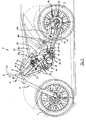
- FIG. 1 shows a motorcycle 1 with a front wheel 2 and a rear wheel 3.
- the front wheel 2 is connected via a telescopic fork 4 with a frame 5 of the motorcycle 1.
- FIG. 1 shown side view of the frame 5 an upper left frame tube 6 and a lower left frame tube 7 can be seen.
- the upper left frame tube 6 can be divided into a front portion 6a and a rear portion 6b. In the transition region between the frame tube sections 6a, 6b, the upper left frame tube 6 is bent.
- the front portion 6a is in the in FIG. 1 shown side view substantially straight.
- the lower left frame tube 7 is in the in FIG. 1 shown side view also substantially straight.
- the two frame tubes 6, 7 extend from an area below a link 8 of a steering head bearing 9 obliquely backwards down.
- the section 6b of the upper left frame tube 6 "cuts" the lower left frame tube 7.
- the frame 5 is constructed substantially symmetrically with respect to a central longitudinal axis of the motorcycle.
- the frame has an upper right frame tube 6 'corresponding to the upper left frame tube 6 and a lower right frame tube 7' corresponding to the lower left frame tube 7.
- the swing axle 10 is best off FIG. 5 seen.
- the rear swing arm 11 (see. FIG. 5 ) attached.
- the rear swing arm 11 is thus arranged pivotably about the swing arm axis 10 with respect to the frame 5.
- a gear output pinion 12 is arranged coaxially to the swing axle 10, which drives a chain 13 of the motorcycle.
- the transmission output pinion 12 is coupled via the chain 13 with a sprocket 14, which drives the rear wheel 3.
- FIG. 1 the top 11a of the rear swinging rocker is hollow.
- a Switzerlandtrum 15 of the chain 13 extends through the upper train 11a of the rear swingarm 11.
- the upper strand 11a thus also serves as a chain guard.
- a lower strand 16 of the chain 13 passes through a hose jacket 17 and is therefore also protected.
- a strut 18 is arranged between the frame 5 and the rear swingarm 11, a strut 18 is arranged. How out FIG. 1 it can be seen, the strut 18 is relatively flat compared to conventional motorcycles. A rear lower end 18a of the strut 18 is pivotally connected to the rear swing arm 11. A front upper end 18b of the strut 18 is pivotally connected to a cross tube of the frame 5, not shown here. How out FIG. 1 it can be seen, the strut 18 is in the side view of the motorcycle shown here substantially in a straight extension to the upper frame tube 6. This results in a very favorable force in the frame 5.
- the upper frame tubes 6, 6 '(see. FIG. 8 ) are thus claimed primarily on pressure.
- shock absorber 18 Due to the relatively "flat" arrangement of the shock absorber 18 results in the deflection of the rear wheel 3 and a relatively high spring progression, which also has a favorable effect on the handling of the motorcycle 1.
- the spring progression is much higher than in conventional motorcycles, where the strut is steeper installed.
- the frame 5 of the motorcycle 1 is downwardly substantially open.
- This has the advantage that the motor 19, the gear 20 and a radiator 21 can be used as a "preassembled power unit" in the assembly of the motorcycle 1 in a simple manner from below into the frame 5, which increases the assembly costs compared to conventional motorcycles, which extend below the engine or the transmission frame tubes, much easier.
- airbox In the area below the handlebar 8, behind the steering head bearing 9 and between the upper frame tubes 6, 6 'and the lower frame tubes 7, 7', a so-called “airbox” is arranged, which includes an air filter, via which the engine 19 is supplied with intake air , Since the airbox is relatively light and thus affects the handling of the motorcycle only slightly, it is located relatively high up on the motorcycle 1, such as where it is in conventional motorcycles tank.
- the fuel tank can be located in a convenient, closer to home position than is the case with most conventional motorcycles.
- the fuel tank 24 is located in a position above the strut 18 and below a seat 25 of the motorcycle 1.
- the fuel tank 24 is thus relatively close to the center of gravity of the motorcycle, which is located approximately in the region of the shock absorber 18.
- the on-board battery 26 is in an area obliquely above or above the swingarm axis 10 between the upper frame tubes 6, 6 'and the lower frame tubes 7, 7' and thus also in the vicinity of the center of gravity of the Arranged, which further improves the handling.
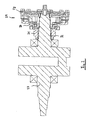
- the engine 19 of the motorcycle 1 is installed so that the crankshaft 27 (see. FIG. 2 ) in the transverse direction of the motorcycle, that is perpendicular to the plane of the FIG. 1 and extends parallel to the swing axle 10.
- the term "transverse direction” may also be interpreted as meaning that the crankshaft is transverse to the main direction of travel and thus transverse to the longitudinal direction of the motorcycle.
- the crankshaft 27 is best off FIG. 2 seen.
- FIG. 2 is the crankshaft of a single-cylinder engine shown.
- the invention is also suitable for transversely mounted multi-cylinder engines.
- the piston (not shown) of the engine transmits a piston force and thereby causes rotation of the crankshaft 27. From the right end of the in FIG. 2 shown crankshaft 27, the torque is transmitted to a drive element 28 of a multi-plate clutch 29.
- the clutch 29 is arranged on the crankshaft 27.
- the torque from the drive member 28 is transmitted to a acting as an "output member” clutch basket 30, which is integrally connected to a primary pinion 31 here.
- the clutch basket does not necessarily have to be integrally connected to the primary pinion. It is conceivable at this point also a riveted joint.
- the clutch basket 30 and the primary pinion 31 is mounted on the crankshaft 27 via a needle bearing 32.
- an arrangement on the crankshaft has the advantage that there are lower torques to be transmitted, which allows a more compact design of the clutch.
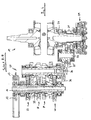
- FIG. 3 shows a side view of the engine / transmission unit and that of the in FIG. 1 shown side opposite, ie from the "right" side of the motorcycle 1 seen from.
- the clutch 29 an intermediate shaft 33, a transmission input shaft 34 and the coaxial with the swing arm 10 arranged transmission output shaft 35.
- a section line AA is shown.
- FIG. 4 shows a section through the motor / gear unit along the section line AA. How out FIG. 4 is seen, the torque supplied by the crankshaft 27 is transmitted via the clutch 29 to the primary pinion 31 and from the primary pinion 31 to an intermediate gear 35 ', which is arranged on the intermediate shaft 33.
- the intermediate gear 35 ' meshes with a transmission input pinion 36 disposed on the transmission input shaft 34.
- On the transmission input shaft 34 and the transmission output shaft 35 a plurality of switchable gear stages 37 - 40 are arranged, can be switched via the individual gears of the transmission 20. Depending on the gear engaged, the torque is transmitted via one of these gear stages 37-40 to the transmission output shaft 35 and from there via the transmission output pinion 12 to the chain 13 coupled to the rear wheel 3.
- the transmission output shaft 35 is a hollow shaft.
- the swing axle 10 is inserted through the transmission output shaft.
- the transmission output shaft 35 extends out of the transmission housing 41.
- the transmission output pinion 12 is arranged on the protruding portion of the transmission output shaft 35.
- the transmission output shaft 35 is mounted in the transmission housing 41 by means of two rolling bearings 42, 43.
- the swing arm 10 extends through the transmission output shaft 35 and thus through the transmission housing 41. Ends 44, 45 of the swing arm 10 are out of the gear housing 41 and are by means of two tapered roller bearings 46, 47, which are installed here in O arrangement, stored in the frame 5 of the motorcycle 1. In the swingarm axis 10 is therefore a "thru-axle" which allows easy mounting and dismounting of the rear swingarm 11.
- the rear swing arm 11 is clamped by means of a clamping connection 48 on the swing arm axis 10 and thus firmly positioned with respect to the swing arm axis 10. Since the rocker axis 10 is mounted in the frame 5 via the tapered roller bearings 46, 47, the rear wheel rocker 11 can be pivoted about the rocker axis 10 with respect to the frame 5.
- FIG. 6 shows a highly schematic representation of a motorcycle 1 according to the invention in a perspective view.
- the front end 18b of the shock absorber 18 is pivotally connected to the frame 5 via a transverse strut 49 interconnecting the two upper frame tubes 6, 6 '.
- the shallow arrangement of the suspension strut 18 results in a strong suspension strut progression, which considerably improves the handling behavior of the motorcycle in comparison with conventional motorcycles, in which the suspension strut is steepened.
- FIG. 7 shows the motorcycle the FIG. 6 in side view. Again, the flat mounting position of the strut 18 and the very simple construction of the frame 5 can be seen again very well. From the FIGS. 6 . 7 is also very good to recognize that the engine 19, the gear 20 and the radiator 21 can be used as a preassembled "power unit" during assembly of the motorcycle 1 from below into the frame 5, as in contrast to conventional motorcycles below the Engine 19 and the transmission 20 no frame tubes "to the rear" to the pivot point of the rear swing arm extend.
- this frame concept also allows the arrangement of a continuous cooler 21 below the lower frame tubes 7, 7 '.
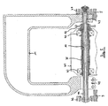
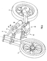
- FIG. 9 shows a side view of the rear swing arm 11 of the rear wheel 3 in an enlarged view.
Landscapes
- Engineering & Computer Science (AREA)
- Mechanical Engineering (AREA)
- Chemical & Material Sciences (AREA)
- Combustion & Propulsion (AREA)
- Transportation (AREA)
- Axle Suspensions And Sidecars For Cycles (AREA)
- Automatic Cycles, And Cycles In General (AREA)
- Arrangement Of Transmissions (AREA)
- General Details Of Gearings (AREA)
- Mechanical Operated Clutches (AREA)
- Transition And Organic Metals Composition Catalysts For Addition Polymerization (AREA)
Priority Applications (1)
| Application Number | Priority Date | Filing Date | Title |
|---|---|---|---|
| PL07007044T PL1813523T3 (pl) | 2005-07-14 | 2005-07-14 | Motocykl |
Applications Claiming Priority (1)
| Application Number | Priority Date | Filing Date | Title |
|---|---|---|---|
| EP05015290A EP1743832B1 (de) | 2005-07-14 | 2005-07-14 | Motorrad |
Related Parent Applications (1)
| Application Number | Title | Priority Date | Filing Date |
|---|---|---|---|
| EP05015290A Division EP1743832B1 (de) | 2005-07-14 | 2005-07-14 | Motorrad |
Publications (2)
| Publication Number | Publication Date |
|---|---|
| EP1813523A1 EP1813523A1 (de) | 2007-08-01 |
| EP1813523B1 true EP1813523B1 (de) | 2008-04-09 |
Family
ID=35453535
Family Applications (3)
| Application Number | Title | Priority Date | Filing Date |
|---|---|---|---|
| EP07007044A Expired - Lifetime EP1813523B1 (de) | 2005-07-14 | 2005-07-14 | Motorrad |
| EP05015290A Expired - Lifetime EP1743832B1 (de) | 2005-07-14 | 2005-07-14 | Motorrad |
| EP06762372.8A Active EP1901957B1 (de) | 2005-07-14 | 2006-07-04 | Fahrzeug, insbesondere motorrad, sowie motor-/getriebeeinheit für ein fahrzeug |
Family Applications After (2)
| Application Number | Title | Priority Date | Filing Date |
|---|---|---|---|
| EP05015290A Expired - Lifetime EP1743832B1 (de) | 2005-07-14 | 2005-07-14 | Motorrad |
| EP06762372.8A Active EP1901957B1 (de) | 2005-07-14 | 2006-07-04 | Fahrzeug, insbesondere motorrad, sowie motor-/getriebeeinheit für ein fahrzeug |
Country Status (10)
| Country | Link |
|---|---|
| US (1) | US9260153B2 (enExample) |
| EP (3) | EP1813523B1 (enExample) |
| JP (1) | JP2009501103A (enExample) |
| CN (1) | CN101155725A (enExample) |
| AT (2) | ATE377553T1 (enExample) |
| DE (2) | DE502005001901D1 (enExample) |
| ES (2) | ES2301157T3 (enExample) |
| PL (2) | PL1813523T3 (enExample) |
| TW (1) | TWI360500B (enExample) |
| WO (1) | WO2007006450A2 (enExample) |
Families Citing this family (13)
| Publication number | Priority date | Publication date | Assignee | Title |
|---|---|---|---|---|
| DE102007023962A1 (de) * | 2007-05-23 | 2008-11-27 | Ktm Sportmotorcycle Ag | Motorrad mit einem Fahrersattel und einem Kraftstofftank |
| ES2379343B1 (es) * | 2009-09-09 | 2013-08-20 | Implementing Technologies, S.L. | Motocicleta. |
| ES1072680Y (es) * | 2010-06-09 | 2010-12-28 | Creixell Jose Luis Belil | Motocicleta |
| JP5921812B2 (ja) * | 2011-02-25 | 2016-05-24 | 本田技研工業株式会社 | ハイブリッド車両用駆動装置 |
| DE102011085588B4 (de) | 2011-11-02 | 2014-01-23 | Bayerische Motoren Werke Aktiengesellschaft | Motorrad, insbesondere Motorroller |
| WO2017156020A1 (en) * | 2016-03-07 | 2017-09-14 | Misfit Industries (Us) Llc | Motorcycle monoshock systems |
| JP6790468B2 (ja) * | 2016-06-03 | 2020-11-25 | スズキ株式会社 | 鞍乗型車両 |
| DE102017213722A1 (de) * | 2017-08-08 | 2019-02-14 | Bayerische Motoren Werke Aktiengesellschaft | Antriebsvorrichtung für ein Motorrad |
| JP6369614B1 (ja) * | 2017-09-29 | 2018-08-08 | トヨタ自動車株式会社 | 車両用ケーシング |
| CN107738575A (zh) * | 2017-11-20 | 2018-02-27 | 重庆万虎机电有限责任公司 | 一种三轮摩托车的单缸发动机及其传动系统 |
| JP7260583B2 (ja) | 2021-03-31 | 2023-04-18 | 本田技研工業株式会社 | 鞍乗り型車両 |
| JP2023068985A (ja) * | 2021-11-04 | 2023-05-18 | ヤマハ発動機株式会社 | 車両 |
| CN116292671B (zh) * | 2023-04-23 | 2023-08-11 | 浙江春风动力股份有限公司 | 摩托车 |
Family Cites Families (57)
| Publication number | Priority date | Publication date | Assignee | Title |
|---|---|---|---|---|
| GB229782A (en) * | 1923-12-05 | 1925-03-05 | Francis Bracher Kerslake | Improvements in and relating to spring frames for motor cycles |
| GB558387A (en) | 1942-03-20 | 1944-01-04 | Aero Engines Ltd | Improvements in or relating to resilient suspension devices for vehicle wheels |
| FR1038140A (fr) | 1951-06-06 | 1953-09-25 | Système de suspension pour motocyclette | |
| GB1084453A (en) * | 1962-12-15 | 1967-09-20 | Standard Motor Co Ltd | Propulsion plant for a motor road vehicle |
| IT1061847B (it) * | 1976-06-25 | 1983-04-30 | Piaggio & C Spa | Ruota motrice con motore a combustione interna alloggiato nel proprio s*azio interno |
| JPS5335829A (en) | 1976-09-14 | 1978-04-03 | Honda Motor Co Ltd | Decompressing device to be used for motor bicycle and the like |
| FR2370625A1 (fr) | 1976-11-10 | 1978-06-09 | Houze Michel | Perfectionnements aux motocyclettes |
| JPS53100534A (en) * | 1977-02-14 | 1978-09-02 | Toyota Motor Corp | Automotive power transmitting system |
| GB1567774A (en) * | 1977-04-27 | 1980-05-21 | Rhind Tutt C | Motorcycles |
| GB1600934A (en) * | 1978-05-19 | 1981-10-21 | Silk Eng Derby Ltd | Motor cycles |
| DE3047069A1 (de) * | 1979-12-21 | 1981-10-08 | Porsche Design GmbH, 5700 Zell am See | "rahmen fuer einspurige fahrzeuge" |
| JPS5899548A (ja) * | 1981-12-10 | 1983-06-13 | Honda Motor Co Ltd | ベルト式無段変速機 |
| JPS58106249A (ja) * | 1981-12-19 | 1983-06-24 | Honda Motor Co Ltd | 可変容量フライホイ−ル |
| JPH0247575B2 (ja) * | 1982-02-26 | 1990-10-22 | Honda Motor Co Ltd | Nainenkikannotorukurimitsutasochi |
| JPS58102863A (ja) * | 1982-06-30 | 1983-06-18 | Honda Motor Co Ltd | 車両用パワ−ユニツト |
| US4603754A (en) * | 1983-08-10 | 1986-08-05 | Honda Giken Kogyo Kabushiki Kaisha | Drive system for engine-driven light vehicles |
| JPH0633739B2 (ja) * | 1984-10-31 | 1994-05-02 | スズキ株式会社 | 小型エンジンの始動装置 |
| JPH0730815B2 (ja) * | 1985-02-18 | 1995-04-10 | スズキ株式会社 | 副変速機 |
| JPS61241219A (ja) * | 1985-04-19 | 1986-10-27 | Honda Motor Co Ltd | 4輪駆動車の動力伝達装置 |
| JPH081251B2 (ja) * | 1985-07-19 | 1996-01-10 | ヤマハ発動機株式会社 | 鞍乗型車輛の変速装置 |
| US4774579A (en) * | 1986-10-30 | 1988-09-27 | Kucheran Duane A | Apparatus for quantifying video images of light beams |
| EP0290705A1 (en) * | 1987-05-11 | 1988-11-17 | Renato Roatta | Motorcycle |
| GB2220595B (en) * | 1988-07-13 | 1992-10-21 | Secr Defence | Hard surface composite parts. |
| DE69300628T2 (de) | 1992-05-04 | 1996-05-30 | Jose Luis Barcelona Belil Creixell | Radaufhängungs- und antriebseinheit für motorräder und dergleichen. |
| US5348112A (en) * | 1993-02-19 | 1994-09-20 | Works Performance Products, Inc. | Motorcycle height adjuster |
| DE69404782T2 (de) * | 1993-08-30 | 1997-12-04 | Honda Motor Co Ltd | Ölzufuhrkonstruktion für Anlassräder in einer Brennkraftmaschine |
| JPH08216961A (ja) * | 1995-02-03 | 1996-08-27 | Oehlins Racing Ab | 自動二輪車の後輪懸架装置 |
| DE19505800C2 (de) * | 1995-02-21 | 1998-10-15 | Gkn Viscodrive Gmbh | Vorrichtung zur Steuerung einer Kupplung |
| JP3613483B2 (ja) * | 1995-09-12 | 2005-01-26 | 本田技研工業株式会社 | 二・三輪車の後部構造 |
| AT403507B (de) * | 1995-12-22 | 1998-03-25 | Bombardier Rotax Gmbh | Schaltkupplung für ein motorrad |
| DE19803016A1 (de) * | 1997-01-31 | 1998-08-06 | Exedy Corp | Kupplungsdruckanordnung und Vorspannfeder hierin |
| JP4219017B2 (ja) * | 1997-10-21 | 2009-02-04 | 本田技研工業株式会社 | 車両用パワーユニット |
| JP3577925B2 (ja) * | 1997-12-25 | 2004-10-20 | スズキ株式会社 | 自動二輪車のフューエルタンク構造 |
| EP1001190B1 (en) * | 1998-11-13 | 2003-08-13 | Yutaka Giken Co., Ltd. | Transmission system for small-size vehicle |
| CA2289439C (en) * | 1998-11-13 | 2003-09-16 | Yutaka Giken Co., Ltd. | Transmitting system for small-sized vehicle |
| JP4326090B2 (ja) * | 1998-11-13 | 2009-09-02 | 株式会社ユタカ技研 | トルクコンバータ |
| JP2000230575A (ja) * | 1998-12-10 | 2000-08-22 | Nsk Warner Kk | 摩擦係合装置 |
| JP3855508B2 (ja) * | 1998-12-18 | 2006-12-13 | スズキ株式会社 | 自動二輪車のリザーブタンク配置構造 |
| JP4428591B2 (ja) * | 1999-09-04 | 2010-03-10 | 本田技研工業株式会社 | 自動2輪車の燃料タンク配置構造 |
| JP3705044B2 (ja) * | 1999-10-19 | 2005-10-12 | スズキ株式会社 | スクータ型車両 |
| US6487855B1 (en) * | 1999-11-11 | 2002-12-03 | Yutaka Giken Co., Ltd. | Torque converter |
| JP4381528B2 (ja) * | 1999-11-19 | 2009-12-09 | 本田技研工業株式会社 | 自動二輪車用伝動装置 |
| DE50001452D1 (de) | 2000-10-05 | 2003-04-17 | Ford Global Tech Inc | Doppelkupplung für ein Getriebe mit zwei Getriebeeingangswellen |
| JP2002122216A (ja) * | 2000-10-17 | 2002-04-26 | Denso Corp | クラッチ一体型プーリ |
| JP3815210B2 (ja) * | 2000-11-24 | 2006-08-30 | スズキ株式会社 | 車両用変速装置 |
| JP3879392B2 (ja) * | 2000-11-29 | 2007-02-14 | スズキ株式会社 | 自動二輪車の燃料タンク |
| ITMI20010686A1 (it) * | 2001-03-30 | 2002-09-30 | Vertemati Racing Di G Vertemat | Serbatoio per veicoli |
| WO2002094649A1 (en) | 2001-05-24 | 2002-11-28 | Spi S.R.L. | Chain drive system with two independent rings with intermediate double-pinion transmission element |
| US6755272B2 (en) | 2001-09-05 | 2004-06-29 | Henry Friesen | Oversize wheel assembly for a motorcycle |
| US6588530B2 (en) * | 2001-12-07 | 2003-07-08 | A.E. Technologies, Inc. | Motorcycle engine mounting system |
| CN100593077C (zh) * | 2002-04-08 | 2010-03-03 | 雅马哈发动机株式会社 | 发动机 |
| AU2003280444A1 (en) * | 2002-06-28 | 2004-01-19 | Kingsford Environmental (H.K.) Ltd. | Combined activated sludge-biofilm sequencing batch reactor and process |
| JP4104389B2 (ja) | 2002-07-17 | 2008-06-18 | 本田技研工業株式会社 | 単気筒エンジンのクラッチ断続検出装置 |
| JP2004098884A (ja) * | 2002-09-10 | 2004-04-02 | Honda Motor Co Ltd | 自動二輪車の後部構造 |
| DE10333431A1 (de) * | 2003-07-23 | 2005-02-10 | Zf Friedrichshafen Ag | Kupplungsanordnung in einem Automatgetriebe mit bauraumsparender Kühlmittelversorgung |
| US7104375B2 (en) * | 2003-07-31 | 2006-09-12 | Motoczysz Llc | Vehicle with separate gearbox clutch and back-torque-limiting slipper clutch |
| JP4260581B2 (ja) * | 2003-09-03 | 2009-04-30 | 本田技研工業株式会社 | 一方向クラッチ |
-
2005
- 2005-07-14 ES ES07007044T patent/ES2301157T3/es not_active Expired - Lifetime
- 2005-07-14 EP EP07007044A patent/EP1813523B1/de not_active Expired - Lifetime
- 2005-07-14 PL PL07007044T patent/PL1813523T3/pl unknown
- 2005-07-14 DE DE502005001901T patent/DE502005001901D1/de not_active Expired - Lifetime
- 2005-07-14 ES ES05015290T patent/ES2293436T3/es not_active Expired - Lifetime
- 2005-07-14 PL PL05015290T patent/PL1743832T3/pl unknown
- 2005-07-14 AT AT05015290T patent/ATE377553T1/de active
- 2005-07-14 AT AT07007044T patent/ATE391665T1/de active
- 2005-07-14 EP EP05015290A patent/EP1743832B1/de not_active Expired - Lifetime
- 2005-07-14 DE DE502005003686T patent/DE502005003686D1/de not_active Expired - Lifetime
-
2006
- 2006-07-04 WO PCT/EP2006/006478 patent/WO2007006450A2/de not_active Ceased
- 2006-07-04 EP EP06762372.8A patent/EP1901957B1/de active Active
- 2006-07-04 JP JP2008520751A patent/JP2009501103A/ja active Pending
- 2006-07-04 CN CNA2006800118399A patent/CN101155725A/zh active Pending
- 2006-07-10 TW TW095125087A patent/TWI360500B/zh active
-
2007
- 2007-10-25 US US11/976,619 patent/US9260153B2/en active Active
Also Published As
| Publication number | Publication date |
|---|---|
| WO2007006450A2 (de) | 2007-01-18 |
| TWI360500B (en) | 2012-03-21 |
| PL1743832T3 (pl) | 2010-01-29 |
| DE502005001901D1 (de) | 2007-12-20 |
| EP1901957A2 (de) | 2008-03-26 |
| ATE377553T1 (de) | 2007-11-15 |
| PL1813523T3 (pl) | 2010-01-29 |
| US20080223644A1 (en) | 2008-09-18 |
| TW200714517A (en) | 2007-04-16 |
| EP1743832B1 (de) | 2007-11-07 |
| DE502005003686D1 (de) | 2008-05-21 |
| US9260153B2 (en) | 2016-02-16 |
| ES2293436T3 (es) | 2008-03-16 |
| EP1813523A1 (de) | 2007-08-01 |
| WO2007006450A3 (de) | 2007-03-29 |
| ES2301157T3 (es) | 2008-06-16 |
| ATE391665T1 (de) | 2008-04-15 |
| CN101155725A (zh) | 2008-04-02 |
| JP2009501103A (ja) | 2009-01-15 |
| EP1743832A1 (de) | 2007-01-17 |
| EP1901957B1 (de) | 2020-05-13 |
Similar Documents
| Publication | Publication Date | Title |
|---|---|---|
| EP1813523B1 (de) | Motorrad | |
| DE2843561C2 (de) | Triebwerkaufhängung für Krafträder | |
| DE60121085T2 (de) | Keilriemengetriebe | |
| DE102009008012B4 (de) | Motorrad | |
| DE60223304T2 (de) | Brennkraftmaschine für ein Motorrrad | |
| DE3812431C2 (enExample) | ||
| DE102008011437B4 (de) | Hinterradaufhängung für einen Motorrad- und Schwenkarm-Anbringungsaufbau für ein Motorrad | |
| DE102010002975A1 (de) | Anordnungsstruktur für einen Behälter eines Fahrzeugs vom Satteltyp | |
| DE102007061034A1 (de) | Wellenangetriebenes Fahrzeug und Schwingenarmstruktur davon | |
| DE10125032B4 (de) | Hinterradaufhängung für ein Motorrrad | |
| DE602004000092T2 (de) | Kraftstoffeinspritzsystem bei einer Brennkraftmaschine für Kleinfahrzeuge | |
| DE102008039578A1 (de) | Motorrad | |
| DE102008061123A1 (de) | Motorrad | |
| DE602004012632T2 (de) | Anordnung zur Einrichtung eines hinteren Dämpfers | |
| DE102014116817B4 (de) | Einlasskanalvorrichtung für ein Motorrad | |
| DE102008063209A1 (de) | Antriebswellenvorrichtung | |
| DE10126105A1 (de) | Triebwerk für Motorrad | |
| DE2941435C2 (de) | Motorfahrzeug | |
| DE602004001185T2 (de) | Lenkungsdämpfer für Fahrzeug, und damit ausgestattetes Fahrzeug | |
| DE3710556A1 (de) | Rahmenkonstruktion fuer motorrad | |
| DE102017204199A1 (de) | Fahrzeuggetriebeaufbau | |
| DE102011002665B4 (de) | Schutzrohrstruktur für Kraftrad | |
| DE102007043720A1 (de) | Kraftrad | |
| DE102017204228A1 (de) | Getriebeaufbau für Fahrzeug | |
| DE102016124222A1 (de) | Fahrzeug des fahrsatteltyps |
Legal Events
| Date | Code | Title | Description |
|---|---|---|---|
| PUAI | Public reference made under article 153(3) epc to a published international application that has entered the european phase |
Free format text: ORIGINAL CODE: 0009012 |
|
| AC | Divisional application: reference to earlier application |
Ref document number: 1743832 Country of ref document: EP Kind code of ref document: P |
|
| AK | Designated contracting states |
Kind code of ref document: A1 Designated state(s): AT BE BG CH CY CZ DE DK EE ES FI FR GB GR HU IE IS IT LI LT LU LV MC NL PL PT RO SE SI SK TR |
|
| AX | Request for extension of the european patent |
Extension state: AL BA HR MK YU |
|
| 17P | Request for examination filed |
Effective date: 20070706 |
|
| 17Q | First examination report despatched |
Effective date: 20070910 |
|
| GRAP | Despatch of communication of intention to grant a patent |
Free format text: ORIGINAL CODE: EPIDOSNIGR1 |
|
| GRAS | Grant fee paid |
Free format text: ORIGINAL CODE: EPIDOSNIGR3 |
|
| GRAA | (expected) grant |
Free format text: ORIGINAL CODE: 0009210 |
|
| AC | Divisional application: reference to earlier application |
Ref document number: 1743832 Country of ref document: EP Kind code of ref document: P |
|
| AK | Designated contracting states |
Kind code of ref document: B1 Designated state(s): AT BE BG CH CY CZ DE DK EE ES FI FR GB GR HU IE IS IT LI LT LU LV MC NL PL PT RO SE SI SK TR |
|
| REG | Reference to a national code |
Ref country code: GB Ref legal event code: FG4D Free format text: NOT ENGLISH |
|
| REG | Reference to a national code |
Ref country code: CH Ref legal event code: EP |
|
| GBT | Gb: translation of ep patent filed (gb section 77(6)(a)/1977) |
Effective date: 20080415 |
|
| REG | Reference to a national code |
Ref country code: IE Ref legal event code: FG4D Free format text: LANGUAGE OF EP DOCUMENT: GERMAN |
|
| REF | Corresponds to: |
Ref document number: 502005003686 Country of ref document: DE Date of ref document: 20080521 Kind code of ref document: P |
|
| REG | Reference to a national code |
Ref country code: ES Ref legal event code: FG2A Ref document number: 2301157 Country of ref document: ES Kind code of ref document: T3 |
|
| PG25 | Lapsed in a contracting state [announced via postgrant information from national office to epo] |
Ref country code: SI Free format text: LAPSE BECAUSE OF FAILURE TO SUBMIT A TRANSLATION OF THE DESCRIPTION OR TO PAY THE FEE WITHIN THE PRESCRIBED TIME-LIMIT Effective date: 20080409 |
|
| PG25 | Lapsed in a contracting state [announced via postgrant information from national office to epo] |
Ref country code: PT Free format text: LAPSE BECAUSE OF FAILURE TO SUBMIT A TRANSLATION OF THE DESCRIPTION OR TO PAY THE FEE WITHIN THE PRESCRIBED TIME-LIMIT Effective date: 20080911 Ref country code: FI Free format text: LAPSE BECAUSE OF FAILURE TO SUBMIT A TRANSLATION OF THE DESCRIPTION OR TO PAY THE FEE WITHIN THE PRESCRIBED TIME-LIMIT Effective date: 20080409 Ref country code: BG Free format text: LAPSE BECAUSE OF FAILURE TO SUBMIT A TRANSLATION OF THE DESCRIPTION OR TO PAY THE FEE WITHIN THE PRESCRIBED TIME-LIMIT Effective date: 20080709 |
|
| PG25 | Lapsed in a contracting state [announced via postgrant information from national office to epo] |
Ref country code: PL Free format text: LAPSE BECAUSE OF FAILURE TO SUBMIT A TRANSLATION OF THE DESCRIPTION OR TO PAY THE FEE WITHIN THE PRESCRIBED TIME-LIMIT Effective date: 20080409 Ref country code: LV Free format text: LAPSE BECAUSE OF FAILURE TO SUBMIT A TRANSLATION OF THE DESCRIPTION OR TO PAY THE FEE WITHIN THE PRESCRIBED TIME-LIMIT Effective date: 20080409 |
|
| REG | Reference to a national code |
Ref country code: HU Ref legal event code: AG4A Ref document number: E003695 Country of ref document: HU |
|
| REG | Reference to a national code |
Ref country code: IE Ref legal event code: FD4D |
|
| PG25 | Lapsed in a contracting state [announced via postgrant information from national office to epo] |
Ref country code: IS Free format text: LAPSE BECAUSE OF FAILURE TO SUBMIT A TRANSLATION OF THE DESCRIPTION OR TO PAY THE FEE WITHIN THE PRESCRIBED TIME-LIMIT Effective date: 20080809 |
|
| ET | Fr: translation filed | ||
| PG25 | Lapsed in a contracting state [announced via postgrant information from national office to epo] |
Ref country code: SE Free format text: LAPSE BECAUSE OF FAILURE TO SUBMIT A TRANSLATION OF THE DESCRIPTION OR TO PAY THE FEE WITHIN THE PRESCRIBED TIME-LIMIT Effective date: 20080709 Ref country code: LT Free format text: LAPSE BECAUSE OF FAILURE TO SUBMIT A TRANSLATION OF THE DESCRIPTION OR TO PAY THE FEE WITHIN THE PRESCRIBED TIME-LIMIT Effective date: 20080409 Ref country code: IE Free format text: LAPSE BECAUSE OF FAILURE TO SUBMIT A TRANSLATION OF THE DESCRIPTION OR TO PAY THE FEE WITHIN THE PRESCRIBED TIME-LIMIT Effective date: 20080409 Ref country code: DK Free format text: LAPSE BECAUSE OF FAILURE TO SUBMIT A TRANSLATION OF THE DESCRIPTION OR TO PAY THE FEE WITHIN THE PRESCRIBED TIME-LIMIT Effective date: 20080409 |
|
| PLBE | No opposition filed within time limit |
Free format text: ORIGINAL CODE: 0009261 |
|
| STAA | Information on the status of an ep patent application or granted ep patent |
Free format text: STATUS: NO OPPOSITION FILED WITHIN TIME LIMIT |
|
| PG25 | Lapsed in a contracting state [announced via postgrant information from national office to epo] |
Ref country code: SK Free format text: LAPSE BECAUSE OF FAILURE TO SUBMIT A TRANSLATION OF THE DESCRIPTION OR TO PAY THE FEE WITHIN THE PRESCRIBED TIME-LIMIT Effective date: 20080409 Ref country code: RO Free format text: LAPSE BECAUSE OF FAILURE TO SUBMIT A TRANSLATION OF THE DESCRIPTION OR TO PAY THE FEE WITHIN THE PRESCRIBED TIME-LIMIT Effective date: 20080409 |
|
| 26N | No opposition filed |
Effective date: 20090112 |
|
| PG25 | Lapsed in a contracting state [announced via postgrant information from national office to epo] |
Ref country code: MC Free format text: LAPSE BECAUSE OF NON-PAYMENT OF DUE FEES Effective date: 20080731 |
|
| PG25 | Lapsed in a contracting state [announced via postgrant information from national office to epo] |
Ref country code: EE Free format text: LAPSE BECAUSE OF FAILURE TO SUBMIT A TRANSLATION OF THE DESCRIPTION OR TO PAY THE FEE WITHIN THE PRESCRIBED TIME-LIMIT Effective date: 20080409 |
|
| PG25 | Lapsed in a contracting state [announced via postgrant information from national office to epo] |
Ref country code: CY Free format text: LAPSE BECAUSE OF FAILURE TO SUBMIT A TRANSLATION OF THE DESCRIPTION OR TO PAY THE FEE WITHIN THE PRESCRIBED TIME-LIMIT Effective date: 20080409 |
|
| REG | Reference to a national code |
Ref country code: PL Ref legal event code: T3 |
|
| REG | Reference to a national code |
Ref country code: CH Ref legal event code: PL |
|
| PG25 | Lapsed in a contracting state [announced via postgrant information from national office to epo] |
Ref country code: LI Free format text: LAPSE BECAUSE OF NON-PAYMENT OF DUE FEES Effective date: 20090731 Ref country code: CH Free format text: LAPSE BECAUSE OF NON-PAYMENT OF DUE FEES Effective date: 20090731 |
|
| PG25 | Lapsed in a contracting state [announced via postgrant information from national office to epo] |
Ref country code: LU Free format text: LAPSE BECAUSE OF NON-PAYMENT OF DUE FEES Effective date: 20080714 Ref country code: BE Free format text: LAPSE BECAUSE OF NON-PAYMENT OF DUE FEES Effective date: 20080731 |
|
| PG25 | Lapsed in a contracting state [announced via postgrant information from national office to epo] |
Ref country code: TR Free format text: LAPSE BECAUSE OF FAILURE TO SUBMIT A TRANSLATION OF THE DESCRIPTION OR TO PAY THE FEE WITHIN THE PRESCRIBED TIME-LIMIT Effective date: 20080409 |
|
| PG25 | Lapsed in a contracting state [announced via postgrant information from national office to epo] |
Ref country code: GR Free format text: LAPSE BECAUSE OF FAILURE TO SUBMIT A TRANSLATION OF THE DESCRIPTION OR TO PAY THE FEE WITHIN THE PRESCRIBED TIME-LIMIT Effective date: 20080710 |
|
| REG | Reference to a national code |
Ref country code: FR Ref legal event code: PLFP Year of fee payment: 12 |
|
| REG | Reference to a national code |
Ref country code: FR Ref legal event code: PLFP Year of fee payment: 13 |
|
| REG | Reference to a national code |
Ref country code: FR Ref legal event code: PLFP Year of fee payment: 14 |
|
| P01 | Opt-out of the competence of the unified patent court (upc) registered |
Effective date: 20230731 |
|
| PGFP | Annual fee paid to national office [announced via postgrant information from national office to epo] |
Ref country code: NL Payment date: 20240722 Year of fee payment: 20 |
|
| PGFP | Annual fee paid to national office [announced via postgrant information from national office to epo] |
Ref country code: DE Payment date: 20240704 Year of fee payment: 20 |
|
| PGFP | Annual fee paid to national office [announced via postgrant information from national office to epo] |
Ref country code: GB Payment date: 20240723 Year of fee payment: 20 |
|
| PGFP | Annual fee paid to national office [announced via postgrant information from national office to epo] |
Ref country code: FR Payment date: 20240724 Year of fee payment: 20 |
|
| PGFP | Annual fee paid to national office [announced via postgrant information from national office to epo] |
Ref country code: ES Payment date: 20240816 Year of fee payment: 20 |
|
| PGFP | Annual fee paid to national office [announced via postgrant information from national office to epo] |
Ref country code: CZ Payment date: 20240628 Year of fee payment: 20 |
|
| PGFP | Annual fee paid to national office [announced via postgrant information from national office to epo] |
Ref country code: AT Payment date: 20240718 Year of fee payment: 20 |
|
| PGFP | Annual fee paid to national office [announced via postgrant information from national office to epo] |
Ref country code: PL Payment date: 20240702 Year of fee payment: 20 |
|
| PGFP | Annual fee paid to national office [announced via postgrant information from national office to epo] |
Ref country code: HU Payment date: 20240709 Year of fee payment: 20 |
|
| PGFP | Annual fee paid to national office [announced via postgrant information from national office to epo] |
Ref country code: IT Payment date: 20240731 Year of fee payment: 20 |
|
| REG | Reference to a national code |
Ref country code: DE Ref legal event code: R071 Ref document number: 502005003686 Country of ref document: DE |
|
| REG | Reference to a national code |
Ref country code: NL Ref legal event code: MK Effective date: 20250713 |
|
| PG25 | Lapsed in a contracting state [announced via postgrant information from national office to epo] |
Ref country code: CZ Free format text: LAPSE BECAUSE OF EXPIRATION OF PROTECTION Effective date: 20250714 |
|
| REG | Reference to a national code |
Ref country code: ES Ref legal event code: FD2A Effective date: 20250728 |
|
| REG | Reference to a national code |
Ref country code: GB Ref legal event code: PE20 Expiry date: 20250713 |
|
| REG | Reference to a national code |
Ref country code: AT Ref legal event code: MK07 Ref document number: 391665 Country of ref document: AT Kind code of ref document: T Effective date: 20250714 |
|
| PG25 | Lapsed in a contracting state [announced via postgrant information from national office to epo] |
Ref country code: ES Free format text: LAPSE BECAUSE OF EXPIRATION OF PROTECTION Effective date: 20250715 |