EP1703129A2 - Flügelzellenverdichter - Google Patents
Flügelzellenverdichter Download PDFInfo
- Publication number
- EP1703129A2 EP1703129A2 EP06013467A EP06013467A EP1703129A2 EP 1703129 A2 EP1703129 A2 EP 1703129A2 EP 06013467 A EP06013467 A EP 06013467A EP 06013467 A EP06013467 A EP 06013467A EP 1703129 A2 EP1703129 A2 EP 1703129A2
- Authority
- EP
- European Patent Office
- Prior art keywords
- hermetically sealed
- sealed container
- refrigerant
- cylinder
- rotary
- Prior art date
- Legal status (The legal status is an assumption and is not a legal conclusion. Google has not performed a legal analysis and makes no representation as to the accuracy of the status listed.)
- Granted
Links
Images


Classifications
-
- F—MECHANICAL ENGINEERING; LIGHTING; HEATING; WEAPONS; BLASTING
- F01—MACHINES OR ENGINES IN GENERAL; ENGINE PLANTS IN GENERAL; STEAM ENGINES
- F01C—ROTARY-PISTON OR OSCILLATING-PISTON MACHINES OR ENGINES
- F01C21/00—Component parts, details or accessories not provided for in groups F01C1/00 - F01C20/00
- F01C21/10—Outer members for co-operation with rotary pistons; Casings
- F01C21/104—Stators; Members defining the outer boundaries of the working chamber
- F01C21/108—Stators; Members defining the outer boundaries of the working chamber with an axial surface, e.g. side plates
-
- F—MECHANICAL ENGINEERING; LIGHTING; HEATING; WEAPONS; BLASTING
- F04—POSITIVE - DISPLACEMENT MACHINES FOR LIQUIDS; PUMPS FOR LIQUIDS OR ELASTIC FLUIDS
- F04C—ROTARY-PISTON, OR OSCILLATING-PISTON, POSITIVE-DISPLACEMENT MACHINES FOR LIQUIDS; ROTARY-PISTON, OR OSCILLATING-PISTON, POSITIVE-DISPLACEMENT PUMPS
- F04C23/00—Combinations of two or more pumps, each being of rotary-piston or oscillating-piston type, specially adapted for elastic fluids; Pumping installations specially adapted for elastic fluids; Multi-stage pumps specially adapted for elastic fluids
-
- F—MECHANICAL ENGINEERING; LIGHTING; HEATING; WEAPONS; BLASTING
- F01—MACHINES OR ENGINES IN GENERAL; ENGINE PLANTS IN GENERAL; STEAM ENGINES
- F01C—ROTARY-PISTON OR OSCILLATING-PISTON MACHINES OR ENGINES
- F01C21/00—Component parts, details or accessories not provided for in groups F01C1/00 - F01C20/00
- F01C21/08—Rotary pistons
- F01C21/0809—Construction of vanes or vane holders
- F01C21/0818—Vane tracking; control therefor
- F01C21/0827—Vane tracking; control therefor by mechanical means
- F01C21/0845—Vane tracking; control therefor by mechanical means comprising elastic means, e.g. springs
-
- F—MECHANICAL ENGINEERING; LIGHTING; HEATING; WEAPONS; BLASTING
- F04—POSITIVE - DISPLACEMENT MACHINES FOR LIQUIDS; PUMPS FOR LIQUIDS OR ELASTIC FLUIDS
- F04C—ROTARY-PISTON, OR OSCILLATING-PISTON, POSITIVE-DISPLACEMENT MACHINES FOR LIQUIDS; ROTARY-PISTON, OR OSCILLATING-PISTON, POSITIVE-DISPLACEMENT PUMPS
- F04C18/00—Rotary-piston pumps specially adapted for elastic fluids
- F04C18/30—Rotary-piston pumps specially adapted for elastic fluids having the characteristics covered by two or more of groups F04C18/02, F04C18/08, F04C18/22, F04C18/24, F04C18/48, or having the characteristics covered by one of these groups together with some other type of movement between co-operating members
- F04C18/34—Rotary-piston pumps specially adapted for elastic fluids having the characteristics covered by two or more of groups F04C18/02, F04C18/08, F04C18/22, F04C18/24, F04C18/48, or having the characteristics covered by one of these groups together with some other type of movement between co-operating members having the movement defined in group F04C18/08 or F04C18/22 and relative reciprocation between the co-operating members
- F04C18/356—Rotary-piston pumps specially adapted for elastic fluids having the characteristics covered by two or more of groups F04C18/02, F04C18/08, F04C18/22, F04C18/24, F04C18/48, or having the characteristics covered by one of these groups together with some other type of movement between co-operating members having the movement defined in group F04C18/08 or F04C18/22 and relative reciprocation between the co-operating members with vanes reciprocating with respect to the outer member
- F04C18/3562—Rotary-piston pumps specially adapted for elastic fluids having the characteristics covered by two or more of groups F04C18/02, F04C18/08, F04C18/22, F04C18/24, F04C18/48, or having the characteristics covered by one of these groups together with some other type of movement between co-operating members having the movement defined in group F04C18/08 or F04C18/22 and relative reciprocation between the co-operating members with vanes reciprocating with respect to the outer member the inner and outer member being in contact along one line or continuous surfaces substantially parallel to the axis of rotation
- F04C18/3564—Rotary-piston pumps specially adapted for elastic fluids having the characteristics covered by two or more of groups F04C18/02, F04C18/08, F04C18/22, F04C18/24, F04C18/48, or having the characteristics covered by one of these groups together with some other type of movement between co-operating members having the movement defined in group F04C18/08 or F04C18/22 and relative reciprocation between the co-operating members with vanes reciprocating with respect to the outer member the inner and outer member being in contact along one line or continuous surfaces substantially parallel to the axis of rotation the surfaces of the inner and outer member, forming the working space, being surfaces of revolution
-
- F—MECHANICAL ENGINEERING; LIGHTING; HEATING; WEAPONS; BLASTING
- F04—POSITIVE - DISPLACEMENT MACHINES FOR LIQUIDS; PUMPS FOR LIQUIDS OR ELASTIC FLUIDS
- F04C—ROTARY-PISTON, OR OSCILLATING-PISTON, POSITIVE-DISPLACEMENT MACHINES FOR LIQUIDS; ROTARY-PISTON, OR OSCILLATING-PISTON, POSITIVE-DISPLACEMENT PUMPS
- F04C23/00—Combinations of two or more pumps, each being of rotary-piston or oscillating-piston type, specially adapted for elastic fluids; Pumping installations specially adapted for elastic fluids; Multi-stage pumps specially adapted for elastic fluids
- F04C23/001—Combinations of two or more pumps, each being of rotary-piston or oscillating-piston type, specially adapted for elastic fluids; Pumping installations specially adapted for elastic fluids; Multi-stage pumps specially adapted for elastic fluids of similar working principle
-
- F—MECHANICAL ENGINEERING; LIGHTING; HEATING; WEAPONS; BLASTING
- F04—POSITIVE - DISPLACEMENT MACHINES FOR LIQUIDS; PUMPS FOR LIQUIDS OR ELASTIC FLUIDS
- F04C—ROTARY-PISTON, OR OSCILLATING-PISTON, POSITIVE-DISPLACEMENT MACHINES FOR LIQUIDS; ROTARY-PISTON, OR OSCILLATING-PISTON, POSITIVE-DISPLACEMENT PUMPS
- F04C23/00—Combinations of two or more pumps, each being of rotary-piston or oscillating-piston type, specially adapted for elastic fluids; Pumping installations specially adapted for elastic fluids; Multi-stage pumps specially adapted for elastic fluids
- F04C23/008—Hermetic pumps
-
- F—MECHANICAL ENGINEERING; LIGHTING; HEATING; WEAPONS; BLASTING
- F04—POSITIVE - DISPLACEMENT MACHINES FOR LIQUIDS; PUMPS FOR LIQUIDS OR ELASTIC FLUIDS
- F04C—ROTARY-PISTON, OR OSCILLATING-PISTON, POSITIVE-DISPLACEMENT MACHINES FOR LIQUIDS; ROTARY-PISTON, OR OSCILLATING-PISTON, POSITIVE-DISPLACEMENT PUMPS
- F04C29/00—Component parts, details or accessories of pumps or pumping installations, not provided for in groups F04C18/00 - F04C28/00
- F04C29/0042—Driving elements, brakes, couplings, transmissions specially adapted for pumps
-
- F—MECHANICAL ENGINEERING; LIGHTING; HEATING; WEAPONS; BLASTING
- F04—POSITIVE - DISPLACEMENT MACHINES FOR LIQUIDS; PUMPS FOR LIQUIDS OR ELASTIC FLUIDS
- F04C—ROTARY-PISTON, OR OSCILLATING-PISTON, POSITIVE-DISPLACEMENT MACHINES FOR LIQUIDS; ROTARY-PISTON, OR OSCILLATING-PISTON, POSITIVE-DISPLACEMENT PUMPS
- F04C29/00—Component parts, details or accessories of pumps or pumping installations, not provided for in groups F04C18/00 - F04C28/00
- F04C29/02—Lubrication; Lubricant separation
- F04C29/023—Lubricant distribution through a hollow driving shaft
-
- F—MECHANICAL ENGINEERING; LIGHTING; HEATING; WEAPONS; BLASTING
- F25—REFRIGERATION OR COOLING; COMBINED HEATING AND REFRIGERATION SYSTEMS; HEAT PUMP SYSTEMS; MANUFACTURE OR STORAGE OF ICE; LIQUEFACTION SOLIDIFICATION OF GASES
- F25B—REFRIGERATION MACHINES, PLANTS OR SYSTEMS; COMBINED HEATING AND REFRIGERATION SYSTEMS; HEAT PUMP SYSTEMS
- F25B9/00—Compression machines, plants or systems, in which the refrigerant is air or other gas of low boiling point
- F25B9/002—Compression machines, plants or systems, in which the refrigerant is air or other gas of low boiling point characterised by the refrigerant
- F25B9/008—Compression machines, plants or systems, in which the refrigerant is air or other gas of low boiling point characterised by the refrigerant the refrigerant being carbon dioxide
-
- F—MECHANICAL ENGINEERING; LIGHTING; HEATING; WEAPONS; BLASTING
- F04—POSITIVE - DISPLACEMENT MACHINES FOR LIQUIDS; PUMPS FOR LIQUIDS OR ELASTIC FLUIDS
- F04C—ROTARY-PISTON, OR OSCILLATING-PISTON, POSITIVE-DISPLACEMENT MACHINES FOR LIQUIDS; ROTARY-PISTON, OR OSCILLATING-PISTON, POSITIVE-DISPLACEMENT PUMPS
- F04C2210/00—Fluid
- F04C2210/26—Refrigerants with particular properties, e.g. HFC-134a
- F04C2210/261—Carbon dioxide (CO2)
-
- F—MECHANICAL ENGINEERING; LIGHTING; HEATING; WEAPONS; BLASTING
- F04—POSITIVE - DISPLACEMENT MACHINES FOR LIQUIDS; PUMPS FOR LIQUIDS OR ELASTIC FLUIDS
- F04C—ROTARY-PISTON, OR OSCILLATING-PISTON, POSITIVE-DISPLACEMENT MACHINES FOR LIQUIDS; ROTARY-PISTON, OR OSCILLATING-PISTON, POSITIVE-DISPLACEMENT PUMPS
- F04C2230/00—Manufacture
- F04C2230/20—Manufacture essentially without removing material
- F04C2230/23—Manufacture essentially without removing material by permanently joining parts together
- F04C2230/231—Manufacture essentially without removing material by permanently joining parts together by welding
-
- F—MECHANICAL ENGINEERING; LIGHTING; HEATING; WEAPONS; BLASTING
- F04—POSITIVE - DISPLACEMENT MACHINES FOR LIQUIDS; PUMPS FOR LIQUIDS OR ELASTIC FLUIDS
- F04C—ROTARY-PISTON, OR OSCILLATING-PISTON, POSITIVE-DISPLACEMENT MACHINES FOR LIQUIDS; ROTARY-PISTON, OR OSCILLATING-PISTON, POSITIVE-DISPLACEMENT PUMPS
- F04C2230/00—Manufacture
- F04C2230/60—Assembly methods
-
- F—MECHANICAL ENGINEERING; LIGHTING; HEATING; WEAPONS; BLASTING
- F04—POSITIVE - DISPLACEMENT MACHINES FOR LIQUIDS; PUMPS FOR LIQUIDS OR ELASTIC FLUIDS
- F04C—ROTARY-PISTON, OR OSCILLATING-PISTON, POSITIVE-DISPLACEMENT MACHINES FOR LIQUIDS; ROTARY-PISTON, OR OSCILLATING-PISTON, POSITIVE-DISPLACEMENT PUMPS
- F04C2240/00—Components
- F04C2240/30—Casings or housings
-
- F—MECHANICAL ENGINEERING; LIGHTING; HEATING; WEAPONS; BLASTING
- F04—POSITIVE - DISPLACEMENT MACHINES FOR LIQUIDS; PUMPS FOR LIQUIDS OR ELASTIC FLUIDS
- F04C—ROTARY-PISTON, OR OSCILLATING-PISTON, POSITIVE-DISPLACEMENT MACHINES FOR LIQUIDS; ROTARY-PISTON, OR OSCILLATING-PISTON, POSITIVE-DISPLACEMENT PUMPS
- F04C2240/00—Components
- F04C2240/60—Shafts
- F04C2240/601—Shaft flexion
-
- F—MECHANICAL ENGINEERING; LIGHTING; HEATING; WEAPONS; BLASTING
- F04—POSITIVE - DISPLACEMENT MACHINES FOR LIQUIDS; PUMPS FOR LIQUIDS OR ELASTIC FLUIDS
- F04C—ROTARY-PISTON, OR OSCILLATING-PISTON, POSITIVE-DISPLACEMENT MACHINES FOR LIQUIDS; ROTARY-PISTON, OR OSCILLATING-PISTON, POSITIVE-DISPLACEMENT PUMPS
- F04C2240/00—Components
- F04C2240/80—Other components
- F04C2240/803—Electric connectors or cables; Fittings therefor
-
- F—MECHANICAL ENGINEERING; LIGHTING; HEATING; WEAPONS; BLASTING
- F04—POSITIVE - DISPLACEMENT MACHINES FOR LIQUIDS; PUMPS FOR LIQUIDS OR ELASTIC FLUIDS
- F04C—ROTARY-PISTON, OR OSCILLATING-PISTON, POSITIVE-DISPLACEMENT MACHINES FOR LIQUIDS; ROTARY-PISTON, OR OSCILLATING-PISTON, POSITIVE-DISPLACEMENT PUMPS
- F04C2240/00—Components
- F04C2240/80—Other components
- F04C2240/806—Pipes for fluids; Fittings therefor
-
- F—MECHANICAL ENGINEERING; LIGHTING; HEATING; WEAPONS; BLASTING
- F04—POSITIVE - DISPLACEMENT MACHINES FOR LIQUIDS; PUMPS FOR LIQUIDS OR ELASTIC FLUIDS
- F04C—ROTARY-PISTON, OR OSCILLATING-PISTON, POSITIVE-DISPLACEMENT MACHINES FOR LIQUIDS; ROTARY-PISTON, OR OSCILLATING-PISTON, POSITIVE-DISPLACEMENT PUMPS
- F04C2250/00—Geometry
- F04C2250/10—Geometry of the inlet or outlet
- F04C2250/101—Geometry of the inlet or outlet of the inlet
-
- F—MECHANICAL ENGINEERING; LIGHTING; HEATING; WEAPONS; BLASTING
- F04—POSITIVE - DISPLACEMENT MACHINES FOR LIQUIDS; PUMPS FOR LIQUIDS OR ELASTIC FLUIDS
- F04C—ROTARY-PISTON, OR OSCILLATING-PISTON, POSITIVE-DISPLACEMENT MACHINES FOR LIQUIDS; ROTARY-PISTON, OR OSCILLATING-PISTON, POSITIVE-DISPLACEMENT PUMPS
- F04C2250/00—Geometry
- F04C2250/10—Geometry of the inlet or outlet
- F04C2250/102—Geometry of the inlet or outlet of the outlet
-
- F—MECHANICAL ENGINEERING; LIGHTING; HEATING; WEAPONS; BLASTING
- F04—POSITIVE - DISPLACEMENT MACHINES FOR LIQUIDS; PUMPS FOR LIQUIDS OR ELASTIC FLUIDS
- F04C—ROTARY-PISTON, OR OSCILLATING-PISTON, POSITIVE-DISPLACEMENT MACHINES FOR LIQUIDS; ROTARY-PISTON, OR OSCILLATING-PISTON, POSITIVE-DISPLACEMENT PUMPS
- F04C29/00—Component parts, details or accessories of pumps or pumping installations, not provided for in groups F04C18/00 - F04C28/00
- F04C29/02—Lubrication; Lubricant separation
- F04C29/028—Means for improving or restricting lubricant flow
-
- F—MECHANICAL ENGINEERING; LIGHTING; HEATING; WEAPONS; BLASTING
- F05—INDEXING SCHEMES RELATING TO ENGINES OR PUMPS IN VARIOUS SUBCLASSES OF CLASSES F01-F04
- F05C—INDEXING SCHEME RELATING TO MATERIALS, MATERIAL PROPERTIES OR MATERIAL CHARACTERISTICS FOR MACHINES, ENGINES OR PUMPS OTHER THAN NON-POSITIVE-DISPLACEMENT MACHINES OR ENGINES
- F05C2251/00—Material properties
- F05C2251/14—Self lubricating materials; Solid lubricants
-
- F—MECHANICAL ENGINEERING; LIGHTING; HEATING; WEAPONS; BLASTING
- F25—REFRIGERATION OR COOLING; COMBINED HEATING AND REFRIGERATION SYSTEMS; HEAT PUMP SYSTEMS; MANUFACTURE OR STORAGE OF ICE; LIQUEFACTION SOLIDIFICATION OF GASES
- F25B—REFRIGERATION MACHINES, PLANTS OR SYSTEMS; COMBINED HEATING AND REFRIGERATION SYSTEMS; HEAT PUMP SYSTEMS
- F25B2309/00—Gas cycle refrigeration machines
- F25B2309/06—Compression machines, plants or systems characterised by the refrigerant being carbon dioxide
- F25B2309/061—Compression machines, plants or systems characterised by the refrigerant being carbon dioxide with cycle highest pressure above the supercritical pressure
-
- F—MECHANICAL ENGINEERING; LIGHTING; HEATING; WEAPONS; BLASTING
- F25—REFRIGERATION OR COOLING; COMBINED HEATING AND REFRIGERATION SYSTEMS; HEAT PUMP SYSTEMS; MANUFACTURE OR STORAGE OF ICE; LIQUEFACTION SOLIDIFICATION OF GASES
- F25B—REFRIGERATION MACHINES, PLANTS OR SYSTEMS; COMBINED HEATING AND REFRIGERATION SYSTEMS; HEAT PUMP SYSTEMS
- F25B2500/00—Problems to be solved
- F25B2500/16—Lubrication
-
- Y—GENERAL TAGGING OF NEW TECHNOLOGICAL DEVELOPMENTS; GENERAL TAGGING OF CROSS-SECTIONAL TECHNOLOGIES SPANNING OVER SEVERAL SECTIONS OF THE IPC; TECHNICAL SUBJECTS COVERED BY FORMER USPC CROSS-REFERENCE ART COLLECTIONS [XRACs] AND DIGESTS
- Y10—TECHNICAL SUBJECTS COVERED BY FORMER USPC
- Y10S—TECHNICAL SUBJECTS COVERED BY FORMER USPC CROSS-REFERENCE ART COLLECTIONS [XRACs] AND DIGESTS
- Y10S417/00—Pumps
- Y10S417/902—Hermetically sealed motor pump unit
-
- Y—GENERAL TAGGING OF NEW TECHNOLOGICAL DEVELOPMENTS; GENERAL TAGGING OF CROSS-SECTIONAL TECHNOLOGIES SPANNING OVER SEVERAL SECTIONS OF THE IPC; TECHNICAL SUBJECTS COVERED BY FORMER USPC CROSS-REFERENCE ART COLLECTIONS [XRACs] AND DIGESTS
- Y10—TECHNICAL SUBJECTS COVERED BY FORMER USPC
- Y10T—TECHNICAL SUBJECTS COVERED BY FORMER US CLASSIFICATION
- Y10T29/00—Metal working
- Y10T29/49—Method of mechanical manufacture
- Y10T29/49229—Prime mover or fluid pump making
- Y10T29/49236—Fluid pump or compressor making
Definitions
- the present invention relates to a compressor including an electric element, and a compression element driven by the electric element in a container, its manufacturing method, a defroster of a refrigerant circuit, and a refrigeration unit.
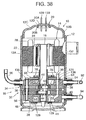
- refrigerant gas is supplied through a refrigerant introduction tube and a suction passage, and sucked from a suction port of a first rotary compression element into a low pressure chamber side of a cylinder (first cylinder).
- the refrigerant gas is then compressed by operations of a roller and a vane engaged with an eccentric part of a rotary shaft to become intermediate pressure, and discharged from a high pressure chamber side of the cylinder through a discharge port and a discharge muffler chamber into a hermetically sealed container.
- the refrigerant gas of the intermediate presser in the hermetically sealed container is sucked from a suction port of a second rotary compression element into a low pressure chamber side of a cylinder (second cylinder).
- the refrigerant gas is then subjected to second stage compression by operations of a roller and a vane engaged with an eccentric part of a rotary shaft to become one of a high temperature and high pressure.
- it is supplied from the high pressure chamber through the discharge port, the discharge passage and the discharge muffler chamber, and discharged from a refrigerant discharge tube to the refrigerant circuit.
- the refrigerant gas then flows into a radiator constituting the refrigerant circuit with the rotary compressor. After heat radiation, it is squeezed by an expansion valve, heat-absorbed by an evaporator, and sucked into the first rotary compression element. This cycle is repeated.
- the eccentric parts of the rotary shafts are provided to have a phase difference of 180°, and connected to each other by a connecting portion.
- a refrigerant having a large high and low pressure difference for example carbon dioxide (CO 2 ) as an example of carbon dioxide gas
- CO 2 carbon dioxide
- discharge refrigerant pressure reaches 12MPaG at the second rotary compression element, in which pressure becomes high.
- 8MPaG intermediate pressure
- Suction pressure of the first rotary compression element is about 4MPaG.
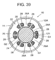
- the vane attached to such a rotary compressor is inserted in a groove provided in a radial direction of the cylinder so as to be freely moved in the radial direction of the cylinder.
- a spring hole (housing portion) opened to the outside of the cylinder is provided in a rear side of the vane (hermetically sealed container side), a coil spring (spring member) for always pressing the vane is inserted into the spring hole, an O ring is inserted into the spring hole from the opening outside the cylinder, and then sealed by a plug (pulling-out stopper) to prevent jumping-out of the spring.
- eccentric rotation of the roller applies a force of extruding the plug from the spring hole to the outside.
- the plug is also extruded by a pressure difference between inside and outside of the cylinder.
- the plug was pressed into the spring hole to be fixed to the cylinder.
- such pressure insertion deformed the cylinder to expand, forming a gap between it and a support member (bearing) for sealing the opening surface of the cylinder. Consequently, it was impossible to secure sealing in the cylinder, reducing performance.
- FIG. 20 shows in section a support member 291 according to a conventional art.
- a bearing 291A of a rotary shaft is erected on a center of the support member 291, and a bush 292 is attached in the bearing 291A.
- a discharge muffler chamber 293 is concaved in the support member 291 outside the bearing 291A, and the discharge muffler chamber 293 is sealed by a cover 294.
- the cover 294 has a peripheral part fixed on the support member 291 by a plurality of bolts.
- sealing by the cover 294 is an important problem.
- a gasket 296 is accordingly held between the cover 294 and the support member 291, but sealing is deteriorated because the center bearing 291A side is away from the bolt.
- a sealing surface 291B having a step was formed on a base of the bearing 291A, the gasket 296 was also held for sealing at this sealing surface 291B, a C ring 297 was attached to the bearing 291A, and an edge of the bearing 291A side of the cover 294 was pressed to the support member 291 side.
- each cylinder was fastened to the support member having the bearing by bolts arranged concentric circularly around the bearing. Consequently, there was a possibility of gas leakage from the cylinder.
- the connecting portion of the rotary shaft has a circular sectional shape coaxial to the rotary shaft, a sectional area to be physically secured is small, and the rotary shaft is easily deformed elastically.
- a section of the connecting portion was formed in a rugby ball shape, in which a thickness in a direction orthogonal to the eccentric direction was larger than that in the eccentric direction of both eccentric portions.
- the number of processing steps was increased in a cutting process of the rotary shaft, deteriorating productivity.
- the hermetically sealed container In the compressor of the hermetically sealed type, the hermetically sealed container must be subjected to airtightness testing in a completion test of a manufacturing process. Pressure for this test is set to about 4MPa in a normal compressor. However, if CO 2 is used as a refrigerant as described before, since pressure (intermediate pressure in the above-described case) of the hermetically sealed container becomes extremely high, test pressure of about 1OMPa as a design upper limit of intermediate pressure is required. Consequently, it was difficult to easily connect a compressed air generator for applying the test pressure into the hermetically sealed container to the compressor.
- an accumulator is attached to the hermetically sealed container.
- This accumulator is attached to a bracket welded to a side face of the hermetically sealed container by welding or a band, and held along the outside of the hermetically sealed container.
- the accumulator and a pile such as a refrigerant introduction tube may interfere with each other.
- the refrigerant introduction tubes of the first and second rotary compression elements are connected to the hermetically sealed container in positions adjacent to each other.
- FIG. 23 shows in section a terminal 299 of the conventional rotary compressor.
- the terminal 299 was fixed by welding to an upper surface of an end cap 298 exhibiting an asymmetrical sectional shape at a center as shown.
- a deformation amount of a region indicated by Z4 is 0.2 ⁇ m.
- a deformation amount of a region indicated by Z5 is larger, i.e., 0.5 ⁇ m, and a deformation amount of a region indicated by Z6 is increased further more to a maximum 0.9 ⁇ m.
- FIG. 25 shows in section a terminal 300 of another rotary compressor.
- the terminal 300 includes a circular glass portion 302 provided with an electric terminal 307, and a metal attaching portion 303 formed around it. This attaching portion 303 was welded to a peripheral edge of an attaching hole 306 formed in a hermetically sealed container 304.
- An opening surface of a cylinder of such a rotary compressor is sealed by a support member constituting a discharge muffler chamber inside and, on a center of the support member, a bearing of a rotary shaft of an electric element is provided. Then, by providing a carbon bush capable of maintaining good sliding performance even in insufficient oil supply, and having high wear resistance performance even with respect to a high PV value (load applied per unit area) during a high load between the bearing and the rotary shaft, durability of the rotary compressor can be greatly improved.
- a carbon bush was disadvantageous because a price was high, increasing competent costs.
- a thin cylinder is used for the rotary compression element to become high in pressure.
- a suction passage or a discharge passage cannot be formed within the thickness range of the cylinder, a suction passage and a discharge passage are formed on the support member side sealing the opening surface of the cylinder and having a bearing and, in the cylinder, the suction and discharge ports for communicating the suction passage and the discharge passage with the inside of the cylinder are obliquely formed.
- FIGS. 31 and 32 show a conventional processing method of such suction and discharge ports.
- a reference numeral 311 denotes a cylinder constituting a rotary compression element, 312 a suction port obliquely formed in the cylinder 311, and 313 a discharge port.
- an end mill ML1 having a flat tip is set obliquely to the cylinder 311, i.e., in a direction perpendicular to a slope of the suction port 312, and moved in an inclining direction of the suction port 312 as indicated by an arrow in FIG. 31, thereby forming a groove inclined with respect to the cylinder 311.
- the end mill ML1 is set obliquely to the cylinder 311, in this case, in an inclining direction of the discharge port 313, and extruded in the inclining direction of the discharge port 313 as indicated by an arrow in FIG. 32, thereby forming a notch inclined with respect to the cylinder 311.
- This refrigerant is discharged through the second rotary compression element.
- discharge pressure of the second rotary compression element is set equal to the suction pressure of the first rotary compression element. Consequently, a reversal phenomenon occurred in pressure between the discharge (high pressure) and the suction (intermediate pressure) of the second rotary compression element in the conventional case.
- pressure (high pressure) in the cylinder of the second rotary compression element is set higher than pressure (intermediate pressure) in the hermetically sealed container as the oil reservoir. Consequently, it was extremely difficult to supply oil from the oil hole of the rotary shaft into the cylinder by using the pressure difference, and lubrication was carried out only by the oil blended in the sucked refrigerant, causing a shortage of oil supply.
- the present invention was made to solve the foregoing problems inherent in the conventional art, and it is an object of the invention to provide a rotary compressor capable of preventing deterioration of performance following plug fixing carried out to prevent falling-off of a spring member.
- a rotary compressor of the present invention comprises an electric element, and a rotary compression element driven by the electric element, both components being provided in a hermetically sealed container, a cylinder constituting the rotary compression element, and a roller engaged with an eccentric portion formed in a rotary shaft of the electric element, and eccentrically rotated in the cylinder, a vane abutted on the roller to divide an inside of the cylinder into a low pressure chamber side and a high pressure chamber side, a spring member for always pressing the vane to the roller side, a housing portion of the spring member, formed in the cylinder, and opened to the vane side and the hermetically sealed container side, a plug positioned in the hermetically sealed container side of the spring member, and inserted into the housing portion to fit into a gap, and an O ring attached around the plug to seal a part between the plug and the housing portion.
- a space between the cylinder and the hermetically sealed container is set smaller than a distance from the O ring to an end of the
- a rotary compressor of the present invention comprises an electric element, first and second rotary compression elements driven by the electric element, these components being provided in a hermetically sealed container, gas compressed by the first rotary compression element being discharged into the hermetically sealed container, and the discharged gas of intermediate pressure being further compressed by the second rotary compression element, a cylinder constituting the second rotary compression element, a roller engaged with an eccentric portion formed in a rotary shaft of the electric element, and eccentrically rotated in the cylinder, a vane abutted on the roller to divide an inside of the cylinder into a low pressure chamber side and a high pressure chamber side, a spring member for always pressing the vane to the roller side, a housing portion of the spring member, formed in the cylinder, and opened to the vane side and the hermetically sealed container side, a plug positioned in the hermetically sealed container side of the spring member, and inserted into the housing portion to fit into a gap, and an O ring attached around the plug to seal a part between the plug and the housing portion
- the rotary compressor comprises the electric element, the rotary compression element driven by the electric element, both components being provided in the hermetically sealed container, the cylinder constituting the rotary compression element, the roller engaged with the eccentric portion formed in the rotary shaft of the electric element, and eccentrically rotated in the cylinder, the vane abutted on the roller to divide the inside of the cylinder into the low pressure chamber side and the high pressure chamber side, the spring member for always pressing the vane to the roller side, the housing portion of the spring member, formed in the cylinder, and opened to the vane side and the hermetically sealed container side, the plug positioned in the hermetically sealed container side of the spring member, and inserted into the housing portion to fit into a gap, and the O ring attached around the plug to seal a part between the plug and the housing portion.
- the invention is remarkably advantageous in a rotary compressor of a multistage compression type having an inside of a hermetically sealed container set to intermediate pressure in that compressor performance is maintained and a spring member is prevented from being pulled out when CO 2 gas is used as a refrigerant, intermediate pressure is set in the hermetically sealed container, and pressure in a second rotary compression element becomes extremely high.
- a rotary compressor of the present invention comprises an electric element, a rotary compression element driven by the electric element, both components being provided in a hermetically sealed container, a cylinder constituting the rotary compression element, a roller engaged with an eccentric portion formed in a rotary shaft of the electric element, and eccentrically rotated in the cylinder, a support member adapted to seal an opening surface of the cylinder, and provided with a bearing of the rotary shaft, a vane abutted on the roller to divide an inside of the cylinder into a low pressure chamber side and a high pressure chamber side, a spring member for always pressing the vane to the roller side, a housing portion of the spring member, formed in the cylinder, and opened to the vane side and the hermetically sealed container side, and a plug positioned in the hermetically sealed container side of the spring member, and pressed into and fixed in the housing portion.
- the support member of a part corresponding to the plug includes a roll off concaved in a direction away from the cylinder.
- a rotary compressor of the present invention comprises an electric element, first and second rotary compression elements driven by the electric element, these components being provided in a hermetically sealed container, gas compressed by the first compression element being discharged into the hermetically sealed container, and the discharged gas of intermediate pressure being further compressed by the second rotary compression element, a cylinder constituting the second rotary compression element, a roller engaged with an eccentric portion formed in a rotary shaft of the electric element, and eccentrically rotated in the cylinder, a vane abutted on the roller to divide an inside of the cylinder into a low pressure chamber side and a high pressure chamber side, a support member adapted to seal an opening surface of the cylinder, and provided with a bearing of the rotary shaft, a spring member for always pressing the vane to the roller side, a housing portion of the spring member, formed in the cylinder, and opened to the vane side and the hermetically sealed container side, and a plug positioned in the hermetically sealed container side of the spring member, and pressed into and fixed in the
- the rotary compressor comprises the electric element, the rotary compression element driven by the electric element, both components being provided in a hermetically sealed container, the cylinder constituting the rotary compression element, the roller engaged with the eccentric portion formed in the rotary shaft of the electric element, and eccentrically rotated in the cylinder, the support member adapted to seal the opening surface of the cylinder, and provided with the bearing of the rotary shaft, the vane abutted on the roller to divide the inside of the cylinder into the low pressure chamber side and the high pressure chamber side, the spring member for always pressing the vane to the roller side, the housing portion of the spring member, formed in the cylinder, and opened to the vane side and the hermetically sealed container side, and the plug positioned in the hermetically sealed container side of the spring member, and pressed into and fixed in the housing portion.
- the support member of a part corresponding to the plug includes the roll off concaved in a direction away from the cylinder.
- the invention is remarkably advantageous in a rotary compressor of a multistage compression type having an inside of a hermetically sealed container set to intermediate pressure in that compressor performance is maintained and a spring member is prevented from being pulled out when CO 2 gas is used as a refrigerant, intermediate pressure is set in the hermetically sealed container, and pressure in a second rotary compression element becomes extremely high.
- An object of the present invention is to smoothly and surely supply oil into a cylinder of a second rotary compression element of a second stage in a rotary compressor of an internal intermediate pressure multistage compression type.
- a rotary compressor comprises an electric element, first and second rotary compression elements driven by the electric element, these components being provided in a hermetically sealed container, gas compressed by the first rotary compression element being discharged into the hermetically sealed container, and the discharged gas of intermediate pressure being further compressed by the second rotary compression element, cylinders constituting the respective rotary compression elements, an intermediate diaphragm provided between the cylinders to partition each rotary compression element, a support member adapted to seal an opening surface of each cylinder, and provided with a bearing of a rotary shaft, and an oil hole formed in the rotary shaft.
- the intermediate diaphragm includes an oil supply path for communicating the oil hole with a suction side of the second rotary compression element.
- the rotary compressor comprises the electric element, the first and second rotary compression elements driven by the electric element, these components being provided in a hermetically sealed container, gas compressed by the first rotary compression element being discharged into the hermetically sealed container, and the discharged gas of intermediate pressure being further compressed by the second rotary compression element, the cylinders constituting the respective rotary compression elements, the intermediate diaphragm provided between the cylinders to partition each rotary compression element, the support member adapted to seal the opening surface of each cylinder, and provided with the bearing of the rotary shaft, and the oil hole formed in the rotary shaft.
- the intermediate diaphragm includes the oil supply path for communicating the oil hole with the suction side of the second rotary compression element.
- the oil supply path is constructed by boring a through-hole in the intermediate diaphragm to communicate an outer peripheral surface with an inner peripheral surface of the rotary shaft side, and a communication hole for sealing an opening of the through-hole on the outer peripheral side, and communicating the through-hole with the suction side is bored on the cylinder for constituting the second rotary compression element.
- the oil supply is constructed by boring the through-hole in the intermediate diaphragm to communicate the outer peripheral surface with the inner peripheral surface of the rotary shaft side, and the communication hole for sealing the opening of the through-hole on the outer peripheral surface side, and communicating the through-hole with the suction side is bored in the cylinder for constituting the second rotary compression element.
- An object of the present invention is to carry out sure cover sealing for sealing a discharge muffler chamber of a second rotary compression element by simple constitution in a rotary compressor of an internal intermediate pressure multistage type.
- a rotary compressor of the present invention comprises an electric element, first and second rotary compression elements driven by the electric element, these components being provided in a hermetically sealed container, CO 2 refrigerant gas compressed by the first rotary compression element being discharged into the hermetically sealed container, and the discharged refrigerant gas of intermediate pressure being further compressed by the second rotary compression element, a cylinder constituting the second rotary compression element, a support member adapted to seal an opening surface of the cylinder, and provided with a bearing of a rotary shaft erected on a center part, a discharge muffler chamber formed in the support member outside the bearing, and communicated with an inside of the cylinder, a cover having a peripheral part fixed to the support member by a bolt to seal an opening of the discharge muffler chamber, a gasket held between the cover and the support member, and an O ring provided between an inner peripheral end surface of the cover and an outer peripheral surface of the bearing.
- the rotary compressor comprises the electric element, the first and second rotary compression elements driven by the electric element, these components being provided in the hermetically sealed container, CO 2 refrigerant gas compressed by the first rotary compression element being discharged into the hermetically sealed container, and the discharged refrigerant gas of intermediate pressure being further compressed by the second rotary compression element, the cylinder constituting the second rotary compression element, the support member adapted to seal the opening surface of the cylinder, and provided with the bearing of the rotary shaft erected on the center part, the discharge muffler chamber formed in the support member outside the bearing, and communicated with the inside of the cylinder, the cover having the peripheral part fixed to the support member by the bolt to seal the opening of the discharge muffler chamber, the gasket held between the cover and the support member, and the O ring provided between the inner peripheral end surface of the cover and the outer peripheral surface of the bearing.
- An object of the present invention is to set a thickness dimension of a cover for sealing a discharge muffler chamber of a second rotary compression element to an optimal value in a rotary compressor of an internal intermediate pressure multistage compression type.
- a rotary compressor of the present invention comprises an electric element, first and second rotary compression elements driven by the electric element, these components being provided in a hermetically sealed container, CO 2 refrigerant gas compressed by the first rotary compression element being discharged into the hermetically sealed container, and the discharged refrigerant gas of intermediate pressure being further compressed by the second rotary compression element, a cylinder constituting the second rotary compression element, a support member adapted to seal an opening surface of the cylinder on the electric element side, and provided with a bearing of a rotary shaft erected on a center part, a discharge muffler chamber formed in the support member outside the bearing, and communicated with an inside of the cylinder, and a cover attached to the support member to seal an opening of the discharge muffler chamber.
- a thickness dimension of the cover is set to ⁇ 2 mm to ⁇ 10 mm.
- a thickness of the cover is set to 6 mm.
- the rotary compressor comprises the electric element, the first and second rotary compression elements driven by the electric element, these components being provided in the hermetically sealed container, CO 2 refrigerant gas compressed by the first rotary compression element being discharged into the hermetically sealed container, and the discharged refrigerant gas of intermediate pressure being further compressed by the second rotary compression element, the cylinder constituting the second rotary compression element, the support member adapted to seal the opening surface of the cylinder on the electric element side, and provided with the bearing of the rotary shaft erected on the center part, the discharge muffler chamber formed in the support member outside the bearing, and communicated with the inside of the cylinder, and the cover attached to the support member to seal the opening of the discharge muffler chamber.
- the thickness dimension of the cover is set to ⁇ 2 mm to ⁇ 10 mm, and the thickness of the cover is set to 6 mm.
- the cover has a peripheral part fixed to the support member by a bolt, a gasket is held between the cover and the support member, and an O ring is provided between an inner peripheral end surface of the cover and an outer surface of the bearing.
- the cover has the peripheral part fixed to the support member by the bolt, the gasket is held between the cover and the support member, and the O ring is provided between the inner peripheral end surface of the cover and the outer surface of the bearing.
- An object of the present invention is to effectively prevent gas leakage from a cylinder in a rotary compressor using CO 2 as a refrigerant.
- a rotary compressor of the present invention comprises an electric element, first and second rotary compression elements driven by the electric element, these components being provided in a hermetically sealed container, CO 2 refrigerant gas compressed by the first rotary compression element being discharged into the hermetically sealed container, and the discharged refrigerant gas of intermediate pressure being further compressed by the second rotary compression element, a cylinder constituting each rotary compression element, a support member adapted to seal an opening surface of each cylinder, and provided with a bearing of a rotary shaft erected on a center, a discharge muffler chamber formed in the support member outside the bearing, and communicated with an inside of the cylinder, a cover attached to the support member to seal an opening of the discharge muffler chamber.
- each cylinder, each support member and each cover are fastened by a plurality of main bolts, and each cylinder and each support member are fastened by auxiliary bolts located outside the main bolts.
- the rotary compressor comprises the electric element, the first and second rotary compression elements driven by the electric element, these components being provided in the hermetically sealed container, CO 2 refrigerant gas compressed by the first rotary compression element being discharged into the hermetically sealed container, and the discharged refrigerant gas of intermediate pressure being further compressed by the second rotary compression element, the cylinder constituting each rotary compression element, the support member adapted to seal the opening surface of each cylinder, and provided with the bearing of the rotary shaft erected on the center, the discharge muffler chamber formed in the support member outside the bearing, and communicated with the inside of the cylinder, the cover attached to the support member to seal the opening of the discharge muffler chamber.
- Each cylinder, each support member and each cover are fastened by the plurality of main bolts, and each cylinder and each support member are fastened by the auxiliary bolts located outside the main bolts.
- the rotary compressor of the invention further comprises a roller engaged with an eccentric portion formed in the rotary shaft of the electric element, and eccentrically rotated in the cylinder constituting the second rotary compression element, a vane abutted on the roller to divide an inside of the cylinder into a low pressure chamber side and a high pressure chamber side, and a guide groove formed in the cylinder to house the vane.
- the auxiliary bolts are positioned near the guide groove.
- the rotary compressor further comprises the roller engaged with the eccentric portion formed in the rotary shaft of the electric element, and eccentrically rotated in the cylinder constituting the second rotary compression element, the vane abutted on the roller to divide the inside of the cylinder into the low pressure chamber side and the high pressure chamber side, and the guide groove formed in the cylinder to house the vane.
- the auxiliary bolts are positioned near the guide groove.
- An object of the present invention is to provide a rotary compressor capable of improving workability while increasing strength of a rotary shaft.
- a rotary compressor comprises an electric element, first and second rotary compression elements driven by the electric element, these components being provided in a hermetically sealed container, and gas compressed by the first rotary compression element being compressed by the second rotary compression element, first and second cylinders constituting the first and second rotary compression elements, and first and second rollers engaged with eccentric portions formed in a rotary shaft of the electric element to have a phase difference of 180°, and eccentrically rotated in the respective cylinders.
- a section of a connecting portion for connecting both eccentric portions with each other is formed in a shape having a thickness larger in a direction orthogonal to an eccentric direction than that in the eccentric direction of each of the eccentric portions, a side face of the connecting portion in the eccentric direction side of the first eccentric portion is formed in a circular-arc shape of the same center as that of the second eccentric portion, and a side face in the eccentric direction of the second eccentric portion is formed in a circular-arc shape of the same center as that of the first eccentric portion.
- the rotary compressor comprises the electric element, the rotary compression element driven by the electric element, these components being provided in the hermetically sealed container, and gas compressed by the first rotary compression element being compressed by the second rotary compression element, the first and second cylinders constituting the first and second rotary compression elements, and the first and second rollers engaged with the eccentric portions formed in the rotary shaft of the electric element to have a phase difference of 180°, and eccentrically rotated in the respective cylinders.
- the section of the connecting portion for connecting both eccentric portions with each other is formed in the shape having the thickness larger in the direction orthogonal to the eccentric direction than that in the eccentric direction of each of the eccentric portions.
- the side face of the connecting portion in the eccentric direction side of the first eccentric portion is formed in a circular-arc shape of the same center as that of the second eccentric portion
- the side face in the eccentric direction of the second eccentric portion is formed in a circular-arc shape of the same center as that of the first eccentric portion. Accordingly, it is possible to reduce the number of times of changing chucking positions during cutting of the rotary shafts having eccentric portions and connecting portions. Therefore, it is possible to reduce the number of processing steps, and costs by improved productivity.
- An object of the present invention is to provide a hermetically sealed compressor capable of facilitating airtightness testing even when CO 2 is used as a refrigerant and pressure in a hermetically sealed container becomes high.
- a hermetically sealed compressor comprises an electric element, a compression element driven by the electric element, both components being provided in a hermetically sealed container, a CO 2 refrigerant sucked from a refrigerant introduction tube being compressed by the compression element, discharged into the hermetically sealed container, and then discharged outside from a refrigerant discharge tube, a sleeve provided in the hermetically sealed container, to which the refrigerant introduction tube and the refrigerant discharge tube are connected, and a flange formed around an outer surface of the sleeve to engage a coupler for pipe connection.
- the hermetically sealed compressor comprises the electric element, the compression element driven by the electric element, both components being provided in the hermetically sealed container, a CO 2 refrigerant sucked from the refrigerant introduction tube being compressed by the compression element, discharged into the hermetically sealed container, and then discharged outside from the refrigerant discharge tube, the sleeve provided in the hermetically sealed container, to which the refrigerant introduction tube and the refrigerant discharge tube are connected, and the flange formed around an outer surface of the sleeve to engage the coupler for pipe connection.
- the flange it is possible to easily engaged and connect the coupler provided for piping from a compressed air generator to the sleeve of the hermetically sealed container.
- a hermetically sealed compressor of the present invention comprises an electric element, a compression element driven by the electric element, both components being provided in a hermetically sealed container, a CO 2 refrigerant sucked from a refrigerant introduction tube being compressed by the compression element, discharged into the hermetically sealed container, and then discharged outside from a refrigerant discharge tube, a sleeve provided in the hermetically sealed container, to which the refrigerant introduction tube and the refrigerant discharge tube are connected, and a screw groove formed for pipe connection around an outer surface of the sleeve.
- the hermetically sealed compressor comprises the electric element, the compression element driven by the electric element, both components being provided in the hermetically sealed container, a CO 2 refrigerant sucked from the refrigerant introduction tube being compressed by the compression element, discharged into the hermetically sealed container, and then discharged outside from the refrigerant discharge tube, the sleeve provided in the hermetically sealed container, to which the refrigerant introduction tube and the refrigerant discharge tube are connected, and the screw groove formed for pipe connection around the outer surface of the sleeve.
- this screw groove a pipe from a compressed air generator can be easily connected to the sleeve of the hermetically sealed container.
- a hermetically sealed compressor of the present invention comprises an electric element, a compression element driven by the electric element, both components being provided in a hermetically sealed container, a CO 2 refrigerant sucked from a refrigerant introduction tube being compressed by the compression element, discharged into the hermetically sealed container, and then discharged outside from a refrigerant discharge tube, a plurality of sleeves provided in the hermetically sealed container, to which the refrigerant introduction tube and the refrigerant discharge tube are connected, a flange formed around an outer surface of one of adjacent sleeves to engage a coupler for pipe connection, and a screw groove formed for pipe connection around an outer surface of the other sleeve.
- the hermetically sealed compressor comprises the electric element, the compression element driven by the electric element, both components being provided in the hermetically sealed container, a CO 2 refrigerant sucked from the refrigerant introduction tube being compressed by the compression element, discharged into the hermetically sealed container, and then discharged outside from the refrigerant discharge tube, the plurality of sleeves provided in the hermetically sealed container, to which the refrigerant introduction tube and the refrigerant discharge tube are connected, the flange formed around the outer surface of one of adjacent sleeves to engage the coupler for pipe connection, and the screw groove formed for pipe connection around the outer surface of the other sleeve.
- the coupler provided in the pipe from the compressed air generator can be easily engaged and connected to one of the sleeves of the hermetically sealed container.
- the screw groove By using the screw groove, the pipe from the compressed air generator can be easily connected to the other sleeve of the hermetically sealed container. Therefore, it is possible to finish airtightness testing in a manufacturing process of the hermetically sealed compressor of high internal pressure within a short time.
- the flange is formed in one of the adjacent sleeves, and the screw groove is formed in the other sleeve, no couplers having relatively large dimensions are connected adjacently to each other and, even in the case of a narrow space between the sleeves, it is possible to connect a plurality of pipes from the compressed air generator by using the narrow space.
- An object of the present invention is to provide a compressor capable of easily dealing with a capacity change of an accumulator.
- a compressor comprises an electric element, a compression element driven by the electric element, both components being provided in a container, a container side bracket provided in a side face of the container, an accumulator, and an accumulator side bracket, to which the accumulator is attached.
- the accumulator side bracket to the container side bracket, the accumulator is attached to the container through both brackets.
- the accumulator side bracket is attached to a center or a position of a center of gravity of the accumulator, or in the vicinity thereof.
- the compressor comprises the electric element, the compression element driven by the electric element, both components being provided in the container, the container side bracket provided in the side face of the container, the accumulator, and the accumulator side bracket, to which the accumulator is attached.
- the accumulator side bracket By fixing the accumulator side bracket to the container side bracket, the accumulator is attached to the container through both brackets.
- the accumulator side bracket is attached to its center or a position of a center of gravity, or in the vicinity thereof, and the accumulator can be held on the center or the position of a center of gravity of the accumulator, or in the vicinity thereof.
- the accumulator side bracket is attached to its center or a position of a center of gravity, or in the vicinity thereof, and the accumulator can be held on the center or the position of a center of gravity of the accumulator, or in the vicinity thereof.
- An object of the present invention is to provide a compressor capable of increasing space efficiency without any mutual interferences between first and second refrigerant introduction tubes.
- a compressor of the present invention comprises an electric element, first and second compression elements driven by the electric element, these components being provided in a hermetically sealed container, a refrigerant introduction tube for introducing a refrigerant to the first compression element, a refrigerant tube for introducing refrigerant gas compressed by the first compression element to the second compression element, and a refrigerant tube for discharging high pressure gas compressed by the second compression element.
- the refrigerant tubes of the first and second compression elements are connected to the hermetically sealed container in adjacent positions, and laid around in opposing directions from the hermetically sealed container.
- the refrigerant tube of the first compression element is connected to the hermetically sealed container in a position below the refrigerant tube of the second compression element, an accumulator is arranged above a connecting position of each refrigerant tube to the hermetically sealed container, and the accumulator is connected to the refrigerant tube for introducing the refrigerant to the first compression element.
- the compressor comprises the electric element, first and second compression elements driven by the electric element, these components being provided in the hermetically sealed container, the refrigerant introduction tube for introducing a refrigerant to the first compression element, the refrigerant tube for introducing refrigerant gas compressed by the first compression element to the second compression element, and the refrigerant tube for discharging high pressure gas compressed by the second compression element.
- the refrigerant tubes of the first and second compression elements are connected to the hermetically sealed container in the adjacent positions, and laid around in opposing directions from the hermetically sealed container. Thus, it is possible to lay around the refrigerant tubes in limited spaces without any mutual interferences.
- the refrigerant tube of the first compression element is connected to the hermetically sealed container in the position below the refrigerant tube of the second compression element, the accumulator is arranged above the connecting position of each refrigerant tube to the hermetically sealed container, and the accumulator is connected to the refrigerant tube for introducing the refrigerant to the first compression element.
- the position of the accumulator is lowered to a lowest limit to approach the refrigerant tube of the second compression element while mutual interferences between the two refrigerant tubes are prevented.
- a compressor of the present invention comprises an electric element, and first and second compression elements driven by the electric element, these components being provided in a hermetically sealed container, a first refrigerant introduction tube for sucking refrigerant gas, the refrigerant gas being compressed by the first compression element, and discharged into the hermetically sealed container, and a second refrigerant introduction tube located outside the hermetically sealed container for sucking the discharged refrigerant gas of intermediate pressure, the refrigerant gas being compressed by the second compression element.
- the first and second refrigerant introduction tubes are connected to the hermetically sealed container in adjacent positions, and laid around in opposing directions from the hermetically sealed container.
- the first refrigerant tube is connected to the hermetically sealed container in a position below the second refrigerant tube, an accumulator is arranged above a connecting position of each refrigerant introduction tube to the hermetically sealed container, and the accumulator is connected to the first refrigerant introduction.
- the compressor comprises the electric element, the first and second compression elements driven by the electric element, these components being provided in the hermetically sealed container, the first refrigerant introduction tube for sucking refrigerant gas, the refrigerant gas being compressed by the first compression element, and discharged into the hermetically sealed container, and the second refrigerant introduction tube located outside the hermetically sealed container for sucking the discharged refrigerant gas of intermediate pressure, the refrigerant gas being compressed by the second compression element.
- the first and second refrigerant introduction tubes are connected to the hermetically sealed container in adjacent positions, and laid around in opposing directions from the hermetically sealed container. Thus, it is possible to lay around the refrigerant introduction tubes in limited spaces without any mutual interferences.
- the first refrigerant tube is connected to the hermetically sealed container in a position below the second refrigerant tube
- the accumulator is arranged above a connecting position of each refrigerant introduction tube to the hermetically sealed container, and the accumulator is connected to the first refrigerant introduction.
- a position of the accumulator can be lowered to a lowest limit to approach the second refrigerant introduction tube while mutual interferences between the two refrigerant introduction tubes are prevented.
- An object of the present invention is to provide a hermetically sealed compressor capable of preventing inconvenience caused by end cap deformation.
- a hermetically sealed compressor of the present invention comprises an electric element, a compression element driven by the electric element, both components being provided in a hermetically sealed container, a refrigerant being compressed by the compression element, and discharged into the hermetically sealed container, a terminal attached to an end cap of the hermetically sealed container, and a step having a predetermined curvature formed by seat pushing in the end cap around the terminal.
- the hermetically sealed compressor comprises the electric element, the compression element driven by the electric element, both components being provided in a hermetically sealed container, a refrigerant being compressed by the compression element, and discharged into the hermetically sealed container, the terminal attached to the end cap of the hermetically sealed container, and the step having a predetermined curvature formed by seat pushing in the end cap around the terminal.
- rigidity of the end cap in the vicinity of the terminal is increased.
- pressure in the hermetically sealed container becomes high as in the case of compressing CO 2 gas as a refrigerant, a deformation amount of the end cap by inner pressure of the hermetically sealed container is reduced, thereby improving pressure resistance.
- the end cap is formed in a rough bowl shape
- the step has a shape axially symmetrical around a center axis of the end cap, and the terminal is attached to a center of the end cap.
- the end cap is formed in a rough bowl shape
- the step has a shape axially symmetrical around the center axis of the end cap, and the terminal is attached to the center of the end cap.
- An object of the present invention is to provide a hermetically sealed compressor capable of preventing inconvenience generated on a terminal portion for supplying power to an electric element.
- a hermetically sealed compressor comprises an electric element, a compression element driven by the electric element, both components being provided in a hermetically sealed container, a CO 2 refrigerant being compressed by the compression element, and discharged into the hermetically sealed container, and a terminal attached to the hermetically sealed container.
- the terminal includes a circular glass portion, which an electric terminal penetrates to be attached, and a flange-shaped metal attaching portion formed around the glass portion, and welded to an attaching hole peripheral edge part of the hermetically sealed container, and a thickness dimension of the attaching portion is set in a range of 2.4 ⁇ 0.5 mm.
- a hermetically sealed compressor of the present invention comprises an electric element, and first and second rotary compression elements driven by the electric element, these components being provided in a hermetically sealed container, CO 2 refrigerant gas compressed by the first rotary compression element being discharged into the hermetically sealed container, and the discharged refrigerant gas of intermediate pressure being further compressed by the second rotary compression element, and a terminal connected to the hermetically sealed container.
- the terminal includes a circular glass portion, which an electric terminal penetrates to be attached, and a flange-shaped metal attaching portion formed around the glass portion, and welded to an attaching hole peripheral edge part of the hermetically sealed container, and a thickness dimension of the attaching portion is set in a range of 2.4 ⁇ 0.5 mm.
- the hermetically sealed compressor comprises the terminal attached to the hermetically sealed container.
- the terminal includes the circular glass portion, which the electric terminal penetrates to be attached, and the flange-shaped metal attaching portion formed around the glass portion, and welded to the attaching hole peripheral edge part of the hermetically sealed container, and the thickness dimension of the attaching portion is set in the range of 2.4 ⁇ 0.5 mm.
- An object of the present invention is to provide a rotary compressor capable of limiting a cost increase caused by a carbon bush provided between a bearing and a rotary shaft to a minimum.
- a rotary compressor of the present invention comprises an electric element, a rotary compression element driven by the electric element, both components being provided in a hermetically sealed container, a single or a plurality of cylinders constituting the rotary compression element, a first support member adapted to seal an opening surface of the cylinder on the electric element side, and provided with a bearing of a rotary shaft of the electric element, a second support member adapted to seal an opening surface of the cylinder on the electric element side, and provided with a bearing of the rotary shaft, and a carbon bush provided between one of the bearings of the first and second support members and the rotary shaft.
- the bush is provided in the bearing of the first support member.
- a rotary compressor of the present invention comprises an electric element, and first and second rotary compression elements driven by the electric element, both components being provided in a hermetically sealed container, gas compressed by the first rotary compression element being discharged into the hermetically sealed container, and the discharged gas of intermediate pressure being further compressed by the second rotary compression element, first and second cylinders respectively constituting the first and second rotary compression elements, a first support member adapted to seal an opening surface of the first cylinder, and provided with a bearing of a rotary shaft of the electric element, a second support member adapted to seal an opening surface of the second cylinder, and provided with a bearing of the rotary shaft, and a carbon bush provided between one of the bearings of the first and second support members and the rotary shaft.
- the bush is provided in the bearing of the second support member.
- the rotary compression element compresses CO 2 gas as a refrigerant.
- the rotary compressor comprises the electric element, the rotary compression element driven by the electric element, both components being provided in the hermetically sealed container, the single or the plurality of cylinders constituting the rotary compression element, the first support member adapted to seal the opening surface of the cylinder on the electric element side, and provided with the bearing of the rotary shaft of the electric element, the second support member adapted to seal the opening surface of the cylinder on the electric element side, and provided with the bearing of the rotary shaft, and the carbon bush provided between one of the bearings of the first and second support members and the rotary shaft.
- the rotary compressor comprises the electric element, the first and second rotary compression elements driven by the electric element, both components being provided in the hermetically sealed container, gas compressed by the first rotary compression element being discharged into the hermetically sealed container, and the discharged gas of intermediate pressure being further compressed by the second rotary compression element, the first and second cylinders respectively constituting the first and second rotary compression elements, the first support member adapted to seal the opening surface of the first cylinder, and provided with the bearing of the rotary shaft of the electric element, the second support member adapted to seal the opening surface of the second cylinder, and provided with the bearing of the rotary shaft, and the carbon bush provided between one of the bearings of the first and second support members and the rotary shaft.
- the invention is remarkably advantageous for maintaining durability performance of the compressor.
- An object of the present invention is to provide a hermetically sealed compressor capable of easily maintaining perpendicularity of a sleeve welded to a hermetically sealed container.
- a hermetically sealed compressor comprises an electric element, a compression element driven by the electric element, both components being provided in a hermetically sealed container, a refrigerant sucked from a refrigerant introduction tube being compressed by the compression element, and discharged from a refrigerant discharge tube, and a sleeve attached corresponding to a hole formed on a bent surface of the hermetically sealed container, to which the refrigerant introduction and discharge tubes are connected.
- a flat surface is formed on an outer surface of the hermetically sealed container around the hole
- the sleeve includes a insertion portion inserted into the hole, and an abutting portion positioned around the insertion portion and abutted on the flat surface of the hermetically sealed container, and the abutting portion of the sleeve and the flat surface of the hermetically sealed container are secured to each other by projection welding.
- the hermetically sealed compressor comprises the electric element, the compression element driven by the electric element, both components being provided in the hermetically sealed container, a refrigerant sucked from the refrigerant introduction tube being compressed by the compression element, and discharged from the refrigerant discharge tube, and the sleeve attached corresponding to the hole formed on the bent surface of the hermetically sealed container, to which the refrigerant introduction and discharge tubes are connected.
- the flat surface is formed on the outer surface of the hermetically sealed container around the hole
- the sleeve includes the insertion portion inserted into the hole, and the abutting portion positioned around the insertion portion and abutted on the flat surface of the hermetically sealed container, and the abutting portion of the sleeve and the flat surface of the hermetically sealed container are secured to each other by projection welding.
- the abutment between the flat surface of the hermetically sealed container and the abutting portion of the sleeve enables perpendicularity of the sleeve to be secured with respect to the inner diameter of the hermetically sealed container. Therefore, it is possible to improve productivity and accuracy by securing the sleeve perpendicularity without using any fixtures.
- the flat surface is concaved around the hole.
- the flat surface is concaved around the hole.
- Objects of the present invention are to provide a rotary compressor capable of reducing passage resistance of sucked gas, and facilitating processing of a suction port and a discharge port in a cylinder, and its manufacturing method.
- a rotary compressor of the present invention comprises an electric element, a rotary compression element driven by the electric element, both components being provided in a hermetically sealed container, a cylinder constituting the rotary compression element, a roller engaged with an eccentric portion formed in a rotary shaft of the electric element, and eccentrically rotated in the cylinder, a support member adapted to seal an opening surface of the cylinder, and provided with a bearing of the rotary shaft, a suction passage formed in the support member, and a suction port formed in the cylinder in an inclined manner to communicate the suction passage with an inside of the cylinder corresponding to the suction passage of the support member.
- an edge part of the suction port on the suction port side is formed in a semicircular arc shape.
- the rotary compressor comprises the electric element, the rotary compression element driven by the electric element, both components being provided in the hermetically sealed container, the cylinder constituting the rotary compression element, the roller engaged with an eccentric portion formed in a rotary shaft of the electric element, and eccentrically rotated in the cylinder, the support member adapted to seal the opening surface of the cylinder, and provided with the bearing of the rotary shaft, the suction passage formed in the support member, and the suction port formed in the cylinder in an inclined manner to communicate the suction passage with the inside of the cylinder corresponding to the suction passage of the support member.
- the edge part of the suction port on the suction port side is formed in the semicircular arc shape.
- the present invention provides a method for manufacturing a rotary compressor, the rotary compressor including an electric element, a rotary compression element driven by the electric element, both components being provided in a hermetically sealed container, a cylinder constituting the rotary compression element, a roller engaged with an eccentric portion formed in a rotary shaft of the electric element, and eccentrically rotated in the cylinder, a support member adapted to seal an opening surface of the cylinder, and provided with a bearing of the rotary shaft, a suction passage formed in the support member, and a suction port formed in the cylinder in an inclined manner to communicate the suction passage with an inside of the cylinder corresponding to the suction passage of the support member, the method comprising the step of: processing the suction port by placing an end mill having a flat tip perpendicularly to the cylinder, and moving the end mill in a direction of being inclined to the cylinder while the perpendicular state is maintained.
- the suction port can be formed in the cylinder while the end mill of the flat tip is inclined in the state of being perpendicular to the cylinder, the suction port can be formed in the same process of drilling of other screw holes or lightening holes, reducing production costs by a reduction in the number of steps.
- the edge part of the suction port on the suction passage side is also formed in a semicircular arc shape by the end mill of the flat tip, passage resistance in the communicating portion between the suction port and the suction passage can be reduced as in the foregoing case, making it possible to achieve efficient running by reducing air flow disturbance.
- the present invention provides a method for manufacturing a rotary compressor, the rotary compressor including an electric element, a rotary compression element driven by the electric element, both components being provided in a hermetically sealed container, a cylinder constituting the rotary compression element, a roller engaged with an eccentric portion formed in a rotary shaft of the electric element, and eccentrically rotated in the cylinder, a support member adapted to seal an opening surface of the cylinder, and provided with a bearing of the rotary shaft, a discharge passage formed in the support member, and a discharge port formed in the cylinder in an inclined manner to communicate the discharge passage with an inside of the cylinder corresponding to the discharge passage of the support member, the method comprising the step of: processing the discharge port by placing a part of an end mill having a chevron tip shape perpendicularly to the cylinder.
- the inclined suction port can be formed in the cylinder by placing a part of the end mill having the chevron tip shape perpendicularly to the cylinder, the discharge port can be formed in the same process as drilling of other screw holes or lightening holes.
- An object of the present invention is to prevent pressure reversal between discharge and suction in a second compression element generated during defrosting of an evaporator in a refrigeration circuit using a two-stage compression compressor of an internal intermediate pressure type.
- the present invention provides a defroster of a refrigerant circuit, the refrigerant circuit including a compressor provided with an electric element, and first and second compression elements driven by the electric elements, these components being provided in a hermetically sealed container, refrigerant gas compressed by the first compression element being discharged into the hermetically sealed container, and the discharged refrigerant gas of intermediate pressure being compressed by the second compression element, a gas cooler, into which a refrigerant discharged from the second compression element of the compressor flows, a pressure reducing device connected to an outlet side of the gas cooler, and an evaporator connected to an outlet side of the pressure reducing device, a refrigerant discharged from the evaporator being compressed by the first compression element, the defroster comprising a defroster circuit for supplying a refrigerant discharged from the first compression element to the evaporator without reducing pressure, and a flow path controller for controlling refrigerant distribution of the defroster circuit.
- each of the compression elements compresses CO 2 gas as a refrigerant.
- hot water is generated by heat radiation from the gas cooler.
- the defroster of the refrigerant circuit including the compressor provided with the electric element, the first and second compression elements driven by the electric elements, these components being provided in the hermetically sealed container, refrigerant gas compressed by the first compression element being discharged into the hermetically sealed container, and the discharged refrigerant gas of intermediate pressure being compressed by the second compression element, the gas cooler, into which a refrigerant discharged from the second compression element of the compressor flows, the pressure reducing device connected to the outlet side of the gas cooler, and the evaporator connected to the outlet side of the pressure reducing device, a refrigerant discharged from the evaporator being compressed by the first compression element, the defroster comprising the defroster circuit for supplying a refrigerant discharged from the first compression element to the evaporator without reducing pressure, and the flow path controller for controlling refrigerant distribution of the defroster circuit.
- the refrigerant circuit including the compressor provided with the electric element, the first and second compression elements driven by the electric elements, these components being
- the invention is remarkably advantageous in the refrigerant circuit using CO 2 gas as a refrigerant.
- heat of the hot water can be carried to the evaporator by the refrigerant, enabling the defrosting of the evaporator to be carried out more quickly.
- An object of the present invention is to smoothly and surely supply oil into a cylinder of a second compression element set to high pressure in a rotary compressor of an internal intermediate pressure multistage compression type.
- a rotary compressor of the present invention comprises an electric element, first and second rotary compression elements driven by the electric element, these components being provided in a hermetically sealed container, gas compressed by the first rotary compression element being discharged into the hermetically sealed container, and the discharged gas of intermediate pressure being further compressed by the second rotary compression element, first and second cylinders respectively constituting the first and second rotary compression elements, an intermediate diaphragm provided between the cylinders to partition each rotary compression element, a support member adapted to seal an opening surface of each cylinder, and provided with a bearing of a rotary shaft, and an oil hole formed in the rotary shaft.
- the intermediate diaphragm includes an oil supply groove for communicating the oil hole with a low pressure chamber in the second cylinder on a surface on the second cylinder side.
- the rotary compressor comprises the electric element, the first and second rotary compression elements driven by the electric element, these components being provided in the hermetically sealed container, gas compressed by the first rotary compression element being discharged into the hermetically sealed container, and the discharged gas of intermediate pressure being further compressed by the second rotary compression element, the first and second cylinders respectively constituting the first and second rotary compression elements, the intermediate diaphragm provided between the cylinders to partition each rotary compression element, the support member adapted to seal an opening surface of each cylinder, and provided with a bearing of a rotary shaft, and the oil hole formed in the rotary shaft.
- the intermediate diaphragm includes the oil supply groove for communicating the oil hole with the low pressure chamber in the second cylinder on the surface on the second cylinder side.
- the oil supply groove can be formed only by processing a groove on the surface of the second cylinder of the intermediate diaphragm, it is possible to simplify a structure, and suppress an increase in production costs.
- a reference numeral 10 denotes a rotary compressor (hermetically sealed electric compressor) of an internal intermediate pressure multistage (two-stage) compression type using carbon dioxide (CO 2 ).
- This rotary compressor 10 comprises a cylindrical hermetically sealed container 12 made of a steel plate, an electric element 14 arranged and housed in an upper side of an internal space of the hermetically sealed container 12, and a rotary compression mechanism unit 18 including first (1st stage) and second (2nd stage) rotary compression element 32 and 34 arranged below the electric element 14, and driven by a rotary shaft 16 of the electric element 14.
- a height dimension of the rotary compressor 10 of the embodiment is set to 220 mm (outer diameter 120 mm), a height dimension of the electric element 14 to about 80 mm (outer diameter 110 mm), a height dimension of the rotary compression mechanism unit 18 to about 70 mm (outer diameter 110 mm), and a space between the electric element 14 and the rotary compression mechanism unit 18 to about 5 mm.
- An exclusion capacity of the second rotary compression element 34 is set smaller than that of the first rotary compression element 32.
- the hermetically sealed container 12 is made of a steep plate having a thickness of 4.5 mm.
- the container has a bottom portion used as an oil reservoir, and includes a cylindrical container main body 12A for housing the electric element 14 and the rotary compression mechanism unit 18, and a roughly bowl-shaped end cap (cap body) 12B for sealing an upper opening of the container main body 12A.
- a circular attaching hole 12D is formed on an upper surface center of the end cap 12B, and a terminal (wire is omitted) 20 is attached to the attaching hole 12D to supply power.
- the end cap 12B around the terminal 20 is provided with a stepped portion (step) 12C having a predetermined curvature formed by seat pushing molding in an axial symmetrical shape around a center axis of the end cap 12B annularly.
- the terminal 20 includes a circular glass portion 20A, which an electric terminal 139 penetrates to be attached, and an attaching portion 20B made of steels (S25C to S45C), which is formed around the glass portion 20A and swelled obliquely downward outside in a flange shape. This is also axially symmetrical around the center axis of the end cap 12B.
- a thickness dimension of the attaching portion 20B is set in a range of 2.4 ⁇ 0.5 mm ( ⁇ 1.9 mm to ⁇ 2.9 mm).
- the glass portion 20A is inserted from a lower side into the attaching hole 12D to face upward, and the attaching portion 20B is welded to the attaching hole 12D peripheral edge of the end cap 12B in a state of being abutted on the peripheral edge of the attaching hole 12D. Accordingly, the terminal 20 is fixed to the end cap 12B.
- the thickness dimension of the attaching portion 20B of the terminal 20 to 2.4 ⁇ 0.5 mm, an increase in the amount of heat necessary for welding was suppressed while sufficient pressure resistance performance of the terminal 20 was secured.
- the end cap 12A is affected by high pressure (intermediate pressure) in the hermetically sealed container 12 to be deformed in a direction for swelling a welding part with the terminal 20 outside.
- FIG. 22 shows, region by region, a result of actually measuring the deformation amount of the end cap 12A.
- the deformation amount of a region indicated by Z1 was 0.05 ⁇ m
- the deformation amount of a region indicated by Z3 maximum 0.25 ⁇ m The result was attributed to an increase in rigidity of the end cap 12A in the vicinity of the terminal 20 by the step 12C, and a value exhibited is extremely small compared even with the deformation amount of the foregoing conventional end cap.
- the terminal 20 is fixed around the roughly bowl-shaped end cap 12A, and the step 12C is also formed around it, the deformation amount itself is uniformly distributed concentric circularly around the terminal 20.
- the present invention in a situation where CO 2 gas is compressed as a refrigerant, and pressure in the hermetically sealed container 12 becomes high, it is possible to reduce the amount of deformation of the end cap caused by the inner pressure of the hermetically sealed container 12, and increase pressure resistance. Moreover, deformation of the end cap 12A on the welding part with the terminal 20 caused by the inner pressure of the hermetically sealed container 12 can be made uniform, and cracks or peeling-off on the welding part following nonuniform deformation can be prevented. Therefore, it is possible to further increase pressure resistance.
- the electric element 14 includes a stator 22 attached annularly along an inner peripheral surface of the upper space of the hermetically sealed container 12, and a rotor 24 inserted into the stator 22 with a slight space.
- the rotor 24 is fixed to a rotary shaft 16 vertically extended through a center.
- the stator 22 includes a laminate body 26 formed by laminating doughnut-shaped electromagnetic steel plates, and a stator coil 28 wound on teeth of the laminate body 26 by series winding (concentrated winding) (FIG. 6).
- the rotor 24 also includes a laminate body 30 of electromagnetic steel plates as in the case of the stator 22, and a permanent magnet MG is inserted into the laminate body 30.
- first and second rotary compression elements 32 and 34 include the intermediate diaphragm 36, relatively thin cylinders 38 (second cylinder) and 40 (first cylinder) arranged above and below the intermediate diaphragm 36, upper and lower rollers 46 (second roller) and 48 (first roller) engaged with upper and lower eccentric portions 42 (second eccentric portion) and 44 (first eccentric portion) provided in the rotary shaft 16 to have a phase difference of 180° in compression chambers 38A (FIG.
- upper and lower vanes 50 lower vane is not shown
- upper and lower rollers 46 and 48 respectively divide insides of the upper and lower cylinders 38 and 40 into low and high pressure chamber sides
- upper and lower support members 54 and 56 as support members to seal an upper opening surface of the upper cylinder 38 and a lower opening surface of the lower cylinder 40, and also serve as bearings of the rotary shaft 16.
- a suction port 161 is formed to be obliquely raised from an edge of the compression chamber 38A.
- a discharge port 184 is formed obliquely from an edge of the compression chamber 38A.
- a suction port 162 is formed to be obliquely raised from an edge of the compression chamber 40A.
- a discharge port (not shown) is formed obliquely from an edge of the compression chamber 40A.
- the upper support member 54 includes a suction passage 58 and a discharge passage 39.
- the lower support member 56 includes a suction passage 60and a discharge passage 41.
- the suction ports 161 and 162 correspond to the suction passages 58 and 60 and, through these ports, the passages are respectively communicated with the compression chambers 38A and 40A in the upper and lower cylinders 38 and 40.
- the discharge ports 184 (not shown for the cylinder 40) correspond to the discharge passages 39 and 41 and, through these ports, the passages are respectively communicated with the compression chambers 38A and 40A in the upper and lower cylinders 38 and 40.
- the upper and lower support members 54 and 56 further includes concaved discharge muffler chambers 62 and 64, and openings of the discharge muffler chambers 62 and 64 are sealed with covers. That is, the discharge muffler chamber 62 is sealed with an upper cover 66 as a cover, and the discharge muffler chamber 64 with a lower cover 68 as a cover.
- a bearing 54A is erected on a center of the upper support member 54, and a cylindrical bush 122 is fixed to an inner surface of the bearing 54A.
- a bearing 56A is formed through on a center of the lower support member 56, a lower surface (surface opposite the lower cylinder 40) is formed flat and, further, a cylindrical carbon bush 123 is fixed to an inner surface of the bearing 56A.
- These bushes 122 and 123 are made of later-described materials having good sliding and wear resistance characteristics.
- the rotary shaft 16 is held through the bushes 122 and 123 on the bearings 54A and 56A of the upper and lower support members 54 and 56.
- the lower cover 68 is made of a doughnut-shaped circular steel plate and, by press working or shaving, an attaching surface to the lower support member 56 is processed to have flatness of 0.1 mm or lower.
- Four places of a peripheral portion of the lower cover 68 are fixed to the lower support member 56 from a lower side by main bolts 129 ..., arranged concentric circularly around the bearing 54A, and a lower opening portion of the discharge muffler chamber 64 communicated with the compression chamber 40A in the lower cylinder 40 of the first rotary compression element 32 by the discharge passage 41 is sealed. Tips of the main bolts 129 ..., are engaged with the upper support member 54.
- An inner peripheral edge of the lower cover 68 is produced inward from an inner surface of the bearing 56A of the lower support member 56. Accordingly, a lower end surface (end opposite the lower cylinder 40) of the bush 123 is held by the lower cover 68, thereby prevented from falling off (FIG. 9).
- FIG. 10 shows a bottom surface of the lower support member 56.
- a reference numeral 128 denotes a discharge valve of the first rotary compression element 32 for opening/closing the discharge passage 41 n the discharge muffler chamber 64.
- the lower support member 56 is made of an iron-containing sintered material (casting is also possible).
- a surface (bottom surface) for attaching the lower cover 68 is processed to have flatness of 0.1 mm or lower, and then subjected to steam treatment.
- the steam treatment changes the surface for attaching the lower cover 68 into iron oxide and, accordingly, a hole in the sintered material is sealed to enhance sealing.
- the discharge muffler chamber 64 is communicated with the electric element 14 side of the upper cover 66 in the hermetically sealed container 12 through a communication path 63 as a hole to penetrate the upper and lower cylinders 38 and 40 and the intermediate diaphragm 36 (FIG. 4).
- a communication path 63 as a hole to penetrate the upper and lower cylinders 38 and 40 and the intermediate diaphragm 36 (FIG. 4).
- an intermediate discharge tube 121 is erected on an upper end of the communication path 63.
- the intermediate discharge tube 121 is directed to a gap between adjacent stator coils 28 and 28 wound on the stator 22 of the upper electric element 14 (FIG. 6).
- the upper cover 66 seals an upper opening (opening of the electric element 14 side) of the discharge muffler chamber 62 communicated with the compression chamber 38A in the upper cylinder 38 of the second rotary compression element 34 through the discharge passage 39, and divides the inside of the hermetically sealed container 12 into the discharge muffler chamber 62 and the electric element 14 side.
- This upper cover 66 has a thickness of ⁇ 2 mm to ⁇ 10 mm (most preferably 6 mm in the embodiment) as shown in FIG. 11.
- the rotary compressor 10 can be miniaturized while sufficiently enduring pressure of the discharge muffler chamber 62 higher than that in the hermetically sealed container 12, and an insulation distance from the electric element 14 can be secured.
- an O ring 126 is provided between an inner peripheral end surface of the upper cover 66 and an outer surface of the bearing 54A (FIG. 12).
- an O ring 126 By using the O ring 126 to seal the bearing 54A side, sufficient sealing is carried out on the inner peripheral end surface of the upper cover 66 to prevent gas leakage. Accordingly, it is possible to increase a capacity of the discharge muffler chamber 62, and eliminate the conventional necessity of fixing the inner edge of the upper cover 66 to the bearing 54A by the C ring.
- a reference numeral 127 denotes a discharge valve of the second rotary compression element 34 for opening/closing the discharge passage 39 in the discharge muffler chamber 62.
- FIGS. 29 and 30 description is made of a method for processing the suction port 161 and the discharge port 184 of the upper cylinder 38 (similar in the lower cylinder 40) by referring to FIGS. 29 and 30.
- an end mill ML1 having a flat tip is placed perpendicularly to the cylinder 38 as indicated by an arrow drooped in FIG. 29, and then it is moved to the compression chamber 38A in a direction of being inclined to the cylinder 38 as indicated by an arrow directed obliquely left downward in FIG. 29 while the perpendicular state is maintained, thereby forming a groove inclined to the cylinder 38.
- a half of an end mill ML2 having a chevron tip is placed perpendicularly to an edge of the compression chamber 38A of the cylinder 38 as shown in FIG. 30, thereby forming a notch inclined to the cylinder 38.
- the inclined suction port 161 and the inclined discharge port 184 can be formed in the cylinder 38 while the perpendicular states of the end mills ML1 and ML2 to the cylinder 38 are maintained. Accordingly, the suction port 161 and the discharge port 184 can be formed in the same process as that for drilling of other screw holes H1 (holes for inserting the main bolts 78 or the like) or lightening holes H2 as shown in FIG. 15. Thus, it is possible to reduce production costs by reducing the number of processing steps.
- an edge of the suction port 161 on the suction passage 58 side is formed in a semicircular arc shape as shown in FIG. 15 by the end mill ML1 having the flat tip.
- a through-hole 131 is bored by micropore processing, which reaches the inner peripheral surface from the outer peripheral surface, and communicates the outer peripheral surface with the inner peripheral surface to form an oil supply path as shown in FIGS. 13 and 14.
- a sealing material (blind pin) 132 on the outer peripheral surface side of the through-hole 131 is pressed in to seal an opening of the outer peripheral surface side.
- a communication hole (vertical hole) 133 is bored to be extended upward.
- an injection communication hole 134 is bored to be communicated with the communication hole 133 of the intermediate diaphragm 36.
- an oil hole 80 of a vertical direction around an axis, and horizontal oil supply holes 82 and 84 (also formed in the upper and lower eccentric portions 42 and 44 of the rotary shaft 16) communicated with the oil hole 80 are formed.
- An opening of the inner peripheral surface side of the through-hole 131 of the intermediate diaphragm 36 is communicated through the oil supply holes 82 and 84 with the oil hole 80.
- a code L in FIG. 16 denotes pressure fluctuation on the suction side in the upper cylinder 38, and P1 pressure of the inner peripheral surface of the intermediate diaphragm 36.
- pressure (suction pressure) of the suction side of the upper cylinder 38 is lowered below pressure of the inner peripheral surface side of the intermediate diaphragm 36 because of a suction pressure loss in a suction process.
- the oil is injected from the oil hole 80 of the rotary shaft 16 through the through-hole 131 and the communication hole 133 of the intermediate diaphragm 36 into the upper cylinder 380 from the communication hole 134 of the upper cylinder 38, thus supplying oil.
- the upper and lower cylinders 38 and 40, the intermediate diaphragm 36, the upper and lower support members 54 and 56, and the upper and lower covers 66 and 68 are fastened from the upper and lower sides by the four main bolts 78 ..., and the main bolts 129 ....
- the upper and lower cylinders 38 and 40, the intermediate diaphragm 36, and the upper and lower support members 54 and 56 are further fastened by auxiliary bolts 136 and 136 located outside the main bolts 78 and 129 (FIG. 4).
- the auxiliary bolts 136 and 136 are inserted from the upper support member 54 side, and tips thereof are engaged with the lower support member 56.
- the auxiliary bolt 136 is positioned near a later-described guide groove 70 of the above-described vane 50.
- fastening torque is increased, gas leakage between the upper cylinder 38 of the second rotary compression element 34 having discharge pressure reaching 12MPaG, and the upper support member 54 or the like is prevented, thereby securing sealing against extremely high internal pressure.
- gas leakage leakage between the upper support member 54 and the upper cylinder 38
- back pressure high pressure
- the guide groove 70 for housing the above-described vane 50, and a housing portion 70A positioned outside the guide groove 70 to house a spring 76 as a spring member are formed.
- the housing portion 70A is opened to the guide groove 70 side and the hermetically sealed container 12 (container main body 12A) (FIG. 8). They spring 76 is abutted on the outer end of the vane 50 to always press the vane 50 to the roller 46 side.
- a metal plug 137 is provided in the housing portion 70A of the hermetically sealed container 12 side of the spring 76 to serve as means for preventing pulling-out of the spring 76.
- a back pressure chamber (not shown, is communicated with the guide groove 70, and discharge pressure (high pressure) of the second rotary compression element 34 is applied to the back pressure chamber in the vane 50. Accordingly, high pressure is set in the spring 76 side of the plug 137, and intermediate pressure in the hermetically sealed container 12 side.
- an outer dimension of the plug 137 is set smaller than an inner dimension of the housing portion 70A, and the plug 137 is inserted into the housing portion 70A to fit in a gap.
- an O ring 138 is attached to seal a part between the plug 137 and the inner surface of the housing portion 70A.
- a space between an outer end of the upper cylinder 38, i.e., an outer end of the housing portion 70A, and the container main body 12A of the hermetically sealed container 12 is set smaller than a distance from the O ring 138 to an end of the plug 137 on the hermetically sealed container 12 side.
- the upper cylinder 38 is deformed to reduce sealing with the upper support member 54, making it possible to prevent inconvenience of performance deterioration. Even in the case of fitting in the gap, the space between the upper cylinder 38 and the hermetically sealed container 12 is set smaller than the distance from the O ring 138 to the end of the plug 137 on the hermetically sealed container 12 side.
- a connecting portion 90 for interconnecting the upper and lower eccentric portions 42 and 44 formed integrally with the rotary shaft 16 to have a phase difference of 180° is formed in a so-called noncircular rugby ball shape as shown in FIG. 17, in order to set a sectional area of a section shape larger than a circular area of the rotary shaft 16 to provide rigidity.
- a thickness is larger in a direction orthogonal to an eccentric direction of the upper and lower eccentric portions 42 and 44 than that in the eccentric direction of the upper and lower eccentric portions 42 and 44 provided in the rotary shaft 16 (hutched part in the drawing).
- a sectional area of the connecting portion 90 for interconnecting the upper and lower eccentric portions 42 and 44 provided integrally with the rotary shaft 16 is enlarged, sectional secondary moment is increased to enhance strength (rigidity), and durability and reliability of the rotary shaft 16 are enhanced.
- a load applied to the rotary shaft 16 is large because of a large difference between high pressure and low pressure.
- the sectional area of the connecting portion 90 is enlarged to increase its strength (rigidity), it is possible to prevent elastic deformation of the rotary shaft 16.
- a center of the upper eccentric portion 42 is 01, a radius of the eccentric portion is R1, a center of the lower eccentric portion 44 is 02, and a radius of the eccentric portion 44 is R3, a surface (left hatched surface in FIG. 17) of the connecting portion 19 on the eccentric direction side of the upper eccentric portion (first eccentric portion) 42 is formed in a circular arc shape with a center set to 02.
- a surface (right hatched surface in FIG. 17) of the connecting portion 90 on the eccentric direction side of the eccentric portion 44 is formed in a circular arc shape with a center set to 01.
- a circular arc radius of the surface of the connecting portion 90 on the eccentric direction side of the upper eccentric portion 42 is R4
- this radius R4 can be expanded to a radius R3 of the lower eccentric portion 44 at a maximum.
- a circular arc radius of the surface of the connecting portion 90 on the eccentric direction side of the lower eccentric portion 44 is R2
- this radius R2 can be expanded to a radius R1 of the upper eccentric portion 42 at a maximum.
- the circular arc center of the surface of the connecting portion 90 on the eccentric direction side of the upper eccentric portion 42 is set to 02
- the circular arc center of the surface of the connecting portion 90 on the eccentric direction side of the lower eccentric portion 44 is set to 02.
- the carbon dioxide (CO 2 ) as an example of carbon dioxide gas of a natural refrigerant is used, which is kind to global environment, considering combustibility, toxicity or the like.
- lubrication oil existing oil such as mineral oil, alkylbenzene oil, ether oil, or ester oil is used.
- cylindrical sleeves 141, 142, 143 and 144 are welded to positions corresponding to the suction passages 58 and 60 of the upper and lower support members 54 and 56, and upper sides (positions roughly corresponding to lower ends of the electric element 14) of the discharge muffler chamber 62 and the upper cover 66.
- the sleeves 141 and 142 are adjacent to each other in a vertical direction, and the sleeve 143 is roughly located on a diagonal line of the sleeve 141.
- the sleeve 144 is located in a position shifted by about 90° from the sleeve 141.
- FIG. 28 description is made of an attaching structure of the sleeves 141 to 144 (sleeve 142 is shown in the drawing) by referring to FIG. 28.
- circular holes 190 are respectively formed on positions of attaching the sleeves 141 to 144 (4 places in this case).
- a circular concave portion 192 is counterbored around each hole 190 on the outer surface side of the container main body 12A.
- a flat surface 193 is formed in parallel to a tangent line with respect to the inner diameter of the container main body 12A of the hermetically sealed container 12.
- an insertion portion 194 having a diameter smaller than an outer diameter is formed on an end of the sleeve 142 (similar in other sleeves) on the hermetically sealed container 12 side.
- a flat abutting portion 196 is formed around the insertion portion 194 to be orthogonal to an axial direction of the sleeve 142.
- a projection 197 for projection welding is formed around the abutting portion 196.
- the projection 197 is shown large for illustration. It is actually a very small projection.
- An inner diameter of the concave portion 192 is set to a dimension for inserting the sleeve 142 with a minimum gap.
- An outer diameter of the insertion portion 194 is also set to a dimension to be inserted into the hole 190 with a minimum gap.
- the insertion portion 194 of the sleeve 142 is inserted into the hole 190 of the container main body 12A, and the abutting portion 196 of the sleeve 142 is buried in the concave portion 192.
- the abutting portion 196 (actually projection 197) of the sleeve 142 is abutted on the flat surface 193 of the bottom of the concave portion 192.
- the flat surface 193 is parallel to the tangent line of the inner diameter of the container main body 12A, and the abutting portion 196 is orthogonal to the axial direction of the sleeve 142.
- the sleeve 142 is set perpendicular to the inner diameter of the container main body 12A (state where it is positioned on a straight line extended in a radial direction from the center of the container main body 12A, and protruded from an outer surface). Especially, since the outer surface of the sleeve 142 around the abutting portion 196 is held on the inner surface of the concave portion 192, it is easier to secure perpendicularity of the sleeve 142.
- the projection 197 is welded by a welding tool, and the sleeve 142 is projection-welded to the container main body 12A.
- This constitution makes it possible to accurately maintain perpendicularity of the sleeve 142 (similar in 141, 143 and 144) with respect to the inner diameter of the container main body 12A without using any fixtures.
- refrigerant introduction tube 92 refrigerant tube, second refrigerant introduction tube
- refrigerant introduction tube 92 is passed through the upper side of the hermetically sealed container 12 (thus, refrigerant introduction tube 92 is positioned outside the hermetically sealed container 12) to reach the sleeve 144, and the other end is inserted and connected to the sleeve 144, and communicated with the inside of the hermetically sealed container 12.
- a refrigerant introduction tube 94 (refrigerant tube, first refrigerant introduction tube) for introducing refrigerant gas to the lower cylinder 40 is inserted and connected.
- One end of the refrigerant introduction tube 94 is communicated with the suction passage 60 of the lower cylinder 40.
- the other end of the refrigerant introduction tube 94 is connected to a lower end of an accumulator 146.
- a refrigerant discharge tube 96 is inserted and connected to the sleeve 143, and one end of this refrigerant discharge tube 96 is communicated with the discharge muffler chamber 62.
- the accumulator 146 is a tank for separating gas and liquid of a sucked refrigerant, attached through an accumulator side bracket 148 to a bracket 147 of the hermetically sealed container side welded to the upper side face of the container main body 12A of the hermetically sealed container 12, and positioned above the sleeves 141 and 142. Both sides of the lower end of the bracket 148 is fixed to the bracket 147 by a screw 181, extended upward from the bracket 147, and hold a rough center of the accumulator 146 in upper and lower directions by a band 182 attached to both sides of the upper end by a screw 183. In this case, the accumulator 148 may be fixed to the bracket 148 by welding. In this state, the accumulator 146 is arranged along the side of the hermetically sealed container 12.
- the accumulator 146 is attached through the brackets 147 and 148 to the main body 12A of the hermetically sealed container 12. Accordingly, even when a capacity of the accumulator 146 is increased, and upper and lower dimensions are increased, only by increasing (changing) the upper and lower dimensions of the bracket 148, without changing the bracket 147, a lower end position of the accumulator 146 can be lifted while a rough center thereof is maintained. Therefore, interference with the lower refrigerant introduction tube 92 becomes difficult.
- the bracket 147 becomes a hook for placing a hanger of a manufacturing device during painting of the hermetically sealed container 12.
- changing of this hanger is made unnecessary.
- the bracket 148 is attached to its rough center (or rough position of a center of gravity, or in the vicinity thereof). On this position, the accumulator 146 can be held, making it possible to prevent an increase in noise by vibration.
- the refrigerant introduction tube 92 is out of the sleeve 141 as shown in FIG. 3, in the embodiment, it is bent right and raised.
- the lower end of the accumulator 146 is lowered to a position near the refrigerant introduction tube 92. Accordingly, the refrigerant introduction tube 94 lowered from the lower end of the accumulator 146 is laid out to detour left opposite the bending direction of the refrigerant introduction tube 92 when seen from the sleeve 141 to reach the sleeve 142.
- the refrigerant introduction tubes 92 and 94 respectively communicated with the suction passages 58 and 60 of the upper and lower support members 38 and 40 are laid out to be bent in opposing directions (directions different by 180°) on a horizontal plane seen from the hermetically sealed container 12.
- the upper and lower dimensions of the accumulator 146 are enlarged to increase its capacity, or the attaching position is lowered to bring its lower end close to the refrigerant introduction tube 92, no interferences occur between the refrigerant introduction tubes 92 and 94.
- a flange 151 is formed around an outer surface of each of the sleeves 141, 143 and 144, and a screw groove 152 is formed around an outer surface of the sleeve 142.
- An engaging portion 172 of a coupler 171 for pipe connection similar to that shown in FIG. 21 is detachably engaged with the flange 151, and a connector 173 for pipe connection is fixed by a screw to the screw groove 152.
- the engaging portion 172 of the coupler 171 is always pressed outside in a running-off direction, and an operation portion 177 having flexibility is positioned its outside.
- the engaging portion 172 pushes away the operation portion 177 to run off outside by pushing in the coupler 171 to cover the sleeve 141, and then engaged with the container main body 12A side of the flange 151. Then, by moving the operation portion 177 in a direction away from the container main body 12A, the engaging portion 172 runs off outside to disengage the coupler 171 from the sleeve 141.
- the coupler 171 is attached to a tip of a pipe 174 from a not-shown compressed air generator.
- the connector 173 is similarly attached to a tip of a pipe 176 from the compressed air generator.
- the coupler 171 is engaged and connected to each of the sleeves 141, 143 and 144, and the connector 173 is screwed in, and connected to the sleeve 142.
- an airtightness test is carried out by applying compressed air of about 10MPa from the compressed air generator into the hermetically sealed container 12.
- the pipes 174 and 176 from the compressed air generator can be easily connected by using the coupler 171 and the connector 173, the airtightness test can be finished within a short time.
- the flange 151 is formed in the sleeve 141, and the screw groove 152 is formed in the sleeve 142, thereby eliminating a state where two couplers 171 larger in dimension compared with the connector 173 are attached adjacently to each other.
- FIG. 18 shows a refrigerant circuit of a water heater 153 of the embodiment, to which the present invention is applied.
- the rotary compressor 10 of the embodiment is used for the refrigerant circuit of the water heater 153 shown in FIG. 18. That is, a refrigerant discharge tube 96 of the rotary compressor 10 is connected to an inlet of a gas cooler 154 for heating water.
- This gas cooler 154 is provided in a not-shown hot water tank of the water heater 153.
- a pipe from the gas cooler 154 is passed through an expansion valve 156 as a pressure reducing device to reach an inlet of an evaporator 157, and an outlet of the evaporator 157 is connected to the refrigerant introduction tube 94.
- a defrost tube 158 constituting a defroster circuit, not shown in FIGS. 2 and 3, is branched, and connected through a solenoid valve 159 as a flow path controller to the refrigerant discharge tube 96 reaching an inlet of the gas cooler 154.
- the accumulator 146 is omitted.
- lower pressure (1st stage suction pressure LP: 4MPaG) refrigerant gas sucked from the suction port 162 through the refrigerant introduction tube 94 and the suction passage 60 formed in the lower support member 56 to the low pressure chamber side of the lower cylinder 40 is compressed to intermediate pressure (MP1: 8MPaG) by operations of the roller 48 and the vane. Then, it is passed from the high pressure chamber side of the lower cylinder 40 through the discharge port and the discharge passage 41, then passed from the discharge muffler chamber 64 formed in the lower support member 56 through the communication passage 63, and discharged from an intermediate discharge tube 121 into the hermetically sealed container 12.
- intermediate discharge tube 121 is directed to a gap between the adjacent stator coils 28 and 28 wound on the stator 22 of the upper electric element 14. Accordingly, refrigerant gas still relatively low in temperature can be actively supplied toward the electric element 14, suppressing a temperature increase of the electric element 14.
- intermediate pressure (MP1) is set in the hermetically sealed container 12.
- the refrigerant gas of intermediate pressure in the hermetically sealed container 12 is passed out from the sleeve 144 (intermediate discharge pressure is MP1) through the refrigerant introduction tube 92 and the suction passage 58 formed in the upper support member 54, and sucked from the suction port 161 to the low pressure chamber side LR of the upper cylinder 38 (2nd stage suction pressure MP2).
- the sucked refrigerant gas of intermediate pressure is subjected to 2nd stage compression by operations of the roller 46 and the vane 50 to become refrigerant gas of high temperature and high pressure (2nd stage discharge pressure HP: 12MPaG), passed from the high pressure chamber side through the discharge port 184 and the discharge passage 39, through the discharge muffler chamber 62 frme4d in the upper support member 54, and the refrigerant discharge tube 96 into the gas cooler 154.
- a refrigerant temperature has been increased to about +100°C, heat is radiated from the refrigerant gas of high temperature and high pressure by the gas cooler 154, and water in the hot water tank is heated to generate hot water of about +90°C.
- the refrigerant itself is cooled at the gas cooler 154, and discharged from the gas cooler 154. Then, after pressure reduction at the expansion valve 156, the refrigerant flows into the evaporator 157 to evaporate (heat is absorbed from surroundings at this time), passed through the accumulator 146 (not shown in FIG. 18), and sucked from the refrigerant introduction tube 94 into the first rotary compression element 32. This cycle is repeated.
- frost is grown in the evaporator 157 in running by heating.
- the solenoid valve 159 is opened, the expansion valve 156 is fully opened, and defrosting running of the evaporator 157 is carried out.
- a refrigerant of intermediate pressure in the hermetically sealed container 12 (including a small amount of high pressure refrigerant discharged from the second rotary compression element 34) is passed through the defrost tube 158 to reach the gas cooler 154.
- a temperature of this refrigerant is +50 to +60°C, no heat is radiated from the gas cooler 154 and, conversely, heat is absorbed by the refrigerant initially.
- the refrigerant from the gas cooler 154 is passed through the expansion valve 156 to reach the evaporator 157. That is, the refrigerant of roughly intermediate pressure and relatively high temperature is supplied without any pressure reductions to the evaporator 157 substantially directly. Accordingly, the evaporator 157 is heated, and defrosted. In this case, from the gas cooler 154, heat of hot water is carried by the refrigerant to the evaporator 157.
- FIG. 33 shows another refrigerant circuit of the water heater 153, to which the present invention is applied.
- components denoted by reference numerals similar to those of FIG. 18 operate similarly or identically.
- another defrost tube 158A is provided for communicating the refrigerant discharge tube 96 with the expansion valve 156 and the evaporator 157.
- Another solenoid valve 159A is provided in this defrost tube 158A.
- FIG. 34 shows yet another refrigerant circuit of the water heater 153.
- components denoted by reference numerals similar to those of FIG. 18 operate similarly or identically.
- the defrost tube 158 of FIG. 18 is not connected to the inlet of the gas cooler 154, but connected to a pipe between the expansion valve 156 and the evaporator 157.
- a refrigerant of intermediate pressure in the hermetically sealed container 12 flows to a downstream side of the expansion valve 156, and then directly flows into the evaporator 157 without being pressure-reduced.
- no pressure reversal occurs in the second rotary compression element 34, which otherwise occurs during defrosting, and the number of solenoid valves can be advantageously reduced compared with that of FIG. 33.
- the plug 137 was inserted into the housing portion 70A to fill in the gap.
- the plug 137 was inserted into the housing portion 70A to fill in the gap.
- a roll off 54C concaved in a direction away from the upper cylinder 38 on the upper support member 54 of a part corresponding to the plug 137 as shown in FIG. 19
- deformation of the upper cylinder 38 following the pressing-in of the plug is absorbed by the roll off 54C, thereby preventing deterioration of sealing.
- the upper and lower sleeves 141 and 142 were adjacently provided for the vertical rotary compressor.
- the arrangement also includes adjacent installation of both sleeves left and right as in the case of a horizontal rotary compressor.
- the refrigerant introduction tubes 92 and 94 are laid out in opposing directions, for example in upper and lower sides, or on left and right sides.
- the refrigerant gas of intermediate pressure compressed by the first rotary compression element 32 was discharged into the hermetically sealed container 12.
- the present invention is not limited to this, and the refrigerant gas discharged from the first rotary compression element 32 may be caused to flow directly into the refrigerant introduction tube 92 without being discharged into the hermetically sealed container 12, and be sucked into the second rotary compression element 34.
- the refrigerant introduction tube 92 of the second rotary compression element 34, and the refrigerant introduction tube 94 of the first rotary compression element 32 were provided adjacently to each other in the upper and lower sides.
- the present invention is not limited to this, and the refrigerant discharge tube 96 of the second rotary compression element 34, and the refrigerant introduction tube 94 of the first rotary compression element 32 may be provided adjacently to each other in upper and lower sides. In such a case, the refrigerant discharge tube 96 and the refrigerant introduction tube 94 are laid out in opposing directions from the hermetically sealed container 12.
- FIG. 26 shows in section another rotary compressor 10 of the present invention.
- a bearing 54A as a long bearing is erected on a center of an upper support member 54 (second support member) so as to be protruded toward an electric element 14.
- a cylindrical bush 122 is fixed to an inner surface of this bearing 154A.
- the bush 122 is provided between a rotary shaft 16 and the bearing 54A, and an inner surface of the bush 122 is in contact with the rotary shaft 16 so as to freely slide.
- the bush 122 is made of a carbon material having high wear resistance, which can maintain a good sliding characteristic even in a situation of insufficient oil supply.
- a bearing 56A shorter compared with the bearing 54A is formed through. No bushes are fixed to an inner surface of the bearing 56A, and the inner surface of the bearing 56A is directly abutted on the rotary shaft 16 so as to freely slide.
- the rotary shaft 16 is held on the bearing 54A of the upper support member 54 through the bush 122 on the electric element 14 side (upper side) of a rotary compression mechanism unit 18.
- a reference numeral T denotes an oil reservoir.
- the bush 122 was provided in the bearing 54A, but no bushes were provided in the bearing 56A.
- a carbon bush 123 may be conversely provided in the bearing 56A, and placed between the bearing 56A and the rotary shaft 16, but no bushes may be provided in the bearing 54A.
- the described constitution enables sliding performance to be maintained in the bearing 56A as a short bearing, in which a pressure receiving area is small, and a load applied per unit area is large, and the bush to be removed from the bearing 54A while maintaining durability performance, in which a pressure receiving area is large, and a load applied per unit area is relatively small. Thus, it is possible to reduce costs.
- FIGS. 35 and 36 shows another embodiment of the upper support member 54.
- FIG. 35 shows an upper surface of the upper support member 54, in which a reference numeral 186 denotes a hole for inserting the main bolt 78. The holes are formed on four places or the like outside the bearing 54A at intervals of 90°.
- a reference numeral 187 denotes a hole for inserting the auxiliary bolt 136. The holes are formed on two places outside the holes 186 ...
- a discharge muffler chamber 62 includes four vided chambers 62A, 62B, 62C and 62D, and narrow passages 62E ... (3 places) for communicating the divided chambers 62A to 62D with one another.
- the divided chambers 62A and 62B, 62B and 62C, and 62C and 62D are respectively communicated through the passages 62E, but no passages are present between the divided chambers 62A and 62D.
- the divided chambers 62A to 62S are respectively arranged between the adjacent holes 186 and 186, and the passages 62E ... are arranged on the bearing 54A side of the holes 186 ...
- the discharge passage 39 is opened in the divided chamber 62A positioned on one end, and a discharge valve 127 is housed in a form of being passed from the divided chamber 62B through the passage 62E to the divided chamber 62A.
- a refrigerant passage 188 (refrigerant flow-out portion) formed in the upper support member 54 is opened in the divided chamber 62D positioned on the other end. This refrigerant passage 188 is communicated with the refrigerant discharge tube 96.
- each of the divided chambers 62A to 62D is positioned between the main bolts 78 and 78, and the passage 62E is positioned on the bearing 54A side of the main bolt 78.
- a refrigerant is discharged through the discharge passage 39 into the divided chamber 62A of the discharge muffler chamber 62 formed in the upper support member 54.
- the high pressure refrigerant gas that has flowed into the divided chamber 62A is passed out from the divided chamber 62A, and enters through the narrow passage 62E to the next divided chamber 62B. Then, it is discharged from the divided chamber 62B, and enter through the passage 62E to the next divided chamber 62C. Further, the refrigerant gas is discharged from the divided chamber 62C, and lastly enter through the passage 62E to the divided chamber 62D. Then, it goes out from the divided chamber 62D to enter the refrigerant passage 188, then passed through the refrigerant tube 96 to enter the gas cooler 154.
- the high pressure refrigerant gas compressed in the upper cylinder 38 and supplied through the discharge passage 39 into the discharge muffler chamber 62 is passed through the plurality of divided chambers 62A to 62D and the narrow passages 62E ... one after another, and goes out from the refrigerant passage 188.
- pulsation of the refrigerant gas is effectively absorbed during the passage through the divided chambers 62A to 62D and the narrow passages 62E, making it possible to effectively suppress noise and vibration of the rotary compressor 10.
- the rotary compressor comprises the electric element, the rotary compression element driven by the electric element, both components being provided in the hermetically sealed container, the cylinder constituting the rotary compression element, the roller engaged with the eccentric portion formed in the rotary shaft of the electric element, and eccentrically rotated in the cylinder, the vane abutted on the roller to divide the inside of the cylinder into the low pressure chamber side and the high pressure chamber side, the spring member for always pressing the vane to the roller side, the housing portion of the spring member, formed in the cylinder, and opened to the vane side and the hermetically sealed container side, the plug positioned in the hermetically sealed container side of the spring member, and inserted into the housing portion to fit into a gap, and the O ring attached around the plug to seal a part between the plug and the housing portion.
- the invention is remarkably advantageous in a rotary compressor of a multistage compression type having an inside of a hermetically sealed container set to intermediate pressure in that compressor performance is maintained and a spring member is prevented from being pulled out when CO 2 gas is used as a refrigerant, intermediate pressure is set in the hermetically sealed container, and pressure in a second rotary compression element becomes extremely high.
- the rotary compressor comprises the electric element, the rotary compression element driven by the electric element, both components being provided in a hermetically sealed container, the cylinder constituting the rotary compression element, the roller engaged with the eccentric portion formed in the rotary shaft of the electric element, and eccentrically rotated in the cylinder, the support member adapted to seal the opening surface of the cylinder, and provided with the bearing of the rotary shaft, the vane abutted on the roller to divide the inside of the cylinder into the low pressure chamber side and the high pressure chamber side, the spring member for always pressing the vane to the roller side, the housing portion of the spring member, formed in the cylinder, and opened to the vane side and the hermetically sealed container side, and the plug positioned in the hermetically sealed container side of the spring member, and pressed into and fixed in the housing portion.
- the support member of a part corresponding to the plug includes the roll off concaved in a direction away from the cylinder.
- the invention is remarkably advantageous in a rotary compressor of a multistage compression type having an inside of a hermetically sealed container set to intermediate pressure in that compressor performance is maintained and a spring member is prevented from being pulled out when CO 2 gas is used as a refrigerant, intermediate pressure is set in the hermetically sealed container, and pressure in a second rotary compression element becomes extremely high.
- the rotary compressor comprises the electric element, the first and second rotary compression elements driven by the electric element, these components being provided in a hermetically sealed container, gas compressed by the first rotary compression element being discharged into the hermetically sealed container, and the discharged gas of intermediate pressure being further compressed by the second rotary compression element, the cylinders constituting the respective rotary compression elements, the intermediate diaphragm provided between the cylinders to partition each rotary compression element, the support member adapted to seal the opening surface of each cylinder, and provided with the bearing of the rotary shaft, and the oil hole formed in the rotary shaft.
- the intermediate diaphragm includes the oil supply path for communicating the oil hole with the suction side of the second rotary compression element.
- the oil supply is constructed by boring the through-hole in the intermediate diaphragm to communicate the outer peripheral surface with the inner peripheral surface of the rotary shaft side, and the communication hole for sealing the opening of the through-hole on the outer peripheral surface side, and communicating the through-hole with the suction side is bored in the cylinder for constituting the second rotary compression element.
- the rotary compressor comprises the electric element, the first and second rotary compression elements driven by the electric element, these components being provided in the hermetically sealed container, CO 2 refrigerant gas compressed by the first rotary compression element being discharged into the hermetically sealed container, and the discharged refrigerant gas of intermediate pressure being further compressed by the second rotary compression element, the cylinder constituting the second rotary compression element, the support member adapted to seal the opening surface of the cylinder, and provided with the bearing of the rotary shaft erected on the center part, the discharge muffler chamber formed in the support member outside the bearing, and communicated with the inside of the cylinder, the cover having the peripheral part fixed to the support member by the bolt to seal the opening of the discharge muffler chamber, the gasket held between the cover and the support member, and the O ring provided between the inner peripheral end surface of the cover and the outer peripheral surface of the bearing.
- the rotary compressor comprises the electric element, the first and second rotary compression elements driven by the electric element, these components being provided in the hermetically sealed container, CO 2 refrigerant gas compressed by the first rotary compression element being discharged into the hermetically sealed container, and the discharged refrigerant gas of intermediate pressure being further compressed by the second rotary compression element, the cylinder constituting the second rotary compression element, the support member adapted to seal the opening surface of the cylinder on the electric element side, and provided with the bearing of the rotary shaft erected on the center part, the discharge muffler chamber formed in the support member outside the bearing, and communicated with the inside of the cylinder, and the cover attached to the support member to seal the opening of the discharge muffler chamber.
- the thickness dimension of the cover is set to ⁇ 2 mm to ⁇ 10 mm, and the thickness of the cover is set to 6 mm.
- the cover has the peripheral part fixed to the support member by the bolt, the gasket is held between the cover and the support member, and the O ring is provided between the inner peripheral end surface of the cover and the outer surface of the bearing.
- the rotary compressor comprises the electric element, the first and second rotary compression elements driven by the electric element, these components being provided in the hermetically sealed container, CO 2 refrigerant gas compressed by the first rotary compression element being discharged into the hermetically sealed container, and the discharged refrigerant gas of intermediate pressure being further compressed by the second rotary compression element, the cylinder constituting each rotary compression element, the support member adapted to seal the opening surface of each cylinder, and provided with the bearing of the rotary shaft erected on the center, the discharge muffler chamber formed in the support member outside the bearing, and communicated with the inside of the cylinder, the cover attached to the support member to seal the opening of the discharge muffler chamber.
- Each cylinder, each support member and each cover are fastened by the plurality of main bolts, and each cylinder and each support member are fastened by the auxiliary bolts located outside the main bolts.
- the rotary compressor further comprises the roller engaged with the eccentric portion formed in the rotary shaft of the electric element, and eccentrically rotated in the cylinder constituting the second rotary compression element, the vane abutted on the roller to divide the inside of the cylinder into the low pressure chamber side and the high pressure chamber side, and the guide groove formed in the cylinder to house the vane.
- the auxiliary bolts are positioned near the guide groove.
- the rotary compressor comprises the electric element, the rotary compression element driven by the electric element, these components being provided in the hermetically sealed container, and gas compressed by the first rotary compression element being compressed by the second rotary compression element, the first and second cylinders constituting the first and second rotary compression elements, and the first and second rollers engaged with the eccentric portions formed in the rotary shaft of the electric element to have a phase difference of 180°, and eccentrically rotated in the respective cylinders.
- the section of the connecting portion for connecting both eccentric portions with each other is formed in the shape having the thickness larger in the direction orthogonal to the eccentric direction than that in the eccentric direction of each of the eccentric portions.
- the side face of the connecting portion in the eccentric direction side of the first eccentric portion is formed in a circular-arc shape of the same center as that of the second eccentric portion
- the side face in the eccentric direction of the second eccentric portion is formed in a circular-arc shape of the same center as that of the first eccentric portion. Accordingly, it is possible to reduce the number of times of changing chucking positions during cutting of the rotary shafts having eccentric portions and connecting portions. Therefore, it is possible to reduce the number of processing steps, and costs by improved productivity.
- the hermetically sealed compressor comprises the electric element, the compression element driven by the electric element, both components being provided in the hermetically sealed container, a CO 2 refrigerant sucked from the refrigerant introduction tube being compressed by the compression element, discharged into the hermetically sealed container, and then discharged outside from the refrigerant discharge tube, the sleeve provided in the hermetically sealed container, to which the refrigerant introduction tube and the refrigerant discharge tube are connected, and the flange formed around an outer surface of the sleeve to engage the coupler for pipe connection.
- the flange it is possible to easily engaged and connect the coupler provided for piping from a compressed air generator to the sleeve of the hermetically sealed container.
- the hermetically sealed compressor comprises the electric element, the compression element driven by the electric element, both components being provided in the hermetically sealed container, a CO 2 refrigerant sucked from the refrigerant introduction tube being compressed by the compression element, discharged into the hermetically sealed container, and then discharged outside from the refrigerant discharge tube, the sleeve provided in the hermetically sealed container, to which the refrigerant introduction tube and the refrigerant discharge tube are connected, and the screw groove formed for pipe connection around the outer surface of the sleeve.
- this screw groove a pipe from a compressed air generator can be easily connected to the sleeve of the hermetically sealed container.
- the hermetically sealed compressor comprises the electric element, the compression element driven by the electric element, both components being provided in the hermetically sealed container, a CO 2 refrigerant sucked from the refrigerant introduction tube being compressed by the compression element, discharged into the hermetically sealed container, and then discharged outside from the refrigerant discharge tube, the plurality of sleeves provided in the hermetically sealed container, to which the refrigerant introduction tube and the refrigerant discharge tube are connected, the flange formed around the outer surface of one of adjacent sleeves to engage the coupler for pipe connection, and the screw groove formed for pipe connection around the outer surface of the other sleeve.
- the coupler provided in the pipe from the compressed air generator can be easily engaged and connected to one of the sleeves of the hermetically sealed container.
- the screw groove By using the screw groove, the pipe from the compressed air generator can be easily connected to the other sleeve of the hermetically sealed container. Therefore, it is possible to finish airtightness testing in a manufacturing process of the hermetically sealed compressor of high internal pressure within a short time.
- the flange is formed in one of the adjacent sleeves, and the screw groove is formed in the other sleeve, no couplers having relatively large dimensions are connected adjacently to each other and, even in the case of a narrow space between the sleeves, it is possible to connect a plurality of pipes from the compressed air generator by using the narrow space.
- the compressor comprises the electric element, the compression element driven by the electric element, both components being provided in the container, the container side bracket provided in the side face of the container, the accumulator, and the accumulator side bracket, to which the accumulator is attached.
- the accumulator side bracket By fixing the accumulator side bracket to the container side bracket, the accumulator is attached to the container through both brackets.
- the accumulator side bracket is attached to its center or a position of a center of gravity, or in the vicinity thereof, and the accumulator can be held on the center or the position of a center of gravity of the accumulator, or in the vicinity thereof.
- the accumulator side bracket is attached to its center or a position of a center of gravity, or in the vicinity thereof, and the accumulator can be held on the center or the position of a center of gravity of the accumulator, or in the vicinity thereof.
- the compressor comprises the electric element, first and second compression elements driven by the electric element, these components being provided in the hermetically sealed container, the refrigerant introduction tube for introducing a refrigerant to the first compression element, the refrigerant tube for introducing refrigerant gas compressed by the first compression element to the second compression element, and the refrigerant tube for discharging high pressure gas compressed by the second compression element.
- the refrigerant tubes of the first and second compression elements are connected to the hermetically sealed container in the adjacent positions, and laid around in opposing directions from the hermetically sealed container. Thus, it is possible to lay around the refrigerant tubes in limited spaces without any mutual interferences.
- the refrigerant tube of the first compression element is connected to the hermetically sealed container in the position below the refrigerant tube of the second compression element, the accumulator is arranged above the connecting position of each refrigerant tube to the hermetically sealed container, and the accumulator is connected to the refrigerant tube for introducing the refrigerant to the first compression element.
- the position of the accumulator is lowered to a lowest limit to approach the refrigerant tube of the second compression element while mutual interferences between the two refrigerant tubes are prevented.
- the compressor comprises the electric element, the first and second compression elements driven by the electric element, these components being provided in the hermetically sealed container, the first refrigerant introduction tube for sucking refrigerant gas, the refrigerant gas being compressed by the first compression element, and discharged into the hermetically sealed container, and the second refrigerant introduction tube located outside the hermetically sealed container for sucking the discharged refrigerant gas of intermediate pressure, the refrigerant gas being compressed by the second compression element.
- the first and second refrigerant introduction tubes are connected to the hermetically sealed container in adjacent positions, and laid around in opposing directions from the hermetically sealed container. Thus, it is possible to lay around the refrigerant introduction tubes in limited spaces without any mutual interferences.
- the first refrigerant tube is connected to the hermetically sealed container in a position below the second refrigerant tube
- the accumulator is arranged above a connecting position of each refrigerant introduction tube to the hermetically sealed container, and the accumulator is connected to the first refrigerant introduction.
- a position of the accumulator can be lowered to a lowest limit to approach the second refrigerant introduction tube while mutual interferences between the two refrigerant introduction tubes are prevented.
- the hermetically sealed compressor comprises the electric element, the compression element driven by the electric element, both components being provided in a hermetically sealed container, a refrigerant being compressed by the compression element, and discharged into the hermetically sealed container, the terminal attached to the end cap of the hermetically sealed container, and the step having a predetermined curvature formed by seat pushing in the end cap around the terminal.
- rigidity of the end cap in the vicinity of the terminal is increased.
- pressure in the hermetically sealed container becomes high as in the case of compressing CO 2 gas as a refrigerant, a deformation amount of the end cap by inner pressure of the hermetically sealed container is reduced, thereby improving pressure resistance.
- the end cap is formed in a rough bowl shape
- the step has a shape axially symmetrical around the center axis of the end cap, and the terminal is attached to the center of the end cap.
- the hermetically sealed compressor comprises the terminal attached to the hermetically sealed container.
- the terminal includes the circular glass portion, which the electric terminal penetrates to be attached, and the flange-shaped metal attaching portion formed around the glass portion, and welded to the attaching hole peripheral edge part of the hermetically sealed container, and the thickness dimension of the attaching portion is set in the range of 2.4 ⁇ 0.5 mm.
- the rotary compressor comprises the electric element, the rotary compression element driven by the electric element, both components being provided in the hermetically sealed container, the single or the plurality of cylinders constituting the rotary compression element, the first support member adapted to seal the opening surface of the cylinder on the electric element side, and provided with the bearing of the rotary shaft of the electric element, the second support member adapted to seal the opening surface of the cylinder on the electric element side, and provided with the bearing of the rotary shaft, and the carbon bush provided between one of the bearings of the first and second support members and the rotary shaft.
- the rotary compressor comprises the electric element, the first and second rotary compression elements driven by the electric element, both components being provided in the hermetically sealed container, gas compressed by the first rotary compression element being discharged into the hermetically sealed container, and the discharged gas of intermediate pressure being further compressed by the second rotary compression element, the first and second cylinders respectively constituting the first and second rotary compression elements, the first support member adapted to seal the opening surface of the first cylinder, and provided with the bearing of the rotary shaft of the electric element, the second support member adapted to seal the opening surface of the second cylinder, and provided with the bearing of the rotary shaft, and the carbon bush provided between one of the bearings of the first and second support members and the rotary shaft.
- the invention is remarkably advantageous for maintaining durability performance of the compressor.
- the hermetically sealed compressor comprises the electric element, the compression element driven by the electric element, both components being provided in the hermetically sealed container, a refrigerant sucked from the refrigerant introduction tube being compressed by the compression element, and discharged from the refrigerant discharge tube, and the sleeve attached corresponding to the hole formed on the bent surface of the hermetically sealed container, to which the refrigerant introduction and discharge tubes are connected.
- the flat surface is formed on the outer surface of the hermetically sealed container around the hole
- the sleeve includes the insertion portion inserted into the hole, and the abutting portion positioned around the insertion portion and abutted on the flat surface of the hermetically sealed container, and the abutting portion of the sleeve and the flat surface of the hermetically sealed container are secured to each other by projection welding.
- the abutment between the flat surface of the hermetically sealed container and the abutting portion of the sleeve enables perpendicularity of the sleeve to be secured with respect to the inner diameter of the hermetically sealed container. Therefore, it is possible to improve productivity and accuracy by securing the sleeve perpendicularity without using any fixtures.
- the flat surface is concaved around the hole.
- the rotary compressor comprises the electric element, the rotary compression element driven by the electric element, both components being provided in the hermetically sealed container, the cylinder constituting the rotary compression element, the roller engaged with an eccentric portion formed in a rotary shaft of the electric element, and eccentrically rotated in the cylinder, the support member adapted to seal the opening surface of the cylinder, and provided with the bearing of the rotary shaft, the suction passage formed in the support member, and the suction port formed in the cylinder in an inclined manner to communicate the suction passage with the inside of the cylinder corresponding to the suction passage of the support member.
- the edge part of the suction port on the suction port side is formed in the semicircular arc shape.
- the suction port can be formed in the cylinder while the end mill of the flat tip is inclined in the state of being perpendicular to the cylinder, the suction port can be formed in the same process of drilling of other screw holes or lightening holes, reducing production costs by a reduction in the number of steps.
- the edge part of the suction port on the suction passage side is also formed in a semicircular arc shape by the end mill of the flat tip, passage resistance in the communicating portion between the suction port and the suction passage can be reduced as in the foregoing case, making it possible to achieve efficient running by reducing air flow disturbance.
- the inclined suction port can be formed in the cylinder by placing a part of the end mill having the chevron tip shape perpendicularly to the cylinder, the discharge port can be formed in the same process as drilling of other screw holes or lightening holes.
- the defroster of the refrigerant circuit including the compressor provided with the electric element, the first and second compression elements driven by the electric elements, these components being provided in the hermetically sealed container, refrigerant gas compressed by the first compression element being discharged into the hermetically sealed container, and the discharged refrigerant gas of intermediate pressure being compressed by the second compression element, the gas cooler, into which a refrigerant discharged from the second compression element of the compressor flows, the pressure reducing device connected to the outlet side of the gas cooler, and the evaporator connected to the outlet side of the pressure reducing device, a refrigerant discharged from the evaporator being compressed by the first compression element, the defroster comprising the defroster circuit for supplying a refrigerant discharged from the first compression element to the evaporator without reducing pressure, and the flow path controller for controlling refrigerant distribution of the defroster circuit.
- the refrigerant circuit including the compressor provided with the electric element, the first and second compression elements driven by the electric elements, these components being
- the invention is remarkably advantageous in the refrigerant circuit using CO 2 gas as a refrigerant.
- heat of the hot water can be carried to the evaporator by the refrigerant, enabling the defrosting of the evaporator to be carried out more quickly.
- a rotary compressor 10 of yet another embodiment by referring to FIGS. 37 to 39.
- components denoted by reference numerals similar to those of FIGS. 1 to 18 function similarly.
- a reference numeral 10 denotes a vertical rotary compressor of an internal intermediate pressure multistage (two-stage) compression type using carbon dioxide (CO 2 ) as a refrigerant.
- This rotary compressor 10 comprises a cylindrical hermetically sealed container 12 made of a steel plate, an electric element 14 arranged and housed in an upper side of an internal space of the hermetically sealed container 12, and a rotary compression mechanism unit 18 including first (1st stage) and second (2nd stage) rotary compression element 32 and 34 arranged below (one side) the electric element 14, and driven by a rotary shaft 16 of the electric element 14.
- An exclusion capacity of the second rotary compression element 34 is set smaller than that of the first rotary compression element 32.
- the hermetically sealed container 12 has a bottom portion used as an oil reservoir, and includes a cylindrical container main body 12A for housing the electric element 14 and the rotary compression mechanism unit 18, and a roughly bowl-shaped end cap (cap body) 12B for sealing an upper opening of the container main body 12A.
- a circular attaching hole 12D is formed on an upper surface center of the end cap 12B, and a terminal (wire is omitted) 20 is attached to the attaching hole 12D to supply power to the electric element 14.
- the end cap 12B around the terminal 20 is provided with a stepped portion (step) 12C having a predetermined curvature formed by seat pushing molding annularly.
- the terminal 20 includes a circular glass portion 20A, which an electric terminal 139 penetrates to be attached, and a metal attaching portion 20B, which is formed around the glass portion 20A and swelled obliquely downward outside in a flange shape.
- the glass portion 20A is inserted from a lower side into the attaching hole 12D to face upward, and the attaching portion 20B is welded to the attaching hole 12D peripheral edge of the end cap 12B in a state of being abutted on the peripheral edge of the attaching hole 12D. Accordingly, the terminal 20 is fixed to the end cap 12B.
- the electric element 14 includes a stator 22 attached annularly along an inner peripheral surface of the upper space of the hermetically sealed container 12, and a rotor 24 inserted into the stator 22 with a gap G2 (slight space).
- the rotor 24 is fixed to a rotary shaft 16 vertically extended through a center.
- the stator 22 includes a laminate body 26 formed by laminating doughnut-shaped electromagnetic steel plates, and a stator coil 28 wound on teeth 26A of six places of the laminate body 26 by a series winding (concentrated winding) system (not distribution winding for laying a coil wound in a bundle beforehand, but a system of winding a coil on the teeth 26A) (FIG. 39).
- the rotor 24 also includes a laminate body 30 of electromagnetic steel plates as in the case of the stator 22, and a permanent magnet MG is inserted into the laminate body 30.
- the first and second rotary compression elements 32 and 34 include the intermediate diaphragm 36, cylinders 38 and 40 arranged above and below the intermediate diaphragm 36, upper and lower rollers 46 and 48 engaged with upper and lower eccentric portions 42 and 44 provided in the rotary shaft 16 to have a phase difference of 180°, and eccentrically rotated in the upper and lower cylinders 38 and 40, upper and lower vanes abutted on the upper and lower rollers 46 and 48 to respectively divide insides of the upper and lower cylinders 38 and 40 into low and high pressure chamber sides, and upper and lower support members 54 and 56 as support members to seal an upper opening surface of the upper cylinder 38 and a lower opening surface of the lower cylinder 40, and also serve as bearings of the rotary shaft 16.
- the upper and lower support members 54 and 56 include suction passages 58 and 60 respectively communicated with insides of the upper and lower cylinders 38 and 40 through suction ports 161 and 162, and concaved discharge muffler chambers 62 and 64. Openings of the discharge muffler chambers 62 and 64 are sealed with covers. That is, the discharge muffler chamber 62 is sealed with an upper cover 66 as a cover, and the discharge muffler chamber 64 with a lower cover 68 as a cover.
- a bearing 54A is erected on a center of the upper support member 54, and a cylindrical bush 122 is fixed to an inner surface of the bearing 54A.
- a bearing 56A is formed through on a center of the lower support member 56, and a cylindrical carbon bush 123 is fixed to an inner surface of the bearing 56A.
- These bushes 122 and 123 are made of later-described materials having good sliding and wear resistance characteristics.
- the rotary shaft 16 is held through the bushes 122 and 123 on the bearings 54A and 56A of the upper and lower support members 54 and 56.
- the lower cover 68 is made of a doughnut-shaped circular steel plate.
- Four places of a peripheral portion of the lower cover 68 are fixed to the lower support member 56 from a lower side by main bolts 129 ..., and a lower opening portion of the discharge muffler chamber 64 communicated with the compression chamber 40A in the lower cylinder 40 of the first rotary compression element 32 by the discharge passage 41 is sealed. Tips of the main bolts 129 ..., are engaged with the upper support member 54.
- An inner peripheral edge of the lower cover 68 is produced inward from an inner surface of the bearing 56A of the lower support member 56. Accordingly, a lower end surface of the bush 123 is held by the lower cover 68, thereby prevented from falling off.
- the discharge muffler chamber 64 is communicated with the electric element 14 side of the upper cover 66 in the hermetically sealed container 12 through a communication path 63 as a hole to penetrate the upper and lower cylinders 38 and 40 and the intermediate diaphragm 36 (FIG. 38).
- a communication path 63 as a hole to penetrate the upper and lower cylinders 38 and 40 and the intermediate diaphragm 36 (FIG. 38).
- an intermediate discharge tube 121 (refrigerant discharge place from the first rotary compression element 32) is erected on an upper end of the communication path 63.
- the intermediate discharge tube 121 corresponds to a lower side of, and is directed to a gap G1 (place of small passage resistance in the electric element 14) between adjacent stator coils 28 and 28 wound on the stator 22 of the upper electric element 14 (FIG. 39).
- stator coil 28 is wound on the teeth 26A of the stator 22by a series winding system, a gap G1 between the stator coils 28 and 28 is relatively large compared with that by the above-described distribution winding system (FIG. 39).
- a gap G2 between the stator 22 and the rotor 24 may be used.
- the upper cover 66 seals an upper opening of the discharge muffler chamber 62 communicated with the inside of the upper cylinder 38 of the second rotary compression element 34, and divides the inside of the hermetically sealed container 12 into the discharge muffler chamber 62 and the electric element 14 side.
- This upper cover 66 has its peripheral portion fixed to the upper support member 54 from above by four main bolts 78 ... Tips of the main bolts 78... are engaged with the lower support member 56.
- an oil hole 80 of a vertical direction around an axis, and horizontal oil supply holes 82 and 84 (also formed in the upper and lower eccentric portions 42 and 44 of the rotary shaft 16) communicated with the oil hole 80 are formed.
- An opening of the inner peripheral surface side of the through-hole 131 of the intermediate diaphragm 36 is communicated through the oil supply holes 82 and 84 with the oil hole 80.
- a connecting portion 90 for interconnecting the upper and lower eccentric portions 42 and 44 formed integrally with the rotary shaft 16 to have a phase difference of 180° is formed in a so-called noncircular rugby ball shape in section, in order to set a sectional area of a section shape larger than a circular area of the rotary shaft 16 to provide rigidity. That is, in the sectional shape of the connecting portion 90, a thickness is larger in a direction orthogonal to an eccentric direction of the upper and lower eccentric portions 42 and 44 than that in the eccentric direction of the upper and lower eccentric portions 42 and 44 provided in the rotary shaft 16.
- a sectional area of the connecting portion 90 for interconnecting the upper and lower eccentric portions 42 and 44 provided integrally with the rotary shaft 16 is enlarged, sectional secondary moment is increased to enhance strength (rigidity), and durability and reliability are enhanced.
- a refrigerant of high use pressure is compressed at two stages, a load applied to the rotary shaft 16 is large because of a large difference between high pressure and low pressure.
- the sectional area of the connecting portion 90 is enlarged to increase its strength (rigidity), it is possible to prevent elastic deformation of the rotary shaft 16.
- the carbon dioxide (CO 2 ) as an example of carbon dioxide gas of a natural refrigerant is used, which is kind to global environment, considering combustibility, toxicity or the like.
- lubrication oil existing oil such as mineral oil, alkylbenzene oil, ether oil, or ester oil is used.
- sleeves 141, 142, 143 and 144 are welded to positions roughly corresponding to the suction passages 58 and 60 of the upper and lower support members 54 and 56, and upper sides (other sides) of the discharge muffler chamber 62 and the electric element 14.
- a refrigerant introduction tube 92 for introducing refrigerant gas to the upper cylinder 38 is inserted and connected.
- One end of the refrigerant introduction tube 92 is communicated with the suction passage 58 of the upper cylinder 38.
- the refrigerant introduction tube 92 is passed outside the upper side of the hermetically sealed container 12 to reach the sleeve 144, and the other end is inserted and connected to the sleeve 144, and opened in the hermetically sealed container 12 above the electric element 14.
- a refrigerant introduction tube 94 for introducing refrigerant gas to the lower cylinder 40 is inserted and connected.
- One end of the refrigerant introduction tube 94 is communicated with the suction passage 60 of the lower cylinder 40.
- a refrigerant discharge tube 96 is inserted and connected to the sleeve 143, and one end of this refrigerant discharge tube 96 is communicated with the discharge muffler chamber 62.
- lower pressure (1st stage suction pressure LP: 4MPaG) refrigerant gas sucked from the suction port 162 through the refrigerant introduction tube 94 and the suction passage 60 formed in the lower support member 56 to the low pressure chamber side of the lower cylinder 40 is compressed to intermediate pressure (MP1: 8MPaG) by operations of the roller 48 and the vane. Then, it is passed from the high pressure chamber side of the lower cylinder 40, then passed from the discharge muffler chamber 64 formed in the lower support member 56 through the communication passage 63, and discharged from an intermediate discharge tube 121 into the hermetically sealed container 12.
- the intermediate discharge tube 121 is directed corresponding to a position below a gap G1 between the adjacent stator coils 28 and 28 wound on the stator 22 of the upper electric element 14. Accordingly, refrigerant gas is smoothly passed through the gap G1 of relatively small passage resistance into the electric element 14 to reach a part above the electric element 14. Thus, the refrigerant gas still relatively low in temperature can be actively supplied toward the electric element 14, suppressing a temperature increase of the electric element 14. Therefore, intermediate pressure (MP1) is set in the hermetically sealed container 12.
- the refrigerant gas of intermediate pressure in the hermetically sealed container 12 is passed out from the upper sleeve 144 of the electric element 14 (intermediate discharge pressure is MP1) into the refrigerant introduction tube 92, then through the refrigerant introduction tube 92 outside the hermetically sealed container 12 into the suction passage 58 formed in the upper support member 54. Then, after the suction passage 58, it is sucked from the suction port 161 to the low pressure chamber side of the upper cylinder 38 (2nd stage suction pressure MP2). The sucked refrigerant gas of intermediate pressure is subjected to 2nd stage compression by operations of the roller 46 and the vane 50 to become refrigerant gas of high temperature and high pressure (2nd stage discharge pressure HP: 12MPaG).
- the refrigerant gas of intermediate pressure sucked into the low pressure chamber side of the upper cylinder 38 is subjected to compression of a 2nd stage by the operations of the roller 46 and the vane to become refrigerant gas of high temperature and high pressure (2nd stage discharge pressure HP: 12MPaG), passed from the high pressure chamber side through the discharge muffler chamber 62 formed in the upper support member 54, and the refrigerant discharge tube 96 into the gas cooler 154.
- a refrigerant temperature has been increased to about +100°C, heat is radiated from the refrigerant gas of high temperature and high pressure, and water in the hot water tank is heated to generate hot water of about +90°C.
- the refrigerant itself is cooled at the gas cooler 154, and discharged from the gas cooler 154. Then, after pressure reduction at the expansion valve 156, the refrigerant flows into the evaporator 157 to evaporate, and sucked from the refrigerant introduction tube 94 into the first rotary compression element 32. This cycle is repeated.
- the refrigerant introduction tube 92 was opened in the hermetically sealed container 12 b the sleeve 144 above the electric element 14.
- the invention is not limited to this, and the refrigerant may be sucked directly into the second rotary compression element 34 in the hermetically sealed container 12, or by the refrigerant introduction tube opened below the electric element 14.
- a cooling operation of the electric element 14 can also be expected by this constitution.
- refrigerant gas of relatively low temperature discharged from the first rotary compression element can be distributed through the place of relatively small passage resistance of the electric element such as a gap between the stator and the rotor or a gap between the stator coils of the electric element to around the electric element.
- the refrigerant gas actively moves in the hermetically sealed container around the electric element, thereby improving a cooling effect of the electric element by the refrigerant.
- the refrigerant discharging place from the first rotary compression element is provided in the hermetically sealed container in one side of the electric element, and the refrigerant introduction tube for causing the second rotary compression element to suck the refrigerant gas is communicated with the inside of the hermetically sealed container in the other side of the electric element.
- oil contained in the refrigerant gas discharged from the first rotary compression element is well separated in the process of being moved from one side of the electric element to the other side, and sucked through the refrigerant introduction tube into the second rotary compression element.
- the amount of oil discharged from the second rotary compression element to the outside of the rotary compressor can be reduced.
- the refrigerant gas discharged from the first rotary compressor element can be smoothly fed into the refrigerant introduction tube, distributed smoothly around the electric element, and actively moved in the hermetically sealed container around the electric element. As a result, it is possible to improve a cooling effect of the electric element by the refrigerant.
- FIGS. 40 to 44 description is made of a rotary compressor 10 of yet another embodiment by referring to FIGS. 40 to 44.
- components denoted by reference numerals similar to those of FIGS. 1 to 18 function similarly.
- a reference numeral 10 denotes a vertical rotary compressor of an internal intermediate pressure multistage (two-stage) compression type using carbon dioxide (CO 2 ) as a refrigerant.
- This rotary compressor 10 comprises a cylindrical hermetically sealed container 12 made of a steel plate, an electric element 14 arranged and housed in an upper side of an internal space of the hermetically sealed container 12, and a rotary compression mechanism unit 18 including first (1st stage) and second (2nd stage) rotary compression element 32 and 34 arranged below the electric element 14, and driven by a rotary shaft 16 of the electric element 14.
- the hermetically sealed container 12 has a bottom portion used as an oil reservoir, and includes a container main body 12A for housing the electric element 14 and the rotary compression mechanism unit 18, and a roughly bowl-shaped end cap (cap body) 12B for sealing an upper opening of the container main body 12A.
- a terminal (wire is omitted) 20 is attached to an upper surface of the end cap 12B to supply power to the electric element 14.
- the electric element 14 includes a stator 22 attached annularly along an inner peripheral surface of the upper space of the hermetically sealed container 12, and a rotor 24 inserted into the stator 22 with a slight space.
- the rotor 24 is fixed to a rotary shaft 16 vertically extended through a center.
- the stator 22 includes a laminate body 26 formed by laminating doughnut-shaped electromagnetic steel plates, and a stator coil 28 wound on teeth of the laminate body 26 by a series winding (concentrated winding) system.
- the rotor 24 also includes a laminate body 30 of electromagnetic steel plates as in the case of the stator 22, and a permanent magnet MG is inserted into the laminate body 30.
- the first and second rotary compression elements 32 and 34 include the intermediate diaphragm 36, cylinders 38 (second cylinder) and 40 (first cylinder) arranged above and below the intermediate diaphragm 36, upper and lower rollers 46 and 48 engaged with upper and lower eccentric portions 42 and 44 provided in the rotary shaft 16 to have a phase difference of 180°, and eccentrically rotated in the upper and lower cylinders 38 and 40, later-described upper and lower vanes 50 abutted on the upper and lower rollers 46 and 48 to respectively divide insides of the upper and lower cylinders 38 and 40 into low and high pressure chamber sides LR and HR (FIG. 44f), and upper and lower support members 54 and 56 as support members to seal an upper opening surface of the upper cylinder 38 and a lower opening surface of the lower cylinder 40, and also serve as bearings of the rotary shaft 16.
- the upper and lower support members 54 and 56 include suction passages 58 and 60 respectively communicated with insides of the upper and lower cylinders 38 and 40 through suction ports 161 and 162, and concaved discharge muffler chambers 62 and 64. Openings of the discharge muffler chambers 62 and 64 opposite the cylinders 38 and 40 are sealed with covers. That is, the discharge muffler chamber 62 is sealed with an upper cover 66 as a cover, and the discharge muffler chamber 64 with a lower cover 68 as a cover.
- a bearing 54A is erected on a center of the upper support member 54, and a cylindrical bush 122 is fixed to an inner surface of the bearing 54A.
- a bearing 56A is formed through on a center of the lower support member 56, a bottom surface of the lower support member 56 (surface opposite the lower cylinder 40) is formed flat, and a cylindrical bush 123 is fixed to an inner surface of the bearing 56A.
- These bushes 122 and 123 are made of carbon materials having good sliding and wear resistance characteristics.
- the rotary shaft 16 is held through the bushes 122 and 123 on the bearings 54A and 56A of the upper and lower support members 54 and 56.
- the lower cover 68 is made of a doughnut-shaped circular steel plate.
- Four places of a peripheral portion of the lower cover 68 are fixed to the lower support member 56 from a lower side by main bolts 129 ..., and a lower opening portion of the discharge muffler chamber 64 communicated with the inside of the lower cylinder 40 of the first rotary compression element 32 by a not-shown discharge port is sealed.
- An inner peripheral edge of the lower cover 68 is produced inward from an inner surface of the bearing 56A of the lower support member 56. Accordingly, a lower end surface (end opposite the lower cylinder 40) of the bush 123 is held by the lower cover 68, thereby prevented from falling off.
- the discharge muffler chamber 64 is communicated with the electric element 14 side of the upper cover 66 in the hermetically sealed container 12 through a not shown communication path penetrating the upper and lower cylinders 38 and 40 and the intermediate diaphragm 36.
- an intermediate discharge tube 121 is erected on an upper end of the communication path.
- the intermediate discharge tube 121 is directed to a space between adjacent stator coils 28 and 28 wound on the stator 22 of the upper electric element 14.
- the upper cover 66 seals an upper opening of the discharge muffler chamber 62 communicated with the inside of the upper cylinder 38 of the second rotary compression element 34 through a discharge port 184, and divides the inside of the hermetically sealed container 12 into the discharge muffler chamber 62 and the electric element 14 side.
- This upper cover 66 has its peripheral portion fixed to the upper support member 54 from above by four main bolts 78 ... Tips of the main bolts 78... are engaged with the lower support member 56.
- FIG. 42 is a plan view showing the upper cylinder 38 of the second rotary compression element 34.
- a housing chamber 80 is formed in the upper cylinder 38, and the vane 50 is housed in this housing chamber 70, and abutted on the roller 46.
- the discharge port 184 is formed in one side (right side in FIG. 42) of the vane 50, and the suction port 161 is formed on the other side (left side) as an opposite side sandwiching the vane 50. Then, the vane 50 divides a compression chamber formed between the upper cylinder 38 and the roller 46 into low and high pressure chamber sides LR and HR.
- the suction port 161 corresponds to the low pressure chamber LR, and the discharge port 184 to the high pressure chamber HR.
- the intermediate diaphragm 36 for sealing the lower opening surface of he upper cylinder 38 and the upper opening surface of the lower cylinder 40 is roughly formed in a doughnut shape.
- an oil supply groove 191 is formed in a radial direction in a predetermined range from an inner surface side to the outside as shown in FIG. 41.
- This oil supply groove 191 is formed so as to correspond to a lower side in a range ⁇ from a position of an abutment of the vane 50 of the upper cylinder 38 on the roller 46 to an end of the suction port 161 opposite the vane 50.
- An outer portion of the oil supply groove 191 is communicated with the low pressure chamber LR side (suction side) in the upper cylinder 38.
- an oil hole 80 of a vertical direction around an axis, and horizontal oil supply holes 82 and 84 (also formed in the upper and lower eccentric portions 42 and 44) communicated with the oil hole 80 are formed.
- An opening of the inner peripheral surface side of the oil supply groove 191 of the intermediate diaphragm 36 is communicated through the oil supply holes 82 and 84 with the oil hole 80. Accordingly, the oil supply groove 191 communicates the oil hole 80 with the low pressure chamber LR in the upper cylinder 38.
- FIG. 43 shows pressure fluctuation in the upper cylinder 38, in which a reference numeral P1 denotes pressure of an inner peripheral surface side of the intermediate diaphragm 36.
- a reference numeral P1 denotes pressure of an inner peripheral surface side of the intermediate diaphragm 36.
- internal pressure (suction pressure) of the low pressure chamber LR of the upper cylinder 38 is lower than pressure P1 of the inner peripheral surface side of the intermediate diaphragm 36 in a suction process because of a suction loss.
- oil is injected from the oil hole 80 of the rotary shaft 16 through the oil supply groove 191 of the intermediate diaphragm 36 into the low pressure chamber LR in the upper cylinder 38, thereby supplying oil.
- FIGS. 44(a) to 44(l) are views illustrating a suction-compression process of a refrigerant in the upper cylinder 38 of the second rotary compression element 34.
- the suction port 161 is closed by the roller 46 in FIGS. 44(a) and 44(b).
- the suction port 161 is opened to start suction of a refrigerant (refrigerant is discharged on the opposite side). Then, the refrigerant suction is continued from FIG. 44(c) to FIG. 44(e). In this process, the oil supply groove 191 is closed by the roller 46.
- FIG. 44(f) the oil supply groove 191 emerges below the roller 46 for the first time, and oil is sucked into the low pressure chamber LR surrounded with the vane 50 and the roller 46 in the upper cylinder 38 to start oil supplying (starting of supply process of FIG. 43). Thereafter, oil suction of the sucked refrigerant is carried out from FIG. 44(g) to FIG. 44(i). Then, in FIG. 44(j), oil is supplied until the upper side of the oil supply groove 191 is sealed with the roller 46, and the oil supplying is stopped (end of supply process of FIG. 43). Thereafter, from FIG. 44(k) to FIGS. 44(1), 44(a) and 44(b), the refrigerant suction is carried out, then compressed, and discharged from the discharge port 184.
- a connecting portion 90 for interconnecting the upper and lower eccentric portions 42 and 44 formed integrally with the rotary shaft 16 to have a phase difference of 180° is formed in a so-called noncircular rugby ball shape in section, in order to set a sectional area of a section shape larger than a circular area of the rotary shaft 16 to provide rigidity. That is, in the sectional shape of the connecting portion 90, a thickness is larger in a direction orthogonal to an eccentric direction of the upper and lower eccentric portions 42 and 44 than that in the eccentric direction of the upper and lower eccentric portions 42 and 44 provided in the rotary shaft 16.
- a sectional area of the connecting portion 90 for interconnecting the upper and lower eccentric portions 42 and 44 provided integrally with the rotary shaft 16 is enlarged, sectional secondary moment is increased to enhance strength (rigidity), and durability and reliability are enhanced.
- a refrigerant of high use pressure is compressed at two stages, a load applied to the rotary shaft 16 is large because of a large difference between high pressure and low pressure.
- the sectional area of the connecting portion 90 is enlarged to increase its strength (rigidity), it is possible to prevent elastic deformation of the rotary shaft 16.
- the carbon dioxide (CO 2 ) as an example of carbon dioxide gas of a natural refrigerant is used, which is kind to global environment, considering combustibility, toxicity or the like.
- lubrication oil existing oil such as mineral oil, alkylbenzene oil, ether oil, or ester oil is used.
- sleeves 141, 142, 143 and 144 are welded to positions corresponding to the suction passages 58 and 60 of the upper and lower support members 54 and 56, and upper sides (positions roughly corresponding to the lower end of the electric element 14) of the discharge muffler chamber 62 and the upper cover 66.
- the sleeves 141 and 142 are adjacent to each other in upper and lower sides, and the sleeve 143 is roughly on a diagonal line to the sleeve 141.
- the sleeve 144 is in a position shifted by about 90° from the sleeve 141.
- a refrigerant introduction tube 92 for introducing refrigerant gas to the upper cylinder 38 is inserted and connected.
- One end of the refrigerant introduction tube 92 is communicated with the suction passage 58 of the upper cylinder 38.
- the refrigerant introduction tube 92 is passed on the upper side of the hermetically sealed container 12 to reach the sleeve 144, and the other end is inserted and connected to the sleeve 144, and communicated with the inside of the hermetically sealed container 12.
- a refrigerant introduction tube 94 for introducing refrigerant gas to the lower cylinder 40 is inserted and connected.
- One end of the refrigerant introduction tube 94 is communicated with the suction passage 60 of the lower cylinder 40.
- a refrigerant discharge tube 96 is inserted and connected to the sleeve 143, and one end of this refrigerant discharge tube 96 is communicated with the discharge muffler chamber 62.
- the rotary compressor 10 of the embodiment is also used for the refrigerant circuit of the water heater 153 shown in FIG. 18, and similarly connected through piping. Now, description is made of an operation in the foregoing constitution. It is assumed that the solenoid valve 159 is closed in running by heating. When power is supplied to the stator coil 28 of the electric element 14 through a terminal 20 and a not-shown wire, the electric element 14 is actuated to rotate the rotor 24. This rotation causes the upper and lower rollers 46 and 48 engaged with the upper and lower eccentric portions 42 and 44 provided integrally with the rotary shaft 16 to be eccentrically rotated in the upper and lower cylinders 38 and 40 as described above.
- lower pressure (1st stage suction pressure LP: 4MPaG) refrigerant gas sucked from the suction port 162 through the refrigerant introduction tube 94 and the suction passage 60 formed in the lower support member 56 to the low pressure chamber side of the lower cylinder 40 is compressed to intermediate pressure (MP1: 8MPaG) by operations of the roller 48 and the vane. Then, it is passed from the high pressure chamber side of the lower cylinder 40, then passed from the discharge muffler chamber 64 formed in the lower support member 56 through the communication passage 63, and discharged from an intermediate discharge tube 121 into the hermetically sealed container 12.
- intermediate discharge tube 121 is directed corresponding to a gap between the adjacent stator coils 28 and 28 wound on the stator 22 of the upper electric element 14. Accordingly, refrigerant gas still relatively low in temperature can be actively supplied toward the electric element 14, suppressing a temperature increase of the electric element 14. Therefore, intermediate pressure (MP1) is set in the hermetically sealed container 12.
- the refrigerant gas of intermediate pressure in the hermetically sealed container 12 is passed out from the upper sleeve 144 (intermediate discharge pressure is MP1) into the refrigerant introduction tube 92, then through the refrigerant introduction tube 92 outside the hermetically sealed container 12 into the suction passage 58 formed in the upper support member 54. Then, after the suction passage 58, it is sucked from the suction port 161 to the low pressure chamber LR side of the upper cylinder 38 (2nd stage suction pressure MP2). The sucked refrigerant gas of intermediate pressure is subjected to 2nd stage compression by operations of the roller 46 and the vane 50 similar to that described above with reference to FIG.
- the refrigerant itself is cooled at the gas cooler 154, and discharged from the gas cooler 154. Then, after pressure reduction at the expansion valve 156, the refrigerant flows into the evaporator 157 to evaporate, and sucked from the refrigerant introduction tube 94 into the first rotary compression element 32. This cycle is repeated.
- the rotary compressor comprises the electric element, the first and second rotary compression elements driven by the electric element, these components being provided in a hermetically sealed container, gas compressed by the first rotary compression element being discharged into the hermetically sealed container, and the discharged gas of intermediate pressure being further compressed by the second rotary compression element, the first and second cylinders constituting the respective rotary compression elements, the intermediate diaphragm provided between the cylinders to partition each rotary compression element, the support member adapted to seal the opening surface of each cylinder, and provided with the bearing of the rotary shaft, and the oil hole formed in the rotary shaft.
- the intermediate diaphragm includes the oil supply path formed on the surface of the second cylinder side to communicate the oil hole with the lower pressure chamber in the second cylinder.
- the oil supply groove can be formed only by processing a groove on the surface of the second cylinder of the intermediate diaphragm, it is possible to simplify a structure, and suppress an increase in production costs.
- the present invention is not limited to the rotary compressor of the internal intermediate multistage compression type of the embodiment as a rotary compressor. It is useful to a single cylinder rotary compressor. Further, in the embodiment, the rotary compressor 10 was used for the refrigerant circuit of the water heater 153. However, the invention is not limited to this, and it can be used for a room heater.
- the present invention can be applied to compressors other types (reciprocal, scroll and other types).
- the invention is directed to a refrigeration unit using carbon dioxide as a refrigerant.
- a rotary 2-stage compressor (simply compressor, hereinafter) 500X of an internal intermediate pressure type shown in FIG. 48 is well known.
- This compressor 500X comprises an electric mechanism unit 418 including a stator 14, a rotor 416 and the like in an upper side in a hermetically sealed container 412, and a rotary compression mechanism unit 422 of a two-stage type connected through a rotary shaft 420 of the rotor 416 of the electric mechanism unit 418 in a lower side.
- a first compression mechanism unit 424 is arranged in a lower side, and a second compression mechanism unit 426 is arranged in an upper side.
- Gas introduced from a not-shown accumulator through a refrigerant introduction tube 430 compresses a refrigerant at the first compression mechanism unit 424 of the lower state side.
- the compressed refrigerant is discharged through an intermediate discharge tube 428 into the hermetically sealed container 412, and introduced through a refrigerant introduction tube 432 extended from a sleeve 429 provided in an intermediate discharge hole bored in a body of the hermetically sealed container 412 into the second compression mechanism unit 426 of the second stage. It is further compressed to high pressure, and the high pressure refrigerant is supplied through the refrigerant discharge tube 434 to a refrigerant circuit of a not-shown air conditioner.
- refrigerator oil 460 is reserved on a bottom side in the hermetically sealed container 412.
- refrigerator oil 460 is scooped up by a pump mechanism provided on the lower end of the rotary shaft 420, raised through a hollow portion of the rotary shaft 420, and then discharged from a main body portion of the rotary shaft 420, and oil supply holes 446, 448, 450 and 452 provided on outer peripheral parts of eccentric portions 442 and 444 for fixing the rollers 438 and 440.
- a pump mechanism provided on the lower end of the rotary shaft 420
- oil supply holes 446, 448, 450 and 452 provided on outer peripheral parts of eccentric portions 442 and 444 for fixing the rollers 438 and 440.
- the above-described compressor 500X has a structure where the refrigerator oil 460 is reserved in the hermetically sealed container 412, it is difficult to miniaturize the compressor.
- a problem has been inherent, i.e., a difficulty of installing the compressor 500A together with an automobile component such as an engine in an automobile hood limited in capacity.
- the present invention provides a refrigeration unit, which comprises a refrigerant closed circuit formed by communicating at least a compressor, a radiator and an evaporator through a refrigerant tube, and filled with carbon dioxide, an oil separator provided in the refrigerant closed circuit, a rotary compressor of a first constitution for connecting an oil storage portion of the oil separator and the compressor to each other through a return oil tube, and a rotary compressor of a second constitution for providing the oil separator in an outlet side refrigerant circuit of a radiator or an outlet side refrigerant circuit of an evaporator.
- a refrigeration unit 600 comprises a compressor 500, a radiator 501, an expansion valve 502, an evaporator 503, an oil separator 504, which are connected through a refrigeration tube 510 to form a refrigerant closed circuit.
- the closed circuit is filled with carbon dioxide as a refrigerant.
- An oil storage portion 504A provided on a bottom part of the oil separator 504 is connected to the compressor 500 through a return oil tube 512. That is, as shown in FIG. 46, the oil separator 504 includes the oil storage portion 504A on the bottom side, an oil sticking/separating material 504B on the storage portion 504A, and a plurality of baffle plates 504C further thereon.
- a refrigerant of gas containing the refrigerator oil 460 which has entered the unit from the refrigerant tube 510 connected to the bottom plate, is passed through the oil sticking/separating material 504B, further through gaps among the baffle plates 504C, and then discharged from the refrigerant tube 510 connected to a top board.
- the oil sticking/separating material 504B is made of a laminate of woven metal wires of small meshes, one having gaps such as wire wool, or the like.
- the refrigerant of gas containing refrigerator oil 460 is passed through the gaps of the oil sticking/separating material 504B, the refrigerant of gas is directly discharged from the refrigerant tube 510 connected to the top board.
- the refrigerator oil 460 of a large density clashes on the oil sticking/separating material 504B to be gradually reduced in speed, and lastly stuck to the oil sticking/separating material 504B to stay there.
- the refrigerator oil 460 drops from the oil sticking/separating material 504B, and stays in the oil reservoir 504A on the bottom. Since the return oil tube 512 is connected to the bottom plate of the oil separator 504, the refrigerator oil 460 that has dropped from the oil sticking/separating material 504B, and stayed in the oil reservoir 504A is returned passed through the return oil tube 512 to the compressor 500.
- the compressor 500 is constructed in a manner shown in, for example FIG. 47. That is, the compressor 500 has a structure where no refrigerator oil 460 is stored inside. A tail end of the return oil tube 512 is connected to the lower end of a hollow rotary shaft 420 constructed as in the case of the compressor 500X shown in FIG. 48. The refrigerator oil 460 returned from the oil separator 504 through thee return oil tube 512 is discharged from a not-shown oil supply hole, and supplied to each sliding portion of the rotary compression mechanism unit 422, thereby improving lubrication and airtightness thereof.
- the hermetically sealed container 412 incorporating the electric element 418 and the rotary compression mechanism unit 422 can be made smaller than the conventional compressor 500C storing the refrigerator oil 460 in the hermetically sealed container 412.
- the intermediate discharge tube 428 is directed corresponding to a gap between the adjacent stator coils wound on the stator of, for example the upper electric mechanism unit 418.
- Refrigerant gas still relatively low in temperature is actively supplied toward the electric mechanism unit 418, suppressing a temperature increase of the electric mechanism unit 418. Therefore, intermediate pressure is set in the hermetically sealed container 412.
- the refrigerant gas of intermediate pressure containing the small amount of fog refrigerant oil 460 in the hermetically sealed container 412 is passed through the refrigerant introduction tube 432, and compressed by the upper second compression mechanism unit 426 to become high-temperature and high-pressure refrigerant gas containing the fog refrigerator oil 460, and then flows through the refrigerant discharge tube 434 (refrigerant tube 510) into the radiator 501.
- a refrigerant temperature has been increased to about +100°C, heat is radiated from the refrigerant gas of high temperature and high pressure containing the refrigerator oil 460, setting a super critical state containing the refrigerator oil 460, and the refrigerant gas goes out from the radiator 501.
- the refrigerant flows into the evaporator 503 to evaporate.
- the refrigerant captures from around during evaporation at the evaporator 503, if the refrigeration unit 600 is used for a car cooler, air in the car is cooled to carry out air conditioning.
- low boiling point carbon dioxide of the refrigerant is selectively evaporated, while almost no evaporation occurs in the refrigerator oil having a boiling point higher than that of the refrigerant.
- the refrigerant steam evaporated at the evaporator 503, and the refrigerator oil 460 flow into the oil separator 504, where the refrigerator oil 460 is separated from the refrigerant by the above-described mechanism.
- the refrigerant of gas, from which the refrigerator oil 460 was separated at the oil separator 414, repeats a cycle of being sucked from the refrigerant introduction tube 430 (refrigerant tube 510) into the first compression mechanism 424.
- the refrigerator oil 460 of liquid separated from the refrigerant at the oil separator 414 repeats a cycle of being returned through the return oil tube 512 to the compressor 500.
- the oil separator 504 can be installed at an outlet side of the radiator 501. That is, the carbon dioxide of the refrigerant that radiated heat at the radiator 504 is in a super critical state, not becoming complete liquid.
- the refrigerator oil 460 since the refrigerator oil 460 has become complete liquid, even if the oil separator 504 is installed at the outlet side of the radiator 501, separation can be made into the refrigerant of gas and the refrigerator oil 460 of liquid by the foregoing mechanism, and the separated refrigerator oil 460 can be returned to the compressor 500.
- the compressor 500 may be a compressor where the rotary compression mechanism unit 422 is a one-cylinder type, or a compressor where high-pressure refrigerant steam compressed by the compression mechanism unit is injected into the hermetically sealed container 412, and the high-pressure refrigerant injected into the hermetically sealed container 412 is discharged through a refrigerant discharge tube provided in the upper side of the hermetically sealed container 1 to the outside of the unit.
- the refrigeration unit comprises the refrigerant closed circuit formed by communicating at least the compressor, the radiator and the evaporator through the refrigerant tube, and filled with carbon dioxide, the oil separator provided in the refrigerant closed circuit, the rotary compressor of a first constitution for connecting the oil storage portion of the oil separator and the compressor to each other through the return oil tube, and the rotary compressor of a second constitution for providing the oil separator in the outlet side refrigerant circuit of the radiator or the outlet side refrigerant circuit of the evaporator. Accordingly, it is not necessary to reserve any refrigerator oil in the compressor.
- the hermetically sealed container for housing the compression mechanism unit and the electric mechanism unit can be made smaller in size than the compressor storing refrigerator oil inside, making it possible to miniaturize the compressor. Therefore, when the compressor is used fro the car air conditioner, the compressor can be easily installed together with an automobile component such as an engine in an automobile hood limited in capacity.
Applications Claiming Priority (21)
| Application Number | Priority Date | Filing Date | Title |
|---|---|---|---|
| JP2001295634A JP3728227B2 (ja) | 2001-09-27 | 2001-09-27 | ロータリコンプレッサ |
| JP2001295663A JP2003097434A (ja) | 2001-09-27 | 2001-09-27 | 密閉式電動圧縮機 |
| JP2001295866A JP2003097472A (ja) | 2001-09-27 | 2001-09-27 | ロータリコンプレッサ |
| JP2001296165A JP4236400B2 (ja) | 2001-09-27 | 2001-09-27 | 冷媒回路の除霜装置 |
| JP2001296180A JP3986283B2 (ja) | 2001-09-27 | 2001-09-27 | ロータリコンプレッサ |
| JP2001295859A JP3913507B2 (ja) | 2001-09-27 | 2001-09-27 | ロータリコンプレッサ |
| JP2001295673A JP2003097478A (ja) | 2001-09-27 | 2001-09-27 | ロータリコンプレッサ |
| JP2001295654A JP2003097433A (ja) | 2001-09-27 | 2001-09-27 | 密閉式電動圧縮機 |
| JP2001295678A JP2003097479A (ja) | 2001-09-27 | 2001-09-27 | ロータリコンプレッサ |
| JP2001311699A JP3963691B2 (ja) | 2001-10-09 | 2001-10-09 | 密閉式電動圧縮機 |
| JP2001311702A JP2003120561A (ja) | 2001-10-09 | 2001-10-09 | 密閉式電動圧縮機 |
| JP2001315687A JP3825670B2 (ja) | 2001-10-12 | 2001-10-12 | 電動圧縮機 |
| JP2001319419A JP3963695B2 (ja) | 2001-10-17 | 2001-10-17 | ロータリコンプレッサの製造方法 |
| JP2001319401A JP2003120559A (ja) | 2001-10-17 | 2001-10-17 | ロータリコンプレッサ |
| JP2001323757A JP2003129958A (ja) | 2001-10-22 | 2001-10-22 | ロータリコンプレッサ |
| JP2001323769A JP2003129981A (ja) | 2001-10-22 | 2001-10-22 | ロータリコンプレッサ |
| JP2001327809A JP3883837B2 (ja) | 2001-10-25 | 2001-10-25 | ロータリコンプレッサ |
| JP2001327817A JP4020622B2 (ja) | 2001-10-25 | 2001-10-25 | ロータリコンプレッサ |
| JP2001332796A JP3963703B2 (ja) | 2001-10-30 | 2001-10-30 | 電動圧縮機 |
| JP2001366208A JP3895975B2 (ja) | 2001-11-30 | 2001-11-30 | 冷凍装置 |
| EP02256240A EP1298324A3 (de) | 2001-09-27 | 2002-09-10 | Flügelzellenverdichter mit flügelhaltendem Deckel |
Related Parent Applications (2)
| Application Number | Title | Priority Date | Filing Date |
|---|---|---|---|
| EP02256240A Division EP1298324A3 (de) | 2001-09-27 | 2002-09-10 | Flügelzellenverdichter mit flügelhaltendem Deckel |
| EP02256240.9 Division | 2002-09-10 |
Publications (3)
| Publication Number | Publication Date |
|---|---|
| EP1703129A2 true EP1703129A2 (de) | 2006-09-20 |
| EP1703129A3 EP1703129A3 (de) | 2007-10-17 |
| EP1703129B1 EP1703129B1 (de) | 2012-10-31 |
Family
ID=27586400
Family Applications (9)
| Application Number | Title | Priority Date | Filing Date |
|---|---|---|---|
| EP04030238A Withdrawn EP1517036A3 (de) | 2001-09-27 | 2002-09-10 | Hochdruckpumpe für eine Brennkraftmaschine |
| EP06013467A Expired - Lifetime EP1703129B1 (de) | 2001-09-27 | 2002-09-10 | Flügelzellenverdichter |
| EP06013471A Withdrawn EP1703133A3 (de) | 2001-09-27 | 2002-09-10 | Flügelzellenverdichter |
| EP04030233A Withdrawn EP1517041A3 (de) | 2001-09-27 | 2002-09-10 | Flügelzellenverdichter mit flügelhaltendem Deckel |
| EP02256240A Withdrawn EP1298324A3 (de) | 2001-09-27 | 2002-09-10 | Flügelzellenverdichter mit flügelhaltendem Deckel |
| EP04030239A Withdrawn EP1522733A3 (de) | 2001-09-27 | 2002-09-10 | Flügelzellenverdichter mit flügelhaltendem Deckel |
| EP06013469A Ceased EP1703131A3 (de) | 2001-09-27 | 2002-09-10 | Flügelzellenverdichter |
| EP06013468A Expired - Lifetime EP1703130B1 (de) | 2001-09-27 | 2002-09-10 | Flügelzellenverdichter und Enteisungsvorrichtung |
| EP06013470A Expired - Lifetime EP1703132B1 (de) | 2001-09-27 | 2002-09-10 | Flügelzellenverdichter |
Family Applications Before (1)
| Application Number | Title | Priority Date | Filing Date |
|---|---|---|---|
| EP04030238A Withdrawn EP1517036A3 (de) | 2001-09-27 | 2002-09-10 | Hochdruckpumpe für eine Brennkraftmaschine |
Family Applications After (7)
| Application Number | Title | Priority Date | Filing Date |
|---|---|---|---|
| EP06013471A Withdrawn EP1703133A3 (de) | 2001-09-27 | 2002-09-10 | Flügelzellenverdichter |
| EP04030233A Withdrawn EP1517041A3 (de) | 2001-09-27 | 2002-09-10 | Flügelzellenverdichter mit flügelhaltendem Deckel |
| EP02256240A Withdrawn EP1298324A3 (de) | 2001-09-27 | 2002-09-10 | Flügelzellenverdichter mit flügelhaltendem Deckel |
| EP04030239A Withdrawn EP1522733A3 (de) | 2001-09-27 | 2002-09-10 | Flügelzellenverdichter mit flügelhaltendem Deckel |
| EP06013469A Ceased EP1703131A3 (de) | 2001-09-27 | 2002-09-10 | Flügelzellenverdichter |
| EP06013468A Expired - Lifetime EP1703130B1 (de) | 2001-09-27 | 2002-09-10 | Flügelzellenverdichter und Enteisungsvorrichtung |
| EP06013470A Expired - Lifetime EP1703132B1 (de) | 2001-09-27 | 2002-09-10 | Flügelzellenverdichter |
Country Status (4)
| Country | Link |
|---|---|
| US (8) | US7128540B2 (de) |
| EP (9) | EP1517036A3 (de) |
| KR (9) | KR20030028388A (de) |
| ES (3) | ES2398963T3 (de) |
Cited By (1)
| Publication number | Priority date | Publication date | Assignee | Title |
|---|---|---|---|---|
| US20160348677A1 (en) * | 2014-01-22 | 2016-12-01 | Hitachi Appliance, Inc. | Scroll compressor |
Families Citing this family (69)
| Publication number | Priority date | Publication date | Assignee | Title |
|---|---|---|---|---|
| TWI308631B (en) * | 2002-11-07 | 2009-04-11 | Sanyo Electric Co | Multistage compression type rotary compressor and cooling device |
| JP2004293813A (ja) * | 2003-03-25 | 2004-10-21 | Sanyo Electric Co Ltd | 冷媒サイクル装置 |
| US7223082B2 (en) * | 2003-03-25 | 2007-05-29 | Sanyo Electric Co., Ltd. | Rotary compressor |
| JP3674625B2 (ja) * | 2003-09-08 | 2005-07-20 | ダイキン工業株式会社 | ロータリ式膨張機及び流体機械 |
| EP1520989A3 (de) * | 2003-09-30 | 2008-11-05 | Sanyo Electric Co., Ltd. | Rotationsverdichter der Horizontalbauart |
| WO2005061901A1 (ja) * | 2003-12-03 | 2005-07-07 | Toshiba Carrier Corporation | 冷凍サイクル装置 |
| TWI344512B (en) * | 2004-02-27 | 2011-07-01 | Sanyo Electric Co | Two-stage rotary compressor |
| JP4438519B2 (ja) * | 2004-06-02 | 2010-03-24 | 株式会社ジェイテクト | ポンプ装置 |
| US7861541B2 (en) | 2004-07-13 | 2011-01-04 | Tiax Llc | System and method of refrigeration |
| KR20060024739A (ko) * | 2004-09-14 | 2006-03-17 | 삼성전자주식회사 | 다기통 압축기 |
| TW200634232A (en) * | 2005-03-17 | 2006-10-01 | Sanyo Electric Co | Hermeyically sealed compressor and method of manufacturing the same |
| JP2006300048A (ja) * | 2005-03-24 | 2006-11-02 | Matsushita Electric Ind Co Ltd | 密閉型圧縮機 |
| JP4927349B2 (ja) * | 2005-05-11 | 2012-05-09 | 出光興産株式会社 | 冷凍機油組成物、これを用いた圧縮機及び冷凍装置 |
| JP2007064045A (ja) * | 2005-08-30 | 2007-03-15 | Sanyo Electric Co Ltd | 密閉式電動圧縮機 |
| JP4007383B2 (ja) * | 2005-12-27 | 2007-11-14 | ダイキン工業株式会社 | ロータリ圧縮機 |
| DE102006010723A1 (de) * | 2006-03-08 | 2007-09-13 | Knorr-Bremse Systeme für Schienenfahrzeuge GmbH | Kompressoranordnung |
| US8057194B2 (en) * | 2006-12-01 | 2011-11-15 | Emerson Climate Technologies, Inc. | Compressor with discharge muffler attachment using a spacer |
| US9404499B2 (en) * | 2006-12-01 | 2016-08-02 | Emerson Climate Technologies, Inc. | Dual chamber discharge muffler |
| EP2093374A4 (de) * | 2007-01-18 | 2012-10-10 | Panasonic Corp | Flüssigkeitsmaschine und kühlzyklus-vorrichtung |
| JP2008248865A (ja) * | 2007-03-30 | 2008-10-16 | Fujitsu General Ltd | インジェクション対応2段圧縮ロータリ圧縮機およびヒートポンプシステム |
| FI20075595A0 (fi) * | 2007-06-27 | 2007-08-30 | Enervent Oy Ab | Ilmanvaihtokojeyksikkö |
| JP4251239B2 (ja) * | 2007-07-25 | 2009-04-08 | ダイキン工業株式会社 | 密閉式圧縮機 |
| US7866962B2 (en) * | 2007-07-30 | 2011-01-11 | Tecumseh Products Company | Two-stage rotary compressor |
| KR101316247B1 (ko) * | 2007-07-31 | 2013-10-08 | 엘지전자 주식회사 | 로터리 식 2단 압축기 |
| US8113805B2 (en) * | 2007-09-26 | 2012-02-14 | Torad Engineering, Llc | Rotary fluid-displacement assembly |
| KR101381085B1 (ko) * | 2007-11-13 | 2014-04-10 | 엘지전자 주식회사 | 로터리식 2단 압축기 |
| JP2009127902A (ja) * | 2007-11-21 | 2009-06-11 | Mitsubishi Electric Corp | 冷凍装置及び圧縮機 |
| JP2009222329A (ja) * | 2008-03-18 | 2009-10-01 | Daikin Ind Ltd | 冷凍装置 |
| KR101442549B1 (ko) * | 2008-08-05 | 2014-09-22 | 엘지전자 주식회사 | 로터리 압축기 |
| WO2010016684A2 (ko) * | 2008-08-05 | 2010-02-11 | (주)엘지전자 | 로터리 압축기 |
| KR20110053479A (ko) * | 2008-09-17 | 2011-05-23 | 다이킨 고교 가부시키가이샤 | 공기 조화기의 실외기 |
| JP4609583B2 (ja) * | 2009-03-25 | 2011-01-12 | ダイキン工業株式会社 | 吐出マフラ及び吐出マフラを備えた二段圧縮機 |
| DK2417406T3 (en) * | 2009-04-09 | 2019-04-23 | Carrier Corp | Coolant vapor compression system with hot gas bypass |
| US8061151B2 (en) * | 2009-05-18 | 2011-11-22 | Hamilton Sundstrand Corporation | Refrigerant compressor |
| EP2441961B1 (de) * | 2009-06-11 | 2017-10-04 | Mitsubishi Electric Corporation | Kühlmittelkompressor und wärmepumpenvorrichtung |
| NL1037348C2 (en) * | 2009-10-02 | 2011-04-05 | Univ Eindhoven Tech | Surgical robot, instrument manipulator, combination of an operating table and a surgical robot, and master-slave operating system. |
| KR101587170B1 (ko) * | 2009-12-07 | 2016-01-21 | 엘지전자 주식회사 | 로터리 압축기 |
| CN102762868B (zh) * | 2010-02-18 | 2015-01-28 | 东芝开利株式会社 | 回转式压缩机以及制冷循环装置 |
| FR2958460B1 (fr) * | 2010-04-01 | 2012-08-17 | Mbda France | Montage a connexions electriques et systemes de liaison mecanique separable. |
| KR101679860B1 (ko) * | 2010-07-14 | 2016-11-25 | 엘지전자 주식회사 | 압축기 |
| US9267504B2 (en) | 2010-08-30 | 2016-02-23 | Hicor Technologies, Inc. | Compressor with liquid injection cooling |
| EP2612035A2 (de) | 2010-08-30 | 2013-07-10 | Oscomp Systems Inc. | Kompressor mit flüssigkeitseinspritzkühlung |
| WO2012050129A1 (ja) * | 2010-10-13 | 2012-04-19 | 東芝キヤリア株式会社 | 密閉型回転式圧縮機及び冷凍サイクル装置 |
| CN102003381B (zh) * | 2010-12-02 | 2013-07-24 | 中联重科股份有限公司 | 泵送油缸行程监测装置及方法和缓冲孔的优化布置方法 |
| KR101751061B1 (ko) * | 2010-12-16 | 2017-06-29 | 학교법인 두원학원 | 전동식 압축기용 터미널 장치 |
| WO2012169181A1 (ja) * | 2011-06-07 | 2012-12-13 | パナソニック株式会社 | ロータリ圧縮機 |
| DE102011114904A1 (de) * | 2011-10-05 | 2013-04-11 | Ixetic Bad Homburg Gmbh | Verdichter mit Druckentlastungsnut |
| JP6077352B2 (ja) * | 2013-03-26 | 2017-02-08 | 東芝キヤリア株式会社 | 多気筒回転式圧縮機及び冷凍サイクル装置 |
| KR101978961B1 (ko) * | 2013-05-24 | 2019-09-03 | 엘지전자 주식회사 | 스크롤 압축기 |
| US9816506B2 (en) | 2013-07-31 | 2017-11-14 | Trane International Inc. | Intermediate oil separator for improved performance in a scroll compressor |
| TWM472176U (zh) * | 2013-11-07 | 2014-02-11 | Jia Huei Microsystem Refrigeration Co Ltd | 迴轉式壓縮機改良 |
| KR102198326B1 (ko) * | 2013-12-26 | 2021-01-05 | 엘지전자 주식회사 | 공기 조화기 |
| US9874182B2 (en) | 2013-12-27 | 2018-01-23 | Chris P. Theodore | Partial forced induction system |
| CN103727039A (zh) * | 2014-01-08 | 2014-04-16 | 广东美芝制冷设备有限公司 | 两级压缩旋转压缩机及其泵体组件以及空调系统 |
| CN106382765B (zh) * | 2015-07-31 | 2019-05-21 | 钱建忠 | 一种循环管路无油的冷热空调器 |
| CN106704189A (zh) * | 2015-08-10 | 2017-05-24 | 珠海格力节能环保制冷技术研究中心有限公司 | 压缩机和换热系统 |
| EP3350447B1 (de) | 2015-09-14 | 2020-03-25 | Torad Engineering, LLC | Mehrflügliges laufrad |
| JP2018204453A (ja) * | 2017-05-31 | 2018-12-27 | 三菱重工サーマルシステムズ株式会社 | 密閉型圧縮機及び密閉型圧縮機の製造方法 |
| WO2019187272A1 (ja) * | 2018-03-29 | 2019-10-03 | パナソニックIpマネジメント株式会社 | ロータリコンプレッサ |
| WO2019216834A1 (en) | 2018-05-07 | 2019-11-14 | Siam Compressor Industry Co., Ltd. | Power supply wire connecting structure for hermetic compressor |
| CN108749526B (zh) * | 2018-07-06 | 2023-08-11 | 太仓京和机电有限公司 | 车用空调及其压缩机支架组件 |
| JP6648785B2 (ja) * | 2018-07-11 | 2020-02-14 | 株式会社富士通ゼネラル | 圧縮機 |
| CN109268240A (zh) * | 2018-08-01 | 2019-01-25 | 珠海格力电器股份有限公司 | 压缩机 |
| CN111578602A (zh) * | 2018-08-28 | 2020-08-25 | 蒋远民 | 一种往复振动方式的冰箱内部冰块去除装置及方法 |
| KR20200054785A (ko) * | 2018-11-12 | 2020-05-20 | 엘지전자 주식회사 | 압축기 |
| WO2020204825A1 (en) * | 2019-03-29 | 2020-10-08 | Panasonic Appliances Refrigeration Devices Singapore | Suction muffler for reciprocating compressor |
| CN109900651A (zh) * | 2019-04-11 | 2019-06-18 | 山东省食品药品检验研究院 | 一种多功能型食品样品检测车 |
| CN112253461B (zh) * | 2020-10-26 | 2022-10-28 | 珠海格力节能环保制冷技术研究中心有限公司 | 压缩机、空调器及热水器 |
| KR102508198B1 (ko) * | 2021-10-21 | 2023-03-10 | 엘지전자 주식회사 | 로터리 압축기 |
Citations (7)
| Publication number | Priority date | Publication date | Assignee | Title |
|---|---|---|---|---|
| JPH04159489A (ja) * | 1990-10-19 | 1992-06-02 | Mitsubishi Heavy Ind Ltd | 密閉型ロータリ圧縮機 |
| JPH06346878A (ja) * | 1993-06-04 | 1994-12-20 | Hitachi Ltd | ロータリ圧縮機 |
| JPH0727078A (ja) * | 1993-07-05 | 1995-01-27 | Mitsubishi Heavy Ind Ltd | ロータリ圧縮機 |
| JPH08247065A (ja) * | 1995-03-15 | 1996-09-24 | Toshiba Corp | ロータリコンプレッサ |
| JP2000205164A (ja) * | 1999-01-07 | 2000-07-25 | Sanyo Electric Co Ltd | ロ―タリ圧縮機 |
| JP2000283077A (ja) * | 1999-03-26 | 2000-10-10 | Sanyo Electric Co Ltd | ロータリ圧縮機 |
| JP2001073977A (ja) * | 1999-09-03 | 2001-03-21 | Sanyo Electric Co Ltd | 2段圧縮式ロータリコンプレッサ |
Family Cites Families (75)
| Publication number | Priority date | Publication date | Assignee | Title |
|---|---|---|---|---|
| US601854A (en) * | 1898-04-05 | Rotary engine | ||
| US1153478A (en) * | 1912-11-22 | 1915-09-14 | Charles Bellens | Pump for variable-speed hydraulic transmission-gears. |
| US2094323A (en) * | 1935-08-26 | 1937-09-28 | Reconstruction Finance Corp | Compressor |
| US2628016A (en) * | 1946-03-05 | 1953-02-10 | Tecumseh Products Co | Refrigerating apparatus |
| US3026021A (en) * | 1960-03-31 | 1962-03-20 | Acc Emanuel Di G E R Emanuel & | Slidable vane rotary compressor |
| US3250461A (en) | 1964-09-08 | 1966-05-10 | Lennox Ind Inc | Hermetic compressor assembly |
| US3869874A (en) * | 1974-01-02 | 1975-03-11 | Borg Warner | Refrigeration apparatus with defrosting system |
| US4240774A (en) * | 1979-02-15 | 1980-12-23 | General Electric Company | Hermetically sealed compressor suction tube and method of assembly |
| US4331002A (en) * | 1981-03-12 | 1982-05-25 | General Electric Company | Rotary compressor gas injection |
| JPS5866019A (ja) * | 1981-10-16 | 1983-04-20 | Oval Eng Co Ltd | 流量計 |
| US4563137A (en) * | 1983-02-17 | 1986-01-07 | Rineer Arthur E | Rotary hydraulic energy-conversion device with two dams engaging a rotatable ring |
| JPS59165887A (ja) * | 1983-03-10 | 1984-09-19 | Hitachi Ltd | 横形圧縮機 |
| US4493618A (en) * | 1983-04-18 | 1985-01-15 | Buzek Eric W | Handle for compressor units |
| JPH0737796B2 (ja) | 1984-10-31 | 1995-04-26 | 株式会社日立製作所 | ロータリ圧縮機 |
| US4605362A (en) * | 1985-06-17 | 1986-08-12 | General Electric Company | Rotary compressor and method of assembly |
| NO159351C (no) * | 1985-09-23 | 1988-12-21 | Njaal Underhaug | Anordning ved roterende drivinnretning for et verktoey. |
| KR900003716B1 (ko) * | 1986-09-30 | 1990-05-30 | 미츠비시 덴키 가부시키가이샤 | 다기통 회전식 압축기 |
| CH673509A5 (de) * | 1986-10-27 | 1990-03-15 | Notron Engineering Ag | |
| JPS63230982A (ja) * | 1987-03-20 | 1988-09-27 | Hitachi Ltd | ロ−タリ圧縮機 |
| JPH0213765A (ja) * | 1988-06-30 | 1990-01-18 | Toshiba Corp | 冷凍サイクル装置 |
| US4888962A (en) * | 1989-01-06 | 1989-12-26 | Tecumseh Products Company | Suction accumulator strap |
| US5007807A (en) * | 1989-03-08 | 1991-04-16 | Tecumseh Products Company | Hermetic compressor having resilient internal mounting |
| JP2723610B2 (ja) * | 1989-05-09 | 1998-03-09 | 松下電器産業株式会社 | 2段圧縮形回転圧縮機 |
| JP2761925B2 (ja) * | 1989-06-13 | 1998-06-04 | 臼井国際産業株式会社 | プッシュロッドの製造方法 |
| JPH03170758A (ja) * | 1989-11-30 | 1991-07-24 | Mitsubishi Electric Corp | 空気調和装置 |
| JP2768004B2 (ja) * | 1990-11-21 | 1998-06-25 | 松下電器産業株式会社 | ロータリ式多段気体圧縮機 |
| US5199271A (en) * | 1991-01-24 | 1993-04-06 | Zee Systems, Inc. | Air conditioning system having timed oil drain separator |
| JP2605512B2 (ja) * | 1991-07-30 | 1997-04-30 | ダイキン工業株式会社 | 圧縮機及び圧縮機の製造方法 |
| US5199898A (en) * | 1991-09-23 | 1993-04-06 | Tecumseh Products Company | External terminal shield |
| KR960015822B1 (ko) * | 1991-10-03 | 1996-11-21 | 가부시끼가이샤 히다찌세이사꾸쇼 | 밀폐형 전동압축기 |
| JP2746782B2 (ja) * | 1991-11-05 | 1998-05-06 | 松下冷機株式会社 | ロータリ圧縮機 |
| JP2699724B2 (ja) * | 1991-11-12 | 1998-01-19 | 松下電器産業株式会社 | 2段気体圧縮機 |
| JP3335656B2 (ja) * | 1992-02-18 | 2002-10-21 | 株式会社日立製作所 | 横置形圧縮機 |
| JPH05256285A (ja) | 1992-03-13 | 1993-10-05 | Toshiba Corp | 極低温冷凍機用二段圧縮コンプレッサ |
| US5378091A (en) * | 1992-06-17 | 1995-01-03 | Makino Milling Machine Co., Ltd. | Method and apparatus for machining a workpiece |
| JPH062678A (ja) * | 1992-06-22 | 1994-01-11 | Mitsubishi Electric Corp | 密閉型回転圧縮機 |
| JPH06149188A (ja) * | 1992-11-13 | 1994-05-27 | Fujitsu Ltd | 液晶表示装置の出力バッファ回路 |
| JPH06159277A (ja) * | 1992-11-26 | 1994-06-07 | Sanyo Electric Co Ltd | 多気筒回転圧縮機 |
| US5393206A (en) * | 1994-06-29 | 1995-02-28 | General Motors Corporation | Fuel pump for a motor vehicle |
| JPH0893671A (ja) | 1994-09-20 | 1996-04-09 | Hitachi Ltd | 密閉形ロータリ圧縮機 |
| US5542831A (en) * | 1995-05-04 | 1996-08-06 | Carrier Corporation | Twin cylinder rotary compressor |
| US5642991A (en) * | 1996-03-11 | 1997-07-01 | Procon Products | Sliding vane pump with plastic housing |
| US5761914A (en) * | 1997-02-18 | 1998-06-09 | American Standard Inc. | Oil return from evaporator to compressor in a refrigeration system |
| JPH10331787A (ja) * | 1997-05-30 | 1998-12-15 | Sanyo Electric Co Ltd | スクロール圧縮機の電力中継装置 |
| KR19990012895U (ko) * | 1997-09-18 | 1999-04-15 | 구자홍 | 밀폐형 회전식 압축기의 어큐뮬레이터 결합구조 |
| JP3365273B2 (ja) | 1997-09-25 | 2003-01-08 | 株式会社デンソー | 冷凍サイクル |
| US6102677A (en) * | 1997-10-21 | 2000-08-15 | Matsushita Electric Industrial Co., Ltd. | Hermetic compressor |
| JPH11230044A (ja) * | 1998-02-17 | 1999-08-24 | Hitachi Ltd | 密閉形電動圧縮機 |
| JP3458058B2 (ja) * | 1998-04-13 | 2003-10-20 | 株式会社神戸製鋼所 | 冷凍装置 |
| JPH11303744A (ja) * | 1998-04-20 | 1999-11-02 | Matsushita Electric Ind Co Ltd | 密閉型圧縮機 |
| JP2000035251A (ja) | 1998-07-17 | 2000-02-02 | Zexel Corp | 冷却サイクルの三層分離器 |
| JP2000046420A (ja) | 1998-07-31 | 2000-02-18 | Zexel Corp | 冷凍サイクル |
| JP2000104690A (ja) * | 1998-09-25 | 2000-04-11 | Sanyo Electric Co Ltd | 回転式圧縮機 |
| JP3291469B2 (ja) * | 1998-09-28 | 2002-06-10 | 三洋電機株式会社 | 回転式圧縮機 |
| JP2000110765A (ja) | 1998-09-30 | 2000-04-18 | Sanyo Electric Co Ltd | 冷却装置 |
| JP3368850B2 (ja) * | 1998-11-25 | 2003-01-20 | ダイキン工業株式会社 | ロータリ圧縮機 |
| JP2000220590A (ja) * | 1999-01-29 | 2000-08-08 | Mitsubishi Electric Corp | ロータリ圧縮機 |
| JP2000274890A (ja) | 1999-03-18 | 2000-10-06 | Nippon Soken Inc | 超臨界サイクル |
| KR100311400B1 (ko) * | 1999-05-28 | 2001-10-17 | 구자홍 | 밀폐형 회전식 압축기의 소부발생 방지구조 |
| JP3389539B2 (ja) * | 1999-08-31 | 2003-03-24 | 三洋電機株式会社 | 内部中間圧型2段圧縮式ロータリコンプレッサ |
| JP3723408B2 (ja) * | 1999-08-31 | 2005-12-07 | 三洋電機株式会社 | 2シリンダ型2段圧縮ロータリーコンプレッサ |
| JP3468174B2 (ja) | 1999-09-14 | 2003-11-17 | 三菱電機株式会社 | 冷凍空調サイクル装置 |
| JP3847499B2 (ja) * | 1999-10-07 | 2006-11-22 | 松下冷機株式会社 | 二段圧縮冷凍冷蔵装置 |
| GB2360552B (en) * | 1999-10-20 | 2004-04-14 | Daewoo Electronics Co Ltd | Noise recuction device for use in a recprocating compressor |
| JP2001132675A (ja) | 1999-11-04 | 2001-05-18 | Sanyo Electric Co Ltd | 2段圧縮式ロータリコンプレッサ及び2段圧縮冷凍装置 |
| JP3654806B2 (ja) * | 1999-12-27 | 2005-06-02 | 松下電器産業株式会社 | 電動機の永久磁石回転子およびこれを用いた密閉型圧縮機 |
| JP3490950B2 (ja) * | 2000-03-15 | 2004-01-26 | 三洋電機株式会社 | 2シリンダ型2段圧縮式ロータリーコンプレッサ |
| JP3370046B2 (ja) * | 2000-03-30 | 2003-01-27 | 三洋電機株式会社 | 多段圧縮機 |
| EP1182350A2 (de) * | 2000-08-25 | 2002-02-27 | Van Doorne's Transmissie B.V. | Rollenzellenpumpe mit einer Lagerhülse |
| JP2002098082A (ja) * | 2000-09-27 | 2002-04-05 | Sanyo Electric Co Ltd | 多段圧縮式コンプレッサ |
| JP4380054B2 (ja) * | 2000-10-30 | 2009-12-09 | 株式会社日立製作所 | 2シリンダロータリ型圧縮機 |
| US6484517B2 (en) * | 2001-02-27 | 2002-11-26 | Mikhail Levitin | Compressor oil pressure control method and unit |
| US6880352B2 (en) * | 2001-07-02 | 2005-04-19 | Sanyo Electric Co., Ltd. | Heat pump device |
| ES2324649T3 (es) * | 2001-07-11 | 2009-08-12 | Novator Ab | Aparato para producir un agujero en una pieza a trabajar. |
| JP4189878B2 (ja) * | 2002-06-21 | 2008-12-03 | トヨタ自動車株式会社 | 傘歯車鍛造型の製造方法 |
-
2002
- 2002-08-22 US US10/225,442 patent/US7128540B2/en not_active Expired - Lifetime
- 2002-09-10 EP EP04030238A patent/EP1517036A3/de not_active Withdrawn
- 2002-09-10 EP EP06013467A patent/EP1703129B1/de not_active Expired - Lifetime
- 2002-09-10 EP EP06013471A patent/EP1703133A3/de not_active Withdrawn
- 2002-09-10 ES ES06013468T patent/ES2398963T3/es not_active Expired - Lifetime
- 2002-09-10 ES ES06013467T patent/ES2398363T3/es not_active Expired - Lifetime
- 2002-09-10 EP EP04030233A patent/EP1517041A3/de not_active Withdrawn
- 2002-09-10 EP EP02256240A patent/EP1298324A3/de not_active Withdrawn
- 2002-09-10 EP EP04030239A patent/EP1522733A3/de not_active Withdrawn
- 2002-09-10 ES ES06013470T patent/ES2398245T3/es not_active Expired - Lifetime
- 2002-09-10 EP EP06013469A patent/EP1703131A3/de not_active Ceased
- 2002-09-10 EP EP06013468A patent/EP1703130B1/de not_active Expired - Lifetime
- 2002-09-10 EP EP06013470A patent/EP1703132B1/de not_active Expired - Lifetime
- 2002-09-26 KR KR1020020058289A patent/KR20030028388A/ko not_active Application Discontinuation
-
2003
- 2003-12-30 US US10/747,288 patent/US20040151603A1/en not_active Abandoned
- 2003-12-30 US US10/747,285 patent/US7174725B2/en not_active Expired - Lifetime
-
2004
- 2004-03-02 US US10/790,085 patent/US7435063B2/en not_active Expired - Fee Related
- 2004-03-02 US US10/790,181 patent/US7435062B2/en not_active Expired - Fee Related
-
2006
- 2006-03-17 US US11/377,402 patent/US7302803B2/en not_active Expired - Lifetime
-
2007
- 2007-08-31 US US11/896,347 patent/US7837449B2/en not_active Expired - Fee Related
- 2007-08-31 US US11/896,346 patent/US7762792B2/en not_active Expired - Fee Related
-
2008
- 2008-07-14 KR KR1020080067910A patent/KR100892840B1/ko not_active IP Right Cessation
- 2008-07-14 KR KR1020080067919A patent/KR20080071961A/ko not_active Application Discontinuation
- 2008-07-14 KR KR1020080067905A patent/KR100892838B1/ko not_active IP Right Cessation
- 2008-07-14 KR KR1020080067917A patent/KR100892841B1/ko not_active IP Right Cessation
- 2008-07-14 KR KR1020080067914A patent/KR20080071959A/ko not_active Application Discontinuation
- 2008-07-14 KR KR1020080067904A patent/KR100862822B1/ko not_active IP Right Cessation
- 2008-07-14 KR KR1020080067907A patent/KR100892839B1/ko not_active IP Right Cessation
- 2008-07-14 KR KR1020080067906A patent/KR20080071956A/ko not_active Application Discontinuation
Patent Citations (7)
| Publication number | Priority date | Publication date | Assignee | Title |
|---|---|---|---|---|
| JPH04159489A (ja) * | 1990-10-19 | 1992-06-02 | Mitsubishi Heavy Ind Ltd | 密閉型ロータリ圧縮機 |
| JPH06346878A (ja) * | 1993-06-04 | 1994-12-20 | Hitachi Ltd | ロータリ圧縮機 |
| JPH0727078A (ja) * | 1993-07-05 | 1995-01-27 | Mitsubishi Heavy Ind Ltd | ロータリ圧縮機 |
| JPH08247065A (ja) * | 1995-03-15 | 1996-09-24 | Toshiba Corp | ロータリコンプレッサ |
| JP2000205164A (ja) * | 1999-01-07 | 2000-07-25 | Sanyo Electric Co Ltd | ロ―タリ圧縮機 |
| JP2000283077A (ja) * | 1999-03-26 | 2000-10-10 | Sanyo Electric Co Ltd | ロータリ圧縮機 |
| JP2001073977A (ja) * | 1999-09-03 | 2001-03-21 | Sanyo Electric Co Ltd | 2段圧縮式ロータリコンプレッサ |
Non-Patent Citations (1)
| Title |
|---|
| PATENT ABSTRACTS OF JAPAN vol. 1997, no. 01, 31 January 1997 (1997-01-31) -& JP 08 247065 A (TOSHIBA CORP;TOSHIBA AVE CORP), 24 September 1996 (1996-09-24) * |
Cited By (2)
| Publication number | Priority date | Publication date | Assignee | Title |
|---|---|---|---|---|
| US20160348677A1 (en) * | 2014-01-22 | 2016-12-01 | Hitachi Appliance, Inc. | Scroll compressor |
| US10240601B2 (en) * | 2014-01-22 | 2019-03-26 | Hitachi-Johnson Controls Air Conditioning, Inc. | Scroll compressor |
Also Published As
Similar Documents
| Publication | Publication Date | Title |
|---|---|---|
| US7174725B2 (en) | Compressor, method for manufacturing the compressor, defroster of refrigerant circuit, and refrigeration unit | |
| US7726020B2 (en) | Method of manufacturing a compressor | |
| US7416395B2 (en) | Sleeve for coupling a refrigerant pipe to a compressor container | |
| EP1369590A2 (de) | Zweistufiger Drehkolbenkompressor | |
| US20100054978A1 (en) | Injectible two-stage compression rotary compressor | |
| CN101415948A (zh) | 压缩机 | |
| US7303379B2 (en) | Horizontal type compressor and automobile air conditioner equipped with the same | |
| JP2003097468A (ja) | ロータリコンプレッサ | |
| JP4024056B2 (ja) | ロータリコンプレッサ | |
| JP4401365B2 (ja) | ロータリコンプレッサ | |
| JP3913507B2 (ja) | ロータリコンプレッサ | |
| JP2003201982A (ja) | ロータリコンプレッサ | |
| JP3963691B2 (ja) | 密閉式電動圧縮機 | |
| JP4401364B2 (ja) | ロータリコンプレッサ | |
| JP3762690B2 (ja) | ロータリコンプレッサ | |
| JP2003206879A (ja) | ロータリコンプレッサ |
Legal Events
| Date | Code | Title | Description |
|---|---|---|---|
| PUAI | Public reference made under article 153(3) epc to a published international application that has entered the european phase |
Free format text: ORIGINAL CODE: 0009012 |
|
| AC | Divisional application: reference to earlier application |
Ref document number: 1298324 Country of ref document: EP Kind code of ref document: P |
|
| AK | Designated contracting states |
Kind code of ref document: A2 Designated state(s): AT BE BG CH CY CZ DE DK EE ES FI FR GB GR IE IT LI LU MC NL PT SE SK TR |
|
| AX | Request for extension of the european patent |
Extension state: AL LT LV MK RO SI |
|
| PUAL | Search report despatched |
Free format text: ORIGINAL CODE: 0009013 |
|
| AK | Designated contracting states |
Kind code of ref document: A3 Designated state(s): AT BE BG CH CY CZ DE DK EE ES FI FR GB GR IE IT LI LU MC NL PT SE SK TR |
|
| AX | Request for extension of the european patent |
Extension state: AL LT LV MK RO SI |
|
| 17P | Request for examination filed |
Effective date: 20071213 |
|
| 17Q | First examination report despatched |
Effective date: 20080228 |
|
| AKX | Designation fees paid |
Designated state(s): AT BE BG CH CY CZ DE DK EE ES FI FR GB GR IE IT LI LU MC NL PT SE SK TR |
|
| REG | Reference to a national code |
Ref country code: DE Ref legal event code: R079 Ref document number: 60243979 Country of ref document: DE Free format text: PREVIOUS MAIN CLASS: F04C0018356000 Ipc: F25B0009000000 |
|
| GRAP | Despatch of communication of intention to grant a patent |
Free format text: ORIGINAL CODE: EPIDOSNIGR1 |
|
| RIC1 | Information provided on ipc code assigned before grant |
Ipc: F25B 9/00 20060101AFI20120229BHEP |
|
| GRAS | Grant fee paid |
Free format text: ORIGINAL CODE: EPIDOSNIGR3 |
|
| GRAA | (expected) grant |
Free format text: ORIGINAL CODE: 0009210 |
|
| AC | Divisional application: reference to earlier application |
Ref document number: 1298324 Country of ref document: EP Kind code of ref document: P |
|
| AK | Designated contracting states |
Kind code of ref document: B1 Designated state(s): AT BE BG CH CY CZ DE DK EE ES FI FR GB GR IE IT LI LU MC NL PT SE SK TR |
|
| REG | Reference to a national code |
Ref country code: GB Ref legal event code: FG4D Ref country code: CH Ref legal event code: EP |
|
| REG | Reference to a national code |
Ref country code: AT Ref legal event code: REF Ref document number: 582233 Country of ref document: AT Kind code of ref document: T Effective date: 20121115 |
|
| REG | Reference to a national code |
Ref country code: IE Ref legal event code: FG4D |
|
| REG | Reference to a national code |
Ref country code: DE Ref legal event code: R096 Ref document number: 60243979 Country of ref document: DE Effective date: 20130103 |
|
| REG | Reference to a national code |
Ref country code: ES Ref legal event code: FG2A Ref document number: 2398363 Country of ref document: ES Kind code of ref document: T3 Effective date: 20130315 Ref country code: AT Ref legal event code: MK05 Ref document number: 582233 Country of ref document: AT Kind code of ref document: T Effective date: 20121031 |
|
| REG | Reference to a national code |
Ref country code: NL Ref legal event code: VDEP Effective date: 20121031 |
|
| PG25 | Lapsed in a contracting state [announced via postgrant information from national office to epo] |
Ref country code: NL Free format text: LAPSE BECAUSE OF FAILURE TO SUBMIT A TRANSLATION OF THE DESCRIPTION OR TO PAY THE FEE WITHIN THE PRESCRIBED TIME-LIMIT Effective date: 20121031 Ref country code: FI Free format text: LAPSE BECAUSE OF FAILURE TO SUBMIT A TRANSLATION OF THE DESCRIPTION OR TO PAY THE FEE WITHIN THE PRESCRIBED TIME-LIMIT Effective date: 20121031 Ref country code: SE Free format text: LAPSE BECAUSE OF FAILURE TO SUBMIT A TRANSLATION OF THE DESCRIPTION OR TO PAY THE FEE WITHIN THE PRESCRIBED TIME-LIMIT Effective date: 20121031 |
|
| PG25 | Lapsed in a contracting state [announced via postgrant information from national office to epo] |
Ref country code: PT Free format text: LAPSE BECAUSE OF FAILURE TO SUBMIT A TRANSLATION OF THE DESCRIPTION OR TO PAY THE FEE WITHIN THE PRESCRIBED TIME-LIMIT Effective date: 20130228 Ref country code: CY Free format text: LAPSE BECAUSE OF FAILURE TO SUBMIT A TRANSLATION OF THE DESCRIPTION OR TO PAY THE FEE WITHIN THE PRESCRIBED TIME-LIMIT Effective date: 20121031 Ref country code: BE Free format text: LAPSE BECAUSE OF FAILURE TO SUBMIT A TRANSLATION OF THE DESCRIPTION OR TO PAY THE FEE WITHIN THE PRESCRIBED TIME-LIMIT Effective date: 20121031 Ref country code: GR Free format text: LAPSE BECAUSE OF FAILURE TO SUBMIT A TRANSLATION OF THE DESCRIPTION OR TO PAY THE FEE WITHIN THE PRESCRIBED TIME-LIMIT Effective date: 20130201 |
|
| PG25 | Lapsed in a contracting state [announced via postgrant information from national office to epo] |
Ref country code: AT Free format text: LAPSE BECAUSE OF FAILURE TO SUBMIT A TRANSLATION OF THE DESCRIPTION OR TO PAY THE FEE WITHIN THE PRESCRIBED TIME-LIMIT Effective date: 20121031 |
|
| PG25 | Lapsed in a contracting state [announced via postgrant information from national office to epo] |
Ref country code: BG Free format text: LAPSE BECAUSE OF FAILURE TO SUBMIT A TRANSLATION OF THE DESCRIPTION OR TO PAY THE FEE WITHIN THE PRESCRIBED TIME-LIMIT Effective date: 20130131 Ref country code: EE Free format text: LAPSE BECAUSE OF FAILURE TO SUBMIT A TRANSLATION OF THE DESCRIPTION OR TO PAY THE FEE WITHIN THE PRESCRIBED TIME-LIMIT Effective date: 20121031 Ref country code: DK Free format text: LAPSE BECAUSE OF FAILURE TO SUBMIT A TRANSLATION OF THE DESCRIPTION OR TO PAY THE FEE WITHIN THE PRESCRIBED TIME-LIMIT Effective date: 20121031 Ref country code: SK Free format text: LAPSE BECAUSE OF FAILURE TO SUBMIT A TRANSLATION OF THE DESCRIPTION OR TO PAY THE FEE WITHIN THE PRESCRIBED TIME-LIMIT Effective date: 20121031 Ref country code: CZ Free format text: LAPSE BECAUSE OF FAILURE TO SUBMIT A TRANSLATION OF THE DESCRIPTION OR TO PAY THE FEE WITHIN THE PRESCRIBED TIME-LIMIT Effective date: 20121031 |
|
| PLBE | No opposition filed within time limit |
Free format text: ORIGINAL CODE: 0009261 |
|
| STAA | Information on the status of an ep patent application or granted ep patent |
Free format text: STATUS: NO OPPOSITION FILED WITHIN TIME LIMIT |
|
| 26N | No opposition filed |
Effective date: 20130801 |
|
| REG | Reference to a national code |
Ref country code: DE Ref legal event code: R097 Ref document number: 60243979 Country of ref document: DE Effective date: 20130801 |
|
| PG25 | Lapsed in a contracting state [announced via postgrant information from national office to epo] |
Ref country code: MC Free format text: LAPSE BECAUSE OF FAILURE TO SUBMIT A TRANSLATION OF THE DESCRIPTION OR TO PAY THE FEE WITHIN THE PRESCRIBED TIME-LIMIT Effective date: 20121031 |
|
| REG | Reference to a national code |
Ref country code: CH Ref legal event code: PL |
|
| REG | Reference to a national code |
Ref country code: IE Ref legal event code: MM4A |
|
| PG25 | Lapsed in a contracting state [announced via postgrant information from national office to epo] |
Ref country code: IE Free format text: LAPSE BECAUSE OF NON-PAYMENT OF DUE FEES Effective date: 20130910 Ref country code: CH Free format text: LAPSE BECAUSE OF NON-PAYMENT OF DUE FEES Effective date: 20130930 Ref country code: LI Free format text: LAPSE BECAUSE OF NON-PAYMENT OF DUE FEES Effective date: 20130930 |
|
| PG25 | Lapsed in a contracting state [announced via postgrant information from national office to epo] |
Ref country code: TR Free format text: LAPSE BECAUSE OF FAILURE TO SUBMIT A TRANSLATION OF THE DESCRIPTION OR TO PAY THE FEE WITHIN THE PRESCRIBED TIME-LIMIT Effective date: 20121031 |
|
| PG25 | Lapsed in a contracting state [announced via postgrant information from national office to epo] |
Ref country code: LU Free format text: LAPSE BECAUSE OF NON-PAYMENT OF DUE FEES Effective date: 20130910 |
|
| REG | Reference to a national code |
Ref country code: FR Ref legal event code: PLFP Year of fee payment: 15 |
|
| REG | Reference to a national code |
Ref country code: FR Ref legal event code: PLFP Year of fee payment: 16 |
|
| PGFP | Annual fee paid to national office [announced via postgrant information from national office to epo] |
Ref country code: DE Payment date: 20180828 Year of fee payment: 17 Ref country code: IT Payment date: 20180919 Year of fee payment: 17 |
|
| PGFP | Annual fee paid to national office [announced via postgrant information from national office to epo] |
Ref country code: ES Payment date: 20181002 Year of fee payment: 17 |
|
| PGFP | Annual fee paid to national office [announced via postgrant information from national office to epo] |
Ref country code: FR Payment date: 20190815 Year of fee payment: 18 |
|
| PGFP | Annual fee paid to national office [announced via postgrant information from national office to epo] |
Ref country code: GB Payment date: 20190905 Year of fee payment: 18 |
|
| REG | Reference to a national code |
Ref country code: DE Ref legal event code: R119 Ref document number: 60243979 Country of ref document: DE |
|
| PG25 | Lapsed in a contracting state [announced via postgrant information from national office to epo] |
Ref country code: DE Free format text: LAPSE BECAUSE OF NON-PAYMENT OF DUE FEES Effective date: 20200401 |
|
| PG25 | Lapsed in a contracting state [announced via postgrant information from national office to epo] |
Ref country code: IT Free format text: LAPSE BECAUSE OF NON-PAYMENT OF DUE FEES Effective date: 20190910 |
|
| REG | Reference to a national code |
Ref country code: ES Ref legal event code: FD2A Effective date: 20210127 |
|
| GBPC | Gb: european patent ceased through non-payment of renewal fee |
Effective date: 20200910 |
|
| PG25 | Lapsed in a contracting state [announced via postgrant information from national office to epo] |
Ref country code: ES Free format text: LAPSE BECAUSE OF NON-PAYMENT OF DUE FEES Effective date: 20190911 |
|
| PG25 | Lapsed in a contracting state [announced via postgrant information from national office to epo] |
Ref country code: FR Free format text: LAPSE BECAUSE OF NON-PAYMENT OF DUE FEES Effective date: 20200930 |
|
| PG25 | Lapsed in a contracting state [announced via postgrant information from national office to epo] |
Ref country code: GB Free format text: LAPSE BECAUSE OF NON-PAYMENT OF DUE FEES Effective date: 20200910 |