EP1640308A2 - Anordnung von Antriebsmaschine einer Aufzuganlage - Google Patents
Anordnung von Antriebsmaschine einer Aufzuganlage Download PDFInfo
- Publication number
- EP1640308A2 EP1640308A2 EP05112240A EP05112240A EP1640308A2 EP 1640308 A2 EP1640308 A2 EP 1640308A2 EP 05112240 A EP05112240 A EP 05112240A EP 05112240 A EP05112240 A EP 05112240A EP 1640308 A2 EP1640308 A2 EP 1640308A2
- Authority
- EP
- European Patent Office
- Prior art keywords
- counterweight
- cabin
- guide
- guides
- shaft
- Prior art date
- Legal status (The legal status is an assumption and is not a legal conclusion. Google has not performed a legal analysis and makes no representation as to the accuracy of the status listed.)
- Granted
Links
Images


Classifications
-
- B—PERFORMING OPERATIONS; TRANSPORTING
- B66—HOISTING; LIFTING; HAULING
- B66B—ELEVATORS; ESCALATORS OR MOVING WALKWAYS
- B66B11/00—Main component parts of lifts in, or associated with, buildings or other structures
- B66B11/04—Driving gear ; Details thereof, e.g. seals
-
- B—PERFORMING OPERATIONS; TRANSPORTING
- B66—HOISTING; LIFTING; HAULING
- B66B—ELEVATORS; ESCALATORS OR MOVING WALKWAYS
- B66B19/00—Mining-hoist operation
- B66B19/005—Mining-hoist operation installing or exchanging the elevator drive
-
- B—PERFORMING OPERATIONS; TRANSPORTING
- B66—HOISTING; LIFTING; HAULING
- B66B—ELEVATORS; ESCALATORS OR MOVING WALKWAYS
- B66B11/00—Main component parts of lifts in, or associated with, buildings or other structures
- B66B11/0035—Arrangement of driving gear, e.g. location or support
- B66B11/004—Arrangement of driving gear, e.g. location or support in the machine room
-
- B—PERFORMING OPERATIONS; TRANSPORTING
- B66—HOISTING; LIFTING; HAULING
- B66B—ELEVATORS; ESCALATORS OR MOVING WALKWAYS
- B66B11/00—Main component parts of lifts in, or associated with, buildings or other structures
- B66B11/0035—Arrangement of driving gear, e.g. location or support
- B66B11/0045—Arrangement of driving gear, e.g. location or support in the hoistway
-
- B—PERFORMING OPERATIONS; TRANSPORTING
- B66—HOISTING; LIFTING; HAULING
- B66B—ELEVATORS; ESCALATORS OR MOVING WALKWAYS
- B66B11/00—Main component parts of lifts in, or associated with, buildings or other structures
- B66B11/0065—Roping
- B66B11/008—Roping with hoisting rope or cable operated by frictional engagement with a winding drum or sheave
-
- B—PERFORMING OPERATIONS; TRANSPORTING
- B66—HOISTING; LIFTING; HAULING
- B66B—ELEVATORS; ESCALATORS OR MOVING WALKWAYS
- B66B7/00—Other common features of elevators
- B66B7/02—Guideways; Guides
- B66B7/021—Guideways; Guides with a particular position in the shaft
Definitions
- the present invention relates to an elevator installation and to a method for the arrangement of a drive machine of an elevator installation according to the definition of the claims.
- the patent EP-1045811 shows an elevator installation in which a traverse carrying the drive machine is fastened to a total of four guides for the car and counterweight. In this way, the entire vertical weight of the prime mover, cab and counterweight is guided exclusively on these guides on the shaft bottom and supported there.
- the prime mover exerts no bending moments on the supporting guides, since only vertical forces act on the guides by this arrangement and attachment.
- a disadvantage of this elevator system is the restriction of the arrangement of the drive machine on the lateral shaft area in which run the guides.
- the object of the present invention is to provide an elevator installation with a flexible arrangement of the drive machine.
- the prime mover is to be arranged freely selectable largely throughout the shaft area above the car and counterweight.
- the drive machine should be arranged to save space and be of small dimensions.
- the invention relates to an elevator installation with cabin and counterweight and a shaft. It has a drive unit mounted on a traverse.
- the traverse is attached via two end regions to a respective counterweight guide and it is fastened with a central region on at least one cabin guide.
- the two counterweight guides and a cabin guide span a largely horizontal triangle in the shaft.
- the prime mover is of elongated and compact shape.
- the prime mover on two traction sheaves which are arranged symmetrically, left and right of a horizontal connecting ends of the cabin guides.
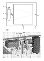
- the elevator installation is, for example, arranged in a largely vertical shaft 10.
- the shaft 10 has, for example, a rectangular cross section with four walls.
- cabin guides 5, 5 'and counterweight guides 9, 9' are attached.
- Two car guides carry a car 11 and two counterweight guides carry a counterweight 12.
- the guides are attached to nearest walls.
- the two counterweight guides 9, 9 'and a first cabin guide 5 are fixed to a first wall.
- the second cabin guide 5 ' is attached to a second wall.
- the second wall is opposite the first wall.
- the first cabin guide 5 is arranged substantially centrally between the two counterweight guides 9, 9 '.
- the guides are made of proven materials such as steel.
- the attachment of the guides on the walls takes place, for example, via screw. With knowledge of the present invention, other shaft geometries with square, oval or round cross-section can be realized.
- the horizontal connecting end between the two counterweight guides forms a first side of the triangle T.
- the horizontal connecting ends between a counterweight guide and a car guide form second and third sides of the triangle T.
- the horizontal connecting end of the counterweight guides is longer than a horizontal connecting end of the car guides that a triangle T consisting of guides 9, 9 ', 5 of the first wall has one of the horizontal connecting ends of the counterweight guides 9, 9' opposite obtuse angle or that a triangle T consisting of the counterweight guides 9, 9 'of the first wall and a Cabin guide 5 'of the second wall has one of the horizontal connecting ends of the counterweight guides 9, 9' opposite acute angle.
- the horizontal connecting end of the car guide cuts the horizontal connecting end of the Counterweight guides largely centered, so that the triangle T is largely isosceles.
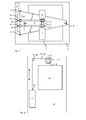
- FIGS. 2 to 10 show an engine 1, 2, 3, 3 ', 4, 40 with two traction sheaves 3, 3'.
- the traction sheaves 3, 3 ' via a shaft 4 with a motor 1 and a brake 2 operatively connected.
- the motor and brake are arranged on two end regions of the shaft and the traction sheaves are arranged between the motor and the brake in a central region of the shaft.
- a controller and / or a converter of the elevator installation is advantageously arranged in a control box 6 on a wall in the shaft 10.
- the prime mover is gearless and of oblong shape, i.
- the diameter of the drive machine is less than the length of the drive machine.
- the drive machine is provided with a gear 40.
- the prime mover is of elongate shape, i. seen in a plane perpendicular to the axis of the transmission 40, the diameter of the prime mover is less than the length of the prime mover.
- two traction sheaves 3, 3 ' symmetrically, left and right of a horizontal connecting ends of the cabin guides 5, 5' are arranged.
- the traction sheaves 3, 3 ' are smaller in diameter than the motor housing and / or the brake housing.
- the largely horizontally arranged in the shaft drive machine moves the at least one propellant 19, 19 'interconnected cabin and counterweight in the shaft.
- the propellant has two ends 18, 18 '.
- the propellant is a rope and / or a belt of any nature.
- the load bearing areas of the propellant are made of metal such as steel and / or plastic such as aramid.
- the rope can be a single or multiple rope, also the rope can be an external plastic protective cover exhibit.
- the belt can be flat and structurally unstructured on the outside or structured, for example, in V-ribs or toothed belts.
- two blowing agents are used.
- two traction sheaves move two propellants via static friction.
- the person skilled in the art can also use other drive machines and drive methods other than those shown in the examples.
- the person skilled in the art can use a drive machine with only one or more than two traction sheaves.
- the person skilled in the art can use a drive pinion, which drive pinion is in positive engagement with a toothed belt as a propellant.
- FIG. 2 shows a perspective view of a part of a first exemplary embodiment of the arrangement of a gearless drive machine 1, 2, 3, 3 ', 4.
- the drive machine is mounted on the traverse 8 arranged largely horizontally in the shaft 10.
- the traverse is, for example, an elongated square made of proven materials such as steel.
- the traverse is attached to the counterweight guides 9, 9 'and to the cab guide 5 of the first wall.
- the traverse is attached to the counterweight guides via two end regions and to a cabin guide over a central region. The attachment of the traverse to these three guides is done in the three attachment areas eg. Via screw.
- the drive machine is mounted indirectly via a bracket 7 on the cross member 8.
- the console is mounted on the central region of the traverse.
- the console is mounted on the crossbeam 8 via feet 7.5, 7.6.
- the console consists, for example, of flat edge or square of proven materials such as steel and is, for example, mounted via screw on the crossbar.
- the prime mover is attached to the console via a motor housing and a brake housing.
- the motor housing is attached to a first console mount 7.1 and the brake housing to a second console mount 7.2.
- the two console holders 7.1, 7.2 are, for example, connected to one another in a rigid manner with respect to the axis of the shaft 4 via struts 7.3, 7.4.
- the console holders 7.1, 7.2 at least partially boundaries of the motor housing and the brake housing.
- the console brackets 7.1, 7.2 end faces of the motor housing and the brake housing.
- motor 1 and brake 2 are arranged in a region substantially outside an envelope of the console 7, while the traction sheaves 3, 3 'are arranged in a region substantially within the envelope of the console 7.
- the traverse 8 is attached at least at the vertices of the triangle T.
- the traverse 8 is located with two end portions on the Counterweight guides 9, 9 'on and with the central region it is on the side of at least one cabin guide 5, 5'.
- the console is mounted on the central region of the traverse.
- the prime mover can thus be freely arranged on the surface of the triangle T either largely above the counterweight and / or largely above the cabin.
- weight forces of the drive machine and bending moments occurring during operation of the drive machine are, for example, effectively absorbed by the bracket and directed into the shaft bottom via the traverse and the guides.
- the guides are, for example, supported by foot plates on the shaft floor.
- the first console mount 7.1 originates from the motor 1, and the second console mount 7.2 absorbs brake forces resulting from the brake 2. Also take the two console brackets 7.1, 7.2 on the traction sheaves 3, 3 'originating forces.
- the two traction sheaves 3, 3 'symmetrical, left and right of the horizontal connecting ends of the car guides 5, 5' are arranged.
Abstract
Description
- Die vorliegende Erfindung bezieht sich auf eine Aufzugsanlage und auf ein Verfahren zur Anordnung einer Antriebsmaschine einer Aufzugsanlage gemäss der Definition der Patentansprüche.
- Eine Aufzugsanlage, bei der eine Antriebsmaschine eine Kabine und ein Gegengewicht über ein Antriebsseil verfährt und welche Aufzugsanlage keinen separaten Maschinenraum benötigt, ist aus dem Gebrauchsmuster JP-50297/1992 bekannt. Als Führung für Kabine und Gegengewicht dienen zwei vertikale Säulen in Form von selbsttragenden U-Profilen. Die Säulen sind an ihrem oberen Ende mit einer horizontalen Traverse abgeschlossen, auf der die Antriebsmaschine montiert ist. Durch das Wegfallen des Maschinenraums weist diese Aufzugsanlage den Vorteil geringerer Gestehungskosten auf.
- Das Patent EP-1045811 zeigt eine Aufzugsanlage, bei der eine die Antriebsmaschine tragende Traverse an insgesamt vier Führungen für Kabine und Gegengewicht befestigt ist. Auf diese Weise wird die gesamte vertikale Gewichtskraft von Antriebsmaschine, Kabine und Gegengewicht ausschliesslich über diese Führungen auf den Schachtboden geleitet und dort abgestützt. Dabei finden preiswerte, konventionelle Führungen Verwendung. Hinzu kommt der weitere Vorteil, dass die Antriebsmaschine keine Biegemomente auf die tragenden Führungen ausübt, da durch diese Anordnung und Befestigung nur vertikale Kräfte auf die Führungen wirken. Nachteilig an dieser Aufzugsanlage ist die Einschränkung der Anordnung der Antriebsmaschine auf den seitlichen Schachtbereich, in dem die Führungen verlaufen.
- Aufgabe der vorliegenden Erfindung ist es, eine Aufzugsanlage mit flexibler Anordnung der Antriebsmaschine bereit zustellen. Die Antriebsmaschine soll weitgehend im gesamten Schachtbereich oberhalb von Kabine und Gegengewicht frei wählbar anzuordnen sein. Die Antriebsmaschine soll platzsparend angeordnet und von kleinen Abmessungen sein.
- Diese Aufgabe wird durch die Erfindung gemäss der Definition der Patentansprüche gelöst.
- Die Erfindung betrifft eine Aufzugsanlage mit Kabine und Gegengewicht und einem Schacht. Sie weist eine auf einer Traverse montierte Antriebsmaschine auf. Die Traverse ist über zwei Endbereiche an je einer Gegengewichtsführung befestigt und sie ist mit einem mittleren Bereich an mindestens einer Kabinenführung befestigt.
- Die zwei Gegengewichtsführungen und eine Kabinenführung spannen im Schacht ein weitgehend horizontales Dreieck auf. Die Antriebsmaschine ist von länglicher und kompakter Form. Vorteilhafterweise weist die Antriebsmaschine zwei Treibscheiben auf, welche symmetrisch, links und rechts von einer horizontalen Verbindenden der Kabinenführungen angeordnet sind.
- Durch diese im Dreieck symmetrische Anordnung der Führungen werden Gewichtskräfte der Antriebsmaschine sowie beim Betrieb der Antriebsmaschine auftretende Biegemomente effektiv aufgenommen und über die Traverse und die Führungen in den Schachtboden geleitet. Die Antriebsmaschine lässt sich auf der Fläche dieses Dreiecks frei wählbar entweder weitgehend oberhalb des Gegengewichts und/oder weitgehend oberhalb der Kabine anordnen. Diese Flexibilität hinsichtlich der Anordnung der Antriebsmaschine wird durch Grösse und Form der Traverse und/oder die Anzahl der verwendeten Umlenkrollen und/oder die Art des verwendeten Treibmittels ermöglicht.
- Im Folgenden wird die Erfindung anhand beispielhafter Ausführungsformen gemäss der Fig. 1 bis 10 im Detail erläutert. Hierbei zeigen:
- Fig. 1
- eine schematische Darstellung der Dreiecks-Anordnung von Führungen einer Aufzugsanlage,
- Fig. 2
- eine perspektivische Ansicht eines Teils eines ersten Ausführungsbeispiels der Anordnung einer getriebelosen Antriebsmaschine in 2:1-Aufhängung und in der vertikalen Projektion oberhalb des Gegengewichts,
- Fig.3
- eine schematische Draufsicht eines Teils des ersten Ausführungsbeispiels der Anordnung der Antriebsmaschine gemäss Fig. 2,
- Fig.4
- eine schematische Ansicht eines Teils des ersten Ausführungsbeispiels der Anordnung der Antriebsmaschine in 2:1-Aufhängung gemäss Fig. 2 und 3,
- Fig. 5
- eine schematische Draufsicht eines Teils eines zweiten Ausführungsbeispiels der Anordnung einer getriebelosen Antriebsmaschine in 2:1-Aufhängung und in der vertikalen Projektion oberhalb von Gegengewicht und/oder Kabine,
- Fig. 6
- eine schematische Ansicht eines Teils des zweiten Ausführungsbeispiels der Anordnung der Antriebsmaschine in 2:1-Aufhängung gemäss Fig. 5,
- Fig. 7
- eine schematische Draufsicht eines Teils eines dritten Ausführungsbeispiels der Anordnung einer getriebelosen Antriebsmaschine in 2:1-Aufhängung und in der vertikalen Projektion oberhalb der Kabine,
- Fig. 8
- eine schematische Ansicht eines Teils eines dritten Ausführungsbeispiels der Anordnung der Antriebsmaschine in 1:1-Aufhängung gemäss Fig. 7,
- Fig. 9
- eine schematische Draufsicht eines Teils eines vierten Ausführungsbeispiels der Anordnung einer Antriebsmaschine mit Getriebe in 2:1-Aufhängung und in der vertikalen Projektion oberhalb der Kabine, und
- Fig. 10
- eine schematische Draufsicht eines Teils eines vierten Ausführungsbeispiels der Anordnung einer Antriebsmaschine mit Getriebe in 2:1-Aufhängung gemäss Fig. 9.
- Fig. 1 zeigt eine schematische Darstellung der Dreiecks-Anordnung von Führungen 5, 5', 9, 9' einer Aufzugsanlage. Die Aufzugsanlage ist bspw. in einem weitgehend vertikalen Schacht 10 angeordnet. Der Schacht 10 weist bspw. einen rechteckigen Querschnitt mit vier Wänden auf. Im Schacht sind weitgehend vertikal angeordnete Kabinenführungen 5, 5' und Gegengewichtsführungen 9, 9' befestigt. Zwei Kabinenführungen führen eine Kabine 11 und zwei Gegengewichtsführungen führen ein Gegengewicht 12. Die Führungen sind an nächstliegenden Wänden befestigt. Die zwei Gegengewichtsführungen 9, 9' und eine erste Kabinenführung 5 sind an einer ersten Wand befestigt. Die zweite Kabinenführung 5' ist an einer zweiten Wand befestigt. Die zweite Wand liegt der ersten Wand gegenüber. Die erste Kabinenführung 5 ist weitgehend mittig zwischen den zwei Gegengewichtsführungen 9, 9' angeordnet. Die Führungen sind aus bewährten Materialien wie Stahl. Die Befestigung der Führungen an den Wänden erfolgt bspw. über Schraubverbindungen. Bei Kenntnis der vorliegenden Erfindung lassen sich auch andere Schachtgeometrien mit quadratischem-, ovalem- bzw. rundem Querschnitt realisieren.
- Die zwei Gegengewichtsführungen 9, 9' und jeweils eine der beiden Kabinenführungen 5, 5' spannen im Schacht 10 ein weitgehend horizontales Dreieck T auf. Die horizontale Verbindende zwischen den beiden Gegengewichtsführungen bildet eine erste Seite des Dreiecks T. Die horizontalen Verbindenden zwischen einer Gegengewichtsführung und einer Kabinenführung bilden zweite- und dritte Seiten des Dreiecks T. Vorteilhafterweise ist die horizontale Verbindende der Gegengewichtsführungen länger als eine horizontale Verbindende der Kabinenführungen, so dass ein Dreieck T bestehend aus Führungen 9, 9', 5 der ersten Wand einen der horizontalen Verbindenden der Gegengewichtsführungen 9, 9' gegenüberliegenden stumpfen Winkel auf weist bzw. dass ein Dreieck T bestehend aus den Gegengewichtsführungen 9, 9' der ersten Wand und einer Kabinenführung 5' der zweiten Wand einen der horizontalen Verbindenden der Gegengewichtsführungen 9, 9' gegenüberliegenden spitzen Winkel aufweist. Vorteilhafterweise schneidet die horizontale Verbindende der Kabinenführungen die horizontale Verbindende der Gegengewichtsführungen weitgehend mittig, so dass das Dreieck T weitgehend gleichschenklig ist.
- Die Fig. 2 bis 10 zeigen eine Antriebsmaschine 1, 2, 3, 3', 4, 40 mit zwei Treibscheiben 3, 3' auf. Vorteilhafterweise sind die Treibscheiben 3, 3' über eine Welle 4 mit einem Motor 1 und einer Bremse 2 wirkverbunden. Vorteilhafterweise sind Motor und Bremse an zwei Endbereichen der Welle angeordnet und die Treibscheiben sind zwischen Motor und Bremse in einem mittleren Bereich der Welle angeordnet. Eine Steuerung und/oder ein Umformer der Aufzugsanlage ist in einem Schaltkasten 6 vorteilhafterweise an einer Wand im Schacht 10 angeordnet. In den Ausführungsformen gemäss Fig. 2 bis 8 ist die Antriebsmaschine getriebelos und von länglicher Form, d.h. in einer Ebene senkrecht zur Achse der Welle 4 gesehen, ist der Durchmesser der Antriebsmaschine geringer als die Länge der Antriebsmaschine. In der Ausführungsform gemäss Fig. 9 und 10 ist die Antriebsmaschine mit einem Getriebe 40 versehen. Auch in dieser Ausführungsformen ist die Antriebsmaschine von länglicher Form, d.h. in einer Ebene senkrecht zur Achse des Getriebes 40 gesehen, ist der Durchmesser der Antriebsmaschine geringer als die Länge der Antriebsmaschine.
- Vorteilhafterweise sind zwei Treibscheiben 3, 3' symmetrisch, links und rechts von einer horizontalen Verbindenden der Kabinenführungen 5, 5' angeordnet. Vorteilhafterweise sind die Treibscheiben 3, 3' im Durchmesser kleiner als das Motorgehäuse und/oder das Bremsgehäuse.
- Die weitgehend horizontal im Schacht angeordnete Antriebsmaschine verfährt die über mindestens ein Treibmittel 19, 19' miteinander verbundene Kabine und Gegengewicht im Schacht. Das Treibmittel weisen zwei Enden 18, 18' auf. Das Treibmittel ist ein Seil und/oder ein Riemen von beliebiger Natur. Die lasttragenden Bereiche des Treibmittels bestehen aus Metall wie Stahl und/oder Kunststoff wie Aramid. Das Seil kann ein Einzel-oder Mehrfachseil sein, auch kann das Seil eine aussenseitige Schutzhülle aus Kunststoff aufweisen. Der Riemen kann flach und aussenseitig unstrukturiert glatt oder bspw. in Keilrippen bzw. Zahnriemen strukturiert sein. Vorteilhafterweise werden zwei Treibmittel verwendet.
- Ein jedes der Enden des Treibmittels ist entweder an einer Schachtwand/Schachtdecke und/oder an einer Kabinenführung und/oder an einer Gegengewichtsführung und/oder an einer Traverse 8 und/oder an der Kabine und/oder am Gegengewicht fixiert. Vorteilhafterweise werden die Enden des Treibmittels über elastische Zwischenelemente zum Dämpfen von Körperschall fixiert. Die Zwischenelemente sind bspw. Federelemente, die die Übertragung von als unangenehm wahrgenommenen Schwingungen vom Treibmittel in die Schachtwand/Schachtdecke und/oder Kabinenführung und/oder Gegengewichtsführung und/oder Traverse und/oder Kabine und/oder Gegengewicht verhindern. Mehrere beispielhafte Ausführungsformen von Fixierungen der Enden des Treibmittels werden unterschieden:
- In der Ausführungsform gemäss Fig. 3 und 4 ist ein erstes Ende 18 des Treibmittels an der Schachtwand/Schachtdecke und/oder an der Kabinenführung 5' befestigt und ein zweites Ende 18' des Treibmittels ist an der Schachtwand/Schachtdecke und/oder an der Traverse 8 und/oder an der Kabinenführung 5 befestigt.
- In den Ausführungsformen gemäss Fig. 5 und 6 sowie 9 und 10 sind ein oder beide Enden 18, 18' des Treibmittels an der Schachtwand/Schachtdecke und/oder an der Kabinenführung und/oder an der Traverse befestigt.
- In der Ausführungsform gemäss Fig. 7 und 8 ist ein erstes Ende 18 des Treibmittels an der Kabine 11 befestigt und ein zweites Ende 18 des Treibmittels ist am Gegengewicht 12 befestigt.
- Gemäss den Ausführungsbeispielen bewegen zwei Treibscheiben zwei Treibmittel über Haftreibung. Bei Kenntnis der vorliegenden Erfindung kann der Fachmann auch andere Antriebsmaschinen sowie andere Antriebsverfahren als in den Beispielen dargestellt verwenden. So kann der Fachmann eine Antriebsmaschine mit nur einer - oder mit mehr als zwei Treibscheibe/n verwenden. Auch kann der Fachmann ein Treibritzel verwenden, welches Treibritzel im formschlüssigen Eingriff mit einem Zahnriemen als Treibmittel ist.
- Mehrere beispielhafte Ausführungsformen von Umhängungen werden unterschieden:
- Im ersten Ausführungsbeispiel gemäss Fig. 2 bis 4, im zweiten Ausführungsbeispiel gemäss Fig. 5 und 6 und im vierten Ausführungsbeispiel gemäss Fig. 9 und 10 sind die Kabine und Gegengewicht 2:1 umgehängt. Bei der 2:1 Umhängung der Kabine 11 sind an der Kabine 11 mehrere Umlenkrollen 13, 13', 14, 14' angebracht. Bei der 2:1 Umhängung des Gegengewichts 12 ist am Gegengewicht 12 mindestens eine Umlenkrolle 17, 17' angebracht. Vorteilhafterweise ist die Antriebsmaschine in einem Bereich weitgehend oberhalb der Wegstrecke des Gegengewichts, d.h. in der vertikalen Projektion oberhalb des Gegengewichts angeordnet. Vorteilhafterweise ist die Antriebsmaschine in einem Bereich weitgehend vollständig oberhalb der Wegstrecke der Kabine angeordnet. Vorteilhafterweise ist die Antriebsmaschine in einem Bereich weitgehend oberhalb der Wegstrecke des Gegengewichts und der Kabine, d.h. in der vertikalen Projektion oberhalb des Gegengewichts und der Kabine angeordnet.
- Im dritten Ausführungsbeispiel gemäss Fig. 7 und 8 sind Kabine und Gegengewicht 1:1 umgehängt. Vorteilhafterweise ist die Antriebsmaschine im dritten Ausführungsbeispiel in einem Bereich weitgehend oberhalb der Wegstrecke der Kabine, d.h. in der vertikalen Projektion oberhalb der Kabine angeordnet. Vorteilhafterweise ist die Antriebsmaschine im dritten Ausführungsbeispiel vollständig oberhalb der Wegstrecke der Kabine angeordnet.
- Fig. 2 zeigt eine perspektivische Ansicht eines Teils eines ersten Ausführungsbeispiels der Anordnung einer getriebelosen Antriebsmaschine 1, 2, 3, 3', 4. Die Antriebsmaschine ist auf der weitgehend horizontal im Schacht 10 angeordneten Traverse 8 montiert. Die Traverse ist bspw. ein länglicher Vierkant aus bewährten Materialien wie Stahl. In diesem ersten Ausführungsbeispiel ist die Traverse an den Gegengewichtsführungen 9, 9' und an der Kabinenführung 5 der ersten Wand befestigt. Vorteilhafterweise ist die Traverse über zwei Endbereiche an den Gegengewichtsführungen und über einen mittleren Bereich an einer Kabinenführung befestigt. Die Befestigung der Traverse an diesen drei Führungen erfolgt in den drei Befestigungsbereichen bspw. über Schraubverbindungen.
- Vorteilhafterweise ist die Antriebsmaschine indirekt über eine Konsole 7 auf der Traverse 8 montiert. Vorteilhafterweise ist die Konsole am mittleren Bereich der Traverse montiert. Bspw. ist die Konsole über Füsse 7.5, 7.6 auf der Traverse 8 montiert. Die Konsole besteht bspw. aus Flachkant bzw. Vierkant aus bewährten Materialien wie Stahl und ist bspw. über Schraubverbindungen auf der Traverse montiert. Vorteilhafterweise ist die Antriebsmaschine über ein Motorgehäuse und ein Bremsgehäuse an der Konsole befestigt. Vorteilhafterweise ist das Motorgehäuse an einer ersten Konsolenhalterung 7.1 und das Bremsgehäuse an einer zweiten Konsolenhalterung 7.2 befestigt. Die beiden Konsolenhalterungen 7.1, 7.2 sind bspw. über Streben 7.3, 7.4 biegesteif bezüglich der Achse der Welle 4 miteinander verbunden. Vorteilhafterweise umfassen die Konsolenhalterungen 7.1, 7.2 zumindest bereichsweise Begrenzungen des Motorgehäuses bzw. des Bremsgehäuses. Bspw. umfassen die Konsolenhalterungen 7.1, 7.2 Stirnflächen des Motorgehäuses bzw. des Bremsgehäuses. Vorteilhafterweise sind Motor 1 und Bremse 2 in einem Bereich weitgehend ausserhalb einer Umhüllenden der Konsole 7 angeordnet, während die Treibscheiben 3, 3' in einem Bereich weitgehend innerhalb der Umhüllenden der Konsole 7 angeordnet sind.
- Die Traverse 8 ist zumindest an den Eckpunkten des Dreiecks T befestigt. Vorteilhafterweise liegt die Traverse 8 mit zwei Endbereichen auf den Gegengewichtsführungen 9, 9' auf und mit dem mittleren Bereich liegt sie seitlich an mindestens einer Kabinenführung 5, 5' an.
- Mehrere beispielhafte Ausführungsformen von Traversenbefestigungen werden unterschieden:
- Im Ausführungsbeispiel gemäss Fig. 2 bis 4 - wo die Antriebsmaschine in einem Bereich weitgehend oberhalb der Wegstrecke des Gegengewichts angeordnet ist - ist die Traverse 8 an den Gegengewichtsführungen 9, 9' und an der Kabinenführung 5 der ersten Wand befestigt, welche den Gegengewichtsführungen 9, 9' sowie der Kabinenführung 5 am nächsten liegt. Die Traverse hat die Form eines Rechtecks.
- Im Ausführungsbeispiel Fig. 5 bis 10 - wo die Antriebsmaschine in einem Bereich weitgehend oberhalb der Wegstrecke von Gegengewicht und/oder Kabine angeordnet ist - ist die Traverse 8 an den Gegengewichtsführungen 9, 9' an der Kabinenführung 5 der ersten Wand und/oder an der Kabinenführung 5' der zweiten Wand befestigt. Die Traverse hat in den Ausführungsbeispielen gemäss Fig. 5 bis 8 eine Dreiecksform mit geraden oder gebogenen Seiten und im Ausführungsbeispiel gemäss Fig. 9 und 10 eine T-Form.
- Die Konsole 7 und die Treibscheiben 3, 3' sind vorteilhafterweise in einem zentralen Bereich des Dreiecks T angeordnet. Vorteilhafterweise ist die Konsole am mittleren Bereich der Traverse montiert. Bspw. sind im ersten Ausführungsbeispiel gemäss Fig. 2 die Füsse 7.5, 7.6 der Konsole 7 beidseitig der Kabinenführung 5, 5' und weitgehend gleich beabstandet von der Kabinenführung 5, 5' an der Traverse 8 montiert. Bspw. sind die Treibscheiben 3, 3' beidseitig der Kabinenführung 5, 5' und weitgehend gleich beabstandet von der Kabinenführung 5,5' auf der Welle 4 angeordnet.
- Die Antriebsmaschine lässt sich somit auf der Fläche des Dreiecks T frei wählbar entweder weitgehend oberhalb des Gegengewichts und/oder weitgehend oberhalb der Kabine anordnen. Durch diese im Dreieck T symmetrische Anordnung der Führungen werden Gewichtskräfte der Antriebsmaschine sowie beim Betrieb der Antriebsmaschine auftretende Biegemomente bspw. von der Konsole effektiv aufgenommen und über die Traverse und die Führungen in den Schachtboden geleitet. Die Führungen sind bspw. über Fussplatten auf dem Schachtboden abgestützt.
- Bspw. nimmt im Ausführungsbeispiel gemäss Fig. 2 die erste Konsolenhalterung 7.1 vom Motor 1 herrührende Antriebskräfte auf und die zweite Konsolenhalterung 7.2 nimmt von der Bremse 2 herrührende Bremskräfte auf. Auch nehmen die beiden Konsolenhalterungen 7.1, 7.2 die von den Treibscheiben 3, 3' herrührende Kräfte auf. Vorteilhafterweise sind die zwei Treibscheiben 3, 3' symmetrisch, links und rechts von der horizontalen Verbindenden der Kabinenführungen 5, 5' angeordnet.
- Auch lassen sich in den Ausführungsbeispielen gemäss Fig. 5 bis 8 - wo im Bereich oberhalb des Gegengewichts und/oder weitgehend oberhalb der Kabine mindestens eine Umlenkrolle 15, 15 `, 16, 16' vorgesehen ist - von dieser Umlenkrolle herrührende Kräfte von der Traverse 8 aufnehmen. Vorteilhafterweise ist diese Umlenkrolle an der Traverse 8 bzw. an der Konsole 7 befestigt. Vorteilhafterweise sind Paare von Umlenkrollen 15, 15', 16, 16' symmetrisch, links und rechts von der horizontalen Verbindenden der Kabinenführungen 5, 5' angeordnet. Durch die Anzahl und Position der Umlenkrollen wird eine Flexibilität bei der Anordnung der Antriebsmaschine auf der Fläche des Dreiecks ermöglicht. Insbesondere lässt sich eine hohe Ausnutzung des Schachtvolumens realisieren, wobei Totvolumen weitgehend vermieden wird. Auch lässt sich die Anordnung der Antriebsmaschine gerade bei Modernisierungen an vorgegebene Schachtverhältnisse flexibel anpassen, welche Flexibilität somit die Verwendung von Standardteilen ermöglicht und kostenträchtige Sonderlösungen vermeidet.
Claims (12)
- Aufzugsanlage
mit einer Kabine (11) welche von Kabinenführungen (5, 5`) geführt ist und einem Gegengewicht (12) welches von Gegengewichtsführungen (9, 9`) geführt ist,
mit einer auf einer Traverse (8) montierten Antriebsmaschine (1, 2, 3, 3', 4), welche die über Treibmittel (19, 19') miteinander verbundenen Kabine (11) und Gegengewicht (12) in einem Schacht (10) verfährt,
dadurch gekennzeichnet,
dass die Antriebsmaschine (1, 2, 3, 3', 4) in einem Bereich weitgehend oberhalb der Wegstrecke des Gegengewichtes angeordnet ist und
dass die Traverse (8) an je einer Gegengewichtsführung (9, 9') und an einer einzigen Kabinenführung (5, 5') befestigt ist. - Aufzugsanlage gemäss Anspruch 1,
dadurch gekennzeichnet,
dass die Traverse (8) über zwei Endbereiche an je einer Gegengewichtsführung (9, 9') und mit einem mittleren Bereich an der Kabinenführung (5, 5') befestigt ist
und / oder
dass die Traverse (8) an den Gegengewichtsführungen (9, 9') und an der Kabinenführung (5) einer ersten Wand befestigt ist, welche erste Wand den Gegengewichtsführungen (9, 9`) sowie der Kabinenführung (5) am nächsten liegt. - Aufzugsanlage gemäss Anspruch 2,
dadurch gekennzeichnet,
dass die Antriebsmaschine über eine Konsole (7) an der Traverse (8) montiert ist und dass die Konsole (7) am mittleren Bereich der Traverse (8) montiert ist. - Aufzugsanlage gemäss einem der Ansprüche 1 bis 3,
dadurch gekennzeichnet,
dass die Treibscheiben zwischen Motor und Bremse auf der Welle angeordnet sind
und/oder
dass die Antriebsmaschine über ein Motorgehäuse und ein Bremsgehäuse an der Konsole befestigt ist
und/oder
dass die Treibscheiben weitgehend in einem Bereich innerhalb einer Umhüllenden der Konsole angeordnet sind. - Aufzugsanlage gemäss einem der Ansprüche 1 bis 4,
dadurch gekennzeichnet,
dass die Kabinenführungen und Gegengewichtsführungen weitgehend vertikal im Schacht angeordnet sind
und/oder
dass die Traverse weitgehend horizontal im Schacht angeordnet ist
und/oder
dass die Antriebsmaschine weitgehend horizontal im Schacht angeordnet ist. - Aufzugsanlage gemäss einem der Ansprüche 1 bis 5,
dadurch gekennzeichnet,
dass jedes Treibmittel zwei Enden aufweist, und
dass ein jedes der Enden der Treibmittel
entweder an einer Schachtwand/Schachtdecke
oder an der Gegengewichtsführung
oder an der Kabinenführung
oder an der Traverse
oder am Gegengewicht
oder an der Kabine
fixiert ist. - Aufzugsanlage gemäss einem der Ansprüche 1 bis 6,
dadurch gekennzeichnet,
dass die Kabine 2:1 aufgehängt ist. - Aufzugsanlage gemäss einem der Ansprüche 1 bis 7,
dadurch gekennzeichnet,
dass die Antriebsmaschine zwei Treibscheiben (3, 3') aufweist und
dass die Treibscheiben (3, 3') symmetrisch, links und rechts von einer horizontalen Verbindenden der Kabinenführungen (5, 5') angeordnet sind oder
dass die Treibscheiben (3, 3') beidseitig der Kabinenführung (5, 5') und weitgehend gleich beabstandet von der Kabinenführung (5, 5') auf der Welle (4) angeordnet sind. - Aufzugsanlage gemäss einem der Ansprüche 1 bis 8,
dadurch gekennzeichnet,
dass die Treibmittel Riemen sind
und / oder dass die Antriebsmaschine getriebelos ist. - Verfahren zur Anordnung einer Antriebsmaschine (1, 2, 3, 3`, 4) in einer Aufzugsanlage,
mit einer Kabine (11) welche von Kabinenführungen (5, 5') geführt ist und einem Gegengewicht (12) welches von Gegengewichtsführungen (9, 9') geführt ist,
mit einer auf einer Traverse (8) montierten Antriebsmaschine (1, 2, 3, 3', 4), welche die über Treibmittel (19, 19') miteinander verbundenen Kabine (11) und
Gegengewicht (12) in einem Schacht (10) verfährt,
dadurch gekennzeichnet,
dass die Antriebsmaschine (1, 2, 3, 3', 4) in einem Bereich weitgehend oberhalb der Wegstrecke des Gegengewichts angeordnet wird und
dass die Traverse (8) an je einer Gegengewichtsführung (9, 9') und an einer einzigen Kabinenführung (5, 5') befestigt wird. - Verfahren gemäss Anspruch 10,
dadurch gekennzeichnet,
dass die Traverse über zwei Endbereiche an je einer Gegengewichtsführung und mit einem mittleren Bereich an der Kabinenführung befestigt wird. - Verfahren gemäss Anspruch 10 oder 11,
dadurch gekennzeichnet,
dass Treibscheiben (3, 3') symmetrisch, links und rechts von einer horizontalen Verbindenden der Kabinenführungen (5, 5') angeordnet werden oder
dass die Treibscheiben (3, 3') beidseitig der Kabinenführung (5, 5') und weitgehend gleich beabstandet von der Kabinenführung (5, 5') auf der Welle (4) angeordnet werden.
Priority Applications (2)
| Application Number | Priority Date | Filing Date | Title |
|---|---|---|---|
| EP05112240.6A EP1640308B1 (de) | 2002-09-05 | 2003-08-28 | Anordnung von Antriebsmaschine einer Aufzuganlage |
| CY20161100846T CY1118298T1 (el) | 2002-09-05 | 2016-08-30 | Τοποθετηση του κινητηριου μηχανισμου μιας εγκαταστασης ανελκυστηρα |
Applications Claiming Priority (3)
| Application Number | Priority Date | Filing Date | Title |
|---|---|---|---|
| EP02405768 | 2002-09-05 | ||
| EP03019433A EP1400477B2 (de) | 2002-09-05 | 2003-08-28 | Anordnung von Antriebsmaschine einer Aufzuganlage |
| EP05112240.6A EP1640308B1 (de) | 2002-09-05 | 2003-08-28 | Anordnung von Antriebsmaschine einer Aufzuganlage |
Related Parent Applications (1)
| Application Number | Title | Priority Date | Filing Date |
|---|---|---|---|
| EP03019433A Division EP1400477B2 (de) | 2002-09-05 | 2003-08-28 | Anordnung von Antriebsmaschine einer Aufzuganlage |
Publications (3)
| Publication Number | Publication Date |
|---|---|
| EP1640308A2 true EP1640308A2 (de) | 2006-03-29 |
| EP1640308A3 EP1640308A3 (de) | 2007-02-21 |
| EP1640308B1 EP1640308B1 (de) | 2016-07-13 |
Family
ID=28686038
Family Applications (3)
| Application Number | Title | Priority Date | Filing Date |
|---|---|---|---|
| EP03019433A Expired - Lifetime EP1400477B2 (de) | 2002-09-05 | 2003-08-28 | Anordnung von Antriebsmaschine einer Aufzuganlage |
| EP05107200.7A Expired - Lifetime EP1591404B9 (de) | 2002-09-05 | 2003-08-28 | Aufzugsanlage und Verfahren zur Anordnung einer Antriebsmaschine einer Aufzugsanlage |
| EP05112240.6A Expired - Lifetime EP1640308B1 (de) | 2002-09-05 | 2003-08-28 | Anordnung von Antriebsmaschine einer Aufzuganlage |
Family Applications Before (2)
| Application Number | Title | Priority Date | Filing Date |
|---|---|---|---|
| EP03019433A Expired - Lifetime EP1400477B2 (de) | 2002-09-05 | 2003-08-28 | Anordnung von Antriebsmaschine einer Aufzuganlage |
| EP05107200.7A Expired - Lifetime EP1591404B9 (de) | 2002-09-05 | 2003-08-28 | Aufzugsanlage und Verfahren zur Anordnung einer Antriebsmaschine einer Aufzugsanlage |
Country Status (27)
| Country | Link |
|---|---|
| US (1) | US20040108170A1 (de) |
| EP (3) | EP1400477B2 (de) |
| JP (2) | JP4629963B2 (de) |
| KR (1) | KR101070206B1 (de) |
| CN (2) | CN1328144C (de) |
| AR (1) | AR041156A1 (de) |
| AT (1) | ATE326421T1 (de) |
| AU (1) | AU2003244558B2 (de) |
| BR (1) | BR0303462B1 (de) |
| CA (1) | CA2439181A1 (de) |
| CY (3) | CY1106143T1 (de) |
| DE (1) | DE50303348D1 (de) |
| DK (3) | DK1400477T4 (de) |
| ES (3) | ES2597379T3 (de) |
| HK (3) | HK1064355A1 (de) |
| HU (2) | HUE031357T2 (de) |
| IL (2) | IL157278A (de) |
| MX (1) | MXPA03007689A (de) |
| NO (1) | NO324849B1 (de) |
| PE (1) | PE20040235A1 (de) |
| PL (1) | PL211302B1 (de) |
| PT (2) | PT1400477E (de) |
| RU (1) | RU2365536C2 (de) |
| SG (1) | SG111145A1 (de) |
| SI (2) | SI1400477T2 (de) |
| TW (1) | TWI306445B (de) |
| ZA (2) | ZA200306198B (de) |
Families Citing this family (40)
| Publication number | Priority date | Publication date | Assignee | Title |
|---|---|---|---|---|
| IL180964A (en) * | 2002-09-05 | 2010-11-30 | Inventio Ag | Drive engine for a lift installation and method of mounting a drive engine |
| JP2004142927A (ja) * | 2002-10-28 | 2004-05-20 | Toshiba Elevator Co Ltd | エレベータ装置 |
| US7377366B2 (en) * | 2002-11-25 | 2008-05-27 | Otis Elevator Company | Sheave assembly for an elevator system |
| US20060266592A1 (en) * | 2003-06-20 | 2006-11-30 | Andes Monzon | Compact bedplate with integrated, accessible dead end hitches |
| EP1510493A1 (de) * | 2003-08-12 | 2005-03-02 | Inventio Ag | Aufzugsanlage mit belastungsabhängigem Tragmittelfixpunkt |
| ES2618326T3 (es) | 2004-01-07 | 2017-06-21 | Inventio Ag | Procedimiento para modernizar un accionamiento en una instalación de ascensor |
| EP1627841B1 (de) * | 2004-06-19 | 2013-08-28 | Inventio AG | Antrieb für eine Aufzugsanlage |
| NZ540311A (en) | 2004-06-19 | 2006-11-30 | Inventio Ag | Drive for a lift installation |
| NZ540310A (en) | 2004-06-19 | 2006-03-31 | Inventio Ag | Drive for a lift installation |
| CN101018731B (zh) * | 2004-07-12 | 2010-06-16 | 因温特奥股份公司 | 电梯和用于电梯的滚轮装置 |
| JP5214098B2 (ja) * | 2004-07-17 | 2013-06-19 | インベンテイオ・アクテイエンゲゼルシヤフト | エレベータ設備におけるケージまたは釣り合いおもりの懸架のための装置、および懸架手段の取り付けおよび保守のための方法 |
| EP1621508A3 (de) * | 2004-07-17 | 2006-08-23 | Inventio Ag | Einrichtung zum Aufhängen einer Kabine in einer Aufzugsanlage |
| DE112005003475B4 (de) * | 2005-02-25 | 2019-04-18 | Otis Elevator Co. | Aufzugfahrkorb mit einer abgewinkelten Unterzugs-Verseilungsanordnung |
| DK1698581T3 (da) * | 2005-03-01 | 2011-11-07 | Ind Montanesas Electricas Mecanicas S L | Maskine, løftesystem og maskinrumløs elevator |
| EP1886957A1 (de) | 2006-08-11 | 2008-02-13 | Inventio Ag | Aufzugriemen für eine Aufzuganlage und Verfahren zur Herstellung eines solchen Aufzugriemens |
| EP1935829A1 (de) * | 2006-12-21 | 2008-06-25 | Inventio Ag | Aufzug mit zwei übereinander liegenden Aufzugskabinen in einem Schacht |
| DE202008001786U1 (de) | 2007-03-12 | 2008-12-24 | Inventio Ag | Aufzugsanlage, Tragmittel für eine Aufzugsanlage und Vorrichtung zur Herstellung eines Tragmittels |
| FI20080640L (fi) | 2008-11-28 | 2010-05-29 | Kone Corp | Hissijärjestelmä |
| JP2010184791A (ja) * | 2009-02-13 | 2010-08-26 | Toshiba Elevator Co Ltd | エレベータ |
| JP5416832B2 (ja) * | 2009-04-28 | 2014-02-12 | オーチス エレベータ カンパニー | 騒音を減少させる構造を有するエレベータ巻上機フレーム |
| US20120085594A1 (en) * | 2010-10-11 | 2012-04-12 | Tim Wright | Drive Arrangement for Machine Roomless Elevator |
| CN103459294B (zh) * | 2011-04-06 | 2016-03-02 | 奥的斯电梯公司 | 包括4:1拉绳布置的电梯系统 |
| EP2639194B1 (de) * | 2012-03-15 | 2015-03-11 | ThyssenKrupp Aufzugswerke GmbH | Treibscheibenaufzug ohne Triebwerksraum |
| FI125124B (fi) * | 2012-05-23 | 2015-06-15 | Kone Corp | Hissijärjestely ja menetelmä |
| CN104768863B (zh) | 2012-11-05 | 2018-01-02 | 奥的斯电梯公司 | 包括结构上独立的电梯曳引机导轨安装座的系统 |
| CN103350942A (zh) * | 2013-07-04 | 2013-10-16 | 上海法西驱动技术有限公司 | 采用扁平聚氨酯复合钢带曳引的分离式永磁无齿轮曳引机 |
| ES2564378T3 (es) * | 2013-08-26 | 2016-03-22 | Kone Corporation | Un ascensor |
| JP5787422B1 (ja) * | 2014-04-11 | 2015-09-30 | 東亜工業株式会社 | ワーク積載装置 |
| EP2985255B1 (de) * | 2014-08-11 | 2021-11-17 | KONE Corporation | Aufzug |
| CN104555660A (zh) * | 2015-01-13 | 2015-04-29 | 江南嘉捷电梯股份有限公司 | 一种无机房电梯的布置结构 |
| US10745246B2 (en) | 2015-04-17 | 2020-08-18 | Otis Elevator Company | Elevator system |
| EP3170782A1 (de) * | 2015-11-23 | 2017-05-24 | Sele S.R.L. | Bewegungsanordnung für aufzüge, hebezeuge und dergleichen |
| KR101651804B1 (ko) * | 2016-03-09 | 2016-08-26 | 김옥수 | 덤웨이터 구조물 |
| CN105692411A (zh) * | 2016-04-07 | 2016-06-22 | 江南嘉捷电梯股份有限公司 | 一种无机房电梯布置结构 |
| CN105692414A (zh) * | 2016-04-07 | 2016-06-22 | 江南嘉捷电梯股份有限公司 | 一种无机房电梯 |
| WO2017182256A1 (de) | 2016-04-22 | 2017-10-26 | Inventio Ag | Aufzugsanlage |
| DE202018103585U1 (de) * | 2018-06-25 | 2019-09-26 | Vestner Aufzüge GmbH | Motorlagerung für einen Aufzugsantriebsmotor |
| CN112299201A (zh) * | 2019-07-31 | 2021-02-02 | 爱默生电梯(上海)有限公司 | 一种充电式四驱电梯 |
| CN112374326A (zh) * | 2020-11-09 | 2021-02-19 | 山东奔速电梯股份有限公司 | 一种家用电梯的导靴 |
| KR102438764B1 (ko) * | 2022-02-18 | 2022-09-01 | 주식회사 동남엘리베이터서비스 | Mrl 엘리베이터 설치구조 |
Citations (5)
| Publication number | Priority date | Publication date | Assignee | Title |
|---|---|---|---|---|
| DE9205254U1 (de) * | 1992-04-15 | 1992-06-17 | C. Haushahn Gmbh & Co, 7000 Stuttgart, De | |
| EP0905081A2 (de) * | 1997-09-26 | 1999-03-31 | Kabushiki Kaisha Toshiba | Einsetzen einer Antriebseinheit in einem Aufzugsschacht |
| WO2001027015A1 (de) * | 1999-10-11 | 2001-04-19 | Inventio Ag | Seilaufzug |
| DE10160925A1 (de) * | 2000-12-12 | 2002-06-13 | Otis Elevator Co | Verfahren und Vorrichtung zum Einstellen des Lenkwinkels für eine Aufzugseilscheibe |
| US20020070080A1 (en) * | 2000-11-29 | 2002-06-13 | Shigeo Nakagaki | Elevator |
Family Cites Families (21)
| Publication number | Priority date | Publication date | Assignee | Title |
|---|---|---|---|---|
| US2848077A (en) * | 1956-01-24 | 1958-08-19 | Otis Elevator Co | Elevator guide rail fastener |
| US3559768A (en) * | 1969-12-22 | 1971-02-02 | Henry P Cox | Emergency elevator evacuation of tall buildings |
| US4664230A (en) * | 1984-03-23 | 1987-05-12 | Olsen Lawrence O | Elevator |
| ES2148420T3 (es) * | 1994-06-09 | 2000-10-16 | Aldo Loiodice | Sistema de elevacion autoportante y disposicion para montar el motor principal. |
| PT846645E (pt) * | 1996-12-03 | 2004-10-29 | Inventio Ag | Ascensor de construcao modular |
| CN1091743C (zh) * | 1997-12-23 | 2002-10-02 | 因温特奥股份公司 | 带有驱动轮的钢索式电梯 |
| BR9908230A (pt) * | 1998-02-26 | 2000-10-31 | Otis Elevador Company | Sistema de elevador com motor de acionamento suspenso |
| US6848543B2 (en) * | 1998-10-30 | 2005-02-01 | Otis Elevator Company | Single wall interface traction elevator |
| FI109468B (fi) * | 1998-11-05 | 2002-08-15 | Kone Corp | Vetopyörähissi |
| US6098758A (en) * | 1998-11-23 | 2000-08-08 | Lucent Technologies Inc. | Tower hoist mechanism confined within a tower interior |
| FI111622B (fi) * | 1999-01-27 | 2003-08-29 | Kone Corp | Vetopyörähissi ja taittopyörän käyttö |
| US6601828B2 (en) * | 2001-01-31 | 2003-08-05 | Otis Elevator Company | Elevator hoist machine and related assembly method |
| JP2000344449A (ja) * | 1999-06-02 | 2000-12-12 | Teijin Seiki Co Ltd | エレベータ用駆動装置 |
| JP4404999B2 (ja) * | 1999-08-16 | 2010-01-27 | 三菱電機株式会社 | エレベータ装置 |
| KR20010094686A (ko) * | 2000-04-01 | 2001-11-01 | 백영문 | 기계실 없는 엘리베이터의 권상기 설치구조 및 그설치방법 |
| JP2002080178A (ja) * | 2000-09-04 | 2002-03-19 | Mitsubishi Electric Corp | エレベータ装置 |
| JP4786121B2 (ja) * | 2000-10-10 | 2011-10-05 | 三菱電機株式会社 | エレベータ装置 |
| AT410784B (de) * | 2000-10-12 | 2003-07-25 | Manfred Grubbauer Aufzuege Ges | Aufzug |
| EP1357076B1 (de) * | 2000-12-11 | 2010-02-10 | Mitsubishi Denki Kabushiki Kaisha | Hebevorrichtung für aufzug |
| DE20021886U1 (de) * | 2000-12-23 | 2001-03-15 | Ziehl Abegg Gmbh & Co Kg | Treibscheibenaufzug mit einer Aufzugskabine in Rucksack-Bauweise |
| JP2002241070A (ja) * | 2001-02-19 | 2002-08-28 | Mitsubishi Electric Corp | エレベーター装置 |
-
2003
- 2003-08-06 IL IL157278A patent/IL157278A/en unknown
- 2003-08-06 IL IL157277A patent/IL157277A/en active IP Right Grant
- 2003-08-08 PE PE2003000795A patent/PE20040235A1/es active IP Right Grant
- 2003-08-11 ZA ZA200306198A patent/ZA200306198B/xx unknown
- 2003-08-11 ZA ZA200306199A patent/ZA200306199B/xx unknown
- 2003-08-20 SG SG200304890A patent/SG111145A1/en unknown
- 2003-08-22 JP JP2003298280A patent/JP4629963B2/ja not_active Expired - Lifetime
- 2003-08-27 MX MXPA03007689A patent/MXPA03007689A/es active IP Right Grant
- 2003-08-28 ES ES05112240.6T patent/ES2597379T3/es not_active Expired - Lifetime
- 2003-08-28 CN CNB031577245A patent/CN1328144C/zh not_active Expired - Lifetime
- 2003-08-28 ES ES03019433T patent/ES2265541T5/es not_active Expired - Lifetime
- 2003-08-28 SI SI200330375T patent/SI1400477T2/sl unknown
- 2003-08-28 HU HUE05112240A patent/HUE031357T2/hu unknown
- 2003-08-28 CN CN2007100044160A patent/CN1990373B/zh not_active Expired - Lifetime
- 2003-08-28 TW TW092123725A patent/TWI306445B/zh not_active IP Right Cessation
- 2003-08-28 DE DE50303348T patent/DE50303348D1/de not_active Expired - Lifetime
- 2003-08-28 EP EP03019433A patent/EP1400477B2/de not_active Expired - Lifetime
- 2003-08-28 PT PT03019433T patent/PT1400477E/pt unknown
- 2003-08-28 HU HUE05107200A patent/HUE027175T2/hu unknown
- 2003-08-28 SI SI200332469T patent/SI1591404T1/sl unknown
- 2003-08-28 DK DK03019433.6T patent/DK1400477T4/da active
- 2003-08-28 AT AT03019433T patent/ATE326421T1/de active
- 2003-08-28 EP EP05107200.7A patent/EP1591404B9/de not_active Expired - Lifetime
- 2003-08-28 DK DK05107200.7T patent/DK1591404T3/en active
- 2003-08-28 DK DK05112240.6T patent/DK1640308T3/da active
- 2003-08-28 ES ES05107200.7T patent/ES2565435T3/es not_active Expired - Lifetime
- 2003-08-28 EP EP05112240.6A patent/EP1640308B1/de not_active Expired - Lifetime
- 2003-08-28 PT PT51122406T patent/PT1640308T/pt unknown
- 2003-09-02 CA CA002439181A patent/CA2439181A1/en not_active Abandoned
- 2003-09-02 PL PL361942A patent/PL211302B1/pl unknown
- 2003-09-04 NO NO20033909A patent/NO324849B1/no not_active IP Right Cessation
- 2003-09-04 AR ARP030103217A patent/AR041156A1/es active IP Right Grant
- 2003-09-04 AU AU2003244558A patent/AU2003244558B2/en not_active Ceased
- 2003-09-04 RU RU2003127027/11A patent/RU2365536C2/ru active
- 2003-09-04 KR KR1020030061777A patent/KR101070206B1/ko active IP Right Grant
- 2003-09-05 US US10/656,665 patent/US20040108170A1/en not_active Abandoned
- 2003-09-05 BR BRPI0303462-3A patent/BR0303462B1/pt active IP Right Grant
-
2004
- 2004-09-21 HK HK04107245A patent/HK1064355A1/xx not_active IP Right Cessation
-
2006
- 2006-04-28 HK HK06105065.3A patent/HK1084932A1/zh not_active IP Right Cessation
- 2006-08-09 CY CY20061101119T patent/CY1106143T1/el unknown
- 2006-09-21 HK HK06110500.6A patent/HK1090014A1/zh not_active IP Right Cessation
-
2010
- 2010-07-15 JP JP2010160224A patent/JP2010228921A/ja not_active Withdrawn
-
2016
- 2016-03-04 CY CY20161100190T patent/CY1117496T1/el unknown
- 2016-08-30 CY CY20161100846T patent/CY1118298T1/el unknown
Patent Citations (5)
| Publication number | Priority date | Publication date | Assignee | Title |
|---|---|---|---|---|
| DE9205254U1 (de) * | 1992-04-15 | 1992-06-17 | C. Haushahn Gmbh & Co, 7000 Stuttgart, De | |
| EP0905081A2 (de) * | 1997-09-26 | 1999-03-31 | Kabushiki Kaisha Toshiba | Einsetzen einer Antriebseinheit in einem Aufzugsschacht |
| WO2001027015A1 (de) * | 1999-10-11 | 2001-04-19 | Inventio Ag | Seilaufzug |
| US20020070080A1 (en) * | 2000-11-29 | 2002-06-13 | Shigeo Nakagaki | Elevator |
| DE10160925A1 (de) * | 2000-12-12 | 2002-06-13 | Otis Elevator Co | Verfahren und Vorrichtung zum Einstellen des Lenkwinkels für eine Aufzugseilscheibe |
Also Published As
Similar Documents
| Publication | Publication Date | Title |
|---|---|---|
| EP1400477B1 (de) | Anordnung von Antriebsmaschine einer Aufzuganlage | |
| EP1621509B1 (de) | Anordnung von einer Antriebsmaschine einer Aufzugsanlage | |
| DE69630081T2 (de) | Antriebsscheibenaufzug | |
| DE69907129T3 (de) | Treibscheibenaufzug | |
| DE69931764T2 (de) | Aufzugssystem mit obenliegendem antriebsmotor | |
| DE3907541C2 (de) | ||
| WO1999033742A1 (de) | Seil-aufzug mit treibscheibe | |
| DE29924747U1 (de) | Aufzugsystem mit Antriebsmotor zwischen Aufzugfahrkorb und Aufzugschacht-Seitenwand | |
| EP0763495A1 (de) | Maschinenrahmen | |
| EP3362395A1 (de) | Fahrkorb für einen aufzug in einem aufzugsschacht | |
| EP1234796A1 (de) | Anordnung für Gewichtsausgleichselemente | |
| DE60217935T2 (de) | Seilscheiben-anordnung für ein aufzugsystem | |
| DE10319731B4 (de) | Aufzug | |
| EP1867597B1 (de) | Aufzug | |
| EP1045811B1 (de) | Seil-aufzug mit treibscheibe | |
| EP1194359B1 (de) | Seilzug-aufzuganlage | |
| EP1437322B1 (de) | Treibscheibenaufzug | |
| EP1197466A2 (de) | Aufzug mit oben im Schacht angeordneten Antrieb | |
| WO2023011771A1 (de) | Maschinenraumloses aufzugssystem | |
| DE19963286A1 (de) | Aufzug | |
| DE19963297B4 (de) | Aufzug | |
| DE19963296A1 (de) | Aufzug |
Legal Events
| Date | Code | Title | Description |
|---|---|---|---|
| PUAI | Public reference made under article 153(3) epc to a published international application that has entered the european phase |
Free format text: ORIGINAL CODE: 0009012 |
|
| AC | Divisional application: reference to earlier application |
Ref document number: 1400477 Country of ref document: EP Kind code of ref document: P |
|
| AK | Designated contracting states |
Kind code of ref document: A2 Designated state(s): AT BE BG CH CY CZ DE DK EE ES FI FR GB GR HU IE IT LI LU MC NL PT RO SE SI SK TR |
|
| AX | Request for extension of the european patent |
Extension state: AL BA HR MK YU |
|
| REG | Reference to a national code |
Ref country code: HK Ref legal event code: DE Ref document number: 1090014 Country of ref document: HK |
|
| PUAL | Search report despatched |
Free format text: ORIGINAL CODE: 0009013 |
|
| AK | Designated contracting states |
Kind code of ref document: A3 Designated state(s): AT BE BG CH CY CZ DE DK EE ES FI FR GB GR HU IE IT LI LU MC NL PT RO SE SI SK TR |
|
| AX | Request for extension of the european patent |
Extension state: AL BA HR MK YU |
|
| 17P | Request for examination filed |
Effective date: 20070809 |
|
| AKX | Designation fees paid |
Designated state(s): AT BE BG CH CY CZ DE DK EE ES FI FR GB GR HU IE IT LI LU MC NL PT RO SE SI SK TR |
|
| 17Q | First examination report despatched |
Effective date: 20071004 |
|
| GRAP | Despatch of communication of intention to grant a patent |
Free format text: ORIGINAL CODE: EPIDOSNIGR1 |
|
| INTG | Intention to grant announced |
Effective date: 20160310 |
|
| GRAS | Grant fee paid |
Free format text: ORIGINAL CODE: EPIDOSNIGR3 |
|
| GRAA | (expected) grant |
Free format text: ORIGINAL CODE: 0009210 |
|
| AC | Divisional application: reference to earlier application |
Ref document number: 1400477 Country of ref document: EP Kind code of ref document: P |
|
| AK | Designated contracting states |
Kind code of ref document: B1 Designated state(s): AT BE BG CH CY CZ DE DK EE ES FI FR GB GR HU IE IT LI LU MC NL PT RO SE SI SK TR |
|
| REG | Reference to a national code |
Ref country code: GB Ref legal event code: FG4D Free format text: NOT ENGLISH |
|
| REG | Reference to a national code |
Ref country code: AT Ref legal event code: REF Ref document number: 812133 Country of ref document: AT Kind code of ref document: T Effective date: 20160715 Ref country code: CH Ref legal event code: EP |
|
| REG | Reference to a national code |
Ref country code: IE Ref legal event code: FG4D Free format text: LANGUAGE OF EP DOCUMENT: GERMAN |
|
| REG | Reference to a national code |
Ref country code: FR Ref legal event code: PLFP Year of fee payment: 14 |
|
| REG | Reference to a national code |
Ref country code: DE Ref legal event code: R096 Ref document number: 50315502 Country of ref document: DE |
|
| REG | Reference to a national code |
Ref country code: DK Ref legal event code: T3 Effective date: 20161004 |
|
| REG | Reference to a national code |
Ref country code: PT Ref legal event code: SC4A Ref document number: 1640308 Country of ref document: PT Date of ref document: 20161018 Kind code of ref document: T Free format text: AVAILABILITY OF NATIONAL TRANSLATION Effective date: 20161003 |
|
| REG | Reference to a national code |
Ref country code: NL Ref legal event code: FP |
|
| REG | Reference to a national code |
Ref country code: SE Ref legal event code: TRGR |
|
| REG | Reference to a national code |
Ref country code: ES Ref legal event code: FG2A Ref document number: 2597379 Country of ref document: ES Kind code of ref document: T3 Effective date: 20170118 |
|
| REG | Reference to a national code |
Ref country code: RO Ref legal event code: EPE |
|
| REG | Reference to a national code |
Ref country code: GR Ref legal event code: EP Ref document number: 20160402064 Country of ref document: GR Effective date: 20161118 Ref country code: SK Ref legal event code: T3 Ref document number: E 22127 Country of ref document: SK |
|
| REG | Reference to a national code |
Ref country code: DE Ref legal event code: R097 Ref document number: 50315502 Country of ref document: DE |
|
| PG25 | Lapsed in a contracting state [announced via postgrant information from national office to epo] |
Ref country code: EE Free format text: LAPSE BECAUSE OF FAILURE TO SUBMIT A TRANSLATION OF THE DESCRIPTION OR TO PAY THE FEE WITHIN THE PRESCRIBED TIME-LIMIT Effective date: 20160713 |
|
| PLBE | No opposition filed within time limit |
Free format text: ORIGINAL CODE: 0009261 |
|
| REG | Reference to a national code |
Ref country code: HK Ref legal event code: GR Ref document number: 1090014 Country of ref document: HK |
|
| STAA | Information on the status of an ep patent application or granted ep patent |
Free format text: STATUS: NO OPPOSITION FILED WITHIN TIME LIMIT |
|
| 26N | No opposition filed |
Effective date: 20170418 |
|
| REG | Reference to a national code |
Ref country code: HU Ref legal event code: AG4A Ref document number: E031357 Country of ref document: HU |
|
| REG | Reference to a national code |
Ref country code: FR Ref legal event code: PLFP Year of fee payment: 15 |
|
| REG | Reference to a national code |
Ref country code: FR Ref legal event code: PLFP Year of fee payment: 16 |
|
| PGFP | Annual fee paid to national office [announced via postgrant information from national office to epo] |
Ref country code: LU Payment date: 20190821 Year of fee payment: 17 Ref country code: NL Payment date: 20190821 Year of fee payment: 17 |
|
| PGFP | Annual fee paid to national office [announced via postgrant information from national office to epo] |
Ref country code: IT Payment date: 20190829 Year of fee payment: 17 Ref country code: CZ Payment date: 20190724 Year of fee payment: 17 Ref country code: SI Payment date: 20190719 Year of fee payment: 17 Ref country code: PT Payment date: 20190719 Year of fee payment: 17 Ref country code: SK Payment date: 20190725 Year of fee payment: 17 Ref country code: SE Payment date: 20190821 Year of fee payment: 17 Ref country code: FI Payment date: 20190822 Year of fee payment: 17 Ref country code: RO Payment date: 20190723 Year of fee payment: 17 Ref country code: MC Payment date: 20190819 Year of fee payment: 17 Ref country code: DK Payment date: 20190821 Year of fee payment: 17 |
|
| PGFP | Annual fee paid to national office [announced via postgrant information from national office to epo] |
Ref country code: BG Payment date: 20190826 Year of fee payment: 17 Ref country code: GR Payment date: 20190822 Year of fee payment: 17 Ref country code: HU Payment date: 20190821 Year of fee payment: 17 Ref country code: BE Payment date: 20190821 Year of fee payment: 17 |
|
| PGFP | Annual fee paid to national office [announced via postgrant information from national office to epo] |
Ref country code: AT Payment date: 20190822 Year of fee payment: 17 |
|
| PGFP | Annual fee paid to national office [announced via postgrant information from national office to epo] |
Ref country code: CY Payment date: 20190826 Year of fee payment: 17 |
|
| REG | Reference to a national code |
Ref country code: FI Ref legal event code: MAE |
|
| REG | Reference to a national code |
Ref country code: DK Ref legal event code: EBP Effective date: 20200831 |
|
| REG | Reference to a national code |
Ref country code: SE Ref legal event code: EUG |
|
| PG25 | Lapsed in a contracting state [announced via postgrant information from national office to epo] |
Ref country code: MC Free format text: LAPSE BECAUSE OF NON-PAYMENT OF DUE FEES Effective date: 20200831 |
|
| REG | Reference to a national code |
Ref country code: NL Ref legal event code: MM Effective date: 20200901 |
|
| REG | Reference to a national code |
Ref country code: AT Ref legal event code: MM01 Ref document number: 812133 Country of ref document: AT Kind code of ref document: T Effective date: 20200828 |
|
| REG | Reference to a national code |
Ref country code: SK Ref legal event code: MM4A Ref document number: E 22127 Country of ref document: SK Effective date: 20200828 |
|
| PG25 | Lapsed in a contracting state [announced via postgrant information from national office to epo] |
Ref country code: GR Free format text: LAPSE BECAUSE OF NON-PAYMENT OF DUE FEES Effective date: 20210304 Ref country code: HU Free format text: LAPSE BECAUSE OF NON-PAYMENT OF DUE FEES Effective date: 20200829 Ref country code: CZ Free format text: LAPSE BECAUSE OF NON-PAYMENT OF DUE FEES Effective date: 20200828 Ref country code: CY Free format text: LAPSE BECAUSE OF NON-PAYMENT OF DUE FEES Effective date: 20200828 Ref country code: FI Free format text: LAPSE BECAUSE OF NON-PAYMENT OF DUE FEES Effective date: 20200828 Ref country code: RO Free format text: LAPSE BECAUSE OF NON-PAYMENT OF DUE FEES Effective date: 20200828 Ref country code: LU Free format text: LAPSE BECAUSE OF NON-PAYMENT OF DUE FEES Effective date: 20200828 Ref country code: PT Free format text: LAPSE BECAUSE OF NON-PAYMENT OF DUE FEES Effective date: 20210330 |
|
| REG | Reference to a national code |
Ref country code: BE Ref legal event code: MM Effective date: 20200831 |
|
| PG25 | Lapsed in a contracting state [announced via postgrant information from national office to epo] |
Ref country code: AT Free format text: LAPSE BECAUSE OF NON-PAYMENT OF DUE FEES Effective date: 20200828 Ref country code: BG Free format text: LAPSE BECAUSE OF NON-PAYMENT OF DUE FEES Effective date: 20210228 Ref country code: SE Free format text: LAPSE BECAUSE OF NON-PAYMENT OF DUE FEES Effective date: 20200829 |
|
| PG25 | Lapsed in a contracting state [announced via postgrant information from national office to epo] |
Ref country code: SK Free format text: LAPSE BECAUSE OF NON-PAYMENT OF DUE FEES Effective date: 20200828 |
|
| PG25 | Lapsed in a contracting state [announced via postgrant information from national office to epo] |
Ref country code: IT Free format text: LAPSE BECAUSE OF NON-PAYMENT OF DUE FEES Effective date: 20200828 |
|
| PG25 | Lapsed in a contracting state [announced via postgrant information from national office to epo] |
Ref country code: DK Free format text: LAPSE BECAUSE OF NON-PAYMENT OF DUE FEES Effective date: 20200831 Ref country code: BE Free format text: LAPSE BECAUSE OF NON-PAYMENT OF DUE FEES Effective date: 20200831 Ref country code: SI Free format text: LAPSE BECAUSE OF NON-PAYMENT OF DUE FEES Effective date: 20200829 |
|
| REG | Reference to a national code |
Ref country code: SI Ref legal event code: KO00 Effective date: 20210812 |
|
| PG25 | Lapsed in a contracting state [announced via postgrant information from national office to epo] |
Ref country code: NL Free format text: LAPSE BECAUSE OF NON-PAYMENT OF DUE FEES Effective date: 20200901 |
|
| PGFP | Annual fee paid to national office [announced via postgrant information from national office to epo] |
Ref country code: FR Payment date: 20210826 Year of fee payment: 19 Ref country code: IE Payment date: 20210819 Year of fee payment: 19 |
|
| PGFP | Annual fee paid to national office [announced via postgrant information from national office to epo] |
Ref country code: GB Payment date: 20210826 Year of fee payment: 19 Ref country code: ES Payment date: 20210910 Year of fee payment: 19 Ref country code: TR Payment date: 20210817 Year of fee payment: 19 Ref country code: CH Payment date: 20210823 Year of fee payment: 19 |
|
| REG | Reference to a national code |
Ref country code: DE Ref legal event code: R084 Ref document number: 50315502 Country of ref document: DE |
|
| PGFP | Annual fee paid to national office [announced via postgrant information from national office to epo] |
Ref country code: DE Payment date: 20220831 Year of fee payment: 20 |
|
| REG | Reference to a national code |
Ref country code: CH Ref legal event code: PL |
|
| GBPC | Gb: european patent ceased through non-payment of renewal fee |
Effective date: 20220828 |
|
| PG25 | Lapsed in a contracting state [announced via postgrant information from national office to epo] |
Ref country code: LI Free format text: LAPSE BECAUSE OF NON-PAYMENT OF DUE FEES Effective date: 20220831 Ref country code: CH Free format text: LAPSE BECAUSE OF NON-PAYMENT OF DUE FEES Effective date: 20220831 |
|
| PG25 | Lapsed in a contracting state [announced via postgrant information from national office to epo] |
Ref country code: IE Free format text: LAPSE BECAUSE OF NON-PAYMENT OF DUE FEES Effective date: 20220828 Ref country code: FR Free format text: LAPSE BECAUSE OF NON-PAYMENT OF DUE FEES Effective date: 20220831 |
|
| REG | Reference to a national code |
Ref country code: DE Ref legal event code: R071 Ref document number: 50315502 Country of ref document: DE |
|
| REG | Reference to a national code |
Ref country code: ES Ref legal event code: FD2A Effective date: 20231002 |
|
| PG25 | Lapsed in a contracting state [announced via postgrant information from national office to epo] |
Ref country code: GB Free format text: LAPSE BECAUSE OF NON-PAYMENT OF DUE FEES Effective date: 20220828 Ref country code: ES Free format text: LAPSE BECAUSE OF NON-PAYMENT OF DUE FEES Effective date: 20220829 |