EP1561641A2 - Appareil, méthode et produit informatique pour générer des sons virtuels - Google Patents
Appareil, méthode et produit informatique pour générer des sons virtuels Download PDFInfo
- Publication number
- EP1561641A2 EP1561641A2 EP05002072A EP05002072A EP1561641A2 EP 1561641 A2 EP1561641 A2 EP 1561641A2 EP 05002072 A EP05002072 A EP 05002072A EP 05002072 A EP05002072 A EP 05002072A EP 1561641 A2 EP1561641 A2 EP 1561641A2
- Authority
- EP
- European Patent Office
- Prior art keywords
- dummy sound
- unit
- vehicle
- dummy
- information
- Prior art date
- Legal status (The legal status is an assumption and is not a legal conclusion. Google has not performed a legal analysis and makes no representation as to the accuracy of the status listed.)
- Withdrawn
Links
Images


Classifications
-
- B—PERFORMING OPERATIONS; TRANSPORTING
- B60—VEHICLES IN GENERAL
- B60Q—ARRANGEMENT OF SIGNALLING OR LIGHTING DEVICES, THE MOUNTING OR SUPPORTING THEREOF OR CIRCUITS THEREFOR, FOR VEHICLES IN GENERAL
- B60Q9/00—Arrangement or adaptation of signal devices not provided for in one of main groups B60Q1/00 - B60Q7/00, e.g. haptic signalling
-
- B—PERFORMING OPERATIONS; TRANSPORTING
- B60—VEHICLES IN GENERAL
- B60Q—ARRANGEMENT OF SIGNALLING OR LIGHTING DEVICES, THE MOUNTING OR SUPPORTING THEREOF OR CIRCUITS THEREFOR, FOR VEHICLES IN GENERAL
- B60Q5/00—Arrangement or adaptation of acoustic signal devices
- B60Q5/005—Arrangement or adaptation of acoustic signal devices automatically actuated
- B60Q5/008—Arrangement or adaptation of acoustic signal devices automatically actuated for signaling silent vehicles, e.g. for warning that a hybrid or electric vehicle is approaching
Definitions
- the present invention relates to technology for generating a dummy sound of an engine of a vehicle.
- a dummy sound generating apparatus for an electric vehicle has been disclosed in JP-A-07-182587.
- This apparatus generates a dummy sound suitable for an electric vehicle, such as a starting sound, a running sound and an acceleration/deceleration sound during running.
- the apparatus also allows adjustment of a dummy sound volume in response to surrounding noises.
- a dummy sound generating apparatus generates a dummy sound of a vehicle.
- the dummy sound generating apparatus includes a dummy sound information storage unit that stores one or more dummy sounds; an outer generating unit that generates one of one or more dummy sounds outside of the vehicle upon reception of a dummy sound generation instruction signal; a generation place information storage unit that stores information on a place where a dummy sound is to be generated; a current position information acquiring unit that acquires information on a current position of the vehicle; and a control unit that outputs the dummy sound generation instruction signal to the outer generating unit based on information on the place stored in the generation place information storage unit and information on the current position acquired by the current position information acquiring unit.
- a vehicle according to another aspect of the present invention includes the above dummy sound generating apparatus according to the present invention.
- a dummy sound generating method is a method for generating dummy sound of a vehicle.
- the dummy sound generating method includes acquiring information on a current position of the vehicle; and generating a dummy sound outside the vehicle based on information, stored in advance, on a place where a dummy sound is to be generated and the information acquired on the current position.
- the computer-readable recording medium stores therein a computer program which causes a computer to execute the above method for generating dummy sound of a vehicle.
- a dummy sound generating apparatus equipped with a vehicle includes a dummy sound information storage unit 101, an outer generating unit 102, a generation place information storage unit 103, a current position information acquiring unit 104, a control unit 105, a generation place information input unit 106, a dummy sound generation notifying unit 107, an instruction demand notifying unit 108, a sound collecting unit 109, an inner generating unit 110, a detecting unit 113, an instruction input unit 115 and a detection information storage unit 116.
- the dummy sound information storage unit 101 stores information of a dummy sound generated by the vehicle.
- the dummy sound is a sound obtained by synthesizing, for example, reproductions of engine sounds or braking sounds of a vehicle.
- the dummy sound information storage unit 101 may store information on a plurality of kinds of dummy sounds.
- the kinds of dummy sounds may be sounds falling in a plurality of bands, for example.
- the outer generating unit 102 generates a dummy sound outside of the vehicle based on dummy sound information stored in the dummy sound information storage unit 101. Specifically, for example, reproductions of engine sounds or braking sounds of a vehicle are synthesized, and the dummy sound thus synthesized is outputted, for example, by a speaker provided outside the vehicle.
- the generation place information storage unit 103 stores information identifying a place where a dummy sound is generated.
- the place where a dummy sound is generated may be a place specified by, for example, the latitude and the longitude (for example, it may be "a XX-chome intersecting point” or "at a back gate of XX Elementary School"), and it may be an ordinary public place (for example, "a school zone” or "an intersecting point”).
- the current position information acquiring unit 104 acquires information on a current position of the vehicle.
- the current position information acquiring unit 104 can be configured to acquire information on the latitude and the longitude by a GPS 410 described later.
- the control unit 105 controls an output of a dummy sound generation instruction signal to the outer generating unit 102 based on information stored in the generation place information storage unit 103 and information acquired by the current position information acquiring unit 104.
- the control unit 105 may be configured to control an output of a dummy sound generation instruction signal to the outer generating unit 102 based on at least one of calendar information and time information.
- the dummy sound generation instruction signal can be, for example, a signal that instructs ON/OFF (start/termination) of a dummy sound generation.
- the control unit 105 may be configured to change a direction in which a dummy sound is generated by the outer generating unit 102 based on information stored in the generation place information storage unit 103 and information acquired by the current position information acquiring unit 104. Specifically, such a configuration may be employed that, for example, when a vehicle moves straight, a dummy sound is generated in a forward direction, and when the steering wheel is steered left or light and the vehicle turns left or right, a dummy sound is generated in the direction that the vehicle turns.
- the control unit 105 is configured to output a dummy sound selecting signal that selects at least one dummy sound from the information on a plurality of kinds of dummy sounds stored in the dummy sound information storage unit 101 based on information stored in the generation place information storage unit 103 and information acquired by the current position information acquiring unit 104.
- the control unit 105 may be configured to control an output of a dummy sound generation instruction signal to the outer generating unit 102 based on information stored in the generation place information storage unit 103 and information acquired by the current position information acquiring unit 104 and to control an output of a sound volume control instruction signal to an audio apparatus 111, such as a CD player, an MD player, a cassette tape player, a DVD player, or a car navigation device, provided inside the vehicle.
- the sound volume control instruction signal may be, for example, an instruction signal that mutes the sound volume of the audio apparatus 111 or reduces the sound volume to a predetermined volume. As a result, it can be made clear to a driver or vehicle passenger that a dummy sound is being generated.
- the generation place information input unit 106 receives an input corresponding to information of a place where a dummy sound is generated.
- the generation place information storage unit 103 stores information corresponding to the input received by the generation place information input unit 106.
- the dummy sound generation notifying unit 107 notifies that a dummy sound is being generated.
- the control unit 105 performs output control of a generation notifying instruction signal to the dummy sound generation notifying unit 107 when a dummy sound generation instruction signal is provided to the outside-vehicle generation unit 102.
- the instruction demand notifying unit 108 issues a notification that a demand for an instruction for a dummy sound has been generated.
- the control unit 105 performs output control of an instruction demand notifying instruction signal to the instruction demand notifying unit 108 based on information stored in the generation place information storage unit 103 and information acquired by the current position information acquiring unit 104 or based on information stored in the detection information storage unit 116 instead of performing output control of a dummy sound generation instruction signal to the outer generating unit 102.
- the sound collecting unit 109 collects outside-vehicle surrounding sounds including a dummy sound generated outside the vehicle by the outer generating unit 102.
- a function of the unit 109 can be implemented by, for example, a microphone provided outside the vehicle.
- the inner generating unit 110 generates dummy sounds collected by the sound collecting unit 109 inside the vehicle.
- the inner generating unit 110 can output, for example, vehicle-outside surrounding sounds collected by a speaker provided outside the vehicle.
- the detecting unit 113 detects various predetermined situations when the vehicle is running.
- the detecting unit 113 can detect a situation outside the vehicle in addition to, for example, a vehicle speed, the rpm of the engine, and a state of the transmission (or gear).
- the situation outside the vehicle includes at least one of a weather condition, a road situation, a situation of a pedestrian and a situation of other vehicles such as a bicycle.
- the detecting unit 113 may be configured to detect a position where the vehicle is running.
- the detecting unit 113 may be configured to detect a state of operation of the vehicle instead of detecting the various predetermined situations while the vehicle is running or in addition to detecting the various predetermined situations while the vehicle is running.
- the state of operation of the vehicle can be, for example, a state of the steering wheel, the acceleration pedal, the braking pedal, the transmission, the lighting switches for the lights, or a wiper.
- the detecting unit 113 is configured to detect a state of a driver of the vehicle.
- the state of a driver of the vehicle can be, for example, a fatigue degree or a continuous driving time of the driver.
- the control unit 105 controls an output of a dummy sound generation instruction signal to the outer generating unit 102 based on information stored in the generation place information storage unit 103 and information acquired by the current position information acquiring unit 104 or based on the result detected by the detecting unit 113.
- the control unit 105 may be configured to change a direction in which a dummy sound is generated by the outer generating unit 102 based on information stored in the generation place information storage unit 103 and information acquired by the current position information acquiring unit 104 or based on the result detected by the detecting unit 113.
- the control unit 105 may be configured to output a dummy sound selecting signal that selects at least one dummy sound from information on a plurality of kinds of dummy sounds stored in the dummy sound information storage unit 101 based on information stored in the generation place information storage unit 103 and information acquired by the current position information acquiring unit 104 or based on the result detected by the detecting unit 113.
- the control unit 105 may be configured to control an output of a sound volume control instruction signal to the audio apparatus 111 provided inside the vehicle and to control an output of a dummy sound generation instruction signal to the outer generating unit 102 based on information stored in the generation place information storage unit 103 and information acquired by the current position information acquiring unit 104 or based on the result detected by the detecting unit 113.
- the instruction input unit 115 receives an instruction to start/terminate a dummy sound generation provided inside the vehicle. Specifically, the instruction input unit 115 receives an instruction to start/terminate a dummy sound generation by turning ON/OFF a dummy sound generating switch provided, for example, inside the vehicle.
- the detection information storage unit 116 stores information on the result detected by the detecting unit 113 when a start/terminate instruction of a dummy sound generation is issued by the instruction input unit 115.
- the control unit 105 controls an output of the dummy sound generation instruction signal to the outer generating unit 102 based on the start/terminate instruction of a dummy sound generation issued by the instruction input unit 115 and controls an output of the dummy sound generation instruction signal to the outer generating unit 102 on the basis of information stored in the detection information storage unit 116 and the result detected by the detecting unit 113.
- the control unit 105 can compare, for example, one or a combination of two or more of a weather situation, a road situation, a situation of walkers and a situation of other vehicles (e.g., a bicycle), a state of operation of a vehicle, and a state of a drive of the vehicle, which are stored in the detection information storage unit 116.
- This information can be obtained by the control unit 105 when a start instruction for a dummy sound generation has been issued, with one or a combination of a weather situation, a road situation, a situation of walkers and a situation of other vehicles including a bicycle, a state of operation of a vehicle, a state of the driver of the vehicle, which are detected by the detecting unit 113.
- the control unit 105 also outputs a dummy sound instruction signal when the former information and the latter information are coincident with each other. A termination instruction to a dummy sound generation is made similarly.
- the control unit 105 performs various controls in this manner, but such a configuration may be implemented so that these controls are respectively performed alone or performed with any combination thereof.
- Fig. 2 is a flowchart of one example of a process performed by a dummy sound generating method according to the embodiment of the invention. First, a determination is made about whether the vehicle starts to run (step S201).
- step S201 if standby is maintained until the vehicle starts to run and the processing starts after the vehicle starts to run (step S201: yes), then a determination is made about whether an instruction to start a dummy sound generation has been issued by turning ON a dummy sound generation switch provided inside the vehicle (step S202). If the dummy sound generating switch is not turned ON (step S202: No), then the control moves to step S208 without performing any processing.
- step S202 when the dummy sound generating switch is turned ON (step S202: Yes), information relating to a place (position) at that moment (generation place information), a situation or status obtained at this time is stored (step S203). It is determined whether a dummy sound is already being generated (step S204). If the dummy sound is already being generated (step S204: Yes), then the control moves to step S208 without performing any processing.
- step S204 determines whether the audio apparatus is in operation (step S205).
- step S205 determines whether the audio apparatus is in operation (step S205).
- the control moves to step S207 without performing any processing.
- step S206 the volume of the audio apparatus is adjusted (step S206), and a dummy sound is generated (step S207).
- the driver or vehicle passenger may be notified that the dummy sound is being generated.
- step S208 it is determined whether an instruction for termination of the dummy sound generation has been issued by turning OFF the dummy sound generating switch provided inside the vehicle. If the dummy sound generating switch is turned OFF (step S208: Yes), information relating to a place (position) at that moment (generation place information), a situation or status obtained at this time is detected, information on the detection situation is stored (step S209), and the control moves to step S212.
- step S208 if the dummy sound generating switch is not turned OFF (step S208: No), it is determined whether a present position is a place where a dummy sound is generated or whether a predetermined situation is detected (step S210). If the present position is not the place where the dummy sound is generated or if the predetermined situation is not detected (step S210: No.), the control moves to step S216. On the contrary, if the present position is the place where the dummy sound is generated or if the predetermined situation is detected (step S21 0: Yes), then it is determined whether the detected situation is related to a start instruction or whether it is related to a termination instruction (step S211).
- step S211 if the situation is the start instruction (step S211: start), then the control returns back to step S204, but the control moves to step S212 if the situation is the termination instruction (step S211: termination).
- step S212 it is determined whether the dummy sound is being generated.
- the control moves to step S216 without performing any processing. Meanwhile, if the dummy sound is being generated (step S212: Yes), then the dummy sound is stopped (step S213). If notification is being made when the dummy sound is being generated, the notification is stopped.
- step S214 It is determined whether the audio apparatus is operating (step S214). Here, if the audio apparatus is not operating (step S214: No), then the control moves to step S216 without performing any processing. Meanwhile, if the audio apparatus is operating (step S214: Yes), then the sound volume of the audio apparatus is adjusted (step S215). For example, the sound volume can be returned back to a sound volume before the dummy sound is generated, and the control moves to step S216.
- step S216 it is determined if the vehicle has stopped running (step S216). If the vehicle running has not yet stopped running (step S216: No), then the control returns back to step S202, and steps S202 to S216 are performed repeatedly. If the vehicle stops running (step S216: Yes), a series of processings is terminated.
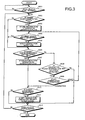
- Fig. 3 is a flowchart of another example of a process for a dummy sound generating method according to the embodiment of the present invention.
- the flowchart shown in Fig. 3 is for notifying a dummy sound instruction demand to an operator or a vehicle passenger instead of actual generation of a dummy sound.
- it is determined whether a vehicle has started to run (step S301).
- step S301 if standby is maintained until the vehicle starts to run and processing starts after the vehicle starts to run (step S301: Yes), then a determination is made about whether an instruction for starting dummy sound generation has been issued by turning ON the dummy sound generating switch provided inside the vehicle (step S302). If the dummy sound generating switch is not turned ON (step S302: No), then the control moves to step S306 without performing any processing.
- step S302 if the dummy sound generating switch is turned ON (step S302: Yes), then information relating to a place (position) at that moment (generation place information), a situation or status detected at that time is stored (step S303). It is determined whether a dummy sound is already being generated (step S304). If the dummy sound is already being generated (step S304: Yes), then the control moves to step S306 without performing any processing. If a dummy sound is not being generated, however (step S304: No), then a generation instruction for a dummy sound is demanded by notifying a driver or vehicle passenger to turn ON a dummy sound generation switch (step S305).
- step S306 it is determined whether an instruction for termination of the dummy sound generation has been issued by turning OFF the dummy sound generating switch provided inside the vehicle. If the dummy sound generating switch is turned OFF (step S306: Yes), then information relating to a place (position) at that moment (generation place information), the situation or status at that time is detected, information on the detected situation is stored (S307), and the control moves to step S310.
- step S310 it is determined whether the dummy sound is being generated. If the dummy sound is not being generated (step S310: No), then the control moves to step S312 without performing any processing. Meanwhile, if the dummy sound is being generated (step S310: Yes), then the dummy sound is stopped (step S311), and the control moves to step S312.
- step S306 if the dummy sound generating switch is not turned OFF (step S306: No), then it is determined whether a present position is a place where a dummy sound is generated or whether a predetermined situation has been detected (step S308). If the present position is not the place where the dummy sound is generated or if the predetermined situation has not been detected (step S308: No), the control moves to step S312. On the contrary, if the present position is the place where the dummy sound is generated or if the predetermined situation has been detected (step S308: Yes), then it is determined whether the detected situation is related to a start instruction or to a termination instruction (step S309).
- step S309 if the situation is the start instruction (step S309: start), then the control returns back to step S304. The control moves to step S310 if the situation is the termination instruction (step S309: termination).
- step S310 it is determined whether the dummy sound is being generated. If the dummy sound is not being generated (step S310: No), then the control moves to step S312 without performing any processing. If the dummy sound is being generated (step S310: Yes), then a stop instruction of the dummy sound is demanded by notifying the driver or vehicle passenger to turn OFF the dummy sound generating switch (step S311). The dummy sound may be stopped without demanding the stop instruction. Thereafter, the control moves to step S312.
- step S312 it is determined whether the vehicle has stopped running. When the vehicle has not yet stopped running (step S312: No), the control returns back to step S302, and steps S302 to S312 are performed repeatedly. If the vehicle has stopped running (step S312: Yes), a series of processings is terminated.
- a dummy sound such as a dummy running sound, i.e., an engine sound.
- a pedestrian recognizes that a vehicle is approaching from behind by hearing but not seeing the approaching vehicle. If the pedestrian feels danger, the pedestrian may turn to see the approaching vehicle in some cases. Accordingly, when a vehicle approaches without being heard by the pedestrian, the pedestrian may not recognize that the vehicle is approaching, which may be problematic to the pedestrian.
- a pedestrian when an alarm sound is generated by a horn or by an artificial alarm sound when a vehicle moves back, a pedestrian may be surprised by the sound and feel uncomfortable or stressed in many cases. Accordingly, it is useful for a pedestrian to recognize the approach or passing-through of a vehicle. That is, since there is a problem if the pedestrian does not notice or recognize the approach of a vehicle, it is useful to notify the pedestrian of the approach of a vehicle. Accordingly, a sound to be generated is preferably a normally generated dummy sound, and by generating a dummy sound at an applicable time, the safety of a pedestrian can be achieved while limiting noise generation.
- Fig. 4 is a block diagram of a dummy sound generating apparatus according to the example of the present invention.
- sign 401 denotes a CPU that controls a whole dummy sound generating apparatus
- 402 denotes a ROM in which a basic processing program for the dummy sound generating apparatus has been stored
- 403 denotes a RAM that is used as a work area of the CPU 401.
- Sign 404 denotes a hard disc drive (HDD) that controls reading/writing of data to a hard disk (HD) 405 according to control of the CPU 401
- 405 denotes the HD that stores data written according to the control of the HDD 404.
- an attachable/detachable recording medium such as a CD, a DVD (not shown) may be provided.
- Sign 406 denotes an interface (I/F), and the I/F 406 is connected to various devices 411 to 418 described later via radio or cables and it functions as an interface between the various devices and the CPU 401.
- Sign 400 denotes a bus for connection of various units. The members 400 to 406 realize a function of the control unit 105 shown in Fig. 1.
- the GPS 410 denotes a GPS (Global Positioning Systems).
- the GPS 410 is a system that receives signals from a GPS satellite to obtain a geometrical position with respect to the GPS satellite, and it allows measurement to be made anywhere on the earth.
- the signal is a carrier wave with 1.575.42 MHz, and measurement is performed using L1 wave carrying C/A (Coarse and Access) code and a navigation message.
- Sign 411 denotes a variety switches including the dummy sound generation instruction switch, and it provides a function of the instruction input unit 115 shown in Fig. 1.
- the switches include buttons on a touch panel on a display 414 described below.
- Sign 412 denotes a microphone that collects surrounding sounds outside the vehicle, and it provides a function of the sound collecting unit 109 shown in Fig. 1.
- Sign 413 denotes an audio apparatus provided with a CD drive, an MD drive, a DVD drive or similar device, and it provides a function of the audio apparatus 111 shown in Fig. 1.
- Sign 414 denotes a display such as a liquid crystal display or an organic EL display
- 415 denotes various lamps such as LEDs.
- the display 414 and the various lamps 415 realize functions of the dummy sound generation notifying unit 107 and the instruction demand notifying unit 108.
- the lamps 415 can notify predetermined messages to a driver or vehicle passenger according to the emitted colors (for example, an orange LED), timing of blinking, or the like.
- Sign 416 denotes a speaker switching device that performs switching among directions of an output of an outer speaker 419 described later
- 417 denotes an amplifier that controls an output of the outer speaker 419
- 418 denotes an amplifier that controls an output of an inner speaker 420.
- the amplifier 417 outputs (generates) a synthesized dummy sound by the outer speaker 419 based on a control signal transmitted via the I/F 406.
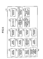
- Fig. 5 is an explanatory diagram of the detecting unit 113 of the dummy sound generating apparatus according to the example of the present invention.
- the detecting unit 113 is provided as a device for detecting a state of a vehicle with a speed sensor 501, an acceleration pedal sensor 502 and a braking pedal sensor 503, a steering wheel steering angle sensor 504, a gear sensor 505, a wiper sensor 506, a direction indicator sensor 507, a horn (klaxon) sensor 508, an infrared sensor 511 a millimeter wave radar 512, a Doppler radar 513, an infrared camera 514 and the like.
- the millimeter wave radar 512 and the infrared camera 514 are used to confirm a situation outside the vehicle.
- the speed sensor 501 detects a speed of the vehicle, for example, besides the GPS 410.
- the acceleration pedal sensor 502 detects a stepping-in degree of the acceleration pedal, an opening degree of a throttle or the like.
- the braking pedal sensor 503 detects a stepping-in degree of the braking pedal.
- the steering wheel steering angle sensor 504 detects a steering angle or a steering speed (about whether the steering wheel is steered fast or slow) when the steering wheel is steered left or right.
- the gear operation sensor 505 detects a state of a gear shifted or automatically switched.
- the wiper sensor 506 detects presence/absence of actuation of a wiper, a wiper actuation speed or the like.
- the direction indicator sensor 507 detects presence/absence of actuation of the direction indicator (the winker), which direction is indicated, and an operation time.
- the horn sensor 508 detects whether the horn (klaxon) has been actuated, an operation time, a state where the horn button (generally, a predetermined position on the steering wheel) has not been pushed down but a hand of the driver is in contact with the horn button, or the like.
- the infrared sensor 511 detects whether a moving subject is an animal.
- the millimeter wave radar 512 detects a distance to a subject and a speed of the subject.
- the millimeter wave radar 512 is a device that detects an obstacle using a wave such as a radar used in an airplane. A collision is predicted in advance by searching for an obstacle ahead of the vehicle using the millimeter wave radar 512 and monitoring the data by a computer on the vehicle. Further, the millimeter wave radar 512 can predict a collision from urgent braking conducted by the driver.
- the infrared sensor 511 can search for a situation in a surrounding area of about 100 meters, can be used in fog, rain, or snow, and may be implemented as a radar system using a wave with a 76GHz band having an antenna power of approximately 10 millimeter watts.
- the millimeter wave radar 512 is configured for placement on a front face of a vehicle as part of an inter-automobile control device (ACC) system that detects an inter-vehicle distance to a vehicle running ahead or a relative speed thereto to support safe driving.
- ACC inter-automobile control device
- the millimeter wave radar 512 may also be part of an ITS (Intelligent Traffic System).
- the Doppler radar 513 detects a relative speed between the vehicle and a subject.
- the driver can confirm whether the subject is moving in the same direction as the vehicle or is moving in an opposite direction.
- the infrared camera 514 detects a pedestrian at night who may be overlooked with head lamps or street lamps to alarm the driver. Infrared detects a heat source of a human or animal even during the night.
- a bio sensor 521, a vehicle compartment camera 522, and a continuous running time clock 523 may be provided for detecting conditions of the driver.
- the bio sensor 521 detects, for example, the heart rate of the driver.
- the vehicle compartment camera 522 detects the driver and the driver's eye ball movement and behavior.
- the continuous running time clock 523 clocks a continuous run time to estimate a degree of fatigue of the driver based on the clocked time.
- a raindrop sensor 531, a temperature/humidity sensor 532, a wind force/wind direction sensor 533 are provided for detecting situations outside the vehicle.
- the raindrop sensor 531 detects presence/absence of raindrops and an amount thereof. Since a pedestrian may not notice the approach of a vehicle due to falling rain, it may be useful to generate a dummy sound is generated even at a place where a dummy sound would not otherwise be generated in good weather.
- the temperature/humidity sensor 532 detects the temperature and the humidity outside the vehicle.
- the wind force/wind direction sensor 533 detects a wind force and a wind direction outside the vehicle. Since a pedestrian may not notice the approaching of a vehicle due to the sound of wind on a strong windy day, it may be useful to generate a dummy sound even at a place where a dummy sound would not otherwise be generated.
- the HD 405 realizes functions of the dummy sound information storage unit 101 and the detection information storage unit 106 shown in Fig. 1.
- the HD 405 stores a musical instrument digital interface (MIDI) sound source, which reproduces dummy sounds such as a plurality of kinds of engine sounds or braking sounds and a sequence software, which is a software for performing reproduction of MIDI data.
- MIDI musical instrument digital interface
- the kinds of engine sounds or braking sounds include ones with different bands. It is preferable to take into consideration the size of the vehicle for the generated dummy sound so that a pedestrian can intuitively comprehend the size of the vehicle from the sound.
- an ordinary motorcar, a truck, and a bus can generate different dummy sounds.
- the dummy sound may be generated as a sound easily heard by a person with relatively disabled hearing, such as an aged person.
- the HD 405 stores map data used for display of the GPS 410. Specifically, the HD 405 stores information on roads or buildings corresponding to the position information (latitude/longitude) that the GPS 410 has acquired or stored in advance.
- the HD 405 stores information detected by the detecting unit 113 as the detection information storage unit 116 shown in Fig. 1.
- Fig. 6 is an explanatory diagram of one example of information stored in the HD 405 functioning as the detection information storage unit 116.
- information detected for each predetermined time interval includes day and time item 601, position item 602, direction item 603, object item 604, vehicle speed item 605, and temperature/humidity item 606.
- Information stored in the day and time item 601 is used, for example, for determining whether a certain place is a dangerous zone depending on a time zone. In particular, a determination is made that a place is a dangerous zone when it corresponds to an attending school time and is not a dangerous zone when it corresponds to any other time.
- Numerical values regarding the latitude (north or south) and the longitude (east or west) detected/calculated by the GPS 410 are stored in the position item 602.
- Information on a moving direction of a vehicle is stored in the direction item 603. The moving direction of the vehicle can be calculated from the latitude and longitude detected just before the current time and the latitude and longitude detected at the current time.
- Information on an object (a pedestrian, a bicycle or the like) moving in the same direction as a moving direction of a vehicle and an object moving in a direction opposite to the moving direction of the vehicle is stored in the object item 604.
- Display of the same direction: 0, the opposite direction: 3 in the item shows such a fact that there is not any object moving in a separating direction and there are three objects moving in an approaching direction.
- the direction detection of a pedestrian or a bicycle may be made, for example, by analyzing a face image of the pedestrian to determine whether the pedestrian is walking away from the vehicle or toward the vehicle. It is possible to acquire a relative speed between a pedestrian and the vehicle with the millimeter wave radar 512 and to determine that the pedestrian is opposed to the vehicle when the relative speed is large and that the pedestrian walks in the same direction as the vehicle when the relative speed is small.
- Information on a vehicle speed acquired from the speed sensor 501 is stored in the vehicle speed item 605.
- Information on a temperature and a humidity acquired from, for example, the temperature/humidity sensor 532 is stored in the temperature/humidity item 606.
- the control unit 105 shown in Fig. 1 controls an output of the dummy sound generation instruction signal or the instruction demand notifying instruction signal based upon these information pieces.
- a dummy sound may be generated depending on the sound volume of the stored noises around the vehicle.
- the sound volume of the dummy sound may be adjusted depending on the volume of the noises around the vehicle.
- the HD 405 stores therein information on a determination table for controlling an output of a dummy sound generation instruction signal to the outer generating unit 102 shown in Fig. 1.
- Fig. 7 is explanatory diagrams of one example of a determination table stored in the HD 405 functioning as the detection information storage unit 106.
- Fig. 7 is a diagram of one example of a table predicting places requiring a dummy sound (dangerous zones) from map data.
- a vehicle crosses a sidewalk from a principal road to enter in an establishment such as a gas station or a convenience store, the crossing place is determined as a dangerous zone based upon the latitude/longitude information and the map data, so that the dummy sound generation instruction switch is turned ON.
- the vehicle deviates from a principal road, such as to enter a parking area for a shop or when the vehicle is located near a service area of an express highway, such a position is determined as a dangerous zone.
- a sound may be just for just a short time. It is also possible that a sound is only generated at a certain crossing or when a sidewalk is crossed. In such a case, only these spots may be stored.
- the conditions for turning OFF the dummy sound generation instruction switch include a situation such as when the vehicle has entered an express highway.
- Fig. 8 to Fig. 11 are explanatory diagrams of one example of a determination table stored in the HD 405 functioning as the detection information storage unit 116.
- Fig. 8 is a diagram of one example of a table that predicts a dangerous zone based upon vehicle data (e.g., a speed, a steering angle of the steering wheel, and a braking operation). In the table shown in Fig.
- Fig. 9 is a diagram of one example of a table that predicts dangerous zones from physiological data.
- the heart rate of the driver when the heart rate of the driver is high, when eyeball movement occurs frequently and the driver exercises precaution, or when the driver makes frequent body movement and is restless, it is determined based upon information pieces from the bio sensor 521 and the vehicle compartment camera 522 that the place where the vehicle is running (current time point) is a dangerous zone, and the dummy sound generation instruction switch is turned ON.
- Fig. 10 is a diagram of one example of a table that determines a dangerous zone from an image.
- a person when a person is present in a running direction of a vehicle, when it is raining, or when the driver cannot recognize a pedestrian footpath due to no road shoulder, it is determined based upon information pieces from the millimeter wave radar 512, the infrared camera 514, the raindrop sensor 531, and the infrared sensor 511 that the place where the vehicle is running (current time point) is a dangerous zone, and the dummy sound generation instruction switch is turned ON.
- Fig. 11 is a diagram of one example of a table that predicts a dangerous zone from route data using the GPS 410.
- the vehicle approaches a target destination, when the vehicle enters in a shopping street, when the vehicle runs on a narrow road or a life road (i.e., a road used in everyday life) except for a principal road, when the vehicle turns at an intersection based upon a determination from a set route, when the vehicle moves from a narrow road to a wide road, when the vehicle enters a narrow road from a principal road, or when the vehicle runs on a road that does not have a footpath, it is determined based upon the latitude/longitude information pieces and the map data that the place where the vehicle is running is a dangerous zone, and the dummy sound generation instruction switch is turned ON.
- Fig. 12 to Fig. 15 are flowcharts of one example of a procedure of a determination processing performed in the control unit 105.
- the flowchart shown in Fig. 12 shows content of a determination processing based on a state of a driver.
- it is determined whether the vehicle is in a preset dangerous zone at the current time (step S1201). If the vehicle is in the dangerous zone, (step S1201: Yes), then control is performed to generate a dummy sound regardless of the detection result obtained by the various sensors (step S1204), and the control returns back to step S1201.
- step S1201 If the vehicle is out of the dangerous zone (step S1201: No), it is determined whether a vehicle speed is slow and the steering wheel is frequently steered (step S1202), and it is determined whether the driver is tense (step S1203). If either one of the processings is satisfied (step S1202: Yes or step S1203: Yes), then control is made to generate a dummy sound (step S1204), and the control returns back to step S1201.
- step S1202 If none of the processings is satisfied (step S1202: No and step S1203: No), then control is performed to stop the dummy sound (step S1205), and the control returns back to step S1201.
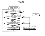
- the flowchart shown in Fig. 13 shows content of a determination processing based upon a situation outside the vehicle.
- it is determined whether the dummy sound generation instruction switch is ON (step S1301). If the switch is ON (step S1301: Yes), it is determined whether a pedestrian is present ahead of the vehicle (step S1302) and whether the pedestrian notices the presence of the vehicle (step S1303). If no pedestrian is present (step S1302:No) or if the pedestrian is present (step S1302: Yes) but notices the presence of the vehicle (step S1303: Yes), then control is made to stop a dummy sound (step S1305), and the control returns back to step S1301.
- step S1303 if the walker does not notice the presence of the vehicle (step S1303: No), then control is made to generate a dummy sound (step S1304), and the control returns back to step S1301.
- step S1301 if the switch is OFF (step S1301: No), then the processing terminates. With such a process, it is possible to prevent the useless, continuous generation of a dummy sound.
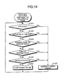
- the flowchart shown in Fig. 14 shows content of a determination processing to find from the map data whether it is a dangerous zone. As shown in Fig. 14, it is determined whether the current point is on a life road (step S1401), whether actuation was made in the past (step S1402), whether the current point is in a parking zone or an SA (a service area) (step S1403), whether the vehicle is turning at an intersection (step S1404) and whether the vehicle crosses a predestrian footpath (step S1405).
- step S1401 Yes, step S1402: Yes, step S1403: Yes, step S1404: yes or step S1405: Yes
- step S1407 If the vehicle falls under any one of the above situations (step S1401: Yes, step S1402: Yes, step S1403: Yes, step S1404: yes or step S1405: Yes), then it is determined that the vehicle is present in a dangerous zone, control is made to generate a dummy sound (step S1407), and control returns back to step S1401.
- step S1401 No, step S1402: No, step S1403: No, step S1404: No and step S1405: No
- step S1406 control is made to stop a dummy sound
- step S1405 control returns back to step S1401.
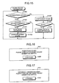
- Fig. 15 shows content of a processing that controls a sound volume of the audio apparatus 413 interlocked with the control of dummy sound generation.
- a predestrian is present ahead of a vehicle (step S1501). If a pedestrian is present (step S1501: Yes), it is determined whether the audio apparatus 413 is making a sound (step S1502). If the audio apparatus 413 is making the sound, (step S1502: Yes), then the audio is muted or the volume is lowered (step S1503). If the audio apparatus is not making a sound (step S1502: No), then nothing is done. Regardless of whether the audio apparatus 413 is making a sound, a dummy sound is generated (step S1504), and the control returns back to step S1501.
- step S1501 if a walker is not present ahead (step S1501: No), then control is made to stop the dummy sound (step S1505). Thereafter, it is determined whether the audio apparatus 413 is muted or whether the volume is lowered (step S1506). If the audio apparatus 413 has been muted (or volume lowered) (step S1506: Yes), the muted state is cancelled (step S1507). None is done, however, if the audio apparatus 413 has not been muted (step S1506: No). Thereafter, the control returns back to step S1501. With such a process, a driver can easily recognize that a dummy sound has been generated automatically.
- a dummy sound may be generated by touching a horn button. If an indication of the approach or passing-through of a vehicle cannot be established by generation of a dummy sound, the indication can be provided to a pedestrian by pushing down the horn button. As a result, a pedestrian can be notified of the approach or passing-through of a vehicle without causing unnecessary discomfort or stress to the pedestrian.
- FIG. 16 to Fig. 19 are explanatory diagrams of one example of content notified by the instruction demand notifying unit 108.
- a display screen 1601 shown in Fig. 16 makes notification to turn ON a dummy sound generation switch when a pedestrian is present.
- a display screen 1701 shown in Fig. 17 makes notification to turn ON the dummy sound generation switch when a vehicle has entered into a dangerous zone.
- a display screen 1801 shown in Fig. 18 makes notification to turn OFF the dummy sound generating switch when the vehicle has left the dangerous zone.
- a display screen 1901 shown in Fig. 19 makes notification to turn OFF the dummy sound generating switch when a dummy sound is being continuously generated for a certain time or the vehicle has traveled a predetermined distance while continuously generating a dummy sound. In either case, the display screens 1601, 1701, 1801, and 1901 are cancelled by pushing down "confirmation" buttons 1602, 1702, 1802, and 1902.
- the instruction demand notification can be made using a display 414, but it is possible for the instruction demand notification to be made in other ways. For example, notification can be made in accordance with the light-emitting color of a lamp, the timing of the blinking of the lamp, or a voice notification.
- FIG. 20 is an explanatory diagram of one example of content notified by the dummy sound generation notifying unit 107.
- a display screen 2001 shown in Fig. 20 is for confirming to the driver, if the dummy sound generating switch is operated, whether a place where the switch is operated should be registered as a dangerous zone. Registration is made by pushing "Yes" button 2002. The place is not registered as a dangerous zone by pushing "No" button 2003.
- the dummy sound generation notification has been made using a display 414, but it is possible for the dummy sound generation notification to be made in other ways. For example, notification can be made in accordance with the light-emitting color of a lamp, the timing of the blinking of the lamp, or a voice notification.
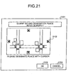
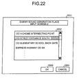
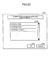
- FIG. 21 to Fig. 23 are explanatory diagrams of one example of an input screen of generation place information provided by the generation place information input unit 106.
- a map image 2102 such as a display image of a car navigation, is displayed. Further, a place where a dummy sound is to be generated is designated on the displayed map image 2102 by a cursor, and an "OK" button 2103 is pushed down so that latitude/longitude information on the designated place is extracted and stored in the generation place information storage unit 103 as dummy sound generation place information.
- a dummy sound generation place input screen 2201 shown in Fig. 22 specific places including latitude/longitude information, such as "XX 4-chome intersecting point" or "XX street entrance south," are displayed on a selection field 2202 as a list. Further, a desired place is selected from the list, and an "OK" button 2203 is pushed down so that the latitude/longitude information of the place is stored in the generation place information storage unit 103 as dummy sound generation place information.
- a dummy sound generation place input screen 2301 shown in Fig. 23 public places that do not include latitude/longitude information, such as "school zones" or “intersecting points," are displayed on a selection field 2302 as a list. Further, a desired place is selected from the list, and an "OK" button 2303 is pushed down so that latitude/longitude information on all corresponding places is extracted and stored in the generation place information storage unit 103 as a dummy sound generation place information.
- buttons 2104, 2204 and 2304 when "cancel" buttons 2104, 2204 and 2304 are pushed down, all processing is suspended, and the input screens 2101, 2201 and 2301 are deleted.
- the outer generating unit 102 since the dummy sound information storage unit 101 stores information on a dummy sound, the outer generating unit 102 generates a dummy sound outside the vehicle based on information stored in the dummy sound information storage unit 101, the generation place information storage unit 103 stores information on a place in which a dummy sound is to be generated, the current place information acquiring unit 104 acquires information on the current position of a vehicle, and the control unit 105 controls an output of a dummy sound generation instruction signal to the outer generating unit 102 based on information stored in the generation place information storage unit 103 and information acquired by the current position information acquiring unit 104, a dummy sound (a dummy running sound) of the vehicle can be generated when the vehicle runs at a predetermined place.
- the approach or passing-through of a vehicle can be notified to a pedestrian near the vehicle, and attention can be provided to the pedestrian. Accordingly, noises are reduced, a drawback due resulting from such reduced noises is removed, and safe passage of a pedestrian can be ensured.
- the generation place information input unit 106 receives input of information on a place where a dummy sound is to be generated, and the generation place information storage unit 103 stores information whose input has been received by the generation place information input unit 106, the driver can generate a dummy sound at a desired place.
- the control unit 105 controls an output of a dummy sound generation instruction signal to the outer generating unit 102, notification about the approaching or passing-through of a vehicle can be made based on a predetermined situation when the vehicle is running, and attention can be provided.
- the detection information storage unit 116 stores information on the result detected by the detecting unit 113 when an instruction to start/terminate a dummy sound generation is issued by the instruction input unit 115, and the control unit 105 controls an output of a dummy sound generation instruction signal to the outer generating unit 102 based on information stored in the detection information storage unit 116 and the result detected by the detecting unit 113, it is possible to store information regarding where a dummy sound was generated in the past, and a dummy sound can be generated automatically when the vehicle is in the same situation.
- the detecting unit 113 may be configured to detect a situation outside the vehicle.
- the situation outside the vehicle may include, for example, at least one of a weather situation, a road situation, a situation of a pedestrian and a situation of other vehicles including a bicycle.
- the detecting unit 113 may be configured to detect a position where the vehicle is running.
- the detecting unit 113 may be configured to detect a condition of the driver of a vehicle.
- the detecting unit 113 may be configured to detect a state of operation of the vehicle.
- the control unit 105 may be configured to change a direction in which a dummy sound is generated by the outer generating unit 102 based upon the state of operation of the vehicle detected by the detecting unit 113. With such a configuration, a dummy sound can be generated more properly.
- the control unit 105 may be configured to control an output of a dummy sound generation instruction signal to the outer generating unit 102 based upon at least one of calendar information and time information. More specifically, for example, such a configuration can be employed that a dummy sound is generated due to a weekday or a holiday, or morning or night, even at the same place.
- the dummy sound information storage unit 101 stores information on various kinds of dummy sounds (specifically, for example, an MIDI sound source), and the control unit 105 outputs a dummy sound selecting signal that selects at least one of the kinds of dummy sounds.
- the control unit 105 may be configured to control an output of a dummy sound generation instruction signal to the outer generating unit 102 based upon the result detected by the detected unit 113 and to control an output of a sound volume control instruction signal to the audio apparatus 111 (413) provided inside the vehicle. Thereby, even when a dummy sound is automatically generated, it is possible to notify the driver of the automatically generated dummy sound.
- the control unit 104 controls an output of a dummy sound generation notifying instruction signal to the dummy sound generation notifying unit 107 when a dummy sound generation notifying signal is outputted to the outer generating unit 102, such a fact can be notified to the driver even when a dummy sound has been generated automatically.
- the instruction demand notifying unit 108 makes a notification demanding an instruction to generate a dummy sound
- the control unit 104 controls an output of an instruction demand notifying instruction signal to the outer generating unit 102 instead of controlling an output of a dummy sound generation instruction signal to the instruction demand notifying unit 108, such a configuration can be employed that a dummy sound is prevented from being generated against a driver's intention.
- the sound collecting unit 109 collects surrounding sounds outside a vehicle including dummy sounds generated outside the vehicle by the outer generating unit 102, and the inner generating unit 110 generates the dummy sounds collected by the sound collecting unit 109 inside the vehicle, a dummy sound outputted outside the vehicle and noises outside the vehicle can be recognized reliably even in a state that windows have been closed.
- the dummy sound generating method may be a computer (for example, a micro-computer) readable program prepared in advance and is realized by executing the program in a computer such as a personal computer or a workstation including a server.
- the program is recorded in a computer-readable recording medium such as recorded in a HD, FD, CD-ROM, MO, or DVD and it is executed by reading this program out of the recording medium.
- the program may be a transmission medium that can be distributed via a network such as the Internet.
Landscapes
- Engineering & Computer Science (AREA)
- Mechanical Engineering (AREA)
- Physics & Mathematics (AREA)
- Acoustics & Sound (AREA)
- Human Computer Interaction (AREA)
- Fittings On The Vehicle Exterior For Carrying Loads, And Devices For Holding Or Mounting Articles (AREA)
- Traffic Control Systems (AREA)
Applications Claiming Priority (2)
| Application Number | Priority Date | Filing Date | Title |
|---|---|---|---|
| JP2004032377 | 2004-02-09 | ||
| JP2004032377A JP4316397B2 (ja) | 2004-02-09 | 2004-02-09 | 擬似音発生装置、車両、擬似音発生方法および擬似音発生プログラム |
Publications (2)
| Publication Number | Publication Date |
|---|---|
| EP1561641A2 true EP1561641A2 (fr) | 2005-08-10 |
| EP1561641A3 EP1561641A3 (fr) | 2008-07-02 |
Family
ID=34675595
Family Applications (1)
| Application Number | Title | Priority Date | Filing Date |
|---|---|---|---|
| EP05002072A Withdrawn EP1561641A3 (fr) | 2004-02-09 | 2005-02-02 | Appareil, méthode et produit informatique pour générer des sons virtuels |
Country Status (3)
| Country | Link |
|---|---|
| US (1) | US7650001B2 (fr) |
| EP (1) | EP1561641A3 (fr) |
| JP (1) | JP4316397B2 (fr) |
Cited By (7)
| Publication number | Priority date | Publication date | Assignee | Title |
|---|---|---|---|---|
| WO2010102776A1 (fr) * | 2009-03-11 | 2010-09-16 | Gm Global Technology Operations, Inc. | Véhicule à moteur silencieux doté d'un dispositif de signalisation |
| CN101844540A (zh) * | 2009-03-26 | 2010-09-29 | 雅马哈株式会社 | 装备有扬声器单元的汽车 |
| ITPD20100009A1 (it) * | 2010-01-22 | 2011-07-23 | Mirco Sanguin | Attrezzatura di segnalazione acustica particolarmente per veicoli silenziosi come del tipo dei veicoli con motore elettrico, ed il suo metodo di funzionamento |
| EP2377724A1 (fr) * | 2010-04-15 | 2011-10-19 | Deere & Company | Génération de sons en fonction du contexte |
| CN102700459A (zh) * | 2012-06-25 | 2012-10-03 | 汉得利(常州)电子有限公司 | 新能源汽车用多功能警示系统 |
| FR2983439A1 (fr) * | 2011-12-02 | 2013-06-07 | Renault Sa | Systeme de generation sonore de vehicule automobile pour l'avertissement des individus situes a proximite |
| WO2014031621A3 (fr) * | 2012-08-21 | 2014-04-24 | Harman International Industries, Incorporated | Système pour permettre une synthèse des sons de véhicule |
Families Citing this family (58)
| Publication number | Priority date | Publication date | Assignee | Title |
|---|---|---|---|---|
| JP2005219715A (ja) * | 2004-02-09 | 2005-08-18 | Pioneer Electronic Corp | 擬似音発生装置、車両、擬似音発生方法および擬似音発生プログラム |
| US7787633B2 (en) * | 2005-01-20 | 2010-08-31 | Analog Devices, Inc. | Crossfade sample playback engine with digital signal processing for vehicle engine sound simulator |
| EP2062243A4 (fr) * | 2006-08-21 | 2015-07-01 | Schacht Michael R | Systèmes et procédés pour simuler un mouvement avec un son |
| DE102007003201A1 (de) * | 2006-11-28 | 2008-05-29 | Alfred Trzmiel | Einrichtung zur Erzeugung von Audiosignalen |
| JP4849245B2 (ja) * | 2006-12-18 | 2012-01-11 | マツダ株式会社 | 車両の制御装置 |
| US20090066499A1 (en) * | 2007-07-17 | 2009-03-12 | Enhanced Vehicle Acoustics, Inc. | External sound generating system and method |
| US7812740B2 (en) * | 2007-09-27 | 2010-10-12 | Verizon Patent And Licensing Inc. | Systems, devices, and methods for providing alert tones |
| KR101173944B1 (ko) * | 2008-12-01 | 2012-08-20 | 한국전자통신연구원 | 차량 운전자의 감성 조절 시스템 및 방법 |
| US8138897B2 (en) * | 2009-03-06 | 2012-03-20 | General Motors Llc | Method of generating vehicle noise |
| JP2010208439A (ja) * | 2009-03-09 | 2010-09-24 | Denso It Laboratory Inc | 警報発生装置およびこれを備える自動車 |
| JP4620795B1 (ja) * | 2009-08-07 | 2011-01-26 | 治幸 岩田 | 自動車接近警報システム |
| JP5440087B2 (ja) * | 2009-10-13 | 2014-03-12 | ヤマハ株式会社 | エンジン音生成装置 |
| JP2011084224A (ja) * | 2009-10-18 | 2011-04-28 | Masahide Tanaka | モータ駆動可能な車両 |
| JP5333265B2 (ja) * | 2010-01-28 | 2013-11-06 | 株式会社Jvcケンウッド | 報知音制御装置および報知音制御方法 |
| JP5333264B2 (ja) * | 2010-01-28 | 2013-11-06 | 株式会社Jvcケンウッド | 報知音制御装置および報知音制御方法 |
| WO2011092833A1 (fr) * | 2010-01-29 | 2011-08-04 | パイオニア株式会社 | Dispositif et procédé de génération de bruit pseudo-aléatoire |
| US8730027B2 (en) * | 2010-02-09 | 2014-05-20 | Nissan Motor Co., Ltd. | Vehicle notification sound emitting apparatus |
| JP5644479B2 (ja) * | 2010-02-09 | 2014-12-24 | 日産自動車株式会社 | 車両の警報音発生装置 |
| JP2011162084A (ja) * | 2010-02-10 | 2011-08-25 | Mitsubishi Electric Corp | 車両制御装置及びハイブリッド車両 |
| US8537030B2 (en) * | 2010-02-15 | 2013-09-17 | Ford Global Technologies, Llc | Pedestrian alert system and method |
| WO2011104755A1 (fr) | 2010-02-25 | 2011-09-01 | 三菱電機株式会社 | Dispositif de notification d'approche de véhicule |
| JP5445853B2 (ja) * | 2010-03-03 | 2014-03-19 | カシオ計算機株式会社 | 接近通報装置およびプログラム |
| US8320581B2 (en) * | 2010-03-03 | 2012-11-27 | Bose Corporation | Vehicle engine sound enhancement |
| JP2011193631A (ja) * | 2010-03-15 | 2011-09-29 | Mitsubishi Fuso Truck & Bus Corp | モータ駆動車両の報知装置 |
| CN104960465B (zh) * | 2010-03-25 | 2017-11-28 | 日本先锋公司 | 模拟声产生装置以及模拟声产生方法 |
| US20130016851A1 (en) * | 2010-03-25 | 2013-01-17 | Pioneer Corporation | Pseudonoise generation device and pseudonoise generation method |
| JP2012081962A (ja) * | 2010-03-25 | 2012-04-26 | Pioneer Electronic Corp | 車両想起音出力制御端末装置、サーバ装置及び車両想起音出力制御方法 |
| CN102361777B (zh) | 2010-05-26 | 2014-06-18 | 三菱电机株式会社 | 向车外的声音产生装置 |
| JP4790876B1 (ja) * | 2010-06-08 | 2011-10-12 | パイオニア株式会社 | 車両想起音発生装置及び車両想起音発生方法 |
| WO2012023170A1 (fr) * | 2010-08-16 | 2012-02-23 | 三菱電機株式会社 | Dispositif de commande de son d'alerte de corps mobile électrique |
| CN102404430A (zh) * | 2010-09-13 | 2012-04-04 | 富泰华工业(深圳)有限公司 | 移动通讯装置及其提高通话质量的方法 |
| JP5641223B2 (ja) * | 2010-12-10 | 2014-12-17 | 三菱自動車工業株式会社 | 車両接近通報装置 |
| US9299337B2 (en) | 2011-01-11 | 2016-03-29 | Bose Corporation | Vehicle engine sound enhancement |
| US8892333B2 (en) * | 2011-03-09 | 2014-11-18 | Denso Corporation | Vehicle rank distinction device for vehicle and travel sound generator device |
| US8542844B2 (en) | 2011-04-07 | 2013-09-24 | Visteon Global Technologies, Inc. | Sound modification system and method |
| JP2013014286A (ja) * | 2011-07-06 | 2013-01-24 | Casio Computer Co Ltd | 車両接近通報装置およびプログラム |
| JP5758737B2 (ja) * | 2011-08-10 | 2015-08-05 | 株式会社小糸製作所 | 車両用ランプ |
| WO2013121464A1 (fr) * | 2012-02-16 | 2013-08-22 | 三菱電機株式会社 | Appareil d'émission sonore |
| JP5772721B2 (ja) * | 2012-05-24 | 2015-09-02 | アンデン株式会社 | 車両接近通報装置 |
| DE102012107814A1 (de) * | 2012-08-24 | 2014-05-15 | Dr. Ing. H.C. F. Porsche Aktiengesellschaft | Verfahren und Vorrichtung zur Geräuscherzeugung im Innen- und Außenraum eines Kraftfahrzeugs |
| US20140172234A1 (en) * | 2012-12-13 | 2014-06-19 | Continental Automotive Systems, Inc. | Gps data for improving pedestrian protection |
| JP5731074B2 (ja) * | 2012-12-27 | 2015-06-10 | パイオニア株式会社 | 音出力部制御装置及び音出力部制御方法 |
| JP6111955B2 (ja) * | 2013-09-27 | 2017-04-12 | アンデン株式会社 | 車両接近通報装置 |
| WO2015074140A1 (fr) | 2013-11-21 | 2015-05-28 | Vladimir Savchenko | Procédé et appareil pour mesurer des caractéristiques de mouvement pour bicyclettes et de quelconques véhicules sur roues |
| KR101558362B1 (ko) * | 2013-12-18 | 2015-10-07 | 현대자동차 주식회사 | 차량의 사운드 경고 시스템 및 그것의 제어방법 |
| KR20150142298A (ko) * | 2014-06-11 | 2015-12-22 | 현대자동차주식회사 | 차량, 차량의 제어 방법 및 차량 주행음 제어 장치 |
| US9661402B2 (en) | 2014-07-15 | 2017-05-23 | The Nielsen Company (Us), Llc | Embedding information in generated acoustic signals |
| JP2014223919A (ja) * | 2014-09-11 | 2014-12-04 | パイオニア株式会社 | 擬似音発生装置、擬似音発生方法及び音出力装置 |
| KR101646119B1 (ko) * | 2014-11-27 | 2016-08-05 | 현대자동차 주식회사 | 차량의 vess 유닛 고장 제공 방법 및 그 제공 장치 |
| DE102014226187A1 (de) * | 2014-12-17 | 2016-06-23 | Bayerische Motoren Werke Aktiengesellschaft | Kommunikation mittels eines Luftstoßes |
| JP6217933B2 (ja) * | 2014-12-27 | 2017-10-25 | Nl技研株式会社 | モータ駆動可能な車両 |
| DE102015111054A1 (de) * | 2015-07-08 | 2017-01-12 | Dr. Ing. H.C. F. Porsche Aktiengesellschaft | Geräuschübertragungssystem für ein Kraftfahrzeug und Verfahren für ein Geräuschübertragungssystem |
| DE102016002449A1 (de) * | 2016-02-27 | 2017-08-31 | Audi Ag | Kraftfahrzeug mit einer Steuervorrichtung für zumindest einen Lautsprecher einer Abgasanlage des Kraftfahrzeugs |
| US20170297486A1 (en) * | 2016-04-16 | 2017-10-19 | Rene Magana | Noise simulator |
| JP6785420B2 (ja) * | 2017-05-01 | 2020-11-18 | Nl技研株式会社 | モータ駆動可能な車両 |
| KR102051542B1 (ko) * | 2019-10-07 | 2020-01-08 | (주) 아이티아이일렉트로닉스 | 엑셀레이터의 압력에 따라 가변적으로 발생되는 자동차의 가상 엔진음 생성장치 및 방법 |
| KR102227110B1 (ko) * | 2019-11-29 | 2021-03-12 | (주) 아이티아이일렉트로닉스 | 엑셀레이터 변화량과 미디 및 웨이브를 이용한 자동차 가상 엔진음 생성장치 |
| US11858418B2 (en) * | 2020-12-10 | 2024-01-02 | CRAFTS & MEISTER CO., Ltd | System for generating pseudo driving sound |
Citations (4)
| Publication number | Priority date | Publication date | Assignee | Title |
|---|---|---|---|---|
| JPH07322403A (ja) * | 1994-05-18 | 1995-12-08 | Yamaha Motor Co Ltd | 電気車両の警報音装置 |
| US5635903A (en) * | 1993-12-21 | 1997-06-03 | Honda Giken Kogyo Kabushiki Kaisha | Simulated sound generator for electric vehicles |
| JP2002233001A (ja) * | 2001-01-31 | 2002-08-16 | Fujitsu Ten Ltd | 擬似エンジン音制御装置 |
| JP2002238101A (ja) * | 2001-02-08 | 2002-08-23 | Denso Corp | 電動自動車の警告発生装置 |
Family Cites Families (11)
| Publication number | Priority date | Publication date | Assignee | Title |
|---|---|---|---|---|
| US5237617A (en) * | 1991-10-17 | 1993-08-17 | Walter Miller | Sound effects generating system for automobiles |
| JP2571332Y2 (ja) | 1993-03-09 | 1998-05-18 | 住友電装株式会社 | 電気自動車用ダミー音発生装置 |
| JPH07142946A (ja) | 1993-11-16 | 1995-06-02 | Sumitomo Electric Ind Ltd | 車載用音響機器の音量制御回路 |
| JPH07232571A (ja) | 1994-02-24 | 1995-09-05 | Matsushita Electric Ind Co Ltd | 居眠り運転防止装置 |
| US5586187A (en) * | 1994-07-01 | 1996-12-17 | Webb; James D. | Automotive sound replicator |
| JPH10201001A (ja) | 1997-01-07 | 1998-07-31 | Toshiro Morita | 電気自動車 |
| JPH11288291A (ja) | 1998-04-02 | 1999-10-19 | Sony Corp | 電気自動車 |
| US6275590B1 (en) * | 1998-09-17 | 2001-08-14 | Robert S. Prus | Engine noise simulating novelty device |
| DE19945259C1 (de) * | 1999-09-21 | 2001-01-11 | Bayerische Motoren Werke Ag | Vorrichtung zur elektroakustischen Geräuscherzeugung bei einem Kraftfahrzeug |
| JP3722107B2 (ja) | 2002-10-30 | 2005-11-30 | 株式会社デンソー | ハイブリッド型車両 |
| JP2005219715A (ja) | 2004-02-09 | 2005-08-18 | Pioneer Electronic Corp | 擬似音発生装置、車両、擬似音発生方法および擬似音発生プログラム |
-
2004
- 2004-02-09 JP JP2004032377A patent/JP4316397B2/ja not_active Expired - Fee Related
-
2005
- 2005-02-02 EP EP05002072A patent/EP1561641A3/fr not_active Withdrawn
- 2005-02-07 US US11/050,777 patent/US7650001B2/en not_active Expired - Fee Related
Patent Citations (4)
| Publication number | Priority date | Publication date | Assignee | Title |
|---|---|---|---|---|
| US5635903A (en) * | 1993-12-21 | 1997-06-03 | Honda Giken Kogyo Kabushiki Kaisha | Simulated sound generator for electric vehicles |
| JPH07322403A (ja) * | 1994-05-18 | 1995-12-08 | Yamaha Motor Co Ltd | 電気車両の警報音装置 |
| JP2002233001A (ja) * | 2001-01-31 | 2002-08-16 | Fujitsu Ten Ltd | 擬似エンジン音制御装置 |
| JP2002238101A (ja) * | 2001-02-08 | 2002-08-23 | Denso Corp | 電動自動車の警告発生装置 |
Cited By (8)
| Publication number | Priority date | Publication date | Assignee | Title |
|---|---|---|---|---|
| WO2010102776A1 (fr) * | 2009-03-11 | 2010-09-16 | Gm Global Technology Operations, Inc. | Véhicule à moteur silencieux doté d'un dispositif de signalisation |
| CN101844540A (zh) * | 2009-03-26 | 2010-09-29 | 雅马哈株式会社 | 装备有扬声器单元的汽车 |
| EP2233373A1 (fr) | 2009-03-26 | 2010-09-29 | Yamaha Corporation | Automobile équipée d'une unité de haut-parleur |
| ITPD20100009A1 (it) * | 2010-01-22 | 2011-07-23 | Mirco Sanguin | Attrezzatura di segnalazione acustica particolarmente per veicoli silenziosi come del tipo dei veicoli con motore elettrico, ed il suo metodo di funzionamento |
| EP2377724A1 (fr) * | 2010-04-15 | 2011-10-19 | Deere & Company | Génération de sons en fonction du contexte |
| FR2983439A1 (fr) * | 2011-12-02 | 2013-06-07 | Renault Sa | Systeme de generation sonore de vehicule automobile pour l'avertissement des individus situes a proximite |
| CN102700459A (zh) * | 2012-06-25 | 2012-10-03 | 汉得利(常州)电子有限公司 | 新能源汽车用多功能警示系统 |
| WO2014031621A3 (fr) * | 2012-08-21 | 2014-04-24 | Harman International Industries, Incorporated | Système pour permettre une synthèse des sons de véhicule |
Also Published As
| Publication number | Publication date |
|---|---|
| JP2005219716A (ja) | 2005-08-18 |
| EP1561641A3 (fr) | 2008-07-02 |
| US20050232432A1 (en) | 2005-10-20 |
| US7650001B2 (en) | 2010-01-19 |
| JP4316397B2 (ja) | 2009-08-19 |
Similar Documents
| Publication | Publication Date | Title |
|---|---|---|
| US7650001B2 (en) | Dummy sound generating apparatus and dummy sound generating method and computer product | |
| EP1562177A2 (fr) | Dispositif et procédé de génération de sons fictifs et produit informatique correspondant | |
| CN106364430B (zh) | 车辆控制装置及其车辆控制方法 | |
| EP3425469B1 (fr) | Système d'entraînement pour véhicule et véhicule associé | |
| KR101989102B1 (ko) | 차량용 운전 보조 장치 및 그 제어 방법 | |
| WO2018147041A1 (fr) | Dispositif d'aide au déplacement, dispositif et procédé de gestion d'aide au déplacement, et système d'aide au déplacement | |
| KR20190001145A (ko) | 차량용 인터페이스 시스템 | |
| KR20190033975A (ko) | 차량의 운행 시스템을 제어하는 방법 | |
| JP2007122536A (ja) | 車両用障害物通知装置 | |
| WO2020100585A1 (fr) | Dispositif de traitement d'informations, procédé de traitement d'informations, et programme | |
| JPWO2018211583A1 (ja) | 自動車及び自動車用プログラム | |
| JP4561675B2 (ja) | 運転支援装置及びコンピュータプログラム | |
| WO2021079975A1 (fr) | Système d'affichage, dispositif d'affichage, procédé d'affichage et dispositif en mouvement | |
| JP2002193027A (ja) | 配光制御装置 | |
| US20150134240A1 (en) | Imitation sound generation system and map database | |
| KR20190072239A (ko) | 차량에 구비된 차량 제어 장치 및 차량의 제어방법 | |
| JP4926182B2 (ja) | 信号認識装置、信号認識方法、信号認識プログラム、および記録媒体 | |
| JP2008070128A (ja) | 走行履歴記録装置および走行履歴記録装置に用いるプログラム | |
| JP2006027534A (ja) | 車両用覚醒照明装置の制御装置 | |
| KR102043067B1 (ko) | 차량용 사이드 미러 및 차량 | |
| KR102053201B1 (ko) | 차량에 구비된 차량용 로봇 및 차량용 로봇의 제어방법 | |
| KR101854338B1 (ko) | 차량용 멀티미디어 장치 | |
| KR20180117978A (ko) | 차량에 구비된 차량 제어 장치 및 차량의 제어방법 | |
| KR20180085585A (ko) | 차량에 구비된 차량 제어 장치 및 그의 제어방법 | |
| KR102064420B1 (ko) | 차량 제어 장치 및 그것을 포함하는 차량 |
Legal Events
| Date | Code | Title | Description |
|---|---|---|---|
| PUAI | Public reference made under article 153(3) epc to a published international application that has entered the european phase |
Free format text: ORIGINAL CODE: 0009012 |
|
| AK | Designated contracting states |
Kind code of ref document: A2 Designated state(s): AT BE BG CH CY CZ DE DK EE ES FI FR GB GR HU IE IS IT LI LT LU MC NL PL PT RO SE SI SK TR |
|
| AX | Request for extension of the european patent |
Extension state: AL BA HR LV MK YU |
|
| PUAL | Search report despatched |
Free format text: ORIGINAL CODE: 0009013 |
|
| AK | Designated contracting states |
Kind code of ref document: A3 Designated state(s): AT BE BG CH CY CZ DE DK EE ES FI FR GB GR HU IE IS IT LI LT LU MC NL PL PT RO SE SI SK TR |
|
| AX | Request for extension of the european patent |
Extension state: AL BA HR LV MK YU |
|
| RIC1 | Information provided on ipc code assigned before grant |
Ipc: B60Q 1/50 20060101ALI20080528BHEP Ipc: B60Q 5/00 20060101AFI20050606BHEP |
|
| STAA | Information on the status of an ep patent application or granted ep patent |
Free format text: STATUS: THE APPLICATION HAS BEEN WITHDRAWN |
|
| 18W | Application withdrawn |
Effective date: 20080910 |