EP1524414B1 - Ölabscheider in einem Zylinderkopfdeckel - Google Patents
Ölabscheider in einem Zylinderkopfdeckel Download PDFInfo
- Publication number
- EP1524414B1 EP1524414B1 EP04024303A EP04024303A EP1524414B1 EP 1524414 B1 EP1524414 B1 EP 1524414B1 EP 04024303 A EP04024303 A EP 04024303A EP 04024303 A EP04024303 A EP 04024303A EP 1524414 B1 EP1524414 B1 EP 1524414B1
- Authority
- EP
- European Patent Office
- Prior art keywords
- separator
- cylinder head
- cover
- inlet
- chamber
- Prior art date
- Legal status (The legal status is an assumption and is not a legal conclusion. Google has not performed a legal analysis and makes no representation as to the accuracy of the status listed.)
- Expired - Lifetime
Links
- 238000005192 partition Methods 0.000 claims description 33
- 238000002485 combustion reaction Methods 0.000 claims description 15
- 239000003595 mist Substances 0.000 claims description 14
- 239000004033 plastic Substances 0.000 claims description 5
- 229920003023 plastic Polymers 0.000 claims description 5
- 239000003921 oil Substances 0.000 description 90
- 238000000926 separation method Methods 0.000 description 8
- 230000002093 peripheral effect Effects 0.000 description 7
- 239000004952 Polyamide Substances 0.000 description 2
- 229920002647 polyamide Polymers 0.000 description 2
- 230000000994 depressogenic effect Effects 0.000 description 1
- 238000007599 discharging Methods 0.000 description 1
- 238000003780 insertion Methods 0.000 description 1
- 230000037431 insertion Effects 0.000 description 1
- 239000010687 lubricating oil Substances 0.000 description 1
- 238000004519 manufacturing process Methods 0.000 description 1
- 238000012986 modification Methods 0.000 description 1
- 230000004048 modification Effects 0.000 description 1
- 238000000638 solvent extraction Methods 0.000 description 1
Images

Classifications
-
- F—MECHANICAL ENGINEERING; LIGHTING; HEATING; WEAPONS; BLASTING
- F01—MACHINES OR ENGINES IN GENERAL; ENGINE PLANTS IN GENERAL; STEAM ENGINES
- F01M—LUBRICATING OF MACHINES OR ENGINES IN GENERAL; LUBRICATING INTERNAL COMBUSTION ENGINES; CRANKCASE VENTILATING
- F01M13/00—Crankcase ventilating or breathing
- F01M13/04—Crankcase ventilating or breathing having means for purifying air before leaving crankcase, e.g. removing oil
- F01M13/0416—Crankcase ventilating or breathing having means for purifying air before leaving crankcase, e.g. removing oil arranged in valve-covers
Definitions
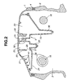
- oil droplets are scattered in a tangential direction from the camshaft 16.
- the oil droplets will strike against and be reflected on the inner surface or ceiling defining the inlet chamber 21; however, the oil droplets can be prevented from directly entering the gas inlet 26 upon being interrupted with the projection walls 41.
- the inner surface or ceiling defining the inlet chamber 21 is inclined, there is the fear that oil droplets moved upward to the ceiling are reflected on the ceiling toward the side of the gas inlet 26 if no projection wall 41 is provided.
- the projection walls 41 are parallelly arranged so that reflected oil droplets can be securely prevented from entering the gas inlet 26. Oil droplets struck and adhered to the projection walls 41 gradually grow to large oil droplets and drop from the projection walls 41 into the valve operating chamber 3 by its own weight.
- Fig. 2 it is possible to locate the opening 24 to be relatively close to the upper side of the camshaft 16, making it unnecessary to use a cover or the like for covering the under side of the opening 24.
- This not only makes the cylinder head cover 1 itself small-sized but also further lowers the level of the upper surface of the cylinder head cover 1 assembled in the internal combustion engine.
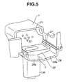
- the oil separator 5 is constituted of two members, i.e., the cylinder head cover 1 and the separator cover 15 which respectively molded with plastics, thereby facilitating assembly of the oil separator 5 while lowering the production cost of the oil separator 15.
Landscapes
- Engineering & Computer Science (AREA)
- Mechanical Engineering (AREA)
- General Engineering & Computer Science (AREA)
- Lubrication Details And Ventilation Of Internal Combustion Engines (AREA)
- Cylinder Crankcases Of Internal Combustion Engines (AREA)
Claims (7)
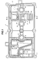
- Ölabscheider (5), der in Kombination mit einem Zylinderkopfdeckel (1) eines Verbrennungsmotors vorhanden ist, um Ölnebel von Kurbelgehäusegas zu trennen, das über den Zylinderkopfdeckel (1) ausgestoßen werden soll, wobei der Ölabscheider (5) umfasst:eine Abscheider-Abdeckung (15), die an einer Innenfläche des Zylinderkopfdeckels (1) befestigt ist und einen Raum begrenzt, der sich, in Draufsicht, in einer ersten Richtung senkrecht zur Achse einer Nockenwelle (16) zwischen der Abscheider-Abdeckung (15) und dem Zylinderkopfdeckel (1) erstreckt, wobei die Abscheider-Abdeckung (15) einen ersten Endabschnitt mit einer Öffnung (24) enthält, über die sich der Raum zu einer Ventilbetätigungskammer (3) öffnet;eine Trennwand (31), die in dem Raum eine Einlassseiten-Abscheiderkammer (22) undeine Auslassseiten-Abscheiderkammer (23) bildet, die an einander gegenüberliegenden Seiten der Trennwand (31) angeordnet sind, wobei die Einlassseiten-Abscheiderkammer (22) an die Öffnung (24) angrenzt, die Auslassseiten-Abscheiderkammer (23) durch einen zweiten Endabschnitt der Abscheider-Abdeckung (15) gebildet wird, der zweite Endabschnitt dem ersten Endabschnitt in der ersten Richtung gegenüber liegt, sich die Trennwand (31) in einer zweiten Richtung parallel zu der Achse der Nockenwelle (16) erstreckt und mit einer Vielzahl dünner Durchlässe (32) versehen ist, die durch die Trennwand (31) hindurch verlaufen; undeiner Vielzahl von Vorsprungswänden (41), die von einem Teil der Innenfläche des Zylinderkopfdeckels (1) vorstehen, der der Ventilbetätigungskammer über die Öffnung (24) zugewandt ist, wobei die Vorsprungswände (41) zu der Ventilbetätigungskammer (3) hin vorstehen und sich in der zweiten Richtung erstrecken und die Vorsprungswände (41) separat voneinander angeordnet sind.
- Ölabscheider (5) nach Anspruch 1, wobei die Vorsprungswände (41) und die Öffnung (24) der Abscheider-Abdeckung (15) oberhalb der Nockenwelle (16) angeordnet sind.
- Ölabscheider (5) nach Anspruch 1, wobei der Teil der Innenfläche des Zylinderkopfdeckels (1) so geneigt ist, dass die Höhe des Teils in einer Richtung zu der Einlassseiten-Abscheiderkammer (22) hin ansteigt.
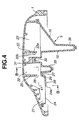
- Ölabscheider (5) nach Anspruch 1, der des Weiteren eine Trennwand (25) umfasst, die von der Innenfläche des Zylinderkopfdeckels (1) zu der Abscheider-Abdeckung (15) hin vorsteht, wobei die Trennwand (25) ein unteres Ende separat von der Abscheider-Abdeckung (15) hat, so dass ein schlitzartiger Gaseinlass (26) entsteht.
- Ölabscheider (5) nach Anspruch 4, wobei die Abscheider-Abdeckung (15) eine Einlasskammer-Bodenwand (28) hat, die die Einlasskammer (21) begrenzt, die zwischen der Öffnung (24) der Abscheider-Abdeckung (15) und dem schlitzartigen Gaseinlass (26) angeordnet ist, und die Einlasskammer-Bodenwand (28) so geneigt ist, dass die Höhe eines ersten Abschnitts niedriger ist als die eines zweiten Abschnitts, wobei der erste Abschnitt an die Öffnung (24) angrenzt und der zweite Abschnitt an den schlitzartigen Gaseinlass (26) angrenzt.
- Ölabscheider (5) nach Anspruch 5, wobei die Abscheider-Abdeckung (15) einen Absatzabschnitt (29) hat, der sich zwischen der Einlasskammer-Bodenwand (28) und dem schlitzartigen Gaseinlass (26) befindet, so dass der schlitzartige Gaseinlass (26) höher liegt als die Einlasskammer-Bodenwand (28).
- Ölabscheider (5) nach Anspruch 1, wobei die Abscheider-Abdeckung (15) ein aus Kunststoff bestehendes geformtes Element ist und der Zylinderkopfdeckel (1) ein aus Kunststoff bestehendes geformtes Element ist.
Applications Claiming Priority (2)
| Application Number | Priority Date | Filing Date | Title |
|---|---|---|---|
| JP2003354481 | 2003-10-15 | ||
| JP2003354481A JP4344579B2 (ja) | 2003-10-15 | 2003-10-15 | シリンダヘッドカバーのオイルセパレータ |
Publications (3)
| Publication Number | Publication Date |
|---|---|
| EP1524414A2 EP1524414A2 (de) | 2005-04-20 |
| EP1524414A3 EP1524414A3 (de) | 2010-03-31 |
| EP1524414B1 true EP1524414B1 (de) | 2011-08-17 |
Family
ID=34373565
Family Applications (1)
| Application Number | Title | Priority Date | Filing Date |
|---|---|---|---|
| EP04024303A Expired - Lifetime EP1524414B1 (de) | 2003-10-15 | 2004-10-12 | Ölabscheider in einem Zylinderkopfdeckel |
Country Status (4)
| Country | Link |
|---|---|
| US (1) | US7117858B2 (de) |
| EP (1) | EP1524414B1 (de) |
| JP (1) | JP4344579B2 (de) |
| CN (1) | CN1607320A (de) |
Cited By (2)
| Publication number | Priority date | Publication date | Assignee | Title |
|---|---|---|---|---|
| DE102013207631B4 (de) * | 2012-05-24 | 2020-12-17 | Toyota Boshoku Kabushiki Kaisha | Ölabscheider |
| DE112013002616B4 (de) | 2012-05-23 | 2021-08-26 | Honda Motor Co., Ltd. | Motorölabscheider mit Kopfdeckel-Prallplattensystem zur Verbesserung der Ölnebelabscheidung |
Families Citing this family (57)
| Publication number | Priority date | Publication date | Assignee | Title |
|---|---|---|---|---|
| US7441551B2 (en) | 2005-08-22 | 2008-10-28 | Honda Motor Co., Ltd. | Intake manifold |
| RU2300638C1 (ru) * | 2005-09-05 | 2007-06-10 | Открытое акционерное общество "Заволжский моторный завод" | Маслоотделитель системы вентиляции картера двигателя внутреннего сгорания с турбонаддувом |
| FR2895459A1 (fr) * | 2005-12-22 | 2007-06-29 | Renault Sas | Couvre culasse d'un bloc moteur comportant interieurement une chambre de pre-decantation, une chambre de decantation et un conduit de raccordement des deux chambres |
| CN100383365C (zh) * | 2006-03-08 | 2008-04-23 | 无锡开普动力有限公司 | 四冲程发动机的曲轴箱换气结构 |
| DE102006012611A1 (de) * | 2006-03-20 | 2007-09-27 | Mahle International Gmbh | Zylinderkopf eines Verbrennungsmotors |
| JP4169763B2 (ja) * | 2006-03-20 | 2008-10-22 | 小島プレス工業株式会社 | ブローバイガス用オイルセパレータ |
| DE102006019880A1 (de) * | 2006-04-28 | 2007-10-31 | Audi Ag | Motorgehäusedeckel eines Verbrennungsmotors mit Entlüftungssystem |
| JP4583338B2 (ja) * | 2006-06-05 | 2010-11-17 | 本田技研工業株式会社 | ベルト式伝動機構を備えるバーチカル内燃機関 |
| JP4690257B2 (ja) * | 2006-06-23 | 2011-06-01 | 株式会社マーレ フィルターシステムズ | オイルミストセパレータ |
| JP4623432B2 (ja) * | 2006-11-09 | 2011-02-02 | トヨタ自動車株式会社 | 内燃機関のスラッジ付着抑制構造 |
| US20080127953A1 (en) * | 2006-12-01 | 2008-06-05 | Toyota Engineering & Manufacturing North America, Inc. | Engine Head Cover Assembly Having An Integrated Oil Separator |
| DE102007010308A1 (de) | 2007-02-23 | 2008-08-28 | Dr. Ing. H.C. F. Porsche Aktiengesellschaft | Ölvorabscheider für Kurbelgehäusegas |
| EP1961928B1 (de) | 2007-02-23 | 2018-07-25 | Dr. Ing. h.c. F. Porsche AG | Ölvorabscheider für Kurbelgehäusegas |
| JP4978369B2 (ja) * | 2007-08-23 | 2012-07-18 | マツダ株式会社 | エンジンのオイル分離装置 |
| JP4960901B2 (ja) * | 2008-02-15 | 2012-06-27 | 富士重工業株式会社 | エンジンのブリーザ装置 |
| JP4954114B2 (ja) * | 2008-02-18 | 2012-06-13 | 愛知機械工業株式会社 | ブローバイガス還流構造およびこれを備える内燃機関 |
| JP4510108B2 (ja) * | 2008-03-13 | 2010-07-21 | 小島プレス工業株式会社 | ブローバイガス用オイルセパレータ |
| EP2348201B1 (de) * | 2008-06-27 | 2013-06-05 | BRP-Powertrain GmbH & Co. KG | Ölbehälteranordnung für Verbrennungsmotor |
| KR101014532B1 (ko) * | 2008-07-25 | 2011-02-14 | 기아자동차주식회사 | 블로우바이 가스의 오일 분리장치 |
| DE102008050038A1 (de) * | 2008-08-11 | 2010-02-18 | Elringklinger Ag | Partikel-Abscheidevorrichtung für eine Aerosol-Strömung |
| US8011338B2 (en) * | 2008-09-11 | 2011-09-06 | Ford Global Technologies, Llc | Camcover oil separator |
| JP2010096154A (ja) * | 2008-10-20 | 2010-04-30 | Aichi Mach Ind Co Ltd | 気液分離構造 |
| KR101052771B1 (ko) * | 2008-11-28 | 2011-08-01 | 쌍용자동차 주식회사 | 자동차용 실린더헤드커버 일체형 환기장치 |
| JP5290732B2 (ja) * | 2008-12-22 | 2013-09-18 | 株式会社マーレ フィルターシステムズ | 内燃機関のオイルセパレータ |
| KR101054035B1 (ko) * | 2009-05-15 | 2011-08-03 | 인지컨트롤스 주식회사 | 내연기관용 세퍼레이터 |
| JP2011074900A (ja) * | 2009-10-02 | 2011-04-14 | Toyota Motor Corp | エンジンのオイル分離装置 |
| EP2390477B1 (de) * | 2010-05-26 | 2012-12-05 | Fiat Powertrain Technologies S.p.A. | Abscheidevorrichtung für eine Entlüftungsvorrichtung einer Brennkraftmaschine |
| CN101900011B (zh) * | 2010-07-23 | 2012-10-24 | 奇瑞汽车股份有限公司 | 一种油气分离器 |
| JP5032641B2 (ja) * | 2010-09-06 | 2012-09-26 | 本田技研工業株式会社 | 車両用エンジン |
| JP5517899B2 (ja) * | 2010-12-01 | 2014-06-11 | 小島プレス工業株式会社 | オイルセパレータ |
| KR20120063803A (ko) * | 2010-12-08 | 2012-06-18 | 현대자동차주식회사 | 엔진용 벤틸레이션 헤드 커버 |
| US8347865B2 (en) | 2011-05-09 | 2013-01-08 | Ford Global Technologies, Llc | System and method for returning oil separated from engine crankcase gases |
| JP5847445B2 (ja) | 2011-06-08 | 2016-01-20 | 株式会社マーレ フィルターシステムズ | 内燃機関のオイルセパレータ |
| JP5890153B2 (ja) | 2011-11-21 | 2016-03-22 | 株式会社マーレ フィルターシステムズ | 内燃機関のオイルセパレータ |
| JP2013124598A (ja) * | 2011-12-15 | 2013-06-24 | Mahle Filter Systems Japan Corp | 内燃機関のヘッドカバー |
| EP2700791A1 (de) * | 2012-08-23 | 2014-02-26 | Dichtungstechnik G. Bruss GmbH & Co. KG | Ölabscheideranordnung und Zylinderkopfhaube für einen Verbrennungsmotor |
| CN103899381A (zh) * | 2012-12-27 | 2014-07-02 | 现代自动车株式会社 | 用于车辆的油滤系统 |
| JP5979080B2 (ja) * | 2013-05-28 | 2016-08-24 | トヨタ自動車株式会社 | 内燃機関のブローバイガス処理装置 |
| JP5689930B2 (ja) * | 2013-07-24 | 2015-03-25 | 株式会社工進 | エンジンの潤滑装置 |
| JP5949810B2 (ja) * | 2014-02-28 | 2016-07-13 | トヨタ自動車株式会社 | 内燃機関のブローバイガス処理装置 |
| US10443458B2 (en) * | 2014-05-14 | 2019-10-15 | Ford Global Technologies, Llc | Engine assembly with passageway for reducing oil leakage |
| CN103982321B (zh) * | 2014-05-30 | 2016-06-08 | 安徽江淮汽车股份有限公司 | 发动机缸盖护罩及发动机总成 |
| DE102014109075A1 (de) * | 2014-06-27 | 2015-12-31 | Elringklinger Ag | Zylinderkopfhaube und Verfahren zur Herstellung einer Zylinderkopfhaube |
| DE102014011355A1 (de) * | 2014-07-30 | 2016-02-04 | Neander Motors Ag | Brennkraftmaschine der Hubkolbenbauart |
| JP6413546B2 (ja) * | 2014-09-24 | 2018-10-31 | スズキ株式会社 | 内燃機関のオイル分離構造 |
| JP6347736B2 (ja) * | 2014-12-18 | 2018-06-27 | 株式会社マーレ フィルターシステムズ | オイルミストセパレータ |
| JP6412425B2 (ja) | 2014-12-18 | 2018-10-24 | 株式会社マーレ フィルターシステムズ | 内燃機関のオイルセパレータの入口構造 |
| JP6759980B2 (ja) * | 2016-10-28 | 2020-09-23 | トヨタ紡織株式会社 | オイルミストセパレータ |
| JP2018084144A (ja) * | 2016-11-21 | 2018-05-31 | ヤマハ発動機株式会社 | エンジン及び車両 |
| JP6729333B2 (ja) * | 2016-12-06 | 2020-07-22 | 三菱自動車工業株式会社 | シリンダヘッドカバーおよびそれを備えたエンジン |
| JP6790870B2 (ja) | 2017-01-25 | 2020-11-25 | トヨタ紡織株式会社 | オイルミストセパレータ |
| JP6549659B2 (ja) * | 2017-08-21 | 2019-07-24 | 本田技研工業株式会社 | 内燃機関のブリーザ装置 |
| JP6996321B2 (ja) * | 2018-02-01 | 2022-01-17 | トヨタ自動車株式会社 | 内燃機関 |
| CN110985163A (zh) * | 2019-12-31 | 2020-04-10 | 里卡多科技咨询(上海)有限公司 | 适用于发动机的油气分离装置 |
| CN112128011B (zh) * | 2020-09-16 | 2022-01-28 | 安徽江淮汽车集团股份有限公司 | 一种发动机缸盖护罩 |
| US20220154668A1 (en) * | 2020-11-18 | 2022-05-19 | Wayne Douglas Nixon | Universal valve cover |
| GB2620407A (en) * | 2022-07-06 | 2024-01-10 | Caterpillar Energy Solutions Gmbh | Lubrication device, cylinder head cover, cylinder head component, system thereof, and oil lubricated machine |
Family Cites Families (15)
| Publication number | Priority date | Publication date | Assignee | Title |
|---|---|---|---|---|
| JPS60143122U (ja) * | 1984-03-05 | 1985-09-21 | アイシン精機株式会社 | オイルセパレ−タ |
| JPS60192821A (ja) * | 1984-03-15 | 1985-10-01 | Honda Motor Co Ltd | 内燃機関のクランクケ−スベンチレ−シヨン装置 |
| JPS6218314U (de) * | 1985-07-19 | 1987-02-03 | ||
| JP2647951B2 (ja) * | 1989-02-28 | 1997-08-27 | ヤマハ発動機株式会社 | 車両用エンジンのブローバイガス回収装置 |
| US5129371A (en) * | 1991-09-03 | 1992-07-14 | Saturn Corporation | Cam cover oil separator for crankcase ventilation |
| JP3283687B2 (ja) | 1994-02-28 | 2002-05-20 | 株式会社テネックス | オイルミストセパレ−タ |
| DE29603254U1 (de) * | 1996-02-23 | 1997-07-17 | Robert Bosch Gmbh, 70469 Stuttgart | Zylinderkopfhaube einer Brennkraftmaschine |
| EP0860602B1 (de) * | 1997-02-21 | 2001-11-21 | Dichtungstechnik G. Bruss GmbH & Co. KG | Verfahren zum Herstellen einer Zylinderkopfhaube für eine Brennkraftmaschine und Zylinderkopfhaube |
| US6029638A (en) * | 1997-11-07 | 2000-02-29 | Honda Giken Kogyo Kabushiki Kaisha | Internal combustion engine with dry sump lubricating system |
| JP2000045750A (ja) | 1998-07-24 | 2000-02-15 | Uchiyama Mfg Corp | ロッカカバーのオイルセパレータ |
| JP2000045749A (ja) | 1998-07-31 | 2000-02-15 | Tennex Corp | ブローバイガスにおけるオイルの分離装置 |
| US6443136B1 (en) * | 2000-10-25 | 2002-09-03 | Honda Giken Kogyo Kabushiki Kaisha | Breather apparatus for an internal combustion engine |
| US6412478B1 (en) * | 2001-01-02 | 2002-07-02 | Generac Power Systems, Inc. | Breather for internal combustion engine |
| JP3967552B2 (ja) * | 2001-02-19 | 2007-08-29 | 本田技研工業株式会社 | エンジン用気液分離装置 |
| JP4176330B2 (ja) | 2001-06-19 | 2008-11-05 | 内浜化成株式会社 | オイルミストセパレータ |
-
2003
- 2003-10-15 JP JP2003354481A patent/JP4344579B2/ja not_active Expired - Fee Related
-
2004
- 2004-09-10 CN CN200410078404.9A patent/CN1607320A/zh active Pending
- 2004-10-12 EP EP04024303A patent/EP1524414B1/de not_active Expired - Lifetime
- 2004-10-14 US US10/963,743 patent/US7117858B2/en not_active Expired - Fee Related
Cited By (2)
| Publication number | Priority date | Publication date | Assignee | Title |
|---|---|---|---|---|
| DE112013002616B4 (de) | 2012-05-23 | 2021-08-26 | Honda Motor Co., Ltd. | Motorölabscheider mit Kopfdeckel-Prallplattensystem zur Verbesserung der Ölnebelabscheidung |
| DE102013207631B4 (de) * | 2012-05-24 | 2020-12-17 | Toyota Boshoku Kabushiki Kaisha | Ölabscheider |
Also Published As
| Publication number | Publication date |
|---|---|
| CN1607320A (zh) | 2005-04-20 |
| JP4344579B2 (ja) | 2009-10-14 |
| US7117858B2 (en) | 2006-10-10 |
| US20050092267A1 (en) | 2005-05-05 |
| EP1524414A3 (de) | 2010-03-31 |
| EP1524414A2 (de) | 2005-04-20 |
| JP2005120855A (ja) | 2005-05-12 |
Similar Documents
| Publication | Publication Date | Title |
|---|---|---|
| EP1524414B1 (de) | Ölabscheider in einem Zylinderkopfdeckel | |
| US7506629B2 (en) | Oil return structure for internal combustion engine | |
| US4958613A (en) | Internal combustion engine with crankcase ventilation system | |
| US4723529A (en) | Oil separator for a blowby gas ventilation system of an internal combustion engine | |
| JP4249504B2 (ja) | オイルセパレータ構造及びオイルセパレータユニット | |
| US20040244783A1 (en) | Crankcase emission control device | |
| CN101631946B (zh) | 内燃机的气缸盖罩 | |
| US6530367B2 (en) | Engine air-oil separator | |
| CN109424469B (zh) | 内燃机的通气装置 | |
| EP0868595B1 (de) | Eine flüssigkeit von gasabscheider und damit ausgerüstete brennkraftmaschine | |
| JP4639999B2 (ja) | 内燃機関のオイル戻し構造 | |
| US5975065A (en) | Venting arrangement for an internal combustion engine | |
| US8061336B2 (en) | PCV system for V-type engine | |
| JP2004162625A (ja) | ブローバイガス還流システムのオイルセパレータ | |
| JP2011058433A (ja) | エンジンのオイル分離装置 | |
| JP4918843B2 (ja) | ロッカカバーのオイルセパレータ構造 | |
| CN114991986A (zh) | 气缸盖罩以及发动机 | |
| JP3206241B2 (ja) | 内燃機関のオイルセパレータ構造 | |
| JP4036185B2 (ja) | エンジンのオイル分離装置 | |
| JP7248638B2 (ja) | 内燃機関 | |
| JPS6316812Y2 (de) | ||
| JP6524705B2 (ja) | シリンダヘッド構造 | |
| JP4117558B2 (ja) | 内燃機関のブリーザ装置 | |
| JPS6316811Y2 (de) | ||
| JP2025082688A (ja) | エンジン |
Legal Events
| Date | Code | Title | Description |
|---|---|---|---|
| PUAI | Public reference made under article 153(3) epc to a published international application that has entered the european phase |
Free format text: ORIGINAL CODE: 0009012 |
|
| 17P | Request for examination filed |
Effective date: 20041012 |
|
| AK | Designated contracting states |
Kind code of ref document: A2 Designated state(s): AT BE BG CH CY CZ DE DK EE ES FI FR GB GR HU IE IT LI LU MC NL PL PT RO SE SI SK TR |
|
| AX | Request for extension of the european patent |
Extension state: AL HR LT LV MK |
|
| RAP1 | Party data changed (applicant data changed or rights of an application transferred) |
Owner name: MAHLE FILTER SYSTEMS JAPAN CORPORATION |
|
| PUAL | Search report despatched |
Free format text: ORIGINAL CODE: 0009013 |
|
| AK | Designated contracting states |
Kind code of ref document: A3 Designated state(s): AT BE BG CH CY CZ DE DK EE ES FI FR GB GR HU IE IT LI LU MC NL PL PT RO SE SI SK TR |
|
| AX | Request for extension of the european patent |
Extension state: AL HR LT LV MK |
|
| 17Q | First examination report despatched |
Effective date: 20100728 |
|
| AKX | Designation fees paid |
Designated state(s): DE FR |
|
| RIC1 | Information provided on ipc code assigned before grant |
Ipc: F01M 13/04 20060101AFI20101203BHEP |
|
| GRAP | Despatch of communication of intention to grant a patent |
Free format text: ORIGINAL CODE: EPIDOSNIGR1 |
|
| GRAS | Grant fee paid |
Free format text: ORIGINAL CODE: EPIDOSNIGR3 |
|
| GRAA | (expected) grant |
Free format text: ORIGINAL CODE: 0009210 |
|
| AK | Designated contracting states |
Kind code of ref document: B1 Designated state(s): DE FR |
|
| REG | Reference to a national code |
Ref country code: DE Ref legal event code: R096 Ref document number: 602004033956 Country of ref document: DE Effective date: 20111020 |
|
| PLBE | No opposition filed within time limit |
Free format text: ORIGINAL CODE: 0009261 |
|
| STAA | Information on the status of an ep patent application or granted ep patent |
Free format text: STATUS: NO OPPOSITION FILED WITHIN TIME LIMIT |
|
| 26N | No opposition filed |
Effective date: 20120521 |
|
| REG | Reference to a national code |
Ref country code: DE Ref legal event code: R097 Ref document number: 602004033956 Country of ref document: DE Effective date: 20120521 |
|
| REG | Reference to a national code |
Ref country code: FR Ref legal event code: PLFP Year of fee payment: 12 |
|
| REG | Reference to a national code |
Ref country code: FR Ref legal event code: PLFP Year of fee payment: 13 |
|
| REG | Reference to a national code |
Ref country code: FR Ref legal event code: PLFP Year of fee payment: 14 |
|
| PGFP | Annual fee paid to national office [announced via postgrant information from national office to epo] |
Ref country code: FR Payment date: 20171023 Year of fee payment: 14 Ref country code: DE Payment date: 20171027 Year of fee payment: 14 |
|
| REG | Reference to a national code |
Ref country code: DE Ref legal event code: R119 Ref document number: 602004033956 Country of ref document: DE |
|
| PG25 | Lapsed in a contracting state [announced via postgrant information from national office to epo] |
Ref country code: DE Free format text: LAPSE BECAUSE OF NON-PAYMENT OF DUE FEES Effective date: 20190501 |
|
| PG25 | Lapsed in a contracting state [announced via postgrant information from national office to epo] |
Ref country code: FR Free format text: LAPSE BECAUSE OF NON-PAYMENT OF DUE FEES Effective date: 20181031 |