EP1524414B1 - Oil separator combined with cylinder head cover - Google Patents
Oil separator combined with cylinder head cover Download PDFInfo
- Publication number
- EP1524414B1 EP1524414B1 EP04024303A EP04024303A EP1524414B1 EP 1524414 B1 EP1524414 B1 EP 1524414B1 EP 04024303 A EP04024303 A EP 04024303A EP 04024303 A EP04024303 A EP 04024303A EP 1524414 B1 EP1524414 B1 EP 1524414B1
- Authority
- EP
- European Patent Office
- Prior art keywords
- separator
- cylinder head
- cover
- inlet
- chamber
- Prior art date
- Legal status (The legal status is an assumption and is not a legal conclusion. Google has not performed a legal analysis and makes no representation as to the accuracy of the status listed.)
- Expired - Lifetime
Links
- 238000005192 partition Methods 0.000 claims description 33
- 238000002485 combustion reaction Methods 0.000 claims description 15
- 239000003595 mist Substances 0.000 claims description 14
- 239000004033 plastic Substances 0.000 claims description 5
- 229920003023 plastic Polymers 0.000 claims description 5
- 239000003921 oil Substances 0.000 description 90
- 238000000926 separation method Methods 0.000 description 8
- 230000002093 peripheral effect Effects 0.000 description 7
- 239000004952 Polyamide Substances 0.000 description 2
- 229920002647 polyamide Polymers 0.000 description 2
- 230000000994 depressogenic effect Effects 0.000 description 1
- 238000007599 discharging Methods 0.000 description 1
- 238000003780 insertion Methods 0.000 description 1
- 230000037431 insertion Effects 0.000 description 1
- 239000010687 lubricating oil Substances 0.000 description 1
- 238000004519 manufacturing process Methods 0.000 description 1
- 238000012986 modification Methods 0.000 description 1
- 230000004048 modification Effects 0.000 description 1
- 238000000638 solvent extraction Methods 0.000 description 1
Images

Classifications
-
- F—MECHANICAL ENGINEERING; LIGHTING; HEATING; WEAPONS; BLASTING
- F01—MACHINES OR ENGINES IN GENERAL; ENGINE PLANTS IN GENERAL; STEAM ENGINES
- F01M—LUBRICATING OF MACHINES OR ENGINES IN GENERAL; LUBRICATING INTERNAL COMBUSTION ENGINES; CRANKCASE VENTILATING
- F01M13/00—Crankcase ventilating or breathing
- F01M13/04—Crankcase ventilating or breathing having means for purifying air before leaving crankcase, e.g. removing oil
- F01M13/0416—Crankcase ventilating or breathing having means for purifying air before leaving crankcase, e.g. removing oil arranged in valve-covers
Definitions
- oil droplets are scattered in a tangential direction from the camshaft 16.
- the oil droplets will strike against and be reflected on the inner surface or ceiling defining the inlet chamber 21; however, the oil droplets can be prevented from directly entering the gas inlet 26 upon being interrupted with the projection walls 41.
- the inner surface or ceiling defining the inlet chamber 21 is inclined, there is the fear that oil droplets moved upward to the ceiling are reflected on the ceiling toward the side of the gas inlet 26 if no projection wall 41 is provided.
- the projection walls 41 are parallelly arranged so that reflected oil droplets can be securely prevented from entering the gas inlet 26. Oil droplets struck and adhered to the projection walls 41 gradually grow to large oil droplets and drop from the projection walls 41 into the valve operating chamber 3 by its own weight.
- Fig. 2 it is possible to locate the opening 24 to be relatively close to the upper side of the camshaft 16, making it unnecessary to use a cover or the like for covering the under side of the opening 24.
- This not only makes the cylinder head cover 1 itself small-sized but also further lowers the level of the upper surface of the cylinder head cover 1 assembled in the internal combustion engine.
- the oil separator 5 is constituted of two members, i.e., the cylinder head cover 1 and the separator cover 15 which respectively molded with plastics, thereby facilitating assembly of the oil separator 5 while lowering the production cost of the oil separator 15.
Landscapes
- Engineering & Computer Science (AREA)
- Mechanical Engineering (AREA)
- General Engineering & Computer Science (AREA)
- Lubrication Details And Ventilation Of Internal Combustion Engines (AREA)
- Cylinder Crankcases Of Internal Combustion Engines (AREA)
Description
- This invention relates to improvements in an oil separator provided in combination with a cylinder head cover of an internal combustion engine to separate oil mist in blow-by gas to be discharged out of the engine through the cylinder head cover.
- As is well known, in an internal combustion engine of an automotive vehicle, blow-by gas containing unburnt gas component leaked into a crankcase from combustion chambers of the engine is again introduced or recirculated into the combustion chambers through an engine air intake system, together with fresh air taken in from the outside of the engine. In such recirculation of blow-by gas, blow-by gas flowing through the crankcase contains oil mist of lubricating oil. In order to prevent oil mist from being carried to the engine intake system, in general, an oil separator is provided in combination of a cylinder head cover as a single unit so that the blow-by gas is taken out from the engine after oil mist is separated from blow-by gas by the oil separator, as disclosed in
Japanese Patent Provisional Publication Nos. 2000-45750 7-243317 - Many oil separators provided in combination with the cylinder head cover have been proposed. In an arrangement of Patent Provisional Publication No. 2000-45750, an inner plate having a plurality of small holes for oil separation is horizontally disposed, in which blow-by gas passed through the small holes strike against projection portions formed at a ceiling surface. Accordingly, oil droplets separated are spread on the upper surface of the inner plate thereby clogging the small holes. This lowers an oil separation performance of the oil separator.
- In the arrangement of Patent Provisional Publication No. 7-243317, a cover-like inlet member is disposed at the bottom plane of an inlet opening which is open to the upper side of a camshaft in order to prevent oil droplets raised up by the camshaft from directly entering the inlet opening. This inlet member increases the whole height of the cylinder head cover by an amount corresponding to the inlet member.
- Document
JP 2000 045749 A - Document
JP 2003 001030 A - It is, therefore, an object of the present invention is to provide an improved oil separator provided in combination with a cylinder head cover of an internal combustion engine, which can effectively overcome drawbacks encountered in conventional oil separators provided in combination with a cylinder head cover.
- Another object of the present invention is to provide an improved oil separator provided in combination with a cylinder head cover of an internal combustion engine, which makes it possible to reduce the whole height of the cylinder head cover, while its fine passages for separation of oil mist can be effectively prevented from being clogged with separated oil mist so as to provide a stable oil separation performance.
- A further object of the present invention is to provide an improved oil separator provided in combination with a cylinder head cover of an internal combustion engine, whose vertical dimension can be minimized, while a partition wall formed with fine passages is vertically disposed.
- An aspect of the present invention resides in an oil separator provided in combination with a cylinder head cover of an internal combustion engine to separate oil mist from blow-by gas to be discharged out through the cylinder head cover. The oil separator comprises a separator cover fixed to an inner surface of the cylinder head cover defining a space extending in a first direction perpendicular to axis of a camshaft in plan, between the separator cover and the cylinder head cover. The separator cover includes a first end section having an opening through which the space is opened to a valve operating chamber. A partition wall is provided to define in the space an inlet-side separator chamber and an outlet-side separator chamber which are located on opposite sides of the partition wall. The inlet-side separator chamber is located adjacent the opening. The outlet-side separator chamber is defined by a second end section of the separator cover. The second end section is opposite to the first end section in the first direction. The partition wall extends in a second direction parallel with the axis of the camshaft and being formed with a plurality of fine passages which pass through the partition wall. Additionally, a plurality of projection walls project from a part of the inner surface of the cylinder head cover which faces the valve operating chamber through the opening. The projection walls project toward the valve operating chamber and extending in the second direction, the projection walls being located separate from each other.
- In the drawings, like reference numerals designate like parts and elements throughout all the figures:
-
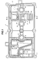
Fig. 1 is a bottom view of a cylinder head cover of an internal combustion engine, provided with an embodiment of an oil separator according to the present invention; -
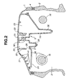
Fig. 2 is a vertical sectional view of the oil separator ofFig. 1 in the state of being installed to a cylinder head of the internal combustion engine; -
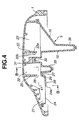
Fig. 3 is a vertical sectional view of the oil separator ofFig. 1 taken in the direction of arrows substantially along the line A-A ofFig. 1 ; -
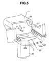
Fig. 4 is a vertical sectional view similar toFig. 3 but showing another embodiment of the oil separator according to the present invention; and -
Fig. 5 is a fragmentary perspective view of a part of the oil separator ofFig. 4 , cutout in the direction of arrows substantially along the line B-B ofFig. 4 . - Referring now to
Figs. 1 and2 , an embodiment of an oil separator according to the present invention is illustrated to be provided in combination with acylinder head cover 1 of an internal combustion engine. The internal combustion engine is of the in-line 4-cylinder type.Fig. 1 shows an inside arrangement of thecylinder head cover 1. Thiscylinder head cover 1 is installed together with aseal member 4 on a cylinder head 2 of the internal combustion engine as shown inFig. 2 , and defines avalve operating chamber 3 for accommodating a valve operating mechanism (not shown) of a so-called DOHC type. Thevalve operating chamber 3 is in communication with a crankcase of the side of a cylinder block (not shown). Blow-by gas flows from the crankcase to thevalve operating chamber 3 and then is guided to the outside of the engine through a blow-by gas passage (not shown) connected to thecylinder head cover 1. - The
cylinder head cover 1 is formed of plastic such as polyamide and includes a main body (not identified) which is formed generally dome-shaped. Thecylinder head cover 1 is provided with a peripheral section formed with sixbolt insertion holes 11 in which bolts (not shown) are respectively inserted for connection of the cylinder head cover with the cylinder head 2. Additionally, thecylinder head cover 1 is formed with fourspark plug holes 12 which are located at positions which respectively correspond to centers of cylinder bores of Nos. 1 to 4 engine cylinders (not shown). Spark plugs (not shown) are fixedly disposed respectively in thespark plug holes 12. Nos. 1 and 4 engine cylinders are located opposite to each other, in which Nos. 2 and 3 engine cylinders are located between the Nos. 1 and 4 engine cylinders. Theoil separator 5 of the present invention is located between the spark plug hole positioned corresponding to No. 1 engine cylinder and the spark plug hole positioned corresponding to No. 2 engine cylinder. Specifically, theoil separator 5 includes aseparator cover 15 which is formed of plastic such as polyamide and fabricated independently from thecylinder head cover 1. Theseparator cover 15 is installed to the inside surface at the top section and generally extends in a lateral direction of thecylinder head cover 1 or in a direction perpendicular to the axes ofcamshafts 16 in plan or inFig. 1 . More specifically, as shown inFig. 1 , theseparator cover 15 is generally L-shaped in plan, in which a main body section of theseparator cover 15 extends in the lateral direction of thecylinder head cover 1 while an auxiliary body section extends in a direction parallel to the axes of thecamshafts 16. The auxiliary body section of theseparator cover 15 extends to such a position as to cover a blow-gas discharge opening 17 formed in the main body of thecylinder head cover 1. A pipe (not shown) is connected to the blow-gas discharge opening 17. The main body section and the auxiliary body section of theseparator cover 15 define respectively a main chamber and an auxiliary chamber. The peripheral section of theseparator cover 15 is welded to a projection wall (not identified) projected from the inside surface of the main body of thecylinder head cover 1 and extending along a peripheral section of theseparator cover 15. - As shown in
Fig. 3 which is a cross-section taken along a line A-A ofFig. 1 , the inside (or the main chamber) of theoil separator 5 constructed of theseparator cover 15 and the main body of thecylinder head cover 1 includes aninlet chamber 21, an inlet-side separator chamber 22 and an outlet-side separator chamber 23. Theinlet chamber 21 is located at one end side of the extending main chamber of theoil separator 5. The outlet-side separator chamber 23 is located at the other end side of the extending main chamber of theoil separator 5. The inlet-side separator chamber 22 is located between theinlet chamber 21 and the outlet-side separator chamber 23. An end section of theseparator cover 15 defining theinlet chamber 21 is formed with a rectangular (in plan) opening 24 through which theinlet chamber 21 is open to thevalve operating chamber 3. Theopening 24 is defined by a rectangular (in plan) innerperipheral edge 24a of theseparator cover 15. While therectangular opening 24 has been shown leaving a generally frame-like peripheral portion, it will be understood that the opening may be formed by cut out a part of the end section of theseparator 15 defining theinlet chamber 21. - The
inlet chamber 21 and the inlet-side separator chamber 22 is separated from each other by apartition wall 25 which is projected downward from the inside surface (ceiling) of the main body of thecylinder head cover 1. The lower end of thepartition wall 25 is separate from a separatorchamber bottom wall 27 forming part of theseparator cover 15 and defining the inlet-side separator chamber 22, thereby forming a slit-like gas inlet 26. Thepartition wall 25 extends in a direction parallel with the axes of thecamshafts 16. An inletchamber bottom wall 28 is left between the innerperipheral edge 24a for theopening 24 and a gas inlet portion (not identified) of the separatorchamber bottom wall 27 defining thegas inlet 26. The inletchamber bottom wall 28 has a width (dimension in the direction perpendicular to the axes of thecamshafts 16 in plan) of about half of that of theopening 24. In other words, about 1/3 (in area) of the bottom part (located adjacent the above-mentioned gas inlet portion) of theinlet chamber 21 is covered with the inletchamber bottom wall 28, while the remaining about 2/3 (in area) of the bottom part of theinlet chamber 21 opens as theopening 24. The level or height position of the inletchamber bottom wall 28 is slightly lower than that of the separatorchamber bottom wall 27, thereby forming astep portion 29 between the above-mentioned gas inlet portion of the separatorchamber bottom wall 27 and the inletchamber bottom wall 28. One of thecamshafts 16 are located under theopening 24, in which the length (vertical dimension) of thepartition wall 25 and the length (horizontal dimension) of the inlet chamber bottom wall 28 (i.e., location of a part of the innerperipheral edge 24a of inlet chamber bottom wall 28) are set to prevent oil droplets tangentially scattered from the rotatingcamshaft 16 from directly entering thegas inlet 26. - The inlet-
side separator chamber 22 and the outlet-side separator chamber 23 are separated from each other by apartition wall 31 forming part of theseparator cover 15. Thepartition wall 31 extends laterally or in a direction parallel with the axes of thecamshafts 16, and extends upwardly to reach the inside surface of the main body of thecylinder head cover 1. Thepartition wall 31 is formed with a plurality offine passages 32 which extend horizontally or in a direction perpendicular to the axes of thecamshafts 16 in plan. Eachfine passage 32 passes through thepartition wall 31. It will be understood that thepartition wall 31 is formed relatively thick in order to ensure a certain length of thefine passages 32. While thepartition wall 31 has been shown and described as being integrally formed as a part of theseparator cover 15, it will be understood that thepartition wall 31 is not limited to have such a structure, and therefore thepartition wall 31 may be formed as a separate part independent from theseparator cover 15. - The
partition wall 31 formed with thefine passages 32 serves as a kind of filter so as to accomplish separation of oil mist. Anuneven plate 33 is formed integral with thecylinder head cover 1 and extends downward. Theuneven plate 33 is located opposite to thepartition wall 31 so in such a manner as to be slightly separate from thepartition wall 3, so that it is generally parallel with thepartition wall 31. Theuneven plate 33 is formed at a surface facing thepartition wall 31 with a plurality oflinear grooves 33a andlinear projections 33b which extend vertically or in a direction perpendicular to the axes of thecamshafts 16, in a plane perpendicular to the axes of thecamshafts 16. Each of theliner grooves 33a and each of thelinear projections 33b are located alternately so that alinear projection 33b is located between adjacent twolinear grooves 33a. Accordingly, flow of blow-by gas passed through thefine passages 32 then strike against the uneven surface of theuneven plate 33. More specifically, a part of blow-by gas strikes against the top surfaces of thelinear projections 33b upon being diffused, while the remaining part advances into thelinear grooves 33a and then strikes against the bottom surface of eachliner groove 33a and the side surfaces of thelinear grooves 33a a plurality of times, in which oil mist is separated every strikes. Blow-by gas struck against thelinear grooves 33a and thelinear projections 33b moves upward or downward along thelinear grooves 33a andprojections 33b, and then flows into the outlet-side separator chamber 23. - A
drain pipe 35 is formed integral with the separatorchamber bottom wall 27 and extends downward in order to drain oil droplets separated from blow-by gas to the side of thevalve operating chamber 3. The inside of thedrain pipe 35 is contiguous with the bottom part of the inlet-side separator chamber 22. Thedrain pipe 35 is generally in the shape of a flattened cylinder as seen fromFig. 1 , and extends into thevalve operating chamber 3. Thedrain pipe 35 has a tip end section formed with a small discharge opening (not identified) through which the separated oil droplets are discharged into thevalve operating chamber 3. Similarly, adrain pipe 36 is formed integral with a separator chamber bottom wall (of the separator cover 15) defining the outlet-side separator chamber 23 and extends downward in order to drain oil droplets separated from blow-by gas to the side of thevalve operating chamber 3. The outlet-side separator chamber 23 is formed generally L-shaped in plan and extends to the side of the No. 1 engine cylinder as shown inFig. 1 . The blow-by gas discharge opening 17 formed in thecylinder head cover 1 is in communication with the outlet-side separator chamber 23. - A plurality of
projection walls 41 are formed at a part (defining the inlet chamber 21) of the inside surface or ceiling of the main body of thecylinder head cover 1 and extend downward or in a direction parallel with the axes of thecamshafts 16. Theprojection walls 41 are arranged parallel with each other and spaced from each other with a suitable distance between theadjacent projection walls 41. In this embodiment, fourprojection walls 41 are formed at equal intervals in a part of the inside surface of the main body of thecylinder head cover 1 which part corresponds to theopening 24. The part of the inside surface of the main body of thecylinder head cover 1 is inclined in a direction perpendicular to the axes of thecamshafts 16 on the plane perpendicular to the axes of thecamshafts 16, thereby forming inclined inner and outer surface of the main body of thecylinder head cover 1. The inclined outer surface of the main body of thecylinder head cover 1 is provided to avoid the interference with an EGR valve (not shown) of an exhaust system of the engine. In other words, a space above the inclined outer surface of the main body of thecylinder head cover 1 is for the EGR valve. Thus, the main body of thecylinder head cover 1 is formed partly depressed to provide the space for the EGR valve. - With the
oil separator 5 arranged as discussed above, when blow-by gas within thevalve operating chamber 3 moves toward the blow-by gas discharge opening 17, it first goes to theinlet chamber 21 through theopening 24 and then passes through the slit-like gas inlet 26 to enter the inlet-side separator chamber 22. As will be understood, even during a time where blow-by gas flows from theinlet chamber 21 to the inlet-side separator chamber 22, a certain amount of oil mist can be separated to form oil droplets. Then, oil mist is effectively separated upon passing of blow-gas through thefine passages 32, and further separated upon striking of blow-by gas against the uneven surface of theuneven plate 33 after passing of blow-gas through thefine passages 32, thereby forming oil droplets at the bottom part of the inlet-side and outlet-side separator chambers side separator chamber 23 is considerably large, the flow rate of blow-by gas lowers so that oil mist is separated here by its own weight thereby forming oil droplets. The oil droplets are collected at the bottom parts of the respective inlet-side and outlet-side separator chambers valve operating chamber 3 through thedrain pipes oil separator 5, blow-by gas basically flows along the width direction of thecylinder head cover 1 or the lateral direction perpendicular to the axes of thecamshafts 16, and therefore a sufficiently long passage for blow-by gas can be ensured in a region from theinlet chamber 21 to the blow-by gas discharge opening 17, thereby providing a good oil separation performance. Oil droplets adhered to the vertically disposedpartition wall 31 smoothly flows down along the surface of thepartition wall 31, thereby preventing thefine passages 32 from being clogged with oil droplets thus providing a stable oil separation performance. - Additionally, with rotation of the
camshaft 16 located under theopening 24 of theseparator cover 15, oil droplets are scattered in a tangential direction from thecamshaft 16. The oil droplets will strike against and be reflected on the inner surface or ceiling defining theinlet chamber 21; however, the oil droplets can be prevented from directly entering thegas inlet 26 upon being interrupted with theprojection walls 41. Particularly in case that the inner surface or ceiling defining theinlet chamber 21 is inclined, there is the fear that oil droplets moved upward to the ceiling are reflected on the ceiling toward the side of thegas inlet 26 if noprojection wall 41 is provided. According to this embodiment, theprojection walls 41 are parallelly arranged so that reflected oil droplets can be securely prevented from entering thegas inlet 26. Oil droplets struck and adhered to theprojection walls 41 gradually grow to large oil droplets and drop from theprojection walls 41 into thevalve operating chamber 3 by its own weight. - Thus, according to this embodiment, as shown in
Fig. 2 , it is possible to locate theopening 24 to be relatively close to the upper side of thecamshaft 16, making it unnecessary to use a cover or the like for covering the under side of theopening 24. This not only makes thecylinder head cover 1 itself small-sized but also further lowers the level of the upper surface of thecylinder head cover 1 assembled in the internal combustion engine. - Furthermore, according to this embodiment, the
oil separator 5 is constituted of two members, i.e., thecylinder head cover 1 and theseparator cover 15 which respectively molded with plastics, thereby facilitating assembly of theoil separator 5 while lowering the production cost of theoil separator 15. - As discussed above, two (first and second) blow-by gas paths are required for recirculation of blow-by gas into the engine cylinders, in which fresh air is introduced into the engine cylinders through one (first) blow-by gas path in a low and medium load engine operating range of the engine. The
above oil separator 5 is provided for the first blow-by gas path which serves also as a fresh air introduction passage for introducing fresh air into the engine cylinders. As shown inFig. 1 , anotheroil separator 6 is provided between thespark plug hole 12 corresponding to the No. 3 engine cylinder and thespark plug hole 12 corresponding to the No. 4 engine cylinder. A second blow-by gas path provided with a so-called PCV valve is connected to thisoil separator 6. -
Figs. 4 and5 illustrate another embodiment of the oil separator according to the present invention, similar to the above embodiment ofFigs. 1 to 3 except for being partially modified. - In this embodiment, the inlet
chamber bottom wall 28 adjacent theopening 24 of theseparator cover 15 does not form a horizontal surface, and forms an inclined surface which is low in level at the side of theopening 24 as compared with at the opposite side. More specifically, as clearly shown inFig. 5 , the inletchamber bottom wall 28 includes first and second rectangular plate-like sections which are integrally connected to each other to form an upper surface which is generally V-shaped in cross-section so that a trough line T is formed between the first and second rectangular plate-like sections. The trough line T gradually lowers in level in a direction toward theopening 24. As same as in the above embodiment ofFigs. 1 to 3 , thestep portion 29 is provided between the gas inlet portion of the separatorchamber bottom wall 27 and the inletchamber bottom wall 28.Fig. 5 is a fragmentary perspective view of a part of theoil separator 5 combined with thecylinder head cover 1, cutout generally along the line B-B ofFig. 4 for the purpose of facilitating understanding of the oil separator of this embodiment. - With this arrangement, for example, in case that oil mist strikes against the ceiling of the
inlet chamber 21 and drops as oil droplets on the inletchamber bottom wall 28, the oil droplets tend to readily flow down along the inclined surface of the inletchamber bottom wall 28, thereby preventing the oil droplets from entering the inlet-side separator chamber 22 through thegas inlet 26. Particularly, oil droplets on the inletchamber bottom wall 28 is liable to be pushed toward thegas inlet 26 under the action of blow-by gas flowing from theopening 24 toward thegas inlet 26. However, since thestep section 29 exists between the inletchamber bottom wall 28 and thegas inlet 26, and therefore the oil droplets can be securely dammed up so that they flow down along the inclined surface of the inletchamber bottom wall 28 upon the oil droplets growing into somewhat large oil droplets. - As appreciated from the above, according to the present invention, it is unnecessary to provide a separate cover member or the like below the
opening 24 of the separator cover so that theopening 24 is open to the lower side as it is. Consequently, the vertical dimension of the oil separator can be minimized thereby reducing the whole height of the cylinder head cover. Additionally, blow-by gas passes in a lateral direction through the fine passages formed in the vertically disposed partition wall, and therefore the fine passages of the partition wall can be prevented from being clogged with separated oil droplets thereby obtaining a stable oil separation performance. - Although the invention has been described above by reference to certain embodiments of the invention, the invention is not limited to the embodiments described above. Modifications and variations of the embodiments described above will occur to those skilled in the art, in light of the above teachings. The scope of the invention is defined with reference to the following claims.
Claims (7)
- An oil separator (5) provided in combination with a cylinder head cover (1) of an internal combustion engine to separate oil mist from blow-by gas to be discharged out through the cylinder head cover (1), the oil separator (5) comprising:a separator cover (15) fixed to an inner surface of the cylinder head cover (1) defining a space extending in a first direction perpendicular to axis of a camshaft (16) in plan, between the separator cover (15) and the cylinder head cover (1), the separator cover (15) including a first end section having an opening (24) through which the space is opened to a valve operating chamber (3);a partition wall (31) defining in the space an inlet-side separator chamber (22) and an outlet-side separator chamber (23) which are located on opposite sides of the partition wall (31), the inlet-side separator chamber (22) being located adjacent the opening (24), the outlet-side separator chamber (23) being defined by a second end section of the separator cover (15), the second end section being opposite to the first end section in the first direction, the partition wall (31) extending in a second direction parallel with the axis of the camshaft (16) and being formed with a plurality of fine passages (32) which pass through the partition wall (31); anda plurality of projection walls (41) projecting from a part of the inner surface of the cylinder head cover (1) which faces the valve operating chamber through the opening (24), the projection walls (41) projecting toward the valve operating chamber (3) and extending in the second direction, the projection walls (41) being located separate from each other.
- An oil separator (5) as claimed in Claim 1, wherein the projection walls (41) and the opening (24) of the separator cover (15) are located above the camshaft (16).
- An oil separator (5) as claimed in Claim 1, wherein the part of the inner surface of the cylinder head cover (1) is inclined in a manner that level of the part rises in a direction toward the inlet-side separator chamber (22).
- An oil separator (5) as claimed in Claim 1, further comprising a partition wall (25) projecting from the inner surface of the cylinder head cover (1) toward the separator cover (15), the partition wall (25) having a lower end separate from the separator cover (15) to form a slit-like gas inlet (26).
- An oil separator (5) as claimed in Claim 4, wherein the separator cover (15) has an inlet chamber bottom wall (28) defining the inlet chamber (21), located between the opening (24) of the separator cover (15) and the slit-like gas inlet (26), the inlet chamber bottom wall (28) inclining in a manner that a first portion is lower in level than a second portion, the first portion being adjacent the opening (24), the second portion being adjacent the slit-like gas inlet (26).
- An oil separator (5) as claimed in Claim 5, wherein the separator cover (15) has a step portion (29) located between the inlet chamber bottom wall (28) and the slit-like gas inlet (26) so that the slit-like gas inlet (26) is located higher in level than the inlet chamber bottom wall (28).
- An oil separator (5) as claimed in Claim 1, wherein the separator cover (15) is a molded member formed of plastic, wherein the cylinder head cover (1) is a molded member formed of plastic.
Applications Claiming Priority (2)
| Application Number | Priority Date | Filing Date | Title |
|---|---|---|---|
| JP2003354481A JP4344579B2 (en) | 2003-10-15 | 2003-10-15 | Cylinder head cover oil separator |
| JP2003354481 | 2003-10-15 |
Publications (3)
| Publication Number | Publication Date |
|---|---|
| EP1524414A2 EP1524414A2 (en) | 2005-04-20 |
| EP1524414A3 EP1524414A3 (en) | 2010-03-31 |
| EP1524414B1 true EP1524414B1 (en) | 2011-08-17 |
Family
ID=34373565
Family Applications (1)
| Application Number | Title | Priority Date | Filing Date |
|---|---|---|---|
| EP04024303A Expired - Lifetime EP1524414B1 (en) | 2003-10-15 | 2004-10-12 | Oil separator combined with cylinder head cover |
Country Status (4)
| Country | Link |
|---|---|
| US (1) | US7117858B2 (en) |
| EP (1) | EP1524414B1 (en) |
| JP (1) | JP4344579B2 (en) |
| CN (1) | CN1607320A (en) |
Cited By (2)
| Publication number | Priority date | Publication date | Assignee | Title |
|---|---|---|---|---|
| DE102013207631B4 (en) * | 2012-05-24 | 2020-12-17 | Toyota Boshoku Kabushiki Kaisha | OIL SEPARATOR |
| DE112013002616B4 (en) | 2012-05-23 | 2021-08-26 | Honda Motor Co., Ltd. | Engine oil separator with head cover flapper system to improve oil mist separation |
Families Citing this family (58)
| Publication number | Priority date | Publication date | Assignee | Title |
|---|---|---|---|---|
| US7441551B2 (en) | 2005-08-22 | 2008-10-28 | Honda Motor Co., Ltd. | Intake manifold |
| RU2300638C1 (en) * | 2005-09-05 | 2007-06-10 | Открытое акционерное общество "Заволжский моторный завод" | Oil separator of turbocharged engine crankcase ventilation system |
| FR2895459A1 (en) * | 2005-12-22 | 2007-06-29 | Renault Sas | CYLINDER COVER OF A MOTOR BLOCK COMPRISING INTERIORLY A PRE-DECANTATION CHAMBER, A DECANTATION CHAMBER AND A CONNECTION DUCT OF THE TWO CHAMBERS |
| CN100383365C (en) * | 2006-03-08 | 2008-04-23 | 无锡开普动力有限公司 | Crankcase ventilation structure of four-stroke engine |
| DE102006012611A1 (en) * | 2006-03-20 | 2007-09-27 | Mahle International Gmbh | Cylinder head of an internal combustion engine |
| JP4169763B2 (en) * | 2006-03-20 | 2008-10-22 | 小島プレス工業株式会社 | Oil separator for blow-by gas |
| DE102006019880A1 (en) * | 2006-04-28 | 2007-10-31 | Audi Ag | Motor housing cover for internal combustion engine, has inlet opening for exhaust medium that is conducted by exhaust system, and part of oil separator housing formed integrally with cover |
| JP4583338B2 (en) * | 2006-06-05 | 2010-11-17 | 本田技研工業株式会社 | Vertical internal combustion engine having a belt-type transmission mechanism |
| JP4690257B2 (en) * | 2006-06-23 | 2011-06-01 | 株式会社マーレ フィルターシステムズ | Oil mist separator |
| JP4623432B2 (en) * | 2006-11-09 | 2011-02-02 | トヨタ自動車株式会社 | Sludge adhesion suppression structure for internal combustion engines |
| US20080127953A1 (en) * | 2006-12-01 | 2008-06-05 | Toyota Engineering & Manufacturing North America, Inc. | Engine Head Cover Assembly Having An Integrated Oil Separator |
| EP1961928B1 (en) | 2007-02-23 | 2018-07-25 | Dr. Ing. h.c. F. Porsche AG | Oil pre-filter for crankcase gas |
| DE102007010308A1 (en) | 2007-02-23 | 2008-08-28 | Dr. Ing. H.C. F. Porsche Aktiengesellschaft | Oil pre-filter for crankcase gas of internal-combustion engine, has shell body arranged in inner side of cylinder head cover, where shell body has inlet section which has flow cross-section increasing by inlet opening for crankcase gas |
| JP4978369B2 (en) * | 2007-08-23 | 2012-07-18 | マツダ株式会社 | Engine oil separator |
| JP4960901B2 (en) * | 2008-02-15 | 2012-06-27 | 富士重工業株式会社 | Engine breather equipment |
| JP4954114B2 (en) * | 2008-02-18 | 2012-06-13 | 愛知機械工業株式会社 | Blowby gas recirculation structure and internal combustion engine having the same |
| JP4510108B2 (en) * | 2008-03-13 | 2010-07-21 | 小島プレス工業株式会社 | Oil separator for blow-by gas |
| WO2009155997A1 (en) * | 2008-06-27 | 2009-12-30 | Brp-Rotax Gmbh & Co. Kg | Internal combustion engine oil tank arrangement |
| KR101014532B1 (en) * | 2008-07-25 | 2011-02-14 | 기아자동차주식회사 | Blow off gas oil separator |
| DE102008050039A1 (en) * | 2008-08-11 | 2010-02-18 | Elringklinger Ag | Particle separation device for an aerosol flow |
| US8011338B2 (en) * | 2008-09-11 | 2011-09-06 | Ford Global Technologies, Llc | Camcover oil separator |
| JP2010096154A (en) * | 2008-10-20 | 2010-04-30 | Aichi Mach Ind Co Ltd | Vapor-liquid separating structure |
| KR101052771B1 (en) * | 2008-11-28 | 2011-08-01 | 쌍용자동차 주식회사 | Automobile cylinder head cover integrated ventilation device |
| JP5290732B2 (en) * | 2008-12-22 | 2013-09-18 | 株式会社マーレ フィルターシステムズ | Oil separator for internal combustion engine |
| KR101054035B1 (en) * | 2009-05-15 | 2011-08-03 | 인지컨트롤스 주식회사 | Separators for Internal Combustion Engines |
| JP2011074900A (en) * | 2009-10-02 | 2011-04-14 | Toyota Motor Corp | Oil separation device of engine |
| EP2390477B1 (en) * | 2010-05-26 | 2012-12-05 | Fiat Powertrain Technologies S.p.A. | Separator device for a system for recirculation of the blow-by gases of an internal combustion engine |
| CN101900011B (en) * | 2010-07-23 | 2012-10-24 | 奇瑞汽车股份有限公司 | Gas and oil separator |
| JP5032641B2 (en) * | 2010-09-06 | 2012-09-26 | 本田技研工業株式会社 | Vehicle engine |
| JP5517899B2 (en) * | 2010-12-01 | 2014-06-11 | 小島プレス工業株式会社 | Oil separator |
| KR20120063803A (en) * | 2010-12-08 | 2012-06-18 | 현대자동차주식회사 | Ventilation head cover of engine |
| US8347865B2 (en) | 2011-05-09 | 2013-01-08 | Ford Global Technologies, Llc | System and method for returning oil separated from engine crankcase gases |
| JP5847445B2 (en) | 2011-06-08 | 2016-01-20 | 株式会社マーレ フィルターシステムズ | Oil separator for internal combustion engine |
| JP5890153B2 (en) * | 2011-11-21 | 2016-03-22 | 株式会社マーレ フィルターシステムズ | Oil separator for internal combustion engine |
| JP2013124598A (en) * | 2011-12-15 | 2013-06-24 | Mahle Filter Systems Japan Corp | Head cover of internal combustion engine |
| EP2700791A1 (en) * | 2012-08-23 | 2014-02-26 | Dichtungstechnik G. Bruss GmbH & Co. KG | Oil separation assembly and cylinder head cover for a combustion engine |
| CN103899381A (en) * | 2012-12-27 | 2014-07-02 | 现代自动车株式会社 | Oil filter system for vehicle |
| JP5979080B2 (en) * | 2013-05-28 | 2016-08-24 | トヨタ自動車株式会社 | Blow-by gas processing device for internal combustion engine |
| JP5689930B2 (en) * | 2013-07-24 | 2015-03-25 | 株式会社工進 | Engine lubrication equipment |
| JP5949810B2 (en) * | 2014-02-28 | 2016-07-13 | トヨタ自動車株式会社 | Blow-by gas processing device for internal combustion engine |
| US10443458B2 (en) * | 2014-05-14 | 2019-10-15 | Ford Global Technologies, Llc | Engine assembly with passageway for reducing oil leakage |
| CN103982321B (en) * | 2014-05-30 | 2016-06-08 | 安徽江淮汽车股份有限公司 | Motor cylinder protective shield and engine assembly |
| DE102014109075A1 (en) | 2014-06-27 | 2015-12-31 | Elringklinger Ag | Cylinder head cover and method for producing a cylinder head cover |
| DE102014011355A1 (en) * | 2014-07-30 | 2016-02-04 | Neander Motors Ag | Reciprocating internal combustion engine |
| JP6413546B2 (en) * | 2014-09-24 | 2018-10-31 | スズキ株式会社 | Oil separation structure of internal combustion engine |
| JP6347736B2 (en) * | 2014-12-18 | 2018-06-27 | 株式会社マーレ フィルターシステムズ | Oil mist separator |
| JP6412425B2 (en) * | 2014-12-18 | 2018-10-24 | 株式会社マーレ フィルターシステムズ | Oil separator inlet structure of internal combustion engine |
| JP6759980B2 (en) * | 2016-10-28 | 2020-09-23 | トヨタ紡織株式会社 | Oil mist separator |
| JP2018084144A (en) * | 2016-11-21 | 2018-05-31 | ヤマハ発動機株式会社 | Engine and vehicle |
| JP6729333B2 (en) * | 2016-12-06 | 2020-07-22 | 三菱自動車工業株式会社 | Cylinder head cover and engine equipped with the same |
| JP6790870B2 (en) | 2017-01-25 | 2020-11-25 | トヨタ紡織株式会社 | Oil mist separator |
| JP6549659B2 (en) * | 2017-08-21 | 2019-07-24 | 本田技研工業株式会社 | Breather device for internal combustion engine |
| JP6996321B2 (en) * | 2018-02-01 | 2022-01-17 | トヨタ自動車株式会社 | Internal combustion engine |
| CN110985163A (en) * | 2019-12-31 | 2020-04-10 | 里卡多科技咨询(上海)有限公司 | Oil-gas separation device suitable for engine |
| DE102020004533A1 (en) * | 2020-07-27 | 2022-01-27 | Cellcentric Gmbh & Co. Kg | liquid separator |
| CN112128011B (en) * | 2020-09-16 | 2022-01-28 | 安徽江淮汽车集团股份有限公司 | Engine cylinder cover shield |
| US20220154668A1 (en) * | 2020-11-18 | 2022-05-19 | Wayne Douglas Nixon | Universal valve cover |
| GB2620407A (en) * | 2022-07-06 | 2024-01-10 | Caterpillar Energy Solutions Gmbh | Lubrication device, cylinder head cover, cylinder head component, system thereof, and oil lubricated machine |
Family Cites Families (15)
| Publication number | Priority date | Publication date | Assignee | Title |
|---|---|---|---|---|
| JPS60143122U (en) * | 1984-03-05 | 1985-09-21 | アイシン精機株式会社 | oil separator |
| JPS60192821A (en) * | 1984-03-15 | 1985-10-01 | Honda Motor Co Ltd | Crankcase ventilation device for internal combustion engines |
| JPS6218314U (en) * | 1985-07-19 | 1987-02-03 | ||
| JP2647951B2 (en) * | 1989-02-28 | 1997-08-27 | ヤマハ発動機株式会社 | Blow-by gas recovery device for vehicle engine |
| US5129371A (en) * | 1991-09-03 | 1992-07-14 | Saturn Corporation | Cam cover oil separator for crankcase ventilation |
| JP3283687B2 (en) | 1994-02-28 | 2002-05-20 | 株式会社テネックス | Oil mist separator |
| DE29603254U1 (en) * | 1996-02-23 | 1997-07-17 | Robert Bosch Gmbh, 70469 Stuttgart | Cylinder head cover of an internal combustion engine |
| EP0860602B1 (en) * | 1997-02-21 | 2001-11-21 | Dichtungstechnik G. Bruss GmbH & Co. KG | Method for making a cylinder head cover for an internal combustion engine and cylinder head cover |
| US6029638A (en) * | 1997-11-07 | 2000-02-29 | Honda Giken Kogyo Kabushiki Kaisha | Internal combustion engine with dry sump lubricating system |
| JP2000045750A (en) | 1998-07-24 | 2000-02-15 | Uchiyama Mfg Corp | Oil separator for locker cover |
| JP2000045749A (en) | 1998-07-31 | 2000-02-15 | Tennex Corp | Oil separator for blow-by gas |
| US6443136B1 (en) * | 2000-10-25 | 2002-09-03 | Honda Giken Kogyo Kabushiki Kaisha | Breather apparatus for an internal combustion engine |
| US6412478B1 (en) * | 2001-01-02 | 2002-07-02 | Generac Power Systems, Inc. | Breather for internal combustion engine |
| JP3967552B2 (en) * | 2001-02-19 | 2007-08-29 | 本田技研工業株式会社 | Gas-liquid separator for engines |
| JP4176330B2 (en) | 2001-06-19 | 2008-11-05 | 内浜化成株式会社 | Oil mist separator |
-
2003
- 2003-10-15 JP JP2003354481A patent/JP4344579B2/en not_active Expired - Fee Related
-
2004
- 2004-09-10 CN CN200410078404.9A patent/CN1607320A/en active Pending
- 2004-10-12 EP EP04024303A patent/EP1524414B1/en not_active Expired - Lifetime
- 2004-10-14 US US10/963,743 patent/US7117858B2/en not_active Expired - Fee Related
Cited By (2)
| Publication number | Priority date | Publication date | Assignee | Title |
|---|---|---|---|---|
| DE112013002616B4 (en) | 2012-05-23 | 2021-08-26 | Honda Motor Co., Ltd. | Engine oil separator with head cover flapper system to improve oil mist separation |
| DE102013207631B4 (en) * | 2012-05-24 | 2020-12-17 | Toyota Boshoku Kabushiki Kaisha | OIL SEPARATOR |
Also Published As
| Publication number | Publication date |
|---|---|
| JP2005120855A (en) | 2005-05-12 |
| US7117858B2 (en) | 2006-10-10 |
| US20050092267A1 (en) | 2005-05-05 |
| EP1524414A2 (en) | 2005-04-20 |
| EP1524414A3 (en) | 2010-03-31 |
| CN1607320A (en) | 2005-04-20 |
| JP4344579B2 (en) | 2009-10-14 |
Similar Documents
| Publication | Publication Date | Title |
|---|---|---|
| EP1524414B1 (en) | Oil separator combined with cylinder head cover | |
| US7506629B2 (en) | Oil return structure for internal combustion engine | |
| US4958613A (en) | Internal combustion engine with crankcase ventilation system | |
| US4723529A (en) | Oil separator for a blowby gas ventilation system of an internal combustion engine | |
| JP4249504B2 (en) | Oil separator structure and oil separator unit | |
| EP1467069B1 (en) | Crankcase emission control device | |
| CN109424469B (en) | Breather device for internal combustion engine | |
| CN101631946B (en) | Head cover for internal combustion engine | |
| US6530367B2 (en) | Engine air-oil separator | |
| JP4639999B2 (en) | Oil return structure for internal combustion engine | |
| US5975065A (en) | Venting arrangement for an internal combustion engine | |
| US8061336B2 (en) | PCV system for V-type engine | |
| JP2004162625A (en) | Oil separator of blow-by gas reflux system | |
| JP2511862Y2 (en) | Cylinder head cover of internal combustion engine | |
| JP2011058433A (en) | Oil separating device for engine | |
| JP4918843B2 (en) | Rocker cover oil separator structure | |
| CN114991986A (en) | Cylinder head cover and engine | |
| JP3206241B2 (en) | Oil separator structure of internal combustion engine | |
| JP4036185B2 (en) | Engine oil separator | |
| JPS6316812Y2 (en) | ||
| JP6524705B2 (en) | Cylinder head structure | |
| JP4117558B2 (en) | Breather device for internal combustion engine | |
| JPS6316811Y2 (en) | ||
| JP2025082688A (en) | engine | |
| KR100187523B1 (en) | Blow-by-gas filter for vehicle engines |
Legal Events
| Date | Code | Title | Description |
|---|---|---|---|
| PUAI | Public reference made under article 153(3) epc to a published international application that has entered the european phase |
Free format text: ORIGINAL CODE: 0009012 |
|
| 17P | Request for examination filed |
Effective date: 20041012 |
|
| AK | Designated contracting states |
Kind code of ref document: A2 Designated state(s): AT BE BG CH CY CZ DE DK EE ES FI FR GB GR HU IE IT LI LU MC NL PL PT RO SE SI SK TR |
|
| AX | Request for extension of the european patent |
Extension state: AL HR LT LV MK |
|
| RAP1 | Party data changed (applicant data changed or rights of an application transferred) |
Owner name: MAHLE FILTER SYSTEMS JAPAN CORPORATION |
|
| PUAL | Search report despatched |
Free format text: ORIGINAL CODE: 0009013 |
|
| AK | Designated contracting states |
Kind code of ref document: A3 Designated state(s): AT BE BG CH CY CZ DE DK EE ES FI FR GB GR HU IE IT LI LU MC NL PL PT RO SE SI SK TR |
|
| AX | Request for extension of the european patent |
Extension state: AL HR LT LV MK |
|
| 17Q | First examination report despatched |
Effective date: 20100728 |
|
| AKX | Designation fees paid |
Designated state(s): DE FR |
|
| RIC1 | Information provided on ipc code assigned before grant |
Ipc: F01M 13/04 20060101AFI20101203BHEP |
|
| GRAP | Despatch of communication of intention to grant a patent |
Free format text: ORIGINAL CODE: EPIDOSNIGR1 |
|
| GRAS | Grant fee paid |
Free format text: ORIGINAL CODE: EPIDOSNIGR3 |
|
| GRAA | (expected) grant |
Free format text: ORIGINAL CODE: 0009210 |
|
| AK | Designated contracting states |
Kind code of ref document: B1 Designated state(s): DE FR |
|
| REG | Reference to a national code |
Ref country code: DE Ref legal event code: R096 Ref document number: 602004033956 Country of ref document: DE Effective date: 20111020 |
|
| PLBE | No opposition filed within time limit |
Free format text: ORIGINAL CODE: 0009261 |
|
| STAA | Information on the status of an ep patent application or granted ep patent |
Free format text: STATUS: NO OPPOSITION FILED WITHIN TIME LIMIT |
|
| 26N | No opposition filed |
Effective date: 20120521 |
|
| REG | Reference to a national code |
Ref country code: DE Ref legal event code: R097 Ref document number: 602004033956 Country of ref document: DE Effective date: 20120521 |
|
| REG | Reference to a national code |
Ref country code: FR Ref legal event code: PLFP Year of fee payment: 12 |
|
| REG | Reference to a national code |
Ref country code: FR Ref legal event code: PLFP Year of fee payment: 13 |
|
| REG | Reference to a national code |
Ref country code: FR Ref legal event code: PLFP Year of fee payment: 14 |
|
| PGFP | Annual fee paid to national office [announced via postgrant information from national office to epo] |
Ref country code: FR Payment date: 20171023 Year of fee payment: 14 Ref country code: DE Payment date: 20171027 Year of fee payment: 14 |
|
| REG | Reference to a national code |
Ref country code: DE Ref legal event code: R119 Ref document number: 602004033956 Country of ref document: DE |
|
| PG25 | Lapsed in a contracting state [announced via postgrant information from national office to epo] |
Ref country code: DE Free format text: LAPSE BECAUSE OF NON-PAYMENT OF DUE FEES Effective date: 20190501 |
|
| PG25 | Lapsed in a contracting state [announced via postgrant information from national office to epo] |
Ref country code: FR Free format text: LAPSE BECAUSE OF NON-PAYMENT OF DUE FEES Effective date: 20181031 |