EP1510450B1 - Motorroller - Google Patents
Motorroller Download PDFInfo
- Publication number
- EP1510450B1 EP1510450B1 EP04019496A EP04019496A EP1510450B1 EP 1510450 B1 EP1510450 B1 EP 1510450B1 EP 04019496 A EP04019496 A EP 04019496A EP 04019496 A EP04019496 A EP 04019496A EP 1510450 B1 EP1510450 B1 EP 1510450B1
- Authority
- EP
- European Patent Office
- Prior art keywords
- scooter
- accommodation box
- motorcycle
- engine
- type motorcycle
- Prior art date
- Legal status (The legal status is an assumption and is not a legal conclusion. Google has not performed a legal analysis and makes no representation as to the accuracy of the status listed.)
- Expired - Lifetime
Links
Images

Classifications
-
- B—PERFORMING OPERATIONS; TRANSPORTING
- B62—LAND VEHICLES FOR TRAVELLING OTHERWISE THAN ON RAILS
- B62K—CYCLES; CYCLE FRAMES; CYCLE STEERING DEVICES; RIDER-OPERATED TERMINAL CONTROLS SPECIALLY ADAPTED FOR CYCLES; CYCLE AXLE SUSPENSIONS; CYCLE SIDECARS, FORECARS, OR THE LIKE
- B62K11/00—Motorcycles, engine-assisted cycles or motor scooters with one or two wheels
- B62K11/02—Frames
- B62K11/10—Frames characterised by the engine being over or beside driven rear wheel
-
- B—PERFORMING OPERATIONS; TRANSPORTING
- B62—LAND VEHICLES FOR TRAVELLING OTHERWISE THAN ON RAILS
- B62J—CYCLE SADDLES OR SEATS; AUXILIARY DEVICES OR ACCESSORIES SPECIALLY ADAPTED TO CYCLES AND NOT OTHERWISE PROVIDED FOR, e.g. ARTICLE CARRIERS OR CYCLE PROTECTORS
- B62J11/00—Supporting arrangements specially adapted for fastening specific devices to cycles, e.g. supports for attaching maps
- B62J11/24—Supporting arrangements specially adapted for fastening specific devices to cycles, e.g. supports for attaching maps specially adapted for helmets
-
- B—PERFORMING OPERATIONS; TRANSPORTING
- B62—LAND VEHICLES FOR TRAVELLING OTHERWISE THAN ON RAILS
- B62K—CYCLES; CYCLE FRAMES; CYCLE STEERING DEVICES; RIDER-OPERATED TERMINAL CONTROLS SPECIALLY ADAPTED FOR CYCLES; CYCLE AXLE SUSPENSIONS; CYCLE SIDECARS, FORECARS, OR THE LIKE
- B62K19/00—Cycle frames
- B62K19/46—Luggage carriers forming part of frame
-
- B—PERFORMING OPERATIONS; TRANSPORTING
- B62—LAND VEHICLES FOR TRAVELLING OTHERWISE THAN ON RAILS
- B62K—CYCLES; CYCLE FRAMES; CYCLE STEERING DEVICES; RIDER-OPERATED TERMINAL CONTROLS SPECIALLY ADAPTED FOR CYCLES; CYCLE AXLE SUSPENSIONS; CYCLE SIDECARS, FORECARS, OR THE LIKE
- B62K2202/00—Motorised scooters
Definitions
- the present invention relates to a motorcycle particularly of scooter-type provided with an article accommodation (storage) box having large inner volume capable of accommodating a helmet or like, the article accommodation box being disposed below a rider's seat.
- EP 1 186 771 A2 discloses a motorcycle according to the preamble of claim 1 in which a crank case, an engine extending a cylinder forward from the crank case, and an article accommodation box are arranged under a seat.
- An air intake passage is extended rearward from an upper part of the cylinder, an intake port of the air intake passage is connected 5 to an air chamber, and an intake port of the air chamber is connected to an air cleaner through a communication path.
- the air chamber is arranged upward of the crank case and forward of the article accommodation box, whereas the air cleaner is arranged sideways of the article accommodation box.
- a scooter-type motorcycle of the above structure is known, for example, from Japanese Patent Laid-open (KOKAI) Publication No. 2001-138975 or No. HEI 2-92791 (92791/1990).
- KKAI Japanese Patent Laid-open
- HEI 2-92791 92791/1990.
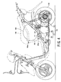
- One example of such scooter-type motorcycle is, for example, shown in Fig. 4.
- the scooter-type motorcycle is provided with a power unit 104, including an engine 101 and a power transmission 102, which is vertically swingable together with a rear wheel 103.
- a power unit 104 is disposed below an article accommodation box (or article storage chamber) 105.
- a cylinder 107 of the engine 101 extends forward from a front surface side of a crank case 106 of the engine 101 at a portion directly below the bottom surface 105a of the article accommodation box 105.
- a rider's seat 108 is disposed above the article accommodation box 105 to be openable about a rotational shaft 108a.
- reference numeral 109 denotes a helmet disposed in the accommodation box 105.
- the engine 101 is generally arranged below the rider's seat 108 in consideration of the structure of the motorcycle body, and therefore, a two-stroke-cycle engine is mainly mounted in an attitude as low as possible by almost horizontally laying the cylinder.
- a four-stroke-cycle engine has been mainly employed in view of environmental matters.
- an oil stored in a bottom portion of the crank case 106 is supplied to the cylinder (i.e., cylinder head) 107 by means of oil pump, and the oil circulation from the cylinder 107 to the crank case 106 is performed through dropping due to the gravity.
- the cylinder 107 has a front side portion extending obliquely upward in comparison with the arrangement in the two-stroke-cycle engine.
- the cylinder 107 extends forward from the front surface side of the crank case 106 at the portion directly below the bottom surface 105a of the article accommodation box 105, if the cylinder 107 is arranged with the front side portion thereof extending forward with an upward inclination in consideration of the well oil circulation, there may cause a fear that the cylinder 107 interferes with the bottom surface 105a of the accommodation box 105.
- the accommodation box 105 In order to obviate such fear, it will be necessary to arrange the accommodation box 105 so that the bottom surface 105a thereof is positioned at a higher level or to dispose both the accommodation box 105 and the rider's seat to be higher in its level in their entire structure, which adversely results in the reduction of the inner volume of the article accommodation box 105 or deterioration of the riding condition, footing condition or like of the motorcycle.
- crank case 106 there are disposed a swing shaft 111 being a center of pivotal movement of the power unit 104, a starter motor 112 for the engine operation, an intake device 113 of the engine and so on, and accordingly, it is necessary to consider the interference of these members with the bottom surface 105a of the article accommodation box 105. That is, it is obliged to pay attention to the arrangement of the members on the crank case 107 (i.e., the power unit 107) and the entire shape or size of the article accommodation box 105.
- the present invention was conceived in consideration of the above matters encountered in the prior art, and an object of the present invention is hence to provide a scooter-type motorcycle capable of ensuring a large inner volume of an article accommodation box and suppressing the rider's seat to be low even with an equipment of a four-stroke-cycle engine.
- the throttle body and the suction pipe are disposed in a manner offset from the longitudinal center line of the motorcycle body on one side in a width direction thereof the motorcycle body in its plan view, and the article accommodation box has a bottom surface portion having a rear side end which is circularly protruded at a central portion thereof.
- the article accommodation box preferably has an inner space in which a full-covered type (full-face cover type helmet) is accommodated with a top portion thereof directed upward and a front side portion directed rearward.
- the bottom surface of the article accommodation box has an inclination rearward downward in a side view of the motorcycle body.
- the engine cylinder extends forward slightly upward from a front surface portion of the crank case.
- a fuel tank may be disposed on a rear side of the article accommodation box and has an oiling port disposed below the rider's seat. In an alternation, the fuel tank may be disposed below a low-floor type step board provided for the body frame.
- the throttle body which has a vertical dimension larger than that of the intake manifold or suction pipe, is disposed in a recessed portion between the swing shaft and the starter motor, which are disposed on the front and rear sides of the crank case, respectively, so that the upward projection of the throttle body can be prevented to thereby make lower the entire structure of the power unit. Therefore, the bottom surface of the article accommodation box can be lowered in level, so that the inner volume thereof can be increased. Otherwise, the rider's seat may be lowered in level.
- the throttle body and the suction pipe are disposed in a manner offset on one side in a width direction of the motorcycle body, and the bottom surface portion has a rear side end which is circularly protruded at a central portion thereof, the interference of the suction pipe with the bottom surface of the article accommodation box can be prevented at a time when the power unit is rotated, and in addition, the inner volume of the accommodation box can be relatively increased.
- the full-covered type helmet can be accommodated with a top portion thereof directed upward and a front side portion, having a relatively small radius of curvature, directed rearward in the accommodation box in a manner, so that the rear side of the bottom surface of the accommodation box can be finely tapered, also preventing the interference of the suction pipe.
- the bottom surface of the accommodation box has an inclination rearward downward in a side view of the motorcycle body, so that the engine cylinder is disposed to be forward slightly upward, thus improving the oil circulation performance without interfering with the bottom surface.
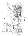
- FIG. 1 showing a left side view of the scooter-type motorcycle to which the present invention is applicable.
- the scooter-type motorcycle 1 is provided with a body frame 2 of low framework structure made of steel.
- the body frame 2 has a front head portion to which a front fork 4 and a handle bar 5, which support a front wheel 3, is journaled, and a power unit 7 is connected, at a central lower portion of the body frame 2, to a swing shaft 6 extending in the width direction thereof.
- the power unit 7 is of a standard structure as a scooter-type motorcycle provided with a four-stroke-cycle single-cylinder engine 9 and a power transmission (unit) 10, which are integrally assembled.
- the power transmission 10 is disposed on the left side portion, as viewed, of a crank case 11 of the engine 9, and a rear wheel 12 is journalled to the most rear right side portion of the power transmission 10.
- a speed-changing gear for changing the speed of the power, i.e., engine revolution
- a speed reduction unit for further reducing the engine power, which is then transmitted to the rear wheel 12.
- the engine 9 is accommodated with a cylinder 14 extending forward from the front surface of the crank case 11 in an attitude extending slightly obliquely forward in consideration of the oil circulation from the cylinder 14, i.e., cylinder head, to the crank case 11.
- the body frame 2 and the power unit 7 is coupled by means of swing shaft 6 at a position above the front portion of the crank case 11.
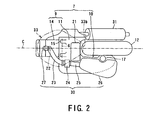
- a lateral pair of swing brackets 15 (see Fig. 2) formed on the upper surface of the crank case 11 so as to project therefrom are connected to the swing shaft 6.
- a rear cushion unit 17 is also arranged between the rear portion of the power transmission 10 and a cushion bracket 16 mounted to the rear portion of the body frame 2, and this rear cushion unit 17 serves as a shock absorber.
- the power unit 7 When the scooter-type motorcycle 1 runs, the power unit 7 is vertically swung about the swing shaft 6, together with the rear wheel 12, in accordance with the irregularity of the road on which the motorcycle runs, and this swing motion is buffered and decompressed through the shrinkage of the rear cushion unit 17.
- a starter motor 21 for starting the engine operation is disposed above the rear portion of the crank case 11 of the engine 9 with its axis being directed to the motorcycle body width direction.
- An intake port 22 opened to the upper surface of the cylinder 14 of the engine 9 is connected to a throttle body 24 by way of an intake manifold 23, and an air cleaner case 26 is also connected to the throttle body 24 through a suction pipe 25.
- An injector 27, as a fuel injection device, is disposed at a portion near the front end of the intake manifold 23.
- the air cleaner case 26, the suction pipe 25, the throttle body 24, the intake manifold 23 and the injector 27 constitute an intake device or unit 30.
- the throttle body 24 serves to adjust the intake air supply to the engine cylinder 14 in accordance with operation amount of a throttle grip, not shown, and the injector 27 injects the fuel to the suctioned air to thereby produce air-fuel mixture.
- An exhaust muffler 31 extends from the cylinder 14 of the engine 9 once downward and then rearward along the right side of the rear wheel 12.
- the exhaust muffler 31 and the intake device 30 are swung together with the power unit 7 and the rear wheel 12.
- a rider's seat 32 is provided above the rear half portion of the body frame 2, and an article accommodation box (or an article storage chamber) 33 having a bottomed box structure, is also provided below the rider's seat and above the power unit 7 (i.e., engine 9).
- the rider's seat 32 is openable upward about a rotational shaft 32a disposed at the front end side thereof, and this rider's seat 32 also contributes as a lid of the article accommodation box 33. That is, when the rider's seat is opened upward, the lid of the article accommodation box 33 is also opened.
- a fuel tank 34 is disposed on the rear side of the article accommodation box 33, and an oiling port 34a of the fuel tank 34 is also disposed below the rider's seat 32 and accessed by opening the same.
- the motorcycle body is covered substantially entirely by a body cover 36 made of resin to make fine an outer appearance of the scooter-type motorcycle 1 as well as to protect inner machineries thereof.
- a foot-rest floor (flat foot step) 37 is formed at a lower portion between the handle bar 5 and the rider's seat 32.
- the article accommodation box 33 has an inner volume or space capable of sufficiently storing a full-covered type helmet 39 in a state that the top portion of the helmet 39 is directed upward and the front side thereof is directed rearward in the box 33.
- the article accommodation box 33 has a flat bottom surface 33a with a slit rearward downward inclination so as to be almost parallel to the axial line 14a of the cylinder (also extending slightly in rearward downward direction) in the side view of the motorcycle body. Furthermore, the article accommodation box 33 is molded so that the rear end portion of the bottom surface 33a is protruded in a circular shape at its central portion as shown in Fig. 2. The article accommodation box 33 is positioned in the longitudinal direction of the motorcycle body so that the rear end portion of the helmet 39 accommodated therein is positioned near the upper portion of the front side end of the rear wheel 12.
- the air-cleaner case 26 constituting a part of the intake device 30 is positioned above the power transmission 10, and the air-cleaner case 26, the suction pipe 25, the throttle body 24 and the intake manifold 23 are arranged substantially horizontally from the rear side of the motorcycle body towards the front side thereof.
- the throttle body 24 is positioned between the swing shaft 6 disposed at the front upper portion of the crank case 11 and the starter motor 21 disposed at the rear upper portion of the crank case 11.
- the throttle body 24 and the suction pipe 25 are arranged, on the crank case 11, on the side, for example, left side as viewed, from the center line C of the motorcycle body in the plan view thereof.
- the intake port 22, to which the intake manifold 23 is connected, is, on the other hand, positioned above the center line C. According to such arrangement or layout, the intake manifold 23 once extends rearward obliquely in the left side and is then curved rearward and connected to the throttle body 24.
- the throttle body 24 of the intake device 30 is disposed in a deep portion between the swing shaft 6 and the starter motor 21 arranged at front and rear portions above the crank case 11, it becomes possible to prevent the throttle body 24, generally having a large vertical dimension in comparison with the intake manifold 23 and the suction pipe 25, from projecting largely upward over the swing shaft 6 and the starter motor 21.
- the suction pipe 25 which can be lowered in vertical attitude, and according to such arrangement, the entire height of the power unit can be lowered to thereby produce a sufficient clearance between the power unit 7 and the lower bottom surface 33a of the article accommodation box 33.
- the bottom surface 33a thereof in a lower level to thereby ensure the inner volume of the accommodation box 33, and moreover, since the vertical level of the rider's seat 32 can also be lowered, improving the riding condition, operability and footing fitness or comfortability of the scooter-type motorcycle 1.
- the suction pipe 25 displaced on one side of the motorcycle body is not overlapped, in the plan view of the motorcycle body, with the article accommodation box 33 molded, and the bottom surface portion protrudes rearward in a circular shape at its rear central portion. Accordingly, even in the upper rotational motion of the power unit 7, it hardly interferes with the bottom surface 33a of the article accommodation box 33.
- Fig. 1 showing the left side view of the scooter-type motorcycle 1 of the present invention
- the bottom surface 33a of the article accommodation box 33 is positioned directly above the suction pipe 25, as shown in Fig. 2, both the members 25 and 33 are not overlapped with each other, and hence, the suction pipe 25 does not interfere with the bottom surface 33a at the upper rotation of the power unit 7.
- the bottom surface 33a is set to be lower to thereby increase the inner storage volume or space of the accommodation box 33.
- the article accommodation box 33 is molded so as to provide the shape capable of accommodating the full-covered type helmet 39 such that the front side thereof is directed to the rearward in the accommodated state.
- the front side portion of the full-covered type helmet 39 has a radius of curvature smaller than that of the rear side portion thereof, the rear side portion of the accommodation box 33, in the plan view of the motorcycle body, can be molded to provide a sharp shape, which contributes to enlargement of the clearance among the article accommodation box 33, the suction pipe 25 and the throttle body 24.
- the bottom surface 33a of the article accommodation box 33 has the rearward downward inclination to be almost parallel to the axial line 14a of the engine cylinder 14, so that even if the cylinder has the forward upward inclination for the well oil circulation, the cylinder can be substantially free from the interference with the bottom surface 33a of the article accommodation box 33.
- Fig. 3 is a left side view of a scooter-type motorcycle 41 according to another embodiment of the present invention.
- This scooter-type motorcycle 41 has substantially the same members as those of the scooter-type motorcycle 1 of the first embodiment of Fig. 1 except for the following structure.
- the accommodation box 43 can be expanded in the rear direction.
- the expanded portion has a curved, i.e., inward staged, shape in conformity with the upper contour of the rear wheel 12 so that the rear portion of the bottom surface 43a of the accommodation box 43 does not interfere with the upper portion of the rear wheel 12.
- the front side portion of the accommodation box 43 has substantially the same shape as that of the motorcycle 1 of Fig. 1.
- the full-covered type helmet 39 can be accommodated without shifting it rearward in the accommodation box 43, and accordingly, another article can be additionally stored therein, thus being convenient.
Landscapes
- Engineering & Computer Science (AREA)
- Mechanical Engineering (AREA)
- Automatic Cycles, And Cycles In General (AREA)
Claims (7)
- Rollerartiges Motorrad (1; 41) mit einer Struktur, in der ein Gegenstandsaufnahmekasten (33; 43) mit einer oberen Öffnung unter dem Sitz (32) eines Fahrers angeordnet ist, der nach oben geöffnet werden kann, und eine Antriebseinheit (7) mit einem Motor und einer Kraftübertragung (10) unter dem Gegenstandsaufnahmekasten (33; 43) angeordnet ist, wobei der Motor ein Kurbelgehäuse (11) umfasst, von dem sich ein Zylinder (14) nach vorn erstreckt, wobei sich eine Schwenkwelle (6) der Antriebseinheit (7) in der Breitenrichtung der Antriebseinheit (7) erstreckt, so dass die Antriebseinheit (7) zusammen mit einem Hinterrad vertikal schwenkbar ist, ein Startermotor (21) zum Starten eines Betriebs des Motors (9) über einem hinteren Teil des Kurbelgehäuses (11) angeordnet ist, und eine Motoreinlassvorrichtung (30) mit einem Luftfilter (26), einem Saugrohr (25), einem Drosselkörper (24) und einem Einlasskrümmer (23), die im Wesentlichen horizontal von einem Rückseitenteil einer Motorradkarosserie in Richtung eines Vorderseitenteils davon angeordnet sind, mit dem Motor (9) verbunden ist, dadurch gekennzeichnet, dass die Schwenkwelle (6) über einem vorderen Teil des Kurbelgehäuses (11) angeordnet ist und dass der Drosselkörper (24) in einer Längsrichtung des rollerartigen Motorrads (1; 41) zwischen der Schwenkwelle (6) und dem Startermotor (21) angeordnet ist.
- Rollerartiges Motorrad nach Anspruch 1, wobei der Drosselkörper (24) und das Saugrohr (25) in einer Draufsicht in einer von einer Längsmittellinie der Motorradkarosserie auf einer Seite in einer Breitenrichtung davon versetzten Weise angeordnet sind und der Gegenstandsaufnahmekasten (33; 43) einen unteren Oberflächenteil (33a; 43a) mit einem Rückseitenende (33b) aufweist, das an einem Mittelteil davon kreisförmig nach außen vorsteht.
- Rollerartiges Motorrad (1; 41) nach Anspruch 1, wobei der Gegenstandsaufnahmekasten (33; 43) einen Innenraum aufweist, in dem ein Helm (39) vom vollständig abgedeckten Typ aufgenommen ist, wobei ein oberer Teil desselben nach oben gerichtet ist und ein Vorderseitenteil nach hinten gerichtet ist.
- Rollerartiges Motorrad (1; 41) nach Anspruch 1 bis 3, wobei der Gegenstandsaufnahmekasten (33; 43) eine untere Oberfläche (33a; 43a) mit einer Neigung nach hinten und nach unten in einer Seitenansicht der Motorradkarosserie aufweist.
- Rollerartiges Motorrad (1; 41) nach einem der Ansprüche 1 bis 4, wobei sich der Motorzylinder (14) von einem Vorderflächenteil des Kurbelgehäuse (11) geringfügig nach oben vorwärts erstreckt.
- Rollerartiges Motorrad (1; 41) nach einem der Ansprüche 1 bis 5, wobei ein Kraftstofftank (34; 42) auf einer Rückseite des Gegenstandsaufnahmekastens (33; 43) angeordnet ist und der Kraftstofftank (34; 42) eine Ölungsöffnung (34a) aufweist, die unter dem Sitz (32) des Fahrers angeordnet ist.
- Rollerartiges Motorrad (1; 41) nach einem der Ansprüche 1 bis 5, wobei ein Trittbrett (37) vom Niederflurtyp für den Karosserierahmen (2) vorgesehen ist und ein Kraftstofftank (34; 42) unter dem Trittbrett angeordnet ist.
Applications Claiming Priority (2)
| Application Number | Priority Date | Filing Date | Title |
|---|---|---|---|
| JP2003304691 | 2003-08-28 | ||
| JP2003304691A JP4453303B2 (ja) | 2003-08-28 | 2003-08-28 | スクーター型自動二輪車 |
Publications (3)
| Publication Number | Publication Date |
|---|---|
| EP1510450A2 EP1510450A2 (de) | 2005-03-02 |
| EP1510450A3 EP1510450A3 (de) | 2006-04-26 |
| EP1510450B1 true EP1510450B1 (de) | 2007-12-19 |
Family
ID=34101220
Family Applications (1)
| Application Number | Title | Priority Date | Filing Date |
|---|---|---|---|
| EP04019496A Expired - Lifetime EP1510450B1 (de) | 2003-08-28 | 2004-08-17 | Motorroller |
Country Status (5)
| Country | Link |
|---|---|
| US (1) | US6986400B2 (de) |
| EP (1) | EP1510450B1 (de) |
| JP (1) | JP4453303B2 (de) |
| CN (2) | CN2790890Y (de) |
| DE (1) | DE602004010752T2 (de) |
Families Citing this family (25)
| Publication number | Priority date | Publication date | Assignee | Title |
|---|---|---|---|---|
| JP4453303B2 (ja) * | 2003-08-28 | 2010-04-21 | スズキ株式会社 | スクーター型自動二輪車 |
| JP4259976B2 (ja) * | 2003-10-15 | 2009-04-30 | ヤマハ発動機株式会社 | 自動二輪車及び自動二輪車用エンジン |
| JP2006088892A (ja) * | 2004-09-24 | 2006-04-06 | Yamaha Motor Co Ltd | 鞍乗型車両 |
| ITTO20050666A1 (it) * | 2004-09-29 | 2006-03-30 | Honda Motor Co Ltd | Motociclo |
| US7434645B2 (en) * | 2004-11-12 | 2008-10-14 | Honda Motor Co., Ltd. | Swing arm structure in motorcycle |
| JP4430522B2 (ja) * | 2004-12-10 | 2010-03-10 | 本田技研工業株式会社 | 自動二輪車のスイングアーム支持構造 |
| JP4767603B2 (ja) * | 2005-07-04 | 2011-09-07 | ヤマハ発動機株式会社 | パワーユニット及び該パワーユニットを備えた鞍乗型車両 |
| JP5113358B2 (ja) * | 2005-10-07 | 2013-01-09 | ヤマハ発動機株式会社 | 鞍乗型車両 |
| JPWO2007148523A1 (ja) * | 2006-06-19 | 2009-11-19 | ヤマハ発動機株式会社 | 自動二輪車 |
| JP2008230535A (ja) * | 2007-03-23 | 2008-10-02 | Yamaha Motor Co Ltd | 自動二輪車 |
| JP5004006B2 (ja) * | 2007-04-04 | 2012-08-22 | 本田技研工業株式会社 | 自動二輪車用乗員シート |
| JP4995060B2 (ja) * | 2007-12-17 | 2012-08-08 | 本田技研工業株式会社 | 自動二輪車の排気装置 |
| JP5112844B2 (ja) * | 2007-12-26 | 2013-01-09 | 本田技研工業株式会社 | スクータ型車両 |
| JP5171554B2 (ja) * | 2008-10-31 | 2013-03-27 | 本田技研工業株式会社 | 自動二輪車 |
| JP5364524B2 (ja) * | 2009-09-30 | 2013-12-11 | 本田技研工業株式会社 | 自動二輪車 |
| JP5184503B2 (ja) * | 2009-12-24 | 2013-04-17 | 本田技研工業株式会社 | 鞍乗型車両 |
| JP5546878B2 (ja) * | 2010-01-19 | 2014-07-09 | 本田技研工業株式会社 | 鞍乗型車両 |
| JP5520623B2 (ja) * | 2010-01-29 | 2014-06-11 | 本田技研工業株式会社 | 燃料供給装置 |
| JP5498812B2 (ja) * | 2010-02-18 | 2014-05-21 | 本田技研工業株式会社 | 小型車両 |
| JP5694788B2 (ja) * | 2011-01-17 | 2015-04-01 | 本田技研工業株式会社 | 鞍乗型車両 |
| CN102996296B (zh) * | 2011-09-16 | 2015-07-01 | 雅马哈发动机株式会社 | 摩托车 |
| JP6056285B2 (ja) * | 2012-09-06 | 2017-01-11 | スズキ株式会社 | スクータ型車両 |
| JP6443108B2 (ja) * | 2015-02-16 | 2018-12-26 | スズキ株式会社 | ユニットスイング式エンジンユニット |
| US11305840B2 (en) * | 2017-11-02 | 2022-04-19 | Piaggio & C. S.P.A. | Electric drive motorcycle |
| US11420516B2 (en) * | 2018-12-03 | 2022-08-23 | Polaris Industries Inc. | Motorized vehicle |
Family Cites Families (13)
| Publication number | Priority date | Publication date | Assignee | Title |
|---|---|---|---|---|
| ES2157370T3 (es) * | 1995-06-29 | 2001-08-16 | Yamaha Motor Co Ltd | Transmision de variacion continua. |
| JPH09287486A (ja) * | 1996-04-23 | 1997-11-04 | Yamaha Motor Co Ltd | 輸送機器用エンジン |
| TW374747B (en) * | 1996-06-04 | 1999-11-21 | Suzuki Motor Corp | Motor scooter type vehicle |
| JP3765966B2 (ja) * | 1999-09-03 | 2006-04-12 | 本田技研工業株式会社 | 自動二・三輪車 |
| JP3836665B2 (ja) * | 2000-09-06 | 2006-10-25 | 本田技研工業株式会社 | 自動二輪車 |
| JP3949387B2 (ja) * | 2001-03-23 | 2007-07-25 | 本田技研工業株式会社 | 車両用開閉式リッド構造 |
| JP4132704B2 (ja) * | 2001-03-26 | 2008-08-13 | 本田技研工業株式会社 | スクータ型車両のシート取付構造 |
| JP4108290B2 (ja) * | 2001-03-28 | 2008-06-25 | 本田技研工業株式会社 | 車両の後部構造 |
| JP4077173B2 (ja) * | 2001-05-11 | 2008-04-16 | 本田技研工業株式会社 | スクータ型車両 |
| TW561262B (en) * | 2001-10-19 | 2003-11-11 | Yamaha Motor Co Ltd | Tipping detecting device for a motorcycle |
| JP3899006B2 (ja) * | 2001-12-14 | 2007-03-28 | ヤマハ発動機株式会社 | スクータ型自動二輪車の車体フレーム |
| JP2003182667A (ja) * | 2001-12-14 | 2003-07-03 | Yamaha Motor Co Ltd | 鞍乗型車両における物入れ装置 |
| JP4453303B2 (ja) * | 2003-08-28 | 2010-04-21 | スズキ株式会社 | スクーター型自動二輪車 |
-
2003
- 2003-08-28 JP JP2003304691A patent/JP4453303B2/ja not_active Expired - Fee Related
-
2004
- 2004-08-17 EP EP04019496A patent/EP1510450B1/de not_active Expired - Lifetime
- 2004-08-17 US US10/919,395 patent/US6986400B2/en not_active Expired - Lifetime
- 2004-08-17 DE DE602004010752T patent/DE602004010752T2/de not_active Expired - Lifetime
- 2004-08-30 CN CNU2004200771881U patent/CN2790890Y/zh not_active Expired - Lifetime
- 2004-08-30 CN CNB200410074870XA patent/CN100371206C/zh not_active Expired - Fee Related
Also Published As
| Publication number | Publication date |
|---|---|
| CN1590205A (zh) | 2005-03-09 |
| CN2790890Y (zh) | 2006-06-28 |
| JP2005075030A (ja) | 2005-03-24 |
| CN100371206C (zh) | 2008-02-27 |
| DE602004010752D1 (de) | 2008-01-31 |
| US6986400B2 (en) | 2006-01-17 |
| US20050045400A1 (en) | 2005-03-03 |
| EP1510450A2 (de) | 2005-03-02 |
| JP4453303B2 (ja) | 2010-04-21 |
| EP1510450A3 (de) | 2006-04-26 |
| DE602004010752T2 (de) | 2008-12-11 |
Similar Documents
| Publication | Publication Date | Title |
|---|---|---|
| US6986400B2 (en) | Scooter-type motorcycle | |
| KR100370671B1 (ko) | 스쿠터형 자동 이륜차 | |
| JP3154660U (ja) | 自動二輪車 | |
| EP1304283B1 (de) | Rollerartiges Motorrad | |
| CN102791969B (zh) | 用于摩托车的引擎的通气装置 | |
| JP2011031872A (ja) | 自動二輪車 | |
| JP2006130975A (ja) | スクーター型自動二輪車 | |
| JP3267530B2 (ja) | スクータ型車両 | |
| JP4280361B2 (ja) | 自動二輪車におけるエアクリーナの吸気構造 | |
| JP4303361B2 (ja) | スクータ型車両 | |
| JP2012076554A (ja) | スクータ型自動二輪車におけるキャニスタの配置構造 | |
| JP3390464B2 (ja) | 自動二輪車における車両構成部品の配設構造 | |
| EP1319591B1 (de) | Im Grätschsitz zu benutzendes Fahrzeug | |
| JP4015418B2 (ja) | スクータ型自動二輪車 | |
| JP2006096203A (ja) | 自動二輪車の車体構造 | |
| JP2014069715A (ja) | 自動二輪車用吸気装置 | |
| JP2011031873A (ja) | 自動二輪車 | |
| JP2010221988A (ja) | 自動二輪車 | |
| JP2528623B2 (ja) | 4サイクルエンジンを搭載したスク―タ型自動二輪車 | |
| EP1759974B1 (de) | Motorrad | |
| JP2009226989A (ja) | 自動二輪車の燃料配管構造 | |
| JP4421696B2 (ja) | 自動二輪車 | |
| JP3261341B2 (ja) | スクータ型車両 | |
| JP3270362B2 (ja) | スクータ型車両 | |
| JP3168136U (ja) | スクータ型車両の吸気装置 |
Legal Events
| Date | Code | Title | Description |
|---|---|---|---|
| PUAI | Public reference made under article 153(3) epc to a published international application that has entered the european phase |
Free format text: ORIGINAL CODE: 0009012 |
|
| 17P | Request for examination filed |
Effective date: 20040817 |
|
| AK | Designated contracting states |
Kind code of ref document: A2 Designated state(s): AT BE BG CH CY CZ DE DK EE ES FI FR GB GR HU IE IT LI LU MC NL PL PT RO SE SI SK TR |
|
| AX | Request for extension of the european patent |
Extension state: AL HR LT LV MK |
|
| PUAL | Search report despatched |
Free format text: ORIGINAL CODE: 0009013 |
|
| AK | Designated contracting states |
Kind code of ref document: A3 Designated state(s): AT BE BG CH CY CZ DE DK EE ES FI FR GB GR HU IE IT LI LU MC NL PL PT RO SE SI SK TR |
|
| AX | Request for extension of the european patent |
Extension state: AL HR LT LV MK |
|
| AKX | Designation fees paid |
Designated state(s): DE FR IT |
|
| 17Q | First examination report despatched |
Effective date: 20070125 |
|
| GRAP | Despatch of communication of intention to grant a patent |
Free format text: ORIGINAL CODE: EPIDOSNIGR1 |
|
| GRAS | Grant fee paid |
Free format text: ORIGINAL CODE: EPIDOSNIGR3 |
|
| GRAA | (expected) grant |
Free format text: ORIGINAL CODE: 0009210 |
|
| AK | Designated contracting states |
Kind code of ref document: B1 Designated state(s): DE FR IT |
|
| REF | Corresponds to: |
Ref document number: 602004010752 Country of ref document: DE Date of ref document: 20080131 Kind code of ref document: P |
|
| ET | Fr: translation filed | ||
| PLBE | No opposition filed within time limit |
Free format text: ORIGINAL CODE: 0009261 |
|
| STAA | Information on the status of an ep patent application or granted ep patent |
Free format text: STATUS: NO OPPOSITION FILED WITHIN TIME LIMIT |
|
| 26N | No opposition filed |
Effective date: 20080922 |
|
| REG | Reference to a national code |
Ref country code: FR Ref legal event code: PLFP Year of fee payment: 13 |
|
| REG | Reference to a national code |
Ref country code: FR Ref legal event code: PLFP Year of fee payment: 14 |
|
| REG | Reference to a national code |
Ref country code: DE Ref legal event code: R082 Ref document number: 602004010752 Country of ref document: DE Representative=s name: KLUNKER IP PATENTANWAELTE PARTG MBB, DE |
|
| REG | Reference to a national code |
Ref country code: FR Ref legal event code: PLFP Year of fee payment: 15 |
|
| PGFP | Annual fee paid to national office [announced via postgrant information from national office to epo] |
Ref country code: FR Payment date: 20190711 Year of fee payment: 16 Ref country code: DE Payment date: 20190806 Year of fee payment: 16 Ref country code: IT Payment date: 20190821 Year of fee payment: 16 |
|
| REG | Reference to a national code |
Ref country code: DE Ref legal event code: R119 Ref document number: 602004010752 Country of ref document: DE |
|
| PG25 | Lapsed in a contracting state [announced via postgrant information from national office to epo] |
Ref country code: DE Free format text: LAPSE BECAUSE OF NON-PAYMENT OF DUE FEES Effective date: 20210302 Ref country code: FR Free format text: LAPSE BECAUSE OF NON-PAYMENT OF DUE FEES Effective date: 20200831 |
|
| PG25 | Lapsed in a contracting state [announced via postgrant information from national office to epo] |
Ref country code: IT Free format text: LAPSE BECAUSE OF NON-PAYMENT OF DUE FEES Effective date: 20200817 |