EP1213711B1 - Device and method for controlling tilt servo - Google Patents
Device and method for controlling tilt servo Download PDFInfo
- Publication number
- EP1213711B1 EP1213711B1 EP01127444A EP01127444A EP1213711B1 EP 1213711 B1 EP1213711 B1 EP 1213711B1 EP 01127444 A EP01127444 A EP 01127444A EP 01127444 A EP01127444 A EP 01127444A EP 1213711 B1 EP1213711 B1 EP 1213711B1
- Authority
- EP
- European Patent Office
- Prior art keywords
- recording medium
- tilt
- dvd
- signal
- optical recording
- Prior art date
- Legal status (The legal status is an assumption and is not a legal conclusion. Google has not performed a legal analysis and makes no representation as to the accuracy of the status listed.)
- Expired - Lifetime
Links
Images


Classifications
-
- G—PHYSICS
- G11—INFORMATION STORAGE
- G11B—INFORMATION STORAGE BASED ON RELATIVE MOVEMENT BETWEEN RECORD CARRIER AND TRANSDUCER
- G11B7/00—Recording or reproducing by optical means, e.g. recording using a thermal beam of optical radiation by modifying optical properties or the physical structure, reproducing using an optical beam at lower power by sensing optical properties; Record carriers therefor
- G11B7/08—Disposition or mounting of heads or light sources relatively to record carriers
- G11B7/09—Disposition or mounting of heads or light sources relatively to record carriers with provision for moving the light beam or focus plane for the purpose of maintaining alignment of the light beam relative to the record carrier during transducing operation, e.g. to compensate for surface irregularities of the latter or for track following
- G11B7/095—Disposition or mounting of heads or light sources relatively to record carriers with provision for moving the light beam or focus plane for the purpose of maintaining alignment of the light beam relative to the record carrier during transducing operation, e.g. to compensate for surface irregularities of the latter or for track following specially adapted for discs, e.g. for compensation of eccentricity or wobble
- G11B7/0956—Disposition or mounting of heads or light sources relatively to record carriers with provision for moving the light beam or focus plane for the purpose of maintaining alignment of the light beam relative to the record carrier during transducing operation, e.g. to compensate for surface irregularities of the latter or for track following specially adapted for discs, e.g. for compensation of eccentricity or wobble to compensate for tilt, skew, warp or inclination of the disc, i.e. maintain the optical axis at right angles to the disc
-
- G—PHYSICS
- G11—INFORMATION STORAGE
- G11B—INFORMATION STORAGE BASED ON RELATIVE MOVEMENT BETWEEN RECORD CARRIER AND TRANSDUCER
- G11B7/00—Recording or reproducing by optical means, e.g. recording using a thermal beam of optical radiation by modifying optical properties or the physical structure, reproducing using an optical beam at lower power by sensing optical properties; Record carriers therefor
- G11B7/12—Heads, e.g. forming of the optical beam spot or modulation of the optical beam
- G11B7/135—Means for guiding the beam from the source to the record carrier or from the record carrier to the detector
- G11B7/1365—Separate or integrated refractive elements, e.g. wave plates
- G11B7/1369—Active plates, e.g. liquid crystal panels or electrostrictive elements
-
- G—PHYSICS
- G11—INFORMATION STORAGE
- G11B—INFORMATION STORAGE BASED ON RELATIVE MOVEMENT BETWEEN RECORD CARRIER AND TRANSDUCER
- G11B7/00—Recording or reproducing by optical means, e.g. recording using a thermal beam of optical radiation by modifying optical properties or the physical structure, reproducing using an optical beam at lower power by sensing optical properties; Record carriers therefor
- G11B2007/0003—Recording, reproducing or erasing systems characterised by the structure or type of the carrier
- G11B2007/0006—Recording, reproducing or erasing systems characterised by the structure or type of the carrier adapted for scanning different types of carrier, e.g. CD & DVD
-
- G—PHYSICS
- G11—INFORMATION STORAGE
- G11B—INFORMATION STORAGE BASED ON RELATIVE MOVEMENT BETWEEN RECORD CARRIER AND TRANSDUCER
- G11B7/00—Recording or reproducing by optical means, e.g. recording using a thermal beam of optical radiation by modifying optical properties or the physical structure, reproducing using an optical beam at lower power by sensing optical properties; Record carriers therefor
- G11B7/08—Disposition or mounting of heads or light sources relatively to record carriers
- G11B7/09—Disposition or mounting of heads or light sources relatively to record carriers with provision for moving the light beam or focus plane for the purpose of maintaining alignment of the light beam relative to the record carrier during transducing operation, e.g. to compensate for surface irregularities of the latter or for track following
- G11B7/0945—Methods for initialising servos, start-up sequences
Definitions
- the present invention relates to a tilt servo control device according to the preamble of claims 1 and 22 and a tilt servo control method according to the preamble of claims 21 and 24.
- information reproducing apparatus for reproducing information recorded on an optical disk are normally provided with a tilt servo control device for detecting the tilt between a pickup as information reading means of the apparatus and the optical disk and compensate the tilt by adjusting the direction of the pickup in accordance with the detected tilt or by providing a signal read out by the pickup with a tilt correcting process corresponding to the detected tilt, so as to suppress the deterioration in the information reading accuracy.
- a tilt servo control device provided with a liquid crystal panel inserted into the optical axis is known (For example, Japanese Patent Laid-Open Publication No. Hei. 11-3531 or US-A- 5 886 496).
- the liquid crystal panel is divided into a plurality of regions, and a phase difference is provided to a light beam passing through each of the regions of the liquid crystal panel so as to maximize the level of a signal (RF signal) read out from a recording medium by a pickup.
- optical disks not only read only optical disks such as a CD-ROM and a DVD-ROM but also writable type optical disks such as a DVD-R, a DVD-RW and a DVD-RAM are included. It is desired that a single optical recording/playing apparatus can correspond to optical disks of any types for the purpose of recording and/or reproducing information. Therefore, it is necessary to mount a tilt servo control device that can properly perform tilt servo control for optical recording media of various different types in the optical recording/playing apparatus.
- US-A- 6 141 304 discloses a device according to the preamble of claim 1 and a method according to the preamble of claim 21.
- the present invention provides a tilt servo control device of an information recording/reproducing apparatus for recording information on and reproducing information from an optical recording medium set into the apparatus, the apparatus comprising an optical system for leading a laser beam emitted from a light source to a recording surface of the optical recording medium and a laser beam reflected by the recording surface of the recording medium to a photo detector and read signal generating means for generating a read signal in accordance with an output signal of the photo detector.
- the device comprises recording medium type determining means for determining a type of the optical recording medium, tilt drive signal generating means for generating a tilt drive signal so as to reduce a tilt angle between a normal to the recording surface of the optical recording medium at a position of the laser beam irradiating the recording surface and an optical axis of the laser beam by a method for generating a tilt drive signal corresponding to the type determined by the recording medium type determining means, tilt angle adjusting means for adjusting the tilt angle, and drive means for driving the tilt angle adjusting means in accordance with the tilt drive signal.
- the present invention provides a tilt servo control method of an information recording/reproducing apparatus for recording information on and reproducing information from an optical recording medium set into the apparatus, the apparatus comprising an optical system for leading a laser beam emitted from a light source to a recording surface of the optical recording medium and a laser beam reflected by the recording surface of the recording medium to a photo detector and read signal generating means for generating a read signal in accordance with an output signal of the photo detector.
- the method comprises the steps of determining a type of the optical recording medium, generating a tilt drive signal so as to reduce a tilt angle between a normal to the recording surface of the optical recording medium at a position of the laser beam irradiating the recording surface and an optical axis of the laser beam by a method for generating a tilt drive signal corresponding to the recording medium type, and driving tilt angle adjusting means for adjusting the tilt angle in accordance with the tilt drive signal.
- This method serves for compensating the tilt angle of a recording surface of an optical recording medium as defined by the angle between the normal to the recording surface of the recording medium and the optical axis of a light beam irradiating the recording surface
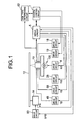
- Fig. 1 is a block diagram of a disk player provided with a tilt servo control device according to the present invention.
- Fig. 2 is a schematic diagram illustrating the recording format of a DVD-RW.
- Fig. 3 is a schematic diagram illustrating the recording format of a general purpose DVD-R.
- Fig. 4 is a diagram illustrating a physical structure of a recording surface of a DVD-RW or DVD-R.
- Fig. 5 is a graph illustrating the waveform of a groove wobble signal including LLP components.
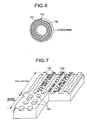
- Fig. 6 is a schematic diagram illustrating recording tracks of a DVD-RAM.
- Fig. 7 is an enlarged view of a recording surface of the DVD-RAM of Fig. 6.
- Fig. 8 is a schematic diagram illustrating the recording format of the header section of each sector located at a changeover point of the DVD-RAM of Fig. 6.
- Fig. 9 is a schematic diagram illustrating the recording format of the header section of each sector without a changeover point of the DVD-RAM of Fig. 6.
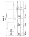
- Fig. 10 is a schematic diagram illustrating VFO data of a header section and a data section.
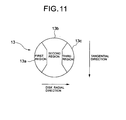
- Fig. 11 is a schematic diagram illustrating different regions of a liquid crystal panel arranged in a pickup of Fig. 1.
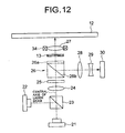
- Fig. 12 is a structural diagram schematically illustrating the optical system of the pickup of Fig. 1.
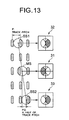
- Fig. 13 is a schematic diagram illustrating beam spots formed on an optical disk.
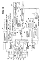
- Fig. 14 is a schematic block diagram illustrating a circuit including a pickup, a tracking servo circuit and a tilt servo circuit.
- Fig. 15 is a schematic block diagram of a focusing servo circuit and a spindle servo circuit.
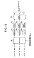
- Fig. 16 is a schematic block diagram of a tilt servo drive system.
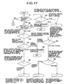
- Fig. 17 is a flow chart illustrating the operation of a disk type discriminating circuit.
- Fig. 18 is the remaining portion of the flow chart of Fig. 17.
- Fig. 19 is a graph illustrating the S-characteristics of a CD type disk and a DVD type disk.
- Fig. 20 is a flow chart of the tilt servo control operation of a first tilt servo section for a general purpose DVD-R or a DVD-RW.
- Fig. 21 is a flow chart of a tilt servo control operation of the first tilt servo section for an authoring purpose DVD-R.
- Fig. 22 is a flow chart of an alternative tilt servo control operation of the first tilt servo section for an authoring purpose DVD-R.
- Fig. 1 is a schematic block diagram of an optical disk player provided with a tilt servo control device according to the present invention.
- a pickup 10 irradiates a laser beam onto an optical disk 12 and receives a laser beam reflected by the optical disk 12. Then, the pickup 10 generates a signal corresponding to the intensity of the received laser beam.
- the optical disk 12 is driven to rotate by a motor 14.
- the optical disk 12 may be a DVD type disk such as a DVD-ROM, a DVD-R, a DVD-RAM and a DVD-RW or a CD type disk such as a CD-ROM and a CD-R.
- the DVD-RAM has two types, a one-recording-layer disk and a two-recording-layer disk.
- a DVD-RW has data structure including a PCA (power calibration area), an RMA (recording management area), a lead-in area, a data area and a lead-out area arranged in the mentioned order from the inner periphery to the outer periphery of the disk.
- the PCA is an area to be used for a test writing operation so as to determine a recording power level of the laser beam and the RMA is an area where management information on the current recording operation is written.
- the lead-in area contains an embossed section comprising phase pits formed on the disk in advance. The embossed section stores information on prohibition of copying.
- a DVD-R may be a general purpose disk or an authoring purpose disk.
- a general purpose DVD-R has a data structure including a PCA, an RMA, a lead-in area, a data area and a lead-out area arranged in the mentioned order from the inner periphery to the outer periphery of the disk.
- the lead-in area contains in part thereof a pre-write section that is located at a position exactly corresponding to that of the embossed section and used to store information just like the embossed section.
- an authoring purpose DVD-R does not have any section that corresponds to the embossed section in Fig. 2 or the pre-write section in Fig. 3.
- Fig. 4 is a schematic perspective partial view of the recording surface of DVD-RW or DVD-R, illustrating its physical structure.
- the recording surface is realized by combining a groove wobble system of wobbled grooves 103, formed between lands 102 on a disk substrate 103, operating as recording tracks and land pre-pits (LPPs) 104 formed in the lands 102 to link adjacent grooves 103.
- LPPs land pre-pits
- Information is recorded only in grooves 103.
- the recording surface is covered by a protection layer 105 typically made of polycarbonate.
- the signals obtained by the groove wobble system are mainly used to control the rotation motion of the disk during a recording operation and generate recording master clock for recording operations, whereas the LPPs are used for determining the recording position accurately on a bit by bit basis and also for obtaining various pieces of information on the disk such as pre-addresses.
- the low frequency zone component of the output signal (push-pull signal) of multiplier 44 is the signal that is obtained by the groove wobble system (groove wobble signal), showing a sinusoidal waveform as illustrated in Fig. 5.
- the narrow width pulses produced in parts of the sinusoidal waveform correspond to LPP components that can be detected by comparing the level of the signal with a threshold value TH.
- Fig. 7 is an enlarged schematic perspective partial view of the recording surface of the DVD-RAM of Fig. 6.
- the tracks are wobbled as shown in Fig. 7.
- Lands 131 and grooves 132 are arranged alternately for the tracks. Changeover points 133 from the lands 131 to the respective grooves 132 are located on a same radial line.
- Data are recorded on the tracks on a sector by sector basis.
- a sector provides a unit for recording data.
- Each sector comprises a header section and a data section.
- the header section comprises physically embossed pits 134 that are displaced from the center line of the track and located near the boundary with the adjacent track.
- the data section stores data in the form of phase change pits that are formed by producing changes in the reflectance in the respective areas of the surface of the disk hit by a laser beam. More specifically, the changes are produced as a result of phase changes.
- the level of the signal read from the disk will be affected by the recording principle and the recording conditions of the signal.
- Fig. 8 is a schematic illustration of the recording format of the header section of a sector located at a changeover point 133.
- Fig. 9 is a schematic illustration of the header section of a sector not related to any changeover point.
- the both sectors comprise a header section having four header fields, a mirror surface section located immediately after the header section and a data section having a land or groove structure as described above.
- An embossed pit is formed in each of the header fields although not shown in Figs. 8 and 9.
- the leading two header fields, or the first and second header fields, of the four header fields of each land sector are displaced radially inwardly from the center line of the track (by a half of the track pitch), whereas the remaining two header fields, or the third and fourth header fields, of the land sector are displaced radially outwardly from the center line of the track (by a half of the track pitch).
- the four header fields of each groove sector are mirror images of the header fields of the corresponding land sector.
- VFO variable frequency oscillator
- the VFO data of each VFO shows a predetermined data pattern of repeated "0s" and "1s" for every 4T (T representing the bit interval of successive information data).
- a VFO is arranged at the leading end of each of the first through fourth header fields of the header section in each sector.
- First VFO data of the first field and the third field have a length equal to 576 clocks
- second VFO data of the second field and the fourth field have a length equal to 128 clocks.
- a VFO data having a length equal to 560 clocks is arranged in the data section. For instance, a DVD-RAM contains these VFO data as part of fixed data without fail.
- a liquid crystal panel 13 is arranged on the optical axis of the beam of light in the pickup 10 for the purpose of correcting aberrations in radial directions of the disk in order to make it possible to correct the wave front aberrations of the optical system.
- the liquid crystal panel 13 is typically divided into three regions 13a through 13c along a radial direction as shown in Fig. 11. These regions include an inner peripheral side region, an intermediary region and an outer peripheral side region.
- the three regions 13a through 13c are individually and variably controlled by the respective drive voltages output from a tilt servo circuit 51 by way of a drive circuit 28 as will be described hereinafter. With this arrangement, the phase difference of light passing through each of the regions 13a through 13c can be changed individually so that the wave front aberrations such as coma that are produced by a tilt of the disk in a radial direction thereof may be corrected.
- the optical system of the pickup 10 comprises a semiconductor laser element 21 for emitting a laser beam with a wavelength of 650nm for DVDs and a semiconductor laser element 22 for emitting a laser beam with a wavelength of 780nm for CDs.
- the semiconductor laser elements 21, 22 are arranged in such a way that the center lines of the laser beams emitted from them are perpendicular relative to each other.
- a conflux prism 23 is arranged across the laser beams emitted from the semiconductor laser elements 21, 22 so that the laser beam emitted from the semiconductor laser element 21 is transmitted through the conflux prism 23 whereas the laser beam emitted from the semiconductor laser element 22 is reflected by the conflux prism 23 and made to leave the latter in a direction same as that of the laser beam emitted from the semiconductor laser 21.
- the semiconductor laser element 21 is driven by a drive circuit 18 whereas the semiconductor laser element 22 is driven by another drive circuit 19.
- the laser beams coming from the conflux prism 23 are made to get to a polarization beam splitter 26 provided with a polarizer panel 26a by way of a collimator lens 24 and a grating 25.
- the grating 25 is arranged to divide the laser beams into a plurality of fluxes (flux of 0 order, those of ⁇ 1 order). In other words, a main beam and a pair of sub beams are formed by it.
- the polarization beam splitter 26 allows most (e. g., 90%) of the laser beam entering it to pass through it and the polarizer panel 26a transforms the linear polarization of the passing laser beam into circular polarization.
- the laser beam that is allowed to pass through the polarization beam splitter 26 having the polarizer panel 26a then gets to the disk 12 by way of the liquid crystal panel 13 and the objective lens 27 thereof and becomes reflected by the recording surface of the disk 12.
- the laser beam reflected by the recording surface of the disk 12 then returns to the polarization beam splitter 26 by way of the liquid crystal panel 13 and the polarizer panel 26a.
- the polarizer panel 26a transforms the circular polarization of the reflected and returned laser beam into linear polarization.
- the polarization beam splitter 26 reflects the returned laser beam by means of its polarizing/splitting plane 26b.
- the reflected laser beam then gets to the light receiving plane of photo detector 30 by way of condenser lens 28 and multi lens 29.
- the pickup 10 further comprises an actuator 34 having a focusing section for moving the objective lens 27 along the optical axis and a tracking section for moving the objective lens 27 in a radial direction of the disk that is perpendicular to the optical axis.
- spots MS, SS1, SS2 are formed on the disk 12 by the main beam and the sub beams of the laser beam coming from the pickup 10. Note that the two sub beam spots SS1, SS2 are displaced from the main beam spot MS in a radial direction of the disk by a half of the track pitch P. This is because the differential push-pull method is used for detecting tracking errors.
- the photo detector 30 comprises a light receiving section 31 for receiving a main beam and a pair of light receiving sections 32, 33 for receiving sub beams arranged at opposite sides of the light receiving section 31.
- the light receiving surface of the light receiving section 31 is divided into four areas to produce photo detecting elements 31a through 31d, whereas the light receiving surfaces of the light receiving sections 32, 33 are divided into two areas to produce photo detecting elements 32a, 32b and 33a, 33b.
- the pickup 10 comprises an adder 35 for adding the output signal a of the photo detecting element 31a and the output signal c of the photo detecting element 31c, another adder 36 for adding the output signal b of the photo detecting element 31b and the output signal d of the photo detecting element 31d and still another adder 37 for outputting an RF signal (read signal) by adding the output signals of the adders 35, 36.
- the output of the adder 37 is connected to the tilt servo circuit 51 and the disk type discriminating circuit 52 of a servo circuit 5 as well as to a reproduction processing section (not shown).
- the outputs of the adders 35, 36 are connected to a focusing servo circuit 53.
- the focusing servo circuit 53 comprises an amplifier 61 for amplifying the output signal of the adder 35, another amplifier 62 for amplifying the output signal of the adder 36, a subtracter 63 for generating a focus error signal FE by subtracting the output signal of the amplifier 62 from the output signal of the amplifier 61, an equalizer 64 for generating a focus drive signal FD in accordance with the focus error signal FE that is the output signal of the subtracter 63, a switch 65, still another adder 66 and a voltage application circuit 67 for generating a variable voltage.
- the focus drive signal FD output from the equalizer 64 is fed to drive circuit 68 by way of the switch 65 and the adder 66 when the switch 65 is on.
- the drive circuit 68 drives the focusing section of the actuator 34 in accordance with the focus drive signal FD.
- the on/off operations of the switch 65 are controlled by the system control circuit 1.
- the voltage application circuit 67 generates a variable voltage in accordance with the focus jump command from the system control circuit 6. As a variable voltage is generated by the voltage application circuit 67, it is added by the adder 66 and the output signal of the adder 66 become the focus drive signal FD.
- the pickup 10 additionally comprises an adder 38 for adding the output signal a of the photo detecting element 31a and the output signal d of the photo detecting element 31d, another adder 39 for adding the output signal b of the photo detecting element 31b and the output signal c of the photo detecting element 31c and a subtracter 40 for subtracting the output signal of the adder 39 from that of the adder 38.
- the output of the subtracter 40 is connected to the disk type discriminating circuit 52 and the tracking servo circuit 54 of the servo circuit 5.
- the output signal of the subtracter 40 is a push-pull signal.
- the pickup 10 further comprises a subtracter 41 for subtracting the output signal of the photo detecting element 32b from the output signal of the photo detecting element 32a and another subtracter 42 for subtracting the output signal of the photo detecting element 33b from the output signal of the photo detecting element 33a.
- the outputs of the subtracters 41, 42 are connected to the tracking servo circuit 54.
- the tracking servo circuit 54 comprises an adder for adding the output signals of the subtracters 41, 42, a multiplier 44 for multiplying the output signal of the adder 43 by a coefficient a, a subtracter 45 for generating a differential push-pull tracking error signal TE by subtracting the output signal of the multiplier 44 from the output signal (push-pull signal) of the subtracter 40, an equalizer 46 for generating a tracking drive signal TD in accordance with the tracking error signal TE output from the subtracter 45 and a switch 47.
- the coefficient ⁇ of the adder 44 is determined in such a way that the output signal (push-pull of the main beam) of the subtracter 40 and the output signal (push-pull of the sub beams) of the multiplier 44 are made substantially equal to each other. Note that these two output signals have respective AC components whose polarities are opposite to each other and respective DC components that show a same polarity.
- the equalizer 46 generates the tracking drive signal TD so as to reduce the tracking error signal TE.
- the tracking drive signal TD output from the equalizer 46 is fed to the drive circuit 48 by way of the switch 47 when the switch 47 is on.
- the drive circuit 48 drives the tracking section of the actuator 34 in accordance with the tracking drive signal TD.
- the on/off operations of the switch 47 are controlled by the system control circuit 1.
- the tilt servo circuit 51 generates a tilt drive signal TID for driving the above described liquid crystal panel 13 and is provided with three tilt servo sections, or the first through third tilt servo sections, that are adapted to selectively operate depending on the type of the disk 12.
- the first tilt servo section is used for DVD-Rs and DVD-RWs and, as shown in Fig. 14, comprises an adder 69, a low pass filter 73, a changeover switch 70, a reference memory 71, a subtracter 72, an A/D converter 74 and a tilt correction ROM 75.
- the adder 69 adds the output signal of the subtracter 40 in the pickup 10 and that of the multiplier 44 in the tracking servo circuit 54.
- the push-pull component of the output of the adder 69 is cancelled to leave only the DC component.
- the output signal of the adder 69 is smoothed as it is input to the low pass filter 73 so that the eccentric component of the disk will be removed.
- the output signal of the low pass filter 73 is supplied to the reference memory 71 by way of the changeover switch 70 to represents a state involving no tilt before an information recording operation and the reference memory 71 stores the supplied signal level as reference signal.
- the changeover switch 70 relays the output signal of the low pass filter 73 to the subtracter 72 during a recording operation.
- the output signal of the low pass filter 73 is a push-pull signal containing an offset component that varies as a function of the tilt of the disk 12, or a push-pull offset signal.
- the subtracter 72 generates a first tilt error signal representing the tilt of the disk 12 by subtracting the reference signal stored in the reference memory 71 from the output signal of the adder 69.
- the output signal of the multiplier 44 and that of the subtracter 40 are tracking error signals containing an offset component that represents the tilt of the disk 12.
- the signal obtained by removing the offset component from the signal produced as the sum of the two signals by means of the adder 69 is stored in the reference memory 71 as reference signal.
- the signal output from the subtracter 72 as a result of subtracting the reference signal from the output signal of the adder 69 contains only the offset component so that it is possible to provide the first tilt error signal.
- the first tilt error signal is digitized by the A/D converter 74 and then fed to the tilt correction ROM 75, which stores a plurality of tilt correction values and output three correction values stored at the respective addresses specified by the first tilt error signal. These three correction values correspond respectively to the three regions 13a through 13c of the liquid crystal panel 13.
- the low pass filter 73 is provided in this embodiment, it may be omitted and the first tilt error signal may be obtained directly from the subtracter 72 when the eccentric component of the disk is small.
- the output signal of the subtracter 40 and that of the multiplier 44 are added by the adder 70 in this embodiment, it may alternatively be so arranged that only either the output signal (main push-pull signal) of the subtracter 40 or the output signal (sub push-pull signal) of the multiplier 44 is smoothed by the low pass filter and fed to the reference memory 71 by way of the changeover switch 70.
- the second tilt servo section that is used for DVD-RAMs comprises a delay circuit 76, a subtracter 77, a low pass filter 78, an A/D converter 79 and a tilt correction ROM 80.
- the delay circuit 76 delays the RF signal output form the adder 37 and supplies it to the subtracter 77.
- the RF signal corresponds to the first VFO data (of 64 bytes) in the first and third header fields of the above described header format of DVD-RAM.
- the delay time of the delay circuit 76 corresponds to the time necessary for passing through the first header field and the second header filed of the header section.
- the first VFO data of the first header field is fed from the delay circuit 76 to one of the input terminals (non-inversion input terminal) of the subtracter 77
- the first VFO data of the third header field is fed to the other input terminal (inversion input terminal) of the subtracter 77.
- the subtracter 77 subtracts the first VFO data of the third head field from the first VFO data of the first header field and supplies a signal representing the different to the low pass filter 78.
- the low pass filter 78 smooths the signal obtained by the subtraction and generates a second tilt error signal.
- the second tilt error signal is digitized by the A/D converter 79 and then fed to the tilt correction ROM 80, which stores a plurality of tilt correction values and output three correction values stored at the respective addresses specified by the second tilt error signal.
- These three correction values output from the tilt correction ROM 80 correspond respectively to the three regions 13a through 13c of the liquid crystal panel 13.
- Japanese Patent Laid-Open Publication No. 2000-137923 describes the generation of tilt error signal of a tilt servo section to be used for DVD-RAMs in greater detail.
- the third tilt servo section for DVD-ROMs uses a so-called hill climbing method for the purpose of generating correction values in order to maximize the RF signal.
- it comprises an RF amplitude level detector 81, an L register 82, an H register 83, a comparator 84, an up-down counter 85, an adder and a tilt correction ROM 87.
- the RF amplitude level detector 81 detects the amplitude level of the RF signal.
- the L register 82 holds the amplitude level of the RF signal obtained by using the current output value of the up-down counter 85 as address value for the tilt correction ROM 87.
- the H register 83 holds the amplitude level of the RF signal obtained by adding the output value of the up-down counter 85 and 1 by means of the adder 86 and using the sum as address value for the tilt correction ROM 87.
- the adder 86 performs the addition of 1 in response to the command from the system control circuit 1.
- the comparator 84 compares the amplitude level held in the L register 82 and the one held in the H register 83. If the value held in the L register 82 is found to be larger than the value held in the H register 83 as a result of the comparison made by the comparator 84, the up-down counter 85 counts up by 1.
- the up-down counter 85 counts down by 1.
- the tilt correction ROM 87 outputs the correction values stored at the respective addresses specified by the output value of the adder 86.
- the three correction values output from the tilt correction ROM 87 correspond respectively to the three regions 13a through 13c of the liquid crystal panel 13.
- the current output value of the up-down counter 85 is set in the tilt correction ROM 87 by way of the adder 86 as address value. Then, as a result, the liquid crystal panel 13 is driven by way of a servo drive system, which will be described hereinafter.
- the amplitude level of the RF signal detected by the RF amplitude level detector 81 is held by the L register 82. Then, 1 is added to the current output value of the up-down counter 85 by the adder 86 and the sum is set in the tilt correction ROM 87 as address value and used to drive the liquid crystal panel 13 by way of the tilt servo drive system.
- the amplitude level of the RF signal detected by the RF amplitude level detector 81 is held by the H register 83.
- the comparator 84 compares the value held by the L register 82 with the value held by the H register 83 and counts up 1 by when the value held by the L register 82 is larger than the value held by the H register 83, whereas it counts down by 1 when the value held by the L register 82 is smaller than the value held by the H register 83. Then, the above operation is repeated.
- Japanese Patent Laid-Open Publication No. Hei. 11-3531 describes such a tilt servo section for DVD-ROMs in greater detail.
- the outputs of the three tilt correction ROMs 75, 80, 87 are connected to selector 88 and then to tilt servo drive system comprising registers 96a through 96c, PWM sections 97a through 97c and a drive circuit 28.
- the selector 88, the registers 96a through 96c and the PWM sections 97a through 97c are contained in the servo circuit 5.
- the selector 88 relays one of the corrected output values of the tilt correction ROMs 75, 80, 87.
- the output of the selector 88 is connected to the registers 96a through 96c for holding a corrected value.
- the outputs of the registers 96a through 96c are connected to the respective PWM (pulse width modulator) sections 97a through 97c.
- the PWM sections 97a through 97c perform pulse-width modulates in accordance with the respective output values of the registers 96a through 96c and supply the respective modulated signals to the drive circuit 28 as tilt drive
- the corrected value held by the register 96a and the one held by the register 96c are symmetrical relative to the corrected value held by the register 96b.
- a drive signal having a pulse width corresponding to the corrected value held by the register 96a is generated by the PWM section 97a.
- a drive signal having a pulse width corresponding to the corrected value held by the register 96b is generated by the PWM section 97b.
- a drive signal having a pulse width corresponding to the corrected value held by the register 96c is generated by the PWM section 97c.
- the drive circuit 28 applies voltages respectively to the regions 13a through 13c in accordance with the respective levels of the corresponding drive signals.
- a light path difference ⁇ n ⁇ d ( ⁇ n is the variation of the refractive index and d is the liquid crystal cell thickness) is produced by the double refraction effect of liquid crystal molecules in the regions 13a through 13c.
- ⁇ n ⁇ d the wavelength of a light beam passing through the liquid crystal
- ⁇ n ⁇ d is the wavelength of a light beam passing through the liquid crystal.
- the servo circuit 5 has a spindle servo circuit 93 comprising a rotational speed detector 89, a rotational speed error generator 90, an equalizer 91 and a switch 92.
- a frequency signal FG is fed to the rotational speed detector 89.
- a frequency signal FG is an AC signal representing the current revolution frequency of the spindle motor 14 for driving the optical disk 12 to rotate by way of a turn table.
- the rotational speed detector 89 generates a rotational speed signal indicating the rotational speed of the spindle motor that corresponds to the frequency signal FG and supplies it to the system control circuit 1 and also to the rotational speed error generating section 90.
- the rotational speed error generating section 90 generates a rotational speed error signal indicating the difference between the rotational speed signal and the reference rotational speed signal fed from the system control circuit 1 and supplies it to the equalizer 91.
- the equalizer 91 In response to the rotational speed error signal, the equalizer 91 generates a spindle drive signal SPD, which is fed to the spindle motor 14 by way of the drive circuit 83 when the switch 92 is on.
- the spindle motor 14 drives the optical disk 12 to rotate with the rotational speed indicated by the spindle drive signal SPD.
- the AC generator (not shown) arranged in the spindle motor 14 supplies the frequency signal FG representing the current revolution frequency to the servo circuit 5.
- the servo circuit 5 generates a slider drive signal SD on the basis of the above tracking error signal TE and supplies it to the slider 100 by way of the drive circuit 8.
- the slider 100 moves the pickup 10 in a radial direction of the disk with a rotational speed corresponding to the drive current based on the slider drive signal SD.
- the disk type discriminating circuit 52 determines the type of the disk 12 mounted on the turn table.
- the disks 12 may be a CD type disk such as CD, CD-ROM or CD-R or a DVD type disk such as DVD, DVD-ROM, DVD-R, DVD-RAM or DVD-RW.
- the disk discriminating circuit 52 determines if a recording command is issued from the system control circuit 1 or not (Step S1). If it is determined that a recording command is issued, it determines if the disk 12 is of the CD type or of the DVD type (Step S2).
- a CD type disk may be a CD, a CD-ROM or a CD-R.
- a DVD type disk may be a DVD, a DVD-ROM, a DVD-R, a DVD-RAM or a DVD-RW.
- a laser beam having a wavelength of 780nm is emitted from the semiconductor laser element 22 for CDs at a reading power level and the disk 12 is driven to rotate as the switch 92 is turned on.
- a variable voltage is supplied from the voltage application circuit 67 to the drive circuit 68 by way of the adder 66 to forcibly drive the focus actuator section and continuously move the focused position on the disk 12.
- the S-characteristic of the focus error signal FE is observed.
- the S-characteristic appears when the focused position is located on the disk surface and when it is located on the pit producing surface.
- the time interval from the appearance of S due to the disk surface and the one due to the pit producing surface is observed.
- the time interval A from the appearance of S due to the disk surface and the one due to the pit producing surface of a DVD type disk is shorter than the corresponding time interval B of a CD type disk. Therefore, if the observed time interval is greater than a predetermined time threshold value, the disk is determined to be a CD type disk. On the other hand, if the observed time interval is smaller than the predetermined time threshold value, the disk is determined to be DVD type disk.
- Step S3 the disk discriminating circuit 52 further determines if the disk 12 belongs to the first category covering single-layered DVD-ROMs and DVD-Rs or the second category covering double-layered DVD-ROMs, DVD-RAMs and DVD-RWs.
- Step S3 a laser beam having a wavelength of 650nm is emitted from the semiconductor laser element 21 for DVDs at the reading power level and the disk 12 is driven to rotate as the switch 92 is turned on.
- a variable voltage is supplied from the voltage application circuit 67 to the drive circuit 68 by way of the adder 66 to forcibly drive the focus actuator section and continuously move the focused position on the disk 12.
- the S-characteristic of the focus error signal FE corresponding the pit producing surface is observed.
- the amplitude of the S formed by the pit producing surface of a single-layered DVD-ROM or a DVD-R is greater than its counterpart of a double-layered DVD-ROM, a DVD-RAM or a DVD-RW.
- DVD-RAMs and DVD-RWs that are rewritable disks, are made of a phase change material and hence show a low reflectance.
- Double layered DVD-ROMs are made semitransparent in the pit producing surface and hence show a low reflectance.
- a disk showing a low reflectance also shows an S having a small amplitude.
- the disk 12 is determined to be either a single-layered DVD-ROM or a DVD-R of the first category when the amplitude of the S is smaller than a predetermined threshold value, whereas it is determined to be a double-layered DVD-ROM, a DVD-RAM or a DVD-RW of the second category.
- Step S4 it is then determined if the disk 12 is a single-layered DVD-ROM or a DVD-R (Step S4).
- a laser beam having a wavelength of 650nm is emitted from the semiconductor laser element 21 for DVDs at the reading power level and the disk 12 is driven to rotate as the switch 92 is turned on as in Step S3.
- the supply of the variable voltage from the voltage application circuit 67 is suspended.
- the switch 65 is turned on and the focusing servo circuit 53 performs a focusing operation.
- the switch 47 is turned on and the tracking servo circuit 54 performs a tracking operation. Under this condition, it is determined if the RF signal or the tracking error signal being read contains a groove wobble signal component or not. If a groove wobble signal component is detected, the disk is determined to be a DVD-R. If, on the other hand, no groove wobble signal component is detected, the disk is determined to be a single-layered DVD-ROM.
- LPPs laand pre-pits
- the LPPs 104 are used for accurately determining the recording position on the basis of a unit of bit and obtaining various pieces of information on the disk including pre-addresses.
- Step S4 it is determined in Step S4 that the disk 12 is a DVD-R, it is then determined if the DVD-R is a general purpose DVD-R or an authoring purpose DVD-R (Step S5). More specifically, the information of the LPPs is read out to see if the DVD-R is a general purpose DVD-R or an authoring DVD-R after the determination of the category of the disk in Step S4.
- Step S5 it is determined that the disk 12 is an authoring purpose DVD-R, the system control circuit 1 controls the recording operation for the authoring purpose DVD-R. If, on the other hand, it is determined in Step S5 that the disk 12 is a general DVD-R, the system control circuit 1 controls the recording operation for the general purpose DVD-R and DVD-RW.
- the first tilt servo section for DVD-Rs and DVD-RWs is used for controlling the recording operation for an authoring purpose DVD-R, a general purpose DVD-R or a DVD-RW. More specifically, the selector 88 relays the output values of the tilt correction ROM 75 to the registers 96a through 96c in accordance with the command from the system control circuit 1, respectively.
- Step S6 If it is determined in Step S4 that the disk 12 is a single-layered DVD-ROM, an impossible recording message is displayed on a display (not shown) (Step S6).
- Step S7 a laser beam having a wavelength of 650nm is emitted from the semiconductor laser element 21 for DVDs at the reading power level and the disk 12 is driven to rotate as the switch 92 is turned on as in Step S3.
- the supply of the variable voltage from the voltage application circuit 67 is suspended.
- the switch 65 is turned on and the focusing servo circuit 53 performs a focusing operation.
- the switch 47 is turned on and the tracking servo circuit 54 performs a tracking operation. Under this condition, it is determined if the RF signal or the tracking error signal being read contains a groove wobble signal component or not. If a groove wobble signal component is detected, the disk is determined to be a DVD-RW or a DVD-RAM. If, on the other hand, no groove wobble signal component is detected, the disk is determined to be a double-layered DVD-ROM.
- Step S7 If it is determined in Step S7 that the disk 12 is a double-layered DVD-ROM, the processing operation proceeds to Step S6 and an impossible recording message is displayed on a display screen (not shown).
- Step S7 If it is determined in Step S7 that the disk 12 is either a DVD-RW or a DVD-RAM, then it is determined if the disk 12 is in fact a DVD-RW or a DVD-RAM (Step S8).
- the operation of driving the disk player in Step S6 is continued to Step S8.
- the push-pull signal such as a tracking error signal TE contains an LPP signal component corresponding to an LPP or not. If an LPP signal component is detected in the push-pull signal, the disk 12 is determined to be a DVD-RW. If, on the other hand, no LPP signal component is detected, the disk 12 is determined to be a DVD-RAM.
- Step S8 it is determined that the disk 12 is a DVD-RW, the system control circuit 1 controls the recording operation for a general purpose DVD-R or a DVD-RW. If, on the other hand, it is determined in Step S8 that the disk is a DVD-RAM, the system control circuit 1 controls the recording operation for the general purpose DVD-RAM.
- the second tilt servo section for DVD-RAMs is used for controlling the recording operation for a DVD-RAM. More specifically, the selector 88 relays the output values of the tilt correction ROM 80 to the registers 96a through 96c in response to the command from the system control circuit 1, respectively.
- Step S9 a laser beam having a wavelength of 780nm is emitted from the semiconductor laser element 22 for CDs at the reading power level and the disk 12 is driven to rotate as the switch 92 is turned on as in Step S2.
- the supply of the variable voltage from the voltage application circuit 67 is suspended.
- the switch 65 is turned on and the focusing servo circuit 53 performs a focusing operation.
- the switch 47 is turned on and the tracking servo circuit 54 performs a tracking operation.
- the disk is determined if the RF signal or the tracking error signal TE being read contains a groove wobble signal component or not. If a groove wobble signal component is detected, the disk is determined to be a CD-R. If, on the other hand, no groove wobble signal component is detected, the disk is determined to be a CD-ROM.
- Step S9 If it is determined in Step S9 that the disk 12 is a CD-ROM, the processing operation proceeds to Step S10 and an impossible recording message is displayed on a display screen (not shown) as in Step S6.
- Step S9 If, on the other hand, it is determined in Step S9 that the disk is a CD-R, the system control circuit 1 controls the signal recording operation for the CD-R. In the recording operation for the CD-R, no tilt servo control is performed.
- Step S1 If it is determined in Step S1 that no recording command is issued, it is then determined if a playback command is issued from the system control circuit 1 or not (Step S11). If it is determined that the playback command is issued, it is then determined if the disk 12 is of the CD type or of the DVD type (Step S12). The processing operation of Step S12 is similar to that of Step S2.
- Step S12 If it is determine in Step S12 that the disk 12 is of the CD type, the system control circuit 1 controls playback operation for the CD type disk. No tilt servo control operation is performed in the playback operation for the CD type disk.
- Step S12 If, on the other hand, it is determined in Step S12 that the disk is of the DVD type, it is then determined if the disk 12 is a DVD-RAM or not (Step S13).
- Step S13 a laser beam having a wavelength of 650nm is emitted from the semiconductor laser element 21 for DVDs at the reading power level and the disk 12 is driven to rotate as the switch 92 is turned on.
- a variable voltage is supplied from the voltage application circuit 67 to the drive circuit 68 by way of the adder 66 to forcibly drive the focus actuator section and continuously move the focused position on the disk 12. As the focused position is moved, the S-characteristic of the focus error signal FE that corresponds to the bit producing surface is observed.
- the switch 65 After the suspension of the supply of the variable voltage from the voltage application circuit 67, the switch 65 is turned on and the focusing servo circuit 53 performs a focusing operation. Additionally, the switch 47 is turned on and the tracking servo circuit 54 performs a tracking operation. Under this condition, it is determined if the push-pull signal such as tracking error signal TE contains an LPP signal component corresponding to an LPP or not. If the amplitude of the S is less than a threshold value and the push-pull signal does not contain any LPP signal component, the disk is determined to be a DVD-RAM.
- the push-pull signal such as tracking error signal TE contains an LPP signal component corresponding to an LPP or not.
- Step S13 If it is determined in Step S13 that the disk 12 is a DVD-RAM, the system control circuit 1 controls playback operation for the DVD-RAM. If, on the other hand, it is determined in Step S13 that the disk 12 is a DVD type disk other than a DVD-RAM, the system control circuit 1 controls playback operation for the DVD-ROM. In the playback operation for the DVD-ROM, a tilt servo section for DVD-ROMs is used. In other words, the selector 88 relays the output values of the tilt correction ROM 87 to the registers 96a through 96c in response to the command from the system control circuit 1, respectively.
- the above described disk discriminating method may be replaced by some other disk discriminating method such as one for detecting the contents of the TOC of the optical disk.
- the system control circuit 1 forcibly drives the slider 100 by means of the drive circuit 8 to move the pickup 10 onto the embossed section (pre-write) section of the disk 12 and forcibly rotate the disk (Step S21).
- the forced rotation is typically realized by feeding a spindle drive signal SPD for predetermined rotational speed to the drive circuit 83 from an appropriate circuit (not shown).
- the system control circuit 1 causes the drive circuit 18 to drive the semiconductor laser element 21 for DVDs and make the latter emit a laser beam having a wavelength of 650nm at the reading power level (Step S22) and turns on the switch 92 to drive the disk 12 to rotate under the control of the spindle servo circuit 93 for spindle rotation. Furthermore, the system control circuit 1 turns on the switch 65 to make the focusing servo circuit 53 operate for focusing and also the switch 47 to make the tracking servo circuit 54 operate for tracking (Step S23). Alternatively, it may be so arranged that a variable bias voltage is multiplexed with the tracking error signal to detect the bias voltage that maximizes the RF signal level.
- the focusing servo circuit 53 detects an optimal level of the RF signal by means of offset regulation (Step S24).
- the focusing servo circuit 53 multiplexes the focus error signal with the bias voltage from a bias circuit (not shown) and the bias voltage is made to vary to find out the bias voltage level that maximizes the RF signal level.
- the regions 13a through 13c of the liquid crystal panel 13 are driven by the tilt servo system to detect the optimum RF signal level (Step S25). More specifically, the correction values of the regions 13a through 13c that correspond to the respective addresses of the tilt correction ROM 75 are read out and sequentially fed to the respective registers 96a through 96c by way of the selector 88.
- the PWM sections 97a through 97c are drive to generate tilt drive signals TID in order to drive the respective regions 13a through 13c of the liquid crystal panel 13 by way of the drive circuit 28 so that the address value or the three correction values that maximize the RF signal level may be detected.
- Step S26 When the optimum RF signal level is detected, the level of the output signal of the adder 69 is stored in the reference memory 71 as reference signal (Step S26).
- the changeover switch 70 relays the output signal of the adder 69 to the reference memory 71 while the processing operation of Step S26 is being carrier out but, when the operation of Step S26 is over, it is switched to relay the output signal of the adder 69, which is a push-pull offset signal, to the subtracter 72 through the low pass filter. Then, it performs a tentative writing operation in the PCA area of the disk to determine an optimal recording power level of the laser beam (Step S27).
- Step S28 it starts a recording operation and drives the regions 13a through 13c of the liquid crystal panel 13 according to the tilt signal computationally determined by the first tilt servo section for DVD-Rs and DVD-RWs (Step S29). More specifically, level difference signal representing the level difference between the output signal of the adder 69 through the low pass filter 73 and the reference signal stored in the reference memory 71 is produced from the subtracter 72 and supplied to the A/D converter 74 as tilt error signal.
- the output signal of the A/D converter 74 represents addresses in the tilt correction ROM 75 and three correction values corresponding to the addresses are read out of the tilt correction ROM 75.
- Step S29 continues until the recording operation ends.
- the system control circuit 1 For controlling the recording operation on the authoring purpose DVD-R, the system control circuit 1 forcibly drives the slider 100 by means of the drive circuit 8 so as to move the pickup 10 to the PCA area of the disk 12 and forcibly rotate the disk 12 (Step S31). Then, it issues a command for driving the semiconductor laser element 21 for DVDs to emit a laser beam having a wavelength of 650nm at the recording power level (Step S32). The system control circuit 1 then turns on the switch 92 to drive the disk 12 to rotate under the control of the spindle servo circuit 93 for spindle rotation.
- the system control circuit 1 turns on the switch 65 to make the focusing servo circuit 53 operate for focusing and also the switch 47 to make the tracking servo circuit 54 operate for tracking (Step S33). Then, it performs a tentative writing operation in the PCA area of the disk to determine an optimal recording power level of the laser beam (Step S34). Subsequently, it changes the recording power level stepwise to preliminarily determine an optimum recording power level.
- the system control circuit 1 issues a command for driving the semiconductor laser element 21 for DVDs to emit a laser beam having a wavelength of 650nm at the reading power level to the tentatively written pit (Step S35) and causes the focusing servo circuit 53 to detect an optimum RF signal level by means of offset regulation (Step S36). More specifically, the focusing servo circuit 53 multiplexes the focus error signal with the bias voltage from a bias circuit (not shown) and the bias voltage is made to vary to find out the bias voltage level that maximizes the RF signal level. It may be so arranged that the tracking servo circuit 54 also detects an optimum RF signal level also by means of offset regulation at the same time.
- the regions 13a through 13c of the liquid crystal panel 13 are driven by the tilt servo system to detect the optimum RF signal level (Step S37). More specifically, the correction values of the regions 13a through 13c that correspond to the respective addresses of the tilt correction ROM 75 are read out and sequentially fed to the respective registers 96a through 96c by way of the selector 88. Then, the PWM sections 97a through 97c are driven to generate tilt drive signals TID in order to drive the respective regions 13a through 13c of the liquid crystal panel 13 by way of the drive circuit 28 so that the address value or the three correction values that maximize the RF signal level may be detected.
- Step S38 When the optimum RF signal level is detected, the level of the output signal of the adder 69 is stored in the reference memory 71 as reference signal (Step S38).
- the changeover switch 70 relays the output signal of the adder 69 to the reference memory 71 while the processing operation of Step S38 is being carrier out but, when the operation of Step S38 is over, it is switched to relay the output signal of the adder 69, which is a push-pull offset signal, to the subtracter 72. Then, it performs a tentative writing operation in the PCA area of the disk to determine an optimal recording power level of the laser beam (Step S39).
- Step S40 it starts a recording operation and drives the regions 13a through 13c of the liquid crystal panel 13 according to the tilt error signal computationally determined by the first tilt servo section for DVD-Rs and DVD-RWs (Step S41).
- the processing operation of Step S41 continues until the recording operation ends.
- Fig. 22 is a flow chart of a tilt servo control operation of the first tilt servo section that can be used for an authoring purpose DVD-R when the use of the pre-write feature is involved. Referring to Fig.
- the system control circuit 1 forcibly drives the slider 100 by means of the drive circuit 8 to move the pickup 10 onto the pre-write section for a pre-write operation (which corresponds to the pre-write section of a general purpose DVD) of the disk 12 (Step S61) and issues a command for driving the semiconductor laser element 21 for DVDs to emit a laser beam having a wavelength of 650nm at a preliminarily determined optimum recording power level (Step S62) and write a signal in the pre-write section of the disk with the preliminarily determined optimum recording power level (Step S63).
- Step S63 the system control circuit 1 issues a command for driving the semiconductor laser element 21 for DVDs to emit a laser beam having a 650nm at the reading power level (Step S64) and then proceeds to Step S36, where it causes the focusing servo circuit 53 to detects an optimum RF signal level by means of offset regulation. Thereafter, the system control circuit 1 performs Steps S37 through S41. Note that the system control circuit 1 forcibly drives the slider 100 by means of the drive circuit 8 to move the pickup 10 onto the PCA area of the disk 12 before executing Step S39 (Step S65).
- tilt servo control device including a liquid crystal panel 13 is used as tilt angle adjusting means for compensating the tilt angle in the above embodiment
- an actuator for mechanically regulating the inclination of the pickup or the objective lens relative to the optical disk may be used to replace the tilt servo control device. Then, the actuator will be driven in accordance with a tilt error signal.
- a tilt servo control device and a tilt servo control method that can be used with mint optical recording media bearing no written information for the purpose of tilt servo control operations.
- the present invention can be applied to not only an optical disk player with a recording function but also an optical disk player without a recording function.
- the tilt servo since the type of an optical recording medium set in the recording/reproducing apparatus is determined and a method for generating a tilt drive signal corresponding to the determination is selected, the tilt servo can be properly controlled for optical recording media of various different types.
Applications Claiming Priority (2)
| Application Number | Priority Date | Filing Date | Title |
|---|---|---|---|
| JP2000367305 | 2000-12-01 | ||
| JP2000367305A JP2002170266A (ja) | 2000-12-01 | 2000-12-01 | チルトサーボ制御装置及び方法 |
Publications (3)
| Publication Number | Publication Date |
|---|---|
| EP1213711A2 EP1213711A2 (en) | 2002-06-12 |
| EP1213711A3 EP1213711A3 (en) | 2004-04-07 |
| EP1213711B1 true EP1213711B1 (en) | 2007-01-31 |
Family
ID=18837752
Family Applications (1)
| Application Number | Title | Priority Date | Filing Date |
|---|---|---|---|
| EP01127444A Expired - Lifetime EP1213711B1 (en) | 2000-12-01 | 2001-11-27 | Device and method for controlling tilt servo |
Country Status (4)
| Country | Link |
|---|---|
| US (3) | US6975574B2 (ja) |
| EP (1) | EP1213711B1 (ja) |
| JP (1) | JP2002170266A (ja) |
| DE (1) | DE60126397T2 (ja) |
Families Citing this family (30)
| Publication number | Priority date | Publication date | Assignee | Title |
|---|---|---|---|---|
| JP2002170266A (ja) * | 2000-12-01 | 2002-06-14 | Pioneer Electronic Corp | チルトサーボ制御装置及び方法 |
| JP2003162836A (ja) * | 2001-11-28 | 2003-06-06 | Hitachi-Lg Data Storage Inc | 光ディスク装置及びそのチルト調整方法 |
| JP2004022127A (ja) * | 2002-06-19 | 2004-01-22 | Pioneer Electronic Corp | チルト補正装置 |
| JP4191962B2 (ja) * | 2002-07-23 | 2008-12-03 | パイオニア株式会社 | 記録媒体判別装置およびその方法 |
| JP2004062918A (ja) | 2002-07-24 | 2004-02-26 | Pioneer Electronic Corp | チルトサーボ装置 |
| JP3975139B2 (ja) * | 2002-08-30 | 2007-09-12 | パイオニア株式会社 | チルト補正装置及びチルト補正方法 |
| KR100518539B1 (ko) * | 2002-11-12 | 2005-10-04 | 삼성전자주식회사 | 디스크 구동기에서 디스크 타입 식별 방법 및 장치 |
| JP4205961B2 (ja) * | 2003-01-28 | 2009-01-07 | 株式会社日立エルジーデータストレージ | 光ディスク記録再生装置及び記録方法 |
| JP2004326987A (ja) * | 2003-04-28 | 2004-11-18 | Hitachi-Lg Data Storage Inc | 光ディスク記録再生装置および光ディスク記録再生装置の調整方法 |
| JP2004342157A (ja) * | 2003-05-13 | 2004-12-02 | Pioneer Electronic Corp | 記録媒体識別装置、情報再生装置および情報記録装置 |
| TWI260000B (en) * | 2003-07-30 | 2006-08-11 | Mediatek Inc | Method for identifying the type of an optical disc |
| KR100568374B1 (ko) * | 2003-11-11 | 2006-04-05 | 주식회사 히타치엘지 데이터 스토리지 코리아 | 광디스크 장치에서의 디스크 유형 판별방법 |
| KR100990148B1 (ko) * | 2003-11-14 | 2010-10-29 | 주식회사 히타치엘지 데이터 스토리지 코리아 | 광디스크 장치에서의 틸트 서보 제어방법 |
| KR20050052606A (ko) * | 2003-11-28 | 2005-06-03 | 삼성전자주식회사 | 정보저장매체, 이에 기록된 정보재생방법 및 장치 |
| KR101006158B1 (ko) | 2004-05-19 | 2011-01-07 | 주식회사 히타치엘지 데이터 스토리지 코리아 | 광디스크 장치에서의 틸트 제어방법 |
| JP4399324B2 (ja) * | 2004-07-09 | 2010-01-13 | パイオニア株式会社 | 収差補正装置、並びに光ピックアップの制御装置、制御方法及び制御プログラム |
| TWI329869B (en) * | 2004-11-05 | 2010-09-01 | Hon Hai Prec Ind Co Ltd | Semiconductor laser assembly and optical pickup device using the same |
| JPWO2006103919A1 (ja) * | 2005-03-25 | 2008-09-04 | 日本電気株式会社 | 情報記録媒体の記録条件調整方法及び情報記録再生装置 |
| KR100717854B1 (ko) * | 2005-06-24 | 2007-05-14 | 엘지전자 주식회사 | 근접장 방식 및 원격장 방식 호환 광 디스크 드라이브에서광 디스크 매질 확인 방법 및 이를 이용한 광 디스크 장치 |
| US7545725B2 (en) * | 2005-12-06 | 2009-06-09 | Daxon Technology Inc. | Optical reading apparatus capable of correcting aberration |
| US7609599B2 (en) * | 2006-02-17 | 2009-10-27 | Mediatek Inc. | Method of identifying a type of an optical disc and the device therefor |
| CN101034574B (zh) * | 2006-03-10 | 2011-08-24 | 鸿富锦精密工业(深圳)有限公司 | 光碟机的读取头驱动装置及其驱动方法 |
| TWI332658B (en) * | 2006-06-14 | 2010-11-01 | Realtek Semiconductor Corp | Tilt error detecting apparatus, tilt calibration apparatus, tilt error detecting method and tilt calibration method |
| US8228781B2 (en) * | 2006-08-03 | 2012-07-24 | Panasonic Corporation | Recording medium, data recording apparatus, data reproducing apparatus and data recording method |
| US20080089194A1 (en) * | 2006-10-02 | 2008-04-17 | Keiichi Matsuzaki | Optical pickup, optical disk drive, optical information recording/replaying device, and tilt adjusting method |
| US8213282B1 (en) * | 2006-10-03 | 2012-07-03 | Mediatek Inc. | Method for identifying optical disk type |
| JP2008123647A (ja) * | 2006-11-15 | 2008-05-29 | Hitachi-Lg Data Storage Inc | 光ディスク装置とその記録パワー補正方法 |
| JP4665972B2 (ja) * | 2008-01-31 | 2011-04-06 | パナソニック株式会社 | 光ディスク装置および光ディスク装置の記録方法 |
| US8199620B2 (en) * | 2008-08-14 | 2012-06-12 | Mediatek Inc. | Method for performing servo defect compensating operation by compensating servo-related signal derived from reading optical medium and related optical disc drive system with DSP |
| TW201209809A (en) * | 2010-08-19 | 2012-03-01 | Quanta Storage Inc | A discrimination method of optical disk |
Family Cites Families (20)
| Publication number | Priority date | Publication date | Assignee | Title |
|---|---|---|---|---|
| JPS61129750A (ja) * | 1984-11-28 | 1986-06-17 | Hitachi Ltd | 情報担体 |
| JP2565238B2 (ja) * | 1987-10-15 | 1996-12-18 | ソニー株式会社 | 光学式ディスク再生装置 |
| JPH05242603A (ja) * | 1992-02-28 | 1993-09-21 | Hitachi Ltd | 光ディスクシステム |
| US5703855A (en) * | 1993-04-06 | 1997-12-30 | Hitachi, Ltd. | Optical disk apparatus and recording and reading method for an optical disk using the same |
| CA2164384C (en) * | 1995-03-04 | 1999-08-17 | Jin-Yong Kim | Optical pick-up apparatus capable of reading data irrespective of disc type |
| US5742575A (en) * | 1995-08-18 | 1998-04-21 | Sony Corporation | Method and device for identifying disc |
| MY132591A (en) * | 1995-10-26 | 2007-10-31 | Sony Corp | Optical disc apparatus. |
| TW535970U (en) * | 1996-06-24 | 2003-06-01 | Sony Corp | Disk driving device |
| JPH1064180A (ja) * | 1996-08-21 | 1998-03-06 | Sony Corp | ディスクドライブ装置 |
| JP3538520B2 (ja) * | 1997-04-16 | 2004-06-14 | パイオニア株式会社 | 収差補正用液晶パネル、光ピックアップ及び情報再生装置 |
| JPH10302285A (ja) * | 1997-04-23 | 1998-11-13 | Pioneer Electron Corp | サーチ方法 |
| JP3831063B2 (ja) * | 1997-04-25 | 2006-10-11 | パイオニア株式会社 | 光ディスク判別装置 |
| JP2000100059A (ja) * | 1998-09-18 | 2000-04-07 | Mitsumi Electric Co Ltd | 光ディスク装置 |
| JP2000207743A (ja) * | 1999-01-13 | 2000-07-28 | Taiyo Yuden Co Ltd | 光情報記録方法及びその装置 |
| US6906988B1 (en) * | 1999-04-05 | 2005-06-14 | Matsushita Electric Industrial Co., Ltd. | Method and apparatus for recording/reproducing information with respect to optical recording medium |
| JP3647681B2 (ja) * | 1999-08-26 | 2005-05-18 | 富士通株式会社 | 情報記憶装置 |
| KR100601632B1 (ko) * | 2000-03-22 | 2006-07-14 | 삼성전자주식회사 | 광기록재생기기용 에러신호 검출장치 |
| JP2002015480A (ja) * | 2000-06-29 | 2002-01-18 | Sony Corp | 光磁気ディスクに対する再生パワーの設定方法、及び情報再生方法 |
| JP2002092946A (ja) * | 2000-09-20 | 2002-03-29 | Toshiba Corp | 光ディスク基板およびその製造方法 |
| JP2002170266A (ja) * | 2000-12-01 | 2002-06-14 | Pioneer Electronic Corp | チルトサーボ制御装置及び方法 |
-
2000
- 2000-12-01 JP JP2000367305A patent/JP2002170266A/ja active Pending
-
2001
- 2001-11-27 DE DE60126397T patent/DE60126397T2/de not_active Expired - Lifetime
- 2001-11-27 EP EP01127444A patent/EP1213711B1/en not_active Expired - Lifetime
- 2001-11-28 US US09/994,608 patent/US6975574B2/en not_active Expired - Fee Related
-
2005
- 2005-07-06 US US11/174,478 patent/US7154831B2/en not_active Expired - Fee Related
- 2005-07-06 US US11/174,665 patent/US7042818B2/en not_active Expired - Fee Related
Also Published As
| Publication number | Publication date |
|---|---|
| DE60126397D1 (de) | 2007-03-22 |
| US7042818B2 (en) | 2006-05-09 |
| JP2002170266A (ja) | 2002-06-14 |
| EP1213711A3 (en) | 2004-04-07 |
| US20050243673A1 (en) | 2005-11-03 |
| US6975574B2 (en) | 2005-12-13 |
| DE60126397T2 (de) | 2007-11-15 |
| US20020067672A1 (en) | 2002-06-06 |
| US7154831B2 (en) | 2006-12-26 |
| US20050270924A1 (en) | 2005-12-08 |
| EP1213711A2 (en) | 2002-06-12 |
Similar Documents
| Publication | Publication Date | Title |
|---|---|---|
| US7154831B2 (en) | Device and method for controlling tilt servo | |
| EP1213712B1 (en) | Device and method for controlling tilt servo | |
| US6970405B2 (en) | Optical recording/reproducing apparatus | |
| US7307926B2 (en) | Apparatus and method for tracking control | |
| US7602690B2 (en) | Aberration adjustment device, method thereof, optical pickup, and optical information recording apparatus | |
| JP2004152452A (ja) | 光ディスク判別方法及び装置 | |
| JP2002288855A (ja) | 光ディスク装置 | |
| JP2006521646A (ja) | 光ディスクのチルトを測定するための方法及び装置 | |
| KR100640584B1 (ko) | 광디스크 장치 및 광디스크의 틸트 보정방법 | |
| KR20070095344A (ko) | 반경 방향 대 수직 방향의 누화를 감소시키기 위한 광학포커스 에러 오프셋 | |
| JP2006179037A (ja) | 光ディスク装置および光ディスクのチルト補正方法 | |
| JP3094910B2 (ja) | 光記録媒体再生装置及び光記録媒体の再生方法 | |
| JP2915855B2 (ja) | 光ディスク装置 | |
| KR100587268B1 (ko) | 광 기록매체의 기록재생 방법 및 그 장치 | |
| JP2892326B2 (ja) | 光ディスク装置 | |
| JP4120509B2 (ja) | 光ディスク装置 | |
| JP2005353195A (ja) | ウォブル信号検出回路及び光ディスク装置 | |
| KR20010111809A (ko) | 광 기록매체의 미기록 영역 판별 방법 | |
| JPH1186310A (ja) | 光ディスク装置 | |
| JP2004134061A (ja) | トラッキング制御装置およびトラッキング制御方法 | |
| JP2001084627A (ja) | 光ディスク装置と半導体レーザ発振器の制御方法 | |
| KR20020007711A (ko) | 광 기록매체의 트랙 판별 방법 및 장치 | |
| KR20000066460A (ko) | 광 기록매체의 기록재생 방법 | |
| JP2003123296A (ja) | 光ディスク記録再生装置のレーザー出力制御方法 | |
| JP2000090450A (ja) | フォーカスバイアス設定装置 |
Legal Events
| Date | Code | Title | Description |
|---|---|---|---|
| PUAI | Public reference made under article 153(3) epc to a published international application that has entered the european phase |
Free format text: ORIGINAL CODE: 0009012 |
|
| AK | Designated contracting states |
Kind code of ref document: A2 Designated state(s): AT BE CH CY DE DK ES FI FR GB GR IE IT LI LU MC NL PT SE TR |
|
| AX | Request for extension of the european patent |
Free format text: AL;LT;LV;MK;RO;SI |
|
| PUAL | Search report despatched |
Free format text: ORIGINAL CODE: 0009013 |
|
| AK | Designated contracting states |
Kind code of ref document: A3 Designated state(s): AT BE CH CY DE DK ES FI FR GB GR IE IT LI LU MC NL PT SE TR |
|
| AX | Request for extension of the european patent |
Extension state: AL LT LV MK RO SI |
|
| 17P | Request for examination filed |
Effective date: 20040608 |
|
| AKX | Designation fees paid |
Designated state(s): DE FR GB |
|
| 17Q | First examination report despatched |
Effective date: 20050513 |
|
| GRAP | Despatch of communication of intention to grant a patent |
Free format text: ORIGINAL CODE: EPIDOSNIGR1 |
|
| GRAS | Grant fee paid |
Free format text: ORIGINAL CODE: EPIDOSNIGR3 |
|
| GRAA | (expected) grant |
Free format text: ORIGINAL CODE: 0009210 |
|
| AK | Designated contracting states |
Kind code of ref document: B1 Designated state(s): DE FR GB |
|
| REG | Reference to a national code |
Ref country code: GB Ref legal event code: FG4D |
|
| REF | Corresponds to: |
Ref document number: 60126397 Country of ref document: DE Date of ref document: 20070322 Kind code of ref document: P |
|
| ET | Fr: translation filed | ||
| REG | Reference to a national code |
Ref country code: GB Ref legal event code: 746 Effective date: 20070921 |
|
| PLBE | No opposition filed within time limit |
Free format text: ORIGINAL CODE: 0009261 |
|
| STAA | Information on the status of an ep patent application or granted ep patent |
Free format text: STATUS: NO OPPOSITION FILED WITHIN TIME LIMIT |
|
| 26N | No opposition filed |
Effective date: 20071101 |
|
| PGFP | Annual fee paid to national office [announced via postgrant information from national office to epo] |
Ref country code: FR Payment date: 20101123 Year of fee payment: 10 |
|
| PGFP | Annual fee paid to national office [announced via postgrant information from national office to epo] |
Ref country code: DE Payment date: 20101124 Year of fee payment: 10 |
|
| PGFP | Annual fee paid to national office [announced via postgrant information from national office to epo] |
Ref country code: GB Payment date: 20101124 Year of fee payment: 10 |
|
| GBPC | Gb: european patent ceased through non-payment of renewal fee |
Effective date: 20111127 |
|
| REG | Reference to a national code |
Ref country code: FR Ref legal event code: ST Effective date: 20120731 |
|
| REG | Reference to a national code |
Ref country code: DE Ref legal event code: R119 Ref document number: 60126397 Country of ref document: DE Effective date: 20120601 |
|
| PG25 | Lapsed in a contracting state [announced via postgrant information from national office to epo] |
Ref country code: GB Free format text: LAPSE BECAUSE OF NON-PAYMENT OF DUE FEES Effective date: 20111127 |
|
| PG25 | Lapsed in a contracting state [announced via postgrant information from national office to epo] |
Ref country code: FR Free format text: LAPSE BECAUSE OF NON-PAYMENT OF DUE FEES Effective date: 20111130 |
|
| PG25 | Lapsed in a contracting state [announced via postgrant information from national office to epo] |
Ref country code: DE Free format text: LAPSE BECAUSE OF NON-PAYMENT OF DUE FEES Effective date: 20120601 |