EP1065658B1 - Method and apparatus for optical information, method and apparatus for reproducing optical information, apparatus for recording/reproducing optical information, and optical information recording medium - Google Patents
Method and apparatus for optical information, method and apparatus for reproducing optical information, apparatus for recording/reproducing optical information, and optical information recording medium Download PDFInfo
- Publication number
- EP1065658B1 EP1065658B1 EP99906494A EP99906494A EP1065658B1 EP 1065658 B1 EP1065658 B1 EP 1065658B1 EP 99906494 A EP99906494 A EP 99906494A EP 99906494 A EP99906494 A EP 99906494A EP 1065658 B1 EP1065658 B1 EP 1065658B1
- Authority
- EP
- European Patent Office
- Prior art keywords
- light
- information
- recording
- optical
- reproduction
- Prior art date
- Legal status (The legal status is an assumption and is not a legal conclusion. Google has not performed a legal analysis and makes no representation as to the accuracy of the status listed.)
- Expired - Lifetime
Links
- 230000003287 optical effect Effects 0.000 title claims abstract description 544
- 238000000034 method Methods 0.000 title description 84
- 238000001093 holography Methods 0.000 claims abstract description 28
- 238000001514 detection method Methods 0.000 claims description 20
- 238000012544 monitoring process Methods 0.000 claims 4
- 239000010410 layer Substances 0.000 description 158
- 230000010287 polarization Effects 0.000 description 44
- 239000000758 substrate Substances 0.000 description 40
- 230000006870 function Effects 0.000 description 26
- 239000000463 material Substances 0.000 description 20
- 239000003086 colorant Substances 0.000 description 19
- 230000007246 mechanism Effects 0.000 description 17
- 238000003491 array Methods 0.000 description 16
- 239000011241 protective layer Substances 0.000 description 13
- 238000012546 transfer Methods 0.000 description 12
- 230000033001 locomotion Effects 0.000 description 11
- 238000010586 diagram Methods 0.000 description 9
- 238000012545 processing Methods 0.000 description 9
- 238000000862 absorption spectrum Methods 0.000 description 7
- 238000012937 correction Methods 0.000 description 7
- 238000003384 imaging method Methods 0.000 description 7
- 238000002835 absorbance Methods 0.000 description 6
- 230000000903 blocking effect Effects 0.000 description 6
- 238000005286 illumination Methods 0.000 description 6
- 238000012360 testing method Methods 0.000 description 6
- 230000008901 benefit Effects 0.000 description 5
- 230000008859 change Effects 0.000 description 5
- 238000006073 displacement reaction Methods 0.000 description 5
- 230000009467 reduction Effects 0.000 description 5
- 230000015572 biosynthetic process Effects 0.000 description 4
- 238000003786 synthesis reaction Methods 0.000 description 4
- 238000012795 verification Methods 0.000 description 4
- 230000005540 biological transmission Effects 0.000 description 3
- 230000001427 coherent effect Effects 0.000 description 3
- 230000006872 improvement Effects 0.000 description 3
- 238000000926 separation method Methods 0.000 description 3
- 238000010521 absorption reaction Methods 0.000 description 2
- 238000001444 catalytic combustion detection Methods 0.000 description 2
- 230000008878 coupling Effects 0.000 description 2
- 238000010168 coupling process Methods 0.000 description 2
- 238000005859 coupling reaction Methods 0.000 description 2
- 230000003247 decreasing effect Effects 0.000 description 2
- 230000000694 effects Effects 0.000 description 2
- 238000003780 insertion Methods 0.000 description 2
- 230000037431 insertion Effects 0.000 description 2
- 239000004973 liquid crystal related substance Substances 0.000 description 2
- 238000007726 management method Methods 0.000 description 2
- 230000015654 memory Effects 0.000 description 2
- 239000013307 optical fiber Substances 0.000 description 2
- 230000008569 process Effects 0.000 description 2
- 238000002310 reflectometry Methods 0.000 description 2
- 239000004065 semiconductor Substances 0.000 description 2
- 125000006850 spacer group Chemical group 0.000 description 2
- 229910003327 LiNbO3 Inorganic materials 0.000 description 1
- XAGFODPZIPBFFR-UHFFFAOYSA-N aluminium Chemical compound [Al] XAGFODPZIPBFFR-UHFFFAOYSA-N 0.000 description 1
- 229910052782 aluminium Inorganic materials 0.000 description 1
- 239000013078 crystal Substances 0.000 description 1
- 125000004122 cyclic group Chemical group 0.000 description 1
- 238000013500 data storage Methods 0.000 description 1
- 230000007423 decrease Effects 0.000 description 1
- 230000007547 defect Effects 0.000 description 1
- 208000016339 iris pattern Diseases 0.000 description 1
- 230000001788 irregular Effects 0.000 description 1
- 230000007935 neutral effect Effects 0.000 description 1
- 238000006552 photochemical reaction Methods 0.000 description 1
- 239000000049 pigment Substances 0.000 description 1
- 229920000515 polycarbonate Polymers 0.000 description 1
- 239000004417 polycarbonate Substances 0.000 description 1
- 230000001681 protective effect Effects 0.000 description 1
- 230000035945 sensitivity Effects 0.000 description 1
- 239000007787 solid Substances 0.000 description 1
- 238000001228 spectrum Methods 0.000 description 1
- 238000006467 substitution reaction Methods 0.000 description 1
Images


Classifications
-
- G—PHYSICS
- G11—INFORMATION STORAGE
- G11B—INFORMATION STORAGE BASED ON RELATIVE MOVEMENT BETWEEN RECORD CARRIER AND TRANSDUCER
- G11B7/00—Recording or reproducing by optical means, e.g. recording using a thermal beam of optical radiation by modifying optical properties or the physical structure, reproducing using an optical beam at lower power by sensing optical properties; Record carriers therefor
- G11B7/007—Arrangement of the information on the record carrier, e.g. form of tracks, actual track shape, e.g. wobbled, or cross-section, e.g. v-shaped; Sequential information structures, e.g. sectoring or header formats within a track
- G11B7/00772—Arrangement of the information on the record carrier, e.g. form of tracks, actual track shape, e.g. wobbled, or cross-section, e.g. v-shaped; Sequential information structures, e.g. sectoring or header formats within a track on record carriers storing information in the form of optical interference patterns, e.g. holograms
- G11B7/00781—Auxiliary information, e.g. index marks, address marks, pre-pits, gray codes
-
- G—PHYSICS
- G03—PHOTOGRAPHY; CINEMATOGRAPHY; ANALOGOUS TECHNIQUES USING WAVES OTHER THAN OPTICAL WAVES; ELECTROGRAPHY; HOLOGRAPHY
- G03H—HOLOGRAPHIC PROCESSES OR APPARATUS
- G03H1/00—Holographic processes or apparatus using light, infrared or ultraviolet waves for obtaining holograms or for obtaining an image from them; Details peculiar thereto
- G03H1/04—Processes or apparatus for producing holograms
- G03H1/10—Processes or apparatus for producing holograms using modulated reference beam
- G03H1/12—Spatial modulation, e.g. ghost imaging
-
- G—PHYSICS
- G11—INFORMATION STORAGE
- G11B—INFORMATION STORAGE BASED ON RELATIVE MOVEMENT BETWEEN RECORD CARRIER AND TRANSDUCER
- G11B7/00—Recording or reproducing by optical means, e.g. recording using a thermal beam of optical radiation by modifying optical properties or the physical structure, reproducing using an optical beam at lower power by sensing optical properties; Record carriers therefor
- G11B7/004—Recording, reproducing or erasing methods; Read, write or erase circuits therefor
- G11B7/0065—Recording, reproducing or erasing by using optical interference patterns, e.g. holograms
-
- G—PHYSICS
- G11—INFORMATION STORAGE
- G11B—INFORMATION STORAGE BASED ON RELATIVE MOVEMENT BETWEEN RECORD CARRIER AND TRANSDUCER
- G11B7/00—Recording or reproducing by optical means, e.g. recording using a thermal beam of optical radiation by modifying optical properties or the physical structure, reproducing using an optical beam at lower power by sensing optical properties; Record carriers therefor
- G11B7/007—Arrangement of the information on the record carrier, e.g. form of tracks, actual track shape, e.g. wobbled, or cross-section, e.g. v-shaped; Sequential information structures, e.g. sectoring or header formats within a track
- G11B7/00745—Sectoring or header formats within a track
-
- G—PHYSICS
- G11—INFORMATION STORAGE
- G11B—INFORMATION STORAGE BASED ON RELATIVE MOVEMENT BETWEEN RECORD CARRIER AND TRANSDUCER
- G11B7/00—Recording or reproducing by optical means, e.g. recording using a thermal beam of optical radiation by modifying optical properties or the physical structure, reproducing using an optical beam at lower power by sensing optical properties; Record carriers therefor
- G11B7/08—Disposition or mounting of heads or light sources relatively to record carriers
- G11B7/085—Disposition or mounting of heads or light sources relatively to record carriers with provision for moving the light beam into, or out of, its operative position or across tracks, otherwise than during the transducing operation, e.g. for adjustment or preliminary positioning or track change or selection
- G11B7/0857—Arrangements for mechanically moving the whole head
- G11B7/08582—Sled-type positioners
-
- G—PHYSICS
- G11—INFORMATION STORAGE
- G11B—INFORMATION STORAGE BASED ON RELATIVE MOVEMENT BETWEEN RECORD CARRIER AND TRANSDUCER
- G11B7/00—Recording or reproducing by optical means, e.g. recording using a thermal beam of optical radiation by modifying optical properties or the physical structure, reproducing using an optical beam at lower power by sensing optical properties; Record carriers therefor
- G11B7/08—Disposition or mounting of heads or light sources relatively to record carriers
- G11B7/09—Disposition or mounting of heads or light sources relatively to record carriers with provision for moving the light beam or focus plane for the purpose of maintaining alignment of the light beam relative to the record carrier during transducing operation, e.g. to compensate for surface irregularities of the latter or for track following
- G11B7/0938—Disposition or mounting of heads or light sources relatively to record carriers with provision for moving the light beam or focus plane for the purpose of maintaining alignment of the light beam relative to the record carrier during transducing operation, e.g. to compensate for surface irregularities of the latter or for track following servo format, e.g. guide tracks, pilot signals
-
- G—PHYSICS
- G11—INFORMATION STORAGE
- G11B—INFORMATION STORAGE BASED ON RELATIVE MOVEMENT BETWEEN RECORD CARRIER AND TRANSDUCER
- G11B7/00—Recording or reproducing by optical means, e.g. recording using a thermal beam of optical radiation by modifying optical properties or the physical structure, reproducing using an optical beam at lower power by sensing optical properties; Record carriers therefor
- G11B7/12—Heads, e.g. forming of the optical beam spot or modulation of the optical beam
- G11B7/125—Optical beam sources therefor, e.g. laser control circuitry specially adapted for optical storage devices; Modulators, e.g. means for controlling the size or intensity of optical spots or optical traces
- G11B7/127—Lasers; Multiple laser arrays
-
- G—PHYSICS
- G11—INFORMATION STORAGE
- G11B—INFORMATION STORAGE BASED ON RELATIVE MOVEMENT BETWEEN RECORD CARRIER AND TRANSDUCER
- G11B7/00—Recording or reproducing by optical means, e.g. recording using a thermal beam of optical radiation by modifying optical properties or the physical structure, reproducing using an optical beam at lower power by sensing optical properties; Record carriers therefor
- G11B7/12—Heads, e.g. forming of the optical beam spot or modulation of the optical beam
- G11B7/125—Optical beam sources therefor, e.g. laser control circuitry specially adapted for optical storage devices; Modulators, e.g. means for controlling the size or intensity of optical spots or optical traces
- G11B7/128—Modulators
-
- G—PHYSICS
- G11—INFORMATION STORAGE
- G11B—INFORMATION STORAGE BASED ON RELATIVE MOVEMENT BETWEEN RECORD CARRIER AND TRANSDUCER
- G11B7/00—Recording or reproducing by optical means, e.g. recording using a thermal beam of optical radiation by modifying optical properties or the physical structure, reproducing using an optical beam at lower power by sensing optical properties; Record carriers therefor
- G11B7/12—Heads, e.g. forming of the optical beam spot or modulation of the optical beam
- G11B7/135—Means for guiding the beam from the source to the record carrier or from the record carrier to the detector
- G11B7/1356—Double or multiple prisms, i.e. having two or more prisms in cooperation
-
- G—PHYSICS
- G11—INFORMATION STORAGE
- G11B—INFORMATION STORAGE BASED ON RELATIVE MOVEMENT BETWEEN RECORD CARRIER AND TRANSDUCER
- G11B7/00—Recording or reproducing by optical means, e.g. recording using a thermal beam of optical radiation by modifying optical properties or the physical structure, reproducing using an optical beam at lower power by sensing optical properties; Record carriers therefor
- G11B7/12—Heads, e.g. forming of the optical beam spot or modulation of the optical beam
- G11B7/135—Means for guiding the beam from the source to the record carrier or from the record carrier to the detector
- G11B7/1365—Separate or integrated refractive elements, e.g. wave plates
-
- G—PHYSICS
- G11—INFORMATION STORAGE
- G11B—INFORMATION STORAGE BASED ON RELATIVE MOVEMENT BETWEEN RECORD CARRIER AND TRANSDUCER
- G11B7/00—Recording or reproducing by optical means, e.g. recording using a thermal beam of optical radiation by modifying optical properties or the physical structure, reproducing using an optical beam at lower power by sensing optical properties; Record carriers therefor
- G11B7/12—Heads, e.g. forming of the optical beam spot or modulation of the optical beam
- G11B7/14—Heads, e.g. forming of the optical beam spot or modulation of the optical beam specially adapted to record on, or to reproduce from, more than one track simultaneously
-
- G—PHYSICS
- G11—INFORMATION STORAGE
- G11B—INFORMATION STORAGE BASED ON RELATIVE MOVEMENT BETWEEN RECORD CARRIER AND TRANSDUCER
- G11B7/00—Recording or reproducing by optical means, e.g. recording using a thermal beam of optical radiation by modifying optical properties or the physical structure, reproducing using an optical beam at lower power by sensing optical properties; Record carriers therefor
- G11B7/24—Record carriers characterised by shape, structure or physical properties, or by the selection of the material
- G11B7/2403—Layers; Shape, structure or physical properties thereof
- G11B7/24035—Recording layers
- G11B7/24038—Multiple laminated recording layers
- G11B7/24041—Multiple laminated recording layers with different recording characteristics
-
- G—PHYSICS
- G11—INFORMATION STORAGE
- G11B—INFORMATION STORAGE BASED ON RELATIVE MOVEMENT BETWEEN RECORD CARRIER AND TRANSDUCER
- G11B7/00—Recording or reproducing by optical means, e.g. recording using a thermal beam of optical radiation by modifying optical properties or the physical structure, reproducing using an optical beam at lower power by sensing optical properties; Record carriers therefor
- G11B7/24—Record carriers characterised by shape, structure or physical properties, or by the selection of the material
- G11B7/2403—Layers; Shape, structure or physical properties thereof
- G11B7/24035—Recording layers
- G11B7/24044—Recording layers for storing optical interference patterns, e.g. holograms; for storing data in three dimensions, e.g. volume storage
-
- G—PHYSICS
- G03—PHOTOGRAPHY; CINEMATOGRAPHY; ANALOGOUS TECHNIQUES USING WAVES OTHER THAN OPTICAL WAVES; ELECTROGRAPHY; HOLOGRAPHY
- G03H—HOLOGRAPHIC PROCESSES OR APPARATUS
- G03H1/00—Holographic processes or apparatus using light, infrared or ultraviolet waves for obtaining holograms or for obtaining an image from them; Details peculiar thereto
- G03H1/04—Processes or apparatus for producing holograms
- G03H1/0465—Particular recording light; Beam shape or geometry
-
- G—PHYSICS
- G03—PHOTOGRAPHY; CINEMATOGRAPHY; ANALOGOUS TECHNIQUES USING WAVES OTHER THAN OPTICAL WAVES; ELECTROGRAPHY; HOLOGRAPHY
- G03H—HOLOGRAPHIC PROCESSES OR APPARATUS
- G03H1/00—Holographic processes or apparatus using light, infrared or ultraviolet waves for obtaining holograms or for obtaining an image from them; Details peculiar thereto
- G03H1/04—Processes or apparatus for producing holograms
- G03H1/0402—Recording geometries or arrangements
- G03H2001/0415—Recording geometries or arrangements for recording reflection holograms
-
- G—PHYSICS
- G03—PHOTOGRAPHY; CINEMATOGRAPHY; ANALOGOUS TECHNIQUES USING WAVES OTHER THAN OPTICAL WAVES; ELECTROGRAPHY; HOLOGRAPHY
- G03H—HOLOGRAPHIC PROCESSES OR APPARATUS
- G03H1/00—Holographic processes or apparatus using light, infrared or ultraviolet waves for obtaining holograms or for obtaining an image from them; Details peculiar thereto
- G03H1/26—Processes or apparatus specially adapted to produce multiple sub- holograms or to obtain images from them, e.g. multicolour technique
- G03H1/2645—Multiplexing processes, e.g. aperture, shift, or wavefront multiplexing
- G03H2001/267—Polarisation multiplexing
-
- G—PHYSICS
- G03—PHOTOGRAPHY; CINEMATOGRAPHY; ANALOGOUS TECHNIQUES USING WAVES OTHER THAN OPTICAL WAVES; ELECTROGRAPHY; HOLOGRAPHY
- G03H—HOLOGRAPHIC PROCESSES OR APPARATUS
- G03H1/00—Holographic processes or apparatus using light, infrared or ultraviolet waves for obtaining holograms or for obtaining an image from them; Details peculiar thereto
- G03H1/26—Processes or apparatus specially adapted to produce multiple sub- holograms or to obtain images from them, e.g. multicolour technique
- G03H1/2645—Multiplexing processes, e.g. aperture, shift, or wavefront multiplexing
- G03H2001/2675—Phase code multiplexing, wherein the sub-holograms are multiplexed according to spatial modulation of the reference beam
-
- G—PHYSICS
- G03—PHOTOGRAPHY; CINEMATOGRAPHY; ANALOGOUS TECHNIQUES USING WAVES OTHER THAN OPTICAL WAVES; ELECTROGRAPHY; HOLOGRAPHY
- G03H—HOLOGRAPHIC PROCESSES OR APPARATUS
- G03H2210/00—Object characteristics
- G03H2210/10—Modulation characteristics, e.g. amplitude, phase, polarisation
- G03H2210/12—Phase modulating object, e.g. living cell
-
- G—PHYSICS
- G03—PHOTOGRAPHY; CINEMATOGRAPHY; ANALOGOUS TECHNIQUES USING WAVES OTHER THAN OPTICAL WAVES; ELECTROGRAPHY; HOLOGRAPHY
- G03H—HOLOGRAPHIC PROCESSES OR APPARATUS
- G03H2210/00—Object characteristics
- G03H2210/50—Nature of the object
- G03H2210/54—For individualisation of product
-
- G—PHYSICS
- G03—PHOTOGRAPHY; CINEMATOGRAPHY; ANALOGOUS TECHNIQUES USING WAVES OTHER THAN OPTICAL WAVES; ELECTROGRAPHY; HOLOGRAPHY
- G03H—HOLOGRAPHIC PROCESSES OR APPARATUS
- G03H2250/00—Laminate comprising a hologram layer
- G03H2250/42—Reflective layer
-
- G—PHYSICS
- G11—INFORMATION STORAGE
- G11B—INFORMATION STORAGE BASED ON RELATIVE MOVEMENT BETWEEN RECORD CARRIER AND TRANSDUCER
- G11B7/00—Recording or reproducing by optical means, e.g. recording using a thermal beam of optical radiation by modifying optical properties or the physical structure, reproducing using an optical beam at lower power by sensing optical properties; Record carriers therefor
- G11B2007/0003—Recording, reproducing or erasing systems characterised by the structure or type of the carrier
- G11B2007/0009—Recording, reproducing or erasing systems characterised by the structure or type of the carrier for carriers having data stored in three dimensions, e.g. volume storage
- G11B2007/0013—Recording, reproducing or erasing systems characterised by the structure or type of the carrier for carriers having data stored in three dimensions, e.g. volume storage for carriers having multiple discrete layers
-
- G—PHYSICS
- G11—INFORMATION STORAGE
- G11B—INFORMATION STORAGE BASED ON RELATIVE MOVEMENT BETWEEN RECORD CARRIER AND TRANSDUCER
- G11B2220/00—Record carriers by type
- G11B2220/20—Disc-shaped record carriers
- G11B2220/25—Disc-shaped record carriers characterised in that the disc is based on a specific recording technology
- G11B2220/2537—Optical discs
-
- G—PHYSICS
- G11—INFORMATION STORAGE
- G11B—INFORMATION STORAGE BASED ON RELATIVE MOVEMENT BETWEEN RECORD CARRIER AND TRANSDUCER
- G11B7/00—Recording or reproducing by optical means, e.g. recording using a thermal beam of optical radiation by modifying optical properties or the physical structure, reproducing using an optical beam at lower power by sensing optical properties; Record carriers therefor
- G11B7/24—Record carriers characterised by shape, structure or physical properties, or by the selection of the material
- G11B7/2403—Layers; Shape, structure or physical properties thereof
- G11B7/24035—Recording layers
- G11B7/24038—Multiple laminated recording layers
Definitions
- the present invention relates to an optical information recording apparatus and a method for the same for recording information in an optical information recording medium utilizing holography, an optical information reproducing apparatus and a method for the same for reproducing information from an optical information recording medium utilizing holography, an optical information recording/reproducing apparatus for recording information in an optical information recording medium and reproducing information from an optical information recording medium utilizing holography and an optical information recording medium in which information is recorded utilizing holography.
- holographic recording for recording information in a recording medium utilizing holography is performed by overlapping light carrying image information and reference light in a recording medium and writing resultant interference fringes in the recording medium.
- the recording medium is illuminated with reference light to cause diffraction attributable to the interference fringes which reproduces the image information.
- volume holography is a method for writing interference fringes on a three-dimensional basis by actively using a recording medium even in the direction of the thickness thereof, which is characterized in that diffracting efficiency is improved by an increased thickness and in that an increased storage capacity can be achieved utilizing multiplex recording.
- Digital volume holography is a computer-oriented method for holographic recording in which image information to be recorded is limited to binary digital patterns in spite of the fact that the same recording media and recording method as the volume holography are used.
- analog image information such as a picture is once digitized to develop two-dimensional digital pattern information which is in turn recorded as image information.
- the digital pattern information is read and decoded to restore and display the original image information. Since this makes it possible to perform differential detection and error correction on encoded binary data, the original information can be reproduced with extremely high fidelity even with a somewhat poor SN ratio (signal-to-noise ratio) during reproduction.
- Fig. 75 is a perspective view of a schematic configuration of a prior-art recording/reproducing system for digital volume holography.
- the recording/reproducing system has: a spatial light modulator 101 for generating information light 102 based on two-dimensional digital pattern information; a lens 103 for collecting the information light 102 from the spatial light modulator 101 to illuminate a hologram recording medium 100 with the same; reference light illumination means (not shown) for illuminating the hologram recording medium 100 with reference light 104 in a direction orthogonal to the information light 102; a CCD (charge-coupled device) array 107 for detecting reproduced two-dimensional digital pattern information; and a lens 106 for collecting reproduction light 105 emerging from the hologram recording medium 100 to illuminate the CCD array 107 with the same. Crystals of LiNbO 3 or the like are used for the hologram recording medium 100.
- recording is performed by digitizing information of an original image or the like to be recorded and by arranging the resultant signals having a value of 1 or 0 on a two-dimensional basis to generate two-dimensional digital pattern information.
- page data One piece of two-dimensional digital pattern information is referred to as "page data”.
- page data #1 through #n are recorded in the same hologram recording medium 100 on a multiplex basis.
- the spatial light modulator 101 first chooses to transmit or block light for each pixel based on the page data #1 to generate spatially modulated information light 102 with which the hologram recording medium 100 is illuminated through the lens 103.
- the hologram recording medium 100 is illuminated with reference light 104 in a direction ⁇ 1 substantially orthogonal to the information light 102 to record interference fringes resulting from overlap between the information light 102 and the reference light 104 inside the hologram recording medium 100.
- the reference light 104 is transformed by a cylindrical lens or the like into flat beams to record the interference fringes in the hologram recording medium 100 even in the direction of the thickness thereof.
- the reference light 104 is projected at an angle ⁇ 2 different from 61 and is overlapped with the information light 102 to perform multiplex recording of information in the same hologram recording medium 100.
- the reference light 104 is projected at respective different angles ⁇ 3 through ⁇ n to record information on a multiplex basis.
- stack Such a hologram having information recorded therein on a multiplex basis.
- the hologram recording medium 100 has a plurality of stacks (stack 1, stack 2, ..., stack m, ).
- Arbitrary page data can be reproduced from a stack by illuminating the stack with reference light 104 at the same incident angle as that for the recording of the page data.
- the reference light 104 is selectively diffracted by interference fringes associated with the page data to generate reproduction light 105.
- the reproduction light 105 impinges upon the CCD array 107 through the lens 106, and the CCD array 107 detects a two-dimensional pattern of the reproduction light.
- the detected two-dimensional pattern of the reproduction light is decoded conversely to the process performed during recording so that information such as an original image is reproduced.
- Fig. 75 While the configuration shown in Fig. 75 allows multiplex recording of information in the same hologram recording medium 100, in order to record information with a high density, the positioning of the information light 102 and reference light 104 in the hologram recording medium 100 is important. In the configuration shown in Fig. 75 , however, since the hologram recording medium 100 itself carries no information for positioning, there is only a mechanical way to position the information light 102 and reference light 104 on the hologram recording medium 100, which makes it difficult to perform the positioning with high accuracy.
- removability the ease of performing recording and reproduction of a hologram recording medium on a recording/reproducing apparatus after moving it from another recording/reproducing apparatus with the same results as on the previous apparatus
- random access is difficult
- high density recording is difficult.
- the configuration shown in Fig. 75 has another problem in that it involves a large optical system for recording or reproduction because the optical axes of the information light 102, reference light 104 and reproduction light 105 are located in different spatial positions.
- angle multiplexing as shown in Fig. 75 .
- angle multiplexing has a problem particularly in that it involves a large and complex optical system for recording or reproduction because the angle of the reference light must be varied.
- phase-encoding multiplexing as disclosed, for example, in an article of J. F. Heanue et al., "Recall of linear combinations of stored data pages based on phase-code multiplexing in volume holography", Optics Letters, Vol. 19, No. 14, pp. 1079-1081, 1994 and an article of J. F. Heanue et al., "Encrypted holographic data storage based on orthogonal-phase-encoding multiplexing", Applied Optics, Vol. 34, No. 26, pp.
- US-A-5 627 664 discloses a holographic recording and reproducing apparatus in which the reference beam is encoded with a combination of orthogonal phase code and random phase code, where both reference and object beams are incident on the same side of the recording medium.
- JP-A-04267283 teaches to use phase modulation of a reference signal for multiplex recording.
- optical systems for recording or reproduction proposed in prior art have a problem in that their size is increased by the fact that the optical axes of information light, reference light and reproduction light are located in spatially different positions and in that a dramatic improvement in the recording density is not achievable because the hologram recording media themselves have no information for positioning and it is therefore difficult to position light for recording or reproduction on the hologram recording media with high accuracy.
- the present invention has been conceived taking such problems into consideration, and it is an object of the invention information recording apparatus for recording information in an optical information recording medium utilizing holography, an optical information reproducing apparatus for reproducing information from an optical information recording medium utilizing holography and an optical information recording/reproducing apparatus for recording information in and reproducing information from an optical information recording medium utilizing holography, in which an optical system for recording or reproduction can be compactly configured and in which random access to the optical information recording medium is facilitated.
- an optical information recording apparatus for recording information in an optical information recording medium having an information recording layer in which information is recorded utilizing holography
- the apparatus comprising a pick-up device provided in a face-to-face relationship with the optical information recording medium, the pick-up device having: a light source for emitting beams of light; information light generation means for spatially modulating the beams of light emitted by the light source to generate information light carrying information; recording reference light generation means for generating reference light for recording using the beams of light emitted by the light source; and a recording optical system for illuminating the information recording layer on the same side thereof with the information light generated by the information light generation means and the reference light for recording generated by the recording reference light generation means such that the information is recorded in the information recording layer in the form of an interference pattern as a result of interference between the information light and the reference light for recording.
- the pick-up device provided in a face-to-face relationship with the optical information recording medium illuminates the information recording layer on the same side thereof with the information light and the reference light for recording to record the information in the information recording layer in the form of an interference pattern as a result of interface between the information light and the reference light for recording.
- An optical information recording/reproducing apparatus is an optical information recording/reproducing apparatus for recording information in an optical information recording medium having an information recording layer in which information is recorded utilizing holography and for reproducing the information from the optical information recording medium, the apparatus comprising a pick-up device provided in a face-to-face relationship with the optical information recording medium, the pick-up device having: a light source for emitting beams of light; information light generation means for generating information light carrying information by spatially modulating the beams of light emitted by the light source; recording reference light generation means for generating reference light for recording using the beams of light emitted by the light source; reproduction reference light generation means for generating reference light for reproduction using the beams of light emitted by the light source; a recording/reproducing optical system for illuminating the information recording layer on the same side thereof with the information light generated by the information light generation means and the reference light for recording generated by the recording reference light generation means such that the information is recorded in the information recording layer in the form of an interference pattern as a result
- the pick-up device provided in a face-to-face relationship with the optical information recording medium projects the information light and the reference light for recording upon the information recording layer on the same side thereof to record information in the information recording layer using an interference pattern as a result of interference between the information light and the reference light for recording.
- the pick-up device illuminates the information recording layer with the reference light for reproduction; reproduction light generated at the information recording light when illuminated with the reference light for reproduction is collected on the same side of the information recording layer that is illuminated with the reference light for reproduction; and the collected reproduction light is detected.
- the first and second embodiment shown in Figs. 1 to 16 do not belong to the present invention, but are merely examples to illustrate the functioning of the third embodiment, which does belong to the invention.
- the examples of an optical information recording medium shown in Figs. 35 to 46 are also not part of the invention, but merely illustrate which types of optical information recording medium can be used on the optical information recording/reproducing apparatus of the invention.
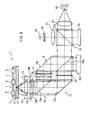
- FIG. 1 is an illustration showing a configuration of a pick-up of an optical information recording/reproducing apparatus as an optical information recording apparatus and an optical information reproducing apparatus according to the present embodiment and a configuration of an optical information recording medium according to the present embodiment.
- Fig. 2 is a block diagram of a general configuration of the optical information recording/reproducing apparatus according to the present embodiment.
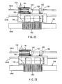
- the optical information recording medium 1 is configured by forming: a hologram layer 3 as an information recording layer for recording information utilizing volume holography; a reflecting film 5; and a protective film 4 in the order listed on one surface of a disk-shaped transparent substrate 2 formed from polycarbonate or the like.
- a plurality of address servo areas 6 as positioning regions extending linearly in the radial direction are provided at predetermined angular intervals at the interface between the hologram layer 3 and the protective layer 4. Sections in the form of sectors between the adjoining address servo areas 6 are data areas 7.
- Focus servo can be performed using a reflecting surface of the reflecting film 5.
- wobble pits may be used as the information for performing tracking servo.
- the transparent substrate 2 has an appropriate thickness of 0.6 mm or less
- the hologram layer 3 has an appropriate thickness of 10 ⁇ m or more.
- the hologram layer 3 is formed of a hologram material whose optical characteristics such as a refractive index, permittivity and reflectivity change depending on the intensity of light when illuminated with the light.
- photopolymer HRF-600 product name
- the reflecting film 5 is formed of aluminum.
- An optical information recording/reproducing apparatus 10 has: a spindle 81 to which the optical information recording medium 1 is mounted; a spindle motor 82 for rotating the spindle 81; and a spindle servo circuit 83 for controlling the spindle motor 82 to keep the rotating speed of the optical information recording medium 1 at a predetermined value.
- the optical information recording/reproducing apparatus 10 further has: a pick-up 11 for recording information in the optical information recording medium 1 by illuminating it with information light and recording reference light and for reproducing the information recorded in the optical information recording medium 1 by illuminating the optical information recording medium 1 with reference light for reproduction and by detecting reproduction light; and a driver 84 for allowing the pick-up 11 to move in the radial direction of the optical information recording medium 1.
- the optical information recording/reproducing apparatus 10 further has: a detection circuit 85 for detecting a focus error signal FE, a tracking error signal TE and a reproduction signal RF from a signal output by the pick-up 11; a focus servo circuit 86 for performing focus servo by driving an actuator in the pick-up 11 based on the focus error signal FE detected by the detection circuit 85 to move an objective lens in the direction of the thickness of the optical information recording medium 1; a tracking servo circuit 87 for performing tracking servo by driving the actuator in the pick-up 11 based on the tracking error signal TE detected by the detection circuit 85 to move the objective lens in the radial direction of the optical information recording medium 1; and a slide servo circuit 88 for performing slide servo by controlling the driver 84 based on the tracking error signal TE and a command from a controller to be described later to move the pick-up 11 in the radial direction of the optical information recording medium 1.
- the optical information recording/reproducing apparatus 10 further has: a signal processing circuit 89 for reproducing data recorded in the data areas 7 of the optical information recording medium 1 by decoding data output by a CCD array to be described later in the pick-up 11 and for reproducing a basic clock and determining an address from the reproduction signal RF from the detection circuit 85; a controller 90 for controlling the optical information recording/reproducing apparatus 10 as a whole; and an operating portion 91 for supplying various instructions to the controller 90.
- the controller 90 receives input of the basic clock and address information output by the signal processing circuit 89 and controls the pick-up 11, spindle servo circuit 83, slide servo circuit 88 and the like.
- the basic clock output by the signal processing circuit 89 is input to the spindle servo circuit 83.
- the controller 90 has a CPU (central processing unit), a ROM (read only memory) and a RAM (random access memory), and the CPU executes programs stored in the ROM using the RAM as a work area to realize the functions of the
- the detection circuit 85, focus servo circuit 86, tracking servo circuit 87 and slide servo circuit 88 correspond to the position control means.
- the pick-up 11 has: an objective lens 12 which faces the transparent substrate 2 of the optical information recording medium 1 when the optical information recording medium 1 is secured to the spindle 81; an actuator 13 capable of moving the objective lens 12 in the direction of the thickness of the optical information recording medium 1 and the radial direction of the same; and a double optically rotating plate 14 and a prism block 15 which are disposed on the side of the objective lens 12 opposite to the optical information recording medium 1 in the order listed which is the order of their closeness to the objective lens 12.
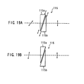
- the double optically rotating plate 14 has: an optically rotating plate 14L provided on the left side of the optical axis in Fig.
- the prism block 15 has a half-reflecting surface 15a and a reflecting surface 15b which are arranged in the order listed which is the order of their closeness to the double optically rotating plate 14.
- the normal directions of both of the half-reflecting surface 15a and the reflecting surface 15b are at 45° to the direction of the optical axis of the objective lens 12 and are in parallel with each other.
- the pick-up 11 further has a prism block 19 provided on a side of the prism block 15.
- the prism block 19 has: a reflecting surface 19a which is provided in a position associated with the half-reflecting surface 15a of the prism block 15 and which is in parallel with the half-reflecting surface 15a; and a half-reflecting surface 19b which is provided in a position associated with the reflecting surface 15b and which is in parallel with the reflecting surface 15b.
- the pick-up 11 further has a convex lens 16 and a phase-spatial light modulator 17 which are provided between the prism blocks 15 and 19 in positions associated with the half-reflecting surface 15a and reflecting surface 19a, and has a spatial light modulator 18 provided between the prism blocks 15 and 19 in a position associated with the reflecting surface 15b and the half-reflecting surface 19b.
- the phase-spatial light modulator 17 has a multiplicity of pixels arranged in the form of a grid and is capable of spatially modulating the phase of light by selecting a phase for light emitted by each of the pixels.
- a liquid crystal element may be used as the phase-spatial light modulator 17.
- the phase-spatial light modulator 17 corresponds to the phase modulation means .
- the spatial light modulator 18 has a multiplicity of pixels arranged in the form of a grid and is capable of generating information light carrying information by spatially modulating light in terms of intensity by selecting a light transmitting state or a light blocking state for each of the pixels.
- a liquid crystal element may be used as the spatial light modulator 18.
- the spatial light modulator 18 constitutes the information light generation means .
- the pick-up 11 further has a CCD array 20 as detection means provided in a direction in which return light from the optical information recording medium 1 is reflected by the half-reflecting surface 19b of the prism block 19 after being transmitted by the spatial light modulator 18.
- the pick-up 11 further has a beam splitter 23, a collimator lens 24 and a light source device 25 which are provided on the side of the prism block 19 opposite to the spatial light modulator 18 in the order listed which is the order of their closeness to the prism block 19.
- the beam splitter 23 has a half-reflecting surface 23a whose normal direction is tilted at an angle of 45° to the direction of the optical axis of the collimator lens 24.
- the light source device 25 emits coherent linearly polarized light and may be, for example, a semiconductor laser.
- the pick-up 11 further has: a photodetector 26 provided in a direction in which light from the light source device 25 is reflected by the half-reflecting surface 23a of the beam splitter 23; and a convex lens 27, a cylindrical lens 28 and a quadruple photodetector 29 which are provided on the side of the beam splitter 23 opposite to the photodetector 26 in the order listed which is the order of their closeness to the beam splitter 23.
- the photodetector 26 receives light from the light source device 25, and the output of the same is used to adjust the output of the light source device 25 automatically. As shown in Fig.
- the quadruple photodetector 29 has four light-receiving portions 29a through 29d divided by a division line 30a in parallel with a direction corresponding to the direction of tracks of the optical information recording medium 1 and a division line 30b orthogonal thereto.
- the cylindrical lens 28 is provided such that the central axis of the cylindrical surface thereof is at an angle of 45° to the division lines 30a and 30b of the quadruple photodetector 29.
- the phase-spatial light modulator 17, the spatial light modulator 18 and the light source device 25 in the pick-up 11 are controlled by the controller 90 in Fig. 2 .
- the controller 90 has information of a plurality of modulation patterns for spatially modulating the phase of light with the phase-spatial light modulator 17.
- the operating portion 91 allows selection of any one of the plurality of modulation patterns.
- the controller 90 supplies information of a modulation pattern selected by itself or by the operating portion 91 to the phase-spatial light modulator 17 in accordance with predetermined conditions, and the phase-spatial light modulator 17 spatially modulates the phase of light, in accordance with the modulation pattern information supplied by the controller 90, in the modulation pattern associated therewith in accordance with the information.
- the reflectivity of each of the half-reflecting surfaces 15a and 19b in the pick-up 11 is appropriately set, for example, such that information light and reference light for recording incident upon the optical information recording medium 1 have the same intensity.
- Fig. 3 is a block diagram of the detection circuit 85 for detecting the focus error signal FE, the tracking error signal TE and the reproduction signal RF based on the output of the quadruple photodetector 29.
- the detection circuit 85 has: an adder 31 for adding the output of each of the diagonal light-receiving portions 29a and 29d of the quadruple photodetector 29; an adder 32 for adding the output of each of the diagonal light-receiving portions 29b and 29c of the quadruple photodetector 29; a subtracter 33 for calculating the difference between the outputs of the adders 31 and 32 to generate the focus error signal FE based on an astigmatic method; an adder 34 for adding the output of each of the light-receiving portions 29a and 29b of the quadruple photodetector 29 which are adjacent to each other in the direction of tracks thereof; an adder 35 for adding the output of each of the light-receiving portions 29c and 29d of the quadrup
- the optical information recording medium 1 is rotated by the spindle motor 82 under control to maintain a predetermined rotating speed.
- a servo operation will now be described with reference to Fig. 4 .
- all pixels of the spatial light modulator 18 are in a transmitting state.
- the output of the emission of light from the light source device 25 is set at a low output for reproduction.
- the controller 90 predicts the timing at which light that has exited the objective lens 12 passes through the address servo areas 6 based on a basic clock reproduced from a reproduction signal RF and maintains the above-described setting while the light from the objective lens 12 passes through the address servo areas 6.
- Light emitted by the light source device 25 is collimated by the collimator lens 24 to impinge upon the beam splitter 23, and a part of the quantity of light is transmitted by the half-reflecting surface 23a and another part is reflected thereby.
- the light reflected by the half-reflecting surface 23a is received by the photodetector 26.
- the light transmitted by the half-reflecting surface 23a impinges upon the prism block 19, and a part of the quantity of light is transmitted by the half-reflecting surface 19b.
- the light transmitted by the half-reflecting surface 19b passes through the spatial light modulator 18 to be reflected by the reflecting surface 15b of the prism block 15, and a part of the quantity of light is transmitted by the half-reflecting surface 15a, passes through the double optically rotating plate 14, and is collected by the objective lens 12 to be projected upon the optical information recording medium 1 such that it converges at the interface between the hologram layer 3 and the protective layer 4 of the optical information recording medium 1.
- This light is reflected by the reflecting film 5 of the optical information recording medium 1, modulated by embossed pits in the address servo areas 6 while being reflected, and then returned to the objective lens 12.
- the return light from the optical information recording medium 1 is collimated by the objective lens 12 and passes through the double optically rotating plate 14 again to impinge upon the prism block 15, and a part of the quantity of light is transmitted by the half-reflecting surface 15a.
- the return light transmitted by the half-reflecting surface 15a is reflected by the reflecting surface 15b and is transmitted by the spatial light modulator 18, and a part of the quantity of light is transmitted by the half-reflecting surface 19b of the prism block 19.
- the detection circuit 85 shown in Fig. 3 Based on the output of the quadruple photodetector 29, the detection circuit 85 shown in Fig. 3 generates the focus error signal FE, tracking error signal TE and reproduction signal RF based on which focus servo and tracking servo is performed; the basic clock is generated; and addresses are determined.
- the pick-up 11 is configured similarly to a configuration of a pick-up for recording on or reproduction from normal optical disks such as CDs (compact disks), DVDs (digital video disks or digital versatile disks) and HSs (hyper storage disks). It is therefore possible to configure the optical information recording/reproducing apparatus 10 according to the present embodiment to be compatible with normal optical disk devices.
- CDs compact disks
- DVDs digital video disks or digital versatile disks
- HSs hyper storage disks
- A-polarized light is linear polarized light obtained by rotating the polarizing direction of S-polarized light at -45° or by rotating the polarizing direction of P-polarized light at +45°
- B-polarized light is linear polarized light obtained by rotating the polarizing direction of S-polarized light at +45° or by rotating the polarizing direction of P-polarized light at -45°.
- the polarizing directions of the A-polarized light and B-polarized light are orthogonal to each other.
- S-polarized light is linear polarized light whose polarizing direction is perpendicular to the plane of incidence (plane of Fig. 1 ), and P-polarized light is linear polarized light whose polarizing direction is in parallel with the plane of incidence.
- Fig. 6 is an illustration of a state of the pick-up 11 during recording.
- the spatial light modulator 18 generates information light by selecting a transmitting state (hereinafter also referred to as “on”) or a blocking state (hereinafter also referred to as "off") for each pixel depending on the information to be recorded to spatially modulate the light that is passing through it.
- a transmitting state hereinafter also referred to as "on”
- a blocking state hereinafter also referred to as "off”
- two pixels represent information of one bit, and one of two pixels associated with information of one bit is always on and the other is always off.
- the phase-spatial light modulator 17 generates reference light for recording having a spatially modulated phase by selectively applying a phase difference of 0 (rad) or ⁇ (rad) from a predetermined reference phase to each pixel according to a predetermined modulation pattern to spatially modulate the phase of light passing therethrough.
- the controller 90 supplies information of a modulation pattern selected by itself or by the operating portion 91 in accordance with predetermined conditions to the phase-spatial light modulator 17 which in turn spatially modulates the phase of light passing therethrough according to the modulation pattern information supplied by the controller 90.
- the output of light emitted by the light source device 25 is set at a high output to be used for recording in terms of the pulse thereof.
- the controller 90 predicts timing at which light that has exited the objective lens 12 passes through the data areas 7 and maintains the above-described setting while the light from the objective lens 12 is passing through the data areas 7. While the light from the objective lens 12 is passing through the data areas 7, neither focus servo nor tracking servo is performed, and the objective lens 12 is fixed.
- the following description is on an assumption that the light source device 25 emits P-polarized light.
- P-polarized light emitted by the light source device 25 is collimated by the collimator lens 24 to impinge upon the beam splitter 23, and a part of the quantity of light is transmitted by the half-reflecting surface 23a to impinge upon the prism block 19.
- a part of the light incident upon the prism block 19 is transmitted by the half-reflecting surface 19b, and another part of the quantity of light is reflected by the half-reflecting surface 19b.
- the light transmitted by the half-reflecting surface 19b passes through the spatial light modulator 18 in which it is spatially modulated into information light according to the information to be recorded.
- the information light is reflected by the reflecting surface 15b of the prism block 15, and a part of the quantity of light is transmitted by the half-reflecting surface 15a to pass through the double optically rotating plate 14.
- the polarizing direction of light passing through the optically rotating plate 14L of the double optically rotating plate 14 is rotated at +45° to provide A-polarized light
- the polarizing direction of light passing through the optically rotating plate 14R is rotated at -45° to provide B-polarized light.
- the information light having passed through the double optically rotating plate 14 is collected by the objective lens 12 and is projected upon the optical information recording medium 1 such that it converges on the interface between the hologram layer 3 and the protective layer 4, i.e., on the reflecting film 5 of the optical information recording medium 1.
- the light reflected by the half-reflecting surface 19b of the prism block 19 is reflected by the reflecting surface 19a to pass through the phase-spatial light modulator 17 in which the phase of light is spatially modulated according to a predetermined modulation pattern to provide reference light for recording.
- the reference light for recording passes through the convex lens 16 to become convergent light.
- a part of the reference light for recording is reflected by the half-reflecting surface 15a of the prism block 15 to pass through the double optically rotating plate 14.
- the polarizing direction of light which has passed through the optically rotating plate 14L of the double optically rotating plate 14 is rotated at +45° to provide A-polarized light
- the polarizing direction of light which has passed through the optically rotating plate 14R is rotated at -45° to provide B-polarized light.
- the reference light for recording which has passed through the double optically rotating plate 14 is collected by the objective lens 12 to be projected upon the optical information recording medium 1.
- the light temporarily converges to a minimum diameter before the interface between the hologram layer 3 and the protective layer 4, and thereafter divergingly passes through the hologram layer 3.
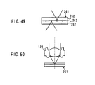
- Figs. 7 and 8 are illustrations of states of light during recording.
- the reference number 61 represents P-polarized light
- the reference number 63 represents A-polarized light
- the reference number 64 represents B-polarized light.
- information light 51L which has passed through the optically rotating plate 14L of the double optically rotating plate 14 becomes A-polarized light which illuminates the optical information recording medium 1 through the objective lens 12, passes through the hologram layer 3, converges to a minimum diameter on the reflecting film 5 and passes through the hologram layer 3 again after being reflected by the reflecting film 5.
- Reference light 52L for recording which has passed through the optically rotating plate 14L of the double optically rotating plate 14 becomes A-polarized light which illuminates the optical information recording medium 1 through the objective lens 12, temporarily converges to a minimum diameter before the interface between the hologram layer 3 and the protective layer 4 and divergingly passes through the hologram layer 3.
- Interference occurs in the hologram layer 3 between the A-polarized information light 51L reflected by the reflecting film 5 and the A-polarized reference light 52L for recording traveling toward the reflecting film 5, so that an interference pattern is formed, and the interference pattern is volumetrically recorded in the hologram layer 3 when the light emitted by the light source device 20 is at the high output.
- information light 51R which has passed through the optically rotating plate 14R of the double optically rotating plate 14 becomes B-polarized light which illuminates the optical information recording medium 1 through the objective lens 12, passes through the hologram layer 3, converges to a minimum diameter on the reflecting film 5 and passes through the hologram layer 3 again after being reflected by the reflecting film 5.
- Reference light 52R for recording which has passed through the optically rotating plate 14R of the double optically rotating plate 14 becomes B-polarized light which illuminates the optical information recording medium 1 through the objective lens 12, temporarily converges to a minimum diameter before the interface between the hologram layer 3 and the protective layer 4 and divergingly passes through the hologram layer 3.
- Interference occurs in the hologram layer 3 between the B-polarized information light 51R reflected by the reflecting film 5 and the B-polarized reference light 52R for recording traveling toward the reflecting film 5, so that an interference pattern is formed, and the interference pattern is volumetrically recorded in the hologram layer 3 when the light emitted by the light source device 20 is at the high output.
- the information light and the reference light for recording illuminate the hologram layer 3 on the same side thereof such that the optical axes of the information light and the reference light for recording are located on the same line.
- phase-encoding multiplexing can be performed to record information in the same location of the hologram layer 3 on a multiplex basis by performing the recording operation a plurality of times in the same location of the hologram layer 3 with the modulation pattern for the reference light for recording changed.
- a reflection type (Lippmann type) hologram is thus formed in the hologram layer 3.
- No interference occurs between the A-polarized information light 51L and the B-polarized reference light 52R for recording because their polarizing directions are orthogonal to each other and, similarly, no interference occurs between the B-polarized information light 51R and the A-polarized reference light 52L for recording because their polarizing directions are orthogonal to each other.
- the present embodiment makes it possible to prevent the occurrence of any unnecessary interference fringe, thereby preventing any reduction in an SN (signal-to-noise) ratio.
- the information light is projected upon the optical information recording medium 1 such that it converges to a minimum diameter on the interface between the hologram layer 3 and the protective layer 4, and is reflected by the reflecting film 5 of the optical information recording medium 1 to return to the objective lens 12.
- the return light is incident upon the quadruple photodetector 29 in the same manner as in the servo operation. According to the present embodiment, it is therefore possible to perform focus servo also during recording utilizing the light incident upon the quadruple photodetector 29.
- the reference light for recording converges to a minimum diameter before the interface between the hologram layer 3 and the protective layer 4 in the optical information recording medium 1 to become divergent light, it forms no image on the quadruple photodetector 29 even though it is reflected by the reflecting film 5 of the optical information recording medium 1 to return to the objective lens 12.
- the size of a region (hologram) in which one interference pattern resulting from information light and reference light is volumetrically recorded in the hologram 3 can be arbitrarily determined by moving the convex lens 16 back and forth or changing the magnification of the same.
- the controller 90 supplies information of a modulation pattern for the reference light for recording which was supplied at recording of the information which is now to be reproduced to the phase-spatial light modulator 17, and the phase-spatial light modulator 17 spatially modulates the phase of light passing therethrough according to the modulation pattern information supplied by the controller 90 to generate reference light for reproduction having a spatially modulated optical phase.
- the output of the light emitted by the light source device 25 is set at a low output to be used for reproduction.
- the controller 90 predicts timing at which light that has exited the objective lens 12 passes through the data areas 7 and maintains the above-described setting while the light from the objective lens 12 is passing through the data areas 7. While the light from the objective lens 12 is passing through the data areas 7, neither focus servo nor tracking servo is performed, and the objective lens 12 is fixed.
- P-polarized light emitted by the light source device 25 is collimated by the collimator lens 24 to impinge upon the beam splitter 23, and a part of the quantity of light is transmitted by the half-reflecting surface 23a to impinge upon the prism block 19.
- a part of the light incident upon the prism block 19 is reflected by the half-reflecting surface 19b.
- the reflected light is reflected by the reflecting surface 19a to pass through the phase-spatial light modulator 17 and, at that time, the phase of the light is spatially modulated in a predetermined modulation pattern to provide reference light for reproduction.
- the reference light for reproduction passes through the convex lens 16 to become convergent light.
- a part of the quantity of the reference light for reproduction is reflected by the half-reflecting surface 15a of the prism block 15 to pass through the double optically rotating plate 14.
- the polarizing direction of light passing through the optically rotating plate 14L of the double optically rotating plate 14 is rotated at +45° to provide A-polarized light
- the polarizing direction of light passing through the optically rotating plate 14R is rotated at -45° to provide B-polarized light.
- the reference light for reproduction that has passed through the double optically rotating plate 14 is collected by the objective lens 12 and is projected upon the optical information recording medium 1. It temporarily converges to a minimum diameter before the interface between the hologram layer 3 and the protective layer 4, and thereafter divergingly passes through the hologram layer 3.
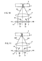
- Figs. 10 and 11 are illustrations of states of light during reproduction.
- the reference number 61 represents P-polarized light; the reference number 62 represents S-polarized light; the reference number 63 represents A-polarized light; and the reference number 64 represents B-polarized light.
- reference light 53L for reproduction which has passed through the optically rotating plate 14L of the double optically rotating plate 14 becomes A-polarized light which illuminates the optical information recording medium 1 through the objective lens 12, temporarily converges to a minimum diameter before the interface between the hologram layer 3 and the protective layer 4, and thereafter divergingly passes through the hologram layer 3.
- the hologram layer 3 generates reproduction light 54L that is associated with the information light 51L for recording.
- the reproduction light 54L travels toward the objective lens 12 to be collimated by the objective lens 12, and passes through the double optically rotating plate 14 again to become S-polarized light.
- reference light 53R for reproduction which has passed through the optically rotating plate 14R of the double optically rotating plate 14 becomes B-polarized light which illuminates the optical information recording medium 1 through the objective lens 12, temporarily converges to a minimum diameter before the interface between the hologram layer 3 and the protective layer 4, and thereafter divergingly passes through the hologram layer 3.
- the hologram layer 3 generates reproduction light 54R that is associated with the information light 51R for recording.
- the reproduction light 54R travels toward the objective lens 12 to be collimated by the objective lens 12, and passes through the double optically rotating plate 14 again to become S-polarized light.
- the reproduction light transmitted by the half-reflecting surface 15a is reflected by the half-reflecting surface 15a to pass through the spatial light modulator 18, and a part of the quantity of light is reflected by the half-reflecting surface 19b of the prism block 19 to be incident upon and detected by the CCD array 20.
- a pattern originating from an on/off operation of the spatial light modulator 18 during recording is formed on the CCD array 20, and information is reproduced by detecting this pattern.
- the illumination with the reference light for reproduction and the collection of reproduction light is carried out on the same side of the hologram layer 3 such that the optical axes of the reference light for reproduction and the reproduction light are located on the same line.
- the present embodiment a part of the reproduction light impinges upon the quadruple photodetector 29 similarly to the return light during the servo operation.
- the present embodiment therefore makes it possible to perform focus servo even during reproduction utilizing the light incident upon the quadruple photodetector 29. Since the reference light for reproduction converges to a minimum diameter before the interface between the hologram layer 3 and the protective layer 4 of the optical information recording medium 1 to become divergent light, it forms no image on the quadruple photodetector 29 when it is reflected by the reflecting film 5 of the optical information recording medium 1 to return toward the objective lens 12.
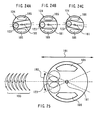
- the aperture is divided by the spatial light modulator 18 into a plurality of pixels 72.
- a pixel 72 serves as a minimum unit of two-dimensional pattern data.
- two pixels represent one bit of digital data "0" or "1".
- One of two pixels associated with one bit of information is on, and the other is off.
- a pair of pixels which are both on or off represent error data.
- Fig. 13A shows a pair of pixels 73 associated with one bit of digital data. The region where such a pair 73 exists is hereinafter referred to as "data region”.
- reference position information indicating a reference position in a pattern of reproduction light is included in the information light utilizing the fact that a pair of pixels which are both on or off represent error data.
- error data are intentionally provided in a predetermined pattern in a cross-shaped region 74 constituted by a part in parallel with the division line of the double optically rotating plate 14 having a width equal to two pixels and a part perpendicular to the division line having a width equal to two pixels.
- This pattern of error data is hereinafter referred to as "pixel pattern for tracking".
- the pixel pattern for tracking serves as the reference position information.
- the reference number 75 represents pixels which are on
- the reference number 76 represents pixels that are off.
- a region 77 consisting of four pixels in the middle is always kept off.
- a two-dimensional pattern as shown in Fig. 14A is obtained by combining a pixel pattern for tracking with a pattern associated with data to be recorded.
- regions other than the data regions are off in the upper half of the figure and are on in the lower half, and pixels in the data regions which are contiguous with the regions other than the data regions are in a state which is the reverse of the state of the regions other than the data regions, i.e., they are on if the regions other than the data regions are off, and are off if the regions other than the data regions are on. It is therefore possible to clearly detect the boundary of data regions from data detected by the CCD array 20.
- a pattern is recorded in the hologram layer 3 which originates from interference between information light spatially modulated according to a two-dimensional pattern as shown in Fig. 14A and reference light for recording.
- a pattern of reproduction light obtained during reproduction has a contrast and an SN ratio lower than those at recording.
- a pattern of reproduction light as shown in Fig. 14B is detected by the CCD array 20 to determine the data and, at this time, the data are determined by recognizing the pixel pattern for tracking and using the position of the same as a reference position.
- Fig. 15A is a conceptual representation of contents of data determined from a pattern of reproduction light. Each of regions in the figure having reference numbers such as A-1-1 represents one bit of data.
- a data region is divided at the cross-shaped region 74 having a pixel pattern for tracking recorded therein into four regions 78A, 78B, 78C and 78D.
- a rectangular region is formed by combining the diagonal regions 78A and 78C; another rectangular region is similarly formed by combining the diagonal regions 78B and 78D; and an ECC table is formed by arranging the two rectangular regions vertically.
- An ECC table is a table of data formed by adding error-correcting codes (ECCs) such as CRC (cyclic redundancy check) codes to data to be recorded.
- Fig. 15B shows an example of an ECC table comprising n rows and m columns, and other arrays may be freely designed.
- the data array shown in Fig. 15A utilizes a part of the ECC table shown in Fig. 15B , and parts of the ECC table shown in Fig. 15B which are not used in the data array shown in Fig. 15A have the same value regardless of the contents of data.
- an ECC table as shown in Fig. 15B is divided into four regions 78A, 78B, 78C and 78D as shown in Fig.
- the illumination of the optical information recording medium 1 with reference light for recording and information light during recording and the illumination of the optical information recording medium 1 with reference light for reproduction and the collection of reproduction light during reproduction are all carried out on the same side of the optical information recording medium 1 and on the same axis while allowing multiplex recording of information in the optical information recording medium 1 utilizing phase-encoding multiplexing.
- This makes it possible to configure the optical system for recording or reproduction smaller than those in prior-art holographic recording systems and eliminates the problem of stray light as encountered in prior-art holographic recording systems.
- the present embodiment also makes it possible to configure the optical system for recording and reproduction in the form of the pick-up 11 which is similar to normal optical disk devices. Therefore, random access to the optical information recording medium 1 can be easily performed.
- information required to perform focus servo and tracking servo can be recorded in the optical information recording medium 1 to allow focus servo and tracking servo to be performed using the information.
- This makes it possible to position light for recording or reproduction accurately, which results in improved removability, facilitates random access and allows increases in a recording density, recording capacity and transfer rate.
- the present embodiment allows dramatic increases in a recording density, recording capacity and transfer rate as a result of the capability of multiplex recording of information based on phase-encoding multiplexing. For example, when a series of information is recorded in the same location of the hologram layer 3 on a multiplex basis while changing the modulation pattern for the reference light for recording, the information can be recorded and reproduced at a very high speed.
- the present embodiment also makes it possible to achieve copy protection and security easily because information recorded in the optical information recording medium 1 cannot be reproduced unless reference light for reproduction is used which has the same modulation pattern as that of the reference light for recording used to record the information.
- the present embodiment also makes it possible to provide services e.g., a service in which a multiplicity of kinds of information (e.g., various kinds of software) with different modulation patterns for reference light are recorded in optical information recording media 1; the optical information recording media 1 themselves are provided to users at a relatively low price; and pieces of information of the reference light modulation patterns to enable reproduction of each of the various kinds of information are separately sold to the users as key information as requested by the users.
- a multiplicity of kinds of information e.g., various kinds of software
- a pattern of reproduction light can be easily recognized because reference position information indicating a reference position for the pattern of the reproduction light is included in the information light.
- the optical information recording/reproducing apparatus 10 is compatible with conventional optical disk devices because information recorded in the form of embossed pits in a recording medium can be reproduced by setting the pick-up 11 in the servo state shown in Fig. 4 .
- optical information recording/reproducing apparatus 10 With the optical information recording/reproducing apparatus 10 according to the present embodiment, it is quite difficult to copy an optical information recording medium 1 having information recorded therein because each item of information recorded in the optical information recording medium 1 on a multiplex basis is associated with a different modulation pattern for the phase of the reference light. This makes it possible to prevent illegal copying.
- the hologram layer 3 in which information is recorded utilizing holography is separated from the layer in which information of addresses and the like is recorded in the form of embossed pits, those two layers must be associated with each other to copy the optical information recording medium 1 having information recorded therein. Copying is difficult also from this point of view, which makes it possible to prevent illegal copying.
- the present embodiment is an example in which multiplex recording is enabled by using phase-encoding multiplexing and hole burning type wavelength multiplexing in combination.
- the general configuration of the optical information recording/reproducing apparatus according to the present embodiment is substantially the same as the configuration of the optical information recording/reproducing apparatus 10 according to the first embodiment shown in Fig. 2 .
- Hole burning is a phenomenon in which a change in absorbance occurs in an absorption spectrum in the position of the wavelength of incident light and is also referred to as "photochemical hole burning".
- a material that causes hole burning i.e., a material that causes a change in absorbance in an absorption spectrum in the position of the wavelength of incident light is referred to as "hole burning material”.
- a hole burning material is a material obtained by dispersing light-absorbing center materials (referred to as "guests”) such as pigment in a medium (referred to as "host”) having an irregular structure, e.g., an amorphous structure.
- such a hole burning material exhibits a broad absorption spectrum that is attributable to overlapping of absorption spectra of a multiplicity of guests.
- light such as laser light having a certain wavelength (a wavelength within the absorption band of the hole burning material)
- a reduction of absorbance occurs in the absorption spectrum of the hole burning material in the position of the wavelength of the illuminating light.
- Fig. 16 shows a state of the absorption spectrum of a hole burning material in which a reduction of absorbance has occurred in a plurality of wavelength positions as a result of illumination with light having a plurality of wavelengths.
- the regions of a hole burning material where a reduction of absorbance has occurred when illuminated with light are referred to as "holes". Since such holes are extremely small, a plurality of pieces of information with different wavelengths can be recorded on a hole burning material on a multiplex basis, and such a method for multiplex recording is referred to as "hole burning type wavelength multiplexing". Since the size of holes is on the order of 10 -2 nm, it is assumed that multiplicity on the order of 10 3 to 10 4 can be achieved with a hole burning material.
- the present embodiment makes it possible to form a plurality of holograms with different wavelengths on a hole burning material utilizing hole burning type wavelength multiplexing as described above.
- a hologram layer 3 of an optical information recording medium 1 used in the optical information recording/reproducing apparatus according to the present embodiment is formed from a hole burning material as described above.
- a light source device 25 in a pick-up 11 is capable of selectively emitting coherent light having a plurality of wavelengths within the absorption band of the hole burning material from which the hologram layer 3 is formed.
- the light source device 25 may be a wavelength variable laser device having a dye laser and a wavelength selecting element (a prism, diffraction grating or the like) for selecting a wavelength of light emitted by the dye laser; a wavelength variable laser device having a laser and a wavelength selecting element utilizing a non-linear optical element for converting the wavelength of light emitted by the laser; or the like.
- An operating portion 91 allows a modulation pattern for reference light to be selected from among a plurality of modulation patterns similarly to that in the first embodiment and allows the wavelength of light emitted by the light source device 25 to be selected from among a plurality of selectable wavelengths.
- a controller 90 supplies information of a wavelength selected by itself or the operating portion 91 in accordance with predetermined conditions to the light source device 25 and, according to the wavelength information supplied by the controller 90, the light source device 25 emits light having the wavelength associated therewith.
- the light source device 25 of the present embodiment corresponds to the wavelength selection means.
- the configuration of the optical information recording/reproducing apparatus according to the present embodiment is otherwise the same as that of the first embodiment.
- the wavelength of light emitted by the light source device 25 is selected from among a plurality of selectable wavelengths.
- information light and reference light for recording having the selected wavelength are generated.
- multiplex recording can be carried out utilizing hole burning type wavelength multiplexing by performing a recording operation a plurality of times with the wavelength of the information light and the reference light for recording varied in the same location of the hologram layer 3.
- multiplex recording can be carried out which involves both of phase-encoding multiplexing and hole burning type wavelength multiplexing by performing a recording operation a plurality of times with the modulation pattern of the reference light for recording varied at a certain wavelength in the same location of the hologram layer 3 and further performing the recording operation a plurality of times with the modulation pattern of the reference light varied similarly at a different wavelength.
- multiplicity of M x N can be achieved where N represents multiplicity achieved by phase-encoding multiplexing and M represents multiplicity achieved by hole burning type wavelength multiplexing. Therefore, the present embodiment makes it possible to achieve greater increases in the recording density, recording capacity and transfer rate than achievable in the first embodiment.
- the present embodiment makes it possible to achieve copy protection and security easily like the first embodiment because information recorded in the optical information recording medium 1 cannot be reproduced unless reference light for reproduction is used which has the same wavelength as that of the information light and the reference light for recording used to record the information. Further, when multiplex recording is performed as a combination of phase-encoding multiplexing and hole burning type wavelength multiplexing, a higher level of copy protection and security can be achieved because reproduction cannot be performed unless reference light for reproduction is used which has the same wavelength as that of the information light and the reference light for recording used to record the information, and which has the same modulation pattern as that of the reference light for recording.
- the present embodiment also makes it possible to provide services e.g., a service in which a multiplicity of kinds of information (e.g., various kinds of software) with different wavelengths of the information light and the reference light for recording or different modulation patterns of reference light are recorded in optical information recording media 1; the optical information recording media 1 themselves are provided to users at a relatively low price; and pieces of information of the wavelengths and the modulation patterns of the reference light to enable reproduction of each of the various kinds of information are separately sold to the users as key information as requested by the users.
- a multiplicity of kinds of information e.g., various kinds of software
- optical information recording media 1 themselves are provided to users at a relatively low price
- pieces of information of the wavelengths and the modulation patterns of the reference light to enable reproduction of each of the various kinds of information are separately sold to the users as key information as requested by the users.
- optical information recording/reproducing apparatus according to a third embodiment of the present invention will now be described.
- the general configuration of the optical information recording/reproducing apparatus according to the present embodiment is substantially the same as the configuration of the optical information recording/reproducing apparatus 10 according to the first embodiment shown in Fig. 2 except that the configuration of the pick-up is different from that in the first embodiment.
- Fig. 17 is an illustration of the configuration of the pick-up according to the present embodiment
- Fig. 18 is a plan view of a configuration of an optical unit including various elements that form the pick-up.
- the pick-up 111 has: a light source device 112 which emits coherent linearly polarized laser light; and a collimator lens 113, a neutral density filter (hereinafter referred to as "ND filter") 114, a rotating optical element 115, a polarization beam splitter 116, a phase-spatial light modulator 117, a beam splitter 118 and a photodetector 119 which are provided in the traveling direction of the light emitted by the light source device 112 in the order listed that is the order of their closeness to the light source device 112.
- the light source device 112 emits S-polarized linear light or P-polarized linear light.
- the collimator lens 113 collimates the light emitted by the light source device 112 to emit parallel beams.
- the ND filter 114 has the property of making the intensity distribution of the light emitted by the collimator lens 113 uniform.
- the optically rotating optical element 115 optically rotates the light emitted by the ND filter 114 to emit light including S-polarized components and P-polarized components. For example, a 1/2 wavelength plate or optically rotating plate is used as the rotating optical element 115.
- the polarization beam splitter 116 has a polarization beam splitter surface 116a which reflects the S-polarized components of the light emitted by the rotating optical element 115 and which transmits the P-polarized components.
- the phase-spatial light modulator 117 is similar to the phase-spatial light modulator 17 in the first embodiment.
- the beam splitter 118 has a beam splitter surface 118a.
- the beam splitter surface 118a transmits 20% of the P-polarized components and reflects 80% of the same.
- the photodetector 119 is used to monitor the quantity of reference light for automatic power control (hereinafter represented by "APC") over the reference light.
- a light-receiving portion of the photodetector 119 may be divided into a plurality of regions to allow the adjustment of the intensity distribution of reference light.
- the pick-up 111 further has a polarization beam splitter 120, a double optically rotating plate 121 and a raising mirror 122 which are provided in the traveling direction of the light emitted by the light source device 112 and reflected by the beam splitter surface 118a of the beam splitter 118 in the order listed that is the order of their closeness to the beam splitter 118.
- the polarization beam splitter 120 has a polarization beam splitter surface 120a for reflecting S-polarized components in light incident thereupon and for transmitting P-polarized components therein.
- the double optically rotating plate 121 has an optically rotating plate 121R provided on the right side of the optical axis in Fig. 17 and an optically rotating plate 121L provided on the left side of the optical axis.
- the optically rotating plates 121R and 121L are similar to the optically rotating plates 14R and 14L of the double optically rotating plate 14 in the first embodiment.
- the optically rotating plate 121R optically rotates a polarizing direction at -45°
- the optically rotating plate 121L optically rotates a polarizing direction at +45°.
- the raising mirror 122 has a reflecting surface which is tilted at 45° relative to the optical axis of light from the double optically rotating plate 121 to reflect the light from the double optically rotating plate 121 in the direction perpendicular to the plane of Fig. 17 .
- the pick-up 111 further has: an objective lens 123 provided in the direction in which the light from the double optically rotating plate 121 travels after being reflected by the reflecting surface of the raising mirror 122 such that it faces a transparent substrate 2 of an optical information recording medium 1 when the optical information recording medium 1 is secured to a spindle 81; and has an actuator 124 (see Fig. 18 ) capable of moving the objective lens 123 in the direction of the thickness of the optical information recording medium 1 and the direction of tracks thereof.
- the pick-up 111 further has a spatial light modulator 125, a convex lens 126, a beam splitter 127 and a photodetector 128 which are provided in the traveling direction of the light emitted by the light source device 112 and reflected by the polarization beam splitter surface 116a of the polarization beam splitter 116 in the order listed that is the order of their closeness to the polarization beam splitter 116.
- the spatial light modulator 125 is similar to the spatial light modulator 18 in the first embodiment.
- the convex lens 126 has a function of converging information light before reference light for recording in the optical information recording medium 1 to form a region of interference between the reference light for recording and the information light.
- the size of the region of interference between the reference light for recording and the information light can be adjusted by adjusting the position of the convex lens 126.
- the beam splitter 127 has a beam splitter surface 127a.
- the beam splitter surface 127a transmits 20% of S-polarized components and reflects 80% of the same.
- the photodetector 128 is used to monitor the quantity of information light to thereby perform APC on the information light.
- a light-receiving portion of the photodetector 128 may be divided into a plurality of regions to allow the adjustment of the intensity distribution of information light.
- Light that impinges upon the beam splitter 127 from the convex lens 126 to be reflected by the beam splitter surface 127a is incident upon the polarization beam splitter 120.
- the pick-up 111 further has a convex lens 129, a cylindrical lens 130 and a quadruple photodetector 131 which are provided on the side of the beam splitter 127 opposite to the polarization beam splitter 120 in the order listed which is the order of their closeness to the beam splitter 127.
- the quadruple photodetector 131 is similar to the quadruple photodetector 29 in the first embodiment.
- the cylindrical lens 28 is provided such that the center axis of a cylindrical surface thereof defines an angle of 45° to a division line of the quadruple photodetector 131.
- the pick-up 111 further has an imaging lens 132 and a CCD array 133 which are provided on the side of the beam splitter 118 opposite to the polarization beam splitter 120 in the order listed that is the order of their closeness to the beam splitter 118.
- the pick-up 111 further has a collimator lens 134 and a fixing light source device 135 which are provided on the side of the polarization beam splitter 116 opposite to the spatial light modulator 125 in the order listed that is the order of their closeness to the polarization beam splitter 116.
- the fixing light source device 135 emits light for fixing information recorded in the hologram layer 3 of the optical information recording medium 1, e.g., ultraviolet light having a wavelength of 266 nm.
- a laser light source, a light source device for passing light emitted by a laser light source through a non-linear optical medium to emit the light with the wavelength thereof converted, or the like may be used as such a fixing light source device 135.
- the collimator lens 134 collimates light emitted by the fixing light source device 135. According to the present embodiment, the fixing light source device 135 emits S-polarized light.
- an optical unit 140 has an optical unit body 141.
- Fig. 18 shows only the region of a bottom surface of the optical unit body 141. Attached to the optical unit body 141 are the above-described collimator lens 113, ND filter 114, rotating optical element 115, polarization beam splitter 116, phase-spatial light modulator 117, beam splitter 118, polarization beam splitter 120, double optically rotating plate 121, raising mirror 122, spatial light modulator 125, convex lens 126, beam splitter 127, convex lens 129, cylindrical lens 130, imaging lens 132 and collimator lens 134.
- Fig. 18 shows an example of the use of a 1/2 wavelength plate as the rotating optical element 115.
- a motor 142 and a gear 143 for transmitting the rotation of an output shaft of the motor 142 to the rotating optical element 115 are provided in the optical unit body 141 in order to adjust the ratio between S-polarized components and P-polarized components in light emitted by the rotating optical element 115.
- Figs. 19A and 19B show an example of the rotating optical element 115 in which optically rotating plates are used.
- the rotating optical element 115 in this example has two wedge-shaped optically rotating plates 115a and 115b that are in a face-to-face relationship with each other. At least either of the optically rotating plates 115a and 115b is displaced by a driving device which is not shown in the directions of the arrows in the figures to change the combined thickness of the optically rotating plates 115a and 115b at an overlap between the optically rotating plates 115a and 115b as shown in Figs. 19A and 19B .
- a large combined thickness of the optically rotating plates 115a and 115b as shown in Fig. 19A results in a large rotating angle
- a small combined thickness of the optically rotating plates 115a and 115b as shown in Fig. 19B results in a small rotating angle.
- the actuator 124 is mounted on a top surface of the optical unit body 141.
- the light source device 112 is integral with a driving circuit 145 for driving the light source device 112 and is mounted on a lateral surface of the unit body 141 along with the driving circuit 145.
- the photodetector 119 is integral with an APC circuit 146 and is mounted to a lateral surface of the unit body 141 along with the APC circuit 146.
- the APC circuit 146 amplifies the output of the photodetector 119 to generate a signal APC ref used for APC carried out on reference light.
- the photodetector 128 is integral with an APC circuit 147 and is mounted to a lateral surface of the unit body 141 along with the APC circuit 147.
- the APC circuit 147 amplifies the output of the photodetector 119 to generate a signal APC obj used for APC carried out on information light.
- a driving circuit 148 for driving the motor 142 is mounted to a lateral surface of the unit body 141 in the vicinity of the motor 142 for comparing the signals APC ref and APC obj from the respective APC circuits 146 and 147 to optimize the ratio between S-polarized components and P-polarized components in the light emerging from the rotating optical element 115.
- the quadruple photodetector 131 is integral with a detection circuit 85 (see Fig. 2 ) and is mounted to a lateral surface of the unit body 141 along with the detection circuit 85.
- the CCD array 133 is integral with a signal processing circuit 149 for operations such as driving the CCD array 133 and processing an output signal from the CCD array 133 and is mounted to a lateral surface of the unit body 141 along with the signal processing circuit 149.
- the fixing light source device 135 is integral with a driving circuit 150 for driving the fixing light source device 135 and is mounted to a lateral surface of the unit body 141 along with the driving circuit 150.
- An input/output port 151 for input and output of various signals between circuits in the optical unit 140 and the outside of the optical unit 140 is further mounted to a lateral surface of the unit body 141.
- an optical fiber flexible cable 152 including an optical fiber for optically transmitting signals is connected to the input/output port 151.
- a driving circuit for driving the phase-spatial light modulator 117 and a driving circuit for driving the spatial light modulator 125 are mounted on an upper surface of the optical unit body 141.
- Fig. 20 shows an example of a configuration of the pick-up 111 in which the light source device 112 is capable of transmitting laser beams in three colors, i.e., red (hereinafter represented by “R"), green (hereinafter represented by “G”) and blue (hereinafter represented by “B”) as beams in a plurality of wavelength bands and in which the CCD array 133 is also capable of detecting beams in the three colors R, G and B.
- red hereinafter represented by "R”
- G green
- B blue
- the light source device 112 in the example shown in Fig. 20 has a color synthesis prism 161.
- the color synthesis prism 161 has an R-light incidence portion 162R, a G-light incidence portion 162G and a B-light incidence portion 162B.
- the incidence portions 162R, 162G and 162B are provided with respective correction filters 163R, 163G and 163B.
- the light source device 112 further has: semiconductor laser devices (hereinafter represented by "LDs”) 164R, 164G and 164B for emitting R light, G light and B light respectively; and collimator lenses 165R, 165G and 165B for collimating the beams of light emitted by the LDs 164R, 164G and 164B and causing them to impinge upon the respective incidence portions 162R, 162G and 162B.
- LDs semiconductor laser devices
- the CCD array 133 in the example shown in Fig. 20 has a color separation prism 171.
- the color separation prism 171 has an R-light emerging portion 172R, a G-light emerging portion 172G and a B-light emerging portion 172B.
- the emerging portions 172R, 172G and 172B are provided with correction filters 173R, 173G and 173B, respectively.
- the CCD array 133 further has CCDs 174R, 174G and 174B provided in positions in a face-to-face relationship with the respective emerging portions 172R, 172G and 172B for photographing an R-light image, G-light image and B-light image.
- Light from the imaging lens 132 is separated by the color separation prism 171 into R light, G light and B light which respectively impinge upon the CCDs 174R, 174G and 174B through the correction filters 173R, 173G and 173B.
- Fig. 21 is a plan view of the slide-feed mechanism.
- Fig. 22 is a partially cutaway side view of the slide-feed mechanism in a stationary state.
- Fig. 23 is a partially cutaway side view of the slide-feed mechanism with the optical unit displaced slightly.
- the slide-feed mechanism has: two shafts 181A and 181B arranged in parallel in the moving direction of the optical unit 140; two bearings 182 provided on each of the shafts 181A and 181B and movable along the respective shafts 181A and 181B; a plate spring 183 for elastically coupling each of the bearings 182 to the optical unit 140; and a linear motor 184 for moving the optical unit 140 along the shafts 181A and 181B.
- the linear motor 184 has: a coil 185 coupled to a lower end of the optical unit 140; two yokes 186A and 186B in the form of frames provided in the moving direction of the optical unit 140 such that a part thereof penetrates through the coil 185; and magnets 187A and 187B secured to the inner peripheries of the yokes 186A and 186B in a face-to-face relationship with the coil 185.
- the actuator 124 has a cylindrical actuator body 182 which holds the objective lens 123 and which can be rotated about an axis 181.
- the actuator body 182 is formed with two holes 183 in parallel with the axis 181.
- a focusing coil 184 is provided at the outer periphery of the actuator body 182. Further, a coil for in-field access which is not shown is provided at a part of the outer periphery of the focusing coil 184.
- the actuator 124 further has a magnet 185 inserted in each of the holes 183 and a magnet which is not shown provided in a face-to-face relationship with the coil for in-field access.
- the objective lens 123 is provided such that a line connecting the center of the objective lens 123 and the axis 181 is oriented in the direction of tracks when the actuator 124 is stationary.
- the actuator 124 of the present embodiment is capable of moving the objective lens 123 in the direction of the thickness of the optical information recording medium 1 and the direction of tracks thereof.
- Figs. 24A through 24C show the operation of moving the objective lens 123 in the direction of the tracks of the optical information recording medium 1 with the actuator 124.
- the actuator 124 is in the state shown in Fig. 24B when it is stationary.
- the actuator 124 changes from the state shown in Fig. 24B to the state shown in Fig. 24A or 24C .
- Such an operation of moving the objective lens 123 in the direction of the tracks of the optical information recording medium 1 is referred to as "in-field access" in the context of the present embodiment.
- Fig. 25 shows a moving direction of the objective lens 123 during a seek and a moving direction of the same during in-field access.
- the reference number 191 represents the moving direction of the objective lens 123 during a seek
- the reference number 192 represents the moving direction of the objective lens 123 during in-field access.
- the reference number 193 represents a locus of the center of the objective lens 123 in the case of a combination of a seeking movement and in-field access. In the case of in-field access, for example, the center of the objective lens 123 can be moved by about 2 mm.
- the positioning (servo) of reference light and information light relative to the data areas of the optical information recording medium 1 is carried out utilizing in-field access.
- Figs. 26A and 26B are illustrations for explaining such positioning.
- the optical information recording medium 1 according to the present embodiment as shown in Fig. 26A , while a groove 201 is formed on each track of address servo areas 6, no groove 201 is formed in data areas 7.
- At the ends of an address servo area there is formed rows of pits 202 used to reproduce a clock and to indicate the end of a data area 7 it adjoins (which is referred to as "polarity" in the present embodiment).
- the reference number 203 represents a locus of the center of the objective lens 123 during recording or reproduction.
- the center of the objective lens 123 is moved using in-field access such that the center of the objective lens 123 reciprocates within a section including the data area 7 and a part of the address servo areas 6 on both sides thereof as shown in Fig. 26B , instead of stopping the center of the objective lens 123 within the data area 7.
- the rows of pits 202 are then used to reproduce a clock and to determine the polarity, and the grooves 201 are used to perform focus servo and tracking servo in sections 204 in the address servo areas 6. No tracking servo is performed in a section 205 located between the sections 204 including the data area 7, and the state of passage of the sections 204 is maintained in this section. Turning points in the movement of the center of the objective lens 123 are determined to be in constant positions based on the reproduced clock. Locations of a data area 7 where information is recorded on a multiplex basis are also determined to be in constant positions based on the reproduced clock. In Fig. 26B , the reference number 206 represents a gate signal that indicates timing for recording or reproduction.
- a high (H) level of this gate signal represents timing for recording or reproduction.
- the output of the light source device 112 may be selectively set at a high output for recording when the gate signal is at the high level.
- the light source device 112 may be selectively caused to emit light when the gate signal is at the high level.
- images may alternatively be fetched using the function of an electronic shutter when the gate signal is at the high level.
- Fig. 27 shows an example of a locus of the center of the objective lens 123 in the case of access to a plurality of locations of an optical information recording medium 1 utilizing a seeking movement and in-field access in combination.
- a straight line in the vertical direction represents a seek
- a straight line in the horizontal direction represents a movement to another location in the direction of the tracks
- a region where a reciprocating motion takes place within a short section is a region where recording or reproduction is performed.
- FIG. 28 is a plan view of the cartridge
- Fig. 29 is a plan view of the cartridge with a shutter thereof opened.
- a cartridge 211 in this example has a window portion 212 where a part of an optical information recording medium 1 contained therein is exposed and a shutter 213 for opening and closing the window portion 212. The shutter 213 is urged in the direction of closing the window portion 212. While the window portion 212 is normally closed as shown in Fig. 28 , the cartridge 211 is moved by an optical information recording/reproducing apparatus in the direction of opening the window portion 212 as shown in Fig. 29 when it is mounted in the optical information recording/reproducing apparatus.
- Fig. 30 shows an example wherein two optical units 140A and 140B are provided in a face-to-face relationship with one side of an optical information recording medium 1.
- the optical unit 140A has a configuration similar to that of the optical unit 140 shown in Fig. 21 (hereinafter referred to as "type A").
- the optical unit 140B has a configuration which is in a plane symmetrical relationship with that of the optical unit 140 shown in Fig. 21 (hereinafter referred to as "type B").
- the two optical units 140A and 140B are provided in positions in a face-to-face relationship with the optical information recording medium 1 exposed at the window portion 212 of the cartridge 211.
- the slide-feed mechanism of each of the optical units 140A and 140B is provided such that the center of an objective lens 123 of each of the optical units 140A and 140B is moved along a line extending through the center of the optical information recording medium 1.
- Fig. 31 shows an example wherein two optical units are provided in a face-to-face relationship with each side of an optical information recording medium 1, i.e., four optical units in total are provided.
- Fig. 32 is a sectional view taken along the line A-A' in Fig. 31
- Fig. 33 is a sectional view taken along the line B-B' in Fig. 31 .
- two optical units 140A and 140B are provided in a face-to-face relationship with one side (back side in Fig. 31 )
- two optical units 140C and 140D are provided in a face-to-face relationship with the other side (top side in Fig. 31 ) of the optical information recording medium 1.
- the optical unit 140C is the type A
- the optical unit 140D is the type B.
- optical units 140A and 140B and the slide-feed mechanisms therefor and the optical units 140C and 140D and the slide-feed mechanisms therefor are arranged in accordance with the same conditions as described with reference to Fig. 30 .
- an optical information recording medium 1 In order to effectively utilize the four optical units 140A, 140B, 140C and 140D, an optical information recording medium 1 must be used which allows recording and reproduction of information on both sides thereof.
- Fig. 34 shows an example wherein eight optical units are provided in a face-to-face relationship with each side of an optical information recording medium 1, i.e., sixteen optical units are provided in total.
- eight optical units 140 1 through 140 8 are provided in a face-to-face relationship with one side (top side in Fig. 34 ), and eight optical units 140 9 through 140 16 are provided in a face-to-face relationship with the other side (back side in Fig. 34 ) of the optical information recording medium 1.
- the optical units 140 1 , 140 3 , 140 5 , 140 7 , 140 10 , 140 12 , 140 14 and 140 16 are the type A.
- the optical units 140 2 , 140 4 , 140 6 , 140 8 , 140 9 , 140 11 , 140 13 and 140 15 are the type B.
- the slide-feed mechanism of each of the optical units is provided such that the center of the objective lens 123 of each optical unit is moved along a line extending through the center of the optical information recording medium 1.
- an optical information recording medium 1 In order to effectively utilize the sixteen optical units, an optical information recording medium 1 must be used which is not contained in a cartridge and which allows recording and reproduction of information on both sides thereof.
- an extraordinary amount of information can be recorded in the optical information recording medium 1, and such a system is suitable for applications in which an enormous amount of continuous information is recorded. If a system used for such an application is unable to reproduce information during recording of such an enormous amount of continuous information, the system will be very much difficult to use.
- a plurality of pick-ups 111 may be provided in a single optical information recording/reproducing apparatus as shown in Figs. 30 through 34 to allow simultaneous recording and reproduction of information using a single optical information recording medium 1 and to allow simultaneous recording and reproduction of information with the plurality of pick-ups 111, which makes it possible to improve the recording and reproducing performance and, particularly, to configure a system which is easy to use even in applications wherein an enormous amount of continuous information is recorded.
- By providing a plurality of pick-ups 111 in a single optical information recording/reproducing apparatus dramatic improvement of performance can be achieved in retrieving a desired item of information from a large amount of information compared to a case in which only a single pick-up 111 is used.
- the optical information recording medium 1 has a first information layer (hologram layer) in which information is recorded utilizing holography and a second information layer in which information for servo and address information are recorded in the form of embossed pits or the like. It is necessary to form a region of interference between reference light for recording and information light to a certain size in the first information layer while converging the reference light to a minimum diameter in the second information layer. For this reason, according to the present embodiment, a gap having a certain size is formed between the first and second information layers.
- Optical information recording media 1 can be classified into an air gap type and a transparent substrate gap type depending on the method for forming such a gap.
- Figs. 35 through 37 show an air gap type optical information recording medium 1 wherein Fig. 35 is a sectional view of one half of the optical information recording medium 1; Fig. 36 is an exploded perspective view of the one half of the optical information recording medium 1; and Fig. 37 is a perspective view of the one half of the optical information recording medium 1.
- the optical information recording medium 1 has: a reflecting substrate 221 one surface of which is a reflecting surface; a transparent substrate 222 provided in a face-to-face relationship with the reflecting surface of the reflecting substrate 221; an outer circumferential spacer 223 and an inner circumferential spacer 224 for spacing the reflecting substrate 221 and transparent substrate 222 with a predetermined gap therebetween; and a hologram layer 225 bonded to the surface of the transparent substrate 222 facing the reflecting substrate 221.
- An air gap having a predetermined thickness is formed between the reflecting surface of the reflecting substrate 221 and the hologram layer 225.
- the hologram layer 225 serves as the first information layer. Pre-grooves are formed on the reflecting surface of the reflecting substrate 221, and the reflecting surface serves as the second information layer.
- Figs. 38 through 40 show a transparent substrate type optical information recording medium 1 wherein Fig. 38 is a sectional view of one half of the optical information recording medium 1; Fig. 39 is an exploded perspective view of the one half of the optical information recording medium 1; and Fig. 40 is a perspective view of the one half of the optical information recording medium 1.
- the optical information recording medium 1 is configured by stacking a transparent substrate 231, a hologram layer 232 to serve as the first information layer and a transparent substrate 233 in the order listed. Pre-grooves are formed and a reflecting film 234 is provided on the surface of the transparent substrate 231 opposite to the hologram layer 232. The surface of the transparent substrate 231 opposite to the hologram layer 232 serves as the second information layer. A gap having a predetermined thickness is formed by the transparent substrate 231 between the second information layer and the hologram layer 232. The thickness of the transparent substrate 233 is smaller than that of the transparent substrate 231.
- Optical information recording media 1 can be classified into a single-sided type and a double-sided type.
- Figs. 41 through 43 show single-sided type optical information recording media 1 wherein Fig. 41 is a sectional view of a 1.2 mm thickness type optical information recording medium 1; Fig. 42 is a sectional view of a 0.6 mm thickness type optical information recording medium 1; and Fig. 43 is an illustration of how to illuminate a single-sided optical information recording medium 1 with reference light for recording and information light.
- the optical information recording media 1 shown in Figs. 41 and 42 have a structure as shown in Fig. 38 .
- the combined thickness of the transparent substrate 231, hologram layer 232 and transparent substrate 233 of the optical information recording medium 1 shown in Fig. 41 is 1.2 mm
- the combined thickness of the transparent substrate 231, hologram layer 232 and transparent substrate 233 of the optical information recording medium 1 shown in Fig. 42 is 0.6 mm.
- Reference light 241 for recording projected upon the optical information recording medium 1 by the objective lens 123 converges to a minimum diameter on the surface having pre-grooves formed thereon, and information light 242 projected upon the optical information recording medium 1 by the objective lens 123 converges to a minimum diameter before the hologram layer 232.
- a region 243 of interference between the reference light 241 for recording and the information light 242 is formed in the hologram layer 232.
- an optical information recording medium 1 may be configured which belongs to the air-gap type and the single-sided type.
- the combined thickness of the transparent substrate 222, hologram layer 225 and the air gap must be 1.2 mm or 0.6 mm.
- Figs. 44 through 46 show double-sided type optical information recording media 1 wherein Fig. 44 is a sectional view of a transparent substrate gap type optical information recording medium 1; Fig. 45 is a sectional view of an air gap type optical information recording medium 1; and Fig. 46 is an illustration of how to illuminate a double-sided optical information recording medium 1 with reference light for recording and information light.
- the optical information recording medium 1 shown in Fig. 44 has a structure formed of two single-sided type optical information recording media as shown in Fig. 42 which are laminated to each other at the reflecting films 234 thereof.
- the optical information recording medium 1 shown in Fig. 45 has a structure formed of two single-sided type optical information recording media as shown in Fig. 35 which are laminated to each other at the reflecting substrates 221 thereof.
- the combined thickness of the transparent substrate 222, hologram layer 225 and the air gap of one side of the optical information recording medium 1 shown in Fig. 45 is 0.6 mm.
- Reference light 241 for recording projected upon the optical information recording medium 1 by the objective lens 123 converges to a minimum diameter on the surface having pre-grooves formed thereon, and information light 242 projected upon the optical information recording medium 1 by the objective lens 123 converges to a minimum diameter before the hologram layers 232 and 225.
- a region 243 of interference between the reference light 241 for recording and the information light 242 is formed in the hologram layers 232 and 225.
- the optical information recording/reproducing apparatus of the present embodiment is capable of recording and reproducing information using conventional optical disks.
- a single-sided type optical disk 251 which has pre-grooves formed on one side of a transparent substrate 252 thereof and which is provided with a reflecting film 253 as shown in Fig. 47
- light projected upon the optical disk 251 by the objective lens 123 is converged to a minimum diameter on the surface of the optical disk 251 formed with pre-grooves, i.e., an information layer, as shown in Fig. 48 .
- the thickness of the transparent substrate 252 of the optical disk 251 shown in Fig. 47 is 1.2 mm.
- Optical disks having a structure as shown in Fig. 47 include CDs, CD-ROMs, CD-Rs (write once type CDs) and MDs (mini-disks).
- a double-sided type optical disk 261 which has a structure formed by two transparent substrates 262 formed with pre-grooves and provided with a reflecting film 263 on one side thereof which are laminated to each other at the reflecting films 263 as shown in Fig. 49 , light projected upon the optical disk 261 by the objective lens 123 is converged to a minimum diameter on the surface of the optical disk 261 formed with pre-grooves, i.e., an information layer, as shown in Fig. 50 .
- the thickness of one of the transparent substrates 262 of the optical disk 261 shown in Fig. 49 is 0.6 mm.
- Optical disks having a structure as shown in Fig. 50 include DVDs, DVD-ROMs, DVD-RAMs, MOs (magneto-optical disks).
- the second information layer of the optical information recording medium 1 may be similar in configuration to information layers of conventional optical disks, for example, as shown in Figs. 47 and 49 , including the contents of information recorded therein.
- information recorded in the second information layer can be reproduced by putting the pick-up 111 in a servo state. Since information for servo and address information are recorded in the information layer of a conventional optical disk, by configuring the second information layer similarly to the information layer of a conventional optical disk, information for servo and address information recorded in the information layer of a conventional optical disk can be used, as it is, to position information light, reference light for recording and reference light for reproduction in the hologram layer for performing recording and reproduction.
- the second information layer serves a wide range of applications, e.g., high speed retrieval can be performed by recording directory information, directory management information and the like for information recorded in the first information layer (hologram layer) in the second information layer (information layer of a conventional optical disk).
- Fig. 51 is a perspective view showing a schematic configuration of a common recording/reproducing system for performing phase-encoding multiplexing.
- the recording/reproducing system has: a spatial light modulator 301 for generating information light 302 based on two-dimensional digital pattern information; a lens 303 for collecting the information light 302 from the spatial light modulator 301 to illuminate a hologram recording medium 300 with the same; a phase-spatial light modulator 304 for generating reference light 305 having a spatially modulated phase to illuminate the hologram recording medium 300 with the reference light 305 in a direction substantially orthogonal to the information light 302; a CCD array 308 for detecting reproduced two-dimensional digital pattern information; and a lens 307 for collecting reproduction light 306 emitted by the hologram recording medium 300 and for projecting the same upon the CCD array 308.
- the recording/reproducing system shown in Fig. 51 digitizes information such as an original image to be recorded and rearranges resultant signals having a value of 0 or 1 on a two-dimensional basis to generate two-dimensional digital pattern information (hereinafter referred to as "page data").
- page data two-dimensional digital pattern information
- page data #1 through #n are recorded in the same hologram recording medium 300 on a multiplex basis.
- phase data different items of two-dimensional digital pattern information #1 through #n for phase modulation
- the spatial light modulator 301 when the page data #1 is recorded, the spatial light modulator 301 generates spatially modulated information light 302 based on the page data #1 to illuminate the hologram recording medium 300 through the lens 303. Simultaneously, the phase-spatial light modulator 304 generates reference light 305 having a spatially modulated phase based on the phase data #1 to illuminate the hologram recording medium 300. As a result, interference fringes resulting from overlap between the information light 302 and the reference light 305 are recorded in the hologram recording medium 300.
- the spatial light modulator 301 generates spatially modulated information light 302 based on the page data #2 through #n; the phase-spatial light modulator 304 generates reference light 305 having a spatially modulated phase based on the phase data #2 through #n; and the hologram recording medium 300 is illuminated with the information light 302 and the reference light 305.
- a plurality of pieces of information are recorded in the same location of the hologram recording medium 300 on a multiplex basis.
- Such a hologram having information recorded therein on a multiplex basis is referred to as "stack".
- the hologram recording medium 300 has a plurality of stacks (stack 1, stack 2, ..., stack m, ).
- Arbitrary page data can be reproduced from a stack by illuminating the stack with the reference light 305 having a phase which has been spatially modulated based on the same phase data as used for the recording of the page data.
- the reference light 305 is selectively diffracted by interference fringes associated with the phase data and page data to produce reproduction light 306.
- the reproduction light 306 impinges upon the CCD array 308 through the lens 307, and the CCD array 308 detects a two-dimensional pattern of the reproduction light.
- the detected two-dimensional pattern of the reproduction light is decoded conversely to the process for recording, so that the information such as an original image is reproduced.
- Figs. 52A through 52C show how interference fringes are formed in the hologram recording medium 300 as a result of interference between information light 302 and reference light 305.
- Fig. 52A shows how interference fringes 309 1 are formed as a result of interference between information light 302 1 based on the page data #1 and reference light 305 1 based on the phase data #1.
- Fig. 52B shows how interference fringes 309 2 are formed as a result of interference between information light 302 2 based on the page data #2 and reference light 305 2 based on the phase data #2.
- Fig. 52C shows how interference fringes 309 3 are formed as a result of interference between information light 302 3 based on the page data #3 and reference light 305 3 based on the phase data #3.
- Fig. 53 is an illustration of a state of the pick-up 111 during a servo operation.
- all pixels of the spatial light modulator 125 are in a blocking state.
- the phase-spatial light modulator 117 is set such that light passing through all pixels have the same phase.
- the output of the emission of light from the light source device 112 is set at a low output for reproduction.
- the controller 90 predicts the timing at which light that has exited the objective lens 123 passes through the address servo areas 6 based on a basic clock reproduced from a reproduction signal RF and maintains the above-described setting while the light from the objective lens 123 passes through the address servo areas 6.
- Light emitted by the light source device 112 is collimated by the collimator lens 113 to impinge upon the polarization beam splitter 116 after passing through the ND filter 114 and rotating optical element 115 sequentially.
- S-polarized components in the light incident upon the polarization beam splitter 116 are reflected by the polarization beam splitter surface 116a and are blocked by the spatial light modulator 125.
- P-polarized components in the light incident upon the polarization beam splitter 116 are transmitted by the polarization beam splitter surface 116a and passes through the phase-spatial light modulator 117 to impinge upon the beam splitter 118.
- a part of the light incident upon the beam splitter 118 is reflected by the beam splitter surface 118a and passes through the polarization beam splitter 120 to impinge upon the double optically rotating plate 121.
- Light that has passed through the optically rotating plate 121R of the double optically rotating plate 121 becomes B-polarized light, and light that has passed through the optically rotating plate 121L becomes A-polarized light.
- the light that has passed through the double optically rotating plate 121 is reflected by the raising mirror 122, collected by the objective lens 123 and projected upon the optical information recording medium 1 so that it converges on the pre-grooves of the optical information recording medium 1 located further than the hologram layer. This light is reflected on the pre-grooves and, at that time, it is modulated by pits formed on the pre-grooves and then returns to the objective lens 123.
- the raising mirror 122 is omitted in Fig. 53 .
- the return light from the optical information recording medium 1 is collimated by the objective lens 123 and passes through the double optically rotating plate 121 to become S-polarized light.
- the return light is reflected by the polarization beam splitter surface 120a of the polarization beam splitter 120 to impinge upon the beam splitter 127.
- a part of the light is transmitted by the beam splitter surface 127a and passes through the convex lens 129 and cylindrical lens 130 sequentially to be detected by the quadruple photodetector 131.
- the detection circuit 85 Based on the output of the quadruple photodetector 131, the detection circuit 85 generates a focus error signal FE, tracking error signal TE and reproduction signal RF based on which focus servo and tracking servo are performed; the basic clock is generated; and addresses are determined.
- APC ref is generated by the APC circuit 146 based on a signal output by the photodetector 119.
- APC is performed based on the signal APC ref such that the optical information recording medium 1 is illuminated with a constant quantity of light.
- the driving circuit 148 drives the motor 142 to adjust the rotating optical element 115 such that the signal APC ref equals a predetermined value.
- APC may be performed by setting the rotating optical element 115 and adjusting the output of the light source device 112 such that light which has passed through the rotating optical element 115 has P-polarized components only.
- the quantity of light transmitted by each pixel of the phase-spatial light modulator 117 may be adjusted based on a signal output by each of the light-receiving portions of the photodetector 119 to adjust the light projected upon the optical information recording medium 1 so as to achieve a uniform intensity distribution.
- the configuration of the pick-up 111 is similar to the configuration of a pick-up for recording and reproduction on a normal optical disk. Therefore, the optical information recording/reproducing apparatus according to the present embodiment is capable of recording and reproducing by using a normal optical disk.
- Fig. 54 is an illustration of a state of light in the vicinity of an optical disk in the case of recording and reproduction using a normal optical disk with the optical information recording/reproducing apparatus according to the present embodiment.
- a double-sided type optical disk 261 is illustrated here as an example of a normal optical disk.
- pre-grooves 265 are formed on the sides of transparent substrates 262 where reflecting films 263 are provided, and light from the objective lens 123 is projected upon the optical disk 261 such that it converges on the pre-grooves 265 and is returned to the objective lens 123 after being modulated by pits formed on the pre-grooves 265.
- FIG. 55 is an illustration of a state of the pick-up 111 during recording
- each of Figs. 56 and 57 is an illustration of a state of light in the vicinity of the optical information recording medium 1 during recording.
- the following description will refer to the use of an air gap type optical information recording medium 1 as an example, as shown in Fig. 56 .
- the spatial light modulator 125 During recording, the spatial light modulator 125 generates information light by selecting a transmitting state (hereinafter also referred to as “on”) or a blocking state (hereinafter also referred to as “off”) for each pixel depending on the information to be recorded to modulate the light that is passing through it.
- the phase-spatial light modulator 117 generates reference light for recording having a spatially modulated optical phase by selectively applying a phase difference of 0 (rad) or ⁇ (rad) from a predetermined reference phase to each pixel according to a predetermined modulation pattern to modulate the phase of light passing therethrough.
- the center of the objective lens 123 is moved using in-field access such that the center of the objective lens 123 reciprocates within a section including the data area 7 and a part of the address servo areas 6 on both sides thereof.
- the output of the light source device 112 is selectively set at a high output for recording.
- Light emitted by the light source device 112 is collimated by the collimator lens 113 to impinge upon the polarization beam splitter 116 after passing through the ND filter 114 and rotating optical element 115 sequentially.
- P-polarized components in the light incident upon the polarization beam splitter 116 are transmitted by the polarization beam splitter surface 116a to pass through the phase-spatial light modulator 117 and, at that time, the phase of the light is spatially modulated to provide reference light for recording.
- the reference light for recording impinges upon the beam splitter 118.
- a part of the reference light for recording incident upon the beam splitter 118 is reflected by the beam splitter surface 118a and passes through the polarization beam splitter 120 to impinge upon the double optically rotating plate 121.
- Reference light for recording that has passed through the optically rotating plate 121R of the double optically rotating plate 121 becomes B-polarized light
- reference light for recording that has passed through the optically rotating plate 121L becomes A-polarized light.
- the reference light for recording that has passed through the double optically rotating plate 121 is reflected by the raising mirror 122, collected by the objective lens 123 and projected upon the optical information recording medium 1 so that it converges beyond the hologram layer 225 of the optical information recording medium 1.
- the raising mirror 122 is omitted in Fig. 55 .
- S-polarized components in the light incident upon the polarization beam splitter 116 are reflected by the polarization beam splitter surface 116a to pass through the spatial light modulator 125 and, at that time, the light is spatially modulated according to the information to be recorded to provide information light.
- the information light impinges upon the beam splitter 127.
- a part of the information light incident upon the beam splitter 127 is reflected by the beam splitter surface 127a and is reflected by the beam splitter surface 120a of the polarization beam splitter 120 to impinge upon the double optically rotating plate 121.
- Information light that has passed through the optically rotating plate 121R of the double optically rotating plate 121 becomes A-polarized light
- information light that has passed through the optically rotating plate 121L becomes B-polarized light.
- the information light that has passed through the double optically rotating plate 121 is reflected by the raising mirror 122, collected by the objective lens 123 and projected upon the optical information recording medium 1 so that it temporarily converges before the hologram layer 225 of the optical information recording medium 1 and then divergingly passes through the hologram layer 225.
- a region 313 of interference between reference light 311 for recording and information light 312 is formed in the hologram layer 225, as shown in Fig. 56 .
- the interference region 313 is in the form of a barrel.
- the converging position of the information light can be adjusted by adjusting the position 310 of the convex lens 126, which makes it possible to adjust the size of the interference region 313.
- interference occurs between A-polarized reference light 311A for recording that has passed through the optically rotating plate 121L of the double optically rotating plate 121 and A-polarized information light 312A that has passed through the optically rotating plate 121R of the double optically rotating plate 121; and interference occurs between B-polarized reference light 311B for recording that has passed through the optically rotating plate 121R of the double optically rotating plate 121 and B-polarized information light 312B that has passed through the optically rotating plate 121L of the double optically rotating plate 121, resultant interference patterns being volumetrically recorded in the hologram layer 225.
- a plurality of pieces of information can be recorded in the same location of the hologram layer 225 on a multiplex basis.
- a part of the reference light for recording incident upon the beam splitter 118 impinges upon the photodetector 119, and a signal APC ref is generated by the APC circuit 146 based on a signal output by the photodetector 119.
- a part of the information light incident upon the beam splitter 127 impinges upon the photodetector 128, and a signal APC obj is generated by the APC circuit 147 based on a signal output by the photodetector 128.
- APC is performed such that the ratio between the intensity of the reference light for recording and the information light illuminating the optical information recording medium 1 is set at an optimum value.
- the driving circuit 148 compares the signals APC ref and APC obj and drives the motor 142 to adjust the rotating optical element 115 such that the signals are in a desired ratio.
- the quantity of light transmitted by each pixel of the phase-spatial light modulator 117 may be adjusted based on a signal output by each of the light-receiving portions of the photodetector 119 to adjust the light projected upon the optical information recording medium 1 so as to achieve a uniform intensity distribution.
- the quantity of light transmitted by each pixel of the spatial light modulator 125 may be adjusted based on a signal output by each of the light-receiving portions of the photodetector 128 to adjust the light projected upon the optical information recording medium 1 so as to achieve a uniform intensity distribution.
- APC is carried out based on the sum of the signals APC ref and APC obj such that the total intensity of the reference light for recording and the information light becomes an optimum value.
- Methods for controlling the total intensity of the reference light for recording and the information light include control over a peak value of the output of the light source device 112 and control over an emission pulse width and a profile of the intensity of emitted light over time when light is emitted in the form of pulses.
- Fig. 58 is an illustration of a state of the pick-up 111 during a fixing operation
- Fig. 59 is an illustration of a state of light in the vicinity of the optical information recording medium 1 during fixing.
- all pixels of the spatial light modulator 125 are in a blocking state.
- the phase-spatial light modulator 117 is set such that light passing through all pixels thereof have the same phase. No light is emitted by the light source device 112, and S-polarized ultraviolet light for fixing is emitted by the fixing light source device 135.
- Light emitted by the fixing light source device 135 is collimated by the collimator lens 134 to impinge upon the polarization beam splitter 116, reflected by the polarization beam splitter surface 116a and passes through the phase-spatial light modulator 117 to impinge upon the beam splitter 118.
- a part of the light incident upon the beam splitter 118 is reflected by the beam splitter surface 118a to impinge upon the double optically rotating plate 121 through the polarization beam splitter 120.
- Light that has passed through the optically rotating plate 121R of the double optically rotating plate 121 becomes B-polarized light
- light that has passed through the optically rotating plate 121L becomes A-polarized light.
- the light that has passed through the double optically rotating plate 121 is reflected by the raising mirror 122, collected by the objective lens 123 and projected upon the optical information recording medium 1 so that it converges on the pre-grooves of the optical information recording medium 1 located further than the hologram layer 225.
- This light fixes the interference pattern formed in the interference region 313 in the hologram layer 225.
- the raising mirror 122 is omitted in Fig. 58 .
- the positioning (servo) of fixing light on an optical information recording medium 1 can be performed similarly to the positioning of reference light for recording and information light during recording.
- APC ref is generated by the APC circuit 146 based on a signal output by the photodetector 119. Based on the signal APC ref , APC is performed such that the quantity of fixing light illuminating the optical information recording medium 1 is constant. Specifically, the output of the fixing light source device 135 is adjusted such that the signal APC ref equals a predetermined value.
- the fixing light illuminating the optical information recording medium 1 may be adjusted to achieve a uniform intensity of light by adjusting the quantity of light transmitted by each of the pixels of the phase-spatial light modulator 117 based on a signal output by each of the light-receiving portions of the photodetector 119.
- FIG. 60 is an illustration of a state of the pick-up 111 during reproduction
- each of Figs. 61 and 62 is an illustration of a state of light in the vicinity of an optical information recording medium 1 during reproduction.
- the phase-spatial light modulator 117 generates reference light for reproduction having a spatially modulated optical phase by selectively applying a phase difference of 0 (rad) or n (rad) from a predetermined reference phase to each pixel according to a predetermined modulation pattern to modulate the phase of light passing therethrough.
- a modulation pattern for the phase of reference light for reproduction is a pattern which is in a point symmetrical relationship with a modulation pattern of the phase of reference light for recording at the time of recording of the information to be reproduced about the center of the phase-spatial light modulator 117.
- Light emitted by the light source device 112 is collimated by the collimator lens 113 to impinge upon the polarization beam splitter 116 after passing through the ND filter 114 and the rotating optical element 115 sequentially.
- S-polarized components in the light incident upon the polarization beam splitter 116 are reflected by the polarization beam splitter surface 116a and are blocked by the spatial light modulator 125.
- P-polarized components in the light incident upon the polarization beam splitter 116 are transmitted by the polarization beam splitter surface 116a to pass through the phase-spatial light modulator 117 and, at that time, the phase of the light is spatially modulated to provide reference light for reproduction.
- the reference light for reproduction impinges upon the beam splitter 118.
- a part of the reference light for reproduction incident upon the beam splitter 118 is reflected by the beam splitter surface 118a and passes through the polarization beam splitter 120 to impinge upon the double optically rotating plate 121.
- Reference light for reproduction that has passed through the optically rotating plate 121R of the double optically rotating plate 121 becomes B-polarized light
- reference light for reproduction that has passed through the optically rotating plate 121L becomes A-polarized light.
- the reference light for reproduction that has passed through the double optically rotating plate 121 is reflected by the raising mirror 122, collected by the objective lens 123 and projected upon the optical information recording medium 1 so that it converges beyond the hologram layer 225 of the optical information recording medium 1.
- the raising mirror 122 is omitted in Fig. 60 .
- the positioning (servo) of reference light for reproduction on an optical information recording medium 1 can be performed similarly to the positioning of reference light for recording and information light during recording.
- B-polarized reference light 315B for reproduction that has passed through the optically rotating plate 121R of the double optically rotating plate 121 passes through the hologram layer 225, and is reflected by the reflecting surface located at a converging position on the further side of the hologram layer 225, and then passes through the hologram layer 225 again.
- the reference light 315B for reproduction reflected by the reflecting surface passes through the location in the interference region 313 that was illuminated with the reference light 311A for recording during recording, and has the same modulation pattern as that of the reference light 311A for recording. Therefore, the reference light 315B for reproduction results in the emission of reproduction light 316B associated with the information light 312A at the time of recording from the interference region 313.
- the reproduction light 316B travels toward the objective lens 123.
- A-polarized reference light 315A for reproduction that has passed through the optically rotating plate 121L of the double optically rotating plate 121 passes through the hologram layer 225, and is reflected by the reflecting surface located at the converging position on the further side of the hologram layer 225, and then passes through the hologram layer 225 again.
- the reference light 315A for reproduction reflected by the reflecting surface passes through the location in the interference region 313 that was illuminated with the reference light 311B for recording during recording, and has the same modulation pattern as that of the reference light 311B for recording. Therefore, the reference light 315A for reproduction results in the emission of reproduction light 316A associated with the information light 312B at the time of recording from the interference region 313.
- the reproduction light 316A travels toward the objective lens 123.
- the B-polarized reproduction light 316B After passing through the objective lens 123, the B-polarized reproduction light 316B passes through the optically rotating plate 121R of the double optically rotating plate 121 to become P-polarized light.
- the A-polarized reproduction light 316A passes through the optically rotating plate 121L of the double optically rotating plate 121 to become P-polarized light.
- the reproduction light that has passed through the double optically rotating plate 121 impinges upon the polarization beam splitter 120 and is transmitted by the polarization beam splitter surface 120a to impinge upon the beam splitter 118.
- a part of the reproduction light incident upon the beam splitter 118 is transmitted by the beam splitter surface 118a and passes through the imaging lens 132 to impinge upon the CCD array 133.
- the state of imaging of the reproduction light on the CCD array 133 can be adjusted by adjusting the position of the imaging lens 132.
- a pattern originating from an on/off operation of the spatial light modulator 125 during recording is formed on the CCD array 133, and information is reproduced by detecting this pattern.
- a plurality of pieces of information are recorded in the hologram layer 225 on a multiplex basis by varying the modulation pattern for reference light for recording, only information associated with reference light for recording having a modulation pattern in a point symmetrical relationship with the modulation pattern of the reference light for reproduction is reproduced among the plurality of pieces of information.
- APC ref is generated by the APC circuit 146 based on a signal output by the photodetector 119. Based on the signal APC ref , APC is performed such that the optical information recording medium 1 is illuminated with a constant quantity of light. Specifically, the driving circuit 148 drives the motor 142 to adjust the rotating optical element 115 such that the signal APC ref equals a predetermined value. Alternatively, during reproduction, APC may be performed by setting the rotating optical element 115 and adjusting the output of the light source device 112 such that light which has passed through the rotating optical element 115 has P-polarized components only.
- the quantity of light transmitted by each pixel of the phase-spatial light modulator 117 may be adjusted based on a signal output by each of the light-receiving portions of the photodetector 119 to adjust the light projected upon the optical information recording medium 1 so as to achieve a uniform intensity distribution.
- the present embodiment may employ: a light source device 112 capable of emitting laser light in three colors R, G and B; a CCD array 133 capable of detecting light in three colors R, G and B; and an optical information recording medium 1 having three hologram layers whose optical characteristics are changed by only light in respective colors R, G and B.
- a light source device 112 capable of emitting laser light in three colors R, G and B
- a CCD array 133 capable of detecting light in three colors R, G and B
- an optical information recording medium 1 having three hologram layers whose optical characteristics are changed by only light in respective colors R, G and B In this case, it is possible to record three kinds of information in the same location of the optical information recording medium 1 using the same modulation pattern for the reference light for recording, which allows multiplex recording of a greater amount of information.
- recording media having three hologram layers as described above include HRF-700X059-20 (product name) manufactured by DuPont.
- the spatial light modulator 125 is capable of adjusting the quantity of light transmitted thereby in three or more steps and each pixel of information light in each color carries information having n (n is an integer equal to or greater than 3) tones, multiplex recording of information using light in three colors R, G and B makes it possible to record information having n 3 values for each pixel.
- the optical information recording medium 1 has a layer for each of R, G and B colors
- multiplex recording is performed in the layer in each color using phase-encoding multiplexing. This is advantageous in that it is possible to obtain a reproduction image having a pattern in each of the colors R, G and B for each of phase modulation patterns for the reference light.
- DRAW direct read after write
- WPC write power control
- the DRAW function is a function of reproducing recorded information immediately after the information is recorded. This function makes it possible to verify recorded information immediately after the information is recorded.
- a modulation pattern for reference light for recording is used which is in a point symmetrical relationship with the center of the phase-spatial light modulator 117.
- interference occurs between the A-polarized reference light 311A for recording that has passed through the optically rotating plate 121L of the double optically rotating plate 121 and the A-polarized information light 312A that has passed through the optically rotating plate 121R of the double optically rotating plate 121, and interference occurs between the B-polarized reference light 311B for recording that has passed through the optically rotating plate 121R of the double optically rotating plate 121 and the B-polarized information light 312B that has passed through the optically rotating plate 121L of the double optically rotating plate 121, resultant interference patterns being volumetrically recorded in the hologram layer 225.
- A-polarized reproduction light is generated at the location where the interference pattern is recorded by the reference light 311B for recording due to light resulting from the reflection of the A-polarized reference light 311A for recording that has passed through the optically rotating plate 121L of the double optically rotating plate 121 at the reflecting surface located in the converging position on the further side of the hologram layer 225.
- This reproduction light travels toward the objective lens 123, passes through the objective lens 123, and thereafter passes through the optically rotating plate 121L of the double optically rotating plate 121 to become P-polarized light.
- B-polarized reproduction light is generated at the location where the interference pattern is recorded by the reference light 311A for recording due to light resulting from the reflection of the B-polarized reference light 311B for recording that has passed through the optically rotating plate 121R of the double optically rotating plate 121 at the reflecting surface located in the converging position on the further side of the hologram layer 225.
- This reproduction light travels toward the objective lens 123, passes through the objective lens 123, and thereafter passes through the optically rotating plate 121R of the double optically rotating plate 121 to become P-polarized light.
- the reproduction light that has passed through the double optically rotating plate 121 impinges upon the polarization beam splitter 120 and is transmitted by the polarization beam splitter surface 120a to impinge upon the beam splitter 118.
- a part of the reproduction light incident upon the beam splitter 118 is transmitted by the beam splitter surface 118a and passes through the imaging lens 132 to impinge upon the CCD array 133 at which it is detected.
- the reference number 321 in Fig. 63 represents an example of a relationship between the time that has passed after the start of recording of information in one location of an optical information recording medium 1 and the output level of the CCD array 133.
- the output level of the CCD array 133 gradually increases after the start of information recording in accordance with the degree of the recording of the interference pattern in the optical information recording medium 1, reaches a maximum value at a certain point of time and gradually decreases thereafter.
- recorded interference pattern hereinafter referred to as "recorded pattern”
- recorded pattern has higher diffracting efficiency, the higher the output level of the CCD array 133. It is therefore possible to form a recorded pattern having desired diffracting efficiency by stopping recording when the CCD array 133 reaches an output level associated with the desired diffracting efficiency.
- an appropriate test area is preferably provided in the optical information recording medium 1.
- a test area is a region where information can be recorded utilizing holography like the data areas 7.
- the controller 90 performs the following operation when information is recorded. Specifically, the controller 90 performs an operation of recording predetermined test data in the test area in advance and detects a profile of the output level of the CCD array 133 as shown in Fig. 63 .
- the operations of recording test data and detecting a profile of the output level of the CCD array 133 are preferably performed in a plurality of locations in the test area while changing the output of the light source device 112 and the ratio between reference light for recording and information light.
- a plurality of profiles are detected as indicated by the reference numbers 321 through 323 in Fig. 63 ; the optimum profile is selected from among them; and the actual information recording operation is performed under conditions in accordance with the selected profile.
- the controller 90 Based on the detected profile or selected profile, the controller 90 identifies the output level associated with desired diffracting efficiency or the time required to reach that output level after the beginning of the recording. In actual recording of information, the controller 90 monitors the output level of the CCD array 133 and stops the recording when the output level reaches an output level associated with predefined desired diffracting efficiency. Alternatively, in actual recording of information, the controller 90 stops the recording when a time spent after the start of the recording agrees with the time required after the start of recording to reach an output level associated with predefined desired diffracting efficiency. Such an operation makes it possible to form a recorded pattern having desired diffracting efficiency in an optical information recording medium 1.
- Fig. 64 shows a configuration of a circuit required to perform such verification in an optical information recording/reproducing apparatus according to the present embodiment.
- the optical information recording/reproducing apparatus has: an encoder 331 to which information to be recorded is supplied by the controller 90 and which encodes the information into data for a modulation pattern of the spatial light modulator (represented by "SLM" in Fig.
- a decoder 322 for decoding data output by the CCD array 133 into data in a format adapted to be supplied from the controller 90 to the encoder 331; and a comparing portion 333 for comparing the data supplied from the controller 90 to the encoder 331 and the data obtained by the decoder 322 and for transmitting the information of the result of the comparison to the controller 90.
- the comparing portion 333 transmits information of the degree of match between the two items of data to be compared or information of the error rate to the controller 90 as the information of the comparison result.
- the controller 90 continues the recording operation if the information of the comparison result transmitted by the comparing portion 333 is within a range in which data errors can be corrected, and stops the recording operation if the information of the comparison result is out of the range in which data errors can be corrected.
- the optical information recording/reproducing apparatus of the present embodiment since the optical information recording/reproducing apparatus of the present embodiment has the DRAW function, it can perform a recording operation under optimum recording conditions even in the presence of disturbances such as variation of sensitivity of the optical information recording medium 1, changes in the ambient temperature and fluctuation of the output of the light source device 112.
- the present embodiment allows recording at a high speed with high reliability maintained because it has the function of verifying recorded information simultaneously with recording of the information. This function is particularly useful in recording information at a high transfer rate. While the reproduction of unfixed information is unpreferable because it acts similarly to overwrite and can reduce the quality of the recorded information, the verification function of the present embodiment creates no problem because verification of recorded information is completed during the recording operation.
- the WPC function during multiplex recording will now be described.
- the WPC function according to the present embodiment is a function of controlling reference light for recording and information light during multiplex recording such that substantially the same diffracting efficiency can be achieved by the recorded pattern of each item of information recorded on a multiplex basis.
- the diffracting efficiency of a recorded pattern depends on parameters such as the intensity of the reference light for recording and the information light, the illuminating time of the reference light for recording and the information light, the ratio between the intensity of the reference light for recording and the information light, the modulation pattern of the reference light for recording, the total number of times of the recording in the same location of the optical information recording medium 1 and the order of the recording of interest. Therefore, the WPC function is required to control at least one of the plurality of parameters.
- the control can be simplified by controlling the intensity and illuminating time of reference light for recording and information light. When the intensity of reference light for recording and information light is controlled, the intensity is reduced as the recording proceeds. When the illuminating time of reference light for recording and information light is controlled, the illuminating time is decreased as the recording proceeds.
- reference light for recording and information light are controlled at first through m-th (m is an integer equal to or greater than 2) recording operations based on a profile of the output level of the CCD array 133 as shown in Fig. 63 which has been obtained in advance.
- Fig. 63 shows an example of illuminating times in the case of control over the illuminating time of reference light for recording and information light. Specifically, in the example shown in Fig. 63 , it is assumed that recording is performed five times in the same location of an optical information recording medium 1, and T 1 , T 2 , T 3 , T 4 and T 5 respectively represents the illuminating time of the reference light for recording and the information light at the first, second, third, fourth and fifth recording.
- the present embodiment makes it possible to provide a recorded pattern of each item of information recorded on a multiplex basis with substantially the same diffracting efficiency.
- the optical information recording/reproducing apparatus makes it possible to record a large amount of information in an optical information recording medium 1 with a high density. This means that a large amount of information can be lost when a defect or the like occurs in the optical information recording medium 1 after information is recorded to disable the reproduction of a part of the information.
- information can be recorded utilizing the RAID (redundant arrays of inexpensive disks) technique as described below.
- the RAID technique is a technique for improving reliability of recording by recording data with redundancy using a plurality of hard disk devices.
- RAIDs are classified into five categories of RAID-1 through RAID-5. The following description will refer to the RAID-1, RAID-3 and RAID-5 which are typical of the technique, by way of example.
- RAID-1 is a system in which the same contents are written in two hard disk devices and which is also referred to as "mirroring".
- RAID-3 is a system in which input data is divided into parts having a predetermined length to be recorded in a plurality of hard disk devices and in which parity data is generated and written in another hard disk device.
- RAID-5 is a system in which larger units of data division (blocks) are employed; one division of data is recorded in one hard disk device as a data block; parity data for data blocks of the hard disk devices associated with each other is recorded in another hard disk device as a parity block; and the parity block is distributed among all hard disk devices.
- An example of a method for recording information utilizing the RAID technique is to record information in an interference region 313 of an optical information recording medium 1 which is a substitution for a hard disk device in the context of the above description of RAID.
- Fig. 65 is an illustration of an example of the distributed recording method.
- information to be recorded in an optical information recording medium 1 is a series of data, DATA1, DATA2, DATA3, ..., and the same data DATA1, DATA2, DATA3, ... are recorded in a plurality of interference regions 313a through 313e of the optical information recording medium 1.
- a plurality of items of data are recorded on a multiplex basis in each of the interference regions 313a through 313e using phase-encoding multiplexing.
- This method of recording corresponds to RAID-1. According to this method of recording, even if reproduction of data is disabled in any of the plurality of interference regions 313a through 313e, the data can be reproduced from other interference regions.
- Fig. 66 is an illustration of another example of the distributed recording method.
- information to be recorded in an optical information recording medium 1 is a series of data, DATA1, DATA2, DATA3, ..., DATA12; the data are divided and recorded in a plurality of interference regions 313a through 313d; parity data for the data recorded in the plurality of interference regions 313a through 313d are generated; and the parity data are recorded in an interference region 313e.
- the data DATA1 through DATA4 are recorded in the interference regions 313a through 313d respectively; parity data PARITY(1-4) for the data DATA1 through DATA4 are recorded in the interference region 313e; the data DATA5 through DATA8 are recorded in the interference regions 313a through 313d respectively; parity data PARITY(5-8) for the data DATA5 through DATA8 are recorded in the interference region 313e; the data DATA9 through DATA12 are recorded in the interference regions 313a through 313d respectively; and parity data PARITY(9-12) for the data DATA9 through DATA12 are recorded in the interference region 313e.
- a plurality of items of data are recorded on a multiplex basis in each of the interference regions 313a through 313e using phase-encoding multiplexing.
- This method of recording corresponds to RAID-3. According to this method of recording, even if reproduction of data is disabled in any of the plurality of interference regions 313a through 313e, the data can be restored using the parity data recorded in the interference region 313e.
- Fig. 67 is an illustration of another example of the distributed recording method.
- information to be recorded in an optical information recording medium 1 is a series of data, DATA1, DATA2, DATA3, ..., DATA12; the data are divided and recorded in four interference regions among a plurality of interference regions 313a through 313e; parity data for the recorded data are generated; and the parity data are recorded in the remaining interference region among the plurality of interference regions 313a through 313e.
- the interference region to record the parity data is sequentially changed.
- the data DATA1 through DATA4 are recorded in the interference regions 313a through 313d respectively; parity data PARITY(1-4) for the data DATA1 through DATA4 are recorded in the interference region 313e; the data DATA5 through DATA8 are recorded in the interference regions 313a through 313c and 313e respectively; parity data PARITY(5-8) for the data DATA5 through DATA8 are recorded in the interference region 313d; the data DATA9 through DATA12 are recorded in the interference regions 313a, 313b, 313d and 313e respectively; and parity data PARITY(9-12) for the data DATA9 through DATA12 are recorded in the interference region 313c.
- a plurality of items of data are recorded on a multiplex basis in each of the interference regions 313a through 313e using phase-encoding multiplexing.
- This method of recording corresponds to RAID-5. According to this method of recording, even if reproduction of data is disabled in any of the plurality of interference regions where data are recorded, the data can be restored using the parity data.
- the distributed recording methods as shown in Figs. 65 through 67 are carried out under the control of the controller 90 as control means.
- Fig. 68 shows an example of an arrangement of a plurality of interference regions used in the distributed recording method as described above.
- interference regions used for the distributed recording method are a plurality of interference regions 313 adjacent to each other in one track.
- the plurality of interference regions 313 used for the distributed recording method are preferably interference regions within a range for which in-field access is possible. The reason is that it allows high speed access to each of the interference regions 313.
- Fig. 69 shows another example of an arrangement of a plurality of interference regions used in the distributed recording method as described above.
- interference regions used for the distributed recording method are a plurality of interference regions 313 which are two-dimensionally adjacent to each other in the radial direction 331 of the optical information recording medium 1 and in the direction 332 of the tracks thereof.
- a plurality of interference regions 313 adjacent to each other in the direction 332 of the tracks are preferably interference regions within a range for which in-field access is possible. The reason is that it allows high speed access to each of the interference regions 313 which are adjacent to each other in the direction 332 of the tracks.
- a series of data may be recorded in a distributed manner in a plurality of discrete interference regions 313 instead of recording them in a plurality of interference regions 313 adjacent to each other.
- a distributed recording method can be implemented also when a plurality of items of data are recorded on a multiplex basis using other methods.
- a description will be made with reference to Fig. 70 on a distributed recording method for multiplex recording of a plurality of items of data using a method referred to as "shift multiplexing". As shown in Fig.
- shift multiplexing is a method for recording a plurality of pieces of information on a multiplex basis by forming a plurality of interference regions 313 in an optical information recording medium 1 such that they are slightly shifted from each other and are partially overlapped with each other in the horizontal direction.
- Fig. 70 shows an example in which a plurality of interference regions 313 used for the distributed recording method are two-dimensionally arranged, the plurality of interference regions 313 used for the distributed recording method may be arranged such that they are adjacent to each other in the same track.
- the arrow indicated by the reference number 334 represents an order of recording. According to the distributed recording method utilizing multiplexing, data and parity data divided from a series of data are recorded in a plurality of interference regions 313 in a distributed manner.
- a distributed recording method can be implemented also when a plurality of items of data are recorded on a multiplex basis using phase-encoding multiplexing and shift multiplexing in combination.
- Fig. 71 shows an example in which interference regions 313 for multiplex recording of information utilizing phase-encoding multiplexing are formed with no overlap between them in the direction 332 of the tracks of an optical information recording medium 1 and in which adjoining interference regions 313 to be used for shift multiplexing are formed in the radial direction 331 of the optical information recording medium 1 such that they are slightly shifted from each other and are partially overlapped with each other in the horizontal direction.
- Each of the interference regions 313 in this example is treated similarly to the interference regions 313a through 313e in Figs. 65 through 67 .
- a juke apparatus is an information recording/reproducing apparatus of a large capacity having an auto-changer mechanism for changing recording media.
- Fig. 72 is a perspective view showing the exterior of the juke apparatus
- Fig. 73 is a block diagram of a circuit configuration of the juke apparatus.
- the juke apparatus has: a front panel block 401 provided on the front side of the juke apparatus; a robotics block 402 that forms the interior of the juke apparatus; a rear panel block 403 provided on the rear side of the juke apparatus; a first disk array 404 provided inside the juke apparatus and constituted by a plurality of optical information recording/reproducing apparatuses coupled to each other; a second disk array 405 similarly constituted by a plurality of optical information recording/reproducing apparatuses coupled to each other; and a power supply block 406 for supplying predetermined power to each part of the juke apparatus.
- the front panel block 401 has a front door 407 which is opened and closed for purposes such as changing disk arrays 404 and 405, and a front panel 408.
- a keypad 409 having various operating keys; a display 410 for displaying modes of operation and the like; a functional switch 411 for instructing opening and closing of the front door 407; a mail slot 412 which is a port to insert and eject an optical information recording medium 1; a transfer motor 413 for transferring an optical information recording medium 1 inserted through the mail slot 412 to a mail box which is not shown and for transferring an optical information recording medium 1 to be ejected from the main box to the mail slot 412; and a full sensor 414 for detecting that the number of optical information recording media 1 inserted into the juke apparatus has reached a predefined number.
- a door sensor 415 for detecting opened and closed states of the front door 407; a door lock solenoid 416 for controlling the opening and closing of the front door 407; and an interlock switch 417 for controlling the opening and closing of the front door 407 in accordance with operations on the functional switch 411.
- the robotics block 402 has: a lower magazine 421 capable of containing, for example, ten optical information recording media 1; an upper magazine 422 stacked on top of the lower magazine 421 and capable of containing, for example, ten optical information recording media 1; and a controller block 423 for controlling the juke apparatus as a whole.
- the robotics block 402 further has: a grip operation motor 424 for controlling a grip operation of a manipulator which is not shown to move an optical information recording medium 1 inserted into the juke apparatus to a predetermined location; a grip operation motor controller 425 for controlling the rotating speed and direction of the grip operation motor 424 under the control of the controller block 423; and a grip operation encoder 426 for detecting the rotating speed and direction of the grip operation motor 424 and for supplying the detected data to the controller block 423.
- a grip operation motor 424 for controlling a grip operation of a manipulator which is not shown to move an optical information recording medium 1 inserted into the juke apparatus to a predetermined location
- a grip operation motor controller 425 for controlling the rotating speed and direction of the grip operation motor 424 under the control of the controller block 423
- a grip operation encoder 426 for detecting the rotating speed and direction of the grip operation motor 424 and for supplying the detected data to the controller block 423.
- the robotics block 402 has: a rotating operation motor 427 for controlling the manipulator for rotation in a clockwise direction, a counterclockwise direction or in both directions; a rotating operation motor controller 428 for controlling the rotating speed and direction of the rotating operation motor 427 under the control of the controller block 423; and a rotating operation encoder 429 for detecting the rotating speed and direction of the rotating operation motor 427 and for supplying the detected data to the controller block 423.
- the robotics block 402 further has: a vertical operation motor 430 for controlling upward and downward movements of the manipulator; a vertical operation motor controller 431 for controlling the rotating speed and direction of the vertical operation motor 430 under the control of the controller block 423; and a vertical operation encoder 432 for detecting the rotating speed and direction of the vertical operation motor 430 and for supplying the detected data to the controller block 423.
- the robotics block 402 further has: a transfer motor controller 433 for controlling the rotating speed and direction of the transfer motor 413 for the operation of inserting and ejecting optical information recording media 1 through the mail slot 412; a clear pass sensor 434; and a clear pass emitter 420.
- the rear panel block 403 has: an RS232C connector terminal 435 which is an input/output terminal for serial transmission; a UPS (uninterruptible power system) connector terminal 436; a first SCSI (small computer system interface) connector terminal 437 which is an input/output terminal for parallel transmission; a second SCSI connector terminal 438 which is also an input/output terminal for parallel transmission; and an AC (alternating current) power supply connector terminal 439 connected to a mains power supply.
- UPS uninterruptible power system
- Each of the RS232C connector terminal 435 and UPS connector terminal 436 is connected to the controller block 423.
- the controller block 423 converts serial data supplied through the RS232C connector terminal 435 into parallel data and supplies the data to the disk arrays 404 and 405. It also converts parallel data from disk arrays 404 and 405 into serial data and supplies the data to the RS232C connector terminal 435.
- Each of the SCSI connector terminals 437 and 438 is connected to the controller block 423 and disk arrays 404 and 405.
- the disk arrays 404 and 405 exchange data directly through the SCSI connector terminals 437 and 438, and the controller block 423 converts parallel data from the disk arrays 404 and 405 into serial data and supplies the data to the RS232C connector terminal 435.
- the AC power supply connector terminal 439 is connected to the power supply block 406.
- the power supply block 406 generates power of +5 V, +12 V, +24 V and -24 V based on the mains power supply obtained through the AC power supply connector terminal 439 and supplies the power to other blocks.
- the manipulator which is not shown has a carriage having a gripper for performing operations such as picking up optical information recording media 1 transferred to the mail box through the mail slot 412 one by one, a carriage holding portion for holding the carriage, and a driving portion for controlling the carriage for vertical, horizontal, back-and-forth and rotary movements.
- a carriage holding portion for holding the carriage
- a driving portion for controlling the carriage for vertical, horizontal, back-and-forth and rotary movements.
- the carriage holding portion holds the carriage such that it can make lateral, back and forth and rotary movements and has column gripping portions on both ends thereof for gripping the columns to allow the carriage holding portion to move vertically along the four columns.
- the carriage driving portion generates a driving force to control such a manipulator for vertical movements along the columns, generates a driving force to control the carriage for lateral, back and forth and rotary movements and generates a driving force to pick up an optical information recording medium 1 with the gripper.
- the front door 407 is cantilevered by a hinge 450 at one end thereof to be able to open and close, and each of the lower magazine 421, the upper magazine 422 and the first and second disk arrays 404 and 405 can be pulled out or loaded by opening and closing the front door 407.
- Each of the magazines 421 and 422 has a boxy configuration for containing ten optical information recording media 1 each housed in a cartridge in the form of a stack in parallel with the bottom of the juke apparatus, and an optical information recording medium 1 is inserted from the rear side of each of the magazines 421 and 422 (the side of each of the magazines 421 and 422 that is opposite to the front side thereof where the front door 407 is located when it is mounted in the juke apparatus).
- Optical information recording media 1 can be mounted at one time by a user removing the magazines 421 and 422 to load it manually and mounting the magazines 421 and 422 loaded with the optical information recording media 1 in the juke apparatus.
- optical information recording media 1 When optical information recording media 1 are inserted through the mail slot 412, the inserted optical information recording media 1 are transferred to the mail box, and the optical information recording media 1 transferred to the mail box are loaded by the manipulator into the magazines 421 and 422. Thus, optical information recording media 1 can be automatically loaded into the magazines 421 and 422.
- Each of the first and second disk arrays 404 and 405 has a RAID controller and a drive array formed by coupling first through fifth optical information recording/reproducing apparatuses.
- Each of the optical information recording/reproducing apparatuses has a disk insertion/ejection port, and optical information recording media 1 are inserted in and ejected from each of the optical information recording/reproducing apparatuses through the disk insertion/ejection port.
- the RAID controllers are connected to the controller block 423 and control the optical information recording/reproducing apparatuses according to the recording method of RAID-1, RAID-3 or RAID-5 under the control of the controller block 423.
- Each of the recording methods of RAID-1, RAID-3 and RAID-5 is selected through a key operation on the keypad 409 provided on the front panel 408.
- optical information recording media 1 In this juke apparatus, data are recorded using the disk arrays 404 and 405 in accordance with the recording method of RAID-1, RAID-3 or RAID-5. In order to record data in such a manner, optical information recording media 1 must be loaded in the juke apparatus in advance. There are two methods for loading the juke apparatus with the optical information recording media 1.
- a first method of loading is a method wherein the front door 407 is opened to remove the lower magazine 421 and the upper magazine 422 and optical information recording media 1 are manually loaded in the magazines 421 and 422.
- a second method of loading is a method wherein optical information recording media 1 are loaded one by one through the mail slot 412 as shown in Fig. 73 .
- the controller block 423 detects it and controls the driving of the transfer motor 413 to transfer the optical information recording medium 1 to the mail box.
- the controller block 423 controls the driving of the vertical operation motor 430 to move the manipulator toward the mail box and controls the driving of the grip operation motor 424 to move the optical information recording medium 1 picked up by the gripper provided on the manipulator to a vacant disk housing portion of the magazine 421 or 422.
- the driving of the grip operation motor 424 is controlled to release the optical information recording medium 1 held by the gripper in the disk housing portion.
- the controller block 423 controls each portion to repeat such a series of operations each time an optical information recording medium 1 is inserted through the mail slot 412.
- the controller block 423 controls the manipulator to transfer the optical information recording media 1 contained in the lower magazine 421 or the upper magazine 422 to the first disk array 404 or the second disk array 405.
- Each of the disk arrays 404 and 405 can be loaded with five optical information recording media 1 and, therefore, five out of the total of twenty optical information recording media 1 contained in the magazines 421 and 422 are loaded in the first disk array 404, and another five are loaded in the second disk array 405 by the manipulator.
- a user operates the keypad 409 to select a desired recording method from among the RAID-1, RAID-3 and RAID-5 recording methods and operates the keypad 409 to instruct the start of data recording.
- the data to be recorded are supplied to the disk arrays 404 and 405 through the RS232C connector terminal 435 or the first and second SCSI connector terminals 437 and 438.
- the controller block 423 controls the disk arrays 404 and 405 through the RAID controllers provided at the disk arrays 404 and 405 to enable recording of data according to the selected recording method.
- this juke apparatus five optical information recording/reproducing apparatuses provided for each of the disk arrays 404 and 405 are substituted for hard disk devices in a conventional RAID utilizing hard disk devices to record data according to a recording method selected from among the RAID-1, RAID-3 and RAID-5 recording methods.
- the data interfaces of this juke apparatus are not limited to those mentioned in the above description.
- the optical information recording/reproducing apparatus makes it possible to achieve copy protection and security easily like the first embodiment.
- information distribution services e.g., a service in which optical information recording media 1 having a multiplicity of kinds of information (e.g., various kinds of software) recorded thereon with different modulation patterns for reference light are provided to users and in which pieces of information of the reference light modulation patterns to enable reproduction of each of the various kinds of information are separately sold to the users as key information as requested by the users.
- information distribution services e.g., a service in which optical information recording media 1 having a multiplicity of kinds of information (e.g., various kinds of software) recorded thereon with different modulation patterns for reference light are provided to users and in which pieces of information of the reference light modulation patterns to enable reproduction of each of the various kinds of information are separately sold to the users as key information as requested by the users.
- Phase modulation patterns for reference light to serve as the key information to retrieve predetermined information from an optical information recording medium 1 may be created based on information specific to a person who is a user. Such information specific to a person includes a secret number, a fingerprint, a voiceprint and an iris pattern.
- Fig. 74 shows an example of a configuration of major parts of an optical information recording/reproducing apparatus according to the present embodiment in which phase modulation patterns for reference light are created based on personal information as described above.
- the optical information recording/reproducing apparatus has: a personal information input portion 501 for inputting information specific to a person such as a fingerprint; a phase modulation pattern encoder 502 for creating a phase modulation pattern for reference light based on the information input through the personal information input portion 501 and for supplying information on the created modulation pattern to the phase-spatial light modulator 117 as desired when information is recorded or reproduced to drive the phase-spatial light modulator 117; and a card issuing and input portion 503 for issuing a card 504 on which the information on the modulation pattern created by the phase modulation pattern encoder 502 is recorded and for sending the information on the modulation pattern recorded on the card 504 to the phase modulation pattern encoder 502 when the card 504 is loaded therein.
- the phase modulation pattern encoder 502 creates a phase modulation pattern for reference light based on the information input through the personal information input portion 501 and supplies information on the created modulation pattern to the phase-spatial light modulator 117 to drive the phase-spatial light modulator 117 during the recording of the information.
- the information is recorded in the optical information recording medium 1 in association with the phase modulation pattern for reference light created based on the information specific to the person who is the user.
- the phase modulation pattern encoder 502 transmits the information on the created modulation pattern to the card issuing and input portion 503, and the card issuing and input portion 503 issues a card 504 on which the transmitted information on the modulation pattern is recorded.
- the user To reproduce the information recorded as described above from the optical information recording medium 1, the user either inputs the information specific to the person to the personal information input portion 501 as in recording, or loads the card 504 into the card issuing and input portion 503.
- the phase modulation pattern encoder 502 creates a phase modulation pattern for reference light based on the information input through the personal information input portion 501 and supplies information on the created modulation pattern to the phase-spatial light modulator 117 to drive the phase-spatial light modulator 117 during the reproduction of the information.
- the phase modulation pattern for the light at recording agrees with the phase modulation pattern for reference light at reproduction, the desired information is reproduced.
- the phase modulation pattern encoder 502 may be adapted to create the same modulation pattern even if there is some difference between the pieces of information input through the personal information input portion 501.
- the card issuing and input portion 503 transmits the information on the modulation pattern recorded on the card 504 to the phase modulation pattern encoder 502, and the phase modulation pattern encoder 502 supplies the transmitted information on the modulation pattern to the phase-spatial light modulator 117 to drive the phase-spatial light modulator 117.
- the desired information is reproduced.
- address information and the like is recorded in advance in the address servo areas 6 of the optical information recording medium 1 in the form of embossed pits in the above-described embodiments; however, instead of providing embossed pits in advance, formatting may alternatively be carried out by selectively illuminating regions near the protective layer 4 of the hologram layer 3 in the address servo areas 6 with high power laser light to selectively change the refractivity of such regions, thereby recording address information and the like.
- a smart optical sensor in which a MOS type solid state image pick-up element and a signal processing circuit are integrated on a single chip (see an article " O plus E, September, 1996, No. 202", pp. 93-99 by way of example) may be used instead of a CCD array. Since such a smart optical sensor has a high transfer rate and a high speed operating function, the use of such a smart optical sensor allows high speed reproduction, e.g., reproduction at a transfer rate on the order of Gbit/sec.
- address information and the like in a predetermined pattern may be recorded in advance using the same method as for recording in the data areas 7 utilizing holography, in which case the address information and the like is detected by the smart optical sensor during a servo operation with the pick-up set in the same state as in reproduction.
- a basic clock and address can be directly obtained from the data detected by the smart optical sensor.
- a tracking error signal can be obtained from information of the position of a reproduction pattern on the smart optical sensor.
- Focus servo can be performed by driving the objective lens 12 so as to maximize the contrast of the reproduction pattern on the smart optical sensor. Focus servo can be performed also during reproduction by driving the objective lens so as to maximize the contrast of a reproduction pattern on the smart optical sensor.
- information on the modulation pattern of reference light and information on the wavelength thereof may be supplied to the controller 90 from an external host apparatus.
- the information recording layer is illuminated with information light having a selected wavelength and carrying information and reference light for recording having a selected wavelength and having a spatially modulated phase on the same side thereof, which is advantageous in that information can be recorded on a multiplex basis utilizing wavelength multiplexing and phase-encoding multiplexing and in that the optical system for recording can be configured compactly.
- the third optical information recording apparatus is further advantageous in that light for recording can be positioned with high accuracy by controlling the positions of information light and reference light for recording relative to the optical information recording medium using information recorded in a positioning region of the optical information recording medium.
- the recording optical system projects information light and reference light for recording such that the optical axis of the information light and the optical axis of the reference light for recording are located on the same line, which provides another advantage in that the optical system for recording can be configured more compactly.
- the information recording layer is illuminated with reference light for reproduction having a selected wavelength and having a spatially modulated phase; reproduction light generated at the information recording layer when illuminated with the reference light for reproduction is collected on the same side of the information recording layer that is illuminated with the reference light for reproduction; and the collected reproduction light is detected.
- the third optical information reproducing apparatus is further advantageous in that light for reproduction can be positioned with high accuracy by controlling the position of reference light for reproduction relative to the optical information recording medium using information recorded in a positioning region of the optical information recording medium.
- the reproducing optical system projects reference light for reproduction and collects reproduction light such that the optical axis of the reference light for reproduction and the optical axis of the reproduction light are located on the same line, which provides another advantage in that the optical system for reproduction can be configured more compactly.
- the pick-up device provided in a face-to-face relationship with the optical information recording medium projects information light and reference light for recording upon the information recording layer on the same side thereof to record information in the information recording layer using an interference pattern as a result of interference between the information light and the reference light for recording.
- the pick-up device illuminates the information recording layer with reference light for reproduction; reproduction light generated at the information recording layer when illuminated with the reference light for reproduction is collected on the same side of the information recording layer that is illuminated with the reference light for reproduction; and the collected reproduction light is detected.
- optical information recording/reproducing apparatus by providing a plurality of pick-up devices, another advantage is achieved in that simultaneous recording and reproduction can be performed on a single optical information recording medium with the plurality of pick-up devices to improve recording and reproducing performance.
- An optical information recording medium that can be used with the apparatus according to the invention has: a first information layer for recording information in the form of an interference pattern as a result of interference between information light and reference light for recording utilizing holography and for generating reproduction light associated with the recorded information when illuminated with reference light for reproduction; and a second information layer which is provided in a position different from the position of the first information layer in the direction of the thickness and in which information is recorded using means different from that for the recording of information in the first information layer.
- a gap having a predetermined thickness is formed between the first information layer and the second information layer, which provides another advantage in that a sufficiently large interference region can be formed between reference light for recording and information light in the first information layer while allowing reproduction of information recorded in the second layer.
Landscapes
- Physics & Mathematics (AREA)
- Optics & Photonics (AREA)
- General Physics & Mathematics (AREA)
- Optical Recording Or Reproduction (AREA)
- Holo Graphy (AREA)
Applications Claiming Priority (9)
| Application Number | Priority Date | Filing Date | Title |
|---|---|---|---|
| JP4675498 | 1998-02-27 | ||
| JP4675498 | 1998-02-27 | ||
| JP14232198 | 1998-05-08 | ||
| JP14232298 | 1998-05-08 | ||
| JP14232198A JP3430012B2 (ja) | 1998-02-27 | 1998-05-08 | 光情報記録装置および方法ならびに光情報再生装置および方法 |
| JP14232298A JP3403068B2 (ja) | 1998-02-27 | 1998-05-08 | 光情報記録装置、光情報再生装置および光情報記録再生装置 |
| JP14232398A JP3393064B2 (ja) | 1998-02-27 | 1998-05-08 | 光情報記録媒体 |
| JP14232398 | 1998-05-08 | ||
| PCT/JP1999/000896 WO1999044195A1 (fr) | 1998-02-27 | 1999-02-26 | Procede et appareil d'informations optiques, procede et appareil de reproduction d'informations optiques, appareil pour enregistrer/reproduire des informations optiques, et support d'enregistrement d'informations optiques |
Publications (4)
| Publication Number | Publication Date |
|---|---|
| EP1065658A1 EP1065658A1 (en) | 2001-01-03 |
| EP1065658A8 EP1065658A8 (en) | 2001-04-25 |
| EP1065658A4 EP1065658A4 (en) | 2007-01-17 |
| EP1065658B1 true EP1065658B1 (en) | 2009-09-30 |
Family
ID=27461932
Family Applications (1)
| Application Number | Title | Priority Date | Filing Date |
|---|---|---|---|
| EP99906494A Expired - Lifetime EP1065658B1 (en) | 1998-02-27 | 1999-02-26 | Method and apparatus for optical information, method and apparatus for reproducing optical information, apparatus for recording/reproducing optical information, and optical information recording medium |
Country Status (9)
| Country | Link |
|---|---|
| US (5) | US7130092B1 (zh) |
| EP (1) | EP1065658B1 (zh) |
| KR (1) | KR100344890B1 (zh) |
| CN (1) | CN1196117C (zh) |
| AU (1) | AU754252B2 (zh) |
| CA (1) | CA2322006A1 (zh) |
| DE (1) | DE69941481D1 (zh) |
| EA (1) | EA003068B1 (zh) |
| WO (1) | WO1999044195A1 (zh) |
Families Citing this family (175)
| Publication number | Priority date | Publication date | Assignee | Title |
|---|---|---|---|---|
| CN1941920A (zh) * | 2000-06-07 | 2007-04-04 | 格诺色彩技术有限公司 | 用于电子真彩显示的设备、系统和方法 |
| US6348983B1 (en) * | 2000-06-08 | 2002-02-19 | Lucent Technologies Inc. | Holographic storage medium having enhanced temperature operating range and method of manufacturing the same |
| JP3639202B2 (ja) * | 2000-07-05 | 2005-04-20 | 株式会社オプトウエア | 光情報記録装置および方法、光情報再生装置および方法、ならびに光情報記録再生装置および方法 |
| JP3655819B2 (ja) | 2000-08-07 | 2005-06-02 | 株式会社オプトウエア | 光情報記録装置および方法、光情報再生装置および方法、ならびに光情報記録再生装置および方法 |
| DE10039374A1 (de) * | 2000-08-11 | 2002-02-21 | Eml Europ Media Lab Gmbh | Holographischer Datenspeicher |
| DE10039372C2 (de) * | 2000-08-11 | 2003-05-15 | Tesa Scribos Gmbh | Holographischer Datenspeicher |
| WO2002023542A1 (en) | 2000-09-13 | 2002-03-21 | Matsushita Electric Industrial Co., Ltd. | Optical information recording medium and optical information recording method, optical information recording device |
| JP2002123948A (ja) * | 2000-10-12 | 2002-04-26 | Optware:Kk | 光情報記録装置および方法、光情報再生装置および方法、光情報記録再生装置および方法、ならびに光情報記録媒体 |
| JP2002133765A (ja) * | 2000-10-20 | 2002-05-10 | Pioneer Electronic Corp | 情報記録装置、情報記録方法、情報再生装置、情報再生方法及び情報記録媒体 |
| US6958967B2 (en) | 2000-11-17 | 2005-10-25 | Matsushita Electric Industrial Co., Ltd. | Holographic optical information recording/reproducing device |
| JP3639212B2 (ja) * | 2000-12-11 | 2005-04-20 | 株式会社オプトウエア | 光情報記録方法 |
| KR20020046398A (ko) * | 2000-12-13 | 2002-06-21 | 김은수 | 홀로 그래픽 메모리 시스템에서 의사 랜덤 위상 코드를이용한 위상 코드 다중화 방법 |
| US6611365B2 (en) | 2001-03-20 | 2003-08-26 | Imation Corp. | Thermoplastic substrates for holographic data storage media |
| US20020191501A1 (en) * | 2001-05-14 | 2002-12-19 | Matsushita Electric Industrial Co., Ltd. | Optical recording medium, optical pickup apparatus, and recording and reproducing apparatus |
| DE10128902A1 (de) * | 2001-06-15 | 2003-10-16 | Tesa Scribos Gmbh | Holographischer Datenspeicher |
| JP2003015509A (ja) * | 2001-06-27 | 2003-01-17 | Sony Corp | 画像露光記録装置及び画像露光記録方法 |
| KR100421008B1 (ko) * | 2001-07-19 | 2004-03-04 | 삼성전자주식회사 | 다중광 형성 방법 및 이를 채용한 광픽업 장치 |
| US6909529B2 (en) * | 2001-07-31 | 2005-06-21 | Inphase Technologies, Inc. | Method and apparatus for phase correlation holographic drive |
| US6956681B2 (en) * | 2001-08-03 | 2005-10-18 | Inphase Technologies, Inc. | Integrated reading and writing of a hologram with a rotated reference beam polarization |
| US8119041B2 (en) * | 2001-09-05 | 2012-02-21 | Fujifilm Corporation | Non-resonant two-photon absorption induction method and process for emitting light thereby |
| KR100402397B1 (ko) * | 2001-09-28 | 2003-10-17 | (주)프리즘테크 | 홀로그램을 이용한 보안 카드의 제조방법 및 이 보안카드의 인증시스템 |
| TWI261236B (en) * | 2001-09-29 | 2006-09-01 | Samsung Electronics Co Ltd | Method for forming first state and second state on optical recording medium |
| US7525890B2 (en) | 2001-09-29 | 2009-04-28 | Samsung Electronics Co., Ltd. | Method of and apparatus for recording data on optical recording medium |
| HU0104183D0 (en) * | 2001-10-09 | 2001-12-28 | Optilink Ab | Method and apparatus for the engryption of data |
| JP2003151143A (ja) * | 2001-11-13 | 2003-05-23 | Minebea Co Ltd | 光情報記録装置 |
| KR20040062673A (ko) * | 2001-12-12 | 2004-07-07 | 코닌클리케 필립스 일렉트로닉스 엔.브이. | 광학주사장치 |
| WO2003058352A1 (en) * | 2002-01-05 | 2003-07-17 | Maxsoft Co., Ltd | Phase-encoded multiplexing method using complex phase code in holographic memory system |
| JP4162899B2 (ja) | 2002-02-04 | 2008-10-08 | 新オプトウエア株式会社 | 光情報記録装置および方法、光情報再生装置および方法、ならびに光情報記録再生装置および方法 |
| KR100436229B1 (ko) * | 2002-04-09 | 2004-06-12 | 주식회사 대우일렉트로닉스 | 홀로그래픽 페이지 데이터의 위치 보정 방법 |
| US7202984B2 (en) | 2002-04-26 | 2007-04-10 | Research Investment Network, Inc. | Double faced double storage capacity medium |
| WO2003094157A1 (en) * | 2002-05-02 | 2003-11-13 | Discovision Associates | Method and apparatus for recording to and reading from a multi-layer diffractive optics memory |
| JPWO2004021339A1 (ja) | 2002-08-01 | 2005-12-22 | パイオニア株式会社 | ホログラム記録再生装置及び方法並びにホログラム記録媒体 |
| US7432036B2 (en) * | 2002-10-07 | 2008-10-07 | Fujifilm Corporation | Non-resonant two-photon absorbing material, non-resonant two-photon emitting material, and method for inducing absorption or generating emission of non-resonant two photons by using the material |
| US7244532B2 (en) * | 2002-10-07 | 2007-07-17 | Tdk Corporation | Holographic recording medium |
| US7647277B1 (en) | 2002-10-25 | 2010-01-12 | Time Warner Inc. | Regulating access to content using a multitiered rule base |
| US7315946B1 (en) * | 2003-04-14 | 2008-01-01 | Aol Llc | Out-of-band tokens for rights access |
| US7742378B2 (en) | 2003-01-21 | 2010-06-22 | Stx Aprilis, Inc. | Method and apparatus for azimuthal holographic multiplexing using elliptical reflector |
| EP1863030B1 (en) | 2003-01-23 | 2013-10-02 | LG Electronics, Inc. | Computer-readable storage medium, and method and apparatus for reproducing data therefrom |
| TWI304973B (en) * | 2003-01-23 | 2009-01-01 | Lg Electronics Inc | Recording medium with copy protection information formed in intermittent or alternate wobbled pits and apparatus and methods for forming, recording, and reproducing the recording medium |
| KR100952949B1 (ko) * | 2003-01-24 | 2010-04-15 | 엘지전자 주식회사 | 고밀도 광디스크의 복사 방지 정보 관리방법 |
| WO2004070714A1 (ja) * | 2003-02-06 | 2004-08-19 | Optware Corporation | 光情報記録媒体 |
| JP4095474B2 (ja) * | 2003-03-13 | 2008-06-04 | 株式会社東芝 | 光情報記録媒体および情報記録方法 |
| JP4162518B2 (ja) * | 2003-03-17 | 2008-10-08 | Tdk株式会社 | ホログラム記録再生方法及びホログラム記録媒体 |
| US7706233B2 (en) * | 2003-03-20 | 2010-04-27 | Optware Corporation | Optical-disk recording method, recording apparatus and reproducing apparatus |
| JP4197450B2 (ja) * | 2003-04-10 | 2008-12-17 | パイオニア株式会社 | 情報記録装置、情報再生装置、情報記録方法、情報再生方法および情報記録媒体 |
| US7092344B2 (en) * | 2003-04-18 | 2006-08-15 | Lucere Enterprises, Ltd. | Apparatus for creating a multi-dimensional data signal |
| JP3924549B2 (ja) * | 2003-04-23 | 2007-06-06 | Tdk株式会社 | ホログラム記録再生方法及び装置 |
| TW200422798A (en) * | 2003-04-29 | 2004-11-01 | Ind Tech Res Inst | Holographic data storage system |
| EP1624451B1 (en) * | 2003-05-13 | 2011-01-26 | Optware Corporation | Optical information recording/reproduction device and method |
| JP4265304B2 (ja) * | 2003-06-25 | 2009-05-20 | ソニー株式会社 | ホログラム記録装置、ホログラム記録方法、ホログラム再生装置、ホログラム再生方法、およびホログラム記録媒体 |
| JP2005032308A (ja) * | 2003-07-08 | 2005-02-03 | Optware:Kk | 光情報記憶方法 |
| KR20060079227A (ko) | 2003-09-18 | 2006-07-05 | 코닌클리케 필립스 일렉트로닉스 엔.브이. | 정보매체와, 그 정보매체에 저장된 데이터 판독 시스템 |
| JP4346608B2 (ja) * | 2003-09-22 | 2009-10-21 | パイオニア株式会社 | 情報記録装置及び情報記録再生装置 |
| JP3895315B2 (ja) * | 2003-09-30 | 2007-03-22 | 株式会社東芝 | ホログラム記録方法及びホログラム記録装置 |
| JP4347667B2 (ja) * | 2003-11-12 | 2009-10-21 | Tdk株式会社 | ホログラフィックメモリ再生方法、ホログラフィックメモリ再生装置及びホログラフィック記録再生装置 |
| JP4377209B2 (ja) * | 2003-11-28 | 2009-12-02 | Tdk株式会社 | ホログラフィックメモリ再生方法及び装置 |
| KR20070006686A (ko) * | 2003-12-12 | 2007-01-11 | 디시이 아프릴리스, 인코포레이티드 | 홀로그래픽 데이터 저장시스템에서의 홀로그래픽 미디어의정착방법과 장치 |
| JP2005196826A (ja) * | 2003-12-26 | 2005-07-21 | Samsung Electronics Co Ltd | ホログラムメモリ用媒体 |
| US7656768B2 (en) * | 2004-01-27 | 2010-02-02 | Micron Technology, Inc. | Phase masks for use in holographic data storage |
| US7757095B2 (en) * | 2004-02-03 | 2010-07-13 | Tdk Corporation | Personal identification method, personal identification system, and optical information recording medium |
| JP4295636B2 (ja) * | 2004-02-13 | 2009-07-15 | パイオニア株式会社 | ホログラム記録方法 |
| JP4466950B2 (ja) * | 2004-02-16 | 2010-05-26 | パイオニア株式会社 | ホログラム記録装置 |
| EP1716564A4 (en) * | 2004-02-18 | 2008-06-04 | Samsung Electronics Co Ltd | MEDIUM hologram recording |
| KR100555666B1 (ko) * | 2004-02-19 | 2006-03-03 | 삼성전자주식회사 | 홀로그래픽 worm에 대한 데이터 기록/재생장치 및 그방법 |
| JP4284209B2 (ja) * | 2004-02-25 | 2009-06-24 | 株式会社東芝 | 再生装置、記録再生装置及び再生方法 |
| KR100619052B1 (ko) * | 2004-03-09 | 2006-08-31 | 삼성전자주식회사 | 홀로그램 메모리 매체, 그 기록장치 및 재생장치 |
| JP2005292765A (ja) | 2004-03-09 | 2005-10-20 | Samsung Electronics Co Ltd | ホログラムメモリ媒体および記録装置、再生装置 |
| US20050200926A1 (en) * | 2004-03-09 | 2005-09-15 | Samsung Electronics Co., Ltd | Optical recording medium |
| US7455889B2 (en) * | 2004-03-24 | 2008-11-25 | Imation Corp. | Holographic media fabrication techniques |
| CN100498940C (zh) * | 2004-03-29 | 2009-06-10 | 先锋株式会社 | 全息图记录载体及其记录再现方法和装置 |
| US7567290B2 (en) * | 2004-03-29 | 2009-07-28 | Fujifilm Corporation | Camera system, camera body, imaging lens unit, and interchangeable lens camera |
| US20080037082A1 (en) * | 2004-03-30 | 2008-02-14 | Masakazu Ogasawara | Hologram Record Carrier, Hologram Apparatus and Recording Method |
| JP2007193852A (ja) * | 2004-03-30 | 2007-08-02 | Pioneer Electronic Corp | ホログラム記録担体 |
| JP2005293630A (ja) * | 2004-03-31 | 2005-10-20 | Sony Corp | ホログラム記録装置、ホログラム再生装置、ホログラム記録方法、ホログラム再生方法、およびホログラム記録媒体 |
| US7394581B2 (en) * | 2004-04-06 | 2008-07-01 | Sony Corporation | Hologram recording apparatus and method |
| US7505389B2 (en) | 2004-04-07 | 2009-03-17 | Panasonic Corporation | Information processing device and information recording medium |
| JP4355607B2 (ja) * | 2004-04-15 | 2009-11-04 | Tdk株式会社 | ホログラフィック記録方法、ホログラフィック記録装置、ホログラフィック記録再生方法、ホログラフィック記録再生装置及びホログラフィック記録媒体 |
| WO2005103842A2 (en) * | 2004-04-16 | 2005-11-03 | Dce Aprilis, Inc. | Calibration of holographic data storage systems using holographic media calibration features |
| JP2005321519A (ja) * | 2004-05-07 | 2005-11-17 | Samsung Electronics Co Ltd | ホログラムメモリ媒体 |
| KR100754083B1 (ko) * | 2004-06-07 | 2007-08-31 | 삼성전기주식회사 | 2차원 빔 조절용 스캐닝 미러를 이용한 광기록 장치 |
| CN1306486C (zh) * | 2004-06-10 | 2007-03-21 | 中国科学院西安光学精密机械研究所 | 并行光信息写入和读出方法 |
| KR20070038153A (ko) * | 2004-07-21 | 2007-04-09 | 코닌클리케 필립스 일렉트로닉스 엔.브이. | 정보매체, 정보매체를 판독하는 시스템 및 정보매체의제조방법 |
| US7123393B2 (en) | 2004-09-28 | 2006-10-17 | General Electric Company | Method and apparatus for holographic recording and retrieval |
| US7468815B2 (en) * | 2004-09-30 | 2008-12-23 | Hewlett-Packard Development Company, L.P. | Optical data processing using photo-detector array and framing marks on optical media |
| KR100611465B1 (ko) * | 2004-10-06 | 2006-08-10 | 주식회사 대우일렉트로닉스 | 디스크형 홀로그래픽 데이터 저장 매체와 이를 이용한서보 제어 방법 |
| US20060193232A1 (en) * | 2004-10-14 | 2006-08-31 | Steve Redfield | Miniature guided wavelength multiplexed holographic storage system |
| US20060193023A1 (en) | 2004-10-18 | 2006-08-31 | Research Investment Network, Inc. | Double facing double storage capacity |
| DE102004053071B4 (de) * | 2004-10-31 | 2008-01-10 | Fraunhofer-Gesellschaft zur Förderung der angewandten Forschung e.V. | Vorrichtungen zum Aufzeichnen beziehungsweise zum Auslesen eines kodierten Hologrammes |
| JP2006162928A (ja) * | 2004-12-07 | 2006-06-22 | Sony Corp | ホログラム記録装置及びホログラム記録方法 |
| JPWO2006062117A1 (ja) | 2004-12-09 | 2008-06-12 | 日本電気株式会社 | 記録型光ディスク媒体及びその光ディスク装置 |
| WO2006064660A1 (ja) * | 2004-12-17 | 2006-06-22 | Pioneer Corporation | ホログラム記録再生方法及び装置並びにシステム |
| JP2006177995A (ja) * | 2004-12-20 | 2006-07-06 | Sony Corp | ホログラム記録装置、ホログラム再生装置、ホログラム記録方法及び再生方法 |
| US7283286B2 (en) * | 2004-12-27 | 2007-10-16 | Sony Corporation | Hologram recording/reproducing device and optical unit |
| JP2006201467A (ja) * | 2005-01-20 | 2006-08-03 | Fujitsu Ltd | ホログラム記録再生装置、その記録方法、再生方法およびホログラム記録媒体 |
| JPWO2006080061A1 (ja) * | 2005-01-27 | 2008-06-19 | 富士通株式会社 | ホログラム記録装置 |
| WO2006093196A1 (ja) * | 2005-03-02 | 2006-09-08 | Matsushita Electric Industrial Co., Ltd. | ホログラフィック光情報記録再生装置およびホログラフィック光情報記録再生方法 |
| EP1701341A1 (en) * | 2005-03-07 | 2006-09-13 | Deutsche Thomson-Brandt Gmbh | Holographic recording medium and pickup for this medium |
| WO2007046007A2 (en) * | 2005-03-17 | 2007-04-26 | Koninklijke Philips Electronics N.V. | Method for recording data in holographic data storage systems |
| JP2006268907A (ja) * | 2005-03-22 | 2006-10-05 | Fujitsu Ltd | ホログラム記録媒体および記録再生装置 |
| JP2006276666A (ja) * | 2005-03-30 | 2006-10-12 | Fujitsu Ltd | ホログラム記録装置 |
| US7626913B2 (en) | 2005-03-31 | 2009-12-01 | Fuji Photo Film Co., Ltd. | Optical information recording method, optical information recording apparatus and optical information recording medium |
| JP2006293667A (ja) * | 2005-04-11 | 2006-10-26 | Sony Corp | コンテンツ配信システム、コンテンツ提供媒体製造方法、コンテンツ取得装置、コンテンツ取得方法 |
| KR20080004590A (ko) * | 2005-04-11 | 2008-01-09 | 코닌클리케 필립스 일렉트로닉스 엔.브이. | 홀로그래픽 기록 및/또는 판독 장치와 홀로그래픽 매체 |
| JP2006301127A (ja) | 2005-04-18 | 2006-11-02 | Fuji Photo Film Co Ltd | 光記録媒体及びその製造方法、並びに、光記録媒体の記録方法及び光記録媒体の再生方法 |
| JP2006301171A (ja) * | 2005-04-19 | 2006-11-02 | Fuji Photo Film Co Ltd | 光記録媒体及びその製造方法、並びに、光記録媒体の記録方法及び光記録媒体の再生方法 |
| KR100681658B1 (ko) * | 2005-04-29 | 2007-02-09 | 주식회사 대우일렉트로닉스 | 홀로그래픽 디지털 데이터 저장시스템의 재생 장치 |
| US20060275670A1 (en) * | 2005-05-26 | 2006-12-07 | Inphase Technologies, Inc. | Post-curing of holographic media |
| US20060281021A1 (en) * | 2005-05-26 | 2006-12-14 | Inphase Technologies, Inc. | Illuminative treatment of holographic media |
| CN100346645C (zh) * | 2005-06-07 | 2007-10-31 | 哈尔滨工业大学 | 光折变体全息相位复用存储与相关识别方法及其系统 |
| JP2006344278A (ja) * | 2005-06-08 | 2006-12-21 | Sony Corp | ホログラム装置及びホログラム記録再生方法 |
| EP1898275A4 (en) * | 2005-06-27 | 2009-01-21 | Fujitsu Ltd | OPTICAL DATA RECORDING MEDIUM |
| JP4373383B2 (ja) | 2005-08-24 | 2009-11-25 | 富士フイルム株式会社 | 光記録方法、光記録装置、光記録媒体及び光記録再生方法 |
| JP4734530B2 (ja) * | 2005-09-09 | 2011-07-27 | 新オプトウエア株式会社 | 検索方法 |
| JP2007079164A (ja) * | 2005-09-14 | 2007-03-29 | Fujifilm Corp | 光記録媒体及びその製造方法、並びに、光記録装置及び光再生装置 |
| US7813017B2 (en) * | 2005-10-21 | 2010-10-12 | Inphase Technologies, Inc. | Method and system for increasing holographic data storage capacity using irradiance-tailoring element |
| JP2007148111A (ja) * | 2005-11-29 | 2007-06-14 | Canon Inc | 光情報記録再生装置および光情報記録再生方法 |
| EP1808855B1 (en) * | 2006-01-13 | 2010-06-30 | Thomson Licensing | Intensity profile correction for data pages for holographic storage |
| EP1818918A1 (en) * | 2006-02-09 | 2007-08-15 | Deutsche Thomson-Brandt Gmbh | Intensity profile correction for data pages for holographic storage |
| CN101390020B (zh) * | 2006-02-23 | 2012-06-20 | 富士通株式会社 | 全息记录装置 |
| JP5020939B2 (ja) * | 2006-03-20 | 2012-09-05 | パナソニック株式会社 | 情報記録再生装置及びホログラムの記録再生方法 |
| JP4568245B2 (ja) * | 2006-03-29 | 2010-10-27 | 株式会社東芝 | ホログラム記録媒体 |
| US7733557B2 (en) * | 2006-04-24 | 2010-06-08 | Micron Technology, Inc. | Spatial light modulators with changeable phase masks for use in holographic data storage |
| EP1890285A1 (en) * | 2006-08-17 | 2008-02-20 | Deutsche Thomson-Brandt Gmbh | Method for servo control in a holographic storage system |
| EP1895519A1 (en) * | 2006-09-01 | 2008-03-05 | Deutsche Thomson-Brandt Gmbh | Holographic storage system using destructive interference for pixel detection |
| KR100837078B1 (ko) | 2006-09-01 | 2008-06-12 | 주식회사 대우일렉트로닉스 | 저밀도 패리티 체크 부호를 이용한 광정보 기록장치 |
| US8588046B2 (en) | 2006-09-07 | 2013-11-19 | Panasonic Corporation | Information recording device and information reproducing device |
| US7898924B2 (en) * | 2006-09-07 | 2011-03-01 | International Business Machines Corporation | Apparatus, system, and method for calibrating a holographic storage device |
| KR100739812B1 (ko) * | 2006-09-11 | 2007-07-13 | 삼성전자주식회사 | 참조광 역반사 장치 및 이를 구비하는 홀로그래픽 정보기록/재생 장치 |
| KR20080037179A (ko) * | 2006-10-25 | 2008-04-30 | 삼성전자주식회사 | 홀로그래픽 정보 기록/재생 장치 및 홀로그래픽 정보의기록/재생 방법 |
| US7612994B2 (en) * | 2006-10-31 | 2009-11-03 | Prostor Systems, Inc. | Hard drive cartridge protection |
| BRPI0717852A2 (pt) * | 2006-11-01 | 2018-06-12 | Hitachi Ltd | dispositivo ou sistema de armazenamento holográfico, método, dispositivo ou sistema de recuperação de armazenamento holográfico, e, artigo |
| EP2390731B1 (en) | 2006-11-01 | 2012-10-24 | InPhase Technologies, Inc. | Monocular holographic data storage system architecture |
| US7821898B2 (en) * | 2006-12-08 | 2010-10-26 | Intel Corporation | Techniques to store and access information using a holographic medium |
| EP1933310A1 (en) * | 2006-12-13 | 2008-06-18 | Deutsche Thomson OHG | Pre-exposure and curing of photo-sensitive material for optical data storage |
| JP2008195616A (ja) * | 2007-02-08 | 2008-08-28 | Fujifilm Corp | 重合性化合物、光記録用組成物、ホログラフィック記録媒体および情報記録方法 |
| US7710845B2 (en) * | 2007-02-09 | 2010-05-04 | Sanyo Electric Co., Ltd. | Holographic memory and holographic recording apparatus |
| US8254029B2 (en) | 2007-02-14 | 2012-08-28 | Aztec Systems, Inc. | Surface relief volume reflective diffractive structure |
| JP4874854B2 (ja) * | 2007-04-10 | 2012-02-15 | 富士フイルム株式会社 | ホログラフィック記録用組成物およびホログラフィック記録媒体 |
| DE102007018266A1 (de) * | 2007-04-10 | 2008-10-16 | Seereal Technologies S.A. | Holographisches Projektionssystem mit einer optischen Wellennachführung und Mitteln zum Korrigieren der holographischen Rekonstruktion |
| US20080254373A1 (en) * | 2007-04-13 | 2008-10-16 | Canyon Materials, Inc. | Method of making PDR and PBR glasses for holographic data storage and/or computer generated holograms |
| US20080254372A1 (en) * | 2007-04-13 | 2008-10-16 | Canyon Materials, Inc. | PDR and PBR glasses for holographic data storage and/or computer generated holograms |
| JP4918393B2 (ja) * | 2007-04-19 | 2012-04-18 | 富士フイルム株式会社 | 光記録用組成物およびホログラフィック記録媒体 |
| US20100172003A1 (en) * | 2007-06-11 | 2010-07-08 | Pioneer Corporation | Hologram apparatus and recording and reproducing method of the same |
| US7859971B2 (en) * | 2007-06-29 | 2010-12-28 | International Business Machines Corporation | Directory hologram forming an anchor location of a pattern of stored holograms |
| JP4389184B2 (ja) * | 2007-06-29 | 2009-12-24 | ソニー株式会社 | 光情報記録再生装置 |
| KR100893040B1 (ko) * | 2007-07-16 | 2009-04-15 | 후지쯔 가부시끼가이샤 | 홀로그램 기록 장치 |
| JP2009043370A (ja) * | 2007-08-10 | 2009-02-26 | Sony Corp | ホログラム記録再生装置及び光源装置 |
| JP5023916B2 (ja) * | 2007-09-21 | 2012-09-12 | 富士ゼロックス株式会社 | ホログラム復号装置、及びホログラム復号方法 |
| JP2009099227A (ja) * | 2007-10-18 | 2009-05-07 | Panasonic Corp | 記録装置及びそれを備えた情報機器 |
| US20090142672A1 (en) * | 2007-11-30 | 2009-06-04 | Fujifilm Corporation | Optical recording composition and holographic recording medium |
| US20090142671A1 (en) | 2007-11-30 | 2009-06-04 | Fujifilm Corporation | Optical recording composition and holographic recording medium |
| JP4879158B2 (ja) * | 2007-12-27 | 2012-02-22 | 富士フイルム株式会社 | ホログラフィック記録用化合物、ホログラフィック記録用組成物、およびホログラフィック記録媒体 |
| KR20090076604A (ko) * | 2008-01-09 | 2009-07-13 | 삼성전자주식회사 | 홀로그래픽 정보 기록/재생 장치 |
| JP5179291B2 (ja) * | 2008-02-12 | 2013-04-10 | 富士フイルム株式会社 | 光記録用組成物およびホログラフィック記録媒体 |
| JP2009191094A (ja) * | 2008-02-12 | 2009-08-27 | Fujifilm Corp | 光記録用化合物、光記録用組成物およびホログラフィック記録媒体 |
| JP2009222765A (ja) * | 2008-03-13 | 2009-10-01 | Toshiba Corp | 光記録媒体、光記録方法、および光情報記録再生装置 |
| EP2107561A1 (en) * | 2008-04-04 | 2009-10-07 | Deutsche Thomson OHG | Data page for use in a holographic data storage system |
| US9093082B2 (en) * | 2008-12-23 | 2015-07-28 | General Electric Company | Data storage devices and methods |
| US8358901B2 (en) * | 2009-05-28 | 2013-01-22 | Microsoft Corporation | Optic having a cladding |
| TWI412031B (zh) * | 2010-03-29 | 2013-10-11 | Univ Nat Chiao Tung | 同軸全像儲存裝置及其方法 |
| TWI412785B (zh) | 2010-04-08 | 2013-10-21 | Univ Nat Chiao Tung | 讀取裝置 |
| TWI420519B (zh) | 2010-04-08 | 2013-12-21 | Univ Nat Chiao Tung | 同軸全像儲存媒體 |
| JP5358530B2 (ja) * | 2010-07-28 | 2013-12-04 | 日立コンシューマエレクトロニクス株式会社 | 光情報記録再生装置及び再生装置 |
| KR101527868B1 (ko) * | 2011-04-07 | 2015-06-10 | 삼성전자주식회사 | 광학 요소를 포함하는 정보저장장치 |
| JP5751328B2 (ja) * | 2011-06-29 | 2015-07-22 | 株式会社ニコン | 構造化照明光学系および構造化照明顕微鏡装置 |
| US9052331B2 (en) | 2012-08-31 | 2015-06-09 | Dantec Dynamics A/S | Optical velocimetry systems and methods for determining the velocity of a body using fringes generated by a spatial light modulator |
| US9121709B2 (en) * | 2013-03-12 | 2015-09-01 | Ge Aviation Systems, Llc | Method of forming a grid defining a first relative reference frame |
| JP6129366B2 (ja) | 2015-01-30 | 2017-05-17 | 國立中央大學 | ホログラフィックディスクとホログラフィック記憶システム |
| TWI584278B (zh) | 2015-05-19 | 2017-05-21 | 國立中央大學 | 全像光發射模組與應用其的全像儲存系統 |
| CN104851434B (zh) * | 2015-05-19 | 2017-09-22 | 青岛泰谷光电工程技术有限公司 | 全像光发射模块与应用其的全像储存系统 |
| CN109712649B (zh) * | 2017-10-26 | 2021-02-05 | 青岛泰谷光电工程技术有限公司 | 全像储存系统与其制作方法 |
| CN108986846B (zh) * | 2018-06-22 | 2019-10-25 | 华中科技大学 | 一种基于空间方向复用的多维度光存储写入方法 |
| CN110895389B (zh) * | 2018-09-10 | 2021-08-24 | 英属开曼群岛商音飞光电科技股份有限公司 | 全像影像片体、全像影像记录方法与重建方法 |
| CN111243628A (zh) * | 2019-12-31 | 2020-06-05 | 广东紫晶信息存储技术股份有限公司 | 一种双面同时记录/读取的全息存储装置及方法 |
| CN115223597A (zh) * | 2021-04-21 | 2022-10-21 | 广东紫晶信息存储技术股份有限公司 | 盘式存储介质的多通道复用方法及装置 |
Family Cites Families (44)
| Publication number | Priority date | Publication date | Assignee | Title |
|---|---|---|---|---|
| US3899240A (en) | 1965-08-13 | 1975-08-12 | Ibm | Method for distinguishing similar subjects using discriminating holograms |
| US3573362A (en) * | 1968-03-13 | 1971-04-06 | Bell Telephone Labor Inc | An on-axis reference beam method for forming carrier frequency holograms |
| US4025731A (en) * | 1971-04-20 | 1977-05-24 | Thomson-Csf | Optical record, and associated recording and reading-out devices |
| JPS5121356B2 (zh) | 1971-09-19 | 1976-07-01 | ||
| JPS5119784B2 (zh) | 1971-11-15 | 1976-06-19 | ||
| JPS491251A (zh) | 1972-04-14 | 1974-01-08 | ||
| JPS6034754B2 (ja) | 1976-02-18 | 1985-08-10 | 松下電器産業株式会社 | ホログラム記録装置 |
| GB1598547A (en) * | 1977-04-23 | 1981-09-23 | Plessey Co Ltd | Holographic data storage |
| JPS5439651A (en) | 1977-09-02 | 1979-03-27 | Matsushita Electric Ind Co Ltd | Hologram reproducer |
| JPS60172068A (ja) | 1984-02-17 | 1985-09-05 | Shimadzu Corp | 体積ホログラムフイルタの製造方法 |
| US5202979A (en) | 1985-05-08 | 1993-04-13 | Thinking Machines Corporation | Storage system using multiple independently mechanically-driven storage units |
| CA1263194A (en) | 1985-05-08 | 1989-11-21 | W. Daniel Hillis | Storage system using multiple mechanically-driven storage units |
| NL8501665A (nl) * | 1985-06-10 | 1987-01-02 | Philips Nv | Optische aftasteenheid met positie- en standdetektiestelsel voor een elektromagnetisch gelagerd objektief. |
| JPS6216246A (ja) | 1985-07-15 | 1987-01-24 | Nippon Telegr & Teleph Corp <Ntt> | 光記録方法 |
| JP3175153B2 (ja) * | 1988-12-19 | 2001-06-11 | ソニー株式会社 | 光ディスク信号記録方法及び装置 |
| US5111445A (en) | 1989-11-17 | 1992-05-05 | Sony Corporation | Holographic information storage system |
| CA2034904C (en) | 1990-03-30 | 1995-07-18 | John Stuart Best | High speed, small diameter disk storage system |
| JPH04267283A (ja) | 1991-02-22 | 1992-09-22 | Seiko Epson Corp | 光記録装置 |
| JP3287472B2 (ja) | 1991-06-27 | 2002-06-04 | 大日本印刷株式会社 | ホログラフィック光学素子の作製方法 |
| US5440669A (en) * | 1991-07-26 | 1995-08-08 | Accuwave Corporation | Photorefractive systems and methods |
| US5623489A (en) * | 1991-09-26 | 1997-04-22 | Ipc Information Systems, Inc. | Channel allocation system for distributed digital switching network |
| JPH05258348A (ja) | 1992-03-10 | 1993-10-08 | Sony Corp | ディスクおよびその再生装置 |
| US6479193B1 (en) * | 1992-06-30 | 2002-11-12 | Nippon Sheet Glass Co., Ltd. | Optical recording film and process for production thereof |
| US5856048A (en) * | 1992-07-27 | 1999-01-05 | Dai Nippon Printing Co., Ltd. | Information-recorded media and methods for reading the information |
| JP3107935B2 (ja) | 1992-12-22 | 2000-11-13 | シャープ株式会社 | 光記録装置および光再生装置並びに光記録再生装置 |
| JPH05248348A (ja) | 1993-01-18 | 1993-09-24 | Toyoda Mach Works Ltd | プランジャポンプの製造方法 |
| JP3504285B2 (ja) | 1993-03-12 | 2004-03-08 | 凸版印刷株式会社 | ホログラムの作成方法および装置 |
| US5485312A (en) | 1993-09-14 | 1996-01-16 | The United States Of America As Represented By The Secretary Of The Air Force | Optical pattern recognition system and method for verifying the authenticity of a person, product or thing |
| JPH07140886A (ja) | 1993-11-19 | 1995-06-02 | Matsushita Electric Ind Co Ltd | 光学素子及び画像表示装置 |
| US5566387A (en) * | 1993-12-23 | 1996-10-15 | Tamarack Storage Devices | Diamond shaped holographic storage regions oriented along a common radial column line for higher storage density |
| US5627664A (en) * | 1994-06-29 | 1997-05-06 | Tamarack Storage Devices, Inc. | Holographic storage with combined orthogonal phase codes and random phase codes |
| US6272095B1 (en) * | 1994-07-22 | 2001-08-07 | California Institute Of Technology | Apparatus and method for storing and/or reading data on an optical disk |
| RU2082994C1 (ru) | 1994-09-20 | 1997-06-27 | Научно-исследовательский институт комплексных испытаний оптико-электронных приборов и систем ВНЦ "ГОИ им.С.И.Вавилова" | Устройство для записи крупногабаритных голограмм |
| US5719691A (en) * | 1995-05-05 | 1998-02-17 | Lucent Technologies Inc. | Phase correlation multiplex holography |
| JPH08315427A (ja) | 1995-05-16 | 1996-11-29 | Dainippon Printing Co Ltd | 光ディスク |
| US6002499A (en) * | 1995-07-07 | 1999-12-14 | Advanced Precision Technology, Inc | Real time fingerprint sensor and verification system |
| US5740276A (en) | 1995-07-27 | 1998-04-14 | Mytec Technologies Inc. | Holographic method for encrypting and decrypting information using a fingerprint |
| US5777760A (en) * | 1996-05-10 | 1998-07-07 | Quantum Corporation | Position feedback system for volume holographic storage media |
| JP3452106B2 (ja) | 1996-05-13 | 2003-09-29 | ソニー株式会社 | 光情報記録媒体、光情報再生装置および光情報記録装置 |
| JP4003238B2 (ja) * | 1996-05-13 | 2007-11-07 | ソニー株式会社 | 光情報記録媒体、光情報記録装置、光情報記録方法および光情報再生装置 |
| JP3452113B2 (ja) * | 1996-08-30 | 2003-09-29 | ソニー株式会社 | 光情報記録装置および方法、光情報再生装置および方法ならびに光情報記録媒体 |
| JP3812608B2 (ja) | 1997-04-22 | 2006-08-23 | ソニー株式会社 | 光情報記録装置および方法、光情報再生装置および方法ならびに光情報記録媒体 |
| US5872723A (en) * | 1998-02-13 | 1999-02-16 | International Business Machines Corporation | In a system for creating, reading and writing on rotatable information storage media an apparatus for determining drive mechanism aging characteristics |
| JP3655819B2 (ja) * | 2000-08-07 | 2005-06-02 | 株式会社オプトウエア | 光情報記録装置および方法、光情報再生装置および方法、ならびに光情報記録再生装置および方法 |
-
1999
- 1999-02-26 EP EP99906494A patent/EP1065658B1/en not_active Expired - Lifetime
- 1999-02-26 CN CNB998055719A patent/CN1196117C/zh not_active Expired - Fee Related
- 1999-02-26 KR KR1020007009378A patent/KR100344890B1/ko not_active IP Right Cessation
- 1999-02-26 DE DE69941481T patent/DE69941481D1/de not_active Expired - Lifetime
- 1999-02-26 US US09/601,702 patent/US7130092B1/en not_active Expired - Fee Related
- 1999-02-26 WO PCT/JP1999/000896 patent/WO1999044195A1/ja active IP Right Grant
- 1999-02-26 CA CA002322006A patent/CA2322006A1/en not_active Abandoned
- 1999-02-26 EA EA200000885A patent/EA003068B1/ru not_active IP Right Cessation
- 1999-02-26 AU AU26407/99A patent/AU754252B2/en not_active Ceased
-
2002
- 2002-04-17 US US10/123,132 patent/US7085026B2/en not_active Expired - Fee Related
- 2002-11-01 US US10/285,619 patent/US6995882B2/en not_active Expired - Fee Related
-
2005
- 2005-10-25 US US11/257,185 patent/US7085025B2/en not_active Expired - Fee Related
-
2006
- 2006-09-22 US US11/524,881 patent/US7474447B2/en not_active Expired - Fee Related
Also Published As
| Publication number | Publication date |
|---|---|
| US20020114027A1 (en) | 2002-08-22 |
| AU2640799A (en) | 1999-09-15 |
| KR100344890B1 (ko) | 2002-07-20 |
| US7085026B2 (en) | 2006-08-01 |
| DE69941481D1 (de) | 2009-11-12 |
| WO1999044195A1 (fr) | 1999-09-02 |
| AU754252B2 (en) | 2002-11-07 |
| EA200000885A1 (ru) | 2001-04-23 |
| EP1065658A1 (en) | 2001-01-03 |
| US20030063342A1 (en) | 2003-04-03 |
| US20070103750A1 (en) | 2007-05-10 |
| EA003068B1 (ru) | 2002-12-26 |
| CA2322006A1 (en) | 1999-09-02 |
| CN1196117C (zh) | 2005-04-06 |
| US7085025B2 (en) | 2006-08-01 |
| US7130092B1 (en) | 2006-10-31 |
| EP1065658A8 (en) | 2001-04-25 |
| US20060050341A1 (en) | 2006-03-09 |
| US6995882B2 (en) | 2006-02-07 |
| KR20010034541A (ko) | 2001-04-25 |
| EP1065658A4 (en) | 2007-01-17 |
| US7474447B2 (en) | 2009-01-06 |
| CN1299507A (zh) | 2001-06-13 |
Similar Documents
| Publication | Publication Date | Title |
|---|---|---|
| EP1065658B1 (en) | Method and apparatus for optical information, method and apparatus for reproducing optical information, apparatus for recording/reproducing optical information, and optical information recording medium | |
| JP3393064B2 (ja) | 光情報記録媒体 | |
| JP3430012B2 (ja) | 光情報記録装置および方法ならびに光情報再生装置および方法 | |
| JP3403068B2 (ja) | 光情報記録装置、光情報再生装置および光情報記録再生装置 | |
| KR101717303B1 (ko) | 다층 광학 데이터 저장 매체의 이중-빔 기록 및 판독을 위한 시스템과 방법 | |
| JP3652338B2 (ja) | 光情報記録装置 | |
| JPH11126335A (ja) | 光情報記録媒体、光情報記録装置および方法ならびに光情報再生装置および方法 | |
| JP3652340B2 (ja) | 光情報記録装置および光情報再生装置 | |
| JP3652341B2 (ja) | 光情報記録装置および光情報再生装置 | |
| JP3652337B2 (ja) | 光情報記録装置および光情報再生装置 | |
| JP4108661B2 (ja) | 光情報記録方法及び光情報再生方法 | |
| JP4366458B2 (ja) | 光情報記録媒体 | |
| JP3652342B2 (ja) | 光情報記録装置および光情報再生装置 | |
| JP3652339B2 (ja) | 光情報記録装置および光情報再生装置 | |
| US7408865B2 (en) | Optical information recording apparatus and optical information reproducing apparatus using holography | |
| JP4147212B2 (ja) | 光情報記録装置及び光情報再生装置 | |
| JP4147213B2 (ja) | 情報提供サービス方法 | |
| JPH10293520A (ja) | 光情報記録装置および光情報再生装置 | |
| KR100765922B1 (ko) | 홀로그래픽 저장장치 |
Legal Events
| Date | Code | Title | Description |
|---|---|---|---|
| PUAI | Public reference made under article 153(3) epc to a published international application that has entered the european phase |
Free format text: ORIGINAL CODE: 0009012 |
|
| 17P | Request for examination filed |
Effective date: 20000927 |
|
| AK | Designated contracting states |
Kind code of ref document: A1 Designated state(s): DE FI FR GB NL |
|
| RAP1 | Party data changed (applicant data changed or rights of an application transferred) |
Owner name: OPTWARE CORPORATION Owner name: HORIMAI, HIDEYOSHI |
|
| RAP1 | Party data changed (applicant data changed or rights of an application transferred) |
Owner name: OPTWARE CORPORATION |
|
| RAP1 | Party data changed (applicant data changed or rights of an application transferred) |
Owner name: OPTWARE CORPORATION |
|
| A4 | Supplementary search report drawn up and despatched |
Effective date: 20061218 |
|
| RIC1 | Information provided on ipc code assigned before grant |
Ipc: G11B 7/00 20060101AFI19990920BHEP |
|
| 17Q | First examination report despatched |
Effective date: 20070423 |
|
| GRAP | Despatch of communication of intention to grant a patent |
Free format text: ORIGINAL CODE: EPIDOSNIGR1 |
|
| GRAS | Grant fee paid |
Free format text: ORIGINAL CODE: EPIDOSNIGR3 |
|
| GRAA | (expected) grant |
Free format text: ORIGINAL CODE: 0009210 |
|
| AK | Designated contracting states |
Kind code of ref document: B1 Designated state(s): DE FI FR GB NL |
|
| REG | Reference to a national code |
Ref country code: GB Ref legal event code: FG4D |
|
| REF | Corresponds to: |
Ref document number: 69941481 Country of ref document: DE Date of ref document: 20091112 Kind code of ref document: P |
|
| PG25 | Lapsed in a contracting state [announced via postgrant information from national office to epo] |
Ref country code: FI Free format text: LAPSE BECAUSE OF FAILURE TO SUBMIT A TRANSLATION OF THE DESCRIPTION OR TO PAY THE FEE WITHIN THE PRESCRIBED TIME-LIMIT Effective date: 20090930 |
|
| NLV1 | Nl: lapsed or annulled due to failure to fulfill the requirements of art. 29p and 29m of the patents act | ||
| PG25 | Lapsed in a contracting state [announced via postgrant information from national office to epo] |
Ref country code: NL Free format text: LAPSE BECAUSE OF FAILURE TO SUBMIT A TRANSLATION OF THE DESCRIPTION OR TO PAY THE FEE WITHIN THE PRESCRIBED TIME-LIMIT Effective date: 20090930 |
|
| PLBE | No opposition filed within time limit |
Free format text: ORIGINAL CODE: 0009261 |
|
| STAA | Information on the status of an ep patent application or granted ep patent |
Free format text: STATUS: NO OPPOSITION FILED WITHIN TIME LIMIT |
|
| 26N | No opposition filed |
Effective date: 20100701 |
|
| PGFP | Annual fee paid to national office [announced via postgrant information from national office to epo] |
Ref country code: DE Payment date: 20130219 Year of fee payment: 15 Ref country code: GB Payment date: 20130218 Year of fee payment: 15 Ref country code: FR Payment date: 20130301 Year of fee payment: 15 |
|
| REG | Reference to a national code |
Ref country code: DE Ref legal event code: R119 Ref document number: 69941481 Country of ref document: DE |
|
| GBPC | Gb: european patent ceased through non-payment of renewal fee |
Effective date: 20140226 |
|
| REG | Reference to a national code |
Ref country code: FR Ref legal event code: ST Effective date: 20141031 |
|
| REG | Reference to a national code |
Ref country code: DE Ref legal event code: R119 Ref document number: 69941481 Country of ref document: DE Effective date: 20140902 |
|
| PG25 | Lapsed in a contracting state [announced via postgrant information from national office to epo] |
Ref country code: FR Free format text: LAPSE BECAUSE OF NON-PAYMENT OF DUE FEES Effective date: 20140228 Ref country code: GB Free format text: LAPSE BECAUSE OF NON-PAYMENT OF DUE FEES Effective date: 20140226 Ref country code: DE Free format text: LAPSE BECAUSE OF NON-PAYMENT OF DUE FEES Effective date: 20140902 |