EP0843388A2 - Ladekupplung für elektrische Fahrzeuge - Google Patents
Ladekupplung für elektrische Fahrzeuge Download PDFInfo
- Publication number
- EP0843388A2 EP0843388A2 EP98102268A EP98102268A EP0843388A2 EP 0843388 A2 EP0843388 A2 EP 0843388A2 EP 98102268 A EP98102268 A EP 98102268A EP 98102268 A EP98102268 A EP 98102268A EP 0843388 A2 EP0843388 A2 EP 0843388A2
- Authority
- EP
- European Patent Office
- Prior art keywords
- supply connector
- terminal
- connector
- vehicle
- inlet
- Prior art date
- Legal status (The legal status is an assumption and is not a legal conclusion. Google has not performed a legal analysis and makes no representation as to the accuracy of the status listed.)
- Ceased
Links
Images


Classifications
-
- H—ELECTRICITY
- H02—GENERATION; CONVERSION OR DISTRIBUTION OF ELECTRIC POWER
- H02J—CIRCUIT ARRANGEMENTS OR SYSTEMS FOR SUPPLYING OR DISTRIBUTING ELECTRIC POWER; SYSTEMS FOR STORING ELECTRIC ENERGY
- H02J7/00—Circuit arrangements for charging or depolarising batteries or for supplying loads from batteries
- H02J7/0042—Circuit arrangements for charging or depolarising batteries or for supplying loads from batteries characterised by the mechanical construction
- H02J7/0045—Circuit arrangements for charging or depolarising batteries or for supplying loads from batteries characterised by the mechanical construction concerning the insertion or the connection of the batteries
-
- B—PERFORMING OPERATIONS; TRANSPORTING
- B60—VEHICLES IN GENERAL
- B60L—PROPULSION OF ELECTRICALLY-PROPELLED VEHICLES; SUPPLYING ELECTRIC POWER FOR AUXILIARY EQUIPMENT OF ELECTRICALLY-PROPELLED VEHICLES; ELECTRODYNAMIC BRAKE SYSTEMS FOR VEHICLES IN GENERAL; MAGNETIC SUSPENSION OR LEVITATION FOR VEHICLES; MONITORING OPERATING VARIABLES OF ELECTRICALLY-PROPELLED VEHICLES; ELECTRIC SAFETY DEVICES FOR ELECTRICALLY-PROPELLED VEHICLES
- B60L53/00—Methods of charging batteries, specially adapted for electric vehicles; Charging stations or on-board charging equipment therefor; Exchange of energy storage elements in electric vehicles
- B60L53/10—Methods of charging batteries, specially adapted for electric vehicles; Charging stations or on-board charging equipment therefor; Exchange of energy storage elements in electric vehicles characterised by the energy transfer between the charging station and the vehicle
- B60L53/14—Conductive energy transfer
- B60L53/16—Connectors, e.g. plugs or sockets, specially adapted for charging electric vehicles
-
- B—PERFORMING OPERATIONS; TRANSPORTING
- B60—VEHICLES IN GENERAL
- B60L—PROPULSION OF ELECTRICALLY-PROPELLED VEHICLES; SUPPLYING ELECTRIC POWER FOR AUXILIARY EQUIPMENT OF ELECTRICALLY-PROPELLED VEHICLES; ELECTRODYNAMIC BRAKE SYSTEMS FOR VEHICLES IN GENERAL; MAGNETIC SUSPENSION OR LEVITATION FOR VEHICLES; MONITORING OPERATING VARIABLES OF ELECTRICALLY-PROPELLED VEHICLES; ELECTRIC SAFETY DEVICES FOR ELECTRICALLY-PROPELLED VEHICLES
- B60L53/00—Methods of charging batteries, specially adapted for electric vehicles; Charging stations or on-board charging equipment therefor; Exchange of energy storage elements in electric vehicles
- B60L53/60—Monitoring or controlling charging stations
- B60L53/65—Monitoring or controlling charging stations involving identification of vehicles or their battery types
-
- H—ELECTRICITY
- H01—ELECTRIC ELEMENTS
- H01R—ELECTRICALLY-CONDUCTIVE CONNECTIONS; STRUCTURAL ASSOCIATIONS OF A PLURALITY OF MUTUALLY-INSULATED ELECTRICAL CONNECTING ELEMENTS; COUPLING DEVICES; CURRENT COLLECTORS
- H01R13/00—Details of coupling devices of the kinds covered by groups H01R12/70 or H01R24/00 - H01R33/00
- H01R13/44—Means for preventing access to live contacts
- H01R13/447—Shutter or cover plate
-
- H—ELECTRICITY
- H01—ELECTRIC ELEMENTS
- H01R—ELECTRICALLY-CONDUCTIVE CONNECTIONS; STRUCTURAL ASSOCIATIONS OF A PLURALITY OF MUTUALLY-INSULATED ELECTRICAL CONNECTING ELEMENTS; COUPLING DEVICES; CURRENT COLLECTORS
- H01R13/00—Details of coupling devices of the kinds covered by groups H01R12/70 or H01R24/00 - H01R33/00
- H01R13/46—Bases; Cases
- H01R13/52—Dustproof, splashproof, drip-proof, waterproof, or flameproof cases
- H01R13/5213—Covers
-
- H—ELECTRICITY
- H01—ELECTRIC ELEMENTS
- H01R—ELECTRICALLY-CONDUCTIVE CONNECTIONS; STRUCTURAL ASSOCIATIONS OF A PLURALITY OF MUTUALLY-INSULATED ELECTRICAL CONNECTING ELEMENTS; COUPLING DEVICES; CURRENT COLLECTORS
- H01R13/00—Details of coupling devices of the kinds covered by groups H01R12/70 or H01R24/00 - H01R33/00
- H01R13/46—Bases; Cases
- H01R13/52—Dustproof, splashproof, drip-proof, waterproof, or flameproof cases
- H01R13/5227—Dustproof, splashproof, drip-proof, waterproof, or flameproof cases with evacuation of penetrating liquids
-
- H—ELECTRICITY
- H01—ELECTRIC ELEMENTS
- H01R—ELECTRICALLY-CONDUCTIVE CONNECTIONS; STRUCTURAL ASSOCIATIONS OF A PLURALITY OF MUTUALLY-INSULATED ELECTRICAL CONNECTING ELEMENTS; COUPLING DEVICES; CURRENT COLLECTORS
- H01R13/00—Details of coupling devices of the kinds covered by groups H01R12/70 or H01R24/00 - H01R33/00
- H01R13/64—Means for preventing incorrect coupling
- H01R13/641—Means for preventing incorrect coupling by indicating incorrect coupling; by indicating correct or full engagement
-
- H—ELECTRICITY
- H01—ELECTRIC ELEMENTS
- H01R—ELECTRICALLY-CONDUCTIVE CONNECTIONS; STRUCTURAL ASSOCIATIONS OF A PLURALITY OF MUTUALLY-INSULATED ELECTRICAL CONNECTING ELEMENTS; COUPLING DEVICES; CURRENT COLLECTORS
- H01R13/00—Details of coupling devices of the kinds covered by groups H01R12/70 or H01R24/00 - H01R33/00
- H01R13/66—Structural association with built-in electrical component
- H01R13/70—Structural association with built-in electrical component with built-in switch
-
- B—PERFORMING OPERATIONS; TRANSPORTING
- B60—VEHICLES IN GENERAL
- B60K—ARRANGEMENT OR MOUNTING OF PROPULSION UNITS OR OF TRANSMISSIONS IN VEHICLES; ARRANGEMENT OR MOUNTING OF PLURAL DIVERSE PRIME-MOVERS IN VEHICLES; AUXILIARY DRIVES FOR VEHICLES; INSTRUMENTATION OR DASHBOARDS FOR VEHICLES; ARRANGEMENTS IN CONNECTION WITH COOLING, AIR INTAKE, GAS EXHAUST OR FUEL SUPPLY OF PROPULSION UNITS IN VEHICLES
- B60K1/00—Arrangement or mounting of electrical propulsion units
- B60K1/04—Arrangement or mounting of electrical propulsion units of the electric storage means for propulsion
-
- B—PERFORMING OPERATIONS; TRANSPORTING
- B60—VEHICLES IN GENERAL
- B60L—PROPULSION OF ELECTRICALLY-PROPELLED VEHICLES; SUPPLYING ELECTRIC POWER FOR AUXILIARY EQUIPMENT OF ELECTRICALLY-PROPELLED VEHICLES; ELECTRODYNAMIC BRAKE SYSTEMS FOR VEHICLES IN GENERAL; MAGNETIC SUSPENSION OR LEVITATION FOR VEHICLES; MONITORING OPERATING VARIABLES OF ELECTRICALLY-PROPELLED VEHICLES; ELECTRIC SAFETY DEVICES FOR ELECTRICALLY-PROPELLED VEHICLES
- B60L2270/00—Problem solutions or means not otherwise provided for
- B60L2270/30—Preventing theft during charging
- B60L2270/32—Preventing theft during charging of electricity
-
- B—PERFORMING OPERATIONS; TRANSPORTING
- B60—VEHICLES IN GENERAL
- B60L—PROPULSION OF ELECTRICALLY-PROPELLED VEHICLES; SUPPLYING ELECTRIC POWER FOR AUXILIARY EQUIPMENT OF ELECTRICALLY-PROPELLED VEHICLES; ELECTRODYNAMIC BRAKE SYSTEMS FOR VEHICLES IN GENERAL; MAGNETIC SUSPENSION OR LEVITATION FOR VEHICLES; MONITORING OPERATING VARIABLES OF ELECTRICALLY-PROPELLED VEHICLES; ELECTRIC SAFETY DEVICES FOR ELECTRICALLY-PROPELLED VEHICLES
- B60L2270/00—Problem solutions or means not otherwise provided for
- B60L2270/30—Preventing theft during charging
- B60L2270/34—Preventing theft during charging of parts
-
- H—ELECTRICITY
- H01—ELECTRIC ELEMENTS
- H01R—ELECTRICALLY-CONDUCTIVE CONNECTIONS; STRUCTURAL ASSOCIATIONS OF A PLURALITY OF MUTUALLY-INSULATED ELECTRICAL CONNECTING ELEMENTS; COUPLING DEVICES; CURRENT COLLECTORS
- H01R13/00—Details of coupling devices of the kinds covered by groups H01R12/70 or H01R24/00 - H01R33/00
- H01R13/62—Means for facilitating engagement or disengagement of coupling parts or for holding them in engagement
- H01R13/627—Snap or like fastening
- H01R13/6276—Snap or like fastening comprising one or more balls engaging in a hole or a groove
-
- H—ELECTRICITY
- H01—ELECTRIC ELEMENTS
- H01R—ELECTRICALLY-CONDUCTIVE CONNECTIONS; STRUCTURAL ASSOCIATIONS OF A PLURALITY OF MUTUALLY-INSULATED ELECTRICAL CONNECTING ELEMENTS; COUPLING DEVICES; CURRENT COLLECTORS
- H01R2107/00—Four or more poles
-
- H—ELECTRICITY
- H01—ELECTRIC ELEMENTS
- H01R—ELECTRICALLY-CONDUCTIVE CONNECTIONS; STRUCTURAL ASSOCIATIONS OF A PLURALITY OF MUTUALLY-INSULATED ELECTRICAL CONNECTING ELEMENTS; COUPLING DEVICES; CURRENT COLLECTORS
- H01R2201/00—Connectors or connections adapted for particular applications
- H01R2201/26—Connectors or connections adapted for particular applications for vehicles
-
- H—ELECTRICITY
- H01—ELECTRIC ELEMENTS
- H01R—ELECTRICALLY-CONDUCTIVE CONNECTIONS; STRUCTURAL ASSOCIATIONS OF A PLURALITY OF MUTUALLY-INSULATED ELECTRICAL CONNECTING ELEMENTS; COUPLING DEVICES; CURRENT COLLECTORS
- H01R24/00—Two-part coupling devices, or either of their cooperating parts, characterised by their overall structure
- H01R24/20—Coupling parts carrying sockets, clips or analogous contacts and secured only to wire or cable
-
- Y—GENERAL TAGGING OF NEW TECHNOLOGICAL DEVELOPMENTS; GENERAL TAGGING OF CROSS-SECTIONAL TECHNOLOGIES SPANNING OVER SEVERAL SECTIONS OF THE IPC; TECHNICAL SUBJECTS COVERED BY FORMER USPC CROSS-REFERENCE ART COLLECTIONS [XRACs] AND DIGESTS
- Y02—TECHNOLOGIES OR APPLICATIONS FOR MITIGATION OR ADAPTATION AGAINST CLIMATE CHANGE
- Y02T—CLIMATE CHANGE MITIGATION TECHNOLOGIES RELATED TO TRANSPORTATION
- Y02T10/00—Road transport of goods or passengers
- Y02T10/60—Other road transportation technologies with climate change mitigation effect
- Y02T10/70—Energy storage systems for electromobility, e.g. batteries
-
- Y—GENERAL TAGGING OF NEW TECHNOLOGICAL DEVELOPMENTS; GENERAL TAGGING OF CROSS-SECTIONAL TECHNOLOGIES SPANNING OVER SEVERAL SECTIONS OF THE IPC; TECHNICAL SUBJECTS COVERED BY FORMER USPC CROSS-REFERENCE ART COLLECTIONS [XRACs] AND DIGESTS
- Y02—TECHNOLOGIES OR APPLICATIONS FOR MITIGATION OR ADAPTATION AGAINST CLIMATE CHANGE
- Y02T—CLIMATE CHANGE MITIGATION TECHNOLOGIES RELATED TO TRANSPORTATION
- Y02T10/00—Road transport of goods or passengers
- Y02T10/60—Other road transportation technologies with climate change mitigation effect
- Y02T10/7072—Electromobility specific charging systems or methods for batteries, ultracapacitors, supercapacitors or double-layer capacitors
-
- Y—GENERAL TAGGING OF NEW TECHNOLOGICAL DEVELOPMENTS; GENERAL TAGGING OF CROSS-SECTIONAL TECHNOLOGIES SPANNING OVER SEVERAL SECTIONS OF THE IPC; TECHNICAL SUBJECTS COVERED BY FORMER USPC CROSS-REFERENCE ART COLLECTIONS [XRACs] AND DIGESTS
- Y02—TECHNOLOGIES OR APPLICATIONS FOR MITIGATION OR ADAPTATION AGAINST CLIMATE CHANGE
- Y02T—CLIMATE CHANGE MITIGATION TECHNOLOGIES RELATED TO TRANSPORTATION
- Y02T90/00—Enabling technologies or technologies with a potential or indirect contribution to GHG emissions mitigation
- Y02T90/10—Technologies relating to charging of electric vehicles
- Y02T90/12—Electric charging stations
-
- Y—GENERAL TAGGING OF NEW TECHNOLOGICAL DEVELOPMENTS; GENERAL TAGGING OF CROSS-SECTIONAL TECHNOLOGIES SPANNING OVER SEVERAL SECTIONS OF THE IPC; TECHNICAL SUBJECTS COVERED BY FORMER USPC CROSS-REFERENCE ART COLLECTIONS [XRACs] AND DIGESTS
- Y02—TECHNOLOGIES OR APPLICATIONS FOR MITIGATION OR ADAPTATION AGAINST CLIMATE CHANGE
- Y02T—CLIMATE CHANGE MITIGATION TECHNOLOGIES RELATED TO TRANSPORTATION
- Y02T90/00—Enabling technologies or technologies with a potential or indirect contribution to GHG emissions mitigation
- Y02T90/10—Technologies relating to charging of electric vehicles
- Y02T90/14—Plug-in electric vehicles
-
- Y—GENERAL TAGGING OF NEW TECHNOLOGICAL DEVELOPMENTS; GENERAL TAGGING OF CROSS-SECTIONAL TECHNOLOGIES SPANNING OVER SEVERAL SECTIONS OF THE IPC; TECHNICAL SUBJECTS COVERED BY FORMER USPC CROSS-REFERENCE ART COLLECTIONS [XRACs] AND DIGESTS
- Y02—TECHNOLOGIES OR APPLICATIONS FOR MITIGATION OR ADAPTATION AGAINST CLIMATE CHANGE
- Y02T—CLIMATE CHANGE MITIGATION TECHNOLOGIES RELATED TO TRANSPORTATION
- Y02T90/00—Enabling technologies or technologies with a potential or indirect contribution to GHG emissions mitigation
- Y02T90/10—Technologies relating to charging of electric vehicles
- Y02T90/16—Information or communication technologies improving the operation of electric vehicles
- Y02T90/167—Systems integrating technologies related to power network operation and communication or information technologies for supporting the interoperability of electric or hybrid vehicles, i.e. smartgrids as interface for battery charging of electric vehicles [EV] or hybrid vehicles [HEV]
-
- Y—GENERAL TAGGING OF NEW TECHNOLOGICAL DEVELOPMENTS; GENERAL TAGGING OF CROSS-SECTIONAL TECHNOLOGIES SPANNING OVER SEVERAL SECTIONS OF THE IPC; TECHNICAL SUBJECTS COVERED BY FORMER USPC CROSS-REFERENCE ART COLLECTIONS [XRACs] AND DIGESTS
- Y04—INFORMATION OR COMMUNICATION TECHNOLOGIES HAVING AN IMPACT ON OTHER TECHNOLOGY AREAS
- Y04S—SYSTEMS INTEGRATING TECHNOLOGIES RELATED TO POWER NETWORK OPERATION, COMMUNICATION OR INFORMATION TECHNOLOGIES FOR IMPROVING THE ELECTRICAL POWER GENERATION, TRANSMISSION, DISTRIBUTION, MANAGEMENT OR USAGE, i.e. SMART GRIDS
- Y04S30/00—Systems supporting specific end-user applications in the sector of transportation
- Y04S30/10—Systems supporting the interoperability of electric or hybrid vehicles
- Y04S30/14—Details associated with the interoperability, e.g. vehicle recognition, authentication, identification or billing
Definitions
- This invention relates to a charge coupling for an electric vehicle.
- a charge coupling includes a vehicle inlet or a vehicle connector installed in an electric vehicle and a supply connector or a power source connector connected to a power source on the ground. Charging work is carried out under relatively high voltages. Accordingly, conduction should be commenced after a supply connector has been completely fitted to a vehicle inlet.
- an operator holds the supply connector and pushes it into the vehicle inlet. In this case, the operator can not confirm whether or not the supply connector is completely fitted to the vehicle inlet, from such an operation. If the operator can not visually determine incomplete fitting of the coupling, he can not confirm whether or not the coupling is in a suitable conduction state.
- a lid is rotatably attached to a vehicle inlet and is biased to a closed position by a spring so that the lid is closed under a state exclusive of a charging.
- such a biasing force exerted by the spring can not positively lock the lid in the closed position.
- the closed lid can be readily opened by an external force.
- the supply connector is provided with a lid for closure upon non-charging and a rubber ring or the like is mounted on a mating portion of the coupling upon charging in order to prevent rainwater from entering into the mating portion.
- terminals in an end of the supply connector are exposed by opening the lid before the supply connector is fitted to the vehicle inlet. Also, rainwater may adhere to the exposed fitting face thereby causing leakage or short-circuiting between the terminals.
- FIG. 33 is a fragmentary longitudinal sectional view of a conventional supply connector.
- a cavity 302 is formed in an inner housing 19a.
- the cavity 302 has an insertion port 303 for a terminal 310 at an end, a connector port 304 for a mating connector not shown at the other end, and a stopper 307 at a middle.
- the terminal 310 inserted in the cavity 302 is provided in its front end with a connection portion 311 for a mating terminal not shown and connected at its rear end to a cable 312 extending to a power source for charging.
- a cylindrical retainer 315 is mounted on the terminal 310.
- the retainer 315 is provided on its given positions with a lance 316 which can deflect elastically.
- the terminal 310 Upon inserting the terminal 310 into the cavity 302, the terminal 310 is inserted from the rear insertion port 303 through the middle portion to the front connection port 304.
- the lance 316 of the retainer 315 When the lance 316 of the retainer 315 is passing on the stopper 307, the lances 316 are deformed elastically and when it pass over the stopper 307, it recovers elastically to engage with a front edge of the stopper 307.
- a shoulder 317 of the terminal 310 engages with a rear edge of the stopper 307.
- the front end 311 of the terminal 310 is disposed in the connection port 304 of the cavity 302. At this time, insertion work is complete.
- the cavity 302 is formed into a rectangular shape in cross section and the terminal 310 is also formed into a corresponding rectangular shape in cross section.
- Such a rectangular shaped cross section enables both terminals to be centered but allows play in only one direction in which the stopper 307 is provided.
- the terminal 310 must be inserted into the cavity 302 so that the lance 316 is directed to the stopper 307 in the cavity 302.
- a non-directive insertion method is required for terminals. Consequently, the terminal 310 and cavity 302 are formed into a circular shape in cross section and the stopper 307 is formed into an annular ridge to engage with the lance 316 in any circumferential direction.
- insertion can be effected smoothly, some problems will occur upon connecting of the mating connector, since a clearance is defined around the entire periphery of the connector portion of the terminal 310.
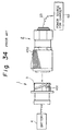
- FIG. 34 is a explanatory view of a conventional charge coupling.
- a vehicle inlet 1 is connected to a battery 4 and a supply connector 2 is connected through a flexible cable 23 to a charger 62.
- a distal end of the supply connector 2 is formed into shape suitable for fitting into an inlet housing or guide cylinder 3. When they are interconnected, terminals in the inlet 1 and connector 2 are interconnected to be electrically conducted.
- the inlet housing 3 is provided on its outer periphery with spiral grooves 451 and a rotatable sleeve 452 mounted on the distal end of the supply connector 2 is provided on its inner periphery with pins engageable with the spiral grooves 451.
- an operator Upon connecting the coupling, an operator holds the supply connector 2 with one hand so that the pins are engaged with the open ends of the spiral grooves 451 and rotates the sleeve 452 with his other hand. Then, the pins are guided by the spiral grooves 451 to advance the sleeve 452 and thus the supply connector 2 toward the vehicle inlet 1, thereby fitting the coupling.
- the sleeve 452 In order to engage the pins of the sleeve 452 with the spiral grooves 451 to connect the coupling, the sleeve must be rotated by about one turn not-withstanding a slippery surface of the sleeve 452. This extends work time and lowers efficiency.
- the outer periphery of the distal end of the supply connector is made of a metal material, it may injure a vehicle body if it contacts it by mistake.
- FIG. 35 is a longitudinal sectional view of a conventional vehicle inlet.
- an accommodating chamber 602 mounted on a vehicle body 200 is provided in its interior with a draining port 611. Water adhering to the interior of the chamber 602 flows down on the interior and is drained from the port 611 outside the chamber 602.
- an inner wall 604 and opposite side walls 608 standing vertically in the accommodating chamber 602 will allow water to drain.
- a first object of the present invention is to provide a charge coupling for an electric vehicle in which an incomplete fitting state of a supply connector a vehicle inlet can be easily detected.
- a second object of the present invention is to provide a charge coupling for an electric vehicle in which a flap lid of a vehicle inlet can be positively locked.
- a third object of the present invention is to provide a charge coupling for an electric vehicle which can prevent a fitting face from leaking a current and short circuiting due to water prior to fitting.
- a fourth object of the present invention is to provide a charge coupling for an electric vehicle which can positively position terminals.
- a fifth object of the present invention is to provide a charge coupling for an electric vehicle which can enhance a working operation and a working efficiency upon connecting.
- a sixth object of the present invention is to provide a charge coupling for an electric vehicle which can protect a vehicle body upon fitting a supply connector to a vehicle inlet and protect the supply connector from damage.
- a seventh object of the present invention is to provide a charge coupling for an electric vehicle which can prevent a vehicle inlet from leaking a current and short circuiting due to water upon connecting.
- a basic construction of a charge coupling for an electric vehicle in accordance with the present invention wherein conduction is enabled from a power source on the ground to a battery on the electric vehicle when a supply connector connected to said power source is completely fitted to a vehicle inlet installed in the electric vehicle, comprises: means for temporarily locking said supply connector to said vehicle inlet at a half fitting position.
- a charge coupling for an electric vehicle in accordance with the present invention further comprises: means for biasing said supply connector toward a returned position when said supply connector is inserted into said vehicle inlet, said locking means being adapted to temporarily maintaining said supply connector at said half fitting position when said supply connector is returned by said biasing means.
- Said locking means are provided on a lower and inner part of a housing of said vehicle inlet with a ridge extending axially. Said ridge is fitted in an engaging groove in said supply connector to guide said supply connector upon inserting said connector into said vehicle inlet. Said ridge is provided on its opposite longitudinal sides with guide slots which engage with plunger balls received in said supply connector. Said guide slots are provided with recesses in their middle portions which are disposed at said incomplete fitting position on which said supply connector is temporarily locked to said vehicle inlet.
- Said biasing means include a double cylindrical housing having an inner housing an outer housing and a compression coil spring disposed in a clearance between said inner and outer housing so that an end of said coil spring elastically contact with an opening edge of said vehicle inlet.
- the supply connector when the supply connector is completely fitted to the vehicle inlet, a conduction is allowed. However, if an inserting operation of the supply connector is stopped prior to the complete fitting position, the supply connector is returned by the biasing means and is temporarily maintained at the half fitting position by the locking means. Accordingly, if a complete fitting state is not obtained in the coupling, the supply connector is separated from the vehicle inlet to the half fitting position.
- the supply connector When the supply connector does not reach the complete fitting position, it is returned to the half fitting position and is not electrically connected to the vehicle inlet. An operator can easily determine that the supply connector has not reached the complete fitting position.
- the supply connector is returned to the half fitting position by the biasing means and is maintained at the half fitting position by the locking means, thereby preventing the supply connector from falling down from the vehicle inlet.
- a charge coupling for an electric vehicle in accordance with the present invention further comprises: a flap lid mechanism including a flap lid swingably mounted on an opening end of said vehicle inlet, an elastic member for biasing said flap lid toward an opened position, and means for latching said flap lid at a closed position on said opening end.
- the flap lid which is biased to the opened position by the elastic member is locked at the closed position on the opening end of the vehicle inlet by the latching means. Accordingly, the opening end of the vehicle inlet is positively sealed by the flap lid since the flap lid is locked at the complete closed position by the latching means after the flap lid is completely closed against the biasing force.
- the flap lid can preferably press a rubber packing on the opening end of the vehicle inlet, thereby maintaining the flap lid at the complete closed position under a state except charging.
- the flap lid is not left at a half opened position since the flap lid is biased to the opened position and must be closed by the operator.
- a charge coupling for an electric vehicle in accordance with the present invention said supply connector is provided on its fitting face an area between terminals with means for diverting water on said fitting face.
- Said diverting means is a recess or a ridge formed on said fitting face to section said area between said terminals.
- the diverting means is provided on the area between the terminals on the fitting face on the distal end of the vehicle inlet, even if rainwater adheres to the fitting face prior to fitting of the coupling upon charging, the diverting means increases a distance of a flow path of water between the adjacent terminals to shut off conduction due to water between the adjacent terminals. Consequently, it is possible to avoid leakage and short circuiting between the terminals.
- the recess or ridge for diverting water can be easily worked and increase the distance of the flow path of water between the adjacent terminals.
- the present invention when charging is carried out on a rainy day even if the fitting face of the vehicle inlet is wetted by rainwater prior to fitting of the coupling, it is possible to prevent leakage and short circuiting between the terminals prior to charging and during charging.
- the diverting means is a simple construction and can increase the distance of the flow path of water between the terminals, thereby easily realizing the water-diverting.
- a charge coupling for an electric vehicle in accordance with the present invention, a plurality of terminals having a circular cross section are inserted into a plurality of cavities having a circular cross section and provided in said inner housing of said supply connector, respectively, wherein said terminal is provided on its outer periphery with a plurality of lances so that said lances elastically contact with an inner periphery of said cavity to hold said terminal in said cavity coaxially, and wherein a positioning member is fitted in a connecting port of said cavity to be coupled to said vehicle inlet to enclose an end of said terminal.
- Each positioning member may be separately fitted in each cavity.
- a plurality of positioning means may be formed integrally.
- the distal end of the terminals is positioned by the positioning member, the distal end of the terminal is maintained at the coaxial position with the connection port of the cavity even if any external force perpendicular to the axis of the terminal, which is exerted by bending of the cable, is applied to the terminal.
- a terminal of a mating connector is fitted to the positioned distal end of the terminal.
- a plurality of positioning members may be attached to the connection port of each cavity.
- all members can be attached to all cavities simultaneously.
- the positioning member surely positions the distal end of the terminal at the coaxial position with the cavity, it is possible to avoid abutment of the terminal in the cavity and the mating terminal without fitting each other and to prevent a connection failure of the coupling and breakage of the terminals.
- the positioning members may be attached to each cavity. The integrated positioning members can enhance efficiency of attaching work.
- a charge coupling for an electric vehicle in accordance with the present invention said supply connector is connected to a charger through a charge cable and is provided coaxially in a connector housing with supply terminals.
- Said vehicle inlet is installed on a vehicle body of an electric vehicle and is provided coaxially in an inlet housing with terminals adapted to be coupled to said supply terminals.
- Said locking means are provided circumferentially on a distal end of either said vehicle inlet or said supply connector.
- Said locking means include a spiral groove which extends from a half fitting position of said supply connector relative to said vehicle inlet to a complete fitting position of said supply connector relative to said vehicle inlet and an engageable boss which projects from a distal end of the other one of said vehicle inlet and supply connector and is adapted to detachably engage with said spiral groove.
- Said supply connector is provided on its outer periphery with a handle which assists said supply connector in rotating so that said engageable boss moves in said spiral groove from a beginning end to a terminating end and vice versa.
- Holding means are provided on either said vehicle inlet or said supply connector and serve to maintain said supply connector at said complete fitting position in said vehicle inlet when said engageable boss reaches the terminating end of said spiral groove.
- an operator Upon fitting the coupling, an operator holds the handle by his one hand and engages the engageable boss with the beginning end of the spiral groove to bring the coupling into the half fitting state. Then the handle is rotated to turn the supply connector and to move the engageable boss in the spiral groove. When the engageable boss reaches the terminating end of the spiral groove, the supply connector is brought into the complete fitting position relative to the vehicle inlet.
- the terminals in the supply connector are arranged coaxially with the terminals in the vehicle inlet. Accordingly, both terminals are connected even if the supply connector is rotated relative to the vehicle inlet to displace the supply connector from the half fitting position to the complete fitting position.
- a charge coupling for an electric vehicle in accordance with the present invention an end of said supply connector is covered with a protective member.
- Said supply connector is provided on its outer periphery of the end with an engageable portion and said protective member is made of a rubber material and formed into a crown like shape to be mounted on said engageable portion.
- the protective member since the distal end of a metal shell of the supply connector is covered with the protective member, even if the distal end of the supply connector hits the vehicle body by mistake upon charging, the protective member absorbs a shock and prevent the metal shell from contacting with the vehicle body directly.
- a charge coupling for an electric vehicle in accordance with the present invention the electric vehicle is provided on its body with an accommodating chamber which is open outwardly to expose said vehicle inlet.
- Said accommodating chamber is provided on its interior with a draining mechanism including inclined walls.
- the interior of said accommodating chamber may be covered with a water-repelling layer.
- Said accommodating chamber may be provided on its interior with a water collection groove.
- Said accommodating chamber may be provided with a draining port in the vicinity of an opening edge.
- a cover attached to an opening of said accommodating chamber may be provided with a heater which heats the interior of the chamber.
- the accommodating chamber is provided on its interior with the water-repelling layer, water flows smoothly. Since the accommodating chamber is provided on its interior with the water collection groove, water on the interior will be collected in the groove without flowing on the vehicle inlet. Since the chamber is provided with the draining port in the vicinity of the opening edge, water does not flow out of the opening edge. Since the cover attached to the opening of the chamber is provided with the heater, heater heats the interior of the chamber, thereby evaporating water in the chamber.
- a charge coupling includes a vehicle inlet 1 and a supply connector 2.
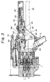
- the vehicle inlet 1 is provided with a cylindrical inlet housing 3 which accommodates charge terminals 5 connected to a battery 4 (see FIG. 3) in a vehicle and signal terminals 6 for detecting a charging condition.
- the inlet housing 3 is provided on a bracket 7 on a top face with a flap lid 8, which detachably covers an opening of the inlet housing 3 and seals an interior of the housing 3 by a seal ring 9 mounted on an inner face of the flap lid 8.
- a torsion spring 11 is mounted on a supply axle 10 to bias the flap lid 8 toward an opened position.
- the flap lid 8 is provided with a stopper (not shown) which limits an angular displacement of the flap lid 8 at an angle perpendicular to the inlet housing 3.
- the inlet housing 3 is provided on its lower portion with a jaw 3a having a hole 3b in a front end.
- a locking means 100 is received in the hole 3b.
- the locking means 100 includes a stopper member 14 which maintains the flap lid 8 at a closed position and an operation member 13 which releases the stopper member 14.
- the operation member 13 has an axle 13a slidably inserted in the hole 3b.
- the axle 13a is provided on its end with a flange 13b which serves to prevent the axle 13a from coming out of the hole 3b.
- a compression coil spring 12 is inserted in the hole 3b on the inner side from the flange 13b to bias the operation member 13 and the locking means outwardly.
- a pair of connecting pieces 13c extend from the flange 13b to a push disk 13d.
- the stopper member 14 is provided on its upper part with a pawl 14a which detachably engages with a pawl 15 of the flap lid 15.
- the stopper member 14 is received between the connecting pieces 13c and provided on opposite sides with bosses 17 which engage with cam slots formed in the connecting pieces 13c.
- the cam slots are formed so that the stopper member 14 is moved up or down by pushing the operation axle 13 or by returning the axle 13 by the spring 12.
- the jaw 3a is provided on its distal end with a guide slot 3c in which the stopper member 14 slides up and down.
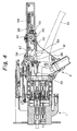
- the flap lid In the case of charging a battery in the vehicle, the flap lid is released to be open. That is, the operation member is pushed, the cam slot 18 lowers the boss 17, and the stopper member 14 releases the pawl 15. Then, the flap lid 8 is rotated in a direction shown by an arrow P in FIG. 5 since it is normally biased toward the open position by the torsion spring 11. The flap lid 8 is stopped at a position shown by solid lines in FIG. 5 by a stopper not shown. Since the opening of the inlet housing 3 is released, the supply connector not shown can approach the vehicle inlet to effect charging.
- the flap lid During non-charging, the flap lid is in the closed state. An external force is applied to the flap lid 8 against the biasing force of the torsion spring 11 to rotate the lid 8 in a direction shown by an arrow Q in FIG. 5.
- the flap lid 8 contacts with the opening edge of the inlet housing 3 to close it (shown by broken lines in FIG. 5)
- the pawl 15 of the flap lid 8 engages with pawls 14a of the stopper member 14, thereby locking the flap lid 8 at its closed position. It is possible to effect waterproofing, and dustproofing of the charging terminals 5 and signal terminals 6, since the opening of the inlet housing 3 is closed.
- the flap lid 8 which covers the opening of the inlet housing 3 of the vehicle inlet 1 can be positively held in the closed lid state by the locking means 100, thereby enhancing reliability of closing and holding the flap lid.
- the seal ring 7 for waterproofing disposed between the flap lid 8 and the inlet housing 3 can be surely pressed, the flap lid 8 can be always held in the closed lid state on a non-charging time, and waterproofing and dustproofing for the charge terminals 5 and signal terminals 6 accommodated in the inlet housing 3.
- the flap lid 8 Since the flap lid 8 is biased to the opening direction by the torsion spring 11, the flap lid 8 must be closed by an external force, thereby eliminating the problem of the flap lid 8 being left half open.
- the locking means 100 is actuated to open the flap lid 8 merely by pushing the push disk 13d of the operation member 13 and the flap lid 8 is closed by engaging the pawl 15 with the pawl 14a of the stopper member 14.
- the flap lid 8 can be very easily opened and closed, thereby enhancing an efficiency of work. Enabling the flap lid to be operated with one hand is particularly useful.
- the locking means 100 is provided on the inlet housing 3.
- the locking means may be provided on the flap lid 8 and the pawl may be provided on the inlet housing.
- the locking means 100 including the operation member 13 and stopper member 14 is used for locking the flap lid 8.
- Another locking and releasing mechanism may be used.
- FIG. 7 Another embodiment of a locking means for a flap lid in accordance with the present invention will be explained by referring to FIG. 7.
- the vehicle inlet 1 explained in the above embodiment is disposed in an accommodating chamber 201 provided in a vehicle body 200 of an electric vehicle.
- the accommodating chamber 201 is a recess formed in the vehicle body 200.
- a body lid 203 is rotatably attached to the chamber 201 through hinges 202.
- the body lid 203 is provided with a latch 204 which engages with the vehicle body 200 when the lid 203 is closed.
- the rotating direction of the flap lid 8 of the vehicle inlet 1 is substantially perpendicular to that of the body lid 203.
- the body lid 203 is opened upon charging. Then, the flap lid 8 is opened by actuating the locking means 100. On the non-charging time, the body lid 203 is closed after the flap lid 8 has been closed.
- the body lid 203 is not closed by the flap lid 8 when it is opened since the body lid 203 and flap lid 8 rotate in perpendicular to each other. Consequently, it is possible to detect a state leaving the flap lid 8 of the vehicle inlet 1 open, thereby enabling the flap lid 8 to be properly closed.
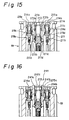
- the temporary locking mechanism are provided on a lower and inner part of the inlet housing 3 of the vehicle inlet 1 with a ridge 70 extending axially.
- the ridge 70 is fitted in an engaging groove 80 in the supply connector 2 to guide the supply connector 2 upon inserting the connector 2 into the vehicle inlet 1.
- the ridge 70 is provided on its opposite longitudinal sides with guide slots 74a and 74b which engage with plunger balls 84 received in the supply connector 2.
- the guide slots 74a and 74b are provided with recesses 72 in their middle portions which are disposed at the incomplete fitting position on which the supply connector 2 is temporarily locked to the vehicle inlet 1.
- the supply connector 2 will be explained below.
- the supply connector 2 is provided with a double cylindrical housing 19 including an inner housing 19a and an outer housing 19b.
- a compression coil spring 20 is disposed in a gap between the inner and outer housings 19a and 19b so that an outer end of the spring 20 detachably contacts with an opening edge on the vehicle inlet 1 to assist a separating action of the inlet 1 and connector 2.
- the spring 20 biases the supply connector 2 to a returned position when the supply connector 2 is inserted into the vehicle inlet 1. This biasing force to the returned position is applied to the supply connector 2 from the position in which the plunger balls 84 engages with the guide slots 74a.
- the outer housing 19b is provided on a lower side with the engaging groove 80 which engages with the ridge 70 axially (see FIG. 8).
- a tunnel 81 crosses vertically the engaging groove 80.
- Compression coil springs 82 are accommodated in the tunnel 81 so that each end of the spring 82 biases the plunger ball 84 toward the engaging groove 80.
- the plunger balls 84 which serve as the locking mechanism engage with the guide slots 74a and 74b in the ridge 70 to guide it when the supply connector 2 is inserted into the vehicle inlet 1.
- the plunger balls 84 engage with the recesses 72, the supply connector 2 is held at the temporary fitting position relative to the vehicle inlet 1.
- the inner housing 19a is provided in its interior with charge terminals and signal terminals, which are corresponding to the charging terminals 5 and signal terminals 6.
- the terminals are connected through a cable 23 to a power source on the ground.
- the outer housing 19b is provided on a top face with a flap lid 24 which detachably covers an opening of the outer housing 19b.
- the flap lid 24 is rotatably supported on a support pin 26 received in a bearing portion 25 formed on the top face of the outer housing 19b.
- a torsion spring 27 is mounted on the support pin 26 to bias the spring-back flap 24 toward a returned direction (a direction of closing the opening of the housing 19).
- a lock piece 28 is formed on a top face of a body 29 connected to a rear portion of the housing 19 to hold the flap lid 24 in an opened position.
- the lock piece 28 detachably engages with an edge 30 of the flap lid 24 at the distal end thereof and slides on the body 29 forwardly and rearwardly. Further, the lock piece 28 mounts a spring 31 on its rear portion so that the lock piece 28 is biased toward a direction of engaging with the flap lid 24 by the spring 31.
- the body 29 is provided on its rear portion with a grip shaft 32 which extends axially and is adapted to fit the housing 19 to the inlet housing 3 of the vehicle inlet 1.
- An operation lever 33 is rotatably attached to a proximal end of the grip shaft 32 through a rotary axle 34 to assist the supply connector 2 to be fitted to the vehicle inlet 1.
- a torsion spring 35 is mounted on the rotary axle 34 to bias the lever 33 to an opened position.
- a pair of stays 36 are coupled to the lever 33.
- a fitting-assist mechanism is constituted by the lever 33 and stays 36.
- the lever 33 is formed into an L-shaped body. The stays are coupled through a coupling pin 37 to a bent portion of the lever 33.
- each stay 36 is inserted into right and left sides in a gap between the inner housing 19a and the outer housing 19b.
- the stay 36 is provided on its distal end with an elongated slot 38 which receives each of bosses 39 projected on an outer face of the inlet housing 3 of the vehicle inlet 1 (see FIGS. 12A and 12B).
- a distance between the distal end of the stays 36 is widened under a normal condition as shown in FIG. 10A so that the slots 38 receive guide projections 40 formed on an inner wall of the outer housing 19b (see FIGS. 12A and 12B).
- the distal ends of the stays 36 are narrowed so that an end of the slot 38 engages with a ramp 41 of the guide projection 40, thereby closely contacting the stays 36 with the outer face of the vehicle inlet 1.
- the plunger balls 84 engage with the recesses 72 in the ridge 70, thereby temporarily locking the supply connector 2 relative to the vehicle inlet 1.
- the stays 36 are narrowed and the bosses 39 on the vehicle inlet 1 are fitted to the holes 38.
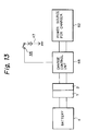
- the grip shaft 32 is provided on an upper face with a slide switch 42 which opens and closes a charging circuit described hereinafter by referring to FIG. 13.
- the slide switch 42 has a slide block 43 disposed in the grip shaft 32 and a push plate 45 secured to a bottom of the block 43 and extending toward a microswitch 44 which constitutes a part of the charging circuit.
- the slide switch 42 is driven to ON position (see FIGS. 2 and 11; a position shown by two dot chain lines in FIG. 2), the push plate 45 pushes a contact 46 of the microswitch 44.
- a charge control unit 48 (for example, a relay circuit) which controls opening and closing of the charging circuit is disposed between the supply connector 2 and a supply power source 47.
- the slide switch 42 is driven to the ON position (see FIGS. 2 and 11B; a position shown by the two dot chain lines in FIG. 2) to turn the microswitch 44 to ON, the microswitch 44 transmits an output signal through the supply power source 47 to the charge control unit 48.
- Conduction is enabled from a charger power source 62 to a vehicle battery 4 only when the microswitch 44 is closed and the conduction of charging current is inhibited when the microswitch 44 is opened.
- the slide switch 42 can be disposed at three positions such as ON position (FIGS. 2 and 11B; a position shown by the two dot chain lines in FIG. 2), OFF position (FIGS. 1, 2 and 11A), and returned position (FIGS. 3 and 11C).
- the slide switch is maintained at the ON and OFF positions by the following manner.
- the slide block 43 of the slide switch 42 is provided with a hole 49 extending diametrically.
- a compression coil spring 50 is accommodated in the hole 49 and balls 51 are disposed at the opposite ends of the spring 50 to elastically push the inner wall of the grip shaft 32.
- the grip shaft 32 is provided on its inner wall with recesses 52, which are arranged at positions corresponding to the ON and OFF positions.
- the slide switch 42 is maintained at the ON and OFF positions.
- a compression coil spring 53 is disposed between a rear side of the slide block 43 and a support wall in the grip shaft 32 to bias the slide switch 42 from the returned position to the OFF position.
- a spring force which pushes the balls 51 to the recesses 52 by the spring 50 is set to be stronger than that of the spring 53, the slide switch 53 cannot be displaced from the OFF position to the ON position only by the spring 53. If the operation applies a force more than a given force to the slide switch 42, the balls are released from the recesses 52.
- the slide switch 42 can not be driven to the ON position so long as the supply connector 2 is not completely set to the vehicle inlet 1 (the complete fitting position).
- a first stopper face 54 is defined by an edge of an end portion of the lever 33 in the vicinity of the rotary axle 34 and in opposition to an end of the push plate 45 of the slide switch 42. The slide switch 42 is inhibited from being actuated to the ON position before the lever 33 reaches the predetermined angular position.
- the grip shaft 32 is provided in its interior with a lever-lock plate 55 which extends axially and serves to maintain the lever 33 at the closed position.
- the lever-lock plate 55 is provided in its middle portion with an escape slot 56 which enables the slide block 43 to displace in the grip shaft 32 and on its end portion with a downward bent portion.
- the downward bent portion of the plate 55 is provided with an aperture 57 which receives and holds a part of the lever 33.
- the lever 33 is provided below the first stopper face 54 with a stepped portion.
- An edge portion 58 having the first stopper face 54 is detachably engaged with the aperture 57.
- the lever 33 is provided below the edge portion 58 with a stepped stopper face 61 which constrains the push plate 45 from advancing unless the lever 33 is moved to the complete fitting position.
- a compression coil spring 59 pushes a rear end of the lever-lock plate 55 to bias the plate 55 forwardly.
- the lever-lock plate 55 abuts on the first stopper face 55 under a normal condition to be constrained from advancing, as shown in FIG. 1 when the lever 33 is grasped to the complete fitting position so that the first stopper face 54 is opposite to the aperture 57, the edge portion 58 is inserted into the aperture 57 to hold the lever at the grasped position.
- An LED lamp 60 is lit when the charging circuit is turned to ON.
- the plunger balls 84 move on the ridge 70 while they engage with the guide slots 74a.
- the supply connector 2 is temporarily held against the biasing force of the compression coil spring 20 (see FIG. 8).
- the end of the elongated slot 38 engages with the ramp 41 of the guide projection 40 and the stays 36 are gradually deflected inwardly to receive the bosses 39 in the slots 38. If the operator continues to grasp the lever 33, the stays 36 are further retracted to exert a pulling force to the vehicle inlet 1.
- the supply connector 2 is pulled by a reaction of the vehicle inlet 1, thereby bringing the vehicle inlet 1 and supply connector 2 into the complete fitting position.
- the slide switch 42 causes the balls 51 to be fitted in the recesses 52 and the push plate 45 to abuts on the first stopper face 54 of the lever 33, thereby inhibiting the slide switch 42 from being driven to the ON position and avoiding miss-conduction.
- the lever-lock plate 55 abuts on the first stopper face 54 at its distal end to be constrained from advancing.
- the aperture 57 of the lever-lock plate 55 is adapted to receive the edge portion 58 of the lever 33 when the coupling reaches the complete fitting position, as shown in FIG. 2, the lever-lock plate 55 is advanced by the spring 59 and the edge portion 58 enters into the aperture 57. Thus, since the lever 33 is maintained in the grasped position the operator is released from continuing to grasp the lever 33.
- the second stopper face 61 is displaced to a higher position enough to enable the push plate 45 to advance.
- the slide switch 42 is driven from the OFF position to the ON position, the balls 51 are fitted in the recesses 52 in the ON position to maintain the slide switch 42 at the ON position.
- the slide switch 42 may be driven from the OFF position to the ON position (from the position shown in FIG. 1 to the position shown in FIG. 3) in connection with the lever 33 by increasing the biasing force of the spring 53 and turning the lever 33 to the complete fitting position. In this case, there is no need for a positioning mechanism including the spring 50, balls 51, and recesses 52.
- the push plate 45 pushes the contact 46 of the microswitch 44, and the charging control unit 48 closes the charging circuit, thereby conducting the battery in the vehicle.
- the microswitch 42 is retracted to the returned position (see FIG. 3). Then, the push plate 45 separates from the microswitch 44 to cease conduction to the charging circuit.
- the slide switch 42 is retracted to the returned position
- the lever-lock plate 55 is retracted to the returned position
- the lever-lock plate 55 is retracted against the spring 59. The edge portion 58 of the lever 33 comes out from the slot 57 and the lever 33 is automatically returned by the torsion spring 35.
- the supply connector 2 when the supply connector 2 is being drawn out of the vehicle inlet 1, the supply connector 2 is biased to the returning direction by the compression coil spring 20, the stays 36 return in reverse order while the stays are advancing, the plunger balls 84 return in the guide slots 74b, and the plunger balls 84 enter into the recesses 72 to temporarily hold the supply connector 2.
- the plunger balls 84 return in the guide slots 74a by the biasing force of the spring 20 and the ridge 70 separates from the engaging groove 80.
- the supply connector 2 in the case that the supply connector 2 is not brought into the complete fitting state, the supply connector 2 is pushed back to the temporary fitting position to hold it at this position. Consequently, the operator can detect that the coupling is not brought into the complete fitting state. Thus, the operator repeats the fitting operation.
- the supply connector 2 Since the supply connector 2 is held at the temporary fitting position, the supply connector 2 is prevented from falling from the vehicle inlet 1, thereby correcting the half fitting state of the coupling.
- conduction is enabled only after the terminals of the connector 2 and inlet 1 are completely interconnected and conduction is not enabled in the half fitting state, conduction due to a misoperation can be prevented.
- the terminals Since conduction is not enabled when the coupling is not in the complete fitting state, that is, the supply connector cannot move relative to the vehicle inlet, the terminals does not move during conduction. The terminals are protected from sparks.
- the lamp is kept to be lit during conduction, the operator can detect the charging state.
- the present invention may be altered in various forms.
- the lever 33 is provided with the stopper faces in this embodiment, they may be formed on another part so long as the stopper face inhibits the slide switch from being driven to the ON position under a normal condition and enables the driving of the switch upon detecting the complete fitting condition.
- the compression coil spring 20 is set to exert its biasing force from the time when the plunger balls 84 engage with the recesses.
- the spring 20 may be set to exert its biasing force immediately after the supply connector 2 is inserted into the vehicle inlet l. The biasing force may be exerted from the position in which the connector 2 is temporarily held in the vehicle inlet 1.
- the temporary fitting position is set to be a position in which the terminals in the inlet 1 and connector 2 begin to contact with each other in this embodiment.
- the temporary fitting position may be set to be anyplace regardless of the contact state of the terminals.
- the connector housing 19 of the supply connector 2 is provided on symmetrical positions on a fitting face 215a with power source terminals 212a and 212b, on a central lower position on the face with an earth terminal 213, and on the opposite sides of the earth terminal 213 and on a central upper position on the face with signal terminals 214a, 214b and 214c.
- the earth terminal 213 and signal terminals 214a, 214b and 214c are inserted into cavities 211b formed in a housing 211a.
- the terminals 213, 214a, 214b, and 214c are provided on their distal ends with metal latches 211c.
- the respective terminals 213, 214a 214b and 214c are prevented from coming out of the cavities 211b.
- the cavities 211b are provided on their interiors near the fitting face 215a with cylindrical guide bushes 211e.
- the distal ends of the terminals 213, 214a, 214b and 214c are inserted into the bushes to prevent plays in the cavities 211b.
- the power source terminals 212a and 212b are secured in the housing 211a by the same manner.
- a water-diverting groove 231 is formed in a terminal area around the earth terminal 213 on the fitting face 215a.
- the groove 231 is generally formed into a reversed U-shape including a left down part 231a which sections a terminal area between the earth terminal 213 and the signal terminal 214a, a horizontal part 231c which sections a terminal area between the earth terminal 213 and the power source terminals 212a and 212b, and a right down part 231b which sections a terminal area between the earth terminal 213 and the signal terminal 214b.
- the opposite ends of the horizontal part 231c are connected to each end of the left and right down parts 231a and 231b.
- the water-diverting groove 231 can prevent the water layer from spreading between the terminals.
- the flowing path between the terminals is increased by a simple construction, thereby realizing simple water-diverting.
- the water-diverting groove 231 is formed into a recess path in the above embodiment.
- a water-diverting ridge 241 formed in a reversed U-shape and having projections 241a, 241b and 241c may be provided in lieu of the recess path.
- the ridge 241 can also increase the flowing path between the terminals.
- the mating vehicle inlet is preferably provided on its fitting face with a reversed U-shape groove.
- the water-diverting groove 231 is formed in the reversed U-shape in the above embodiment.
- the groove 231 may be formed in any shape which can increase the flowing path between the terminals in accordance with an arrangement of the terminals.
- FIGS. 17 to 20 Next, an embodiment of a positioning member for a terminal will be explained below by referring to FIGS. 17 to 20.
- a general circular inner housing 19a of the supply connector 2 is provided in its interior with three kinds and six in total of cavities 302 which are formed into a circular shape in cross section each having different diameters and interior configurations.
- the cavities 302 extend axially in parallel with each other and are open at their opposite ends of the inner housing 19a.
- each cavity 302 is used as an insertion inlet 303 for receiving a terminal 310 described hereinafter while a front opening of each cavity 302 is used as a connection inlet 304 for receiving a terminal of a mating connector.
- the cavity 302 has an insertion space 305 and a connection space 306 which are formed into a circle in cross section and are disposed coaxially with each other.
- a ring like projecting stopper 307 is formed between the spaces 305 and 306 in the cavity 302.
- a reduced diameter hole 308 is formed coaxially between the spaces 305 and 306.
- a terminal 310 to be inserted into the cavity 302 is an elongated form having a circle in cross section.
- An outer diameter of the terminal 310 is slightly smaller than an inner diameter of the reduced diameter hole 308 of the cavity 302.
- the terminal 310 is provided on its end face with a fitting portion 311 to be coupled to a terminal of a mating connector not shown.
- a rear end of the terminal 310 is connected to an end of a cable 312 extending from a charging power source not shown.
- the terminal 310 is provided on its outer periphery with an attaching portion 313 having a slightly reduced diameter.
- a retainer 315 is mounted on the attaching portion 313 to hold the terminal 310 in the cavity 302.
- the retainer 315 is generally in a form of a tube which can be widened circumferentially in a C-shape by a longitudinal slit.
- the retainer 315 is provided at a plurality of peripheral positions with a plurality of lances 316 which project outwardly.
- the terminal 310 is provided on a rear position from the retainer 315 with a flange 317 having an outer diameter larger than the inner diameter of the hole 308.
- the distal end of the terminal 310 is inserted into the insertion inlet 303 of the cavity 302 from a rear side of the inner housing 19a.
- the retainer 315 passes through the hole 308 while elastically deforming the lances 316 inwardly.
- the lances 316 expand outwardly by means of their elastic recovery forces, so that the expanded ends elastically engage with the inner periphery of the connection space 306.
- the flange 317 of the terminal 310 abuts on a rear face of the projecting stopper 307 (peripheral edge of the hole 308) immediately after the lances 316 have expanded. Thus, the terminal 310 cannot come out of the cavity 302 and insertion of the terminal 310 is completed.
- the expanded ends of the lances 316 and the flange 317 engage with the front and rear end faces of the stopper 307, whereby the terminal 310 is positioned not to move longitudinally.
- the positioning means comprises a cylindrical cap 320 adapted to be fitted in the connection inlet 304 in the cavity 302.
- the cap 320 is provided on a side facing to the terminal 310 with a coaxial positioning bore 323 which has a diameter enough to loosely receive the fitting portion 311 of the terminal 310.
- the cap 320 is provided on its front side with a fitting bore 321 which is adapted to receive a terminal of the mating connector not shown and is communicated with the positioning bore 323.
- the fitting bore 321 is coaxial with the positioning bore 323 and has a smaller diameter than the bore 323. Further, the fitting bore 321 is provided on its opening edge with a beveled guide face 322 which enables the mating terminal not shown from being smoothly inserted.
- the cap 320 is secured to the connection inlet 304 of the cavity 302 by welding or pressing prior to inserting the terminal 310 into the cavity 302. After the cap 320 and terminal 310 are inserted into the cavity 302, the rear opening of the fitting bore 321 in the cap 320 is opposed to the front fitting end 11 of the terminal 310.
- the positioning bore 323 encloses the distal end of the terminal 310 with a slight clearance.
- the terminal 310 is likely to be inclined within a clearance between the lances 316 and the diameter-reduced hole 308 so that the lances 316 are elastically deformed. Since the distal end of the terminal 310 is inserted in the positioning bore 323 in the cap 320 with a little clearance, the distal end of the terminal 310 is not shifted out of the axis of the cavity 302. Accordingly, the terminal 310 is held coaxially in the cavity 302 and even if a deviation of center occurs between the terminal 310 and the cavity 302, an amount of the center deviation is so small that the mating terminal can properly enter into the terminal 310.
- the terminal 310 can be easily into the positioning bore 323.
- the fitting bore 321 is provided on its front end with the beveled guide face 322, the center deviation of the mating terminal is corrected toward the center of the fitting bore 321 by the beveled guide face 322 to smoothly insert the mating terminal into the fitting bore 321.
- the front fitting portion 311 of the terminal 310 is not exposed so that it is disposed in an inner side of the fitting bore 321 in the cap 320.
- the fitting portion 311 of the terminal 310 is not touched by the operator, thereby preventing an electrical shock to the operator.
- FIGS. 19 and 20 Another embodiment of the positioning means will be explained below by referring to FIGS. 19 and 20.
- a positioning means 330 for centering the distal end of the terminal 310 is constructed as follows.
- the positioning means 330 includes a disk base plate 331 and six pipes 332 standing on the rear side of the plate 331 at the positions corresponding to the cavities 302.
- Each pipe 332 has a fitting bore 333 with a beveled guide face 334 on the front side of the plate 331 and a positioning bore 335 which is opened at the rear end face of the pipe 332.
- each pipe 332 is inserted into the corresponding connection inlet 304 in the cavity 302.
- the rear side of the base plate 331 is closely contacted with the front side of the inner housing 19a and the contacting faces are welded.
- the positioning means 330 When the positioning means 330 is attached to the inner housing 19a, the rear opening of the fitting bore 333 is faced to the front fitting portion 311 of the terminal 310.
- the positioning bore 335 encloses the distal end of the terminal 310 with a slight clearance.
- the terminal 310 is held coaxially with the cavity 302 since a slight clearance is provided between the distal end of the terminal 310 and the positioning bore 335.
- FIGS. 21 to 27 Another embodiment of a temporary locking mechanism which temporarily locks a supply connector 2 at a temporary fitting position relative to a vehicle inlet 1 will be explained by referring to FIGS. 21 to 27.
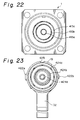
- the vehicle inlet 1 includes a guide cylindrical portion or an inlet housing 3 and a rectangular flange 412 formed integrally on the housing 3.
- the inlet housing 3 is provided coaxially at inner sides in the interior with power source terminals 413a and 413b and at an outer side in the interior with a signal terminal 413c.
- the power source terminals 413a and 413b are provided fully on the respective circles while the signal terminal 413c is spaced circumferentially on another circle.
- the inlet housing 3 is provided on its inner periphery with a pair of spiral grooves 414 which are formed substantially symmetrically relative to the axis from their beginning ends 414a to their terminating ends 414b.
- Engaging bosses 422 of the supply connector 2 to be described hereinafter move in the spiral grooves 414 to displace the supply connector 2 from a temporary fitting position to a complete fitting position relative to the vehicle inlet 1.
- the beginning ends 414a of the spiral groove 414 are open outwardly.
- the supply connector 2 When the bosses 422a and 422b are disposed in the terminating ends 414b of the spiral groove 414, the supply connector 2 is in a complete fitting state relative to the vehicle inlet 1.
- the inlet housing 3 is provided at an upper side on an inner periphery with a ridge 415 which positions the supply connector 2 upon fitting.
- the inlet housing 3 is provided in its interior with a pair of holding mechanisms 416 which are disposed symmetrically relative to the axis of the housing 3 to maintain the inlet 1 and connector 2 in the complete fitting state.
- the holding mechanisms 416 include a pair of tunnels 416a which are formed radially in an inner wall of the housing 3 to communicate with the interior of the housing 3, plunger balls 417 each of which is accommodated in each tunnel 416a, and compression coil springs 418 each of which biases the plunger ball 417 toward the inner periphery of the housing 3 in the tunnel 416.
- the plunger ball is smaller than an inner diameter of the tunnel 416a.
- An inner peripheral side opening 416b of the tunnel 416a is further reduced so that the plunger ball 417 does not come out of the tunnel 416a.
- the supply connector 2 is provided on its outer periphery with recesses which receive the plunger balls 417 when the connector 2 reaches the complete fitting position in the vehicle inlet 1.
- the supply connector 2 is provided coaxially in its interior with inner power source terminals 424a and 424b and an outer signal terminal 424c. These terminals are connected to the power source terminals 413a and 413b and signal terminals 413c in the vehicle inlet 1, respectively, when the supply connector 2 is fitted to the vehicle inlet 1.
- the inner power source terminals 424a and 424b are provided fully on the different circles while the outer signal terminals 424c is provided to be spaced on another circle.
- the signal terminals 424c in the supply connector 2 is disposed and spaced circumferentially from the signal terminals 413c in the vehicle inlet 1.
- the power souce terminals 424a and 424b are connected to the power source terminals 413a and 413b while the signal terminals 424c are not connected to the signal terminals 413c.
- the signal terminals 424c are connected to the signal terminals 413c.
- the charger detects the complete fitting state of the coupling from connection of the signal terminals 413c and 424c. Conduction from the power source terminals 424a and 424b to the power source terminals 413a and 413b are enabled by a security circuit.
- the cylindrical shell or connector housing 19 of the supply connector 2 is provided on an outer periphery symmetrically relative to the axis of the housing 19 with a pair of bosses 422a and 422b (see FIG. 23), which engage with the respective spiral grooves 414 in the inlet housing 3.
- a hand lever 32 extends from the lower portion of the housing 19 at the rear side from the bosses 422a and 422b.
- the supply connector 2 is fitted to the vehicle inlet 1 by operating the hand lever 32 by one hand of the operator.
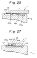
- the supply connector 2 is provided on its upper distal end with a slot 425 which receives a ridge 415 on an inner periphery of the housing 3.
- An elastically deformable piece 426 is disposed on an upper portion of the supply connector 2 at the rear side from the slot 425.
- the piece 426 is secured to the connector 2 at a base portion 426a which is disposed on a lower level than the bottom of the slot 425 and extends its free end rearwardly.
- An extending portion 426b continued to the base portion 426a is provided with a recess 426d which receives the ridge 415 when the coupling is in the half fitting state.
- This engagement of the ridge 415 in the recess 426d prevents the supply connector 2 from falling from the vehicle inlet by mistake in the half fitting state (see FIG. 25).
- the extending portion 426d is further continued to a pushing portion 426c.
- the pushing portion 426c is pressed down, the ridge 415 is released from the recess 426d.
- an escape groove 427 is provided on the outer periphery of the supply connector 2 in a spiral direction (not shown in detail in FIG. 26).
- the supply connector 2 is brought close the vehicle inlet 1 by handling the hand lever 32 with his one hand. Then, the ridge 415 moves onto the elastically deformable piece 426 and engages with the recess 426d, thereby holding the supply connector 2 at the half fitting state (see FIG. 25).
- the operator turns the supply connector 2 in a direction P relative to the vehicle inlet 1 in FIG. 21 with his one hand.
- the ridge 415 moves from the recess 426d into the escape groove 427 while the bosses 422a and 422b move from the beginning ends of the spiral grooves 414 toward the terminating ends 414b. Consequently, the supply connector 2 is completely fitted to the vehicle inlet 1.
- the holding mechanism 416 shown in FIG. 24 is actuated at the complete fitting position, so that the supply connector is fixed at the complete fitting position in the vehicle inlet 1.
- the respective terminals are interconnected electrically, even if the connector 2 is moved from the half fitting position to the complete fitting position.
- the power source terminals 424a and 424b of the supply connector 2 are connected to the power source terminals 413a and 413b of the vehicle inlet 1 and the signal terminals 424c and 413c are not interconnected.
- the signal terminals 424c and 413c are interconnected. Then, the charger detects the complete fitting state, thereby enabling conduction from the charger to the vehicle.
- the operator turns the hand lever 32 in the direction opposite to the direction P in FIG. 21 with one hand so as to rotate the supply connector 2 in the direction opposite to the direction upon connecting. Then, the bosses move from the terminating ends 414b of the spiral grooves 414 to the beginning ends 414a while the ridge 415 moves from the escape groove 427 to the slot 426d. Consequently, the coupling is brought from the complete fitting state to the half fitting state.
- the ridge 415 detaches from the supply connector 2 through the recess 426d, elastically deformable piece 426 and slot 425 while the bosses 422a and 422b come out of the beginning ends 414a of the spiral grooves 414.
- the supply connector 2 is disconnected from the vehicle inlet 1.
- a connecting process includes only fitting and turning steps of the hand lever 32 and does not require another step. Thus, a working time is shortened and efficiency is enhanced.
- the operator can detect from by touch that the coupling has reached the half fitting state when the ridge 415 engages with the recess 426d of the piece 426 and that the coupling reaches the complete fitting state when the bosses 422a and 422b displace from the beginning ends 414a of the spiral grooves 414 to the terminating ends 414b.
- spiral groove 414 is provided in the vehicle inlet 1 and the bosses 422a and 422b are provided on the supply connector 2. A contrary construction can be taken.
- the coupling is connected by engagement of the spiral grooves 414 and bosses 422a and 422b.
- the same effect can be obtained by various mechanisms such as a combination of a stationary spiral projection and a movable recess to be detachably engaged with the projection or a combination of a spiral cam groove and a rod.
- the holding mechanism 416 is provided in the vehicle inlet 1 in this embodiment.
- the mechanism 416 may be provided in the supply connector 2 or both inlet 1 and connector 2.
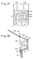
- a second elastically deformable piece 430 is provided with an engaging piece 431, and an engaging recess 432 is provided in an inner periphery of the housing 3, whereby these elements maintain the coupling in the complete fitting state by means of their mutual engagement in lieu of the holding mechanism 416 of the above-mentioned embodiment.
- the second elastically deformable piece 430 is provided on the supply connector 2 symmetrically relative to the axis of the connector 2 near the piece 426.
- the second elastically deformable piece 430 is a cantilever type construction in which a proximal end 430a is fixed on the connector 2 and a free end 430b extends rearwardly.
- the second piece 430 is provided on its middle portion with an engaging piece 431 which projects from the upper face by a given height.
- the engaging piece 431 is provided on its front side with a guide ramp 431a.
- the supply connector 2 is smoothly inserted into the vehicle inlet 1 through the guide ramp 431a.
- the second piece 430 is provided on a lower side with an escape recess 433 in which the second piece enters when being deformed.
- the engaging piece 431 of the second piece 430 is pressed on an inner periphery of a guide barrel 411, whereby the second piece is deflected to enter into the escape recess 433 (shown by two dot chain lines in FIG. 27).
- the engaging piece 431 reaches an engaging recess 432 while moving spirally on the inner periphery of the guide barrel 411. Consequently, the engaging piece 431 engages with the recess 432 and the second piece 430 elastically recovers (shown by solid lines in FIG. 27).
- the coupling is held in the complete fitting state by means of engagement of the piece 431 and recess 432.
- a combination of the engaging piece 431 of the second piece 430 and the engaging recess 432 in the inner periphery of the housing 3 can maintain the coupling in the complete fitting state.
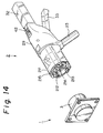
- a protective member for a connector end will be explained below by referring to FIGS. 28 to 30.
- a coupling comprises a vehicle inlet 1 and a supply connector 2.
- the vehicle inlet 1 includes a cylindrical metal guide or inlet housing 3 and a plate like flange provided on a rear side of the housing 3.
- the vehicle inlet 1 is secured to an electric vehicle not shown by fixing the flange on a vehicle body not shown.
- the housing 3 is provided in its interior with a male connector unit including power source terminals and a signal terminal.
- the supply connector 2 includes a metal shell (for example, made of aluminium or the like) or outer housing 19b.
- the outer housing 19b is provided in its interior with a female connector unit 514 having power source terminals 512 and signal terminals 513 which correspond to the respective terminals in the vehicle inlet 1.
- the female connector unit 514 is connected through a cable 23 to a power source and a charging device.
- a body 29 extends from a rear portion of the outer housing 19b and a grip handle 32 extends axially from a rear portion of the body 29.
- the grip handle 32 is used to fit the connector 2 to the inlet 1.
- a lever 33 is rotatably attached to a proximal end of the grip handle 32 to enable the supply connector 2 to be easily fitted to the vehicle inlet 1.
- the body 29 is provided on its upper face with a slide switch 42 which opens and closes a charging circuit not shown.
- a ring rubber cover 530 is mounted On an outer periphery end of the outer housing 19b so that the cover 530 shields the whole end periphery of the housing 19b.
- the outer housing 19b is provided on an outer periphery near an distal end edge 511a with an annular ridge 532 on which the cover 530 is mounted.
- the annular ridge is formed into a T-shape in cross section.
- the rubber cover 530 is provided on its inner periphery with a groove 534 which is formed into a complementary T-shape in cross section. When the groove 534 engages with the annular ridge 532, the rubber cover 530 is secured to the outer housing 19b.
- the outer housing 19b is provided in the inner periphery with an annular shoulder 536 which defines an insertion portion 538 with a thinner thickness than the housing 19b.
- the rubber cover 530 is provided with an annular groove 540 adapted to receive the insertion portion 538. When the insertion portion 538 is inserted into the annular groove 540, the distal end edge 511a of the outer housing 19b is shielded with the cover 530.
- the annular groove 540 in the cover 530 fits on the insertion portion 538 of the housing 19b, and the groove 534 in the cover 530 fits on the ridge 532 of the housing 19b while the cover 530 is being extended rearwardly, thereby fixing the rubber cover 530 on the housing 19b. Consequently, the outer periphery, end edge 511a and the inner periphery of the insertion portion 538 are all shielded by the cover 530.
- the outer housing 19b shielded with the cover 530 is fitted on the inlet housing 3 of the vehicle inlet 1 to push the supply connector 2 onto the vehicle inlet 1.
- an inner periphery 530e of the rubber cover 530 and the inner periphery of the housing 19b contact with the outer periphery of the inlet housing 3 and the male connector unit not shown is coupled to the female connector unit 514.
- the inlet 1 and connector 2 are interconnected.
- the housing 19b even if the housing 19b contacts with the body by mistake when the supply connector 2 is fitted to the vehicle inlet 1 upon charging, the housing 19 does not injure the body since the cover 530 directly contacts with the body.
- the cover 530 is positively secured to the housing 19b without using a special fixing member such as a ring or the like. Accordingly, the construction is simplified.
- the rubber cover can be easily attached to and detached from the housing 19b. This makes exchange or maintenance of the rubber cover easy.
- the rubber cover may shield only the outer periphery and end edge of the housing 19b.
- the rubber cover may be secured on the housing by means of adhesion or welding.
- FIGS. 31 and 32 Next, an embodiment of a draining mechanism of the present invention will be explained by referring to FIGS. 31 and 32.
- a body 200 of an electric vehicle is provided with a rectangular accommodating chamber 602 which is open outwardly.
- the chamber 602 is provided on its opening with a rocking cover 603.
- a vehicle inlet 1 is accommodated in the chamber 602, with the inlet projecting from a vertical inner wall 604.
- a supply connector not shown is connected to the vehicle inlet 1 to charge a battery not shown in the vehicle.
- a ceiling wall 606 of the chamber 602 is inclined downwardly from the opening to the inner wall 604.
- a floor wall 607 is inclined upwardly from the opening to the inner wall 604 and downwardly from opposite side walls 608 and 608 to a central portion.
- the accommodating chamber 602 is provided with water-collecting grooves 609 on the connected edge portions between the ceiling wall 606 and the inner wall 604, between the inner wall 604 and the opposite side walls 608, 608, and between the floor wall 607 and the inner wall 604.
- the water-collecting grooves 609 are communicated with a draining groove 610 extending in a central lower valley on the floor wall 607.
- the draining groove 610 is communicated with a draining port 611 formed in the floor wall 607 near the opening of the chamber 602.
- a hose 612 is connected to the draining port 611 with a lower end of the hose 612 being disposed out of the body.
- a water-repelling treatment such as Teflon (trade name) coating or the like may be applied to surfaces of the inner wall 604, ceiling wall 606, floor wall 607, side walls 608, collecting grooves 609, and draining groove 610.
- the cover 203 attached to the opening of the accommodating chamber 602 is provided on its inner face with a heating means such as a heating wire.
- Water on the vertical inner wall 604 flows down by means of the water-repelling treatment and reaches the collecting grooves 609.
- the water in the grooves 609 is drained through the draining groove 610, draining port 611 and hose 612 to the outside of the chamber 602.
- the heating means may be omitted.
- only water on the upper face of the vehicle inlet 1 tends to moisten the terminals.
- such water is very small in amount and a great part of water is drained out of the chamber 602 without wetting the terminals. Accordingly, there is little danger of leakage and short-circuiting due to wetting of the vehicle inlet 1.
- the drained water does not flow on an exterior of the body 200 through the opening of the chamber 602. Accordingly, water flown out of the chamber 602 does not spoil the appearance of the vehicle body.
Landscapes
- Engineering & Computer Science (AREA)
- Power Engineering (AREA)
- Transportation (AREA)
- Mechanical Engineering (AREA)
- Electric Propulsion And Braking For Vehicles (AREA)
- Details Of Connecting Devices For Male And Female Coupling (AREA)
- Connector Housings Or Holding Contact Members (AREA)
Applications Claiming Priority (22)
| Application Number | Priority Date | Filing Date | Title |
|---|---|---|---|
| JP19544393A JPH0729631A (ja) | 1993-07-12 | 1993-07-12 | 電気自動車の充電用コネクタ回りの排水構造 |
| JP19544393 | 1993-07-12 | ||
| JP195443/93 | 1993-07-12 | ||
| JP197862/93 | 1993-07-14 | ||
| JP19786293 | 1993-07-14 | ||
| JP5197862A JP3013662B2 (ja) | 1993-07-14 | 1993-07-14 | 電気自動車充電用コネクタ |
| JP19895793 | 1993-07-15 | ||
| JP198957/93 | 1993-07-15 | ||
| JP19895793A JPH0729635A (ja) | 1993-07-15 | 1993-07-15 | 電気自動車用コネクタ |
| JP5226472A JPH0757814A (ja) | 1993-08-18 | 1993-08-18 | 電気自動車用充電コネクタ |
| JP226472/93 | 1993-08-18 | ||
| JP22647293 | 1993-08-18 | ||
| JP228038/93 | 1993-08-20 | ||
| JP22803893 | 1993-08-20 | ||
| JP22803893A JPH0765891A (ja) | 1993-08-20 | 1993-08-20 | 電気自動車用充電コネクタ |
| JP24044793 | 1993-08-31 | ||
| JP240447/93 | 1993-08-31 | ||
| JP5240447A JP2972503B2 (ja) | 1993-06-14 | 1993-08-31 | 電気自動車のチャージ用コネクタ |
| JP25765093 | 1993-09-20 | ||
| JP257650/93 | 1993-09-20 | ||
| JP25765093A JP2985606B2 (ja) | 1993-09-20 | 1993-09-20 | コネクタ |
| EP94305084A EP0634818B1 (de) | 1993-07-12 | 1994-07-12 | Ladekupplung für elektrische Fahrzeuge |
Related Parent Applications (1)
| Application Number | Title | Priority Date | Filing Date |
|---|---|---|---|
| EP94305084A Division EP0634818B1 (de) | 1993-07-12 | 1994-07-12 | Ladekupplung für elektrische Fahrzeuge |
Publications (2)
| Publication Number | Publication Date |
|---|---|
| EP0843388A2 true EP0843388A2 (de) | 1998-05-20 |
| EP0843388A3 EP0843388A3 (de) | 1999-10-20 |
Family
ID=27566473
Family Applications (2)
| Application Number | Title | Priority Date | Filing Date |
|---|---|---|---|
| EP98102268A Ceased EP0843388A3 (de) | 1993-07-12 | 1994-07-12 | Ladekupplung für elektrische Fahrzeuge |
| EP94305084A Expired - Lifetime EP0634818B1 (de) | 1993-07-12 | 1994-07-12 | Ladekupplung für elektrische Fahrzeuge |
Family Applications After (1)
| Application Number | Title | Priority Date | Filing Date |
|---|---|---|---|
| EP94305084A Expired - Lifetime EP0634818B1 (de) | 1993-07-12 | 1994-07-12 | Ladekupplung für elektrische Fahrzeuge |
Country Status (3)
| Country | Link |
|---|---|
| US (4) | US5458496A (de) |
| EP (2) | EP0843388A3 (de) |
| DE (1) | DE69422231T2 (de) |
Cited By (7)
| Publication number | Priority date | Publication date | Assignee | Title |
|---|---|---|---|---|
| CN107662519A (zh) * | 2017-09-21 | 2018-02-06 | 骆剑锋 | 一种新能源汽车装置 |
| CN107804186A (zh) * | 2017-10-30 | 2018-03-16 | 朱灵龙 | 一种新能源汽车充电设备 |
| CN108199223A (zh) * | 2017-12-25 | 2018-06-22 | 广州大正机械科技开发有限公司 | 一种新能源充电桩装置 |
| CN108215824A (zh) * | 2017-07-14 | 2018-06-29 | 广州航爵数码科技有限公司 | 一种便捷的新能源汽车充电桩结构 |
| CN108466565A (zh) * | 2018-03-21 | 2018-08-31 | 王和能 | 一种耦合式充电桩对新能源汽车的快速充电方法 |
| CN111409492A (zh) * | 2020-05-07 | 2020-07-14 | 九江职业技术学院 | 一种新能源汽车充电保护装置 |
| CN117559609A (zh) * | 2024-01-10 | 2024-02-13 | 深圳市鸿锡科技有限公司 | 一种低功耗充电的充电器 |
Families Citing this family (145)
| Publication number | Priority date | Publication date | Assignee | Title |
|---|---|---|---|---|
| US5458496A (en) * | 1993-07-12 | 1995-10-17 | Sumitomo Wiring Systems, Ltd. | Charge coupling for electric vehicle |
| JP3463820B2 (ja) * | 1994-04-01 | 2003-11-05 | 矢崎総業株式会社 | 給電コネクタ |
| JP2904024B2 (ja) * | 1994-08-08 | 1999-06-14 | 住友電装株式会社 | 電気自動車のチャージ用コネクタ |
| JP3135040B2 (ja) * | 1995-11-30 | 2001-02-13 | 矢崎総業株式会社 | 電気自動車の充電用コネクタ |
| JP3292278B2 (ja) * | 1995-12-06 | 2002-06-17 | 矢崎総業株式会社 | 電気自動車の充電用コネクタ |
| EP0886905A4 (de) * | 1996-01-16 | 2000-12-20 | Electro Dynamics Inc | Kapazitive ladungskoppelung mit doppelten verbindungsgruppen und ladesystem |
| FR2769458B1 (fr) * | 1997-10-08 | 1999-12-24 | Meritor Light Vehicle Sys Ltd | Systeme de raccordement d'un moteur electrique d'activation d'un organe fonctionnel de vehicule automobile |
| US6203355B1 (en) | 1998-03-31 | 2001-03-20 | Daimlerchrysler Corporation | Universal charge port connector for electric vehicles |
| US6371768B1 (en) | 1998-03-31 | 2002-04-16 | Daimlerchrysler Corporation | Universal charge port connector for electric vehicles |
| US6225153B1 (en) | 1999-03-24 | 2001-05-01 | Daimlerchrysler Corporation | Universal charge port connector for electric vehicles |
| FR2795687B1 (fr) * | 1999-06-29 | 2001-09-28 | Martine Losego | Dispositif de connexion automatique de chargeur de batteries embarque sur chariot ou petit vehicule a traction electrique |
| US6091223A (en) * | 1999-08-11 | 2000-07-18 | Electric Vehicle Infrastructure, Inc. | Contactor monitor for charging stations |
| JP3731797B2 (ja) * | 1999-11-08 | 2006-01-05 | 矢崎総業株式会社 | 給電コネクタ |
| JP2002112435A (ja) * | 2000-09-27 | 2002-04-12 | Sumitomo Wiring Syst Ltd | 高電圧用電気接続箱 |
| JP3866052B2 (ja) * | 2001-05-24 | 2007-01-10 | 矢崎総業株式会社 | 給電コネクタ |
| DE10131191A1 (de) * | 2001-06-28 | 2003-01-09 | Delphi Tech Inc | Elektrischer Verbinder |
| US6709274B2 (en) * | 2001-08-07 | 2004-03-23 | The Boeing Company | Aircraft high performance external fixed and ground supply free plug connectors and its assembly |
| TW540890U (en) * | 2001-08-24 | 2003-07-01 | Hon Hai Prec Ind Co Ltd | Cable connector assembly |
| US20040080186A1 (en) * | 2002-09-09 | 2004-04-29 | Jean-Phillipe Crepeau | Service center for a recreational vehicle |
| US6994560B2 (en) * | 2003-12-19 | 2006-02-07 | Institute For Home Economics Of Japan, Inc. | External power source connecting device for an electric vehicle |
| DE102004038680A1 (de) * | 2004-08-10 | 2006-02-23 | Jungheinrich Aktiengesellschaft | Ladegerät für Batterie mit Ladekabel |
| DE202004015502U1 (de) * | 2004-10-06 | 2004-12-30 | Rosenberger Hochfrequenztechnik Gmbh & Co. Kg | Koaxialsteckverbinder mit Schnellverschluß |
| GB0516907D0 (en) * | 2005-08-18 | 2005-09-28 | Earlex Ltd | Connector cover |
| US7859219B2 (en) | 2007-02-07 | 2010-12-28 | David M Harris | Disconnect for a charging unit for an electric vehicle |
| JP5105170B2 (ja) * | 2008-01-17 | 2012-12-19 | 住友電装株式会社 | コネクタ |
| JP4371167B2 (ja) * | 2008-03-31 | 2009-11-25 | 三菱自動車工業株式会社 | 車両の接続用コードの支持構造 |
| JP5044508B2 (ja) * | 2008-08-26 | 2012-10-10 | 矢崎総業株式会社 | コネクタ |
| US7677631B1 (en) * | 2008-11-14 | 2010-03-16 | Nissan Technical Center North America, Inc. | Vehicle access assembly |
| JP5312214B2 (ja) * | 2009-06-11 | 2013-10-09 | 矢崎総業株式会社 | 誤操作防止機構付きレバー式電気コネクタ |
| WO2010150359A1 (ja) | 2009-06-24 | 2010-12-29 | トヨタ自動車株式会社 | 充電ケーブルおよび電動車両の充電システム |
| US7963793B2 (en) * | 2009-09-24 | 2011-06-21 | Lear Corporation | Hybrid/electric vehicle charge handle latch mechanism |
| WO2011038056A1 (en) * | 2009-09-28 | 2011-03-31 | Powerhydrant Llc | Method and system for charging electric vehicles |
| US8535088B2 (en) | 2009-10-20 | 2013-09-17 | Apple Inc. | Magnetic connector having a unitary housing |
| DE202009013675U1 (de) * | 2009-11-04 | 2011-03-17 | Rema Lipprandt Gmbh & Co. Kg | Ladestecksystem |
| DE102009052870B4 (de) * | 2009-11-13 | 2020-09-03 | Sew-Eurodrive Gmbh & Co Kg | Anordnung zum Anschließen eines Fahrzeugs |
| US8016607B2 (en) * | 2010-01-08 | 2011-09-13 | Lear Corporation | Connector assembly for electric vehicle charging |
| JP5482295B2 (ja) * | 2010-03-01 | 2014-05-07 | 住友電装株式会社 | 充電用コネクタ |
| JP5447962B2 (ja) * | 2010-02-19 | 2014-03-19 | 住友電装株式会社 | 充電用コネクタ |
| JP5312370B2 (ja) * | 2010-02-23 | 2013-10-09 | トヨタ自動車株式会社 | インレット組立体 |
| JP5504987B2 (ja) * | 2010-03-11 | 2014-05-28 | 住友電装株式会社 | 充電用コネクタ |
| US8841881B2 (en) | 2010-06-02 | 2014-09-23 | Bryan Marc Failing | Energy transfer with vehicles |
| US8075329B1 (en) * | 2010-06-08 | 2011-12-13 | Ford Global Technologies, Llc | Method and system for preventing disengagement between an electrical plug and a charge port on an electric vehicle |
| JP5524725B2 (ja) * | 2010-06-08 | 2014-06-18 | 株式会社東海理化電機製作所 | 給電プラグのロック装置 |
| JP5471890B2 (ja) * | 2010-06-28 | 2014-04-16 | 住友電装株式会社 | 充電用コネクタ |
| US8342893B2 (en) | 2010-07-02 | 2013-01-01 | Lear Corporation | Stamped electrical terminal |
| US7878866B1 (en) | 2010-07-02 | 2011-02-01 | Lear Corporation | Connector assembly for vehicle charging |
| DE102010032313B4 (de) * | 2010-07-27 | 2023-12-07 | Volkswagen Ag | Gehäuse, Steckkontaktverbindung und Verfahren zur elektrischen Kontaktierung |
| JP5890091B2 (ja) * | 2010-10-29 | 2016-03-22 | 日本航空電子工業株式会社 | 電気コネクタ、電気コネクタユニット、及び電気自動車用充電器 |
| JP5739644B2 (ja) * | 2010-11-02 | 2015-06-24 | 矢崎総業株式会社 | 給電コネクタ |
| US20120126747A1 (en) * | 2010-11-19 | 2012-05-24 | Delphi Technologies, Inc. | Battery charger having non-contact electrical switch |
| US20120129378A1 (en) * | 2010-11-19 | 2012-05-24 | Delphi Technologies, Inc. | Battery charger having handle that includes light source that emits light through aperture in handle connector |
| KR101180956B1 (ko) * | 2010-12-02 | 2012-09-07 | 기아자동차주식회사 | 전기 차량의 충전기 도난 방지 장치 |
| US8568155B2 (en) | 2010-12-30 | 2013-10-29 | General Cable Technologies Corporation | Laminous multi-polymeric high amperage over-molded connector assembly for plug-in hybrid electric vehicle charging |
| US8562365B2 (en) | 2010-12-30 | 2013-10-22 | General Cable Technologies Corporation | Laminous multi-polymeric high amperage over-molded connector assembly for plug-in hybrid electric vehicle charging |
| US8729856B2 (en) * | 2011-02-23 | 2014-05-20 | Lear Corporation | Thermal wall plug sensing and control |
| FR2972145B1 (fr) * | 2011-03-01 | 2013-04-26 | Peugeot Citroen Automobiles Sa | Trappe de prise de charge pour vehicule electrique et vehicule equipe d'une telle trappe. |
| US8712648B2 (en) * | 2011-03-08 | 2014-04-29 | Gm Global Technology Operations | Passive charge cord release system for an electric vehicle |
| JP5679191B2 (ja) | 2011-04-05 | 2015-03-04 | 住友電装株式会社 | 車両側コネクタ |
| US8668506B2 (en) * | 2011-04-27 | 2014-03-11 | Lear Corporation | Charger receptacle |
| US8876562B2 (en) | 2011-05-05 | 2014-11-04 | Lear Corporation | Female type contact for an electrical connector |
| US8840436B2 (en) | 2011-05-05 | 2014-09-23 | Lear Corporation | Electrically conducting terminal |
| US9325095B2 (en) | 2011-05-05 | 2016-04-26 | Lear Corporation | Female type contact for an electrical connector |
| JP5582093B2 (ja) | 2011-05-17 | 2014-09-03 | 住友電装株式会社 | 車両側コネクタ |
| DE102011052078A1 (de) | 2011-07-22 | 2013-01-24 | Dr. Ing. H.C. F. Porsche Aktiengesellschaft | Ladekupplung und Ladekupplungsanordnung für ein Kraftfahrzeug sowie Kraftfahrzeug |
| GB201113338D0 (en) * | 2011-08-03 | 2011-09-14 | Rota Eng Ltd | Connector |
| US8808039B2 (en) | 2011-08-22 | 2014-08-19 | Lear Corporation | Connector assembly and terminal retainer |
| GB201116284D0 (en) * | 2011-09-21 | 2011-11-02 | Delphi Tech Inc | Electrical connector with drainage system |
| US8651875B2 (en) * | 2011-09-28 | 2014-02-18 | Tesla Motors, Inc. | Electromechanical pawl for controlling vehicle charge inlet access |
| US8720968B2 (en) | 2011-09-28 | 2014-05-13 | Tesla Motors, Inc. | Charge port door with electromagnetic latching assembly |
| US8579635B2 (en) * | 2011-09-28 | 2013-11-12 | Tesla Motors, Inc. | Funnel shaped charge inlet |
| PL2763878T3 (pl) * | 2011-10-03 | 2021-03-08 | Husqvarna Ab | Zasilany akumulatorowo pojazd z unieruchamiającą wtyczką ładowarki |
| US8550833B2 (en) | 2011-10-07 | 2013-10-08 | Ford Global Technologies, Llc | Locking apparatus for electric vehicle charging connector |
| JP5813462B2 (ja) * | 2011-10-31 | 2015-11-17 | 矢崎総業株式会社 | コネクタ嵌合構造 |
| KR101803579B1 (ko) | 2011-11-17 | 2017-11-30 | 엘에스전선 주식회사 | 전기자동차 충전장치의 커넥터 |
| DE102012100235B4 (de) * | 2012-01-12 | 2015-12-24 | Phoenix Contact Gmbh & Co. Kg | Kabelstecker mit Abdeckeinrichtung |
| JP5917918B2 (ja) * | 2012-01-16 | 2016-05-18 | 日産自動車株式会社 | 給電コネクタ |
| JP5815425B2 (ja) * | 2012-01-17 | 2015-11-17 | 矢崎総業株式会社 | 電気コネクタ |
| JP5798935B2 (ja) * | 2012-01-17 | 2015-10-21 | 矢崎総業株式会社 | 電気コネクタ |
| JP5815423B2 (ja) * | 2012-01-17 | 2015-11-17 | 矢崎総業株式会社 | 電気コネクタ |
| CN102529727A (zh) * | 2012-02-11 | 2012-07-04 | 江苏金彭车业有限公司 | 一种电动车充电保护装置 |
| GB2500012B (en) | 2012-03-06 | 2016-07-06 | Dyson Technology Ltd | A Humidifying Apparatus |
| GB2500005B (en) | 2012-03-06 | 2014-08-27 | Dyson Technology Ltd | A method of generating a humid air flow |
| GB2500017B (en) | 2012-03-06 | 2015-07-29 | Dyson Technology Ltd | A Humidifying Apparatus |
| JP5939927B2 (ja) * | 2012-08-06 | 2016-06-22 | 矢崎総業株式会社 | 充電コネクタ |
| US9187290B2 (en) | 2012-09-14 | 2015-11-17 | Lear Corporation | Cordset assembly |
| CN104640737B (zh) * | 2012-09-19 | 2018-10-16 | 日产自动车株式会社 | 电动车辆的外部充电构造 |
| JP5981294B2 (ja) * | 2012-10-12 | 2016-08-31 | 矢崎総業株式会社 | 充電インレット装置 |
| US9252539B2 (en) | 2012-11-02 | 2016-02-02 | Hubbell Incorporated | Internally switched female receptacle or connector with plug-latching safety interlock |
| US8858264B2 (en) | 2012-11-28 | 2014-10-14 | Lear Corporation | Electrical terminal retainer and receptacle assembly |
| DE102012024588B4 (de) * | 2012-12-17 | 2023-11-16 | HARTING Automotive GmbH | Steckverbinder |
| EP3093575B1 (de) | 2013-01-29 | 2018-05-09 | Dyson Technology Limited | Gebläseanordnung |
| US9543713B2 (en) * | 2013-03-19 | 2017-01-10 | Sumitomo Wiring Systems, Ltd. | Vehicle-side connector with a relay-circuit unit |
| DE102014003565A1 (de) * | 2013-03-19 | 2014-09-25 | Sumitomo Wiring Systems, Ltd. | Fahrzeugseitiger Verbinder und Verfahren zum Zusammenbauen desselben |
| WO2014147763A1 (ja) | 2013-03-19 | 2014-09-25 | 住友電装株式会社 | 車両側コネクタ |
| EP2980926B1 (de) * | 2013-03-28 | 2017-11-01 | Yazaki Corporation | Ladestecker |
| JP5965349B2 (ja) * | 2013-04-17 | 2016-08-03 | 株式会社城南製作所 | 自動車のエネルギー受給口装置 |
| DE102013213336B4 (de) * | 2013-07-08 | 2024-02-01 | Te Connectivity Germany Gmbh | Elektrischer steckverbinder, ladedose und steckverbindersystem für ein elektro- oder hybridfahrzeug |
| US9493087B2 (en) | 2013-08-07 | 2016-11-15 | Powerhydrant Llc | Method and system for automatic charging of electric vehicles |
| DE102013110547B4 (de) * | 2013-09-24 | 2020-02-06 | Phoenix Contact E-Mobility Gmbh | Steckverbinderteil mit einer Entwässerung |
| JP6148964B2 (ja) * | 2013-10-17 | 2017-06-14 | 日本航空電子工業株式会社 | コネクタ |
| JP2015082340A (ja) | 2013-10-21 | 2015-04-27 | 矢崎総業株式会社 | 充電コネクタ |
| US9185987B1 (en) | 2014-05-06 | 2015-11-17 | Patrick Nugent | Adaptable seat caddy |
| US9653842B2 (en) * | 2014-05-09 | 2017-05-16 | Textron Inc. | Water resistant USB connection system for vehicles |
| JP2015225771A (ja) * | 2014-05-28 | 2015-12-14 | 住友電装株式会社 | 複合型充電用インレット |
| US9899821B2 (en) | 2014-06-24 | 2018-02-20 | Lear Corporation | Cordset assembly |
| GB2528708B (en) * | 2014-07-29 | 2016-06-29 | Dyson Technology Ltd | A fan assembly |
| US9293860B1 (en) * | 2014-09-22 | 2016-03-22 | Hyundai Motor Company | Connector for a vehicle |
| DE102014015148B4 (de) * | 2014-10-13 | 2018-11-29 | Sumitomo Wiring Systems, Ltd. | Ladeverbinder und Verfahren zum Montieren desselben |
| US9385475B1 (en) | 2015-02-06 | 2016-07-05 | Cooper Technologies Company | Indicating handles for electrical connectors |
| JP6270785B2 (ja) * | 2015-07-22 | 2018-01-31 | 矢崎総業株式会社 | コネクタ嵌合構造 |
| DE102015113519A1 (de) | 2015-08-17 | 2017-02-23 | Phoenix Contact E-Mobility Gmbh | Steckverbinderteil mit einer Entwässerung |
| DE202015104315U1 (de) | 2015-08-17 | 2016-11-18 | Phoenix Contact E-Mobility Gmbh | Steckverbinderteil mit einer Entwässerung |
| DE102015114138B4 (de) * | 2015-08-26 | 2022-05-25 | Phoenix Contact E-Mobility Gmbh | Steckverbinderteil mit einem Verriegelungselement |
| JP6601092B2 (ja) * | 2015-09-24 | 2019-11-06 | 株式会社オートネットワーク技術研究所 | コネクタ |
| FR3041822A1 (fr) * | 2015-09-24 | 2017-03-31 | Commissariat Energie Atomique | Fiche pour cable electrique |
| JP6122094B1 (ja) * | 2015-12-25 | 2017-04-26 | 株式会社フジクラ | 充電コネクタ組立体の製造方法 |
| KR101776461B1 (ko) * | 2016-02-24 | 2017-09-07 | 현대자동차주식회사 | 연료도어 오프너 |
| CN105633715B (zh) * | 2016-03-15 | 2018-01-09 | 南京康尼新能源汽车零部件有限公司 | 一种安全可靠的电动汽车直流充电枪 |
| US9819116B1 (en) | 2016-05-06 | 2017-11-14 | Honda Motor Co., Ltd. | Electrical outlet assembly for a vehicle and methods of assembling same |
| CN106099537A (zh) * | 2016-07-26 | 2016-11-09 | 蔚来汽车有限公司 | 用于动力电池的自动插拔充电装置 |
| US10576833B2 (en) * | 2016-09-26 | 2020-03-03 | Ford Global Technologies, Llc | Vehicle charger positioning method and charger assembly |
| DE102016012181B3 (de) * | 2016-10-12 | 2017-06-01 | Audi Ag | Versorgungsmuldenmodul für ein Fahrzeug |
| JP6753759B2 (ja) | 2016-10-21 | 2020-09-09 | エドワーズ株式会社 | 真空ポンプ及び該真空ポンプに適用される防水構造、制御装置 |
| JP6574798B2 (ja) * | 2017-02-28 | 2019-09-11 | 矢崎総業株式会社 | レバー式コネクタ |
| CN107031441B (zh) * | 2017-03-28 | 2019-02-22 | 威马汽车科技集团有限公司 | 一种新能源汽车充电接口装置 |
| JP2018181404A (ja) * | 2017-04-03 | 2018-11-15 | タイコエレクトロニクスジャパン合同会社 | 電気コネクタ |
| JP6708160B2 (ja) * | 2017-04-18 | 2020-06-10 | 住友電装株式会社 | コネクタ |
| CN207052838U (zh) * | 2017-05-12 | 2018-02-27 | 泰科电子(上海)有限公司 | 密封件、密封组件及插座 |
| JP6423053B1 (ja) * | 2017-07-14 | 2018-11-14 | 日本航空電子工業株式会社 | コネクタ |
| DE102017119056B4 (de) * | 2017-08-21 | 2022-05-19 | HARTING Automotive GmbH | Ladesteckverbinder mit Betätigungsmittel |
| CN110014951B (zh) * | 2017-09-30 | 2021-09-03 | 比亚迪股份有限公司 | 充电装置以及车辆 |
| DE102018203967A1 (de) * | 2018-03-15 | 2019-09-19 | Bayerische Motoren Werke Aktiengesellschaft | Ladeanschlusselement eines Fahrzeugs |
| CN108515857B (zh) * | 2018-03-21 | 2019-07-05 | 扬州奥凯新能源科技有限公司 | 一种应用于新能源汽车的机械耦合式安全充电桩 |
| FR3079784B1 (fr) * | 2018-04-06 | 2021-01-15 | Psa Automobiles Sa | Prise de recharge de batterie de vehicule automobile electrique ou hybride avec resistance de chauffage |
| GB2573111B (en) * | 2018-04-23 | 2021-03-10 | Gkn Aerospace Services Ltd | Interposer/Electrical connector |
| JP7029358B2 (ja) * | 2018-06-25 | 2022-03-03 | ヒロセ電機株式会社 | 蓋部材を用いたコネクタ装置、及び、蓋部材 |
| US10608386B2 (en) * | 2018-08-31 | 2020-03-31 | Erich Jaeger Gmbh + Co. Kg | Socket for connecting a trailer plug connector |
| EP4005051A1 (de) * | 2019-07-25 | 2022-06-01 | ABB Schweiz AG | System und verfahren zur sicherstellung einer definierten position eines ladesteckers und/oder zur bestimmung seines mechanischen zustands |
| CN110920305B (zh) * | 2019-12-29 | 2022-02-22 | 郑州航空工业管理学院 | 一种六轴雕刻机 |
| US11139616B2 (en) * | 2020-02-17 | 2021-10-05 | Japan Aviation Electronics Industry, Limited | Charging connector |
| CN111682353B (zh) * | 2020-06-24 | 2021-10-15 | 高邮市德尔门特电器厂 | 一种防尘效果好且不易脱落的电动车插头 |
| CN112046318B (zh) * | 2020-08-17 | 2021-07-16 | 深圳市达迈科技信息有限公司 | 一种基于电磁原理带有自锁功能的新能源充电桩 |
| CN112009288A (zh) * | 2020-09-05 | 2020-12-01 | 罗桃艳 | 一种便于固定的新能源充电装置 |
| CN112224077A (zh) * | 2020-10-29 | 2021-01-15 | 新亚东方电能科技有限公司 | 安全性能较佳的充电桩 |
| US11955260B2 (en) * | 2020-12-18 | 2024-04-09 | Webasto Charging Systems, Inc. | Metal-oxide varistors (MOVs) in grid cord connector |
Citations (2)
| Publication number | Priority date | Publication date | Assignee | Title |
|---|---|---|---|---|
| US4553000A (en) * | 1983-11-14 | 1985-11-12 | Appleton Electric Company | Plug and receptacle with separable switch contactors |
| US5178553A (en) * | 1991-03-15 | 1993-01-12 | Yazaki Corporation | Lever-operated connector assembly |
Family Cites Families (23)
| Publication number | Priority date | Publication date | Assignee | Title |
|---|---|---|---|---|
| DE2657747C3 (de) * | 1976-12-20 | 1986-08-21 | Volkswagen AG, 3180 Wolfsburg | Verschlußanordnung für einen Behälterstutzen, insbesondere eines Kraftstoffbehälters |
| JPS5811016Y2 (ja) * | 1977-05-13 | 1983-03-01 | オリンパス光学工業株式会社 | 電池箱取出し装置 |
| CA1196402A (en) * | 1982-04-14 | 1985-11-05 | Amp Incorporated | Sealed electrical connector assembly |
| JPS601026A (ja) * | 1983-06-20 | 1985-01-07 | Nissan Motor Co Ltd | 燃料給油口周辺構造 |
| IE56865B1 (en) * | 1984-09-06 | 1992-01-01 | Integrated Circuit Systems Ltd | Connector apparatus |
| US4637674A (en) * | 1985-05-17 | 1987-01-20 | Amp Incorporated | Annular connector seal |
| JPS6382823A (ja) * | 1986-09-25 | 1988-04-13 | Honda Motor Co Ltd | 自動車のフユエルキヤツプアダプタのドレン構造 |
| JPH01132076U (de) * | 1988-03-04 | 1989-09-07 | ||
| JPH0365485A (ja) * | 1989-07-31 | 1991-03-20 | Suzuki Motor Corp | スクータ型車両 |
| GB2240096A (en) * | 1990-01-20 | 1991-07-24 | Ford Motor Co | End fitting for a fuel filler pipe |
| US5090760A (en) * | 1990-01-29 | 1992-02-25 | Wheeler Basil W | Break-away gas fill guard |
| JP2535549Y2 (ja) * | 1990-04-10 | 1997-05-14 | 矢崎総業株式会社 | 防水コネクタにおけるパッキンの支持構造 |
| JPH04124774A (ja) * | 1990-09-14 | 1992-04-24 | N T T Data Tsushin Kk | 関係データベースにおける階層構造のデータ蓄積方法 |
| JP3151235B2 (ja) * | 1991-05-08 | 2001-04-03 | 本田技研工業株式会社 | 電気自動車等の充電用コネクタ |
| FR2682224B1 (fr) * | 1991-10-04 | 1993-12-31 | Peugeot Automobiles | Dispositif de prise de charge pour vehicule a moteur electrique. |
| JP2978348B2 (ja) * | 1992-12-18 | 1999-11-15 | 矢崎総業株式会社 | 給電コネクタ |
| US5385480A (en) * | 1993-01-15 | 1995-01-31 | Hubell Incorporated | Electrical connector inlet assembly with break-away mechanism for electric vehicle |
| US5328382A (en) * | 1993-04-13 | 1994-07-12 | Molex Incorporated | Electrical connector with external seal and internal terminal retaining means |
| US5433623A (en) * | 1993-04-19 | 1995-07-18 | Sumitomo Wiring Systems, Ltd. | Coupling device of charging connector assembly for electric car |
| JPH06325819A (ja) * | 1993-05-13 | 1994-11-25 | Yazaki Corp | 充電コネクタの防水構造 |
| US5458496A (en) * | 1993-07-12 | 1995-10-17 | Sumitomo Wiring Systems, Ltd. | Charge coupling for electric vehicle |
| JP2752032B2 (ja) * | 1993-09-20 | 1998-05-18 | 矢崎総業株式会社 | 給電コネクタ |
| US5401174A (en) * | 1994-03-30 | 1995-03-28 | Chrysler Corporation | Universal charge port connector for electric vehicles |
-
1994
- 1994-07-11 US US08/273,211 patent/US5458496A/en not_active Expired - Fee Related
- 1994-07-12 EP EP98102268A patent/EP0843388A3/de not_active Ceased
- 1994-07-12 EP EP94305084A patent/EP0634818B1/de not_active Expired - Lifetime
- 1994-07-12 DE DE69422231T patent/DE69422231T2/de not_active Expired - Fee Related
-
1995
- 1995-05-22 US US08/446,454 patent/US5577920A/en not_active Expired - Fee Related
- 1995-05-22 US US08/446,453 patent/US5556284A/en not_active Expired - Fee Related
-
1997
- 1997-05-27 US US08/863,331 patent/US5816643A/en not_active Expired - Fee Related
Patent Citations (2)
| Publication number | Priority date | Publication date | Assignee | Title |
|---|---|---|---|---|
| US4553000A (en) * | 1983-11-14 | 1985-11-12 | Appleton Electric Company | Plug and receptacle with separable switch contactors |
| US5178553A (en) * | 1991-03-15 | 1993-01-12 | Yazaki Corporation | Lever-operated connector assembly |
Non-Patent Citations (1)
| Title |
|---|
| PATENT ABSTRACTS OF JAPAN vol. 17, no. 181 & JP 04 334908 A (HONDA MOTOR CO. LTD.), 24 November 1992 (1992-11-24) * |
Cited By (8)
| Publication number | Priority date | Publication date | Assignee | Title |
|---|---|---|---|---|
| CN108215824A (zh) * | 2017-07-14 | 2018-06-29 | 广州航爵数码科技有限公司 | 一种便捷的新能源汽车充电桩结构 |
| CN107662519A (zh) * | 2017-09-21 | 2018-02-06 | 骆剑锋 | 一种新能源汽车装置 |
| CN107804186A (zh) * | 2017-10-30 | 2018-03-16 | 朱灵龙 | 一种新能源汽车充电设备 |
| CN108199223A (zh) * | 2017-12-25 | 2018-06-22 | 广州大正机械科技开发有限公司 | 一种新能源充电桩装置 |
| CN108466565A (zh) * | 2018-03-21 | 2018-08-31 | 王和能 | 一种耦合式充电桩对新能源汽车的快速充电方法 |
| CN111409492A (zh) * | 2020-05-07 | 2020-07-14 | 九江职业技术学院 | 一种新能源汽车充电保护装置 |
| CN117559609A (zh) * | 2024-01-10 | 2024-02-13 | 深圳市鸿锡科技有限公司 | 一种低功耗充电的充电器 |
| CN117559609B (zh) * | 2024-01-10 | 2024-03-22 | 深圳市鸿锡科技有限公司 | 一种低功耗充电的充电器 |
Also Published As
| Publication number | Publication date |
|---|---|
| EP0634818A3 (de) | 1996-01-03 |
| US5816643A (en) | 1998-10-06 |
| US5577920A (en) | 1996-11-26 |
| US5458496A (en) | 1995-10-17 |
| EP0634818B1 (de) | 1999-12-22 |
| DE69422231T2 (de) | 2000-08-10 |
| EP0843388A3 (de) | 1999-10-20 |
| EP0634818A2 (de) | 1995-01-18 |
| US5556284A (en) | 1996-09-17 |
| DE69422231D1 (de) | 2000-01-27 |
Similar Documents
| Publication | Publication Date | Title |
|---|---|---|
| US5816643A (en) | Charge coupling for electric vehicle | |
| EP0630078B1 (de) | Ladegerät für elektrisches Fahrzeug | |
| US5478250A (en) | Electrical connector assembly, especially for electric vehicle | |
| US5573417A (en) | Feeding connector | |
| JP5449354B2 (ja) | 電気コネクタシステム、同一のシステムを具備した電気デバイス、および同一のシステムを分離するための方法 | |
| US5639256A (en) | Feeder connector | |
| EP0644623B1 (de) | Steckverbinderanordnung zum Laden eines elektrischen Fahrzeugs | |
| JPH07192802A (ja) | コネクタ | |
| US5417579A (en) | Feeding connector | |
| US5344331A (en) | Electrical connector system, especially for electric vehicles | |
| EP0646995B1 (de) | Kupplungsvorrichtung für eine Steckverbinderanordnung zum Laden eines elektrischen Fahrzeugs | |
| EP2903099B1 (de) | Stromversorgungsstecker und verfahren zur entriegelung eines stromversorgungssteckers | |
| US5505632A (en) | Connector having rotation guide | |
| US5803760A (en) | Releasable connector | |
| JPH10112349A (ja) | 電気自動車用充電コネクタ | |
| US6520782B2 (en) | Connector with shutter mechanism | |
| EP1276180B1 (de) | Elektrische Steckverbindung und deren Stecker | |
| JP3076299B2 (ja) | コネクタ | |
| US7011536B2 (en) | Connector and a connector assembly | |
| US20060110960A1 (en) | Connector | |
| JP7272032B2 (ja) | コネクタ | |
| JP3420910B2 (ja) | 電気自動車のチャージ用コネクタ | |
| JP2972503B2 (ja) | 電気自動車のチャージ用コネクタ | |
| JPH06290831A (ja) | 電気自動車充電用コネクタ | |
| EP1130689B1 (de) | Verbindungssteckervorrichtung |
Legal Events
| Date | Code | Title | Description |
|---|---|---|---|
| PUAI | Public reference made under article 153(3) epc to a published international application that has entered the european phase |
Free format text: ORIGINAL CODE: 0009012 |
|
| 17P | Request for examination filed |
Effective date: 19980225 |
|
| AC | Divisional application: reference to earlier application |
Ref document number: 634818 Country of ref document: EP |
|
| AK | Designated contracting states |
Kind code of ref document: A2 Designated state(s): DE GB |
|
| RIN1 | Information on inventor provided before grant (corrected) |
Inventor name: WAKATA, SHIGEKAZU Inventor name: YAMADA, SHINICHI Inventor name: SAITO, MASASHI Inventor name: TANAKA, TSUTOMU Inventor name: MIYAZAKI, SHO Inventor name: ITOU, HIKARU |
|
| PUAL | Search report despatched |
Free format text: ORIGINAL CODE: 0009013 |
|
| AK | Designated contracting states |
Kind code of ref document: A3 Designated state(s): DE GB |
|
| RIC1 | Information provided on ipc code assigned before grant |
Free format text: 6H 01R 23/10 A, 6H 01R 13/703 B, 6H 01R 13/629 B, 6H 01R 13/52 B, 6H 01R 13/447 B, 6H 02J 7/00 B |
|
| GRAG | Despatch of communication of intention to grant |
Free format text: ORIGINAL CODE: EPIDOS AGRA |
|
| 17Q | First examination report despatched |
Effective date: 20010126 |
|
| STAA | Information on the status of an ep patent application or granted ep patent |
Free format text: STATUS: THE APPLICATION HAS BEEN REFUSED |
|
| 18R | Application refused |
Effective date: 20010901 |