EP0840177B1 - Cartouche de fourniture de développeur et appareil de réception de développeur dans lequel cette cartouche est montée - Google Patents
Cartouche de fourniture de développeur et appareil de réception de développeur dans lequel cette cartouche est montée Download PDFInfo
- Publication number
- EP0840177B1 EP0840177B1 EP97204123A EP97204123A EP0840177B1 EP 0840177 B1 EP0840177 B1 EP 0840177B1 EP 97204123 A EP97204123 A EP 97204123A EP 97204123 A EP97204123 A EP 97204123A EP 0840177 B1 EP0840177 B1 EP 0840177B1
- Authority
- EP
- European Patent Office
- Prior art keywords
- developer
- lid
- container
- opening
- cartridge
- Prior art date
- Legal status (The legal status is an assumption and is not a legal conclusion. Google has not performed a legal analysis and makes no representation as to the accuracy of the status listed.)
- Expired - Lifetime
Links
- 230000008878 coupling Effects 0.000 claims 23
- 238000010168 coupling process Methods 0.000 claims 23
- 238000005859 coupling reaction Methods 0.000 claims 23
- 230000015572 biosynthetic process Effects 0.000 claims 3
- 238000005755 formation reaction Methods 0.000 claims 3
- 230000007246 mechanism Effects 0.000 description 15
- 230000002093 peripheral effect Effects 0.000 description 6
- 230000001360 synchronised effect Effects 0.000 description 3
- 229920003002 synthetic resin Polymers 0.000 description 2
- 239000000057 synthetic resin Substances 0.000 description 2
- 238000004140 cleaning Methods 0.000 description 1
- 230000000295 complement effect Effects 0.000 description 1
- 238000011109 contamination Methods 0.000 description 1
- 230000003247 decreasing effect Effects 0.000 description 1
- 238000003780 insertion Methods 0.000 description 1
- 230000037431 insertion Effects 0.000 description 1
- 230000007257 malfunction Effects 0.000 description 1
- 239000002245 particle Substances 0.000 description 1
- 230000035515 penetration Effects 0.000 description 1
- 239000000843 powder Substances 0.000 description 1
- 230000001105 regulatory effect Effects 0.000 description 1
- 238000007789 sealing Methods 0.000 description 1
- 230000035939 shock Effects 0.000 description 1
- 238000003466 welding Methods 0.000 description 1
Images


Classifications
-
- G—PHYSICS
- G03—PHOTOGRAPHY; CINEMATOGRAPHY; ANALOGOUS TECHNIQUES USING WAVES OTHER THAN OPTICAL WAVES; ELECTROGRAPHY; HOLOGRAPHY
- G03G—ELECTROGRAPHY; ELECTROPHOTOGRAPHY; MAGNETOGRAPHY
- G03G15/00—Apparatus for electrographic processes using a charge pattern
- G03G15/06—Apparatus for electrographic processes using a charge pattern for developing
- G03G15/08—Apparatus for electrographic processes using a charge pattern for developing using a solid developer, e.g. powder developer
- G03G15/0822—Arrangements for preparing, mixing, supplying or dispensing developer
- G03G15/0877—Arrangements for metering and dispensing developer from a developer cartridge into the development unit
- G03G15/0881—Sealing of developer cartridges
- G03G15/0882—Sealing of developer cartridges by a peelable sealing film
-
- G—PHYSICS
- G03—PHOTOGRAPHY; CINEMATOGRAPHY; ANALOGOUS TECHNIQUES USING WAVES OTHER THAN OPTICAL WAVES; ELECTROGRAPHY; HOLOGRAPHY
- G03G—ELECTROGRAPHY; ELECTROPHOTOGRAPHY; MAGNETOGRAPHY
- G03G15/00—Apparatus for electrographic processes using a charge pattern
- G03G15/06—Apparatus for electrographic processes using a charge pattern for developing
- G03G15/08—Apparatus for electrographic processes using a charge pattern for developing using a solid developer, e.g. powder developer
- G03G15/0822—Arrangements for preparing, mixing, supplying or dispensing developer
- G03G15/0848—Arrangements for testing or measuring developer properties or quality, e.g. charge, size, flowability
- G03G15/0849—Detection or control means for the developer concentration
- G03G15/0855—Detection or control means for the developer concentration the concentration being measured by optical means
-
- G—PHYSICS
- G03—PHOTOGRAPHY; CINEMATOGRAPHY; ANALOGOUS TECHNIQUES USING WAVES OTHER THAN OPTICAL WAVES; ELECTROGRAPHY; HOLOGRAPHY
- G03G—ELECTROGRAPHY; ELECTROPHOTOGRAPHY; MAGNETOGRAPHY
- G03G15/00—Apparatus for electrographic processes using a charge pattern
- G03G15/06—Apparatus for electrographic processes using a charge pattern for developing
- G03G15/08—Apparatus for electrographic processes using a charge pattern for developing using a solid developer, e.g. powder developer
- G03G15/0822—Arrangements for preparing, mixing, supplying or dispensing developer
- G03G15/0865—Arrangements for supplying new developer
- G03G15/0875—Arrangements for supplying new developer cartridges having a box like shape
-
- G—PHYSICS
- G03—PHOTOGRAPHY; CINEMATOGRAPHY; ANALOGOUS TECHNIQUES USING WAVES OTHER THAN OPTICAL WAVES; ELECTROGRAPHY; HOLOGRAPHY
- G03G—ELECTROGRAPHY; ELECTROPHOTOGRAPHY; MAGNETOGRAPHY
- G03G15/00—Apparatus for electrographic processes using a charge pattern
- G03G15/06—Apparatus for electrographic processes using a charge pattern for developing
- G03G15/08—Apparatus for electrographic processes using a charge pattern for developing using a solid developer, e.g. powder developer
- G03G15/0822—Arrangements for preparing, mixing, supplying or dispensing developer
- G03G15/0877—Arrangements for metering and dispensing developer from a developer cartridge into the development unit
-
- G—PHYSICS
- G03—PHOTOGRAPHY; CINEMATOGRAPHY; ANALOGOUS TECHNIQUES USING WAVES OTHER THAN OPTICAL WAVES; ELECTROGRAPHY; HOLOGRAPHY
- G03G—ELECTROGRAPHY; ELECTROPHOTOGRAPHY; MAGNETOGRAPHY
- G03G2215/00—Apparatus for electrophotographic processes
- G03G2215/06—Developing structures, details
- G03G2215/066—Toner cartridge or other attachable and detachable container for supplying developer material to replace the used material
- G03G2215/068—Toner cartridge or other attachable and detachable container for supplying developer material to replace the used material having a box like shape
-
- G—PHYSICS
- G03—PHOTOGRAPHY; CINEMATOGRAPHY; ANALOGOUS TECHNIQUES USING WAVES OTHER THAN OPTICAL WAVES; ELECTROGRAPHY; HOLOGRAPHY
- G03G—ELECTROGRAPHY; ELECTROPHOTOGRAPHY; MAGNETOGRAPHY
- G03G2215/00—Apparatus for electrophotographic processes
- G03G2215/06—Developing structures, details
- G03G2215/066—Toner cartridge or other attachable and detachable container for supplying developer material to replace the used material
- G03G2215/0687—Toner cartridge or other attachable and detachable container for supplying developer material to replace the used material using a peelable sealing film
-
- G—PHYSICS
- G03—PHOTOGRAPHY; CINEMATOGRAPHY; ANALOGOUS TECHNIQUES USING WAVES OTHER THAN OPTICAL WAVES; ELECTROGRAPHY; HOLOGRAPHY
- G03G—ELECTROGRAPHY; ELECTROPHOTOGRAPHY; MAGNETOGRAPHY
- G03G2215/00—Apparatus for electrophotographic processes
- G03G2215/06—Developing structures, details
- G03G2215/066—Toner cartridge or other attachable and detachable container for supplying developer material to replace the used material
- G03G2215/0692—Toner cartridge or other attachable and detachable container for supplying developer material to replace the used material using a slidable sealing member, e.g. shutter
-
- Y—GENERAL TAGGING OF NEW TECHNOLOGICAL DEVELOPMENTS; GENERAL TAGGING OF CROSS-SECTIONAL TECHNOLOGIES SPANNING OVER SEVERAL SECTIONS OF THE IPC; TECHNICAL SUBJECTS COVERED BY FORMER USPC CROSS-REFERENCE ART COLLECTIONS [XRACs] AND DIGESTS
- Y10—TECHNICAL SUBJECTS COVERED BY FORMER USPC
- Y10S—TECHNICAL SUBJECTS COVERED BY FORMER USPC CROSS-REFERENCE ART COLLECTIONS [XRACs] AND DIGESTS
- Y10S222/00—Dispensing
- Y10S222/01—Xerography
Definitions
- the present invention relates to a developer receiving apparatus used with an image forming system such as an electrophotographic copying machine, electrophotographic printer and the like which can form an image by developing an electrostatic latent image by powder developer, a developer replenishing cartridge removably mountable within the developer receiving apparatus, and a developer replenishing system comprising said developer receiving apparatus and said developer replenishing cartridge.
- an image forming system such as an electrophotographic copying machine, electrophotographic printer and the like which can form an image by developing an electrostatic latent image by powder developer
- a developer replenishing cartridge removably mountable within the developer receiving apparatus
- a developer replenishing system comprising said developer receiving apparatus and said developer replenishing cartridge.
- a developer replenishing cartridge wherein a flexible film is peelably adhered to a developer container to seal a developer supply opening of the container is disclosed in U.S. Patent 4,981,218.
- the flexible film is peeled from the container.
- the Japanese Utility Model Publication No. 57-38673 disdoses a mechanism wherein sliding lids are provided on both a developer replenishing cartridge and on a developer receiving apparatus and the sliding lids are shifted in synchronous with each other.
- US-A-5 089 854 discloses a developer replenishing system, wherein the cartridge has a rectangular end face around the discharge opening and first and second projections at opposite sides of said end face.
- U.S. Patent 4,491,161 discloses a developer replenishing cartridge wherein a developer supply opening of the cartridge is sealed by a flexible film and a slide lid. The developer supply opening of the cartridge is opened in synchronous with the movement of a lid of a developer receiving apparatus. This arrangement not only provides the convenience similar to that of the Japanese Utility Model Publication No. 57-38673, but also provides the sealing ability superior to that of the Japanese Utility Model Publication No. 57-38673.
- An object of the present invention is to provide a developer replenishing cartridge and a developer receiving apparatus, which can prevent the developer from being scattered around there.
- Another object of the present invention is to provide a developer replenishing cartridge and a developer receiving apparatus, which have the easy operability.
- an electrophotographic image forming system 50 includes an electrophotographic photosensitive member 51 rotated in a direction shown by the arrow.
- the photosensitive member 51 is firstly charged by a charger 52 and then is illuminated with recording image light by an exposure device 53, thereby forming an electrostatic latent image on the photosensitive member.
- the electrostatic latent image is developed by a developing unit 54.
- the developing unit 54 has a developing roller 55 which is rotated in a direction shown by the arrow and by which developer D is fed to and applied onto the electrostatic latent image.
- a developer image so formed is transferred onto a transfer sheet 57 by means of a transfer charger 56 and then is permanently fixed to the transfer sheet 57 by means of a fixing device 58. After the transferring operation, the photosensitive member 51 is cleaned by a cleaning device 59.
- the developer D is supplied to the developing unit 54 from the developer storage container (hopper) 1 of a developer receiving apparatus via a convey device 60 such as a screw conveyor.
- a convey device 60 such as a screw conveyor.
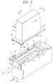
- an upper opening 100 of the container 1 (i.e., an opening 100 through which the developer discharged from a developer replenishing cartridge 3 can drop into the container 1) is closed and opened by a lid 2 supported by guide grooves 1b formed in flange portions of the container 1 for sliding movement in a direction shown by the arrow O and an opposite direction shown by the arrow C.
- a recessed portion 14 for receiving a protruded portion 3b of the cartridge 3, and a guide 1a for guiding the insertion of the protruded portion into the recessed portion.
- an elongated slot 21 extending in the sliding direction is formed on an upper surface of the lid 2.
- a proper amount of replenishing developer D is housed in a container 3a of the developer replenishing cartridge 3, and a developer supply opening 30 of the cartridge is covered or dosed by a slide lid 4 slidably guided by guide grooves 32 formed in flange portions of the container 3a for movement in the direction O and the opposite direction C.
- a projection 41 is formed on the slide lid 4 at an end of the lid in a push-in (slide closing) direction C, which projection is adapted to be hooked by an end portion 22 (in the push-in or slide closing direction C) of the lid 2.
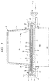
- a thin cavity 42 having openings on both ends thereof (in the sliding direction) is formed in the slide lid 4. That is to say, the slide lid 4 integrally includes a first plate member 43 and a second opposed plate member 44 via the cavity 42.
- a film (flexible seal sheet) 5 made of synthetic resin and the like is peelably adhered, for example, by heat welding, to a peripheral edge surface 31 defining a lower opening of the container 3a in such a manner that the seal sheet can prevent the leak of the developer D.
- a total length of the sheet is selected to have a value greater, by twice or more, than a length of the supply opening 30 along a sheet peeling direction.
- the remaining portion 52 of the sheet 5 which is not adhered to the peripheral edge surface 31 is folded back and is passed through the inner cavity 42 of the slide lid 4 and is firmly secured to a gripper 6 (which is grasped by the operator when he wants to peel the seal sheet from the opening) at a position 61 where the seal sheet 5 does not protrude from the cartridge 3.
- the first sheet portion 51 adhered to the peripheral edge surface 31, 31' seals the supply opening 30 to prevent the leak of the developer in the container 3a.
- the second sheet portion 52 folded back toward the direction O is connected to the gripper 6 so that, when the second sheet portion 52 is pulled toward the direction C by pulling the gripper 6 (by the operator), the first sheet portion 51 is peeled from the peripheral edge surface 31 of the container 3a, thus opening the supply opening 30.
- the rear end portion 31' (in the peeling direction) of the sheet is not separated from the contain an 3a.
- the sheet pulling gripper 6 can be pulled out by the shifting movement of the lid 2 and is fixed to the flange portions of the container 3a, for example, by pinching, clipping or meshing means before the cartridge 3 is mounted on the container 1. Further, the gripper 6 has a projection 62 which is adapted to engage by a rear end 23 (in a pull-out or slide opening direction O) of the elongated slot 21 of the lid 2 to disengage or pull out the gripper from the container 3a.
- the length of the second sheet portion 52 is selected so that the shock caused when the gripper 6 is disengaged from the container 3a by the shifting movement of the lid 2 is not transmitted to the first sheet portion 51. That is to say, the second sheet portion 52 has the surplus length, and, when the gripper 6 is attached to the container 3a, the surplus length of the second sheet portion 52 is housed within the cavity in the slide lid 4 in the folded condition not to protrude from the cartridge 3.
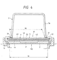
- the dimensional relation between the supply opening 30 of the developer replenishing cartridge 3 and the opening 100 of the developer receiving container 1 is so selected that a dimension K 1 is greater than a dimension K 2 and a dimension W 1 is greater than a dimension W 2 , that is, the opening 100 of the developer receiving container 1 is sufficiently greater than the supply opening 30 of the cartridge 3, because the guide grooves for the lid 4 of the container 3a and the lid 2 of the developer receiving container 1 are prevented from being smeared by the scattered developer when the developer is supplied from the cartridge to the developer receiving container.
- the peripheral edge surface 31 of the container 3a to which the seal sheet 5 is adhered has a step with respect to a sliding plane 32 for the slide lid 4 not to squeeze or compress the seal sheet 5 for permitting the smooth movement of the sheet.
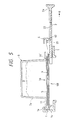
- the lid 2 Immediately before the lid 2 opens the opening 100 of the developer receiving container 1 completely, the rear end wall 23 of the elongated slot 21 formed in the lid 2 is engaged by the projection 62 of the sheet pulling gripper 6, thus starting the disengagement of the gripper 6 from the container 3a through the shifting movement of the lid 2 in the direction O.
- the gripper 6 is disengaged from the container 3a, with the result that the operator can easily pull the gripper.
- the slide lid 4 is urged by the sheet 5 to be shifted in the direction O together with the second sheet portion 52.
- the supply opening 30 of the container 3a begins to be opened, and the developer D starts to be dropped from the cartridge container 3a into the developer receiving container 1, as shown by the arrow F.
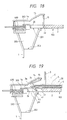
- Fig. 7 shows a condition that the supply opening 30 of the cartridge container 3a is completely opened.
- the slide lid 4 is opposed to the lid 2 again.
- the seal sheet 5 is still secured to the container 3a at the position 31', and the sheet 5 is not completely separated from the container 3a.
- the seal sheet 5 remains to be secured to the container 3a at 31', and, since the sheet is engaged by the slide lid 4 at the folded position as mentioned above, when the slide lid 4 is shifted in the direction C, the sheet 5 is subjected to the shifting force from the slide lid 4 and starts to shift in a direction C opposite to the above-mentioned direction to start to dose the opening 30 again.
- the sheet portion pulled out of the cavity 42 of the slide lid 4 starts to be re-entered into the cavity 42. In this way, the opening 30 of the container 3a is closed.
- the operator is permitted to access the sheet pulling gripper 6 only when the opening 100 of the developer receiving container 1 and the gripper 6 is disengaged from the cartridge 3. Accordingly, it is possible to prevent the accident regarding the scattering of the developer caused when the cartridge is unsealed while closing the lid 2.
- the slide lid 4 of the cartridge 3 is closed in synchronous with the dosing movement of the lid 2 of the developer receiving apparatus. Accordingly, it is possible to prevent the accident regarding the scattering of the residual developer from the cartridge 3 as caused when the cartridge 3 is dismounted from the developer receiving apparatus while not dosing the cartridge with the lid 4.
- seal sheet 5 of the cartridge 3 is protected by the slide lid 4, it is possible to prevent the accident regarding the scattering of the developer as caused when the sheet is teared or damaged.
- the upper surface (surface exposed out of the apparatus) of the lid 2 of the developer receiving container 1 is shielded from the sheet surface to which the developer is adhered, by the plate member 44 of the lid 4, whereby the upper surface of the lid 2 is not smeared by the developer adhered to the sheet surface.
- the plate member 43 of the lid 4 since the sheet portion to which the developer is adhered is covered by the plate member 43 of the lid 4 not to be exposed externally, even if the operator in-advertentiy accesses to such sheet portion, the operator is not smeared with the developer.
- the seal sheet 5 is not separated from the cartridge 3 completely and can be removed from the developer receiving apparatus together with the container 3a and the lid 4 after the cartridge container 3a is dosed by the lid 4 and the sheet, the handling of the disused sheet can be facilitated.
- the developer replenishing cartridge 3 is mounted on the developer receiving container 1 in place, as shown in Fig. 3. That is to say, the cartridge container 3a is rested on the container 1 while inserting a protruded portion 3b of the container 3a into the recessed portion 14 of the container 1.
- the protruded portion 3b of the container 3a is regulated by the guide 1a so as not to shift upwardly. In this condition, the cartridge 3 can be pivoted around the protruded portion 3b.
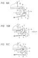
- Locking mechanisms 7 are provided on the developer receiving container 1 at position 101.
- Each locking mechanism includes integral locking pawls 71, 73 which are pivotally mounted on a shaft 74 attached to the container 1.
- a leaf spring 9 urges a portion 72 of the pawl 71 upwardly so that the pawls 71, 73 are elastically biased toward an anti-clockwise direction.
- the locking pawl 71 is disengaged from the hole 24 of the lid 2 to permit the sliding movement of the lid 2.
- the locking pawl 73 is rotated in the anti-clockwise direction under the biasing force of the leaf spring 9 to engage by an upper surface of the projection 33 (refer to Fig. 10B).
- the cartridge 3 is locked at a predetermined position on the container 1, i.e., at a position where the developer is replenished from the cartridge into the container 1.
- the cartridge is prevented from being dismounted from the predetermined position. Since the anti-clockwise rotation of the locking pawl 71 is inhibited by the engagement of the locking pawl 73 with the projection 33, the unlocked condition of the lid 2 is maintained.
- the cartridge 3 is automatically pivoted around the protruded portion 3b and lifted by a biasing force of a spring 8 described below up to a position where, even when the locking pawl 73 is rotated in the anti-clockwise direction again, it cannot engage by the upper surface of the projection 33.
- the operator can understand the fact that the cartridge 3 is unlocked, by ascertaining the automatic elevation of the cartridge 3. Accordingly, since the fact that the cartridge is dismountable can easily be judged, it is possible to prevent the operators miss-operation as to the forcible dismounting of the cartridge 3 from the container 1.
- the lid 2 is subjected to the biasing forces of the leaf springs 9 via the locking pawls 71 and the cam surface 25. Accordingly, when the locking pawls 71, 73 are rotated in the anti-clockwise direction under the biasing forces of the leaf springs 9, the lid 2 is automatically shifted in the direction O by the biasing forces of the springs. At a point where the lid 2 is slightly shifted to the direction O, the locking pawls 71 are re-entered into the corresponding holes 24 of the lid 2 under the biasing forces of the springs 9, thus restoring the condition shown in Fig. 10A. In the condition shown in Fig. 10A, the lid 2 is locked at the position shown in Fig. 3.
- the cartridge 3 can be unlocked only when the lid 2 is further pushed beyond the locked position shown in Fig. 3 where the opening 100 of the container 1 is completely dosed, and the lid 2 is automatically returned to the locked position after the unlocking of the cartridge, it is possible to prevent the cartridge from being dismounted from the developer receiving container in the condition that the opening of the developer receiving container is not completely closed.
- two recesses 102 are formed in the container 1 between the front and rear ends of the opening 100 (in the sliding direction of the lid 2) and at both lateral sides of the opening 100.
- Leaf springs 8 are disposed in these recesses 102.
- two projections 34 (only one of the which is shown) adapted to be inserted into the recesses 102 are formed on the flange portions of the cartridge container 3a.
- the biasing force of the leaf springs 8 contributes to ensure the engagement between the locking pawls 73 and the projections 33 and serves to lift the cartridge 3 as mentioned above when the locking pawls 73 are disengaged from the projections 33.
- the projections 34 and the recesses 102 aid to the locking operation by means of the locking pawls 73.
- the projections 34 and the recesses 102 can prevent the inadvertent unlocking due to the excessive load applied to the locking mechanisms 7 during the opening/closing of the opening 30.
- the recesses 102 has the function to identify the cartridge. That is to say, only the cartridge having the projections 34 in correspondence to the recesses 102 can be mounted on the developer receiving container at the predetermined position. Accordingly, by differentiating the position of the projections 34 on the cartridge in correspondence to the kinds of developer, any cartridge containing the developer unnecessary to the specific image forming system cannot be mounted, at the predetermined position, on the developer receiving container for such image forming system, and, thus, it is possible to prevent the replenishment of the unnecessary or unsuited developer into the developer receiving container.
- the leaf springs may be abutted against the cartridge 3 at any portions other than the projections 34.
- the projections may be formed on the container 1 and the recesses corresponding to such projections may be formed in the cartridge to achieve the same function as that obtained by the above-mentioned projections 34 and the recesses 120.
- Figs. 12A to 12D show another embodiment.
- a spring 10 is abutted against a rear end 26 (in a direction O) of the lid 2 to elastically bias the lid 2 toward the direction O.
- Figs. 12A, 12B and 12D correspond to Figs. 10A, 10B and 10C, respectively.
- the operator In order to unlock the cartridge 3, the operator must shift the lid 2 in the direction C in opposition to the biasing force of the spring 10. However, when the lid 2 is automatically returned from the unlocked position for the cartridge 3 to the locked position for the lid 2 itself, the biasing force of the spring 10 aids such returning of the lid 2, as well as the biasing force of the springs 9.
- Figs. 13A to 13C show another embodiment of a locking mechanism.
- the lid 2 of the developer receiving container 1 is engaged by a locking pawl 602 of a locking mechanism 600 via a hole 24 formed in the lid itself, thus preventing the shifting movement of the lid.
- the locking pawl 602 is pivotally mounted on a pivot pin 601 formed on the developer receiving container 1 and is always biased toward the hole 24 of the lid 2 by an elastic member (leaf spring) 8. Further, the locking pawl 602 itself may be constituted by an elastic member to omit the elastic member 8.
- another locking mechanism 700 is arranged in the recess 101 of the lid 2.
- the locking mechanism 700 is similar to the above-mentioned locking mechanism 7, but, in place of the locking pawl 71, a cam engagement projection 76 is integrally formed on the locking pawl 73, and, in place of the leaf spring 9, a coil spring 900 is hooked to the locking pawl 73 to bias the locking pawl 73 and projection 76 in the anti-clockwise direction.
- the projection 33 of the developer receiving container 1 rotates the locking pawl 73 in the clockwise direction.
- the projection 33 is engaged by the locking pawl 73. This prevents the dismounting of the cartridge in cooperation with the protruded portion 3b of the cartridge 3 inserted into the recessed portion 14.
- the developer is supplied from the cartridge into the container 1 as mentioned above.
- the lid 2 is pushed to the position of Fig. 3. From this condition, as shown in Fig. 13C, when the lid 2 is further pushed toward the direction C, the cam surface 25 of the lid 2 urges the projection 76 integral with the locking pawl 73, thus rotating the locking pawl 73 in the clockwise direction in opposition to the coil spring 900. As a result, the locking pawl 73 is disengaged from the projection 33 of the cartridge 3. Consequently, the cartridge 3 is automatically lifted by the biasing force of the elastic member 8. In this condition, the cartridge 3 can be dismounted from the container 1 while retracting the protruded portion 3b from the recessed portion 14.
- the lid 2 is returned to the position of Fig. 13A.
- the lid 2 may be manually pulled until the locking pawl 602 is re-entered into the hole 24 of the lid 2.
- the lid 2 must be dosed while pushing a mountain of developer aside by the end projection 41 of the slide lid 4 to push the excessive developer back to the developer replenishing cartridge 3.
- the developer comprised of small particles has the good fluidity, but is likely to be lumped.
- the developer is pressed together by the ends of the lids and is jammed at a portion T in Fig. 8, thus opposing to the dosing movement of the lids 2, 4.
- the developer replenishing cartridge 3 cannot be dismounted from the developer receiving container 1.
- the developer receiving container 1 is provided with a buffer chamber for receiving the excessive developer to eliminate the resistance to the dosing movement of the lids 2, 4, thus ensuring that the slide lid 4 of the developer replenishing cartridge can be dosed without fail.
- the developer receiving container 1 has a buffer chamber 200 disposed beside the opening 100 of the container 1 and adjacent to the front end (in the push-in direction C) of the lid 2 when the opening 100 is completely dosed by the lid 2.
- the buffer chamber 200 has an excessive developer introducing opening 201 disposed in substantially the same plane as the opening 100 of the developer receiving container 1.
- the opening 201 is closed by a lid 300 biased toward a closing direction (opening direction O for the lids 2, 4) by means of an elastic member 400, in a condition that the developer replenishing cartridge 3 is not mounted on the developer receiving container 1.
- the lid 300 is pushed and opened by the end portion 26 (in the dosing direction) of the lid 2 in opposition to a biasing force of the elastic member (spring) 400.
- the lid 300 may remain to be closed.
- the protruded portion 3b of the developer replenshing cartridge 3 When the protruded portion 3b of the developer replenshing cartridge 3 is inserted between the guide 1a of the developer receiving container 1 and the lid 300, the protruded portion 3b contacts the lid 300 with a strength not to disturb the sliding the lid 300, while the upward movement of the protruded portion being limited by the guide 1a.
- the lid 300 is urged in the closing direction by the elastic member 400 to close the opening 201 of the buffer chamber 200 with contacting with the lower surface of the protruded portion 3b of the developer replenishing container 3a.
- the developer overflowed from the developer receiving container 1 does not enter into the buffer chamber 200 and remains in the developer replenishing container 3a.
- the end face 22 of the lid 2 engages with the projection 41 of the lid 4 to push the lid 4, with the result that the lids 2, 4 are advanced while pushing the developer aside by the projection 41.
- a left extension may be formed on the lid 4 to open the lid 300 by urging the latter by the extension.
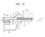
- FIG. 18 A further embodiment is shown in Figs. 18 to 21.
- a further opening 202 is formed in a bottom of the buffer chamber 200 to communicate with the interior of the developer receiving container 1.
- the buffer chamber 200 has the bottom opening 202. Further, in order to prevent the natural scattering of the developer from the buffer chamber 200 through the entrance (for the protruded portion 3b of the cartridge) of the recessed portion 14 of the container 1, an auxiliary lid 15 is pivotally mounted at the entrance. In a condition that the cartridge 3 is not mounted on the developer receiving container 1, the lid 15 is abutted against the end face 22 of the lid 2 by its own weight or by a coil spring and the like to close the entrance.
- the developer replenishing cartridge 3 is mounted on the developer receiving apparatus while opening the lid 15 by the protruded portion 3b, as shown in Fig. 19.
- the lid 300 can be forcibly opened by the lid 2. However, when the developer is being replenished, the lid 300 doses the opening 201 of the buffer chamber 200 via the biasing force of the spring or elastic member 400, as shown in Fig. 20. The replenishment of the developer into the developer receiving container 1 is effected in the same manner as the previous embodiment.
- the bottom opening 202 has a dimension so that the buffer chamber 200 is filled with the developer from the container 1 through the opening 202 during the replenishment of the developer.
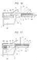
- the end face 22 of the lid 2 has a convex wedged shape
- the projection 41 of the lid 4 includes an inner surface (to be engaged by the end face 22) having a complementary concave wedged shape.
- the movement of the seal sheet 5 aids to reduce the resistance between the developer and the lid 4 when the lids 2, 4 are being dosed while pushing the developer aside.
- the lid 300 is forcibly opened by the end portion 26 of the lid 2, with the result that the excessive developer is pushed into the buffer chamber 200. Consequently, the opening 30 can be completely closed by the lid 4, as shown in Fig. 21.
- the projection 43 of the lid 4 is fitted into a recess 3d formed in the flange portion of the cartridge container. Accordingly, after the cartridge 3 is dismounted from the developer receiving container 1, for example, even when the operator grips the protruded portion of the container 3a to suspend the container 3a laterally, since the projection 43 of the lid 4 is caught by a projection 3c defining the recess 3d of the container 3a, it is possible to prevent the lid 4 from sliding down or dropping out of the container 3a by its own weight.
- the lid 4 when the lid 4 is being opened or closed by the operator's manipulation, since the projection 43 can be elastically deformed downwardly by the abutment against the projection 3c to easily override the latter due to the elasticity of the lid 4 made of synthetic resin, the opening and dosing movement of the lid is not obstructed.
- a recess for receiving the projection 3c of the container 3a may be formed in the lid 4.
- the developer entered into the buffer chamber 200 is sent to the container 1 to be used.
- the function or ability of the buffer chamber does not depend upon the volume of the buffer chamber, and, therefore, the buffer chamber can be used repeatedly.
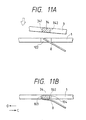
- the seal sheet 5 has a width W3 wider than a width of the supply opening 30 at a sheet section where it is adhered to the edge surface defining the opening 30 of the developer replenishing container 3a, and a width W4 narrower than the width W4 at a sheet section where it is drawn from the slide lid 4.
- the width W4 of the seal sheet is sufficiently narrow to permit the sheet to pass between two first grip portions 28 spaced apart in a direction perpendicular to the sliding direction of the lid 2, so that, when the lid 2 is being dosed, the sheet 5 can be retracted into the lid 4 through between the first grip portions 28 of the lid 2.
- the operator may merely push the first grip portions 28 of the grip 2a in a direction shown by the arrows by his hand.
- a second grip portion 27 is formed on the grip 2a between the first grip portions 28.
- the grip portion 27 has an inclined surface against which the depended seal sheet 5 is slidably contacted.
- the inclined surface is positioned below the first grip portions (pushing grip portions) 28 (see Fig. 23). Since the seal sheet 5 stripped during the developer replenishing operation is retracted into the developer replenishing cartridge via the inclined surface lower than the first pushing grip portions 28 of the lid 2 as the lid 2 is forcibly closed, the operability of the lid dosing movement is improved. Incidentally, the operator may pull out the lid 2 by pulling the second grip portion 27.
Landscapes
- Physics & Mathematics (AREA)
- General Physics & Mathematics (AREA)
- Dry Development In Electrophotography (AREA)
Claims (17)
- Système de réapprovisionnement en développateur comportant une cartouche de réapprovisionnement en développateur et un appareil de réception de développateur pour ramener un développateur depuis la cartouche (3) de réapprovisionnement en développateur à l'appareil (1) de réception de développateur d'un appareil électro-photographique de formation d'images, dans lequel l'appareil de réception de développateur comporte :une partie d'accouplement ayant une ouverture rectangulaire pour recevoir le développateur ;des premier et second éléments de verrouillage (7) positionnés sur des côtés opposés de ladite ouverture rectangulaire à proximité immédiate d'une extrémité de celle-ci pour effectuer un mouvement de pivotement entre une position de verrouillage et une position de libération ;un couvercle (2) monté de façon à effectuer un mouvement coulissant dans la direction longitudinale de ladite ouverture entre une position fermée dans laquelle le couvercle ferme l'ouverture et une position ouverte, le couvercle (2) étant formé de façon à comporter des formations de verrouillage (24) pouvant coopérer avec lesdits premier et second éléments de verrouillage (7) lorsque les éléments de verrouillage (7) sont dans leur position de verrouillage et que le couvercle est dans sa position fermée, afin d'empêcher tout mouvement relatif du couvercle et de la partie d'accouplement ; etchaque élément de verrouillage (7) est en outre pourvu d'une surface de contre-came (75) destinée à recevoir une force pour déplacer l'élément de verrouillage (7) de sa position de verrouillage à sa position de libération ;et la cartouche (3) de réapprovisionnement en développateur comporte :un récipient (3a) à développateur ayant une ouverture (30) de décharge de développateur ;un moyen de fermeture (4, 5) fermant ladite ouverture de décharge (30) et conçu pour être ouvert pour permettre au développateur d'être déchargé dudit récipient (3a) à travers ladite ouverture de décharge (30) ;une partie d'accouplement destinée à être reliée à la partie d'accouplement de l'appareil (1) de réception de développateur, la partie d'accouplement de la cartouche (3) de réapprovisionnement en développateur comportant :une face extrême (3b) de forme rectangulaire entourant ladite ouverture de décharge et conçue pour être reliée à la partie d'accouplement de l'appareil (1) de réception de développateur ; etdes première et seconde saillies (33) situées sur des côtés opposés de ladite face extrême rectangulaire ;l'agencement est tel que, lorsque ladite partie d'accouplement de ladite cartouche (3) de réapprovisionnement en développateur est engagée avec ladite partie d'accouplement dudit appareil (1) de réception de développateur, les première et seconde saillies (33) engagent des surfaces de contre-came respectives (75) de certains, respectifs, desdits premiers et seconds éléments de verrouillage (7) et fassent tourner lesdits éléments de verrouillage de leurs positions de verrouillage à leurs positions de libération.
- Cartouche (3) de réapprovisionnement en développateur destinée à être utilisée avec un appareil (1) de réception de développateur d'un appareil électro-photographique de formation d'images, l'appareil de réception de développateur comportant une partie d'accouplement ayant une ouverture rectangulaire allongée pour recevoir le développateur, des premier et second éléments de verrouillage (7) positionnés sur des côtés opposés de ladite ouverture rectangulaire à proximité immédiate de l'une de ses extrémités afin d'effectuer un mouvement de pivotement entre une position de verrouillage et une position de libération, un couvercle (2) monté de façon à effectuer un mouvement coulissant dans la direction longitudinale de ladite ouverture entre une position fermée dans laquelle le couvercle ferme l'ouverture et une position ouverte, le couvercle (2) étant formé de façon à comporter des formations de verrouillage (24) pouvant coopérer avec lesdits premier et second éléments de verrouillage (7) lorsque les éléments de verrouillage (7) sont dans leur position de verrouillage et que le couvercle est dans sa position fermée afin d'empêcher tout mouvement relatif du couvercle et de la partie d'accouplement, et dans lequel chaque élément de verrouillage (7) est en outre pourvu d'une surface de contre-came (75) destinée à recevoir une force pour déplacer l'élément de verrouillage (7) de sa position de verrouillage à sa position de libération, la cartouche (3) de réapprovisionnement en développateur comportant :un récipient (3a) à développateur ayant une ouverture (30) de décharge de développateur ;un moyen de fermeture (4, 5) fermant ladite ouverture de décharge (30) et conçu pour être ouvert pour permettre au développateur d'être déchargé dudit récipient (3a) à travers ladite ouverture de décharge (30) ;une partie d'accouplement destinée à être reliée à la partie d'accouplement de l'appareil (1) de réception de développateur, la partie d'accouplement de la cartouche (3) de réapprovisionnement en développateur comportant :une face extrême (3b) de forme rectangulaire entourant ladite ouverture de décharge et conçue pour être reliée à la partie d'accouplement de l'appareil (1) de réception de développateur ; etdes première et seconde saillies (33) situées sur des côtés opposés de ladite face extrême rectangulaire et conçues pour engager des surfaces de contre-came respectives (75) de certains, respectifs, desdits premiers et seconds éléments de verrouillage (7) de ladite partie d'accouplement dudit appareil (1) de réception de développateur afin de faire tourner lesdits éléments de verrouillage de leurs positions de verrouillage à leurs positions de libération.
- Cartouche (3) de réapprovisionnement en développateur selon la revendication 2, dans laquelle le moyen de fermeture comporte une feuille souple (5) comprenant une première partie pelable (51) qui obture l'ouverture (30) et une seconde partie allongée (52) qui peut être tirée afin que la feuille soit enlevée par pelage de l'ouverture dans une direction de pelage.
- Cartouche (3) de réapprovisionnement en développateur selon la revendication 3, dans laquelle le moyen de fermeture comprend en outre un couvercle (4) de récipient supporté de façon coulissante pour se déplacer dans ladite direction de pelage entre une première position dans laquelle le couvercle (4) du récipient recouvre l'ouverture (30) et une seconde position dans laquelle l'ouverture est à découvert, dans laquelle la feuille souple (5) peut être pliée jusqu'en engagement avec le couvercle du récipient pour déplacer le couvercle de sa première à sa seconde position pendant que la première partie (51) de la feuille souple est détachée par pelage de l'ouverture (30), et dans laquelle une extrémité de ladite première partie (51) de ladite feuille souple (5) est fixée audit récipient (3a) à développateur afin qu'un retour du couvercle (4) du récipient vers sa première position replace ladite première partie de ladite feuille souple sur l'ouverture (30).
- Cartouche (3) de réapprovisionnement en développateur selon la revendication 4, dans laquelle le couvercle (4) du récipient est formé de façon à présenter une cavité (42) s'étendant depuis une extrémité dudit couvercle jusqu'à l'autre extrémité dans ladite direction de pelage pour recevoir ladite première partie (51) de ladite feuille souple pendant que le couvercle du récipient est déplacé vers sa seconde position.
- Cartouche (3) de réapprovisionnement en développateur selon la revendication 5, dans laquelle le couvercle (4) du récipient comporte une première partie de couvercle et une seconde partie de couvercle, et dans laquelle, lorsque le couvercle du récipient est dans sa position fermée, ladite première partie de couvercle est positionnée entre ladite première partie (51) et ladite seconde partie (52) de ladite feuille souple (5) et ladite seconde partie de couvercle est positionnée sur le côté de ladite seconde partie (52) de ladite feuille souple éloigné de ladite première partie (51).
- Cartouche (3) de réapprovisionnement en développateur selon l'une quelconque des revendications 3 à 6, dans laquelle la longueur de ladite seconde partie (52) de ladite feuille souple (5) est égale ou supérieure à la longueur de la première partie (51) de ladite feuille souple (5), dans la direction de pelage.
- Cartouche (3) de réapprovisionnement en développateur selon l'une quelconque des revendications 3 à 7, dans laquelle la première partie (51) de la feuille souple (5) a une largeur (W3) supérieure à la largeur de l'ouverture (30) de décharge de développateur.
- Cartouche (3) de réapprovisionnement en développateur selon l'une quelconque des revendications 3 à 8, dans laquelle une prise (6) est fixée à une extrémité de la seconde partie (52) de la feuille souple (5) éloignée de ladite première partie (51).
- Cartouche (3) de réapprovisionnement en développateur selon la revendication 9, dans laquelle la prise (6) est reliée de façon amovible au récipient à développateur.
- Cartouche (3) de réapprovisionnement en développateur selon la revendication 10, dans laquelle au moins la portion de la seconde partie (52) de la feuille souple (5) adjacente à la prise (6) a une largeur (W4) non supérieure à la largeur de l'ouverture (30) de décharge de développateur.
- Cartouche (3) de réapprovisionnement en développateur selon la revendication 10 ou la revendication 11, dans laquelle une longueur libre de ladite seconde partie (52) de ladite feuille souple (5) est stockée dans une portion du récipient (3) jusqu'à ce que la prise (6) soit détachée du récipient.
- Cartouche (3) de réapprovisionnement en développateur selon la revendication 12, dans laquelle ladite longueur libre de la seconde partie (52) de ladite feuille souple (5) est stockée à l'intérieur de la cavité (42) dans le couvercle (4) du récipient.
- Cartouche (3) de réapprovisionnement en développateur selon l'une quelconque des revendications 3 à 13, dans laquelle le couvercle (4) du récipient est pourvu d'une partie d'engagement (41) pouvant coopérer avec une partie d'engagement (22) dudit couvercle (2) de l'appareil de réception de développateur pour transmettre une force de fermeture dudit couvercle (2) audit couvercle (4) du récipient lorsque ledit couvercle (2) de l'appareil de réception de développateur est déplacé vers sa position fermée, et dans laquelle ladite force de fermeture appliquée audit couvercle du récipient peut agir de façon à replacer ladite feuille souple (5) sur ladite ouverture (30) d'amenée.
- Appareil de réception de développateur destiné à être utilisé avec une cartouche (3) de réapprovisionnement en développateur comportant un récipient (3a) à développateur ayant une ouverture (30) de décharge de développateur, un moyen de fermeture (4, 5) fermant ladite ouverture (30) de décharge et conçu pour être ouvert afin de permettre au développateur d'être déchargé dudit récipient (3a) à travers ladite ouverture de décharge (30), une partie d'accouplement destinée à être reliée à une partie d'accouplement de l'appareil (1) de réception de développateur, la partie d'accouplement de la cartouche (3) de réapprovisionnement en développateur comportant une face extrême (3b) de forme rectangulaire entourant ladite ouverture de décharge et conçue pour être reliée à la partie d'accouplement de l'appareil (1) de réception de développateur et des première et seconde saillies (33) situées sur des côtés opposés de ladite face extrême rectangulaire ;
l'appareil de réception de développateur comportant :une partie d'accouplement ayant une ouverture rectangulaire (100) destinée à recevoir le développateur ;des premier et second éléments de verrouillage (7) positionnés sur des côtés opposés de ladite ouverture rectangulaire à proximité immédiate d'une extrémité de celle-ci pour effectuer un mouvement de pivotement entre une position de verrouillage et une position de libération ;un couvercle (2) monté de façon à effectuer un mouvement coulissant dans la direction longitudinale de ladite ouverture entre une position fermée dans laquelle le couvercle ferme l'ouverture et une position ouverte, le couvercle (2) étant formé de façon à comporter des formations (24) de verrouillage pouvant coopérer avec lesdits premier et second éléments de verrouillage (7) lorsque les éléments de verrouillage (7) sont dans leur position de verrouillage et que le couvercle est dans sa position fermée, afin d'empêcher tout mouvement relatif du couvercle et de la partie d'accouplement ; etchaque élément de verrouillage (7) étant pourvu en outre d'une surface de contre-came (75) destinée à recevoir une force pour déplacer l'élément de verrouillage (7) de sa position de verrouillage à sa position de libération ;et l'agencement étant tel que, lorsque ladite partie d'accouplement de ladite cartouche (3) de réapprovisionnement en développateur est engagée avec ladite partie d'accouplement dudit appareil (1) de réception de développateur, les première et seconde saillies (33) engagent des surfaces de contre-came respectives (75) de certains, respectifs, desdits premiers et seconds éléments de verrouillage (7) et fassent tournent lesdits éléments de verrouillage de leurs positions de verrouillage à leurs positions de libération. - Appareil de réception de développateur selon la revendication 15, dans lequel lesdits éléments de verrouillage (7) peuvent pivoter autour d'un axe s'étendant parallèlement au plan de l'ouverture et transversalement à la direction d'allongement de l'ouverture rectangulaire (100).
- Appareil de réception de développateur selon la revendication 15 ou la revendication 16, dans lequel ledit couvercle (2) de l'appareil de réception de développateur comporte un moyen d'engagement (22) pouvant coopérer avec une partie d'engagement (41) dudit couvercle (4) du récipient pour transmettre une force de fermeture dudit couvercle (2) audit couvercle (4) du récipient lorsque ledit couvercle (2) de l'appareil de réception de développateur est déplacé vers sa position fermée.
Priority Applications (2)
| Application Number | Priority Date | Filing Date | Title |
|---|---|---|---|
| EP02076134A EP1223477B1 (fr) | 1991-05-14 | 1992-05-14 | Récipient de fourniture de développateur |
| EP02076127A EP1223476B1 (fr) | 1991-05-14 | 1992-05-14 | Récipient de fourniture de développateur et appareil de réception de développateur dans lequel ce récipient est monté |
Applications Claiming Priority (16)
| Application Number | Priority Date | Filing Date | Title |
|---|---|---|---|
| JP10923391 | 1991-05-14 | ||
| JP3109233A JP2953678B2 (ja) | 1991-05-14 | 1991-05-14 | 現像剤容器 |
| JP109233/91 | 1991-05-14 | ||
| JP120055/91 | 1991-05-24 | ||
| JP3120055A JP2862399B2 (ja) | 1991-05-24 | 1991-05-24 | 現像剤補充容器、及び、現像剤補充方法 |
| JP12005691 | 1991-05-24 | ||
| JP120056/91 | 1991-05-24 | ||
| JP12005591 | 1991-05-24 | ||
| JP3120056A JP2810559B2 (ja) | 1991-05-24 | 1991-05-24 | 現像剤補充容器、及び、現像剤補充方法 |
| JP3120064A JP2738885B2 (ja) | 1991-05-24 | 1991-05-24 | 現像剤補充容器、及び、現像剤補充方法 |
| JP120064/91 | 1991-05-24 | ||
| JP12006491 | 1991-05-24 | ||
| JP03167038A JP3143495B2 (ja) | 1991-07-08 | 1991-07-08 | 現像剤補給装置と現像剤補充容器 |
| JP167038/91 | 1991-07-08 | ||
| JP16703891 | 1991-07-08 | ||
| EP92304345A EP0514168B1 (fr) | 1991-05-14 | 1992-05-14 | Cartouche de fourniture de développeur et appareil de réception de développeur dans lequel cette cartouche est montée |
Related Parent Applications (2)
| Application Number | Title | Priority Date | Filing Date |
|---|---|---|---|
| EP92304345A Division EP0514168B1 (fr) | 1991-05-14 | 1992-05-14 | Cartouche de fourniture de développeur et appareil de réception de développeur dans lequel cette cartouche est montée |
| EP92304345.9 Division | 1992-05-14 |
Related Child Applications (2)
| Application Number | Title | Priority Date | Filing Date |
|---|---|---|---|
| EP02076134A Division EP1223477B1 (fr) | 1991-05-14 | 1992-05-14 | Récipient de fourniture de développateur |
| EP02076127A Division EP1223476B1 (fr) | 1991-05-14 | 1992-05-14 | Récipient de fourniture de développateur et appareil de réception de développateur dans lequel ce récipient est monté |
Publications (3)
| Publication Number | Publication Date |
|---|---|
| EP0840177A2 EP0840177A2 (fr) | 1998-05-06 |
| EP0840177A3 EP0840177A3 (fr) | 1999-04-07 |
| EP0840177B1 true EP0840177B1 (fr) | 2002-07-31 |
Family
ID=27526394
Family Applications (6)
| Application Number | Title | Priority Date | Filing Date |
|---|---|---|---|
| EP97204123A Expired - Lifetime EP0840177B1 (fr) | 1991-05-14 | 1992-05-14 | Cartouche de fourniture de développeur et appareil de réception de développeur dans lequel cette cartouche est montée |
| EP02076127A Expired - Lifetime EP1223476B1 (fr) | 1991-05-14 | 1992-05-14 | Récipient de fourniture de développateur et appareil de réception de développateur dans lequel ce récipient est monté |
| EP92304345A Expired - Lifetime EP0514168B1 (fr) | 1991-05-14 | 1992-05-14 | Cartouche de fourniture de développeur et appareil de réception de développeur dans lequel cette cartouche est montée |
| EP02076134A Expired - Lifetime EP1223477B1 (fr) | 1991-05-14 | 1992-05-14 | Récipient de fourniture de développateur |
| EP95201571A Expired - Lifetime EP0675416B1 (fr) | 1991-05-14 | 1992-05-14 | Cartouche de fourniture de développateur et appareil de réception de développateur dans lequel cette cartouche est montée |
| EP97204122A Expired - Lifetime EP0841597B1 (fr) | 1991-05-14 | 1992-05-14 | Cartouche de fourniture de développateur et appareil de réception de développateur dans lequel cette cartouche est montée |
Family Applications After (5)
| Application Number | Title | Priority Date | Filing Date |
|---|---|---|---|
| EP02076127A Expired - Lifetime EP1223476B1 (fr) | 1991-05-14 | 1992-05-14 | Récipient de fourniture de développateur et appareil de réception de développateur dans lequel ce récipient est monté |
| EP92304345A Expired - Lifetime EP0514168B1 (fr) | 1991-05-14 | 1992-05-14 | Cartouche de fourniture de développeur et appareil de réception de développeur dans lequel cette cartouche est montée |
| EP02076134A Expired - Lifetime EP1223477B1 (fr) | 1991-05-14 | 1992-05-14 | Récipient de fourniture de développateur |
| EP95201571A Expired - Lifetime EP0675416B1 (fr) | 1991-05-14 | 1992-05-14 | Cartouche de fourniture de développateur et appareil de réception de développateur dans lequel cette cartouche est montée |
| EP97204122A Expired - Lifetime EP0841597B1 (fr) | 1991-05-14 | 1992-05-14 | Cartouche de fourniture de développateur et appareil de réception de développateur dans lequel cette cartouche est montée |
Country Status (6)
| Country | Link |
|---|---|
| US (2) | US5513679A (fr) |
| EP (6) | EP0840177B1 (fr) |
| KR (2) | KR0132139B1 (fr) |
| CA (1) | CA2068358C (fr) |
| DE (6) | DE69226982T2 (fr) |
| HK (4) | HK1010584A1 (fr) |
Families Citing this family (40)
| Publication number | Priority date | Publication date | Assignee | Title |
|---|---|---|---|---|
| JP3210175B2 (ja) * | 1993-06-10 | 2001-09-17 | キヤノン株式会社 | 現像剤補給容器及び前記容器の組み立て方法 |
| JPH08234552A (ja) * | 1995-02-23 | 1996-09-13 | Canon Inc | 画像形成装置、プロセスカートリッジ、現像装置及び現像剤補給容器 |
| KR0129183Y1 (ko) * | 1995-03-09 | 1999-03-20 | 김광호 | 화상형성 장치의 토너 누출 방지 장치 |
| JPH08314247A (ja) * | 1995-05-16 | 1996-11-29 | Canon Inc | 現像装置、プロセスカートリッジおよび画像形成装置 |
| JP3507222B2 (ja) * | 1995-10-26 | 2004-03-15 | キヤノン株式会社 | トナー補給容器 |
| JP3471992B2 (ja) * | 1995-10-26 | 2003-12-02 | キヤノン株式会社 | トナー補給容器及び画像形成装置 |
| FR2748331B1 (fr) * | 1996-05-02 | 1998-06-12 | Sagem | Ensemble de deux recipients destines a communiquer entre eux pour le chargement de l'un par l'autre en un produit consommable |
| JP3445069B2 (ja) * | 1996-07-24 | 2003-09-08 | キヤノン株式会社 | 現像ユニット及びプロセスカートリッジ及び画像形成装置 |
| IT1284596B1 (it) * | 1996-09-27 | 1998-05-21 | Luigi Goglio | Contenitore di prodotti granulari in particolare caffe' e relativo supporto per lo svuotamento in una macina da bar |
| JP3495916B2 (ja) * | 1997-08-01 | 2004-02-09 | キヤノン株式会社 | シール部材及びトナー容器 |
| JP3495914B2 (ja) * | 1998-06-24 | 2004-02-09 | キヤノン株式会社 | トナー補給容器及びトナー補給装置ならびにこれらを用いたトナー補給方法 |
| TW517179B (en) * | 1999-03-29 | 2003-01-11 | Canon Kk | Developer replenishing container, cartridge and image forming apparatus |
| US6591077B2 (en) * | 2000-05-08 | 2003-07-08 | Ricoh Company, Ltd. | Image forming apparatus and toner container therefor |
| US6484412B1 (en) * | 2000-07-14 | 2002-11-26 | Penshar, Inc. | Non-spill chalk line and measured refill cartridge |
| EP1176477A1 (fr) * | 2000-07-24 | 2002-01-30 | Océ-Technologies B.V. | Mécanisme de remplissage de poudre de toner |
| JP3535818B2 (ja) * | 2000-08-31 | 2004-06-07 | 株式会社リコー | 容器およびこれの支持構造および画像形成装置 |
| JP3907408B2 (ja) | 2000-12-28 | 2007-04-18 | キヤノン株式会社 | 画像形成装置 |
| ES2382727T3 (es) * | 2001-02-19 | 2012-06-12 | Canon Kabushiki Kaisha | Contenedor para suministro de toner |
| US6990301B2 (en) * | 2001-02-19 | 2006-01-24 | Canon Kabushiki Kaisha | Sealing member, toner accommodating container and image forming apparatus |
| TW525794U (en) | 2001-11-12 | 2003-03-21 | Gen Plastic Ind Co Ltd | Powder supply apparatus of carbon powder cartridge |
| TW524201U (en) * | 2002-02-08 | 2003-03-11 | Gen Plastic Ind Co Ltd | Mechanism for preventing assembling fault |
| US6668145B2 (en) * | 2002-03-08 | 2003-12-23 | General Plastic Industrial Co., Ltd. | Toner cartridge opening control arrangement |
| JP4143325B2 (ja) * | 2002-04-26 | 2008-09-03 | キヤノン株式会社 | トナー補給容器及び駆動伝達部材 |
| TW551513U (en) * | 2002-06-11 | 2003-09-01 | Gen Plastic Ind Co Ltd | Carbon powder cartridge |
| DE10261199B4 (de) * | 2002-12-20 | 2005-06-02 | R. & A. Leibfarth Gmbh | Verschlusseinrichtung für eine Kartusche |
| US7155138B2 (en) * | 2003-12-22 | 2006-12-26 | Canon Kabushiki Kaisha | Developer supply container |
| US7437095B2 (en) * | 2004-06-04 | 2008-10-14 | Oki Data Corporation | Image forming apparatus and toner cartridge |
| JP4456957B2 (ja) * | 2004-08-06 | 2010-04-28 | 株式会社リコー | トナーカートリッジ及び画像形成装置 |
| CN2742471Y (zh) * | 2004-09-07 | 2005-11-23 | 珠海天威飞马打印耗材有限公司 | 显影粉盒 |
| JP4621019B2 (ja) * | 2004-12-17 | 2011-01-26 | キヤノン株式会社 | 現像剤補給容器 |
| TWI332128B (en) * | 2005-04-27 | 2010-10-21 | Ricoh Co Ltd | Toner container and image forming apparatus |
| ES2533553T3 (es) | 2005-06-07 | 2015-04-13 | Ricoh Company, Ltd. | Recipiente de tóner y aparato de formación de imagen |
| DE102006007304B3 (de) * | 2006-02-16 | 2007-09-13 | OCé PRINTING SYSTEMS GMBH | Anordnung zur Förderung von Toner aus einem Tonervorratsbehälter in einen Toneraufnahmebehälter insbesondere bei einer Druck- oder Kopiereinrichtung |
| US8050597B2 (en) * | 2006-11-09 | 2011-11-01 | Ricoh Company, Limited | Toner container having a gear portion and image forming apparatus |
| JP5067113B2 (ja) * | 2007-10-24 | 2012-11-07 | コニカミノルタビジネステクノロジーズ株式会社 | 画像形成装置 |
| US7953347B2 (en) * | 2007-11-14 | 2011-05-31 | Lexmark International, Inc. | Retaining devices and methods for retaining a developer unit of an image forming device |
| JP6566787B2 (ja) | 2015-08-27 | 2019-08-28 | キヤノン株式会社 | 現像剤補給容器 |
| JP6753112B2 (ja) * | 2016-03-31 | 2020-09-09 | ブラザー工業株式会社 | 現像剤カートリッジおよび現像剤収容ユニット |
| CN111770884B (zh) * | 2018-02-05 | 2022-08-30 | 埃科莱布美国股份有限公司 | 用于非接触式化学品分配的包装和对接系统 |
| US11401084B2 (en) | 2019-02-05 | 2022-08-02 | Ecolab Usa Inc. | Packaging and docking system for non-contact chemical dispensing |
Family Cites Families (43)
| Publication number | Priority date | Publication date | Assignee | Title |
|---|---|---|---|---|
| US4142655A (en) * | 1977-05-31 | 1979-03-06 | Xerox Corporation | Toner dispensing and supply arrangement |
| JPS5738673U (fr) | 1980-08-17 | 1982-03-02 | ||
| JPS5738673A (en) * | 1980-08-19 | 1982-03-03 | Matsushita Electric Ind Co Ltd | Open/close device driven by solar heat |
| JPS58224364A (ja) * | 1982-06-23 | 1983-12-26 | Konishiroku Photo Ind Co Ltd | 粉体収納容器 |
| JPS597453U (ja) * | 1982-07-02 | 1984-01-18 | コニカ株式会社 | トナ−容器ユニツト |
| EP0102002B1 (fr) * | 1982-08-23 | 1987-11-04 | Konica Corporation | Dispositif distributeur de toner |
| JPS5957262A (ja) * | 1982-09-25 | 1984-04-02 | Konishiroku Photo Ind Co Ltd | トナ−受入れ装置 |
| JPS59181457U (ja) * | 1983-05-18 | 1984-12-04 | 株式会社リコー | トナ−カ−トリツジ容器 |
| JPH0631055B2 (ja) * | 1984-01-23 | 1994-04-27 | ヤマハ発動機株式会社 | 自動二輪車の燃料装置 |
| JPS60177372A (ja) * | 1984-02-24 | 1985-09-11 | Ricoh Co Ltd | トナ−カ−トリツジ |
| JPS60198567A (ja) * | 1984-03-21 | 1985-10-08 | Minolta Camera Co Ltd | トナ−補充装置 |
| JPS61153054A (ja) * | 1985-04-01 | 1986-07-11 | Honda Motor Co Ltd | 静油圧式無段変速機 |
| JPH0447732Y2 (fr) * | 1986-09-18 | 1992-11-11 | ||
| DE3637836A1 (de) * | 1986-11-06 | 1988-05-19 | Wacker Chemie Gmbh | Waessrige silicondispersionen |
| JPS63170851A (ja) * | 1987-01-08 | 1988-07-14 | Matsushita Electric Ind Co Ltd | アルカリ蓄電池用カドミウム極 |
| JPS63178272A (ja) * | 1987-01-20 | 1988-07-22 | Fuji Xerox Co Ltd | トナ−補給装置 |
| JPH07101326B2 (ja) * | 1987-03-31 | 1995-11-01 | 富士ゼロックス株式会社 | トナ−カ−トリツジ |
| JPS63249870A (ja) * | 1987-04-06 | 1988-10-17 | Mita Ind Co Ltd | シ−ル開封方法及び該方法に使用する現像剤収納容器並びにシ−ル開封補助部材 |
| JPH0658569B2 (ja) * | 1987-07-13 | 1994-08-03 | コニカ株式会社 | 現像剤容器 |
| JPS6471761A (en) * | 1987-09-11 | 1989-03-16 | Tokyo Electric Co Ltd | Printer |
| JPS6471762A (en) * | 1987-09-11 | 1989-03-16 | Tokyo Electric Co Ltd | Printer |
| US4954844A (en) * | 1987-12-17 | 1990-09-04 | Konica Corporation | Multicolor image developing device |
| JP2701291B2 (ja) * | 1988-03-03 | 1998-01-21 | 富士ゼロックス株式会社 | トナー補給装置 |
| JP2622580B2 (ja) * | 1988-05-24 | 1997-06-18 | キヤノン株式会社 | 画像形成装置及びプロセスカートリッジ |
| JPH0810373B2 (ja) * | 1988-06-20 | 1996-01-31 | 富士ゼロックス株式会社 | トナーカートリッジ |
| US4899690A (en) * | 1988-08-15 | 1990-02-13 | Eastman Kodak Company | Container for electrostatographic toner or developer |
| JPH02106773A (ja) * | 1988-10-14 | 1990-04-18 | Sharp Corp | 現像ユニットを備える画像形成装置 |
| JPH0738089B2 (ja) * | 1988-11-30 | 1995-04-26 | 三田工業株式会社 | 現像剤容器 |
| JP2541650B2 (ja) | 1989-01-27 | 1996-10-09 | キヤノン株式会社 | 現像剤補給容器 |
| JPH0720681Y2 (ja) * | 1989-02-07 | 1995-05-15 | シャープ株式会社 | 現像装置の現像剤供給装置 |
| JPH01280781A (ja) * | 1989-03-17 | 1989-11-10 | Konica Corp | 粉体収納容器 |
| JPH0384566A (ja) * | 1989-08-29 | 1991-04-10 | Canon Inc | 画像形成装置 |
| CA2025503C (fr) * | 1989-09-18 | 1998-11-17 | Satoshi Katagata | Appareil de developpement |
| JP2952260B2 (ja) * | 1989-09-18 | 1999-09-20 | 株式会社東芝 | 容器装置 |
| JP2569654Y2 (ja) * | 1989-09-22 | 1998-04-28 | 株式会社リコー | トナーカートリッジ |
| JP2565575B2 (ja) * | 1989-12-08 | 1996-12-18 | 三田工業株式会社 | トナーカートリッジ |
| JPH03245172A (ja) * | 1990-02-19 | 1991-10-31 | Nippon Kentek Kaisha Ltd | トナー補給容器及びトナー補給容器を固定する装置 |
| US5268722A (en) * | 1990-04-13 | 1993-12-07 | Canon Kabushiki Kaisha | Detachable developer supply container having means for selectively prohibiting detachment |
| JP2598832B2 (ja) * | 1990-04-27 | 1997-04-09 | 三田工業株式会社 | イメージングユニット |
| JP2989028B2 (ja) * | 1991-03-20 | 1999-12-13 | キヤノン株式会社 | 現像剤容器 |
| US5294963A (en) * | 1991-04-19 | 1994-03-15 | Mita Industrial Co., Ltd. | Toner cartridge having opening for discharging toner sealed with sealing member and method of stripping sealing member |
| JP2907625B2 (ja) * | 1992-02-03 | 1999-06-21 | キヤノン株式会社 | 現像剤補給容器 |
| US5207353A (en) * | 1992-06-08 | 1993-05-04 | Eastman Kodak Company | Methods of and apparatus for replenishing toner in electrostatographic development stations |
-
1992
- 1992-05-11 CA CA002068358A patent/CA2068358C/fr not_active Expired - Lifetime
- 1992-05-14 EP EP97204123A patent/EP0840177B1/fr not_active Expired - Lifetime
- 1992-05-14 DE DE69226982T patent/DE69226982T2/de not_active Expired - Lifetime
- 1992-05-14 KR KR1019920008128A patent/KR0132139B1/ko not_active IP Right Cessation
- 1992-05-14 DE DE69233737T patent/DE69233737D1/de not_active Expired - Fee Related
- 1992-05-14 DE DE69232622T patent/DE69232622T2/de not_active Expired - Lifetime
- 1992-05-14 DE DE69232714T patent/DE69232714T2/de not_active Expired - Lifetime
- 1992-05-14 EP EP02076127A patent/EP1223476B1/fr not_active Expired - Lifetime
- 1992-05-14 EP EP92304345A patent/EP0514168B1/fr not_active Expired - Lifetime
- 1992-05-14 EP EP02076134A patent/EP1223477B1/fr not_active Expired - Lifetime
- 1992-05-14 DE DE69231316T patent/DE69231316T2/de not_active Expired - Lifetime
- 1992-05-14 DE DE69233370T patent/DE69233370T2/de not_active Expired - Lifetime
- 1992-05-14 EP EP95201571A patent/EP0675416B1/fr not_active Expired - Lifetime
- 1992-05-14 EP EP97204122A patent/EP0841597B1/fr not_active Expired - Lifetime
-
1994
- 1994-03-07 US US08/206,277 patent/US5513679A/en not_active Expired - Lifetime
-
1995
- 1995-02-14 US US08/388,632 patent/US5520229A/en not_active Expired - Lifetime
- 1995-09-23 KR KR1019950031521A patent/KR0132128B1/ko not_active IP Right Cessation
-
1998
- 1998-11-06 HK HK98111776A patent/HK1010584A1/xx not_active IP Right Cessation
- 1998-12-28 HK HK98115989A patent/HK1014761A1/xx not_active IP Right Cessation
- 1998-12-28 HK HK98115990A patent/HK1014762A1/xx not_active IP Right Cessation
-
2002
- 2002-12-18 HK HK02108794.9A patent/HK1047478B/zh not_active IP Right Cessation
Also Published As
Similar Documents
| Publication | Publication Date | Title |
|---|---|---|
| EP0840177B1 (fr) | Cartouche de fourniture de développeur et appareil de réception de développeur dans lequel cette cartouche est montée | |
| JP2565575B2 (ja) | トナーカートリッジ | |
| EP0843233B1 (fr) | Cartouche de fourniture de toner et appareil de formation d'images | |
| US6289193B1 (en) | Toner supply container and toner receiving container for receiving toner from same | |
| CA2241031C (fr) | Cartouche de reapprovisionnement en revelateur et appareil recevant le revelateur et dans lequel la cartouche est fixee | |
| JP3952705B2 (ja) | 画像形成装置 | |
| JP3143495B2 (ja) | 現像剤補給装置と現像剤補充容器 | |
| KR970001197B1 (ko) | 현상제 보충기구 | |
| JP3826110B2 (ja) | トナー補給容器 | |
| JP3287778B2 (ja) | 現像剤受け入れ装置 | |
| JP2862399B2 (ja) | 現像剤補充容器、及び、現像剤補充方法 | |
| JP2810559B2 (ja) | 現像剤補充容器、及び、現像剤補充方法 | |
| JP2810915B2 (ja) | トナーカートリッジ | |
| JP3176301B2 (ja) | 現像剤受け入れ装置 | |
| JP2738885B2 (ja) | 現像剤補充容器、及び、現像剤補充方法 | |
| JP3119442B2 (ja) | 現像剤補給機構 | |
| JP3233993B2 (ja) | 現像剤補給装置 | |
| JPH0695245B2 (ja) | トナ−カ−トリツジの着脱機構 | |
| JPH05197286A (ja) | 現像剤カートリッジ | |
| JPH03103881A (ja) | 現像装置 | |
| JP2001356579A (ja) | 画像形成装置 | |
| JP2001356580A (ja) | 現像剤補給装置 |
Legal Events
| Date | Code | Title | Description |
|---|---|---|---|
| PUAI | Public reference made under article 153(3) epc to a published international application that has entered the european phase |
Free format text: ORIGINAL CODE: 0009012 |
|
| AC | Divisional application: reference to earlier application |
Ref document number: 514168 Country of ref document: EP |
|
| AK | Designated contracting states |
Kind code of ref document: A2 Designated state(s): DE FR GB IT NL |
|
| PUAL | Search report despatched |
Free format text: ORIGINAL CODE: 0009013 |
|
| AK | Designated contracting states |
Kind code of ref document: A3 Designated state(s): DE FR GB IT NL |
|
| 17P | Request for examination filed |
Effective date: 19990830 |
|
| 17Q | First examination report despatched |
Effective date: 20000904 |
|
| GRAG | Despatch of communication of intention to grant |
Free format text: ORIGINAL CODE: EPIDOS AGRA |
|
| GRAG | Despatch of communication of intention to grant |
Free format text: ORIGINAL CODE: EPIDOS AGRA |
|
| GRAG | Despatch of communication of intention to grant |
Free format text: ORIGINAL CODE: EPIDOS AGRA |
|
| GRAH | Despatch of communication of intention to grant a patent |
Free format text: ORIGINAL CODE: EPIDOS IGRA |
|
| GRAA | (expected) grant |
Free format text: ORIGINAL CODE: 0009210 |
|
| AC | Divisional application: reference to earlier application |
Ref document number: 514168 Country of ref document: EP |
|
| AK | Designated contracting states |
Kind code of ref document: B1 Designated state(s): DE FR GB IT NL |
|
| PG25 | Lapsed in a contracting state [announced via postgrant information from national office to epo] |
Ref country code: NL Free format text: LAPSE BECAUSE OF FAILURE TO SUBMIT A TRANSLATION OF THE DESCRIPTION OR TO PAY THE FEE WITHIN THE PRESCRIBED TIME-LIMIT Effective date: 20020731 Ref country code: IT Free format text: LAPSE BECAUSE OF FAILURE TO SUBMIT A TRANSLATION OF THE DESCRIPTION OR TO PAY THE FEE WITHIN THE PRE;WARNING: LAPSES OF ITALIAN PATENTS WITH EFFECTIVE DATE BEFORE 2007 MAY HAVE OCCURRED AT ANY TIME BEFORE 2007. THE CORRECT EFFECTIVE DATE MAY BE DIFFERENT FROM THE ONE RECORDED.SCRIBED TIME-LIMIT Effective date: 20020731 |
|
| REG | Reference to a national code |
Ref country code: GB Ref legal event code: FG4D |
|
| REF | Corresponds to: |
Ref document number: 69232714 Country of ref document: DE Date of ref document: 20020905 |
|
| NLV1 | Nl: lapsed or annulled due to failure to fulfill the requirements of art. 29p and 29m of the patents act | ||
| ET | Fr: translation filed | ||
| PLBE | No opposition filed within time limit |
Free format text: ORIGINAL CODE: 0009261 |
|
| STAA | Information on the status of an ep patent application or granted ep patent |
Free format text: STATUS: NO OPPOSITION FILED WITHIN TIME LIMIT |
|
| 26N | No opposition filed |
Effective date: 20030506 |
|
| PGFP | Annual fee paid to national office [announced via postgrant information from national office to epo] |
Ref country code: GB Payment date: 20100324 Year of fee payment: 19 |
|
| PGFP | Annual fee paid to national office [announced via postgrant information from national office to epo] |
Ref country code: FR Payment date: 20100603 Year of fee payment: 19 |
|
| PGFP | Annual fee paid to national office [announced via postgrant information from national office to epo] |
Ref country code: DE Payment date: 20100531 Year of fee payment: 19 |
|
| GBPC | Gb: european patent ceased through non-payment of renewal fee |
Effective date: 20110514 |
|
| REG | Reference to a national code |
Ref country code: FR Ref legal event code: ST Effective date: 20120131 |
|
| REG | Reference to a national code |
Ref country code: DE Ref legal event code: R119 Ref document number: 69232714 Country of ref document: DE Effective date: 20111201 |
|
| PG25 | Lapsed in a contracting state [announced via postgrant information from national office to epo] |
Ref country code: FR Free format text: LAPSE BECAUSE OF NON-PAYMENT OF DUE FEES Effective date: 20110531 |
|
| PG25 | Lapsed in a contracting state [announced via postgrant information from national office to epo] |
Ref country code: GB Free format text: LAPSE BECAUSE OF NON-PAYMENT OF DUE FEES Effective date: 20110514 |
|
| PG25 | Lapsed in a contracting state [announced via postgrant information from national office to epo] |
Ref country code: DE Free format text: LAPSE BECAUSE OF NON-PAYMENT OF DUE FEES Effective date: 20111201 |