EP1176477A1 - Mécanisme de remplissage de poudre de toner - Google Patents
Mécanisme de remplissage de poudre de toner Download PDFInfo
- Publication number
- EP1176477A1 EP1176477A1 EP00202625A EP00202625A EP1176477A1 EP 1176477 A1 EP1176477 A1 EP 1176477A1 EP 00202625 A EP00202625 A EP 00202625A EP 00202625 A EP00202625 A EP 00202625A EP 1176477 A1 EP1176477 A1 EP 1176477A1
- Authority
- EP
- European Patent Office
- Prior art keywords
- drawer
- refill
- opening
- spout
- slide
- Prior art date
- Legal status (The legal status is an assumption and is not a legal conclusion. Google has not performed a legal analysis and makes no representation as to the accuracy of the status listed.)
- Withdrawn
Links
Images


Classifications
-
- G—PHYSICS
- G03—PHOTOGRAPHY; CINEMATOGRAPHY; ANALOGOUS TECHNIQUES USING WAVES OTHER THAN OPTICAL WAVES; ELECTROGRAPHY; HOLOGRAPHY
- G03G—ELECTROGRAPHY; ELECTROPHOTOGRAPHY; MAGNETOGRAPHY
- G03G15/00—Apparatus for electrographic processes using a charge pattern
- G03G15/06—Apparatus for electrographic processes using a charge pattern for developing
- G03G15/08—Apparatus for electrographic processes using a charge pattern for developing using a solid developer, e.g. powder developer
- G03G15/0822—Arrangements for preparing, mixing, supplying or dispensing developer
- G03G15/0877—Arrangements for metering and dispensing developer from a developer cartridge into the development unit
- G03G15/0881—Sealing of developer cartridges
- G03G15/0886—Sealing of developer cartridges by mechanical means, e.g. shutter, plug
-
- G—PHYSICS
- G03—PHOTOGRAPHY; CINEMATOGRAPHY; ANALOGOUS TECHNIQUES USING WAVES OTHER THAN OPTICAL WAVES; ELECTROGRAPHY; HOLOGRAPHY
- G03G—ELECTROGRAPHY; ELECTROPHOTOGRAPHY; MAGNETOGRAPHY
- G03G15/00—Apparatus for electrographic processes using a charge pattern
- G03G15/06—Apparatus for electrographic processes using a charge pattern for developing
- G03G15/08—Apparatus for electrographic processes using a charge pattern for developing using a solid developer, e.g. powder developer
- G03G15/0822—Arrangements for preparing, mixing, supplying or dispensing developer
- G03G15/0848—Arrangements for testing or measuring developer properties or quality, e.g. charge, size, flowability
- G03G15/0849—Detection or control means for the developer concentration
- G03G15/0855—Detection or control means for the developer concentration the concentration being measured by optical means
-
- G—PHYSICS
- G03—PHOTOGRAPHY; CINEMATOGRAPHY; ANALOGOUS TECHNIQUES USING WAVES OTHER THAN OPTICAL WAVES; ELECTROGRAPHY; HOLOGRAPHY
- G03G—ELECTROGRAPHY; ELECTROPHOTOGRAPHY; MAGNETOGRAPHY
- G03G15/00—Apparatus for electrographic processes using a charge pattern
- G03G15/06—Apparatus for electrographic processes using a charge pattern for developing
- G03G15/08—Apparatus for electrographic processes using a charge pattern for developing using a solid developer, e.g. powder developer
- G03G15/0822—Arrangements for preparing, mixing, supplying or dispensing developer
- G03G15/0865—Arrangements for supplying new developer
- G03G15/0867—Arrangements for supplying new developer cylindrical developer cartridges, e.g. toner bottles for the developer replenishing opening
-
- G—PHYSICS
- G03—PHOTOGRAPHY; CINEMATOGRAPHY; ANALOGOUS TECHNIQUES USING WAVES OTHER THAN OPTICAL WAVES; ELECTROGRAPHY; HOLOGRAPHY
- G03G—ELECTROGRAPHY; ELECTROPHOTOGRAPHY; MAGNETOGRAPHY
- G03G2215/00—Apparatus for electrophotographic processes
- G03G2215/06—Developing structures, details
- G03G2215/066—Toner cartridge or other attachable and detachable container for supplying developer material to replace the used material
- G03G2215/0663—Toner cartridge or other attachable and detachable container for supplying developer material to replace the used material having a longitudinal rotational axis, around which at least one part is rotated when mounting or using the cartridge
- G03G2215/0678—Bottle shaped container having a bottle neck for toner discharge
-
- G—PHYSICS
- G03—PHOTOGRAPHY; CINEMATOGRAPHY; ANALOGOUS TECHNIQUES USING WAVES OTHER THAN OPTICAL WAVES; ELECTROGRAPHY; HOLOGRAPHY
- G03G—ELECTROGRAPHY; ELECTROPHOTOGRAPHY; MAGNETOGRAPHY
- G03G2215/00—Apparatus for electrophotographic processes
- G03G2215/06—Developing structures, details
- G03G2215/066—Toner cartridge or other attachable and detachable container for supplying developer material to replace the used material
- G03G2215/0692—Toner cartridge or other attachable and detachable container for supplying developer material to replace the used material using a slidable sealing member, e.g. shutter
Definitions
- the invention relates to a refill mechanism for filling toner powder from a refill container into a toner reservoir of a copier or printer, comprising:
- a copier, a printer or any other machine which an image is developed with toner powder comprises a toner reservoir which accommodates a supply of fine toner powder which is gradually consumed in the course of image development. From time to time, the toner reservoir needs to be refilled with toner powder from a refill container, e.g. a bottle, a refill cartridge or the like. Since the toner powder typically consists of very fine toner particles, even a slight air draft is sufficient for swirling up a dust of toner particles, when the toner powder is exposed to the open air. Since the toner is strongly pigmented, this dust is likely to stain the environment.
- the refill mechanism described above is designed so as to prevent the toner powder from being exposed to the open air even in the refill process, so that no toner dust will be generated and the user who refills the toner reservoir is protected against coming into direct contact with the toner powder.
- resilient sealing pads may be employed which are relatively tightly pressed against the sliding surfaces of the slide and the drawer so as to prevent the toner powder from being deposited on these surfaces. This, however, leads to an increased frictional resistance and may make it difficult to manually operate the drawer and the slide.
- this object is achieved by the feature that the top surface of the slide is covered by a foil which projects over the trailing edge of the slide, as viewed in the direction of the opening movement, and overlaps the adjacent edge of the recess of the drawer.
- the invention is based on the observation that this effect is the main reason for the occurrence of toner flakes. Therefore, according to the invention, the vertical gap is covered by the projecting part of the foil, so that no toner powder may enter into the vertical gap.
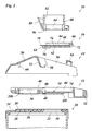
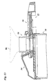
- Figure 1 shows, from the bottom to the top, an upper part of a toner reservoir 10 of, for example, a copier, a drawer 12 slidably disposed on top of the toner reservoir 10, a mounting structure 14, a slide 16 and a spout 18 of a refill container.
- a toner reservoir 10 of, for example, a copier
- drawer 12 slidably disposed on top of the toner reservoir 10
- mounting structure 14 a slide 16 and a spout 18 of a refill container.
- the toner reservoir 10 is tightly closed at the top end by a wall 20 which forms a circular refill opening 22 through toner powder may drop into the interior of the toner reservoir.
- the top surface of the wall 20 has to parallel ribs 24 formed symmetrically on both sides of the refill opening 22.
- a cushion 26 of elastomeric material is secured on the top surface of the wall 20 and fills the space between the two ribs 24.
- the cushion 26 is covered by a plastic film 28 which provides the cushion with a smooth surface finish.
- the surface of the film 28 is slightly elevated in comparison to the ribs 24.
- the cushion 26 and the film 28 are formed with a through-hole 30 which is concentric with the refill opening 22 but has a slightly smaller diameter.
- the drawer 12 has a handle 32 and a plate 34 which is slidingly supported on the flat top surface of the film 28.
- the plate 34 has a through-hole 36 which, in the position shown in figure 1, is offset from the refill opening 22, so that the refill opening is closed by the plate 34.
- the through-hole 36 may be made to coincide with the refill opening 22.
- the plate 34 has raised lateral walls 38 the top edges of which form inwardly projecting guide rails 40 and outwardly projecting stops 42.
- the portion of the plate 34 between the through-hole 36 and the handle 32 forms an upwardly open recess 44 (figure 1) which has a rounded and inclined rear wall 46 and a notch 48 extending along that wall.
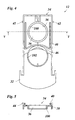
- the mounting structure 14 accommodates the plate 34 of the drawer 12 in the position shown in figure 4 and can firmly be secured to the toner reservoir 10 with fastening means which have not been shown in the drawing for simplicity.
- a top wall 50 of the mounting structure has a curved and inclined portion 52 which, together with a bridge 54 bridging the plate 34, defines and upwardly flaring mounting socket 56 which is open at the bottom side towards the recess 44 of the drawer 12.
- the lower edge of the inclined wall portion 52 is formed with recesses 58 on either side. These recesses are engaged by the guide rails 40 of the drawer 12, so that the drawer is guided by the mounting structure 14 when it is drawn out. The outward movement of the drawer is limited by the stops 42 which cooperate with stops 60 of the mounting structure (figure 1).
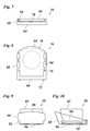
- the slide 16 has a flat bottom 62 with a convexly curved rear edge 64, a front wall 66 and lateral walls 68. Adjacent to the rounded edge 64 the bottom 62 forms a cam 70 which mates with the notch 48 in the bottom of the recess 44 of the drawer 12.
- forwardly projecting abutments 72 of the slide engage the front wall 74 of the recess 44 below the bridge 54 of the mounting structure 14.
- the top surface of the bottom 62 is entirely covered by a thin semi-rigid foil 76 made of a plastic material such as Melinex.
- the foil 66 has a projecting portion 78 which projects beyond the rounded edge 64. When the slide is inserted in recess 44, the projecting portion 78 of the foil overlaps the part of the plate 34 defining the rear edge of the recess 44 and rests flat on the surface of the plate 34.
- the spout 18 shown in figures 1, 9 and 10 comprises a cylindrical tube 80 with a stepped bore 82 which defines a spout hole 84 and may be screwed onto or otherwise tightly secured to the neck of a bottle-shaped refill container 86 shown in phantom lines in figures 11 and 12.
- the tube 80 is surrounded by a downwardly tapered collar 88 which mates with the mounting socket 56 formed in the mounting structure 14.
- the collar 88 has flat side walls 90 formed with grooves 92. These grooves 92 serve for guiding inwardly projecting tongues 94 provided on the side wall 68 of the slide 16. In this way, the slide 16 is slidably mounted to the lower end of the spout 18.
- the bottom surface of the spout 18 is provided with an elastomeric sealing pad 96 which surrounds the spout opening 84 and resiliently engages the top surface of the foil 76, so that the spout opening 84 is tightly closed by the foil 76.
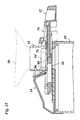
- the component parts of the refill mechanism described above are shown in the assembled state.
- the spout 18 and the slide 16 form part of the refill container 86 as supplied by the manufacturer.
- the edge of the projecting portion 78 of the foil 76 is flush with the curved outer collar 88 of the spout, so that the foil is protected against defection or damage.
- the refill container 86 is placed upside down onto the mounting structure 14, and the abutments 72 of the slide 16 are inserted underneath the bridge 54 and placed against the front wall 74 of the recess 44 in the drawer 12.
- the inclination of the walls 52 and 46 permits to smoothly accommodate the spout 18 and the slide 16 in the mouning socked 56 and the recess 44, resectively, by tilting the refill container 86 into the upright position.
- the cam 70 of the slide is thereby engaged into the notch 48 of the drawer.
- the projecting portion 78 of the foil 76 then rests on the top surface of the plate 34 and covers the gap formed between the rear edge 64 of the slide 16 and the wall 46 of the recess 44.
- the resilient sealing pad 96 slightly expands when it rides over the step 98 formed at the trailing edge of the foil 76 and then wipes over the top surface of the plate 34, so that the toner powder is wiped into the through-hole 36 of the drawer and then drops into the toner reservoir.
- the sweeping action of the sealing pad 96 at the step 98 is improved by the fact that, due to the curvature of the edge of the foil, this edge forms an acute angle with the direction of movement of the pad relative to the foil.
- Figure 13 shows the refill mechanism in the fully open state, in which the through-hole 36 in the plate of the drawer 12 is fully adjusted with the spout opening 84 and the refill opening 22, so that the toner powder may drop into the toner reservoir.
- the drawer 12 is then pushed back into the position shown in figure 11, the slide 16 comes again into engagement with the spout 18, and the projecting part 78 of the foil which then forms the leading edge scrapes over the sealing pad 96 so as to remove any toner powder adhering thereto.
- This toner will then be wiped into the through-hole 36 when the drawer is opened next time.
- the amount of toner powder accumulating behind the step 98 will always be limited, and no substantial toner will enter into the horizontal gap between the lower surface of the sealing pad 96 and the top surface of the slide 16.
- the sealing pad 96 may have a smooth finish at the lower surface, so that no grains of elastomeric material are rubbed-off by the projecting portion 78 of the foil 76.
- the film 28 on the cushion 26 supporting the plate 34 prevents disintegration of the cushion 26.
- the lower surface of the plate 34 of the drawer is formed with two annular embossments 100 and 102, as is shown in figures 1 and 4.
- the embossment 100 surrounds the through-hole 36 in the plate 34, whereas the embossment 102 surrounds the through-hole 30 of the cushion 26 when the drawer is in the closed position.
- a relatively firm engagement of the resiliently supported film 28 with the embossments 100 and 102 assures that any possible toner deposited on the top surface of the foil 28 will be swept into the through-hole 30.
- the plate 34 should be exactly flat or slightly convex, i.e. upwardly bulging, rather than concave, so that the portions of the embossments 100 and 102 which are most firmly pressed against the cushion 26 are the rear portion of the embossment 100 and the front portion of the embossment 102 as viewed in the direction in which the drawer is drawn out.
- top surface of the film 28 is absolutely flat and the drawer 12 is guided only in the mounting structure 14. This has the advantage that toner powder deposited on the film 28 will not enter between the mating surfaces of the guide structures which guide the drawer 12.
- the component parts of the refill mechanism, especially the drawer 12, should be made of a material which has a low adhesiveness for the toner powder.
- POM is a suitable material.
Priority Applications (4)
| Application Number | Priority Date | Filing Date | Title |
|---|---|---|---|
| EP00202625A EP1176477A1 (fr) | 2000-07-24 | 2000-07-24 | Mécanisme de remplissage de poudre de toner |
| JP2001210320A JP4794077B2 (ja) | 2000-07-24 | 2001-07-11 | トナー粉末補充機構 |
| EP01202681.1A EP1179755B1 (fr) | 2000-07-24 | 2001-07-12 | Mécanisme de rechargement de toner |
| US09/910,728 US6463243B1 (en) | 2000-07-24 | 2001-07-24 | Refill mechanism for toner powder |
Applications Claiming Priority (1)
| Application Number | Priority Date | Filing Date | Title |
|---|---|---|---|
| EP00202625A EP1176477A1 (fr) | 2000-07-24 | 2000-07-24 | Mécanisme de remplissage de poudre de toner |
Publications (1)
| Publication Number | Publication Date |
|---|---|
| EP1176477A1 true EP1176477A1 (fr) | 2002-01-30 |
Family
ID=8171845
Family Applications (1)
| Application Number | Title | Priority Date | Filing Date |
|---|---|---|---|
| EP00202625A Withdrawn EP1176477A1 (fr) | 2000-07-24 | 2000-07-24 | Mécanisme de remplissage de poudre de toner |
Country Status (3)
| Country | Link |
|---|---|
| US (1) | US6463243B1 (fr) |
| EP (1) | EP1176477A1 (fr) |
| JP (1) | JP4794077B2 (fr) |
Cited By (1)
| Publication number | Priority date | Publication date | Assignee | Title |
|---|---|---|---|---|
| DE102006007304B3 (de) * | 2006-02-16 | 2007-09-13 | OCé PRINTING SYSTEMS GMBH | Anordnung zur Förderung von Toner aus einem Tonervorratsbehälter in einen Toneraufnahmebehälter insbesondere bei einer Druck- oder Kopiereinrichtung |
Families Citing this family (6)
| Publication number | Priority date | Publication date | Assignee | Title |
|---|---|---|---|---|
| KR100532123B1 (ko) * | 2004-02-21 | 2005-11-29 | 삼성전자주식회사 | 현상장치 및 이를 구비한 전자사진방식 화상형성장치 |
| JP4651011B2 (ja) * | 2005-04-28 | 2011-03-16 | 株式会社リコー | 現像装置、プロセスカートリッジ及び画像形成装置 |
| JP4560443B2 (ja) * | 2005-05-24 | 2010-10-13 | 株式会社リコー | 現像装置および画像形成装置 |
| JP2014531053A (ja) | 2011-10-19 | 2014-11-20 | オセ−テクノロジーズ ビーブイ | トナー補充装置 |
| CN111770884B (zh) * | 2018-02-05 | 2022-08-30 | 埃科莱布美国股份有限公司 | 用于非接触式化学品分配的包装和对接系统 |
| WO2020163470A1 (fr) | 2019-02-05 | 2020-08-13 | Ecolab Usa Inc. | Système d'emballage et d'accueil pour distribution de produit chimique sans contact |
Citations (3)
| Publication number | Priority date | Publication date | Assignee | Title |
|---|---|---|---|---|
| US4834246A (en) * | 1987-03-31 | 1989-05-30 | Fuji Xerox Co., Ltd. | Toner cartridge |
| JPH04128855A (ja) * | 1990-09-20 | 1992-04-30 | Canon Inc | 現像剤補給装置 |
| US5729794A (en) * | 1996-05-20 | 1998-03-17 | Eastman Kodak Company | Toner container having a web seal |
Family Cites Families (8)
| Publication number | Priority date | Publication date | Assignee | Title |
|---|---|---|---|---|
| DE3374352D1 (en) * | 1982-08-23 | 1987-12-10 | Konishiroku Photo Ind | Toner dispensing apparatus |
| US4937628A (en) * | 1989-04-07 | 1990-06-26 | Xerox Corporation | Apparatus for storing and dispensing particulate material |
| JP2565575B2 (ja) * | 1989-12-08 | 1996-12-18 | 三田工業株式会社 | トナーカートリッジ |
| JPH0466983A (ja) * | 1990-07-04 | 1992-03-03 | Mita Ind Co Ltd | トナー補給装置 |
| JPH04301868A (ja) * | 1991-03-29 | 1992-10-26 | Canon Inc | 現像剤収容装置 |
| CA2068358C (fr) * | 1991-05-14 | 1998-12-22 | Yoshihiko Yamada | Cartouche regeneration de revelateur et appareil recevant un revelateur muni d'une telle cartouche |
| JP2802854B2 (ja) * | 1992-04-14 | 1998-09-24 | シャープ株式会社 | トナー補給装置およびトナー容器 |
| JP2810915B2 (ja) * | 1992-07-29 | 1998-10-15 | 三田工業株式会社 | トナーカートリッジ |
-
2000
- 2000-07-24 EP EP00202625A patent/EP1176477A1/fr not_active Withdrawn
-
2001
- 2001-07-11 JP JP2001210320A patent/JP4794077B2/ja not_active Expired - Lifetime
- 2001-07-24 US US09/910,728 patent/US6463243B1/en not_active Expired - Lifetime
Patent Citations (3)
| Publication number | Priority date | Publication date | Assignee | Title |
|---|---|---|---|---|
| US4834246A (en) * | 1987-03-31 | 1989-05-30 | Fuji Xerox Co., Ltd. | Toner cartridge |
| JPH04128855A (ja) * | 1990-09-20 | 1992-04-30 | Canon Inc | 現像剤補給装置 |
| US5729794A (en) * | 1996-05-20 | 1998-03-17 | Eastman Kodak Company | Toner container having a web seal |
Non-Patent Citations (1)
| Title |
|---|
| PATENT ABSTRACTS OF JAPAN vol. 016, no. 393 (P - 1406) 20 August 1992 (1992-08-20) * |
Cited By (2)
| Publication number | Priority date | Publication date | Assignee | Title |
|---|---|---|---|---|
| DE102006007304B3 (de) * | 2006-02-16 | 2007-09-13 | OCé PRINTING SYSTEMS GMBH | Anordnung zur Förderung von Toner aus einem Tonervorratsbehälter in einen Toneraufnahmebehälter insbesondere bei einer Druck- oder Kopiereinrichtung |
| US8139986B2 (en) | 2006-02-16 | 2012-03-20 | Oce Printing Systems Gmbh | Arrangement for conveying toner from a toner supply container into a toner receiving container |
Also Published As
| Publication number | Publication date |
|---|---|
| JP2002082519A (ja) | 2002-03-22 |
| JP4794077B2 (ja) | 2011-10-12 |
| US20020025193A1 (en) | 2002-02-28 |
| US6463243B1 (en) | 2002-10-08 |
Similar Documents
| Publication | Publication Date | Title |
|---|---|---|
| US7536139B2 (en) | Powder container for use in an image forming apparatus having an opening which faces horizontally | |
| EP0843233B1 (fr) | Cartouche de fourniture de toner et appareil de formation d'images | |
| US7840160B2 (en) | Toner cartridge with memory element, image drum unit with the toner cartridge, and image forming apparatus with the image drum unit | |
| RU2754832C2 (ru) | Резервуар для подачи проявителя и система подачи проявителя | |
| JP2007310148A (ja) | トナーカートリッジ | |
| JPS5950985B2 (ja) | トナ−容器 | |
| CN115480467A (zh) | 显影剂供应容器和显影剂供应系统 | |
| EP0892321B1 (fr) | Réservoir de toner et appareil d'alimentation de toner | |
| US6363235B1 (en) | Toner bottle/cartridge housing attachment assembly | |
| EP1176477A1 (fr) | Mécanisme de remplissage de poudre de toner | |
| US8811861B2 (en) | Developer container, image forming apparatus, and developer container controlling method | |
| TWI402637B (zh) | 影像形成劑儲存裝置及影像形成裝置 | |
| EP1434108B1 (fr) | Dispositif de formation d'images avec le support d'une cartouche de toner | |
| KR20110068791A (ko) | 토너 카트리지 및 이를 이용한 화상 형성 장치 | |
| EP1179755B1 (fr) | Mécanisme de rechargement de toner | |
| JP4878499B2 (ja) | トナーカートリッジ | |
| JPH0695505A (ja) | トナー補給装置 | |
| US5970292A (en) | Securing feature for toner container shutter | |
| EP0699972A2 (fr) | Imprimante avec porte de chargement pour toner | |
| CN214795579U (zh) | 碳粉筒 | |
| US5555080A (en) | Slide cover for marking particle cartridge | |
| JP3143495B2 (ja) | 現像剤補給装置と現像剤補充容器 | |
| JP4603859B2 (ja) | トナー供給手段及び画像形成装置 | |
| US7085515B2 (en) | Developer cartridge including sealing gasket | |
| JPH0611964A (ja) | 現像剤補給装置及び該現像剤補給装置を備えた画像形成装置 |
Legal Events
| Date | Code | Title | Description |
|---|---|---|---|
| PUAI | Public reference made under article 153(3) epc to a published international application that has entered the european phase |
Free format text: ORIGINAL CODE: 0009012 |
|
| AK | Designated contracting states |
Kind code of ref document: A1 Designated state(s): AT BE CH CY DE DK ES FI FR GB GR IE IT LI LU MC NL PT SE |
|
| AX | Request for extension of the european patent |
Free format text: AL;LT;LV;MK;RO;SI |
|
| STAA | Information on the status of an ep patent application or granted ep patent |
Free format text: STATUS: THE APPLICATION IS DEEMED TO BE WITHDRAWN |
|
| 18D | Application deemed to be withdrawn |
Effective date: 20011127 |